W6NL Mods for the TS-930 - Kkn.net
W6NL Mods for the TS-930 - Kkn.net
W6NL Mods for the TS-930 - Kkn.net
- No tags were found...

You also want an ePaper? Increase the reach of your titles
YUMPU automatically turns print PDFs into web optimized ePapers that Google loves.
<strong>W6NL</strong> <strong>Mods</strong> <strong>for</strong> <strong>the</strong> <strong>TS</strong>-<strong>930</strong><br />
Introduction<br />
The Kenwood <strong>TS</strong>-<strong>930</strong>, while many years out of production and lacking many of <strong>the</strong> technology<br />
developments of <strong>the</strong> past twenty years, continues to be an excellent HF radio with a unique ability<br />
to hear multiple signals in a pileup. This particular per<strong>for</strong>mance advantage has, <strong>for</strong> whatever<br />
reason, eluded <strong>the</strong> designers of more modern radios. As a partner in <strong>the</strong> new HC8 contest station<br />
on Isla San Cristobal, I undertook to obtain and refurbish a number of <strong>930</strong>s, but we were<br />
disappointed by <strong>the</strong> lack of reliability we experienced.<br />
The problems we observed included<br />
1) Several radios experienced outright power supply failure, and one had a difficult-to-trace low<br />
frequency oscillation in <strong>the</strong> 28V circuit that involved <strong>the</strong> output amplifier, and destroyed amplifier<br />
driver bias transistors (this was cured by replacing <strong>the</strong> 2N5885 regulator transistors).<br />
2) One radio experienced intermittent loss of receiver sensitivity, and ano<strong>the</strong>r experienced loss of<br />
microphone input on SSB.<br />
3) AGC overshoot made reception difficult of signals in <strong>the</strong> range of S9+20 dB.<br />
I aligned each radio and ran it <strong>for</strong> a four-day period at high transmitting duty cycle on CW and<br />
SSB, using computer logging software to transmit into a dummy load (which itself required a<br />
cooling fan). At <strong>the</strong> end of <strong>the</strong> burn-in period I checked <strong>for</strong> unchanged sensitivity, power output<br />
and fan operation. Despite this we experienced failures in contests, with <strong>the</strong> requirement to return<br />
<strong>the</strong> radios to <strong>the</strong> US <strong>for</strong> repair.<br />
I was aware of <strong>the</strong> change of <strong>TS</strong>-<strong>930</strong> design at S/N 310XXXX that responded to <strong>the</strong> many early<br />
problems (digital board through holes, amplifier through holes, receiver muting, sidetone, etc.)<br />
that are well documented in listings of modifications, as well as in Kenwood's application notes.<br />
Our radios have serial numbers ranging from 4M to 8M. All have been standardized to <strong>the</strong> same<br />
configuration, so we would be able to separate <strong>the</strong> sources of any problems. All our radios have<br />
<strong>the</strong> stock CW and SSB IF filters (<strong>TS</strong>-<strong>930</strong> SSB filters are wider than <strong>the</strong> pin-compatible ones <strong>for</strong><br />
<strong>TS</strong>-940/850) and <strong>the</strong> PIEXX digital board, both <strong>for</strong> reliability, new functions such as main tuning<br />
knob control of RIT when dial is locked, and to be able to use computer logging and control.<br />
It should be noted that <strong>the</strong> power situation at <strong>the</strong> end of a long rural line is not favorable, nor is <strong>the</strong><br />
fact that our radios experience <strong>the</strong> rough handling as airline baggage (even in <strong>the</strong> excellent foamlined<br />
Pelican cases) and <strong>the</strong>n sit idle <strong>for</strong> extended periods in <strong>the</strong> foggy and humid equatorial<br />
mountain-top air. In order to minimize our exposure to line voltage variations and surges, we<br />
configured all <strong>the</strong> radios <strong>for</strong> 240V operation and used professional-grade surge protection. The<br />
short line cords are a unique color and are firmly attached to <strong>the</strong> radios so o<strong>the</strong>r equipment in <strong>the</strong><br />
shack cannot inadvertently be connected to 240V through <strong>the</strong> standard EIA connector. We have<br />
<strong>the</strong> option to switch to 220V if <strong>the</strong> line voltage sags, although that has not been necessary.<br />
With <strong>the</strong> modifications outlined in this note, our <strong>TS</strong>-<strong>930</strong>s now exhibit excellent reliability, and<br />
have worked well <strong>for</strong> <strong>the</strong> entire preparation and contest time in both modes of <strong>the</strong> recent CQWW<br />
contest. I thought <strong>the</strong>re might be some interest in what I found was required to make <strong>the</strong>m<br />
bulletproof.<br />
- 1 -<br />
© 2001 D. B. Leeson — publication permitted with attribution
Replacing <strong>TS</strong>-<strong>930</strong> Resistors and Shunt Zeners with Series Regulators<br />
The <strong>TS</strong>-<strong>930</strong> power supply <strong>for</strong> serial numbers higher than 310xxxx generates two voltages, 28.5V<br />
<strong>for</strong> <strong>the</strong> power amplifier and antenna tuner, and 21.7V <strong>for</strong> <strong>the</strong> digital board and <strong>the</strong> signal board.<br />
The 28.5V is regulated by <strong>the</strong> two TO3 pass transistors on <strong>the</strong> heat sink, and <strong>the</strong> 21.7V is<br />
generated by separate trans<strong>for</strong>mer secondary taps and diodes that generate 31.9V which is reduced<br />
to 21.7V by <strong>the</strong> TO220 transistor on <strong>the</strong> power supply heat sink.<br />
Diode<br />
Quad<br />
XFMR<br />
40V<br />
Org<br />
+28.5V<br />
31.9V<br />
Yel<br />
+21.7V<br />
The power switch has a pole that opens <strong>the</strong> +28.5V to most of <strong>the</strong> radio, including <strong>the</strong> circuit that<br />
runs <strong>the</strong> 21.7V regulator. This is apparently so <strong>the</strong> radio will just turn off without <strong>the</strong> time delay<br />
and rude noises of <strong>the</strong> filter capacitors discharging.<br />
The power supply uses high-wattage resistors and zener diodes in <strong>the</strong> power supply fan case to<br />
reduce <strong>the</strong> 21.7V secondary supply voltage 7.5V and 15V <strong>for</strong> <strong>the</strong> digital board (which has 5V and<br />
12V regulators) and <strong>for</strong> <strong>the</strong> signal unit, which has an 18V regulator. The 21.7V is distributed by<br />
<strong>the</strong> yellow wires via a black terminal block between <strong>the</strong> antenna tuner and <strong>the</strong> filter unit; this block<br />
also has <strong>the</strong> switched +28.5V orange wires. The original circuit looks like this:<br />
82Ω<br />
8V<br />
Gray<br />
82Ω<br />
21.7V<br />
Yel<br />
22Ω<br />
15V<br />
White<br />
470 uF<br />
7818<br />
On signal<br />
unit<br />
The main schematic diagram of <strong>the</strong> radio is wrong, it shows <strong>the</strong> 33Ω resistor that is <strong>the</strong> third<br />
supply voltage <strong>for</strong> <strong>the</strong> digital board connected to <strong>the</strong> 21.7V instead of <strong>the</strong> 28.5V line.<br />
The dissipation in <strong>the</strong> resistors and diodes is above <strong>the</strong>ir ratings, and this could be a reliability<br />
18V<br />
- 2 -
problem. This new circuit replaces <strong>the</strong> resistors and diodes with 78xx 1 A. TO220 regulators<br />
mounted on <strong>the</strong> power supply heat sink. In addition to having less dissipation, <strong>the</strong> regulators are<br />
short-circuit proof. There are holes in <strong>the</strong> heat sink, and <strong>the</strong> TO220 tabs can be bolted with 4-40<br />
small-pattern nuts and bolts. I use a locking compound on <strong>the</strong> bolts so <strong>the</strong>y won't vibrate loose<br />
later.<br />
0.33 uF<br />
50V<br />
7808<br />
8V<br />
Gray<br />
1 uF<br />
50V<br />
21.7V<br />
Yel<br />
7815<br />
15V<br />
White<br />
1 uF<br />
50V<br />
470 uF<br />
7818<br />
On signal<br />
unit<br />
The regulators need capacitors near <strong>the</strong>m, especially if <strong>the</strong>y are driving <strong>the</strong> PIEXX board, which<br />
has switching regulators with inductors at <strong>the</strong> input. The regulators should be prewired, and <strong>the</strong><br />
wires are connected to <strong>the</strong> voltage points inside <strong>the</strong> power supply fan case.<br />
To make <strong>the</strong> change, proceed as follows (<strong>the</strong> same steps are necessary to replace <strong>the</strong> pass transistor<br />
with an NTE377, if <strong>the</strong> original is burned out).<br />
1. Unplug <strong>the</strong> radio and remove <strong>the</strong> top cover .<br />
2. Remove <strong>the</strong> four black screws holding <strong>the</strong> fan case onto <strong>the</strong> heat sink, and unplug <strong>the</strong> fan wire<br />
from <strong>the</strong> power supply board so it won't break at <strong>the</strong> fan connection. Free <strong>the</strong> tab from <strong>the</strong> case<br />
bottom, and tip <strong>the</strong> case down and put something under it to hold it horizontally to work on.<br />
3. Remove <strong>the</strong> remaining two black screws holding <strong>the</strong> power supply heat sink to <strong>the</strong> radio. You<br />
will find <strong>the</strong> heat sink will not tip out without additional work.<br />
4. Unscrew <strong>the</strong> screw holding <strong>the</strong> diode bridge to <strong>the</strong> heat sink. This screw will be retained by <strong>the</strong><br />
heavy wires from <strong>the</strong> trans<strong>for</strong>mer, so you don't need to pry it out completely, just free <strong>the</strong> diode<br />
quad from <strong>the</strong> heat sink so <strong>the</strong> heat sink can move.<br />
5. Remove <strong>the</strong> two lugs and heavy red wire from <strong>the</strong> TO3 pass transistors by unscrewing <strong>the</strong> two<br />
middle screws while holding <strong>the</strong> nuts with long-nose pliers on <strong>the</strong> inside. Leave <strong>the</strong> screws in<br />
place in <strong>the</strong> transistors to hold <strong>the</strong> insulating washers.<br />
6. Now you can tip <strong>the</strong> heat sink <strong>for</strong>ward far enough to be able to reach <strong>the</strong> screw that holds <strong>the</strong><br />
pass transistor. This transistor has had loose screws in some radios, so tighten it up while you<br />
can. If you unplug <strong>the</strong> pass transistor, be sure to note which way <strong>the</strong> plug goes on (some have<br />
plugs, some have <strong>the</strong> blue, green and violet leads soldered on and covered with heat shrink tube).<br />
18V<br />
- 3 -
7. Locate <strong>the</strong> field of small holes near <strong>the</strong> upper edge of <strong>the</strong> heat sink, near <strong>the</strong> outside edge of <strong>the</strong><br />
radio. As viewed from inside <strong>the</strong> radio, <strong>the</strong> two regulators mount to <strong>the</strong> holes in <strong>the</strong> bottom row<br />
(<strong>the</strong> top row is also OK, and easier to reach if you are not removing <strong>the</strong> heat sink). Be<strong>for</strong>e you do<br />
anything else, route <strong>the</strong> wires from <strong>the</strong> regulators beneath <strong>the</strong> heat sink so <strong>the</strong>y can be connected to<br />
<strong>the</strong> terminal strips in <strong>the</strong> fan case.<br />
7815<br />
7808<br />
1 uF<br />
0.33 uF<br />
1 uF<br />
Wh<br />
Yel Gray<br />
Blk<br />
8. The 4-40 small pattern nut just fits between <strong>the</strong> heat sink fins. Use a thin tool that can hold <strong>the</strong><br />
nut on <strong>the</strong> end, and orient <strong>the</strong> flats of <strong>the</strong> nut to go between <strong>the</strong> fins. It's helpful if <strong>the</strong> parts are<br />
mag<strong>net</strong>ic, so you can recover a dropped nut (be sure to cover <strong>the</strong> holes in <strong>the</strong> chassis with tissue or<br />
a rag). Use a 4-40x3/8" screw to fasten <strong>the</strong> regulators to <strong>the</strong> heat sink. The same nuts and screws<br />
are used in DB9 and DB25 connector shells. I use some heat sink compound on <strong>the</strong> back of <strong>the</strong><br />
regulators. No insulation is required. Check again to be sure <strong>the</strong> screw <strong>for</strong> <strong>the</strong> TO220 pass<br />
transistor is tight and <strong>the</strong> transistor is oriented up so you can get to <strong>the</strong> terminals.<br />
9. Reconnect <strong>the</strong> lugs to <strong>the</strong> backs of <strong>the</strong> TO3 pass transistors, holding <strong>the</strong> nuts with log-nose<br />
pliers and using a drop of retaining glue or Loctite. Reattach <strong>the</strong> diode quad to <strong>the</strong> heat sink.<br />
10. Attach <strong>the</strong> heat sink to <strong>the</strong> radio with <strong>the</strong> middle black screws. Check that <strong>the</strong>re are no wires<br />
being pinched between <strong>the</strong> heat sink and <strong>the</strong> chassis. Now you can hook up <strong>the</strong> regulator wires to<br />
<strong>the</strong> terminal strips in <strong>the</strong> fan case.<br />
11. The resistors to be replaced are inside <strong>the</strong> power supply fan case. You will notice that <strong>the</strong><br />
resistors will have lost <strong>the</strong>ir color coding from overheating, and <strong>the</strong> terminal strips may be<br />
somewhat charred, from overheating. Cut out <strong>the</strong> two 82Ω resistors and <strong>the</strong>ir zener diode, and cut<br />
out <strong>the</strong> 22Ω resistor and its two zener diodes. You can save <strong>the</strong>se in case of trouble, but <strong>the</strong> new<br />
circuit should be more reliable.<br />
- 4 -
Wh<br />
Blk<br />
Org<br />
82Ω<br />
82Ω<br />
100Ω<br />
FAN<br />
Be sure White<br />
wire is not broken<br />
22Ω<br />
33Ω<br />
23V<br />
7.5V<br />
Yel<br />
Gray<br />
Brn<br />
Wh<br />
Wh<br />
Red<br />
Dial<br />
Lights<br />
Yel<br />
21.7V<br />
7.5V 15V<br />
Digital Board<br />
Org<br />
28.5V<br />
The fan case should now look like this:<br />
Wh<br />
Blk<br />
Org<br />
Yel<br />
Blk<br />
100Ω<br />
FAN<br />
Be sure White<br />
wire is not broken<br />
33Ω<br />
23V<br />
7.5V<br />
Yel<br />
Gray<br />
Brn<br />
Wh<br />
Wh<br />
Gray<br />
Red<br />
Dial<br />
Lights<br />
Yel<br />
Yel<br />
21.7V<br />
7.5V 15V<br />
Digital Board<br />
Blk<br />
Org<br />
28.5V<br />
Wh<br />
- 5 -
Cut to length and solder <strong>the</strong> Yellow, Black, Gray and White wires to <strong>the</strong> terminal strips, making<br />
sure <strong>the</strong>y are connected to <strong>the</strong> same color wire that is already <strong>the</strong>re. Dress <strong>the</strong> wires in place to<br />
avoid <strong>the</strong> fan with a tiny nonmetallic cable tie or twister.<br />
12. Plug in <strong>the</strong> radio, being careful of high voltages at <strong>the</strong> power switch and trans<strong>for</strong>mer.<br />
Connect a digital voltmeter to radio chassis ground and check <strong>the</strong> voltages at <strong>the</strong> terminals in <strong>the</strong><br />
fan case. Turn <strong>the</strong> radio power on momentarily to check each of <strong>the</strong> voltages:<br />
Orange +28.5<br />
Yellow +21.7<br />
White +15<br />
Gray +8<br />
13. Unplug <strong>the</strong> radio. If you wish, you can replace <strong>the</strong> 100Ω resistor with a 5W unit, and <strong>the</strong><br />
33Ω resistor with a 3W unit. Using a piece of wire or an oiler, place a drop of oil on <strong>the</strong> fan shaft.<br />
Check to be sure <strong>the</strong> fan wires aren't broken, and reattach <strong>the</strong> fan case with <strong>the</strong> four black screws.<br />
Plug <strong>the</strong> fan back into <strong>the</strong> power supply board. Replace <strong>the</strong> top cover and test <strong>the</strong> radio.<br />
Replacing <strong>the</strong> 21.7V Pass Transistor<br />
Despite <strong>the</strong> attention in <strong>the</strong> literature to <strong>the</strong> 28.5V TO3 regulators that supply <strong>the</strong> power amplifier,<br />
almost all of our power supply failures have been traced to <strong>the</strong> 21.7V regulator circuit. As <strong>the</strong> pass<br />
transistor is failing <strong>the</strong> radio will typically exhibit unusual operation, such as chirpy signal or<br />
intermittent display.<br />
The 21.7V regulator is a pair of cascaded emitter followers driven by a 22.5V zener diode fed from<br />
<strong>the</strong> 28.5V supply switched through <strong>the</strong> power switch. The zener diode D10 and <strong>the</strong> first transistor<br />
Q6 are on <strong>the</strong> power supply board, and <strong>the</strong> second transistor Q3 is <strong>the</strong> TO220 transistor on <strong>the</strong> heat<br />
sink. The schematic incorrectly shows C13 to be 25 uF 100V (it is 100 uF 25V).<br />
Switched 28C<br />
21.7V Yel<br />
1<br />
2<br />
3<br />
100 UF<br />
25V C13<br />
470Ω<br />
R23<br />
4<br />
5<br />
22.5V<br />
D10<br />
Q6<br />
31.9V<br />
22.1V<br />
Grn<br />
Blu<br />
Vio<br />
Q3 TO220 Pass Transistor on<br />
Heat Sink (2SD843(Y) or NTE377)<br />
21.7V<br />
Use an insulated clip probe. If <strong>the</strong> output of <strong>the</strong> 21.7V supply measures OK on <strong>the</strong> yellow wire at<br />
<strong>the</strong> terminal strips in <strong>the</strong> power supply fan case or <strong>the</strong> black terminal strip in <strong>the</strong> narrow space<br />
between <strong>the</strong> output low-pass filter and <strong>the</strong> antenna tuner, <strong>the</strong>n all is OK.<br />
If <strong>the</strong> voltage is not correct, it will typically be ei<strong>the</strong>r 31.9V or near 0V (say, 0.5V). This means<br />
<strong>the</strong> pass transistor Q3 is ei<strong>the</strong>r shorted or open.<br />
- 6 -
1. Unplug <strong>the</strong> radio and remove <strong>the</strong> top cover .<br />
2. Plug in <strong>the</strong> radio and power on, measure <strong>the</strong> voltage on <strong>the</strong> orange wire, ei<strong>the</strong>r at <strong>the</strong> top of <strong>the</strong><br />
power supply board or at <strong>the</strong> 33Ω resistor in <strong>the</strong> power supply fan case. It should read 28.5V. If<br />
it is OK, <strong>the</strong> 28V regulator on <strong>the</strong> board and <strong>the</strong> pass transistors are OK.<br />
3. Measure <strong>the</strong> voltage on <strong>the</strong> yellow wire, ei<strong>the</strong>r at <strong>the</strong> power supply fan case terminal strips (you<br />
can reach <strong>the</strong>m with an insulated probe in <strong>the</strong> slot above <strong>the</strong> heat sink) or at <strong>the</strong> black terminal strip<br />
in <strong>the</strong> space between <strong>the</strong> output low-pass filter and <strong>the</strong> antenna tuner. If it is approximately 21.7V,<br />
Q3 and Q6/D10 are OK and <strong>the</strong> problem, if any, is not in this part of <strong>the</strong> power supply.<br />
4. If it is not 21.7V, it will typically be ei<strong>the</strong>r approximately zero volts (0.5V or so) or 31.9V.<br />
This means Q3 ei<strong>the</strong>r has an open or it has a collector-emitter short . Usually, but not always, if<br />
Q3 is zapped it will take Q6 and D10 with it. If <strong>the</strong> voltage isn't right, you need to determine if <strong>the</strong><br />
problem is Q3 or Q6 or both. With <strong>the</strong> radio unplugged, unplug <strong>the</strong> 5-pin connector on <strong>the</strong> power<br />
supply board and use a digital voltmeter with a diode scale to check <strong>the</strong> Q3 B-C and B-E diodes;<br />
also check <strong>for</strong> a C-E short. Poke a short length of solder into <strong>the</strong> connector, and use clip-type<br />
meter leads. The readings will typically be (assuming <strong>the</strong> open circuit meter reads 1.4V)<br />
Pins on Red lead Black lead<br />
5-pin conn. on Base on Base<br />
Grn-Blu 2-3 0.7 1.4<br />
Grn-Vio 2-5 0.7 1.4<br />
Blu-Vio 3-5 1.4 1.4<br />
5. If <strong>the</strong> readings are OK, it is likely that <strong>the</strong> problem is on <strong>the</strong> power supply board. If any of<br />
<strong>the</strong>se readings is not as expected, Q3 is dead and will have to be replaced (a remote possibility in<br />
<strong>the</strong> case of an open circuited diode is a bad connection at Q3, so check <strong>the</strong> connector by wiggling<br />
it). If Q3 has blown, it may also have taken Q6 and D10 with it. It is worth disconnecting Q3<br />
be<strong>for</strong>e removing anything and checking Q6 and D10 to determine if you also need to take out <strong>the</strong><br />
power supply board. Ei<strong>the</strong>r unplug <strong>the</strong> connector at Q3 or cut <strong>the</strong> three thin wires right at Q3. Be<br />
careful not to short anything when measuring voltages, as you will hate yourself if you zap a<br />
working circuit while measuring voltages. Reattach <strong>the</strong> 5-pin connector to <strong>the</strong> power supply<br />
board, plug in <strong>the</strong> radio and turn it on momentarily to check <strong>the</strong> voltages on <strong>the</strong> three wires:<br />
Vio 31.9<br />
Grn 22.3<br />
Blu<br />
0 (with Q3 disconnected, 21.7 in working regulator with Q3 connected)<br />
6. If <strong>the</strong>se voltages are OK, <strong>the</strong> PS board is OK; unplug <strong>the</strong> radio and review <strong>the</strong> data<br />
21.7V OK Q3 OK This part of PS is working; check<br />
resistors in PS fan case, look <strong>for</strong><br />
pinched white or gray wires, check<br />
7818 18V regulator on Signal Unit<br />
21.7V bad Q3 OK Probably means Q6/D10 bad; remove<br />
power supply board and replace<br />
21.7V bad, 22.3V (Q6) OK Q3 open or short Replace Q3; Q6/D10 OK<br />
21.7V bad, 22.3V (Q6) bad Q3 open or short Replace Q3 and Q6/D10<br />
- 7 -
Replacing Q3<br />
1. To replace Q3, you need to remove <strong>the</strong> power supply heat sink as in steps 1-6 above. Remove<br />
<strong>the</strong> four black screws holding <strong>the</strong> fan case onto <strong>the</strong> heat sink, and unplug <strong>the</strong> fan wire from <strong>the</strong><br />
power supply board so it won't break at <strong>the</strong> fan connection. Free <strong>the</strong> tab from <strong>the</strong> case bottom,<br />
and tip <strong>the</strong> case down and put something under it to hold it horizontally to work on. Remove <strong>the</strong><br />
remaining two black screws holding <strong>the</strong> power supply heat sink to <strong>the</strong> radio. You will find <strong>the</strong><br />
heat sink will not tip out without additional work. Proceed to free <strong>the</strong> diode quad and <strong>the</strong> lugs on<br />
<strong>the</strong> TO3 transistors so you can get at <strong>the</strong> screw that holds Q3.<br />
2. Now you can tip <strong>the</strong> heat sink <strong>for</strong>ward far enough to be able to reach <strong>the</strong> screw that holds <strong>the</strong><br />
pass transistor. If you unplug <strong>the</strong> pass transistor, be sure to note which way <strong>the</strong> plug goes on<br />
(some have plugs, some have <strong>the</strong> blue, green and violet leads soldered on and covered with heat<br />
shrink tubing, my preference). Remove <strong>the</strong> pass transistor and replace it with a new one. If <strong>the</strong><br />
transistor has a gray silicone insulator under it, use it again with <strong>the</strong> plastic washer to insulate <strong>the</strong><br />
screw; if it has a mica insulator, use a new one and smear a bit of heat sink compound on both<br />
sides be<strong>for</strong>e placing it. If <strong>the</strong>re is a connector, plug it onto <strong>the</strong> transistor now; if you need to solder<br />
<strong>the</strong> wires on, cut <strong>the</strong> pins on <strong>the</strong> transistor shorter and use heat shrink tubing on <strong>the</strong> wires. In<br />
some radios, I've found this screw was not tight so be sure it is snug when you are finished so <strong>the</strong><br />
transistor won't overheat and fail.<br />
If you are going to replace <strong>the</strong> resistors with regulators, now is <strong>the</strong> time to do it while <strong>the</strong> heat sink<br />
is accessible. Also, if Q6/D10 are to be replaced, it's easier to do with <strong>the</strong> heat sink out of <strong>the</strong><br />
way.<br />
3. Reconnect <strong>the</strong> lugs to <strong>the</strong> backs of <strong>the</strong> TO3 pass transistors, holding <strong>the</strong> nuts with long-nose<br />
pliers and using a drop of retaining glue or Loctite. Reattach <strong>the</strong> diode quad to <strong>the</strong> heat sink.<br />
4. Attach <strong>the</strong> heat sink to <strong>the</strong> radio with <strong>the</strong> middle black screws. Check that <strong>the</strong>re are no wires<br />
being pinched between <strong>the</strong> heat sink and <strong>the</strong> chassis. Clean, oil and replace <strong>the</strong> fan.<br />
Replacing Q6 and D10<br />
1. You can check Q6 <strong>for</strong> a collector-emitter short by measuring from pins 1-4 of <strong>the</strong> 5-pin<br />
connector (should show an open with both polarities), but you can't measure all <strong>the</strong> junctions. If<br />
you need to replace Q6 or D10, you will need to remove <strong>the</strong> power supply board. Make a sketch<br />
of where all <strong>the</strong> connectors and wires go. If both Q3 and Q6 are blown and you have <strong>the</strong> heat sink<br />
open, do <strong>the</strong> power supply board repair be<strong>for</strong>e reinstalling <strong>the</strong> heat sink. The power supply board<br />
can be removed without removing <strong>the</strong> heat sink, but it is more convenient to do it be<strong>for</strong>e you<br />
reinstall <strong>the</strong> heat sink if you have replaced Q3.<br />
Unplug <strong>the</strong> inline bayo<strong>net</strong> connector in <strong>the</strong> red wire to <strong>the</strong> power amplifier. Unsolder <strong>the</strong> heavy<br />
yellow and white wires from terminal 28A. Unsolder <strong>the</strong> orange wires from 28B. Unsolder <strong>the</strong><br />
black ground wires from <strong>the</strong> ground terminal. These terminals are at <strong>the</strong> top of <strong>the</strong> power supply<br />
board. Wear safety glasses so you don't flick solder in your eye, and use a solder suction pump to<br />
remove excess solder. Typically, <strong>the</strong> lugs will come unsoldered from <strong>the</strong> circuit board, but it is<br />
easy to put <strong>the</strong>m back straight after <strong>the</strong> wires are unsoldered.<br />
2. Unplug all <strong>the</strong> connectors, noting which goes where. Now remove <strong>the</strong> two screws that hold<br />
<strong>the</strong> bracket to <strong>the</strong> chassis, using a mag<strong>net</strong> (a necessary tool <strong>for</strong> any of <strong>the</strong>se jobs) to reclaim <strong>the</strong>m<br />
so <strong>the</strong>y don't roll down a hole into <strong>the</strong> space under <strong>the</strong> signal board (it's a big job to remove and<br />
- 8 -
eplace it). Lift out <strong>the</strong> power supply board.<br />
3. Remove <strong>the</strong> power supply board from <strong>the</strong> bracket by removing <strong>the</strong> four screws at <strong>the</strong> corners.<br />
Now you can locate Q6 and D10. Once you have gone this far, you might as well replace both,<br />
since it takes a separate setup to measure <strong>the</strong> zener, and <strong>the</strong> transistor is easy enough to change out.<br />
Use a solder suction pump and observe <strong>the</strong> polarity of <strong>the</strong> zener and <strong>the</strong> connections of <strong>the</strong> proper<br />
leads. After <strong>the</strong> old transistor is removed, you can check <strong>the</strong> junctions using <strong>the</strong> digital multimeter.<br />
I'd add a 47 ohm current-limiting resistor in series with <strong>the</strong> collector of Q6.<br />
4. Replace <strong>the</strong> power supply board by reattaching it to <strong>the</strong> bracket, <strong>the</strong>n reattaching <strong>the</strong> bracket to<br />
<strong>the</strong> chassis. Be careful not to pinch under <strong>the</strong> bracket any of <strong>the</strong> wires coming from <strong>the</strong> fan case or<br />
<strong>the</strong> back of <strong>the</strong> chassis. Plug in all <strong>the</strong> connectors. Resolder <strong>the</strong> black wires to <strong>the</strong> ground<br />
terminal, <strong>the</strong> orange wires to <strong>the</strong> 28B lug and <strong>the</strong> yellow and white wires to <strong>the</strong> 28A lug. Make<br />
sure <strong>the</strong> lugs are well-soldered to <strong>the</strong> circuit traces. Plug in <strong>the</strong> red wire to <strong>the</strong> power amplifier.<br />
5. Be<strong>for</strong>e you power up, check with an ohm-meter from <strong>the</strong> orange (28.5V) and yellow wires<br />
(21.7V) to be sure <strong>the</strong>re are no shorts. You should see capacitors charging up in ei<strong>the</strong>r case. If<br />
<strong>the</strong>re is a short, check carefully <strong>for</strong> a pinched wire under <strong>the</strong> power supply board. If this<br />
measurement shows no shorts, plug in <strong>the</strong> radio and power on, measuring <strong>the</strong> voltages on <strong>the</strong><br />
orange and yellow wires (you can reach <strong>the</strong> yellow wire terminal in <strong>the</strong> fan case with a wellinsulated<br />
probe). The voltages should be<br />
Orange 28.5<br />
Yellow 21.7<br />
If OK, you are done and can replace <strong>the</strong> heat sink, fan cover and case top. The 21.7 voltage has<br />
no effect on any critical adjustments, so no realignment is required.<br />
Fan Operation Check or Repair<br />
Check <strong>the</strong> operation of <strong>the</strong> 12V Power Supply fan and <strong>the</strong> 12V Power Amplifier fan by running<br />
into antenna or dummy load at 50W as follows:<br />
Mode:<br />
Send/Rec:<br />
Car:<br />
Power:<br />
TUNE<br />
SEND<br />
Midscale on meter<br />
50W<br />
After a few moments both fans should start up. In any event, proceed to refurbish as follows:<br />
• Unplug radio<br />
• Remove 4 black screws holding metal tabs top and bottom of fan box.<br />
• Tip PS fan assembly back, rotating around wires at bottom (pull some slack in <strong>the</strong> black fan<br />
wire from radio so <strong>the</strong> weight of <strong>the</strong> fan motor won't break <strong>the</strong> connection to <strong>the</strong> fan))<br />
• Fan blades should spin freely when turned by hand, with <strong>the</strong> lumpy feeling of a DC motor<br />
• Check <strong>for</strong> mechanical interference with fan blades, <strong>for</strong> example by fan screen; correct if found<br />
• Fan white wire should read about 60Ω to ground, and black wire should connect to ground; if<br />
- 9 -
motor reads open <strong>the</strong> fan is doomed and will need to be replaced<br />
• Remove 4 silver screws on outside of fan box to remove fan motor assembly<br />
• While fan is out, remove screen and reshape it to bow out enough to ensure clearance<br />
• Place a drop of WD-40 or light oil on <strong>the</strong> bronze bearing where <strong>the</strong> shaft goes through, spin<br />
shaft<br />
• Check <strong>for</strong> mechanical interference; on later serial number radios <strong>the</strong>re is a small flat spring<br />
wiping <strong>the</strong> motor shaft under <strong>the</strong> fan hub to quiet <strong>the</strong> motor, don't damage it<br />
• Being careful not to crush any wires, replace <strong>the</strong> four silver screws to fasten fan to box; make<br />
sure no wires rub <strong>the</strong> fan blades; look in holes and rotate <strong>the</strong> screen to get openings <strong>for</strong> <strong>the</strong> four<br />
screws<br />
• Test fan by plugging in radio, run 50W transmit test with antenna or dummy load; fan should<br />
start and run quietly if motor measured good. Voltage on fan should be 10 to 12 VDC when<br />
PS is hot<br />
• Some have suggested wiring <strong>the</strong> fan to run continuously through a diode from <strong>the</strong> +8V<br />
available in <strong>the</strong> fan case, but this has not proven necessary with <strong>the</strong> power supply modification<br />
to remove <strong>the</strong> shunt regulators, as <strong>the</strong> heat sink runs noticeably cooler after <strong>the</strong> mod<br />
Once PS fan is working, clean and oil <strong>the</strong> Power Amp fan, which comes straight out after four<br />
mounting screws and washers are removed.<br />
If a ei<strong>the</strong>r fan is beyond repair, substitute a replacement or an 80x25mm 12V computer muffin fan.<br />
New holes are needed <strong>for</strong> <strong>the</strong> mounting screws, which are 2.81" on centers (<strong>the</strong> existing holes are<br />
2.45" on centers). Wire <strong>the</strong> red fan wire to <strong>the</strong> white supply wire, and <strong>the</strong> black fan wire to <strong>the</strong><br />
black supply wire.<br />
Lubricating <strong>the</strong> Top Cover Door<br />
The sliding door in <strong>the</strong> top cover becomes very difficult to move after some years of service. Any<br />
time you have removed <strong>the</strong> top cover, lubricate <strong>the</strong> sliding door in <strong>the</strong> top with Silicone liquid or<br />
grease lubricant on <strong>the</strong> plastic slides. Press down one edge, hold in place with screwdriver, wet<br />
<strong>the</strong> corner of piece of paper with Silicone spray, run it between <strong>the</strong> door and <strong>the</strong> lid, do same all<br />
around and also between black plastic and door. This is much easier to do while <strong>the</strong> cover is off.<br />
Be careful of <strong>the</strong> line voltage on <strong>the</strong> POWER switch on <strong>the</strong> front panel, and don't short anything<br />
around <strong>the</strong> power supply voltage regulator. Do not use a petroleum-based lubricant such as WD-<br />
40 on plastic parts, as <strong>the</strong>y will swell and deteriorate.<br />
Line Voltage Change to 240V<br />
Because of low line voltage and neutral wire problems, our 120V line voltage ranged from 106 to<br />
113V, causing hum when <strong>the</strong> regulators dropped out of regulation. Attempts to rewire <strong>the</strong><br />
trans<strong>for</strong>mer <strong>for</strong> 100V operation with low line voltage (below 110V with load) resulted in<br />
overheating of <strong>the</strong> power supply, since with such a large change (20%) <strong>the</strong> unregulated voltages<br />
rise above <strong>the</strong> design limits.<br />
If <strong>the</strong> 120V line voltage is low, use <strong>the</strong> 240 or 220 volt switch position.<br />
• Replace <strong>the</strong> 6A fuse with a 4A fuse; retain <strong>the</strong> 6A fuse if it is desired to change back later<br />
• Turn <strong>the</strong> switch on <strong>the</strong> bottom of <strong>the</strong> radio to 240V, or 220V if <strong>the</strong> voltage is low<br />
• Plug in special yellow 240V line cord, attach to rear panel so it won't be used on a 120V radio<br />
• Plug into a 240V outlet or extension cord (surge absorber preferred, make sure ground is OK)<br />
- 10 -
240V<br />
Yellow<br />
Line Cord<br />
Line Cord<br />
Retainer<br />
240<br />
Line Voltage Switch<br />
on Bottom<br />
Cleaning Signal Unit Connectors with Contact Cleaner<br />
On several occasions receivers have suddenly lost sensitivity <strong>for</strong> extended periods, and o<strong>the</strong>r<br />
radios have had sudden complete interruptions of microphone input. While <strong>the</strong>re can be o<strong>the</strong>r<br />
causes <strong>for</strong> <strong>the</strong>se intermittent failures, <strong>the</strong>y were in each case traced to <strong>the</strong> connectors at <strong>the</strong> Signal<br />
Unit. In all cases <strong>the</strong> intermittent behavior was eliminated by cleaning <strong>the</strong> contacts of <strong>the</strong><br />
connectors in <strong>the</strong> particular signal path.<br />
The idea developed that this reliability issue was due to corrosion of <strong>the</strong> connectors on <strong>the</strong> Signal<br />
Unit. It was decided to clean all of <strong>the</strong> connectors to avoid any recurrence of <strong>the</strong> intermittent<br />
problems, a course which has been successful. In some cases it was possible to observe<br />
discoloration of <strong>the</strong> connectors that was possibly indicative of corrosion.<br />
I remove each and every connector, one by one, and spray or dab <strong>the</strong> pins with contact cleaner,<br />
<strong>the</strong>n rub <strong>the</strong> connector in and out a couple of times. I do all <strong>the</strong> connectors, including <strong>the</strong> filter<br />
connectors and especially <strong>the</strong> microphone and coaxial RF connectors. This has solved several<br />
complaints of intermittent or deaf radio or no transmit audio on SSB. The intermittent problems<br />
went away.<br />
After I did this, I learned from several o<strong>the</strong>r <strong>TS</strong>-<strong>930</strong> users that <strong>the</strong>y had experienced <strong>the</strong> same<br />
problems, and had resolved <strong>the</strong>m in essentially <strong>the</strong> same way.<br />
AGC Modification with Germanium Diode<br />
An AGC modification results in a big improvement in <strong>the</strong> ability to copy signals in <strong>the</strong> S9 to S9+20<br />
range. This modification prevents <strong>the</strong> AGC overshoot that blanks <strong>the</strong> first character of a loud CW<br />
signal, with no bad side effects. A germanium is diode placed across D125 under <strong>the</strong> CW 455<br />
kHz filter, with <strong>the</strong> "bar" end toward <strong>the</strong> rear of <strong>the</strong> radio (opposite to <strong>the</strong> bar on D125). The new<br />
diode is soldered across D125, which is located under <strong>the</strong> large 455 kHz 500 Hz IF filter.<br />
• Unplug radio<br />
• Turn radio upside down and remove bottom cover (8 screws, including <strong>the</strong> ones that hold <strong>the</strong><br />
top cover at <strong>the</strong> sides).<br />
• Locate <strong>the</strong> 500 Hz 455 kHz crystal filter (<strong>the</strong> largest one, on your right as you face <strong>the</strong> bottom<br />
- 11 -
of <strong>the</strong> radio from <strong>the</strong> panel end), lift out harness, remove screw at each end and lift it out.<br />
• Underneath you will see R375 and D125; solder <strong>the</strong> Germanium diode across D125 as shown.<br />
1N270 or<br />
NTE110<br />
R375<br />
D125<br />
• Replace IF filter, being careful not to damage connectors; push <strong>the</strong> connectors down tight<br />
be<strong>for</strong>e you replace <strong>the</strong> screws. Put a label "R375+1N270" on <strong>the</strong> filter to show <strong>the</strong> AGC mod.<br />
• Test <strong>the</strong> radio be<strong>for</strong>e you replace <strong>the</strong> bottom cover; watch out <strong>for</strong> line voltage at <strong>the</strong> back and<br />
behind <strong>the</strong> POWER switch on <strong>the</strong> panel.<br />
• Be<strong>for</strong>e you replace <strong>the</strong> bottom cover, you should also clean <strong>the</strong> connectors on <strong>the</strong> Signal Unit.<br />
Alignment with Non-contacting Pickup <strong>for</strong> Oscillator Frequencies<br />
In some cases it is desired to check or adjust <strong>the</strong> transceiver alignment while not having access to<br />
<strong>for</strong>mal test instruments, and without opening <strong>the</strong> radio and exposing <strong>the</strong> circuits to possible<br />
damage through connecting test leads. Use an insulated wire as a pickup antenna by pushing an<br />
insulated loop through <strong>the</strong> appropriate tuning hole in <strong>the</strong> bottom (or side cover in <strong>the</strong> case of <strong>the</strong> 20<br />
MHz master reference oscillator). A second radio can be used to measure <strong>the</strong> frequency to <strong>the</strong><br />
accuracy required.<br />
The first step should be to check <strong>the</strong> accuracy of <strong>the</strong> reference oscillator. I connected a small<br />
outdoor antenna wire to an insulated loop pushed into <strong>the</strong> side cover opening <strong>for</strong> <strong>the</strong> oscillator<br />
adjustment, with <strong>the</strong> o<strong>the</strong>r end of <strong>the</strong> loop connected to <strong>the</strong> antenna connector on <strong>the</strong> radio. With<br />
this setup, monitor <strong>the</strong> 20 MHz signal of WWV and adjust <strong>the</strong> insertion of <strong>the</strong> loop <strong>for</strong> somewhat<br />
equal signals from <strong>the</strong> external standard and <strong>the</strong> signal from <strong>the</strong> internal oscillator. You will be<br />
able to hear <strong>the</strong> beat note and adjust <strong>the</strong> oscillator <strong>for</strong> zero offset from <strong>the</strong> standard frequency. Let<br />
<strong>the</strong> radio warm up <strong>for</strong> 30 minutes or so to be sure everything has stabilized.<br />
As ano<strong>the</strong>r example, consider <strong>the</strong> alignment of <strong>the</strong> Carrier-2 oscillator used to provide variable<br />
bandwidth. The variable bandwidth tuning (VBT) uses two IF filters, one at 8830 kHz and <strong>the</strong><br />
o<strong>the</strong>r at 455 kHz. The conversion oscillator at 8375 kHz determines <strong>the</strong> degree of overlap of <strong>the</strong><br />
filter passbands. If <strong>the</strong> VBT knobs are set to widest position, <strong>the</strong> conversion oscillator should be<br />
at exactly 8375.0 kHz.<br />
The can be done by connecting a counter (<strong>for</strong> example, an antenna impedance bridge counter)<br />
through a DC-isolated probe to C298 of <strong>the</strong> signal board, but if <strong>the</strong>re's no o<strong>the</strong>r work to be done<br />
leave <strong>the</strong> case closed and use an insulated wire loop poked into <strong>the</strong> hole as an antenna to hear <strong>the</strong><br />
oscillator on a second radio.<br />
VR23 TX/RX<br />
TC3 CAR-2<br />
8375 kHz<br />
L132<br />
C298<br />
wire<br />
to 2nd<br />
radio<br />
Insulated<br />
wire loop<br />
through hole<br />
- 12 -
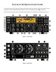
The radio should be set up (see Service Manual, pg. 67, adjustment and test points are on pg. 77)<br />
Mode:<br />
Transmit:<br />
VBT:<br />
USB<br />
REC<br />
CW, High Cut fully CW, Low Cut fully CCW (no narrowing)<br />
• Measure <strong>the</strong> frequency at 8375 kHz<br />
• Adjust VR23 so <strong>the</strong>re is no change in frequency from transmit to receive<br />
• Adjust TC3, <strong>the</strong> small trimmer capacitor, so <strong>the</strong> frequency is exactly 8375.0 kHz<br />
At this time you should also check <strong>the</strong> carrier oscillator at 8830 kHz<br />
CAR1 Conn.<br />
(insert wire)<br />
8830 kHz<br />
VR26 FSK<br />
VR27 TX/RX<br />
TC6 CW<br />
TC5 LSB<br />
TC4 USB<br />
The radio should be set up (see Service Manual, pg. 66, adjustment and test points are on pg. 77)<br />
Mode:<br />
Transmit:<br />
VBT:<br />
USB<br />
REC<br />
CW, High fully CW, Low fully CCW<br />
• Measure <strong>the</strong> oscillator frequency, which should be 8831.5 kHz.<br />
• Adjust VR27 so <strong>the</strong>re is no change in frequency from transmit to receive<br />
• Set TC4 so <strong>the</strong> frequency is 8831.5 (I prefer 8831.6, you can go by <strong>the</strong> sound of <strong>the</strong> receiver<br />
audio to get <strong>the</strong> upper and lower signal levels equal, at +300 and +2.9 kHz.<br />
Now switch to LSB, and set TC5 <strong>for</strong> 8828.5 kHz. Switch back and <strong>for</strong>th between USB and LSB,<br />
and trim <strong>the</strong> LSB oscillator until <strong>the</strong> noise sounds <strong>the</strong> same. Then switch to CW and NARROW,<br />
set TC6 <strong>for</strong> 8830.0 kHz. Last, connect a dummy load or antenna and switch to FSK transmit and<br />
set VR26 <strong>for</strong> 8827.79 kHz.<br />
Last, check <strong>the</strong> setting of <strong>the</strong> CW Pitch and <strong>the</strong> Notch. Turn on <strong>the</strong> Marker oscillator, put <strong>the</strong> rig in<br />
CW mode, and check to see that <strong>the</strong> pitch covers <strong>the</strong> desired range. I set <strong>the</strong> CW Pitch so it is zero<br />
beat with <strong>the</strong> knob at 12 O'clock, so you can tune ei<strong>the</strong>r sideband. The CW Pitch is set by L173 at<br />
<strong>the</strong> far right rear of <strong>the</strong> Signal Unit (bottom of rig). While you have a received tone, check <strong>the</strong><br />
Notch by pushing in <strong>the</strong> NOTCH button and tuning <strong>the</strong> control <strong>for</strong> a null. With <strong>the</strong> offset tone at<br />
1.5 kHz, <strong>the</strong> null should be at 12 O'clock. If it's not close, adjust L167 on <strong>the</strong> Signal Unit.<br />
Don't <strong>for</strong>get to set Moni, Sidetone and o<strong>the</strong>r adjustments (AGC Delay, <strong>for</strong> example) be<strong>for</strong>e <strong>the</strong><br />
radio is stuck under a shelf or cabled in place.<br />
- 13 -
120<br />
SSB<br />
CW<br />
CW<br />
Pitch<br />
Mon Buzz Side<br />
Tone<br />
PWR<br />
FSK<br />
TX/RX<br />
CW<br />
LSB<br />
USB<br />
Notch<br />
L167<br />
VR23 TX/RX<br />
TC3 8.375 MHz<br />
A Note on Alignment Levels<br />
Clif Holland of Avvid, a respected repairer of Kenwood radios, emailed me to note that <strong>the</strong><br />
Japanese specification <strong>for</strong> <strong>the</strong> standard signal generator used in alignment is different from <strong>the</strong> US<br />
signal generator calibration. The <strong>930</strong> service manual refers to signal levels in dBuV, so I had<br />
assumed 0dBuV was 1 uV and 40dBuV was 100uV.<br />
But not so. Clif is right and I'm off by 6 dB. I checked it out, and although I see no mention of<br />
<strong>the</strong> issue in <strong>the</strong> <strong>TS</strong>-<strong>930</strong> or <strong>TS</strong>-950 manuals, I found a table in <strong>the</strong> <strong>TS</strong>-850 service manual, pg. 96,<br />
that confirms this. It has two columns:<br />
Japanese "SG"<br />
-6dB<br />
0dB<br />
6dB<br />
40dB<br />
American "SG"<br />
0.25uV<br />
0.5uV<br />
1uV... etc.<br />
50uV... etc.<br />
Apparently <strong>the</strong> JA generator defines output in terms of open circuit voltage ra<strong>the</strong>r than voltage into<br />
a matched load. This 6 dB difference affects <strong>the</strong> alignment of <strong>the</strong> RF PIN attenuator start point as<br />
well as <strong>the</strong> S-meter settings <strong>for</strong> S1 and S9. Since <strong>the</strong> manual specs are ±4 dB anyway <strong>the</strong><br />
difference will be mighty small except <strong>for</strong> a more active S-meter.<br />
CW Reception on USB<br />
To listen on USB on a <strong>930</strong> in CW mode, adjust <strong>the</strong> "CW Pitch" (BFO) coil L-173 (yellow core,<br />
far<strong>the</strong>st right-rear on bottom, <strong>the</strong>re's a hole) so you have zero-beat at center position (12 o'clock)<br />
on <strong>the</strong> CW PITCH control on <strong>the</strong> front panel. If measuring frequency of this oscillator, this yields<br />
100.0 kHz ra<strong>the</strong>r than 99.2 kHz.<br />
- 14 -
Now if you turn <strong>the</strong> pitch control clockwise from center you get LSB as be<strong>for</strong>e, but if you turn <strong>the</strong><br />
pitch control CCW from center you get USB. No retuning of filters or carrier oscillators is<br />
required. This mod has no effect on SSB.<br />
I use this on our <strong>TS</strong>-<strong>930</strong>s at HC8. The only problems are that it makes <strong>the</strong> TUNE mode zero-beat<br />
if <strong>the</strong> pitch knob is centered, and also if an op isn't familiar with <strong>the</strong> setup on CW it can be<br />
concluded that <strong>the</strong> receiver is not working if <strong>the</strong> pitch knob is centered.<br />
Operating Notes<br />
I found it's difficult to tighten <strong>the</strong> nut on <strong>the</strong> Antenna UHF connector. Lacking a special spanner,<br />
you can carefully tap <strong>the</strong> Antenna connector nut with screwdriver and small hammer, as with <strong>the</strong><br />
nuts in electric boxes. Don't overdo it.<br />
For use with an external receiving antenna, one needs <strong>the</strong> hard-to-find 262 degree 8-pin<br />
"horseshoe" DIN-8 connector used to bring a separate receiving antenna in and out of <strong>the</strong><br />
transverter socket (available from Kenwood and Yaesu, and HRO, but seldom found when<br />
needed). In an emergency we found that a standard DIN-5 connector will plug in and provide<br />
access to <strong>the</strong> receiver input and ground, while <strong>the</strong> small slide switch makes <strong>the</strong> transmit antenna<br />
output available at <strong>the</strong> adjacent RCA phono connector to connect to an receive-antenna selector<br />
switch (inadvertent mis-setting of this switch is a source of occasional complaints of deaf receiver).<br />
Wh<br />
To RX<br />
5<br />
6<br />
3<br />
Gnd<br />
Red<br />
From TR Ry<br />
8<br />
From back of<br />
connector P/N E07-0851-05<br />
Special Kenwood part<br />
DIN-8 262° (not 270°)<br />
RCA Connector<br />
Cable Detail<br />
Twist braid,<br />
solder to flexible wire,<br />
cover with heat shrink<br />
It's good practice to have a relay that disconnects <strong>the</strong> receiver input from any antenna and shorts it<br />
to ground during transmit, so <strong>the</strong> transmit power isn't returned to <strong>the</strong> receiver from a separate<br />
receiving antenna. When used as a second receiver in a multi-op setup, this relay can also be run<br />
by <strong>the</strong> AMP relay line of <strong>the</strong> transmitter on <strong>the</strong> same band.<br />
We don't use <strong>the</strong> noisy and slow amplifier relay (28V to NC pin), but make a transistor switch<br />
adapter in <strong>the</strong> DIN-7 plug <strong>for</strong> <strong>the</strong> PTT input and AMP output. This is faster, less noisy and more<br />
reliable. With <strong>the</strong> AL-1200s we use <strong>the</strong> speedup circuit found on K6XX's web site.<br />
- 15 -
100<br />
3<br />
PTT In<br />
10K<br />
7<br />
Red<br />
1K<br />
Blk<br />
Wh<br />
4<br />
2<br />
Red<br />
+<br />
47 µF<br />
50 V<br />
Inside <strong>TS</strong>-<strong>930</strong><br />
PTT Adapter<br />
Amp Relay Speedup<br />
Red<br />
Wh<br />
Resistor<br />
c<br />
7<br />
e b<br />
Twist braid,<br />
solder to flex wire,<br />
cover with red heat shrink<br />
3<br />
Diode<br />
2<br />
4<br />
RCA Connector<br />
Cable Detail<br />
Naturally, we've had to cure hum and RF problems when using two radios and a microphone<br />
switch box along with a voice recorder, but this has been resolved by using double shielded<br />
twisted pair but not connecting <strong>the</strong> shields at both ends except through RF bypass capacitors. I<br />
have a circuit, based on K8CC's in <strong>the</strong> NA manual, that works very well <strong>for</strong> me. There are some<br />
curious audio/brain effects I've read about in a Bell Labs book on hearing and sound that are<br />
interesting to experiment with, including wiring headphones <strong>for</strong> out-of-phase reception.<br />
One remaining problem is RF leakage of <strong>the</strong> display wave<strong>for</strong>ms on <strong>the</strong> band-select cable from <strong>the</strong><br />
PIEXX board. It appears this should be shielded. With <strong>the</strong> removal of <strong>the</strong> resistors in <strong>the</strong> PS fan<br />
case <strong>the</strong>re is now room <strong>for</strong> some real back-panel connectors, DB9(F) <strong>for</strong> <strong>the</strong> RS-232 connection<br />
and DB25(F) <strong>for</strong> <strong>the</strong> band data. I cut off <strong>the</strong> unneeded wires in <strong>the</strong> RJ45 connector to avoid any<br />
problem with <strong>the</strong> PIEXX board.<br />
References<br />
There are a number of sources of two text files listing mods and fixes <strong>for</strong> <strong>the</strong> early <strong>TS</strong>-<strong>930</strong>.<br />
http://www.qrz.com/download/mods-t-z/ts<strong>930</strong>.txt is an updated version of a posting by WA2ISE<br />
called "<strong>TS</strong><strong>930</strong> repair notes (long)." There are many o<strong>the</strong>r sources of this document, to be found<br />
with any search engine under "ts-<strong>930</strong> mods" or <strong>the</strong> like. The newest version notes that<br />
replacement dial light bulbs should be 28v @ 40ma, not 12V, and that <strong>the</strong> part number <strong>for</strong> <strong>the</strong>se<br />
bulbs is not correct in <strong>the</strong> service manual, and should be B30 0826 05.<br />
- 16 -
http://www.artofhacking.com/Tucops/Radio/two_way/<strong>TS</strong><strong>930</strong>.TXT is one source of a different<br />
document that is "a list of favorite changes that can be made to <strong>the</strong> Kenwood <strong>930</strong>."<br />
http://www.kkn.<strong>net</strong>/~k5tr/ts<strong>930</strong>fix/ts<strong>930</strong>doc.pdf is <strong>the</strong> source of a definitive service bulletin from<br />
TRIO-KENWOOD GMBH about "Digital Unit through-plated hole defects and <strong>the</strong>ir symptoms."<br />
The PDF was created by K5TR from a MS word doc from NØSS.<br />
http://www.qth.<strong>net</strong>/archive/kenwood/, <strong>the</strong> Kenwood mailing list archive, is a great source of<br />
in<strong>for</strong>mation, but is not indexed by subject.<br />
I haven't been able to find a good reference <strong>for</strong> <strong>the</strong> idea of replacing R400 of <strong>the</strong> Signal Unit with a<br />
7912 TO220 regulator (mounted on <strong>the</strong> heat sink at <strong>the</strong> back of <strong>the</strong> Signal Unit). If I were to do<br />
this, I'd clip one lead of <strong>the</strong> 12V zener diode D210.<br />
Using <strong>the</strong> current-limit feature of <strong>the</strong> 723 regulator chip, some have built a protective crowbar<br />
circuit to keep <strong>the</strong> 28.5V from damaging <strong>the</strong> amplifier transistors by running away if <strong>the</strong> regulators<br />
fail. It is <strong>the</strong> same as <strong>the</strong> 28V supply circuit in <strong>the</strong> 1988 ARRL Handbook, and I haven't felt it<br />
necessary (yet). ZL2DX emailed me a copy of a 1992 circuit by NJ6O from <strong>the</strong> Kenwood/IRCI<br />
newsletter, now be available through W2VJN at http://www.qth.com/inrad/pubs.htm.<br />
Replacement Semiconductors<br />
Although <strong>the</strong>re are many sources of <strong>the</strong> original transistors, it has proven convenient and reliable to<br />
use <strong>the</strong> current replacement semiconductors offered in <strong>the</strong> US by NTE. Here is a list of suitable<br />
replacements:<br />
2SD843(Y) NTE377<br />
2SC2235(O) NTE382<br />
XZ-225 NTE5080A<br />
2N5885 NTE181<br />
MRF485 (2) NTE236 (2)<br />
2SC496(Y) NTE295<br />
2SB861(C) NTE398<br />
2SC1815(Y) NTE85<br />
I've looked in vain <strong>for</strong> a TO220 power transistor that does not require <strong>the</strong> insulated mounting, but<br />
have not found one that has low enough <strong>the</strong>rmal impedance and high enough current and power<br />
ratings. I've seen a suggestion to replace <strong>the</strong> 22V emitter follower with a 7824, but this might<br />
sacrifice <strong>the</strong> control by <strong>the</strong> switched 28.5V. I select from <strong>the</strong> NTE5058A (nominally 22V)<br />
individual zeners that provide 22.5 volts; <strong>the</strong> lead length of mounting to <strong>the</strong> circuit board affects <strong>the</strong><br />
voltage, which rises with <strong>the</strong> operating temperature of <strong>the</strong> diode. If I measure <strong>the</strong>m in free air with<br />
clip leads, I get a higher voltage reading because <strong>the</strong>y get a lot hotter after a moment's operation.<br />
I was surprised to be able to make a successful replacement of <strong>the</strong> expensive but burned out<br />
MRF485 RF driver transistors (don't ask!) with <strong>the</strong> relatively inexpensive NTE236. I made no<br />
ef<strong>for</strong>t to match <strong>the</strong> NTE replacements, and <strong>the</strong> amplifier seems to work fine; I reset <strong>the</strong> bias<br />
adjustment per <strong>the</strong> instructions in <strong>the</strong> service manual.<br />
I was concerned about <strong>the</strong> <strong>the</strong>rmal impedance of <strong>the</strong> replacement TO3 transistors NTE181, which<br />
also have relatively low current gain, but a matched pair (NTE offers <strong>the</strong>se designated as<br />
NTE181MP) was used with success to replace a pair of defunct 2N5885 28.5V regulators.<br />
- 17 -
Kenwood Service Bulletin Reference<br />
<strong>TS</strong>-<strong>930</strong>S ASB-0863 INCORRECT LINE VOLTAGE SETTING<br />
<strong>TS</strong>-<strong>930</strong>S ASB-0866 CW HETERODYNE TONE WITH VBT CONTROL<br />
<strong>TS</strong>-<strong>930</strong>S ASB-0867 SSB TX AUDIO TONE QUALITY SN < 3080001<br />
<strong>TS</strong>-<strong>930</strong>S ASB-0868 LOSS OF RX SENSITIVITY<br />
<strong>TS</strong>-<strong>930</strong>S ASB-0869 PLL UNLOCK / BLANK DISPLAY<br />
<strong>TS</strong>-<strong>930</strong>S ASB-0872 CW PITCH TONE SHIFT WHEN MONI SWITCH IS ON<br />
<strong>TS</strong>-<strong>930</strong>S ASB-0873 CW VBT - SIMPLIFIED ALIGNMENT<br />
<strong>TS</strong>-<strong>930</strong>S ASB-0874 RF FEEDBACK WHEN USING EXTERNAL SPEAKER<br />
<strong>TS</strong>-<strong>930</strong>S ASB-0875 RX AUDIO OSCILLATION<br />
<strong>TS</strong>-<strong>930</strong>S ASB-0876 RF FEEDBACK INTO MIC CIRCUIT<br />
<strong>TS</strong>-<strong>930</strong>S ASB-0879 ALC LEVEL DRIFT AT 28 MHZ<br />
<strong>TS</strong>-<strong>930</strong>S ASB-0881 POWER SUPPLY SURGE PROTECTION<br />
<strong>TS</strong>-<strong>930</strong>S ASB-0884 15 MTR INTERNAL BEAT NOTE<br />
<strong>TS</strong>-<strong>930</strong>S ASB-0886 INTERMITTENT TX POWER OUTPUT<br />
<strong>TS</strong>-<strong>930</strong>S ASB-0893 NOISY POWER SUPPLY FAN<br />
ftp://216.98.255.24/Amateur/AmateurServiceBulletins/<br />
- 18 -