FUJI FRENIC 5000P11 & 5000G11 Series Inverters - CTi Automation
FUJI FRENIC 5000P11 & 5000G11 Series Inverters - CTi Automation
FUJI FRENIC 5000P11 & 5000G11 Series Inverters - CTi Automation

Create successful ePaper yourself
Turn your PDF publications into a flip-book with our unique Google optimized e-Paper software.
<strong>CTi</strong> <strong>Automation</strong> - Phone: 800.894.0412 - Fax: 208.368.0415 - Web: www.ctiautomation.net - Email: info@ctiautomation.net<br />
MEH 533 1
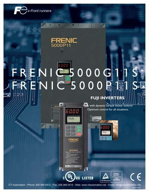
I deal<br />
combination of power and multiple-function.<br />
Dynamic torque-vector control promises<br />
optimum motor control under any operating conditions.<br />
1. Dynamic torque-vector control<br />
Dynamic torque-vector control system<br />
performs high-speed calculation to determine<br />
the required motor power for the load<br />
status. Our key technology is optimal<br />
control of voltage and current vectors for<br />
maximum output torque.<br />
● A high starting torque of 200% at 0.5Hz.*<br />
* 180% for 40HP or larger models.<br />
● Achieves smooth acceleration/<br />
deceleration in the shortest time for the<br />
load condition.<br />
● Using a high-speed CPU quickly<br />
responds to an abrupt load change,<br />
detects the regenerated power to control<br />
the deceleration time. This automatic<br />
decerelation function greatly reduces the<br />
inverter tripping.<br />
● Feedback control with PG<br />
Enables the inverter to execute “vector<br />
control with PG” by adding an optional PG<br />
feedback card to obtain higher performance.<br />
• Speed control range : 1:1200<br />
• Speed control accuracy : 0.02%<br />
• Speed control response : 40Hz<br />
2. Reduced motor wow<br />
at low speed<br />
● Motor wow at low speed (1Hz) reduced to<br />
less than 1/2 of that achieved by<br />
conventional inverters, with the dynamic<br />
torque-vector control system, in<br />
combination with the Fuji’s unique digital<br />
AVR.<br />
2<br />
<strong>CTi</strong> <strong>Automation</strong> - Phone: 800.894.0412 - Fax: 208.368.0415 - Web: www.ctiautomation.net - Email: info@ctiautomation.net<br />
Output torque [%]<br />
0<br />
0<br />
300<br />
200<br />
100<br />
0<br />
100<br />
200<br />
300<br />
Torque characteristics with Dynamic torque-vector control<br />
(Sample: 5HP)<br />
PG Vector Control<br />
Actual torque [%]<br />
Torque reference [%]<br />
Motor speed [r/min]<br />
Motor current [A]<br />
Wow characterisics(Sample: 5HP)<br />
Conventional Fuji inverter<br />
FRN-G11S<br />
100<br />
0<br />
100<br />
0<br />
500<br />
400<br />
20<br />
0<br />
1000 2000<br />
Motor speed<br />
[r/min]<br />
Step load response (Sample : 5HP)<br />
Time<br />
Time<br />
500ms<br />
320ms<br />
14 r/min<br />
5 r/min
3. New on-line tuning system<br />
30°C(86°F)<br />
● On-line tuning to continuously check for<br />
variation of motor characteristics during<br />
running for high-precision speed control.<br />
● This tuning function also available for a<br />
second motor, which allows high-precision<br />
driving of the second motor by changeover<br />
operation between two motors.<br />
4. Environment-friendly<br />
features<br />
● Provided with low-noise control power<br />
supply systems which minimize noise<br />
interference on peripheral devices such as<br />
sensors.<br />
● Equipped with terminals for connecting DC<br />
REACTOR that can suppress harmonics.<br />
● Complied with EMC Directive<br />
(Emission) when<br />
connected to optional EMCcompliance<br />
filter.<br />
3<br />
<strong>CTi</strong> <strong>Automation</strong> - Phone: 800.894.0412 - Fax: 208.368.0415 - Web: www.ctiautomation.net - Email: info@ctiautomation.net<br />
Motor speed [r/min]<br />
0<br />
Motor temperature vs speed variation (Sample: 5HP)<br />
With on-line tuning<br />
Without on-line tuning<br />
Time [min]<br />
80<br />
70°C<br />
(158°F)<br />
Temperature [°C(°F)]
5. Advanced, convenient functions<br />
● 16-step speed with timer control, rotating motor<br />
pick-up control for conveyance machinery<br />
● Automatic energy-saving operation, PID control,<br />
cooling fan on/off control, line/<br />
inverter changeover operation for fans and pumps<br />
● Rotating motor pick-up control:<br />
Restarts motor without any shocks, by detecting motor speed<br />
where motor is coasting after momentary power failure occurs.<br />
● Automatic energy-saving operation function:<br />
Minimizes inverter and motor loss at light load.<br />
Rotating motor pick-up control characteristics (Sample:5HP)<br />
Power source<br />
Motor speed [r/min]<br />
Output current [A]<br />
100<br />
Required power [%]<br />
0<br />
Damper control<br />
Energy<br />
saved<br />
Flow rate [%]<br />
Time<br />
Energy saving effect<br />
Inverter control<br />
(V / f control)<br />
Inverter control<br />
(Automatic energy-saving<br />
control)<br />
6. Global products, communication<br />
100<br />
● Conforms to major world safety standards: UL,<br />
cUL, TÜV (up to 30HP), EN (CE marking)<br />
● Equipped with RS-485 interface as standard.<br />
● Connection to field bus: PROFIBUS-DP, Interbus-<br />
S, DeviceNet, Modbus Plus (Option)<br />
● Universal DI/DO : Monitors digital I/O signal<br />
status and transmits to a host controller, helping<br />
to simplify factory automation.<br />
1. Use the contents of this catalog only for selecting product types and models. When using a product, read the Instruction<br />
Manual beforehand to use the product correctly.<br />
2. Products introduced in this catalog have not been designed or manufactured for such applications in a system or equipment<br />
Safety<br />
that will affect human bodies or lives. Customers, who want to use the products introduced in this catalog for special systems<br />
Precautions or devices such as for atomic-energy control, aerospace use, medical use, and traffic control, are requested to consult the<br />
Fuji's Sales Division. Customers are requested to prepare safety measures when they apply the products introduced in this<br />
catalog to such systems or facilities that will affect human lives or cause severe damage to property if the products become<br />
faulty.<br />
4<br />
<strong>CTi</strong> <strong>Automation</strong> - Phone: 800.894.0412 - Fax: 208.368.0415 - Web: www.ctiautomation.net - Email: info@ctiautomation.net
7. Intelligent Keypad panel<br />
● Copy function: Easily copies<br />
function codes and data to other<br />
inverters.<br />
● Six languages (English, French,<br />
German, Italian, Spanish, and<br />
Japanese) are available as standard.<br />
● Jogging (inching) operation from the Keypad<br />
or external signal<br />
● Remote operation using optional extension<br />
cable (CBIII-10R-¤¤¤)<br />
8. Protective functions,<br />
Maintenance<br />
Protection<br />
● Motors with various characteristics<br />
can be used by setting thermal<br />
time constant for the electronic<br />
thermal overload protection.<br />
● Input phase loss protective function protects<br />
the inverter from damage caused by disconnection<br />
of power supply lines.<br />
● Motor is protected with a PTC thermistor.<br />
● Input terminals for auxiliary control power<br />
supply (2HP or larger models) : Alarm signal<br />
output will be held even if main circuit power<br />
supply has shut down.<br />
Excellent maintainability<br />
The items below can be monitored on the<br />
Keypad panel and making it easy to analyze the<br />
cause of trip and to take preventive measures.<br />
● Input/output terminals check<br />
● Life expectancy of main-circuit capacitors<br />
● Inverter on-load factor<br />
● Accumlated operation time<br />
● Inverter operating condition (output current,<br />
heat sink temperature, input power, etc.)<br />
● Detailed data on trip cause<br />
G11S/P11S<br />
9. Extensive product line<br />
● Two series are available: G11S<br />
series ranging from 1/4 to 600HP<br />
for general industrial machines<br />
and P11S series ranging from<br />
7.5 to 800HP for fans and<br />
pumps.<br />
● Totally-enclosed casing (NEMA1) (up to 30HP<br />
as standard).<br />
● Optional NEMA1 enclosure available for 40HP<br />
or larger models.<br />
10. Other useful functions<br />
● Side-by-side mounting (up to 30HP) saves<br />
space when inverters are installed in a panel.<br />
● The uniform height (10.24inch(260mm)) of<br />
products (up to 10HP) makes it easy to design<br />
panels.<br />
● User-definable control terminals: Digital input (9<br />
points), transistor output (4points), and relay<br />
contact output (1point).<br />
● Active drive feature: Performs prolonged<br />
acceleration at reduced torque, monitoring the<br />
load status to prevent tripping.<br />
● Stall prevention function is provided as standard.<br />
Active or inactive can be also selected.<br />
Output torque [%]<br />
Torque characteristics with Dynamic torque-vector control<br />
200<br />
100<br />
90<br />
50<br />
Continuous operation torque<br />
(with dynamic torque-vector control)<br />
up to 10HP<br />
15 to 30HP<br />
100% of output torque refers<br />
to the rated torque of the motor<br />
driven at 60Hz.<br />
Short-time operation torque<br />
(with dynamic torque-vector control)<br />
1 6 15 20 60<br />
Output frequency [Hz]<br />
120<br />
* The above graph shows an example of torque<br />
characteristics when combining <strong>FRENIC</strong><strong>5000G11</strong>S<br />
(up to 30HP at dynamic torque-vector control) with<br />
Fuji standard three-phase motor (8-type series, 4<br />
poles). Continuous operation torque is for limits of<br />
allowable load torque for using the motor within the<br />
allowable temperature range and is not for motor<br />
output torque.<br />
The motor output torque is shown by the short-time<br />
operation torque.<br />
<strong>CTi</strong> <strong>Automation</strong> - Phone: 800.894.0412 - Fax: 208.368.0415 - Web: www.ctiautomation.net - Email: info@ctiautomation.net
Variation<br />
Easy to apply to customer systems. A consistent design concept in all models from 1/4HP to 800HP.<br />
Nominal<br />
applied<br />
motors [HP]<br />
1/4<br />
1/2<br />
1<br />
2<br />
3<br />
5<br />
7.5<br />
10<br />
15<br />
20<br />
25<br />
30<br />
40<br />
50<br />
60<br />
75<br />
100<br />
125<br />
150<br />
200<br />
250<br />
300<br />
350<br />
400<br />
450<br />
500<br />
600<br />
700<br />
800<br />
<strong>FRENIC</strong><strong>5000G11</strong>S series<br />
for general industrial machines<br />
230V<br />
FRNF25G11S-2UX<br />
FRNF50G11S-2UX<br />
FRN001G11S-2UX<br />
FRN002G11S-2UX<br />
FRN003G11S-2UX<br />
FRN005G11S-2UX<br />
FRN007G11S-2UX<br />
FRN010G11S-2UX<br />
FRN015G11S-2UX<br />
FRN020G11S-2UX<br />
FRN025G11S-2UX<br />
FRN030G11S-2UX<br />
FRN040G11S-2UX<br />
FRN050G11S-2UX<br />
FRN060G11S-2UX<br />
FRN075G11S-2UX<br />
FRN100G11S-2UX<br />
FRN125G11S-2UX<br />
460V<br />
FRNF50G11S-4UX<br />
FRN001G11S-4UX<br />
FRN002G11S-4UX<br />
FRN003G11S-4UX<br />
FRN005G11S-4UX<br />
FRN007G11S-4UX<br />
FRN010G11S-4UX<br />
FRN015G11S-4UX<br />
FRN020G11S-4UX<br />
FRN025G11S-4UX<br />
FRN030G11S-4UX<br />
FRN040G11S-4UX<br />
FRN050G11S-4UX<br />
FRN060G11S-4UX<br />
FRN075G11S-4UX<br />
FRN100G11S-4UX<br />
FRN125G11S-4UX<br />
FRN150G11S-4UX<br />
FRN200G11S-4UX<br />
FRN250G11S-4UX<br />
FRN300G11S-4UX<br />
FRN350G11S-4UX<br />
FRN400G11S-4UX<br />
FRN450G11S-4UX<br />
FRN500G11S-4UX<br />
FRN600G11S-4UX<br />
230V<br />
FRN007P11S-2UX<br />
FRN010P11S-2UX<br />
FRN015P11S-2UX<br />
FRN020P11S-2UX<br />
FRN025P11S-2UX<br />
FRN030P11S-2UX<br />
FRN040P11S-2UX<br />
FRN050P11S-2UX<br />
FRN060P11S-2UX<br />
FRN075P11S-2UX<br />
FRN100P11S-2UX<br />
FRN125P11S-2UX<br />
FRN150P11S-2UX<br />
How to read the model number<br />
Code <strong>Series</strong> name<br />
FRN <strong>FRENIC</strong> 5000 series<br />
Code Nominal applied motors [HP]<br />
F25 1/4HP<br />
F50 1/2HP<br />
001 1HP<br />
002 2HP<br />
to to<br />
800 800HP<br />
Code Application range<br />
G General industrial machines<br />
P Fans and pumps<br />
<strong>FRENIC</strong><strong>5000P11</strong>S series<br />
for fans and pumps (variable torque loads)<br />
FRN007P11S-4UX<br />
FRN010P11S-4UX<br />
FRN015P11S-4UX<br />
FRN020P11S-4UX<br />
FRN025P11S-4UX<br />
FRN030P11S-4UX<br />
FRN040P11S-4UX<br />
FRN050P11S-4UX<br />
FRN060P11S-4UX<br />
FRN075P11S-4UX<br />
FRN100P11S-4UX<br />
FRN125P11S-4UX<br />
FRN150P11S-4UX<br />
FRN200P11S-4UX<br />
FRN250P11S-4UX<br />
FRN300P11S-4UX<br />
FRN350P11S-4UX<br />
FRN400P11S-4UX<br />
FRN450P11S-4UX<br />
FRN500P11S-4UX<br />
FRN600P11S-4UX<br />
FRN700P11S-4UX<br />
FRN800P11S-4UX<br />
<strong>FRENIC</strong> 5000G1<br />
industrial plant<br />
Fans<br />
● Air-conditioning system (for<br />
factory, building, office,<br />
hospital, clean room, shop,<br />
and cattle barn)<br />
● Dryer<br />
● Boiler fan<br />
● Fans for controlling furnace<br />
temperature<br />
● Roof fans controlled as a<br />
group<br />
● Refrigerator<br />
● Compressor<br />
● Built-in blower in a filmmanufacturing<br />
machine<br />
● Cooling-tower fans<br />
● Ventilating fans<br />
● Air-conditioning equipment<br />
Food processing machines<br />
● Food mixing machine<br />
● Food slicer<br />
● Grain milling machine<br />
(bread, cake, noodles)<br />
● Tea making machine<br />
● Rice cleaning machine<br />
6 <strong>CTi</strong> <strong>Automation</strong> - Phone: 800.894.0412 - Fax: 208.368.0415 - Web: www.ctiautomation.net - Email: info@ctiautomation.net<br />
460V<br />
Code Protective structure<br />
S Standard<br />
Code Version<br />
UX UX<br />
FRN F50 G 11 S - 4 UX<br />
Code Developed inverter series<br />
11 11 series<br />
Code Input power source<br />
2 Three-phase 230V<br />
4 Three-phase 460V
1S/P11S can be used for almost all<br />
and equipment areas.<br />
Machine tools<br />
● Grinding machine<br />
● Sanding machine<br />
● Milling machine<br />
● Lathe<br />
● Drilling machine<br />
● Turntable<br />
● Work positioning machine<br />
● PC board drilling machine<br />
● Winding machine<br />
● Press<br />
Electric pumps<br />
● Tankless water supply system<br />
● Submersible motor pump<br />
● Vacuum pump<br />
● Fountain pump<br />
● Cooling water pump<br />
● Circulating hot water pump<br />
● Well pump<br />
● Agricultural storage pump<br />
● Water treatment system<br />
● Constant-flow pump<br />
● Sludge pump<br />
Conveyance machinery<br />
● Crane (traveling, traversing, hoisting)<br />
● Automated warehouse<br />
● Conveyor (belt, chain, screw, roller)<br />
● Lift<br />
● Car parking facility<br />
● Elevator, escalator<br />
● Automatic door<br />
● Shutter equipment<br />
● Speed-change gear<br />
Packaging machinery<br />
● Individual packaging/innerpackaging<br />
machine<br />
● Packing machine<br />
● Outer-packaging machine<br />
Paper making/<br />
textile machinery<br />
● Spinning machine<br />
● Knitting machine<br />
● Textile printing<br />
machine<br />
● Industrial sewing<br />
machine<br />
● Synthetic fiber<br />
manufacturing plant<br />
G11S/P11S<br />
Chemical machinery/wood<br />
working machines<br />
● Fluid mixing machine<br />
● Extruder<br />
● Vibrator<br />
● Centrifugal separator<br />
● Coating machine<br />
● Take-up roller<br />
● Routing machine<br />
● Sanding machine<br />
● Planing machine<br />
Other machinery<br />
● Automated feed/medicine mixer<br />
● Commercial-use washing<br />
machine<br />
● Offset printing press<br />
● Book-binding machine<br />
● Car-washing machine<br />
● Shredder<br />
● Dishwasher<br />
● Test equipment<br />
● Crusher<br />
7<br />
<strong>CTi</strong> <strong>Automation</strong> - Phone: 800.894.0412 - Fax: 208.368.0415 - Web: www.ctiautomation.net - Email: info@ctiautomation.net
Standard Specifications<br />
<strong>FRENIC</strong><strong>5000G11</strong>S 230V, for general industrial machines<br />
Type FRN¤¤¤G11S-2UX<br />
F25<br />
Nominal applied motor HP 1/4<br />
Rated capacity *1) kVA 0.6<br />
Rated voltage *2) V 3-phase 200V/50Hz 200, 220V, 230V/60Hz<br />
Output Rated current *3) A 1.5 3.0 5.0 8.0 11 17 25 33 46 59 74 87 115 145 180 215 283 346<br />
ratings Overload capability 150% of rated current for 1min. 150% of rated current for 1min.<br />
200% of rated current for 0.5s 180% of rated current for 0.5s<br />
Rated frequency Hz 50, 60Hz<br />
Phases, Voltage, Frequency 3-phase 200 to 230V 50/60Hz 3-phase 200 to 220V/50Hz (220 to 230V/50Hz) *5)<br />
200 to 230V/60Hz<br />
Voltage / frequency variations Voltage : +10 to –15% ( Voltage unbalance *6) : 2% or less ) Frequency :+5 to –5%<br />
Input<br />
Momentary voltage dip capability *7) When the input voltage is 165V or more, the inverter can be operated continuously.<br />
When the input voltage drops below 165V from rated voltage, the inverter can be operated for 15ms .<br />
ratings<br />
The smooth recovery method is selectable.<br />
Rated current *8) (with DCR) 0.94 1.6 3.1 5.7 8.3 14.0 19.7 26.9 39.0 54.0 66.2 78.8 109 135 163 199 272 327<br />
A (without DCR) 1.8 3.4 6.4 11.1 16.1 25.5 40.8 52.6 76.9 98.5 117 136 168 204 243 291 - -<br />
Required power<br />
supply capacity *9) kVA 0.4 0.6 1.1 2.0 2.9 4.9 6.9 9.4 14 19 23 28 38 47 57 69 95 114<br />
Control Starting torque 200% (with Dynamic torque-vector control selected) 180% (with Dynamic torque-vector control selected)<br />
Braking torque 150% 100% 20% *10) 10 to 15% *10)<br />
Time s 10 5 5 No limit<br />
Braking Duty cycle % 10 5 3 5 3 2 3 2 No limit<br />
Braking torque (Using options) 150% 100%<br />
DC injection braking Starting frequency: 0.1 to 60.0Hz Braking time: 0.0 to 30.0s Braking level: 0 to 100% of rated current<br />
Enclosure (IEC 60529) IP 40 (NEMA1) IP 00 ( NEMA1: Option )<br />
Cooling method Natural cooling Fan cooling<br />
-UL/cUL -Low Voltage Directive -EMC Directive TÜV (up to 30HP)<br />
Standards<br />
-IEC 61800-2 (Ratings, specifications for low voltage adjustable frequency a.c. power drive systems)<br />
-IEC 61800-3 (EMC product standard including specific test methods)<br />
Weight lbs(kg)<br />
4.9<br />
(2.2)<br />
4.9<br />
(2.2)<br />
5.5<br />
(2.5)<br />
8.4<br />
(3.8)<br />
8.4<br />
(3.8)<br />
8.4<br />
(3.8) 13.4<br />
(6.1) 13.4<br />
(6.1)<br />
22<br />
(10)<br />
22<br />
(10)<br />
23.1<br />
(10.5) 23.1<br />
(10.5) 63.9<br />
(29)<br />
79.4<br />
(36)<br />
97<br />
(44) 101.4<br />
(46) 154.3<br />
(70) 253.5<br />
F50 001 002 003 005 007 010 015 020 025 030 040 050 060 075 100 125<br />
1/2 1 2 3 5 7.5 10 15 20 25 30 40 50 60 75 100 125<br />
1.2 2.0 3.2 4.4 6.8 9.9 13 18 23 29 36 46 58 72 86 113 138<br />
(115)<br />
Standard<br />
<strong>FRENIC</strong><strong>5000G11</strong>S 460V, for general industrial machines<br />
Type FRN¤¤¤G11S-4UX F50 001 002 003 005 007 010 015 020 025 030 040 050 060 075 100 125 150 200 250 300 350 400 450 500 600<br />
Nominal applied motor HP 1/2 1 2 3 5 7.5 10 15 20 25 30 40 50 60 75 100 125 150 200 250 300 350 400 450 500 600<br />
Rated capacity *1) kVA 1.2 2.0 2.9 4.4 7.2 10 14 19 24 31 36 48 60 73 89 120 140 167 202 242 300 331 414 466 518 590<br />
Rated voltage *2) V 3-phase 380, 400, 415V/50Hz 380, 400, 440, 460V/60Hz<br />
Output Rated current *3) A 1.5 2.5 3.7 5.5 9 13 18 24 30 39 45 60 75 91 112 150 176 210 253 304 377 415 520 585 650 740<br />
ratings Overload capability 150% of rated current for 1min.<br />
150% of rated current for 1min.<br />
200% of rated current for 0.5s<br />
180% of rated current for 0.5s<br />
Rated frequency Hz<br />
Phases, Voltage, Frequency 3-phase 380 to 480V 50/60Hz 3-phase 380 to 440V/50Hz 380 to 480V/60Hz *4)<br />
Voltage / frequency variations Voltage : +10 to –15% ( Voltage unbalance *6) : 2% or less ) Frequency :+5 to –5%<br />
Momentary voltage dip When the input voltage is 310V or more, the inverter can be operated continuously.<br />
Input<br />
ratings<br />
capability *7)<br />
Rated current *8) (with DCR)<br />
When the input voltage drops below 310V from rated voltage, the inverter can be operated for 15ms.<br />
The smooth recovery method is selectable.<br />
0.82<br />
A (without DCR) 1.8<br />
Required power<br />
supply capacity *9)<br />
kVA<br />
Control Starting torque<br />
200% (with Dynamic torque-vector control selected) 180% (with Dynamic torque-vector control selected)<br />
Braking torque 150% 100% 20% *10)<br />
10 to 15% *10)<br />
Time s<br />
Braking Duty cycle % 5<br />
Braking torque (Using options)<br />
150% 100%<br />
DC injection braking Starting frequency: 0.1 to 60.0Hz Braking time: 0.0 to 30.0s Braking level: 0 to 100% of rated current<br />
Enclosure (IEC 60529)<br />
IP 40 (NEMA1) IP 00 ( NEMA1: Option )<br />
Cooling method<br />
Natural cooling Fan cooling<br />
-UL/cUL -Low Voltage Directive -EMC Directive TÜV (up to 30HP)<br />
Standards<br />
-IEC 61800-2 (Ratings, specifications for low voltage adjustable frequency a.c. power drive systems)<br />
-IEC 61800-3 (EMC product standard including specific test methods)<br />
Weight lbs(kg)<br />
4.9<br />
(2.2) 5.5<br />
(2.5) 8.4<br />
(3.8) 8.4<br />
(3.8) 8.4<br />
(3.8) 14.3<br />
(6.5) 14.3<br />
(6.5) 22<br />
(10) 22<br />
(10) 23.1<br />
(10.5) 23.1<br />
(10.5) 63.9<br />
(29) 75<br />
(34) 86<br />
(39) 88.2<br />
(40) 105.8<br />
(48) 154.3<br />
(70) 154.3<br />
(70) 220.5<br />
(100) 220.5<br />
(100) 308.6<br />
(140) 308.6<br />
(140) 551.2<br />
(250) 551.2<br />
(250) 793.7<br />
(360) 793.7<br />
1.5 2.9 4.2 7.1 10.0 13.5 19.8 26.8 33.2 39.3 54 67 81 100 134 160 196 232 282 352 385 491 552 624 704<br />
3.5 6.2 9.2 14.9 21.5 27.9 39.1 50.3 59.9 69.3 86 104 124 150 - - - - - - - - - - -<br />
0.6 1.1 2.1 3.0 5.0 7.0 9.4 14 19 24 28 38 47 57 70 93 111 136 161 196 244 267 341 383 433 488<br />
5<br />
5 No limit<br />
3 5 3 2 3 2<br />
No limit<br />
(360)<br />
Standard<br />
50, 60Hz<br />
NOTES: *1) Inverter output capacity (kVA) at 460V in 460V, 230V in 230V. *2) Output voltage is proportional to the power supply voltage and cannot exceed the power supply<br />
voltage. *3) Current derating may be required in case of low impedance loads such as high frequency motor. *4) When the input voltage is 380V/50Hz or 380 to 415V/60Hz, the tap<br />
of the auxiliary transformer must be changed. *5) Order individually. *6) Refer to the IEC 61800-3( 5.2.3 ). *7) Tested at standard load condition (85% load). *8) This value is<br />
under <strong>FUJI</strong> original calculation method. (Refer to the Technical Information.) *9) When power-factor correcting DC reactor is used. *10) With a nominal applied motor, this value is<br />
average torque when the motor decelerates and stops from 60Hz. (It may change according to motor loss.)<br />
8<br />
<strong>CTi</strong> <strong>Automation</strong> - Phone: 800.894.0412 - Fax: 208.368.0415 - Web: www.ctiautomation.net - Email: info@ctiautomation.net
Type FRN¤¤¤P11S-2UX<br />
Nominal applied motor HP<br />
Rated capacity *1) kVA<br />
Output<br />
ratings<br />
Input<br />
ratings<br />
<strong>FRENIC</strong><strong>5000P11</strong>S 230V, for fans and pumps<br />
<strong>FRENIC</strong><strong>5000P11</strong>S 460V, for fans and pumps<br />
G11S/P11S<br />
Rated voltage *2) V 3-phase 200V/50Hz 200, 220V, 230V/60Hz<br />
Rated current *3) A 22 29 42 55 67 78 115 145 180 215 283 346 415<br />
Overload capability 110% of rated current for 1min<br />
Rated frequency Hz 50, 60Hz<br />
Phases, Voltage, Frequency 3-phase 200 to 230V 50/60Hz 3-phase 200 to 220V/50Hz (220 to 230V/50Hz) *5) 200 to 230V/60Hz<br />
Voltage / frequency variations Voltage : +10 to –15% ( Voltage unbalance *6) : 2% or less ) Frequency :+5 to –5%<br />
Momentary voltage dip capability *7) When the input voltage is 165V or more, the inverter can be operated continuously.<br />
When the input voltage drops below 165V from rated voltage, the inverter can be operated for 15ms .<br />
The smooth recovery method is selectable.<br />
Rated current *8) (with DCR) 19.7 26.9 39.0 54.0 66.2 78.8 109 135 163 199 272 327 400<br />
A (without DCR) 40.8 52.6 76.9 98.5 117 136 168 204 243 291 - - -<br />
Standard<br />
007<br />
7.5<br />
8.8<br />
010<br />
10<br />
12<br />
015<br />
15<br />
17<br />
020<br />
20<br />
22<br />
Required power<br />
supply capacity *9)<br />
kVA 6.9 9.4 14 19 23 28 38 47 57 69 95 114 139<br />
Control Starting torque 50%<br />
Braking torque *10) 20% 10 to 15%<br />
Time s No limit<br />
Braking Duty cycle % No limit<br />
Braking torque (Using options) 100% 70%<br />
DC injection braking Starting frequency: 0.1 to 60.0Hz Braking time: 0.0 to 30.0s Braking level: 0 to 80% of rated current<br />
Enclosure (IEC 60529) IP 40 (NEMA1) IP 00 ( NEMA1 : Option )<br />
Cooling method Fan cooling<br />
-UL/cUL -Low Voltage Directive -EMC Directive TÜV (up to 30HP)<br />
Standards<br />
-IEC 61800-2 (Ratings, specifications for low voltage adjustable frequency a.c. power drive systems)<br />
-IEC 61800-3 (EMC product standard including specific test methods)<br />
Weight lbs(kg)<br />
12.6<br />
(5.7)<br />
12.6<br />
(5.7)<br />
12.6<br />
(5.7)<br />
22<br />
(10)<br />
22<br />
(10)<br />
23.1<br />
(10.5)<br />
63.9<br />
(29)<br />
63.9<br />
(29)<br />
79.4<br />
(36)<br />
97<br />
(44)<br />
101.4<br />
(46)<br />
154.3<br />
(70)<br />
253.5<br />
(115)<br />
Type FRN¤¤¤P11S-4UX 007 010 015 020 025 030 040 050 060 075 100 125 150 200 250 300 350 400 450 500 600 700 800<br />
Nominal applied motor HP 7.5 10 15 20 25 30 40 50 60 75 100 125 150 200 250 300 350 400 450 500 600 700 800<br />
Rated capacity *1) kVA 10 13 18 24 29 35 48 60 72 89 119 140 167 201 242 300 330 386 414 517 589 668 764<br />
Output<br />
ratings<br />
Rated voltage *2)<br />
Rated current *3)<br />
Overload capability<br />
V<br />
A<br />
3-phase 380, 400, 415V/50Hz 380, 400, 440, 460V/60Hz<br />
12.5 16.5 23 30 37 44 60 75 91 112 150 176<br />
110% of rated current for 1min<br />
210 253 304 377 415 485 520 650 740 840 960<br />
Rated frequency Hz 50, 60Hz<br />
Phases, Voltage, Frequency 3-phase 380 to 480V 50/60Hz 3-phase 380 to 440V/50Hz 380 to 480V/60Hz *4)<br />
Voltage / frequency variations Voltage : +10 to –15% ( Voltage unbalance *6) : 2% or less ) Frequency :+5 to –5%<br />
Momentary voltage When the input voltage is 310V or more, the inverter can be operated continuously.<br />
Input<br />
ratings<br />
dip capability *7)<br />
Rated current *8) (with DCR)<br />
When the input voltage drops below 310V from rated voltage, the inverter can be operated for 15ms.<br />
The smooth recovery method is selectable.<br />
10.0 13.5 19.8 26.8 33.2 39.3 54 67 81 100 134 160 196 232 282 352 385 491 552 624 704 792 880<br />
A (without DCR) 21.5 27.9 39.1 50.3 59.9 69.3 86 104 124 150 - - - - - - - - - - - - -<br />
Required power<br />
supply capacity *9)<br />
kVA 7.0 9.4 14 19 24 28 38 47 57 70 93 111 136 161 196 244 267 341 383 433 488 549 610<br />
Control Starting torque 50%<br />
Braking torque *10)<br />
20% 10 to 15%<br />
Time s<br />
No limit<br />
Braking Duty cycle %<br />
No limit<br />
Braking torque (Using options)<br />
100% 70%<br />
DC injection braking Starting frequency: 0.1 to 60.0Hz Braking time: 0.0 to 30.0s Braking level: 0 to 80% of rated current<br />
Enclosure (IEC 60529)<br />
IP 40 (NEMA1) IP 00 ( NEMA1 : Option )<br />
Cooling method<br />
Fan cooling<br />
Standards<br />
-UL/cUL -Low Voltage Directive -EMC Directive TÜV (up to 30HP)<br />
-IEC 61800-2 (Ratings, specifications for low voltage adjustable frequency a.c. power drive systems)<br />
-IEC 61800-3 (EMC product standard including specific test methods)<br />
Weight lbs(kg)<br />
13.4 13.4 13.4 22<br />
(6.1) (6.1) (6.1) (10)<br />
22<br />
(10)<br />
23.1<br />
(10.5)<br />
63.9 63.9<br />
(29) (29)<br />
75<br />
(34)<br />
86<br />
(39)<br />
88.2 105.8 154.3 154.3 220.5 220.5 308.6 308.6 308.6 551.2 551.2 793.7 793.7<br />
(40) (48) (70) (70) (100) (100) (140) (140) (140) (250) (250) (360) (360)<br />
NOTES: *1) Inverter output capacity (kVA) at 460V in 460V, 230V in 230V. *2) Output voltage is proportional to the power supply voltage and cannot exceed the power supply<br />
voltage. *3) Current derating may be required in case of low impedance loads such as high frequency motor. *4) When the input voltage is 380V/50Hz or 380 to 415V/60Hz, the tap<br />
of the auxiliary transformer must be changed. *5) Order individually. *6) Refer to the IEC 61800-3( 5.2.3 ). *7) Tested at standard load condition (85% load). *8) This value is<br />
under <strong>FUJI</strong> original calculation method. (Refer to the Technical Information.) *9) When power-factor correcting DC reactor (DCR) is used. *10) With a nominal applied motor, this<br />
value is average torque when the motor decelerates and stops from 60Hz. (It may change according to motor loss.)<br />
Standard<br />
<strong>CTi</strong> <strong>Automation</strong> - Phone: 800.894.0412 - Fax: 208.368.0415 - Web: www.ctiautomation.net - Email: info@ctiautomation.net<br />
025<br />
25<br />
27<br />
030<br />
30<br />
31<br />
040<br />
40<br />
46<br />
050<br />
50<br />
58<br />
060<br />
60<br />
72<br />
075<br />
75<br />
86<br />
100<br />
100<br />
113<br />
125<br />
125<br />
138<br />
150<br />
150<br />
165
Common Specifications<br />
Output<br />
frequency<br />
Control<br />
Setting<br />
Item<br />
Maximum frequency<br />
Base frequency<br />
Starting frequency<br />
Carrier frequency *1)<br />
Accuracy (Stability)<br />
Setting resolution<br />
Control method<br />
Voltage / freq. (V/f) characteristic<br />
Torque boost<br />
Operation method<br />
Frequency setting<br />
(Frequency command)<br />
Explanation<br />
G11S<br />
P11S<br />
50 to 400Hz<br />
50 to 120Hz<br />
25 to 400Hz<br />
25 to 120Hz<br />
0.1 to 60Hz, Holding time: 0.0 to 10.0s<br />
0.75 to 15kHz (75HP or smaller)<br />
0.75 to 15kHz (30HP or smaller)<br />
0.75 to 10kHz (100HP or larger)<br />
0.75 to 10kHz (40 to 100HP)<br />
0.75 to 6kHz (125HP or larger)<br />
• Analog setting : ±0.2% of Maximum frequency (at 25±10°C(77±50°F))<br />
• Digital setting : ±0.01% of Maximum frequency (at –10 to +50°C(14 to 122°F))<br />
• Analog setting : • 1/1000 of Maximum frequency ex.) 0.06Hz at 60Hz, 0.12Hz at 120Hz, (0.4Hz at 400Hz: G11S) • 1/3000 for 40HP and above<br />
• Digital setting : 0.01Hz at Maximum frequency of up to 99.99Hz (0.1Hz at Maximum frequency of 100Hz and above)<br />
• LINK setting : • 1/20000 of Maximum frequency ex.) 0.003Hz at 60Hz, 0.006Hz at 120Hz, (0.02Hz at 400Hz: G11S) • 0.01Hz (Fixed)<br />
• V/f control (Sinusoidal PWM control) • Dynamic torque-vector control (Sinusoidal PWM control) • Vector control with PG (*) (G11S only)<br />
Adjustable at base and maximum frequency, with AVR control : 320 to 480V (460V), 80 to 240V (230V)<br />
Selectable by load characteristics: Constant torque load (Auto/manual), Variable torque load (Manual)<br />
• KEYPAD operation : or key, key<br />
• Digital input signal operation : FWD or REV command, Coast-to-stop command, etc.<br />
• LINK operation : RS-485 (Standard)<br />
T-Link (<strong>FUJI</strong> private link), PROFIBUS-DP, Interbus-S, DeviceNet, Modbus Plus, JPCN1 (Option)<br />
• KEYPAD operation: or key<br />
• External potentiometer (*) : 1 to 5kΩ (1/2W)<br />
• Analog input : 0 to +10V DC (0 to +5V DC), 4 to 20mA DC<br />
(Reversible) 0 to ±10V DC (0 to ± 5V DC) ....Reversible operation by polarized signal can be selected.<br />
(Inverse) +10 to 0V DC, 20 to 4mA DC......Inverse mode operation can be selected.<br />
• UP/DOWN control : Output frequency increases when UP signal is ON, and decreases when DOWN signal is ON.<br />
• Multistep frequency : Up to 16 different frequencies can be selected by digital input signal.<br />
• Pulse train input (*) : 0 to 100kp/s<br />
• Digital signal (parallel ) (*) : 16-bit binary<br />
• LINK operation : RS-485 (Standard)<br />
T-Link (<strong>FUJI</strong> private link), RPOFIBUS-DP, Interbus-S, DeviceNet, Modbus Plus, JPCN1 (Option)<br />
Jogging operation<br />
• Programmed PATTERN operation: Max. 7 stages<br />
or key, FWD or REV digital input signal<br />
Running status signal<br />
Transistor output (4 points) : RUN, FAR, FDT, OL, LU, TL, etc.<br />
Relay output (2 points) : • Same as transistor output • Alarm output (for any fault)<br />
Analog output (1 point) : Output frequency, Output current, Output torque, etc.<br />
Pulse output (1 point) : Output frequency, Output current, Output torque, etc.<br />
Acceleration / Deceleration time 0.01 to 3600s : • Independently adjustable acceleration and deceleration • 4 different times are selectable.<br />
Mode select : Linear, S-curve (weak), S-curve (strong), Non-linear<br />
Active drive<br />
When the acceleration time reaches 60s, the motor output torque is automatically reduced to rated torque. Then the motor operation mode is changed to torque limiting operation.<br />
The acceleration time is automatically extended up to 3 times.<br />
Frequency limiter<br />
High and Low limiter can be preset.<br />
Bias frequency<br />
Bias frequency can be preset.<br />
Gain for frequency setting<br />
Gain for frequency setting can be preset. (0.0 to 200.0%) ex.) Analog input 0 to +5V DC with 200% gain results in maximum frequency at 5V DC.<br />
Jump frequency control<br />
Jump frequency (3 points) and its common jump hysteresis width (0 to 30Hz) can be preset.<br />
Rotating motor pick up (Flying start) A rotating motor (including inverse rotating mode) can be smoothly picked up without stopping the motor (speed search method).<br />
Auto-restart after momentary power Automatic restart is available without stopping motor after a momentary power failure (speed search method). When "Smooth recovery" mode is<br />
failure<br />
selected, the motor speed drop is held minimum. (The inverter searches the motor speed, and smoothly returns to setting frequency. Even if the motor<br />
circuit is temporarily opened, the inverter operates without a hitch. )<br />
Line / Inverter changeover operation Controls the switching operation between line power and inverter. The inverter has sequence function inside.<br />
Slip compensation<br />
The inverter output frequency is controlled according to the load torque to keep motor speed constant. When the value is set at<br />
"0.00" and "Torque-vector" is set at "active", the compensation value automatically selects the Fuji standard motor.<br />
Slip compensation can be preset for the second motor.<br />
Droop operation<br />
The motor speed droops in proportion to output torque (–9.9 to 0.0Hz)......G11S only.<br />
Torque limiting<br />
• When the motor torque reaches a preset limiting level, this function automatically adjusts the output frequency to prevent the inverter from tripping due to an overcurrent.<br />
• Torque limiting 1 and 2 can be individually set, and are selectable with a digital input signal.<br />
Torque control<br />
Output torque (or load factor) can be controlled with an analog input signal.....G11S only.<br />
PID control<br />
This function can control flowrate, pressure, etc. (with an analog feedback signal.)<br />
• Reference • KEYPAD operation ( or key) : Setting freq. / Max. freq. X 100 (%) • PATTERN operation : Setting freq./Max. freq. X 100 (%)<br />
signal • Voltage input (Terminal 12 ) : 0 to +10V DC • DI option input (*) : • BCD, setting freq./Max. freq. X 100 (%)<br />
• Current input (Terminal C1 ) : 4 to 20mA DC • Binary, full scale/100 (%)<br />
• Reversible operation with polarity (Terminal 12) : 0 to ±10V DC • Multistep frequency setting : Setting freq./Max. freq. X 100 (%)<br />
• Reversible operation with polarity (Terminal 12 + V1 ) : 0 to ±10V DC • RS-485 : Setting freq./Max. freq. X 100 (%)<br />
• Inverse mode operation (Terminal 12 ) : +10 to 0V DC<br />
• Inverse mode operation (Terminal C1 ) : 20 to 4mA DC<br />
• Feedback signal • Terminal 12 (0 to +10V DC or +10 to 0V DC)<br />
• Terminal C1 (4 to 20mA DC or 20 to 4mA DC)<br />
Automatic deceleration<br />
Torque limiter 1 (Braking) is set at "F41: 0" (Same as Torque limiter 2 (Braking) ).<br />
• In deceleration : The deceleration time is automatically extended up to 3 times the setting time for tripless operation even if braking resistor not used.<br />
• In constant speed operation : Based on regenerative energy, the frequency is increased and tripless operation is active.<br />
Second motor’s setting<br />
This function is used for two motors switching operation.<br />
• The second motor’s V/f characteristics (base and maximum frequency) can be preset.<br />
• The second motor’s circuit parameter can be preset. Torque-vector control can be applied to both motors.<br />
Energy saving operation<br />
This function minimizes inverter and motor losses at light load.<br />
Fan stop operation<br />
This function is used for silent operation or extending the fan's lifetime.<br />
Universal DI<br />
Transmits to main controller of LINK operation.<br />
Universal DO<br />
Outputs command signal from main controller of LINK operation.<br />
Universal AO Outputs analog signal from main controller of LINK operation.<br />
Zero speed control (*)<br />
The stopped motor holds its rotor angle.....G11S only.<br />
Positioning control (*)<br />
The SY option card can be used for positioning control by differential counter method.<br />
Synchronized operation (*)<br />
This function controls the synchronize operation between 2 axes with PGs.<br />
Note: (*) Option *1) Inverter may automatically reduce carrier frequency, in accordance with ambient temperature or output current for protecting inverter.<br />
10<br />
<strong>CTi</strong> <strong>Automation</strong> - Phone: 800.894.0412 - Fax: 208.368.0415 - Web: www.ctiautomation.net - Email: info@ctiautomation.net
Indication Operation mode (Running)<br />
Item Explanation<br />
LED monitor<br />
G11S/P11S<br />
• Output frequency 1 (Before slip compensation) (Hz)<br />
• Output frequency 2 (After slip compensation) (Hz)<br />
Operation monitor & Alarm monitor<br />
• Setting frequency (Hz)<br />
Operation monitor<br />
• Output current (A)<br />
• Displays operation guidance<br />
• Output voltage (V)<br />
• Bargraph: Output frequency (%), Output current (A), Output torque (%)<br />
• Motor synchronous speed (r/min)<br />
Alarm monitor<br />
• Line speed (m/min)<br />
• Load shaft speed (r/min)<br />
• The alarm data is displayed when the inverter trips.<br />
• Torque calculation value (%)<br />
• Input power (kW)<br />
Function setting & monitor<br />
• PID reference value<br />
Function setting<br />
• PID reference value (remote)<br />
• PID feedback value<br />
Displays function codes and its data or data code, and changes the data value.<br />
• Trip history :Cause of trip by code (Even when main power supply is off,<br />
trip history data of the last 4 trips are retained.)<br />
Stopping<br />
Trip mode<br />
Selected setting value or output value<br />
Displays the cause of trip by codes as follows.<br />
Operation condition<br />
• Output frequency (Hz)<br />
• Output current (A)<br />
• Motor synchronous speed (r/min)<br />
• Load shaft speed (r/min)<br />
• OC1 (Overcurrent during acceleration)<br />
• Output voltage (V)<br />
• Line speed (m/min)<br />
• OC2 (Overcurrent during deceleration)<br />
• Torque calculation value (%) • PID reference value<br />
• OC3 (Overcurrent during running at constant speed)<br />
• Setting frequency (Hz)<br />
• Operation condition<br />
• PID feedback value<br />
• Driving torque limiter setting vaiue (%)<br />
• EF (Ground fault)<br />
• Lin (Input phase loss)<br />
(FWD / REV, IL, VL / LU, TL) • Braking togue limiter setting value (%)<br />
• FUS (Fuse blown)<br />
Tester function<br />
• OU1 (Overvoltage during acceleration)<br />
(I/O check)<br />
• OU2 (Overvoltage during deceleration)<br />
• OU3 (Overvoltage running at constant speed)<br />
• Digital I/O : (ON), (OFF)<br />
• Analog I/O: (V), (mA), (H), (p/s)<br />
• LU (Undervoltage)<br />
• OH1 (Overheating at heat sink)<br />
Maintenance data<br />
• OH2 (External thermal relay tripped)<br />
• OH3 (Overtemperature at inside air)<br />
• Operation time (h)<br />
• DC link circuit voltage (V)<br />
• Temperature at inside air (°C)<br />
• Cooling fan operation time (h)<br />
• Communication error times<br />
(KEYPAD,RS-485, Option)<br />
• dBH (Overheating at DB circuit)<br />
• Temperature at heat sink (°C) • ROM version<br />
• OL1 (Motor 1 overload)<br />
• OL2 (Motor 2 overload)<br />
• OLU (Inverter unit overload)<br />
• Maximum current (A)<br />
• Main circuit capacitor life(%)<br />
• Control PC board life (h)<br />
(Inverter, KEYPAD, Option)<br />
• OS (Overspeed)<br />
Load factor calculation<br />
• PG (PG error)<br />
• Er1 (Memory error)<br />
• Measurement time (s)<br />
• Maximum current (A)<br />
• Average current (A)<br />
• Average braking power (%)<br />
• Er2 (KEYPAD panel communication error)<br />
Alarm data<br />
• Er3 (CPU error)<br />
• Output frequency (Hz) • Temperature at inside air (°C)<br />
• Er4 (Option error)<br />
• Er5 (Option error)<br />
• Output current (A)<br />
• Output voltage (V)<br />
• Torque calculation value (%)<br />
• Hest sink temperature (°C)<br />
• Communication error times<br />
(KEYPAD,RS-485, Option)<br />
• Er6 (Operation procedure error)<br />
• Setting frequency (Hz) • Digital input terminal condition<br />
• Er7 (Output phase loss error, impedance imbalance)<br />
• Er7. (Charging circuit alarm, 40HP or larger)<br />
• Operation condition<br />
(FWD / REV, IL, VL / LU, TL)<br />
• Operation time (h)<br />
(Remote, Communication)<br />
• Transistor output terminal condition<br />
• Trip history code<br />
• Er8 (RS-485 error)<br />
• DC link circuit voltage (V) • Multiple alram exist<br />
Charge lamp When the DC link circuit voltage is higher than 50V, the charge lamp is ON.<br />
LCD monitor (Japanese, English, German, French, Spanish, Italian)<br />
Overload Protects the inverter by electronic thermal overload function and by detection of inverter temperature.<br />
Overvoltage Detects DC link circuit overvoltage,and stops the inverter. (460V : 800V DC, 230V : 400V DC)<br />
Undervoltage Detects DC link circuit undervoltage,and stops the inverter. (460V : 400V DC, 230V : 200V DC)<br />
Input phase loss Phase loss protection for power line input.<br />
Overheating Protects the inverter by detection of inverter temperature.<br />
Short-circuit Short-circuit protection for inverter output circuit<br />
Ground fault • Ground fault protection for inverter output circuit (3-phase current detection method) • Zero-phase current detection method (40HP or larger)<br />
Motor overload • The inverter trips,and then protects the motor. • Electronic thermal overload protection can be set for standard motor or inverter motor<br />
• Thermal time constant (0.5 to 75.0 minutes) can be preset for a special motor.<br />
• The second motor's electronic thermal overload protection can be preset for 2-motor changeover operation.<br />
DB resistor overheating • Prevents DB resistor overheating by internal electronic thermal overload relay (10HP or smaller).<br />
• Prevents DB resistor overheating by external thermal overload relay attached to DB resistor (15HP or larger).<br />
(The inverter stops electricity discharge operation to protect the DB resistor.)<br />
Stall prevention • Controls the output frequency to prevent (overcurrent) trip when the output current exceeds the limit value during acceleration.<br />
• Lowers the output frequency to hold almost constant torque when the output current exceeds the limit value during operation at constant speed.<br />
• Controls the output frequency to prevent (overvoltage) trip when the DC link circuit voltage exceeds the limit value during deceleration.<br />
Output phase loss When the inverter executes auto-tuning, detects each phase impedance imbalance.<br />
Motor protection by PTC thermistor When the motor temperature exceeds allowable value, the inverter trips automatically.<br />
Auto reset When the inverter is tripped, it resets automatically and restarts.<br />
Installation location* Free from corrosive gases, flammable gases, oil mist, dusts, and direct sunlight.<br />
Indoor use only.<br />
* If the inverter has to be used in an atmosphere including<br />
the hydrogen sulfide gases, a special model might be available.<br />
Contact Fuji Electric FA.<br />
Altitude 3300ft(1000m) or less. Applicable to 9800ft(3000m) with power derating (-10%/3300ft(1000m))<br />
Ambient temperature –10 to +50 °C(14 to 122°F). For inverters of 30HP or smaller, remove the ventilation covers when operating it at a temperature of 40°C(104°F) or above.<br />
Ambient humidity 5 to 95%RH (non-condensing)<br />
Vibration 3mm at from 2 to less than 9Hz, 9.8m/s2 at from 9 to less than 20Hz,<br />
2m/s2 at from 20 to less than 55Hz (2m/s2 at from 9 to less than 55Hz :G11S 125HP, P11S 150HP or more)<br />
1m/s2 Protection<br />
Condition<br />
(Installation<br />
and<br />
operation)<br />
at from 55 to less than 200Hz,<br />
Storage condition -Temperature : –25 to +65 °C(-13 to 149°F), -Humidity : 5 to 95%RH (non-condensing)<br />
11
12<br />
Terminal Functions<br />
Terminal Functions<br />
Main<br />
circuit<br />
Analong<br />
input<br />
Digital<br />
input<br />
Symbol<br />
L1/R, L2/S,L3/T<br />
U, V, W<br />
P1, P(+)<br />
P(+), N(-)<br />
P(+), DB<br />
G<br />
R0, T0<br />
13<br />
12<br />
Terminal name<br />
Power input<br />
Inverter output<br />
For DC REACTOR<br />
For BRAKING UNIT<br />
For EXTERNAL<br />
BRAKING RESISTOR<br />
Grounding<br />
Auxiliary control<br />
power supply<br />
Potentiometer power supply<br />
Voltage input<br />
Function<br />
Connect a 3-phase power supply.<br />
Connect a 3-phase induction motor.<br />
Connect the DC REACTOR for power-factor correcting or harmonic current reducing.<br />
• Connect the BRAKING UNIT (Option).<br />
• Used for DC bus connection system.<br />
Connect the EXTERNAL BRAKING RESISTOR (Option)<br />
Ground terminal for inverter chassis (housing).<br />
Connect the same AC power supply as that of the main circuit to back up the control circuit<br />
power supply.<br />
+10V DC power supply for frequency setting POT ( POT: 1 to 5kΩ )<br />
• 0 to +10V DC/0 to 100% (0 to +5V DC/0 to 100% )<br />
• Reversible operation can be selected by function setting.<br />
0 to ±10V DC /0 to ±100% (0 to ±5V DC/0 to ±100% )<br />
• Inverse mode operation can be selected by function setting or digital input signal.<br />
+10 to 0V DC/0 to 100%<br />
Remarks<br />
DC REACTOR: 75HP or smaller : Option<br />
100HP or larger : Standard<br />
BRAKING UNIT (Option): G11S: 15HP or larger, P11S: 20HP or larger<br />
G11S : 10HP or smaller, P11S : 15HP or smaller<br />
1HP or smaller: Not correspond<br />
• Allowable maximum output current : 10mA<br />
• Input impedance: 22kΩ<br />
• Allowable maximum input voltage: ±15V DC<br />
• If input voltage is 10 to 15V DC, the inverter estimates<br />
it to10V DC.<br />
(Torque control) Used for torque control reference signal.<br />
(PID control) Used for PID control reference signal or feedback signal.<br />
(PG feedback) Used for reference signal of PG feedback control (option)<br />
V2 Voltage input Frequency is set according to the analog input voltage supplied from an external circuit<br />
• 0 to +10V DC/0 to 100% • Reverse operation: +10 to 0V DC/0 to 100%<br />
* It can be used only one terminal "V2" or "C1" alternatively * Input resistance: 22kΩ<br />
C1 Current input • 4 to 20mA DC/0 to 100%<br />
• Input impedance:250kΩ<br />
• Inverse mode operation can be selected by function setting or digital input signal.<br />
• Allowable maximum input current: 30mA DC<br />
20 to 4mA DC/0 to 100%<br />
• If input current is 20 to 30mA DC , the inverter estimates<br />
it to20mA DC.<br />
(PID control) Used for PID control reference signal or feedback signal.<br />
11 Common Common for analog signal Isolated from terminals CME and CM.<br />
FWD Forward operation<br />
command<br />
FWD - CM: ON ..... The motor runs in the forward direction.<br />
FWD - CM: OFF ..... The motor decelerates and stops.<br />
When FWD and REV are simultaneously ON,the motor<br />
decelerates and stops.<br />
REV Reverse operation REV - CM: ON ..... The motor runs in the reverse direction.<br />
command<br />
REV - CM: OFF ..... The motor decelerates and stops.<br />
X1<br />
X2<br />
X3<br />
X4<br />
X5<br />
Digital input 1<br />
Digital input 2<br />
Digital input 3<br />
Digital input 4<br />
Digital input 5<br />
These terminals can be preset as follows.<br />
• ON state maximum input voltage: 2V<br />
(maximum source current : 5mA)<br />
• OFF state maximum terminal voltage: 22 to 27V<br />
(allowable maximum leakage current: 0.5mA)<br />
X6 Digital input 6<br />
X7 Digital input 7<br />
X8 Digital input 8<br />
X9 Digital input 9<br />
(SS1) Multistep freq. (SS1) : 2 (0, 1) different frequencies are selectable.<br />
Frequency 0 is set by F01 (or C30).<br />
(SS2) selection<br />
(SS1,SS2) : 4 (0 to 3) different frequencies are selectable.<br />
(All signals of SS1 to SS8 are OFF)<br />
(SS4)<br />
(SS1,SS2,SS4) : 8 (0 to 7) different frequencies are selectable.<br />
(SS8)<br />
(SS1,SS2,SS4,SS8) : 16 (0 to 15) different frequencies are selectable.<br />
(RT1) ACC / DEC time selection (RT1) : 2 (0, 1) different ACC / DEC times are selectable.<br />
(RT2)<br />
(RT1,RT2) : 4 (0 to 3) different ACC / DEC times are selectable.<br />
Time 0 is set by F07/F08.<br />
(All signals of RT1 to RT2 are OFF)<br />
(HLD) 3-wire operation Used for 3-wire operation.<br />
Assigned to terminal X7 at factory setting.<br />
stop command (HLD) - CM: ON ..... The inverter self-holds FWD or REV signal.<br />
(HLD) - CM: OFF ..... The inverter releases self-holding.<br />
(BX) Coast-to-stop (BX) - CM: ON ..... Motor will coast-to-stop. (No alarm signal will be output.)<br />
• The motor restarts from 0Hz by turning off BX with the<br />
command<br />
operation command (FWD or REV) ON.<br />
• Assigned to terminal X8 at factory setting.<br />
(RST) Alarm reset<br />
(RST) - CM: ON ..... Faults are reset. (This signal should be held for more than 0.1s.) • During normal operating, this signal is ignored.<br />
• Assigned to X9 at factory setting.<br />
(THR)<br />
Trip command<br />
(External fault)<br />
(THR) - CM: OFF ..... "OH2 trip" occurs and motor will coast-to-stop.<br />
This alarm signal is held internally.<br />
(JOG) Jogging operation (JOG) - CM: ON ..... JOG frequency is effective.<br />
This signal is effective only while the inverter is stopping.<br />
(Hz2/Hz1) Freq. set 2 / Freq. set 1 (Hz2/Hz1) - CM: ON ..... Freq. set 2 is effective.<br />
If this signal is changed while the inverter is running,<br />
the signal is effective only after the inverter stops.<br />
(M2/M1) Motor 2 / Motor 1 (M2/M1) - CM: ON ..... The motor circuit parameter and V/f characteristics are changed<br />
to the second motor's ones.<br />
If this signal is changed while the inverter is running,<br />
the signal is effective only after the inverter stops.<br />
(DCBRK) DC brake command (DCBRK) - CM: ON ..... The DC injection brake is effective. (In the inverter deceleration mode) If the operation command(FWD/REV) is input while DC braking<br />
is effective, the operation command (FWD/REV) has priority.<br />
(TL2/TL1) Torque limiter 2 /<br />
Torque limiter 1<br />
(TL2/TL1) - CM: ON ..... Torque limiter 2 is effective.<br />
(SW50) Switching operation (SW50(SW60)) - CM: ON .....The motor is changed from inverter operation to line operation. Main circuit changeover signals are output through Y1 to<br />
(SW60) between line and inverter (SW50(SW60)) - CM: OFF ..... The motor is changed from line operation to inverter operation. Y5 terinal.<br />
(UP) UP command (UP) - CM: ON ..... The output frequency increases.<br />
When UP and DOWN commands are simultaneously<br />
(DOWN) DOWN command (DOWN) - CM: ON ..... The output frequency decreases.<br />
• The output frequency change rate is determined by ACC / DEC time.<br />
• Restarting frequency can be selected from 0Hz or setting value at the time of stop.<br />
ON,DOWN signal is effective.<br />
(WE-KP) Write enable for KEYPAD (WE-KP) - CM: ON ..... The data is changed by KEYPAD.<br />
(Hz/PID) PID control cancel (Hz/PID) - CM: ON ..... The PID control is canceled,and frequency setting by KEYPAD<br />
( or )is effective.<br />
(IVS) Inverse mode changeover (IVS) - CM: ON ..... Inverse mode is effective in analog signal input.<br />
If this signal is changed while the inverter is running, the signal<br />
is effective only after the inverter stops.<br />
(IL) Interlock signal for 52-2 Connect to auxiliary contact (1NC) of 52-2.<br />
(Hz/TRQ) TRQ control cancel (Hz/TRQ) - CM: ON ..... The torque control is canceled, and ordinary operation is effective.<br />
(LE) Link enable (RS-485, Bus) (LE) - CM: ON ..... The link opereation is effective. Used to switch operation between ordinary<br />
operation and link operation to communication.<br />
RS-485: Standard, Bus: Option<br />
(U-DI) Universal DI This signal is transmitted to main controller of LINK operation.<br />
(STM) Pick up start mode (STM) - CM: ON ..... The "Pick up" start mode is effective.<br />
(PG/Hz) SY-PG enabled (PG/Hz) - CM: ON ..... Synchronized operation or PG-feedback operation is effective. Option<br />
(SYC) Syuhronization command (SYC) - CM: ON ..... The motor is controlled for synchronized operation between 2 axes with PGs. Option<br />
(ZERO) Zero speed command (ZERO) - CM: ON ..... The motor decelerates and holds its rotor angle. This function can be selected at PG feedback control. Option<br />
(STOP1) Forced stop command (STOP1) - CM: ON ..... The motor decelerates and stops.<br />
(STOP2) Forced stop command<br />
with Deceleration time4<br />
(STOP2) - CM: ON ..... The motor decelerates and stops with Deceleration time4.<br />
(EXITE) Pre-exciting command: (EXITE) - CM: ON ..... The magnetic flux can be established preliminary before starting at PG<br />
vector mode.<br />
PLC PLC terminal Connect PLC power supply to avoid malfunction of the inveter that has SINK type digital<br />
input,when PLC power supply is off.<br />
CM Common<br />
Common for digital signal<br />
Isolated from terminals CME and 11.
Analog<br />
output<br />
Pulse<br />
output<br />
Transistor<br />
output<br />
Relay<br />
output<br />
LINK<br />
Terminal Functions<br />
Symbol<br />
FMA<br />
FMP<br />
(11)<br />
Y1<br />
Y2<br />
Y3<br />
Y4<br />
(RUN)<br />
(FAR)<br />
(AL1)<br />
(AL2)<br />
(AL4)<br />
(AL8)<br />
Terminal name<br />
Analog monitor<br />
(Common)<br />
Pulse rate monitor<br />
Transistor output 1<br />
Transistor output 2<br />
Transistor output 3<br />
Transistor output 4<br />
Alarm indication 1<br />
Alarm indication 2<br />
Alarm indication 4<br />
Alarm indication 8<br />
Function<br />
Output voltage (0 to 10V DC) is proportional to selected function’s value as follows.<br />
The proportional coefficient and bias value can be preset.<br />
• Output frequency 1 (Before slip compensation) ( 0 to max. frequency )<br />
• Output frequency 2 (After slip compensation) ( 0 to max. frequency )<br />
• Output current ( 0 to 200% )<br />
• Output voltage ( 0 to 200% )<br />
• Output torque ( 0 to 200% )<br />
• Load factor ( 0 to 200% )<br />
• Input power ( 0 to 200% )<br />
• PID feedback value ( 0 to 100% )<br />
• PG feedback value ( 0 to max. speed )<br />
• DC link circuit voltage ( 460V : 0 to 1000V)<br />
( 230V : 0 to 500V)<br />
• Universal AO ( 0 to 100%)<br />
• Pulse rate mode : Pulse rate is proportional to selected function’s value* (50% duty pulse)<br />
• Average voltage mode : Average voltage is proportional to selected function’s value*<br />
(2670P/S pulse width control)<br />
(CM) (Common) * Kinds of function to be output is same as those of analog output (FMA).<br />
Output the selected signals from the following items.<br />
Inverter running Outputs ON signal when the output frequency is higher than starting frequency.<br />
Frequency equivalence Outputs ON signal when the difference between output frequency and setting frequency is<br />
signal<br />
smaller than FAR hysteresis width.<br />
(FDT1) Frequency level detection Outputs ON signal by comparison of output frequency and preset value (level and hysteresis).<br />
(LU)<br />
Undervoltage<br />
detection signal<br />
Outputs ON signal when the inverter stops by undervoltage while the operation command is ON.<br />
(B/D) Torque polarity Outputs ON signal in braking or stopping mode, and OFF signal in driving mode.<br />
(TL) Torque limiting Outputs ON signal when the inverter is in torque-limiting mode.<br />
(IPF) Auto-restarting Outputs ON signal during auto restart operation mode.(including "restart time")<br />
(OL1) Overload early warning • Outputs ON signal when the electronic thermal value is higher than preset alarm level.<br />
• Outputs ON signal when the output current value is higher than preset alarm level.<br />
(KP) KEYPAD operation mode Outputs ON signal when the inverter is in KEYPAD operation mode.<br />
(STP) Inverter stopping Outputs ON signal when the inverter is stopping mode or in DC braking mode.<br />
(RDY) Ready output Outputs ON signal when the inverter is ready for operation.<br />
(SW88) Line/Inv changeover<br />
(for 88)<br />
Outputs 88's ON signal for Line/Inverter changeover operation.<br />
(SW52-2) Line/Inv changeover<br />
(for 52-2)<br />
Outputs 52-2’s ON signal for Line/Inverter changeover operation.<br />
(SW52-1) Line/Inv changeover<br />
(for 52-1)<br />
Outputs 52-1’s ON signal for Line/Inverter changeover operation.<br />
(SWM2) Motor2/Motor1 Outputs the motor changeover switch ON signal from motor 1 to motor 2.<br />
(AX) Auxiliary terminal Used for auxiliary circuit of 52-1.<br />
Reffer to wiring diagram example.<br />
(for 52-1)<br />
(Same function as AX1, AX2 terminal by <strong>FRENIC</strong>5000G9S series. (40HP or larger))<br />
(TU) Time-up signal Outputs time up signal (100ms ON pulse) at every stage end of PATTERN operation.<br />
(TO) Cycle completion signal Outputs one cycle completion signal (100ms ON pulse) at PATTERN operation.<br />
(STG1) Stage No indication 1 Outputs PATTERN operation’s stage No. by signals STG1, STG2 and STG4.<br />
(STG2) Stage No indication 2<br />
(STG4) Stage No indication 4<br />
Outputs trip alarm No. by signals AL1, AL2, AL4, and AL8.<br />
(FAN) Fan operation signal Outputs the inverter cooling fan operation status signal.<br />
(TRY) Auto-resetting Outputs ON signal at auto resetting mode. (Including "Reset interval")<br />
(U-DO) Universal DO Outputs command signal from main controller of LINK operation.<br />
(OH) Overheat early warning Outputs ON signal when the heat sink temperature is higher than (trip level – 10°C(14°F)), and<br />
outputs OFF signal when the temperature is lower than (trip level – 15°C(5°F)).<br />
(SY) Synchronization<br />
completion signal<br />
Synchronization completion signal for synchronized operation.<br />
(LIFE) Lifetime alarm Outputs ON signal when the calculated lifetime is longer than preset alarm level.<br />
(FDT2) 2nd Freq. level<br />
detection<br />
2nd-outputs ON signal by comparison of output frequency and preset value (FDT2 level).<br />
(OL2) 2nd OL level early 2nd-outputs ON signal when the output current value is larger than preset alarm level<br />
warning<br />
(OL2 level).<br />
(C1OFF) Terminal C1 off signal Outputs ON signal when the C1 current is smaller than 2mA.<br />
(DNZS) Speed existance<br />
signal<br />
Outputs ON signal at detection of motor speed when using OPC-G11S-PG/PG2/SY.<br />
CME Common (transistor<br />
output)<br />
Common for transistor output signal.<br />
30A, 30B, Alarm relay output Outputs a contact signal when a protective function is activated.<br />
30C<br />
Changeable exciting mode active or non-exciting mode active by function "F36".<br />
Y5A, Y5C Relay output Functions can be selected the same as Y1 to Y4.<br />
Changeable exciting mode active or non-exciting mode active by function "E25".<br />
DXA, DXB,<br />
SD<br />
RS-485 I/O terminal Connect the RS-485 link signal.<br />
G11S/P11S<br />
Remarks<br />
Allowable maximum output current: 2mA<br />
Allowable maximum output current : 2mA<br />
• ON state maximum output voltage : 2V<br />
(Allowable maximum sink current : 50mA)<br />
• OFF state maximum leakage current : 0.1mA<br />
(Allowable maximum voltage : 27V)<br />
Option<br />
Isolated from terminals CM and 11.<br />
• Contact rating :<br />
250V AC, 0.3A, cosø=0.3<br />
48V DC, 0.5A, non-inductive<br />
<strong>CTi</strong> <strong>Automation</strong> - Phone: 800.894.0412 - Fax: 208.368.0415 - Web: www.ctiautomation.net - Email: info@ctiautomation.net
Basic Wiring Diagram<br />
Keypad panel Operation<br />
The following diagram is for reference only. For detailed wiring diagrams, refer to the relevant instruction manual.<br />
Power supply ( *1)<br />
3-phase<br />
200 to 230V<br />
50/60Hz<br />
or<br />
3-phase<br />
400 to 480V<br />
50/60Hz<br />
Terminal Arrangement<br />
• Main circuit terminals<br />
FRNF25G11S-2UX~FRN001G11S-2UX / FRNF50G11S-4UX~FRN001G11S-4UX<br />
L1/R L2/S L3/T DB P1 P(+) N(-) U V W<br />
G<br />
G Screw size M3.5<br />
FRN002G11S-2UX~FRN005G11S-2UX / FRN002G11S-4UX~FRN005G11S-4UX<br />
R0 T0<br />
Screw size M3.5<br />
L1/R L2/S L3/T DB P1 P(+) N(-) U V W<br />
G G<br />
Screw size M4<br />
FRN007G11S-2UX~FRN010G11S-2UX / FRN007G11S-4UX~FRN010G11S-4UX<br />
FRN007P11S-2UX~FRN015P11S-2UX / FRN007P11S-4UX~FRN015P11S-4UX<br />
R0 T0<br />
Screw size M3.5<br />
L1/R L2/S L3/T DB P1 P(+) N(-) U V W<br />
G G<br />
Screw size M5<br />
FRN015G11S-2UX~FRN030G11S-2UX / FRN015G11S-4UX~FRN030G11S-4UX<br />
FRN020P11S-2UX~FRN030P11S-2UX / FRN020P11S-4UX~FRN030P11S-4UX<br />
L1/R L2/S L3/T DB P1 P(+) N(-) U V W<br />
G<br />
G<br />
Screw size M6<br />
Screw size M3.5<br />
FRN040G11S-2UX / FRN040G11S-4UX~FRN075G11S-4UX<br />
FRN040P11S-2UX~FRN50P11S-2UX / FRN040P11S-4UX~FRN100P11S-4UX<br />
Screw size M4<br />
R0 T0 U V W<br />
L1/R L2/S L3/T DB P1 P(+) N(-)<br />
G G<br />
MCCB or GFCI ( *2)<br />
Auxiliary control power supply( *5)<br />
Analog input<br />
*Option<br />
Digital input<br />
Screw size M8<br />
R0 T0<br />
L1/R<br />
L2/S<br />
L3/T<br />
P(+)<br />
G<br />
G<br />
Grounding Grounding<br />
Potentiometer power supply<br />
Voltage input<br />
Second voltage input<br />
Current input<br />
Analog output (analog monitor)<br />
Pulse output<br />
(frequency monitor)<br />
Main circuit<br />
G11S:15 to75HP<br />
P11S:7.5 to 75HP<br />
Jumper wire (*3)<br />
P1<br />
(R0)<br />
(T0)<br />
Control circuit<br />
[13]<br />
CNUX ( )<br />
U1 U2<br />
+DC10V<br />
FRN050G11S-2UX~FRN075G11S-2UX / FRN100G11S-4UX~FRN150G11S-4UX<br />
FRN060P11S-2UX~FRN100P11S-2UX / FRN125P11S-4UX~FRN200P11S-4UX<br />
FRN100G11S-2UX<br />
FRN125P11S-2UX<br />
N(-)<br />
R0 T0<br />
U V<br />
L1/R L2/S L3/T DB P1 P(+) N(-)<br />
G G<br />
R0 T0 Screw size M4<br />
FRN125G11S-2UX / FRN200G11S-4UX~FRN350G11S-4UX<br />
FRN150P11S-2UX / FRN250P11S-4UX~FRN450P11S-4UX<br />
U<br />
FRN400G11S-4UX~FRN450G11S-4UX<br />
FRN500P11S-4UX~FRN600P11S-4UX<br />
FRN500G11S-4UX~FRN600G11S-4UX<br />
FRN700P11S-4UX~FRN800P11S-4UX<br />
V<br />
W<br />
0V 30C<br />
[12]<br />
[11]<br />
[V2]<br />
[C1]<br />
30<br />
[FMA]<br />
(PLC)<br />
(FWD)<br />
(REV)<br />
(CM)<br />
(X1)<br />
(X2)<br />
(X3)<br />
(X4)<br />
(X5)<br />
(X6)<br />
(X7)<br />
(X8)<br />
(X9)<br />
(CM)<br />
+DC0~10V<br />
+DC24V 0V<br />
(FMP)<br />
Pulse output<br />
(DXB) (DXA) (SD)<br />
RS-485 interface port<br />
30B<br />
30A<br />
< Y5C ><br />
< Y5A ><br />
< Y4 ><br />
< Y3 ><br />
< Y2 ><br />
< Y1 ><br />
< CME ><br />
W<br />
Screw size G=M8<br />
Other terminals=M10<br />
L1/R L2/S L3/T P1 P(+) N(-) U V W<br />
G G<br />
G G<br />
Screw size G=M10<br />
Other terminals=M12<br />
R0 T0 Screw size M4<br />
L1/R L2/S L3/T U V W<br />
P1 P(+) N(-)<br />
Screw size G=M10<br />
Other terminals=M12<br />
R0 T0 Screw size M4<br />
L1/R L2/S L3/T P1 U V W<br />
L1/R L2/S L3/T P1 U V W<br />
G G<br />
R0 T0<br />
100HP or larger<br />
DC reactor<br />
(DCR)<br />
(*6)<br />
P(+) P(+)<br />
N(-) N(-)<br />
M<br />
Motor*<br />
Screw size G=M10<br />
Other terminals=M12<br />
L1/R L2/S L3/T P1 P(+) N(-) U V W<br />
L1/R L2/S L3/T P1 P(+) N(-) U V W<br />
Screw size R0,T0=M4 G=M10<br />
Other terminals=M12<br />
G G<br />
P1<br />
P(+) N(-)<br />
G<br />
Alarm output (for any fault)<br />
Relay output<br />
Transistor output<br />
G11S:10HP or smaller<br />
(*3)<br />
P1 P(+) DB N(-)<br />
DBR (*4)<br />
NOTE:<br />
Common terminals [11], (CM), and<br />
for control circuits are<br />
isolated from one another.<br />
*1) Use the inverter whose rated input<br />
voltage matches the power supply<br />
voltage.<br />
*2) Use this peripheral device when necessary.<br />
*3) 75HP or smaller:<br />
Terminals [P1] and [P(+)] are connected<br />
with a jumper wire before shipping. When<br />
connecting an optional DC reactor (DCR)*6),<br />
remove the jumper wire that connects the<br />
terminals [P1] and [P(+)].<br />
100HP or larger:<br />
Terminals [P1] and [P(+)] are not connected<br />
at shipment from factory. Be sure to<br />
connect the DC reactor (DCR) *6) standard<br />
provided to these terminals.<br />
*4) For G11S models from 1/4 to 10HP, a<br />
built-in braking resistor (DBR) is connected<br />
to the inverter before shipping. (DBR is not<br />
mounted on G11S models 15HP or larger,<br />
and P11S models.)<br />
*5) Terminals [R0] and [T0] are provided for<br />
G11S models 2HP or larger, and P11S<br />
models. These terminals are not provided for<br />
G11S models 1HP or smaller. Even if<br />
these terminals are not powered, the<br />
inverter can be operated.<br />
Input voltage CNUX connector<br />
400 to 440V/50Hz, 440 to 480V/60Hz U1 (Factory setting)<br />
380V/50Hz (398V or smaller),<br />
380 to 415V/60Hz (430V or smaller)<br />
U2<br />
• Control circuit<br />
terminals<br />
30C<br />
30A<br />
30B<br />
Y5A<br />
Y5C<br />
CMY<br />
Y4<br />
Y3<br />
Y2<br />
Y1<br />
11<br />
C1<br />
12<br />
FMA<br />
13<br />
FMP<br />
V2<br />
PLC<br />
CM<br />
X1<br />
CM<br />
X2<br />
FWD<br />
X3<br />
REV<br />
X4<br />
P24<br />
X5<br />
P24<br />
X6<br />
DX-<br />
X7<br />
DX+<br />
X8<br />
SD<br />
X9
External signal input Operation<br />
G11S/P11S<br />
The following diagram is for reference only. For detailed wiring diagrams, refer to the relevant instruction manual.<br />
Analog input<br />
*Option<br />
MCCB or GFCI ( *3)<br />
Power supply ( *1)<br />
3-phase<br />
200 to 230V<br />
50/60Hz<br />
or<br />
3-phase<br />
400 to 480V<br />
50/60Hz<br />
Auxiliary control power supply ( *7)<br />
Potentiometer power<br />
supply (*2) ( *8)<br />
Digital input<br />
Second<br />
voltage input<br />
Current input<br />
4 to 20mA<br />
Analog frequency meter<br />
(FM) 0 to 60Hz (*2)<br />
( + )<br />
( 0V )<br />
( + )<br />
( - )<br />
Main circuit<br />
L1/R<br />
*1)Use the inverter whose rated input voltage matches the power<br />
supply voltage.<br />
*2)An optional device. Use it when necessary.<br />
*3)Use this peripheral device when necessary.<br />
*4)15HP or smaller:<br />
Terminals [P1] and [P(+)] are connected with a jumper wire<br />
before shipping. When connecting an optional DC reactor<br />
(DCR) *9), remove the jumper wire that connects the terminals<br />
[P1] and [P(+)].<br />
100HP or larger:<br />
Terminals [P1] and [P(+)] are not connected at shipment from<br />
factory. Be sure to connect the DC reactor (DCR) *9) standard<br />
provided to these terminals.<br />
*5) For G11S models from 1/4 to 10HP, a built-in braking resistor<br />
(DBR) is connected to the inverter before shipping. (DBR is not<br />
P1<br />
L2/S<br />
L3/T<br />
(R0)<br />
(T0)<br />
P(+)<br />
G<br />
G<br />
Grounding Grounding<br />
Control circuit<br />
3<br />
2<br />
1<br />
60Hz<br />
Digital frepuency meter<br />
(pulse counter) (*2)<br />
DC reactor (DCR)<br />
(*2) ( *9)<br />
[13]<br />
[12]<br />
[11]<br />
[V2]<br />
[C1]<br />
G11S:15HP or larger<br />
P11S:7.5HP or larger<br />
External braking resistor (DB) (*2) (*6)<br />
2<br />
(CM)<br />
P DB 1<br />
G<br />
P DB 2<br />
G<br />
P N<br />
1<br />
(THR)<br />
Braking unit ( *2) ( *8)<br />
(*4)<br />
CNUX ( )<br />
U1 U2<br />
+DC10V<br />
N(-)<br />
U<br />
V<br />
W<br />
0V 30C<br />
30<br />
[FMA]<br />
(PLC)<br />
(FWD)<br />
(REV)<br />
(CM)<br />
(X1)<br />
(X2)<br />
(X3)<br />
(X4)<br />
(X5)<br />
(X6)<br />
(X7)<br />
(X8)<br />
(X9)<br />
(CM)<br />
+DC0~10V<br />
+DC24V 0V<br />
(FMP)<br />
Pulse output<br />
(DXB) (DXA) (SD)<br />
RS-485 interface port<br />
30B<br />
30A<br />
< Y5C ><br />
< Y5A ><br />
< Y4 ><br />
< Y3 ><br />
< Y2 ><br />
< Y1 ><br />
< CME ><br />
NOTE:<br />
Common terminals [11], (CM),<br />
and for control circuits<br />
are isolated from one another.<br />
Input voltage CNUX connector<br />
400 to 440V/50Hz, 440 to 480V/60Hz U1<br />
380V/50Hz (398V or smaller),<br />
380 to 415V/60Hz (430V or smaller)<br />
U2 (Factory setting)<br />
mounted on G11S models 15HP or larger, and P11S models.)<br />
When connecting an optional external braking resistor (DB),<br />
remove the DBR connection cables from [P(+)] and [DB]<br />
terminals. The end of the removed cables (indicated with an X)<br />
must be insulated.<br />
*6) When connecting an optional external braking resistor (DB), be<br />
sure to also use an optional braking unit *8). Connect the<br />
optional braking unit to the [P(+)] and [N(-)] terminals. Auxiliary<br />
terminals [1] and [2] have polarity.<br />
Be sure to connect cables to these terminals correctly. (See the<br />
diagram)<br />
*7) Terminals [R0] and [T0] are provided for G11S models 2HP or<br />
larger, and P11S models. These terminals are not provided for<br />
G11S models 1HP or smaller. Even if these terminals are not<br />
powered, the inverter can be operated.<br />
15<br />
<strong>CTi</strong> <strong>Automation</strong> - Phone: 800.894.0412 - Fax: 208.368.0415 - Web: www.ctiautomation.net - Email: info@ctiautomation.net<br />
M<br />
Motor*<br />
x x<br />
P(+)<br />
DBR (*5)<br />
G<br />
Alarm output (for any fault)<br />
Relay output<br />
Transistor output<br />
G11S:10HP or smaller<br />
External braking resistor (DB) (*2) (*6)<br />
G<br />
P<br />
DB<br />
2<br />
1<br />
DB N(-)<br />
(CM)<br />
(THR)
Keypad Panel Functions and Operations<br />
Keypad panel<br />
LED monitor<br />
In operation mode:<br />
Displays the setting frequency,<br />
output current, voltage, motor<br />
speed, or line speed.<br />
In trip mode:<br />
Displays code indicating the<br />
cause of trip.<br />
Up/Down keys<br />
In operation mode :<br />
Increases or decreases the<br />
frequency or speed.<br />
In program mode :<br />
Increases or decreases function<br />
code number and data set value.<br />
Program key<br />
Switches the display to a menu<br />
screen or to the initial screen for<br />
operation mode or alarm mode.<br />
Shift key (Column shift)<br />
In program mode :<br />
Moves the cursor horizontally at<br />
data change. Pressing this key<br />
with the UP or DOWN key, the<br />
screen changes to the next<br />
function block.<br />
Reset key<br />
In program mode :<br />
Cancels the current input data<br />
and shifts the screen.<br />
In trip mode :<br />
Releases the trip-stop state.<br />
LCD monitor<br />
In operation mode :<br />
Displays various items of<br />
information such as operation<br />
condition and function data.<br />
Operation guidance, which<br />
can be scrolled, is displayed<br />
at the bottom.<br />
In program mode :<br />
Displays functions and data.<br />
This LCD monitor has<br />
a back light future.<br />
Unit indication<br />
Displays the unit for the<br />
information shown on the LED<br />
monitor.<br />
FWD/REV keys<br />
In operation mode :<br />
Starts the inverter with<br />
forward or reverse operation<br />
command.<br />
Pressing the FWD or REV<br />
key lights the RUN lamp.<br />
Invalid when the function<br />
code F02 (Operation method)<br />
is set at 1 (External signal<br />
operation).<br />
Stop key<br />
In operation mode :<br />
Stops the inverter.<br />
Invalid when the function code<br />
F02 (Operation method) is set<br />
at 1 (External signal<br />
operation).<br />
Function/Data Select key<br />
In operation mode :<br />
Changes the displayed values<br />
of LED monitor.<br />
In program mode :<br />
Selects the function code or<br />
stores the data.<br />
16<strong>CTi</strong><br />
<strong>Automation</strong> - Phone: 800.894.0412 - Fax: 208.368.0415 - Web: www.ctiautomation.net - Email: info@ctiautomation.net
Keypad panel operation<br />
G11S/P11S<br />
Perform the wiring shown in the Basic wiring diagram on page 14. Turn on inverter power, and use the or key to<br />
set an output frequency. Press the key, then press the or key.<br />
The inverter starts running using the factory setting function data.<br />
Press the key to stop the inverter.<br />
Procedure for selecting function codes and data codes<br />
The following is a sample procedure for selecting a function code and changing the function data.<br />
1 Press the key to switch the operation monitor screen<br />
to the program menu screen.<br />
2 Select “1. DATA SET” , and press the key.<br />
3 Press the or key to select a target function<br />
code. To quickly scroll the function select screen, press<br />
key and the or key at the same time.<br />
At the target function, press key.<br />
4 Use the , , and keys to change the<br />
function data to the target value. (Use the key<br />
to move the cursor when you want to enter a numerical<br />
value.)<br />
5 Press the key to store the updated function<br />
data in memory.<br />
The screen shifts for the selection of the next function.<br />
6 Pressing the key switches the screen to the operation<br />
monitor screen.<br />
RUN FWD<br />
PRG → PRG MENU<br />
F/D → LED SHIFT<br />
→ 1. DATA SET<br />
2. DATA CHECK<br />
3. OPR MNTR<br />
4. I / O CHECK<br />
F00 DATA PRTC<br />
F01 FREQ CMD 1<br />
F02 OPR METHOD<br />
F03 MAX Hz-1<br />
F01 FREQ CMD 1<br />
0~11<br />
RUN FWD<br />
PRG → PRG MENU<br />
F/D → LED SHIFT<br />
1) Setting a frequency<br />
When the operation monitor screen is displayed, a frequency can be set by using the or key<br />
in both the operation and stop modes. When the target frequency is displayed, press the key to<br />
enter the frequency in memory.<br />
2) Switching a unit indication<br />
During both operation and stop modes, each time the key is pressed, the value displayed on the<br />
LED monitor changes, and the unit indication on the LCD monitor shifts from Hz to A, V, r/min, m/min,<br />
kW, and % in this order in accordance with the displayed value.<br />
0<br />
F02 OPR METHOD<br />
F03 MAX Hz-1<br />
F04 BASE Hz-1<br />
F05 RATED V-1<br />
17
18<br />
Function settings<br />
Fundamental Functions<br />
Function<br />
Code Name LCD monitor<br />
Basic<br />
Data protection<br />
F00 DATA PRTC<br />
Functions<br />
Frequency command 1<br />
F01 FREQ CMD 1<br />
Operation method<br />
Maximum frequency 1<br />
Base frequency 1<br />
Rated voltage 1<br />
( at Base frequency 1 )<br />
Maximum voltage 1<br />
( at Maximum frequency 1 )<br />
Acceleration time 1<br />
Deceleration time 1<br />
Torque boost 1<br />
Electronic thermal (Select)<br />
overload protection<br />
for motor 1<br />
(Level)<br />
(Thermal time constant)<br />
Electronic thermal<br />
overload protection<br />
(for braking resistor)<br />
Restart mode after<br />
momentary power failure<br />
(operation selection)<br />
(Sound tone)<br />
FMA (Voltage adjust)<br />
(Function)<br />
FMP (Pulse rate)<br />
(Voltage adjust)<br />
30RY operation mode<br />
(Function)<br />
Torque limit 1 (Driving)<br />
Torque vector control 1<br />
(Braking)<br />
F02 OPR METHOD<br />
F03<br />
F04<br />
F05<br />
F06 MAX V-1<br />
F07<br />
F08<br />
F09<br />
F10 ELCTRN OL1<br />
F11<br />
F12<br />
F13<br />
F14 RESTART<br />
Frequency (High) F15 H LIMITER<br />
limiter (Low) F16 L LIMITER<br />
Gain (for frequency setting signal) F17 FREQ GAIN<br />
Bias frequency<br />
F18 FREQ BIAS<br />
DC brake (Starting freq.) F20 DC BRK Hz<br />
(Braking level) F21 DC BRK LVL<br />
(Braking time) F22 DC BRK t<br />
Starting frequency (Freq.) F23 START Hz<br />
(Holding time) F24 HOLDING t<br />
Stop frequency<br />
F25 STOP Hz<br />
Motor sound (Carrier freq.) F26 MTR SOUND<br />
F27 MTR TONE<br />
F30<br />
F31<br />
F33<br />
F34<br />
MAX Hz-1<br />
BASE Hz-1<br />
RATED V-1<br />
ACC TIME1<br />
DEC TIME1<br />
TRQ BOOST1<br />
OL LEVEL1<br />
TIME CNST 1<br />
DBR OL<br />
FMA V-ADJ<br />
FMA FUNC<br />
FMP PULSES<br />
FMP V-ADJ<br />
F35 FMP FUNC<br />
F36 30RY MODE<br />
F40 DRV TRQ 1<br />
F41 BRK TRQ 1<br />
F42 TRQVECTOR1<br />
Setting range<br />
0 : Data change enable<br />
1 : Data protection<br />
0 : KEYPAD operation ( or key)<br />
1 : Voltage input (terminals 12) (0 to +10V DC, 0 to +5V DC)<br />
2 : Current input (terminal C1) (4 to 20mA DC)<br />
3 : Voltage and current input (terminals 12 and C1)<br />
4 : Reversible operation with polarity (terminal 12)(0 to ±10V DC)<br />
5 : Reversible operation with polarity (terminals 12 and V1) (0 to ±10V DC)<br />
6 : Inverse mode operation (terminals 12) (+10 to 0V DC)<br />
7 : Inverse mode operation (terminal C1) (20 to 4mA DC)<br />
8 : UP/DOWN control 1 (initial freq. = 0Hz)<br />
9 : UP/DOWN control 2 (initial freq. = last value)<br />
10 : PATTERN operation<br />
11 : DI option or Pulse train input<br />
0 : KEYPAD operation ( or or key)<br />
1 : FWD or REV command signal operation<br />
G11S : 50 to 400Hz P11S : 50 to 120Hz<br />
G11S : 25 to 400Hz<br />
0(Free), 320 to 480V (460V class)<br />
0(Free), 80 to 240V (230V class)<br />
320 to 480V (460V class)<br />
80 to 240V (230V class)<br />
0.01 to 3600s<br />
0.01 to 3600s<br />
P11S : 25 to 120Hz<br />
0.0 : Automatic (for constant torque load)<br />
0.1 to 1.9 : Manual (for variable torque load)<br />
2.0 to 20.0 : Manual (for constant torque load)<br />
0 : Inactive<br />
1 : Active (for 4-pole standard motor)<br />
2 : Active (for 4-pole inverter motor)<br />
Approx. 20 to 135% of rated current<br />
0.5 to 75.0 min<br />
G11S [10HP or smaller]<br />
0 : Inactive<br />
1 : Active (built-in braking resistor)<br />
2 : Active (DB***-2C / 4C external braking resistor)<br />
[15HP or larger]<br />
0 : Inactive<br />
P11S [15HP or smaller]<br />
0,1: Inactive<br />
2 : Active (DB***-2C / 4C external braking resistor)<br />
[20HP or larger]<br />
0 : Inactive<br />
0 : Inactive (Trip and alarm when power failure occurs.)<br />
1 : Inactive (Trip, and alarm when power recovers.)<br />
2 : Inactive (Deceleration stop, and alarm.)<br />
3 : Active (Smooth recovery by continuous operation mode)<br />
4 : Active (Momentarily stops and restarts at output frequency of before power failure)<br />
5 : Active (Momentarily stops and restarts at starting frequency)<br />
G11S : 0 to 400Hz P11S : 0 to 120Hz<br />
G11S : 0 to 400Hz<br />
0.0 to 200.0%<br />
P11S : 0 to 120Hz<br />
G11S : –400.0 to 400.0Hz<br />
0.0 to 60.0Hz<br />
P11S : –120.0 to 120.0Hz<br />
G11S : 0 to 100%<br />
0.0 (DC brake inactive), 0.1 to 30.0s<br />
0.1 to 60.0Hz<br />
0.0 to 10.0s<br />
0.1 to 60.0Hz<br />
P11S : 0 to 80%<br />
0.75 to 15kHz (G11S : 75HP or smaller, P11S : 30HP or smaller)<br />
0.75 to 10kHz (G11S : 100 to 600HP, P11S : 40 to 100HP)<br />
0.75 to 6kHz (P11S : 125 to 800HP)<br />
0 : level 0<br />
1 : level 1<br />
2 : level 2<br />
3 : level 3<br />
0 to 200%<br />
0 : Output frequency 1 (Before slip compensation)<br />
1 : Output frequency 2 (After slip compensation)<br />
2 : Output current<br />
3 : Output voltage<br />
4 : Output torque<br />
5 : Load factor<br />
6 : Input power<br />
7 : PID feedback value<br />
8 : PG feedback value<br />
9 : DC link circuit voltage<br />
10 : Universal AO<br />
300 to 6000 p/s (at full scale)<br />
0% : (Pluse rate output: 50% duty)<br />
1 to 200% : (Voltage adjust: 2670p/s, duty adjust)<br />
0 : Output frequency 1 (Before slip compensation)<br />
1 : Output frequency 2 (After slip compensation)<br />
2 : Output current<br />
3 : Output voltage<br />
4 : Output torque<br />
5 : Load factor<br />
6 : Input power<br />
7 : PID feedback value<br />
8 : PG feedback value<br />
9 : DC link circuit voltage<br />
10 : Universal AO<br />
0 : The relay (30) excites on trip mode.<br />
1 : The relay (30) excites on normal mode.<br />
G11S : 20 to 200, 999% (999: No limit) *2)<br />
P11S : 20 to 150, 999% (999: No limit)<br />
G11S : 0 (Automatic deceleration control), 20 to 200, 999% (999: No limit) *2)<br />
P11S : 0 (Automatic deceleration control), 20 to 150, 999% (999: No limit)<br />
0 : Inactive<br />
1 : Active<br />
The functions in the yellow boxes can be set while the inverter is running. Other functions must be set while the inverter is stopped.<br />
Min. Factory setting<br />
unit –30HP 40HP–<br />
-<br />
-<br />
-<br />
1Hz<br />
1Hz<br />
1V<br />
1V<br />
0.01s<br />
0.01s<br />
0.1<br />
-<br />
-<br />
1Hz 70<br />
1Hz 0<br />
0.1% 100.0<br />
0.1Hz 0.0<br />
0.1Hz 0.0<br />
1% 0<br />
0.1s 0.0<br />
0.1Hz 0.5<br />
0.1s 0.0<br />
0.1Hz 0.2<br />
1kHz<br />
-<br />
1%<br />
-<br />
-<br />
-<br />
0<br />
0<br />
0<br />
60<br />
60<br />
460<br />
230<br />
460<br />
230<br />
6.00 20.00<br />
6.00 20.00<br />
G11S : 2.0<br />
P11S : 2.0<br />
0.01A *1)<br />
0.1min 5.0 10.0<br />
-<br />
-<br />
-<br />
1<br />
- 1<br />
0<br />
0<br />
0<br />
1<br />
2<br />
0<br />
100<br />
- 0<br />
1p/s 1440<br />
1% 0<br />
0<br />
0<br />
1% 999<br />
1% 999<br />
0
X1-X9<br />
Terminal<br />
ACC 2,3,4<br />
DEC 2,3,4<br />
Y1-Y5C<br />
Terminal<br />
Extension Terminal Funcitons<br />
Function<br />
Code Name LCD monitor<br />
X1 terminal function<br />
E01 X1 FUNC<br />
X2 terminal function<br />
E02 X2 FUNC<br />
X3 terminal function<br />
E03 X3 FUNC<br />
X4 terminal function<br />
E04 X4 FUNC<br />
X5 terminal function<br />
E05 X5 FUNC<br />
X6 terminal function<br />
E06 X6 FUNC<br />
X7 terminal function<br />
E07 X7 FUNC<br />
X8 terminal function<br />
E08 X8 FUNC<br />
X9 terminal function E09 X9 FUNC<br />
Acceleration time 2<br />
Deceleration time 2<br />
Acceleration time 3<br />
Deceleration time 3<br />
Acceleration time 4<br />
Deceleration time 4<br />
Torque limit 2 (Driving)<br />
(Braking)<br />
Y1 terminal function<br />
Y2 terminal function<br />
Y3 terminal function<br />
Y4 terminal function<br />
Y5A,Y5C terminal function<br />
E10 ACC TIME2<br />
E11 DEC TIME2<br />
E12 ACC TIME3<br />
E13 DEC TIME3<br />
E14 ACC TIME4<br />
E15 DEC TIME4<br />
E16 DRV TRQ 2<br />
E17 BRK TRQ 2<br />
E20 Y1 FUNC<br />
E21 Y2 FUNC<br />
E22 Y3 FUNC<br />
E23 Y4 FUNC<br />
E24 Y5 FUNC<br />
Selects from the following items.<br />
Setting range<br />
0 : [SS1]<br />
1<br />
2<br />
:<br />
: Multistep freq. selection (1 to 4 bit)<br />
[SS2]<br />
[SS4]<br />
3 : [SS8]<br />
4<br />
5<br />
:<br />
: ACC / DEC time selection (1 to 2 bit)<br />
[RT1]<br />
[RT2]<br />
6 : 3-wire operation stop command [HLD]<br />
7 : Coast-to-stop command [BX]<br />
8 : Alarm reset [RST]<br />
9 : Trip command (External fault) [THR]<br />
10 : Jogging operation [JOG]<br />
11 : Freq. set. 2 / Freq. set. 1 [Hz2/Hz1]<br />
12 : Motor 2 / Motor 1 [M2/M1]<br />
13 : DC brake command [DCBRK]<br />
14 : Torque limiter 2 / Torque limiter 1 [TL2/TL1]<br />
15 : Switching operation between line and inverter (50Hz) [SW50]<br />
16 : Switching operation between line and inverter (60Hz) [SW60]<br />
17 : UP command [UP]<br />
18 : DOWN command [DOWN]<br />
19 : Write enable for KEYPAD [WE-KP]<br />
20 : PID control cancel [Hz/PID]<br />
21 : Inverse mode changeover (terminals 12 and C1 ) [IVS]<br />
22 : Interlock signal for 52-2 [IL]<br />
23 : TRQ control cancel [Hz/TRQ]<br />
24 : Link enable (Bus,RS-485) [LE]<br />
25 : Universal DI [U-DI]<br />
26 : Pick up start mode [STM]<br />
27 : SY-PG enable [PG/Hz]<br />
28 : Synchronization command [SYC]<br />
29 : Zero speed command [ZERO]<br />
30 : Forced stop command [STOP1]<br />
31 : Forced stop command with Deceleration time 4 [STOP2]<br />
32 : Pre-exciting command [EXITE]<br />
33 : Line speed control Cancellation [Hz/LSC]<br />
34 : Line speed frequency memory [LSC-HLD]<br />
35 : Frequency setting 1 / Frequency setting 2 [Hz1/Hz2]<br />
0.01 to 3600s<br />
G11S : 20 to 200%, 999% (999: No limit) *2) P11S : 20 to 150%, 999% (999: No limit)<br />
G11S : 0 (Automatic deceleration control), 20 to 200%, 999% (999: No limit) *2)<br />
P11S : 0 (Automatic deceleration control), 20 to 150%, 999% (999: No limit)<br />
Selects from the following items.<br />
0 : Inverter running [RUN]<br />
1 : Frequency equivalence signal [FAR]<br />
2 : Frequency level detection [FDT1]<br />
3 : Undervoltage detection signal [LU]<br />
4 : Torque polarity [B/D]<br />
5 : Torque limiting [TL]<br />
6 : Auto-restarting [IPF]<br />
7 : Overload early warning [OL1]<br />
8 : KEYPAD operation mode [KP]<br />
9 : Inverter stopping [STP]<br />
10 : Ready output [RDY]<br />
11 : Line/Inv changeover ( for 88) [SW88]<br />
12 : Line/Inv changeover ( for 52-2) [SW52-2]<br />
13 : Line/Inv changeover ( for 52-1) [SW52-1]<br />
14 : Motor 2 / Motor 1 [SWM2]<br />
15 : Auxiliary terminal (for 52-1) [AX]<br />
16 : Time-up signal [TU]<br />
17 : Cycle completion signal [TO]<br />
18 : Stage No. indication 1 [STG1]<br />
19 : Stage No. indication 2 [STG2]<br />
20 : Stage No. indication 4 [STG4]<br />
21 : Alarm indication 1 [AL1]<br />
22 : Alarm indication 2 [AL2]<br />
23 : Alarm indication 4 [AL4]<br />
24 : Alarm indication 8 [AL8]<br />
25 : Fan operation signal [FAN]<br />
26 : Auto-resetting [TRY]<br />
27 : Universal DO [U-DO]<br />
28 : Overheat early warning [OH]<br />
29 : Synchronization completion signal [SY]<br />
30 : Life expectancy detection signal [LIFE]<br />
31 : 2nd Freq. level detection [FDT2]<br />
32 : 2nd OL level early warning [OL2]<br />
33 : Terminal C1 off signal [C1OFF]<br />
34 : Speed existance signal [DNZS]<br />
35 : Speed agreement signal [DSAG]<br />
36 : PG error signal [PG-ABN]<br />
37 : Torque limiting (Signal with delay) [TL2]<br />
For Line / Inverter changeover<br />
operation<br />
For PATTERN operation<br />
For Alarm signal output<br />
G11S/P11S<br />
Min. Factory setting<br />
unit –30HP 40HP–<br />
-<br />
0<br />
- 1<br />
-<br />
2<br />
- 3<br />
- 4<br />
- 5<br />
- 6<br />
- 7<br />
- 8<br />
0.01s 6.00 20.00<br />
0.01s 6.00 20.00<br />
0.01s 6.00 20.00<br />
0.01s 6.00 20.00<br />
0.01s 6.00 20.00<br />
0.01s 6.00 20.00<br />
1% 999<br />
1% 999<br />
-<br />
0<br />
- 1<br />
-<br />
2<br />
- 7<br />
- 10<br />
Y5 RY operation mode<br />
E25 Y5RY MODE 0 : Inactive (Y5 Ry excites at "ON signal" mode.)<br />
1 : Active (Y5 Ry excites at "OFF signal" mode.)<br />
FAR function signal (Hysteresis) E30 FAR HYSTR 0.0 to 10.0 Hz<br />
0.1Hz 2.5<br />
FDT1 function signal (Level) E31 FDT1 LEVEL G11S : 0 to 400 Hz P11S : 0 to 120 Hz<br />
1Hz 60<br />
(Hysteresis) E32 FDT HYSTR 0.0 to 30.0 Hz<br />
0.1Hz 1.0<br />
OL1 function signal (Mode select) E33 OL1 WARNING 0<br />
1<br />
: Thermal calculation<br />
: Output current<br />
- 0<br />
(Level) E34 OL1 LEVEL G11S : Approx. 5 to 200% of rated current P11S : Approx. 5 to 150% of rated current 0.01A *1<br />
(Timer) E35 OL TIMER 0.1 to 60.0s<br />
0.1s 10.0<br />
FDT2 function (Level) E36 FDT2 LEVEL G11S : 0 to 400 Hz P11S : 0 to 120 Hz<br />
1Hz 60<br />
OL2 function (Level) E37 OL2 LEVEL G11S : Approx. 5 to 200% of rated current P11S : Approx. 5 to 150% of rated current 0.01A *1<br />
The functions in the yellow boxes can be set while the inverter is running. Other functions must be set while the inverter is stopped.<br />
19
Function settings<br />
Extension Terminal Functions (cont’d)<br />
Function<br />
Code Name LCD monitor<br />
LED & LCD Display coefficient A<br />
E40 COEF A<br />
Monitor<br />
Display coefficient B<br />
E41 COEF B<br />
–999.00 to 999.00<br />
–999.00 to 999.00<br />
Setting range<br />
LED Display filter<br />
E42 DISPLAY FL 0.0 to 5.0s<br />
LED Monitor (Function) E43 LED MNTR 0 : Output frequency 1 (Before slip compensation) (Hz)<br />
1 : Output frequency 2 (After slip compensation) (Hz)<br />
2 : Setting frequency (Hz)<br />
3 : Output current (A)<br />
4 : Output voltage (V)<br />
5 : Motor synchronous speed (r/min)<br />
6 : Line speed (m/min)<br />
7 : Load shaft speed (r/min)<br />
8 : Torque calculation value (%)<br />
9 : Input power<br />
10 : PID reference value<br />
11 : PID reference value (remote)<br />
12 : PID feedback value<br />
(Display at STOP mode) E44 LED MNTR2 0 : Setting value<br />
1 : Output value<br />
LCD Monitor (Function) E45 LCD MNTR 0 : Displays operation guidance<br />
1 : Bar graph (Output freq.,Output current,and Output torque)<br />
Language<br />
E46 LANGUAGE 0 : Japanese<br />
1 : English<br />
2 : German<br />
3 : French<br />
4 : Spanish<br />
5 : Italian<br />
LCD Monitor (Contrast) E47 CONTRAST 0(Soft) to 10(Hard)<br />
The functions in the yellow boxes can be set while the inverter is running. Other functions must be set while the inverter is stopped.<br />
Jump Hz<br />
Control<br />
Multi-Hz<br />
Control<br />
PATTERN<br />
Operation<br />
Control Functions of Frequency<br />
Function<br />
Code Name LCD monitor<br />
Jump (Jump freq. 1) C01 JUMP Hz 1<br />
frequency (Jump freq. 2) C02 JUMP Hz 2<br />
(Jump freq. 3) C03 JUMP Hz 3<br />
(Hysteresis) C04 JUMP HYSTR<br />
Multistep (Freq. 1) C05 MULTI Hz-1<br />
frequency (Freq. 2) C06 MULTI Hz-2<br />
setting (Freq. 3) C07 MULTI Hz-3<br />
(Freq. 4) C08 MULTI Hz-4<br />
(Freq. 5) C09 MULTI Hz-5<br />
(Freq. 6) C10 MULTI Hz-6<br />
(Freq. 7) C11 MULTI Hz-7<br />
(Freq. 8) C12 MULTI Hz-8<br />
(Freq. 9) C13 MULTI Hz-9<br />
(Freq.10) C14 MULTI Hz10<br />
(Freq.11) C15 MULTI Hz11<br />
(Freq.12) C16 MULTI Hz12<br />
(Freq.13) C17 MULTI Hz13<br />
(Freq.14) C18 MULTI Hz14<br />
(Freq.15) C19 MULTI Hz15<br />
JOG frequency<br />
C20 JOG Hz<br />
PATTERN<br />
operation<br />
(Mode select) C21 PATTERN<br />
(Stage 1)<br />
(Stage 2)<br />
(Stage 3)<br />
(Stage 4)<br />
(Stage 5)<br />
(Stage 6)<br />
(Stage 7)<br />
*Setting for<br />
operation time,<br />
FWD/REV rotation and<br />
ACC/DEC time select.<br />
Frequency command 2<br />
Analog setting signal filter<br />
C22<br />
C23<br />
C24<br />
C25<br />
C26<br />
C27<br />
C28<br />
STAGE 1<br />
STAGE 2<br />
STAGE 3<br />
STAGE 4<br />
STAGE 5<br />
STAGE 6<br />
STAGE 7<br />
C30 FREQ CMD 2<br />
C33 REF FILTER<br />
Setting range<br />
G11S : 0 to 400Hz P11S : 0 to 120Hz<br />
0 to 30Hz<br />
G11S : 0.00 to 400.00Hz P11S : 0.00 to 120.00Hz<br />
G11S : 0.00 to 400.00Hz P11S : 0.00 to 120.00Hz<br />
0 : Active (Mono-cycle operation, and then stops.)<br />
1 : Active (Continuous cyclic operation while operation command is effective.)<br />
2 : Active (Mono-cycle operation,and after continues at the latest setting frequency.)<br />
• Operation time: 0.00 to 6000s<br />
• F1 to F4 and R1 to R4<br />
Code FWD / REV ACC / DEC<br />
F1 : FWD ACC1 / DEC1<br />
F2 : FWD ACC2 / DEC2<br />
F3 : FWD ACC3 / DEC3<br />
F4 : FWD ACC4 / DEC4<br />
R1 : REV ACC1 / DEC1<br />
R2 : REV ACC2 / DEC2<br />
R3 : REV ACC3 / DEC3<br />
R4 : REV ACC4 / DEC4<br />
0 : KEYPAD operation ( or key)<br />
1 : Voltage input (terminal 12) (0 to +10V DC, 0 to +5V DC)<br />
2 : Current input (terminal C1) (4 to 20mA DC)<br />
3 : Voltage and current input (terminals 12 and C1)<br />
4 : Reversible operation with polarity (terminal 12) (0 to ±10V DC)<br />
5 : Reversible operation with polarity (terminal 12 and V1) (0 to ±10V DC)<br />
6 : Inverse mode operation (terminal 12 ) (+10 to 0V DC)<br />
7 : Inverse mode operation (terminal C1) (20 to 4mA DC)<br />
8 : UP/DOWN control 1 (initial freq. = 0Hz)<br />
9 : UP/DOWN control 2 (initial freq. = last value)<br />
10 : PATTERN operation<br />
11 : DI option or Pulse train input<br />
0.00 to 5.00s<br />
Min. Factory setting<br />
unit –30HP 40HP–<br />
0.01 0.01<br />
0.01 0.00<br />
0.1s 0.5<br />
- 0<br />
- 0<br />
- 0<br />
- 1<br />
- 5<br />
Min. Factory setting<br />
unit –30HP 40HP–<br />
1Hz<br />
0<br />
1Hz 0<br />
1Hz<br />
0<br />
1Hz 3<br />
0.01Hz 0.00<br />
0.01Hz 0.00<br />
0.01Hz 0.00<br />
0.01Hz 0.00<br />
0.01Hz 0.00<br />
0.01Hz 0.00<br />
0.01Hz 0.00<br />
0.01Hz 0.00<br />
0.01Hz 0.00<br />
0.01Hz 0.00<br />
0.01Hz 0.00<br />
0.01Hz 0.00<br />
0.01Hz 0.00<br />
0.01Hz 0.00<br />
0.01Hz 0.00<br />
0.01Hz 5.00<br />
<strong>CTi</strong> <strong>Automation</strong> - Phone: 800.894.0412 - Fax: 208.368.0415 - Web: www.ctiautomation.net - Email: info@ctiautomation.net<br />
20 The functions in the yellow boxes can be set while the inverter is running. Other functions must be set while the inverter is stopped.<br />
-<br />
0.01s 0.00 F1<br />
0.01s 0.00 F1<br />
0.01s 0.00 F1<br />
0.01s 0.00 F1<br />
0.01s 0.00 F1<br />
0.01s 0.00 F1<br />
0.01s 0.00 F1<br />
0.01s<br />
0<br />
- 2<br />
0.05
Motor 1<br />
Motor Parameters<br />
Function<br />
Code Name LCD monitor<br />
Number of motor 1 poles<br />
Motor 1 (Capacity)<br />
(Rated current)<br />
(Tuning)<br />
(On-line Tuning)<br />
(No-load current)<br />
(%R1 setting)<br />
(%X setting)<br />
(Slip compensation control 1)<br />
P01<br />
P02<br />
P03<br />
P04<br />
M1 POLES<br />
M1-CAP<br />
M1-Ir<br />
M1 TUN1<br />
P05 M1 TUN2<br />
P06 M1-Io<br />
P07 M1-%R1<br />
P08 M1-%X<br />
P09 SLIP COMP1<br />
High Performance Functions<br />
Setting range<br />
2 to 14<br />
30HP or smaller : 0.01 to 45.00kW<br />
40HP or larger : 0.01 to 800.00kW<br />
0.00 to 2000 A<br />
0 : Inactive<br />
1 : Active (One time tuning of %R1 and %X ( on motor stopping mode ))<br />
2 : Active (One time tuning of %R1, %X and Io ( on motor running mode ))<br />
0 : Inactive<br />
1 : Active (Real time tuning of %R2)<br />
0.00 to 2000 A<br />
0.00 to 50.00 %<br />
0.00 to 50.00 %<br />
0.00 to +15.00<br />
The functions in the yellow boxes can be set while the inverter is running. Other functions must be set while the inverter is stopped.<br />
G11S/P11S<br />
Min. Factory setting<br />
unit –30HP 40HP–<br />
2<br />
4<br />
0.01kW *1)<br />
0.01A *1)<br />
- 0<br />
- 0<br />
0.01A *1)<br />
0.01% *1)<br />
0.01% *1)<br />
0.01Hz 0.00<br />
Function<br />
Code Name LCD monitor<br />
Setting range<br />
Min.<br />
unit<br />
Factory setting<br />
–30HP 40HP–<br />
High<br />
Performance<br />
Functions<br />
Data initializing<br />
(Data reset)<br />
Auto-reset (Times)<br />
(Reset interval)<br />
H03 DATA INIT<br />
H04 AUTO-RESET<br />
H05 RESET INT<br />
0 : Manual set value<br />
1 : Return to factory set value<br />
0 (Inactive), 1 to 10 times<br />
2 to 20s<br />
-<br />
1<br />
1s<br />
0<br />
0<br />
5<br />
Fan stop operation<br />
H06 FAN STOP 0<br />
1<br />
: Inactive<br />
: Active (Fan stops at low temperature mode)<br />
- 0<br />
ACC/DEC (Mode select) H07 ACC PTN 0 : Inactive (linear acceleration and deceleration)<br />
pattern<br />
1<br />
2<br />
: S-shape acceleration and deceleration (mild)<br />
: S-shape acceleration and deceleration (variable)<br />
- 0<br />
3 : Curvilinear acceleration and deceleration<br />
Rev. phase sequence lock H08 REV LOCK 0 : Inactive 1 : Active<br />
- 0<br />
Start mode<br />
H09 START MODE 0 : Inactive<br />
(Rotating motor pick up) 1 : Active (Only Auto-restart after momentary power failure mode )<br />
- 0<br />
2 : Active (All start modes)<br />
Energy-saving operation<br />
H10 ENERGY SAV 0<br />
1<br />
: Inactive<br />
: Active (Only when torque boost "F09" is set at manual setting mode.)<br />
-<br />
G11S : 0<br />
P11S : 1<br />
DEC mode<br />
H11 DEC MODE 0<br />
1<br />
: Normal (according to "H07" mode)<br />
: Coast-to-stop<br />
-<br />
0<br />
Instantaneous overcurrent<br />
limiting<br />
H12 INST CL<br />
0<br />
1<br />
: Inactive<br />
: Active<br />
-<br />
1<br />
Auto-restart (Restart time) H13 RESTART t 0.1 to 10.0s<br />
0.1s<br />
0.5<br />
(Freq. fall rate) H14 FALL RATE 0.00 to 100.00Hz/s<br />
0.01Hz / s 10.00<br />
(Holding DC voltage) H15 HOLD V<br />
400 to 600V (460V)<br />
200 to 300V (230V)<br />
1V<br />
470V<br />
235V<br />
(OPR command selfhold time) H16 SELFHOLD t 0.0 to 30.0s, 999s (999s : The operation command is held while DC link circuit voltage is larger<br />
than 50V. )<br />
0.1s 999<br />
Torque control<br />
H18 TRQ CTRL G11S 0 : Inactive (Frequency control)<br />
1 : Active (Torque control by terminal 12 (Driving))<br />
(0 to +10V/0 to 200%)<br />
- 0<br />
2 : Active (Torque control by terminal 12 (Driving & Braking)<br />
(0 to ±10V/0 to ±200%)<br />
P11S 0 : Inactive (Fixed)<br />
- 0<br />
Active drive<br />
H19 AUT RED 0<br />
1<br />
: Inactive<br />
: Active<br />
- 0<br />
PID<br />
Control<br />
PID control (Mode select) H20 PID MODE 0<br />
1<br />
2<br />
: Inactive<br />
: Active (PID output 0 to 100% / Frefuency 0 to max.)<br />
: Active (Inverse operation mode : PID output 0 to 100% / Frefuency max. to 0)<br />
- 0<br />
(Feedback signal) H21 FB SIGNAL 0 : Terminal 12 (0 to +10V)<br />
1<br />
2<br />
: Terminal C1 (4 to 20mA)<br />
: Terminal 12 (+10 to 0V)<br />
- 1<br />
3 : Terminal C1 (20 to 4mA)<br />
(P-gain) H22 P-GAIN<br />
0.01 to 10.00<br />
0.01 0.10<br />
(I-gain) H23 I-GAIN<br />
0.0 : Inactive<br />
0.1 to 3600.0s<br />
0.1s 0.0<br />
(D-gain) H24 D-GAIN<br />
0.00 : Inactive<br />
0.01 to 10.0s<br />
0.01s 0.00<br />
(Feedback filter) H25 FB FILTER 0.0 to 60.0s<br />
0.1s<br />
0.5<br />
Y1-Y5C<br />
Terminal<br />
PTC thermistor (Mode select)<br />
(level)<br />
H26 PTC MODE<br />
H27 PTC LEVEL<br />
0 : Inactive<br />
1 : Active<br />
0.00 to 5.00V<br />
-<br />
0.01V<br />
0<br />
1.60<br />
Droop operation<br />
H28 DROOP<br />
G11S : –9.9 to 0.0Hz<br />
P11S : 0.0 (Fixed)<br />
0.1Hz 0.0<br />
Serial Link Serial link (Function select) H30 LINK FUNC (Code) (Monitor) (Frequency command) (Operation command)<br />
0 : X - - × : Valid<br />
1 : X X - - : Invalid<br />
- 0<br />
2 : X - X<br />
3 : X X X<br />
RS-485 (Address) H31 485ADDRESS 1 to 31<br />
1 1<br />
(Mode select on no H32 MODE ON ER 0 : Trip and alarm (Er8)<br />
response error)<br />
1 : Operation for H33 timer, and alarm (Er8)<br />
2 : Operation for H33 timer,and retry to communicate.<br />
* If the retry fails, then the inverter trips("Er 8").<br />
- 0<br />
3 : Continuous operation<br />
(Timer) H33 TIMER<br />
0 to 60.0s<br />
0.1s 2.0<br />
(Baud rate) H34 BAUD RATE 0<br />
1<br />
2<br />
3<br />
4<br />
: 19200 bit/s<br />
: 9600<br />
: 4800<br />
: 2400<br />
: 1200<br />
- 1<br />
(Data length) H35 LENGTH 0<br />
1<br />
: 8 bit<br />
: 7 bit<br />
- 0<br />
(Parity check) H36 PARITY<br />
0 : No checking<br />
1 : Even parity<br />
- 0<br />
2 : Odd parity<br />
(Stop bits) H37 STOP BITS 0<br />
1<br />
: 2 bit<br />
: 1 bit<br />
- 0<br />
(No response error<br />
detection time)<br />
H38 NO RES t 0 (No detection), 1 to 60s<br />
1s 0<br />
(Response interval ) H39 INTERVAL 0.00 to 1.00s<br />
0.01s 0.01
Function Settings<br />
Alternative Motor Parameters<br />
Function<br />
Code Name LCD monitor<br />
Setting range<br />
Min.<br />
unit<br />
Factory setting<br />
–30HP 40HP–<br />
Motor 2<br />
Maximum frequency 2 A01 MAX Hz-2 G11S : 50 to 400Hz P11S : 50 to 120Hz<br />
1Hz 60<br />
Base frequency 2 A02 BASE Hz-2 G11S : 25 to 400Hz P11S : 25 to 120Hz<br />
1Hz 60<br />
Rated voltage 2<br />
A03 RATED V-2 0 (Free), 320 to 480V (460V)<br />
380<br />
(at Base frequency 2)<br />
0 (Free), 80 to 240V (230V) 1V<br />
220<br />
Maximum voltage 2<br />
A04 MAX V-2<br />
320 to 480V (460V)<br />
380<br />
(at Maximum frequency 2)<br />
80 to 240V (230V) 1V<br />
220<br />
Torque boost 2 A05 TRQ BOOST2<br />
0.0 : Automatic<br />
0.1 to 1.9 : Manual<br />
2.0 to 20.0 : Manual<br />
(for constant torque load)<br />
(for variable torque load)<br />
(for constant torque load)<br />
-<br />
G11S : 2.0<br />
P11S : 2.0<br />
Electronic (Select) A06 ELCTRN OL2 0 : Inactive<br />
thermal<br />
1 : Active (for 4-pole standard motor)<br />
- 1<br />
overload protection<br />
2 : Active (for 4-pole inverter motor)<br />
for motor 2<br />
(Level) A07 OL LEVEL2 Approx. 20 to 135% of rated current 0.01A *1)<br />
(Thermal time constant) A08 TIME CNST2 0.5 to 75.0 min<br />
0.1min 5.0 10.0<br />
Torque vector control 2 A09 TRQVECTOR2 0<br />
1<br />
: Inactive<br />
: Active<br />
- 0<br />
Number of motor 2 poles A10 M2 POLES 2 to 14 2 4<br />
Motor 2 (Capacity) A11 M2-CAP<br />
30HP or smaller : 0.01 to 45.00kW<br />
40HP or larger : 0.01 to 800.00kW<br />
0.01kW *1)<br />
(Rated current) A12 M2-Ir<br />
0.00 to 2000 A 0.01A *1)<br />
(Tuning) A13 M2 TUN1 0 : Inactive<br />
1 : Active (One time tuning of %R1 and %X ( on motor stopping mode ))<br />
- 0<br />
2 : Active (One time tuning of %R1, %X and Io ( on motor running mode ))<br />
(On-line Tuning) A14 M2 TUN2 0<br />
1<br />
: Inactive<br />
: Active (Real time tuning of %R1 and %X)<br />
- 0<br />
(No-load current) A15 M2-Io<br />
0.00 to 2000 A 0.01A *1)<br />
(%R1 setting) A16 M2-%R1<br />
0.00 to 50.00 % 0.01% *1)<br />
(%X setting) A17 M2-%X<br />
0.00 to 50.00 % 0.01% *1)<br />
Slip compensation control 2 A18 SLIP COMP2 0.00 to +15.00 Hz 0.01Hz 0.00<br />
NOTES : *1) Typical value of standard Fuji 4P motor. *2) Percent shall be set according to FUNCTION CODE : P02 orA11, Motor capacity.Torque referenced here<br />
may not be obtainable when DATA CODE : 0 is selected for FUNCTION CODE : P02 or A11.<br />
The functions in the yellow boxes can be set while the inverter is running. Other functions must be set while the inverter is stopped.<br />
User Functions<br />
Function<br />
Code Name LCD monitor<br />
Maximum compensation frequency U01 USER 01<br />
during braking torque limit<br />
1st S-shape level at acceleration<br />
2nd S-shape level at acceleration<br />
1st S-shape level at deceleration<br />
2nd S-shape level at deceleration<br />
Main DC link (Initial value)<br />
capacitor (Measured value)<br />
PC board capacitor powered on time<br />
Cooling fan operating time<br />
Magnetize current vibration<br />
damping gain<br />
Slip compensation filter<br />
time constant<br />
Integral gain of continuous<br />
operation at power failure<br />
Proportional gain of continuous<br />
operation at power failure<br />
Input phase loss protection<br />
RS-485 protocol selection<br />
Speed agreement (Detection width)<br />
/PG error (Delection timer)<br />
PG error selection<br />
Braking-resistor function select (up to 30HP)<br />
Manufacturer's function (40HP or more)<br />
Regeneration avoidance<br />
at deceleration<br />
Voltage detect offset and<br />
gain adjustment<br />
U02<br />
U03<br />
U04<br />
U05<br />
U08<br />
U09<br />
U10<br />
U11<br />
U13<br />
USER 02<br />
USER 03<br />
USER 04<br />
USER 05<br />
USER 08<br />
USER 09<br />
USER 10<br />
USER 11<br />
USER 13<br />
U15 USER 15<br />
U23 USER 23<br />
U24 USER 24<br />
U48 USER 48<br />
U49<br />
U56<br />
U57<br />
U58<br />
U59<br />
USER 49<br />
USER 56<br />
USER 57<br />
USER 58<br />
USER 59<br />
U60 USER 60<br />
U61 USER 61<br />
0 to 65535<br />
1 to 50%<br />
1 to 50%<br />
1 to 50%<br />
1 to 50%<br />
0 to 65535<br />
0 to 65535<br />
0 to 65535h<br />
0 to 65535h<br />
0 to 32767<br />
0 to 32767<br />
0 to 65535<br />
0 to 65535<br />
0, 1, 2<br />
0, 1<br />
0 to 50%<br />
0.0 to 10.0s<br />
0, 1<br />
00 to A8 (HEX)<br />
0, 1<br />
–30HP : 0 (Fixed.)<br />
40HP– : 0, 1, 2<br />
Setting range<br />
The functions in the yellow boxes can be set while the inverter is running. Other functions must be set while the inverter is stopped.<br />
Min. Factory setting<br />
unit –30HP 40HP–<br />
1<br />
75<br />
<strong>CTi</strong> <strong>Automation</strong> - Phone: 800.894.0412 - Fax: 208.368.0415 - Web: www.ctiautomation.net - Email: info@ctiautomation.net<br />
22<br />
1<br />
1<br />
1<br />
1<br />
1<br />
1<br />
1<br />
1<br />
1<br />
1<br />
1<br />
1<br />
-<br />
-<br />
1<br />
0.1<br />
-<br />
1<br />
-<br />
-<br />
10<br />
10<br />
10<br />
10<br />
XXXX<br />
0<br />
0<br />
0<br />
819 410<br />
556<br />
1738<br />
1024<br />
–75HP<br />
0<br />
0<br />
10<br />
0.5<br />
1<br />
00<br />
0<br />
0<br />
546<br />
1000<br />
1000<br />
100HP–<br />
1
Protective Functions<br />
Function<br />
Overcurrent protection<br />
(Short-circuit)<br />
(Ground fault)<br />
G11S/P11S<br />
Description LED monitor<br />
• Stops running to protect inverter from an overcurrent resulting from overload.<br />
• Stops running to protect inverter from an overcurrent due to a short-circuit in the<br />
output circuit.<br />
• Stops running to protect inverter from an overcurrent due to a ground fault in the<br />
output circuit.<br />
• Stops running to protect inverter from an overcurrent resulting from ground fault in<br />
the output circuit by detecting zero-phase current.<br />
Overvoltage protection • The inverter stops when it detects an overvoltage in the DC link circuit.<br />
Incoming surge<br />
protection<br />
Undervoltage<br />
protection<br />
• Protects the inverter against surge voltage between the main circuit power line<br />
and ground.<br />
• Protects the inverter against surge voltage in the main circuit power line.<br />
• Stops the inverter when the DC link circuit voltage drops below undervoltage level.<br />
• 40HP or larger model only<br />
• 460V : 800V DC or more<br />
230V : 400V DC or more<br />
• Protection is not assured if<br />
excess AC line voltage is applied<br />
inadvertently.<br />
During<br />
acceleration<br />
During<br />
deceleration<br />
While running at<br />
constant speed<br />
Groung fault<br />
During<br />
acceleration<br />
During<br />
deceleration<br />
While running at<br />
constant speed<br />
• The inverter may be tripped by some other<br />
protective function.<br />
• 460V : 360V DC (30HP or smaller),<br />
375V DC (40HP or larger)<br />
• 230V : 180V DC (30HP or smaller),<br />
186V DC (40HP or larger)<br />
Input phase loss<br />
protection<br />
• The inverter is protected from being damaged when open-phase fault occurs.<br />
Overheat protection • Stops the inverter when it detects excess heat sink temperature in case of cooling<br />
fan failure or overload. This is also caused by short-circuit of terminals 13 and 11.<br />
• Stops the inverter when it detects an abnormal rise in temperature in the inverter<br />
unit caused by insufficient ventilation in cubicles or an abnormal ambient temperature.<br />
• This is also caused by short-circuit of terminals 13 and 11 (overcurrent of 20mA<br />
at terminal 13).<br />
• When the built-in braking resistor overheats, the inverter stops discharging and<br />
running.<br />
• Function data appropriate for the resistor type (built-in/external) must be set.<br />
• G11S : 10HP or smaller model only<br />
Electronic thermal • This function stops the inverter by detecting an inverter overload.<br />
overload protection<br />
(Motor protection)<br />
• This function stops the inverter by detecting an overload in a standard motor or<br />
inverter motor.<br />
Motor 1 overload<br />
Motor 2 overload<br />
Fuse blown • When a blown fuse is detected, the inverter stops running.<br />
• 40HP or larger model only<br />
Stall prevention • When an output current exceeds the limit during acceleration, this function lowers • The stall prevention function can be disabled.<br />
(Momentary<br />
overcurrent limitation)<br />
output frequency to prevent the occurrence of an OC1 trip.<br />
Output phase loss • If an unbalance of output circuits is detected during auto-tuning, this function issues<br />
error<br />
an alarm (and stops the inverter).<br />
Active drive • During running in which acceleration is 60s or longer, this function increases the • The acceleration time can be prolonged up to<br />
acceleration time to prevent the occurrence of an OLU trip.<br />
three times the preset time.<br />
External alarm input • The inverter stops on receiving external alarm signals.<br />
• This function is activated when the motor temperature rises where PTC thermistor is<br />
used for motor protection (H26: 1).<br />
• Use THR terminal function (digital input).<br />
Overspeed protection • Stops the inverter when the output frequency exceeds the rated maximum<br />
frequency by 20%.<br />
PG error • If disconnection occurs in pulse generator circuits, the inverter issues an alarm.<br />
Alarm output • The inverter outputs a relay contact signal when the inverter issued an alarm and • Output terminals: 30A, 30B, and 30C<br />
(for any fault) stopped.<br />
• Use the RST terminal function for signal input.<br />
Alarm reset command • An alarm-stop state of the inverter can be cleared with the RESET key or by a<br />
digital input signal (RST).<br />
Alarm history memory • Store up to four instances of previous alarm data.<br />
• Even if main power input is turned off, alarm<br />
history and trip-cause data are retained.<br />
Storage of data on<br />
cause of trip<br />
• The inverter can store and display details of the latest alarm history data.<br />
Memory error • The inverter checks memory data after power-on and when the data is written. If<br />
a memory error is detected, the inverter stops.<br />
KEYPAD panel • If an error is detected in communication between the inverter and KEYPAD when<br />
communication error the Keypad panel is being used, the inverter stops.<br />
• When operated by external signals, the inverter<br />
continues running. The alarm output (for any<br />
fault) is not output. Only Er2 is displayed.<br />
CPU error • If the inverter detects a CPU error caused by noise or some other factor, the<br />
inverter stops.<br />
Option<br />
• If a checksum error or disconnection is detected during communication, the<br />
communication error inverter issues an alarm.<br />
Option error • If a linkage error or other option error is detected, the inverter issues an alarm.<br />
Operation<br />
• Er6 is indicated only when the inverter is forcedly stopped by [STOP 1] or [STOP 2]<br />
procedure error operation in E01to E09 (Set value: 30 or 31).<br />
Output wiring error • This error is detected when the wiring on the inverter output is disconnected<br />
unwired on auto-tuning.<br />
Charging circuit alarm • This alarm is activated when the power supply is not applied to the main terminal<br />
L1/R or L3/T or charging-circuit relay is faulty.<br />
• 40HP or larger model only<br />
RS-485 communication<br />
error<br />
• If an RS-485 communication error is detected, the inverter issues an alarm.<br />
NOTES : 1)Retaining alarm signal when auxiliary controll power supply is not used : If the inverter power supply is cut off while an internal alarm signal is being<br />
output, the alarm signal cannot be retained. 2)To issue the RESET command, press the key on the KEYPAD panel or connect terminals RST and CM and<br />
disconnect them afterwards. 3)Fault history data is stored for the past four trips.<br />
23<br />
<strong>CTi</strong> <strong>Automation</strong> - Phone: 800.894.0412 - Fax: 208.368.0415 - Web: www.ctiautomation.net - Email: info@ctiautomation.net
External Dimensions<br />
Fig. 1 Fig. 2<br />
FRNF25G11S-2UX to FRN001G11S-2UX<br />
FRNF50G11S-4UX,FRN001G11S-4UX<br />
2- 0.24( 6)<br />
4.33(110)<br />
0.28(7) 3.78(96) 0.28(7)<br />
1.06<br />
(27)<br />
D6<br />
0.28<br />
(7)<br />
9.69(246)<br />
10.24(260)<br />
0.28<br />
(7)<br />
0.24(6)<br />
0.61(15.5)<br />
1.56(39.5) 0.61(15.5) 3- 0.87( 22)<br />
FRNF25G11S-2UX<br />
FRNF50G11S-2UX<br />
FRNF50G11S-4UX<br />
FRN001G11S-2UX<br />
FRN001G11S-4UX<br />
5.12<br />
(130)<br />
5.71<br />
(145)<br />
1.44<br />
(36.5)<br />
2.03<br />
(51.5)<br />
0.32(8)<br />
0.55(14)<br />
0.12(3)<br />
0.12(3) 0.12(3)<br />
1.18<br />
( 30)<br />
3.15<br />
(80)<br />
3.74<br />
(95)<br />
0.63<br />
( 16)<br />
0.87<br />
( 22)<br />
D6<br />
2.85<br />
(71.5)<br />
3.41<br />
(86.5)<br />
0.24(6)<br />
2- 0.24( 6)<br />
Fig. 3 Fig. 4<br />
FRN007G11S-2UX,FRN010G11S-2UX<br />
FRN007G11S-4UX,FRN010G11S-4UX<br />
FRN007P11S-2UX to FRN015P11S-2UX<br />
FRN007P11S-4UX to FRN015P11S-4UX<br />
0.47(12)<br />
1.06( 27)<br />
5.51(140)<br />
2.28<br />
(58)<br />
8.66(220)<br />
7.72(196)<br />
0.47<br />
(12)<br />
2- 0.39<br />
( 10)<br />
7.68(195)<br />
4.09(104)<br />
0.39(10)<br />
0.39(10)<br />
1.81 2.07<br />
(46) (5.25)<br />
9.37(238)<br />
10.24(260)<br />
0.43<br />
(11)<br />
0.47<br />
(12)<br />
2- 1.34( 34)<br />
0.12(3)<br />
0.12(3) 0.12(3)<br />
1.42<br />
( 36)<br />
0.32(8)<br />
0.79( 20)<br />
1.06( 27)<br />
0.12(3)<br />
1.73<br />
( 44)<br />
6.26(159)<br />
0.12(3)<br />
0.12(3)<br />
1.02( 26)<br />
1.34( 34)<br />
Unit:inch(mm)<br />
Unit:inch(mm)<br />
FRN002G11S-2UX to FRN005G11S-2UX<br />
FRN002G11S-4UX to FRN005G11S-4UX<br />
5.91(150) 5.71(145)<br />
0.28(7) 5.35(136) 0.28(7)<br />
2.42(61.5)<br />
0.24(6)<br />
24<br />
<strong>CTi</strong> <strong>Automation</strong> - Phone: 800.894.0412 - Fax: 208.368.0415 - Web: www.ctiautomation.net - Email: info@ctiautomation.net<br />
3.92<br />
(99.5)<br />
0.47(12)<br />
57.5(146)<br />
0.24(6)<br />
1.22 1.22<br />
(31) (31)<br />
9.85(250)<br />
8.90(226)<br />
1.34( 34)<br />
2.54 2.17 2.42<br />
(64.5) (55) (61.5)<br />
0.28<br />
(7)<br />
9.69(246)<br />
10.24(260)<br />
0.28<br />
(7)<br />
3- 0.87( 22)<br />
0.39<br />
(10)<br />
0.32(8)<br />
3.74(95)<br />
4.29(109)<br />
0.12(3)<br />
0.12(3) 0.12(3)<br />
1.18<br />
( 30)<br />
FRN015G11S-2UX to FRN030G11S-2UX<br />
FRN015G11S-4UX to FRN030G11S-4UX<br />
FRN020P11S-2UX to FRN030P11S-2UX<br />
FRN020P11S-4UX to FRN030P11S-4UX<br />
0.47<br />
(12)<br />
2- 0.39( 10)<br />
0.47<br />
(12)<br />
14.88(378)<br />
15.75(400)<br />
0.63<br />
( 16)<br />
0.87<br />
( 22)<br />
7.68(195)<br />
4.17(106)<br />
0.39<br />
(10)<br />
0.39(10) 0.32(8) 6.26(159)<br />
2- 1.65( 42)<br />
0.12(3)<br />
1.73<br />
( 44)<br />
0.12(3)<br />
0.12(3) 0.12(3)<br />
1.02( 26)<br />
1.34( 34)<br />
2.28<br />
( 58)<br />
0.12(3)<br />
0.12(3)<br />
1.42( 36)<br />
Unit:inch(mm)<br />
Unit:inch(mm)<br />
1.65<br />
( 42)
26<br />
Options<br />
Reactor, Filter, and Other Accessories<br />
Name (Type)<br />
Arrester<br />
(CN23232) (CN2324E)<br />
Radio noise reducing<br />
zero-phase reactor<br />
(ACL-40B) (ACL-74B)<br />
Power filter<br />
(FHF-TA/¤¤/250)<br />
(FHF-TA/¤¤/500)<br />
(FHF-TB/¤¤/250)<br />
(FHF-TB/¤¤/500)<br />
EMC compliant filter<br />
(EFL-¤¤¤SP-2)<br />
(EFL-¤¤¤G11-4)<br />
(RF3¤¤¤-F11)<br />
Output circuit filter<br />
(OFL-¤¤¤-¤)<br />
(OFL-¤¤¤-4A)<br />
DC REACTOR(DCR)<br />
(DCR4-¤¤¤)<br />
(DCR2-¤¤¤)<br />
Surge absorber<br />
(Surge suppressor)<br />
(S2-A-0)<br />
(S1-B-0)<br />
Frequency meter<br />
(TRM-45)<br />
(FM-60)<br />
Frequency setting device<br />
(RJ-13) (WA3W-1kΩ)<br />
Function<br />
Suppresses induced lightning surges from power source , thus protecting all<br />
equipment connected the power source.<br />
Reduces radio frequency noise. If the wiring between motor and inverter is shorter<br />
than 20m, use the ferrite ring in the power supply side. If longer than 20m, use it in<br />
the output side.<br />
Prevents the noise generated from the inverter.<br />
Supresses radiation noise and induction noise generated from the output side<br />
wiring.<br />
This is a special filter which complies with the European EMC (Emission) Directive.<br />
This filter should be used together with a ferrite core.<br />
Note: Other prerequisites must be fulfilled to ensure compliance with EMC<br />
Directives.<br />
Refer to this filters operation manual for details.<br />
Connected to the output circuit of inverters under low-noise operation with carrier<br />
frequency from 8 to 15kHz, 6kHz or higher for 40HP or larger inverters (OFL-<br />
¤¤¤-¤), 0.75 to 15kHz, 0.75 to 10kHz for 100HP or larger inverters (OFL-<br />
¤¤¤-4A). This filter has the following functions:<br />
q Suppressing fluctuation of motor terminal voltage.<br />
Protects the motor insulation from being damaged by surge voltage. (460V<br />
series)<br />
w Suppressing leakage current from output side wiring. (OFL-¤¤¤-¤ only)<br />
Reduces the leakage current caused when several motors are operated in<br />
parallel or connected with long wiring.<br />
* Total wiring length should be less than 1300ft(400m).<br />
e Suppressing radial noise or inductive noise from output side wiring.<br />
Effective noise suppression device for long wiring applications such as plant.<br />
Note: When connecting OFL-¤¤¤-¤, be sure to set the carrier frequency F26 at<br />
8kHz or over.<br />
[Use the DCR to normalize the power supply in the following cases.]<br />
q The power transformer capacity is 500kVA or over and exceeds the inverter<br />
rated capacity by 10 times.<br />
w The inverter and a thyristor converter are connected with the same transformer.<br />
* Check if the thyristor converter uses a commutation reactor. If not, AC reactor<br />
must be connected to the power supply side.<br />
e Overvoltage trip occurs due to open/close of the phase-advancing capacitor for<br />
the power supply lines.<br />
r The voltage unbalance exceeds 2%.<br />
Voltage unbalance (%) = Max. voltage [V] – Min. Voltage [V] × 67<br />
Three-phase average voltage [V]<br />
DC<br />
reactor<br />
Inverter<br />
M<br />
Motor<br />
Power transformer capacity<br />
Commutation<br />
reactor<br />
Thyristor<br />
converter<br />
[For improving input power-factor, reducing harmonics]<br />
• Used to reduce input harmonic current (correcting power-factor)<br />
• For the resultant effects, refer to the appended guidelines.<br />
S2-A-0: for magnetic contactor<br />
S1-B-0: for mini control relay, or timer<br />
Analog frequency meter<br />
TRM-45: 1.77inch(45mm) square<br />
FM-60 : 2.36inch(60mm) square<br />
Frequency setting potentiometer (mounted externally)<br />
<strong>Series</strong><br />
connected<br />
reactor<br />
Power-factor<br />
correcting<br />
capacitor<br />
Mounting position<br />
Power supply<br />
RST<br />
UVW<br />
L1/R L2/S L3/T<br />
P1<br />
P(+)<br />
Inverter<br />
UVW<br />
RST<br />
UVW<br />
M<br />
Motor<br />
MCCB<br />
or<br />
GFCI<br />
Magnetic<br />
contactor
G11S/P11S<br />
27<br />
DC reactor<br />
Fig. A Fig. B Fig. C<br />
*Provided with as standard (separately installed) for inverters of 100HP or larger capacity.<br />
4-øG×0.79(20)<br />
Mounting hole<br />
B±<br />
0.04(1)<br />
MAX.H<br />
A±0.12(3)<br />
C±0.08(2)<br />
MAX.F<br />
E±0.20(5)<br />
D±0.12(3)<br />
0.79<br />
(20)<br />
Fig. D<br />
Terminal hole<br />
4-øG<br />
Mounting hole<br />
B±<br />
0.04(1)<br />
MAX.H<br />
A±0.12(3)<br />
C±0.08(2)<br />
MAX.E F±0.20(5)<br />
D±0.12(3)<br />
E<br />
C<br />
D<br />
B<br />
A<br />
H<br />
4-G Mounting hole<br />
Terminal hole<br />
4-øG<br />
Mounting hole<br />
B±0.04(1)<br />
MAX.H<br />
A±0.12(3)<br />
C±0.08(2)<br />
MAX.E F±0.20(5)<br />
D±0.12(3)<br />
Power<br />
supply<br />
voltage<br />
Nominal<br />
applied<br />
motors [HP]<br />
Inverter type<br />
Reactor<br />
type<br />
Fig<br />
Dimensions [inch(mm)]<br />
A B C D E F G H Terminal screw<br />
Weight<br />
[lbs(kg)]<br />
Three-<br />
phase<br />
230V<br />
Three-<br />
phase<br />
460V<br />
1/4<br />
1/2<br />
1<br />
2<br />
3<br />
5<br />
7.5<br />
10<br />
15<br />
20<br />
25<br />
30<br />
40<br />
50<br />
60<br />
75<br />
100<br />
125<br />
150<br />
FRNF25G11S-2UX<br />
FRNF50G11S-2UX<br />
FRN001G11S-2UX<br />
FRN002G11S-2UX<br />
FRN003G11S-2UX<br />
FRN005G11S-2UX<br />
FRN007G11S/P11S-2UX<br />
FRN010G11S/P11S-2UX<br />
FRN015G11S/P11S-2UX<br />
FRN020G11S/P11S-2UX<br />
FRN025G11S/P11S-2UX<br />
FRN030G11S/P11S-2UX<br />
FRN040G11S/P11S-2UX<br />
FRN050G11S/P11S-2UX<br />
FRN060G11S/P11S-2UX<br />
FRN075G11S/P11S-2UX<br />
FRN100G11S/P11S-2UX<br />
FRN125G11S/P11S-2UX<br />
FRN150P11S-2UX<br />
DCR2-0.2<br />
DCR2-0.4<br />
DCR2-0.75<br />
DCR2-1.5<br />
DCR2-2.2<br />
DCR2-3.7<br />
DCR2-5.5<br />
DCR2-7.5<br />
DCR2-11<br />
DCR2-15<br />
DCR2-18.5<br />
DCR2-22A<br />
DCR2-30B<br />
DCR2-37B<br />
DCR2-45B<br />
DCR2-55B<br />
DCR2-75B<br />
DCR2-90B<br />
DCR2-110B<br />
A<br />
A<br />
A<br />
A<br />
A<br />
A<br />
A<br />
A<br />
A<br />
A<br />
A<br />
A<br />
B<br />
B<br />
B<br />
C<br />
C<br />
C<br />
C<br />
2.6(66)<br />
2.6(66)<br />
2.6(66)<br />
2.6(66)<br />
3.39(86)<br />
3.39(86)<br />
4.37(111)<br />
4.37(111)<br />
4.37(111)<br />
5.75(146)<br />
5.75(146)<br />
5.75(146)<br />
5.98(152)<br />
6.73(171)<br />
6.73(171)<br />
7.48(190)<br />
7.87(200)<br />
7.09(180)<br />
7.48(190)<br />
2.2(56)<br />
2.2(56)<br />
2.2(56)<br />
2.2(56)<br />
2.8(71)<br />
2.8(71)<br />
3.74(95)<br />
3.74(95)<br />
3.74(95)<br />
4.88(124)<br />
4.88(124)<br />
4.88(124)<br />
3.54(90)<br />
4.33(110)<br />
4.33(110)<br />
6.3(160)<br />
6.69(170)<br />
5.91(150)<br />
6.3(160)<br />
2.83(72)<br />
2.83(72)<br />
2.83(72)<br />
2.83(72)<br />
3.15(80)<br />
3.15(80)<br />
3.15(80)<br />
3.15(80)<br />
3.15(80)<br />
3.78(96)<br />
3.78(96)<br />
3.78(96)<br />
4.57(116)<br />
4.33(110)<br />
4.92(125)<br />
3.54(90)<br />
3.94(100)<br />
4.33(110)<br />
4.72(120)<br />
3.54(90)<br />
3.54(90)<br />
3.54(90)<br />
3.54(90)<br />
3.94(100)<br />
3.94(100)<br />
3.94(100)<br />
3.94(100)<br />
3.94(100)<br />
4.72(120)<br />
4.72(120)<br />
4.72(120)<br />
6.14(156)<br />
5.94(151)<br />
6.54(166)<br />
5.16(131)<br />
5.55(141)<br />
5.94(151)<br />
6.34(161)<br />
0.2(5)<br />
0.59(15)<br />
0.79(20)<br />
0.79(20)<br />
0.39(10)<br />
0.79(20)<br />
0.79(20)<br />
0.91(23)<br />
0.94(24)<br />
0.59(15)<br />
0.98(25)<br />
0.98(25)<br />
4.53(115)<br />
4.53(115)<br />
4.72(120)<br />
3.94(100)<br />
4.33(110)<br />
5.51(140)<br />
5.91(150)<br />
-<br />
-<br />
-<br />
-<br />
-<br />
-<br />
-<br />
-<br />
-<br />
-<br />
-<br />
-<br />
3.07(78)<br />
2.95(75)<br />
3.39(86)<br />
2.56(65)<br />
2.76(70)<br />
2.95(75)<br />
3.15(80)<br />
0.2x0.31(5.2x8)<br />
0.2x0.31(5.2x8)<br />
0.2x0.31(5.2x8)<br />
0.2x0.31(5.2x8)<br />
0.24x0.43(6x11)<br />
0.24x0.43(6x11)<br />
0.28x0.43(7x11)<br />
0.28x0.43(7x11)<br />
0.28x0.43(7x11)<br />
0.28x0.43(7x11)<br />
0.28x0.43(7x11)<br />
0.28x0.43(7x11)<br />
0.31(8)<br />
0.31(8)<br />
0.31(8)<br />
0.31(8)<br />
0.39(10)<br />
0.39(10)<br />
0.39(10)<br />
3.7(94)<br />
3.7(94)<br />
3.7(94)<br />
3.7(94)<br />
4.33(110)<br />
4.33(110)<br />
5.12(130)<br />
5.12(130)<br />
5.39(137)<br />
7.09(180)<br />
7.09(180)<br />
7.09(180)<br />
5.12(130)<br />
5.91(150)<br />
5.91(150)<br />
8.27(210)<br />
8.27(210)<br />
9.45(240)<br />
10.63(270)<br />
M4<br />
M4<br />
M4<br />
M4<br />
M4<br />
M4<br />
M5<br />
M5<br />
M6<br />
M6<br />
M8<br />
M8<br />
M10<br />
M10<br />
M10<br />
M12<br />
M12<br />
ø0.59(ø15)<br />
ø0.59(ø15)<br />
1.8(0.8)<br />
2.2(1.0)<br />
3.1(1.4)<br />
3.5(1.6)<br />
4.0(1.8)<br />
5.7(2.6)<br />
7.9(3.6)<br />
8.4(3.8)<br />
9.5(4.3)<br />
13(5.9)<br />
16(7.4)<br />
17(7.5)<br />
26(12)<br />
31(14)<br />
35(16)<br />
35(16)<br />
40(18)<br />
44(20)<br />
55(25)<br />
The reactors in the blue boxes are provided as standard (separately installed).<br />
1/2<br />
1<br />
2<br />
3<br />
5<br />
7.5<br />
10<br />
15<br />
20<br />
25<br />
30<br />
40<br />
50<br />
60<br />
75<br />
100<br />
125<br />
150<br />
200<br />
250<br />
300<br />
350<br />
400<br />
450<br />
500<br />
600<br />
700<br />
800<br />
FRNF50G11S-4UX<br />
FRN001G11S-4UX<br />
FRN002G11S-4UX<br />
FRN003G11S-4UX<br />
FRN005G11S-4UX<br />
FRN007G11S/P11S-4UX<br />
FRN010G11S/P11S-4UX<br />
FRN015G11S/P11S-4UX<br />
FRN020G11S/P11S-4UX<br />
FRN025G11S/P11S-4UX<br />
FRN030G11S/P11S-4UX<br />
FRN040G11S/P11S-4UX<br />
FRN050G11S/P11S-4UX<br />
FRN060G11S/P11S-4UX<br />
FRN075G11S/P11S-4UX<br />
FRN100G11S/P11S-4UX<br />
FRN125G11S/P11S-4UX<br />
FRN150G11S/P11S-4UX<br />
FRN200G11S/P11S-4UX<br />
FRN250G11S/P11S-4UX<br />
FRN300G11S/P11S-4UX<br />
FRN350G11S/P11S-4UX<br />
FRN400G11S/P11S-4UX<br />
FRN450P11S-4UX<br />
FRN450G11S-4UX<br />
FRN500G11S/P11S-4UX<br />
FRN600G11S/P11S-4UX<br />
FRN700P11S-4UX<br />
FRN800P11S-4UX<br />
DCR4-0.4<br />
DCR4-0.75<br />
DCR4-1.5<br />
DCR4-2.2<br />
DCR4-3.7<br />
DCR4-5.5<br />
DCR4-7.5<br />
DCR4-11<br />
DCR4-15<br />
DCR4-18.5<br />
DCR4-22A<br />
DCR4-30B<br />
DCR4-37B<br />
DCR4-45B<br />
DCR4-55B<br />
DCR4-75B<br />
DCR4-90B<br />
DCR4-110B<br />
DCR4-132B<br />
DCR4-160B<br />
DCR4-200B<br />
DCR4-220B<br />
DCR4-280B<br />
DCR4-315B<br />
DCR4-355B<br />
DCR4-400B<br />
DCR4-450B<br />
DCR4-500B<br />
A<br />
A<br />
A<br />
A<br />
A<br />
A<br />
A<br />
A<br />
A<br />
A<br />
A<br />
B<br />
B<br />
B<br />
B<br />
C<br />
C<br />
C<br />
C<br />
C<br />
C<br />
C<br />
C<br />
D<br />
D<br />
D<br />
D<br />
D<br />
2.6(66)<br />
2.6(66)<br />
2.6(66)<br />
3.39(86)<br />
3.39(86)<br />
3.39(86)<br />
4.37(111)<br />
4.37(111)<br />
5.75(146)<br />
5.75(146)<br />
5.75(146)<br />
5.98(152)<br />
6.73(171)<br />
6.73(171)<br />
6.73(171)<br />
7.48(190)<br />
7.48(190)<br />
7.48(190)<br />
7.87(200)<br />
8.27(210)<br />
8.27(210)<br />
8.66(220)<br />
8.66(220)<br />
8.66(220)<br />
8.66(220)<br />
9.45(240)<br />
10.24(260)<br />
10.24(260)<br />
2.2(56)<br />
2.2(56)<br />
2.2(56)<br />
2.8(71)<br />
2.8(71)<br />
2.8(71)<br />
3.74(95)<br />
3.74(95)<br />
4.88(124)<br />
4.88(124)<br />
4.88(124)<br />
3.54(90)<br />
4.33(110)<br />
4.33(110)<br />
4.33(110)<br />
6.3(160)<br />
6.3(160)<br />
6.3(160)<br />
6.69(170)<br />
7.09(180)<br />
7.09(180)<br />
7.48(190)<br />
7.48(190)<br />
7.48(190)<br />
7.48(190)<br />
8.27(210)<br />
8.86(225)<br />
8.86(225)<br />
2.83(72)<br />
2.83(72)<br />
2.83(72)<br />
3.15(80)<br />
3.15(80)<br />
3.15(80)<br />
3.15(80)<br />
3.15(80)<br />
3.78(96)<br />
3.78(96)<br />
3.78(96)<br />
4.53(115)<br />
4.33(110)<br />
4.92(125)<br />
5.12(130)<br />
4.53(115)<br />
4.92(125)<br />
4.92(125)<br />
5.31(135)<br />
5.31(135)<br />
5.31(135)<br />
5.31(135)<br />
5.71(145)<br />
5.71(145)<br />
5.71(145)<br />
5.71(145)<br />
5.71(145)<br />
5.71(145)<br />
3.54(90)<br />
3.54(90)<br />
3.54(90)<br />
3.94(100)<br />
3.94(100)<br />
3.94(100)<br />
3.94(100)<br />
3.94(100)<br />
4.72(120)<br />
4.72(120)<br />
4.72(120)<br />
6.18(157)<br />
5.91(150)<br />
6.5(165)<br />
6.69(170)<br />
5.94(151)<br />
6.34(161)<br />
6.34(161)<br />
6.73(171)<br />
6.73(171)<br />
6.73(171)<br />
6.73(171)<br />
7.13(181)<br />
7.13(181)<br />
7.13(181)<br />
7.13(181)<br />
7.13(181)<br />
7.13(181)<br />
0.59(15)<br />
0.79(20)<br />
0.79(20)<br />
0.59(15)<br />
0.79(20)<br />
0.79(20)<br />
0.94(24)<br />
0.94(24)<br />
0.59(15)<br />
0.98(25)<br />
0.98(25)<br />
3.94(100)<br />
3.94(100)<br />
4.33(110)<br />
4.33(110)<br />
3.94(100)<br />
4.72(120)<br />
4.72(120)<br />
4.72(120)<br />
4.72(120)<br />
5.51(140)<br />
5.51(140)<br />
5.91(150)<br />
5.91(150)<br />
6.3(160)<br />
6.69(170)<br />
6.69(170)<br />
7.28(185)<br />
-<br />
-<br />
-<br />
-<br />
-<br />
-<br />
-<br />
-<br />
-<br />
-<br />
-<br />
3.07(78)<br />
2.95(75)<br />
3.23(82)<br />
3.35(85)<br />
2.95(75)<br />
3.15(80)<br />
3.15(80)<br />
3.35(85)<br />
3.35(85)<br />
3.54(90)<br />
3.54(90)<br />
3.74(95)<br />
3.74(95)<br />
3.74(95)<br />
3.74(95)<br />
3.74(95)<br />
3.94(100)<br />
0.2x0.31(5.2x8)<br />
0.2x0.31(5.2x8)<br />
0.2x0.31(5.2x8)<br />
0.24x0.35(6x9)<br />
0.24x0.35(6x9)<br />
0.24x0.35(6x9)<br />
0.28x0.43(7x11)<br />
0.28x0.43(7x11)<br />
0.28x0.43(7x11)<br />
0.28x0.43(7x11)<br />
0.28x0.43(7x11)<br />
0.31(8)<br />
0.31(8)<br />
0.31(8)<br />
0.31(8)<br />
0.39(10)<br />
0.39(10)<br />
0.39(10)<br />
0.39(10)<br />
0.47(12)<br />
0.47(12)<br />
0.47(12)<br />
0.47(12)<br />
0.47(12)<br />
0.47(12)<br />
0.47(12)<br />
0.47(12)<br />
0.47(12)<br />
3.7(94)<br />
3.7(94)<br />
3.7(94)<br />
4.33(110)<br />
4.33(110)<br />
4.33(110)<br />
5.12(130)<br />
5.12(130)<br />
6.73(171)<br />
6.73(171)<br />
6.73(171)<br />
5.12(130)<br />
5.91(150)<br />
5.91(150)<br />
5.91(150)<br />
9.45(240)<br />
9.84(250)<br />
9.84(250)<br />
10.24(260)<br />
11.42(290)<br />
11.61(295)<br />
11.81(300)<br />
12.6(320)<br />
12.6(320)<br />
12.6(320)<br />
13.39(340)<br />
13.39(340)<br />
13.39(340)<br />
M4<br />
M4<br />
M4<br />
M4<br />
M4<br />
M4<br />
M5<br />
M5<br />
M5<br />
M6<br />
M6<br />
M8<br />
M8<br />
M8<br />
M8<br />
M10<br />
ø0.47(ø12)<br />
ø0.47(ø12)<br />
ø0.47(ø12)<br />
ø0.47(ø12)<br />
ø0.47(ø12)<br />
ø0.59(ø15)<br />
ø0.59(ø15)<br />
ø0.59(ø15)<br />
ø0.59(ø15)<br />
ø0.59(ø15)<br />
ø0.59(ø15)<br />
ø0.59(ø15)<br />
2.2(1.0)<br />
3.1(1.4)<br />
3.5(1.6)<br />
4.4(2.0)<br />
5.7(2.6)<br />
5.7(2.6)<br />
9.3(4.2)<br />
9.5(4.3)<br />
13(5.9)<br />
16(7.2)<br />
16(7.2)<br />
29(13)<br />
33(15)<br />
40(18)<br />
44(20)<br />
44(20)<br />
51(23)<br />
55(25)<br />
62(28)<br />
71(32)<br />
77(35)<br />
88(40)<br />
99(45)<br />
115(52)<br />
121(55)<br />
132(60)<br />
148(67)<br />
154(70)<br />
Unit:inch(mm)<br />
<strong>CTi</strong> <strong>Automation</strong> - Phone: 800.894.0412 - Fax: 208.368.0415 - Web: www.ctiautomation.net - Email: info@ctiautomation.net
Options<br />
Braking unit, Braking resistor<br />
Inverter<br />
Power<br />
supply G11S<br />
P11S<br />
voltage Motor Inverter Motor Inverter<br />
(HP) type<br />
(HP) type<br />
Braking<br />
unit<br />
Type<br />
Option<br />
Braking<br />
resistor<br />
Q’ty Type<br />
Continuous braking (100% Repetitive braking<br />
Continuous braking (100% Repetitive braking<br />
G11S torque conversion value) (100s or less cycle) P11S torque conversion value) (100s or less cycle)<br />
Max.<br />
Max.<br />
Braking Discharging Duty Average<br />
braking<br />
braking<br />
Braking Discharging Duty Average<br />
torque<br />
time capability cycle loss<br />
torque<br />
time capability cycle loss<br />
Q’ty (%) (s) (kWs) (%) (HP)<br />
(%)<br />
(s) (kWs) (%) (HP)<br />
Three- 1/4 FRNF25G11S-2UX<br />
1<br />
90 9 37 0.050<br />
phase 1/2 FRNF50G11S-2UX<br />
DB0.75-2 1<br />
45 9 22 0.059<br />
230V<br />
1 FRN001G11S-2UX — — — —<br />
1<br />
45 17 18 0.091 — — — — —<br />
2<br />
3<br />
FRN002G11S-2UX<br />
FRN003G11S-2UX<br />
DB2.2-2<br />
1<br />
1<br />
45<br />
30<br />
34<br />
33<br />
10<br />
7<br />
0.101<br />
0.103<br />
5<br />
7.5<br />
FRN005G11S-2UX<br />
FRN007G11S-2UX<br />
7.5<br />
10<br />
FRN007P11S-2UX<br />
FRN010P11S-2UX — —<br />
DB3.7-2<br />
DB5.5-2<br />
1<br />
1<br />
150%<br />
20<br />
20<br />
37<br />
55<br />
5<br />
5<br />
0.125<br />
0.185<br />
15<br />
15<br />
37<br />
55<br />
3.5<br />
3.5<br />
0.125<br />
0.185<br />
10 FRN010G11S-2UX 15 FRN015P11S-2UX<br />
DB7.5-2 1<br />
10 37 5 0.252 7 37 3.5 0.252<br />
15 FRN015G11S-2UX 20 FRN020P11S-2UX<br />
1 DB11-2 1<br />
10 55 5 0.369 100% 7 55 3.5 0.369<br />
20<br />
25<br />
FRN020G11S-2UX<br />
FRN025G11S-2UX<br />
25<br />
30<br />
FRN025P11S-2UX<br />
FRN030P11S-2UX<br />
BU22-2C<br />
1<br />
1<br />
DB15-2<br />
DB18.5-2<br />
1<br />
1<br />
10<br />
10<br />
75<br />
92<br />
5<br />
5<br />
0.503<br />
0.621<br />
8<br />
8<br />
75<br />
92<br />
4<br />
4<br />
0.503<br />
0.621<br />
30 FRN030G11S-2UX 40 FRN040P11S-2UX<br />
1 DB22-2 1<br />
8 88 5 0.738 6 88 3.5 0.738<br />
40<br />
50<br />
FRN040G11S-2UX<br />
FRN050G11S-2UX<br />
50<br />
60<br />
FRN050P11S-2UX<br />
FRN060P11S-2UX<br />
BU37-2C<br />
1<br />
1<br />
DB30-2C<br />
DB37-2C<br />
1<br />
1<br />
10<br />
10<br />
150<br />
185<br />
10<br />
10<br />
2.012<br />
2.481<br />
8<br />
8<br />
150<br />
185<br />
8<br />
8<br />
2.012<br />
2.481<br />
60<br />
75<br />
FRN060G11S-2UX<br />
FRN075G11S-2UX<br />
75<br />
100<br />
FRN075P11S-2UX<br />
FRN100P11S-2UX<br />
BU55-2C<br />
1<br />
1<br />
DB45-2C<br />
DB55-2C<br />
1<br />
1<br />
100%<br />
10<br />
10<br />
225<br />
275<br />
10<br />
10<br />
3.017<br />
3.688<br />
75%<br />
8<br />
7<br />
225<br />
275<br />
8<br />
7<br />
3.017<br />
3.688<br />
100<br />
125<br />
FRN100G11S-2UX<br />
FRN125G11S-2UX<br />
125<br />
150<br />
FRN125P11S-2UX<br />
FRN150P11S-2UX<br />
BU90-2C<br />
1<br />
1<br />
DB75-2C 1<br />
DB90-2C 1<br />
10<br />
10<br />
375<br />
450<br />
10<br />
10<br />
5.029<br />
6.035<br />
8<br />
8<br />
375<br />
450<br />
8<br />
8<br />
5.029<br />
6.035<br />
Threephase<br />
460V<br />
1/2<br />
1<br />
2<br />
3<br />
FRNF50G11S-4UX<br />
FRN001G11S-4UX<br />
FRN002G11S-4UX<br />
FRN003G11S-4UX<br />
— — — —<br />
DB0.75-4<br />
DB2.2-4<br />
1<br />
1<br />
1<br />
1<br />
45<br />
45<br />
45<br />
30<br />
9<br />
17<br />
34<br />
33<br />
22<br />
18<br />
10<br />
7<br />
0.059<br />
0.091<br />
0.101<br />
0.103<br />
— — — — —<br />
5 FRN005G11S-4UX 7.5 FRN007P11S-4UX — — DB3.7-4 1<br />
20 37 5 0.125 15 37 3.5 0.125<br />
7.5 FRN007G11S-4UX 10 FRN010P11S-4UX — — DB5.5-4 1 150% 20 55 5 0.185 15 55 3.5 0.185<br />
10 FRN010G11S-4UX 15 FRN015P11S-4UX — — DB7.5-4 1<br />
10 38 5 0.252 7 38 3.5 0.252<br />
15 FRN015G11S-4UX 20 FRN020P11S-4UX<br />
1 DB11-4 1<br />
10 55 5 0.369 100% 7 55 3.5 0.369<br />
20<br />
25<br />
FRN020G11S-4UX<br />
FRN025G11S-4UX<br />
25<br />
30<br />
FRN025P11S-4UX<br />
FRN030P11S-4UX<br />
BU22-4C<br />
1<br />
1<br />
DB15-4<br />
DB18.5-4<br />
1<br />
1<br />
10<br />
10<br />
75<br />
93<br />
5<br />
5<br />
0.503<br />
0.621<br />
8<br />
8<br />
75<br />
93<br />
4<br />
4<br />
0.503<br />
0.621<br />
30 FRN030G11S-4UX 40 FRN040P11S-4UX<br />
1 DB22-4 1<br />
8 88 5 0.738 6 88 3 0.738<br />
40<br />
50<br />
FRN040G11S-4UX<br />
FRN050G11S-4UX<br />
50<br />
60<br />
FRN050P11S-4UX<br />
FRN060P11S-4UX<br />
BU37-4C<br />
1<br />
1<br />
DB30-4C<br />
DB37-4C<br />
1<br />
1<br />
10<br />
10<br />
150<br />
185<br />
10<br />
10<br />
2.012<br />
2.481<br />
8<br />
8<br />
150<br />
185<br />
8<br />
8<br />
2.012<br />
2.481<br />
60<br />
75<br />
FRN060G11S-4UX<br />
FRN075G11S-4UX<br />
75<br />
100<br />
FRN075P11S-4UX<br />
FRN100P11S-4UX<br />
BU55-4C<br />
1<br />
1<br />
DB45-4C<br />
DB55-4C<br />
1<br />
1<br />
10<br />
10<br />
225<br />
275<br />
10<br />
10<br />
3.017<br />
3.688<br />
8<br />
7<br />
225<br />
275<br />
8<br />
7<br />
3.017<br />
3.688<br />
100<br />
125<br />
FRN100G11S-4UX<br />
FRN125G11S-4UX<br />
125<br />
150<br />
FRN125P11S-4UX<br />
FRN150P11S-4UX<br />
BU90-4C<br />
1<br />
1<br />
DB75-4C<br />
DB110-4C<br />
1<br />
1<br />
10<br />
10<br />
375<br />
450<br />
10<br />
10<br />
5.029<br />
6.035<br />
8<br />
8<br />
375<br />
450<br />
8<br />
8<br />
5.029<br />
6.035<br />
150<br />
200<br />
250<br />
FRN150G11S-4UX<br />
FRN200G11S-4UX<br />
FRN250G11S-4UX<br />
200<br />
250<br />
300<br />
FRN200P11S-4UX<br />
FRN250P11S-4UX<br />
FRN300P11S-4UX<br />
BU132-4C<br />
1<br />
1<br />
1<br />
DB110-4C<br />
DB132-4C<br />
DB160-4C<br />
1<br />
1<br />
1<br />
100%<br />
10<br />
10<br />
10<br />
550<br />
665<br />
800<br />
10<br />
10<br />
10<br />
7.376<br />
8.918<br />
10.728<br />
75%<br />
8<br />
8<br />
8<br />
550<br />
665<br />
800<br />
8<br />
8<br />
8<br />
7.376<br />
8.918<br />
10.728<br />
300 FRN300G11S-4UX 350 FRN350P11S-4UX<br />
1 DB200-4C 1<br />
10 1000 10 13.410 9 1000 9 13.410<br />
350 FRN350G11S-4UX 400 FRN400P11S-4UX<br />
1 DB220-4C 1<br />
10 1100 10 14.751 8 1100 8 14.751<br />
400<br />
450<br />
FRN400G11S-4UX<br />
FRN450G11S-4UX<br />
450<br />
500<br />
FRN450P11S-4UX<br />
FRN500P11S-4UX<br />
BU220-4C<br />
2<br />
2<br />
DB160-4C<br />
DB160-4C<br />
2<br />
2<br />
11<br />
10<br />
1600<br />
1600<br />
11<br />
10<br />
21.456<br />
21.456<br />
10<br />
9<br />
1600<br />
1600<br />
10<br />
9<br />
21.456<br />
21.456<br />
500 FRN500G11S-4UX 600 FRN600P11S-4UX<br />
2 DB200-4C 2<br />
11 2000 11 26.820 10 2000 10 26.820<br />
600 FRN600G11S-4UX 700 FRN700P11S-4UX<br />
2 DB200-4C 2<br />
10 2000 10 26.820 9 2000 9 26.820<br />
— — 800 FRN800P11S-4UX<br />
2 DB200-4C 2<br />
— — — —<br />
8 2000 8 26.820<br />
NOTES: 1) Each model of the P11S series uses options that are one-class smaller than the options for the G11S series of the same capacity.<br />
2) The braking time and duty cycle (%) are calculated as the rated-torque braking used for deceleration.<br />
100%<br />
Braking power<br />
Braking time<br />
T1<br />
Braking interval<br />
T0<br />
Braking time<br />
T1<br />
• Duty cycle (%) =<br />
T1<br />
× 100 [%]<br />
T0<br />
[Procedure for selecting options]<br />
All three conditions listed below must be satisfied.<br />
1 The maximum braking torque does not exceed the value shown in the table.<br />
2 The energy discjarged in the resistor for each braking (the area of the triangle shown in the above figure) does not exceed the discharging capability (kWs) in the<br />
table.<br />
3 The average loss (energy discharged in the resistor divided by a braking interval) does not exceed the average loss (kW) shown in the table.<br />
<strong>CTi</strong> <strong>Automation</strong> - Phone: 800.894.0412 - Fax: 208.368.0415 - Web: www.ctiautomation.net - Email: info@ctiautomation.net
Name (type)<br />
Braking unit Fig.A Fig.B<br />
Braking resistor<br />
Radio noise<br />
reducing zero-phase<br />
reactor<br />
(ACL-40B)(ACL-74B)<br />
3.07(78) MAX<br />
1.02(26) MAX<br />
0.51±0.01<br />
(13±0.3)<br />
6.50(165)<br />
0.06(1.5)<br />
1.56(39.5) MIN<br />
N.P<br />
Fig.A Fig.B Fig.C<br />
W<br />
Fig.D<br />
Fig.E<br />
H1<br />
H<br />
0.28<br />
(7)<br />
0.06(1.6)<br />
D<br />
1.18<br />
(30)<br />
W1<br />
W<br />
3.74(95) MAX<br />
3.15(80)<br />
3.58<br />
(91)<br />
W1<br />
Recommended wire size<br />
Reactor type<br />
ACL-40B<br />
W<br />
ACL-74B<br />
1.58<br />
0.39 0.20 (40)<br />
(10) (5)<br />
1.18<br />
(30)<br />
φ0.18<br />
(φ4.5)<br />
0.85(21.5)<br />
NAME PLATE<br />
0.18<br />
(4.5)<br />
1.38(35)<br />
W<br />
W1<br />
0.20<br />
(5)<br />
0.20<br />
(5)<br />
6.30(160)<br />
6.69(170)<br />
2- 0.22<br />
( 5.5)<br />
0.20<br />
(5)<br />
0.63<br />
(16)<br />
0.63<br />
(16)<br />
H1<br />
H<br />
0.06(1.6)<br />
4-ød<br />
H1<br />
H<br />
0.28<br />
(7)<br />
H1<br />
H<br />
1.02(26) MAX<br />
Fig.C<br />
ACL-40B ACL-74B<br />
5.16(131) MAX<br />
D<br />
4-ø0.47(ø12)<br />
0.51±0.01<br />
(13±0.3)<br />
2.91( 74) MIN<br />
Q’ty<br />
1<br />
2<br />
1<br />
2<br />
4<br />
W1<br />
W<br />
W1<br />
W<br />
D<br />
0.16(4)<br />
Mounting hole<br />
H2<br />
H1<br />
H<br />
0.24<br />
(6)<br />
0.59(15)<br />
0.30(7.5)<br />
H2<br />
H1<br />
H<br />
0.24<br />
(6)<br />
0.59(15)<br />
0.30(7.5)<br />
W<br />
W1<br />
D<br />
9.84(250)<br />
H1<br />
H<br />
0.06(1.6)<br />
0.05(1.2)<br />
D<br />
0.05(1.2)<br />
D<br />
0.28<br />
(7)<br />
∗ Note: The braking resistor type DB220-4C use two<br />
braking resistors.<br />
0.06(1.6)<br />
181 MAX<br />
Unit:inch(mm)<br />
Unit:inch(mm)<br />
D<br />
NAME PLATE<br />
No. of turns<br />
4<br />
2<br />
4<br />
2<br />
1<br />
Dimensions<br />
2.40(61)<br />
5.75(146) 0.16(4)<br />
Voltage<br />
230V<br />
460V<br />
Voltage<br />
230V<br />
460V<br />
4-R0.16<br />
(R4)<br />
Power<br />
supply<br />
Type<br />
BU3-185-2<br />
BU3-220-2<br />
BU37-2C<br />
BU55-2C<br />
BU90-2C<br />
BU3-220-4<br />
BU37-4C<br />
BU55-4C<br />
BU90-4C<br />
BU132-4C<br />
BU220-4C<br />
Type<br />
DB0.75-2<br />
DB2.2-2<br />
DB3.7-2<br />
DB5.5-2<br />
DB7.5-2<br />
DB11-2<br />
DB15-2<br />
DB18.5-2<br />
DB22-2<br />
DB30-2C<br />
DB37-2C<br />
DB45-2C<br />
DB55-2C<br />
DB75-2C<br />
DB110-2C<br />
DB0.75-4<br />
DB2.2-4<br />
DB3.7-4<br />
DB5.5-4<br />
DB7.5-4<br />
DB11-4<br />
DB15-4<br />
DB18.5-4<br />
DB22-4<br />
DB30-4C<br />
DB37-4C<br />
DB45-4C<br />
DB55-4C<br />
DB75-4C<br />
DB110-4C<br />
DB132-4C<br />
DB160-4C<br />
DB200-4C<br />
DB220-4C∗<br />
MCCB<br />
or<br />
GFCI<br />
Contactor<br />
G11S/P11S<br />
Fig. W<br />
Dimensions [inch(mm)]<br />
W1 H H1 H2 D<br />
Weight<br />
[lbs(kg)]<br />
2.4(1.1)<br />
A<br />
See Fig. A<br />
2.6(1.2)<br />
B 5.91(150) 3.94(100) 9.45(240) 8.86(225) 8.27(210) 6.3(160) 8.8(4.0)<br />
C<br />
9.06(230) 5.12(130) 9.45(240) 8.86(225) 8.27(210) 6.3(160)<br />
9.84(250) 5.91(150) 14.57(370) 13.98(355) 13.39(340) 6.3(160)<br />
13(6.0)<br />
20(9.0)<br />
A<br />
See Fig. A<br />
2.4(1.1)<br />
5.91(150) 3.94(100) 11.02(280) 10.43(265) 9.84(250) 6.3(160) 8.8(4.0)<br />
9.06(230) 5.12(130) 11.02(280) 10.43(265) 9.84(250) 6.3(160) 12(5.5)<br />
C 9.06(230) 5.12(130) 11.02(280) 10.43(265) 9.84(250) 6.3(160) 12(5.5)<br />
9.84(250) 5.91(150) 14.57(370) 13.98(355) 13.39(340) 6.3(160) 20(9.0)<br />
9.84(250) 5.91(150) 17.72(450) 17.13(435) 16.54(420) 6.3(160) 29(13)<br />
Fig.<br />
A<br />
B<br />
C<br />
D<br />
E<br />
A<br />
B<br />
C<br />
D<br />
Dimensions [inch(mm)]<br />
W W1 H H1 D<br />
2.52(64)<br />
12.2(310) 11.61(295) 2.64(67)<br />
2.99(76)<br />
-<br />
13.58(345) 13.07(332) 3.7(94)<br />
5.59(142)<br />
17.72(450) 16.93(430) 2.66(67.5)<br />
3.54(90)<br />
6.14(156)<br />
15.35(390) 14.57(370) 3.54(90)<br />
5.59(142)<br />
6.3(160)<br />
5.51(140)<br />
25.98(660) 24.72(628)<br />
15.75(400) 14.49(368)<br />
9.45(240)<br />
29.53(750) 28.27(718)<br />
17.72(450) 16.54(420)<br />
11.14(283) 9.45(240) 17.32(440)<br />
21.65(550) 20.47(520)<br />
12.2(310) 11.61(295)<br />
2.52(64) -<br />
2.64(67)<br />
18.5(470) 17.91(455)<br />
18.5(470) 17.91(455)<br />
5.59(142) 2.91(74)<br />
2.64(67)<br />
20.47(520) 19.49(495)<br />
5.59(142)<br />
2.91(74)<br />
2.91(74)<br />
6.3(160)<br />
5.51(140)<br />
25.98(660) 24.72(628)<br />
16.54(420) 15.28(388)<br />
9.45(240)<br />
21.65(550) 20.47(520)<br />
23.62(600) 22.44(570)<br />
16.93(430) 16.34(415)<br />
20.08(510) 19.49(495)<br />
16.93(430) 16.34(415)<br />
20.08(510) 19.49(495)<br />
29.53(750) 28.27(718)<br />
25.59(650) 24.41(620)<br />
E<br />
11.14(283) 9.45(240) 17.32(440)<br />
29.53(750) 28.35(720)<br />
Reactor Inverter<br />
L1/R<br />
L2/S<br />
L3/T<br />
Unit:inch(mm)<br />
U<br />
V<br />
W<br />
Weight<br />
[lbs(kg)]<br />
2.9(1.3)<br />
4.4(2.0)<br />
9.9(4.5)<br />
11(5.0)<br />
15(6.9)<br />
19(8.7)<br />
22(10)<br />
29(13)<br />
40(18)<br />
49(22)<br />
77(35)<br />
71(32)<br />
2.9(1.3)<br />
4.4(2.0)<br />
3.7(1.7)<br />
9.9(4.5)<br />
11(5.0)<br />
15(6.9)<br />
19(8.7)<br />
24(11)<br />
31(14)<br />
42(19)<br />
46(21)<br />
57(26)<br />
66(30)<br />
90(41)<br />
126(57)<br />
95(43)<br />
163(74)<br />
Recommended wire size [mm 2 ]<br />
2.0, 3.5, 5.5<br />
8, 14<br />
8, 14<br />
22, 38, 60, 5.5 × 2, 8 × 2, 14 × 2, 22 × 2<br />
100, 150, 200, 250, 325, 38 × 2, 60 × 2, 100 × 2, 150 × 2<br />
M<br />
Motor
Option cards and other options<br />
Name (type)<br />
Relay output card<br />
(OPC-G11S-RY)<br />
Digital I/O interface card<br />
(OPC-G11S-DIO)<br />
Analog I/O interface card<br />
(OPC-G11S-AIO)<br />
T-link interface card<br />
(OPC-G11S-TL)<br />
Open bus card<br />
RS-232C communication<br />
adaptor<br />
(OPC-G11S-PC)<br />
Personal computer loader<br />
PG feedback card<br />
(OPC-G11S-PG)<br />
PG feedback card<br />
(OPC-G11S-PG2)<br />
Synchronized operation card<br />
(OPC-G11S-SY)<br />
Extension cable for keypad<br />
panel (CBIII-10R-¤¤)<br />
NEMA1 cover kit<br />
Mounting adapter for external<br />
cooling<br />
(PBG11-¤¤)<br />
Panel-mount adapter<br />
(MAG9-¤¤)<br />
Function<br />
• Includes four relay output circuits.<br />
• Converts transistor output signals from inverter<br />
control output terminals Y1 to Y4 to relay (SPDT)<br />
output signals.<br />
• For setting frequency using a binary code.<br />
• For monitoring frequency, output current, and output<br />
voltage using a binary code.<br />
• For input and output of other individual signals.<br />
• For setting a torque limit value using an input analog<br />
signal.<br />
• For input of auxiliary signal to set frequency.<br />
• For analog monitoring of inverter output frequency,<br />
output current, and torque.<br />
• For setting a frequency.<br />
• For setting, reading, and storing function data for<br />
function codes.<br />
• For setting operation commands (FWD, REV, RST, etc.).<br />
• For monitoring the operation status.<br />
• For reading trip information.<br />
It is an optional card conforming to various open buses.<br />
The following operation can be made from the<br />
personal computer and PLC.<br />
• Setting of running frequency<br />
• Setting of operation command (FWD,REV,RST,etc.)<br />
• Setting/reading of data code of each function code<br />
• Monitoring running frequency and operation status<br />
The RS-232C communication can be done by<br />
connecting it to the keypad panel on the main body of<br />
the inverter.<br />
• The operation status monitoring and the parameter<br />
setting can be made through the inverter's RS-485<br />
interface from the host personal computer.<br />
• The parameter can be read and written collectively<br />
or individually.<br />
• Comparison of two arbitrary parameters.<br />
• Monitor of output frequency, output current, and<br />
operation status of inverter.<br />
• Monitor of alarm history and operation information<br />
on alarm.<br />
• For performing PG vector control using feedback<br />
signals obtained from a PG.<br />
• For performing PG vector control using feedback<br />
signals obtained from a PG.<br />
• Speed control by pulse train input can be made.<br />
Connects the keypad panel to an inverter unit.<br />
Three cable types are available: straight 6.56ft(2m), curled<br />
3.28ft(1m), and curled 6.56ft(2m).<br />
The curled 3.28ft(1m) cable can be extended up to<br />
16.4ft(5m), and the curled 6.56ft(2m) cable up to 32.8ft(10m).<br />
Note: Cables once extended to the maximum length do not return to<br />
their original length.<br />
• Used to put 40HP or larger models to change its<br />
enclosure of IP00 into that of NEMA1.<br />
• Used to put the cooling fan section of the inverter<br />
outside the panel.<br />
• Only applicable to 30HP and below inverters.<br />
(40HP and above inverters can be modified to<br />
external cooling type by replacing the mounting<br />
bracket, as standard.)<br />
Used to put an FRN-G11S inverter to be mounted in<br />
panel holes that were used to mount an FVR-G7S<br />
inverter.<br />
Specifications<br />
• Used together with MICREX-F series PLC.<br />
Correspondent bus Option type<br />
PROFIBUS-DP OPC-G11S-PDP<br />
DeviceNet OPC-G11S-DEV<br />
Modbus Plus OPC-G11S-MBP<br />
Interbus-S OPC-G11S-IBS<br />
CAN open OPC-G11S-COP<br />
Communication<br />
• Physical level : EIA-RS-485<br />
• The number of units connected<br />
: Maximum 31 inverters<br />
• Synchronous method<br />
: start-stop synchronization<br />
• Transmission method : half duplex<br />
Applicable Pulse Encoder specification:<br />
• 100 to 3000P/R • A, B, Z phase • 12V or 15V<br />
Applicable Pulse Encoder specification:<br />
• 100 to 3000P/R • A, B, Z phase • 5V<br />
Applicable Pulse Encoder specification:<br />
• 20 to 3000P/R • A, B, Z phase • 12V or 15V<br />
Type Applicable inverter type<br />
NEMA1-30G11-2 FRN040G11S-2UX<br />
NEMA1-55G11-2<br />
FRN050G11S-2UX<br />
FRN075G11S-2UX<br />
NEMA1-75G11-2 FRN100G11S-2UX<br />
NEMA1-90G11-2 FRN125G11S-2UX<br />
NEMA1-30G11-4 FRN040G11S-4UX<br />
NEMA1-55G11-4<br />
FRN050G11S-4UX<br />
FRN075G11S-4UX<br />
NEMA1-75G11-4 FRN100G11S-4UX<br />
NEMA1-110G11-4 FRN125G11S-4UX<br />
FRN150G11S-4UX<br />
NEMA1-160G11-4 FRN200G11S-4UX<br />
FRN250G11S-4UX<br />
NEMA1-220G11-4 FRN300G11S-4UX<br />
Type Nominal length Maximum length<br />
CBIII-10R-2S 6.56ft(2m) 6.56ft(2m)<br />
CBIII-10R-1C 3.28ft(1m) 16.4ft(5m)<br />
CBIII-10R-2C 6.56ft(2m) 32.8ft(10m)<br />
FRN350G11S-4UX<br />
Type Applicable inverter type<br />
PBG11-0.75<br />
FRNF50G11S-4UX to FRN001G11S4UX<br />
FRNF25G11S-2UX to FRN001G11S-2UX<br />
PBG11-3.7<br />
FRN002G11S-4UX to FRN005G11S-4UX<br />
FRN002G11S-2UX to FRN005G11S-2UX<br />
PBG11-7.5<br />
FRN007G11S4UX, 2UX to FRN010G11S-4UX, 2UX<br />
FRN007P11S-4UX, 2UX to FRN015P11S-4UX, 2UX<br />
PBG11-22<br />
FRN015G11S-4UX, 2UX to FRN030G11S-4UX, 2UX<br />
FRN020P11-4UX, 2UX to FRN030P11S-4UX, 2UX<br />
Type Applicable inverter type<br />
MAG9-3.7<br />
FRNF50G11S-4UX to FRN005G11S-4UX<br />
FRNF50G11S-2UX to FRN005G11S-2UX<br />
MAG9-7.5<br />
FRN007G11S-4UX to FRN010G11S-4UX<br />
FRN007G11S-2UX to FRN010G11S-2UX<br />
MAG9-22<br />
FRN015G11S-4UX to FRN030G11S-4UX<br />
FRN015G11S-2UX to FRN030G11S2UX<br />
30<strong>CTi</strong><br />
<strong>Automation</strong> - Phone: 800.894.0412 - Fax: 208.368.0415 - Web: www.ctiautomation.net - Email: info@ctiautomation.net
Wiring equipment<br />
Nominal<br />
Power<br />
applied<br />
supply<br />
motors<br />
voltage<br />
[HP]<br />
Threephase<br />
230V<br />
Threephase<br />
460V<br />
1/4<br />
1/2<br />
1<br />
2<br />
3<br />
5<br />
7.5<br />
10<br />
15<br />
20<br />
25<br />
30<br />
40<br />
50<br />
60<br />
75<br />
100<br />
125<br />
150<br />
1/2<br />
1<br />
2<br />
3<br />
5<br />
7.5<br />
10<br />
15<br />
20<br />
25<br />
30<br />
40<br />
50<br />
60<br />
75<br />
100<br />
125<br />
150<br />
200<br />
250<br />
300<br />
350<br />
400<br />
450<br />
500<br />
600<br />
700<br />
800<br />
5<br />
10<br />
15<br />
20<br />
30<br />
40<br />
50<br />
75<br />
100<br />
125<br />
175<br />
200<br />
250<br />
300<br />
350<br />
500<br />
600<br />
700<br />
800<br />
1000<br />
1200<br />
NOTES :<br />
• For molded-case circuit breakers (MCCB) and a ground-fault circuit interrupter(GFCI), the required frame type and series depend on the facility<br />
transformer capacity and other factors. When selecting optimal breakers, refer to the relevant technical data.<br />
• Also select the rated sensitive current of GFCI utilizing the technical data.<br />
• The recommended wire sizes are based on the condition that the temperature inside the panel does not exceeds 50°C(122°F).<br />
• The above wires are 600V HIV insulated cables (75°C(167°F)).<br />
• Data in the above table may differ for different conditions (ambient temperature, power supply voltage, and other factors).<br />
*Contact Fuji Electric FA.<br />
SC-05<br />
SC-5-1<br />
SC-N1<br />
SC-N2<br />
SC-N2S<br />
SC-N3<br />
SC-N4<br />
SC-N7<br />
SC-N8<br />
SC-N11<br />
SC-N12<br />
SC-N14<br />
SC-N16<br />
G11S/P11S<br />
Inverter type Magnetic contactor (MC) Recommended wire size (mm2 )<br />
Input circuit<br />
MC1 for input circuit<br />
[L1/R,L2/S,L3/T]<br />
G11S series P11S series With DCR Without<br />
reactor With DCR Without<br />
MCCB or GFCI<br />
Rated current (A)<br />
Output circuit<br />
MC2 for<br />
[U.V.W] DCR DB<br />
output<br />
Without<br />
circuit circuit<br />
reactor circuit With DCR<br />
G11S P11S<br />
reactor<br />
[P1,P(+)] [P(+),DB,N(-)]<br />
FRNF25G11S-2UX<br />
FRNF50G11S-2UX<br />
FRN001G11S-2UX<br />
FRN002G11S-2UX<br />
FRN003G11S-2UX<br />
FRN005G11S-2UX<br />
FRN007G11S-2UX<br />
FRN010G11S-2UX<br />
FRN015G11S-2UX<br />
FRN020G11S-2UX<br />
FRN025G11S-2UX<br />
FRN030G11S-2UX<br />
FRN040G11S-2UX<br />
FRN050G11S-2UX<br />
FRN060G11S-2UX<br />
FRN075G11S-2UX<br />
FRN100G11S-2UX<br />
FRN125G11S-2UX<br />
FRNF50G11S-4UX<br />
FRN001G11S-4UX<br />
FRN002G11S-4UX<br />
FRN003G11S-4UX<br />
FRN005G11S-4UX<br />
FRN007G11S-4UX<br />
FRN010G11S-4UX<br />
FRN015G11S-4UX<br />
FRN020G11S-4UX<br />
FRN025G11S-4UX<br />
FRN030G11S-4UX<br />
FRN040G11S-4UX<br />
FRN050G11S-4UX<br />
FRN060G11S-4UX<br />
FRN075G11S-4UX<br />
FRN100G11S-4UX<br />
FRN125G11S-4UX<br />
FRN150G11S-4UX<br />
FRN200G11S-4UX<br />
FRN250G11S-4UX<br />
FRN300G11S-4UX<br />
FRN350G11S-4UX<br />
FRN400G11S-4UX<br />
FRN450G11S-4UX<br />
FRN500G11S-4UX<br />
FRN600G11S-4UX<br />
FRN007P11S-2UX<br />
FRN010P11S-2UX<br />
FRN015P11S-2UX<br />
FRN020P11S-2UX<br />
FRN025P11S-2UX<br />
FRN030P11S-2UX<br />
FRN040P11S-2UX<br />
FRN050P11S-2UX<br />
FRN060P11S-2UX<br />
FRN075P11S-2UX<br />
FRN100P11S-2UX<br />
FRN125P11S-2UX<br />
FRN150P11S-2UX<br />
FRN007P11S-4UX<br />
FRN010P11S-4UX<br />
FRN015P11S-4UX<br />
FRN020P11S-4UX<br />
FRN025P11S-4UX<br />
FRN030P11S-4UX<br />
FRN040P11S-4UX<br />
FRN050P11S-4UX<br />
FRN060P11S-4UX<br />
FRN075P11S-4UX<br />
FRN100P11S-4UX<br />
FRN125P11S-4UX<br />
FRN150P11S-4UX<br />
FRN200P11S-4UX<br />
FRN250P11S-4UX<br />
FRN300P11S-4UX<br />
FRN350P11S-4UX<br />
FRN400P11S-4UX<br />
FRN450P11S-4UX<br />
FRN500P11S-4UX<br />
FRN600P11S-4UX<br />
FRN700P11S-4UX<br />
FRN800P11S-4UX<br />
5<br />
10<br />
20<br />
30<br />
40<br />
50<br />
75<br />
100<br />
150<br />
175<br />
200<br />
250<br />
350<br />
400<br />
500<br />
5<br />
10<br />
15<br />
20<br />
30<br />
50<br />
75<br />
100<br />
125<br />
150<br />
175<br />
200<br />
250<br />
300<br />
350<br />
5<br />
10<br />
15<br />
20<br />
30<br />
40<br />
50<br />
60<br />
75<br />
100<br />
125<br />
150<br />
200<br />
SC-05<br />
SC-5-1<br />
SC-N1<br />
SC-N2<br />
SC-N2S<br />
SC-N4<br />
SC-N5<br />
SC-N7<br />
SC-N8<br />
SC-N11<br />
SC-N12<br />
<strong>CTi</strong> <strong>Automation</strong> - Phone: 800.894.0412 - Fax: 208.368.0415 - Web: www.ctiautomation.net - Email: info@ctiautomation.net<br />
31<br />
SC-05<br />
SC-5-1<br />
SC-N1<br />
SC-N2<br />
SC-N2S<br />
SC-N3<br />
SC-N4<br />
SC-N5<br />
SC-N7<br />
SC-N8<br />
SC-N11<br />
SC-05<br />
SC-4-0<br />
SC-5-1<br />
SC-N1<br />
SC-N2<br />
SC-N2S<br />
SC-N3<br />
SC-N4<br />
SC-N5<br />
SC-05<br />
SC-4-0<br />
SC-5-1<br />
SC-N1<br />
SC-N2<br />
SC-N2S<br />
SC-N3<br />
SC-N4<br />
SC-N5<br />
SC-N7<br />
SC-N8<br />
SC-N10<br />
SC-N11<br />
SC-N12<br />
SC-05<br />
SC-4-0<br />
SC-5-1<br />
SC-N1<br />
SC-N2<br />
SC-N2S<br />
SC-N3<br />
SC-N4<br />
SC-N5<br />
SC-N7<br />
SC-N8<br />
SC-N11<br />
SC-N12<br />
SC-N14<br />
SC-N16<br />
2.0<br />
3.5<br />
5.5<br />
8.0<br />
14<br />
38<br />
60<br />
100<br />
150<br />
200<br />
2.0<br />
3.5<br />
5.5<br />
8.0<br />
14<br />
22<br />
38<br />
60<br />
100<br />
150<br />
200<br />
250<br />
150×2<br />
200×2<br />
250×2<br />
325×2<br />
2.0<br />
3.5<br />
5.5<br />
8.0<br />
14<br />
22<br />
38<br />
60<br />
100<br />
2.0<br />
3.5<br />
5.5<br />
8.0<br />
14<br />
22<br />
38<br />
60<br />
2.0<br />
3.5<br />
3.5<br />
8.0<br />
14<br />
14<br />
38<br />
38<br />
60<br />
100<br />
150<br />
150<br />
2.0<br />
3.5<br />
5.5<br />
8.0<br />
14<br />
22<br />
38<br />
60<br />
100<br />
150<br />
200<br />
150×2<br />
200×2<br />
250×2<br />
2.0<br />
3.5<br />
5.5<br />
8.0<br />
14<br />
38<br />
60<br />
100<br />
100<br />
150<br />
200<br />
2.0<br />
3.5<br />
5.5<br />
14<br />
22<br />
38<br />
60<br />
100<br />
150<br />
200<br />
325<br />
150×2<br />
200×2<br />
250×2<br />
325×2<br />
2.0<br />
3.5<br />
8.0<br />
14<br />
22<br />
38<br />
60<br />
100<br />
150<br />
200<br />
250<br />
2.0<br />
3.5<br />
5.5<br />
8.0<br />
14<br />
22<br />
38<br />
60<br />
100<br />
150<br />
250<br />
400<br />
* *<br />
2.0<br />
3.5<br />
5.5<br />
8.0<br />
14<br />
2.0<br />
3.5<br />
5.5<br />
8.0<br />
14
32<br />
Warranty<br />
To all our customers who purchase<br />
Fuji Electric FA Components & Systems' products:<br />
Please take the following items into consideration when placing your order.<br />
When requesting an estimate and placing your orders for the products included in these materials, please be aware that any<br />
items such as specifications which are not specifically mentioned in the contract, catalog, specifications or other materials will<br />
be as mentioned below.<br />
In addition, the products included in these materials are limited in the use they are put to and the place where they can be used,<br />
etc., and may require periodic inspection. Please confirm these points with your sales representative or directly with this<br />
company.<br />
Furthermore, regarding purchased products and delivered products, we request that you take adequate consideration of the<br />
necessity of rapid receiving inspections and of product management and maintenance even before receiving your products.<br />
1. Free of Charge Warranty Period and Warranty Range<br />
1-1 Free of charge warranty period<br />
(1) The product warranty period is ''1 year from the date of purchase'' or 18 months from the manufacturing date imprinted on<br />
the name place, whichever date is earlier.<br />
(2) However, in cases where the use environment, conditions of use, use frequency and times used, etc., have an effect on<br />
product life, this warranty period may not apply.<br />
(3) Furthermore, the warranty period for parts restored by Fuji Electric's Service Department is ''6 months from the date that<br />
repairs are completed.''<br />
1-2 Warranty range<br />
(1) In the event that breakdown occurs during the product's warranty period which is the responsibility of Fuji Electric, Fuji<br />
Electric will replace or repair the part of the product that has broken down free of charge at the place where the product<br />
was purchased or where it was delivered. However, if the following cases are applicable, the terms of this warranty may<br />
not apply.<br />
1) The breakdown was caused by inappropriate conditions, environment, handling or use methods, etc. which are not<br />
specified in the catalog, operation manual, specifications or other relevant documents.<br />
2) The breakdown was caused by the product other than the purchased or delivered Fuji's product.<br />
3) The breakdown was caused by the product other than Fuji's product, such as the customer's equipment or software<br />
design, etc.<br />
4) Concerning the Fuji's programmable products, the breakdown was caused by a program other than a program<br />
supplied by this company, or the results from using such a program.<br />
5) The breakdown was caused by modifications or repairs affected by a party other than Fuji Electric.<br />
6) The breakdown was caused by improper maintenance or replacement using consumables, etc. specified in the<br />
operation manual or catalog, etc.<br />
7) The breakdown was caused by a chemical or technical problem that was not foreseen when making practical<br />
application of the product at the time it was purchased or delivered.<br />
8) The product was not used in the manner the product was originally intended to be used.<br />
9) The breakdown was caused by a reason which is not this company's responsibility, such as lightning or other disaster.<br />
(2) Furthermore, the warranty specified herein shall be limited to the purchased or delivered product alone.<br />
(3) The upper limit for the warranty range shall be as specified in item (1) above and any damages (damage to or loss of<br />
machinery or equipment, or lost profits from the same, etc.) consequent to or resulting from breakdown of the purchased<br />
or delivered product shall be excluded from coverage by this warranty.<br />
1-3. Trouble diagnosis<br />
As a rule, the customer is requested to carry out a preliminary trouble diagnosis. However, at the customer's request, this<br />
company or its service network can perform the trouble diagnosis on a chargeable basis. In this case, the customer is asked<br />
to assume the burden for charges levied in accordance with this company's fee schedule.<br />
2. Exclusion of Liability for Loss of Opportunity, etc.<br />
Regardless of whether a breakdown occurs during or after the free of charge warranty period, this company shall not be<br />
liable for any loss of opportunity, loss of profits, or damages arising from special circumstances, secondary damages,<br />
accident compensation to another company, or damages to products other than this company's products, whether foreseen<br />
or not by this company, which this company is not be responsible for causing.<br />
3. Repair Period after Production Stop, Spare Parts Supply Period (Holding Period)<br />
Concerning models (products) which have gone out of production, this company will perform repairs for a period of 7 years<br />
after production stop, counting from the month and year when the production stop occurs. In addition, we will continue to<br />
supply the spare parts required for repairs for a period of 7 years, counting from the month and year when the production<br />
stop occurs. However, if it is estimated that the life cycle of certain electronic and other parts is short and it will be difficult to<br />
procure or produce those parts, there may be cases where it is difficult to provide repairs or supply spare parts even within<br />
this 7-year period. For details, please confirm at our company's business office or our service office.<br />
4. Transfer Rights<br />
In the case of standard products which do not include settings or adjustments in an application program, the products shall<br />
be transported to and transferred to the customer and this company shall not be responsible for local adjustments or trial<br />
operation.<br />
5. Service Contents<br />
The cost of purchased and delivered products does not include the cost of dispatching engineers or service costs.<br />
Depending on the request, these can be discussed separately.<br />
6. Applicable Scope of Service<br />
The above contents shall be assumed to apply to transactions and use of this company's products within the nation of Japan.<br />
Please discuss transactions and use outside Japan separately with the local supplier where you purchased the products, or<br />
with this company.
In running general-purpose motors<br />
Driving a 460V general-purpose motor<br />
When driving a 460V general-purpose motor with an<br />
inverter, damage to the insulation of the motor may<br />
occur. Use an output circuit filter (OFL) if necessary<br />
after checking with the motor manufacturer. Fuji's<br />
motors do not require the use of output circuit filters<br />
because of their reinforced insulation.<br />
Torque characteristics and temperature rise<br />
When the inverter is used to run a general-purpose<br />
motor, the temperature of the motor becomes higher<br />
than when it is operated using a commercial power<br />
supply. In the low-speed range, the cooling effect will<br />
be weakened, so decrease the output torque of the<br />
motor. If constant torque is required in the low-speed<br />
range, use a Fuji inverter motor or a motor equipped<br />
with an externally powered ventilating fan.<br />
Vibration<br />
Use of an inverter does not increase vibration of a<br />
general-purpose motor, but when the motor is mounted<br />
to a machine, resonance may be caused by the natural<br />
frequencies, including that of the machine system.<br />
* The use of a rubber coupling or vibration<br />
dampening rubber is recommended.<br />
* It is also recommended to use the inverter jump<br />
frequency control to avoid resonance points.<br />
Note that operation of a 2-pole motor at 60Hz or<br />
more may cause abnormal vibration.<br />
Noise<br />
When an inverter is used with a general-purpose<br />
motor, the motor noise level is higher than that with a<br />
commercial power supply. To reduce noise, raise<br />
carrier frequency of the inverter. High-speed operation<br />
at 60Hz or more can also result in more noise.<br />
In running special motors<br />
Explosion-proof motors<br />
When driving an explosion-proof motor with an<br />
inverter, use a combination of a motor and an<br />
inverter that has been approved in advance. Such<br />
approved products are available in our special<br />
product series. Contact Fuji Electric FA for details.<br />
Submersible motors and pumps<br />
These motors have a larger rated current than<br />
general-purpose motors. Select an inverter whose<br />
rated output current is greater than that of the motor.<br />
These motors differ from general-purpose motors in<br />
thermal characteristics. Set a low value in the<br />
thermal time constant of the motor when setting the<br />
electronic thermal facility.<br />
Brake motors<br />
For motors equipped with parallel-connected brakes,<br />
their braking power must be supplied from the inverter<br />
input side (the primary circuit). If the brake power is<br />
connected to the inverter power output side (the<br />
secondary circuit) by mistake, problems may occur.<br />
Do not use inverters for driving motors equipped<br />
with series-connected brakes.<br />
Geared motors<br />
If the power transmission mechanism uses an oillubricated<br />
gearbox or speed changer/reducer, then<br />
continuous motor operation at low speed may<br />
cause poor lubrication. Avoid such operation.<br />
Synchronous motors<br />
It is necessary to use software suitable for this<br />
motor type. Contact Fuji Electric FA for details.<br />
Single-phase motors<br />
NOTES<br />
Single-phase motors are not suitable for inverterdriven<br />
variable speed operation. Use three-phase<br />
motors.<br />
* Even if a single-phase power supply is available,<br />
use a three-phase motor as the inverter provides<br />
three-phase output.<br />
Environmental conditions<br />
Installation location<br />
Use the inverter in a location with an ambient<br />
temperature range of -10 to 50˚C(14 to 122˚F).<br />
The inverter heat sinks and braking resistor surfaces<br />
become hot under certain operating conditions. Install<br />
the inverter on nonflammable material such as metal.<br />
Ensure that the installation location meets the<br />
environmental conditions specified in “Environment” in<br />
Common specifications on page 11. For inverters of<br />
30HP or smaller, remove the ventilation covers when<br />
operating it at a temperature of 40°C(104˚F) or higher.<br />
Combination with peripheral devices<br />
Installing a molded case circuit breaker (MCCB)<br />
or a ground-fault circuit interrupter (GFCI)<br />
Install a recommended molded case circuit breaker<br />
(MCCB) or a ground-fault circuit interrupter (GFCI)<br />
(with the exception of those exclusively designed<br />
for protection from ground faults) in the primary<br />
circuit of the inverter to protect the wiring. Ensure<br />
that the circuit breaker capacity is equivalent to or<br />
lower than the recommended capacity.<br />
Installing a magnetic contactor (MC)<br />
on the inverter power output side<br />
(the secondary circuit)<br />
If a magnetic contactor (MC) is mounted on the<br />
inverter power output side (the secondary circuit) for<br />
switching the motor to commercial power or for any<br />
other purpose, turn the MC on or off while both the<br />
inverter and the motor are fully stopped.<br />
Remove the surge suppressor integrated with the MC.<br />
For switching operation from/to commercial power<br />
supply, use of newly developed “Line/inverter<br />
changeover operation” function using terminals such<br />
as SW88, SW52-2, SW52-1, SW50, is recommended.<br />
Installing a magnetic contactor (MC) on<br />
the inverter input side (the primary circuit)<br />
Do not turn the magnetic contactor (MC) on the<br />
inverter input side (the primary circuit) on or off<br />
more than once an hour as an inverter fault may<br />
result. If frequent starts or stops are required during<br />
motor operation, use FWD/REV signals.<br />
Protecting the motor<br />
When driving a motor with an inverter, the electronic<br />
thermal facility of the inverter can protect the motor. The<br />
operation level and the motor type (general-purpose<br />
motor, inverter motor) should be set. For high-speed<br />
motors or water-cooled motors, set a small value for the<br />
thermal time constant to protect the motor, in<br />
combination with the “cooling system OFF” signal.<br />
When driving several motors with an inverter, connect<br />
a thermal relay to each motor and turn on the<br />
inverter’s electronic thermal relay facility.<br />
If you connect the motor thermal relay to the motor<br />
with a long cable, a high-frequency current may flow<br />
into the wiring stray capacitance. This may cause the<br />
relay to trip at a current lower than the set value for<br />
the thermal relay. If this happens, lower the carrier<br />
frequency or use the output circuit filter (OFL).<br />
Discontinuance of power-factor correcting capacitor<br />
Do not mount power-factor correcting capacitors in<br />
the inverter primary circuit. (Use the DC REACTOR<br />
to improve the inverter power-factor.) Do not use<br />
power-factor correcting capacitors in the inverter<br />
output circuit. An overcurrent trip will occur,<br />
disabling motor operation.<br />
Discontinuance of surge killer<br />
Do not mount surge killers in the inverter secondary<br />
circuit.<br />
Reducing noise<br />
Use of a filter and shielded wires are typical measures<br />
against noise to ensure that EMC Directives are met.<br />
Refer to Appendices, App. A “Advantageous Use of<br />
<strong>Inverters</strong> (Notes on electrical noise)” for details.<br />
Measures against surge currents<br />
If an overvoltage trip occurs while the inverter is<br />
stopped or operated under a light load, it is assumed<br />
that the surge current is generated by open/close of<br />
the phase-advancing capacitor in the power system.<br />
* Connect a DC REACTOR to the inverter.<br />
Megger test<br />
When checking the insulation resistance of the<br />
inverter, use a 500V megger and follow the instructions<br />
contained in the FRN-G11S/P11S Instruction Manual.<br />
Wiring<br />
Control circuit wiring length<br />
When using remote control, limit the wiring length<br />
between the inverter and operator box to 65.6ft<br />
(20m) or less and use twisted shielded cable.<br />
Wiring length between inverter and motor<br />
If long wiring is used between the inverter and the motor,<br />
the inverter will overheat or trip as a result of overcurrent<br />
(high-frequency current flowing into the stray<br />
capacitance) in the wires connected to the phases.<br />
Ensure that the wiring is shorter than 164ft (50m) for<br />
5HP or less, and shorter than 328ft (100m) for 7.5HP or<br />
more. If this length must be exceeded, lower the carrier<br />
frequency or mount an output circuit filter (OFL).<br />
When wiring is longer than 164ft (50m), and Dynamic<br />
torque-vector control or vector with PG is selected,<br />
execute off-line auto-tuning.<br />
Wiring size<br />
Select cables with a sufficient capacity by referring<br />
to the current value or recommended wire size.<br />
Wiring type<br />
Do not use multicore cables.<br />
Grounding<br />
Securely ground the inverter using the grounding<br />
terminal.<br />
Selecting inverter capacity<br />
Driving general-purpose motor<br />
Select an inverter according to the applicable motor<br />
ratings listed in the standard specifications table for<br />
the inverter. When high starting torque is required or<br />
quick acceleration or deceleration is required, select<br />
an inverter with a capacity one size greater than the<br />
standard.<br />
Driving special motors<br />
Select an inverter that meets the following condition:<br />
Inverter rated current > Motor rated current<br />
Transportation and storage<br />
When transporting or storing inverters or inverters<br />
while mounted on machines, follow the procedures<br />
and select locations that meet the environmental<br />
conditions listed in the FRN-G11S/P11S Instruction<br />
Manual.<br />
<strong>CTi</strong> <strong>Automation</strong> - Phone: 800.894.0412 - Fax: 208.368.0415 - Web: www.ctiautomation.net - Email: info@ctiautomation.net