Air Tube Disc Clutches and Brakes - Arten Freios e Embreagens ...
Air Tube Disc Clutches and Brakes - Arten Freios e Embreagens ...
Air Tube Disc Clutches and Brakes - Arten Freios e Embreagens ...
- No tags were found...

Create successful ePaper yourself
Turn your PDF publications into a flip-book with our unique Google optimized e-Paper software.
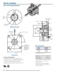
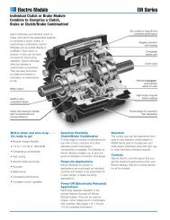
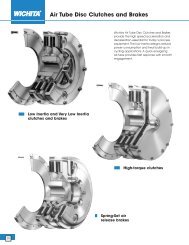
<strong>Air</strong> <strong>Tube</strong> <strong>Disc</strong> <strong>Clutches</strong> <strong>and</strong> <strong>Brakes</strong><br />
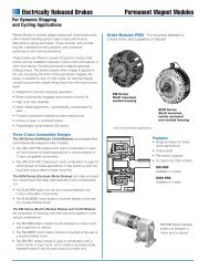
Spring-Set <strong>Air</strong> Release <strong>Brakes</strong><br />
Ring<br />
Very Low<br />
Inertia Drive<br />
Plate Assembly<br />
Bonded or Riveted<br />
Shims<br />
Multiple<br />
Spud <strong>Air</strong>tube<br />
Hub<br />
Ductile<br />
Center Plate<br />
<strong>Air</strong>tube<br />
Holding<br />
Plate<br />
Grooved<br />
Friction <strong>Disc</strong><br />
Demountabl<br />
e Backplate<br />
Wichita Spring-Set <strong>Air</strong> Release <strong>Brakes</strong> are<br />
ideal for fail safe protection of process<br />
equipment. Constructed of high strength<br />
cast iron, this improved design has thick<br />
friction discs for longer wear life. The fast<br />
acting air-tube design assures quick,<br />
smooth stops.<br />
• No lubrication<br />
• No adjustment<br />
• Available in vertical mount<br />
• Quick, simple installation<br />
• Explosion proof design<br />
Selection requirements<br />
The selection of a Low Inertia Brake is<br />
based on:<br />
1. Torque required to stop a load.<br />
2. Friction area necessary to absorb<br />
rotational energy.<br />
3. Contact velocity of rotating discs.<br />
4. Maximum bore capacity of unit.<br />
54
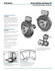
Selection<br />
Low Inertia Spring-Set Brake<br />
To properly select a brake, the total<br />
rotating inertia, WR 2 , must be reflected<br />
to the brakeshaft.<br />
Application Data:<br />
Refer to page 43, except, cyclic operation—<br />
7 rpm, <strong>and</strong> 218 Very Low Inertia Clutch.<br />
Alternate Shaft WR 2 referred to clutch shaft =<br />
(Alternate Shaft WR 2 )<br />
( Alternate Shaft rpm ) 2<br />
Clutch Brake Shaft rpm<br />
WR 2 referred to clutch-brake shaft<br />
= (39,091)<br />
( 30 ) 2<br />
204<br />
WR 2 referrred to clutch-brake shaft<br />
= 845.4 lb.ft. 2 @ 204 rpm<br />
Crank Shaft WR 2 = 845.4 lb.ft. 2<br />
Clutch-Brake Shaft WR 2 = 78.2 lb.ft. 2<br />
Clutch Hub <strong>and</strong> Drive Plate WR 2<br />
from Specification Table = 14.7 lb.ft. 2<br />
(page 57)<br />
Est. Brake WR 2 = 14.7 lb.ft. 2<br />
Est. Total WR 2 = 953.0 lb.ft. 2<br />
Brake Selection:<br />
Stopping angle of crank shaft<br />
=120° = Ø b<br />
Use 90° for calculation<br />
Estimated time to stop:<br />
t =<br />
( ) ( Øb 60<br />
360° crank shaft rpm )<br />
= (<br />
90<br />
) ( 60 ) = .5 sec.<br />
360 30<br />
Deceleration Torque<br />
= (12) (<br />
WR 2 )( clutch-brake rpm )<br />
32.2 (9.5) (t)<br />
= (12) (<br />
953<br />
)(<br />
204<br />
)<br />
32.2 (9.5) (.5)<br />
= 15,250 lb.in.<br />
From duty chart (page 31) “Group B”<br />
for spring set brake (SS):<br />
214 SS Brake is rated @ 28 HP/100 rpm<br />
90% torque rating = 24,800 lb.in.<br />
WR 2 of 214 SS VLI Brake = 4.5 lb.ft. 2 , therefore<br />
deceleration torque calculation is correct.<br />
*Average heat horsepower to clutch & brake.<br />
Ave. heat HP = (Total WR2 ) (rpm 2 ) (cpm)<br />
1.9 x 10 8<br />
= (953) (41,616) (7) = 1.45 HP<br />
1.9 x 10 8<br />
*Check with factory for heat capacity.<br />
Note:<br />
This application example is for<br />
preliminary sizing only. Contact a<br />
Wichita Sales Engineer or the<br />
factory for final selection.<br />
A<br />
B<br />
C<br />
D<br />
E<br />
F<br />
G<br />
HP/100 rpm<br />
= 15,250 = 24 HP/100 rpm<br />
630<br />
H<br />
55
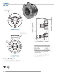
<strong>Air</strong> <strong>Tube</strong> <strong>Disc</strong> <strong>Clutches</strong> <strong>and</strong> <strong>Brakes</strong><br />
Model<br />
Size<br />
ATD-xxx<br />
ATD-xxx<br />
Model No.<br />
Spring-Set <strong>Air</strong> Release <strong>Brakes</strong><br />
(1) For high speed<br />
cyclic duty<br />
(2) Slow speed<br />
cyclic duty<br />
(3) Holding <strong>and</strong><br />
service brakes<br />
Model<br />
Type<br />
LI-SSB for Low Inertia Spring Set Brake<br />
VLI-SSB for Very Low Inertia Spring Set Brake<br />
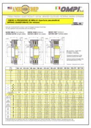
Specifications<br />
Slip Torque Lb. In. .3 CF*<br />
Model<br />
Minimum <strong>Air</strong>-<strong>Tube</strong> Pressure<br />
Size<br />
PSI For Released Brake<br />
ATD- 60 (1) 75(2) 90 (3)<br />
106 2,225 2,900 3,700<br />
206 4,300 5,600 7,200<br />
108 3,700 4,800 6,200<br />
208 7,100 9,100 12,000<br />
111 8,200 10,500 11,600<br />
211 15,600 20,000 26,000<br />
114 14,500 18,600 24,700<br />
214 27,600 35,400 46,300<br />
118 31,400 40,400 51,600<br />
218 60,000 77,000 100,000<br />
124H 75,500 111,000 —<br />
224H 137,000 216,000 —<br />
130H 162,200 211,700 260,500<br />
230H 310,000 404,500 495,500<br />
136 254,500 300,000 400,000<br />
236 477,500 564,000 760,000<br />
142 425,000 — —<br />
242 796,000 — —<br />
148 698,250 — —<br />
248 1,335,000 — —<br />
260 3,255,000 — —<br />
360 4,921,000 — —<br />
* Max. recommended air pressure – 130 PSI<br />
See Application Factor Chart<br />
Max.<br />
Swept Bore <strong>Air</strong> Volume-Inches 3<br />
Model Friction Rect. Recommended<br />
Size Area Key New Worn Clearances<br />
ATD- In 2 Inches Linings Linings Inches<br />
106 39 2 5 12 1/16-3/32<br />
206 78 2 6 12 1/16-3/32<br />
108 56 2-3/8 6 18 1/16-1/8<br />
208 112 2-3/8 7 18 3/32-5/32<br />
111 114 2-5/8 10 30 1/16-1/8<br />
211 228 2-5/8 12 30 3/32-5/32<br />
114 158 4-1/8 15 45 1/16-1/8<br />
214 316 4-1/8 18 45 3/32-5/32<br />
118 264 5-1/4 26 80 1/16-1/8<br />
218 528 5-1/4 30 80 3/32-5/32<br />
124H 574 7 60 165 3/32-5/32<br />
224H 1,148 7 70 165 1/8-3/16<br />
130H 827 8-1/2 100 240 3/32-5/32<br />
230H 1,654 8-1/2 125 240 1/8-3/16<br />
136 1,150 10-1/2 150 375 3/32-5/32<br />
236 2,300 10-1/2 170 375 1/8-3/16<br />
142 1,400 14 180 525 1/8-3/16<br />
242 2,800 14 200 525 5/32-7/32<br />
148 2,010 18 380 925 1/8-3/16<br />
248 4,020 18 450 925 5/32-7/32<br />
260 7,230 19 625 1750 3/16-5/16<br />
360 10,845 19 750 1750 1/4-3/8<br />
Note: Very Low Spring Set <strong>Brakes</strong> are available in sizes from ATD-108 to ATD-224H.<br />
56
A<br />
*Do Not Exceed 90% Of Slip Torque Ratings —<br />
Model<br />
Maximum Horsepower Per 100 RPM Release Pressure - PSI<br />
Size 60 Duty 75 Duty 100 Duty<br />
ATD- A B C D A B C D A B C D<br />
106 3 2.3 1.2 .6 4 3 1.5 .8 5 3.8 2 1<br />
206 6 4.4 2.3 1.1 8 5.7 3 1.5 10 7.4 3.9 2<br />
108 5.3 3.8 2 1 7 5 2.6 1.3 9 6.3 3.3 1.6<br />
208 10 7.3 3.8 2 13 9.3 5 2.5 17 12.3 6.5 3.2<br />
111 11.7 8.4 4.4 2.2 15 10.7 5.7 2.8 16.6 12 6.3 3.1<br />
211 22 16 8.4 4.2 28.6 20.5 11 5.4 37 26 14 7<br />
114 20 15 8 4 26.6 19 10 5 35 25 13 6.7<br />
214 39 28 15 7.5 50 36 19 9.5 66 47 25 12.5<br />
118 45 32 17 8.5 58 41 22 11 74 53 28 14<br />
218 86 61 32 16 110 79 41 21 143 102 54 27<br />
124H 108 77 41 20 158 114 60 30 183 131 69 34<br />
224H 196 140 74 37 308 222 117 58 346 248 131 65<br />
130H 232 166 88 44 303 217 115 57 372 267 141 70<br />
230H 443 318 167 84 578 415 218 110 710 508 268 134<br />
136 363 260 137 68 660 475 250 125 — — — —<br />
236 560 400 210 105 1050 755 400 200 — — — —<br />
142 610 435 230 115 — — — — — — — —<br />
242 1140 815 430 215 — — — — — — — —<br />
148 1000 715 375 190 — — — — — — — —<br />
248 1910 1370 720 360 — — — — — — — —<br />
260 4650 2340 1760 880 — — — — — — — —<br />
360 7030 4050 2660 1330 — — — — — — — —<br />
B<br />
C<br />
D<br />
Low Inertia Spring Set<br />
Very Low Inertia Spring Set<br />
HUB HUB HUB HUB<br />
Model Total & CP & CP Effec. Total & DP & DP Effec.<br />
Size Wt. Wt. WR 2 Wt† Wt. Wt. WR 2 Wt.†<br />
ATD- Lbs. Lbs. #Ft. 2 Lbs. Lbs. Lbs. #Ft. 2 Lbs.<br />
106 36.5 6.40 .24 14.0 — — — —<br />
206 49.5 12.17 .46 18.34 — — — —<br />
108 63.23 10.0 .55 26.78 59.14 6.7 .24 16.53<br />
208 81.5 16.0 .72 32.03 77.16 12.9 .44 24.06<br />
111 96.96 15.0 1.35 40.75 97.55 9.6 .59 47.55<br />
211 136.0 30.0 2.60 59.05 133.3 18.6 1.15 66.35<br />
114 157.6 38 5.6 72.3 156.6 20.4 2.25 77.3<br />
214 209.6 65 11 95.3 211.6 39.8 4.44 105.3<br />
118 322 71 14.5 168 316.4 40.0 7.7 147<br />
218 444 113 27.6 215 420.6 75.0 14.7 233<br />
124H 690 131 50 377 657.5 84.0 28.5 365<br />
224H 874 260 101 482 818 150 54.9 459<br />
130H 1089 212 129 630 — — — —<br />
230H 1450 402 244 849 — — — —<br />
136 1814 351 325 1127 — — — —<br />
236 2780 784 705 1444 — — — —<br />
142 2994 680 705 1389 — — — —<br />
242 3601 1197 1385 1784 — — — —<br />
148 5070 1101 1785 2740 — — — —<br />
248 6501 1942 3335 3426 — — — —<br />
260 11549 2567 7077 5836 — — — —<br />
360 13739 3870 10615 6318 — — — —<br />
† Weight of internal clutch parts for use in calculating clutch engagement time.<br />
E<br />
F<br />
G<br />
H<br />
57
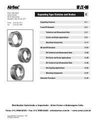
<strong>Air</strong> <strong>Tube</strong> <strong>Disc</strong> <strong>Clutches</strong> <strong>and</strong> <strong>Brakes</strong><br />
Spring-Set <strong>Air</strong> Release <strong>Brakes</strong><br />
Demountable Backplate<br />
a - Number of holes<br />
b - Hole size<br />
A<br />
B<br />
C<br />
E<br />
D<br />
H<br />
I<br />
J<br />
Z<br />
j<br />
k<br />
V<br />
Spring Set<br />
U<br />
i<br />
Y<br />
O<br />
Low inertia Very low inertia<br />
g - Tap<br />
f = No. of<br />
Holes<br />
(See Note)<br />
3<br />
2<br />
4<br />
1<br />
6A<br />
7<br />
Component Parts<br />
1. Hub<br />
2. Backplate<br />
3. Socket Head<br />
Capscrews<br />
4. Ring<br />
6B<br />
7<br />
6A<br />
5. Springs<br />
6A. Grooved Friction<br />
<strong>Disc</strong> (grooved on<br />
one side)<br />
6B. Grooved Friction<br />
<strong>Disc</strong> (grooved on<br />
both sides)<br />
7. Center Plate<br />
11. <strong>Air</strong>tube<br />
12. O. D. Shims<br />
13. <strong>Air</strong> <strong>Tube</strong> Holding<br />
Plate<br />
14. Socket Head<br />
Capscrews<br />
15. I.D. Shims<br />
16. Spring Release<br />
Plate<br />
17. <strong>Air</strong>tube Spring Plate<br />
A<br />
B<br />
C<br />
12<br />
16<br />
18. Socket Head<br />
Capscrews<br />
D<br />
Dimensions<br />
F<br />
G<br />
(Consult factory for drawing before final layout.)<br />
W<br />
X<br />
c - Number of holes<br />
d - Tap<br />
Note: <strong>Air</strong> Hose Kits, see page 60.<br />
5<br />
17<br />
14<br />
11<br />
15<br />
13<br />
18<br />
E<br />
Model<br />
No. ATD- A B C D E F G H I J O U<br />
106 8.75 8.000 7.377/7.379 4.19 .06 .562 .69 7.373/7.375 8.000 7.377/7.379 8.81 —<br />
206 8.75 8.000 7.377/7.379 4.19 .06 .562 .69 7.373/7.375 8.000 7.377/7.379 8.81 —<br />
108 12.12 11.125 8.375/8.378 5.38 .25 .875 1.00 9.281/9.284 10.187 9.285/9.288 11.13 5.06<br />
208 12.12 11.125 8.375/8.378 5.38 .25 .875 1.00 9.281/9.284 10.187 9.285/9.288 11.13 6.31<br />
111 16.00 14.750 11.375/11.378 7.00 .38 1.125 1.25 12.370/12.373 13.500 12.375/12.378 14.75 5.00<br />
211 16.00 14.750 11.375/11.378 7.00 .38 1.125 1.25 12.370/12.373 13.500 12.375/12.378 14.75 7.06<br />
114 18.75 17.500 14.375/14.378 9.43 .38 1.125 1.25 15.121/15.124 16.250 15.125/15.128 17.50 6.81<br />
214 18.75 17.500 14.375/14.378 9.43 .38 1.125 1.25 15.121/15.124 16.250 15.125/15.128 17.50 8.69<br />
118 23.25 22.000 18.250/18.253 12.50 .38 1.125 1.25 19.495/19.498 20.750 19.500/19.503 22.00 7.44<br />
218 23.25 22.000 18.250/18.253 12.50 .38 1.125 1.25 19.495/19.498 20.750 19.500/19.503 22.00 9.69<br />
124H 30.00 28.750 24.375/24.378 14.50 .25 1.125 1.25 25.497/25.499 26.750 25.500/25.503 29.00 8.38<br />
224H 30.00 28.750 24.375/24.378 14.50 .25 1.125 1.25 25.497/25.499 26.750 25.500/25.503 29.00 10.93<br />
130H 37.00 35.500 30.375/30.378 19.25 .25 1.250 1.43 32.118/32.123 33.250 32.125/32.128 34.75 —<br />
230H 37.00 35.500 30.375/30.378 19.25 .25 1.250 1.43 32.118/32.123 33.250 32.125/32.128 34.75 —<br />
136 43.50 42.000 36.375/36.378 23.63 .25 1.500 1.75 38.120/38.123 39.500 38.125/38.128 41.00<br />
236 43.50 42.000 36.375/36.378 23.63 .25 1.500 1.75 38.120/38.123 39.500 38.125/38.128 41.00 —<br />
142 52.00 49.250 44.625/44.628 29.50 .25 1.500 1.75 44.995/44.998 46.500 45.000/45.003 49.00 —<br />
242 52.00 49.250 44.625/44.628 29.50 .25 1.500 1.75 44.995/44.998 46.500 45.000/45.003 49.00 —<br />
148 61.00 58.000 52.000/52.005 32.00 .25 1.500 1.75 51.993/51.998 54.000 52.000/52.005 56.75 —<br />
248 61.00 58.000 52.000/52.005 32.00 .25 1.500 1.75 51.993/51.998 54.000 52.000/52.005 56.75 —<br />
260 62.750/62.760 36.00 .25 62.740/62.745 66.500 62.750/62.760 70.50 —<br />
360 62.750/62.760 36.00 .25 62.740/62.745 66.500 62.750/62.760 70.50 —<br />
Notes: Very Low Inertia Spring Set <strong>Brakes</strong> are available in sizes from ATD-108 to ATD-224H. See page 34.<br />
For mounting, use socket head cap screws conforming to the ASTM-574-97a.<br />
Model<br />
No. ATD- V W X Y Z a b c d f g j k<br />
106 — 3.56 4.88 2.00 .06 4 11/32 4 5/16-18 2 1/4"NPT .69 2.00<br />
206 — 4.69 6.19 2.00 .06 4 11/32 4 5/16-18 1/4"NPT .69 3.25<br />
108 3.81 3.69 4.94 1.95 .13 6 17/32 6 1/2-13 2 1/2" NPT .50 1.50<br />
208 5.06 4.88 6.13 1.95 .13 6 17/32 6 1/2-13 1/2" NPT .50 2.87<br />
111 4.00 3.94 5.25 3.02 .13 6 21/32 6 5/8-11 2 1/2" NPT .75 2.00<br />
211 5.75 5.63 6.63 3.02 .13 6 21/32 6 5/8-11 1/2" NPT .75 3.75<br />
114 4.63 4.56 6.63 3.88 .13 8 21/32 8 5/8-11 2 1/2" NPT .88 2.25<br />
214 6.69 6.56 8.56 3.88 .13 8 21/32 8 5/8-11 1/2" NPT .88 4.25<br />
118 5.13 5.63 7.88 4.88 .13 12 21/32 12 5/8-11 3 1/2" NPT .81 2.75<br />
218 7.44 7.31 9.56 4.88 .13 12 21/32 12 5/8-11 1/2" NPT .81 4.75<br />
124H 6.13 5.88 8.13 8.25 .13 12 21/32 12 5/8-11 3 1/2" NPT .56 3.13<br />
224H 8.50 8.38 10.81 8.25 .13 12 21/32 12 5/8-11 1/2" NPT .56 5.13<br />
130H — 7.13 10.00 8.25 .19 18 25/32 18 3/4-10 4 1/2" NPT .88 5.00<br />
230H — 10.38 13.25 8.25 .19 18 25/32 18 3/4-10 1/2" NPT .88 7.13<br />
136 — 7.00 11.19 12.75 .19 18 25/32 18 3/4-10 4 1/2" NPT .88 4.25<br />
236 — 10.25 14.44 12.75 .19 18 25/32 18 3/4-10 1/2" NPT .88 7.50<br />
142 — 8.38 11.25 20.50 .25 24 1-1/32 24 1-8 4 1/2" NPT .75 5.62<br />
242 — 12.13 15.00 20.50 .25 24 1-1/32 24 1-8 1/2" NPT .75 7.50<br />
148 — 9.56 13.93 19.00 .25 24 1-1/32 24 1-8 4 1/2" NPT1 .00 6.00<br />
248 — 13.88 18.25 19.00 .25 24 1-1/32 24 1-8 1/2" NPT1 .00 8.75<br />
260 — 17.75 22.38 20.63 .25 24 2" NC 24 2-4-1/2 6 1/2" NPT1 .00 9.37<br />
360 — 22.25 26.88 20.63 .25 24 2" NC 24 2-4-1/2 1/2" NPT1 .00 14.13<br />
F<br />
G<br />
H<br />
58<br />
59
<strong>Air</strong> <strong>Tube</strong> <strong>Disc</strong> <strong>Clutches</strong> <strong>and</strong> <strong>Brakes</strong><br />
<strong>Air</strong> Hose Kits<br />
Model<br />
Part Number<br />
8" 8-908-912-100-5<br />
8-908-924-100-5 QRV<br />
Model<br />
Part Number<br />
6" 8-906-912-200-4<br />
8-906-931-201-5 QRV<br />
8" 8-908-913-200-5<br />
8-908-931-200-5<br />
11" 8-911-913-200-5<br />
8-911-931-200-5 QRV<br />
14" 8-914-913-200-5<br />
8-914-921-200-5 QRV<br />
16" 8-916-913-200-5<br />
8-916-921-200-5 QRV<br />
Model<br />
Part Number<br />
18" 8-918-912-200-5<br />
8-918-931-200-5 QRV<br />
21" 8-921-913-200-5<br />
8-921-931-200-5 QRV<br />
24" 8-924-913-200-5<br />
8-924-931-200-5 QRV<br />
27" 8-927-913-200-5<br />
8-927-921-200-5 QRV<br />
<strong>Air</strong> hose kits contain all<br />
necessary parts (fittings,<br />
hoses <strong>and</strong> extensions) to<br />
completely plumb the<br />
brake air system.<br />
Model<br />
Part Number<br />
30" 8-930-913-400-5<br />
8-930-931-400-5 QRV<br />
36" 8-936-913-400-6<br />
8-936-931-400-6 QRV<br />
42" 8-942-913-400-6<br />
8-924-931-400-6 QRV<br />
48" 8-948-912-400-6<br />
8-948-923-400-6 QRV<br />
Model<br />
Part Number<br />
60" 8-960-912-500-5<br />
8-960-923-400-6 QRV<br />
Optional Quick Release<br />
Valves can replace elbows<br />
on most units (see page 61).<br />
Roto-couplings<br />
(see page 61).<br />
60<br />
Distribuidor Autorizado e Importador - <strong>Arten</strong> <strong>Freios</strong> e <strong>Embreagens</strong> Ltda.<br />
Fone: (11) 5594-8333 • Fax (11) 5589-2422 - arten@arten.com.br • www.arten.com.br