HFM-301/305 HFC-303/307 - Teledyne Hastings Instruments
HFM-301/305 HFC-303/307 - Teledyne Hastings Instruments
HFM-301/305 HFC-303/307 - Teledyne Hastings Instruments
- No tags were found...

You also want an ePaper? Increase the reach of your titles
YUMPU automatically turns print PDFs into web optimized ePapers that Google loves.
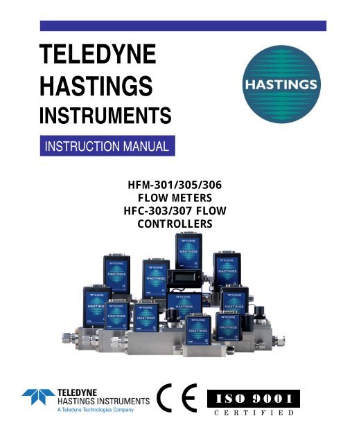
TELEDYNE<br />
HASTINGS<br />
INSTRUMENTS<br />
INSTRUCTION MANUAL<br />
<strong>HFM</strong>-<strong>301</strong>/<strong>305</strong>/306<br />
FLOW METERS<br />
<strong>HFC</strong>-<strong>303</strong>/<strong>307</strong> FLOW<br />
CONTROLLERS<br />
ISO 9001<br />
C E R T I F I E D
Manual Print History<br />
The print history shown below lists the printing dates of all revisions and addenda created for this<br />
manual. The revision level letter increases alphabetically as the manual undergoes subsequent updates.<br />
Addenda, which are released between revisions, contain important change information that the user<br />
should incorporate immediately into the manual. Addenda are numbered sequentially. When a new<br />
revision is created, all addenda associated with the previous revision of the manual are incorporated into<br />
the new revision of the manual. Each new revision includes a revised copy of this print history page.<br />
Revision F (Document Number 152-082002)................................................................. August 2002<br />
Revision G (Document Number 152-102002) .............................................................. October 2002<br />
Revision H (Document Number 152-082005) ................................................................ August 2005<br />
Revision J (Document Number 152-042006)...................................................................March 2006<br />
Revision K (Document Number 152-062008) ....................................................................June 2008<br />
Revision L (Document Number 152-082008)................................................................. August 2008<br />
Revision M (Document Number 152-082009)................................................................ August 2009<br />
Revision N (Document Number 152-102009) .............................................................. October 2009<br />
Revision P (Document Number 152-082010)................................................................. August 2010<br />
Visit www.teledyne-hi.com for WEEE disposal guidance.<br />
CAUTION:<br />
The instruments described in this manual are available with multiple pin-outs.<br />
Ensure that all electrical connections are correct.<br />
CAUTION:<br />
The instruments described in this manual are designed for INDOOR use only.<br />
CAUTION:<br />
The instruments described in this manual are designed for Class 2 installations<br />
in accordance with IAW/IPC standards<br />
<strong>Hastings</strong> <strong>Instruments</strong> reserves the right to change or modify the design of its equipment without<br />
any obligation to provide notification of change or intent to change.<br />
Manual: 152-082010 <strong>301</strong>-<strong>305</strong>-306_<strong>303</strong>-<strong>307</strong> Series Page 2 of 35
Table of Contents<br />
1. GENERAL INFORMATION............................................................................................................................................ 4<br />
1.1. FEATURES.................................................................................................................................................................... 4<br />
1.2. SPECIFICATIONS........................................................................................................................................................... 5<br />
1.3. OPTIONAL 4-20 MA CURRENT OUTPUT ....................................................................................................................... 6<br />
1.4. OTHER ACCESSORIES................................................................................................................................................... 6<br />
2. OPERATION...................................................................................................................................................................... 7<br />
2.1. RECEIVING INSPECTION ............................................................................................................................................... 7<br />
2.2. POWER REQUIREMENTS ............................................................................................................................................... 7<br />
2.3. OUTPUT SIGNAL........................................................................................................................................................... 7<br />
2.4. MECHANICAL CONNECTIONS....................................................................................................................................... 7<br />
2.5. ELECTRICAL CONNECTIONS......................................................................................................................................... 8<br />
2.6. 4 – 20 MA CONNECTIONS........................................................................................................................................... 11<br />
2.7. OPERATION................................................................................................................................................................ 12<br />
2.8. RANGE CHANGING..................................................................................................................................................... 16<br />
2.9. OUTPUT FILTER ......................................................................................................................................................... 16<br />
2.10. CONTROLLING OTHER PROCESS VARIABLES ............................................................................................................. 16<br />
2.11. COMMAND INPUT....................................................................................................................................................... 16<br />
2.12. VALVE OVERRIDE CONTROL ..................................................................................................................................... 17<br />
2.13. GAIN POTENTIOMETER .............................................................................................................................................. 17<br />
2.14. TEMPERATURE COEFFICIENTS ................................................................................................................................... 18<br />
3. THEORY AND FUNCTION ........................................................................................................................................... 19<br />
3.1. OVERALL FUNCTIONAL DESCRIPTION........................................................................................................................ 19<br />
3.2. SENSOR DESCRIPTION................................................................................................................................................ 19<br />
3.3. SENSOR THEORY........................................................................................................................................................ 19<br />
3.4. BASE.......................................................................................................................................................................... 20<br />
3.5. SHUNT DESCRIPTION .................................................................................................................................................. 21<br />
3.6. SHUNT THEORY ......................................................................................................................................................... 21<br />
3.7. CONTROL VALVE....................................................................................................................................................... 23<br />
3.8. ELECTRONIC CIRCUITRY............................................................................................................................................ 24<br />
3.9. INSTRUMENT PERFORMANCE ..................................................................................................................................... 24<br />
4. MAINTENANCE.............................................................................................................................................................. 25<br />
4.1. AUTHORIZED MAINTENANCE..................................................................................................................................... 25<br />
4.2. TROUBLESHOOTING ................................................................................................................................................... 25<br />
4.3. ADJUSTMENTS ........................................................................................................................................................... 26<br />
4.4. END CAP REMOVAL................................................................................................................................................... 27<br />
4.5. PRINTED CIRCUIT BOARD AND SENSOR REPLACEMENT............................................................................................. 28<br />
5. OUTLINE DRAWINGS .................................................................................................................................................. 29<br />
5.1. <strong>HFM</strong>-<strong>301</strong>................................................................................................................................................................... 29<br />
5.2. <strong>HFC</strong>-<strong>303</strong> ................................................................................................................................................................... 29<br />
5.3. <strong>HFM</strong>-<strong>305</strong>................................................................................................................................................................... 30<br />
5.4. <strong>HFM</strong>-306................................................................................................................................................................... 30<br />
5.5. <strong>HFC</strong>-<strong>307</strong> ................................................................................................................................................................... 31<br />
6. WARRANTY .................................................................................................................................................................... 32<br />
6.1. WARRANTY REPAIR POLICY ...................................................................................................................................... 32<br />
6.2. NON-WARRANTY REPAIR POLICY ............................................................................................................................. 32<br />
7. APPENDIX ....................................................................................................................................................................... 33<br />
7.1. APPENDIX 1- VOLUMETRIC VERSUS MASS FLOW....................................................................................................... 33<br />
7.2. APPENDIX 2 - GAS CONVERSION FACTORS ................................................................................................................ 34<br />
Manual: 152-082010 <strong>301</strong>-<strong>305</strong>-306_<strong>303</strong>-<strong>307</strong> Series Page 3 of 35
1. General Information<br />
The <strong>Hastings</strong> 300 Series high range mass flow meters are designed to accurately measure mass flow at a<br />
range between 25 slm and 10000 slm. The <strong>Hastings</strong> 300 Series high range mass flow controllers are<br />
designed to accurately measure and control mass flow at a range between 25 slm and 2500 slm. These<br />
instruments are intrinsically linear and have an accuracy of better than ±1% F.S. (full scale).<br />
<strong>Hastings</strong> mass flow instruments do not require any periodic maintenance under normal operating<br />
conditions with clean gases. No damage will occur from the use of moderate overpressures (~500<br />
psi/3.45MPa) or overflows. <strong>Instruments</strong> are normally calibrated with the appropriate standard calibration<br />
gas (nitrogen) then a correction factor is used to adjust the output for the intended gas. Calibrations for<br />
other gases, such as oxygen, helium and argon, are available upon special order.<br />
1.1. Features<br />
• LINEAR BY DESIGN. The <strong>HFM</strong>-<strong>301</strong>/<strong>305</strong>/306 and <strong>HFC</strong>-<strong>303</strong>/<strong>307</strong> series is intrinsically linear (no<br />
linearization circuitry is employed). Should recalibration (a calibration standard is required) in the<br />
field be desired, the customer needs to simply set the zero and span points. There will be no<br />
appreciable linearity change of the instrument when the flowing gas is changed.<br />
• NO FOLD OVER. The output signal is linear for very large over flows and is monotonically increasing<br />
thereafter. The output signal will not come back on scale when flows an order of magnitude over<br />
the full scale flow rate are measured. This means no false acceptable readings during leak testing.<br />
• MODULAR SENSOR. The <strong>HFM</strong>-<strong>301</strong>/<strong>305</strong>/306 and <strong>HFC</strong>-<strong>303</strong>/<strong>307</strong> series incorporates a<br />
removable/replaceable sensor module. Field repairs to units can be achieved with a minimum of<br />
production line downtime. Calibration is required.<br />
• FAST SETTLING TIME. Changes in flow rate are detected in less than 500 milli-seconds when using<br />
the standard factory PC board settings. Controller response is typically < 2 seconds.<br />
• LOW TEMPERATURE DRIFT. The temperature coefficient of span for the <strong>HFM</strong>-<strong>301</strong>/<strong>HFC</strong>-<strong>303</strong> series is<br />
less than 0.092% of full scale/°C from 0-60°C. The temperature coefficient of zero is less than 0.085<br />
% of reading/°C from 0-60°C.<br />
• FIELD RANGEABLE. The <strong>HFM</strong>-<strong>305</strong> and <strong>HFC</strong>-<strong>307</strong> are available in ranges from 1000 slm to 2500 slm.<br />
The <strong>HFM</strong>-<strong>301</strong> and <strong>HFC</strong>-<strong>303</strong> are available from 25-1000 slm. Each flow meter has a shunt and<br />
transducer which can be exchanged in the field to select different ranges. Calibration, however, is<br />
required.<br />
• CURRENT LOOP. The 4-20 mA option gives the user the advantages of a current loop output to<br />
minimize environmental noise pickup.<br />
Manual: 152-082010 <strong>301</strong>-<strong>305</strong>-306_<strong>303</strong>-<strong>307</strong> Series Page 4 of 35
1.2. Specifications<br />
Accuracy..........................................................<strong>HFM</strong>-<strong>301</strong>/<strong>305</strong> & <strong>HFC</strong>-<strong>303</strong>/<strong>307</strong>: ±1% full scale (F.S.)<br />
...........................................................................................................<strong>HFM</strong>-306; ±3% full scale (F.S.)<br />
Repeatability ................................................................................................................ ±0.07% of F.S.<br />
Maximum pressure................................................................................................500 psi [3.45 MPa]<br />
..............................................................................................................................300 psi (<strong>HFM</strong>-306)<br />
Maximum pressure................................................................................................1000 psi [6.9 MPa]<br />
..................................................................... (with high pressure option on <strong>HFM</strong>-<strong>301</strong>/<strong>HFC</strong><strong>303</strong> only)<br />
Pressure coefficient.................................................................................
1.3. Optional 4-20 mA Current Output<br />
An option to the standard 0 - 5 VDC output is the 4 - 20 mA current output that is proportional to flow.<br />
The 4 - 20 mA signal is produced from the 0 - 5 VDC output of the flow meter. The current loop output is<br />
useful for remote applications where pickup noise could substantially affect the stability of the voltage<br />
output.<br />
The current loop signal replaces the voltage output on pin 6 of the “D” connector. The load must be less<br />
than 600Ω. Failure to meet this condition will cause failure of the loop transmitter.<br />
1.4. Other Accessories<br />
1.4.1. <strong>Hastings</strong> Power supplies<br />
<strong>Hastings</strong> Power Pod power supply/display units are available in one and four channel versions. They<br />
convert 100, 115 or 230VAC to the ±15 VDC required to operate the flow meter and provide a digital<br />
indication of the flow rate. Interface terminals for the retransmission of the flow meter analog output<br />
signal are located on the rear of the panel.<br />
The Power Pod 100 and 400 models are built with controllers in mind but will work with meters as well.<br />
The Model 40 is for flow meters only. Throughout this manual, when reference is made to a power<br />
supply, it is assumed the customer is using a <strong>Hastings</strong> power supply. <strong>Hastings</strong> PowerPod-100 and<br />
PowerPod-400 power supplies are CE marked, but the Model 40 does not meet CE standards at this time.<br />
The Model 40 and PowerPod-100 are not compatible with 4–20 mA analog signals. With the PowerPod<br />
400, individual channels’ input signals, as well as their commands, become 4–20 mA compatible when<br />
selected. The PowerPod-400 also sports a Totalizer feature. More information about the Power Pods can<br />
be found on the <strong>Hastings</strong> web site. http://www.teledyne-hi.com/products/powerpod-series.htm<br />
1.4.2. Interconnecting Cables<br />
Cables are available from <strong>Hastings</strong>, in various lengths, to connect from the 15 pin "D" connector on the<br />
back of the Power Pod directly to any of the 200 series and 300 series flow instruments (including digital<br />
versions). More information about the available cables can be found in the Power Pod 400 bulletin on<br />
the <strong>Hastings</strong> web site. http://www.teledyne-hi.com/pdfs/bulletins.htm<br />
The 300 series flow instruments normally come with the standard “H” pin-out connector. This type of<br />
connector is supplied on the <strong>Hastings</strong> AF-8-AM series cables with grey backshells (such as #65-149). “U”<br />
pin-out versions of the 300 series instruments require a different cable to connect to the power supply.<br />
This cable is identifiable by black back-shells and is available as <strong>Hastings</strong> Instrument (#65-791)<br />
Manual: 152-082010 <strong>301</strong>-<strong>305</strong>-306_<strong>303</strong>-<strong>307</strong> Series Page 6 of 35
2. Operation<br />
This section contains the necessary steps to assist in getting a new flow meter/controller into operation<br />
as quickly and easily as possible. Please read the following thoroughly before attempting to install the<br />
instrument.<br />
2.1. Receiving Inspection<br />
Carefully unpack the <strong>Hastings</strong> 300 Series instrument and any accessories that have also been ordered.<br />
Inspect for any obvious signs of damage to the shipment. Immediately advise the carrier who delivered<br />
the shipment if any damage is suspected. Check each component shipped with the packing list. Insure<br />
that all parts are present (i.e., flow meter, power supply, cables, etc.). Optional equipment or<br />
accessories will be listed separately on the packing list. There may also be one or more OPT-options on<br />
the packing list. These normally refer to special ranges or special gas calibrations. They may also refer<br />
to special helium leak tests, or high pressure tests. In most cases, these are not separate parts, but<br />
special options or modifications built into the flow meter.<br />
Quick Start<br />
1. Insure flow circuit mechanical connections are leak free.<br />
2. Insure electrical connections are correct (See label).<br />
3. Power up. (Allow 30 minutes to 1 hour warm-up for best accuracy.)<br />
4. Note the flow signal decays toward zero.<br />
5. Run ~20% flow (~ 1 VDC) through instrument for 5 minutes.<br />
6. Insure zero flow; wait 2 minutes, then zero the instrument.<br />
7. Instrument is ready for operation.<br />
2.2. Power Requirements<br />
The <strong>HFM</strong>-<strong>301</strong>/<strong>305</strong>/306 requires ±15 VDC @ 55 mA. The <strong>HFC</strong>-<strong>303</strong>/<strong>307</strong> requires ±15VDC @ 150 mA for<br />
proper operation. The supply voltage should be sufficiently regulated to no more than 50 mV ripple.<br />
The supply voltage can vary from 14.0 to 16.0 VDC. Surge suppressors are recommended to prevent<br />
power spikes reaching the instrument. The <strong>Hastings</strong> power supply described in Section Error! Reference<br />
source not found. satisfies these power requirements.<br />
2.3. Output Signal<br />
The standard output of the flow meter is a 0 - 5 VDC signal proportional to the flow rate. In the <strong>Hastings</strong><br />
power supply the output is routed to the display and is also available at the terminals on the rear panel.<br />
If a <strong>Hastings</strong> supply is not used, the output is available on pin 6 of the “D” connector. It is recommended<br />
that the load resistance be no less that 2 kΩ. If the optional 4 - 20 mA output is used, the load<br />
impedance must be less than 600 Ω.<br />
2.4. Mechanical Connections<br />
The flow meter may be mounted in any position as long as the direction of gas flow through the<br />
instrument follows the arrow marked on the bottom of the flow meter case label. The preferred<br />
orientation is with the inlet and outlet fittings in a horizontal plane. If operating with a dense gas (e.g.<br />
Manual: 152-082010 <strong>301</strong>-<strong>305</strong>-306_<strong>303</strong>-<strong>307</strong> Series Page 7 of 35
sulfur hexafluoride) or at high pressures (> 250 psig) the instrument must be installed horizontally.<br />
When mounted in a different orientation the instrument should be re-zeroed at zero flow with the<br />
system pressurized to the expected operating pressure.<br />
One of the smallest of the internal passageways in the 300 Series is the diameter of the sensor tube,<br />
which can be 0.026” (0.66 mm), 0.017” (0.43mm), or 0.014” (0.36mm), so the instrument requires<br />
adequate filtering of the gas supply to prevent blockage or clogging of the tube.<br />
The pressure regulator and the plumbing upstream must be of sufficient size to minimize changes in the<br />
upstream pressure. When switching from full flow to zero flow, the inlet pressure of instrument should<br />
rise to no more that 30% above the inlet pressure at full flow. In general, high capacity regulators and<br />
large internal diameter plumbing help to make the system more stable. The pressure drop between the<br />
regulator and the instrument due to line resistance should be minimized.<br />
There are two threaded holes located on the bottom of the base that can be used to secure it to a<br />
mounting bracket, if desired. Other holes for special mounting can be added if desired.<br />
The optional inlet and outlet fittings for the <strong>301</strong>/<strong>303</strong> are 0.5”, 0.75” Swagelok, 0.5” VCR and 0.5” VCO<br />
fittings. The O-rings for the end cap are Viton (optional Kalrez, Neoprene or Buna-N). The <strong>HFM</strong>-<strong>305</strong> and<br />
<strong>HFC</strong>-<strong>307</strong> are provided with 1” Swagelok, VCR or VCO fittings. The <strong>HFM</strong>-306 can have 1” or 2” Swagelok<br />
fittings. It is suggested that all connections be checked for leaks after installation. This can be done by<br />
pressurizing the instrument (do not exceed pressure rating of the instrument) and applying a diluted<br />
soap solution to the flow connections.<br />
2.5. Electrical Connections<br />
DANGER: Care must be taken to avoid high voltages that may be present when dealing<br />
with power supplies.<br />
If a power supply from <strong>Hastings</strong> <strong>Instruments</strong> is used, installation consists of connecting the 300 Series<br />
cable from the “D” connector on the rear of the power supply to the “D” connector on the top of the<br />
flow meter/controller. The “H” pin-out requires cable AF-8-AM (grey molded back shell). The “U” pinout<br />
requires cable # 65-791 (black molded back shell).<br />
If a different power supply is used, follow the instructions below when connecting the flow meter and<br />
refer to either table 2.1 or 2.2 for the applicable pin-out. The power supply used must be bipolar and<br />
capable of providing ±15 VDC at 55 mA for flow meter applications and ±15 VDC at 150 mA for<br />
controllers. These voltages must be referenced to a common ground. One of the “common” pins of the<br />
<strong>Hastings</strong> instrument must be connected to the common terminal of the power supply. Case ground of<br />
the instrument should be connected to the AC ground locally. The cable shield (if available) should be<br />
connected to AC ground at the either the power supply end, or the instrument end of the cable, not at<br />
both. Pin 6 is the output signal from the flow meter. The standard output will be 0 to 5 VDC, where 5<br />
VDC is 100% of the rated or full scale flow.<br />
The command (set point) input should be a 0 - 5 VDC signal (or 4 - 20mA if configured as such), and must<br />
be free of spikes or other electrical noise, as these would generate false flow commands that the<br />
controller would attempt to follow. The command signal should be referenced to signal common.<br />
A valve override command is available to the flow controller. Connect the center pin of a single pole,<br />
three-position switch (center off) to the override pin. Connect +15 VDC to one end of the three position<br />
switch, and -15 VDC to the other end. The valve will be forced full open when +15 VDC is supplied to the<br />
override pin, and full closed when -15 VDC is applied. When there is no connection to the pin (the<br />
three-position switch is centered) the valve will be in auto control, and will obey the 0 - 5 VDC<br />
commands supplied to command (set-point) input.<br />
Figure 2-1 and Table 2-1 show the 300 Series “H” pin out.<br />
Figure 2-2 and Table 2-2 show the 300 Series U” pin out.<br />
Manual: 152-082010 <strong>301</strong>-<strong>305</strong>-306_<strong>303</strong>-<strong>307</strong> Series Page 8 of 35
Figure 2-1<br />
Table 2-1<br />
“H” Pin-out<br />
Pin<br />
#<br />
1 Do not use<br />
2 Do not use<br />
3 Do not use<br />
4 Do not use<br />
5 Signal Common<br />
6 Output 0-5 VDC (4-20mA)<br />
7 Case Ground<br />
8 Valve Override<br />
9 -15 VDC<br />
10 Do not use<br />
11 +15 VDC<br />
12 Signal Common<br />
13 External Input<br />
14 Set Point 0-5 VDC (4-20mA)<br />
15 Do not use<br />
Manual: 152-082010 <strong>301</strong>-<strong>305</strong>-306_<strong>303</strong>-<strong>307</strong> Series Page 9 of 35
Figure 2-2<br />
Table 2-2<br />
“U” Pin-out<br />
Pin<br />
#<br />
1 Signal Common<br />
2 Do not use<br />
3 Do not use<br />
4 +15 VDC<br />
5<br />
6 Output 0-5 VDC (4-20mA)<br />
7 Signal Common<br />
8 Case Ground<br />
9 Valve Override<br />
10<br />
11 -15 VDC<br />
12 External Input<br />
13 Signal Common<br />
14 Signal Common<br />
15 Set Point 0-5 VDC (4-20mA)<br />
Manual: 152-082010 <strong>301</strong>-<strong>305</strong>-306_<strong>303</strong>-<strong>307</strong> Series Page 10 of 35
2.6. 4 – 20 mA Connections<br />
The 300 Series flow meters have a 4 - 20 mA current output option available as an alternative to the<br />
standard 0 - 5 VDC output. This current output is useful for remote applications where noise pick-up<br />
could substantially affect the stability of the voltage output. The 4 - 20 mA signal is produced from the 0<br />
- 5 VDC output of the flow meter and replaces the voltage output on pin 6 of the “D” connector. The<br />
current is sourced by the flow controller and the metering circuit must sink the current, such that the<br />
current loop is completed through power supply common connections. The load must be less than 600<br />
Ohms. Failure to meet this condition will cause failure of the loop transmitter.<br />
The 300 Series flow controllers have a 4 – 20 mA current input option available as an alternative to the<br />
standard 0 – 5 VDC command input. The controller sinks the input current through a 77 Ohm load to<br />
power supply common.<br />
Power<br />
Supply<br />
+<br />
− +<br />
−<br />
Ground<br />
+15 VDC<br />
−15 VDC<br />
Common<br />
PLC or Analog I/O Card<br />
Pin 7<br />
<strong>Hastings</strong> Flow controller<br />
Pin−out H<br />
Power In<br />
Pin 11<br />
Pin 9<br />
Pin 5,12<br />
Analog Out<br />
Setpoint Input, Pin 14<br />
77 Ohms<br />
0−600 Ohms<br />
Analog In<br />
Analog Return<br />
Analog Output, Pin 6<br />
Figure 2-3<br />
Manual: 152-082010 <strong>301</strong>-<strong>305</strong>-306_<strong>303</strong>-<strong>307</strong> Series Page 11 of 35
2.7. Operation<br />
The standard instrument output is a 0 - 5 VDC and the signal is proportional to the flow i.e., 0 volts =<br />
zero flow and 5 volts = 100% of rated flow. The 4 - 20 mA option is also proportional to flow, 4 mA =<br />
zero flow and 20 mA = 100% of rated flow.<br />
2.7.1. Operating Conditions<br />
For proper operation, the combination of ambient temperature and gas temperature must be such that<br />
the flow meter temperature remains between 0 and 60°C. Most accurate measurement of flow will be<br />
obtained if the flow meter is zeroed at operating temperature as temperature shifts result in some zero<br />
offset. The 300 Series is intended for use in non-condensing environments only. Condensate or any other<br />
liquids which enter the flow meter may destroy its electronic components.<br />
2.7.2. Zero Check<br />
Turn the power supply on if not already energized. Allow for a 1 hour warm-up. Stop all flow through<br />
the instrument and wait 2 minutes. Caution: Do not assume that all metering valves completely shut<br />
off the flow. Even a slight leakage will cause an indication on the meter and an apparent zero shift. For<br />
the standard 0 - 5 VDC output, adjust the zero potentiometer located on the lower inlet side of the flow<br />
meter until the meter indicates zero. For the optional 4 - 20 mA output, adjust the zero potentiometer<br />
so that the meter indicates slightly more than 4 mA, i.e. 4.03 to 4.05 mA. This slight positive<br />
adjustment ensures that the 4 - 20 mA current loop transmitter is not in the cut-off region. The error<br />
induced by this adjustment is approximately 0.3% of full scale. This zero should be checked periodically<br />
during normal operation. Zero adjustment is required if there is a change in ambient temperature or<br />
orientation of the flow meter/controller.<br />
2.7.3. High Pressure Operation<br />
If the instrument is not mounted in a level position when operating at high pressure, the increased<br />
density of the gas will cause natural convection to flow through the sensor tube. This natural convection<br />
flow will be proportional to the system pressure and will be seen as a shift in the zero flow output that is<br />
directly proportional to the system pressure.<br />
If the system pressure is higher than 250 psig (1.7 MPa) the pressure induced error in the span reading<br />
becomes significant. The following charts show the mean error and the minimum/maximum expected span<br />
errors induced by high pressures. This error can approach 4.5% at 400 psig. for 0.017” sensors. For accurate<br />
high pressure measurements, this error must be corrected. Consult your packing list to determine if you have a<br />
0.026”, 0.017” or 0.014” sensor. After determining the sensor tube ID, use one of the formulae below to<br />
determine the expected mean error, expressed as a fraction of the reading.<br />
−11<br />
3<br />
−7<br />
2<br />
−5<br />
Error<br />
26<br />
= (9.887 *10 ) P − (3.4154 *10 ) P + (8.3288 *10 ) P,<br />
(0.026" Sensor)<br />
-10 3<br />
−7<br />
2<br />
−4<br />
Error<br />
17<br />
= (1.533 *10 ) P − (3.304 *10 ) P + (1.8313 *10 ) P,<br />
(0.017" Sensor)<br />
-10 3<br />
−7<br />
2<br />
−5<br />
Error<br />
14<br />
= (-1.692 *10 ) P + (1.776 *10 ) P − (1.929 *10 ) P,<br />
(0.014" Sensor)<br />
Where P is the pressure in psig and Error is the fraction of the reading in error.<br />
The flow reading can be corrected as follows:<br />
Corrected = Indication − Full Scale * Error<br />
Where the Indication is the indicated flow, Full Scale is the full scale reading and Error is the result of the<br />
previous formula or read from charts below.<br />
CAUTION: The <strong>HFM</strong>-306 does not have a high pressure option and is only rated for a<br />
maximum working pressure of 300 psig.<br />
Manual: 152-082010 <strong>301</strong>-<strong>305</strong>-306_<strong>303</strong>-<strong>307</strong> Series Page 12 of 35
Span Error -vs- Pressure for 0.014" Sensors<br />
3%<br />
2%<br />
Error s hift (% reading)<br />
1%<br />
0%<br />
-1%<br />
-2%<br />
Mean<br />
Max<br />
Min<br />
-3%<br />
0 100 200 300 400 500 600 700 800 900 1000<br />
Pressure (psig)<br />
Figure 2-4<br />
Span Error -vs- Pressure for 0.017" Sensors<br />
5%<br />
4%<br />
3%<br />
Error shift (% reading)<br />
2%<br />
1%<br />
0%<br />
-1%<br />
Mean<br />
Max<br />
Min<br />
-2%<br />
0 100 200 300 400 500 600 700 800 900 1000<br />
Pressure (psig)<br />
Figure 2-5<br />
Manual: 152-082010 <strong>301</strong>-<strong>305</strong>-306_<strong>303</strong>-<strong>307</strong> Series Page 13 of 35
Span Error vs Pressure for 0.026" Sensor<br />
2.0%<br />
0.0%<br />
-2.0%<br />
-4.0%<br />
-6.0%<br />
Span Error (% reading)<br />
-8.0%<br />
-10.0%<br />
-12.0%<br />
-14.0%<br />
-16.0%<br />
-18.0%<br />
-20.0%<br />
0 100 200 300 400 500 600 700 800 900 1000<br />
Pressure(psig)<br />
Figure 2-6<br />
Manual: 152-082010 <strong>301</strong>-<strong>305</strong>-306_<strong>303</strong>-<strong>307</strong> Series Page 14 of 35
1.0%<br />
Span Error vs Pressure<br />
0.8%<br />
0.6%<br />
0.4%<br />
Span Error (% reading)<br />
0.2%<br />
0.0%<br />
-0.2%<br />
-0.4%<br />
Mean error<br />
max<br />
min<br />
-0.6%<br />
-0.8%<br />
-1.0%<br />
0 50 100 150 200 250 300<br />
Pressure(psig)<br />
Figure 2-7<br />
2.7.4. Blending of Gases<br />
In the blending of two gases, it is possible to maintain a fixed ratio of one gas to another. In this case,<br />
the output of one flow controller is used as the reference voltage for the set point potentiometer of a<br />
second flow controller. The set point potentiometer then provides a control signal that is proportional<br />
to the output signal of the first flow controller, and hence controls the flow rate of the second gas as a<br />
percentage of the flow rate of the first gas.<br />
EXAMPLE: Flow controller A has 0 - 100 slm range with a 5.00 volt output at full scale. Flow<br />
controller B has 0 - 10 slm range with a 5.00 volt output at full scale. If flow controller A is set at<br />
80 slm, its output voltage would be 4.00 volts (80 slm/100 slm x 5.00 volts = 4.00 volts). If the<br />
output signal from flow controller A is connected to the command potentiometer of flow controller<br />
B, it then becomes a variable reference voltage for flow controller B proportional to the flow rate<br />
of flow controller A.<br />
If the set point potentiometer of flow controller B is set at 50% of full scale, and the reference<br />
voltage from flow controller A is 4.00, then the command signal going to flow controller B would be<br />
2.00 volts (4.00 volts x 50.0% = 2.00 volts). The flow of gas through flow controller B is then<br />
controlled at 4 slm (2.00 volts/5.00 volts x 10 slm = 4 slm).<br />
The ratio of the two gases is 20:1 (80 slm/4slm). The % mixture of gas A is 95.2 (80slm/84slm and<br />
the % mixture of gas B is 4.8% (4 slm/84 slm).<br />
Should the flow of flow controller A drop to 78 slm, flow controller B would drop to 3.9 slm, hence<br />
maintaining the same ratio of the mixture. (78 slm/100slm x 5v = 3.90v x 50% = 1.95v; 1.95v/5.00v<br />
x 10 slm = 3.9 slm; 78 slm: 3.9 slm = 20:1)<br />
Manual: 152-082010 <strong>301</strong>-<strong>305</strong>-306_<strong>303</strong>-<strong>307</strong> Series Page 15 of 35
2.8. Range Changing<br />
Changing the range of a flow controller can be done in the field, but calibration is required. It is<br />
recommended however, that the unit be sent back to the factory along with the new range desired, gas<br />
and operating parameters. Consult factory for more information.<br />
2.9. Output Filter<br />
The flow output signal may have noise superimposed on the<br />
mean voltage levels. This noise may be due to high<br />
turbulence in the flow stream that the fast sensor is<br />
measuring or it could be electrical noise when the flow meter<br />
has a high internal gain (i.e. 5 sccm full scale meter).<br />
Varying levels of radio frequency noise or varying airflow over<br />
the electronics cover can also induce noise.<br />
Noise can be most pronounced when measuring the flow<br />
output with a sampling analog/digital (A/D) converter. When<br />
possible, program the system to take multiple samples and<br />
average the readings to determine the flow rate.<br />
Figure 2-8<br />
If less overall system noise is desired, a jumper may be<br />
installed over the pins of JP-1 on the flow measurement card.<br />
See Figure 2-8. Covering the pins closest to the “D” connector<br />
will activate a resistor-capacitor (RC) filter that has a time<br />
constant of one second. This will change the settling time of<br />
the indicated flow rate to approximately 4 seconds. Covering<br />
the other two pins will change the response time to approx. 1<br />
second. This adjustment will not affect the calibration of the<br />
flow meter circuit or the actual flow response to change in<br />
command signal (flow controllers). This will only slow down<br />
the indicated response (output voltage/current).<br />
2.10. Controlling Other Process Variables<br />
Normally, a flow controller is setup to control the mass flow. The control loop will open and close the<br />
valve as necessary to make the output from the flow measurement match the input on the command<br />
line. Occasionally, gas is being added or removed from a system to control some other process variable.<br />
This could be the system pressure, oxygen concentration, vacuum level or any other parameter which is<br />
important to the process. If this process variable has a sensor that can supply an analog output signal<br />
proportional to its value then the flow controller may be able to control this variable directly. This<br />
analog output signal could be 0 - 5 Volts, 0 - 10 Volts (or 4 - 20 mA for units with 4 - 20 mA boards) or<br />
any value in between.<br />
On the CONTROLLER card there is a jumper (JP-1) that sets whether the control loop controls mass flow<br />
or an external process variable. See Figure 2-9. If the jumper connects the top two pins, the loop<br />
controls mass flow. If the jumper connects the bottom two pins, the loop controls an external process<br />
variable. This process variable signal must be supplied on pin 13 of the D-connector (for H pin out units)<br />
or pin 12 of the D-connector (for U pin out units) of the measurement card. When the controller is set<br />
for external variable control it will open or close the valve as necessary to make the external process<br />
variable signal match the command signal. The command signal may be 0 - 5 Volts, 0 - 10 Volts (4 - 20<br />
mA for 4 - 20 mA input/output cards) or any value in between. If the process variable has a response<br />
time that is much faster or slower than the flow meter signal it may be necessary to adjust the gain<br />
potentiometer.<br />
2.11. Command Input<br />
The flow controller will operate normally with any command input signal between 0 - 10 Volts (4 - 20 mA<br />
for units with 4 - 20 mA input/output cards). If the command signal exceeds ±14 volts it may damage the<br />
circuit cards. During normal operation the control loop will open or close the valve to bring the output<br />
Manual: 152-082010 <strong>301</strong>-<strong>305</strong>-306_<strong>303</strong>-<strong>307</strong> Series Page 16 of 35
of the flow meter signal to within ± 0.001 Volts of the command signal. The command signal will not<br />
match the flow signal if there is insufficient gas pressure to generate the desired flow. If the command<br />
signal exceeds 5 Volts the controller will continue to increase the flow until the output matches the<br />
command signal. However, the flow output may not maintain the published accuracy values under these<br />
conditions.<br />
If the command signal is less than 1% of full scale (0.05 Volts or 4.16 mA) the valve override control<br />
circuit will activate in the closed position. This will force the valve completely closed regardless of the<br />
flow signal.<br />
2.12. Valve Override Control<br />
The valve override control line provides a method to override the loop controller and open or close the<br />
valve regardless of the flow or command signals. During normal operation this line must be allowed to<br />
float freely. This will allow the loop control to open and close the valve as it requires. If the valve<br />
override line is forced high (> +5 Volts) the valve will be forced full open. If the valve overrides line is<br />
forced negative (< -5 Volts) the valve will be forced closed.<br />
2.13. Gain<br />
Potentiometer<br />
Control Loop<br />
Jumper<br />
On the top left of the inlet side of the flow<br />
controller there is a hole through which the gain<br />
potentiometer is accessible. See Figure 2-9 and<br />
Figure 4-2. This gain potentiometer affects the gain<br />
of the closed loop controller. Normally this<br />
potentiometer will be set at the factory for good<br />
stable control. It may be necessary to adjust this<br />
potentiometer in the field if the system varies<br />
widely from the conditions under which the<br />
controller was setup. Turning this gain<br />
potentiometer clockwise will improve stability.<br />
Turning the potentiometer counter-clockwise will<br />
speed up the valve reaction time to changes in the<br />
command signal.<br />
Gain<br />
Potentiometer<br />
Figure 2-9<br />
Manual: 152-082010 <strong>301</strong>-<strong>305</strong>-306_<strong>303</strong>-<strong>307</strong> Series Page 17 of 35
2.14. Temperature Coefficients<br />
As the temperature of the instrument changes from the calibration temperature, errors will be<br />
introduced into the output of the instrument. The Temperature Coefficient of Zero describes the change<br />
in the output that is seen at zero flow. This error is added in to the overall output signal regardless of<br />
1.4%<br />
Span error -vs- Temperature<br />
1.2%<br />
1.0%<br />
y = 5E-06x 2 - 9E-05x - 0.0007<br />
Span Error (% of Point)<br />
0.8%<br />
0.6%<br />
0.4%<br />
0.2%<br />
0.0%<br />
-0.2%<br />
0 10 20 30 40 50 60 70<br />
Temperature (°C)<br />
Figure 2-10<br />
flow, but can be eliminated by merely adjusting the zero potentiometer to read zero volts at zero flow<br />
conditions. The Temperature Coefficient of Span describes the change in output after the zero error is<br />
eliminated. This error cannot be eliminated, but can be compensated mathematically if necessary. The<br />
curve pictured in Figure 2-10 shows the span error in percent of point as a function of temperature<br />
assuming 23 0 C is the calibration temperature.<br />
Manual: 152-082010 <strong>301</strong>-<strong>305</strong>-306_<strong>303</strong>-<strong>307</strong> Series Page 18 of 35
3. Theory and Function<br />
3.1. Overall Functional Description<br />
The 300 Series flow meters consist of a sensor, base, shunt, control valve (<strong>303</strong>/<strong>307</strong>) and electronic<br />
circuitry. The sensor is configured to measure gas flow rate from 25-10000 slm, depending on the<br />
customer’s desired overall flow rate. The shunt divides the overall gas flow such that the flow through<br />
the sensor is a precise percentage of the flow through the shunt. The flow through both the sensor and<br />
shunt is laminar. The control valve adjusts the flow so that the sensors measurement matches the setpoint<br />
input. The circuit board amplifies the sensor output from the two RTD’s (Resistive Temperature<br />
Detectors) and provides an analog output of either 0 - 5 VDC or 4 - 20 mA.<br />
3.2. Sensor Description<br />
The sensor consists of two coils of resistance wire with a high temperature coefficient of resistance<br />
(3500 ppm/ o C) wound around a stainless steel tube with internal diameter of 0.014”(0.36mm),<br />
0.017”(0.43mm) or 0.026”(0.66mm) and 3.00” (7.62) cm length. These two identical resistance wire<br />
coils are used to heat the gas stream and are symmetrically located upstream and downstream on the<br />
sensor tube. Insulation surrounds the sensor tube and heater coils with no voids around the tube to<br />
prevent any convection losses. The ends of this sensor tube pass through an aluminum block and into the<br />
stainless steel sensor base. This aluminum block thermally shorts the ends of the sensor tube and<br />
maintains them at ambient temperature.<br />
There are two coils of resistance wire that are wound around the aluminum block. The coils are identical<br />
to each other and are symmetrically spaced on the aluminum ambient block. These coils are wound<br />
from the same spool of wire that is used for the sensor heater coils so they have the same resistivity and<br />
the same temperature coefficient of resistance as the sensor heater coils. The number of turns is<br />
controlled to have a resistance that is 10 times larger than the resistance of the heater coils. Thermal<br />
grease fills any voids between the ambient temperature block and the sensor tube to ensure that the<br />
ends of the sensor tube are thermally tied to the temperature of this aluminum block.<br />
Aluminum has a very high thermal conductivity which ensures that both ends of the sensor tube and the<br />
two coils wound around the ambient block will all be at the same temperature. This block is in good<br />
thermal communication with the stainless steel base to ensure that the ambient block is at the same<br />
temperature as the main instrument block and, therefore, the same temperature as the incoming gas<br />
stream. This allows the coils wound on the aluminum block to sense the ambient gas temperature.<br />
Two identical Wheatstone bridges are employed, as shown in Figure 3.2. Each bridge utilizes an ambient<br />
temperature sensing coil and a heater coil. The heater coil and a constant value series resistor comprise<br />
the first leg of the bridges. The second leg of each bridge contains the ambient sensing coil and two<br />
constant value series resistors. These Wheatstone bridges keep each heater temperature at a fixed value<br />
of ∆T = 48 o C above the ambient sensor temperature through the application of closed loop control and<br />
the proper selection of the constant value bridge resistors.<br />
3.3. Sensor Theory<br />
The heat transferred by convection to or from a fluid is proportional to the mass flow of that fluid. Since<br />
the constant differential temperature sensor has 2 heater coils symmetrically spaced on the sensor tube,<br />
it is convenient to consider the upstream and downstream heat transfer modes separately. The electrical<br />
power supplied to either of the heater coils will be converted to heat, which can be dissipated by<br />
radiation, conduction, or convection. The radiation term is negligible due to the low temperatures used<br />
by the sensor, and because the sensor construction preferentially favors the conductive and convective<br />
heat transfer modes. The thermal energy of each heater will then be dissipated by conduction down the<br />
stainless steel sensor tube, conduction to the insulating foam, plus the convection due to the mass flow<br />
of the sensed gas.<br />
Because great care is taken to wind the resistive heater coils symmetrically about the midpoint of the<br />
tube, it is assumed that the heat conducted along the sensor tube from the upstream heater will be<br />
equal to the heat conducted through the tube from the downstream heater. Similarly, the heat<br />
Manual: 152-082010 <strong>301</strong>-<strong>305</strong>-306_<strong>303</strong>-<strong>307</strong> Series Page 19 of 35
conducted from the upstream and downstream coils to the foam insulation surrounding them is assumed<br />
to be equal, based on the symmetry of the sensor construction.<br />
Since the sensor tube inlet and outlet are linked by an aluminum ambient bar, the high thermal<br />
conductivity of the bar provides a ‘thermal short’, constraining the ends of the sensor tube to be at<br />
equal surface temperature. Moreover, the tube ends and the aluminum ambient bar have intimate<br />
thermal communication with the main flow passageway prescribed by the main stainless steel flow meter<br />
body. This further constrains each end of the sensor tube to be equal to the ambient gas temperature.<br />
Further, since the length of each heater section is nearly 21 times greater than the inside tube diameter,<br />
the mean gas temperature at the tubes axial midpoint is approximately equal to the tube surface<br />
temperature at that point. Recall that the outside of the sensor tube is well insulated from the<br />
surroundings; therefore the tube surface temperature at the axial midpoint is very close to the operating<br />
temperature of the heater coils. The mean temperature of the gas stream is then approximately the<br />
same as the heater temperature. Assuming the mean gas temperature is equal to the heater<br />
temperature, it can be shown that the differential power is:<br />
( )<br />
•<br />
P − P = 2mC T −T<br />
u d p heater ambient<br />
The value of the constant pressure specific heat of a gas is virtually constant over small changes in<br />
temperature. By maintaining both heaters at the same, constant temperature difference above the<br />
ambient gas stream temperature, the difference in heater power is a function only of the mass flow<br />
rate. Fluctuations in ambient gas temperature which cause errors in conventional mass flow sensors are<br />
avoided; The resistance of the ambient sensing coil changes proportionally with the ambient<br />
temperature fluctuations, causing the closed loop control to vary the bridge voltage such that the heater<br />
resistance changes proportionally to the ambient temperature fluctuation.<br />
The power supplied to each of the 2 heater coils is easily obtained by measuring the voltage across the<br />
heater, shown as V2 on Figure 3.2, and the voltage across the fixed resistor R1. Since R1 is in series with<br />
the heater RH they have the same current flowing through them. The electrical power supplied to a<br />
given heater is then calculated:<br />
P =<br />
( V − )<br />
V V<br />
R<br />
1 2 2<br />
1<br />
With a constant differential temperature applied to each heater coil and no mass flow through the<br />
sensor the difference in heater power will be zero. As the mass flow rate through the sensor tube is<br />
increased, heat is transferred from the upstream heater to the gas stream. This heat loss from the<br />
heater to the gas stream will force the upstream bridge control loop to apply more power to the<br />
upstream heater so that the 48 o C constant differential temperature is maintained.<br />
The gas stream will increase in temperature due to the heat it gains from the upstream heater. This<br />
elevated gas stream temperature causes the heat transfer at the downstream heater to gain heat from<br />
the gas stream. The heat gained from the gas stream forces the downstream bridge control loop to apply<br />
less power to the downstream heater coil in order to maintain a constant differential temperature of 48<br />
o<br />
C.<br />
The power difference at the RTD’s is a function of the mass flow rate and the specific heat of the gas.<br />
Since the heat capacity of many gases is relatively constant over wide ranges of temperature and<br />
pressure, the flow meter may be calibrated directly in mass units for those gases. Changes in gas<br />
composition require application of a multiplication factor to the nitrogen calibration to account for the<br />
difference in heat capacity.<br />
3.4. Base<br />
The 316 stainless steel base has a 2.0" by 2.0” (50.8 mm by 50.8 mm) cross-section and is 5.77"(146.6<br />
mm) long on the <strong>HFC</strong>-<strong>303</strong> and 4.32” (109.7 mm) long on the <strong>HFM</strong>-<strong>301</strong>. Lower flow (< 300 SLM) <strong>301</strong>'s are<br />
0.2" shorter and lower flow <strong>303</strong>'s are 0.4" shorter. The base has an internal flow channel that is<br />
Manual: 152-082010 <strong>301</strong>-<strong>305</strong>-306_<strong>303</strong>-<strong>307</strong> Series Page 20 of 35
1.75"(44.5 mm) diameter. The base and endcap seal is an O-ring gland configuration, which uses Viton<br />
as a standard sealing material. The <strong>HFM</strong>-<strong>305</strong>/306 is made from a larger 3.0” by 3.0” (76.2 mm by 76.2<br />
mm) cross section of 316 stainless steel and has a length of 5.3” (134.6 mm) while the <strong>307</strong> has a length<br />
of 8” (203.2 mm). The <strong>305</strong>/<strong>307</strong> however has a larger 2.67” (67.8 mm) internal flow channel and knife<br />
edge metal to metal seals on the end caps. Between the base and sensor module on the 300 Series is a<br />
knife edge metal to metal seal. Gaskets made of nickel 200 are swaged between mating face seals<br />
machined into the stainless steel parts. All seals are tested at the factory and have leak rates of less<br />
than 1x10 -9 std. cc/s.<br />
The <strong>HFM</strong>-306 base is much larger. The base/end cap seal is an O-ring gland configuration, which uses<br />
Viton as a standard sealing material.<br />
3.5. Shunt description<br />
The flow rate of interest determines the size of the shunt required. As previously indicated, the<br />
<strong>301</strong>/<strong>305</strong> series can be configured from 25 to 2500 slm (<strong>303</strong>/<strong>307</strong> controller from 25-2500 slm) using<br />
various base, shunt and transducer combinations. The shunts employ a patented method of flow<br />
division, which results in a more linear flow meter/controller; further calibration is more stable when<br />
changing between measured gases.<br />
The shunts are comprised of a 316 stainless steel cylindrical shell concentrically located in the base that<br />
forms an annular flow channel of precise dimension. This flow channel creates laminar flow by the<br />
inboard sensor taps. The cylindrical shell encases a corrugated matrix of flow channels which serve as a<br />
shunt. The size and number of these channels is consistent with the sensor ∆P and flow range.<br />
3.6. Shunt Theory<br />
A flow divider for a thermal mass flow transducer usually consists of an inlet plenum, a flow restriction,<br />
shunt and an outlet plenum. (See Figure 3-1). Since stability of the flow multiplier is desired to ensure a<br />
stable instrument, there must be some matching between the linear volumetric flow versus pressure<br />
drop of the sensor and the shape of the volumetric flow versus pressure drop of the shunt. Most<br />
instruments employ Poiseuille’s law and use some sort of multi-passage device that creates laminar flow<br />
between the upstream sensor inlet and the downstream outlet. This makes the volumetric flow versus<br />
pressure drop curve primarily linear, but there are other effects which introduce higher order terms.<br />
Most flow transducers are designed such that the outlet plenum has a smaller diameter than the inlet<br />
plenum. This eases the insertion and containment of the shunt between the sensor inlet point and the<br />
sensor outlet point. However there will be a pressure drop between the sensor inlet and outlet points<br />
created by the change in flow passage diameter. Since the drop is a square function of the flow velocity<br />
the differential pressure will be non-linear with respect to flow rate. Note also that the pressure drop is<br />
a function of density.<br />
The density will vary as a function of system<br />
pressure and it will also vary when the gas<br />
composition changes. This will cause the<br />
magnitude of the pressure drop due to the area<br />
change to be a function of system pressure and<br />
gas composition.<br />
Most of the shunts used contain or can be<br />
approximated by many short capillary tubes in<br />
parallel. We know that the equation for the<br />
pressure drop across a capillary tube contains<br />
terms that are proportional to the square of the<br />
Figure 3-1<br />
volumetric flow rate. These terms come from<br />
the pressure drops associated with the sudden<br />
c<br />
ompression at the entrance and the sudden expansion at the exit of the capillary tube. The end effect<br />
terms are a function of density which will cause the quadratic term to vary with system pressure and gas<br />
composition. The absence of viscosity in the second term will cause a change in the relative magnitudes<br />
of the two terms whenever the viscosity of the flowing gas changes.<br />
Manual: 152-082010 <strong>301</strong>-<strong>305</strong>-306_<strong>303</strong>-<strong>307</strong> Series Page 21 of 35
2<br />
128μLQ<br />
8ρQ<br />
ΔP = +<br />
D D K K<br />
4 2 4 c<br />
+<br />
π π<br />
( )<br />
e<br />
The end effects for a typical laminar flow element in air account for approximately 4% of the total<br />
pressure drop. For hydrogen, however, which has a density that is about 14 times less than air and has a<br />
viscosity that is much greater than air, the second term is completely negligible. For the heavier gasses<br />
such as sulfur hexafluoride which has a density 5 times that of air the end effects will become 10% of the<br />
total. These changes make it impossible to accurately calibrate an instrument on one gas and use it for<br />
another gas.<br />
The pressure drop is linear with respect to the volumetric flow rate between a point that is downstream<br />
of the entrance area and another point further downstream but upstream of the exit region. For a<br />
typical flow divider tube the entry length is approximately 0.16 cm. From this it can be seen that if the<br />
sensor inlet pickup point is inside of the flow divider tube but downstream of the entrance length and if<br />
the sensor outlet point is inside the flow divider tube but upstream of the exit point then the pressure<br />
drop that drives the flow through the sensor would be linear with respect to volumetric flow rate. Since<br />
the pressure drop across the sensor now increases linearly with the main flow rate and the sensor has a<br />
linearly increasing flow with respect to pressure drop, there is now a flow through the sensor which is<br />
directly proportional to the main flow through the flow divider, without the flow division errors that are<br />
present when the sensor samples the flow completely upstream and downstream of the flow divider.<br />
Unfortunately, a typical shunt has an internal diameter on the order of 0.3 mm. This is too small to<br />
insert tap points into the tube. Also, the sample flow through the sensor is approximately 10 sccm while<br />
the flow through a shunt is approximately 25 sccm. This means the sample flow would be affecting the<br />
flow it was trying to measure. If the sensor tube is made large enough, and with enough flow through it<br />
to insert the sensor taps at these positions, then the pressure drop would be too small to push the<br />
necessary flow through the sensor tube.<br />
The solution is to use a different geometry for the flow tube. It must be large enough to allow the<br />
sample points in the middle yet with passages thin enough to create the differential pressures required<br />
for the sensor. An annular passage meets these requirements. All of the 400 I series shunts have an<br />
annular passageway that passes between the outside of the main shunt body and the inside edge of the<br />
base where the sensor taps are located.<br />
Figure 3-2<br />
The shunt must generate a pressure drop at the desired full scale flow which drives the proper flow<br />
through the sensor tube to generate a full scale output from the sensor. Since the full scale flow of the<br />
sensor is the same for all of the different full scale flows that may pass through the shunt, the geometry<br />
must vary for the different full scale flows in order to generate the same pressured drop for all of them.<br />
This is accomplished by adding more channels to main shunt body. As the full scale flow rate increases<br />
the flow meter body must get larger to allow room for the increased number of bypass passageways that<br />
are required.<br />
Manual: 152-082010 <strong>301</strong>-<strong>305</strong>-306_<strong>303</strong>-<strong>307</strong> Series Page 22 of 35
3.7. Control Valve<br />
The control valve is an “automatic metering solenoid” valve (see Figure 3-3). While most solenoid valves<br />
operate in either the fully open or closed positions, the automatic metering solenoid valve is designed to<br />
control flow. A spring is used to hold a magnetic plunger assembly tightly against an orifice, thereby<br />
shutting off the flow. The magnetic plunger assembly is surrounded by a coil of magnet wire. When the<br />
coil is energized the electric current passing through the wire coil produces a magnetic field which<br />
attracts the plunger. The plunger assembly moves away from the orifice allowing the gas flow to pass<br />
between the orifice and the plunger seat. The distance between the orifice and the plunger seat, and<br />
thus the flow through the valve, is controlled by the amount of current supplied to the coil.<br />
The valve seat is made of Kalrez (or equivalent) perflouroelastomer. The valve orifice is made from 316<br />
stainless steel. The valve plunger and pole piece are made of nickel plated magnetic alloy (Hi-perm 49)<br />
and the control springs are made of 302 stainless steel. The Diaphragm and all seals are as specified per<br />
the customer order (Viton, Neoprene, Buna-N or Kalrez).<br />
Figure 3-3<br />
Manual: 152-082010 <strong>301</strong>-<strong>305</strong>-306_<strong>303</strong>-<strong>307</strong> Series Page 23 of 35
3.8. Electronic Circuitry<br />
The 300 Series flow meters employs a thermal transfer principle (capillary tube described in section 3.2)<br />
to measure the flow through the sensor which is proportional to the total flow through the instrument.<br />
The sensor develops a differential voltage output signal proportional to flow, which is amplified to<br />
produce 5 VDC at full scale flow. The amplified output can be measured on pins 6 and 1 of the external<br />
“D” connector. If a <strong>Hastings</strong> power supply is employed, the 5 Volt output is also sent to the terminals on<br />
the back and to the decoding circuitry in the display, which converts it to a numeric output. The<br />
optional 4 - 20 mA analog output is available in lieu of an output voltage. The addition of a 4 - 20 mA<br />
current loop transmitter on a secondary PC board (mounted parallel to the main pc board) is required to<br />
provide this current loop. A jumper change is made on the secondary PC board to establish the selected<br />
output mode.<br />
3.9. Instrument Performance<br />
The combination of these principles embodied in the 300 Series give inherently linear and highly<br />
accurate output and the typical response time from zero to full flow is also quite good. The meter<br />
settling time of a 1000 slm full scale flow meter is typically under 0.5 seconds. Flow controller response<br />
is less than 2 seconds.<br />
Manual: 152-082010 <strong>301</strong>-<strong>305</strong>-306_<strong>303</strong>-<strong>307</strong> Series Page 24 of 35
4. Maintenance<br />
4.1. Authorized Maintenance<br />
With proper care in installation and use, the flow meter will require little or no maintenance. If<br />
maintenance does become necessary, most of the instrument can be cleaned or repaired in the field.<br />
Some procedures may require recalibration. Do not attempt these procedures unless facilities are<br />
available. Entry into the sensor or tampering with the printed circuit board will void warranty. Do not<br />
perform repairs on these assemblies while the unit is still under warranty.<br />
CAUTION: Some parts of the instrument are delicate and other parts are heavy enough<br />
to cause an injury if dropped. Use extreme care when servicing the instrument. The<br />
potentiometer positions and the electrical components referred to in the<br />
troubleshooting section can be found in Section 4.3.<br />
4.2. Troubleshooting<br />
Symptom:<br />
Cause:<br />
Action:<br />
Output reads strong indication of flow with no flow present. Zero pot has no effect.<br />
Power shorted out.<br />
Turn the power supply off for a few seconds then turn it on again. If this is ineffective,<br />
disconnect the power supply from the unit. Check that the power supply voltages are<br />
correct. Incorrect voltages most likely signify a faulty regulator chip inside the supply.<br />
If the power supply display returns to zero after the instrument has been disconnected<br />
there may be a short from the unit to ground.<br />
Symptom:<br />
Cause:<br />
300 Series instrument output continues to indicate flow with no flow present, or<br />
indicates ±14 volts. Power supply inputs are correct (see the above troubleshooting tip)<br />
and zero pot has no effect.<br />
Faulty IC chip(s) on the main PC board.<br />
Action: Replace main PC board. (See Section 4.5)<br />
Symptom: Output of flow meter is proportional to flow,<br />
but extremely small and not correctable by span pot.<br />
Cause: Sensor is not being heated.<br />
5 6 7 8<br />
4 3 2 1<br />
Action: Shut off gas supply and disconnect the power to<br />
the flow meter. Remove cover and PC board from unit.<br />
Check the resistance from pins 1 to 2 and 3 to 4 of the<br />
sensor module. Both sets of pins should read<br />
approximately the same value between 1 and 2 kΩ<br />
nominal resistance. Also check that the resistance from<br />
pins 5 to 6, and 7 to 8 are both nearly the same value<br />
between 200 and 400 Ω. See Figure 4-1. Incorrect<br />
resistance values indicate that the sensor unit needs to<br />
be replaced.<br />
Figure 4-1<br />
Manual: 152-082010 <strong>301</strong>-<strong>305</strong>-306_<strong>303</strong>-<strong>307</strong> Series Page 25 of 35
Symptom:<br />
Cause:<br />
Action:<br />
Sensor has proper resistance readings, but little or no output with flow.<br />
Plugged sensor.<br />
Shut off gas supply and disconnect the power to the flow meter. Remove cover and PC<br />
board from unit. Remove and inspect sensor. If sensor has evidence of clogging, clean<br />
or replace as applicable.<br />
Symptom:<br />
Cause:<br />
Action:<br />
Flow meter reads other than 0.00 VDC with no flow or there is a small flow when the<br />
flow meter reads 0.00 VDC.<br />
Zero pot is out of adjustment.<br />
Shut off all flow. For the standard 0 – 5 VDC output, adjust the zero potentiometer (see<br />
Section 4.3) located on the upper right inlet side of the flow meter until the meter<br />
indicates zero. For the optional 4 - 20 mA output, adjust the zero potentiometer so that<br />
the meter indicates slightly more than 4 mA, i.e. 4.03 to 4.05 mA. This slight positive<br />
adjustment ensures that the 4 - 20 mA transmitter is not in its cut-off region. The error<br />
induced by this adjustment is approximately 0.3% of full scale.<br />
Symptom:<br />
Cause:<br />
Action:<br />
Flow meter is out of calibration and non-linear.<br />
Leaks in the gas inlet or outlet fittings.<br />
Check all fittings for leaks by placing soap solution on all fittings between gas supply and<br />
final destination of gas. Check flow meter for leaks. Replace if required or recalibrate as<br />
necessary.<br />
Symptom:<br />
Cause:<br />
Action:<br />
Little or no flow, even when the valve is in override OPEN.<br />
Blocked orifice or incorrect pressure across the flow controller<br />
Verify that there is 10 to 15 psig pressure across the instrument. If the differential<br />
pressure across the instrument is correct, the orifice may be obstructed. Remove all gas<br />
pressure and shut off power supply. Remove the valve.<br />
4.3. Adjustments<br />
1. Connect power to “D” connector as specified in Section 2.5. Allow the instrument to warm up for at<br />
least 30 minutes (60 minutes for best accuracy). Note the flow signal decays toward zero. Run ~20% of<br />
flow range (~1 VDC) through instrument for 5 minutes.<br />
2. Completely shut off the flow and wait for 2 minutes. For the standard 0 – 5 VDC output, adjust the<br />
zero potentiometer located on the lower inlet side of the flow meter (see Figure 4-2) until the meter<br />
indicates zero. For the optional 4 - 20 mA output, adjust the zero potentiometer so that the meter<br />
indicates slightly more than 4 mA, i.e. 4.03 to 4.05 mA. This slight positive adjustment ensures that the<br />
4 - 20 mA transmitter is not in its cut-off region. The error induced by this adjustment is approximately<br />
0.3% of full scale.<br />
3. Turn on gas supply to inlet of instrument and adjust the flow rate to the desired full scale flow as<br />
indicated by a reference flow meter/controller. If the instrument to be calibrated is a controller, adjust<br />
the flow rate by setting the command to 100% of full scale.<br />
4. Perform this step only if a calibrated reference flow meter is available. Adjust Span pot (see Figure<br />
4-2) until the indicated flow reads full scale (5.00 VDC or 20 mA) and the reference meter/controller<br />
reads the desired full scale flow rate.<br />
5. Record flow meter/controller and flow reference outputs for flow rates of 20%, 40%, 60%, 80% and<br />
100% and make sure data are within ± 1% of full scale.<br />
Manual: 152-082010 <strong>301</strong>-<strong>305</strong>-306_<strong>303</strong>-<strong>307</strong> Series Page 26 of 35
Control<br />
Loop Gain<br />
Zero<br />
Span<br />
PC<br />
Board<br />
Figure 4-2<br />
4.4. End Cap Removal<br />
The end cap on the inlet side must be removed to gain access to shunt assembly. First remove power<br />
and shut off the supply of gas to the instrument. Disconnect the fittings on the inlet and outlet sides of<br />
the transducer and remove it from the system plumbing. On both the <strong>HFM</strong>-<strong>301</strong> and <strong>HFC</strong>-<strong>303</strong>, remove the<br />
four Allen head screws holding the end cap to the instrument. Carefully remove the “O”-ring sealed end<br />
cap and shunt, noting their order and the proper annular orientation of the shunt. The shunt position is<br />
critical to the flow dynamics and can substantially affect the instrument linearity. The shunt can be<br />
severely damaged if dropped. Examine the shunt. If damaged, dirty or blocked, clean and replace as<br />
applicable. Reassemble in the reverse order of disassembly. Secure the endcap with 65 in lb. (7.3 N.m)<br />
to 85 in lb (9.6 N-m) of torque on each high-tensile socket head cap screw. Use of a fastener other than<br />
the one mentioned here may result in leakage at the seal. Recalibration of the <strong>301</strong>/<strong>303</strong> series<br />
instrument is necessary.<br />
For the <strong>HFM</strong>-<strong>305</strong>/<strong>307</strong> remove the four 12 point bolts securing the endcap while carefully holding the<br />
endcap in place. Carefully remove the metal gasket sealed endcap and shunt, noting their order and the<br />
proper annular orientation of the shunt. The shunt position is critical to the flow dynamics and can<br />
substantially affect the instrument linearity. The shunt can be severely damaged if dropped. Examine<br />
the shunt. If damaged, dirty or blocked, clean and replace as applicable. Reassemble in the reverse<br />
order of disassembly replacing the used metal gasket with a new one. Secure the endcap with 35 ft lb. (<br />
47.5 N.m) to 40 ft lb. (54.3 N.m) of torque on each 12 pt bolt. Use of a fastener other than the one<br />
mentioned here may result in leakage at the seal. Recalibration of the <strong>305</strong>/<strong>307</strong> series instrument is<br />
necessary.<br />
For the <strong>HFM</strong>-306, remove the six hex socket bolts from the inlet end cap. Remove the end cap and<br />
ensure that the o-ring is not damaged. Remove the flow conditioning screen assembly and if damaged,<br />
dirty or blocked, clean and replace as applicable. Carefully remove the flow straightener and shunt<br />
assembly. If damaged, dirty or blocked, clean and replace as applicable. Reassemble in the reverse order<br />
of disassembly. Recalibration of the <strong>HFM</strong>-306 instrument is necessary.<br />
Manual: 152-082010 <strong>301</strong>-<strong>305</strong>-306_<strong>303</strong>-<strong>307</strong> Series Page 27 of 35
4.5. Printed Circuit Board and Sensor Replacement<br />
NOTE: This instrument contains static sensitive PC boards. Maintain static protection when handling the<br />
PC boards.<br />
In the event that any of the PC boards fail, they are easily removed from the instrument and replaced<br />
with a spare. It is recommended that the metering printed circuit board and sensor be replaced as a unit<br />
because they are electronically matched to optimize response time. The sensor can also be removed<br />
easily. This ease in disassembly and replacement substantially reduces instrument downtime.<br />
1. Replacement of the 4 - 20 mA option PC board: Unplug the power cable from the instruments “D”<br />
connector. Remove the fasteners and steel can. The 4 - 20 mA board is the PC board mounted by a<br />
single screw. Remove the screw and lift off the 4 - 20 mA board. Be careful not to damage the main<br />
board and 4 - 20 mA board connector.<br />
2. Replacement of the main PC board: Unplug the power cable from the instruments “D” connector.<br />
Remove the fasteners and steel can. Remove the 2 screws which fasten the main PC board to the sensor<br />
module. Gently unplug the main board from the sensor (and from the 4 - 20 mA board, if present).<br />
3. Replacement of the flow sensor: Remove the PC board(s) as described above. Remove the four (4)<br />
Allen head cap screws that fasten the sensor to the main instrument base. Remove the sensor module<br />
from the base, discarding the used nickel gaskets. New nickel gaskets are required for re-assembly.<br />
To place an order or to obtain information concerning replacement parts, contact the factory<br />
representative in your area. See section 6 in this manual for the address or phone number. When<br />
ordering, include the following information: Instrument model number, part description and <strong>Hastings</strong><br />
part number.<br />
Manual: 152-082010 <strong>301</strong>-<strong>305</strong>-306_<strong>303</strong>-<strong>307</strong> Series Page 28 of 35
5. Outline Drawings<br />
5.1. <strong>HFM</strong>-<strong>301</strong><br />
5.2. <strong>HFC</strong>-<strong>303</strong><br />
Manual: 152-082010 <strong>301</strong>-<strong>305</strong>-306_<strong>303</strong>-<strong>307</strong> Series Page 29 of 35
5.3. <strong>HFM</strong>-<strong>305</strong><br />
5.4. <strong>HFM</strong>-306<br />
Manual: 152-082010 <strong>301</strong>-<strong>305</strong>-306_<strong>303</strong>-<strong>307</strong> Series Page 30 of 35
5.5. <strong>HFC</strong>-<strong>307</strong><br />
Manual: 152-082010 <strong>301</strong>-<strong>305</strong>-306_<strong>303</strong>-<strong>307</strong> Series Page 31 of 35
6. WARRANTY<br />
6.1. Warranty Repair Policy<br />
<strong>Hastings</strong> <strong>Instruments</strong> warrants this product for a period of one year from the date of shipment to be free<br />
from defects in material and workmanship. This warranty does not apply to defects or failures resulting<br />
from unauthorized modification, misuse or mishandling of the product. This warranty does not apply to<br />
batteries or other expendable parts, or to damage caused by leaking batteries or any similar occurrence.<br />
This warranty does not apply to any instrument which has had a tamper seal removed or broken.<br />
This warranty is in lieu of all other warranties, expressed or implied, including any implied warranty as<br />
to fitness for a particular use. <strong>Hastings</strong> <strong>Instruments</strong> shall not be liable for any indirect or consequential<br />
damages.<br />
<strong>Hastings</strong> <strong>Instruments</strong>, will, at its option, repair, replace or refund the selling price of the product if<br />
<strong>Hastings</strong> <strong>Instruments</strong> determines, in good faith, that it is defective in materials or workmanship during<br />
the warranty period. Defective instruments should be returned to <strong>Hastings</strong> <strong>Instruments</strong>, shipment<br />
prepaid, together with a written statement of the problem and a Return Material Authorization (RMA)<br />
number.<br />
Please consult the factory for your RMA number before returning any product for repair. Collect freight<br />
will not be accepted.<br />
6.2. Non-Warranty Repair Policy<br />
Any product returned for a non-warranty repair must be accompanied by a purchase order, RMA form<br />
and a written description of the problem with the instrument. If the repair cost is higher, you will be<br />
contacted for authorization before we proceed with any repairs. If you then choose not to have the<br />
product repaired, a minimum will be charged to cover the processing and inspection. Please consult the<br />
factory for your RMA number before returning any product repair.<br />
TELEDYNE HASTINGS INSTRUMENTS<br />
804 NEWCOMBE AVENUE<br />
HAMPTON, VIRGINIA 23669 U.S.A.<br />
ATTENTION: REPAIR DEPARTMENT<br />
TELEPHONE (757) 723-6531<br />
TOLL FREE 1-800-950-2468<br />
FAX (757) 723-3925<br />
E MAIL<br />
hastings_instruments@teledyne.com<br />
INTERNET ADDRESS http://www.teledyne-hi.com<br />
Repair Forms may be obtained from the “Information Request” section of the <strong>Hastings</strong> <strong>Instruments</strong> web<br />
site.<br />
Manual: 152-082010 <strong>301</strong>-<strong>305</strong>-306_<strong>303</strong>-<strong>307</strong> Series Page 32 of 35
7. Appendix<br />
7.1. Appendix 1- Volumetric versus Mass Flow<br />
Mass flow measures just what it says, the mass or number of molecules of the gas flowing through the<br />
instrument. Mass flow (or weight per unit time) units are given in pounds per hour (lb/hour), kilograms<br />
per sec (kg/sec) etc. When your specifications state units of flow to be in mass units, there is no reason<br />
to reference a temperature or pressure. Mass does not change based on temperature or pressure.<br />
However, if you need to see your results of gas flow in volumetric units, like liters per minute, cubic feet<br />
per hour, etc. you must consider the fact that volume DOES change with temperature and pressure. To<br />
do this, the density (grams/liter) of the gas must be known and this value changes with temperature and<br />
pressure.<br />
When you heat a gas, the molecules have more energy and they move around faster, so when they<br />
bounce off each other, they become more spread out, therefore the volume is different for the same<br />
number of molecules.<br />
Think about this:<br />
The density of Air at 0°C is 1.29 g/liter<br />
The density of Air at 25°C is 1.19 g/liter<br />
The difference is 0.1 g/liter. If you are measuring flows of 100 liters per minute, and you don’t use the<br />
correct density factor then you will have an error of 10 g/minute!<br />
Volume also changes with pressure. Think about a helium balloon with a volume of 1 liter. If you could<br />
scuba dive with this balloon and the pressure on it increases. What do you think happens to the weight<br />
of the helium It stays the same. What would happen to the volume (1 liter) It would shrink.<br />
Why is the word standard included with the volume terms liters and cubic feet in mass flow applications<br />
A mass flow meter measures mass …and we know we can convert to volume.<br />
To use density we must pick one (or standard) temperature and pressure to use in our calculation.<br />
When this calculation is done, the units are called standard liters per minute (SLM) or standard cubic<br />
feet per minute (SCFM), for instance, because they are referenced to a standard temperature and<br />
pressure when the volume is calculated.<br />
Using the example to the left, we can see a<br />
standard liter can be defined differently. The first<br />
balloon contains 0.179 grams of Helium at 0 °C<br />
and 760 Torr (density of 0.179 grams/liter). Heat<br />
up that balloon to room temperature and the<br />
volume increases, but the mass has not changed.<br />
The volume is not 1 liter anymore, it is 1.08<br />
liters.<br />
So, to define a standard liter of Helium at 25 °C,<br />
we must extract only one liter from the second<br />
balloon and that liter weighs only 0.175 grams.<br />
1 Liter 1.08 Liter 1 Liter<br />
0 °C<br />
0.179 grams/1<br />
liter<br />
25 °C<br />
0.179 g/1.08<br />
liters<br />
25 °C<br />
0.164 grams<br />
If a mass flow meter is set up for STP at 0 °C and<br />
760 Torr, when it measures 0.179 grams of He, it<br />
will give you results of 1 SLM. If a second meter<br />
is set up for STP at 25 °C and 760 Torr, when it<br />
measures 0.164 grams, it will give results of 1<br />
SLM.<br />
Manual: 152-082010 <strong>301</strong>-<strong>305</strong>-306_<strong>303</strong>-<strong>307</strong> Series Page 33 of 35
7.2. Appendix 2 - Gas Conversion Factors<br />
Gas conversion factors (GCF’s) for gasses metered using <strong>Hastings</strong> <strong>Instruments</strong> products, can be found by<br />
visiting the <strong>Hastings</strong> <strong>Instruments</strong> web site. The web address can be found at the end of this document.<br />
The gas conversion factors (GCF's) provided by <strong>Hastings</strong> <strong>Instruments</strong> (HI) fall into five basic accuracy<br />
domains that, to a large extent, are dependent on the method by which they are found. The following<br />
table summarizes the different methods used to determine the GCF's. The table lists the methods in<br />
decreasing order of the degree of accuracy that may be achieved when applying a conversion factor.<br />
Methods Used to Determine Gas Conversion Factors<br />
1. Determined empirically at <strong>Hastings</strong> <strong>Instruments</strong><br />
2. Calculated From NIST tables<br />
3. Calculated using the virial coefficients of independent investigators' empirical<br />
data using both temperature and pressure as variables.<br />
4. Calculated from virial coefficients using temperature only.<br />
5. Calculated from specific heat data at 0 C and 1 atmosphere<br />
1. The most accurate method is by direct measurement. Gases that can be handled safely, inert gases,<br />
gases common in the atmosphere, etc., can be run through a standard flow meter and the GCF<br />
determined empirically.<br />
2. The National Institute of Standards and Technology (NIST) maintains tables of thermodynamic<br />
properties of certain fluids. Using these tables, one may look up the necessary thermophysical<br />
property and calculate the GCF with the same degree of accuracy as going directly to the referenced<br />
investigator.<br />
3 & 4. Many gases that have been investigated sufficiently by other researchers, can have their molar<br />
specific heat (C'p) calculated. The gas conversion factor is then calculated using the following ratio.<br />
C<br />
GCF =<br />
C<br />
'<br />
pN 2<br />
'<br />
pGasX<br />
GCF's calculated in this manner have been found to agree with the empirically determined GCF's<br />
within a few tenths of a percent. Data from investigations that factor in pressure as well as<br />
temperature, usually supply a higher degree of accuracy in their predictions.<br />
5. For rare, expensive gases or gases requiring special handling due to safety concerns, one may look up<br />
specific heat properties in a variety of texts on the subject. Usually, data found in this manner<br />
applies only in the ideal gas case. This method yields GCF's for ideal gases but as the complexity of<br />
the gas increases, its behavior departs from that of an ideal gas. Hence the inaccuracy of the GCF<br />
increases.<br />
<strong>Hastings</strong> <strong>Instruments</strong> continually searches for better estimates of the GCF's of the more complex gases<br />
and regularly updates the list.<br />
Most <strong>Hastings</strong> flow meters and controllers are calibrated using nitrogen. The conversion factors<br />
published by <strong>Hastings</strong> are meant to be applied to these meters. To apply the GCF's, simply multiply the<br />
gas flow reading and the GCF for the process gas in use. For example, to calculate the actual flow of<br />
argon passing through a nitrogen-calibrated meter that reads 20 sccm, multiply the reading and the GCF<br />
for argon.<br />
20 x 1.4047 = 28.094<br />
Conversely, to determine what reading to set a nitrogen-calibrated meter in order to get a desired flow<br />
rate of a process gas other than nitrogen, you divide the desired rate by the GCF. For example, to get a<br />
desired flow of 20 sccm of argon flowing through the meter, divide 20 sccm by 1.4047.<br />
Manual: 152-082010 <strong>301</strong>-<strong>305</strong>-306_<strong>303</strong>-<strong>307</strong> Series Page 34 of 35
That is, you set the meter to read 14.238 sccm.<br />
20 / 1.4047 = 14.238<br />
Some meters, specifically the high flow meters, are calibrated in air. The flow readings must be<br />
corrected for the case where a gas other than air is flowing through the meter. In addition, there must<br />
be a correction for the difference in the GCF from nitrogen to air. In this case, multiply the reading and<br />
the ratio of the process gas' GCF to the GCF of the calibration gas. For example, a meter calibrated in<br />
air is being used to measure the flow of propane. The reading from the meter is multiplied by the GCF<br />
for propane divided by the GCF of air.<br />
20 * (0.3499/1.0015) = 6.9875<br />
To calculate a target setting (20 sccm) to achieve a desired flow rate of propane using a meter<br />
calibrated to air, invert the ratio above and multiply.<br />
20 * (1.0015/0.3499) = 57.2449<br />
Gas conversion factors can be found at the <strong>Hastings</strong> <strong>Instruments</strong> web site.<br />
http://www.teledyne-hi.com<br />
Follow the link to Mass Flow Products and then to Gas Conversion Factors.<br />
Manual: 152-082010 <strong>301</strong>-<strong>305</strong>-306_<strong>303</strong>-<strong>307</strong> Series Page 35 of 35