05th International Conference on Permafrost - 2 ... - IARC Research
05th International Conference on Permafrost - 2 ... - IARC Research
05th International Conference on Permafrost - 2 ... - IARC Research
- No tags were found...

You also want an ePaper? Increase the reach of your titles
YUMPU automatically turns print PDFs into web optimized ePapers that Google loves.
PERMAFR os T<br />
I<br />
Fifth <str<strong>on</strong>g>Internati<strong>on</strong>al</str<strong>on</strong>g> <str<strong>on</strong>g>C<strong>on</strong>ference</str<strong>on</strong>g><br />
PROCEEDINGS VOLU 'ME 2<br />
Editor:<br />
Kaare Senneset<br />
i<br />
Organized by<br />
The Norwegian Committee <strong>on</strong> <strong>Permafrost</strong><br />
The Norwegian Institute of Technology<br />
' TAPIR PUBLISHERS<br />
-%ndheim, Norway<br />
Organizing Committee<br />
Kaare Flaate<br />
Odd Gregersen<br />
KaareH~eg<br />
Bjarne Instanes<br />
Tore Jfirgensen<br />
J<strong>on</strong> Krokebrg<br />
William Martin<br />
Magne Often<br />
Alv Orheim<br />
Ole Rcistad<br />
Otto Salvigsen<br />
Kaare Scnneset<br />
Johan Ludvig Sollid<br />
Reidar S~tersdal
0 Tapir Publishers, Tr<strong>on</strong>dheim, Norway<br />
ISBN 82-5 19-0863-9<br />
Printed in Norway.
-<br />
CONTENTS<br />
VOLUME 1: SCIENCE<br />
CLIMATE CHANGE AND GEOTHERMAL REGIME<br />
PALEOCLIMATE AND PERMAFROST IN THE MACKENZIE DELTA<br />
D. Allen, F. Michel and A. Judge<br />
METEOROLOGICAL CONDITIONS’ INFLUENCE ON THE PERMAFROST<br />
GROUND IN SVEAGRUVA, SPITSBERGEN<br />
S. Bakkehoi and C. Bandis<br />
THERMAL CURRENTS OF ACTIVE LAYER IN HORNSUND AREA<br />
H. Chmal, J. Klementowski and K. Migala<br />
FREEZING-POINT DEPRESSION AT THE BASE OF ICE-BEARING<br />
PERMAFROST ON THE NORTH SLOPE OF ALASKA<br />
T.S. Collett and KJ. Bird<br />
NATURAL GROUND TEMPERATURES IN UPLAND BEDROCK<br />
TERRAIN, INTERIOR ALASKA<br />
CM. Collins, RK. Haugen and R A. Kreig<br />
THAWING IN PERMAFROST - SIMULATION AND VERIFICATION<br />
M. Ymuz Corapcioglu and S. Panday<br />
SCHEFFERVILLE SNOW-GROUND INTERFACE TEMPERATURES<br />
D.T. Desrochers and HB. Granberg<br />
A LONG-TERM PERMAFROST AND CLIMATE MONITORING<br />
PROGRAM IN NORTHERN CANADA<br />
DA. Etkin, A. Headley and KJL. Stoker<br />
PERMAFROST-CLlMATIC CHARACTERISTICS OF Different CLASSES<br />
M.K. Gmrilowa<br />
LATE QUATERNARY SOLIFLUCTION IN CENTRAL SPITSBERGEN<br />
P. Klysz, L. Lindner, L. Marks and L. Wysokinski<br />
GEOMORPHOLOGICAL EFFECTS AND RECENT CLIMATIC RESPONSE<br />
OF SNOWPATCHES AND GLACIERS IN THE WESTERN ABISKO<br />
MOUNTAINS, SWEDEN<br />
L. Lindh, R. Nyberg and A. Rapp<br />
GAS-HYDRATE ACCUMULATIONS AND PERMAFROST DEVELOPMENT<br />
YuF. Makog<strong>on</strong><br />
A HYPOTHESIS FOR THE HOLOCENE PERMAFROST EVOLUTION<br />
L.N. Maximova and YYe. Romanovsky<br />
DIVISION AND TEMPERATURE CONDITION OF THE LAST<br />
GLACIATION IN NORTHERN CHINA<br />
Sun, Jianzh<strong>on</strong>g and Li, Xinguo<br />
33<br />
39<br />
44<br />
50<br />
56<br />
61<br />
67<br />
73<br />
78<br />
84<br />
89<br />
95<br />
102
REGIONAL PERMAFROST<br />
SHORELINE PERMAFROST IN KANGIQSUALUJJUAQ BAY, UNGAVA, Quebec<br />
M. Allard, MK. Seguin and Y. Pelletier<br />
PERMAFROST DATA AND INFORMATION: STATUS AND NEEDS<br />
R.G. Barry<br />
GEOCRYOLOGICAL MAP OF MONGOLIAN PEOPLE' S REPUBLIC<br />
V.V. Baulin, GL. Dubikov, Yu.T. Uvarkin, AL. Chekbvsky, A. Khishigt,<br />
S. Dolzhin and R. Buvey-Bator<br />
GEOTECHNICAL AND GEOTHERMAL CONDITIONS OF NEAR-SHORE<br />
SEDIMENTS, SOUTHERN BEAUFORST SEA, Northwest TERRITORIES,<br />
CANADA<br />
SR. Dallimre, P.J. Kutfurst and JAM. Hunter<br />
MASSIVE GROUND ICE ASSOCIATED WITH GLACIOFLUVIAL SEDIMENTS,<br />
Richards ISLAND, N.W.T., CANADA<br />
SR. Dallimore and SA. Wove<br />
PERMAFROST AGGRADATION ALONG AN EMERGENT COAST,<br />
Churchill MANITOBA<br />
L. Dyke<br />
CHARACTERISTICS OF THE MASSIVE GROUND ICE BODY IN THE<br />
Western CANADIAN ARCTIC<br />
(Fujinb, Kazuo, Sato, Seiji, Matsuda Kyou, Sasa, Gaichirau, Shimizu,<br />
Osamu and Kato, Kikuo<br />
MEASUREMENTS OF ACTIVE LAYER AND PERMAFROST PARAMETERS<br />
WITH ELECTRICAL Resistivity SELF POTENTIAL AND INDUCED<br />
POLARIZATION<br />
E. Gahe, M. Allard, M.K. Seguin and R. Fortier<br />
THE ALPINE PERMAFROST ZONE OF THE U.S.S.R.<br />
A.P. Gorbunov<br />
ON THE SPATIAL DYNAMICS OF SNOWCOVER - PERMAFROST<br />
RELATIONSHIPS AT SCHEFFERVILLE<br />
HB. Granberg<br />
PERENNIAL, CHANGES IN NATURAL, COMPLEXES OF CRYOLITHOZONE<br />
G.F. Gravis, N.G. Moskalenko and A.V. Pavlov<br />
PERMAFROST AND ITS ALTITUDINAL ZONATION IN N. LAPLAND<br />
P.P. Jeckel<br />
113<br />
119<br />
123<br />
127<br />
132<br />
138<br />
143<br />
148<br />
154<br />
159<br />
165<br />
170<br />
A MODEL FOR MAPPING PERMAFROST DISTRIBUTION BASED ON<br />
LANDSCAPE COMPONENT MAPS AND CLIMATIC VARIABLES 176<br />
M.T. Jorgens<strong>on</strong> and RA. Kreig
PERMAF'ROST SITES IN FINNISH LAPLAND AND THEIR ENVIRONMENT<br />
OCCURRENCES DE PERGELISOL EN LAPPONIE FINLANDAISE<br />
L. King and M. Seppali<br />
CRYOGENIC COMPLEXES AS THE BASIS FOR PREDICTION MAPS<br />
I.V Klimovsky and SP. Gotovtsev<br />
GLACIAL HISTORY AND PERMAFROST IN THE SVALBARD AREA<br />
J.Y. Lundvik,- J. Mangerud and 0. Salvigsen<br />
REGIONAL FACTORS OF PERMAFROST DISTRIBUTION AND THICKNESS,<br />
HUDSON BAY COAST, QUEBEC CANADA<br />
R. Levesque M. Allard and M.K. Seguin<br />
PINUS HINGGANENSIS AND PERMAFROST ENVIRONMENT IN THE<br />
MT.DA-HINGANLING, NORTHEAST CHINA<br />
Lu, Guowei<br />
NATURAL GEOSYSTEMS OF THE PLAIN CRYOLlTHOZONE<br />
E.S. Melnikov<br />
Predicting THE OCCURRENCE OF PERMAFROST IN THE ALASKAN<br />
DISCONTINUOUS ZONE WITH SATELLITE DATA<br />
LA. Morrissey<br />
MODERN METHODS OF STATIONARY ENGINEERING - GEOLOGIC<br />
INVESTIGATIONS OF CRYOLITIC ZONE<br />
A.V. Pavlov and V.R. Tsibulsky<br />
PETROGRAPHIC CHARACTERISTICS OF MASSIVE GROUND ICE, YUKON<br />
COASTAL PLAIN, CANADA<br />
W.H. Pollard and SR. Dallimre<br />
CONTENT OF NORTH AMERICAN CRYOLITHOLOEICAL MAP<br />
AJ. Popov and G.E. Rosenbaum<br />
NEW DATA ON PERMAFROST OF KODAR-CHARA-UDOKAN REGION<br />
NN. Romanovsky, VN. Zaitsev, S.Yu. Volchenkoc, VP. Volkova and<br />
O.M. Lisitsina<br />
MEAN ANNUAL TEMPERATURE OF GROUNDS IN EAST SIBERIA<br />
S.A. Zamolotchibva<br />
ALPINE PERMAFROST IN EASTERN NORTH AMERICA: A REVIEW<br />
T.W. Schrnidlin<br />
SEASONAL Freezing OF SOILS IN CENTRAL ASIA MOUNTAINS<br />
I.V. Seversky and E.V. Seversky<br />
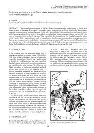
ALPINE PERMAFROST OCCURRENCE AT MT. TAISETSU, CENTRAL<br />
HOKKA 0, IN NORTHERN JAPAN<br />
1- Toshio, Takahashi, Nobuyuki and Fukuda, Masami<br />
Some<br />
183<br />
189<br />
194<br />
199<br />
205<br />
208<br />
213<br />
218<br />
224<br />
230<br />
233<br />
237<br />
241<br />
247<br />
253
ROCK GLACIERS AND GLACIATION OF THE CENTRAL ASIA MOUNTAINS<br />
S.N.Titkov<br />
GEOCRYOGENIC GEOMORPHOLOGY, EAST Flank OF THE ANDES OF<br />
MENDOZA, AT 330 S.L.<br />
D. Trombotto<br />
OUTER LIMIT OF PERMAFROST DURING THE LAST GLACIATION IN<br />
EAST CHINA<br />
Xu, Shuying, Xu, Defu and Pan, Baotian<br />
THE GEOCRYOLOGICAL MAP OF THE USSR OF 1:2,5OO,OOO SCALE<br />
ED. Yershov, KA. K<strong>on</strong>dratyeva, SA. Zamolotchikova, N.I. Trush and<br />
YeN. Dunaeva<br />
THE PERMAFROST ZONE EVOLUTION INDUCED BY DESTRUCTION OF<br />
Soil OVEWYING COVER IN THE AMUR NORTH<br />
S.I. Zubolotnik<br />
DISTRIBUTION OF SHALLOW PERMAFROST ON MARS<br />
A.P. Zent F.P. Fanale, JR. Salvail and S.E. Postawko<br />
259<br />
263<br />
268<br />
274<br />
278<br />
284<br />
PHYSICS AND CHEMISTRY OF FROZEN GROUND,<br />
FROST HEAVE MECHANISM<br />
ON THE METHOD OF CRYOHYDROGEOCHEMICAL INVESTIGATIONS<br />
N.P. Anisinwva<br />
Hydrochemistry OF RIVERS IN MOUNTAIN PERMAFROST AT 330 L.S.,<br />
MENDOZA - ARGENTINA<br />
EM. Buk<br />
FROST LINE BEHAVIOUR AROUND A COOLED CAVITY<br />
A.M. Cames-Pintaux and J. Aguirre-Puente<br />
A FROST HEAVE MODEL OF SANDY GRAVEL IN OPEN SYSTEM<br />
Chen, XB., Wang, KQ. and He, P,<br />
OBSERVATIONS OF MOISTURE MIGRATION IN FROZEN SOILS DURING<br />
THAWING<br />
Cheng, Guohng and E J. Chamberlain<br />
GEOCRYOLOGIC STUDIES AIMED AT NATURE CONSERVATION<br />
AB. Chizhov, A. Gavrilov and Ye.I. Pizhankova<br />
IRON AND CLAY MINERALS IN PERIGLACIAL ENVIRONMENT<br />
T. Chodak<br />
290<br />
294<br />
299<br />
304<br />
308<br />
316
FROZEN SOIL MACRO- AND MICROTEXTURE FORMATION<br />
YeM. Chuvilin and O.M. Yazynin<br />
ACOUSTICS AND UNFROZEN WATER CONTENT DETERMINATION<br />
M.H. Deschatres, F. Cohen-Tenoudji, J. Aguirre-Puente and B. Khastou<br />
THERMODYNAMICS THEORY FORECASTING FROZEN GROUND<br />
Ding, Dewen<br />
PORE SOLUTIONS OF FROZEN GROUND AND ITS PROPERTIES<br />
EJ. Dubikov, N.V. Ivarwva and VJ. Akrenov<br />
FORMATION PROBLEM OF THICK ICE STREAKS, ICE SATURATED<br />
HORIZONS IN PERMAFROST<br />
G.M. Feldman<br />
FROST HEAVE<br />
K.S. Forland T. Forland and S.K. Ratkje<br />
PARAMETRIC EFFECTS IN THE Filtrati<strong>on</strong> FREE CONVECTION MODEL<br />
FOR Patterned GROUND<br />
KJ. Gleas<strong>on</strong>, W. B. Kruntz and N. Caine<br />
HEAT AND MOISTURE TRANSPORT DURING ANNUAL FREEZING AND<br />
THAWING<br />
JP. Gosink, K. Kawasaki, T.E. Osterkamp and J. Holty<br />
SUMMER THAWING OF DIFFERENT GROUNDS - AN EMPIRICAL MODEL<br />
FOR WESTERN SPITSBERGEN<br />
M. Grzes<br />
OBSERVATIONS ON THE REDISTRIBUTION OF MOISTURE IN THE ACTIVE<br />
LAYER AND PERMAFROST<br />
S.A. Harris<br />
A MATHEMATICAL MODEL OF FROST HEAVE IN GRANULAR Materials<br />
D. Piper, J.T. Holden and R.H. J<strong>on</strong>es<br />
ELECTRIC CONDUCTIVITY OF AN ICE CORE OBTAINED FROM MASSIVE<br />
GROUND ICE<br />
Horiguchi, Kaoru<br />
PHYSICAL-CHEMICAL TYPES OF CRYOGENESIS<br />
VN. K<strong>on</strong>ischm V.V Rogov and SA. Pokl<strong>on</strong>ny<br />
TEMPERATURE OF ICE LENS FORMATION IN FREEZING SOILS ,<br />
J.M. K<strong>on</strong>rad<br />
Microstructure OF FROZEN SOILS EXAMINED BY SEM<br />
;‘Kumai,jMotov<br />
, ”. . ,,-./<<br />
CRYOGENIC DEFORMATIONS IN FINE-GRAINED SOILS<br />
Yu P. Lebedenko and L.V; Shevchenko<br />
320<br />
324<br />
329<br />
333<br />
339<br />
344<br />
349<br />
355<br />
361<br />
364<br />
370<br />
377<br />
381<br />
384<br />
390<br />
396
PROPERTIES OF GEOCHEMICAL FIELDS IN THE PERMAFROST ZONE<br />
V.. Makarov<br />
THE DYNAMICS OF SUMMER GROUND THAWING IN THE Kaffioyra<br />
PLAIN (NW SPITSBERGEN)<br />
K. Marcinid, R. Przybylak, W. Szczepanik<br />
A METHOD FOR MEASURING THE RATE OF WATER TRANSPORT DUE TO<br />
Temperature GRADIENTS IN UNSATURATED FROZEN SOILS<br />
Nakarw, Yoshisuke and AR. Tice<br />
FILTRATION PROPERTIES OF FROZEN GROUND<br />
BA. Olovin<br />
"HERMODIFFUSE ION TRANSFER IN GROUNDS<br />
YE. Ostroumov<br />
ELECTROACOUSTIC Effect IN FROZEN SOILS<br />
A.S. Pavlov and AD. Frolov<br />
SPATIAL VARIATION IN SEASONAL FROST HEAVE CYCLES<br />
E. Perfect R.D. Miller and B. Burt<strong>on</strong><br />
Directi<strong>on</strong> OF ION MIGRATION DURING COOLING AND FREEZING<br />
PROCESSES<br />
Qiu, Guoqing, Sheng, Wenkun, Huang, Cuilan and Zheng, Kaiwen<br />
DYNAMICS OF PERMAFROST Active LAYER - SPITSBERGEN<br />
J. Repelewska-Pekalowa and A. Gluza<br />
INVESTIGATION OF ELECTRIC POTENTIALS IN FREEZING DISPERSE<br />
SYSTEMS<br />
VP. Romanov<br />
PHYSICO-CHEMICAL NATURE OF CONGELATION STRENGTH<br />
B A. Saveliev, V.V. Razumov and VE. Gagarin<br />
HYDROGEOCHEMISTRY OF-KRYOLITHOZONE OF SIBERIAN PLATFORM<br />
SL. Schwartsev, VA. Zuev and MB. Bukaty<br />
THE FORMATION OF PEDOGENIC CARBONATES ON SVALBARD:<br />
THE INFLUENCE OF COLD TEMPERATURES AND FREEZING<br />
R .S. Sletten<br />
Measurement OF THE UNFROZEN WATER CONTENT OF SOILS:<br />
A COMPARISON OF NMR AND TDR METHODS<br />
M.W. Smith and AR. Tice<br />
GENESIS OF ARCTIC BROWN SOILS (PERGELIC CRYOCHREPT) IN<br />
SVALBARD<br />
F.C. Ugolini and R.S. Sletten<br />
401<br />
406<br />
412<br />
418<br />
425<br />
431<br />
436<br />
442<br />
448<br />
454<br />
459<br />
462<br />
467<br />
473<br />
478
OXYGEN ISOTOPIC COMPOSITION OF SOME MASSIVE GROUND ICE<br />
LAYERS IN THE NORTH OF WEST SIBERIA<br />
RA. Vaikmae VJ. Solomatin and Y.G. Karpov<br />
OXYGEN ISOTOPE VARIATIONS IN ICE-WEDGES AND MASSIVE ICE<br />
YuK. Vasilchuk and V.T. Trofimv<br />
THERMODYNAMIC AND MECHANICAL CONDITIONS WITHIN FROZEN<br />
Soils AND THEIR EFFECTS<br />
PJ. William<br />
TlME AND SPATIAL Variati<strong>on</strong> OF TEMPERATURE OF ACTIVE LAYER-<br />
IN SUMMER ON THE Kaffioyra PLAIN (NW SPITSBERGEN)<br />
G. Wojcik K. Marciniak and R. Prqbylak<br />
Temperature OF Active LAYER AT BUNGER OASIS IN ANTARCTICA<br />
IN SUMMER 1978-79<br />
G. Wdjcik<br />
CHEMICAL WEATHERING<br />
PERMAFROST REGIONS OF ANTARCTICA:<br />
GREAT WALL STATION OF CHINA, CASEY STATION AND DAVIS STATION<br />
OF AUSTRALIA<br />
Xie, Youyu<br />
WATER MIGRATION IN SATURATED Freezing Soil<br />
Xu, Xiaozu, Deng, Youseng, Wang, Jiacheng and Liu, Jiming<br />
EFFECT OF OVER CONSOLIDATION RATIO OF SATURATED SOIL ON<br />
FROST HEAVE AND THAW SUBSIDENCE<br />
Yamamcto, H., Ohrai, T. andIzuta, H.<br />
MASS TRANSFER INFROZEN SOILS<br />
ED. Yershov, YuP. Lebedenko, VD. Yershov and Ye.M. Chuvilin<br />
STRESS-STRAIN PREDICTION OF FROZEN Retaining STRUCTURES<br />
REGARDING THE FROZEN SOL CREW<br />
YuK. Zaretsb, Z.G. Ter-Martirosyan and A.G. Shchobolev<br />
STUDY OF FROZEN SOILS BY GEOPHYSICAL METHODS<br />
YuD. Zykov, N.Yu. Rozhdestuenrky and OP. Chervinskaya<br />
484<br />
489<br />
493<br />
499<br />
505<br />
511<br />
516<br />
522<br />
528<br />
533<br />
537
I<br />
HYDROLOGY, ECOLOGY OF NATURAL AND DISTURBED AREAS<br />
THE OUTFLOW OF WATER IN PERMAFROST ENVIRONMENT -<br />
SPITSBERGEN 543<br />
S. Bartoszewski, J. Rodzik and K. Wojciechowski<br />
MODELLING OF AVERAGE M<strong>on</strong>thly STREAMFLOWS FROM<br />
GLACIERIZED BASINS IN ALASKA 546<br />
D. Bjerkelie and R.F. Carls<strong>on</strong><br />
PROTECTION OF The ENVIRONMENT IN JAMESON LAND 552<br />
C. Baek-Madsen<br />
SUSPENDED SEDIMENT TRANSPORT IN ARCTIC RIVERS<br />
MJ. Clark, A.M. Gurnell and JL. Threlfall<br />
558<br />
THE BUFFERING POTENTIAL OF CARBONATE SOILS IN DISCONTINUOUS<br />
PERMAFROST TERRAIN, AGAINST NATURAL AND MAN-INDUCED<br />
ACIDIFICATION 564<br />
LA. Dredge<br />
PHYSICAL AND CHEMICAL CHARACTERISTICS OF THE Active LAYER<br />
AND NEAR-SURFACE PERMAFROST IN A DISTURBED HOMOGENEOUS<br />
PICEA MARIANA STAND, FORT NORMAN, N.W.T., CANADA 568<br />
K.E. Evans, G.P. Kershaw and B J. Gallinger<br />
HYDROLOGY AND GEOCHEMISTRY OF A SMALL DRAINAGE BASIN IN<br />
UPLAND TUNDRA, NORTHERN ALASKA 574<br />
KR. Everett and B. Ostendorf<br />
ENVIRONMENT Protecti<strong>on</strong> Studies IN PERMAFROST ZONE OF<br />
THE USSR 580<br />
NA. Grave<br />
CLASSIFICATION OF GROUND WATER IN PERMAFROST AREAS ON THE<br />
QINGHAI-XTZANG PLATEAU, CHINA 583<br />
Guo, Pengfei<br />
<strong>Permafrost</strong> HYDROLOGY OF A SMALL ARCTIC WATERSHED 590<br />
DL. Kane and L.D. Hinzman<br />
FLOWING WATER EFFECT ON TEMPERATURE IN OUTWASH DEPOSITS 596<br />
A. Karczewski<br />
SALIX ARBUSCLEOIDES ANDERSS, RESPONSE TO DENUDING AND<br />
IMPLICATIONS FOR NORTHERN RIGHTS-OF-WAY 599<br />
G.P. Kershaw, B J. Gallinger and L J. Kershaw<br />
ABLATION OF MASSIVE GROUND ICE, MACKENZIE DELTA 605<br />
A.G. Lmkowicz<br />
HYDROGEOLQGICAL FEATURES IN HUOLAHE BASIN OF NORTH<br />
DAXINGANLING, NORTHEAST<br />
Lira, Fengt<strong>on</strong> and Tu, Guangzh<strong>on</strong>g<br />
CHINA 611
SHALLOW OCCURRENCE OF WEDGE ICE: IRRIGATION FEATURES<br />
A A. Mandamv and IS. Ugarov<br />
SOIL INFILTRATION AND SNOW-MELT RUN-OFF IN THE MACKENZIE<br />
DELTA, N.W.T.<br />
P. Marsh<br />
LATE PLEISTOCENE DISCHARGE OF THE YUKON RIVER<br />
OK. Mas<strong>on</strong> and J.E. Beget<br />
INFLUENCE OF WATER PHENOMENA ON Depth OF SOIL THAWING IN<br />
OSCAR 11 LAND, NORTHWESTERN Spitsbergen<br />
C. Pietrucien and R. Skowr<strong>on</strong><br />
INFLUENCE OF AN ORGANIC MAT ON THE ACTIVE LAYER<br />
D.W. Riseborough and CR. Burn<br />
PERENNIAL DISCHARGE OF SUBPERMAFROST GROUNDWATER IN TWO<br />
SMALL DRAINAGE BASINS, YUKON, CANADA<br />
R.O. Van Everdingen<br />
WETLAND RUNOFF REGIME IN NORTHERN CANADA<br />
Woo, M.K.<br />
STREAMFLOW CHARACTERISTICS OF THE QINGHAI<br />
(NORTHERN TIBETAN) PLATEAU<br />
Yang, Zhengniang and Woo, Ming-hm<br />
RATIONAL EXPLOlTATION AND UTILIZATION OF GROUND WATER IN<br />
PERMAFROST REGION OF THE MT.DA-XINGANLING AND MT.XIAO-<br />
XINGANLING, NORTHEAST CHINA<br />
Zheng, Qipu<br />
615<br />
618<br />
622<br />
628<br />
633<br />
639<br />
644<br />
650<br />
656<br />
PERIGLACIAL PHENOMENA, GEOCRYOLOGY<br />
GROUNDWATER PROTECTION IN THE PERMAFROST ZONE<br />
V.Ye. Afanusenko and V.P. Volkova<br />
MINERO-CRYOGENIC PROCESSES<br />
A. L. Ahumada<br />
UPFREEZING IN SORTED CIRCLES, WESTERN SPITSBERGEN<br />
S. Prestrud Anders<strong>on</strong><br />
TEPHRAS AND SEDIMENTOLOGY OF FROZEN ALASKAN LOESS<br />
J.E. Beget<br />
MORPHOLOGICAL FEATURES OF THE ACTIVE ROCK GLACIERS IN THE<br />
ITALIAN ALPS AND CLIMATIC CORFSLATIONS<br />
S. Bell<strong>on</strong>i, M. Pemni and C. Smiraglia<br />
659<br />
661<br />
666<br />
672<br />
678
OBSERVATIONS ON NEAR-SURFACE CREEP IN PERMAFROST, EASTERN<br />
Melville ISLAND, ARCTIC CANADA 683<br />
L.P. Bennett and HM. French<br />
OBSERVATIONS ON AN ACTIVE LOBATE ROCK GLACIER, SLIMS RIVER<br />
VALLEY, ST, ELIAS RANGE, CANADA<br />
W. Blumstengel & SA. Harris<br />
GENERAL MOISTENING OF THE AREA AND INTENSITY OF CRYOGENIC<br />
PROCESSES<br />
NF. Bosibv<br />
THERMOKARST LAKES AT MAYO, YUKON TERRITORY, CANADA<br />
CR. Burn and M.W. Smith<br />
LOESS AND DEEP THERMOKARST BASINS IN ARCTIC ALASKA<br />
L.D. Carter<br />
A FIRST APPROACH TO THE SYSTEMATIC STUDY OF THE ROCK<br />
GLACIERS IN THE ITALIAN ALPS<br />
A. Cart<strong>on</strong>, F. Dramis, and C. Smiraglia<br />
GEOCRYOLOGY OF The CENTRAL ANDES AND ROCK GLACIERS<br />
A.E. Corte<br />
689<br />
695<br />
700<br />
706<br />
712<br />
718<br />
ROCK GLACIERS IN THE SOURCE REGION OF URUMQI RIVER, MIDDLE<br />
TIAN SHAN, CHINA<br />
Cui, Zhijiu and Zhu, Cheng<br />
SEASONAL FROST MOUNDS IN AN EOLIAN SAND SHEET NEAR S<strong>on</strong>dre<br />
Stromfjord W. GREENLAND<br />
J.W.A. Dijhns<br />
PINGOS IN ALASKA: A REVIEW 734<br />
0 J. Ferrians, Jr.<br />
REGULARITIES IN FORMING THE DISCONTINUITY OF A CRYOGENIC<br />
SERIES 740<br />
S.M. Fotiev<br />
ROCK GLACIER RHEOLOGY A PRELIMINARY ASSESSMENT 744<br />
JR. GiamIino and JD. Vitek<br />
THE USE OF MICROBIOLOGICAL CHARACTERISTICS OF ROCKS IN<br />
GEOCRYOLOGY 749<br />
D A. Gilichinsky, G M. Khlebnibva, D.C. Zvyagintsev,<br />
D.C. Fetiorov-Davydov and NN. Kudryavtseva<br />
THERMIC OF PERMAFROST ACTIVE LAYER - SPITSBERGEN 754<br />
A. Gluza, J. Repelewska-Pekalowa and K. Dabrowski<br />
724<br />
728
SOIL FORMATION PALEOGEOGRAPHIC ASPECTS IN YAKUTIYA<br />
S.V. Gubin<br />
AEROPHOTOGRAMMETRICAL MONlTORING OF ROCK GLACIERS<br />
W. Haeberli and W. Schmid<br />
SURFACE SOIL DISPLACEMENTS IN SORTED CIRCLES, WESTERN<br />
SPITSBERGEN<br />
B. Hallet, S. Prestrud Anders<strong>on</strong>, C.W. Stubbs and E. Carringt<strong>on</strong> Gregory<br />
MICROMORPHOLOGY AND MICROFABRICS OF SORTED CIRCLES,<br />
JOTUNHEIMEN, SOUTHERN NORWAY<br />
C. Harris and JD. Cook<br />
CRYOSTRATIGRAPHTC STUDIES OF PERMAFROST, NORTHWESTERN<br />
CANADA<br />
D.E. Harry and H.M. French<br />
THAW LAKE SEDIMENTS AND SEDIMENTARY ENVIRONMENTS<br />
D.M. Hopkins and J.G. Kidd<br />
PERIGLACIAL SOIL Structures IN SPITSBERGEN AND IN CENTRAL<br />
EUROPA<br />
A. Jahn<br />
CONTINUOUS PERSISTENCE OF THE PERMAFROST ZONE DURING THE<br />
QUATERNARY PERIOD<br />
EM. Katas<strong>on</strong>ov<br />
PROBLEM OF INTEGRAL INDEX STABILlTY OF Ground COMPLEX OF<br />
PERMAFROST<br />
VP. Kovalbv and P.F. Shvetsov<br />
ICE WEDGE GROWTH IN NEWLY AGGRADING PERMAFROST, WESTERN<br />
Arctic COAST, CANADA<br />
J. Ross Mackay<br />
HEAT FLOW AND PECULIARlTIES OF CRYOLlTHOZONE IN WESTERN<br />
SIBERIA<br />
VP. Melnikov, VN. Devyatkin and Y.P. Bevzenko<br />
MICROTOPOGRAPHIC THERMAL CONTRASTS, NORTHERN ALASKA<br />
F.E. Nels<strong>on</strong>, SJ. Outcalt, KM, Hinkel, D.F. Murray and B.M. Murray<br />
FROST MOUNDS IN Kaffioyra AND HERMANSENOYA,<br />
NW SPITSBERGEN, AND THEIR ORIGIN<br />
W. Niewiarowski and M. Sinkiewicz<br />
CONTEMPORARY FROSTACITONONDIFFERENTORIENTEDROCKWALLS:<br />
AN EXAMPLE FROM THE SWISS JURA MOUNTAINS<br />
A. Pancza and J.-Cl. Ozouf<br />
759<br />
764<br />
770<br />
776<br />
784<br />
790<br />
796<br />
801<br />
805<br />
809<br />
815<br />
819<br />
824<br />
830
,<br />
, I<br />
GEOCRYOGENIC Slope Caves in The SOUTHERN CASCADES<br />
FL. Perez<br />
TRACES OF ICE IN CAVES: Evidence of FORMER PERMAFROST<br />
A. Pissart, B. Van Vliet-Lame, C. Ek and E. Juvigne<br />
THE THEORY OF CRYOLITHOGENESfS<br />
AJ. Popov<br />
ORIGIN OF MASSIVE GROUND ICE ON TUKTOYAKTUR PENINSULA,<br />
NORTHWEST Territories CANADA: A REVIEW OF Stratigraphic<br />
AND GEOMORPHIC EVIDENCE 850<br />
VA. Rampt<strong>on</strong><br />
ANDES SLOPE Asymmetry DUE TO Geliflucti<strong>on</strong><br />
M.C. Regairaz<br />
THE DEVELOPMENT OF DEPRESSED-CENTRE ICE-WEDGE POLYGONS IN<br />
THE Northernmost UNGAVA PENINSULA, QUEBEC, CANADA 862<br />
M. Seppala, J. Gray and J. Richard<br />
The UPPER HORIZON OF PERMAFROST SOILS 867<br />
Yu L. Shur<br />
FROST SHATTERING OF ROCKS IN The LIGHT OF POROSITY 872<br />
R. Uwinoka and P. Nieminen<br />
FLUVIO-AEOLIAN INTERACTION In A REGION OF CONTINUOUS<br />
* ,<br />
PERMAFROST<br />
J. Vandenberghe and J. Van Huissteden<br />
Regularities OF FORMING SEASONALLY CRYOGENIC GROUND 882<br />
EA. Vtyurina<br />
Observati<strong>on</strong>s OF SORTED.CIRCLE Activity CENTRAL ALASKA 886<br />
J.C. Walters<br />
Patterned GROUND GEOLOGIC CONTROLS, MENDOZA, ARGENTINA 892<br />
WJ. Wayne I(<br />
LANDSLIDE MOTION IN DISCONTINUOUS PERMAFROST 897<br />
S.C. Wilbur and J.E. Beget<br />
THE CHARACIERISTIC OF CRYOPLANATION LANDFORM IN THE<br />
Interior OF area QINGHAI-XIZANQ PLATEAU , < 903<br />
Zhang, Weixin, Shi, Shengmn, Chen, Fahu and Xu, Shuying<br />
THE PREDICTION OF PERMAFROST ENERGY STABILITY 906<br />
LA. Zhigarew and 0.Yu. Parmuzina<br />
834<br />
840<br />
846 '<br />
856<br />
876
VOLUME 2: ENGINEERING<br />
SITE INVESTIGATIONS AND Terrain ANALYSES,<br />
SUBSEA PERMAFROST<br />
BOREHOLE INVESTIGATIONS OF THE Electrical PROPERTIES OF<br />
FROZEN SILT<br />
SA. Arc<strong>on</strong>e and A J. Delaney<br />
PERMAFROST AND Terrain Preliminary MONITORING RESULTS,<br />
NORMAN WELLS PIPELINE CANADA<br />
M.M. Burgess<br />
CONTRIBUTION TO THE STUDY OF THE Active LAYER IN THE AREA<br />
AROUND CENTRUM LAKE, NORTH EAST GREENLAND<br />
M. Chir<strong>on</strong> and J.-F. Loubiere<br />
SEASONAL VARIATIONS IN RESISTIVITY AND TEMPERATURE IN<br />
Disc<strong>on</strong>tinuous PERMAFROST<br />
A. Delaney, P. Sellmann and S. Arc<strong>on</strong>e<br />
PERMAFROST CONDITIONS IN THE SHORE AREA AT SVALBARD<br />
0. Gregersen and T. Eidsmoen<br />
CORE DRILLING THROUGH ROCK GLACIER-PERMAFROST<br />
W. Haeberli, J. Huder, H.-R. Keusen, J. Pika and H. Rdthlisberger<br />
REMOTE Sensing LINEAMENT STUDY IN NORTHWESTERN ALASKA<br />
Huang, SL, and N. Lozano<br />
THERMAL EVIDENCE FOR AN ACTIVE LAYER ON THE Seabottom OF<br />
THE CANADIAN BEAUFORT SEA SHELF<br />
J A. Hunter HA. MacAulay, S.E. Pullan. R.M. Gagne RA. Burns and RL. Good<br />
FOUNDATION CONSIDERATIONS FOR Siting AND DESIGNING THE RED<br />
DOG MINE MILL FACILlTES ON PERMAFROST<br />
T.G. Krzavinski, T.A. Hammer and G.G. Booth<br />
ELECTRIC PROSPECting OF INHOMOGENEOUS FROZEN MEDIA<br />
V;V: Kuskov<br />
PREDICI'ION OF PERMAFROST THICKNESS BY THE 'TWO POINT" METHOD<br />
I.M. Kutasov<br />
THE USE OF GROUND PROBING RADAR IN THE DESIGN AND MONITORING<br />
OF WATER RETAINING EMBANKMENTS INPERMAFROST 971<br />
P.T. Lafleche A.S. Judge and JA. Pil<strong>on</strong><br />
PEAT FORMATION IN SVALBARD<br />
J. Lag<br />
910<br />
916<br />
922<br />
927<br />
933<br />
937<br />
943<br />
949<br />
955<br />
961<br />
965<br />
977
PERMAFROST GEOPHYSICAL INVESTIGATION AT THE NEW AIRPORT<br />
SITE OF KANGIQSUALUJJUAQ, Northern QUEBEC, CANADA 980<br />
M.K. Seguin, E. Gahe M. Allardand K. Ben-Mibud<br />
D.C. RESISTIVITY ALONG THE COAST AT PRUDHOE BAY, ALASKA 988<br />
P.V. Sellmann, A J. Delaney and SA. Arc<strong>on</strong>e<br />
EM SOUNDINGS FOR MAPPING COMPLEX GEOLOGY IN THE<br />
PERMAFROST TERRAIN OF NORTHERN CANADA<br />
AX. Sinhu<br />
MAPPING AND ENGINEERING-GEOLQGIC EVALUATION OF KURUMS 1000<br />
AJ. Tyurin, NN. Romanovsky and D.O. Sergqev<br />
Development AND THAWING OF ICE~RICH PERMAFROST AROUND<br />
CHILLED PIPELINES MONITORED BY RESISTANCE GAUGES 1004<br />
R.O. Van Everdingen and L.E. Carls<strong>on</strong><br />
THE ORIGIN OF PATTERNED GROUNDS IN N.W. SVALBARD 1008<br />
B. Van Vliet-Lanoe<br />
THE STATISTICAL ANALYSIS ON FROST HEAVE OF SOILS IN<br />
SEASONALLY GROUND FROZEN AREA 1014<br />
Wang, Jianguo and Xie, Yinqi<br />
DISCONTINUOUS PERMAFROST MAPPING USING THE EM-31<br />
D.S. Washburn and A. Phukan<br />
994<br />
1018<br />
A DISCUSSION ON MAXIMUM SEASONAL FROST DEPTH OF GROUND 1024<br />
Xu, Ruiqi, Pang, Guoliang and Wang, Bingcheng<br />
PRINCIPLES FOR COMPILING AN ATLAS OF SEASONAL FROST<br />
Penetrati<strong>on</strong> JILIN, CHINA (1: 2000000) 1026<br />
Zhang, Xing, Li, yinr<strong>on</strong>g and S<strong>on</strong>g, Zhengyuan<br />
GEOTECHNICAL Properties FROST HEAVE PARAMETERS<br />
SEGREGATION FREEZING OBSERVED IN WELDED TUFF BY OPEN<br />
SYSTEM FROST TEST HEAVE<br />
1030<br />
Akagawa,Satoshi, Goto, Shigem and Saito,Akira<br />
SOME ASPECTS OF SOILS ENGINEERING PROPERTIES IMPROVEMENT<br />
DURING DAM CONSTRUCTION 1036<br />
G.F. Bianov, V.. Makarov and EL. Kadkinu<br />
FROST HEAVE FORCES ON H AND PIPE FOUNDATION PILES 1039<br />
J.S. Buska and J.B. Johns<strong>on</strong>
THAW Settlement OF FROZEN SUBSOILS IN SEASONAL FROST<br />
REGIONS<br />
Cheng, Enyuan and Jiang, H<strong>on</strong>giu<br />
TENSILE ADFREEZING STRENGTH BETWEEN SOIL AND FOUNDATION<br />
Ding, Jingkang, Lou, Anjin and Yang, Xueqin<br />
Interacti<strong>on</strong> BETWEEN A Laterally LOADED PILE AND FROZEN SOIL<br />
L. Domaschuk, L. Franss<strong>on</strong> and DH. Shields<br />
CHOICE OF Parameters OF IMPACT BREAKAGE OF FROZEN SOILS<br />
AND ROCKS<br />
AJ. Fedulov and V... Labustin<br />
FROST HEAVE CHARACTERISTICS OF SALINE SOILS AND CANAL<br />
DAMAGE<br />
Feng, Ting<br />
MECHANICAL PROPERTIES OF FROZEN SALINE CLAYS<br />
T. Furuberg and A.-L. Berggren<br />
DECREASED SHEAR STRENGTH OF A Silty SAND Subjected TO FROST<br />
G.P. GiSford<br />
THEORETICAL Froblems OF CRYOGENIC GEOSYSTEM Modelling<br />
S.E. Grechishchev<br />
USE OF GEOTEXTILES TO MITIGATE FROST HEAVE IN SOILS<br />
K. Henry<br />
VOLUME OF FROZEN GROUND STRENGTH TESTING<br />
LN. Khrustalev and G.P. Pustovoit<br />
MECHANICAL FROZEN ROCK-FILL PROPERTIES AS SOIL STRUCTURE<br />
YaA. Kr<strong>on</strong>ik, AN. Gavrilov and VN. Shramkova<br />
A STUDY OF FROST HEAW IN LARGE U-SHAPED<br />
Li, Anguo<br />
CONCRETE CANALS<br />
FROST HEAVING FORCE ON THE FOUNDATION OF A HEATING BUILDING<br />
Liu, H<strong>on</strong>gxu<br />
FROST HEAVE IN SALINE-SATU'RATED FINE-GRAINED SOILS<br />
B.T.D. Lu, ML. Le<strong>on</strong>ard and L. Mahar<br />
EFFECT OF Variable THERMAL PROPERTIES ON FREEZING WITH AN<br />
UNFROZEN WATER CONTENT<br />
VJ. Lunardini<br />
DEVELOPMENT AND APPLICATION PRACTICE OF METHODS FOR<br />
PRELIMINARY THAWING OF PERMAFROST SOILS IN FOUNDATIONS<br />
E.S. Maksimenko<br />
1051<br />
1056<br />
1060<br />
1066<br />
1071<br />
1078<br />
1085<br />
1091<br />
1096<br />
1102<br />
1106<br />
1110<br />
1116<br />
1121<br />
1127<br />
1133
SECONDARY CREEP INTERPRETATIONS OF ICE RICH PERMAFROST<br />
E.C. McRoberts<br />
PHASE RELAXATION OF THE WATER IN FROZEN GROUND SAMPLES<br />
V.P. Melnikov, L.S. Podenko and A.G. Zavodovski<br />
STANDARD METHOD FOR PILE LOAD TESTS IN PERMAFROST<br />
R J. Neukirchner<br />
CRYOGENIC HEAVE UNDER FREEZING OF ROCKS<br />
VL. Nevecherya<br />
EFFECTIVE LIFE IN CREEP OF FROZEN SOILS<br />
KR . Parameswaran<br />
HORIZONTAL FROST HEAVE FORCE ACTING ON THE RETAINING<br />
WALL IN SEASONAL Frozen REGIONS<br />
Shui, Tieling and Na, Wenjie<br />
DYNAMIC LOAD EFFECT ON Settlement OF MODEL PILES IN<br />
FROZEN SAND<br />
D.L. Stelzer and OB. Andersland<br />
TANGENTIAL FROST-HEAVING FORCE OF THE REINFORCED CONCRETE<br />
PILE AND CALCULATION OF PREVENTING IT FROM PULLING UP DUE<br />
TO FROST HEAVE<br />
Sun, Yuiiang<br />
BEHAVIOUR OF LONG PILES IN PERMAFROST<br />
A. Theriault and B. Ludanyi<br />
INVESTIGATION ON TANGENTIAL FROST HEAVING FORCES<br />
T<strong>on</strong>g, Changiiang, Yu, Ch<strong>on</strong>gyun and Sun, Weimin<br />
STRESS-STRAIN BEHAVIOUR OF FROZEN SOILS<br />
S.S. Vyalov R.V. Maximyak, VN. Razbegin, M.E. Slepak and A.A. Chapayev<br />
FROST HEAVING FORCES ON FOUNDATIONS IN SEASONALLY<br />
FROZEN GROUND<br />
Xu, Shaoxin<br />
ON THE DISTRIBUTION OF FROST HEAVE WITH DEPTH<br />
Zhu, Qiang<br />
TRIAXIAL COMPRESSIVE STRENGTH OF FROZEN SOILS UNDER<br />
CONSTANT STRAIN RATES<br />
Zhu, Yuanlin and D.L. Carbee
\<br />
Geotechnical ENGINEERING, PIPELINE CONSTRUCTION<br />
LONG TERM Settlement TEST (3 YEARS) FOR CONCRETE PILES IN<br />
PERMAFROST<br />
B A. Bredesen, 0. Puschmann and 0. Gregersen<br />
TANGENTIAL FROST HEAVING FORCE ON REINFORCED CONCRETE<br />
PILES OFHIGHWAY BRIDGE<br />
Dai, Huimin and Tian, Deting<br />
PERFORMANCE OF TWO EARTHFILL DAMS AT LUPIN, N.W.T<br />
S. Dufour and I. Holubec<br />
ROADWAY EMBANKMENTS ON WARM <strong>Permafrost</strong> PROBLEMS AND<br />
REMEDIALTREATMENTS<br />
D. Esch<br />
REMEDIAL SOLUTIONS FOR Pipeline THAW SETTLEMENT<br />
J.E. Ferrell and H. P. Thomas<br />
A FROZEN FOUNDATION ABOVE A TECHNOGENIC TALK<br />
I.E. Guryanov<br />
ASSESSMENT OF KEY DESIGN ASPECTS OF A 150 FOOT HIGH EARTH<br />
DAM ON WARM PERMAFROST<br />
TA. Humme< T.G. Krzewinski and G.G. Booth<br />
PERMAFROST SLOPE DESIGN FOR A BURIED OIL PIPELINE<br />
A J. Hanna and E.C. McRoberts<br />
A METHOD FOR Calculating THE Minimum BURIED DEPTH OF<br />
BUILDING FOUNDATIONS<br />
Jiang, H<strong>on</strong>gju and Cheng, Enyuan<br />
PROTECTION OF WARM PERMAFROST USING CONTROLLED<br />
SUBSIDENCE AT NUNAPITCHUK Airport<br />
E.G. Johns<strong>on</strong> and G.P. Bradley<br />
THERMAL PERFORMANCE OF A SHALLOW UTILIDOR<br />
F.E. Kennedy, G. Phetteplace, N. Humist<strong>on</strong> and V. Prabhakar<br />
CONSTRUCTION OF HYDROS IN COLD CLIMATE: ACHIEVEMENTS AND<br />
PROBLEMS<br />
Ld. Kudoyarov and NF. Kriv<strong>on</strong>ogova<br />
1206<br />
1212<br />
1217<br />
1223<br />
1229<br />
1235<br />
1242<br />
1247<br />
1253<br />
1256<br />
1262<br />
1268<br />
STUDY OF SOME GEOTECHNICAL ASPECTS EFFECTING CONSTRUCTION<br />
IN GLACIAL REGIONS OF HIMALAYAS 127 1<br />
D.S. Laljii and R.C. Pathak<br />
A SUBGRADE COOLING AND ENERGY RECOVERY SYSTEM<br />
EL. L<strong>on</strong>g and E. Yarmak Jr.<br />
1277
LONG TERM PLATE LOAD TESTS ON MARINE CLAY IN SVEA. ~Z SVALBARD -<br />
1282<br />
T. Lunne and T. Eidsmoen<br />
MELIORATION OF SOILS OF CRYOLITHOZONE<br />
0.K Makeev<br />
EMBANKMENT FAILURE FROM CREEP OF PERMAFROST FOUNDATION<br />
SOIL<br />
R. McHattie and D. Esch<br />
1288<br />
1292<br />
CONSTRUCTION OF EARTH Structures IN PERMAFROST AREAS BY<br />
HYDRAULIC METHODS<br />
P.I. Melnikov, Chang, R.V. G.P. Kuzmin and A.V. Yakovlev<br />
STORAGE TANK FOUNDATION DESIGN, PRUDHOE BAY, ALASKA, U.S.A.<br />
B. Nidowicz, D. Bruggers and V. Manikian<br />
STUDIES OF PIPELINE INTERACTION WITH HEAVING SOILS<br />
S.Yu. Pamtuzin, AD. Perelimiter and I.Ye. Naidenok<br />
YUKON RIVER BANK STABILIZATION: A CASE STUDY<br />
CH. Riddle, J.W. Ro<strong>on</strong>ey and S.R. Bredthauer<br />
AIRPORT RUNWAY DEFORMATION AT NOME, ALASKA<br />
J.W. Ro<strong>on</strong>ey, J.F. Nix<strong>on</strong>, C.H. Riddle and E.G. Johns<strong>on</strong><br />
PHYSICAL MODEL STUDY OF ARCTIC PIPELINE SETTLEMENT<br />
T.S. Vins<strong>on</strong> and A.C. Palmer<br />
BETHEL AIRPORT, CTB PAVEMENT PERFORMANCE ANALYSIS<br />
CL. vita, J.W. Ro<strong>on</strong>ey and T.S. Vins<strong>on</strong><br />
A NEW METHOD FOR PILE TESTING AND DESIGN IN<br />
PERMANENTLY-FROZEN GROUNDS<br />
S.S. Vyalov and Yu.S. Mirenburg<br />
CLASSIFICATION OF FROZEN HEAVE OF GROUND FOR HYDRAULIC<br />
ENGINEERING IN SEASONAL FROZEN REGIONS<br />
Xie, Yinqi, Wung, Jianguo and Han, Weijun<br />
RETAINING WALL WITH ANCHOR SLABS USING IN COLD REGION<br />
Xu, Bomeng and Li, Changlin<br />
THAW STABILIZATION OF ROADWAY EMBANKMENTS<br />
J.P. Zarling, W.A. Braley and D.C. Esch<br />
METHOD FOR CALCULATING FROST HEAVE REACTION FORCE IN<br />
SEASONAL FROST REGION<br />
Zhou, Youcai<br />
1298<br />
1301<br />
1307<br />
1312<br />
1318<br />
1324<br />
1330<br />
1336<br />
1341<br />
1346<br />
1352<br />
1358
ENGINEERING, -PETROLEUM, -MINING, -MUNICIPAL<br />
COLD-MIX ASPHALT CURING AT LOW Termperatures<br />
ANS. Beaty and P.M. Jarrett<br />
PROGNOSIS OF SOIL TEMPERATURE AT THE AREA UNDER<br />
CONSTRUCTION<br />
AL. Chekhovskyi<br />
PRESSURE IN RELATION TO FREEZING OF WATER-CONTAINING<br />
MASSES IN A CONFINED SPACE<br />
M.M. Dubina<br />
ENVIRONMENT PROTECTION FOR MINING ENTERPRISES IN<br />
PERMAFROST REGIONS<br />
EA. Elchaninov<br />
ARCTIC MINING IN PERMAFROST<br />
H.M. Giegerich<br />
APPLIED STUDY OF PREVENTING STRUCTURES FROM FROST DAMAGE<br />
BY USING DYNAMIC CONSOLIDATION<br />
Han, Huaguang and Euo, Mingzhu<br />
EFFECT OF HEATING ON FROST DEPTH BENEATH FOUNDATIONS OF<br />
BUILDING<br />
H<strong>on</strong>g, Yuping and Jiang, H<strong>on</strong>gju<br />
PREDICTION OF PERMAFROST THAWING AROUND MINE WORKINGS<br />
VYu. Izaks<strong>on</strong>, E.E. Petrov and A.V. Samokhin<br />
EXPERIENCE IN CONSTRUCTION BY STABILIZATION METHOD<br />
LN. Khrustalm and V.V. Nikiforov<br />
GEOCRYOLOGICAL STUDIES FOR RAILWAY CONSTRUCTION<br />
(STATE, Primary TASKS)<br />
V.G. K<strong>on</strong>dratyev AA. Korolyev, MI. Karlinski, EM. Timopheev<br />
and PN. Lugovoy<br />
VENTILATED SURFACE FOUNDATIONS ON PERMAFROST SOILS<br />
NB. Kutvitskqa and MR. Gokhman<br />
Results OF RESEARCHES AND EXPERIENCE OF HYDRAULIC MINING<br />
OF FROZEN ROCKS<br />
N.P. Lavrov, G.Z. Perlshtein and V.K. Samyshin<br />
OFFSHORE SEAWATER TREATING PLANT FOR WATERFLOOD PROJECT,<br />
PRUDHOE BAY OIL FIELD, ALASKA, U.S.A.<br />
V. Manikian and J.L. Machemehl<br />
1363<br />
1368<br />
1372<br />
1377<br />
1382<br />
1388<br />
1393<br />
1397<br />
1403<br />
1407<br />
1413<br />
1417<br />
1422
DEVELOPING A THAWING MODEL FOR SLUDGE FREEZING BEDS<br />
C. J. Martel<br />
ROCK MECHANICS RELATED TO COAL MINING IN PERMAFROST ON<br />
SPITZBERGEN<br />
A.M. Myrvang<br />
SETTLEMENTS OF THE FOUNDATIONS ON SEASONALLY Freezing<br />
SOILS<br />
V.O. Orlov and V.V. Fwsov<br />
REGULARITIES OF THERMAL AND MECHANICAL INTERACTION<br />
BETWEEN Culverts AND EMBANKMENTS<br />
NA. Peretrukhin and AA. Topekha<br />
Methods OF QUANTITATIVE VALUATION OF REGIONAL HEAT<br />
RESOURCES FOR PREPARATION OF PERMAFROST PLACER Deposits<br />
TO MINING<br />
G.Z. Perlshtein and V.E. Kapranov<br />
Stability OF ROAD SUBGRADES IN THE NORTH OF WEST SIBERIA<br />
A.G. Polmvsky and Yu.M. Lyvovitch<br />
REFLECTION SEISMIC EXPLORATION AND DATA PROCESSING IN COLD<br />
REGIONS<br />
F. Parturas<br />
PROBLEMS OF ARCTIC ROAD CONSTRUCTION AND MAINTENANCE IN<br />
FINLAND<br />
S. Saarelainen and J. Vaskelainen<br />
SOME ASPECTS OF FREEZING THE ICE PLATFORMS<br />
BA. Suveliev and DA. Latalin<br />
SLOPE STABILlTY IN ARCTIC COAL MINES<br />
AX. Sinha, M. Sengupta and T.C. Kinney<br />
THE RESISTANCE TO FROST HEAVE OF VARIOUS CONCRETE CANAL<br />
LINING<br />
S<strong>on</strong>g, Baoqing, Fan, Xiuting and Sun, Kehan<br />
THE BARROW DIRECT BURY Utilities SYSTEM DESIGN<br />
J.E. Thomas, P.E.<br />
COLD CRACKING OF Asphalt PAVEMENT ON HIGHWAY<br />
Tian, Deting and Dai, Huimin<br />
AIRPORT Network AND HOUSING CONSTRUCTION PROGRAMMES<br />
IN NORTHERN QUEBEC, CANADA<br />
C. Tremblay and G. Dork
FROST DAMAGE OF ENCLOSURE AND ITS MEASURE FOR PREVENTING<br />
FROST HAZARD<br />
Wang, G<strong>on</strong>gshan<br />
APPLICATION OF LIME STABILIZATION ON HIGHWAY PERMAFROST<br />
REGION, QINGHAI-XIZANG PLATEAU<br />
Wang, Qing-tu,Wu, Jing-min and Liu, Jian-du<br />
INVESTIGATION AND TREATMENT FOR SLOPE-SLIDING OF RAILWAY<br />
CUTTING IN PERMAFROST AREA<br />
Wang, Wenbao<br />
MODEL TEST TO DETERMINE Thawing DEPTH OF EMBANKMENT IN<br />
PERMAFROST REGION<br />
Ye, Bayou, T<strong>on</strong>g, Zhiquan, Lou Anjin and Shang, Jih<strong>on</strong>g<br />
STUDIES ON THE PLASTIC-FILM-ENCLOSED FOUNDATION OF SLUICE<br />
GATES AND ITS APPLICATION<br />
Yu, Bofang, Qu, Xiangmin and Jin, Naicui<br />
GEOCRYOLOGICAL BLOCK OF OIL AND GAS PRODUCING AND<br />
TRANSPORTING GEOTECHNICAL SYSTEMS<br />
YF. Zakharov, Y.Y. Podborny and GJ. PUSH<br />
1507<br />
1511<br />
1515<br />
1520<br />
1526<br />
1531
BOREHOLE INVESTIGATIONS OF THE ELECTRICAL<br />
PROPERTIES OF FROZEN SILT<br />
S.A. Arc<strong>on</strong>e and AJ. Delaney<br />
U.S. Army Cold Regi<strong>on</strong>s <strong>Research</strong> and Engineering Laboratory<br />
SYNOPS IS<br />
The dielectric c<strong>on</strong>stant and attenuati<strong>on</strong> rate of short radiowave pulses in frozen<br />
Fairbanks silt have been measured between boreholes.12 m deep and spaced between 4.4 and 17.6<br />
m. The ranges for volumetric ice c<strong>on</strong>tent and temperature were 44 to 79% and -6.0 (surface, early<br />
April) to -0.7-C (bottom) respectively. The pulses lasted approximately 30 ns, had a power spectrum<br />
centered near 100 MHz, and were transmitted and received at the same depth. Dielectric<br />
c<strong>on</strong>stants were determined from the propagati<strong>on</strong> time delay of the leading edge and there was no<br />
significant dispersi<strong>on</strong>. Attenuati<strong>on</strong> rates (dB/m) were determined by comparing signal levels<br />
received between different borehole pairs and were adjusted €or geometric spreading losses. C<strong>on</strong>current<br />
borehole dc resistivity measurements allowed estimates of the separate c<strong>on</strong>tributi<strong>on</strong>s of<br />
various loss mechanisms. The results show the dielectric c<strong>on</strong>stant to vary between 4.3 and 7.0<br />
and to correlate well with the volumetric ice c<strong>on</strong>tent, but not with temperature Average attenuati<strong>on</strong><br />
rates at any particular depth varied between 1.4 and 4.0 dB/m. The lowest values occurred<br />
in the secti<strong>on</strong>s with the higher ice c<strong>on</strong>tent. No more than 0.8 dB/m could be ascribed to c<strong>on</strong>ductive<br />
absorpti<strong>on</strong> losses, suggesting that scattering is an important loss mechanism.<br />
INTRODUCTION<br />
Short-pulse radar operating between 50 and 500<br />
MHz is often used for explorati<strong>on</strong> in northern<br />
regi<strong>on</strong>s (e.g., Annan and Davis, 1976; Davis et<br />
al,, 1976; Arc<strong>on</strong>e and Delaney, 1984). The<br />
freezing of soil decreases the wave attenuati<strong>on</strong><br />
at these frequencies found in the same<br />
materials when thawed. Knowledge of the<br />
electrical properties of frozen soils, which<br />
determines wave velocity and attenuati<strong>on</strong> rate,<br />
is thus essential to the interpretati<strong>on</strong> of<br />
radar records in northern climates.<br />
The electrical resistivity p of frozen soils<br />
str<strong>on</strong>gly depends <strong>on</strong> the mobility of charge<br />
carriers al<strong>on</strong>g networks of unfrozen water,<br />
given poorly c<strong>on</strong>ducting minerals. Complex dielectric<br />
permittivity E* depends <strong>on</strong> the relative<br />
proporti<strong>on</strong>s and individual properties of<br />
mineral matter, air, ice and unfrozen water<br />
(e.g., Hoekstra and Delaney, 1974; Delaney and<br />
Arc<strong>on</strong>e, 1984). Grain size and temperature<br />
help determine the amount of unfrozen water,<br />
which exists near particle surfaces. The<br />
water c<strong>on</strong>tent determines how many channels<br />
form (usually a small volumetric percentage is<br />
needed to coat all soil particles) and how<br />
many voids can be filled with water or ice.<br />
Temperature mainly determines the percentage<br />
of interstitial water that forms ice; as<br />
temperature decreases below O’C the percentage<br />
of unfrozen water decreases (Tice et al.,<br />
1978). Electrical properties also depend <strong>on</strong><br />
frequency, which is c<strong>on</strong>trolled by several<br />
relaxati<strong>on</strong> processes alhoeft, 1977). In this<br />
research the bandwidth was sufficiently narrow<br />
to avoid such dependence.<br />
Field investigati<strong>on</strong>s of frozen soil properties<br />
in the 50- to 500”Hz range have not been<br />
91 0<br />
extensive. Arc<strong>on</strong>e and Delaney (1982a, 1984)<br />
and Delaney and Arc<strong>on</strong>e (1984) , using fixed<br />
frequency and pulse techniques, have found the<br />
dielectric c<strong>on</strong>stant E’ to vary between 3 and<br />
12 for silt between about -2 and -12’C, with<br />
volumetric ice c<strong>on</strong>tent varying from 0 to over<br />
80X. Annan and Davis (1 976) and Annan (1976)<br />
have calculated c’ from signal propagati<strong>on</strong><br />
times for clayey soils with high ice c<strong>on</strong>tent,<br />
and found some values less than 3.2, that of<br />
pure ice. N<strong>on</strong>e of the above works c<strong>on</strong>tains<br />
data <strong>on</strong> signal attenuati<strong>on</strong>. Indirect methods<br />
such as modeling or Low frequency resistivity<br />
measurements (e.g., Arc<strong>on</strong>e and Delaney, 1982a)<br />
can be employed to estimate attenuati<strong>on</strong> rates.<br />
The objective of this research was to<br />
measure in situ the dielectric permittivity of<br />
frozen silt and to correlate values with soil<br />
temperature and ice c<strong>on</strong>tent. High ice c<strong>on</strong>tent<br />
silt is comm<strong>on</strong> in interior Alaska. The time<br />
delays of pulses transmitted between boreholes<br />
at a site in Fairbanks. Alaska, and attenuati<strong>on</strong><br />
rates calculated from comparis<strong>on</strong>s of<br />
signal loss between different borehole pairs<br />
were used to compute the real part E’ of the<br />
dielectric permittivity. Measurements of dc<br />
resistivity allowed attenuati<strong>on</strong> mechanisms to<br />
be estimated. The data reported here are’from<br />
two years for late March - early April when<br />
the ground was entirely frozen.<br />
EQUIPMENT AND DATA PROCESSING<br />
Electromagnetic<br />
A c<strong>on</strong>trol unit manufactured by the Xadar<br />
Company (Electromagnetic Reflecti<strong>on</strong> Profiling<br />
System, model 1316) operated a pair of borehole<br />
antennas manufactured by the GSSI
Company. The unit is intended €or radar subsurface<br />
profiling with transmit and receive<br />
antennas close together, but may be used with<br />
the antennas at any separati<strong>on</strong>. The pulse<br />
repetiti<strong>on</strong> frequency was 50 kHz. The signals<br />
received are sequentially sampled to c<strong>on</strong>vert<br />
the VHF frequencies to the audio range for<br />
digital or analog recording over <strong>on</strong>e of severa1<br />
scan lengths, ranging from 43 to 2000 ns.<br />
The scans were linearly stacked to reduce incoherent<br />
noise and then stored <strong>on</strong> magnetic<br />
tape. An exp<strong>on</strong>ential gain was applied OVeK<br />
the first quarter of the scan, after which it<br />
remained c<strong>on</strong>stant. An overall system gain was<br />
also used. Data were later transferred to a<br />
computer for playback and graphic display.<br />
Fig. 1<br />
-3b ' Ib 20 io 40 ' 5b '<br />
Time (ns)<br />
Frequency (Hz)<br />
Typical transmitted 'wavelet (top)<br />
and its associated amplitude and<br />
phase spectra.<br />
A typical radiated pulse shape and its associated<br />
Fourier spectrm are ahown in Figure<br />
1. Both transmit and receive antennas do not<br />
radiate uniformly in the radial directi<strong>on</strong>, although<br />
pulse shape is maintained in all directi<strong>on</strong>s.<br />
Measurements made in air revealed that<br />
received amplitude could vary as much as 2.6<br />
dB, depending <strong>on</strong> the azimuthal orientati<strong>on</strong> of<br />
the antennas. However, this could cause <strong>on</strong>ly<br />
a small adjustment in the measured attenuati<strong>on</strong><br />
rate (in dB/m) when divided by the propagati<strong>on</strong><br />
distances. Antenna orientati<strong>on</strong> in the boreholes<br />
was inhibited by the attached ropes and<br />
cables, but was impossible to determine as the<br />
antennas would rotate when being lowered.<br />
Time delay was calibrated by recording pulse<br />
transmissi<strong>on</strong>s between antennas separated in<br />
air at measured distances. The absolute zero<br />
time reference for any borehole pair was<br />
determined by first measuring the time delay<br />
difference td between air transmissi<strong>on</strong>s over<br />
a distance equal to the borehole spacing, and<br />
that between the boreholes (both recordings<br />
within 1 minute) at the maximum depth of 11.5<br />
m. The borehole separati<strong>on</strong> divided by the<br />
free space velocity c = 30 cm/ns was then<br />
added to td to give the zero time refrrence.<br />
This procedure fixed the positi<strong>on</strong> of<br />
the absolute time reference <strong>on</strong> our recordings<br />
for both years of measurement. Temperatures<br />
recorded throughout the year at 11.5-m depth<br />
revealed no seas<strong>on</strong>al changes, thus verifying<br />
an assumpti<strong>on</strong> of no dielectric changes at the<br />
11.5-m depth. Yearly calibrati<strong>on</strong>s were<br />
required to compensate for drift in the zero<br />
time reference (approximately 1 ns/hour)<br />
because of changes in dc bias levels within<br />
the course of a day or between years.<br />
Signal amplitude calibrati<strong>on</strong> was determined by<br />
the gain settings and signal level recorded<br />
for each transmissi<strong>on</strong>. Attenuati<strong>on</strong> rates<br />
between a borehole pair were determined by<br />
comparing the amplitudes received between that<br />
pair with those measured between a closer<br />
reference pair, for which total attenuati<strong>on</strong><br />
was generally less; 13 combinati<strong>on</strong>s of pairs<br />
were utilized. The rates are therefore based<br />
<strong>on</strong> relative measurements to eliminate system<br />
losses. Absolute calibrati<strong>on</strong>s were impossible<br />
because of the unknown values of initial<br />
signal strength at the antennas.<br />
Resistivity<br />
A string of electrodes was attached to a 3.8-<br />
cm-diameter plastic (ABS) pipe and inserted<br />
darn a separate borehole, which was then backfilled<br />
with wet silt and allowed to refreeze.<br />
The electrodes were separated by 30 cm and an<br />
apparent resistivity pa was computed using<br />
the formula for a Wenner array embedded in a<br />
homogeneous earth<br />
pa = 4na V/I ,<br />
where a is the electrode spacing and V and I<br />
are the measured voltage and injected current,<br />
respectively. The quantity Pa is an integrati<strong>on</strong><br />
over a radius of about 0.7a and equals<br />
the real resistivity for homogeneous earth. A<br />
more complete descripti<strong>on</strong> of this experiment<br />
(including discussi<strong>on</strong>s of c<strong>on</strong>tact resistance<br />
and pipe effects) with data for 12 m<strong>on</strong>ths is<br />
given by Delaney et al. (in press).<br />
Temperature<br />
Temperature T was measured at 30-cm levels using<br />
a thermistor probe slowly lowered down a<br />
separate borehole filled with ethylene glycol.<br />
The thermistor (Omega 400 series) was<br />
calibrated to 0.01 "C. Readings were made <strong>on</strong> a<br />
battery-operated voltmeter after equilibrium<br />
was established at each level. The thermistor<br />
was weighted to facilitate lowering. An<br />
entire run lasted about 45 minutes.<br />
Electromagnetic Data Reducti<strong>on</strong><br />
The time delay and peak amplitude of each<br />
pulse transmissi<strong>on</strong> allowed computati<strong>on</strong> of the<br />
com lex index of refracti<strong>on</strong> n* = n' - in" (i =<br />
Jd) from which E* = E' - ic" = nX2 could be<br />
calculated. Time delays were measured at the<br />
leading edge of the wavelet and, witli the<br />
known borehole separati<strong>on</strong>, determined n'. The<br />
positi<strong>on</strong> of the Leading edge was determined<br />
visually to about f 0.5 ns, which generally<br />
91 1
gives an error of less than 0.1 in E' . The<br />
c<strong>on</strong>eistency in oscillati<strong>on</strong> periods for all<br />
wavelets precluded the presence of dispersi<strong>on</strong><br />
and the possibility that leading edge<br />
velocities were not characteristic of the<br />
str<strong>on</strong>gest: frequency of the wavelets. <strong>on</strong>ly the<br />
leading edge could be used because the wavelet<br />
1et)gth and specttm in the air reference<br />
(centered at approximately 140 MHz) was<br />
different than in the ground (100 MHz).<br />
The attenuati<strong>on</strong> rate 4 (dBfm) was computed by<br />
comparing the peak received signal strength A,<br />
for <strong>on</strong>e pair with that for a closer, reference<br />
hole pair A . After adjusting the ratio APIAI<br />
for geometric spreading losses, a is then<br />
found from the formula<br />
B - 20 log<br />
(A2fA1) f (2)<br />
Access Roud<br />
where AZ is the difference in separati<strong>on</strong><br />
between the two borehole pairs. The imaginary<br />
part of the refractive index is then<br />
n" = pcf (8.68.2sf) = 0.055 Rff (3)<br />
where f is,the str<strong>on</strong>gest frequency of transmissi<strong>on</strong><br />
(in hundreds of MHz). The comp<strong>on</strong>ents<br />
of. E* are then<br />
and<br />
E' = 7 2<br />
I (4)<br />
E" - 2n'n'' . (5)<br />
The quantity n" proved small enough to allow<br />
E' = nr2 to within + 0.04, which is within the<br />
error of the time measurement.<br />
Signal attenuati<strong>on</strong> other than geometric<br />
spreading is caused by resistive or dipolar<br />
dispetai<strong>on</strong>al losses, or scattering. Delaney<br />
and Arc<strong>on</strong>e (1984) have shown the dipolar<br />
comp<strong>on</strong>ent of E" to be in the range 0.1-0.2 for<br />
very high ice c<strong>on</strong>tent Fairbanks silt, which at<br />
100 MHz, gives 0.4-0.8 dBfm for an E' = 5.<br />
Attenuati<strong>on</strong> rates due to material resistivity<br />
p are computed from the formula<br />
H<br />
Fig. 2<br />
Borehole layout at the Farmer's Loop<br />
Road test facility. T and p are the<br />
temperature and resistivity electrode<br />
string boreholes.<br />
be obtained because freeze-back of the core<br />
barrel to the hole wall c<strong>on</strong>stantly occurred at<br />
the near 0°C temperature of the soil. C<strong>on</strong>sequently,<br />
<strong>on</strong>ly augered cuttings were obtained<br />
from which gravimetric water c<strong>on</strong>tent was<br />
measured. Massive ice was not encountered in<br />
any of the holes.<br />
0.0<br />
$, = 4.34icJe' b p = 1636foJ;' . (6)<br />
SITE DESCRIPTION AND PREPARATION<br />
The investigati<strong>on</strong> was c<strong>on</strong>ducted at the<br />
Farmer's Loop Road test facility of USACRREL<br />
in Fairbanks, Alaska. The soil type to several<br />
tens of meters depth is retransported<br />
eolian silt (PmC. 1958). Previous investigati<strong>on</strong>s<br />
here (Arc<strong>on</strong>e et al., 1978; Arc<strong>on</strong>e and<br />
Delaney. 1982b3) have reported values for<br />
ground resistivity and the active layer<br />
dielectric c<strong>on</strong>stant. Generally, volumetric<br />
ice c<strong>on</strong>tent (discussed later) exceeds 50% and<br />
active layer depth is 70-100 cm. An organic<br />
mat covers the surface. The highest and lowest<br />
ground temperatures occur in early spring<br />
and late summer respectively.<br />
Six holes (Fig. 2) were drilled to approximately<br />
12-m depth and cased with 3-in. (7.62-<br />
cm) diameter ABS plastic pipe, capped and<br />
sealed at the bottom. Core samples could not<br />
Fig. 3<br />
Calibrati<strong>on</strong> data for computing volumetric<br />
ice c<strong>on</strong>tent from gravimetric<br />
water c<strong>on</strong>tent.<br />
Equivalent volumetric ice c<strong>on</strong>tent was calculated<br />
using a cal.ibrati<strong>on</strong> curve (Fig. 3)<br />
matched to data from cores obtained at a'nearby<br />
site at Fox, Alaska. and from other studies<br />
at Fox and Farmer's Loop Road (Arc<strong>on</strong>e and<br />
Delaney, 1982b). The equati<strong>on</strong>s for the curves<br />
assumed a eilt density of 2.7 gfcm3, a porosity<br />
of 0.44 (Hoekstra and Delaney, 1974) and<br />
that Site f Rei1t + Bair = 1 where 8 is<br />
volumetric c<strong>on</strong>tent. Above saturati<strong>on</strong>, Sair<br />
= 0. The volumetric unfrozen water c<strong>on</strong>tent<br />
was not measured in the cores nor c<strong>on</strong>sidered<br />
in the theory. Thie causes an error of a few<br />
percent in the saturati<strong>on</strong> calculati<strong>on</strong>s because<br />
91 2
several grams of unfrozen water can exist per<br />
100 8 of silt (Tice et al., 1978) below<br />
-0.J C, the highest temperature encountered in<br />
the boreholes.<br />
E'<br />
4 5 6<br />
RESULTS AND DISCUSSION<br />
Pulse transmissi<strong>on</strong>s were recorded at 1-m depth<br />
intervals. The antennas were raised simultaneously<br />
from a bottom datum plane established<br />
by surface leveling. Nine borehole pairs<br />
were investigated for E' and Figure 4 shows a<br />
cy ical record. The two widest pairs (borehoyes<br />
2 to 6 and 2 to 3, Fig. 2) gave limited<br />
or no discernible signal above the noise<br />
level.. Generally, transmissi<strong>on</strong>s in the top<br />
3 m between each pair were severely affected<br />
by the noise generated by the sequential<br />
sampling (see Equipment and Data Processing)<br />
of nearby FM radio stati<strong>on</strong>s, as is evident in<br />
Figure 4. N<strong>on</strong>e of the inter-borehole paths<br />
crossed a third borehole and rarely was an<br />
event sec<strong>on</strong>dary to the dlrect transmissi<strong>on</strong><br />
observed for any pair but the closest. The<br />
correlati<strong>on</strong>s between propagati<strong>on</strong> characteristics<br />
and ice c<strong>on</strong>tent are created statistically<br />
because no soil samples were obtained between<br />
boreholes.<br />
x<br />
Cl t I<br />
Fig. 4<br />
I<br />
Depth (m)<br />
Typical inter-borehole pulse<br />
transmissi<strong>on</strong>s, in this case between<br />
holes 4 and 5.<br />
Figures 5a and b show the temperature and<br />
eice profiles. The temperature profile was<br />
d<strong>on</strong>e <strong>on</strong> April 4, 1986, with an approximate<br />
snow cover of 30 cm and before any extensive<br />
thaw periods had begun. Temperature was<br />
c<strong>on</strong>stant below 6 m at -0.75'C. ice varied<br />
between 48 and 78% and no formati<strong>on</strong>s of massive<br />
ice were found in any of the holes. The<br />
e ce profile for hole 6 shows the largest<br />
fluctuati<strong>on</strong>s. This profile will not be<br />
included in subsequent averaging and comparis<strong>on</strong>s<br />
as the hole was too distant to receive<br />
any transmissi<strong>on</strong>s.<br />
Ffgure 5c compares 1985-86 average values of<br />
E with the average Aice at each depth for<br />
holes 1 to 5. The lowest values of E' correlate<br />
with the highest ice c<strong>on</strong>tents and vice<br />
versa. At these high values of Aice, not<br />
:-<br />
E<br />
Y<br />
c<br />
c<br />
19<br />
0<br />
Fig. 5 Temperature (a), volumetric ice (b) ,<br />
and average dielectric c<strong>on</strong>stant<br />
(holes 1 to 5), and volumetric ice<br />
profiles (c) .<br />
<strong>on</strong>ly have all voids been filled with ice, but<br />
the ice volume exceeds tne porosity of dry<br />
silt. C<strong>on</strong>sequently, samples with gFeater silt<br />
c<strong>on</strong>tent have the higher values of E because<br />
of the unfrozen water between or adsorbed <strong>on</strong><br />
the silt particles. If the value of,eice<br />
were to decrease below saturati<strong>on</strong>, E wauLd<br />
again decrease because air would c<strong>on</strong>tinually<br />
replace water. C<strong>on</strong>sequently, there is a<br />
double-valued dependency of E' <strong>on</strong> @ice.<br />
This double-valued dependency of E' <strong>on</strong><br />
is illustrated in Figure 6, which superimposes<br />
the dielectric data of Figure 5c (al<strong>on</strong>g with<br />
data €or holes 4 to 5) <strong>on</strong> (revised) theoretical<br />
curves and other experimental data for<br />
frozen silt given by Delaney and Arc<strong>on</strong>e<br />
(1984). The solid curve is based <strong>on</strong> both<br />
laboratory and field data taken at temperatures<br />
near -JOG. The crossed data points are<br />
from Figure 5c and the dark triangles are the<br />
averages for just holes 4 and 5, both of which<br />
were sampled to calculate eice. Either the<br />
set of dark triangles or that of crosses<br />
agrees well with the previous observati<strong>on</strong>s,<br />
although the temperature range for the borehole<br />
data was -0.75 to -4.O"C. This temper.ature<br />
insensitivity must be related to the <strong>on</strong>ly<br />
temperature-sensitive comp<strong>on</strong>ent, the unfrozen<br />
water, either through a significant reducti<strong>on</strong><br />
in the volumetric fracti<strong>on</strong> of silt at high ice<br />
c<strong>on</strong>tents, or through a decrease in its own<br />
permittivity in the natural state.<br />
913
Fig. 6<br />
P<br />
0 20 40 60 80 IO0<br />
Water C<strong>on</strong>tent (%I<br />
(0) Laboratory (-7')<br />
(0) Tunnel (-7')<br />
(a) Pure Ice<br />
(at ter V<strong>on</strong> Hippel 1954)<br />
Dielectric c<strong>on</strong>stant vs. volumetric<br />
water c<strong>on</strong>tent data compared with previws<br />
investigati<strong>on</strong>s and theoretical<br />
results (dashed curves - explained in<br />
text).<br />
The hypothesis that the temperature insensitivity<br />
is due to the reduced volumetric fracti<strong>on</strong><br />
of silt at high ice c<strong>on</strong>tents is tested by the<br />
theoretical curves in Figure 6 which are<br />
derfved from a simple volumetrically based<br />
dielectric mixing formula:<br />
cause the temperature insensitivity that we<br />
observe from the data. An overestimate of E'<br />
for supercooled unfrozen water does not seem<br />
possible in view of the high permittivities<br />
measured <strong>on</strong> well-mixed Laboratory samples<br />
(Delaney and Arc<strong>on</strong>e, 1982). More sophisticated<br />
models based <strong>on</strong> structural c<strong>on</strong>siderati<strong>on</strong>s<br />
would give a better match to the data,<br />
but are not expected to alter the c<strong>on</strong>clusi<strong>on</strong><br />
of a theoretical temperature sensitivity.<br />
It seems, then. that the reduced temperature<br />
sensitivity is due to an inability of the silt<br />
to have reached its €ull capacity for retaining<br />
unfrozen water. It is unlikely that ice<br />
lens growth has occurred at the expense of the<br />
unfrozen water in the already frozen silt in<br />
view of the high degree of saturati<strong>on</strong> and the<br />
results of Tice et al. (in press). The possibility<br />
that not all silt particles ever came<br />
in c<strong>on</strong>tact with unfrozen water is also unlikely<br />
because it is probable that this retransported<br />
secti<strong>on</strong> originally formed as an aggrading<br />
saturated active layer. Therefore, at<br />
this time we can <strong>on</strong>ly speculate <strong>on</strong> the possibility<br />
of organics or molecular diffusi<strong>on</strong> as<br />
agents of reducti<strong>on</strong> in unfrozen water c<strong>on</strong>tent.<br />
Figure 7a plots resistivity versus depth. The<br />
values range from 1000 to over 12,000 ohm-m<br />
and are representative of silt to a radial<br />
distance of about 20 cm from the electrode<br />
string (Delaney et al,, in press). Also<br />
plotted are the equivalent attenuati<strong>on</strong> rates<br />
6, associated with these values. The lowest<br />
value (- 1000 ohm-m) gives a maximum pP of<br />
about 0.75 dB/m. Generally, however, most<br />
values below the 4-m depth are Less than about<br />
0.3 dB/m.<br />
p, x I0-j ohm-m<br />
4 8 I2<br />
0<br />
2<br />
4<br />
The index m is for the comp<strong>on</strong>ents: ice, unfrozen<br />
water, air and dry silt. The E' values<br />
of air, silt and ice are 1.0, 4.0 and 3.2,<br />
respectively, the dry sample porosity is 0.44<br />
and the silt density is 2.1 g/cm3. The unfrozen<br />
water is assigned an E' of 84 at -0.75"C<br />
and 60 at -7.O'C (Stogryn and Desargent,<br />
1985), values which alter the previous versi<strong>on</strong><br />
of this curve (Delaney and Arc<strong>on</strong>e, 1984) based<br />
<strong>on</strong> a value OE E' = 88. Curves (b) (-0.75'C)<br />
and (c) (-7.O"C) assume a capacity for unfrozen<br />
water c<strong>on</strong>tent of 4 g/100 g silt, while<br />
curve (a) (-0.75'C) assumes a value of 8.<br />
Recent data from Tice et al. (in press) based<br />
<strong>on</strong> nuclear magnetic res<strong>on</strong>ance nuggest that 8<br />
(-0.75'C) and 4 (-4 to -7'C) are more appropriate.<br />
Thus, the wide separati<strong>on</strong> of curves<br />
(a) and (c) near 60% water c<strong>on</strong>tent means that,<br />
theoretically, the reduced amount of silt in<br />
high ice c<strong>on</strong>tent secti<strong>on</strong>s is not sufficient to<br />
rr<br />
E 6<br />
Y<br />
f<br />
a<br />
B S<br />
IO<br />
14 I<br />
0 0.4 OB 1.2 0 2 . 4<br />
op (d B/m 1<br />
(dB/rn)<br />
Fig. 7<br />
Resistivity (dc) and its associated<br />
signal attenuati<strong>on</strong> rate (a), and<br />
average total attenuati<strong>on</strong> rates for<br />
two different years (b) ,<br />
914
Figure 7b plots the average propagati<strong>on</strong><br />
attenuati<strong>on</strong> rate measured at each depth for<br />
April 1985 and March 1986. Average rates are<br />
presented to give some compensati<strong>on</strong> for variati<strong>on</strong>s,due<br />
to changes in antenna orientati<strong>on</strong><br />
(0.23 dBJm at most) or to dielectric inhomoeneities<br />
near the antennas. Between 10 and<br />
f 3 comparis<strong>on</strong>s between borehole pairs were<br />
used to calculate each point. Averages above<br />
the 4-m depth are not given, either because of<br />
noise distorti<strong>on</strong>, or because too few signal<br />
levels could be read above the noise to give a<br />
meaningful average. The few values that could<br />
be calculated using borehole 6 are included in<br />
these averages. There is a general increase<br />
of attenuati<strong>on</strong> with depth, which correlates<br />
with the increase in T and E' with depth and<br />
the decreasing eic values below 8 m. The<br />
minimum average vafue of 1.40 dB/m is well<br />
above the maximum rate of 0.75 dBJm due to<br />
c<strong>on</strong>ductive losses (Fig. 7a). The lack of<br />
dispersi<strong>on</strong> seen in all waveforms (e.g. Fig. 4)<br />
suggests that dielectric relaxati<strong>on</strong>-is not a<br />
significant attenuati<strong>on</strong> mechanism. We are<br />
thus left with scattering as the important<br />
loss mechanism. The largest values of R seen<br />
below 8 rn may therefore indicate greater inhomogeneity,<br />
as would also the decrease in<br />
eicg from such high values at 4-6 m. The<br />
maximum value of 4 dB/m gives n" = 0.22, which<br />
supplies an insignificant correcti<strong>on</strong> to the<br />
caLculati<strong>on</strong> of E' as per eq 4.<br />
CONCLUSIONS<br />
Inter-borehole pulse propagati<strong>on</strong> can be an<br />
effective means of generally assessing volumetric<br />
ice c<strong>on</strong>tent. in frozen silt. Although<br />
E' does not seem sensitive to temperacure in<br />
the cases studied, such sensitivity could<br />
exisv in other silt deposits, depending<br />
probably <strong>on</strong> lithologic or historical factors<br />
not currently uyderstood. The double-valued<br />
dependency of E vs requires, however,<br />
other informati<strong>on</strong> to establish if Rice is<br />
greater OK less than about 40%. This can be<br />
d<strong>on</strong>e easily with a n<strong>on</strong>-c<strong>on</strong>tact surface or<br />
borehole resistivity technique such as double<br />
dipole magnetic inducti<strong>on</strong> (e.g., Arc<strong>on</strong>e et<br />
al., 1978). Values above 1000 ohm-m enerally<br />
indicate eice > 40%. It is not at alf clear<br />
that propagati<strong>on</strong> attenuati<strong>on</strong> rates could be<br />
used to diagnose the range of Aice because<br />
increasing losses caused by decreasing<br />
resistivity may be compensated for by less<br />
scattering due to increased homogeneity. The<br />
overall average of 2.3-2.6 dB/m found here<br />
means that separati<strong>on</strong>s greater than 20 m will<br />
need more power and more sophisticated signal<br />
processing than just stacking to assess ice<br />
c<strong>on</strong>tent with this technique.<br />
REFERENCES<br />
Annan, A P (1976).<br />
Density of ice samples from "Involuted Hill"<br />
test site, District of Mackenzie. Report of<br />
Activities, Part C, Geologic Survey of<br />
Canada, Paper 76-1C, 91-95.<br />
Annan, A P & Davis, J L (1976) . Impulse<br />
radar sounding in permafrost.<br />
Radio Science, (Il), 4, 383-394.<br />
91 5<br />
Arc<strong>on</strong>e, S A & Delaney, A J (1982a).<br />
ELectrical properties of frozen ground at<br />
VHF near Point Barrow, Alaska.<br />
IEEE Trans. <strong>on</strong> Geoscience and Remote<br />
Sensing, (GE-20), 4, 485-492.<br />
Arc<strong>on</strong>e, S A & Delaney, A J (1982b).<br />
Dielectric properties of thawed active<br />
layers overlying permafrost using radar at<br />
VHF .<br />
Radio Science, (1 7), 3, 618-626.<br />
Arc<strong>on</strong>e, S A & Delaney, A J (1984) .<br />
Radar investigati<strong>on</strong>s above the trans-Alaska<br />
pipeline near Fairbanks. CRREL Report<br />
84-27, U.S. Army Cold Regi<strong>on</strong>s <strong>Research</strong> and<br />
Engineering Laboratory, Hanover, NH, 1-15.<br />
Arc<strong>on</strong>e, S A, Sellmann, P V & Delaney, A J<br />
(1978).<br />
Shallow electromagnetic geophysical<br />
investigati<strong>on</strong>s of permafrost. Proc 111<br />
Inter C<strong>on</strong>f <strong>Permafrost</strong>, (I), 501-507,<br />
Edm<strong>on</strong>t<strong>on</strong>, Alberta.<br />
Davis, J L, Scott, W J, Morey, R M & Annan, A<br />
P (1976) , Impulse radar experiments <strong>on</strong><br />
permafrost: neat Tuktoyaktuk, N.W.T.<br />
Canadian Journal of Earth Sciences, (1 3) ,<br />
1584-1 590.<br />
Delaney, A J & Arc<strong>on</strong>e, S A (1 984) .<br />
Dielectric measurements of frozen silt using<br />
time domain reflectometry.<br />
Cold Regi<strong>on</strong>s Science and Technology, (9),<br />
39-46.<br />
Delaney, A J, Sellmann, P V & Arc<strong>on</strong>e, S A<br />
(in press).<br />
Seas<strong>on</strong>al variati<strong>on</strong>s in resistivity and<br />
temperature in disc<strong>on</strong>tinuous permafrost near<br />
Fairbanks, Alaska. Submitted to V Inter<br />
C<strong>on</strong>f <strong>Permafrost</strong>, Tr<strong>on</strong>dheim.<br />
Hoekstra, P & Delaney, A J (1974).<br />
Dielectric properties of soils at UHF and<br />
microwave frequencies.<br />
Journal of Geophysical <strong>Research</strong>, (75), 11<br />
1699-1 708.<br />
Olhoeft, G R (1977). Electrical properties<br />
of natural clay permafrost.<br />
Canadian Journal of Earth Sciences, 14, p.<br />
16-24.<br />
Pew&. T L (1958).<br />
Geology of the Fairbanks (D-2) Quadrangle,<br />
Alaska. U.S. Geological Survey geological<br />
quadrangle map GQ-I 10.<br />
ogryn, A & Desargent, G (1985) .<br />
The dielectric properties of brine in sea<br />
ice at microwave frequencies.<br />
IEEE Trans Geoscience and Remote Sensing,<br />
(AP-33), 5, 40-46.<br />
ce, A R, Burrows, C W & Anders<strong>on</strong>, D M<br />
(1978) .<br />
Phase compositi<strong>on</strong> measurements <strong>on</strong> soils at<br />
very high'watrr c<strong>on</strong>tents by the pulsed<br />
nuclear magnetic res<strong>on</strong>ance technique. In<br />
Moisture and Frost-Related Soil Properties,<br />
Transportati<strong>on</strong> <strong>Research</strong> Board, Nati<strong>on</strong>al<br />
Academy of Sciences,<br />
Tice, A R, Black, P & Berg, R (1988).<br />
Unfrozen water c<strong>on</strong>tents measurements of<br />
undisturbed and remolded soils from the<br />
Northwest Alaska Pipeline Company frost<br />
heave facility as determined by pulsed<br />
nuclear magnetic res<strong>on</strong>ance. CRKEL report<br />
(in press). U.S. Army Cold Regi<strong>on</strong>s <strong>Research</strong><br />
and Engineering Laboratory, Hanover, NH.<br />
V<strong>on</strong> Hippel, A R, Ed. (1954).<br />
Dielectric materials and applicati<strong>on</strong>s.<br />
J Wiley, New Pork.
PERMAFROST AND TERRAIN PRELIMINARY MONITORING RESULTS,<br />
- NORMAN WELLS PIPELINE, CANADA<br />
M.M. Burgess<br />
<strong>Permafrost</strong> <strong>Research</strong>, Geological Survey of Canada, Energy, Mines and Resources, Ottawa, Canada<br />
SYNOPSIS The 869 km Norman Wells oil pipeline, owned by Interprovincial Pipe Line (NW) ttd.<br />
(IPL). traverses the disc<strong>on</strong>tinuous permafrost z<strong>on</strong>e of Northwestern Canada. A fully buried, small<br />
diameter (324 mm) line transporting initially chilled oil was designed for operati<strong>on</strong> in the<br />
thaw-sensitive terrain al<strong>on</strong>g the route. Operati<strong>on</strong> began in April 1985. M<strong>on</strong>itoring of the thermal<br />
regime at thirteen locati<strong>on</strong>s al<strong>on</strong>g the route forms a major comp<strong>on</strong>ent of a l<strong>on</strong>g term cooperative<br />
government-IPL permafrost and terrain research and m<strong>on</strong>itoting program, Observati<strong>on</strong>s to the end of<br />
March I987 indicate that mean annual pipe tempetatures, which range from O°C to 5OC, are generally<br />
>O°C both within the widespread disc<strong>on</strong>tinuous permafrost terrain in the north and the sporadic<br />
disc<strong>on</strong>tinuous permafrost terrain in the south. Mean annual ground temperatures <strong>on</strong> the right-of-way<br />
(ROW) a.t 1 m depth, several metres from the trench, range from -2O to +Q0C and are <strong>on</strong> average 1.5<br />
degrees colder than mean annual pipe temperatures. Mean annual ground temperatures off-ROW at a<br />
depth of 1 m range from - 3 O to +3'C and are <strong>on</strong> average 1 degree colder than those <strong>on</strong>-ROW. Maximum<br />
surface settlement observed <strong>on</strong> the ROW at the sites has reached up to 80 cm outside the trench<br />
area, and over 100 cm in the vicinity of the trench.<br />
INTRODUCTION<br />
The Norman Wells pipeline. the Eirst completely<br />
buried oil pipeline in the disc<strong>on</strong>tinuous<br />
permafrost z<strong>on</strong>e of Canada. began operati<strong>on</strong> in<br />
April 1985. The 869 km l<strong>on</strong>g, 324 mm diameter,<br />
pipeline is owned by Interprovincial Pipe Line<br />
(NW) Ltd. (IPL) and carries oil south from Esso<br />
Resources' Norman Wells, N.W.T. oilfield to<br />
Zama, northwestern Alberta (Figure 1). The<br />
terrain c<strong>on</strong>diti<strong>on</strong>s encountered al<strong>on</strong>g the route<br />
(Kay et al.. 1983) necessitated the development<br />
of special design features and mitigative<br />
measures in order to minimize terrain impacts<br />
(Nati<strong>on</strong>al Energy Board, 1981: IPL, 1982) and to<br />
assure pipe integrity under possible c<strong>on</strong>diti<strong>on</strong>s<br />
of thaw settlement or frost heave. Details of<br />
the design are outlined by Nix<strong>on</strong> et al. (1984).<br />
Nix<strong>on</strong> and Pick (1986). McRoberts et al. (1985).<br />
and Wishart and Fooks (1986).<br />
Features selected to limit energy exchange with<br />
the surrounding terrain include 1). winter<br />
right-of-way (ROW) clearance, prlor to<br />
c<strong>on</strong>structi<strong>on</strong>. generally to 25 m. maximizing the<br />
use of previous cutlines, 2) c<strong>on</strong>structi<strong>on</strong> in<br />
winter, using temporary roads, 3) oil chilled<br />
to near O°C before delivery to fPL; no further<br />
refrigerati<strong>on</strong> in passing through three pump<br />
stati<strong>on</strong>s (kms 0. 336 and 585). 4) small<br />
diameter, shallow burial (average depth,<br />
excluding roach, 1 m) and generally uninsulated<br />
pipe, and 5) wood chip insulati<strong>on</strong> of thaw<br />
sensitive slopes. The Norman Wells pipeline<br />
was not expected to directly cause "significant<br />
thawing of the underlying permafrost" (Nix<strong>on</strong> et<br />
dl., 1984) compared to the slow thawing to<br />
depths of 6 m resulting from clearing and<br />
c<strong>on</strong>structi<strong>on</strong>. Hence its general descripti<strong>on</strong> as<br />
an "ambient" ground temperature pipeline.<br />
91 6<br />
Fig.1 Locati<strong>on</strong> o f Norman Wells Pipeline<br />
and M<strong>on</strong>itoring Sites<br />
The Norman Wells project provides an important<br />
opportunity to observe the behaviour of the<br />
pipeline and ROW and to assess the impact of<br />
c<strong>on</strong>structi<strong>on</strong> and operati<strong>on</strong> of the first. small<br />
diameter, buried oil pipeline in permafrost.
This paper discusses observati<strong>on</strong>s <strong>on</strong> 1) the<br />
pipe thermal regime. 2) the ground thermal<br />
reglme. and 3) the surface settlement recorded<br />
at 13 joint government and industry m<strong>on</strong>itoring<br />
sites from c<strong>on</strong>structi<strong>on</strong> to the end of the<br />
sec<strong>on</strong>d year of pipeline operati<strong>on</strong> (March 1987).<br />
PERMAFROST AND TERRAIN RESEARCH AND MONITORING<br />
The l<strong>on</strong>g term permafrost and terrain research<br />
and m<strong>on</strong>itoring (PTRM) program wae established<br />
under an Envir<strong>on</strong>mental Agreement signed in 1982<br />
between the federal department of Indian and<br />
Northern Affairs (INAC) and IPL. A major<br />
comp<strong>on</strong>ent of the PTRM program, developed in<br />
cooperati<strong>on</strong> with the federal department of<br />
Energy, Mines and Resources (EMR), involves the<br />
detailed quantificati<strong>on</strong> of changes in the<br />
ground thermal regime and geomorphic c<strong>on</strong>diti<strong>on</strong>s<br />
at instrumented sites.<br />
Table I<br />
Site Locati<strong>on</strong>s and Descripti<strong>on</strong>s<br />
84-1 Pump stati<strong>on</strong> 1 0.02 Ice-rich silty clay in widespeead permafrost<br />
BE-2 Cany<strong>on</strong> crset (previously cleared cut line from the 1960s)<br />
A 19.0 Level terrain. frozen till with low ice<br />
c<strong>on</strong>tent in widespread permafrost<br />
B 19.3<br />
C 19.6<br />
84-3 Great Bear River<br />
A 79.2<br />
B 79.4<br />
East-tacing permafrost slope with a 1 m<br />
insulating wood chip cover<br />
wart-eacing permaftost slope with erosi<strong>on</strong><br />
c<strong>on</strong>trol berms<br />
(Joint IPL site)<br />
Stratigraphically camplex ice-rich alluvial<br />
terrace deposits in widespread permafrost<br />
Cliff-Cop lacustrine deposits: aeallan<br />
veneer<br />
85-7 Table nountain<br />
(joint IPL site]<br />
A 271.2 loe-rich lacustrine plain (old seismic line)<br />
8 212.0 Icn-rich lacustrine vlain (recent helipad<br />
olearing at top of north-facing sLape)-<br />
C 271.3 Ice-rich lacustrine plain<br />
84-4 Trail River<br />
(unfrozen terrain aftor l<strong>on</strong>g frozen stretch)<br />
a 478.0 Unfrozen saturated sands ana silt# in duns<br />
hollow<br />
B<br />
478.1 Dry Bands and silts in dune crnst<br />
85-8 Manner's Creek (rapidly changing permafrost c<strong>on</strong>diti<strong>on</strong>s)<br />
A 557.8 Thin peat, thick (10 m) permafrost<br />
B 558.2 Thick peat (2.7 ml. thin (I m) permafroet<br />
C<br />
558.3 Thin peat (1 m). thin (1 m) petmaErosC<br />
85-9 Pump Stati<strong>on</strong> 3 583.3 Unfrozen granular soils after frozen secti<strong>on</strong><br />
85-10 M4ckenzie Highway South<br />
a 588.3 Translti<strong>on</strong> from tecent helipad clearing in<br />
Unfrozen terrain to<br />
B 588.7 Thin (3 n) pe~mafrost with 2 m peat cover<br />
85-11 Moraine South 597.4 Thin (4 a) Perma1roBt in recent helipad<br />
85-12 Jean Marie Creek<br />
& 608.6 Thin unfrozen pear plateau<br />
B<br />
608.7 Thick ice-rich peat plateau: 4 m permaltost<br />
85-13 aadknife Hills<br />
A 682.2 Frozen (6 o) terrain eurroundinq largo een<br />
B 682.1 Frozen (6 m) tertain at edge of fen<br />
C 182.6 Unfrozen terrain in fen<br />
84-5 Petitot Rivar North<br />
Ir 783.0 Ice-rich peat (3.5 m): 15-18 m permafroat<br />
B<br />
783.3 Very thick icy peat (7 m); 1'2 m permafrost<br />
84-6 Petitot River South<br />
819.1 Thlck (5 D) ice-rich peat: 7 m permafrost<br />
Rote: All fences. unless otherwise indicated. are located io terrain<br />
newly cleared for the pipeline Row. site 85-13 is the <strong>on</strong>ly site which has<br />
not been set up in the "thermal fence" c<strong>on</strong>figurati<strong>on</strong>.<br />
Thermal instrumentati<strong>on</strong> installed at the PTRM<br />
sites has been laid out al<strong>on</strong>g <strong>on</strong>e mor e<br />
"thermal fences". In total there Yr'e 23<br />
fences, each of which typically c<strong>on</strong>sists of 5<br />
thermistor sensors placed <strong>on</strong> the external Wall<br />
of the pipe and a series of 4 boreholes. cased<br />
with PVC and instrumented with multithermistor<br />
cables. Two 5 m cables (10 sensors. 50 cm<br />
spacing) are located within a few metres of the<br />
pipe. Two 20 m cables c<strong>on</strong>tain 11 sensors<br />
spaced every 1 m near the surface and every<br />
2-3 m at depth; <strong>on</strong>e cable is installed <strong>on</strong> the<br />
ROW several metres (4-9) from the pipe. the<br />
other is set in the adjacent terrain off-ROW.<br />
The establishment of the thermal fences, the<br />
instturnentati<strong>on</strong> and the measurement programs<br />
are described in detail by Burgess et. al.<br />
(1986). Burgess (1987) and Pil<strong>on</strong> et al. (in<br />
prep. ). Topographic surveys, c<strong>on</strong>ducted<br />
annually at most' fences, record vertical<br />
movements in the ground surface to an accuracy<br />
of 10 cm over a 20 m x 20 m grid, using 2-3<br />
local benchmarks per site and a 2 m stati<strong>on</strong><br />
spacing.<br />
M<strong>on</strong>thly field trips emphasize the manual<br />
acquisiti<strong>on</strong> of thermal data for most fences.<br />
Automatic loggers (SeaData) also installed at 5<br />
fences record ground temperature cable readings<br />
several times daily. The m<strong>on</strong>thly data are<br />
published regularly as EMR open file reports<br />
(Burgess, 1.986 and 1987). Thermal c<strong>on</strong>diti<strong>on</strong>s<br />
across the ROW are complex especially at sites<br />
with different ages and degrees of vegetati<strong>on</strong><br />
removal and of ground surface disturbance.<br />
C<strong>on</strong>diti<strong>on</strong>s are dynamic, and may include 1)<br />
maintenance activities , 2) stati<strong>on</strong>ary or<br />
flowing water, 3 ) changing vegetati<strong>on</strong> cover, as<br />
well as 4) variable climatic c<strong>on</strong>diti<strong>on</strong>s.<br />
PIPE THERMAL REGIME<br />
Northern secti<strong>on</strong> (fences from km 0 to 272)<br />
<strong>Permafrost</strong> underlies about 75% of the terrain<br />
(Kay et al. 1983) and all of the 9 thermal<br />
fences in this secti<strong>on</strong>. M<strong>on</strong>thly pipe<br />
temperature6 recorded over time at the fences<br />
from km 19 to 272 (data from the fence at<br />
km 0.02 will be discussed separately) fall<br />
within the ranges plotted in Figure 2.<br />
Thirteen principal m<strong>on</strong>itoring sites, shown in<br />
Figures 1 and briefly described in Table I,<br />
were selected to 1) investigate the terrain<br />
resp<strong>on</strong>se to particular pipeline design features<br />
and mitigative measures, including areas of<br />
thaw sensitive terrain, frozen/unfrozen<br />
interfaces and a wood chip insulated slope, and<br />
2) represent the soil and ground ice c<strong>on</strong>diti<strong>on</strong>s<br />
al<strong>on</strong>g the route. An IPL geotechnical<br />
m<strong>on</strong>itoring program involves the instrumentati<strong>on</strong><br />
of 26 slopes; 17 with wood chip insulati<strong>on</strong>.<br />
Joint industry- government sites emphasize the<br />
study of other terrain c<strong>on</strong>diti<strong>on</strong>s.<br />
91 7<br />
Fiq.2 Pipe Temperatures - Northern Secti<strong>on</strong>
~~<br />
~~<br />
30<br />
10<br />
Pre-flow pipe temperatures (from 5 fences<br />
establishedin 1984) show a wider rangeand<br />
larger annual amplitude than post-flow,<br />
reflecting the natural diversity of the<br />
adjacent ground thermal regime. Pipe<br />
temperatures before flow were generally at any<br />
time in close agreement (within 1 degree) at<br />
each fence with the temperatures recorded <strong>on</strong><br />
the ROW at a depth of 1 m several metres from<br />
the trench. Individual plots comparing pipe<br />
temperature and ROW 1 m ground temperature at<br />
each fence are presented in MacInnes et al.(in<br />
prep.).<br />
After the pipeline came into operati<strong>on</strong>,<br />
differehces of 2-4 degKeeS were comm<strong>on</strong>ly<br />
observed between pipe temperatures and<br />
ROW<br />
ground temperatures at 1 m depth. Pipe<br />
temperatures at sites with multiple fences.<br />
which before flow had differed at a given time<br />
by up to 8 degrees from <strong>on</strong>e fence to the next,<br />
generally differ by less than I degree after<br />
flow. Figure 2 also illustrates the warmer<br />
winter pipe temperatures observed since oil<br />
began flowing.<br />
Table I1<br />
Mean Annual Temperatures (Pipe and Ground) and<br />
Surface Settlement After 2 Years of Operati<strong>on</strong><br />
PENCK (km) TRENCH AREA ROV OUTSIDE TRENCH AREA OFF-ROW<br />
Wean<br />
Mean<br />
Wean Pipe Range of 1 q Ground Range of 1 m mound<br />
Temp. Settlmment Temp. Settlemmnt Tsmp.<br />
(fm) L.C) (em) (*C)<br />
84-1 (0.02) -0.2 0 60 -0.9- 0 BO -2.3<br />
81-2A (19.0) 0.2 0 30<br />
0.1 0 - 20 -1.1<br />
84-26 (19.3) 0.1 0 - 30 -0.2 0 40 -2.5<br />
81-2C (19.6) 0.4 0 20<br />
1.3 0<br />
84-3R (19.2) 1.2 10 30 -1.0<br />
50 -1.2 0 - 50 -2.8<br />
84-38 (79.4) 0.9 0 - 20 0.5 0 20 -2.1<br />
85-YA (271.2) 0.6 10 70<br />
0.0 0 - 50<br />
-1.ow<br />
85-78 (272.0) 0.1 10 80<br />
-0.9 0 50 -I. I'<br />
85-lf 1272.3) 0.6 20 60<br />
-1.6 30 -1.1*<br />
ai-rA iiG.oi 2.4 0 - 50<br />
2.6 0 - io I,O<br />
sa-4s (470.1) 2.3 0 ~ 2.9 0 - 30 0.9<br />
85-EA [ssl.~) 1.8 10 - 1.0 -0.3 0 - 30 -0.1<br />
85-11B (558.2) 2.5 10 - LOO+ -0.5 0 - 40 -1.1<br />
85-ec (550.3) 1.n 10 110 -0.4 0 - 60 -0.3<br />
85-9 (583.31 a.9 0 - 20 3.6 0 ~ 2.5<br />
81-IOA (518.3) 4.8 0 50<br />
2.4 0<br />
85-108 (588.7) be@ 0 - 30 1.5<br />
loo+ 1.2 0 40 -0.1<br />
85-11 (597.4) 3.9 backfilled 2.8 0 a0<br />
0.1<br />
85-1ZA (608.6) 3.1 0 - 70 1.7 0 20 0.3<br />
115-128 (b011.7) 3.7 0 - loo* -0.8 0 - 50 -1.1<br />
84-5A (783.0) 1.9<br />
NIA<br />
0.4 N/A<br />
0.0<br />
84-58 (783.3) 1.9 NIA<br />
-0.1<br />
NIA -0.1<br />
81-6 (819.5) 1.8 NI4<br />
-0.2<br />
N/R 0.0<br />
NOTES :<br />
1) The Trench Area includes the trmnch and 2 m <strong>on</strong> either side of the pip.<br />
cantrelina. The BOW AT04 is thm reraindec Of the surveyed right-of-way.<br />
2) The range of settlement (en) decmrmined from the surface elevati<strong>on</strong><br />
SUKveys is dafinrd by the minimum and maximum amount obeerved. The<br />
OFF-BMI is not Covernd by thm nuKvey. 3) Pips tmaperatures shown are<br />
man annuals (average of the 5 pip. Sensors) calculated for the sec<strong>on</strong>d<br />
ycrf of oparati<strong>on</strong>, 1.e. April 1986 to mrch 1997. CaiC1Ilati<strong>on</strong>s were<br />
pmrrormed by curve fittinq to the approximate m<strong>on</strong>thly values.<br />
Interpolating weekly values and datermining 52 wesk mean^. 4) noan<br />
annual ground tbmpetaturms a ~ e the calculated values (sanm method of<br />
Ca1cUlati<strong>on</strong> as above) for the smc<strong>on</strong>d year of operati<strong>on</strong>. for the sensor at<br />
a nominal depth of 1 m (which is thm averaqe dapth of covmr oves the<br />
pipe). y N/A: not available since 4 sec<strong>on</strong>d survey from which ssZtlemmnt<br />
oould be calculatad hae nat yet been undertaksn. b) * : avmraqs of two<br />
cables: elmuhare <strong>on</strong>ly <strong>on</strong>e ground campecature Cable.<br />
Table I1 presents the calculated mean annual<br />
pipe temperatures (using the average of the 5<br />
sensors <strong>on</strong> the pipe) for each fence during the<br />
sec<strong>on</strong>d year of operati<strong>on</strong>. The calculated mean<br />
annual ground temperatures <strong>on</strong> the ROW, using<br />
the 1 m sensor at the deep borehole' several<br />
metres distant from the pipe. for the same time<br />
period, are included in Table 11. The 1 m<br />
sensor was selected for comparis<strong>on</strong> since this<br />
is the average depth of cover over the pipe.<br />
(Note: Since the ground temperature cables are<br />
in anchored PVC tubes, the absolute depth of<br />
91 8<br />
the 6enaors may change as the grouhd surface<br />
heaves or settles; the sensor spacing is<br />
however fixed. All references in this paper to<br />
L m sensor of 1 m depth are thus to ground<br />
temperatures at a nominal depth of 1 m.) Mean<br />
annual pipe temperatures are between Oo and<br />
+l0C at fences al<strong>on</strong>g the northern porti<strong>on</strong> of<br />
the route. The mean ROW ground temperatures,<br />
which are between -2- and +1OC, are <strong>on</strong> average<br />
about 1 degree colder.<br />
Pipe temperatures recorded at the Pump Stati<strong>on</strong><br />
site, km 0.02, were variable after start-up.<br />
During the first year of operati<strong>on</strong>, when the<br />
oil was chilled to about -2OC (Pick, 1986). the<br />
mean annual pipe temperature at the fence wa0<br />
about 0.6OC. The delivery temperature has<br />
since been -5OC and the mean annual pipe<br />
temperatur,e at the fence has dropped to -0.2OC.<br />
Southern secti<strong>on</strong> (fences from km 477 t o 820)<br />
In this secti<strong>on</strong> permafrost underlies<br />
approximately 25% of the terrain with numerous<br />
frozen/unfrozen interfaces. teaching a8 many as<br />
15/km (Kay et 81. 1983). The range of pipe<br />
temperatures recorded over time at the 14<br />
fences located in this porti<strong>on</strong> of the route are<br />
plotted in Figure 3. Pre-flow temperatures are<br />
not shown since most sites were established in<br />
1985 and <strong>on</strong>ly sparse data was gathered at the<br />
few 1984 sites.<br />
1985 1986<br />
J<br />
1987<br />
1 1 ,SI IJ, I 1 ,SI<br />
I<br />
1<br />
Fig.3<br />
Observed range of pipe temperatures<br />
a at m<strong>on</strong>itoring sltes from km 477 to 818<br />
Pipe Temperatures - Southern Secti<strong>on</strong><br />
Winter pipe temperatures have again been<br />
c<strong>on</strong>spicuously warmer since the pipeline has<br />
been in operati<strong>on</strong>. Table I1 indicates that all<br />
of the m<strong>on</strong>itoring fences, nine of which were<br />
originally underlain by permafrost, now have<br />
mean annual pipe temperatures well above O°C<br />
and between +a0 and +5OC. Mean annual ground<br />
temperatures recorded <strong>on</strong> the ROW several metres<br />
from the pipe, and listed in Table 11, range<br />
from -1 to +4OC. At the permafrost fences mean<br />
pipetemperatures are from 1.5 to 5 degrees<br />
warmer (average about 2.5) than the mean ROW<br />
ground temperatures.<br />
Pipe temperatures at any time are c<strong>on</strong>sistently<br />
2-3 degrees warmer at fence 10A (km 588.3) than<br />
at fence 9 (km 583.3); mean annual ptpe<br />
temperatures during the sec<strong>on</strong>d year of operati<strong>on</strong>
uere 2.5OC at fence 9 and 5.0°C at fence 10A.<br />
This increase may reflect the increase in oil<br />
temperature during pumping at Pump Stati<strong>on</strong> 3<br />
which is located between the two fences.<br />
General comments<br />
The mean annual pipe temperatures, in both<br />
secti<strong>on</strong>s. are <strong>on</strong> average 1.5 degrees warmer<br />
than mean annual ground temperatures at a<br />
similar depth <strong>on</strong> the ROW, several metres from<br />
the trench. This temperature difference<br />
probably largely reflects the more disturbed<br />
terrain c<strong>on</strong>diti<strong>on</strong>s in the vicinity of the<br />
trench as compared to the rest of the ROW.<br />
Depending <strong>on</strong> the site, the trench may be filled<br />
with local or select backfill. Post<br />
c<strong>on</strong>structi<strong>on</strong> changes have resulted in ditchline<br />
depressi<strong>on</strong> al<strong>on</strong>g a third of the pipeline (IPL,<br />
1986). The subsided ditch may be filled with<br />
p<strong>on</strong>ded. or occasi<strong>on</strong>ally flowing, water (Wishart<br />
and Fooks, 1986). Backfilling of 80 km of<br />
trench, with subsidence >20 cm. occurred<br />
during winter remedial work in 1986 and 1987.<br />
GROUND THERMAL REGIME<br />
Winter c<strong>on</strong>structi<strong>on</strong> generally caused a short<br />
term cooling of the ground beneath the ROW.<br />
This effect can be seen in the ground<br />
temperature isotherms c<strong>on</strong>toured at site 84-1<br />
for September 1984 in Figure 4; temperatures<br />
seen at depths below 2 m <strong>on</strong>-ROW are about 1<br />
degree colder than those off-ROW. The cooling<br />
effect can no l<strong>on</strong>ger be seen in c<strong>on</strong>tours for<br />
September 1986 where <strong>on</strong>-BOW tempecatures have<br />
gradually increased by up to 2 degrees and are<br />
now about 1 degree warmer than off-ROW.<br />
- 1.0<br />
-I<br />
;ROUND TEMPERATURES<br />
ITE 8 4 - 1<br />
m 0.02<br />
metres<br />
=D<br />
Ternperature sensor SURVEYED GROUND SURFACE ISOTHERMS ( " 0<br />
@ Pipe -August 1984<br />
-3eptemher 18 1984<br />
E Pipe centretine --September 1986<br />
I<br />
-.-September 25 198E<br />
i --Unsurveyed ground surface<br />
Fig.4 Isothermal Cross-secti<strong>on</strong>s for Site 84-1.<br />
km 0.02, September 1984 and 1986<br />
Table fI also includes the calculated mean<br />
annual off-ROW ground temperatures from the 1 m<br />
sensor during the sec<strong>on</strong>d year<br />
of operati<strong>on</strong>.<br />
The off-ROW temperatures are generally coldet<br />
E<br />
91 9<br />
(<strong>on</strong> average by I degree but by as much as 3<br />
degrees) than the ROW temperatures.<br />
At thermal fences in new clearings, whether<br />
underlain by permafrost or unfrozen terrain,<br />
the ground thermal regime <strong>on</strong> the ROW after the<br />
initial c<strong>on</strong>structi<strong>on</strong> cooling has been gradually<br />
warming. Increases (up to 2.5 degrees but<br />
generally less than 1 degree) in mean annual<br />
ground temperatures have been recorded <strong>on</strong> the<br />
ROW from the first year of operati<strong>on</strong> to the<br />
sec<strong>on</strong>d. Ground temperatures at depths below<br />
1 m have generally not reached equilibrium with<br />
present near surface c<strong>on</strong>diti<strong>on</strong>s.<br />
The ground thermal resp<strong>on</strong>se in ice-rich terrain<br />
and thick ice-rich peat covered sites has been<br />
slow due to latent heat effects: mean annual<br />
ground temperatures (ROW, 1 m sensor) have<br />
generally changed by less than 0.5 degree.<br />
Little or no change in permafrost temperatures<br />
at depth below 2 m has been observed at these<br />
sites (e.g.lZB, 5A. 5B and 6). Increases in<br />
active layer thickness have been observed; for<br />
example, from 1.5 m <strong>on</strong>-ROW at<br />
85-12B. Visual observati<strong>on</strong>s indicated that the<br />
surface organic soils at 85-12B had underg<strong>on</strong>e<br />
c<strong>on</strong>siderable scraping and blading during<br />
c<strong>on</strong>structi<strong>on</strong> and subsequent remedial activities.<br />
Warm thin (1-2 m) permafrost at two southern<br />
fences (85-10Band85-11),both underlain by<br />
eoile with low ice c<strong>on</strong>tents, has disappeared<br />
within 2 years of ROW clearance. The thermal<br />
regime of two thick permafrost fences in the<br />
north. 84-ZA and ZC, both underlain by coarse<br />
grained till and located in a previous cutline,<br />
has been fairly stable since observati<strong>on</strong>s<br />
began, with active layers ranging from 2 to<br />
6 m. The deeper active layer is observed <strong>on</strong><br />
the ROW of the west facing slope at fence 2C.<br />
Active layers <strong>on</strong> the ROW at the end of the 1986<br />
thaw seas<strong>on</strong> at newly cleared sites with thick<br />
organic soils (greater than<br />
2 m) varied from<br />
C0.5 to 2 m, and elsewhere from C0.5 to<br />
2.5 m. Active layers off-ROW at the end of the<br />
1986 thaw seas<strong>on</strong> were generally (1 m. Active<br />
layers <strong>on</strong>-ROW have increased (by up to 1 m)<br />
since observati<strong>on</strong>s began; off-ROW active layers<br />
by comparis<strong>on</strong> have generally stayed the same<br />
over this period. The active layer6 quoted<br />
here are defined by the maximum depth of<br />
penetrati<strong>on</strong> of the O°C isotherm, a6 measured by<br />
the ground temperature cables (may involve<br />
interpolati<strong>on</strong> between the 50 or LOO cm sensor<br />
spacing and takes any surface settlement into<br />
account). The actual thickness of unfrozen<br />
material may be greater particularly at sites<br />
with Eine-grained soil, due to the freezing<br />
point depres6i<strong>on</strong>.<br />
One thermal m<strong>on</strong>itoring fence (84-ZB, km 19.3)<br />
is located <strong>on</strong> an east-facing slope insulated<br />
with a 1 m cover of wood chips. Data from<br />
IPt's instrumented wood chip slopes are also<br />
stored <strong>on</strong> the government data file, but remain<br />
proprietary until Jan. 1990 at IPL's request.<br />
During the first summer thaw period following<br />
c<strong>on</strong>structi<strong>on</strong>, the wood Chip6 at 84-ZB underwent<br />
a self-heating cycle, with temperatures of up<br />
to 159C Pecorded at a depth of 0.5 m in the<br />
chips. This heat generati<strong>on</strong>, due to microbial<br />
decompositi<strong>on</strong>, has been noted in all wood chip
~ ~ ~ .~<br />
layers during the first summet after placement<br />
(McRoberts et dl.. 1986). This initial selfheating<br />
at 84-2B coupled with a winter<br />
insulating effect (note in Figure 5, which<br />
compares the ground temperature envelope from<br />
the uninsulated off-ROW with the envelope from<br />
the wood chip covered ROW, the absence of<br />
winter cooling beneath .the chips), has resulted<br />
in an increase in mean annual ground<br />
temperature beneath the chips. Current wood<br />
chip/ground surface interface temperatures at<br />
84-28 are near 0°C. Ground temperatures<br />
beneath the wood chips are not in thermal<br />
equilibrium with this interface temperature and<br />
are gradually increasing. Mean annual ground<br />
temperatures at a depth of 1 m below the chips<br />
have increased from -1.5 to -0.5OC during the<br />
observati<strong>on</strong> period. Mean annual 1 m off-ROW<br />
ground temperatures <strong>on</strong> this slope by comparis<strong>on</strong><br />
are -2.5OC.<br />
TEMPERATURE (OC 1<br />
-6 -4 2 0 2<br />
<strong>on</strong><br />
ROW<br />
the 20 surveyed fences. A few sites, notably<br />
km 0.02 and 79.2, where the originally hummocky<br />
terrain was leveled <strong>on</strong> the ROW and much of the<br />
surface organic layer removed across the BOW<br />
during c<strong>on</strong>structi<strong>on</strong>. have again developed a<br />
noticeable hummocky relief (over 50 cm). A<br />
c<strong>on</strong>tour map of settlement at km 0.02, site<br />
84-1. is shown in Fiaure 6 .<br />
. ..<br />
SURFACE ELEVATION CHANGE<br />
LEGEND<br />
Pipe thermistor<br />
Geophysical<br />
access hale<br />
0 Thermistor cab11<br />
Installati<strong>on</strong><br />
I Pipe centreline<br />
y Dlrectl<strong>on</strong> of flou<br />
LEGENO<br />
Woodchips<br />
SITE 84-28<br />
GROUND TEMPERATURE ENVELOPES<br />
MARCH 1985 - MARCH 1986<br />
e Clw,silty<br />
Shale<br />
Fig.5 Ground Temperature Envelopes Beneath<br />
Wood Chips and Off-ROW at 84-2B. km 19.3.<br />
TKAW SETTi.EMENT<br />
Surface settlements recorded by the elevati<strong>on</strong><br />
surveys at the thermal fences represent minimum<br />
settlements <strong>on</strong> the ROW, since in all cases the<br />
baseline survey was taken following the first<br />
thaw seas<strong>on</strong> after ROW tree clearance. The<br />
range of settlement observed at each site is<br />
given in Table 11.<br />
In the trench vicinity (2 m <strong>on</strong> either side of<br />
the pipe), the maximum recorded Settlement<br />
during the limited observati<strong>on</strong> period ranged<br />
from 60 to greater than 100 cm in 9 of 20<br />
surveyed fences. Some of this change is likely<br />
a result of settlement of the trench backfill<br />
which was placed as a frozen and uncompacted<br />
berm over the pipe during the winter. Remedial<br />
backfill has since been placed in the trench at<br />
two fences (85-8C and 85-11) and between fences<br />
85- 10A and 10B.<br />
Ma x imum recorded settlement <strong>on</strong> the ROW outside<br />
the trench area ranged from 50 to 80 crn at 6 of<br />
920<br />
Site 841 - Norman Wells<br />
June 20 1984 - September 17 1986<br />
0-4 7<br />
metres<br />
~<br />
Fig.6 Site 84-1. km 0.02: C<strong>on</strong>toured Surface<br />
Settlement from June 1984 to September 1986.<br />
Only surface settlements are recorded by the<br />
PTRM program: m<strong>on</strong>itoring of pipe movements is<br />
not included. During the establishment of<br />
IPL's georechnical m<strong>on</strong>itoring program 7 sites<br />
were initially selected for thaw settlement<br />
m<strong>on</strong>itoring (IPL, 1984). These locati<strong>on</strong>s<br />
represent worst case situati<strong>on</strong>s where thaw<br />
settlement beneath the pipe, over a short<br />
distance. greater than tho design differential<br />
thaw settlement (established as up to 0.8 m in<br />
mineral soils and up to 1.0 m in thick organics<br />
(Nix<strong>on</strong> and Pick, 1986)) was possible. IPL's<br />
visual m<strong>on</strong>itoring program, an integral part of<br />
their geotechnical m<strong>on</strong>itoring, had identified<br />
an additi<strong>on</strong>al 18 locati<strong>on</strong>s for detailed thaw<br />
settlement investigati<strong>on</strong> by the end of 1986<br />
(IPL, 1986). These areas encompass three<br />
thermal fences (84-1, 85-7B and 85-12B) where<br />
surface settlements of over 60 cm have been<br />
recorded in the trench area and of over 50 cm<br />
elsewhere <strong>on</strong> the ROW. Additi<strong>on</strong>al ground<br />
temperature instrumentati<strong>on</strong> has been installed<br />
by the PTRM program at 5 of these locati<strong>on</strong>s.<br />
CONCLUSIONS<br />
The general results summarized below are based<br />
<strong>on</strong> observati<strong>on</strong>s gathered at the instrumented<br />
thernlal fences following two years of pipeline<br />
operati<strong>on</strong>. The PTBM is proposed to c<strong>on</strong>tinue<br />
for 5-10 years or until c<strong>on</strong>diti<strong>on</strong>s stabilize.<br />
The "ambient" pipeline operates with mean<br />
annual pipe temperatures generally above 0-C<br />
within both predominantly frozen terrain and<br />
unfrozen terrain. Mean pipe temperatures
du ring the sec<strong>on</strong>d year of operati<strong>on</strong> ranged f r om<br />
0 to -+5OC. The mean annual pipe temperatures<br />
are generally warmer (<strong>on</strong> average by 1.5 degree)<br />
than mean annual ground temperature6 <strong>on</strong> the ROW<br />
outside the trench area at a similar depth.<br />
Mean annual ground temperatures <strong>on</strong>-ROW, at a<br />
depth of 1 m several metres from the trench,<br />
ranged from -2 to +4OC during the sec<strong>on</strong>d year<br />
of pipeline operati<strong>on</strong>. Mean annual 1 m ground<br />
temperarures off-ROW during this period ranged<br />
from -3 to +3OC. The mean off-ROW ground<br />
temperatures are generally colder than <strong>on</strong>-ROW,<br />
by 1 degree <strong>on</strong> average. The ground thermal<br />
regime <strong>on</strong> the ROW is generally not in thermal<br />
equilibrium with present surface c<strong>on</strong>diti<strong>on</strong>s. A<br />
warming trend has been observed at most sites<br />
from the first to the sec<strong>on</strong>d year of<br />
operati<strong>on</strong>. The thermal resp<strong>on</strong>se in ice-rich<br />
terrain is slow due to latent heat effects.<br />
Active layers <strong>on</strong>-ROW, which currently range<br />
from (0.5 m to 2.5 m. have generally<br />
increased (by up to 1 m) during the observati<strong>on</strong><br />
period. Off-BOW active layers, generally less<br />
than 1 m. have changed relatively little.<br />
At the thermal fence located <strong>on</strong> a wood chip<br />
insulated slope the mean annual wood<br />
chip/ground surface interface temperature is<br />
currently -0.2-C. Mean annual ground<br />
temperatures have increased, e.g. from -1.5 to<br />
-0.5OC at 1 m below the interface.<br />
Maximum recorded surface settlement ranged from<br />
60 to over 100 cm in the trench vicinity at 9<br />
of 20 surveyed thermal fences and from 50 to<br />
80 cm <strong>on</strong> the ROW outside the trench area at 6<br />
of 20 surveyed thermal fences.<br />
ACKNOWLEDGMENTS<br />
The efforts of Kaye MacInnes (INAC) in<br />
organizing and coordinating this program<br />
require special menti<strong>on</strong>. Many other<br />
individuals within INAC, EMR and IPL have<br />
provided cooperati<strong>on</strong>, support and assistance:<br />
in particular, A. Judge, J. Pil<strong>on</strong>, V. Allen,<br />
W. Pearce. A. Pick, D. Wishart, J. Smith,<br />
M. Yerichuk, W. Dunlop, F. Adlem, and<br />
B. Gauthier. The PTRM program has been<br />
primarily funded by INAC's Northern Affairs<br />
program. with c<strong>on</strong>tributi<strong>on</strong>s from the Northern<br />
Oil and Gas Acti<strong>on</strong> Program (NOGAP). Additi<strong>on</strong>al<br />
funding and assistance has been provided by<br />
EMR's former Earth Physics Branch, the<br />
Geological Survey of Canada and the Federal<br />
Panel <strong>on</strong> Energy <strong>Research</strong> and Development, IPL<br />
Ltd, and the N.W.T. Regi<strong>on</strong>al Surveyor's Office.<br />
REFERENCES<br />
Burgess. M M (1986)<br />
Norman Wells pipeline m<strong>on</strong>itoring sites ground<br />
temperature data file: 1984-1985. Energy,<br />
Mines and Resources Canada, Earth Physics<br />
Branch Open File 86-6. 21 pp + app.<br />
Burgess, M M (1987)<br />
Norman Wells pipeline m<strong>on</strong>itoring sites ground<br />
temperature data file: 1986. Energy. Mines<br />
and Resources Canada, Geological survey of<br />
Canada, open File 1621, 24 pp + app.<br />
921<br />
Burgess. M M, Pil<strong>on</strong>. J A & MacInnes, K L (1986)<br />
<strong>Permafrost</strong> thermal m<strong>on</strong>itoring program. Norman<br />
Wells to Zama oil pipeline. 1ntl.Soc.Pet.Ind.<br />
Bio., Proc.North.Hydrocarb.Dev.Env.Prob.Solv.<br />
C<strong>on</strong>f.. Sept. 1985, Banff. Canada. 248-257.<br />
Interprovincial Pipe Line (NW) Ltd. (1982).<br />
Reassessment of plans to minimize terrain<br />
damage al<strong>on</strong>g the Interprovincial Pipe Line(NW)<br />
Ltd. oil pipeline from Norman Wells to Zama.<br />
Report to Nat. Energy Board of Canada, 25pp.<br />
Interprovincial Pipe Line (NW) Ltd. (1984).<br />
Post c<strong>on</strong>structi<strong>on</strong> m<strong>on</strong>itoring programs for the<br />
Norman Wells to Zama pipeline. Report to the<br />
Nati<strong>on</strong>al Energy Board of Canada, 29pp + app.<br />
Interprovincial Pipe Line (NW) Ltd. (1986).<br />
Norman Wells Pipeline project. 1986 report<br />
<strong>on</strong> m<strong>on</strong>itoring of c<strong>on</strong>structi<strong>on</strong> and operati<strong>on</strong>.<br />
Report to Nat. Energy Board of Canada, 107pp.<br />
Kay. A E, Allis<strong>on</strong>, A M, Botha, W 3 6 Scott, W J<br />
(1983).<br />
c<strong>on</strong>tinuous geophysical investigati<strong>on</strong> for<br />
mapping permafrost distributi<strong>on</strong>, Mackenzie<br />
Valley, N.W.T.. Canada. Proc.4th Intl.<br />
Perm.c<strong>on</strong>f., Fairbanks, Alaska, July 1983,<br />
578-583.<br />
MacInnes, K. Burgess, M, Harry, D, Baker, H.<br />
Tarnocai. C. Pil<strong>on</strong>. J b Judge. A (in prep).<br />
Norman Wells to Zama Pipeline <strong>Permafrost</strong><br />
and Terrain M<strong>on</strong>itoring Program: Progress<br />
Report 1983-1986.<br />
McRoberta, E C, Nix<strong>on</strong>, J F, Hanna, A J & Pick.<br />
A R (1985).<br />
Geothermal c<strong>on</strong>siderati<strong>on</strong>s for wood chips used<br />
as permafrost slope insulati<strong>on</strong>. Proc.Int1.<br />
Symp.Gr.Freez.. Japan, Aug. 1985, Vol.1,<br />
305-312.<br />
McRoberts, E C, Hanna, A J and Smith. J (1986).<br />
M<strong>on</strong>itoring of thawing permafrost slopes:<br />
Interprovincial Pipe Line. Nat. Res. COunC.<br />
Canada, Proc. Workshops.<strong>on</strong> Subsea.Perm. and<br />
Pipelines in Perm., Nov. 1985, Tech. Memo 139,<br />
133-151.<br />
Nati<strong>on</strong>al Energy Board Canada (1981).<br />
Reas<strong>on</strong>s for decisi<strong>on</strong> in the matter of an<br />
applicati<strong>on</strong> under the Nati<strong>on</strong>al Energy Board<br />
Act of Interprovincial Pipe Line (NW) Ltd.,<br />
Supply and Services Canada Cat. No. NE<br />
22-1/1981-1E, 173pp t app.<br />
Nix<strong>on</strong>, J F & Pick. A R (1986).<br />
Design of Norman Wells pipeline for frost<br />
heave and thaw settlement. Nat.Res.Counc.Can.<br />
P~oc.Workshops Subsea Perm.&Pipelines in Perm.<br />
NOV. 1985, Tech.Memo. No. 139, 67-85.<br />
Nix<strong>on</strong>, J F, Stuchly, J & Pick, A R (1984).<br />
Design of Norman Wells pipeline for frost<br />
heave and thaw settlement. Am.Soc.Mech.Eng.,<br />
Proc.3rd Intl.Offshore Mech. and Arctic Eng.<br />
Symp., New Orleans, La., Feb. 12-16, 1984.<br />
Pick, A B (1986).<br />
Norman Wells pipeline project. Nat. Res.<br />
Count. Canada, PIOC. Workshops <strong>on</strong> subsea<br />
permafrost and pipelines in permafrost, Nov.<br />
1985, Tech. Memo. No. 139, 61-66.<br />
Pil<strong>on</strong>. J A, Burgess. M M, Judge. A S, Allen, V<br />
S, MacInnes. K L. Harry, D G, Tarnocai. C and<br />
Baker. H (in prep).<br />
Norman Wells to Zama pipeline permafrost and<br />
terrain research and m<strong>on</strong>itoring program: site<br />
establishment report.<br />
Wishart, D M & Fooks, c E (1986).<br />
Norman Wells pipeline project right-of-way<br />
drainage c<strong>on</strong>trol - problem6 and soluti<strong>on</strong>s.<br />
1ntl.Soc.Pet.Ind.Bio.. Proc.North.Hydrocarb.<br />
Dev.Env.Problem Solv.C<strong>on</strong>f., Banff. Canada,<br />
Sept. 1985, 209-218.
CONTRIBUTION TO THE STUDY OF THE ACTIVE LAYER IN THE AREA<br />
AROUND CENTRUM LAKE, NORTH EAST GREENLAND<br />
M. Chir<strong>on</strong> and J.4 Loubiere<br />
Dipartement de CQdynamique des milieux c<strong>on</strong>tinentaux Universitb Pierre et Marie Curie, Paris, France<br />
SYNOPSIS The objective of an expediti<strong>on</strong> to northeastern Greenland was to c<strong>on</strong>duct a<br />
preliminary study of <strong>on</strong>e of the northernmost karsts In the world. It is located in Komprins<br />
Chrlstian Land. We thought It would be interesting to observe the importance of the active layer<br />
(mollisol) at the end of the m<strong>on</strong>th of July 1983, <strong>on</strong> a terrace <strong>on</strong> the west bank of Lake Centrum.<br />
INTRODUCTION<br />
In the summer, at a latitude of EO' north,<br />
there is sunlight allthe time and the<br />
temperatures are above zero. We noted that<br />
between July 10th and August 6th 1983 there<br />
was a mlnimum of +lo and a maximum of +14".<br />
There was virtually no rainfall. However the<br />
regi<strong>on</strong> was swept by extremely high winds. The<br />
ground has thawed about several dozen<br />
centimeters and this thickness represents the<br />
active layer which is a good climatic<br />
indicater of the extreme envir<strong>on</strong>ment. To the<br />
best of our knowledge, the <strong>on</strong>ly (and very<br />
interesting) measurements performed in the<br />
area are those c<strong>on</strong>ducted by W. Davies during<br />
his voyage of June 1960.<br />
Our c<strong>on</strong>tributi<strong>on</strong>, comprising several<br />
additl<strong>on</strong>al measurements, wlll trace 3 secti<strong>on</strong>s<br />
which cut through the terraces, the river and<br />
the lake.<br />
LOCATION<br />
Our soundings were performed <strong>on</strong>. a large<br />
ice-free terrace bordered by two rlvers<br />
(the Saefaxi Elv to the north and the Clear<br />
Water). The source of the two rlvers is<br />
located in the large inlandsls situated some<br />
40 km upstream to the west. They flow lnto<br />
Centrum Lake down further. The soil, which is<br />
composed of polyg<strong>on</strong>s of tundra 2 to 15 meters<br />
in dlameter, c<strong>on</strong>slsts of about 80% of sand of<br />
fluviatile and aeolian origln, while the<br />
remaining 20% c<strong>on</strong>slsts of flne gravel. ThLs<br />
surface is situated at an alt.itude of between<br />
0 and 6 meters above sea level. Hekla Fjord<br />
is about 60 km avay.<br />
METHODOLOGY<br />
Two types of soundings were performed :<br />
firstly al<strong>on</strong>g an axis A, located entirely <strong>on</strong><br />
the upper t:errace, 1700 m in length, in an<br />
east-west directi<strong>on</strong>; using shovels we dug<br />
four circular holes 60 cm In dlameter, 565 m<br />
from each other.<br />
Sec<strong>on</strong>dly, using a sledge hammer, we drove<br />
a round metal bar 2 cm in diameter, 2 m apart<br />
al<strong>on</strong>g an axis B (74 m in Length) and then<br />
45 m apart al<strong>on</strong>g an axis C 11125 m in length)<br />
until we reached the permafrost.<br />
The first sounding of the cross-secti<strong>on</strong><br />
(B axis) was performed in the emerged bed<br />
(after the summer flood) of the Clear Water<br />
River. The first sounding al<strong>on</strong>g the<br />
l<strong>on</strong>gitudinal secti<strong>on</strong> (C axis) was performed<br />
below the water level of Lake Centrum.<br />
Observati<strong>on</strong>s<br />
On the sandy terrace, 2.5 to 5 m above the<br />
lake, the depth of permafrost was found to<br />
be 76 cm (soundings 1 and 2 <strong>on</strong> A axis) and to<br />
be 83 cm (soundings 3 and 4 <strong>on</strong> A axis) .<br />
Soundings 1 and 2 found that water collected<br />
very rapidly, suggesting a badly drained<br />
mollisol. Soundings 3 and 4 <strong>on</strong>, the other<br />
hand, carried out at a slightly higher<br />
altitude, remained dry.<br />
(i) In the permanent river Bed, the water<br />
had acted as a shield and so the<br />
frozen ground was closer to the<br />
surface (39 to 40 cm). We believe that<br />
the calories supplied by the watex<br />
(temperature 8.2 <strong>on</strong> July 13)<br />
c<strong>on</strong>tributed to the thaw and the<br />
formati<strong>on</strong> of mollisol.<br />
(il)<br />
Below the surface of the lake, the<br />
ground had thawed over 16 cm (sounding<br />
al<strong>on</strong>g C axis). The temperature of the<br />
water therefore seems sufficient to be<br />
able to push back the permafrost at<br />
this level, with the formati<strong>on</strong> of a<br />
submerged mollisol just below the<br />
surface of the river.<br />
(lii) However, the fact that the water is not<br />
very deep in the intermittent branch of<br />
the river means it: does not. c<strong>on</strong>st.itul.c<br />
an insulati<strong>on</strong> layer sufficient t.0<br />
protect the permafrost which is thus<br />
pushed back to 60 cm from the surface<br />
which is <strong>on</strong>ly slightly submerged.<br />
922
The terrace presented an exposed hill slope<br />
to the south (with a slope of 40"). In spite<br />
of this exposure, which would have been<br />
favourable to a pr<strong>on</strong>ounced thaw, we noted that<br />
the mollisol was relatively thin over the<br />
whole of the hill slope. It was <strong>on</strong>ly <strong>on</strong> the<br />
edge of the talus that the mollisol became at<br />
all Significant, growing from 64 to 112 cm,<br />
the largest that we were able to observe in<br />
the regi<strong>on</strong> (see Figure 4. transverse cut,<br />
B axis, sounding 33). This z<strong>on</strong>e has benefitted<br />
from the maximum solar radiati<strong>on</strong> in July.<br />
We know that the albedo, i.e. the capacity<br />
of reflecti<strong>on</strong> with regard to solar radiati<strong>on</strong>,<br />
varies with the nature of the envir<strong>on</strong>ment<br />
affected by it. ,During the summer m<strong>on</strong>ths,<br />
as the thin layer of snow has melted, the<br />
sandy substratum, which is dark brown in<br />
colour, absorbs the heat. This weakness in<br />
the acti<strong>on</strong> of the albedo synergizes with the<br />
exposure and the gradient factors..of the<br />
site.<br />
CONCLUSION<br />
In this brief note, am<strong>on</strong>g the different<br />
factors of the geographic milieu influencing<br />
the freeze-thaw cycle of the soil, arethe part<br />
played by the climate of the locality, the<br />
vegetati<strong>on</strong> and snow coverage, the nature of<br />
the soil and its temporary degree of<br />
humidity with without water being present.<br />
The importance of another factor is c<strong>on</strong>firmed:<br />
the exposure ef the site.<br />
We observed this in July 1983. This liquid<br />
mass delays the warming and the thawing of<br />
the submerged soil. According to Our<br />
observati<strong>on</strong>s, it would seem that the level<br />
of water covering the permanenily or<br />
temporarily submerged mollisol is decisive :<br />
the greater the layer of water, the smaller<br />
the thickness of the mollisol. For this to<br />
be c<strong>on</strong>firmed, additi<strong>on</strong>al measurements would<br />
have to be made in both summer and winter<br />
at different depths in Lake Centrum. Even<br />
though quaternary c<strong>on</strong>tinental carb<strong>on</strong>ate<br />
formati<strong>on</strong>s of north Greenland are better<br />
understood ( Adolphe, Loubihre 1986), no study<br />
has been yet carried out to our knowledge <strong>on</strong><br />
the lake sedimentati<strong>on</strong> in this regi<strong>on</strong>.<br />
f<br />
REFERENCES<br />
Adolphe, J-P, Loubihre, J-F (1987). Etude<br />
preliminaire sur les calcins du Nord Est<br />
Groenland. Symp<strong>on</strong>ium Caen Aout Bb. Pecsi M.,Prench<br />
H.M (Eds): Loess and Periglacial phenomena,<br />
Akademia-Kiaddo, Wldapest 1887<br />
Davies, E.W. (1964). Surface Features of<br />
<strong>Permafrost</strong> in arid areas. US Geological<br />
Survey, Washingt<strong>on</strong> D.C. USA.<br />
Davies, E.W. (1972). Landscape of Northern<br />
Greenland. Special Report 164. Cold regl<strong>on</strong>s<br />
research and engineering laboratory,<br />
Hanover, New Hampshire, USA.<br />
Geographical situati<strong>on</strong><br />
FAROYELL<br />
923
I<br />
N<br />
-<br />
1 km<br />
i I<br />
i<br />
,Gloom<br />
L<br />
Fig. 3<br />
Schematic showing the locati<strong>on</strong> of the soundings g2, E,,<br />
72 and 73 parallel to the Clear Water river and<br />
perpendicular to the C axis. The soundings 73 and g2<br />
were performed below the 18 cm of water of the river.<br />
.+<br />
'Clear dater River<br />
I<br />
Fig. 2<br />
Locati<strong>on</strong> of the soundings<br />
nord<br />
NORTn<br />
aa 34<br />
1<br />
*I<br />
1 1<br />
sud<br />
SOUTH<br />
t<br />
1<br />
4<br />
4<br />
-" 54 bI<br />
-"<br />
Fig. 4<br />
Cross-secti<strong>on</strong> of the edge of the river of the first terrace showing the<br />
thickness of the rnollisol<br />
924
83<br />
TABLE I<br />
N" of soundings Depth of istance between<br />
water, in he surface and Observati<strong>on</strong>s<br />
cm ithe permafrost,<br />
I in cm<br />
1 76<br />
no water<br />
2 I 16<br />
3 surf ace ~<br />
4<br />
I<br />
<strong>on</strong> the 1 and 2<br />
I<br />
I<br />
83<br />
After 3 to 4 minutes<br />
2 to 3 cm of water collected<br />
in the bottom of soundings<br />
Soundings remained dry<br />
TABLE I1<br />
1" of soundings<br />
Depth of<br />
water, in<br />
cm<br />
istance between<br />
he surface and<br />
he permafrost,<br />
in cm<br />
Observati<strong>on</strong>s<br />
1<br />
2<br />
3<br />
4<br />
5<br />
6<br />
7<br />
8<br />
9<br />
10<br />
11<br />
12<br />
13<br />
14<br />
15<br />
16<br />
17<br />
18<br />
19<br />
20<br />
21<br />
22<br />
23<br />
24<br />
25<br />
26<br />
21<br />
28<br />
29<br />
30<br />
31<br />
32<br />
33<br />
34<br />
35<br />
36<br />
37<br />
38<br />
30<br />
32<br />
"<br />
39<br />
30<br />
54<br />
68<br />
72<br />
70<br />
70<br />
71<br />
69<br />
69<br />
74<br />
72<br />
74<br />
73<br />
73<br />
74<br />
75<br />
76<br />
73<br />
70<br />
73<br />
72<br />
72<br />
69<br />
69<br />
68<br />
67<br />
71<br />
76<br />
60<br />
60<br />
64<br />
112<br />
97<br />
89<br />
88<br />
84<br />
83<br />
The 2 soundings were performed<br />
below the waters in the bed of<br />
the Clear Water river.<br />
Sounding performed in an<br />
intermittent branch of the<br />
Clear Water river (see<br />
schematic 1)<br />
The B axis, oriented south-north, was 74 m in length. The 38 soundings were 2 m from each other<br />
(see locati<strong>on</strong> map).<br />
925
N" of soundings<br />
Depth o f<br />
b-ater, ~n<br />
crn<br />
Distance between<br />
the surface and<br />
the permafrost,<br />
In cm<br />
t<br />
Observati<strong>on</strong>s<br />
1<br />
1<br />
2<br />
3<br />
4<br />
5<br />
6<br />
71<br />
'2<br />
73<br />
81<br />
82<br />
91<br />
92<br />
10<br />
11<br />
12<br />
13<br />
14<br />
15<br />
16<br />
17<br />
18<br />
19<br />
20<br />
21<br />
22<br />
23<br />
24<br />
25<br />
30<br />
18<br />
0<br />
18<br />
46<br />
68<br />
65<br />
70<br />
68<br />
66<br />
76<br />
63<br />
55<br />
71<br />
76<br />
63 1<br />
j<br />
The first sounding was<br />
performed below the<br />
waters of Lake Centrum<br />
Soundings tangential to t-he<br />
Clear Water river (see<br />
schematic 1)<br />
57<br />
62<br />
64<br />
68<br />
1<br />
64<br />
68<br />
1<br />
68<br />
61<br />
69<br />
69<br />
68<br />
70<br />
69<br />
Sounding performed in an<br />
73<br />
intermittent branch of<br />
65<br />
the Clear Water river.<br />
70<br />
76<br />
1<br />
The C axis, oriented east-north-east / west-south-west, was 1125 rn<br />
25 soundings were 45 rn from each other (see locati<strong>on</strong> map).<br />
in length. The<br />
926
SEASONAL VARIATIONS IN RESISTIVITY AND TEMPERATURE<br />
IN DISCONTINUOUS PERMAFROST<br />
A. Delaney, P.Sellmann and S. Arc<strong>on</strong>e<br />
U.S. Army Cold Regi<strong>on</strong>s <strong>Research</strong> and Engineering Laboratory, Hanover, N.H. 03755-1290 USA<br />
SYNOPSIS Electrical resistivity and temperature were measured in two 12.2-m-deep<br />
boreholes in interior Alaska in perennially frozen ice-rich silt and in coarse-grained alluvium.<br />
Seas<strong>on</strong>al temperature and resistivity changes were most noticeable in the upper 6 m at both<br />
sites, with resistivity varying more than several thousand ohm-m during the year. Resistivity<br />
profiles were compared with lithology, temperature and moisture c<strong>on</strong>tent. At the alluvium site<br />
resistivity and grain size str<strong>on</strong>gly correlated. Values ranging over 10.000 ohm-m occurred with<br />
coarse-grained material and values an order of magnitude lower occurred in the fine-grained<br />
material secti<strong>on</strong>. At the ice-rich silt site, resistivity values were generally lower, but in<br />
agreement with values for the fine-grained part of the alluvial secti<strong>on</strong>. Lithologic variati<strong>on</strong>s<br />
in the disc<strong>on</strong>tinuous permafrost 20ne can be as important as the high permafrost temperatures and<br />
corresp<strong>on</strong>dingly large unfrozen water c<strong>on</strong>tents in accounting for significant seas<strong>on</strong>al resistivity<br />
changes in fine-grained sediment.<br />
INTRODUCTION<br />
The electrical resistivity of perennially<br />
frozen materials can be a direct indicati<strong>on</strong> of<br />
material type, permeability, volumetric water<br />
or ice c<strong>on</strong>tent and temperature. Resistivity<br />
is usually interpreted from meaaurements of<br />
apparent resistivity using multi-electrode<br />
galvanic arrsp (Wenner, 1915)~ low frequency<br />
magnrtotelluric, wavetilt or surface impedance<br />
plans wave method$ (ems., Hoekstra et al.,<br />
1974; Are<strong>on</strong>e et al., 1978, 1979; Koziar and<br />
Strangway, 1978) pr by magnetic inducti<strong>on</strong> and<br />
induced polarizati<strong>on</strong> techniques (e.g. Sinha,<br />
1976; Hoekatra, 1978). The transient electromagnetic<br />
technique has proven useful for studies<br />
of thick permafrost (Ehrenbard et al.,<br />
1983). It was our intenti<strong>on</strong> to observe directly<br />
sessi<strong>on</strong>al variati<strong>on</strong>s in ground resistivity<br />
using a permanent vertical electrode array and<br />
to compare the results with temperature and<br />
material characteriatics.<br />
Vertiaal. arrays were installed at sites,o€<br />
previous geophysical investigati<strong>on</strong>s (e.g.,<br />
Arc<strong>on</strong>e et al., 1978: Arc<strong>on</strong>e and Delaney,<br />
1985). In early April 1985, strings of electrodes,<br />
11.2 m l<strong>on</strong>g, were placed in boreholes<br />
in gravelly alluvium and in Fairbanks silt<br />
where soil type and ice c<strong>on</strong>tent had been<br />
logged. The electrodes were at 30 cm intervals,<br />
which allowed vertical profiling at<br />
various electrode separati<strong>on</strong>s. The temperature<br />
holes were within 3 m of the resistivity<br />
holes and data were recorded throughout the<br />
year.<br />
RESISTIVITY OF EARTH MATERIALS<br />
The resistivity of most earth materials usual- from<br />
ly falls between 10 and 10,000 ohm-m. The<br />
927<br />
factors that most influence the resistivity of<br />
unfrozen earth materials c<strong>on</strong>taining n<strong>on</strong>c<strong>on</strong>ductive<br />
(i.e., n<strong>on</strong>metallic) minerals are free<br />
water c<strong>on</strong>tent, i<strong>on</strong>ic c<strong>on</strong>centrati<strong>on</strong>, pemeability,<br />
porosity and grain size. C<strong>on</strong>ducti<strong>on</strong> is<br />
mainly electrolytic al<strong>on</strong>g c<strong>on</strong>tinuous films of<br />
water adsorbed <strong>on</strong> grain boundaries, and<br />
through water in pore spaces (Parkhomenkho,<br />
1967). C<strong>on</strong>ductivity (the inverse of resistivity)<br />
is proporti<strong>on</strong>al to the i<strong>on</strong>ic c<strong>on</strong>centrati<strong>on</strong><br />
of the water and the i<strong>on</strong>ic mobility,<br />
i.e., the c<strong>on</strong>centrati<strong>on</strong> and quality of c<strong>on</strong>ducting<br />
paths, determined by material textural<br />
properties. As temperature drops below<br />
O'C, the resistivity increases as the amount<br />
of unfrozen water decreases. This unfrozen<br />
water exists in an adsorbed state <strong>on</strong> the grain<br />
surfaces and in a saline c<strong>on</strong>diti<strong>on</strong> in the pore<br />
spaces (hndersen et al., 1973). C<strong>on</strong>sequently,<br />
the amount of fine-grained material in a secti<strong>on</strong><br />
and the temperature will str<strong>on</strong>gly c<strong>on</strong>trol<br />
the unfrozen water c<strong>on</strong>tent. Resistivities<br />
greater than 10' ohm-m have been encountered<br />
when the ground ice c<strong>on</strong>tent is far in excess<br />
of saturati<strong>on</strong> (Hoekstra et al., 1974).<br />
METHODS AND MEASUREMENT TECHNIQUES<br />
Rssistivitv<br />
Weawrements of apparent resistivity were made<br />
in vertical boreholes using the Wenner c<strong>on</strong>figurati<strong>on</strong>.<br />
A Wenner array c<strong>on</strong>sists of four<br />
colinear, equispaced electrodes. A current I<br />
is delivered and received between the outer<br />
electrodes, and the resulting potential difference<br />
V is measured between the inner electrodes.<br />
For this array <strong>on</strong> the ground surface<br />
an apparent ground resistivity pa is computed
where g is the inter-electrode separati<strong>on</strong>. If<br />
the array is within the ground (Fig. 1)<br />
Pa = 4WBI<br />
Y<br />
*<br />
This separati<strong>on</strong> is varied to sound into the<br />
earth, or held c<strong>on</strong>stant to profile. If the<br />
ground is homogeneous, pa is the actual ground<br />
The transmitter used was a Huntec LOW E"3,<br />
which has a selectable output impedance to<br />
match electrode resistance as variati<strong>on</strong>s in<br />
ground c<strong>on</strong>diti<strong>on</strong>s occur throughout the year.<br />
Maximum output current was selected (generally<br />
0.2 to 1.5 A) and recorded for each data stati<strong>on</strong>.<br />
Potential was measured with Dc a diqital<br />
voltmeter (Fluke 8600A). Potentials were<br />
recorded for both cycles of the transmitter<br />
output and, during the off-cycle, to check for<br />
spurious self-potential readings that may<br />
indicate high c<strong>on</strong>tact resistance. The average<br />
voltage level was used to compute pa for each<br />
stati<strong>on</strong>. ,<br />
tt"<br />
H<br />
1<br />
Apparent<br />
Resistivity * 47r of<br />
Fig. 1 A schematic drawing of the buried<br />
Wenner array.<br />
The electrodes were placed at 30-cm intervals<br />
from the ground surface to depth a of 12.2 m<br />
and c<strong>on</strong>nected to a juncti<strong>on</strong> black at the<br />
ground surface. Each electrode was made up<br />
from several strands of tinned copper wire<br />
wrapped around the cable bundle. The cable<br />
bundles were armored with spiral wrap polyethylene<br />
to prevent damage both during instal-<br />
-<br />
lati<strong>on</strong> and from frost acti<strong>on</strong> in the active<br />
layer. This bundle was then taped to the outside<br />
of a 3.8-cm-diameter (1-1/2-in.) ABS pipe<br />
for inserti<strong>on</strong> into the drilled holes. This<br />
assured a straight cable array and accurate<br />
podti<strong>on</strong>ing of the electrodes.<br />
vertical temperature profiles were recorded<br />
coincidentally with the resistivity measurements<br />
in a 3.8-m-diameter cased hole filled<br />
with ethylene glycol. A thermistor calibrated<br />
resistivity p. Complicated integral formulati<strong>on</strong>s<br />
are required to relate layer parameters<br />
to pa in the usual case of a horiz<strong>on</strong>tally<br />
layered earthl and interactive computer programs<br />
now facilitate intarpretati<strong>on</strong> of ,soundings<br />
made from the surface. Procedures are<br />
to O.0loC was attached to 15.2-m a cable and<br />
not available to interpret data for subsurface<br />
resistance was recorded with a Fluke 8600A<br />
arrays. close a separati<strong>on</strong>s were used to give<br />
digital multimeter as the thermistor was<br />
readings indicative of the immediate surroundlowered<br />
down the glycol filled hole. Readings<br />
ings: the radius of the z<strong>on</strong>e of influence of a<br />
were made when the ohm-meter indicated thermal<br />
particular separati<strong>on</strong> is generally asmmed to equilibrium at stati<strong>on</strong>s every 30 cm for the<br />
be about.0.7 g. However, high-resistivity<br />
top 5 m and at 1.5-m increments below that<br />
materials may force the current close to the<br />
level.<br />
borehole and reduce the depth of investigati<strong>on</strong><br />
(Labo, 1987).<br />
SITES<br />
The study sites c<strong>on</strong>tained soils comm<strong>on</strong> in- to<br />
terior Alaska <strong>on</strong> much of the Yuk<strong>on</strong>-Tanana<br />
uplands and <strong>on</strong> the broad Tanana floodplain.<br />
The silt site is at the USACRREL field stati<strong>on</strong><br />
located off Farmers Loop Road near Fairbanks.<br />
It is an area of undisturbed permafrost with a<br />
natural black spruce forest and an organic<br />
ground cover. The active layer thickness is<br />
usually less than 1.0 m. The soil is retransported<br />
Fairbanks silt and is frozen deeper<br />
than 33 m (Pbwe', 1958). Holes for casing installati<strong>on</strong><br />
at the silt site were rotary<br />
drilled using compressed air for circulati<strong>on</strong>.<br />
Grab samples were obtained during drilling and<br />
the casing was backfilled with silt a slurry.<br />
Gravimetric water c<strong>on</strong>tent was measured and<br />
c<strong>on</strong>verted to volumetric ice c<strong>on</strong>tent using the<br />
calibrati<strong>on</strong> discussed by Arc<strong>on</strong>e and Delaney<br />
(this volume)<br />
.<br />
The alluvium site is located near the Chena<br />
River <strong>on</strong> Ft. Wainwright in an area mapped ,as<br />
flood plain sand and gravel (~ewc', 1958). The<br />
annual active layer thickness is usually about<br />
1.5 m and the soils are c<strong>on</strong>tinuously frozen to<br />
at least 12.2 m. The 20.3-m-diameter holes<br />
for casing installatiorl were,augered to 12.2<br />
m.<br />
RESULTS<br />
Eighteen resistivity and temperature profiles<br />
were recorded betwean July 1985 and September<br />
1986 at both the Ft. Wainwright and Farmers<br />
Loop sites. Apparent resistivity was recorded<br />
at 38 vertical locati<strong>on</strong>s <strong>on</strong> each recording<br />
sessi<strong>on</strong>. Apparent resistivity results are €or<br />
an 1 separati<strong>on</strong> of 30 cm, and we assume that<br />
928
E<br />
v<br />
f<br />
CL<br />
W<br />
0<br />
a. Temperature. b. Apparent resistivity.<br />
Fig. 2 Temperature and apparent resistivity c<strong>on</strong>tours as a functi<strong>on</strong> of depth for the alluvium site '<br />
recorded between July 1985 and September 1986.<br />
Average Ground Temperature @)<br />
Average Apparent Resistivity<br />
Measured Gravimetric<br />
Water C<strong>on</strong>tent (X)<br />
41<br />
10..<br />
41<br />
*12-<br />
Fig. 3 The average apparent resistivity compared with the average<br />
ground temperature and gravimetric Soil moisture c<strong>on</strong>tent as a functi<strong>on</strong> of<br />
depth at the alluvium site. ,<br />
material within a radius of 20 cm primarily<br />
rIot return to the 1985 summer values. This<br />
influences the resistivity data.<br />
z<strong>on</strong>e of lower resistivity<br />
shown by the<br />
1000-ohm-rp closed c<strong>on</strong>tour <strong>on</strong> Figure 2b. This<br />
Flluvium Site<br />
may seem unusual in view of the lobe of low<br />
temperatures seen at this positi<strong>on</strong> in Figure<br />
C<strong>on</strong>toured temperature data are shown in Figure Za; however, what is actually unusual are the<br />
2a. The zero degree c<strong>on</strong>tour defines the limit high values seen beneath July-October at 3-6 m<br />
of seas<strong>on</strong>al thaw, which reaches 1.5 m by mid- depth. This z<strong>on</strong>e is associated with the silt<br />
September. The average temperature at 12.2 m secti<strong>on</strong> shown in Figure 3, and at this time no<br />
is -0.36T. All of the temperatures are very logical explanati<strong>on</strong> has been developed to<br />
c<strong>on</strong>sistent at depth. The pa values for the<br />
clarify this unusual pattern.<br />
alluvial site are shown c<strong>on</strong>toured in Figure<br />
2b. Apparent resistivity is generally high<br />
Figure 3 compares the computed average apparthroughout<br />
the year, with most values between ent resistivity (5,) from all recorded<br />
8,000-15,000 ohm-m at depths greater than 3 m. measurements with gravimetric water c<strong>on</strong>tent,<br />
The widest range (92-25,000 ohm-m) occurs .in with the lithology of samples from a hole<br />
the active layer, which experiences thi most drilled near the resistivity string and with<br />
variati<strong>on</strong> in moisture c<strong>on</strong>tent and ground tem- average ground temperature. The subfreezing<br />
perature. Values of 3,000-10,000 ohm-m re-<br />
temperatures imply that nearly all the water<br />
corded at 2-5 m depth in early December de-<br />
was frozen except in the silt secti<strong>on</strong>s where<br />
creased to 700 ohm-m by late February, but did the fine-grained nature of the soil pro- can<br />
929
0<br />
c<br />
-<br />
E<br />
E4<br />
Q<br />
0<br />
-060 .PO0 -020 -010 .OlO -010 .a70 -010 -010 -0 10<br />
Fig. 4<br />
a. 1947-48.<br />
Temperature c<strong>on</strong>tours as<br />
b. 1985-86.<br />
functi<strong>on</strong> of depth for the silt site.<br />
vide a network of unfrozen water near the<br />
grain surfaces. The low Fa values at the sur-<br />
face are ascribable to the higher temperatures<br />
experienced during the summer to and the<br />
c<strong>on</strong>ductive active layer. The increase of pa<br />
at the base of the active layer reflects the<br />
sharp decrease in average temperature and<br />
decrease in silt c<strong>on</strong>tent. The sharp decrease<br />
below 3 m corresp<strong>on</strong>ds to the change in lithology<br />
back to silt. Below 4 m pa gradually increases<br />
as the silt c<strong>on</strong>tent progressively<br />
decreased with depth to less than 20% by<br />
weight of mineral c<strong>on</strong>tent at 12 m depth.<br />
Arc<strong>on</strong>e and Delaney (in press) have<br />
shown organic c<strong>on</strong>tent generally to be less<br />
than 1% of dry weight.<br />
Silt site<br />
Figure 4 shows temperature data recorded at<br />
the silt site for two recording periods. The<br />
1947-48 data were recorded within 60 m of the<br />
present installati<strong>on</strong>. Both sets show the<br />
average ground temperature to be less than<br />
-0.5S'c at a depth of 9.14 m. Both the average<br />
value and the c<strong>on</strong>tours indicate no warming<br />
of the permafrost at this site after 38 years.<br />
The minimum surface temperature recorded during<br />
this study was -6.O'C, recorded <strong>on</strong> 26<br />
February, and temperatures within 1.O'C of<br />
this value occurred within 1 m of the surface<br />
through 4 April. This period saw the highest<br />
resistivities occurring at the surface.<br />
The pa data are c<strong>on</strong>toured in Figure 5. Lower<br />
resistivities of the active layer above 1.5 m<br />
are c<strong>on</strong>sistent with the higher ground temperatures.<br />
Values of 200-500 ohm-m occurred in the<br />
active layer at the time of maximum seas<strong>on</strong>al<br />
thaw, and values greater than 10,000 ohm-m<br />
occurred at the time of minimum ground temperatures.<br />
Below 2 m the readings at any<br />
depth show little change with time. Layering<br />
can be seen by the c<strong>on</strong>touring, which reveals<br />
distinct z<strong>on</strong>es where values less than 3,000<br />
ohm-m occur.<br />
Figure 6 compares average apparent resistivity<br />
(p ) with average ground temperature and<br />
vofumetric ice c<strong>on</strong>tent Bv. The lowest values<br />
1<br />
930<br />
of Fa occur above 4 m depth where summer<br />
resistivities bring Pa down to about 1000 ohmm.<br />
Between 4 and 6 m, Bv is high and Pa nears<br />
10,000 ohm-m. Despite no significant change<br />
in Bv ox T (seas<strong>on</strong>ally as well), between 6 and<br />
10 m, pa decreases to around 2000 ohm-m. pa<br />
then increases near the bottom as ev decreas-<br />
es. Previous field studies at this site by<br />
Arc<strong>on</strong>e et al. (1978) c<strong>on</strong>firm that values in<br />
the 1000 to 3000-ohm-m range are characteristic<br />
of this material beneath the active layer.<br />
However, laboratory studies of Hoekstra et al.<br />
(1974) have shown that Fairbanks silt with<br />
varying organic c<strong>on</strong>tent (up to 10% of dry<br />
weight) can range several thousand ohm-m higher<br />
than silt without organics. Therefore, it<br />
is speculated that the z<strong>on</strong>es of highest resistivity<br />
may be z<strong>on</strong>es of higher organic c<strong>on</strong>tent.<br />
I 1985 1 1986 I<br />
r '1<br />
''OOOd<br />
r 1<br />
3,000<br />
-<br />
5,000<br />
- 7<br />
Fig. 5 Apparent resistivity c<strong>on</strong>tours as a<br />
functi<strong>on</strong> of depth for the silt: site recorded<br />
between July 1985 and September 1986.
Averme Aaoarent Resistivitv Measured<br />
Volumetric<br />
Fig. 6 The average apparent resistivity compared with the average<br />
ground temperature and volumetric ice c<strong>on</strong>tent as a functi<strong>on</strong> of depth at<br />
the silt site.<br />
DISCUSSION OF ERRORS<br />
C<strong>on</strong>tact+&sistance<br />
TWO sources of error in determining pa are<br />
c<strong>on</strong>tact resistance and effects of the borehole<br />
itself. C<strong>on</strong>tact resistance results from poor<br />
c<strong>on</strong>tact between the electrodes and the ground;<br />
thus causing intense electric fields around<br />
the c<strong>on</strong>tact points as current is impeded. The<br />
result is an increase in pa as c<strong>on</strong>tact resistance<br />
adds in series to the ground resistance.<br />
Borehole effects are caused by the<br />
presence of the borehole itself, which, in<br />
this case, is a highly resistive cylindrical<br />
column that must be accounted for in the computati<strong>on</strong><br />
of pa.<br />
c<br />
t<br />
x<br />
a<br />
4<br />
30cm<br />
o 60cm<br />
After the ABS pipe was inserted into the borehole,<br />
a thawed silt (or sand) slurry was<br />
poured into the annulus between the pipe and<br />
the hole wall. The pipe was then rotated and<br />
tamped to enforce settling. Since measurements<br />
did not commence until midduly (90 days after<br />
installati<strong>on</strong>), we are c<strong>on</strong>fident of complete<br />
freezeback. If c<strong>on</strong>tact resistance is a serious<br />
problem throughout the array, then log- a<br />
log plot of pa vs 3 separati,<strong>on</strong> will have a<br />
slope greater than 1. This was not seen-in<br />
the data recorded using telescoping up-hole<br />
and down-hole soundings. Furthermore, general<br />
agreement between 30- and 60-cm a separati<strong>on</strong><br />
profiles, recorded at the silt site and shown<br />
in Figure 7, implies no c<strong>on</strong>tact resistance<br />
problems.-The exact effect of the borehole<br />
itself is almost impossible to compute because<br />
of the asymmetrical placing of the electrodes<br />
(the string of electrodes may not be centered<br />
exactly in the hole). Nevertheless, an error<br />
was estimated using a theoretical model in<br />
which the electrodes are placed at the surface<br />
of a two-layer medium, the upper layer of<br />
which is infinitely resistive and equal to the<br />
pipe column radius (1.9 cm) in thickness,<br />
while the lower layer is of resistivity p .<br />
The computati<strong>on</strong>s revealed that<br />
a = 30 cm<br />
the error is 8.4% at p = 500 ohm-m and c<strong>on</strong>-<br />
93 1<br />
100 0 4 8 12<br />
Dtpth (m)<br />
Fig. 7 Resistivity profiles recorded at the<br />
silt site using separati<strong>on</strong>s of 30 and 60 cm.<br />
tinually decreases to 0.24% at 15,000 ohm-m.<br />
At values less than 500 ohm-m, the error is<br />
much more appreciable although within the correct<br />
order of magnitude. Such low values<br />
of pa were recorded near the surface where<br />
surface effect may be more significant than<br />
that of the borehole. In any case <strong>on</strong>e may<br />
argue that the effect of the borehole must be<br />
insignificant because the electrode spacing<br />
was so much greater than the borehole radius.<br />
SUMMARY AND CONCLUSIONS<br />
The observati<strong>on</strong>s provide a good quantitative<br />
record of seas<strong>on</strong>al variati<strong>on</strong>s in resistivity<br />
and temperature at two sites in the disc<strong>on</strong>tinuous<br />
permafrost z<strong>on</strong>e. The results also<br />
show that apparent ground resistivity can be
measured in situ with permanently installed<br />
arrays in perennially frozen soils without<br />
significant effects from c<strong>on</strong>tact resistance or<br />
the presence of the electrode installati<strong>on</strong>.<br />
The values obtained correlated well with the<br />
lithology at the alluvium site, and showed<br />
some unexpectedly high values at the ice-rich<br />
silt site in view of the relatively high (> -<br />
1.0'C) in-situ temperatures at depth. The<br />
general resistivity range at the silt site<br />
agrees well with previous research there,<br />
which used surface based methods, while the<br />
higher values obtained may be indicative of<br />
higher organic c<strong>on</strong>tent. In c<strong>on</strong>trast with the<br />
data recorded at the alluvium site, the silt<br />
site shows distinct values more c<strong>on</strong>sistent<br />
with temperature changes below the active<br />
layer and greater seas<strong>on</strong>al variati<strong>on</strong> in the<br />
active layer resistivity. The results thus<br />
dem<strong>on</strong>strate that ground based resistivity SUKveys<br />
in interior Alaska can be str<strong>on</strong>gly<br />
affected by seas<strong>on</strong>al variati<strong>on</strong>s and large<br />
variati<strong>on</strong>s in properties and distributi<strong>on</strong> of<br />
fine-grained soils.<br />
REFERENCES<br />
ACFEL (1950).<br />
Investigati<strong>on</strong> of military c<strong>on</strong>structi<strong>on</strong> in<br />
arctic and subarctic regi<strong>on</strong>s, comprehensive<br />
report 1945-48; Main report and appendix<br />
111-Design and c<strong>on</strong>structi<strong>on</strong> studies at Fairbanks<br />
research area. Tech. Rep. 28, <strong>Permafrost</strong><br />
Divisi<strong>on</strong>, U.S. Amy Corps of Engineers,<br />
U.S. Army Cold Regi<strong>on</strong>s <strong>Research</strong> and<br />
Engineering Laboratory, Hanover, New<br />
Hampshire.<br />
Andersen, D M, Tice, A R ti McKim, H L (1973).<br />
The unfrozen water in frozen soils. <strong>Permafrost</strong>:<br />
Proceedings of an <str<strong>on</strong>g>Internati<strong>on</strong>al</str<strong>on</strong>g><br />
<str<strong>on</strong>g>C<strong>on</strong>ference</str<strong>on</strong>g>, 257-288, Nati<strong>on</strong>al Academy of<br />
Sciences, Nati<strong>on</strong>al <strong>Research</strong> Council,<br />
Washingt<strong>on</strong>, D.C.<br />
Arc<strong>on</strong>e, S A & Delaney, A J (this volume) .<br />
Borehole investigati<strong>on</strong>s of the electrical<br />
properties of frozen silt. Proc. V <str<strong>on</strong>g>Internati<strong>on</strong>al</str<strong>on</strong>g><br />
<str<strong>on</strong>g>C<strong>on</strong>ference</str<strong>on</strong>g> <strong>on</strong> <strong>Permafrost</strong>,<br />
Tr<strong>on</strong>dheim, Norway.<br />
Arc<strong>on</strong>e, S A & Delaney, A J (in press).<br />
Investigati<strong>on</strong>s of dielectric properties of<br />
some frozen materials using cross borehole<br />
radiowave pulse transmissi<strong>on</strong>s. CRREL<br />
report. U.S. Army Cold Regi<strong>on</strong>s <strong>Research</strong> and<br />
:Engineering Laboratory, Wanover, New<br />
Hampshire.<br />
Arc<strong>on</strong>e, S A & Delaney, A J (1985).<br />
Dielectric studies of permafrost using<br />
cross-borehole VHF pulse propagati<strong>on</strong>. Proc.<br />
Workshop <strong>on</strong> <strong>Permafrost</strong> Geophysics, Golden,<br />
Colo., CRREL Special Report 85-5, 3-5, U.S.<br />
Army Cold Regi<strong>on</strong>s <strong>Research</strong> and Engineering<br />
Laboratory, Hanover, New Hampshire.<br />
Arc<strong>on</strong>e. S A, Sellmann, P V & Delaney, A J<br />
(1978).<br />
Shallow electromagnetic investigati<strong>on</strong>s-of<br />
permafrost. Proc. 111 <str<strong>on</strong>g>Internati<strong>on</strong>al</str<strong>on</strong>g> <str<strong>on</strong>g>C<strong>on</strong>ference</str<strong>on</strong>g><br />
<strong>on</strong> <strong>Permafrost</strong>, (l), 501-507, Edm<strong>on</strong>t<strong>on</strong>,<br />
Alberta.<br />
Arc<strong>on</strong>e, S A, Sellmann, P V & Delaney, A J<br />
(1979).<br />
Effects of seas<strong>on</strong>al changes and ground ice<br />
<strong>on</strong> electromagnetic surveys of permafrost.<br />
CRREL Report 79-23, U.S. Amy Cold Regi<strong>on</strong>s<br />
<strong>Research</strong> and Engineering Laboratory,<br />
Hanover, New Hampshire.<br />
Ehrenbard, R L, Hoekstra, P L Rozenberg, G<br />
(1983).<br />
Transient electromagnetic soundings for<br />
permafrost mapping. Proc. 111 <str<strong>on</strong>g>Internati<strong>on</strong>al</str<strong>on</strong>g><br />
<str<strong>on</strong>g>C<strong>on</strong>ference</str<strong>on</strong>g> <strong>on</strong> <strong>Permafrost</strong>, (I), 272-277,<br />
Edm<strong>on</strong>t<strong>on</strong>, Alberta.<br />
Hoekstra, P (1978). Electromagnetic methods<br />
for mapping shallow permafrost.<br />
Geophysics, (43), 4, 782-787.<br />
Boekstra, P, Sellmann, P V & Delaney, A<br />
(1974).<br />
Airborne resistivity mapping of permafrost<br />
near Fairbanks, Alaska. CRREL <strong>Research</strong><br />
Report 324, U.S. Army Cold Regi<strong>on</strong>s <strong>Research</strong><br />
and Engineering Laboratory, Hanover, New<br />
Hampshire.<br />
Koziar, A, & Strangway, D W (1978). <strong>Permafrost</strong><br />
mapping by audiofrequency magnetotellurics.<br />
Canadian Journal of Earth Sciences, (15),<br />
10, 1539-1546.<br />
Labo, J (1987).<br />
A practica1,introducti<strong>on</strong> to borehole geophysics,<br />
Geophysical References, (2), 70,<br />
Norman Crook, Editor. Society of Explorati<strong>on</strong><br />
Geophysicists, Tulsa, Oklahoma.<br />
Parkhomenko, E I (1967).<br />
Electrical properties of rock. Translated<br />
from Russian by G.V. Keller, Plenum Press,<br />
New York.<br />
P&d, T L (1958).<br />
Geology of the Fairbanks (D-2) Quadrangle,<br />
Alaska, U.S. Geological Survey Geological<br />
Quadrangle Map 64-110.<br />
Sinha, A K (1976). Determinati<strong>on</strong> of ground<br />
c<strong>on</strong>stants of permafrost terrains by an electromagnetic<br />
method.<br />
Canadian Journal of Earth Sciences, (13),<br />
429.<br />
Wenner, F (1915).<br />
A method of measuring earth resistivity,<br />
U.S. Bureau of Standards Bulletin 12.<br />
932
PERMAFROST CONDITIONS IN THE SHORE AREA AT SVALBARD<br />
0. Gregersenl and T. Eidsmoen2<br />
1Norwegian Geotechnical Institute, Oslo, Norway<br />
2Norwegian State Railways, Drammen, Noway (formerly of NGI)<br />
ABSTRACT. <strong>Permafrost</strong> registrati<strong>on</strong>s at Svalbard are few, and have so far been restricted to inland<br />
areas. This article describes a recent project which has studied permafrost c<strong>on</strong>diti<strong>on</strong>s in the shore<br />
area of Svalbard. Two representative sites, L<strong>on</strong>gyearbyen and Svea, were chosen for the project. At<br />
both sites thermistors were permanently installed in 100 m deep drillholes. The data c<strong>on</strong>firm the<br />
previous assumpti<strong>on</strong>s of no offshore permafrost and indicate the shore area to be a z<strong>on</strong>e of "warm"<br />
permafrost. The data also give some interesting informati<strong>on</strong> <strong>on</strong> the geological history.<br />
INTRODUCTXON<br />
$5<br />
With a mean annual temperature- of about -6OC.<br />
the permafrost in central parts of Svalbard is<br />
classified as "cold permafrost". The geological<br />
history of Svalbard, however, makes the<br />
existence of offshore permafrost unlikely.<br />
Therefore, the shore area ir believed to form a<br />
transiti<strong>on</strong> z<strong>on</strong>e between frozen and unfrozen<br />
ground. a z<strong>on</strong>e of "warm permafrost". As "warm<br />
permafrost" very often presents difficult foundati<strong>on</strong><br />
c<strong>on</strong>diti<strong>on</strong>s, it ia important to have this<br />
problem investigated prior to design of<br />
c<strong>on</strong>structi<strong>on</strong>s in the shore area.<br />
Previously no observati<strong>on</strong>s or analysis have been<br />
carried out to investigate this phenomen<strong>on</strong>.<br />
Neither have the few existing shore area<br />
c<strong>on</strong>structi<strong>on</strong>s given any reliable informati<strong>on</strong> <strong>on</strong><br />
this questi<strong>on</strong>.<br />
During the period December 1986 to December 1987<br />
this problem was given c<strong>on</strong>siderable attenti<strong>on</strong> by<br />
NGI, and a project includlng both temperature<br />
measurements and a theoretical analysis was<br />
carried out. Recent interest in this problem<br />
has grown from increased activity aasociated<br />
with reeourca prospecting both <strong>on</strong> Svalbard and<br />
ita near-shore areas. The possible exploiting of<br />
new resources in the Svalbard regi<strong>on</strong> will make<br />
the shore area a very important z<strong>on</strong>e for the<br />
locati<strong>on</strong> of different types of c<strong>on</strong>structi<strong>on</strong>s<br />
such ae docks, storage buildings and supply<br />
facilities. Aha, the shore area is an important<br />
regi<strong>on</strong> for pipeline crossings.<br />
TEST SITES AND INSTALLATIONS<br />
Two Locati<strong>on</strong>s were chosen for measurements of<br />
temperatures in the ground, L<strong>on</strong>gyearbyen and<br />
Svea, see Figure 1. The climatic c<strong>on</strong>diti<strong>on</strong>s are<br />
much the same at the two locati<strong>on</strong>s, with a mean<br />
annual temperature of about -6OC. However, the<br />
recent geological history is very different at<br />
the two locati<strong>on</strong>s. At L<strong>on</strong>gyearbyen the shore<br />
area is "old land", raised about sea level after<br />
the last glaciati<strong>on</strong>, probably a few thousand<br />
933<br />
Figure 1<br />
Map of Svalbard showing locati<strong>on</strong> of<br />
test sites L<strong>on</strong>gyearbyen and Svea.<br />
years ago. The soil profile is <strong>on</strong>e of marine<br />
clay and silt overlain by fluvioglacial dcposits.<br />
The Svea Lowland is "new land", about 700<br />
years old. The area was submerged until surges<br />
of the Paula glacier across the van Mijen fjord<br />
compressed the seabed sediments and lifted them<br />
above sea level, Haga (1978) and P&w& (1981). The<br />
locati<strong>on</strong>s are shown in more detail in Figure 2.<br />
The temperature measurement programme was based<br />
<strong>on</strong> preliminary theoretical calculati<strong>on</strong>s of the<br />
thermal c<strong>on</strong>diti<strong>on</strong>s. The surface and water temgeratures<br />
Were assumed to be -6OC and +I°C respsctively,<br />
and the temperature gradient to be<br />
50 m/OC. Thermal c<strong>on</strong>ductivities were varied<br />
from 1.7 to 1.9 W/mK for clay and from 2.5 to<br />
3.5 W/mK for bedrock. The results of these<br />
calculati<strong>on</strong>s are presented in Figure 3. The<br />
calculati<strong>on</strong>s show clearly that temperature<br />
measurements must be taken to c<strong>on</strong>siderable<br />
depths to give the necessary informati<strong>on</strong>. For<br />
practical reas<strong>on</strong>s the depth was limited to 100 m.<br />
The figure also shows that the sea influences<br />
the ground temperatures to some 200 m from<br />
0
L<br />
Fiqure 2<br />
Test sites L<strong>on</strong>gyearbyen (a) and Svea (b) showing locati<strong>on</strong>s of thermistor strings.<br />
the shore-line. Reference temperature measurements<br />
must therefore be recorded at a distance<br />
of 200 m or further away from the shore-line.<br />
At Svea the reference measurements were taken<br />
same 200 m from the ahore-line, and at L<strong>on</strong>gyearbyen<br />
some 500 I. The thermiBtor strings are<br />
ahown in Figure 3. Four 100 m strings were prepared<br />
with thermistors at 10, 18, 20, 30, 40,<br />
50, 15 and 100 m depths. In additi<strong>on</strong>, to obtain<br />
a detailed profile of temperatures within the<br />
depth interval influenced by annual variati<strong>on</strong>s<br />
in temperatures and surface c<strong>on</strong>diti<strong>on</strong>e, meparate<br />
10 m l<strong>on</strong>g thermistor strings were prepared for<br />
installati<strong>on</strong> in the shore-line at Svea and<br />
L<strong>on</strong>gyearbyen, with thermiators placed at depths<br />
of 1, 2, 3, 4, 5, 6, 8 and 10 m.<br />
mstmt.<br />
shore-line hole in L<strong>on</strong>gyearbyen which was<br />
stopped at a depth of 10.5 m instead of 100 m.<br />
0 o ,,<br />
25<br />
E<br />
$ 50<br />
lime for tempwature to stabilize, days<br />
50 100 150 200 250<br />
2.C €;cess tomperdture<br />
I 1<br />
I5<br />
tlM<br />
i .lY<br />
-Tmpwature grad#dL"'"<br />
ZOmPC<br />
250<br />
Fioura 3<br />
0-c /<br />
"+<br />
I L= '<br />
T1-Tl thermistors<br />
General profile showing results of<br />
thermal calculati<strong>on</strong>s and locati<strong>on</strong><br />
of thermistor strings.<br />
The thermistor strings were installed<br />
predrilled holes. Drilling was performed during<br />
the period October to December 1986, using<br />
diam<strong>on</strong>d core drill bits of internal diameter<br />
42.5 mm and saline water as a drilling fluid.<br />
The temperature of the fluid varied from O°C to<br />
5OC. The depth to bedrock at Svea was 40 m at<br />
the share-line locati<strong>on</strong> and 30 m at the <strong>on</strong>-land<br />
locati<strong>on</strong>; at L<strong>on</strong>gyearbyen the depths were > 70 m<br />
and 10 m respectively. Drilling of a 100 m deep<br />
hole took between 2 and 3 days; all drilling was<br />
carried out according to plan, except for the<br />
934<br />
100<br />
Piaura 4<br />
Diagram showing the time for temperature<br />
to stabilize after drilling<br />
a 100 m deep hole at Svea.<br />
GROUND TEMPERATURE INCREASE DUE TO HEAT FROM<br />
DRILLING<br />
The ground temperature around the boFings<br />
increased during drilling, and measurements ware<br />
taken to study the temperature stabilizati<strong>on</strong><br />
procaas over the depth profile. Figure 4<br />
Illustrates this process for the 100 m deep<br />
"<strong>on</strong>-land" drill hole at Sveu. The figure shows<br />
temperature increase that are highest near the<br />
surface and which diminish rapidly with depth.<br />
C<strong>on</strong>seQuently dissipati<strong>on</strong> of excess heat takes<br />
lese time in the lower part of the profile than<br />
in the upper part. For example, at a depth of<br />
100 m the excess temperature is equalized 8 days
~<br />
after completi<strong>on</strong> of drilling, while at a depth<br />
of 10 m the time tgken is 200 days; an excess<br />
temperature of 0.2 C is reached after 3 days at<br />
a depth of 100 m and after 100 days at a depth<br />
of 10 m. The observati<strong>on</strong>s dem<strong>on</strong>strate clearly<br />
that stabilizati<strong>on</strong> of temperatures in drill<br />
holes takes c<strong>on</strong>siderable time (m<strong>on</strong>ths) and indicate<br />
measurements of ground temperature taken<br />
shortly after completi<strong>on</strong> of drilling (days or<br />
weeks) may not be reliable.<br />
REFERENCE TEMPERATURE PROFILES.<br />
Figure 5 shows the measured temperature profiles<br />
at L<strong>on</strong>gyearbyen and Sveagruva. While the<br />
refe ence profiles give a mean temperature of<br />
-6.1<br />
ti<br />
C <strong>on</strong> the surface. the temperature gradients<br />
are very different for the two sftgs. At<br />
L<strong>on</strong>gyearbyen the gradient is 30 m/ C while at<br />
Svea it is 20 m/OC. Extrapolati<strong>on</strong> of the temperature<br />
profiles with depth gives 190 m of permafrost<br />
at L<strong>on</strong>gyearbyen and 128 m .at Svea. The<br />
temperature profile from L<strong>on</strong>gyearbyen shows c<strong>on</strong>siderable<br />
irregulatities in the upper 30 to 40 m.<br />
and a c<strong>on</strong>stant average temperature distributi<strong>on</strong>.<br />
This is not found at Svea where the profile<br />
shows a linear increase with depth. Lisstrrrl<br />
(1980) xegorts typically vertical greclients in<br />
prsvioua measurements which he attributes to the<br />
warm climatic period between 1920 and 1960.<br />
Thermal gradients of 30 m/OC m a 20 m/OC are<br />
steep compared to previous measurements at<br />
Svalbard, where Liestrl (1960) reports thermal<br />
gradients between 130 m/'C and 40 m/'C. The<br />
extreme steep thermal gradient at Svea indicates<br />
that the thermal regime in this area is<br />
not in equilibrium. but in a state of permafrost<br />
growth. The likely explanati<strong>on</strong> for thie is that<br />
the flat area, where the temperature profile is<br />
located, was originally submerged. Haga (1978)<br />
and Pew& (1981) proposed that surges of the<br />
Paula glacier across the van Mijen fjord compressed<br />
seabed sediments and lifted them above<br />
sea-level to form the preeent Svea Lowland. The<br />
last surge is dated to some 700 yerra ago.<br />
Temperature, .C<br />
-IO -9 -8 -1 -6 -5 4 -3 -2 -1 0<br />
0<br />
10<br />
20<br />
30<br />
I 40<br />
d<br />
0 so<br />
0<br />
60<br />
70<br />
80<br />
90<br />
100<br />
Fiuure I<br />
Measured temperature profiles<br />
L<strong>on</strong>gyearbyan and Svea.<br />
Simple thermal calculati<strong>on</strong>s have been carried<br />
out to test out this theory. The analysis assumes<br />
that the original surface temperature was<br />
o0C, the temperature gradient is equal to the<br />
gradient in L<strong>on</strong>gyearbyen (40 doc) and the surface<br />
was sudclenlg exposed to a surface temperature<br />
of -6.1 C. Results of the exercise,<br />
together with the measured temperature profile,-<br />
are presented in Figure 6. Theoretically, ana<br />
for these assumpti<strong>on</strong>s, the present thermal gradisnt<br />
is reached 500 years after llfting the<br />
area above sea level; however the actual<br />
measured temperatures are reached about 1000<br />
years after the uplift of the land. While the<br />
calculati<strong>on</strong>s do not give full agreement with the<br />
measured temperatures, the simplicity of the<br />
exercise 18 such that it is fair to say the<br />
calculati<strong>on</strong>s fit surprisingly well with the<br />
theory.<br />
Temperature, 'C<br />
Blcrure 6<br />
-10 -9 -8 -7 -6 -5 -4 -3 -2 -1 0 1 2 3 4 5<br />
0 1 , i ! b , , , 7 ~ \ m , ' ' 1<br />
I>""<br />
Calculated permafrost penetrati<strong>on</strong><br />
for newly expoeed land in Svea, as a<br />
functi<strong>on</strong> with time. Measured<br />
temperature profiles (700 years).<br />
TEMPERATURE PROFILES AT THE SWORE LINE<br />
Measured temperature profiles at the shoreline<br />
are also presented in Figure 6. Comparing the<br />
data from L<strong>on</strong>gyearbyan and Svea, the temperatures<br />
reflect the same situati<strong>on</strong> that was<br />
observed for the reference profiles. Temperatures<br />
at L<strong>on</strong>gyearbyen are c<strong>on</strong>siderably lower<br />
than those at Svea and, as discussed above,<br />
result from the difference in geological history<br />
of tho two locati<strong>on</strong>s. It should also be noted<br />
that, as expected, temperatures at the shoreline<br />
are much influenced by the heat resource of<br />
the sea. At a given depth the shore-line tamperaturc<br />
is about 2OC higher than the reference<br />
temperature at the same site.<br />
Isotherms are drawn from the measurements of<br />
temperature and are presented in Figure 7. The<br />
figure shows the shore area to be a z<strong>on</strong>e of permafrost<br />
temperatures close to zero. At both<br />
sites the permafrost probably extends 30 to 40 m<br />
out from the shore-line. It also seems likely<br />
that the temperatures at ,shallow depths (10 to<br />
20 m) are not significantly different for the
DistmtR <strong>on</strong> land, m<br />
Oirtmrc<br />
offrhorc. m<br />
500 450 (00 350 300 250 200 150 100 50 0 50 100<br />
Fimre 7 Isotherms, based <strong>on</strong> measured tempe- '<br />
ratures and theoretical calculati<strong>on</strong>s.<br />
two sites, indicating that at shallow depths the<br />
temperature is mainly dependent <strong>on</strong> local surface<br />
c<strong>on</strong>diti<strong>on</strong>s such as currents, ice c<strong>on</strong>diti<strong>on</strong>s, and<br />
shore-line topography.<br />
Results of preliminary calculati<strong>on</strong>s of the thermal<br />
c<strong>on</strong>diti<strong>on</strong>s are included in Bigure 7. In the<br />
shore area there is a reas<strong>on</strong>able fit between<br />
calculated and measured isotherms. The<br />
increasing discrepancy away from the shore-line<br />
is due to the incorrect assumpti<strong>on</strong> for the<br />
reference thermal gradient, 50 m/%. compared to<br />
meaeured values of 30 m/OC and 20 m/OC. Revised<br />
calculati<strong>on</strong>s using the corruct reference thermal<br />
gradient would give a good fit with the<br />
isotherms based <strong>on</strong> measured data.<br />
DISCUSSION<br />
The field observati<strong>on</strong>s c<strong>on</strong>firm that the shore<br />
area is a z<strong>on</strong>e of warm permafrost. Inside the<br />
shore-line the mean temperature is 1-2OC below<br />
zero, while outside the shore-line the surface<br />
temperature is above zero with transiti<strong>on</strong> to<br />
permafrost c<strong>on</strong>diti<strong>on</strong>s at a fsw meters depth. It<br />
is probable that these c<strong>on</strong>diti<strong>on</strong>s are largely<br />
representative of the shore z<strong>on</strong>e al<strong>on</strong>g entire<br />
southern an& western coastal areas of Svalbard.<br />
However local c<strong>on</strong>diti<strong>on</strong>s will have a significant<br />
influence <strong>on</strong> the temperature c<strong>on</strong>diti<strong>on</strong>s et<br />
shallow dsptha, the most important z<strong>on</strong>e for<br />
engineering c<strong>on</strong>structi<strong>on</strong>. These c<strong>on</strong>diti<strong>on</strong>s are<br />
currents, ice c<strong>on</strong>diti<strong>on</strong>s and shore-line<br />
topography. Another important factor<br />
influencing the foundati<strong>on</strong> c<strong>on</strong>diti<strong>on</strong>s is the<br />
soil. At temperatures close to zero apscisl<br />
emphasis must also be given to the aalinity:<br />
With a high salinity the soil can.be virtually<br />
unfrozen even at temperatures of -2 to -3'~.<br />
Oregersen (1983).<br />
The study has shown that geotechnical investigati<strong>on</strong>s<br />
of a c<strong>on</strong>structi<strong>on</strong> site may be restricted<br />
to analysis of the local climatic c<strong>on</strong>diti<strong>on</strong>s,<br />
measurement of the temperatures at shallow depth<br />
and analysis of the soil c<strong>on</strong>diti<strong>on</strong>s. Such<br />
informati<strong>on</strong> would be sufficient for foundati<strong>on</strong><br />
design of most c<strong>on</strong>structi<strong>on</strong>s when supplemented<br />
with the data from the present study. One<br />
should, however, bear in mind that thermal c<strong>on</strong>diti<strong>on</strong>s,<br />
as revealed in the Svalbard shore-line<br />
area, are very unfavaurable f o ~ foundati<strong>on</strong> engineering.<br />
It is therefore essential that sufficient<br />
and appropriate local investigati<strong>on</strong>s be<br />
carried aut.<br />
936<br />
CONCLUSIONS<br />
1. Heat accumulati<strong>on</strong> from drilling in permafrost<br />
ground can be c<strong>on</strong>miderble and may<br />
take m<strong>on</strong>ths to dissipate. Reliable ground<br />
temperature profiles are obtained 6-6 m<strong>on</strong>ths<br />
after completi<strong>on</strong> of the drilling operati<strong>on</strong>.<br />
2. Ground temperature profiles reflect the<br />
recent geological history of the two areas.<br />
Temperature profiles at the 700 year old<br />
Svea Lowland are markedly warmer than at the<br />
much older land at L<strong>on</strong>gyearbyen. At Svea<br />
the thermal c<strong>on</strong>dit<strong>on</strong>s in the ground have not<br />
yet stabilized. A state of active germafrost<br />
growth has been documented.<br />
3. Observati<strong>on</strong>s c<strong>on</strong>firm that the shore-line is<br />
a z<strong>on</strong>e of warm permafrast, and that with<br />
mean temperatures between +1 and -2OC the<br />
thermal stability is delicate. From a faundati<strong>on</strong><br />
engineering point of view the shore<br />
area can be a difficult z<strong>on</strong>e.<br />
4. Thermal c<strong>on</strong>diti<strong>on</strong>s of a land area are primarily<br />
a functi<strong>on</strong> of the overall climatic<br />
situati<strong>on</strong>. Tha recorded temperature profiles<br />
are therefore in general regreaentative<br />
of the entire shore z<strong>on</strong>e of the southern and<br />
western coastal areas of Svalbard. However<br />
local c<strong>on</strong>diti<strong>on</strong>s will have a significant<br />
influence <strong>on</strong> tha c<strong>on</strong>diti<strong>on</strong>e at shallow<br />
depth. When evaluating the thermal c<strong>on</strong>diti<strong>on</strong>s<br />
of an area with respect to foundati<strong>on</strong><br />
engineering, both general knowledge<br />
representative of the regi<strong>on</strong> and data from a<br />
study of local c<strong>on</strong>diti<strong>on</strong>s should be used.<br />
Such data are for example the local climate,<br />
currents, ice c<strong>on</strong>diti<strong>on</strong>s, shore-line<br />
topography and soil c<strong>on</strong>diti<strong>on</strong>s.<br />
ACKNOWLEDGEMENTS<br />
The authors are very grateful to Store Norske<br />
Spitsbergrn Kulkompani, Svalbard, for their<br />
valuable assistance during installati<strong>on</strong> wark in<br />
the field. The project is supported by Statoil.<br />
LIST OF REBERENCES<br />
Gregersen, 0.. A. Phukan and T. Johansen (1983)<br />
Engineering properties and foundati<strong>on</strong> design<br />
alternatives in marine Svea clay, Svalbard.<br />
Intsrnati<strong>on</strong>al <str<strong>on</strong>g>C<strong>on</strong>ference</str<strong>on</strong>g> <strong>on</strong> '<strong>Permafrost</strong>. 4.<br />
Rairbanks, Alaska 1983. Proceedings. pp.<br />
384-388. Ale0 publ. in: Norwegian Qeotechnical<br />
Institute, Oslo. Publ. No. 159, 1985.<br />
Hap, 0. (1978)<br />
A study of the effect of the Paula glaciar<br />
<strong>on</strong> the sediments in the inner part of van<br />
Mijsn fjord. Thesis (in Norwegian). University<br />
of Oslo.<br />
Liestd, 0. (1980)<br />
<strong>Permafrost</strong> c<strong>on</strong>diti<strong>on</strong>s in Spitrbergen.<br />
Frost Acti<strong>on</strong> in Soils, Oslo. Publ. No. 21.<br />
Plwl, T.L., D.E. Rowan and R.H. Few& (1981)<br />
Engineering geology of the Svea Lowland,<br />
Spitsbergen, Svalbard. Frost Acti<strong>on</strong> in<br />
Soils, Oslo. Publ. No. 23.
CORE DRILLING THROUGH ROCK GLACIER-PERMAFROST<br />
W. Haeberli, J. Huder, H.-R. Keusen, J. Pika and H. Rathlisberger<br />
Versuchsanstalt fur Wasserbau, Hydrologie und Glaziologie, ETH Zurich, Switzerland<br />
SYNOPSIS: Rock glaciers are perennially frozen debris masses which slowly creep down mountain slopes.<br />
Their ice c<strong>on</strong>tains undeciphered informati<strong>on</strong> about the evoluti<strong>on</strong> of periglacial envir<strong>on</strong>ments since the<br />
last Ice Age. In additi<strong>on</strong>, creep of rock glacier permafrost takes place under practically c<strong>on</strong>stant<br />
temperatures, stresses and strain rates. Rock glacier flow is therefore a natural large-scale/<br />
l<strong>on</strong>gterm experiment <strong>on</strong> the steady state creep of ice-rock mixtures. In order to study these aspects,<br />
a core drilling project has been started <strong>on</strong> the active rock glacier Murtil I, Piz Corvatsch, Engadin,<br />
Swiss Alps. The drilling operati<strong>on</strong> took place in spring 1987. Borehole temperature at 15m depth is<br />
close to -2OC. <strong>Permafrost</strong> reaches down to the severely fissured and highly permeable bedrock at about:<br />
50m depth. Beneath a 3m-active layer, it c<strong>on</strong>tains (with increasing depth) pure and massive ice (12m),<br />
supersaturated frozen sands with ice lenses (17m), and ice-bearing blocks (18m).<br />
INTRODUCTION<br />
In mountain regi<strong>on</strong>s, ice-rich permafrost often<br />
occurs within steep, debris covered slopes. With<br />
increasing thickness of the ice bearing debris,<br />
stresses can build up which trigger the creep of<br />
the permafrost. During the process of permafrost<br />
creep, the original debris accumulati<strong>on</strong> - for<br />
instance a scree slope or a moraine - is slowly<br />
deformed. The product of this deformati<strong>on</strong>al<br />
process is the rock glacier, certainly the most<br />
striking phenomen<strong>on</strong> of mountain permafrost.<br />
Based <strong>on</strong> the evidence now accumulated from<br />
geomorphological observati<strong>on</strong>s, geophysical<br />
soundings, and from geodetic and photogrammetric<br />
measurements, rock glaciers can be assumed to<br />
flow in a steady-state creep mode under fairly<br />
c<strong>on</strong>stant strqsses, strain rates and temgeratures.<br />
They k<strong>on</strong>tain large amounts of various<br />
kinds of c<strong>on</strong>gelati<strong>on</strong> ice (Shumskii 1964) -<br />
interstitial ice, ice lenses and massive ice -<br />
as well as sometimes also buried sedimentary ice<br />
from avalanche c<strong>on</strong>es and glacierets. First attempts<br />
to model rock glacier flow indicate that<br />
the age of most rock glacier permafrost is in<br />
the order of I O3 to 1 O4years, i.e. comparable to<br />
the durati<strong>on</strong> of the Holocene time period (Wahrhaftig<br />
ana Cox 1959, Olyphant 1983, Haeberli<br />
1985, Vitek and Giardino 1987). In'order to gain<br />
more insight into these aspects, a core drilling<br />
project has been recently started in the Swiss<br />
Alps. The present c<strong>on</strong>tributi<strong>on</strong> briefly describes<br />
the c<strong>on</strong>cept of the project, the investigated<br />
site, the drilling operati<strong>on</strong> and some first<br />
results.<br />
CONCEPT OF THE PROJECT<br />
Flow of rock glacier permafrost can be c<strong>on</strong>sidered<br />
to be a natural large-scale and l<strong>on</strong>g-term<br />
experiment <strong>on</strong> the creep of rock-ice mixtures.<br />
937<br />
Compared to laboratory tests, this natural experiment<br />
has great advantages as well as severe<br />
limitati<strong>on</strong>s. The greatest advantage is given by<br />
the fact that steady state creep obviously takes<br />
place; and that boundary c<strong>on</strong>diti<strong>on</strong>s vary little<br />
over extended time periods, mainly due to the<br />
thermal inertia of ice-rich permafrost. It is,<br />
however, very difficult to exactly define these<br />
boundary c<strong>on</strong>diti<strong>on</strong>s; the 3-dimensi<strong>on</strong>al distributi<strong>on</strong><br />
of ice c<strong>on</strong>tent, temperature, stress and<br />
strain rate cannot be accurately studied by surface<br />
observati<strong>on</strong>s and geophysical prospecting<br />
techniques al<strong>on</strong>e (Haeberli 1985). As an important<br />
step towards at least partially overcoming<br />
these problems, it was decided to drill through<br />
the permafrost of an active rock glacier, to<br />
take core samples from the permafrost table down<br />
to bedrock, and to prepare the borehole for<br />
l<strong>on</strong>g-term m<strong>on</strong>itoring of temperature and deformati<strong>on</strong>.<br />
The results of core analysis and borehole<br />
observati<strong>on</strong>s are expected to furnish basic input<br />
data for modelling large-scale permafrost creep<br />
(cf. Sayles 1968, Hooke et al. 1972, Haynes<br />
1978, Vyalov 1978, Echelmeyer and Wang 1987).<br />
The ice within rock glacier permafrost is assumed<br />
to have farmed within n<strong>on</strong>c<strong>on</strong>solidated sediments.<br />
In c<strong>on</strong>trast to high-mountain firn and<br />
glacier ice, it probably originates from frozen<br />
groundwater rather than from directly-accumulated<br />
layers of atmospheric precipitati<strong>on</strong>. Rockglacier<br />
permafrost could c<strong>on</strong>tain informati<strong>on</strong> <strong>on</strong><br />
the evoluti<strong>on</strong> of the Alpine envir<strong>on</strong>ment and so<br />
be complementary to the informati<strong>on</strong> extracted<br />
from high-altitude glacier cores (cf, Oeschger<br />
et al. 1978, Wagenbach et al., in press). A number<br />
of analyses are therefore planned <strong>on</strong> the xecovered<br />
cores in order to investigate- the possibilities<br />
of rec<strong>on</strong>structing the past evoluti<strong>on</strong> of<br />
high-altitude permafrost; as well as of finding<br />
paLeoenvir<strong>on</strong>mental informati<strong>on</strong> <strong>on</strong> climate,<br />
hydrological processes or rock-wall weathering.<br />
These analyses will include studies of ice crystals<br />
(size and orientati<strong>on</strong>) , impurities in the<br />
ice (dust, pollen, air bubbles) and isotopes
Fig. 1: ;ositi<strong>on</strong> of the investigated site <strong>on</strong> tbe<br />
Topog,faphischer Atlas der Schweiz ,<br />
sheet Bernina”, compiled by Coaz (18501<br />
51 ). Arrow points to rock glacier Murtsl<br />
I, the fr<strong>on</strong>t of which is already clearly<br />
defined. Note that the rock-glacier surface<br />
was not covered by remarkable extents<br />
of perennial surface ice at the<br />
time of maximum glacier extent during<br />
the Little Ice Age.<br />
( 180,3H). Attempts will also be made to date the<br />
permafrost core, using measurements <strong>on</strong> organic<br />
remains and flow models.<br />
As a geothermal phenomen<strong>on</strong>, rock glacier permafrost<br />
is closely related to climate and the<br />
energy balance at the surface. Thermal c<strong>on</strong>diti<strong>on</strong>s<br />
within rock-glacier permafrost are governed<br />
by climatic influences, as well as by geothermal<br />
and fricti<strong>on</strong>al heating. Climatic c<strong>on</strong>diti<strong>on</strong>s<br />
have changed c<strong>on</strong>siderably during the past<br />
century. It is hoped that the l<strong>on</strong>g-term m<strong>on</strong>itoring<br />
of borehole temperatures foreseen in this<br />
project will provide informati<strong>on</strong> <strong>on</strong> possible<br />
warming trends, and <strong>on</strong> what a future increase in<br />
temperature could mean for the thermal and mechanical<br />
stability of relatively warm and icerich<br />
mountain permafrost. General degradati<strong>on</strong> of<br />
high-altitude permafrost could cause numerous<br />
problems to buildings recently c<strong>on</strong>structed in<br />
ice-bearing permafrost (cf. Keusen and Haeberli<br />
1983).<br />
SITE DESCRIPTION<br />
The active rock glacier Murtsl I near Piz Corvatsch,<br />
Upper Engadin, Gris<strong>on</strong>s, was chosen as<br />
the drill site (Fig. 1). The place is easily accessible<br />
from the Corvatsch cable car. The rock<br />
glacier itself has developed within a former<br />
cirque from north-westerly-exposed scree slopes<br />
between 2850 and 2620 m.a.s.1. and shows very<br />
pr<strong>on</strong>ounced ogive-like transverse ridges (Fig.<br />
2). The steep and approximately 2Om-high fr<strong>on</strong>t<br />
is largely free of vegetati<strong>on</strong> and rests <strong>on</strong><br />
granodiorite bedrock.When first accurately mapped<br />
in 1850/51 by Coaz,, the rock glacier fr<strong>on</strong>t<br />
and the streamlet emerging from it were very<br />
close to where they are today. In additi<strong>on</strong>, the<br />
rock glacier surface was portrayed to be completely<br />
ice free. Small ice patches from avalanche<br />
c<strong>on</strong>es exist today <strong>on</strong> the scree slopes at<br />
the head of the rock glacier.<br />
A number of measprements have been carried out<br />
<strong>on</strong> the investigated rock glacier Murtgl I. Using<br />
shallow seismic refracti<strong>on</strong>, Barsch (1973) showed<br />
the active layer thickness .to be about 2 .to 4m<br />
with a tendency towards higher values near the<br />
fr<strong>on</strong>t. On the basis of snow temperature measurements,<br />
Haeberli (1973) indicated that permafrost<br />
is absent in the granodiorite rocks in fr<strong>on</strong>t of<br />
the perennially frozen rock glacier. Barsch and<br />
Hell (1976) analysed displacements of surface<br />
boulders from aerial photographs taken in 1932,<br />
1955 and 1971. They showed that surface flow is<br />
str<strong>on</strong>gly compressing towards the fr<strong>on</strong>t with average<br />
annual displacements being in the order of<br />
a few centimeters. Barsch (1977) has already<br />
carried out a shallow core drilling to 10.4111<br />
depth and he described the recovered material as<br />
mostly frozen silty sand with ice lenses. King<br />
et al. (1987) have obtained results from geoelectrical<br />
resistivity and radio-echo soundings,<br />
which agree surprisingly well with those from<br />
earlier deep seismic soundings (Barsch and Hell<br />
1976), c<strong>on</strong>firming that the bedrock beneath the<br />
rock glacier is overdeepened. From a comparis<strong>on</strong><br />
of the results from the three different sounding<br />
techniques applied, it was c<strong>on</strong>cluded that the<br />
rock glacier permafrost must be very rich in, ice<br />
and that permafrost thickness should be compara-<br />
ble to bedrock depth which was expected to be<br />
around 50m at the drill site.<br />
9 #38
DRILLING OPERATION<br />
Field work started in late April, 1987. In order<br />
to recover unc<strong>on</strong>taminated cores and to minimize<br />
thermal disturbance of the borehole, it had been<br />
decided to use a triple core-tube system in combinati<strong>on</strong><br />
with air cooling (cf. Lange 1973). An<br />
Atlas 12-bar screw compressor was therefore installed<br />
to deliver air at a rate of 13 m3/minute<br />
through a snow-buried 2-inch tube (cooling) to<br />
an air tank for removal of c<strong>on</strong>densed water and<br />
then to the heavy hydraulic L<strong>on</strong>gyear-34<br />
rotati<strong>on</strong>al core drilling machine. The core material<br />
was automatically filled into transparent<br />
plastic liners which remained insulated from the<br />
cold air circulating between the outer two tubes<br />
of the core barrel. The full plastic liners were<br />
cut to the appropriate size, closed, marked,<br />
packed into plastic bags, stored in a cooler box<br />
at -6'C and finally taken down to a deep-freeze<br />
facility (-30°C) by helicopter. During the whole<br />
drilling operati<strong>on</strong>, mean snow cover thickness <strong>on</strong><br />
the rock glacier surface slowly decreased from<br />
about Im to a few decimeters.<br />
A shallow experimental hole was first drilled to<br />
test the procequre. The boulders of the active<br />
layer were fienetrated without coring providing<br />
air in the borehole could escape and the material<br />
was highly porous and permeable. A 6rn-casing<br />
was installed (Odex-system) at the top of the<br />
borehole in order to stabilise the borehole<br />
walls at the permafrost table and within the active<br />
layer. Cores were taken from immediatly beneath<br />
the permafrost table at about 3m depth.<br />
Core diameter was 70mm and the outer diameter of<br />
the drill was 106mm. The samples came out completely<br />
dry, indicating that no melting had<br />
taken place during drilling and that the air<br />
cooling worked efficiently. The ice was quite<br />
heavily broken, however, probably as a result of<br />
stress relief. A hard-metal drilling bit was<br />
used in ice and ice-rich material. The last 10cm<br />
of each individual run were d<strong>on</strong>e without air<br />
cooling. This allowed the lower end of the core<br />
to melt slightly at the periphery, to freeze<br />
back to the core catcher (Fig. 3 ) and, hence, to<br />
hold chips of the core material within the plastic<br />
liner. A total of about 6m of ice-rich cores<br />
were taken in the experimental hole which reached<br />
a depth of 21.7m. The samples will be used<br />
for pilot analyses of the core material. A plastic<br />
tube was inserted to case the hole and.a<br />
temperature of -1.7'C was measured at the bottom<br />
of the hole after thermal stabilizati<strong>on</strong>.<br />
At the same time, the machine was moved by some<br />
2m and drilling of the deep hole was begun.<br />
Cores were taken beneath 3.6m depth, large boulders<br />
usually had to be penetrated by percussi<strong>on</strong><br />
boring, and ice-c<strong>on</strong>taining rock was cored using<br />
a diam<strong>on</strong>d crown in combinati<strong>on</strong> with a double<br />
core-barrel since rock cores tended to deform<br />
the plastic liners. No casing was used within<br />
the well ice-b<strong>on</strong>ded material. Below about 4%<br />
however, the borehole became increasingly unstable.<br />
The last piece of ice was recovered at<br />
51m within large boulders or severely-fissured<br />
rock, the transiti<strong>on</strong> between the two appearing<br />
to be gradual. Problems with unstable borehole<br />
walls c<strong>on</strong>tinued in bedrock at greater depths. An<br />
attempt to inject c<strong>on</strong>crete for stabilisati<strong>on</strong> was<br />
not successful, because the injected mass disappeared<br />
into what was obviously highly permeable<br />
rock. Borehole televisi<strong>on</strong> and caliper logging<br />
indicated that Large cavities had formed in the<br />
lower part of the hole (Figures 4 and 5). No<br />
pressurized water was encountered. At 62.5mIthe<br />
drilling was stopped within solid bedrock. A<br />
complete set of borehole logs was run in the<br />
temporarily water-filled experimental hole. However,<br />
the high permeability of the subpermafrost<br />
rocks made it impossible to fill the deep hole<br />
with water for borehole logging. Therefore, the<br />
experimental hole was deepened to 40m. Here<br />
again, unfortunately; air and water were lost at<br />
32m depth, where a c<strong>on</strong>necti<strong>on</strong> with the deep hole<br />
had developed in the meantime (air loss occurring<br />
from the experimental hole to the deep<br />
hole). 84mm diameter plastic tubes for horiz<strong>on</strong>tal<br />
and vertical deformati<strong>on</strong> measurements were<br />
now introduced into the deep borehole down to a<br />
depth of 58m, where loose material had obstructed<br />
the hole. The inclinometry tubes were firmly<br />
anchored in bedrock with c<strong>on</strong>crete; they had been<br />
put into a mantle of synthetic tissue in order<br />
to prevent loss of injected c<strong>on</strong>crete in the permeable<br />
rocks. The upper part of the hole around<br />
the inclinometry tubes was filled with water<br />
which completely froze in the course of the<br />
first night. Thermistors and magnetic rings havebeen<br />
mounted around the tubes. The experimental<br />
hole has been equipped with a string of l-comp<strong>on</strong>ent<br />
seisrnometers and precisi<strong>on</strong> thermistors down<br />
to a depth of 32m. The drilling operati<strong>on</strong> finished<br />
in early July.
FIRST RESULTS AND CONCLUSIONS<br />
Figure 5 summarises a few preliminary results.<br />
Borehole diameter after drilling is from caliper<br />
logging and gives an indicati<strong>on</strong> of relative erosi<strong>on</strong>al<br />
stability. Temperature from borehole<br />
measurements in the fall of 1987 has been roughly<br />
corrected €or thermal disturbances arising<br />
during drilling and is assumed to be within less<br />
than +0.Z0C of the undisturbed temperature.<br />
Stsatigraphy is based <strong>on</strong> a visual, generalised<br />
descripti<strong>on</strong> of the cores. Density was determined<br />
by weighing the cores and estimating the amounts<br />
of lost matesial where the samples are c<strong>on</strong>tained<br />
in plastic liners; from'.comparis<strong>on</strong> with pure ic&<br />
and rock samples, it is estimated to be correct<br />
within lo% of the given value. Ice c<strong>on</strong>tent by<br />
volume is from density. Finally, shear stress<br />
was calculated as the product of density, accelerati<strong>on</strong><br />
due to gravity, depth and the sine af<br />
the average surface slope (10') measured over a<br />
length of 250m, i.e. five times the rock glacier<br />
thickness and about half of the total rockglacie<br />
length.<br />
Five main z<strong>on</strong>es can be discerned beneath the active<br />
layer:<br />
(1) to a depth of 15m, very pure ice predomi-<br />
. nates. Average temperature is -2 to -3OC<br />
and varies seas<strong>on</strong>ally, density is close to<br />
1 Mg/m3 and ahear stresses increase with<br />
increasing depth to a maximum of about 25<br />
@a.<br />
(2) From 15 to 28m, layers of frozen and highly<br />
supersaturated silt, sand and gravel alternate<br />
with thick ice lenses. Average temperature<br />
is between -1 and -Z0C, density is 1<br />
to 1.5 Mg/m3 and shear stress reaches a<br />
maximum of about 50 kPa.<br />
3) From 28 to 32m, the same material is encountered<br />
blpt without thick ice lenses.<br />
Temperature is slightly below -loC, density<br />
increases to nearly 2 Mg/m3 and shear<br />
stress is about 60 kPa.<br />
4) Fxom 32 to 50m, coarse and saturated' frozen<br />
rock debris c<strong>on</strong>taining layers of frozen<br />
sand in places extend down to bedrock at<br />
about 50m. Temperature increases towards<br />
the melting point at the bottom, where<br />
940<br />
shear stress comes close to 150 kea due to<br />
the high density ( 2 to 2.5 Mg/m3) of the<br />
material.<br />
(5) In c<strong>on</strong>trast to what can be seen in fr<strong>on</strong>t of<br />
the rock glacier, the bedrock immediately<br />
beneath the perennially frozen sediments is<br />
highly fissured and permeable. The<br />
permafrost base appears to coincide with<br />
the uppermost part of the heavily weathered<br />
bedrock. At about 54m, moxe solid and less<br />
permeable bedrock exists.<br />
Much refinement of this informati<strong>on</strong> can be expected<br />
from more detailed measurements and"analyses.<br />
However, a few general c<strong>on</strong>clusi<strong>on</strong>s can be<br />
drawn already now. With respect to the fact that<br />
there are permafrost-free areas close to the<br />
drill site, the borehole temperature at the<br />
depth of zero annual amplitude is rather low.<br />
<strong>Permafrost</strong> thickness - as expected from geophysical<br />
soundings - is about 50m and the temperature<br />
gradient is surprisingly high. This may<br />
possibly be due to subpermafrost groundwater<br />
flow in permeable rock (cf . Echelmeyer 1987).<br />
Ice c<strong>on</strong>tent decreases systematically with depth<br />
as expected, probably leading to the anticipated<br />
change in viscosity with depth (cf. Haeberli<br />
1985). The amount of near-nurface ice is, however,<br />
extremely high. In the upper half of the<br />
rock-glacier permafrost, the av.erage ice c<strong>on</strong>tent<br />
by volume is about 80 to 90%, figures comparab-<br />
le. to what has been observed in basal layers of<br />
(ice) glaciers. It can be assumed that primary<br />
and sec<strong>on</strong>dary frost heave play an important role<br />
in the ice foqmati<strong>on</strong> within the upper rock glacier<br />
Layers and therefore largely influence the<br />
geometry of talus c<strong>on</strong>es and scree slopes in general.<br />
SelE-purificati<strong>on</strong> effects occurring at the<br />
freezing fr<strong>on</strong>t may have displaced or even eliminated<br />
part of the envir<strong>on</strong>mental informati<strong>on</strong><br />
usually c<strong>on</strong>tained in the inclusi<strong>on</strong>s and impurities<br />
of sedimentary ice. The pr<strong>on</strong>ounced layering<br />
of the rock glacier permafrost opens up the possibility<br />
of investigating the mechanical bqhav-<br />
iour of various materials; these materials obviously<br />
deform under slightly different stresses<br />
and temperatures.
core material stratigraphy density hole diameter<br />
temperature<br />
fl 100% *<br />
U<br />
I<br />
I<br />
ice<br />
.........<br />
.......<br />
.....<br />
frozen<br />
\;;;<br />
sand<br />
frozen<br />
blocks<br />
rock<br />
ice<br />
i '1!<br />
\<br />
\i I<br />
:<br />
I<br />
I<br />
I<br />
I<br />
I<br />
I<br />
I<br />
I<br />
I<br />
I<br />
I<br />
I<br />
I<br />
I<br />
I<br />
<br />
-<br />
I<br />
I<br />
100% 0%<br />
c<strong>on</strong>tent by volume<br />
I<br />
I<br />
I<br />
1<br />
....<br />
at..<br />
1<br />
L.<br />
.:<br />
1<br />
I<br />
Fig. 5: Recovered core material, core stratigraphy, density and ice c<strong>on</strong>tent by volume, borehole<br />
diameter immediately after drilling, and borehole temperature. M = z<strong>on</strong>es penetrated by<br />
hammer ("martello"), dashed lines indicate rough and highly uncertain estimates.<br />
941
ACKNOWLEDGEMENTS<br />
The drilling work was carried out by Stump Bohr<br />
AG, Ziirich, with substantial cooperati<strong>on</strong> from<br />
the Cable Car Company Surlej - Silvaplana -<br />
Corvatsch. The project is being supported by a<br />
research fund from ETH Ziirich. Bernhard Etter,<br />
Paul Gnos, Wernes Nobs, Willy Schmid, Daniel<br />
V<strong>on</strong>der Miihll and a number of other colleagues<br />
helped with the planning of the project and the<br />
field work. Pamela Alean edited the English of<br />
the manuscript. Special thanks are due to Prof.<br />
Dr. D. Vischer, director of VAW/ETH, for his<br />
c<strong>on</strong>stant encouragement and assistance.<br />
REFERENCES<br />
Barsch, D (1973). Refrakti<strong>on</strong>sseismische Bestimmung<br />
der Obergrenze des gefrorenen<br />
Schuttksrpers in verschiedenen Blockgletschern<br />
Graubiindens, Schweizer<br />
Alpen. Zeitschrift fiir Gletscherkunde<br />
und Glazialgeologie (9), 1 - 2, 143 -<br />
167.<br />
Barsch, D (1977). Ein <strong>Permafrost</strong>profil aus Graubiinden,<br />
Schweizer Alpen. Zeitschrift<br />
fiir Geomorphologie NF (211, 79 - 86.<br />
Barsch, D and Hell, G (1976). Photogrammetrische<br />
Bewecpngsmessungen am Blockgletscher<br />
Murtel I, Oberengadin, Schweizer<br />
Alpen. Zeitschrift fiir Gletscherkunde<br />
una Glazialgeologie (11 ), 2, 1 1 1 -<br />
142.<br />
Echelmeyer, K (1987). Anomalous heat flow and<br />
temperatures associated with subglacial<br />
water flow. IAHS Publicati<strong>on</strong><br />
(170), 93 - 104.<br />
Echelmeyer, K and Wang, 2 (1987). Direct observati<strong>on</strong><br />
of basal sliding and deformati<strong>on</strong><br />
of basal drift at subfreezing<br />
temperatures. Journal of Glaciology<br />
(33), 113, 83 - 98.<br />
Haeberli, W (1 973). Die Basis-Temperatur der<br />
winterlichen Schneedecke als mtiglicher<br />
Indikator fiir die Verbreitung v<strong>on</strong> <strong>Permafrost</strong><br />
in den Alpen. Zeitschrift fiir<br />
Gletscherkunde und Glazialgeologie<br />
(9), 1 - 2, 221 - 227.<br />
Haeberli, W (19 85). Creep of mountain permafrost:<br />
internal structure and flow of<br />
Alpine rock glaciers. Mitteilungen der<br />
Versuchsanstalt fiir Wasserbau , Hydrologic<br />
und Glaziologie der ETH Ziirich<br />
(77) I 142~~.<br />
Haynes, FD (1978). Strength and deformati<strong>on</strong> of<br />
frozen silt. Third <str<strong>on</strong>g>Internati<strong>on</strong>al</str<strong>on</strong>g> <str<strong>on</strong>g>C<strong>on</strong>ference</str<strong>on</strong>g><br />
<strong>on</strong> <strong>Permafrost</strong>, NRC-Ottawa,<br />
(I), 656 - 661.<br />
Hooke, RL, Dahlin, i3B and Kauper, MT (1972).<br />
Creep of ice c<strong>on</strong>taining dispersed fine<br />
sand. Journal of Glaciology (1 1 ) , 63,<br />
327 - 336.<br />
Keusen, HR and Haeberli, W (1903). Site inveatigati<strong>on</strong><br />
and foundati<strong>on</strong> design asopects<br />
of cable car c<strong>on</strong>structi<strong>on</strong> in Alpine<br />
permafrost at the “Chli Matterhorn”,<br />
Wallis, Swiss Alps. Fourth <str<strong>on</strong>g>Internati<strong>on</strong>al</str<strong>on</strong>g><br />
<str<strong>on</strong>g>C<strong>on</strong>ference</str<strong>on</strong>g> <strong>on</strong> Permafrbst, NAP-<br />
Washingt<strong>on</strong>, Proc., 601 - 605.<br />
Xing, L, Fisch, W, Haeberli, W and Waechter, HP<br />
(1987). Comparis<strong>on</strong> of resistivity and<br />
radio-echo soundings <strong>on</strong> rock glacier<br />
permafrodt. Zeitschrift fiir Glet-<br />
scherkunde und Glazialgeologie (23),<br />
1 , 77 - 97.<br />
Lange, GR (1973). Investigati<strong>on</strong> of sampling per-.<br />
ennially frozen allpvial gravel by<br />
core drilling. <strong>Permafrost</strong> Sec<strong>on</strong>d <str<strong>on</strong>g>Internati<strong>on</strong>al</str<strong>on</strong>g><br />
<str<strong>on</strong>g>C<strong>on</strong>ference</str<strong>on</strong>g>, North American<br />
C<strong>on</strong>tributi<strong>on</strong>, NAS-Washingt<strong>on</strong> D.C., 535<br />
- 541.<br />
Oeschger, H, Schotterer, U, Stauf fer, B,<br />
Haeberli, W and R6thlisberger, H<br />
(1978). First results from Alpine core<br />
drilling projects. Zeitschrift fiir<br />
Gletscherkunde und GlaziaLgeologie<br />
(13), 193 - 208.<br />
Olyphant, GA (1983). Computer simulati<strong>on</strong> of<br />
rock-glacier development under viscous<br />
and pseudoplastic flow. Geological<br />
Sticiety of America Bulletin (941, 499<br />
- 505.<br />
Sayles, FB (1 968). Creep of frozen sand. USA<br />
CRREL Technical report (190), 54pp.<br />
Shumskii, PA (1964). Principles uf structural<br />
glaciology. Transl. D. Ksaus. Dover,<br />
New York, 437pp.<br />
Vitek, JD and Giardino, JR (2987). A bibliography<br />
<strong>on</strong> rock glaciers. Oklahoma State<br />
Urliversity and Texas A r4r M University,<br />
48pp.<br />
Vyalov, SS (1978). Kinetic theory of deformati<strong>on</strong><br />
of frozen1 soils .. Third <str<strong>on</strong>g>Internati<strong>on</strong>al</str<strong>on</strong>g><br />
<str<strong>on</strong>g>C<strong>on</strong>ference</str<strong>on</strong>g> <strong>on</strong> <strong>Permafrost</strong> , NRC-Ot tawa ,<br />
(I), 750 - 755.<br />
Wagenbach, D, Miinnich, KO, Schotterer, U and<br />
Oeschger, H (in press). The anthropogenic<br />
impact <strong>on</strong> snow chemistry at Colle<br />
Cnifetti, Swiss Alps. Annals of<br />
Glaciology.<br />
Wahrhaftig, C and Cox , A ( 1959). Rock glaciers<br />
in the Alhska Range. Geological Socie-<br />
ty of America Bulletin (70) , 383 -<br />
435,<br />
942
REMOTE SENSING LINEAMENT STUDY IN NORTHWESTERN ALASKA<br />
Hump, S.L.1 and N. Loq~nd<br />
Wniversity of Alaska, Fairbanks<br />
Wniversity of Mississippi<br />
SYNOPSIS: Landsat images have proven valuable in mapping of regi<strong>on</strong>al and local lineaments that<br />
c<strong>on</strong>trol mineral occurrences. An investigati<strong>on</strong> was c<strong>on</strong>ducted oh Landsat MSS image to explore the<br />
feasibility of using spatial filtering techniques for geological sttucture studies in the Red Dog<br />
deposit area. The Red Dog deposit, located in northwestern Alaska, is <strong>on</strong>e of the world's largest<br />
zinc deposits. The test Landsat image was processed with aevefal 3-by-3 matheniaticel filters.<br />
Examinati<strong>on</strong> of the prbcessed images revealed that a low-pass filter enhanced the subtle linear<br />
features in the area best. Major lineaments were traced <strong>on</strong> the filtered image and the result was<br />
compared with existing maps and reports. Not <strong>on</strong>ly were the mapped structures comparable to the<br />
field observati<strong>on</strong>s, but the resulting informati<strong>on</strong> also revealed two sets of major structural trends<br />
which had not been documented previously.<br />
INTRODUCTION<br />
Remote sensing techniques have been widely<br />
utilized to locate geological structures<br />
associated with major mineral occurrences.<br />
These techniques reduce the size of potential<br />
target areas, decrease explorati<strong>on</strong> costs, and<br />
furthermore, increase the mineral discoveries.<br />
The identificati<strong>on</strong> of lineaments <strong>on</strong> images has<br />
an important implicati<strong>on</strong> in ec<strong>on</strong>omic geology.<br />
Many mining districts occur al<strong>on</strong>g linear<br />
trends extending hundreds of kilometers in<br />
length. Within the mineralized z<strong>on</strong>es,<br />
individual mines are comm<strong>on</strong>ly localized by<br />
intersecting fracture systems. Landsat<br />
imagery is useful for locating both regi<strong>on</strong>al<br />
structure and local lineaments.<br />
Albert and Steele (1976) dem<strong>on</strong>strated that<br />
there was str<strong>on</strong>g correlati<strong>on</strong> between densities<br />
of linear structures and mineral occurrences,<br />
such as those found in the McCarthy<br />
quadrangle, with approximately lplB mineral<br />
occurrences. Metz (1983) c<strong>on</strong>ducted a study in<br />
the interpretati<strong>on</strong> of linear features of<br />
Landsat coverage of Alaska and ratio image<br />
analysis of major mineral occurrences to<br />
determine characteristics of the alterati<strong>on</strong><br />
z<strong>on</strong>es and local structures. Metz c<strong>on</strong>cluded<br />
that ' ratio image analysis could be an<br />
effective method of locating alterati<strong>on</strong> z<strong>on</strong>es<br />
associated with major mineral occurrences,<br />
however, no distincti<strong>on</strong> between types of ore<br />
deposits could be made.<br />
In this study, the authors applied a series of<br />
mathematical filters to a Landsat<br />
multispectral scanner (MSS) image to enhance<br />
and identify geological structures in the Red<br />
Dog deposit area. The enhancement methods<br />
used were of a simple, practical nature and<br />
allowed the authors to obtain preliminary<br />
informati<strong>on</strong> <strong>on</strong> the linear features which might<br />
be related to mineral occurrences.<br />
943<br />
REGIONAL GEOLOGY OB STUDY AREA<br />
The Red Dog mineral deposit is located in<br />
northwestern Alaska (Fig. 1) , about 960 km by<br />
air from Anchorage, Alaska. Kotzebue, the<br />
largest village near the mine, is located 144<br />
km southwest of the deposit. The topography<br />
around the mine c<strong>on</strong>sists of rol Ling hills,<br />
leading into mountains to the north and the<br />
east. The elevati<strong>on</strong> of the mine is 305 m<br />
above sea level and the area is within the<br />
c<strong>on</strong>tinuous permafrost z<strong>on</strong>e.<br />
The present mine reserve is estimatedtobe 77<br />
milli<strong>on</strong> metric t<strong>on</strong>s at a grade of 17.1% zinc,<br />
5% lead and 82 grams per t<strong>on</strong> of silver. The<br />
mine life is estimated at nearly 50 years<br />
(Giegerich, 1987). At full producti<strong>on</strong>, this<br />
mine will be the largest zinc mine and <strong>on</strong>e of<br />
the lowest cost producers in the westexn<br />
world 6<br />
The western. Brooks Range and adjacent areas<br />
are divided by Mayfield et al. (1983) into<br />
four geologic provinces: 1) the DeL<strong>on</strong>g<br />
Mountains allochth<strong>on</strong> belt; 2) the Colville<br />
basin; 3) the Schwatka Mountains province;<br />
and 4) the Yuk<strong>on</strong>-Koyukuk province. The DeL<strong>on</strong>g<br />
Mountains allochth<strong>on</strong> belt c<strong>on</strong>sists of the<br />
Endicott Mountains, DeL<strong>on</strong>g Mountains, Lisburne<br />
hills, and northern and western parts of the<br />
Baird Mountains. In this province the bedrock<br />
is coinposed of sedimentary and, to a lesser<br />
extent, igneous tocks that range in age from<br />
Ordovician to Early Cretaceous. The rocks<br />
occur in a seties of stacked thtust sheets,<br />
the smallest divisi<strong>on</strong> of a structural level.<br />
The thrust sheets that exist in the CleL<strong>on</strong>g<br />
Mountains allochth<strong>on</strong> belt c<strong>on</strong>tain parts of<br />
structurally overlapping sequences. These<br />
sequences are compbsed of sedimentary,<br />
metasedimentary and/or igneous rocks. This
18<br />
12 1:<br />
CH 1<br />
1<br />
I . i. PI<br />
I K )<br />
Y<br />
CH 3<br />
Fig. 1. Locati<strong>on</strong> Of Red Dog Mineral Deposit<br />
(Giegerich, 1987).<br />
regi<strong>on</strong> is thought to make up a large<br />
syncl<strong>on</strong>orium with strata that dip south or<br />
southwest al<strong>on</strong>g the north fr<strong>on</strong>t of the DeL<strong>on</strong>g<br />
and Endicott Mountains, and north or northwest<br />
al<strong>on</strong>g the southern boundary. While many Eolds<br />
have diverse orientati<strong>on</strong>s, most axes in the<br />
DeL<strong>on</strong>g Mountains generally para1 le1 the<br />
westerly or southwesterly physiographic trend<br />
of the mountain range and are thought to be at<br />
right angles to the principle thrust<br />
directi<strong>on</strong>.<br />
The differentiated allochth<strong>on</strong>s in the DeL<strong>on</strong>g<br />
Mountains allochth<strong>on</strong> belt include the Brooks<br />
Range allochth<strong>on</strong> and six other allochth<strong>on</strong>s.<br />
The Red Dog deposit is within the Brooks Range<br />
allocth<strong>on</strong>. The host rock c<strong>on</strong>sists of black<br />
shale, siltst<strong>on</strong>e, and schist of the Early<br />
Mississippian to Early Middle Pennsylvanian<br />
Kuna formati<strong>on</strong> (Cueck, 1983). The ore is<br />
'found as sulfide disseminati<strong>on</strong>s in the host<br />
rock; discordant quartz-rich sulfide veins and<br />
stockwork fillings; massive, fine grained,<br />
c<strong>on</strong>formable podiform bodies; and barite veins,<br />
some of which c<strong>on</strong>tain variable amount of zinc,<br />
lead, and ir<strong>on</strong> sulfides. The mineralized<br />
horiz<strong>on</strong> is overlain by rocks of the<br />
Pennsylvanian to Early Triassic Etivluk Group<br />
that c<strong>on</strong>sist mainly of unsilicified gray,<br />
green and red argillites interbedded with<br />
radiolarian cherts and thin barite layers of<br />
the Permian Siksikpuk format i<strong>on</strong>.<br />
IMAGE ANALYSIS METHODOLOGY<br />
Landsat Data<br />
"<br />
The satellite image (scene ID 1387-22090)<br />
sensed by Landsat 1 <strong>on</strong> August 14, 1973 was<br />
obtained to study the regi<strong>on</strong>al qeological<br />
structures. Multispectral scanners (MSS), the<br />
primary sensors aboard Landsats 1 to 3,<br />
provided an entire ground coverage of 185-by-<br />
185 km square per scene with a ground<br />
resoluti<strong>on</strong> of 79 m. Reflectance from the<br />
Fig. 2<br />
BRIC3HTNESS VALUE<br />
0 ) . . . . . . .<br />
0 63 i11 191 :<br />
Histograms of pixel brightness of<br />
the target image at four spectral<br />
ranges<br />
terrain was separated into four spectral<br />
channels. Band numbers 1 to 4 designated<br />
images from the MSS system and separated the<br />
reflectance in spectral ranges of 0.5 to 0.6<br />
micrometer (green) 0.6 to 0.7 micrometer<br />
(red), 0.7 to 0.8 micrometer (near IR) and 0.8<br />
to 1.1 micrometer (near IR) , respectively. A<br />
subimage of 40.5-by-40.5 km square<br />
corresp<strong>on</strong>ding to a subscene of 512-by-512 MSS<br />
pixels was used in the investigati<strong>on</strong>.<br />
C<strong>on</strong>trast Stretch<br />
Image processing of the study was performed <strong>on</strong><br />
a Comtal/3M Visi<strong>on</strong> <strong>on</strong>e/20 image processor,<br />
with a VAX 11/750 as the host computer. ELAS<br />
(Earth Resources Laboratory Applicati<strong>on</strong><br />
Software), a geobased informati<strong>on</strong> computer<br />
program package, was used in c<strong>on</strong>juncti<strong>on</strong> with<br />
the Comtal processing functi<strong>on</strong>s to extract<br />
data from Landsat image.<br />
The initial attempt was to enhance the<br />
c<strong>on</strong>trast of the original Landsat image. Fig.<br />
2 shows the spectral radiance (brightness<br />
value) distributi<strong>on</strong>s of the target image at<br />
four spectral ranges. Statistical data<br />
indicated that the mean brightness values of<br />
the study images ranged between 18 and 32. In<br />
order to produce the optimun c<strong>on</strong>trast, the<br />
original brightness values of four band images<br />
were stretched over the entire range of 256<br />
gray levels according to the normal<br />
distributi<strong>on</strong> curves. Xn the study a false<br />
color composite image of the Red Dog deposit<br />
area was generated by combining bands 1, 2,<br />
and 3 with blue, green, and red as the primary<br />
color for each corresp<strong>on</strong>ding image.<br />
944
Lineament Enhancement<br />
Landsat MSS sensors scan reflected<br />
electromagnetic waves from the terrain and<br />
record the radiance in a digital form. The<br />
complex wave of a Landsat image can be<br />
separated into its comp<strong>on</strong>ent wavelengths by a<br />
mathematical process known as spatial<br />
frequency filtering. Filters can be designed<br />
to transmit the waves depending <strong>on</strong> spatial<br />
frequency and directi<strong>on</strong>. The comm<strong>on</strong> frequency<br />
filters applicable are high-pass,<br />
intermediate-pass, and low-pass. Low-pass<br />
filters are designed to emphasize large area<br />
changes in brightness and de-emphasize the<br />
local detail <strong>on</strong> the image. High-pass filters<br />
operate just the opposite. For example, a<br />
low-pass filter may be implemented<br />
by<br />
averaging the original brightness values of<br />
pixels within the filtered area, and a highpass<br />
Eilter may be applied by subtracting a<br />
low-pass filtered image from the original<br />
image (Lil lesand and Kiefler, 1987). The<br />
directi<strong>on</strong> in which the filter is passed across<br />
the image also determines which linear<br />
features are enhanced. Lineaments normal to<br />
the filter directi<strong>on</strong> are enhanced while those<br />
parallel to the filter directi<strong>on</strong> are<br />
suppressed.<br />
The imageof Red Dog deposit areawas filtered<br />
using the Comtal's c<strong>on</strong>volver functi<strong>on</strong>s at<br />
different frequency levels. The c<strong>on</strong>voluti<strong>on</strong><br />
process, <strong>on</strong>e of the filtering techniques, has<br />
been successful in enhancing the lineaments<br />
for geological structure studies. The<br />
c<strong>on</strong>voluti<strong>on</strong> can be described as follows:<br />
+a +b<br />
O(X,Y) =c c f I (x+u,ytv)f (u,v) (1)<br />
u = -a v = -b<br />
where<br />
O(x,y): the output pixel value at (x,y)<br />
after f i 1 ter ing ;<br />
I(x+u,y+v): the input pixel values<br />
surrounding the (x,y),;<br />
f (u, v) : the filter coefficient.<br />
The sum of a1 1 the filter coefficients is<br />
generally set to equal unity to avoid shif,ts<br />
in the average value of the image radiance.<br />
Filtering is performed with v lines of the<br />
image simultaneously. The influence<br />
c<strong>on</strong>voluti<strong>on</strong> filter may have <strong>on</strong> an image<br />
depends up<strong>on</strong> the size of the filter and the<br />
values of filter coefficients (Lillesand and<br />
Kiefer, 1987). In the study, several 3-by-3<br />
c<strong>on</strong>voluti<strong>on</strong> filters were implemented to<br />
enhance linear features <strong>on</strong> the images.<br />
The Comtal's c<strong>on</strong>voluti<strong>on</strong> routine provided the<br />
authors with a real-time filtering process.<br />
The standard procedure invoking the<br />
c<strong>on</strong>voluti<strong>on</strong> routine included the following:<br />
(i) generating a color-composite image;<br />
945<br />
(ii) determining a c<strong>on</strong>volver input image from<br />
the color image;<br />
(iii)activating the c<strong>on</strong>volver filter with a<br />
3-by-3 matrix as shown:<br />
a b a<br />
b c b<br />
a b a<br />
(iv) specifying the filter coefficients<br />
interactively by depressing a. special<br />
functi<strong>on</strong> key and rolling the trackball<br />
device to relocate the target positi<strong>on</strong>s.<br />
Initially, the coefficients a,b, and c were<br />
set as 0, 0, and 1, and the target was moved<br />
to screen center (255, 255). While the<br />
interactivity was enabled, new values of a, b<br />
and c were generated, based <strong>on</strong> the following<br />
algorithms:<br />
where<br />
a - 1 - 255<br />
"<br />
b 255<br />
x, y: the target coordinates ( 0 x, y 5511).<br />
The Comtal's low-pass filter was implemented<br />
as the target was moved into the lower righ<br />
corner of the image. The low-pass c<strong>on</strong>voluti<strong>on</strong><br />
produced relatively c<strong>on</strong>stant filter<br />
coefficients. As the target was moved into<br />
the upper left corner, a high-pass filter with<br />
large variati<strong>on</strong> in coefficients was generated.<br />
In the study, four types of c<strong>on</strong>voluti<strong>on</strong><br />
filters were used to enhance linear features<br />
<strong>on</strong> images of bands 2 and 3. The analysis<br />
involved processing images through a set of<br />
filters at various frequency levels. The<br />
filter, which emphasized linar features best<br />
at each frequency level, was chosen<br />
interactively while'vi'ewiny the texture<br />
changes of the image. In general, the<br />
filtered band 2 image revealed geological<br />
structures in greater detail and the processed<br />
band 3 image enhanced the stream patterns and<br />
terrain features of the area.<br />
The high-pass filter [1.43, -1.67, 1.43, -<br />
1.67, 1.94, -1.67, 1-43, -1.,67, 1.431 was able<br />
to reveal the fine detail of terrain texture,<br />
although it suppressed the c<strong>on</strong>trast between<br />
the main streams and the tributaries. The<br />
low-pass filter 10.10, 0.12, 0.10, 0.12, 0.14,<br />
0.12, 0.10, 0.12, 0,101 was also activated to<br />
observe the effect <strong>on</strong> the image. The result<br />
of this low-pass filtering did not indicate<br />
any significant improvement. Am<strong>on</strong>g the<br />
filters tested, an intermediate-frequency<br />
filter 1-0.01, 0.04, -0.01, 0.04, 0.88, 0.04,<br />
-0.01, 0.04, -0.011 was found to best show<br />
the linear features. An example of the<br />
filtered image is shown in Fig. 3. The<br />
filtered image, as compared with the color<br />
composite image, shows a better linear trends<br />
and less subtle brightness variati<strong>on</strong>s.
Ratio images were also prepared by dividing<br />
the pixel brightness value in <strong>on</strong>e band by the<br />
corresp<strong>on</strong>ding pixel brightness value in<br />
another band and the divisi<strong>on</strong>s were multiplied<br />
by a factor based <strong>on</strong> a look-up table. The<br />
c<strong>on</strong>trast of ratio images was then enhanced by<br />
normal c<strong>on</strong>trast enhancement techniques. The<br />
rati<strong>on</strong>ale for using the ratioing process was<br />
to remove the shadowing effect <strong>on</strong> terrain<br />
features. The process provided the authors<br />
with a better understanding of the<br />
distributian of linear topographic features,<br />
such as drainage patterns in the area. In the<br />
study, the ratio image of band 4 to band 1 was<br />
used to illustrate this advantage. The ratio<br />
image, as shown in Fig. 4, enhances the stream<br />
pattern and topographic highs.<br />
RESULTS AND ANALYSIS<br />
According to the palinspasJic model proposed<br />
by Mayfield et al. (1983)' the thrust sheets<br />
moved northward and collided with the Arctic<br />
Alaska plate, which has moved southward, out<br />
of the Beaufort Sea, in a counterclockwise<br />
moti<strong>on</strong> relative to the North American crat<strong>on</strong>.<br />
The Brooks Range was created in the Early<br />
Cretaceous period during an orogeny that<br />
produced numerous thrust faults with as much<br />
as tens of k'ihyeters of displacement.<br />
From the filtered image shown in Fig. 3 and a<br />
comparis<strong>on</strong> with the ratio image (Fig. 41, two<br />
major 1-iriear trends were seen <strong>on</strong> the satellite<br />
image. Fig. 5A summerizes the major<br />
lineaments/thrust faults identified <strong>on</strong> the<br />
processed Landsat image. The major thrust<br />
faults mapped by Mayfield et al. (1983) are<br />
also reproduced and shown in Fig. 5R.<br />
The east-west trend c<strong>on</strong>sists of linear<br />
features labelled as E, G and I <strong>on</strong> Fig. 5A and<br />
the north-south faults are composed of<br />
lineaments of A, B, C and D. The remainder of<br />
the thrust faults documented by Mayfield et<br />
al. (1983) are not identifiable from the<br />
satellite image. These traced lineaments, in<br />
general, coincide with the stream courses<br />
which tend to follow the weak z<strong>on</strong>es. A less<br />
exposed lineament, A, is found <strong>on</strong> the right<br />
edge of the figure. This Lineament, when<br />
overlapped over a topographic map, shows that<br />
it follows <strong>on</strong>e of the tributaries o€ Wrench<br />
Creek. Al<strong>on</strong>g the lineament are ridges which<br />
parallel this linear feature until it<br />
intersects a thrust fault. This lineament<br />
appears to c<strong>on</strong>tinue southward but shifts<br />
towards the east.<br />
The north-south lineaments (B and D) also<br />
follow stream courses and c<strong>on</strong>nect to known<br />
mapped, thrust faults. The other major northsouth<br />
lineament (C) starts at the juncti<strong>on</strong> of<br />
an east-west lineament and follows a known<br />
thrust fault until it reaches a tributary of<br />
the WuJ ik River.<br />
The east-west lineaments were detected and<br />
they too follow stream courses. The lineament<br />
(E) at the bottom of the map (Fig. 5A) has<br />
been mapped as a thrust fault by Mayfield's<br />
team, but the other lineaments (F, E, and a<br />
branch of H) were not documented. The sec<strong>on</strong>d<br />
east-west lineament (G) follows a stream ,<br />
course <strong>on</strong> the right edge of the map and<br />
c<strong>on</strong>tinues westward, parallel to a set of<br />
ridges. The third 'east-west lineament (I)<br />
hegins as a mapped thrust fault, but c<strong>on</strong>tinues<br />
westward, following stream courses and saddles<br />
946
I<br />
m<br />
B<br />
i<br />
II<br />
r<br />
Fig. 5 (A) Major lineaments identified <strong>on</strong> Landsat image of Red Dog deposit area.<br />
(B) Regi<strong>on</strong>al geological structures mapeed by Mayfield et. al. in 1983.<br />
until it reaches the Wulik River. This<br />
lineament branches out and <strong>on</strong>e of the branches<br />
follows a mapped north-west thrust fault. The<br />
other follows a stream course which intersects<br />
with the Wulik River and is c<strong>on</strong>cealed by the<br />
alluvial. deposit of the Wulik River.<br />
CONCLUSIONS<br />
In summary, c<strong>on</strong>clusi<strong>on</strong>s drawn from this study<br />
are:<br />
(i) The Low-pass filter is most valuable<br />
in the enhancement of linear<br />
geological features in the Red Dog<br />
deposit area, Alaska;<br />
(ii) The filtered band 2 (near IR) image<br />
reveals structural lineaments in<br />
greater detail while band 3 image<br />
enhances stream pattern; and<br />
(iii) Most of the lineaments identified<br />
<strong>on</strong> the image follow stream courses<br />
and appear to coincide with a<br />
number of the mapped major thrust<br />
faults in the regi<strong>on</strong>.<br />
ACKNOWLEDGEMENTS<br />
The authors wish to express their gratitude to<br />
MKS. Alice Baergen for her assistance in<br />
typing this manuscript and to Mrs. Cathy<br />
Farmer for her review of the article.<br />
REFERENCES<br />
Albert, N.R.D. & Steele, W.C. (1976).<br />
Interpretati<strong>on</strong> of Landsat imagery of the<br />
McCarthy quadrangle, Alaska, U.S.<br />
Geological Survey Misc. Field Studies Map<br />
MF-773NI Scale 1:250,000, 3 sheets.<br />
ELAS (1984). Earth Resource Laboratory<br />
Applicati<strong>on</strong>s Software - ELAS user's<br />
guide, NASA, Nati<strong>on</strong>al Space Technology<br />
Laboratories, Earth Resources Laboratory.<br />
Giegerich, H.M. (1987). Progress report <strong>on</strong><br />
Cominco's Red Dog Project in Alaska,<br />
sec<strong>on</strong>d largest zinc deposit ever<br />
discovered: Mining Engineering.<br />
947
tillesand, T.M. & Kiefer, R.W. (1987). Remote<br />
sensing and image interpretati<strong>on</strong>, 721p,<br />
John Wiley and S<strong>on</strong>s, 2nd Editi<strong>on</strong>, New<br />
York<br />
Lueck, L. (1983). Petrologic and geochemical<br />
characterizati<strong>on</strong> of the Red Dog and other<br />
base-metal sulfide and barite deposits in<br />
the DeL<strong>on</strong>g Mountaina, Western Brooks<br />
Range, Alaska, in Master thesis,<br />
University of Alaska.<br />
Mayfield, C.F., Tailleur, I.L., h Ellesiek, I.<br />
(1983). Stratigraphy, structure, and<br />
palinspastic synthesis of the western<br />
Brooks Range, northwestern Alaska. U.S.<br />
Geological Survey, Open-File Report OF<br />
83-779.<br />
Metz, P.A. (1983). Landsat linear features<br />
and mineral occurrences In Alaska. MIRL<br />
Report No. 66, University of Alaska-<br />
Fairbanks, Alaska.<br />
,948
THERMAL EVIDENCE FOR AN ACTIVE LAYER ON THE SEABOTTOM<br />
OF THE CANADIAN BEAUFORT SEA SHELF<br />
J.A. Hunter, H.A. MacAulay, S.E. Pullan. R.M. GagnC, R.A. Burns and BL. Good<br />
Geological Survey of Canada, 601 Booth Street, Ottawa, Ontario, Canada, K1A O M<br />
SYNOPSIS Thick permafrost occurs widely beneath the Canadian Beaufort Sea c<strong>on</strong>tinental shelf.<br />
Over much of the seafloor, the water temperatures are below OOC. However, in nearshore regi<strong>on</strong>s,<br />
out to 25 km offshore, seas<strong>on</strong>al changes in water temperatures occur due to variati<strong>on</strong>s in the<br />
Mackenzie River outflow. During summer m<strong>on</strong>ths, warm river water (above O°C) flows <strong>on</strong> to' the<br />
shelf and is in c<strong>on</strong>tact with the bottom to water depths of up to 20 m. During winter m<strong>on</strong>ths, the<br />
flow is reduced and the effects of the upwelling of Arctic seawater (below O°C> <strong>on</strong> the shelf can<br />
be observed in water depths as shallow as 2 m. An active layer at the seabottom is produced by<br />
these seas<strong>on</strong>al changes and the thermal effects reach bey<strong>on</strong>d 10 m sub-bottom.<br />
Between 1977 and 1986, six regi<strong>on</strong>al temperature profiles were compiled from the readings of<br />
thermistor cables installed in 80 drill-holes <strong>on</strong> the Beaufort shelf. These data, whioh were<br />
obtained at the end of the winter period, showed the previous summer's warming effect to be at a<br />
depth of 7 to 10 m below bottom, with the thermal anomalies attenuating seaward. At <strong>on</strong>e<br />
additi<strong>on</strong>al shoreline site, both summer and winter sub-seabottom temperature profiles show large<br />
Seas<strong>on</strong>ally reversing thermal gradients of up to 2OC per metre within the first kilometre<br />
offshore. The Dresence of an active laver should be a c<strong>on</strong>siderati<strong>on</strong> in seabottom engineering<br />
design in a permafrost regime.<br />
INTRODUCTION<br />
The Canadian Beaufort Sea c<strong>on</strong>tinental shelf<br />
has recently become an area of intense oil<br />
explorati<strong>on</strong> activity. Sufficient oil reserves<br />
have been established to warrant c<strong>on</strong>siderati<strong>on</strong><br />
of plans for future development from offshore<br />
wells. Designs for well completi<strong>on</strong>s and<br />
pipelines are not without technical<br />
difficulties due to the presence of icebearing<br />
permafrost at shallow depths.<br />
The Beaufort Sea shelf is relatively shallow,<br />
extending 120km offshore to a shelf break<br />
between 90 and 110 m water depth. Since the<br />
shelf was thought not to have been glaciated<br />
during the late stage Pleistocene ice advance,<br />
Mackay (1972) suggested that extensive<br />
permafrost could have accreted beneath the<br />
seafloor which, because of sea-level lowerin<br />
was exposed as dry land. Hunter et al. ( 197f:<br />
1978) provided geophysical evidence that<br />
indicated the widespread occurrence of icebearing<br />
permafrost under the Canadian Beaufort<br />
Sea shelf, and this has been subsequently<br />
c<strong>on</strong>firmed by industry drilling (O'C<strong>on</strong>nor,<br />
1984). Taylor and Allen ( 1987) have shown,<br />
from seabottom temperature measurements<br />
deaward of the 25 m isobath, that permafrost<br />
c<strong>on</strong>diti<strong>on</strong>s presently occur at the seabed over<br />
almost the entire outer shelf z<strong>on</strong>e, where the<br />
measured seabottom temperatures range from<br />
-0.41 to -1.92'C.<br />
The heat transport of the Mackenzie River has<br />
a str<strong>on</strong>g influence <strong>on</strong> the inshore water<br />
temperatures <strong>on</strong> the Canadian Beaufort shelf<br />
(Fig. I ), and this in turn affects the<br />
949<br />
distributi<strong>on</strong> of offshore permafrost (Mackay<br />
and Mackay, 1974). The Mackenzie factor makes<br />
the c<strong>on</strong>figurati<strong>on</strong> and thermal history of subseabottom<br />
permafrost in this regi<strong>on</strong> very<br />
different from that of offshore permafrost<br />
beneath the Alaskan Beaufort Sea shelf (e.g.<br />
Swift et al., 1983). This present study<br />
focusses <strong>on</strong> the influence of the Mackenzie<br />
River discharge as it affects the nearshore<br />
sub-seabottom permafrost c<strong>on</strong>figurati<strong>on</strong> out to<br />
water depths of 20 m. Studies of this nature<br />
may be a necessary c<strong>on</strong>siderati<strong>on</strong> in designing<br />
nearshore pipeline approaches and shoreline<br />
crossings.<br />
The Mackenzie River discharge has a str<strong>on</strong>gly<br />
seas<strong>on</strong>al character. Figure 2 is a generalized<br />
flow-rate curve based <strong>on</strong> an average of four<br />
years (1980-1983) observati<strong>on</strong>s at Arctic Red<br />
River, which is at the apex of the Mackenzie<br />
Delta (e.g. Envir<strong>on</strong>ment Canada, 1982).<br />
Characteristically, an abrupt increase in<br />
discharge rate occurs in late May or early<br />
June, when flow rates can reach ten times that<br />
of the winter low. The rate drops off rapidly<br />
to about half its maximum during June, and<br />
then decreases uniformly throughout the<br />
summer. By the end of November the Mackenzie<br />
discharge is back to its low winter value.<br />
Although no discharge records are available at<br />
the mouths of any of the delta channels, it is<br />
suggested that the discharge at the seacoast<br />
follows the general trend of the curve shown<br />
in Figure 2 , with perhaps a time delay of' some<br />
days.<br />
Between 1977 and 1986, a series of end-ofwinter<br />
temperature measurements of both
Fig. 1<br />
- Generalized bathymetry of the southern Canadian Beaufort Sea and locati<strong>on</strong> of<br />
temperature lines.<br />
seawater and the sub-seabottom sediments were<br />
made during the m<strong>on</strong>th of April. These<br />
measurements were made al<strong>on</strong>g six regi<strong>on</strong>al<br />
nearshore to offshore lines in water depths of<br />
up to 12 m. Additi<strong>on</strong>ally, seawater column<br />
temperature measurements were made al<strong>on</strong>g these<br />
same regi<strong>on</strong>al lines in early September 1986.<br />
Although the September measurements were not<br />
taken at peak discharge (see Fig. 21, these<br />
data probably represent the average summertime<br />
water temperature secti<strong>on</strong>s, and provide a<br />
guide as to the range of seabottom<br />
temperatures and the temperature structure of<br />
the freshwater layer of the inshore area which<br />
prevails in the summertime m<strong>on</strong>ths.<br />
SUB-SEABOTTOM TEMPERATURE MEASUREMENTS<br />
The locati<strong>on</strong>s of the temperature lines are<br />
shown in Figure 1. Each line c<strong>on</strong>sisted of at<br />
least ten thermistor cable installati<strong>on</strong>s to<br />
depths as much as 40 rn below seabottom. Most<br />
Of the holes drilled for temperature<br />
measurements used an hydraulic Jet drilling<br />
technique (Judge et al. 19761, and thermistor<br />
cables were installed in 2.5 cm diameter steel<br />
casing. Cables c<strong>on</strong>sisted of 12 to 24<br />
thermistors with spacings ranging between 0.75<br />
m and 5 m, resulting in relatively detailed<br />
temperature profiles of the immediate subbottom.<br />
Since hydraulic jet drilling<br />
introduces a thermal disturbance into the<br />
seabottom, the temperature cables were<br />
m<strong>on</strong>itored c<strong>on</strong>tinually after installati<strong>on</strong> to<br />
obtain equilibrium temperature c<strong>on</strong>diti<strong>on</strong>s.<br />
Depending up<strong>on</strong> the amount of thermal<br />
disturbance, andthe nature of the seafloor<br />
materials, return to equilibrium (to within<br />
Q.IoC, the accuracy of the thermistors) 'was<br />
achieved in time periods between three days<br />
and several weeks.<br />
The seafloor materials encountered during<br />
drilling c<strong>on</strong>sisted of sand, silt and clays of<br />
recent and Pleistocene age (O'C<strong>on</strong>nor, 1983).<br />
Drilling c<strong>on</strong>diti<strong>on</strong>s varied with the type of<br />
material, with poorest penetrati<strong>on</strong> and hole<br />
collapse in loose sand and best drilling in<br />
clays, silt and ice-bearing sands.<br />
Wherever possible, temperature profiles of the<br />
Fig. 2 - A generalized annual discharge curve seawater column were measured; either through<br />
for the Mackenzie River showing the locati<strong>on</strong> the casing or from separate measurements with<br />
in time of' winter and summer temperature thermistor cables deployed beneath the seameasurements<br />
in the Beaufort Sea.<br />
ice.<br />
950
Fig. 3<br />
- Sub-seabottom thermal secti<strong>on</strong> for the Pullen line end-of-winter measurements.<br />
Figure 3 shows a representative secti<strong>on</strong> of<br />
sub-bottom temperatures measured during April<br />
for a line near Pullen Island (see Fig. 1 for<br />
locati<strong>on</strong>). The isotherms are c<strong>on</strong>toured in<br />
0.5OC intervals with a thermistor calibrati<strong>on</strong><br />
accuracy of 0.1OC.<br />
In the shoreline area, Large vertical and<br />
horiz<strong>on</strong>tal temperature gradients exist. This<br />
area is str<strong>on</strong>gly under the influence of<br />
Mackenzie River water since this water is<br />
resident <strong>on</strong> the bottom for the l<strong>on</strong>gest period<br />
during the summer m<strong>on</strong>ths. The net effect is<br />
shown by the warm bulb enclosed by the 4I0C<br />
isotherm. Landward, the horiz<strong>on</strong>tal gradient<br />
at depth indicates the influence of the<br />
relatively cold (-8OC) permafrost <strong>on</strong> shore.<br />
The vertical gradient near the seafloor<br />
suggests that cold seawater invades the<br />
nearshore regi<strong>on</strong> in winter-time, mixing with<br />
the reduced flow of Mackenzie River water and<br />
giving rise topockets of cold water (even<br />
below OOC) in some areas.<br />
In water depths between 4 and 8 m, isotherms<br />
immediately below seabottom are pulled back<br />
shoreward, showing the effect of cold water<br />
invasi<strong>on</strong> <strong>on</strong> the seafloor during winter m<strong>on</strong>ths.<br />
The previous summer's warming effect from<br />
Mackenzie River water is shown as temperature<br />
maxima between 7 and 10 m below bottom. These<br />
maxima probably also reflect a cumulative<br />
effect of many winter-summer temperature<br />
cycles, as well as other less well-known<br />
factors such as l<strong>on</strong>g-term warming effects or<br />
degradati<strong>on</strong> of permafrost at depth, and the<br />
rate of coastal erosi<strong>on</strong> and sea-level rise<br />
since the last glaciati<strong>on</strong>.<br />
The sub-bottom temperature maxima attenuate<br />
with water-depth and distance offshore.<br />
Hence, the sub-bottom temperatures at 12 m<br />
water depth are almost isothermal.<br />
The nature of the sub-bottom temperature<br />
maxima can be seen in Figure 4, which is a<br />
compilati<strong>on</strong> of data from all installati<strong>on</strong>s <strong>on</strong><br />
all lines from April observati<strong>on</strong>s. In this<br />
figure, the maximum observed sub-seabottom<br />
temperature is plotted with respect to the<br />
water depth at the installati<strong>on</strong> locati<strong>on</strong>.<br />
Although these data come from widely separated<br />
areas of the Beaufort nearshore shelf, a<br />
definite trend can be seen. In water depths<br />
less than 6.5 m, positive sub-seabottom<br />
temperature maxima are obaerved, usually<br />
occurring between 6 and 10 m below seabottom.<br />
At these water depths, Mackenzie River water<br />
is resident for the l<strong>on</strong>gest time during summer<br />
m<strong>on</strong>ths. At water depths bey<strong>on</strong>d 6.5 m, the<br />
temperature maxima are below QOC, indicating a<br />
lesser effect of warm Mackenzie River water.<br />
Extrapolating the trend line to -1.8OC, cold<br />
seawater would be the limiting c<strong>on</strong>diti<strong>on</strong> where<br />
no thermal maximum would be observed , (i .e. no<br />
mixed Mackenzie River water reaches the<br />
seabed).<br />
It is unfortunate that no similar aubseabottom<br />
temperature data are available for<br />
these water depths for the end-of-summer<br />
't<br />
SUB-BOTTOM<br />
TEMPERATURE PC)<br />
-8 -1 0 1 P S<br />
1 " ' l " " " '<br />
I ..': .<br />
Fig. 4 - A compilati<strong>on</strong> of maximum observed subseabottom<br />
temperatures vs. water depth for<br />
all temperature holes drilled during the<br />
end-of-winter period in the Beaufort Sea,<br />
95 1
ITYOK<br />
Fig, 5 - A comparis<strong>on</strong> of seawater temperature distributi<strong>on</strong> from <strong>on</strong>shore to offshore for<br />
end-of-summer (upper secti<strong>on</strong>) and end-of-winter (lower secti<strong>on</strong>) measurements.<br />
period. It is suggested that temperature<br />
minima would probably exist beneath the<br />
seabottom instead of the temperature maxima<br />
observed at the end of winter. Some<br />
indicati<strong>on</strong>s of such a seas<strong>on</strong>al effect have<br />
been observed within a couple of metres of the<br />
SEAWATER TEMPERATURE HEASURGMENTS<br />
Measurements of seawater column temperatures<br />
have been made for both April and September<br />
time periods. A comparis<strong>on</strong> of summer and<br />
winter water temperatures is shown in Figure 5<br />
for the Ityok line, The upper secti<strong>on</strong> in this<br />
figure shows the affect of Mackenzie River<br />
water in September. This warm water, at<br />
temperatures between +5OC and +7.5aC, forms an<br />
upper layer approximately 8 m thick. The<br />
river water cools to seaward with a gradient<br />
of approximately lac per 7.5 km. Between<br />
water depths of 8 and 15 m str<strong>on</strong>g vertical<br />
temperature gradients exist, probably<br />
indicating mixing with cold seawater. From<br />
this figure, it is apparent that the<br />
seabottom, at water depths less than 8 m, is<br />
under the full thermal effect of the Mackenzie<br />
River discharge, whereas at water depths<br />
between 8 and 20 m, it experiences lower<br />
temperatures. It is suggested that this<br />
example may be close to the average<br />
temperature distributi<strong>on</strong> al<strong>on</strong>g the Mackenzie<br />
Delta fr<strong>on</strong>t for the summer period; similar<br />
observati<strong>on</strong>s and c<strong>on</strong>clusi<strong>on</strong>s have also been<br />
made by Burgess and Judge (1977). During peak<br />
flooding in June the warm fresh-water layer<br />
may inereaae substantially, but in turn this<br />
layer is probably much thinner during October<br />
and November.<br />
952<br />
Figure 6 is a compilati<strong>on</strong> of water temperature<br />
measurements made at the seabottom al<strong>on</strong>g all<br />
survey lines for both winter time (April) and<br />
summer time (September) c<strong>on</strong>diti<strong>on</strong>s for water<br />
depths between 2 m and 24 m. The September<br />
suite of data clearly shows the thick warm<br />
fresh-water layer. Although the temperatures<br />
for April are almost entirely below O°C, a<br />
similar trend .can be seen with mixed<br />
Mackenzie River water extending, as a surface<br />
layer, out to 5 m Water depth. While the<br />
September measurements indicate mixed water at<br />
-2 0 2 4 I<br />
SEAEOTTOM TEMPERATURE (‘C)<br />
SEPTEMBER<br />
Fig. 6 - A compilati<strong>on</strong> from all survey lines of<br />
water temperature measurements made at the<br />
seabottom vs. water depth for end-of-winter<br />
(April) and end-of-summer (September).
the seabottom to. water depths of at least<br />
20 m, the April measurements show that<br />
essentially unmixed cold sea water at -1.6 to<br />
-1.8OC exists at the seabottom in water depths<br />
bey<strong>on</strong>d 8 m. This figure illustrates that a<br />
large extent of the nearshore z<strong>on</strong>e is<br />
characterized by a layer immediately beneath<br />
the seabed experiencing an annual cycle<br />
of<br />
temperatures above and below O°C - an active<br />
layer.<br />
SHORELINE STUDIES: NORTH HEAD, RICHARDS ISLAND<br />
In an attempt to understand the seas<strong>on</strong>al<br />
variati<strong>on</strong> of permafrost temperatures in the<br />
shoreline z<strong>on</strong>e, a survey was carried out at<br />
North Head, Richards Island (see Fig, 1) in an<br />
area where pipelines may be brought ashore in<br />
future oil and gas development.<br />
During the summer of 1985, a series of 10<br />
boreholes were drilled al<strong>on</strong>g a line from the<br />
shore to 000 m offshore. Thermistor cables<br />
were installed and equilibrium temperatures<br />
for early September were measured. The site<br />
was reoccupied in April of 1986 when 11 holes<br />
were d,rilled al<strong>on</strong>g the same line and<br />
thermistor cables were re-installed to obtain<br />
late winter equilibrium sub-bottom temperatures.<br />
The temperature results are shown as thermal<br />
secti<strong>on</strong>s in Figure 7.<br />
The summertime temperature c<strong>on</strong>figurati<strong>on</strong> shown<br />
in Figure 7(a) indicates a thin thaw z<strong>on</strong>e<br />
above O°C al<strong>on</strong>g the entire secti<strong>on</strong> out to<br />
800 m offshore. In the inshore area, at water<br />
depths less than 1 m, the thaw z<strong>on</strong>e is less<br />
than 0.5 m thick. In deeper water areas<br />
(r2 m), the thaw z<strong>on</strong>e increases to 8 m<br />
thickness. At the shoreline, across the beach<br />
or intertidal z<strong>on</strong>e, the thaw z<strong>on</strong>e is<br />
approximately 1 m thick. Between 30 m and<br />
350 m offshore, a large temperature gradient,<br />
exceeding 1°C/m, occurs in the first 6 m below<br />
bottom. The coldest permafrost ( < -7OC)<br />
occurs at a depth of 8 m below seabottom in<br />
this area while the permafrost at the<br />
same depth at the shoreline is relatively warm<br />
(-3OC to -4OC).<br />
The c<strong>on</strong>figurati<strong>on</strong> of the summertime permafrost<br />
temperature regime can be explained by<br />
examining the temperature regime in late<br />
winter shown in Figure 7(b). In wintertime,<br />
1.5 to 2 m of sea-ice is formed, and at<br />
freeze-up the ice freezes to the bottom in the<br />
shallowest water areas first. Th8refOre the<br />
nearshore seabottom z<strong>on</strong>e experiences cold<br />
temperatures in wintertime for a much L<strong>on</strong>ger<br />
period than the offshore z<strong>on</strong>e. In the<br />
offshore z<strong>on</strong>e, the warm Mackenzie River water<br />
(above O°C) is slowly replaced with mixed<br />
fresh and salt water at temperatures slightly<br />
below O°C. Hence, as Figure 7(b) shows, the<br />
winter subseafloor temperature gradient in the<br />
nearshore z<strong>on</strong>e is as large as the summer<br />
gradient ( t 1°/m), but the gradient has<br />
reversed directi<strong>on</strong>. At distances bey<strong>on</strong>d 200 m<br />
offshore the residual summer heating pulse<br />
from the warm Mackenzie River water is found<br />
at a depth of 10 m below bottom and is<br />
indicated by the shoreward bending back of the<br />
isotherms. A residual pocket, above, O°C, is<br />
indicated at the offshore end of this line.<br />
From previous work, this z<strong>on</strong>e<br />
is known to<br />
extend seaward, as shown in Figure 3.<br />
, "i 32<br />
:.6:,<br />
A<br />
y,:<br />
, , ,/<br />
, , , ,:, , , , , , , ,<br />
P '<br />
I , ,<br />
lp' \ , , , , ,'\,,\,\ j ,,,, I ,,,, , , , , ,,,,(,,,,,,,,,<br />
100 200 aoo 400 600 eo0 roo<br />
b)<br />
lhorallns APRIL 1908<br />
1 1 1 1 1 1 ~ 1 1 , 1 1 1 1 , 1 . . 1 , 1 , , , , 1 , , , , 1 1 , , . 1 1 , , . l . , r , l , , , l l , , l l l , . . , I . I I , I . I I , ~ . ~ , , ~ , , , . ~ . . ,<br />
0 100 200 500 400 500 800 700<br />
DISTANCE FROM SHORELINE (m)<br />
Fig. 7<br />
- Thermal secti<strong>on</strong>s at the North Head nearshore test site; (a) end-of-summer and<br />
(b) end-.of -winter.<br />
953
In Figure 7 it can be seen that the shoreline<br />
permafrost temperatures at depths below 8 m<br />
are warmer than those occurring in the<br />
nearshore. The shoreline beach and cliff<br />
areas characteristically are covered by thick<br />
drifts of snow (' 2 m in places) which act as<br />
a thermal blanket. This effect is clearly<br />
seen in the horiz<strong>on</strong>tal gradients at shallow<br />
depths which occur across the shoreline area.<br />
Terrain geological studies in these, areas have<br />
indicated that this particular test site has a<br />
relatively stable coastline; that is, no<br />
measurable coastal erosi<strong>on</strong> has taken place in<br />
the last 30 years (Dallimore et al., 1988).<br />
Hence, the thermal effects shown in the<br />
nearshore sub-seabottom are probably not<br />
indicative of relict permafrost. The major<br />
factor appears to be the relatively broad<br />
inshore z<strong>on</strong>e of shallow water that freezes to<br />
the bottom early in the winter seas<strong>on</strong>. This<br />
area has the thinnest thaw layer in summer and<br />
the largest vertical thermal gradi-ents. It is<br />
interesting to speculate <strong>on</strong> the origin of this<br />
z<strong>on</strong>e - do frost heave and ice-lense formati<strong>on</strong><br />
c<strong>on</strong>tribute substantially to the development of<br />
the shallow water z<strong>on</strong>e Such a questi<strong>on</strong> can<br />
be answered <strong>on</strong>ly by further detailed studies<br />
of ice c<strong>on</strong>tent and soil type in the first 8 m<br />
below seabottom.<br />
'It is thought that similar winter and summer<br />
c<strong>on</strong>diti<strong>on</strong>s prevail in many areas of the<br />
Beaufort sea coast where stable shorelines<br />
exist. Hence, pipeline landfall designs which<br />
interact with, or may. cause to change,<br />
*existing permafrost c<strong>on</strong>dlti<strong>on</strong>s, must c<strong>on</strong>sider<br />
horiz<strong>on</strong>tal temperature gradients exceeding 15O<br />
per kilometre and seas<strong>on</strong>ally reversing<br />
vertical seabottom gradients exceeding I0C/m.<br />
SWARY<br />
The seafloor of the nearshore Canadian<br />
Beaufort Sea is subjected to annual<br />
temperature cycles above and below O°C as a<br />
result of the fluctuating warm freshwater<br />
levels of the Mackenzie River. The resulting<br />
temperature distributi<strong>on</strong> in the sub-bottom<br />
indicates an "active layer" above permafrost<br />
which extends out to the 20 m isobath. This<br />
active layer effect is most pr<strong>on</strong>ounced in<br />
shallow water areas and attenuates seaward.<br />
At the coastline, where seawater freezes to<br />
bottom in winter, large temperature gradients<br />
are developed in the immediate seabottom.<br />
During summer m<strong>on</strong>ths the gradients are<br />
reversed. Both summer and winter gradients<br />
may be in excess of l0C per metre.<br />
C<strong>on</strong>structi<strong>on</strong> engineering of bottom-founded<br />
structures and pipelines should c<strong>on</strong>sider the<br />
widespread occurrence of the sub-seabottom<br />
active z<strong>on</strong>e.<br />
REFERENCES<br />
Burgess, M. and Judge, A.S. (1977). Thermal<br />
observati<strong>on</strong>s c<strong>on</strong>ducted as part of Beaufort<br />
Delta Oil Project Limited's sampling<br />
cruise <strong>on</strong> the M.S. Norwerta, Beaufort Sea,<br />
1976. Geothermal Service of Canada, Earth<br />
Physics Branch, Internal Report 77-1.<br />
Dallimore, S.R., Kurfurst, P.J. and Hunter,<br />
J.A.M. (1988). Geotechnical and geothermal<br />
c<strong>on</strong>diti<strong>on</strong>s of nearshore sediments,<br />
Southern Beaufort Sea, Northwest<br />
Territories, Canada. % Proceedings, Fifth<br />
<str<strong>on</strong>g>Internati<strong>on</strong>al</str<strong>on</strong>g> <str<strong>on</strong>g>C<strong>on</strong>ference</str<strong>on</strong>g> <strong>on</strong> <strong>Permafrost</strong>,<br />
Aug. 2-5, 1988, Tr<strong>on</strong>dheirn, Norway.<br />
Envir<strong>on</strong>ment Canada. (1982). Sediment data,<br />
Canadian rivers 1980. Inland Water<br />
Directorate, Water Survey of Canada, 167-<br />
168.<br />
Hunter, J.A., Judge, A.S., MacAulay, H.A.,<br />
Good, R.L., Gagnk, R.M. and Burns, R.A.<br />
(1976). <strong>Permafrost</strong> and frozen sub-bottom<br />
materials in the Southern Beaufort Sea.<br />
Beaufort Sea Project, Technical Report No.<br />
22, Dept. Envir<strong>on</strong>ment Canada, 174 pp.<br />
Hunter , J .A. , Neave, K.G., MacAulay, H.A. and<br />
Hobs<strong>on</strong>, G.D. (1978). Interpretati<strong>on</strong> of<br />
sub-seabottom permafrost in the Beaufort<br />
Sea by seismic methods. Part I. Seismic<br />
refracti<strong>on</strong> methods. in Proceedings, Third<br />
<str<strong>on</strong>g>Internati<strong>on</strong>al</str<strong>on</strong>g> <str<strong>on</strong>g>C<strong>on</strong>ference</str<strong>on</strong>g> <strong>on</strong> <strong>Permafrost</strong>,<br />
July 10-13, 1978, Edm<strong>on</strong>t<strong>on</strong>, Alberta,<br />
Canada, 514-520.<br />
Judge, A.S., MacAulay, H.A. and Hunter, J.A.<br />
(1976). An applicati<strong>on</strong> of hydraulic jet<br />
drilling techniques to mapping of subseabottom<br />
permafrost. Geological Survey of<br />
Canada, Paper 76-1C, 75-78.<br />
Mackay, J.R. (1972). Offshore permafrostand<br />
ground ice, Southern Beaufort Sea, Canada.<br />
Canadian Journal of Earth Sciences, 9,<br />
1550-1561.<br />
Mackay, D.K. and Mackay, J.R. (1974). Heat<br />
energy of the .Mackenzie River. Further<br />
Hydrologic Studies in the Mackenzie<br />
Valley, Dept. Envir<strong>on</strong>ment Canada,<br />
Envir<strong>on</strong>mental-Social Program, Northern<br />
Pipelines, Report 74-35, 1-24.<br />
O'C<strong>on</strong>nor, M.J. (1983). Development of a<br />
proposed model to account for the<br />
surficial geology of the Southern Beaufort<br />
Sea. Geological Survey of Canada, Open<br />
File 954, 128 pp.<br />
"-""* (1984). Distributi<strong>on</strong> and occurrence<br />
of frozen sub-seabottom sediments: A<br />
comparis<strong>on</strong> of geotechnical and shallow<br />
seismic evidence from the Canadian<br />
Beaufort Sea. Report prepared for the<br />
Geological Survey of Canada, 106 pp.<br />
Swift, D.W., Harris<strong>on</strong>, W.D. and Osterkarnp,<br />
T.E. (1983). Heat and salt transport<br />
processes in thawing subsea permafrost at<br />
Prudhoe Bay, Alaska. &I Proceedings,<br />
Fourth <str<strong>on</strong>g>Internati<strong>on</strong>al</str<strong>on</strong>g> <str<strong>on</strong>g>C<strong>on</strong>ference</str<strong>on</strong>g> <strong>on</strong><br />
<strong>Permafrost</strong>, July 17-22, 1983, Fairbanks,<br />
Alaska, 1221-1226.<br />
Taylor, A.E. and Allen, V. (1987). Shallow<br />
sediment temperature perturbati<strong>on</strong>s and<br />
sediment thermal c<strong>on</strong>ductivities, Canadian<br />
Beaufort Shelf. Canadian Journal of Earth<br />
Sciences, 24, 2223-2234.<br />
954
FOUNDATION CONSIDERATIONS FOR SITING AND DESIGNING<br />
THE RED DOG MINE MILL FACILITIES ON PERMAFROST<br />
T.G. Knewinski', T.A. Hammer2 and G.G. Booth3<br />
'Lakehead Testing Laboratory, Duluth, MN<br />
2Dames & Moore, Portland, OR<br />
3Cominco Alaska, Anchorage, AK<br />
SYNOPSIS The Red Dog Mine (zinc/lead) project is being advanced by Cominco Alaska Incorporated<br />
(CAI) and c<strong>on</strong>structi<strong>on</strong> at the mine site began in the winter of 1988. The mil facility for processing<br />
the ore into c<strong>on</strong>centrate will be located adjacent to the open pit mine <strong>on</strong> relatively warm permafrost<br />
soil and rock. This paper will summarize the site characteristics and describe the analytical<br />
and desiqn techniques utilized to found the various comp<strong>on</strong>ents of the mil facility. The more sensitive<br />
facilities will be m<strong>on</strong>itored during the early years of operati<strong>on</strong>s to verify that the foundati<strong>on</strong><br />
schemes selected are performing as designed.<br />
INTRODUCTION<br />
Develooment of the Red Doa Mine will reauire a<br />
tai 1 ings dam, water supply dam, mill site, dump<br />
areas for was t e fill and a series of diversi<strong>on</strong><br />
ditches. The mine and mill facilities are located<br />
at L<strong>on</strong>g i tude 162' 58' west and Latitude<br />
67" 66' north in northwestern Alaska. During<br />
the summers o f 1984 and 1985, and the winter of<br />
1987, Dames & Moore carried out geotechnical<br />
investigati<strong>on</strong> S at the sites and site alternatives<br />
for these fac<br />
geotechnical<br />
i lities. This paper summarizes the<br />
i nvestigati<strong>on</strong>s c<strong>on</strong>ducted to explore<br />
foundati<strong>on</strong> and thermal c<strong>on</strong>diti<strong>on</strong>s at the mil<br />
site locati<strong>on</strong> and provides the foundati<strong>on</strong> design<br />
c<strong>on</strong>cepts developed to support the mill facilities.<br />
The geotechnical investigati<strong>on</strong>s carried<br />
out are detailed in a previous paper by the<br />
author (Krezewinski, Stanley & Moore, 1986).<br />
The investigati<strong>on</strong>s were c<strong>on</strong>ducted during five<br />
separate field explorati<strong>on</strong>s, the first being<br />
c<strong>on</strong>ducted between June 19 and June 30, 1984, the<br />
sec<strong>on</strong>d between August 10 and September 2, 1984,<br />
the third between August 7 and August 16, 1985,<br />
the fourth <strong>on</strong> September 19, 1985, and the last<br />
being c<strong>on</strong>ducted between March 25 and April 1,<br />
1987. Twenty-nine borings were drilled in the<br />
vicinity of the mill site. Figure 1 is a Site<br />
Plan o,f the Mill Site which shows the locati<strong>on</strong>s<br />
of these borings. The boreholes were augered<br />
and/or cored to depths ranging from 8 to 113 feet<br />
(3 to 38 meters) for the purpose of logging subsurface<br />
soil and thermal c<strong>on</strong>diti<strong>on</strong>s and obtaining<br />
undisturbed soil and rock samples for identificati<strong>on</strong><br />
and laboratory testing.<br />
PROJECT DESCRIPT ION<br />
fuel storage, a power plant, roads, retaining<br />
walls and various other support facilities.<br />
Prior to c<strong>on</strong>stru ti<strong>on</strong> of facilities, the mill<br />
site will be exc<br />
ing from 967 to<br />
vated down to elevati<strong>on</strong>s rang-<br />
85 feet (original ground elevati<strong>on</strong>s<br />
shown <strong>on</strong> Figure 1). This will place<br />
most of the faci ities directly <strong>on</strong> bedrock. However,<br />
several of the facilities wil be located<br />
above bedrock <strong>on</strong> overburden soils and special<br />
design c<strong>on</strong>diti<strong>on</strong> S wil be required to ensure<br />
adequate foundat i <strong>on</strong> performance,<br />
FIELDWORK<br />
The field program utilized Central Mine Equipment<br />
Company (CME) -55 drill rigs which were<br />
transported to the various drill sites by a Bell<br />
205 helicopter. The CME-55's were equipped with<br />
both hollow stem auger for ,drilling and drive<br />
sampling overburden soils and wire-lin-e diam<strong>on</strong>d<br />
core drilling equipment with an opti<strong>on</strong>al refrigerated<br />
drilling-fluid unit for coring permafrost<br />
and maintaining the core in a frozen state.<br />
Nine of the twenty-nine holes were drilled<br />
utilizing refrigerated coring techniques. In<br />
ice-rich and ice-b<strong>on</strong>ded permafrost z<strong>on</strong>es, the<br />
<strong>on</strong>ly way to retrieve undisturbed core samples<br />
maintained at their in-situ densities is through<br />
the use of refrigerated coring techniques., The<br />
recovered core was protected from thawing in the<br />
field and the core was transported periodically<br />
to Anchorage for frozen storage.<br />
Thermistor strings were installed in 11 of the<br />
boreholes to permit future observati<strong>on</strong>s of the<br />
thermal c<strong>on</strong>diti<strong>on</strong> of the soil/rock at boring<br />
locati<strong>on</strong>s. Each thermistor string was placed in<br />
1.25 inch (3.2 centimeter) 1.0. PVC pipe install-<br />
A total of 25 bu ildinqs and support faci lities<br />
ed to the full depth and filled with a 50/50 mixhave<br />
been identi fied h y the designers as struc- ture of propylene glycol and water. The strings<br />
tures to be c<strong>on</strong>s tructe d in the mill site area at were installed to the bottom of the PVC pipe and<br />
the locati<strong>on</strong>s shown <strong>on</strong> Figure 1. The facilities the annular space between the PVC pipe and the<br />
include ore processing and storage facilities,<br />
borehole wall was backfilled with sand. A t the<br />
process water treatmen t facilities, accomodati<strong>on</strong>s, ground surface, a I ihort 5 ; ecti<strong>on</strong> of 3 or 4- inch<br />
955
(7.6 or 10.2-centimeter) diameter PVC pipe with materials encountered and determine their physia<br />
cap was placed over the 1.25 inch (3.2 cm) PVC cal and engineering characteristic. The laboracasing<br />
for protecti<strong>on</strong> of the thermistor string tory testing program included sample inspecti<strong>on</strong>,<br />
lead and c<strong>on</strong>necti<strong>on</strong>,<br />
sample photography, soil classificati<strong>on</strong>, moisture<br />
density measurements, gra.in-size analyses,<br />
Atterberg limits tests, c<strong>on</strong>stant head permeability<br />
tests, thaw c<strong>on</strong>solidatian tests and direct<br />
LABORATORY TESTING<br />
shear and triaxial shear strength tests.<br />
Soil and rock samples were tested in the Dames &<br />
Moore Anchorage laboratory to classify the<br />
FIG. 1<br />
RED DOG MILL SITE PLAN AND MONITORING LOCATIONS<br />
956
SITE CONDITIONS<br />
The millsite is located adjacent to both the ore<br />
deposit and the tailings dam. The entire site<br />
is covered with a low-growing tundra mat, The<br />
overburden Soils, which appear to be colluvial<br />
deposits capped with a thin layer of surficial<br />
silts and peat, vary in thickness from 0 to 13<br />
feet (0 to 4.3 meters). The underlying bedrock<br />
occurs as two distinct rock formati<strong>on</strong>s and appears<br />
to be separated by a thrust fault extending<br />
through the site. Bedrock to the west of<br />
the fault is chert-carb<strong>on</strong>ate while shales and ~<br />
sandst<strong>on</strong>es were logged to the east of the fault.<br />
The chert-carb<strong>on</strong>ate i s relatively competent,<br />
hard, dense, moderately-fractured chert and<br />
dolomite.<br />
The shale and sandst<strong>on</strong>e deposits c<strong>on</strong>tained numerous<br />
clay gouge z<strong>on</strong>es and excess ice down to<br />
depths of 20 to 30 feet (6.7 to 10 meters). The<br />
fractures and bedding within the chert deposit<br />
c<strong>on</strong>tained vitr<strong>on</strong>ite while vitr<strong>on</strong>ite was not<br />
logged within the shale and sandst<strong>on</strong>e deposit.<br />
The thermistor data at the mill site indicates<br />
permafrost temperatures in the 27 to 30°F<br />
(-2.8 to -1.IOC) range.<br />
DESIGN CONCEPTS<br />
The present plan at the mil site calls for excavati<strong>on</strong><br />
of 30 to 40 feet (IO to 13 meters) of<br />
material from the site for use as borrow in other<br />
areas and the founding of the heavier comp<strong>on</strong>ents<br />
of the mil <strong>on</strong> the more competent chert bedrock<br />
within the excavated site area.<br />
SITE EXCAVATION AND CONSTRUCTION MATERIALS<br />
Material to be excavated during site grading<br />
can be classified into 4 groups, depending <strong>on</strong><br />
soil c<strong>on</strong>stituents and ice c<strong>on</strong>tent. Table 1<br />
presents the 4 material classificati<strong>on</strong>s and<br />
characteristics used for categorizing the<br />
excavati<strong>on</strong> material.<br />
TABLE 1<br />
THERMAL ANALYSES FOR SITE EXCAVATION<br />
Thermal analyses using a computer soluti<strong>on</strong> of<br />
the Modified Berggren equati<strong>on</strong> (Braley 1984)<br />
were performed to evaluate the effect of excavating<br />
the site down to design grade. The required<br />
parameters for this method of analysis include:<br />
local climatological data, thermal properties<br />
of the in-situ soil and rock, and surface<br />
characteristics which are expressed in terms of<br />
an "n" factor. The climatological data includes<br />
the mean annual temperature, thaw degree-days<br />
and the number of thaw days annually. This informati<strong>on</strong><br />
was collected from a variety of<br />
sources including previous experience at the<br />
mill site. Physical properties of the in-situ<br />
soil and rock were determined by laboratory<br />
testing of relatively undisturbed samples obtained<br />
from subsurface explorati<strong>on</strong>s. Table 2<br />
c<strong>on</strong>tains a tabulati<strong>on</strong> of the input parameters<br />
used in our analysis:<br />
TABLE 2<br />
THERMAL ANALYSIS INPUT PARAMETERS<br />
Envir<strong>on</strong>mental Parameters<br />
Mean Annual Temperature (OF) 18 (-7.8'C)<br />
Thaw Degree Days ( O F days) 1400 (778'C days)<br />
Thaw Seas<strong>on</strong> Length (days) 140<br />
Material Classificati<strong>on</strong><br />
Restricted<br />
Use and<br />
Special Select<br />
Material Properties Waste Handling Material<br />
Thaw n 1.7 1.81.4<br />
Dry Density(lb/cu ft) 70-90 105-125 146<br />
Moisture (%) 20-30 2-15 2-4<br />
Heat Capacity<br />
(BTU/CU<br />
ft-OF) 29 27 28<br />
C<strong>on</strong>ductivity<br />
(BTU/ft-hr-'F) 0.7 1.1 1.7<br />
Latent Heat<br />
( BTUICU ft 2600-3000 400-2300 400-850<br />
NOTE: 1 gram/cu cm = 62.4 lb/cu ft<br />
1 BTU = 252.2 gr cal<br />
1 cu ft = 28317 cu cm<br />
1'C = 1.8'F<br />
CLASSIFICATION CATEGORIES FOR EXCAVATED MATERIAL<br />
The analysis was directed at evaluating the<br />
Materi a1 Group Material Characteristics<br />
thermal resp<strong>on</strong>se of the site to excavati<strong>on</strong> to<br />
Waste<br />
design grade and the beneficial effect <strong>on</strong> the<br />
Surficial/colluvium; high ice<br />
proposed foundati<strong>on</strong>s in areas of cut due to<br />
and/or organic c<strong>on</strong>tent; fine<br />
thawing and draining of excess ice from the<br />
grained with littl'e or no rock<br />
subsurface Soil and rock. The analyses included<br />
Restricted Use Typically directly beneath<br />
c<strong>on</strong>siderati<strong>on</strong> of the extent of the thaw resultwaste<br />
material; high ice c<strong>on</strong>- ing from exposure to both <strong>on</strong>e and two thaw<br />
tent (10% to 30% by volume);<br />
seas<strong>on</strong>s. The two thaw seas<strong>on</strong> scenario assumed<br />
significant gravel c<strong>on</strong>'tent<br />
that significant drainage would occur during<br />
(GM) with little organics<br />
the initial thaw seas<strong>on</strong>. Although total feeeze-<br />
Special Handling<br />
back would then occur during the intervening<br />
Relatively competent rock c<strong>on</strong>winter<br />
freeze seas<strong>on</strong>, the following summer thaw<br />
taining significant ice (5% to<br />
would produce greater thaw depths due to the<br />
10% by volume); less than 20%<br />
reduced moisture c<strong>on</strong>tent (and reduced latent<br />
fines<br />
heat) of the previously thawed and drained r<strong>on</strong>e.<br />
Select Material Re latively competent rock c<strong>on</strong>ta<br />
ining less than 5% ice by<br />
A summary of the analyses is presented below.<br />
vo lume; less than 20% fines<br />
957
THAW DEPTHS<br />
FOR EXCAVATED AREAS<br />
Material Thaw Depth(ft) Thaw Depth(ft)<br />
Classificati<strong>on</strong> 1 Thaw Seas<strong>on</strong> 2 Thaw Seas<strong>on</strong>s<br />
Waste Material 4-5(1.3-1.7 M) 5-6(1.7-2 M)<br />
Restricted Use &<br />
Special Handling 7-g(2.3-3 M) 9-lO(3-3.3 M)<br />
Select Material 9-lO(3-3.3 M) 9-lO(3-3.3 M)<br />
fOUNDATlONl ON HlQnlY<br />
1 FT EMBEDOYENT)<br />
FOUNDATION<br />
As the table indicates, allowing the site to<br />
thaw prior to c<strong>on</strong>structi<strong>on</strong> of facilities is<br />
beneficial, since the resulting reducti<strong>on</strong> of<br />
excess ice due to t4aw and drainage w i l l reduce<br />
settlement associated with thaw S train and creep.<br />
FOUNDATION DESIGNS<br />
Several of the mill facilities w i 11 be placed <strong>on</strong><br />
relatively unweathered to slight 1 y weathered<br />
bedrock while others will be founded <strong>on</strong> highly<br />
weathered bedrock. Foundati<strong>on</strong> loadings range<br />
from lightly loaded prefabricated structures to<br />
almost 500 kips (226,799 Kg)/footing and a<br />
100,000 kip (4,535,970 Kg) ore stockpile.<br />
Bujlding temperatures range from unheated to a<br />
60°F (15.6OC) heated floor slab with some<br />
facilities classified as highly sensitive to<br />
settlement.<br />
UNWCATHERLO<br />
INTACT LEDROCK<br />
0 io0 PO0 DO0 400 801<br />
ALLOWABLE 4OAD (KIP$)<br />
NOTE: 1 meter = 3 feet; 1 kip = 453.6 Kg.<br />
FIG. 2<br />
ALLOWABLE LOAD FOR SPREAD FOOTINGS<br />
FOUNDED ON BEDROCK<br />
FOUNDATIONS ON BEDROCK<br />
Based <strong>on</strong> informati<strong>on</strong> obtained<br />
face explorati<strong>on</strong>s, the follow<br />
likely be founded <strong>on</strong> relative<br />
rock:<br />
from the s U bsurng<br />
facilit i es will<br />
y competen t bed-<br />
Accomodati<strong>on</strong>s<br />
Primary crusher module<br />
Primary grinding and mil shop modul<br />
Primary and sec<strong>on</strong>dary gr nding modul<br />
Tertiarv arlndina module<br />
Zinc and iead flotati<strong>on</strong> module<br />
Lead and zinc dewatering module<br />
Mill feed thickener/claritier<br />
Water treatment module<br />
Most of the above facilities will be supported<br />
<strong>on</strong> spread footings. The bearing capacity<br />
analyses c<strong>on</strong>sidered foundati<strong>on</strong>s placed both <strong>on</strong><br />
relatively level undisturbed foundati<strong>on</strong> rock,<br />
and highly fractured rock caused by excavatian<br />
disturbance. Figure 2 presents curves for general<br />
sizing of spread footings, where facilities<br />
are to be founded <strong>on</strong> unweathered to slightly<br />
weathered bedrock (Bowles, 1977 and NAVFAC DM-<br />
7.2, 1982).<br />
Lateral capacity will be developed by a combinati<strong>on</strong><br />
of passive resistance and base frictian.<br />
Foundati<strong>on</strong>s embedded in competent rock and<br />
poured neat against the sides of the excavati<strong>on</strong><br />
will develop an allowable equivalent fluid<br />
pressure of 700 pounds per cubic foot (11.2 gr<br />
per cu cm) . If comva cted '2-inch (5.1-cm) minus<br />
crushed ro ck is installed adjacent to the footing,<br />
an a1 lowable equivalent fluid pressure of<br />
500 pounds per cubic foot (8.0 gr per cu cm) can<br />
e<br />
e<br />
be achieved. In additi<strong>on</strong>, base fricti<strong>on</strong> of <strong>on</strong>ehalf<br />
times the total vertical dead load is<br />
avallable provided 'the bottoms of the footing<br />
excavati<strong>on</strong>s are clean and free of loose rock and<br />
soil.<br />
The refrigerated coring performed during the<br />
first 1985 inyestigati<strong>on</strong> revealed that ice is<br />
present in the intact bedrock to c<strong>on</strong>siderable<br />
depth. The occurrence of ice was not comm<strong>on</strong>,<br />
however, and it appeared to be limited to fillings<br />
with'jn joints and fractures. In additi<strong>on</strong>,<br />
thermal analysis indicates that allowing the<br />
site to thaw prior to c<strong>on</strong>structi<strong>on</strong> of the PacJ1-<br />
ities will reduce the amount of excess ice to<br />
the depth of thaw as discussed in the previous<br />
secti<strong>on</strong>. Cansequently, we feel that thaw and<br />
creep settlement of foundati<strong>on</strong>s <strong>on</strong> rock will<br />
generally be less than I-inch (2.54 cm).<br />
FOUNDATION ON WEATHERED BEDROCK<br />
Based <strong>on</strong> available subsurface informati<strong>on</strong>,<br />
following facilities will be founded partly<br />
wholly <strong>on</strong> "restricted use" or "special hand<br />
weathered bedrock material:<br />
the<br />
or<br />
1 i ng"<br />
Coarse ore stockpile and feeder enclosures<br />
C<strong>on</strong>centrate storage building<br />
Freshwater tank and pump house<br />
Fuel oil storage and pump stati<strong>on</strong><br />
Mill site services complex<br />
Power house module<br />
The foundati<strong>on</strong>s for these<br />
ed to either maintain the<br />
facilities are designpermafrost<br />
in a frozen<br />
958
state or transmit the loads to the bedrock level<br />
or both. Heated and unheated buildings will be<br />
founded <strong>on</strong> spread footings within an insulated<br />
pad or <strong>on</strong> piles, when the buildings can be elevated<br />
to allow ambient air flow beneath the<br />
structure. In those areas where bedrock is not<br />
excessively deep, facilities will either be<br />
founded <strong>on</strong> tip end bearing piles or excavati<strong>on</strong><br />
replacement techniques wil be used to transmit<br />
loads to the bedrock strata. Examples of facilities<br />
with foundati<strong>on</strong>s that occur above the<br />
level of unweathered bedrock are discussed in<br />
the following paragraphs.<br />
Coarse Ore Stockpile and Feeder Enclosures:<br />
This facility c<strong>on</strong>sists of an 84-foot (28-meter)<br />
high c<strong>on</strong>ical pile of coarse ore overlying a<br />
double hopper/c<strong>on</strong>veyor system which supplies ore<br />
to the mil facilities. The hopper feeders and<br />
c<strong>on</strong>veyor system are enclosed beneath the ore<br />
pile in a horseshoe arch tunnel gallery c<strong>on</strong>structed<br />
of corrugated steel plate with rigid framing<br />
which is supported <strong>on</strong> reinforced c<strong>on</strong>crete footings,<br />
The c<strong>on</strong>veyor system wil be housed in<br />
two 9-foot (3-meter) diameter steel pipes. The<br />
ore stockpile is supplied via an overhead c<strong>on</strong>veyor<br />
system housed in a 9-foot diameter steel<br />
pipe. The overhead system is supported by guyed<br />
vertical supports which in turn are supported <strong>on</strong><br />
spread footings. The vertical columns wil support<br />
an approximate 100-foot (33.3 meter) span<br />
of the c<strong>on</strong>veyor system at about 400 pounds per<br />
foot (540 Kg per meter), resulting in a vertical<br />
downward load <strong>on</strong> the order of 40 kips (18,140 Kg)<br />
for each support, A protective umbrella wil<br />
also be supported over the stockpile to reduce<br />
dust. A total storage capacity of the coarse<br />
ore pile will be approximately 50,000 t<strong>on</strong>s<br />
(4,535,970 Kg).<br />
Based <strong>on</strong> informati<strong>on</strong> obtained from subsurface<br />
explo r ati<strong>on</strong>s, the proposed facility site i s<br />
under 1 ain by approximately 12 feet (4 meters) of<br />
ice-r i ch colluvium which, in turn, is underlain<br />
by sl i ghtly to severely weathered carb<strong>on</strong>aceous<br />
shale with occasi<strong>on</strong>al to frequent 1/8 to 1/4<br />
inch 0.3 to 0.6 cm) ice filled fractures to the<br />
total depth of the boring (50 feet/16.7 meters).<br />
General site excavati<strong>on</strong> wil remove the colluvium<br />
and about 9 feet (3 meters) <strong>on</strong> average of<br />
the ice-rich bedrock. In additi<strong>on</strong>, thermal<br />
analysis indicates that allowing the site to<br />
thaw after site excavati<strong>on</strong> and prior to c<strong>on</strong>structi<strong>on</strong><br />
wil eliminate the excess ice in the bedrock<br />
to a depth of 7 to 9 feet (2.3 to 3 meters)<br />
and 9 to 10 feet (3 to 3.3 meters) for <strong>on</strong>e and<br />
two 'thaw seas<strong>on</strong>s, respectively.<br />
C<strong>on</strong>sidering the beneficial effects of removing<br />
the upper ice-rich colluvium and bedrock and the<br />
reducti<strong>on</strong> of excess ice due to two thaw seas<strong>on</strong>s,<br />
the analysis indicates that the coarse ore pile<br />
and the underlying facilities will settle up to<br />
6 inches (15.2 cm) due to creep. This settlement<br />
wil be greatest at the center of the ore<br />
pile and diminish to less than 1 inch (2,s cm)<br />
at the pile edge. The total settlement should<br />
occur at an estimated rate of <strong>on</strong>e-half inch<br />
(1.3 cm) per year. The analysis assumes that<br />
the gallery is supported <strong>on</strong> spread footings with<br />
c<strong>on</strong>tact pressures of 10 ksf<br />
(4.9 Kg per sq cm)<br />
and that subsurfa ce c<strong>on</strong>diti<strong>on</strong>s do not vary significantly<br />
across the area of the ore pile. Due<br />
to the uncertaint ies associated with the analy-<br />
959<br />
sis, greater settlements (in excess of 6 inches/<br />
15.2 cm) may occur. Therefore, the structures<br />
underlying the ore pile will be m<strong>on</strong>itored for<br />
settlement by periodic level surveys at selected<br />
points al<strong>on</strong>g the c<strong>on</strong>veyor and hopper galleries,<br />
In additi<strong>on</strong>, a thermistor string will be installed<br />
to the west of the c<strong>on</strong>centrate pile between<br />
the below ground c<strong>on</strong>veyor galleries. It is anticipated<br />
that moderate settlement of the hopper<br />
and c<strong>on</strong>veyor systems can be compensated for by<br />
periodic adjustment utilizing jacking or shimming<br />
methods. Excessive settlement, although unlikely,<br />
may require that the galleries be releveled after<br />
several years of use.<br />
The vertical columns supporting the overhead<br />
c<strong>on</strong>veyor system wil be founded <strong>on</strong> spread footings<br />
embedded 5 feet (1.7 meters) into the exposed<br />
weathered bedrock (.special handling material).<br />
As stpted previously, the weathered bedrock<br />
should experience about 9 feet (3 meters) of thaw<br />
if exposed to two thaw seas<strong>on</strong>s. Settlement due<br />
to creep can be reduced to tolemble levels if<br />
the bearing stresses acting <strong>on</strong> the lower boundary<br />
of the previously thawed z<strong>on</strong>e (9 feet-3 meters)<br />
are limited to 2 ksf (1.0 Kg per sq cm). Accordingly,<br />
allowable bearing stresses imposed by the<br />
sp.read footing embedded to a 5-fOOt (1.7 meters)<br />
depth wil be limjted to about 5.5 ksf (2.1 Kg<br />
per sq cm). Foundati<strong>on</strong>s designed accordin ly<br />
should experience less than 2 inches (5 cm total<br />
settlement,<br />
Power House Module:<br />
The power house module is located at the southwestern<br />
porti<strong>on</strong> of the Process Facility Complex.<br />
The power house is c<strong>on</strong>sidered very sensitive to<br />
settlement and wil be supported <strong>on</strong> individual<br />
spread footings with a maximum vertical load of<br />
about 240 kios (108,860 Kq).<br />
ExtensSve c uts<br />
ranging from'about 30 to 40 feet (IO to<br />
13<br />
meters) in thickness wil be required at the<br />
site. As a result, the finished floor o f the<br />
module wil be primarily in bedrock, but the far<br />
western porti<strong>on</strong> may lie in special hand1 i ng<br />
materi a1<br />
.<br />
The excavati<strong>on</strong> for the Dower house modul e will<br />
be.lEft open for at least <strong>on</strong>e thaw seas<strong>on</strong> prior<br />
to c<strong>on</strong>structi<strong>on</strong>. This should induce thaw well<br />
into the select material, Since the power house<br />
module has been classified as very sensitive to<br />
movement and since sloping rock strata are present<br />
beneath the facility, the structure wil be<br />
designed for a low allowable bearing value.<br />
Footings embedded at least 3 feet (1 meter) below<br />
finished grade wil be designed using an<br />
allowable bearing capacity of 6 ksf (2.9 Kg per<br />
sq cm). Foundati<strong>on</strong> c<strong>on</strong>structed as described<br />
above will undergo estimated total thaw and<br />
creep settlement of less than 1 inch (2.5 cm).<br />
INSPECTION AND MONITORING<br />
Variati<strong>on</strong>s in subsurface c<strong>on</strong>diti<strong>on</strong>s wil probably<br />
be encountered during c<strong>on</strong>structi<strong>on</strong>. In order<br />
to permit correlati<strong>on</strong>s between the foundati<strong>on</strong><br />
utilized and the actual c<strong>on</strong>diti<strong>on</strong>s encountered<br />
with the plans and specificati<strong>on</strong>s, a qualifi ed<br />
geotechnical engineer wil perform daily c<strong>on</strong><br />
structi<strong>on</strong> inspecti<strong>on</strong>s. Observati<strong>on</strong>s made du ring<br />
these inspecti<strong>on</strong>s will include, but not be 1 i mi ted<br />
to, the following:
1.<br />
2,<br />
3.<br />
4.<br />
5.<br />
6.<br />
7.<br />
Delineating and categorizing excavati<strong>on</strong><br />
material as waste, restricted use, special<br />
handling, and select.<br />
Proper ground preparati<strong>on</strong> for fill<br />
placement. Determining ice-rich z<strong>on</strong>es<br />
and/or waste material z<strong>on</strong>es where over<br />
excavati<strong>on</strong> will be required.<br />
Fill placement procedures and fill<br />
density testing.<br />
Fill gradati<strong>on</strong> and quality m<strong>on</strong>itoring<br />
and testing.<br />
Foundati<strong>on</strong> excavati<strong>on</strong>s.<br />
Installati<strong>on</strong> and initial reading of<br />
m<strong>on</strong>itoring instrumentati<strong>on</strong>.<br />
Stability of'cut slopes, retaining<br />
structures and drainage structures.<br />
A m<strong>on</strong>itoring scheme has been developed for several<br />
of the mill site facilities, where foundati<strong>on</strong><br />
c<strong>on</strong>diti<strong>on</strong>s are difficult and/or sensitive<br />
structures are located. Figure 1 includes a<br />
site plan showing where thermistor strings and<br />
vertical c<strong>on</strong>trol survey pegs will be installed.<br />
The number of m<strong>on</strong>itoring locati<strong>on</strong>s shown <strong>on</strong> the<br />
figure are c<strong>on</strong>sidered to be a minimum; additi<strong>on</strong>al<br />
survey pegs may also be placed <strong>on</strong> any of the<br />
heated facilities founded above bedrock. In<br />
additi<strong>on</strong> to the m<strong>on</strong>itoring points, periodic site<br />
inspecti<strong>on</strong>s will be performed to assess the performance<br />
of cut slopes, retaining structures,<br />
drainage structures and fill secti<strong>on</strong>s. Site<br />
inspecti<strong>on</strong>s duri.ng the early and late summer<br />
periods (June and September) would provide the<br />
most relevant informati<strong>on</strong>. All thermistor<br />
strings and settlement points will be m<strong>on</strong>itored<br />
<strong>on</strong> a regular basis. The following reading schedule<br />
has been recommended for the first two<br />
years after installati<strong>on</strong>:<br />
Once in early May, just before breakup<br />
June through September, <strong>on</strong>ce each m<strong>on</strong>th<br />
Once each in.November, January and March<br />
The data will be analyzed as so<strong>on</strong> as possible<br />
after reading during the early stages. Where<br />
signs of movement or thermal degradati<strong>on</strong> are<br />
detected, the m<strong>on</strong>itoring schedule will be accelerated<br />
to refine definiti<strong>on</strong> of performance. In<br />
this way, remedial measures can be instigated<br />
before damage to facilities occurs.<br />
After 2 years, if performance of facilities is<br />
satisfactory, the m<strong>on</strong>itoring schedule will be<br />
reduced to just a few readings per year,<br />
n<strong>on</strong>-existent and a well planned system for m<strong>on</strong>itoring<br />
short and l<strong>on</strong>g term performance is an<br />
important part of design process,<br />
REFERENCES<br />
Braley, W.A. (1984). A Pers<strong>on</strong>al Computer<br />
Soluti<strong>on</strong> to the Modified Beraaren Eauati<strong>on</strong>.<br />
Alaska DOT/PF Report No. AK-ib-85-19,<br />
Fairbanks, Alaska<br />
Bowles, J.E. (1977). Foundat i <strong>on</strong> Analysis and<br />
Design, 2nd Editi<strong>on</strong>, 750 pp. McGraw-Hill,<br />
Inc.<br />
Krtewinski, T.G., Stanley, J.M., & Moore, D.W.<br />
(1986). Geotechnical Investigati<strong>on</strong> -<br />
Cominco's Red Dog Mine Facilities.<br />
Proc, Fourth <str<strong>on</strong>g>Internati<strong>on</strong>al</str<strong>on</strong>g> Cold Regi<strong>on</strong>s<br />
Engineering Specialty <str<strong>on</strong>g>C<strong>on</strong>ference</str<strong>on</strong>g> (ASCE),<br />
Anchorage, Alaska.<br />
NAVFAC DM - 7.2 (1982). Foundati<strong>on</strong>s And Earth<br />
Structures - Design Manual, Department of<br />
The Navy.<br />
ACKNOWLEDGEMENTS<br />
Acknowledgement is made to Cominco Alaska, Incorporated,<br />
for their support during this design<br />
effort and for their permissi<strong>on</strong> to publish this<br />
paper.<br />
CONCLUSIONS<br />
The founding of a world class mine's mill<br />
facility <strong>on</strong> relatively warm permafrost soil and<br />
rock is within the capabilities of the current<br />
state of the practice in arctic geotechnical<br />
engineering. Utilizing standard geotechnical<br />
analysis techniques and current understanding<br />
of the creep phenomen<strong>on</strong>, buildable foundati<strong>on</strong>s<br />
for large, heavily loaded facilities <strong>on</strong> permafrost<br />
rock can be designed. The performance<br />
data for similar structures is, however, nearly
ELECTRIC PROSPECTING OF INHOMOGENEOUS FROZEN MEDIA<br />
V.V. Kuskov<br />
Faculty of Geology, Moscow State University, M~scow, USSR<br />
SYNOPSIS<br />
To attain tbe increased efficiency of electrical prospecting of inhomogeneous<br />
media it ia necesealy to develop two- and three-dbensi<strong>on</strong>al interpretati<strong>on</strong> apparatus including: a<br />
body of mathematics for the soluti<strong>on</strong> of direct pmblems; library of typical models of inhomogeneous<br />
media; methodology of experimental work; and interpretati<strong>on</strong> methods. Two-dimensi<strong>on</strong>al b-<br />
terpretati<strong>on</strong> procedures for gome classes of two-dimensi<strong>on</strong>al models are discussed. The principles<br />
of interpreting the<br />
formulated.<br />
data 09 electrical sounding of horiz<strong>on</strong>tally-inhomogeneous media have been<br />
In engineering-geological studies of frosen<br />
grounds great role is played by field geophysical<br />
methods enabling to promptly survey an area<br />
to a required depth. The dependence aP SpeCific<br />
electrical resistivity of gmunds <strong>on</strong> their<br />
lithology , f racturjng, moisture c<strong>on</strong>tent, and<br />
temperature makes it possible to apply electrometric<br />
prospecting methods to obtain data needed<br />
for compilbg maps of the permafrost z<strong>on</strong>e.<br />
Electric prospecting by the msistlvity method<br />
is of prime importance in such studies<br />
due to its sufficient efficiency and sfmplicity.<br />
The existbg interpretati<strong>on</strong> apparatus of electric<br />
pmspectk rsets <strong>on</strong> the analytical SoLuti<strong>on</strong>a<br />
obtained Box hol-iz<strong>on</strong>tallg and verticallylayerad<br />
geoelectric models. <strong>Permafrost</strong> geoelectric<br />
profilea are distinguished by their<br />
great spatial variability, therefore, actual<br />
media cannot often be satisfactorily approximated<br />
by such mode16. Practice has shown that<br />
the formalistic use of the <strong>on</strong>e-dhensi<strong>on</strong>al interpretati<strong>on</strong><br />
apparatus may lead to grave errom.<br />
Two- and three-dimensi<strong>on</strong>al interpretati<strong>on</strong> of<br />
the ERM is needed to study horiz<strong>on</strong>tally inhomogeneous<br />
media. The main problems here are:<br />
modeling of electric fields In inhomogeneous<br />
media such a8 methods of fintte differences,<br />
finite elements , and integral equati<strong>on</strong>s are<br />
oomm<strong>on</strong>ly employed. The most simple and universal<br />
is the finite deference method. It<br />
a88umes quantizati<strong>on</strong> of the model under study<br />
and approximake soluti<strong>on</strong> of respective boundary<br />
problem.<br />
We have developed a body of mathematics and a<br />
package of programs for finite-difference simulati<strong>on</strong><br />
of direct ERM problems for two-dimensi<strong>on</strong>al<br />
models (Baatis and Kuskov , 1985; Kuskov,<br />
"1985 1986). At- present, a Library of two-dimensi<strong>on</strong>al<br />
geoelectrical madelm, most typical OP<br />
the permafrost regi<strong>on</strong>s, is being established.<br />
Thus for hstmce, very many estimati<strong>on</strong>s of<br />
l<strong>on</strong>ghxdinal and transverse ,curves of vediical<br />
electrical soundbg (VES) for 811 escarpment,<br />
horst, graben, cylindrical hsert of a rectaagular<br />
cross-secti<strong>on</strong>, semi-c<strong>on</strong>fined horiz<strong>on</strong> etc,<br />
have been made. We have c<strong>on</strong>sidered several<br />
geometric patterns of these models for various<br />
combinati<strong>on</strong>s of specific resistivity, The estlnati<strong>on</strong><br />
results have been ueed to com iLe an<br />
album of master curves<br />
(Ruskov , .lSd.<br />
(11 development of interpretati<strong>on</strong> apparatus A.n analysis of the estimated data and practicaJ<br />
permitting soluti<strong>on</strong> of direct problems experience of the ERM applicati<strong>on</strong> in inhomogeof<br />
ERM for horiz<strong>on</strong>tally hhomogeneoue neous media led to the development of principles<br />
models;<br />
underlying the interpretati<strong>on</strong> of the resist iviQ<br />
method data.<br />
(2) establishment of a library of typical<br />
models of inhomogeneous media;<br />
While studying two- and three-dimensi<strong>on</strong>al Fnho-<br />
(3) validati<strong>on</strong> 09 field work methodology; mogeneous media, a problem arises of choosing<br />
(4) development of the principles undeefficient<br />
observati<strong>on</strong> systems to assist inoblying<br />
the ERM data interpretati<strong>on</strong> for taining informati<strong>on</strong> adequate for an unambiguous<br />
inhomogeneous media.<br />
soluti<strong>on</strong> of the inverse problem. We believe<br />
that an unambiguous determinati<strong>on</strong> of the elect-<br />
These problems have been studied for several ric c<strong>on</strong>ductivity of a medium necessitates the<br />
years at the Department of Geocryology, Moscow cohcidence of the dimensi<strong>on</strong>s of experimental<br />
State University.<br />
data and the object under study. In other<br />
words, in <strong>on</strong>e- two- and three-dimensi<strong>on</strong>al cas-<br />
Potentialities of analytical methods for solving we should ob& <strong>on</strong>e-, two- and three-dimendirect<br />
problems of the ERNI are limited to stu- si<strong>on</strong>al functi<strong>on</strong>s of appweni* resutivity :<br />
dying models with <strong>on</strong>ly inhomogeneous electrical<br />
pa(r,x) , and p,(r,x,y) , respectic<strong>on</strong>ductivity,<br />
Numerical methods of mathematical<br />
961
. - - ""<br />
_"" _"_<br />
souidiniag-BtatioiiE bn the gmund surface with<br />
the y axis directed al<strong>on</strong>g the extensi<strong>on</strong> of the<br />
two-dimensi<strong>on</strong>al models, Unfortunatelyt this<br />
assumpti<strong>on</strong> has so Tar been proved <strong>on</strong>ly for the<br />
<strong>on</strong>e-dimensi<strong>on</strong>al case (the Tikh<strong>on</strong>ov's theorem),<br />
but the physical sense of soundings allows UB<br />
to believe in its validity.<br />
Let ua c<strong>on</strong>sider a case of two-dimensi<strong>on</strong>al media.<br />
The general principle of SolvFng bverse problems<br />
is the minfmizati<strong>on</strong> of the BiBCrepancy<br />
between the observed and estimated data:<br />
"<br />
where, P and P E are, respectively, the<br />
. . . , n; j=l ,.. . , m; n i s a number<br />
observed and estimated characteristics of a<br />
field; i=l,<br />
of quantizati<strong>on</strong> points in sounding curves; m<br />
is a number of sounding atati<strong>on</strong>s; and 'p is<br />
the vector of the selected model parameters.<br />
Commensurability of functi<strong>on</strong>al values P@) with<br />
the data accuracy is regarded as a criteri<strong>on</strong><br />
of the terminati<strong>on</strong> o$ the interpretati<strong>on</strong> process.<br />
Since the direct problem soluti<strong>on</strong> st111 requires<br />
great computing resources, it is necessar to<br />
develop methods producing adequate Fnitiai approxhati<strong>on</strong>s<br />
for the SQkCtiOn procedure.<br />
Interpretati<strong>on</strong> of soulldhg data should be carried<br />
out Fn the classes of simplified models.<br />
Hence, there is a need to typify the whole<br />
wealth. of geoelectrical inhomogeneities and to<br />
select such classes of models, which, <strong>on</strong> the<br />
<strong>on</strong>e hand easily approxbnate real situati<strong>on</strong>s,<br />
and, <strong>on</strong> ihe other, could be described by few<br />
parameters. An analysis of.the soluti<strong>on</strong>s of<br />
diPect problems makes it possible to develop a<br />
system of diagnostic criteria for the selecti<strong>on</strong><br />
of the required class of models. A cbaracteristic<br />
behavior of some sounding curves usually<br />
lays the basis for diagnostics. In our ophi<strong>on</strong>,<br />
apparent res irt iv ity ( pa (r, x) ) profiles<br />
should be used to this end.<br />
We have studied apparent resistivity profiles<br />
for typical two-dinensi<strong>on</strong>al structures. TheLr<br />
analysis has shown that: (I) isolhes of apparent<br />
resistivities easily approximate the real<br />
geometry of a structure; and (2) correlati<strong>on</strong><br />
of resistivities of a node1 does not practicallg<br />
affect the specific features of structures un-<br />
der study. Here are some f=mPles- Figs.1,<br />
2 and 3 show the pa profiles f or the models<br />
of an escarpment and an insert. Sounding was<br />
carried out in a VEj modificati<strong>on</strong>.<br />
While comparing Figs. I and 2, it becomes obviom<br />
that l<strong>on</strong>gitudinal V B (9' (r,x)) reflect a model<br />
geometry better. Propile p', (r,x), un-<br />
4<br />
like transverse soundinngs ( fa(r,x)) does not<br />
inherit specific features of an escarpment in<br />
an area of expanded arrays r. This property<br />
of l<strong>on</strong>gitudinal soundings should be taken into<br />
account in planning field work.<br />
Fig.1 The p(r,X) profile for tba<br />
model of an escgrpment with a highresistance<br />
basement<br />
f<br />
3<br />
H<br />
Fig.2 The P' (r,x) profile for the<br />
model or an esc8rpmen.t; with a highresistance<br />
basement<br />
2M<br />
- - -f,O<br />
Fig.7 The ff profile for the model<br />
of a high-resisthe insert of rectangular<br />
crosa-secti<strong>on</strong> (top)<br />
962
Wben interpreting, <strong>on</strong>e ,should make the best An analyeis of the estimated curves fox inhomouse<br />
of a well-developed <strong>on</strong>e-dimenei<strong>on</strong>al body geneous models has allawed us to make ph~ysLcal.<br />
of mathematics for soLv& the invsree problem. classificati<strong>on</strong> of distorting effects based <strong>on</strong><br />
With this in viewt the need is to evolve a the attem of dlveergeaoies of nomsi curves<br />
theom of distorti<strong>on</strong>s. Manifestati<strong>on</strong>s of hori- ( 9 P -1. obtabed above a boriz<strong>on</strong>taLl.y-layersd<br />
del-class, are distorted withii a limited range<br />
of arrays (Fig.4). We called this effect a<br />
-.<br />
"<br />
t<br />
z-<br />
~""" I
L<strong>on</strong>gitudinal local. effect. TraneverBe soundings<br />
are fraught with more complicated diatorti<strong>on</strong>s<br />
that are of similar type in various models.<br />
The following two distorting effects can be<br />
distiguishedt (a) 89 effect produced by current<br />
electrodeswhen they cross the vertical bowdarg<br />
of the structure being studied. This<br />
effect which manifests itself locally <strong>on</strong> the<br />
VFS curves has been termed by us as transverse<br />
local effect; and (b) an effect, diatorting<br />
the right branch of the vp;6 curve (we call it<br />
asymptotic effect), associated with the occurrence<br />
of an inhomogeneity near a maasurbg<br />
electrode.<br />
In the coume<br />
of interpretati<strong>on</strong> by a <strong>on</strong>e-<br />
dimensi<strong>on</strong>al scheme the identified distorting<br />
effects led to normal errors. Thus the appearance<br />
of <strong>on</strong>e, more seldom, two fictitious<br />
layers in a geoelectrical profile is due to 10-<br />
cal effects, whXle errors in determinati<strong>on</strong> of<br />
electrical c<strong>on</strong>ductivity of a structure base<br />
are associated with an asymptotic effect (Kuskov<br />
1986) These regularities may be useful<br />
in the inteqret.ati<strong>on</strong> practice.<br />
In practice it is important to identify infoamati<strong>on</strong><br />
a fortiori suitable for <strong>on</strong>e-dimensi<strong>on</strong>al<br />
Fnterpret,ati<strong>on</strong>. Hence, profiles of apparent<br />
resistivities Shdd be used Areas where 9,<br />
isolines differ from the horiz<strong>on</strong>tal <strong>on</strong>es are<br />
Fadicative of the distortbg effect of inhomogeneities.<br />
Waving specified the locati<strong>on</strong> of m<br />
excitati<strong>on</strong> boundarg in the profile and follo-<br />
While plan-<br />
determined from %he formula r =<br />
where, x Js a distance from the sounding point<br />
to an inhomogeneity; and h is a depth to ita<br />
upper edge. In Figs.1 and 2 these mays are<br />
divided by a broken line.<br />
In the cases when the applicati<strong>on</strong> of traditi<strong>on</strong>al<br />
Fnterpretatioa methods is impossible, the<br />
use should be made of two-dimensi<strong>on</strong>al. apparatus<br />
of Fntemretati<strong>on</strong>. Therefore. the nrin-<br />
- identificati<strong>on</strong> of the type of Fnhomogemeitties<br />
by using profiles o f apparent<br />
resistivities;<br />
- analysis of distorti<strong>on</strong>s to make the best<br />
use of the sunsratus of <strong>on</strong>e-dhensi<strong>on</strong>al<br />
- soluti<strong>on</strong> of the inverse problem by the<br />
method of selecti<strong>on</strong> using the estimated<br />
master Curves or numerical modeling.<br />
The methodology described remains quite valid<br />
for three-dhensi<strong>on</strong>al cases.<br />
REFERENCES<br />
Bastis, A.Iy 80 KUSkOV, V.V. (I 985). 0 chislmnom<br />
resheniF dvumerno-neodnorodnvkh<br />
Uoskva,<br />
'.<br />
Kuskov, V.V. (1985). Chislennoe modelirovanie<br />
vertikalagkh electricheskikh z<strong>on</strong>diro;raniy<br />
v dvumsrno-neodnorodnykh sredalth. - Vest-<br />
nik Moskovako o universiteta, ser.4 -<br />
geologiya, ('If, 82-88, i;ioskva.<br />
Kuskov, V.V. (19%) Matenaticheskoe modelirovanie<br />
pri izuchenii dvumexno-neodnorodny&<br />
sred metodom VES. Kand.diss., 1% pp.<br />
Moskva.<br />
964
SYNOPSIS Presented in this paper is a new method which will allow <strong>on</strong>e to predict the<br />
permafrost thickness <strong>on</strong> the basis of temperature measurements in deep wells made<br />
after a relatively short shut-in time. This method employs four transient temperature<br />
measurements taken at two depths (below the permafrost base) with two<br />
calculated,static (undisturbed) temperatures at these depth&. The geothermal<br />
gradient 1s determined and the politi<strong>on</strong> of the permafrost base is estimated.<br />
Values of permafrost thickness for 15 Northern Canadian wells have been used to<br />
verify the- suggested method.<br />
INTRODUCTION<br />
The development of rapid methods of predicting<br />
permafrost temperatures and thicknesses<br />
is essential to progress in the areas<br />
of geophysics, well drilling, oil/gas producti<strong>on</strong>,<br />
and mining. - In some cases, the thickness<br />
of the permafrost can be estimated from<br />
resistivity, s<strong>on</strong>ic, and surface seismic<br />
velocity logs * The permafrost properties<br />
sought by borehole logging measurements include<br />
the depth of the permafrost base, the<br />
type of soil , and the type and amount of<br />
material in the pore space. Because deep<br />
wells in permafrost areas are usually drilled<br />
with a warm mud, there is some unknown degree<br />
of melting around the well * Thus, the<br />
borehole correcti<strong>on</strong> required for log interpretati<strong>on</strong><br />
can become quite large and is often<br />
indeterminate. The base of the permafrost<br />
can be detected with resistivity and s<strong>on</strong>ic<br />
logs. The transiti<strong>on</strong> from higher resistivity<br />
and velocity readings to lower values can be<br />
c<strong>on</strong>sidered as the base of the permafrost.<br />
The electrical resistivities of frozen sediments<br />
are affected to a greater extent than<br />
are. seismic velocities. Seismic velocities<br />
may increase by 2 to 10 times in transiti<strong>on</strong><br />
to a frozen state, whereas the electrical<br />
resistivity may increase by 30 to 300 times<br />
in the same temperature interval (Hnatiuk and<br />
Randall, 1977). Laboratory data for the<br />
electric and acoustic resp<strong>on</strong>se of frozen<br />
soils have shown that the significant variables<br />
affecting these parameters are<br />
salinity, surface area of soils per unit of<br />
volume, temperature, and water c<strong>on</strong>tent.<br />
Thus, the laboratory data should be used to<br />
interpret the log resp<strong>on</strong>se. Since it is difficult<br />
to perform such laboratory studies,<br />
the temperature logs are comm<strong>on</strong>ly used to<br />
determine the permafrost temperature and<br />
thickness.<br />
When wells are drilled through<br />
permafrost,<br />
the natural temperature field of the<br />
formati<strong>on</strong>s (in the vicinity of the borehole)<br />
is disturbed and the frozen rocks thaw for<br />
some distance from the borehole axis. To<br />
determine the static temperature of the formati<strong>on</strong><br />
and permafrost thickness, <strong>on</strong>e must<br />
wait for some period after completi<strong>on</strong> of<br />
drilling before making geothermal measurementa.<br />
This is the so-called restorati<strong>on</strong><br />
time, after which the difference between the<br />
temperature of the formati<strong>on</strong> and that of the<br />
fluid is leas than -the needed measurement accuracy.<br />
The presence of permafrost has a<br />
marked effect <strong>on</strong> the time required for tho<br />
near-well-bore formati<strong>on</strong>s to recover their<br />
static temperatures. The durati<strong>on</strong> of<br />
refreezing of the layer thawed during drilling<br />
is very dependent <strong>on</strong> the natural temperature<br />
of the formati<strong>on</strong>: therefore, the rocks<br />
at the bottom of the permafrost refreeze<br />
slowly. A lengthy restorati<strong>on</strong> period of up<br />
to ten years or more is required to determine<br />
the temperature and thickness of permafrost<br />
with sufficient accuracy (Lachenbruch and<br />
Brewer 1959; Judge 1973: Melinkov et al.<br />
1974; Taylor et al. 1977; Judge et al. 1979;<br />
Taylor et al. 1982).<br />
The objective of this<br />
present a new "two point" paper<br />
is to<br />
method which will<br />
permit <strong>on</strong>e to determine the permafrost thickness<br />
from short-term (in comparis<strong>on</strong> with the<br />
time required for temperature restorati<strong>on</strong>)<br />
downhole temperature logs.<br />
PHYS IChL MODEL<br />
The slow return to thermal equilibrium<br />
in the secti<strong>on</strong> of the well within the permafrost<br />
creates serxous difficulties in<br />
determining the permafrost temperature and<br />
965
thickness. It io clear that in the secti<strong>on</strong>s<br />
of the borehole below the permafrost, the<br />
static (undisturbed) formati<strong>on</strong> temperatures<br />
can be predicted from temperature logs taken<br />
at relatively short shut-in times. The<br />
proposed "two point" method of predicting the<br />
permafrost thickness is based <strong>on</strong> determining<br />
the geothermal gradient in a uniform layer<br />
below the permafrost z<strong>on</strong>e (Figure 1).<br />
Therefore. a lithological profile for the<br />
h -h secti<strong>on</strong> of the well must be available.<br />
2 P<br />
Only four temperature measurements ( T1 ,T2)<br />
for two depths hl,hz) are needed to determine<br />
the geothermal gradient. The positi<strong>on</strong> of the<br />
permafrost base is predicted by the extrapolati<strong>on</strong><br />
of the static formati<strong>on</strong> temperature<br />
- depth curve to O°C (Figure 1). It<br />
should be noted that in this paper the permafrost<br />
base is deffned as the O°C isotherm.<br />
The existence of a more severe climate in the<br />
past or the transgressi<strong>on</strong> of the Arctic<br />
Shoreline results in warming and thinning of<br />
the permafrost (Balobaev et al. 1973;<br />
Lnchenbruch et al. 1982). Due to slow movement<br />
of. the permafrost base, the temperature<br />
field in the secti<strong>on</strong> of the well below the<br />
permafrost is also disturbed. An approximate<br />
equati<strong>on</strong> which permits <strong>on</strong>e to estimate the<br />
thickness of the disturbed z<strong>on</strong>e (it the, rate<br />
of permafrost thinning is . known) was<br />
presented by Melnikov et al. (1974). Thus<br />
the accurate value of geothermal gradient can<br />
be determined <strong>on</strong>ly from temperature measurements<br />
below this disturbed z<strong>on</strong>e. Our experience<br />
ha0 shown that if the c<strong>on</strong>diti<strong>on</strong><br />
h -h > 20m (Figure 1) i5 satisfied, the geo-<br />
1 P<br />
thermal gradient can be estimated with good<br />
accuracy.<br />
WRKING FORMULAS<br />
The mathematical model of the "two<br />
point" method is based <strong>on</strong> the assumpti<strong>on</strong> that<br />
in deep wells the temperature of drilling mud<br />
at a given depth is practically c<strong>on</strong>stant<br />
during the drilling process (Kutasov 1968:<br />
Kutasov 1976). The results of temperature<br />
surveys in deep wells have shown that this<br />
assumpti<strong>on</strong> is valid (Bullnrd 1947:<br />
Lachenbruch and Brewer 1959: Jaeger 1961:<br />
Kutasov et al. 1966).<br />
Fluctuati<strong>on</strong>s in the formati<strong>on</strong> temperature<br />
near the well must first be determined,<br />
allowing for the circulati<strong>on</strong> of drilling<br />
fluid with a temperature Tm. The following<br />
values are given: rw, the radius of the well:<br />
tl, the Circulati<strong>on</strong> time (disturbance time)<br />
of the drilling fluid at a given depth: Tf,<br />
the formati<strong>on</strong> static temperature; and a. the<br />
thermal diffusivity of the formati<strong>on</strong>.<br />
It is well known that the appropriate<br />
thermal c<strong>on</strong>ducti<strong>on</strong> equati<strong>on</strong> ha5 a soluti<strong>on</strong> in<br />
integral form, the integral being solvable<br />
<strong>on</strong>ly by numerical means (Jaeger I956 1. We<br />
have found that, for moderate and large<br />
h<br />
I-r<br />
ooc<br />
-\ \<br />
Fig. 1. <strong>Permafrost</strong> base predicti<strong>on</strong> -<br />
- a Schematic Model<br />
values of the dimensi<strong>on</strong>less circulati<strong>on</strong><br />
time ( tD>5), the temperature distributi<strong>on</strong><br />
functi<strong>on</strong> TC(r, t,) in the vicinity of the well<br />
can be described by the relati<strong>on</strong>:<br />
where<br />
TC(r,tl) - Tf<br />
In rD<br />
= 1 - - (1)<br />
Tm - Tf In %<br />
R<br />
r<br />
R D = - : rD = -<br />
r<br />
W r"<br />
at 1<br />
= ',2<br />
R is the radius of thermal influence and r is<br />
the radial distance (the vertical coordinate<br />
coincides with the axis of the well). Thus<br />
the dimensi<strong>on</strong>lese temperature in the wellDora<br />
and in formati<strong>on</strong>s at the end of mud circulati<strong>on</strong><br />
(at a given depth) can be expressed as:
I_<br />
OCrDil<br />
- In rD/ln RD: 15 rD 5 RD (2)<br />
I explbx)<br />
dx = Ei(bx)<br />
where<br />
TCD(rD, tal -<br />
TC(r,tl) - Tf<br />
Tm * Tf<br />
"D ' RD<br />
To determine the temperature al<strong>on</strong>g the well<br />
axis T(O,tZ) after circulati<strong>on</strong> of drilling<br />
fluid has ceased, we used the soluti<strong>on</strong> of the<br />
thermal diffusi<strong>on</strong> equati<strong>on</strong> that describes<br />
cooling al<strong>on</strong>g the axis of a cylindrical body<br />
with known initial distributi<strong>on</strong>, placed in an<br />
infinite medium at c<strong>on</strong>stant temperature<br />
(Carslaw and Jaeger<br />
r<br />
,1959).<br />
2<br />
TD(tD,n) = 2p rTCD(,tD) exp(-p 1 d.r (3)<br />
0<br />
where T is a variable of integrati<strong>on</strong>, t2 is<br />
the Bhut-in time (time between the log and<br />
well completi<strong>on</strong>) and<br />
TD(tD,n) =<br />
T(O,tZ) - Tf<br />
=m - *f<br />
wa obtain<br />
I2 =<br />
- axp ( 'PRD L<br />
2P<br />
Where Ei is the<br />
tabulated functi<strong>on</strong>)<br />
12, and TD into Equ<br />
-<br />
Ei(-pRi) - Ei(-p)<br />
4p In RD<br />
exp<strong>on</strong>ential integral (a<br />
Inserting valuas of 11,<br />
ti<strong>on</strong> 4, we obtain:<br />
5<br />
In practice, for deep wells (large tD<br />
and small p) we can assume that:<br />
4ere we asaume that, for deep wells, the<br />
radius of thermal influence is much larger<br />
hhan the well radius and, therefore, the<br />
difference in thermal properties of drilling<br />
muds and formati<strong>on</strong>s can be neglected. By<br />
inserting TCD into Equati<strong>on</strong> 3, we obtain<br />
Introducti<strong>on</strong> of equati<strong>on</strong>s 6 and 7 into<br />
Formula 5 yields:<br />
~(0,t~)<br />
Tm - Tf<br />
D<br />
Ei(- -) + In n - D<br />
- 1<br />
Tt n<br />
"<br />
In tD + 2 In Do<br />
where<br />
4<br />
Dl = 0.5772 + In D = 0.7532<br />
and<br />
I.<br />
1 1<br />
2<br />
-- exp(-p% 1 + - exp(-p)<br />
2P<br />
2P<br />
1 RD<br />
I2 = - - I;exp(-pT 2 ) In TdT<br />
In RD<br />
Integrating by part and using<br />
substituti<strong>on</strong> u = T2, and noting that:<br />
the<br />
If two measured temperatures (T1,T2) are<br />
available for the given depth with t2 = t2*1<br />
and t2 * t2.2, we obtain:<br />
967
where<br />
Finally, the positi<strong>on</strong> of the permafrost<br />
base (hp) is estimated by extrapolati<strong>on</strong><br />
(Figure 1)<br />
Tfl<br />
hp hl --<br />
A<br />
FIELD DATA<br />
i<br />
Thus the well radius and thermal diffusivity<br />
of the formati<strong>on</strong> have no influence <strong>on</strong> Tf, as<br />
the unknown parameter6 T and tD have been<br />
m<br />
eliminated. The quantities rw and a, however,<br />
affect the value of Tf through TI and T2.<br />
We have given the name "two-point''<br />
method to the procedure just described for<br />
determining the natural formati<strong>on</strong> temperature.<br />
In order for this method to be employed,<br />
the temperature logs must be performed<br />
in a well under unsteady-state thermal<br />
c<strong>on</strong>diti<strong>on</strong>s.<br />
The disturbance<br />
I<br />
time at given depth isz<br />
tl = td - th<br />
Where ta is the total drilling time, th is<br />
the period of time needed to reach the given<br />
depth. The values of th can be determined<br />
from drilling records. In our ca6eI the<br />
drilling records were not available and the<br />
following formula was used:<br />
h<br />
tl = td(l - -1 (111<br />
H<br />
where h is the given depth,<br />
vertical depth of the well.<br />
H is the total<br />
To determine the geothermal gradient,<br />
<strong>on</strong>e, should calculate the static formati<strong>on</strong><br />
temperature at two different depths (Figure<br />
1). From formulas 8-11, <strong>on</strong>e obtains:<br />
For h = h2<br />
; Tf = TfZ<br />
Thus the geothermal gradient<br />
A =<br />
Tf2 - Tfl<br />
h2 - hl<br />
ist<br />
Precise temperature measurements taken<br />
in 15 deep wells located in Northern Canada<br />
(Arctic Islands and Mackenzie Delta) were<br />
used to verify the proposed method (Taylor<br />
and Judge 1977: Judge et aL. 1979). The<br />
total depth of the wells (H), drilling time<br />
(td), shut-in time (time between terminati<strong>on</strong><br />
of: drilling and logging) for two temperature<br />
surveys ( t2. and t2 and two randomly<br />
selected depths (hl and h2) are presented in<br />
Table I. The transient temperatures for<br />
depths h = hl and h = hz at shut-in times t2<br />
= tZ.l and t2 = t2. were taken from the<br />
previously menti<strong>on</strong>ed references and are also<br />
presented in Table I. It should be noted<br />
that interpolati<strong>on</strong> was often used to get<br />
values of temperature at the same depth for<br />
two different shut-in times.<br />
DATA PROCESSING AND DISCUSSION<br />
From Formula 11 and Table I (at h .I hl<br />
or h - h2) the parameter tl was calculated<br />
with an IBM PC and program utilizing the Eifuncti<strong>on</strong><br />
for calculati<strong>on</strong> of y in Formula 9.<br />
The formati<strong>on</strong> static temperaturea for two<br />
depths are determined from Formula 8. A<br />
general computer program was prepared to<br />
calcu1ak.e the permafrost thickness from<br />
Formulas 8-13 : The results of the<br />
calculati<strong>on</strong>s are presented in Table 11. The<br />
predicted formati<strong>on</strong> static temperatures<br />
(Tfl1TfZ) for two depths (hlIh2) are also<br />
presented in Table 11. <strong>Permafrost</strong><br />
thicknesses (hp*) obtained from temperature<br />
logs after l<strong>on</strong>g shut-in times (tz*) were<br />
compared to those determined by the "two<br />
point" method (Table 11). Comparis<strong>on</strong><br />
indicates that the proposed "two point"<br />
method can be used to predict the permafrost<br />
thickness with good accuracy. The accuracy<br />
of the suggested method can be improved if<br />
mre than two depths are selected in the<br />
secti<strong>on</strong> of the well below the permafrost. In<br />
Table 111, the values of h are presented for<br />
P<br />
six combinati<strong>on</strong>s of hl and h2 (four depths).<br />
The average value of permafrytit thickness is<br />
276.3 m. If <strong>on</strong>e assumes the exact" value of<br />
permafrost thickness (h *) for this well is<br />
P<br />
259 m as determined by the l<strong>on</strong>g-time method<br />
of Taylor, et a3.. , a (Table II ) then the<br />
proposed short-time method provides a value<br />
968
~ " ~~<br />
with a relative accuracy of 6.5% (compare t2. 2/ta = 158/53 = 3 and the exact value of<br />
with 12%. Table 11). h *, = 259 m is obtained at tZx/td = 31,<br />
P<br />
It should be noted that. in this (Table 11). ft is also clear that the<br />
example, temperature Logs with relatively predicted values of the permafrost thickness<br />
short: shut-in times and drilling time ratios are very dependent <strong>on</strong> the accuracy of the<br />
were used. Indeed, for Well 272 the value Of temperature logs in deep wells (Table 111).<br />
Table I Input data (Taylor and Judge, 1977; Judge, et al.. 1979)<br />
86 3375 240 265 634<br />
155 3925 119 190 431<br />
158 3177 73 82 320<br />
167 4361 179 26 106<br />
168 4000 91 99 491<br />
169 2281 65 104 479<br />
170 1829 28 132 312<br />
175 "_ 3845 -_ .. 145 53 440<br />
1711 3205 94 23 250<br />
192 3689 188 35 321<br />
193 4704 237 16 62<br />
196 ~- 4383 133 41 395<br />
~<br />
272 3305 53 83 158<br />
274 3295 61 60 135<br />
275 3295 116 8 88<br />
355.0<br />
475.0<br />
450.0<br />
152.4<br />
613.0<br />
275.0<br />
381.8<br />
550.0<br />
315.0<br />
149.4<br />
375.0<br />
785.0<br />
335.0<br />
411.2<br />
396.2<br />
350.0<br />
500.0<br />
500.0<br />
213.4<br />
652.6<br />
300.0<br />
427.6<br />
575.0<br />
400 * 0<br />
195.1<br />
400.0<br />
814.7<br />
365.8<br />
456.9<br />
457.2<br />
3.38<br />
4.69<br />
3.33<br />
9.88<br />
3.91<br />
3.84<br />
3.77<br />
9.35<br />
5.15<br />
9.56<br />
7.74<br />
3.49<br />
4.93<br />
4.36<br />
9.24<br />
2.53 4.45<br />
2.97<br />
5.71<br />
I .69<br />
5.98<br />
6.56<br />
11.87<br />
2.42<br />
5.21<br />
2.31<br />
5.21<br />
3.05 6.27 . ._.<br />
3.98 10.13<br />
1.70<br />
5.13<br />
4.27<br />
il.11<br />
5.09<br />
0.52<br />
2.13<br />
4.10<br />
3.43<br />
5.73<br />
2.97 5.96<br />
4.48 11.03<br />
3.67<br />
4.32<br />
4.60<br />
9.07<br />
3.82<br />
3.69<br />
5.45<br />
5.41<br />
2.43<br />
6.04<br />
6.12<br />
2.93<br />
4.33<br />
4.53<br />
6.35<br />
NOTE: Well NO. is the Earth Physics Branch (Department of Energy, Mines and Resources, Ottawa, Canada)<br />
file number used throughaut this paper.<br />
Table11 <strong>Permafrost</strong> thicknesses for 15 Northern Canadian Wells<br />
Well<br />
No.<br />
Tf 1<br />
OC<br />
Tf 2<br />
OC<br />
hP<br />
m<br />
t9,<br />
'd<br />
86 1.78 2.97 288 306 8.7<br />
5.9<br />
155 1-41 3.06 454 445 25<br />
2.0<br />
I58<br />
1 .uil 4.02 433 429 24<br />
0.9<br />
167<br />
3.44 6.47 83 8b 17<br />
3.5<br />
168<br />
1 .Y5 3.38 559 571 28<br />
3.1<br />
169 1.78 3.15 242 256 19 5.5<br />
1 lU<br />
2.64<br />
4.90<br />
330 336 105<br />
1.8<br />
175<br />
2.72<br />
4.18<br />
503 502 18<br />
0.2<br />
I78<br />
O,Y8<br />
1.71<br />
34 1 354 29<br />
3.7<br />
192<br />
2.18<br />
4.12<br />
98 9!l 15<br />
3.2<br />
193<br />
1.21<br />
2.61<br />
353 34 1<br />
I2<br />
3.5<br />
196<br />
1.85<br />
2.68<br />
719<br />
720 14<br />
1.6<br />
272<br />
1.49<br />
2.51<br />
290 2 59<br />
31<br />
12.0<br />
274<br />
1.43<br />
3.09<br />
372<br />
358 26<br />
3.9<br />
275<br />
2.40<br />
4.33<br />
32U 320 10<br />
0.0<br />
NOTE: (a)tj$ is the time becueen drilling completi<strong>on</strong> and latest log.<br />
(b<br />
969
Table 111<br />
Perm laf r ost thickness. I<br />
335.0 365.8 4.93 3.43 5.73<br />
335.0 396.2 4.93<br />
3.43 6.71<br />
335.0 426.7 4.93<br />
3.43<br />
7.71<br />
365.8 396.2 5.73<br />
4.33 6.71<br />
365.8 426.7 5.73<br />
4.33 7.71<br />
396.2 426.7 6.71 5.26 7.71<br />
4.33<br />
5.26<br />
6.13<br />
5.26<br />
6.13<br />
6.13<br />
1.49<br />
1,49<br />
1.49<br />
2.51<br />
2.51<br />
3.38<br />
2.51<br />
3.38<br />
4.09<br />
3.38<br />
4.09<br />
4,09<br />
3-31<br />
3.09<br />
2.84<br />
2.86<br />
2.59<br />
2.33<br />
290.0<br />
286.8<br />
282.5<br />
278.0<br />
268.9<br />
251.4<br />
CONCLUSIONS<br />
A new method for predicting the<br />
permafrost thickness is described. Only two<br />
temperature logs taken at relatively short<br />
shut-in times are needed to apply this<br />
method. Values of <strong>Permafrost</strong> thickness for<br />
15 Northern Canadian wells have been used to<br />
verify the "two point" method. Applicati<strong>on</strong><br />
of the suggested method may reduce the time<br />
and cost of permafrost surveys in Arctic<br />
areas<br />
ACKNOWLEDGMENTS<br />
The author wishes to thank Dr. Robert M.<br />
Caruthers for his valuable suggesti<strong>on</strong>s and<br />
Mr. Cu<strong>on</strong>g T. Nguyen for assistance with the<br />
calculati<strong>on</strong>s e<br />
REFERENCES<br />
Balobaev, V.T., Devyatkin. V.N. and Kutasov.<br />
I.M. (1973). C<strong>on</strong>temporary Geothermal<br />
C<strong>on</strong>diti<strong>on</strong>s of the Existence and Development<br />
of <strong>Permafrost</strong>, In Proceedings of the Sec<strong>on</strong>d<br />
<str<strong>on</strong>g>Internati<strong>on</strong>al</str<strong>on</strong>g> <str<strong>on</strong>g>C<strong>on</strong>ference</str<strong>on</strong>g> <strong>on</strong> <strong>Permafrost</strong>,<br />
Yakutek, Soviet C<strong>on</strong>tributian Washingt<strong>on</strong>,<br />
D.C., Nati<strong>on</strong>al Academy of Science, 8-12.<br />
Bullard, E.C. (1947). The Time Necessary for<br />
a Borehole to Attain Temperature<br />
Equilibrium, M<strong>on</strong>. Not. R. hstr<strong>on</strong>. SOC.<br />
Geophys. SuppL. 5. 127-130.<br />
Carslaw, H.C. and Jaeger. J.C. (1959).<br />
C<strong>on</strong>ducti<strong>on</strong> of Heat in Solids, 2nd Editi<strong>on</strong>,<br />
Oxford University Press, L<strong>on</strong>d<strong>on</strong>, 207.<br />
Jaeger, J.C. (1956). C<strong>on</strong>ducti<strong>on</strong> of heat in<br />
an infinite regi<strong>on</strong> bounded internally by a<br />
circular cylinder of a perfect c<strong>on</strong>ductor.<br />
Aust. Y. Phys. 9, 167-169.<br />
Jaeger, J.C. (1961). The Effect of the<br />
Drilling Fluid <strong>on</strong> Temperatures Measured in<br />
Boreholes, J. Geophys. Res. 66, 563-569.<br />
Judge, A.S. (1973) Deep Temperature<br />
Observati<strong>on</strong>s in the Canadian North, In<br />
<strong>Permafrost</strong> - The North American<br />
C<strong>on</strong>tributi<strong>on</strong> to the Sec<strong>on</strong>d <str<strong>on</strong>g>Internati<strong>on</strong>al</str<strong>on</strong>g><br />
C<strong>on</strong>fqrence, Yakutsk, Washingt<strong>on</strong>, D.C.,<br />
Nati<strong>on</strong>al Academy aE Science, 35-40.<br />
Judge, A.S., Taylor, A.E. and BUrqess, M.<br />
(1979)* Canadian Geothermal Data<br />
Collecti<strong>on</strong>--Northern Wells 1977-78,<br />
Geothermal Series Number 11, Earth Physics'<br />
Branch, Energy, Mines, and Reaources,<br />
Ottawa, 187 pp.<br />
Kutasov, I.M., Lyubimova, E.A. and FirBOv.<br />
F.V. (1966). Rate of Recovery Of the<br />
Temperature Field in Wells <strong>on</strong> the Kola<br />
peninsula, in the collecti<strong>on</strong> of papers<br />
"Problemy glubinnogo teplovogo potoka"<br />
(Problems in the Heat Flux at Depth) I<br />
Nauka, Moscow, 74-87.<br />
Kutasov, I.M. (1968). Determinati<strong>on</strong> of Time<br />
Required for the Attainment of Temperature<br />
Equilibrium and Geothermal Gradient in Deep<br />
Boreholes. Freiberger Porechungshefte.<br />
C238, 55-61.<br />
Kutasov, 1.M. (1976). Thermal Parameters of<br />
Wells Drilled in <strong>Permafrost</strong> Regi<strong>on</strong>s, Nedra,<br />
Moscow. 119 pp.<br />
Lachenbruch, A.H. and Brewer , M. C - ( 1959 1.<br />
Dissipati<strong>on</strong> of the Temperature Effect of<br />
Drilling a Well in Arctic Alaska, U.S.<br />
Geol. Surv. Bull. 10834, 74-109.<br />
Lachenbruch. A.H., Sass, J.H., Marshall, B.V.<br />
and Moses, T.H. (1982). <strong>Permafrost</strong>, Heat<br />
Flow and the Geothermal Regime at Prudhoe<br />
Bay Alaska. Journal of Geophysical<br />
<strong>Research</strong>, 87, 9301-9316.<br />
Melnikov, P.I., Balobaev, V.T., Kutasov, 1.M.<br />
and Devyatkin, V.N. (1974). Geothermal<br />
Studies in Central Yakutia, <str<strong>on</strong>g>Internati<strong>on</strong>al</str<strong>on</strong>g><br />
Geology Review. May, 363-368.<br />
Taylor, A.E. and Judge, A.S. (1977).<br />
Canadian Geothermal Data Collecti<strong>on</strong><br />
Northern Wells, 1976-77, Geothermal Series<br />
Number 10 Earth Physics Branch. Energy,<br />
Mines and Resources, Ottawa, 194 pp.<br />
TayLor , A.E., Burgess, M., Judge, A.S. and<br />
Allen, V.S. (1982). Canadian Geothermal<br />
Data Collecti<strong>on</strong>--Northern Wells 1981,<br />
Geothermal Seriea, Number 13, Earth Physics<br />
Branch, Energy, Mines and Resources,<br />
Ottawa, 153 pp.<br />
970
THE USE OF GROUND PROBING RADAR IN THE DESIGN AND MONITORING<br />
OF WATER RETAINING EMBANKMENTS IN PERMAFROST<br />
P.T. Lafleche, A.S. Judge and J.A. Pil<strong>on</strong><br />
Terrain Scienca Divisi<strong>on</strong>, Geological Survey of Canada, Ottawa, Canada<br />
SYNOPSIS<br />
The c<strong>on</strong>structi<strong>on</strong> of frozen earth c<strong>on</strong>tainment dams is becoming an increasingly<br />
important element in the development of northern regi<strong>on</strong>s. The availability of local materials. a<br />
relatively impermeable frozen overburden and naturally low year-round temperatures make the c<strong>on</strong>-,<br />
structi<strong>on</strong> of frozen embankments a cost effective technique in permafrost areas. Several such<br />
structures, however, have suffered failures in the past. The development of an active layer during<br />
the summer seas<strong>on</strong> can degrade a dam's ability to retain water. Additi<strong>on</strong>ally. sub-dam fluid transport<br />
can occur through unfrozen natural topsoil or poor quality bedrock. Degradati<strong>on</strong> of included<br />
ice within the dam fill matrix or topsoil can also result in leakage.<br />
The <strong>Permafrost</strong> <strong>Research</strong> Group has m<strong>on</strong>itored the performance of several naturally frozen earth dams<br />
at the Echo Bay Mines Ltd. Lupin mine, near C<strong>on</strong>twoyto Lake N.W.T. since 1982. The dams are used<br />
to enclose a small watershed which serves a8 a mine-tailings p<strong>on</strong>d. Initial investigati<strong>on</strong>s were<br />
undertaken with the use of thermistor strings in short drillholes. More recently, the use of ground<br />
probing radar (GPR) has been instrumental in c<strong>on</strong>firming and locating possible z<strong>on</strong>es of c<strong>on</strong>tainment<br />
failure within the dams. The ability of GPR to image the subsurface to depths of several tens of<br />
metres is sufficient to resolve the dam structure including voids, sub-dam overburden, bedrock<br />
topography. active layer depth and to discriminate between frozen and unfrozen z<strong>on</strong>es within the<br />
subsurface. The thermal regime of the dams and underlying natural materials will change c<strong>on</strong>siderably<br />
over the initial few years after c<strong>on</strong>structi<strong>on</strong>. Through comparis<strong>on</strong> of the thermal data and<br />
seas<strong>on</strong>al radar profiles a history for such structures has been developed that will be important for<br />
performance evaluati<strong>on</strong> and design of future facilities.<br />
The ground probing radar technique has shown itself to be a viable tool for poet-c<strong>on</strong>structi<strong>on</strong><br />
m<strong>on</strong>itoring. Similarly, radar surveys can aid in pre-c<strong>on</strong>structi<strong>on</strong> site-selecti<strong>on</strong> and in establishing<br />
dam design requirements.<br />
INTRODUCTION<br />
During late June and September 1986 and April were elevated and broadened by the additi<strong>on</strong> of<br />
1987 several around probing radar (GPR) surveys gravelly-sand in 1984.<br />
were undertaken across tailings p<strong>on</strong>d dams at<br />
the Lupin Wine site of Echo Bay Mines Ltd. The<br />
Lupin site is located in the Northwest Territories,<br />
<strong>on</strong> the northwest side of C<strong>on</strong>twoyto Lake.<br />
about 480 km east of Great Bear Lake, The area<br />
is underlain by several hundred metres of permafrost:<br />
over five hundred metres of frozen<br />
ground was intersected in the development of<br />
the mine shaft. The tailing6 disposal p<strong>on</strong>d at<br />
the site (Figure 1) was created by damming a<br />
small watershed to create an enclosed storage \<br />
basin. This basin was designed to hold the<br />
tailings output of the mine for several years.<br />
Decantati<strong>on</strong> into the natural envir<strong>on</strong>ment would<br />
occur after treatment has<br />
reduced the c<strong>on</strong>tami- \<br />
nant c<strong>on</strong>tent to an acceptable level. These j 0 , d<br />
c<strong>on</strong>tainment dams were c<strong>on</strong>structed from locally<br />
x, <br />
sand. Several of the dams were lined with an<br />
impermeable liner. Typically each dam site was<br />
scraped clean of organic material prior to c<strong>on</strong>structi<strong>on</strong><br />
of the dams. The frozen nature of the Fig.1. The Lupin Mine tailing8 facility.<br />
dams and the underlying overburden and bedrock<br />
should preclude any fluid transport through or<br />
beneath the structures. Several of the dams<br />
97 1<br />
.\<br />
\\
Despite the precauti<strong>on</strong>s taken in the design and<br />
c<strong>on</strong>structi<strong>on</strong> of the dams. leakage of tailing6<br />
water has been known to occur during the thaw<br />
seas<strong>on</strong> through or around several of the dams.<br />
The purpose of the GPR surveys was to establish<br />
if a high resoluti<strong>on</strong> geophysical technique, such<br />
as GPR , could detect unfrozen z<strong>on</strong>es (taliks)<br />
within or below the dams and so reveal a picture<br />
of the dam and overburden c<strong>on</strong>diti<strong>on</strong>s. Unfrozen<br />
z<strong>on</strong>es were thought to be the cause of fluid<br />
transport from the tailings p<strong>on</strong>d into the surrounding<br />
envir<strong>on</strong>ment. In additi<strong>on</strong> to the radar<br />
surveys, a ground temperature m<strong>on</strong>itoring program<br />
has been carried out at the site since 1982.<br />
Thermistors are ,installed in boreholeg through<br />
four of the dams. Early temperature measuring<br />
cables suffered failures but reliable ground<br />
temperature data are available from June 1, 1985<br />
to the present date. Temperature data normally<br />
are collected several times per m<strong>on</strong>th.<br />
The ability of GPR to image the ground to 50 m<br />
in some casea allows resoluti<strong>on</strong> of the dam<br />
structures, sub-dam overburden c<strong>on</strong>diti<strong>on</strong>s, bedrock<br />
topography and depth of thaw: and to locate<br />
un€rozen z<strong>on</strong>es (taliks) within the overburden<br />
and uppermost bedrock.<br />
FROZEN CORE CONTAINMENT DAMS<br />
Frozen core c<strong>on</strong>tainment dams have been used<br />
extensively in the Soviet Uni<strong>on</strong> for a number of<br />
years. The main advantage of these structures<br />
is that they are impermeable to fluid flow due<br />
to their frozen nature and ate relatively cheap<br />
to c<strong>on</strong>struct as materials can be found locally.<br />
Typically the structures are built up<strong>on</strong> the<br />
natural Overburden and are less than 50 m in<br />
height [Sayles, 1983). Such dams are maintained<br />
in an impermeable state either by naturally low<br />
local temperatures or through active refrigerati<strong>on</strong><br />
techniques such as the installati<strong>on</strong> of<br />
cold air or liquid refrigerant piping. Several<br />
instances of dam failure have occurred in the<br />
Soviet Uni<strong>on</strong>. These usually involve a small<br />
area of leakage which rapidly expands due to<br />
local melting around the leak site. Causes of<br />
potentia1 leakage are insufficient freezing of<br />
the dam during c<strong>on</strong>structi<strong>on</strong>, degradati<strong>on</strong> of the<br />
dam base due to thermal heating by the retained<br />
fluid which eventually results in a sub-dam<br />
talik, thaw desradati<strong>on</strong> o€ the reservoir side<br />
of the dam embankment. melting arising from h<br />
fluid flows at outlet structures or the creat<br />
of voids within the dam arising from the melt<br />
of large ice pockets inadvertently included<br />
the dam during c<strong>on</strong>structi<strong>on</strong>.<br />
GROUND PROBING RADAR (GPR)<br />
The GPR is a fairly new geophysical tool, the<br />
fjrst models being commercially available in<br />
the mid 1970's. GPR is similar in principle to<br />
the reflecti<strong>on</strong> seismic method in that a pulse<br />
of energy is directed into the ground and the<br />
arrival times of reflecti<strong>on</strong>s from subsurface<br />
interfaces are recorded. The main difference<br />
between the techniques is that radar uses an<br />
electromagnetic as opposed to an acoustic energy<br />
source. Radar possesses a much more limited<br />
depth of penetrati<strong>on</strong> than seismic, typically of<br />
the order of 50 m or less, but provides a s'ignificant<br />
increase in resoluti<strong>on</strong>. Subsurface<br />
resoluti<strong>on</strong> is dependant up<strong>on</strong> the puIse length<br />
and, as such, can be as low as <strong>on</strong>e half a metre.<br />
This high spatial resoluti<strong>on</strong> can be important<br />
in the soluti<strong>on</strong> of complex near surface problems.<br />
GPR has been found to be host usefvl in<br />
engineering geophysical applicati<strong>on</strong>s s.uch as<br />
the delineati<strong>on</strong> of overburden thic'kness, permafrost<br />
extent and depth (LaFleche and Judge.<br />
1987a). water table depth and ice thickness<br />
(Annan and Davis, 1977) or for locating buried<br />
cables, pipes (Morey. 1974). fractures (Olhoeft,<br />
1978). voids (Owen and Suhler. 1980). gravels<br />
(Davis et al.. 1984) and tunnels (Dolphin et<br />
al., 1978).<br />
-.<br />
Radar reflecti<strong>on</strong>s are produced by interfaces<br />
between materials of c<strong>on</strong>trasting electrical<br />
properties. specifically the dielectric permittivity<br />
or electrical c<strong>on</strong>ductivity. Comm<strong>on</strong><br />
causes of subsurface reflecti<strong>on</strong>s are material<br />
interfaces (overburden-rock, gravel-sand), top<br />
of the water table, boundaries between frozen<br />
and unfrozen water, voids, fracturesandice<br />
lenses. Within the radio frequency band, a<br />
large dielectric and c<strong>on</strong>ductivity c<strong>on</strong>trast<br />
exists between water and most natural geologic<br />
materials (Morey, 1974). The ability of a<br />
material to retain water within its pore spaces<br />
is an important factor for the deterrhinati<strong>on</strong> of<br />
its bulk electrical properties. As such. the<br />
presence or absence of water and its chemistry<br />
c<strong>on</strong>trols, to a large degree, the subsurface<br />
propagati<strong>on</strong> characteristics of the radar pulse.<br />
Distinct variati<strong>on</strong>s in grain size or rock<br />
porosity. and the associated changes<br />
in the<br />
volume percentage of retaiped water, will produce<br />
radar reflecti<strong>on</strong>s.<br />
The depth to which a radar pulse will effectively<br />
"penetrate" is dependant up<strong>on</strong> the<br />
electromagnetic absorpti<strong>on</strong> characteristics of<br />
the ground and the amount of energy lost due to<br />
reflecti<strong>on</strong>. refracti<strong>on</strong> and diffracti<strong>on</strong> effects.<br />
In a general sense, the depth of penetrati<strong>on</strong><br />
will decrease with increasing water c<strong>on</strong>tent.<br />
Dry, homogenous or frozen materials will offer<br />
the greatest potential depth penetrati<strong>on</strong>.<br />
The depths to specific reflectors are calculated<br />
from a knowledge of the subsurface radar velocicy<br />
distributi<strong>on</strong>. In air, the radar pulse,<br />
typically in the MHz or GHz frequency range,<br />
travels with the speed of light (0.3 m/ns). In<br />
the ground the pulse travels with a velocity<br />
(typically 10 to 50% of the speed of light)<br />
which is dependent up<strong>on</strong> the electrical properties<br />
of the material traversed. The radar<br />
velocity distributi<strong>on</strong> in the ground can be<br />
determined, as in the case of seismic surveys,<br />
by a comm<strong>on</strong> depth point sounding (CDP).<br />
The low c<strong>on</strong>ductivity and low dielectric losses<br />
of very high frequency (VAF) electromagnetic<br />
wave6 in frozen ground allow c<strong>on</strong>siderable penetrati<strong>on</strong><br />
in permafrost. The extent of taliks<br />
can be mapped a6 the sharp c<strong>on</strong>trasts in c<strong>on</strong>ductivity<br />
and permittivity between frozen and unfrozen<br />
z<strong>on</strong>es result in str<strong>on</strong>g reflecti<strong>on</strong>s from<br />
these boundaries.<br />
972
DAM SITE XNVESTXGATIONS<br />
Two dam sites were initially surveyed in June<br />
of 1986: Dams 2 and J (Figure 1). Dam J was<br />
resurveyed in April of 1987. Both of these dams<br />
currently have or have experienced associated<br />
tailings water seepage. Borehole temperature<br />
data are available for Dam 2. Dam J was Only<br />
recently c<strong>on</strong>structed in 1985, thus <strong>on</strong>ly the<br />
details of the c<strong>on</strong>structi<strong>on</strong> plans are available.<br />
It was built to seal off the primary tailings<br />
p<strong>on</strong>d. P<strong>on</strong>d 1, from the decantati<strong>on</strong> p<strong>on</strong>d, P<strong>on</strong>d<br />
2, shown in Figure 1. P<strong>on</strong>d 2 serves as a temporary<br />
holding basin before decantati<strong>on</strong> into<br />
the envir<strong>on</strong>ment. The water is treated to remove<br />
c<strong>on</strong>taminants during decantati<strong>on</strong> from P<strong>on</strong>d 1 to<br />
P<strong>on</strong>d 2.<br />
A third site, Dam 1A (Figure 1) was surveyed in<br />
late September of 1986 and Ke8UrVeyed in April<br />
of 1987. Borehole temperature readings indicate<br />
that a thaw bulb may exist at depth beneath the<br />
dam.<br />
Dam 2<br />
Dam 2 (Figure 2) was surveyed with the object<br />
of mapping the sub-dam bedrock and overburden<br />
competency. Seepagehad been observed to occur<br />
around the south end of the dam abutment, near<br />
the stati<strong>on</strong> at 310 m <strong>on</strong> the radar profile<br />
(Figure 3). during previous summer seas<strong>on</strong>s.<br />
The core extracted from a drillhole at locati<strong>on</strong><br />
356 m, bey<strong>on</strong>d the end of the profile, had shown<br />
indicari<strong>on</strong> of substantial fracturing through<br />
the first 5 m of bedrock. The source of water<br />
transport was thought to be due to the melting,<br />
during the thaw seas<strong>on</strong>. of ice infilling these<br />
fractures. Temperature data indicate that the<br />
ground temperature could rise as high as O'C<br />
even at 7 m depth during the period of maximum<br />
thaw.<br />
"-1"""-<br />
Fig.2. Cross-secti<strong>on</strong> of Dam 2.<br />
The dam was profiled from north to south using<br />
an A-Cubed fnc. PulseEKKO I11 radar equipped<br />
with 50 MHz antennas. The transmitting and receiving<br />
antennas were separated by 4 m and the<br />
stati<strong>on</strong> spacing was 4 m. The horiz<strong>on</strong>tal axis On<br />
the radar profiles represents the distance al<strong>on</strong>g<br />
the dam, while the vertical axis represents<br />
travel time (nanosec<strong>on</strong>ds) to a particular reflecti<strong>on</strong><br />
event.<br />
The interpretated ground secti<strong>on</strong> is shown in<br />
Figure 3. The velocity (0.11 m/ns). determined<br />
from CDP soundings, can be used to calculate the<br />
depths to reflectors 1. 2 and 3 indicated <strong>on</strong><br />
Fig. 3 (LaFleche et al., 1987b).<br />
973<br />
Fig.3. A 50 MHz radar profile and interpreted<br />
secti<strong>on</strong> for Dam 2 in June of 1986.<br />
Reflector 1 is at a depth of about 2 m appearing<br />
to combine the boundary between the new and old<br />
dam material and the depth of the active layer.<br />
Temperature data from thermistors D-5 and D-6<br />
indicate that the latter should reside between<br />
2 and 3 m. Since both interfaces could be<br />
roughly coincident at this time of year it would<br />
be difficult to resolve them as separate events.<br />
It can however be observed that in many places<br />
reflector 1 is represented by a broad double<br />
pulse indicative of a complex boundary. The new<br />
dam fill which is believed to be gravelly sand<br />
should retain much less moisture than the<br />
original silty sand. Such an interface should<br />
provide a good electrical c<strong>on</strong>trast as indicated<br />
by reflector 1.<br />
Ref lector 2 is at a depth of about 4.2 m and<br />
represents the interface of the silty sand dam<br />
fill with the natural silty sand overburden.<br />
The natural overburden should c<strong>on</strong>tain c<strong>on</strong>siderably<br />
more frozen water than the dam fill resulting<br />
in a str<strong>on</strong>g electrical c<strong>on</strong>trast. The dam<br />
fill material was obtained by drying excavated<br />
natural overburden material to substantially<br />
reduce its water c<strong>on</strong>tent.<br />
Reflector 3 varies c<strong>on</strong>siderably in depth al<strong>on</strong>g<br />
the profile. It represents the top of the bedrock.<br />
A substantial (5 m) dip in the bedrock<br />
topography is observed near the middle of the<br />
dam (at distance al<strong>on</strong>g the profile of 110 to<br />
222 m). prillholes D-6 and D-7 (Figure 3) indicate<br />
bedrock depths of 4.1 and 10.4 m respectively.<br />
The depths calculated at D-6 and D-7<br />
from the radar profile are 5.9 and 9.5 m respectively.<br />
The discrepency arises from an Uncertainty<br />
,of the true Velocity profile. Each layer<br />
of dam fill possesses its own radar velocity<br />
and thickness and these should be taken into<br />
account when calculating the true depth to bedrock.<br />
Str<strong>on</strong>g reflecti<strong>on</strong>s are observed within the bedrock.<br />
These most likely represent included ice<br />
within the phyllite: the ice could be present<br />
either al<strong>on</strong>g cleavage planes or In fractures<br />
and joints, The limit of the reflecti<strong>on</strong>s at<br />
depth (Figure 3) is a functi<strong>on</strong> of several<br />
factors including the gain level, the detecti<strong>on</strong><br />
threshold of the instrument and the absorptive<br />
characteristics of the subsurface materials.<br />
Increasing or decreasing the gain during pro-
cessing will move this apparent boundary either<br />
downward OK upward. The apparent dip in the<br />
base of these reflecti<strong>on</strong>s is an artifact of the<br />
increased thickness of overbucden in the central<br />
area of the dam. The bedrock material should<br />
possess a higher radar velocity than the natural<br />
silty sand overburden: the additi<strong>on</strong> of an increased<br />
thickness of lower velocity material<br />
stretches out the traces in this area yielding<br />
a distorted image of the deep structure.<br />
Dam J<br />
Dam J was surveyed with the object of detecting<br />
a possible area of Beepage through either the<br />
dam itself or its base. The dam was originally<br />
filled ,with run of mill (ROM) material to the<br />
original land surface (Golder Associates,<br />
1986). This means we should not expect to<br />
encounter any layering or large reflectors<br />
within the dam itself. An impermeable sand<br />
liner was placed <strong>on</strong> the upstream side. The ROM<br />
material is relatively permeable and is unable<br />
to SUppOKt a fluid head across the dam for any<br />
period of time. Little permafrost existed<br />
naturally at the site as most of the central<br />
porti<strong>on</strong> of the dam foundati<strong>on</strong> was o~iginally<br />
covered by water in a pre-existing stream bed.<br />
This resulted in the material immediately under<br />
the central porti<strong>on</strong> of the dam being initially<br />
unf cozen.<br />
METRE8<br />
40 e0 83 100 120 id0 Id0 180 200 120<br />
..Ri ..R2 ..e3 +.awIIWI1(1w."C<br />
Fig.4. A 50 MHz radar profile al<strong>on</strong>g Dam J in<br />
June of 1986.<br />
and April of 1987. The transmitter-receiver<br />
separati<strong>on</strong> and the stati<strong>on</strong> spacing were 4 m for<br />
the June 1986 survey and 2 m for the 1987 survey<br />
respectively. A CDP sounding was taken near<br />
the north end of the dam. The radar profiles<br />
over the dam are shown in Figures 4 and 5. CDP<br />
soundings taken in September 1986 and April<br />
1987 indicate that the top layer velocity is<br />
0.14 m/ns.<br />
In the initial survey (Figure 4) the depth of<br />
penetrati<strong>on</strong> of the radar is quite limited over<br />
the dam itself. This is evidenced by the lack<br />
of returns at mid to late times at locati<strong>on</strong>s<br />
40 m to 200 m al<strong>on</strong>g the profile. The high water<br />
c<strong>on</strong>tent and unfrozen nature of the overburden<br />
under Dam J limits the penetrati<strong>on</strong> of the radar<br />
pulse. Note that the rather clean radar traces<br />
directly under Dam J are in direct c<strong>on</strong>trast to<br />
the profile presented under Dam 2 (Figure 3)<br />
where str<strong>on</strong>g reflecti<strong>on</strong>s are indicated to depth,<br />
The traces at either end of Dam Y, that is in<br />
the areas not originally submerged, exhibit the<br />
latter character.<br />
Given these initial survey results, several possible<br />
causes of leakage from P<strong>on</strong>d 1 to P<strong>on</strong>d 2<br />
wer@ envisaged. These are:<br />
1. Leakage could be occurring directly thiough<br />
the rathex thin tailings sand liner.<br />
2. Leakage could be aided by the melting of<br />
lake ice included with the ROM material<br />
during winter dam c<strong>on</strong>structi<strong>on</strong> period.<br />
3. Fluid could be transported through the<br />
natural overburden or lake-bottom base which<br />
seems to be unfrozen.<br />
Subsequently, the dam was widened and raised in<br />
the fall of 1986. The effect of this was to<br />
present a widet surface over which to promote<br />
freezing. The results of the April 1987 survey<br />
(Figure 5) show that radar penetrati<strong>on</strong> has increased<br />
significantly under the dam itself,<br />
suggesting that the ground has frozen c<strong>on</strong>siderably<br />
over the winter of 1986/87. Figure 6 shows.<br />
for comparis<strong>on</strong>, the interpretated secti<strong>on</strong> for<br />
the September 1987 survey. The interface between<br />
the old dam fill and the new fill is<br />
clearly Visible in the radar profile. The base<br />
of the dam can be traced accoss the old river<br />
bed e<br />
Dam 1A<br />
The dam was profiled with the PulseEKKO III Dam 1A was surveyed with the object of mapping<br />
rada-r using the 50 MHz antennas in June of 1986 <strong>on</strong>e or more large unfrozen z<strong>on</strong>es (talik8) which
Fig.6. Interpreted secti<strong>on</strong> for the profile in<br />
Fig. 5.<br />
were thought to exist below the dam's base. A<br />
small stream originally cut across the middle<br />
of the area spanned by the dam. This resulted<br />
in the formati<strong>on</strong> of a small floodplain valley<br />
and possibly year-round unfrozen z<strong>on</strong>es UndeL<br />
the rivet bed. Thermistors were installed in<br />
five drillholes, D1A-1, 10, 11, 12 and 13<br />
(Figure 7). The temperature data fOK drillhole<br />
D1A-13 show that the subsurface remains frozen<br />
below a depth of 4 m year-round. Thermistor<br />
string D1A-1 indicates a potential thaw depth<br />
of 4.3 m. The thermistors in drillholes D1A-11<br />
and D1A-12 indicate that the subsurface material<br />
remains unfrozen down to 10 m during the seas<strong>on</strong><br />
of: maximum thaw and can remain above -2-C down<br />
to at least 24 m depth. The thermistors in<br />
drillhole D1A-10 indicate that the subsurface<br />
can thaw down to about 5 m depth. The tempetature<br />
data thus show the presence of a talik in<br />
the natural overburden beneath the dam at the<br />
positi<strong>on</strong> of thermistor strings D1A-10. D1A-11<br />
and D1A-12. This dam was surveyed using the<br />
100 MHz antennas in September of 1907 in order<br />
to provide the best subsurface resoluti<strong>on</strong>. The<br />
April 1987 survey employed the 50 MHz antennas.<br />
The stati<strong>on</strong> interval was 2 m.<br />
The profile al<strong>on</strong>g the top of the dam shows<br />
str<strong>on</strong>g reflecti<strong>on</strong>s from the interface between<br />
the original silty-sand fill derived from dried<br />
overburden material and the gravel-sand material<br />
used in elevating- the dams. The interface between<br />
the dam fill and the original overburden<br />
is also evident. The bedrock/overburden interface<br />
is not obvioue <strong>on</strong> this profile. The hole6<br />
drilled from the top of the dam, D1A-11. and<br />
D1A-12, indicate that bedrock is at least ten<br />
metres deep. This corresp<strong>on</strong>ds to a minimum of<br />
220 ns in radar pulse travel time.<br />
The profile al<strong>on</strong>q the dam accesB road (Figure<br />
7) shows three str<strong>on</strong>g reflectors (Figure 8).<br />
ReflectOK R1 represents the interface between<br />
the gravelly-sand and dam fill and the original<br />
silty-sand dam fill. Reflector R2 represents<br />
the interface between the dam fill and the<br />
natural overburden. ReflectOK R3 represents<br />
the bedrock interface. Drillhole D1A-10 intersect6<br />
the bedrock at 5.2 m. The depth to bedrock<br />
at D1A-10 as calculated from the radar<br />
profile i6 5.1 m. Drillhole D1A-1 was uniortunately<br />
not logged. The radar profile shows a<br />
pr<strong>on</strong>ounced dip in the bedrock topography between<br />
locati<strong>on</strong>s 130 m and 210 m al<strong>on</strong>g the profile.<br />
This agrees with the drillhole data which indicates<br />
that the bedrock interface is substantially<br />
deeper. below 10 m, at 166 m.<br />
Generally, returns are recorded to depth al<strong>on</strong>g<br />
the length of the profile. Two z<strong>on</strong>es showing<br />
an absence of deeper reflecti<strong>on</strong>s are marked <strong>on</strong><br />
the profile. These are area6 of high electromagnetic<br />
attenuati<strong>on</strong> which are probably<br />
partially<br />
to substantially unfrozen. The absorpti<strong>on</strong><br />
of electromagnetic energy in the central<br />
unfrozen z<strong>on</strong>e has resulted in an extremely weak<br />
reflecti<strong>on</strong> from the bedrock interface between<br />
170 m and 195 m (a6 indicated by the dashed<br />
line). Furthermore the lower radar pulse<br />
velocity associated with this z<strong>on</strong>e has depressed<br />
that porti<strong>on</strong> of the bedrock reflector which is<br />
visible. The bedrock interface thus appears<br />
Fig-7. A 100 MHz radar profile al<strong>on</strong>g the Dam 1A access road in September of 1986.<br />
Two radar profiles were run at this site. <strong>on</strong>e<br />
al<strong>on</strong>g the top of the dam and <strong>on</strong>e at a lower<br />
elevati<strong>on</strong> al<strong>on</strong>g the dam access road c<strong>on</strong>taining<br />
thermistor strings DTA-1 and D1A-10. The latter<br />
profile is shown in Figure 8. Comm<strong>on</strong> depth<br />
point soundings were taken in both cases. The<br />
ground wave velocities at the top of the dam<br />
ana <strong>on</strong> the access road are 0.094 and 0.081 m/ns<br />
respectively. These are quite similar to the<br />
velocity calculated for Dam 2 which is similar<br />
in c<strong>on</strong>structi<strong>on</strong> to Dam 1A.<br />
975<br />
slightly deeper<br />
regi<strong>on</strong>.<br />
than it actually is in this<br />
The central thaw z<strong>on</strong>e corresp<strong>on</strong>ds with<br />
the<br />
stream bed leading out of the original watershed,<br />
suggesting that a talik existed prior to<br />
dam c<strong>on</strong>structi<strong>on</strong>. The top of the z<strong>on</strong>e lies at<br />
a depth of about 5 m. Thawing of the overlying<br />
overburden and dam fill has occurred under<br />
locati<strong>on</strong>s 180 m to 190 m, The bedrock in drill-
hole D1A-11 was found to be highly fractured<br />
and of generally poor quality for the top two<br />
metres. Drillhole D1A-12 intersected poor to<br />
fair quality bedrock down to 15 m. There exists<br />
a potential for fluid transport through the<br />
upper porti<strong>on</strong> of the bedrock as in the case of<br />
Dam 2.<br />
assistance; in particular. Bob Gilroy, Hugh<br />
Wils<strong>on</strong> and Ed W<strong>on</strong>g. The thermal m<strong>on</strong>itoring<br />
program is c<strong>on</strong>ducted under c<strong>on</strong>tract to<br />
EMR-<br />
Canada by Geoc<strong>on</strong> Inc. Funding assistance has<br />
been provided by the Nocthern Envir<strong>on</strong>mental<br />
Directorate of Indian and Northern Affairs<br />
Canada.<br />
Fig.8. Interpreted secti<strong>on</strong> for the profile in<br />
Fig.7.<br />
The more northerly thaw z<strong>on</strong>e corresp<strong>on</strong>ds to the<br />
locati<strong>on</strong> where seepage was observed to occur<br />
immediately after the dam c<strong>on</strong>structi<strong>on</strong> in the<br />
fall of 1981.<br />
CONCLUSION<br />
Frozen earth-Eilled dams and embankments have<br />
c<strong>on</strong>siderable applicati<strong>on</strong> in the permafrost<br />
regi<strong>on</strong>s of the world. The ground probing radar<br />
surveys were able to yield c<strong>on</strong>siderable informati<strong>on</strong><br />
<strong>on</strong> the dam and sub-dam c<strong>on</strong>diti<strong>on</strong>s and<br />
performance. This informati<strong>on</strong> corresp<strong>on</strong>ded well<br />
to the subsurface c<strong>on</strong>diti<strong>on</strong>s as determined by<br />
the dam c<strong>on</strong>structi<strong>on</strong> procedures and subsequent<br />
drill-coring. The radar has also served to<br />
extend our knowledge of the subaurface to areas<br />
where little was previously known. Radar surveys<br />
should be a powerful technique for pre-c<strong>on</strong>structi<strong>on</strong><br />
site investigati<strong>on</strong> and for m<strong>on</strong>itoring both<br />
before and after dam c<strong>on</strong>structi<strong>on</strong>. Problems,<br />
such as those encountered at Dam 2 with the poor<br />
quality of bedtock. could be detected in advance<br />
and designed around in the c<strong>on</strong>structi<strong>on</strong> phase.<br />
Two probable thaw z<strong>on</strong>es under Dam 1A were detected<br />
in the radar profile. These corresp<strong>on</strong>d<br />
well with the existing downhole temperature informati<strong>on</strong>.<br />
Likewise the radar was able to<br />
detect the unfrozen nature of Dam J and Iollow<br />
its freezing Over time. The major advantage of<br />
the radar is that it is able to map the total<br />
extent of the thaw z<strong>on</strong>es between drillholes.<br />
Given the changing ground c<strong>on</strong>diti<strong>on</strong>s associated<br />
with the yearly freeze-thaw cycle, it would be<br />
advantageous to m<strong>on</strong>itor the dam c<strong>on</strong>diti<strong>on</strong>s with<br />
theradarat several times during the year.<br />
This, in c<strong>on</strong>juncti<strong>on</strong> with the <strong>on</strong>-going temperature<br />
m<strong>on</strong>itoring program. would allow us to<br />
determine the nature of any l<strong>on</strong>y term changes<br />
at the site. A combined geophysical and thermal<br />
history of these sites will be important when<br />
c<strong>on</strong>sidering future developments of this type <strong>on</strong><br />
permafrost.<br />
ACKNOWLEDGEMENTS<br />
The authors wish to express their gratitude to<br />
Echo Bay Mines Ltd. €or providing logistic<br />
976<br />
REFEKENCES<br />
Annan, A!, Davis, JL (1977). Impulse radar<br />
applied to ice thickness measurements and fresh<br />
water bathymetry. Geol. Sur. of Can. Paper<br />
77-1B. 63-65.<br />
Davis, JL, Annan, AP, Vaughan, C (1984). Placer<br />
explorati<strong>on</strong> using radar ana seismic methods.<br />
Expanded abstracts of the 54th Ann. Int. S.E.G.<br />
Meeting.<br />
Dolphin, LT, Beaty, WE. Tanzi. JD (1978).<br />
probing of Vitorio Peak, New Mexico.<br />
physics. 43, 1441-1448.<br />
Radar<br />
Geo-<br />
Fowler, JC (1981). Subsurface reflecti<strong>on</strong> profiling<br />
using ground pEobing radar. Mining<br />
Engineering, 33, 1266-1270.<br />
Geoc<strong>on</strong>. Inc. (1986). Interim Data Report No.<br />
40906-1-04, submitted to the Terrain Sciences<br />
Divisi<strong>on</strong>, Geol. Sur. of Can.<br />
Goldet Associates (1986). Draft report <strong>on</strong><br />
tailings impoundment area, C<strong>on</strong>twoyto Lake,<br />
N.W.T., submitted to Echo Bay Mines Ltd.<br />
Kovacs. A, and Morey, RM (1985). Impulse radar<br />
sounding of frozen ground. US Army Corps of<br />
Ens. C.R.R.E.L., Spec. Rep. 85-5. 28-40.<br />
LaFleche, PT, Judge, AS, Taylor, AE (1987a).<br />
Applicati<strong>on</strong>s of geophysical methods to resource<br />
development in northern Canada. CIM Bulletin,<br />
80, 78-87.<br />
LaFleche. PT, Judge, AS, Pil<strong>on</strong>, JA (1987b).<br />
Ground probing radar in the investigati<strong>on</strong> of<br />
the competancy of frozen tailings p<strong>on</strong>d dams.<br />
Current <strong>Research</strong>, Part A, Geol. Sur. of Can.,<br />
Paper 87-1A. 191-197,<br />
MOKey, RM (1974). C<strong>on</strong>tinuous subsurface profiling<br />
by impulse radar: Proceedings of the<br />
Engineering Foundati<strong>on</strong> <str<strong>on</strong>g>C<strong>on</strong>ference</str<strong>on</strong>g> <strong>on</strong> Subsurface<br />
Explorati<strong>on</strong> for Underground Excavati<strong>on</strong> ana Heavy<br />
C<strong>on</strong>structi<strong>on</strong>, Am. SOC. Civ. Eng.<br />
Olhoeft. GR (1978). Surficial mapping and in<br />
situ electrical measurements by impulse radar:<br />
Am. Geophy. Uni<strong>on</strong>. Trans., 59, 1095.<br />
Owen, TE, Suhler. SA (1980). Subsurface Void<br />
detecti<strong>on</strong> using surface resistivity and borehole<br />
electromagnetic techniques: Expanded abstracts<br />
of the 50th Ann. Int. S.E.G. Meeting.<br />
Sayles. FH (1984). Design and performance of<br />
water-retaining embankments in permafrost.<br />
Final Proceedings of the 4th fnt. C<strong>on</strong>f. <strong>Permafrost</strong>.<br />
Fairbanks. Alaska. 31-42.
PEAT FORMATION IN SVALBARD<br />
J. LPg<br />
Agricultural University of Norway, 1432 As-NLH, Norway<br />
SYNOPSIS For a l<strong>on</strong>g time it has been a comm<strong>on</strong> testbook declarati<strong>on</strong> that no peatland exists in<br />
Svalbard. This statement is, however, not quite correct. In Svalbard many moss species occur<br />
which give possibilities fox peat accumulati<strong>on</strong> where the growing c<strong>on</strong>diti<strong>on</strong>s are sufficient. Peat<br />
deposits more than 1.m deep have been found in scattered places. The most remarkable peatlands<br />
occur <strong>on</strong> steep ground. The water released by thawing of the superficial permafrost layer has here<br />
percolated downwards <strong>on</strong> the surface of the still frozen soil, giving bases for a luxuriant growth of<br />
mosses. Peatlands occur in the neighbourhood of Grumantbyen at Isfjorden with a gradient of up to<br />
1: 1.1, and depths of the peat stratum up to 3 m.<br />
INTRODUCTION<br />
The primary c<strong>on</strong>diti<strong>on</strong> for development of peat<br />
is a certain producti<strong>on</strong> of organic material.<br />
Further the decompositi<strong>on</strong> has to go comparatively<br />
slowly. SvaLbard has an extremely cold<br />
climate. <strong>Permafrost</strong> has been registered down<br />
to a depth af 450 m (LiestaL 1977). The rate<br />
of decompositi<strong>on</strong> of humus, under these circumstances,<br />
is of course very slow.<br />
For a l<strong>on</strong>g time it has been a general saying<br />
in textbooks that svalbard has no peatland.<br />
This statement is, however, not quite correct.<br />
Many of the moss species growing here, produce<br />
peat at more southern latitudes. A questi<strong>on</strong><br />
now is where in Svalbard we can find sufficient<br />
growing c<strong>on</strong>diti<strong>on</strong>s for these plants.<br />
According to an internati<strong>on</strong>al definiti<strong>on</strong> the<br />
term peatland is used for areas with a surface<br />
organic layer of at least 30 cm depth.<br />
PEAT FORMATION IN STEEP SLOPES<br />
landscapes slips and Landslides often occur,<br />
giving new cuttings in the soil material.<br />
In the neighbourhood of Grumantbyen a peat<br />
depth of 3 m was measured in 1987.<br />
The water set free by melting of a surface<br />
layer of the soil during summer time moves<br />
downwards <strong>on</strong> the surface of the permafrost in<br />
sloping areas. This moving water is as a rule<br />
favourable for the vegetati<strong>on</strong> owink to a<br />
relatively large c<strong>on</strong>tent of oxygen and nutrients.<br />
In slopes with a good local climate, and<br />
with an extra supply of nutrients from dropping<br />
of sea birds, the growing c<strong>on</strong>diti<strong>on</strong>s can be<br />
especially advantageous. After systematically<br />
searcing for such localities, peat deposits<br />
were found in steep slopes between the outlet<br />
of BjQrndalen river and Grumantbyen at Isfjorden.<br />
In the years 1977-1979 investigati<strong>on</strong>s<br />
were carried out. Depth up to 1.1 m, and<br />
gradient up to 1:l.l Were noted (Lbg 19801.<br />
The study of such curious peatlands has been<br />
c<strong>on</strong>tinued. Because the heat c<strong>on</strong>ductivity power<br />
is Low in the thawed peat, this layer is<br />
shallow, and the measurement of the total peat<br />
depth is not easy. However, in these<br />
Fig. 1. A newly exposed peat wall, due to a<br />
small landslide, NE of Grumantbyen, Spitsbergen.<br />
mto J. Llg, 01.oa.19a7.<br />
In several other places peat with a steep<br />
surface has been found. At Sassenfjorden, in a<br />
slope to the northeast of Fredheim, I have<br />
measured peat depth of a littie more than 1 m.<br />
In many places, e.g. at Recherfjorden, Vdrsolbukta,<br />
Hornsund, and Skansen peat with a depth<br />
of 0.3-0.6 m has been discovered.<br />
There is no reas<strong>on</strong> to assume that peat formati<strong>on</strong><br />
in steep slopes occurs <strong>on</strong>ly in Svalbard.<br />
similar natural c<strong>on</strong>diti<strong>on</strong>s can be found in other<br />
places in the permafrost regi<strong>on</strong>s. Under a short<br />
977
stay in Greenland f have noticed such phenomena in Nordenskialds Land. An age determinati<strong>on</strong><br />
there (LAg 1981). A Canadian lady, Catherine showed approximately 4500 years B.P.<br />
LaFarge-England, has in a private letter dated<br />
09.06.1987, told that she has found 4 m deep Mires with depths of peat less than 30 cm a m<br />
pegt, sloping 34', in Ellesmere Island, around of coufce quite comm<strong>on</strong> (see e.g. Eurola 1971,<br />
82 N.<br />
Plichta 1977).<br />
PEATLANDS WITH NEARLY HORIZONTAL SURFACE<br />
Scattered small peatlands are not seldom.<br />
The Swede Nathorst (1910) tells that in 1882 he<br />
discovered peat with a depth of 2 m in Kapp<br />
Thords<strong>on</strong> Peninsula. He menti<strong>on</strong>s 4 other places<br />
where he has seen peat., and says that such soil<br />
material is not seldom in Spitsbergen. At last<br />
he quotes the opini<strong>on</strong> of another Swede (Gunnar<br />
Anderss<strong>on</strong>) that peat formati<strong>on</strong> is not going <strong>on</strong><br />
any l<strong>on</strong>ger here, and c<strong>on</strong>sequently that the<br />
deposits menti<strong>on</strong>ed are relics.<br />
In Sauridalen, Kapp Thordsen, I have seen a<br />
2 m deep peat deposit at the eastern side of<br />
the river. This seems to be the locality<br />
reported by Nathorst, (He used the name<br />
Renntier-Tal.) The surface was nearly horiz<strong>on</strong>tal<br />
and had a luxuriant growing moss carpet.<br />
The publicati<strong>on</strong> of Nathorst seems to be unknown<br />
for most of the scientists studying soil<br />
c<strong>on</strong>diti<strong>on</strong>s in Svalbard.<br />
In the Midterhuken area well decomposed peat NEW REPORTS ON PEAT DEPOSITS IN SVALBARD<br />
rich in nitrogen occurs (LBg 1980). Mventdalen<br />
has peat deposits (LZig 1979, Gottlich E. When I had discovered the curious peat deposits<br />
Hornburg 1982). The last menti<strong>on</strong>ed authors<br />
in steep slopes, I asked scientists who use to<br />
have performed an age determinati<strong>on</strong>, showing travel in the Svalbard regi<strong>on</strong> to look for such<br />
the result 4615 'I 45 years. Serebryannyy et al. deposits. Three employees at the Norwegian<br />
(1985) have described a 1.7 rn thick peat layer Polar <strong>Research</strong> Institute (T. Siggerud,<br />
978
0. Salviqsen, and T.S. Winsnes) have told about<br />
small peatland areas in Karl XI1 Islands and<br />
Herman's Island. Mr. Asbjdrn Berset has lqer<br />
visited Karl XI1 Islands situated around 80<br />
40'N, and observed peat deposits both there<br />
and in the near Bxoch's Island. So far I have<br />
not had the opportunity to visit these places.<br />
REFERENCES<br />
Eurola, S. ( 1971). The middle artic mire<br />
vegetat .i<strong>on</strong> in Spitsbergen. Acta Agral.<br />
Fennica . 123, 87-107.<br />
Gottlich. K. & Hornburg, P. (1982). Ein Zeuge<br />
warmeze iitlicher Moore in Adventdalen auf<br />
Spitzbergen (Svalbard-Archipel).<br />
Telma. 12, 253-260.<br />
Liestdl, 0. (1977). -Pingos, springs, and<br />
permafrost in Spitsbergen. Norsk palarinstitutt.<br />
Arbok 1975, 7-29.<br />
LAg, J. (1979). Litt om jordbunnsfosholdene pH<br />
Svalbard. (English summary.<br />
Jord og Myr. 3, 99-110.<br />
Lbg, J. (1980). Special peat formati<strong>on</strong> in<br />
Svalbard. Acta Agric. Scand. 30, 205-210.<br />
Lhg, J. (1981). Humus accumulati<strong>on</strong> In steep<br />
slopes at the inner part of Sandre StrQmfjord,<br />
Greenland. Acta Agric. Scand. 31,<br />
242-244.<br />
Nathorst, A.G. (1910). Beitrage zur Geologie<br />
der Biiren-Insel, Spitzberqens una des<br />
K8nig-Karl-Landes. Bull. Geol. Inst.....<br />
Uppsala. 10, 261-415.<br />
Plichta, W. (1977). Systematics of soils Of<br />
the Hornsund regi<strong>on</strong> West Spitsbergen.<br />
Acta Universitatis Nicolai Copernici.<br />
Geografia. 13, 175-180.<br />
Serebryannyy, L.P., Tishkov, A.A,, Malyasova,<br />
Ye. S., Solomina, O.N. & IL'ves, E.O.<br />
(1985). Rec<strong>on</strong>structi<strong>on</strong> of the development<br />
of vegetati<strong>on</strong> in arctic high latitudes.<br />
Polar Geography and Geology. 9, 308-320.<br />
979
PERMAFROST GEOPHYSICAL INVESTIGATION AT THE NEW AIRPORT<br />
SITE OF KANGIQSUALUJJUAQ, NORTHERN QUEBEC, CANADA<br />
M.-K. Seguin, E. Gahe, M. Allard and K. Ben-Mikoud<br />
Centre D'etudes Nordiques, Cite Universitaire, Quebec, GIK 7P4 UniversitC Lava!, Canada<br />
SYNOPSIS The study area is located in the southeastern part of Ungava Bay. The airport site lies in a valley<br />
oriented: NW-SE, flanked by steep bedrock ridges partly filled with glacial and marine deposits. Recent governmental<br />
policy required the c<strong>on</strong>structi<strong>on</strong> of new airports for Inuitian communities of northern Quebec. C<strong>on</strong>structi<strong>on</strong> in a<br />
c<strong>on</strong>tinuous permafrost envir<strong>on</strong>ment requires knowledge of active layer thicknesses as well as lateral and vertical d<br />
tributiorl of permafrost, bedrock topography and groundwater regime. With these objectives in mind, five geophysical<br />
methods were used to investigate the spatial dlstributi<strong>on</strong> of permafrost <strong>on</strong> the airport site. Four methods (electrical<br />
resistivity, induced polarizati<strong>on</strong>, electromagnetism and refracti<strong>on</strong> seismic) were useful to determine the of thickness<br />
the active layer and permafrost and three others (electrical resistivity, refracti<strong>on</strong> seismic and gravimetric) to d<br />
neate bedrock topography. Combining the geophysical data, the following results were obtained. The thickness of the<br />
active layer ranges from 0.5 to 2.8 m (mean: 1.2), that of permafrost from 1.5 to 20 m (mean: 8), that of the unfrozen<br />
layer beneath permafrost 3 to 52 m (mean: 15) and the depth to bedrock from 9 to 66 m (mean: 27). The permafrost underlies<br />
40% of the study area. The physical properties (electrical resistivity, chargeability and density) are Obtained<br />
for different geological units.<br />
INTRODUCTION<br />
The investigated site is located some 160 km northeast<br />
of Kuuiiuaq at l<strong>on</strong>gitude 66OW and latitude 58°30*N (Fig.1)<br />
SO0-<br />
980
Picture sfill made more complex by the disc<strong>on</strong>tinuous na- are located outside the current'electrode pair. The exture<br />
of permafrost. Topography, drainage partern. vege- panding spread is an integer number of the c<strong>on</strong>stant sepatati<strong>on</strong><br />
and climatic c<strong>on</strong>diti<strong>on</strong>s are described by Ben- rati<strong>on</strong> of the electrode pairs. Pseudo-secti<strong>on</strong> plots of<br />
Miloud and Seguin (1987). The fine-grained sediments are apparent chargeabilities which are a measure of the undispersed<br />
<strong>on</strong> the site but are not always visible On sur- derground induced currents and apparent resistivities<br />
face. Four mnin types of surficial deposits are observed lead to the recogniti<strong>on</strong> of soil layers characterized by<br />
in the valley: typical marine deposits of variable grain differing electrical properties wlth depth.<br />
sire and compositi<strong>on</strong>, terrestrial deposits (peat) <strong>on</strong> palsa<br />
plateaus and fens, a S shaped glacial marine shoreline<br />
and a silty clay permafrost mound. Mean annual air The electromagnetic method works <strong>on</strong> the principle that<br />
temperature of the nearby village is -5.6'.<br />
the magnetic comp<strong>on</strong>ent of an electromagnetic wave penetrating<br />
the ground induces sec<strong>on</strong>dary currents in c<strong>on</strong>ducting<br />
bodies. The currents cause a sec<strong>on</strong>dary magnetic<br />
Many different aspects were c<strong>on</strong>sidered in the c<strong>on</strong>struc- field which is detected <strong>on</strong> surface. Using multiple sepati<strong>on</strong><br />
of the airport (Lupien et al., 1984). The main rati<strong>on</strong>s: emitter-receiver and multiple frequencies of<br />
objective wag to minimize the impact of permfrost occur- emissi<strong>on</strong>, the space field distributi<strong>on</strong> measured <strong>on</strong> surfarence<br />
at the site. Hence, a knowledge of the active ce yields informati<strong>on</strong> <strong>on</strong> the geometry and nature of the<br />
layer thickness, lateral and vertical distributi<strong>on</strong> of<br />
c<strong>on</strong>ductors at depth. The apparent c<strong>on</strong>ductivities measured<br />
permafrost, bedrock topography, groundwater regime, local provide some indicati<strong>on</strong>s <strong>on</strong> the distributi<strong>on</strong> of permastratigraphy<br />
of the unc<strong>on</strong>solidated sediments is needed. frost at depth (Annan and Davis, 1976). The seismic re-<br />
To achieve these goals, geomorphological investigati<strong>on</strong><br />
fracti<strong>on</strong> (SR) method is also used to detect underground<br />
and mapping of surficial deposits, drainage pattern and layers which are characterized by their specific seismic<br />
vegetati<strong>on</strong> covqr were first undertaken (Gahi. 1988). velocities. In order to detect the refracted wave <strong>on</strong><br />
A detailed study of the surficial sediments <strong>on</strong> the air- surface, an increase o€ velocity with depth is required.<br />
port site was carried out in 1986 and 1987 by Ben-Miloud Seismic refracti<strong>on</strong> can locate precisely the active layer<br />
and Seguin (1987) and is illustrated in Figure 3. Geo- but is unable to determine the base of permafrost due to<br />
physical applicati<strong>on</strong>s to permafrost problems <strong>on</strong> airport<br />
a velocity inversi<strong>on</strong>. After correcting for the hidden<br />
sites are scarce. Kawaski et al. (1983) menti<strong>on</strong> briefly (low velocity) layers the depth to bedrock can be estlmathe<br />
use of geophysical methods <strong>on</strong> permafrost airport si- ted. In the past, the SR method was used with success<br />
tes in Alaska. to determine the permafrost extent (Roethlisberger, 1961)<br />
SCALE<br />
sR*p<br />
omao e-<br />
Fie. 3- Detailed geomorpholqgical map of the Ungiqsualuj juaq valley including the locati<strong>on</strong> of the<br />
future airport site and geophysical surveys<br />
Four geophysical methods were used to delineate the boundartes<br />
of permafrost: 1) electrical resistivity. soundings<br />
(ERS) with a Schlumberger array, 2) induced polerizatl<strong>on</strong><br />
(IP) in the dipole-dipole c<strong>on</strong>figurati<strong>on</strong>, 3) e-<br />
lectromagnetic (EM) soundings, and 4) seismic refracti<strong>on</strong><br />
(SR). EBS were used for permafrost investigati<strong>on</strong>s in the<br />
1940s (Dostovalov, 1947, Ananyan, 1950, Akinov, 1951).<br />
The current is circulated in the ground wlth two electrodes<br />
and the potential measured with two others. A graph<br />
of the apparent resistivity ys the half separati<strong>on</strong> of<br />
the expanding current electrodes allows a quantitative<br />
interpreee&i<strong>on</strong> of the layered media with depth. In the<br />
IP method, a current is also injected in the ground<br />
with current electrodes, but in additi<strong>on</strong> to the primary<br />
potential, a sec<strong>on</strong>dary potential drop resulting from<br />
induced currents is.measured as a functi<strong>on</strong> of time.<br />
Until recently, the fP method has not been used c<strong>on</strong>m<strong>on</strong>ly<br />
for permafrost mapping (Brown et al., 1985). When using<br />
a dipole-dipole c<strong>on</strong>figurati<strong>on</strong>, the potential electrodes<br />
981<br />
Finally, gravimetry was used as a complementary technique<br />
to estimate the depth to bedrock c<strong>on</strong>sidering the large<br />
density c<strong>on</strong>trast between the soils (1.92 g cK3) and bedrock<br />
units (2.65 g cm-3). The integrated geophysical results<br />
provide a two dimensi<strong>on</strong>al and occasi<strong>on</strong>ally three<br />
dimensi<strong>on</strong>al picture of permafrost masses characterized<br />
by a variable ice c<strong>on</strong>tent as well as taliks. In this<br />
manner, the top and base of permafrost are accurately<br />
outlined underneath the planned airport site. All the<br />
specificati<strong>on</strong>s to the geophysical equipment uBed are '<br />
shown in Table 1.<br />
DEPTH OF THE THAWING FRONT<br />
Some 52 soundings (mainly trenches) were carried out in<br />
July 1983 <strong>on</strong> diferent types of deposits using manual and<br />
motorized methods (Lupien et al., 1984) to determine the<br />
thaw depth (Table 2). 10 soundings were made at 120 m
500<br />
TABLE 1<br />
IiEWPwVSlUL IWSTRUIEYTATIOII USED<br />
ELECTRICAL RESlPllVlfT IYWCEO PCtIlUflDW ELECTRRUQYET(IIETRY SEISMIC REFRACTIOW<br />
Aeslrtfvlty Iter: ABEM dlpitml US 300<br />
rr-y<br />
m 4 nr<br />
Chnractmricr: the rnirter circulatn I<br />
pre.ne1oct.d currmt (0.2 to ZO II A) wd<br />
thm rKolYCr c0rpl.d to m mfcwrocnror<br />
mwWJru tha voltape {* or - 1 or f V).<br />
lhe mlcroprocnror e<strong>on</strong>troln the m<strong>on</strong>wc.<br />
m 8 h-d cnltulmtn WtartlcIlly sol1<br />
rrslrturrF (Ra VII) *lch mn trm.<br />
f o d digltmlly In W,nor Hi. ThR<br />
el~ttrlenl rtriat<strong>on</strong>cr Is red dlrmetly.<br />
ECLG bamtrics (del ES.1225)<br />
Yfth 12 chsmoh. R.cord tim:<br />
5 - 2000 m. Record sixe: I bits<br />
bv 1000 swld pints for mech<br />
ch-1. Dmlay ttm: 0.50 e in<br />
fncrmte of 1 ms. 1-t 1-c.<br />
dust: D ODOll . Frwncy<br />
ruprmt: 1.1000 Hz; pw wly:<br />
11.14 WC; uxtnrm nutplt rlml:<br />
0.35 V; prewlifler prln: 33 e;<br />
aqaHfltr saln: 0.6, 12 ..A &.<br />
TABLE 2<br />
Active layer (At) thickness determined by<br />
mechanical soundings<br />
GEOPHYSICAL DETERMINATION OF ACTIVE LAYER AND PERMAFROST<br />
EXTENT<br />
-<br />
a- Electrical resistivity soundings (EPS)<br />
Site no. soun- AI thik- w.t. depth W.C. soil type<br />
dings ness<br />
47 EBS measurements were carried out <strong>on</strong> the airstrip si-<br />
(d (m) (X)<br />
te. The interpretati<strong>on</strong> of the EBS results is carried<br />
A 28 0.3-1.8 31.7 4.6-24.8 ~g + b<br />
out with the help of master curves (Compagnie Ginirale<br />
de Ghophysique, 1955, 1963, The Rijkswaterstaat. 1969,<br />
B 2 0.7-1.2 0.3-0.6 12-31.2 ss Seguin and Allard, 1984a, b) or by inversi<strong>on</strong> techntques<br />
using a computer program (Zohdp, 1975). Active layer<br />
C 2 0.3-0.6 0-2-0.4 14.4-16.8 Sg<br />
thicknesses determined with the ERS range from 0.5 to<br />
2.8 ut (average: 1.2 m) as ccmpared with 0.3 to 3'm with<br />
D 2 0.7-1.1 1.5-1.8 11.1-33.3 ss<br />
the mechanical soundings. In the active layer. the corresp<strong>on</strong>ding<br />
resistivity values vary from 400 to 40 OOOQ<br />
e 4 1.5-1-8 0-6-1.1 15-7-19.7 5s + Sg -m (average: 10 000). According to Lupien et aL (1984)<br />
the variati<strong>on</strong> in the thickness is related to the grain<br />
F 1 >3 >3 14.2-26-9 ~g size, the finer grained sediments having smaller thaw<br />
G 9<br />
fr<strong>on</strong>t depths (Table 2). The thermal properties (c<strong>on</strong>duc-<br />
1.5->3 33 1.4-20.4 sg + b tivity) is..apparenCly a functi<strong>on</strong> of grain size. A com-<br />
H<br />
paris<strong>on</strong> of the individual thaw fr<strong>on</strong>t depths obtained with<br />
3 1.643 "<br />
-<br />
2.8 sg mechanical and ER soundings is generally good c<strong>on</strong>sidering<br />
52<br />
the fact that the measurements were at slightly different<br />
A= airstrip, E- apr<strong>on</strong> and surrounding roads, periods of time and that local Variati<strong>on</strong>s of terrain c<strong>on</strong>-<br />
C= buildings, O= communicati<strong>on</strong> tower, E= antenna diti<strong>on</strong>s ought to be c<strong>on</strong>sidered.<br />
tower, F= meteorological stati<strong>on</strong>, G= gravel pit,<br />
lb access road, sg= sand and gravel, ss= silty sand,<br />
The ERS investigati<strong>on</strong> has indicated that the,permafrost<br />
b= blocks, w.t.= water table, w.c.= water c<strong>on</strong>tent is thicker when the sediments are finer grained. The<br />
permafrost thickness is 11.5 m in areas overlain by a<br />
spacings al<strong>on</strong>g the central line of the airstrip and 18 peat cover. It is 15 m or more underneath a clayey silt<br />
others al<strong>on</strong>g two parallel lines located at a distance of permafrost mound. The values of ER are located in the<br />
30 m <strong>on</strong> each side. The depth of the soundings varied range 35 000 - 150 000 (average 58 000n-m) for these<br />
between 0.6 and 3 m, some of them reached the thaw fr<strong>on</strong>t different types of terrain. In additi<strong>on</strong> to the detemiwhile<br />
others were hampered by the presence of boulders<br />
nati<strong>on</strong> of the active layer and permafrost thickness, the<br />
or the collapse of the walls caused by a neat surface<br />
depth to bedrock and the stratigraphy of the unc<strong>on</strong>solidawater<br />
table. The number of soundings, the thaw depth, ted deposits are also assessed (Seguin, 1974, 1976,<br />
the water table depth, the gravimetric water c<strong>on</strong>tent and Seguin and Allard, 1987, Cah6 et al., 1987).<br />
the soil type for the sectors c<strong>on</strong>sidered are shown in<br />
Table 2. The general stratigraphical setting is known<br />
from surficial geology mapping of the broader surrounding An example is shown in fine-grained sediments. The ERS<br />
regi<strong>on</strong>, including secti<strong>on</strong>s in a nearby gravel pit and in curve (Pig. 4b) shows the stratigraphy obtained through<br />
sea cliffs. The ground layers detected by the geophysi- its interpretati<strong>on</strong>. Prom bottom to top, it is the folcal<br />
methods generally coincide with this regi<strong>on</strong>al knowled- lowing: 1) depth to bedrock (53 m), 2) unfrozen sedi-<br />
Be - ments (mainly saturated clayey silt) from 53 to 13 m,<br />
3) similar sediments but frozen (13-1m), and 4) thaw<br />
fr<strong>on</strong>t depth of approximately 1 m. Coring has shown that<br />
the ice is lenticular in such materials. A sec<strong>on</strong>d exanple<br />
is selected adjacent to a raised marine shoreline and<br />
982
_I<br />
. -<br />
oriented Deroendicular to the three main lines On which<br />
mechanical soundings were performed (Pig. 4a), i.e. per-<br />
Dendicular to the airstrip axis. The ERS indicates the<br />
presence of a 2.5-thick unfrozen surface layer with a<br />
corresp<strong>on</strong>ding ER value to 5 000 Q-m. This thickness is<br />
1 to 2 times larger than in clayey silt of the mounds <strong>on</strong><br />
the peat plateaus. The higher thermal c<strong>on</strong>ductivity Of<br />
sand and gravel mainly explains this difference. The<br />
permafrost thickness <strong>on</strong> this last site is about 10 m<br />
with an ER value of 90 000 P-m. The ER c<strong>on</strong>trast: active<br />
layer-permafrost 1:18. The is texture of the ice in this<br />
tvpe of materials is intergranular.<br />
INDUCED POLARIZATION<br />
I+ 110 600 Ul0 IPO6W O M 654 660 1M 110 6M 100 TK) 710 mor<br />
I l l l t I I I l I I I I J '<br />
...<br />
I 11m1<br />
c_<br />
4 I 12.Ph<br />
I 1 1 1 1 ~ 1 1 1 1 1 ~ 1 1<br />
HORIZONTAL DISTANCE (m)<br />
I<br />
. .<br />
I) IWREMT CkbIBLAOILITV lM@(dI<br />
I I I I I 1 1 1 1 1 1 1 1 1 1<br />
Fig. 5- Electrical resistivity and chargeability pseudosecti<strong>on</strong>s<br />
<strong>on</strong> a porti<strong>on</strong> of the central line of<br />
the planned airport. The dashed lines indicate<br />
Pig. 4- Typical electrical resistivity soundings: a) in<br />
fine-grained sediments, b) in coarse-grained<br />
the outline of permafrost. The abscissa represents<br />
the horiz<strong>on</strong>tal distance al<strong>on</strong>g the center<br />
line of the projected airstrip (in m) and the<br />
double ordinates the dipole-dipole spread integer<br />
(m) and the depth of investigati<strong>on</strong> (,HI in<br />
sediments. The diagrams show the apparent re-<br />
metres respectively.<br />
sistivity (in ordinate) ~s half current electrode<br />
Separati<strong>on</strong> (in abscissa). The interpreted ."- 2"" -e _"" f<br />
stratigraphy and the corresp<strong>on</strong>ding true electrirost<br />
base varies fr I .2 to 13 m al<strong>on</strong>g<br />
urprp cnL pernrsr'<br />
cal resistivities are indicated in parallel to<br />
most of the profile except for stati<strong>on</strong>s 5 + 620 and 6 +<br />
the abscissa.<br />
630 where it is clot 3er to 10 m (Fig. 5). On both apparent<br />
resistivity ant 1 chargeability dipole-dipole pseudo-<br />
3f<br />
b- Induced polarizati<strong>on</strong> (IP)<br />
secti<strong>on</strong>s. the base I the permafrost is irregular rather<br />
than subhoriz<strong>on</strong>tal a and the chargeabilities yield a some-<br />
When making use of the dipole-dipole c<strong>on</strong>figurati<strong>on</strong> with<br />
what thicker estimal te for the thickness of permafrost<br />
the IP surveys, the depth to the base of permafrost is<br />
than the resistivit: Les. Finally, chargeability values<br />
obtained by calibrati<strong>on</strong> of the depth separati<strong>on</strong>s <strong>on</strong> the are apparently less sensitive to lateral heterogeneities<br />
pseudo-secti<strong>on</strong>s into realistic depths which are obtained the than e:<br />
tectrical resistivittes.<br />
by comparis<strong>on</strong> with those obtained by ER soundings at the<br />
same localities or using formulas for depth calculati<strong>on</strong>s<br />
which are characteristic of each c<strong>on</strong>figurati<strong>on</strong> used (Roy In sunnnary, the IP method was very useful to determine the<br />
... I.<br />
and Appatao, 1971, Roy, 1972, Edwards,-1977, Apparao and<br />
tntc~~nees 01 the active layer, the lateral and vertical<br />
Satma, 1971). For this sec<strong>on</strong>d type of calibrati<strong>on</strong>, the extent of permafrost, the stratigraphy and the degree<br />
integer E which corresp<strong>on</strong>ds to the expanding spread in of heterogeneity of the soils.<br />
the dipole-dipole c<strong>on</strong>figurati<strong>on</strong> is used to obtain the<br />
depth of investigati<strong>on</strong>. The pseudo-secti<strong>on</strong>s (Fig. 5)<br />
show a variati<strong>on</strong> of permafrost thickness al<strong>on</strong>g a 150 m<br />
l<strong>on</strong>g transect <strong>on</strong> the central line of the airport. In the<br />
pseudo-secti<strong>on</strong>, the point of investigati<strong>on</strong> is located<br />
The depths of invest . . ".. ,_.I .,\ ~ ~ ~~<br />
clgatl<strong>on</strong> . ' uslng nn (>+>I surveys are<br />
midway between the internal current and potential electro- a functi<strong>on</strong> frequ4 . ancy as well as separati<strong>on</strong> and c<strong>on</strong>fi-<br />
.. c Of _.<br />
pect to the horiz<strong>on</strong>tal) issued from the surface positi<strong>on</strong> nea. lnls 1s aue CI<br />
of the two internal electrodes. The KB pseudo-secti<strong>on</strong> ti<strong>on</strong>s and frequencil as used and the difficulties ofcalcushow<br />
an irregularity at the base of permafrost which is lating the penetrat: i<strong>on</strong> depth of the signal. With a codetermined<br />
by taking into account the resistivity c<strong>on</strong>-<br />
planar vertical c<strong>on</strong>! Eigurati<strong>on</strong> and coils separati<strong>on</strong>s of<br />
trast; the steepest gradient of apparent resistivity c<strong>on</strong>- lo* and 40 mp th' a maximum depths of penetrati<strong>on</strong> are<br />
tour lines outline the boundary between frozen and unfro- 7.5' l5 and 30 re'<br />
spectively. The estimati<strong>on</strong> of permazen<br />
terrain. The IP pseudo-secti<strong>on</strong> shows three z<strong>on</strong>es of frost thickness is I based <strong>on</strong> c<strong>on</strong>ductivity c<strong>on</strong>trasts bet-<br />
' low steep chargeability (A, B and C). Z<strong>on</strong>e A is located<br />
ween frozen and unf~ roeen z<strong>on</strong>es. Accordingly, a decrease.<br />
at the end of line CL and the informati<strong>on</strong> is insufficient in c<strong>on</strong>ductivity (' ' to 4.5 mnhos fi") between stati<strong>on</strong>s<br />
to arrive at a satisfactory interpretati<strong>on</strong>. Z<strong>on</strong>e C <strong>on</strong> 5 + m3 and 5 + 160 1 (Fig. 6) indicates that permafrost is<br />
the chargeability pseudo-secti<strong>on</strong> corresp<strong>on</strong>ds exactly to thicker (over 15 m) than iqthe interval: 5 + 160 to<br />
..<br />
the same z<strong>on</strong>e <strong>on</strong> the resistivity pseudo-secti<strong>on</strong>. Z<strong>on</strong>es 5 + 280 where it is estimated betweer I 1.5 and 15 m. For<br />
B and C may be explained by two phenomena: 1) taliks<br />
instance, at statio1 1 > + L" ow (rig. '" o), L' the c<strong>on</strong>ductivity<br />
in sand or 2) frozen silty or clayey silt lenses, The values for the three separat i<strong>on</strong>s are 4.5, 2.5 and 3.3<br />
mhos m.-l. m.. A"-" _._<br />
last explanati<strong>on</strong> is more probable because permafrost in<br />
&ne aecrease in c<strong>on</strong>ductivity from 4.5 to 2.5<br />
clayey silt mounds was observed nearby the airstrip site.<br />
. by the occurrence of a permafrost<br />
983<br />
nnnhos ,-' is
SRE:86-7-IB-SA<br />
LEGEND<br />
Actlve layor In wet sand 8 g m<br />
0 PMF In wet sand 8 gravol<br />
. ". -<br />
Wet sand and grovel<br />
c<br />
SRz86-7-1-2<br />
Hammer ~ourco<br />
40<br />
/<br />
V3=5000 mi'<br />
351<br />
AW2 (rn 1<br />
n\<br />
2 12 22 31 42 52 62 72 8292 102 112 I22<br />
Dry sand +grovd<br />
SR:86-7-2-2<br />
SRE186-7-17-3<br />
LEGEND<br />
Actlw layer In dry rand and gravl<br />
OPMF In I, I, I4 I,<br />
Unfrozen sand<br />
81 Sllty Cloy dopo~it<br />
Bodrock<br />
.I I,<br />
hi ~0.5 rn<br />
h2'3.8 m<br />
h3:15.0 m<br />
h4'12.0 rn<br />
h5:31.2 m<br />
&Field curve<br />
Dry sand and ravel<br />
SR: 86-7-24<br />
45 - SRE:86-7-17-3<br />
shotgun wurce<br />
Hammer aource<br />
40 -<br />
t<br />
V~=ISOO mi'<br />
1 1 I I<br />
20 30 40 60<br />
AE/2 (rn)<br />
L<br />
K)(<br />
L\<br />
01<br />
0 IO 203040500708090100110120130<br />
DISTANCE (m)<br />
984
- 9-<br />
-<br />
'E<br />
ELECTROMAGNETIC SURVEY ON LINE LC<br />
KANGIQSUALUJJUAQ AIRPORT<br />
Z I<br />
I I<br />
3 h00 5*200 ' 5+400 S+kQ O+ihOkrn)<br />
Fig. 6-<br />
1<br />
t 215m 7.5-15m bISm 7.5-15rn<br />
Electromagnetic profiles (coplanar c<strong>on</strong>figura- is available for ground thruthing but these vdlues are<br />
ti<strong>on</strong>, EM 34-3) with transmitter-receiver separa- in accordance with many drill and holes thermistor cable<br />
ti<strong>on</strong>(s) of 10, 20 and 40 m. Uean c<strong>on</strong>ductivities data in similar materials available around the village.<br />
(rr)are shown and allow a semi-quantitative es- The thickness is quite variable in sand and gravel.<br />
timate of the thickness of permafrost. The abs- ERS, IP pseudo-secti<strong>on</strong>s and EM surveys indicated that<br />
cissa represents the horiz<strong>on</strong>tal distance and permafrost is perforated with taliks and is quite irrethe<br />
ordinate the apparent c<strong>on</strong>ductivity in mhos. gular at its base. This situati<strong>on</strong> is explained by the<br />
layer the base of which is bounded at an approximate<br />
depth of 15 m. The increase of c<strong>on</strong>ductivity at the 40 m<br />
separati<strong>on</strong> suggests str<strong>on</strong>gly that there is no permafrost<br />
at depth greater than 15 m. By comparis<strong>on</strong> with the permafrost<br />
thicknesses determined by resistivity and chargeability<br />
pseudo-secti<strong>on</strong>s from the IF survey (Pig. 5)<br />
which yielded 10 and 13 m respectively, it is c<strong>on</strong>cluded<br />
that the permafrost thickness at this stati<strong>on</strong> is located<br />
between 12 and 15 m. The interpretati<strong>on</strong> of this EM survey<br />
indicates that the lower boundary of permafrost is<br />
irregular as observed in the resistivity pseudo-secti<strong>on</strong><br />
(Fig. 5). Although it gives less detailed results, the<br />
EM method is also useful to outline vertical and lateral<br />
variati<strong>on</strong>s of permafrost and it c<strong>on</strong>firms results obtained<br />
with other methods.<br />
DISCUSSION OF THE RESULTS AND CONCLUSIONS<br />
Some difficulties are faced in the interpretati<strong>on</strong> of the<br />
results obtained with the geophysical methods used. Problems<br />
are encountered with ERS measurements in areas of<br />
very dry sand and gravel. This is mainly due to large<br />
electrode c<strong>on</strong>tact resistance and the extremely high resistivity<br />
of near surface soils. Quite often the IP method<br />
encounters the same difficulties as in ERS dry sand<br />
and gravel. C<strong>on</strong>sequently, the moist mass cover and soil<br />
water table level are important factors<br />
be c<strong>on</strong>sidered<br />
in the determinati<strong>on</strong> of the lateral and vertical distributi<strong>on</strong><br />
of permafrost in marine and fluvioglacial coarse<br />
grained deposits. A comparis<strong>on</strong> of the mechanical and<br />
geophysical soundings is of the upmost impostance as it<br />
provides a good oportunity to verify the precisi<strong>on</strong> of<br />
the ER and IP soundings in estimating active layer thicknesses.<br />
when using the dipole-dipole c<strong>on</strong>figurati<strong>on</strong>, IP<br />
data are not reliable to outline the active layer bounde<br />
ry; the large electrode spread ( 210 m) does not allow a<br />
sufficient resoluti<strong>on</strong>. The thickness of disc<strong>on</strong>tinuous<br />
permafrost ranges from 1.5 to 20 (average: 8.1 m) under<br />
the new airport site. No drilling through the permafrost<br />
grain size variati<strong>on</strong> of the sediments which influences<br />
the physical parameters of the soils (e.g. thermal c<strong>on</strong>ductivity)<br />
which in their turn c<strong>on</strong>trol the electrical properties<br />
of permafrost terrains. Some of the difficulties<br />
related to field c<strong>on</strong>diti<strong>on</strong>s are solved through the integrati<strong>on</strong><br />
of the various geophysical results. This allowed<br />
a more accurate estimate of permafrost distributi<strong>on</strong> as<br />
illustrated in the fence diagram (Fig. 8). In the study<br />
H(m)<br />
A- 64-0-3-1 L8-6-30-S 84-8-6-4<br />
LL<br />
SEISMIC REFRACTION (SR)<br />
SR is an ancillary method of c<strong>on</strong>firming the results obtained<br />
with other geophysical methods relative to permafrost<br />
thickness and a substitute for drilling. The interpretati<strong>on</strong><br />
of the SR profiles was complicated by the<br />
occurrence of a low velocity layer generally located<br />
between the base of permafrost in the sediments and the<br />
deeper bedrock. The true depth to bedrock can be estimated<br />
by assuming a realistic value for this low velocity<br />
layer (Whitely and Greenhalgh, 1978) and calculating<br />
its thickness. An estimate of the velocity of this<br />
.<br />
third layer (below the permafrost base) is obtained from<br />
b<br />
the seismic lines d<strong>on</strong>e in unfrozen areas c<strong>on</strong>tiguous to<br />
the disc<strong>on</strong>tinuous permafrost z<strong>on</strong>es characterized by a<br />
similar stratigraphy. Thirteen seismic lines were<br />
surveyed over the new airport site. All haher shots<br />
were det<strong>on</strong>ated m 1 off the line andwhen a shotgun source<br />
was used, a hole of about 0.65 m below the ground level<br />
was dug to insure maximum energy transfer into the Fig. 8-<br />
ground. Without a knowledge of the velocity inversi<strong>on</strong>,<br />
the travel-time graph would be interpreted as a 2 layer<br />
structure (Pig. 7).<br />
St000 5+160 5+320<br />
I<br />
"I[<br />
5+480 I<br />
5+640 5+720(m)<br />
Fcncp diagram showing active layer thickness<br />
and permafrost distributi<strong>on</strong> under the proposed<br />
airstrip according to the integrated interpretati<strong>on</strong><br />
of all geophysical methods.<br />
985
of the airport site located in a disc<strong>on</strong>tinuous permafrost<br />
z<strong>on</strong>e, integrated geophysical methods are useful for three<br />
reas<strong>on</strong>s: 1) determinati<strong>on</strong> of active layer thickness, 2)<br />
delineati<strong>on</strong> of horiz<strong>on</strong>tal and vertical extensi<strong>on</strong> of permafrost,<br />
3) estimati<strong>on</strong> of the depth to bedrock. Optimisati<strong>on</strong><br />
of the combined geophysical results dem<strong>on</strong>s- that<br />
the ERS and SR surveys are most useful to estimate thick<br />
active layer depths. In decreasing order of resoluti<strong>on</strong>,<br />
IP, ERS and EM surveys are the most reliable integrated<br />
geophysical methods to outline the horiz<strong>on</strong>tal and vertical<br />
distributi<strong>on</strong> of permafrost. ER and IP soundings<br />
are most appropriate to calculate its thickness while IP<br />
and EM methods are the best techniques to determine both<br />
its lateral extent and thickness. Depth to bedrock is<br />
most accurately defined with integrated ERS, RS and gravimetric<br />
methods.<br />
Most of the stratigraphic data are obtained with.the ERS<br />
methods. The water table level is generally located<br />
with a combinati<strong>on</strong> of ERS, IP and SR methods. The<br />
amount of heterogeneity in the soils is usually evidenced<br />
by the parameters: chargeability (IP) and c<strong>on</strong>ductivity<br />
(I”.<br />
<strong>Permafrost</strong> investigati<strong>on</strong>s are clearly needed for the planning<br />
and c<strong>on</strong>structi<strong>on</strong> of airstrip and roads in northern<br />
Canada. The geophysical methods used in this investigati<strong>on</strong><br />
are complementary tools to geomorphological, drainage<br />
and soil studies.<br />
The results are needed: a) to plan and locate an airstrip<br />
site, access roads and ancillary comadities, b)<br />
to plan infrastructure and geotechnlcal studies, c) for<br />
the choice of nature, type, volume and thickness of<br />
c<strong>on</strong>structi<strong>on</strong> materials, d) to indicate the areas when<br />
an artificial insulating pad could be needed, e) to estimate<br />
the volume ofbedrockexcavati<strong>on</strong> required underneath<br />
a thin layer of sedimentary cover. Engineering<br />
problems such as blasting, quarrying, crushing and their<br />
associated costs can be more easily apprehended with the<br />
aid of the geophysical informati<strong>on</strong>. In this rebpect, we<br />
think that the sequence of geophysical methods used for<br />
this purpose is necessary c<strong>on</strong>sidering its relatively<br />
low cost.<br />
ACKNOWLEDGEMENTS<br />
The authors wish to thank the following pers<strong>on</strong>s.who c<strong>on</strong>tributed<br />
to the executi<strong>on</strong> of this study: Claire Beysserias,<br />
Christian Bouchard, Jacqueline Bouchard, Jean Desbiens,<br />
Alain Pournier, Richard Fortier, Bet& Ghlinas,<br />
Yvan Grenler, Lyne Messier, Florence Nicollin, Yv<strong>on</strong><br />
PelLetier and Johanne Plourde.<br />
REFERENCES<br />
Akimov, A.T. (1951). The study of permafrost by geophysical<br />
and geoelectrical methods in the eastern<br />
part of the Bolshezenealtaya tundra. Manuscript<br />
P<strong>on</strong>dy in to Merzlotov AN SSSR.<br />
Ananyan, A.A. (1950). Investigati<strong>on</strong> of the passage of<br />
an electric current through freezing and frozen<br />
soils. Rukopis F<strong>on</strong>dy in to Heralotoved, SSSR.<br />
Annan, A.P. and Davis, J.L. (1976). Impulse radar profiling<br />
in permafrost. Geological Survey of<br />
Canada, Paper 75-1C. 343-351.<br />
Apparao, A. & Sarma, V.S. (1981). A modified pseudodepth<br />
secti<strong>on</strong> as a tool in resistivity and IP<br />
prospecting. Geophys. Res. Bull, (19), 187-208.<br />
Ben-Hiloud, K. & Seguin, H.-K. (1987). Soluti<strong>on</strong> of velocity<br />
inversi<strong>on</strong> in seismic refracti<strong>on</strong> surveys<br />
with the use of electrical methods in three types<br />
of terrains from the Kangiqsualujjuaq valley,<br />
Northern Quebec. Comptes Rendus du 55iSme C<strong>on</strong>gres<br />
de 1’ACFAS. Ottawa, 17 p.<br />
Bostock, H.S. (1964). A provisi<strong>on</strong>al physiographic map<br />
of Canada. Geol. Surv, Can., Paper 64-35, 24 pp.<br />
Brown, J., Metz, H.C. and Hoekstra, P. (1985). Workship<br />
<strong>on</strong> pe-frost geophysics. Golden, Colorado,<br />
23-24 October 1984, CREEL, 118 pp.<br />
Compagnie Ginirale de GPophysique (1955). Abaques de<br />
s<strong>on</strong>dage ilectrique. Geophysiml Prospecting,<br />
(3), Suppl. No. 3, 50 pp.<br />
Compagnie Gindrale de Gdophysique (1963). Abaques de<br />
s<strong>on</strong>dage PlectriquelMaster Curves for Electrical<br />
Sounding. European Associati<strong>on</strong> of Explorati<strong>on</strong><br />
Geophysicists.<br />
Dostovalov, B.N. (1947). Electrical charactertstlcs of<br />
permanently frozen rocks. Akad. Nauk SSSR, 5,<br />
18-35.<br />
Douglae. B.J.W. (1968). Ghologie et reasources minirales<br />
du Canada. Partie A, Sdrie de la giologie<br />
ic<strong>on</strong>omique No. 1. Comissi<strong>on</strong> giologique du<br />
Canada, 50-165.<br />
Edwards, L.S. (1977). A modified pseudosecti<strong>on</strong> for<br />
resistivity and IP. Geophysics, (42), 5, 1020-<br />
io36 -<br />
Gahi, E. (1988). Giomorphologie cryoghe et giophysique<br />
dans la rigi<strong>on</strong> de Kangiqsualujjuaq. Ph.D.<br />
thesis, Universite Laval, 210 pp.<br />
Gahi. E., Allard, M., h Seguin, M.-K. (1987). GLophysique<br />
et dynamique holocine de plateaux palsiques<br />
i Kangiqsualujjuaq,Qu&bec nordique. Giographie<br />
physique et Quaternaire (41). 1, 33-46.<br />
Kawaski, K., Gruol, V. and Osterkamp, T.E. (.1983).<br />
Field Evaluati<strong>on</strong> Site for Ground Ice Detecti<strong>on</strong>.<br />
Report No. FHWA-”83-27, Alaska Dept. of Transportati<strong>on</strong><br />
and Publicati<strong>on</strong> Facilities.<br />
tupien, Rosenberg, Yourneaux & Assoc. Inc. (1984). Etude<br />
giotechnique, (George River), Report 5-84-710,<br />
27 PP.<br />
Rijkswaterstaat, The Neherlands (1969). Standard graphs<br />
for resistivity prospecting. European Associati<strong>on</strong><br />
of Explorati<strong>on</strong> Geophysicists.<br />
Roethlisberger, H. (1961). Seismic Refracti<strong>on</strong> Soundings<br />
in <strong>Permafrost</strong> near Thuli,,Greenland, in G.O.<br />
Roasch, edit., Geology of the Arctic, Vol. 2,<br />
<str<strong>on</strong>g>Internati<strong>on</strong>al</str<strong>on</strong>g> Symposium <strong>on</strong> Arctic Geology.<br />
lrst Calgicy (Alberta) Proceedings, 1960, 970-981.<br />
Roy, A. (1972). Depth of investigati<strong>on</strong> in Wenner, threectectrode.and<br />
dipole resistivity methods. Geophysical<br />
Prospecting, (20), 329-430.<br />
Roy, A. & Apparao, A. (1971). Depth of investigati<strong>on</strong> in<br />
direct current methods+ Geophysics, (36), 943-<br />
959.<br />
986
Seguin, M.-L (1974). The use of geophysical methods in<br />
permafrost investigati<strong>on</strong>: ir<strong>on</strong> ore deposits of<br />
the central part of the Labrador Trough, northeastern<br />
Canada. Geoforum. (18), 55-68.<br />
Seguin, H.-K. (1976). Observati<strong>on</strong>s gcophysiques sur le<br />
perghlisol des envir<strong>on</strong>s du lac Minto. Cahiers<br />
de GCographie de Quibec, (TO), 20, 327-364.<br />
Seguin, W.-K. & Allard, H. (1984s). La repartiti<strong>on</strong> du<br />
pergilisol dans la rCgi<strong>on</strong> du detroit de Manitounuk,<br />
c8t6 outst de la mer d'hds<strong>on</strong>, Canada.<br />
Garladian Journal of Earth Sciences, (21). 354-<br />
364.<br />
Seguin, H.-K. EL Allard, M. (1984b). Le pergelisol et<br />
les processus themokaystiques la de rhgi<strong>on</strong> de<br />
la rivibre Nastopoca, Nouveau-QuBbec. GQographie<br />
physique et Quaternaire, (38), 11-25.<br />
Seguin, M.-K. & Allard, d. (1987). La geophysique appliquge<br />
au pergelisol, Quibec nordique: historique<br />
et diveloppements recents. Giographie physique<br />
et Quaternaire, (4t), 127-140.<br />
Taylor, F.C. (1968). Operati<strong>on</strong> Torngat, Quebec, Newfoundland-Labrador.<br />
1_" Report of activities;<br />
Geol. Surv. Can. Part A, Study 68-1, 149-150.<br />
Taylor, P.C. (1974). Rec<strong>on</strong>naissance geology of a part<br />
of the Precambrian Shield, Northern Quebec and<br />
Northwest Territories. Geol. Surv, Can., Paper<br />
74-21, 9 pp and map.<br />
Whitely, R.Y. & Greeshalgh, S.A. (1978). Velocity inversi<strong>on</strong><br />
and the shallow seismic refracti<strong>on</strong> method.<br />
Geoexplorati<strong>on</strong>, (17), 125-141.<br />
Zohdy, A.A.R. (1975). Automatic interpretati<strong>on</strong> of<br />
Schlumberger sounding curves, using modified<br />
Dar Zarrouk Functi<strong>on</strong>s, U.S. Geol. Surv. Bull. no.<br />
1313 E, 41 pp.<br />
987
D.C. RESISTIVITY ALONG THE COAST AT PRUDHOE BAY, ALASKA<br />
P.V. Sellmann, AJ. Delaney and S.A. Arc<strong>on</strong>e<br />
U.S. Army Cold Regi<strong>on</strong>s <strong>Research</strong> and Engineering Laboratory, Hanover, N.H. 03755-1290 USA<br />
SYNOPSIS<br />
Electrical resistivity measurements, at three sites in Prudhoe Bay, Alaska,<br />
were made to provide an understanding of marine modificati<strong>on</strong> to eoastal permafrost, and to<br />
evaluate D.C. resistivity techniques for coastal subsea permafrost studies. The measurements<br />
were made using Wenner electrical resistivity soundings. Profiles extended 2.8 km offshore and<br />
inland bey<strong>on</strong>d the last siyns OF tundra modificati<strong>on</strong> by coastal processes. Offshore measurements<br />
were made with a floating cable, and inland measurements were made using driven electrodes. The<br />
observati<strong>on</strong>s indicate that the electrical properties of permafrost beneath the coastal bluff and<br />
adjacent tundra are rapidly modified by coastal erosi<strong>on</strong> and periodic flooding during storms.<br />
Al<strong>on</strong>y <strong>on</strong>e c<strong>on</strong>trol line, apparent resistivity changes corresp<strong>on</strong>ded with the c<strong>on</strong>figurati<strong>on</strong> of the<br />
top of ice-b<strong>on</strong>ded permafrost observed by Baker (1987). Modeling supported by the c<strong>on</strong>trol data<br />
permitted a close interpretati<strong>on</strong> of the positi<strong>on</strong> of the top of ice-b<strong>on</strong>ded subsea permafrost and<br />
provided a ranye of real resistivities for offshore materials.<br />
'<br />
INTRODUCTION<br />
Background<br />
Most subsea permairost formed <strong>on</strong> the c<strong>on</strong>tinental<br />
shelves when they were exposed during<br />
low sea level stands associated with periods<br />
of major yLacial activity. This permafrost<br />
was covered by risiny sea level as the glaciers<br />
melted. Even though the sea level is now<br />
fairly stable, permafrost is still heiny .inundated<br />
in some areas of active coastal erosi<strong>on</strong>.<br />
Inundati<strong>on</strong> can dramatically change the properties<br />
of permafrost due to exposure to salt;<br />
water and to as much as a 10°C warming in some<br />
coastal settings. Al<strong>on</strong>y segments of the Beaufort<br />
Sea coastline, permafrost is undergoing a<br />
siynificant reducti<strong>on</strong> in strenyth, thaw settlement,<br />
gas hydrate decompositi<strong>on</strong>, and redistributi<strong>on</strong><br />
of free gas. This study establishes<br />
some electrical resistivity values for coastal<br />
permafrost near Prudhoe Bay, an area undergoiny<br />
active coastal modificati<strong>on</strong>.<br />
Recent studies (Scott, 1975; Corwin, 1983;<br />
Dyck 'et al., 1Y83; Sellmann et al., 1Y85)<br />
indicate that yeophysical D.C. resistivity<br />
methods can be used for subsea permafrost<br />
investiyati<strong>on</strong>s. These methods may be best<br />
suited for shallow coastal waters where iceb<strong>on</strong>ded<br />
permafrost is expectea at shallow<br />
depths (C30 m) below the seabed, permitting<br />
relatively short, mare-manageable electrode<br />
arrays. The technique also has potential in<br />
areas where seismic methods may encounter<br />
problems, such as sediments c<strong>on</strong>taining small<br />
amounts of natural gas in voids, which yreatly<br />
attenuate seismic signals. Thus, practical<br />
implementati<strong>on</strong> of the D.C. soundiny method can<br />
complement deeper soundiny transient electromagnetic<br />
methods for certain areas. Studies,<br />
by the Earth Technology Corp. (19M5, 1986)<br />
have suggested that modified transient EM<br />
988<br />
equipment and procedures and magnetic inducti<strong>on</strong><br />
might also be used for investigati<strong>on</strong>s at<br />
shallow depths below the seabed. ,At present,<br />
however, a combinati<strong>on</strong> oE D.C.'and Transient<br />
EM is the most practical yeophysical approach<br />
to obtaining informati<strong>on</strong> <strong>on</strong> the entire offshore<br />
permafrost secti<strong>on</strong> (Ehranbard et al.,<br />
1983: Walker et al., 1985).<br />
Resistivity data are interpreted by c<strong>on</strong>structiny<br />
models that generate output similar to<br />
observati<strong>on</strong>s. Hecause closed-form inversi<strong>on</strong><br />
soluti<strong>on</strong>s are virtually impossible to achieve,<br />
computati<strong>on</strong>al programs utilizing fast, iterative<br />
procedures are now commo~Ly used to produce<br />
a layered model to fit the data. These<br />
programs often require some preliminary estimates<br />
for the resistivity and thickness of<br />
each assumed layer. Only a small amount of<br />
resistivity data has been correlated with subsurface<br />
secti<strong>on</strong>s having a known distributi<strong>on</strong><br />
of ice-b<strong>on</strong>ded permafrost, and much of it is<br />
proprietary. This lack of resistivity data<br />
near shore is also due to the limited experience<br />
with shallow penetrating electrical<br />
methods in areas of ice-b<strong>on</strong>ded subsea yermafrost<br />
and is <strong>on</strong>e of the reas<strong>on</strong>s for this<br />
study .<br />
objectives and Approach<br />
The objectives of this study were to establish<br />
resistivity values and their spatial variati<strong>on</strong><br />
for coastal permafrost in areas of active<br />
erosi<strong>on</strong>, and to understand the inf Iuence of<br />
erosi<strong>on</strong> and periodic flooding during storms<br />
up<strong>on</strong> those values. Thus we hoped to gain<br />
informati<strong>on</strong> necessary tor the interpretati<strong>on</strong><br />
of electrically based methods. A aec<strong>on</strong>dary<br />
ob~ective was to evaluate our marine D.C.<br />
resistivity surveying equipment for detecting<br />
subsea permafrost at shallow depths in coastal<br />
waters.
Sites with differing coastal relief and beach<br />
c<strong>on</strong>figurati<strong>on</strong> were selected in Pruahoe bay.<br />
It was assumed that the general distributi<strong>on</strong><br />
of subsurface materials would be sim'ilar at<br />
all study sites and that coastal erosi<strong>on</strong> rates<br />
were approximately 1 m/yr. Data <strong>on</strong> ,land were<br />
collected with D.C. soundings made parallel to<br />
the shoreline and moved progressively inland<br />
to a point bey<strong>on</strong>d any evidence of Eloodiny ot<br />
the tundra surface. spacings between soundings<br />
<strong>on</strong> land varied to provide coverage of<br />
local relief and features found <strong>on</strong> the beaches,<br />
bluffs, and adjacent tundra surfaces. The<br />
farthest-inland soundings were c<strong>on</strong>sidered<br />
references representing subsurface electrical<br />
properties not yet modified by coastal processes,<br />
and were made <strong>on</strong> what appeared to be undisturbed<br />
tundra surfaces. A floating cable<br />
was used to extend the survey lines up to 2.8<br />
km offshore by protili,ny and soundiny. The<br />
cable was normal to the shoreline for most of<br />
this surveying. soundings and protiliny otfshore<br />
were d<strong>on</strong>e at regular intervals from the<br />
beach.<br />
D.C.<br />
SOUNDING METHOD<br />
Resistivity was measured using the symmetric<br />
Wenner array illustrated in Figure 1. The two<br />
outer electrodes provide a path for current I,<br />
and the resulting difference in ground potential<br />
v is measured between the inner electrodes.<br />
For homogeneous ground, the real<br />
resistivity p in ohn-m is equal to the<br />
measured apparent resistivity par which is<br />
found from the formula<br />
V<br />
pa = 2t 2 i<br />
where is the interelectrode spaciny. Over<br />
layered earth, Pa is also a functi<strong>on</strong> of the<br />
layer thicknesses and resistivities and so is<br />
an apparent quantity. Computati<strong>on</strong>al modeling<br />
must then be used to interpret the Sounding<br />
curve. .<br />
On land we used copper-clad electrodes driven<br />
approximately 15 cm ink0 the ground at a spacings<br />
up to 50 m. The low resistivity of the<br />
thawed active layer and marine sediments <strong>on</strong><br />
the beach ensured good electrode c<strong>on</strong>tact. The<br />
marine cable was fabricated by a commercial<br />
cabling company and is buoyant. It was 150 m<br />
l<strong>on</strong>g .with eight Wenner a spacings ranginy from<br />
3 to 46 m. The progressively larger 5 spacings<br />
in the Wenner array telescoped out f,rom<br />
the end nearest the boat, with the first electrode<br />
always in use. The cable utilized<br />
simple lead electrodes as described in VOnArX<br />
(1962).<br />
A regulated current signal was yenerated by a<br />
Huntec transmitter, and potential difterence<br />
was measured with a Fluke digital voltmeter.<br />
The Huntec unit has switch-selectable output<br />
impedance, and output current is variable to<br />
1.5 A. In most cases maximum output current<br />
was used for the marine surveys. The potential<br />
difference was determined by subtracting<br />
values read during the cycle from values<br />
for the transmitter off period. The otf reading<br />
allowed eliminati<strong>on</strong> of naturally occurriny<br />
background potentials.<br />
1 1<br />
A A A A<br />
Figure 1. Multi-electrode henner array. The<br />
electrode separati<strong>on</strong> a was varied from 0.5 to<br />
50 m <strong>on</strong> land and 3 to 46 m otfshore.<br />
The rates of coastal erosi<strong>on</strong> and associated<br />
modificati<strong>on</strong> of the cold terrestrial permafrost<br />
vary greatly al<strong>on</strong>y the Beaufort Sea<br />
coastline and depend <strong>on</strong> material type, coastal<br />
relief, and exposure. Three sites were<br />
selected for this study in the Prudhoe Ray<br />
area and are shown in Fiyure 2. The Prudhoe<br />
Bay area has low coastal erosi<strong>on</strong> rates compared<br />
to more western seyments of the Beautort<br />
Sea, where rates comm<strong>on</strong>ly exceed 5 m/yr<br />
(Reimnitz et al. , 1985). Rates in Pruohoe Bay<br />
are closer to 1-2 m/yr and are probably lower<br />
in this area because of the coarser material<br />
and lower ground ice volumes in the upper part<br />
of the permafrost secti<strong>on</strong>. Infiltrati<strong>on</strong> of<br />
sea water can rapidly influence electrical<br />
properties of coarse-yrained material if voids<br />
are not ice-f illed. In general, chemical<br />
modificati<strong>on</strong> by salt should be much less rapid<br />
in fine-grained than in.coarse sediment.<br />
Site 1<br />
This site, shown in Figure 2, is situated<br />
several hundred meters east of the Nest Dock<br />
in Prudhoe Bay. It has R low bluff about 1.5<br />
m hiyh and a very narrow 1-3 m -wide beach.<br />
Data for this site are shown in Figure 3. The<br />
fresh nature of some of the exposures suyyests<br />
active erosi<strong>on</strong>. Only a small increase in sea<br />
level is required to bring waves in direct<br />
c<strong>on</strong>tact with the bluff. This low bluff and<br />
the adjacent terrain are easily overtopped<br />
duriny storms, as indicated by the large<br />
amount of driftwood found more than 100 m<br />
inland.<br />
Direct observati<strong>on</strong>s (Baker, 1987) of the depth<br />
to the top of ice-b<strong>on</strong>ded permafrost otfshore,<br />
shown in Figure 3, for this line provided<br />
ideal c<strong>on</strong>trol for the marine resistivity<br />
observati<strong>on</strong>s. Raker's (1987) profile was<br />
based <strong>on</strong> drilling and probing. Water depth<br />
data incluaea in the profiles were collected<br />
duriny our resistivity survey.<br />
Site 2<br />
This site is about 3.7 km northeast of the<br />
East Uock in Prudhoe Hay (Fiy. 2). The tallest<br />
coastal bluffs occur here (rig. 4), ranginy<br />
from 2 to 3 m in height. The beach is<br />
about 6 m wide and is paved with sod blocks<br />
that slumped t m m the tundra surtace. The<br />
bluft face is actively erodiny, with larqe<br />
989
~~ ~” ~~ -<br />
Figure 2. Index map of the Prudhoe Bay area showing the locati<strong>on</strong><br />
of our study sitee,<br />
blocks collapsing over fresh exposures. Overtopping<br />
of the bluff appears to be very limited<br />
with <strong>on</strong>ly minor changes in the vegetati<strong>on</strong><br />
patterns near the bluff crest due to salt<br />
spray. The materials exposed in the bluff are<br />
silty sands, which seem similar €or all sites.<br />
No informati<strong>on</strong> <strong>on</strong> subsea permafrost was available<br />
for sites 2 and 3.<br />
site 3<br />
Boa<br />
roo<br />
This site is approximately 2 km east of the<br />
West Dock (Pig. 2). This Locati<strong>on</strong> (Fig. 5) is<br />
different .from the previous sites in that it<br />
lacks a coastal bluff. The beach tormed<br />
between two points of land and yrades into the<br />
low-lying adjacent tundra. Overtopyiny of the<br />
beach and inland tundra is extensive because<br />
of the low elevati<strong>on</strong> of the tundra surface.<br />
Driftwood can be found more than 200 m inland.<br />
RESULTS AND DISCUSSION<br />
Figure 3. C<strong>on</strong>toured apparent resistivity data<br />
tor site 1 in Pruahoe bay. C<strong>on</strong>toured data<br />
from an expanded segment ot the line that<br />
includes the beach are shown in the lower part<br />
ot the iiyure. The positi<strong>on</strong> ot: the top ot<br />
ice-b<strong>on</strong>ded permaf rost (atter Hakef, 1987) is<br />
shown in the upper part of the figure as a<br />
solid line, The comQuted depth to the top of<br />
ice-b<strong>on</strong>ded permafrost (shown by dots) was<br />
calculated using the three-layer models at the<br />
top ot the fiyure.<br />
The soundings <strong>on</strong> land were all made asymmetrically<br />
by expanding the electrodes in <strong>on</strong>e<br />
directi<strong>on</strong> parallel to the water’s edge at a<br />
spacings of 0.5, 1, 2, 3, 4, 5, 7, 10, 20, 30<br />
and 50 m. The marine resistivity data were<br />
yathered every 25 m al<strong>on</strong>y profiles at fixed 5<br />
spacings <strong>on</strong> lines normal to the coast. The<br />
offshore 5 spacings comm<strong>on</strong>ly used were 3, 6,<br />
9, 12, 15, 30 and 46 m. In Yiyures 3-5 the<br />
apparent resistivity values are c<strong>on</strong>toured as a<br />
tuncti<strong>on</strong> of distance and a spacing. The positi<strong>on</strong><br />
of important teatures such a6 the coastal<br />
hlutf, beach, and shoreline are noted.<br />
Inserts with expanded scales in the tiyures<br />
illustrate the rapid changes in resistivity<br />
seaward of the coastal bluff. No insert was<br />
c<strong>on</strong>structed tor Site 3 since changes landward<br />
were more yradual.<br />
990
~<br />
r 1<br />
0<br />
IO o'b,p<br />
- c<br />
Dlstancn Offshore (rn)<br />
1 1 1 '<br />
1000<br />
kBeri~h<br />
I I<br />
nn ' 1 4 , '<br />
\<br />
Zohm-m<br />
3<br />
30 20 IO 0 IO 20<br />
Dlat<strong>on</strong>ce Onl<strong>on</strong>d (rn) Dist<strong>on</strong>cn Offshore (m)<br />
Figure 4, C<strong>on</strong>toured apparent resistivity data<br />
for site 2 in Prudhoe Ray. water depth,<br />
height of the coastal bluff, and computed<br />
depth to the top of ice-b<strong>on</strong>ded permafrost are<br />
shown in the cross secti<strong>on</strong> in the upper part<br />
ot the figure. c<strong>on</strong>toured data for an expanded<br />
segment of the line that includes the beach<br />
are shown in the lower part of the figure.<br />
Land observati<strong>on</strong>s<br />
There are some unique features in the <strong>on</strong>-land<br />
resistivity data that appear related to surface<br />
relief, beach width, and potential for<br />
surface floodiny. The greatest resistivities<br />
were observed at site 2 (Fig. 4) , which had<br />
the highest bluffs and the least physical<br />
indicati<strong>on</strong> of flooding or other inland disturbance.<br />
A maximum apparent resistivity of<br />
2800 ohm-m was observed 65 m inland ot the<br />
bluff. The high values and the horiz<strong>on</strong>tal<br />
dispositi<strong>on</strong> of the c<strong>on</strong>tours suggest that' site<br />
2 has had the least modificati<strong>on</strong>. In c<strong>on</strong>trast,<br />
Sites 1 and 3 show the influence of<br />
past flooding by the significant reducti<strong>on</strong> in<br />
near-surtace resistivities and the seaward<br />
slopiny of the resistivity c<strong>on</strong>tours. Nearsurface<br />
resistivities at Site 3 are less than<br />
6 ohm-m more than 175 m inland from the inner<br />
edge of the active beach, a distance that<br />
corresp<strong>on</strong>ds with the inner limit ot most<br />
recent flooding as indicated by drittwood and<br />
other dehris. The topoyrayhy in this area<br />
\<br />
..<br />
200 100 6 100 200 300 400 SO0<br />
Dlrrancr Onl<strong>on</strong>d (rn)<br />
Dlstnnca Offshora (rn)<br />
Figure 5. C<strong>on</strong>toured apparent resistivity data<br />
for Site 3 in Prudhoe Bay. water depth,<br />
coastal relief, and computed depth to the top<br />
of ice-b<strong>on</strong>ded permatrost are shown in the<br />
upper part of the figure.<br />
suggests that coastal flooding may have<br />
occurred at this site for many years. Values<br />
greater than 500 ohm-rn are not founa at depth<br />
until the inner limit of flooding is exceeded.<br />
At the more easterly site 2, the 50U<br />
ohm-m values corresp<strong>on</strong>d with the tall bluffs<br />
and higher-elevati<strong>on</strong> tundra surface where<br />
tlooding apparently aoes not occur.<br />
Seaward Ubgervati<strong>on</strong>s<br />
There are some comm<strong>on</strong> patterns in all data<br />
from seaward of the coastal bluffs. No apyarent<br />
resistivity values greater than 100 ohm-m<br />
were observed at all a spacings. The values<br />
and trends were similar between the blufts and<br />
the water edge, with no values at the water<br />
edge greater than 50 ohm-m at 50-m spacinys; . .<br />
most values were less than 40 ohm-m.<br />
variati<strong>on</strong>s in water depth al<strong>on</strong>y the study<br />
lines were usually less than 1 m, the total<br />
depth never exceeded 2 rn, and the water resistivity<br />
was always about 0.47 ohm-m, The<br />
c<strong>on</strong>toured data of Figure 3 dem<strong>on</strong>strate that<br />
these parameters were not sufficient to mask<br />
resistivity variati<strong>on</strong>s at depth. For examgle,<br />
the larger change in resistivity, at depth in<br />
Figure 3 occurs in a z<strong>on</strong>e between 3UU and 400<br />
m where there is less than a 0.5-rn variati<strong>on</strong><br />
in water depth. This small change in water<br />
depth cannot account for the more than 6 ohm-m<br />
resistivity chanye seen across the z<strong>on</strong>e at an<br />
- a spacing of 46 m, since earlier field observati<strong>on</strong>s<br />
and theoretical c<strong>on</strong>siderati<strong>on</strong>s<br />
(Sellmann et al., 1985) have shewn that a 0.5-<br />
m chanye in water depth would account for a<br />
variati<strong>on</strong> of less than 1 ohm-m. Resistivity<br />
changes at the small a spacings (3-6 m) are<br />
expected for the small chanyes in water depth<br />
(k'iy. 3 and 6).<br />
991
-<br />
0<br />
E<br />
- 10<br />
f<br />
e<br />
63 20<br />
7<br />
E<br />
I 1 I I I I I I<br />
30<br />
24a<br />
Agparent resistivity data for the other two<br />
a 4<br />
0 200 4 00 6 00 800<br />
Olstance Offshore (m)<br />
Figure 6. C<strong>on</strong>trol data for Site 1 (from Baker<br />
1987) and apparent D.C. resistivity data for<br />
five a spacings for a line parallel to the<br />
c<strong>on</strong>trol.<br />
The relatively large variati<strong>on</strong>s in resistivity<br />
with depth and the c<strong>on</strong>figurati<strong>on</strong> of the c<strong>on</strong>tours<br />
corresp<strong>on</strong>d with the shape of the top of<br />
ice-b<strong>on</strong>ded permafrost observed in the c<strong>on</strong>trol<br />
secti<strong>on</strong> of Figure 3. However, the anomaly in<br />
the resistivity data is shoreward of the break<br />
(the shard increase in permafrost depth at 400<br />
m) in the c<strong>on</strong>trol data. This discrepancy may<br />
be caused by our resistivity line beiny<br />
slightly east of the c<strong>on</strong>trol. The marine<br />
resistivity data at the other sites (Yiy. 4<br />
and 5) also show similar breaks, which are<br />
taken to indicate a sudden increase in depth<br />
to the top of the ice-b<strong>on</strong>ded permafrost. The<br />
positi<strong>on</strong>s of the breaks corresp<strong>on</strong>d approximately<br />
with the 1.5-m water depth.<br />
There is a noticeable gradient in all the resistivity<br />
data that occurs within about 200 m<br />
of the beach and appears to reflect chanyes in<br />
the electrical properties of permafrost. This<br />
is believed due to warming in the marine<br />
envir<strong>on</strong>nent. Apparent resistivities at our<br />
sites fall below 20 ohm-m within the first 100<br />
rn of the shore at 46-m fi spacinys.<br />
Modelinq<br />
Modeling of the offshore apparent resistivity<br />
data using Baker's (1987) depth profile for<br />
site 1 (Pig. 3 , 6) achieved a good fit using<br />
three-layer models. The modeling was d<strong>on</strong>e<br />
using a commercially available resistivity<br />
inversi<strong>on</strong> software packaye (RBSIX, Interpex<br />
Limited). Three models were used tor the best<br />
fit and are shown, al<strong>on</strong>g with the calculated<br />
positi<strong>on</strong> of the top of ice-b<strong>on</strong>cied permafrost,<br />
992<br />
.- . f<br />
in Figure 3. Sec<strong>on</strong>d-layer resistivity was<br />
increased with water depth and distance from<br />
shore. A resistivity of 1.1 ohm-m was used<br />
when water depths were 1.5 m and less, 2.5<br />
ohm-m for the 1.6-1.8 m range, and 2.7 ohm-m<br />
for depths 1.9 m and greater. These resistivities<br />
seem logical because of the possibility<br />
of salt enrichment of the bed sediments in the<br />
shallow water z<strong>on</strong>e when salt is rejected during<br />
formati<strong>on</strong> of the sea ice. At yreater<br />
water depths there would be more chance for<br />
mixiny and treshening of the bed sediments.<br />
sites ( 2 and 3) were interpreted using the<br />
models developed for Site 1. The calculated<br />
positi<strong>on</strong> of the top of ice-b<strong>on</strong>ded permafrost<br />
is shown in the upper parts of Figures 4 and<br />
5.<br />
The models for Site 1 indicate real resistivities<br />
for the sediment above the ice-b<strong>on</strong>ded<br />
permafrost (layer 2) and for the ice-b<strong>on</strong>ded<br />
permafrost (layer 3 ). The model is not yreatly<br />
influenced by variati<strong>on</strong>s in resistivity of<br />
the third layer. Resistivity of the iceib<strong>on</strong>ded<br />
permafrost can be varied from 200 to 1000<br />
ohm-m without siynificant change in the calculated<br />
depth to the top of this layer. However,<br />
calculated depths of the ice-b<strong>on</strong>ded permafrost<br />
are extremely sensitive to changes in<br />
the resistivity of the sec<strong>on</strong>d layer. For<br />
example, where the observed depth to the top<br />
of the ice-b<strong>on</strong>ded permafrost is 22 m below the<br />
seabed, a f 0.5 ohm-m variati<strong>on</strong> in resistivity<br />
providing the best fit can cause a f 6 m<br />
variati<strong>on</strong> in layer thickness. Even though<br />
first-layer parameters are also important,<br />
they are not a problem since they can be<br />
directly measured at the time of a survey.<br />
This equipment and technique prepared for investiyati<strong>on</strong>s<br />
in shallow coastal waters with a<br />
maximum electrode spacing of 50 m is limited<br />
to operati<strong>on</strong>s in water that does not exceed 6-<br />
7 m in depth. This is illustrated in Fiyure<br />
7, which shows 50-m 2 spaciny model resistiv-<br />
APPARENT<br />
RESISTNIW<br />
(ohmmeters)<br />
7 m<br />
O J<br />
i<br />
0 5 IO 15 20 25 30<br />
WATER DEPTH (meters)<br />
Fiyure 7. Model resistivity data (50-m g<br />
spaciny) for various water depths in cases<br />
where ice-b<strong>on</strong>ded perrnatrost is at 3, 7 and 20<br />
m depths beneath the seabed.
ity data as a tuncti<strong>on</strong> ot water depth in cases<br />
where ice-b<strong>on</strong>ded permafrost at YO0 ohm-m is<br />
beneath three sediment (2.5 ohm-m) depths ot<br />
3, 7 and 20 m. These model parameters used<br />
were for c<strong>on</strong>diti<strong>on</strong>s similar to those at the<br />
Prudhoe Ray sites. The curves show that<br />
bei<strong>on</strong>d about a 7-m water depth there is little<br />
sensitivity tu the total depth of permatrost.<br />
SUEIPIAKY AND CONCLUSIONS<br />
D.C. resistivity data trom an arctic coastal<br />
setting illustrate the impact of marine inundati<strong>on</strong><br />
<strong>on</strong> cold permarrost formed <strong>on</strong> land, The<br />
D.C. resistivity technique using 3 Wenner<br />
floatiny array with maximum electrode syaciny<br />
of 50 m also appears to proviae a tool for<br />
understanding the electrical yroparties and<br />
distributi<strong>on</strong> of: permatrost in these shallow<br />
coastal waters where ice-b<strong>on</strong>ded permafrost may<br />
not be more than 30 m below the seabed and<br />
where water deDths uo not exceed 6 to 7 m.<br />
Agyarent resistivity observati<strong>on</strong>s for henner<br />
electrode separati<strong>on</strong>s up to 50 m made al<strong>on</strong>y<br />
several cross secti<strong>on</strong>s extending from lana<br />
offshore into Prudhoe Bay have some similar<br />
characteristics: (1) resistivities yreater<br />
than 20 ohm-n were not observed more than 100<br />
m trom shore, (2) maximum resistivities at the<br />
water‘s edye were around 50 ohm-m, (3) resistivities<br />
greater than 100 ohm-m were not tound<br />
seaward of the coastal blufts, and (4) resistivities<br />
Just inland of the bluff can increase<br />
above the seaward values by an order of maynitude.<br />
Modeling indicates that real resistivities<br />
for the sediment over ice-b<strong>on</strong>ded permafrost<br />
ranged from 1.1 to 2.7 ohm-m and Chat<br />
the permafrost may range from 200 to 1000<br />
ohm-m.<br />
Resistivity c<strong>on</strong>tour patterns and modeling<br />
results corresy<strong>on</strong>d well xith the drilling and<br />
penetrometer observati<strong>on</strong>s of Baker (1987):<br />
thus this geophysical approach has been useful<br />
in this yeoloyical settiny and appears to have<br />
applicati<strong>on</strong>s for scientitic and enyineeriny<br />
investigati<strong>on</strong>s such as offshore ilripeline<br />
design anu routiny. The c<strong>on</strong>tours and modeliny<br />
suggest that a rapicl increase in the depth to<br />
the top ot ice-b<strong>on</strong>dea permafrost seen at the<br />
c<strong>on</strong>trol site also occurs al<strong>on</strong>y other study<br />
lines in Prudhoe Hay. The positi<strong>on</strong> of this<br />
z<strong>on</strong>e ~f noticeable increase in depth to the<br />
top of germatrost seems to corresp<strong>on</strong>d approximately<br />
with the 1.5-m water del~th.<br />
The data <strong>on</strong> changing resistivities within 200-<br />
300 m of the coastline may also provide usetul<br />
informati<strong>on</strong> <strong>on</strong> historical erosi<strong>on</strong> rates.<br />
KEYEHENCES<br />
Baker, G C (1987).<br />
salt redistributi<strong>on</strong> during freezing of<br />
saline sand columns, with applicati<strong>on</strong>s CO<br />
subsea <strong>Permafrost</strong>. Ph.D. Thesis, University<br />
ot Alaska, Fairbanks, 232 pp.<br />
Corwin, R F (1983).<br />
Marine permafrost detecti<strong>on</strong> usiny galvanic<br />
electrical resistivity methods. Proceedinys,<br />
15 Offshore Technoloyy <str<strong>on</strong>g>C<strong>on</strong>ference</str<strong>on</strong>g> (1) I<br />
329-336.<br />
Uyck, A Vi Scott W J & Lobach J (1983).<br />
Waterborne resistivity/induced polarizati<strong>on</strong><br />
survey of Collins Bay, Wollast<strong>on</strong> Lake.<br />
Geoloyical survey of Canada, Paper 82-11,<br />
p. 281-289.<br />
Earth Technology Corp. (1985).<br />
Feasibility investiyati<strong>on</strong> of marine electromaynetic<br />
system. C<strong>on</strong>tract report tor US<br />
Army Cold Regi<strong>on</strong>s <strong>Research</strong> and Engineering<br />
Laboratory, 24 pp.<br />
Earth Technology Cory. (1986).<br />
Feasibility investigati<strong>on</strong> - shallow transient<br />
electromaynetic (TDEM) system. C<strong>on</strong>tract<br />
report for Us Army Cold Regi<strong>on</strong>s <strong>Research</strong> and<br />
Enyineering Laboratory, 22 pp.<br />
Ehrenbard, R L, Hoekstra P & Rozenberg, G<br />
(1983).<br />
Transient electromaynetic .saundinqs for permafrost<br />
mapping. Proc. Fourth Int. C<strong>on</strong>f. <strong>on</strong><br />
<strong>Permafrost</strong>, Fairbanks: Washinyt<strong>on</strong>, DC,<br />
Nati<strong>on</strong>al Academy of Sciences, 272-277.<br />
Keimnitz, E, Graves, S M & Barnes, P W<br />
(1985).<br />
Beaufort sea coastal erosi<strong>on</strong>, shoreline<br />
evoluti<strong>on</strong>, and sediment flux. U.S. Geoloyical<br />
Survey, open-File Report 85-380, 1-18.<br />
Scott, W J (1975).<br />
preliminary experiments in marine resistivity<br />
near Tuktoyaktuk, District oi Mackenzie.<br />
Geoloyical Survey of Canada, paper<br />
75-1A, 141-145.<br />
bellmann, P V, Delaney, A J & Arc<strong>on</strong>e, Y A<br />
(1985).<br />
Mappinq resistive seabed features using<br />
D.C. methods. Proc, of the Arctic Energy<br />
Tech. Workshop, U.S. Dept. of Energy -<br />
DUE/METC-85/6014 , 136-147.<br />
V<strong>on</strong>ArX, W S (1962).<br />
An Introducti<strong>on</strong> to Physical Oceanography,<br />
422 pp. Addis<strong>on</strong> Wesley Publishing Company, Inc.<br />
cJalker, G G, Kawasaki, K & Osterkamp, T E<br />
(1985). ..<br />
Transient electromaynetic detecti<strong>on</strong> of suhsea<br />
permafrost, workshop <strong>on</strong> permafrost<br />
geophysics. US Army Cold Heui<strong>on</strong>s <strong>Research</strong><br />
and- Engineering Laboratory, special Report<br />
85-5, p. 106-108.<br />
993
EM SOUNDINGS FOR MAPPING COMPLEX GEOLOGY IN THE<br />
PERMAFROST TERRAIN OF NORTHERN CANADA<br />
A.K. Sinha<br />
Geological Survey of Canada, Ottawa, Ontario, Canada<br />
SYNOPSIS Borehole temperature measurements in several oil and gas wells in the Big Lake area of the Mackenzie Delta,<br />
N.W.T., Canada, indicated a relatively sharp decrease in permafrost thickness from about 700 m to about 100 m towards the west,<br />
over a distance of 20 km. In an attempt to obtain more detailed informati<strong>on</strong>, transient electromagnetic (EM) soundings were<br />
made al<strong>on</strong>g a 25 km line across the area.<br />
Seventeen central soundings at an average separati<strong>on</strong> of 1.5 km were made <strong>on</strong> a profile which crossed a channel of the<br />
Mackenzie River. At least two loop sizes were used at each stati<strong>on</strong> to produce good resoluti<strong>on</strong> at both shallow and large depths.<br />
The interpretati<strong>on</strong> of EM data indicated an abrupt disc<strong>on</strong>tinuity in the electrical parameters at the channel, possibly due to a<br />
change in the thermal c<strong>on</strong>diti<strong>on</strong>s. West of the channel, the permafrost is less than 100 m thick, and is underlain by 100 - 150 m<br />
thick unfrozen sediments (2-5 om). This unfrozen layer thins to about 50 m in the immediate vicinity of the channel. Below this is<br />
a moderately low resistivity material (5-8 nm) which could be another layer of unfrozen sediments. East of the channel, the<br />
permafrost is about 265 m thick increasing eastward to more than 650 m. A thin unfrozen layer (25-50 m) was detected at depths<br />
of 70-100m at all stati<strong>on</strong>s east of the channel. Interpretati<strong>on</strong> of the data was complicated by the presence of lateral<br />
inhomogeneities and irregularly shaped bodies near the channel<br />
INTRODUCTION<br />
Electrical and electromagnetic (EM) methods have successfully<br />
been used in the past few years for mapping the distributi<strong>on</strong><br />
of permafrost in Alaska and in northern regi<strong>on</strong>s of Canada<br />
(Daniel et al, 1976; Annan and Davis, 1976; Koziar and<br />
Strangway, 1978; Rozenberg et at, 1985). The methods rely<br />
<strong>on</strong> the fact that electrical resistivities of sediments increase<br />
si nificantly when they are frozen (Hoekstra et al, 1975:<br />
Oyhoeft, 1975). A number of papers have documented case<br />
histories <strong>on</strong> the applicati<strong>on</strong> of EM methods for detecti<strong>on</strong> and<br />
delineati<strong>on</strong> of permafrost in northern Canada (Hoekstra and<br />
McNeill, 1973; Rossiter et al, 1978; Sartorelli and French,<br />
1982). Sinha and Stephens (1983) used both multifrequency<br />
and transient ground EM systems for detecti<strong>on</strong> of horiz<strong>on</strong>tal<br />
interfaces between geological formati<strong>on</strong>s in the Mackenzie<br />
Delta, N.W.T., Canada, especially the c<strong>on</strong>tact between the iceb<strong>on</strong>ded<br />
permafrost and the underlying unfrozen sediments.<br />
The tests were made near exploratory oil and gas wells which<br />
had been surveyed earlier with temperature and other<br />
geophysical logs (Taylor et al, 1982). A comparis<strong>on</strong> of the<br />
depths to the interfaces from both systems showed good<br />
a reement with well-log data. The effects of lateral<br />
inl(\orno eneities were found to be less with the transient<br />
system %ta. It was also easier and less ambiguous to invert<br />
the transient EM field data in terms of a layered model.<br />
Taylor et al (1982) have recently published data <strong>on</strong> permafrost<br />
thickness at several locati<strong>on</strong>s in northern Canada based<br />
mainly <strong>on</strong> borehole temperature measurements. They<br />
detected anomalous permafrost characteristics in the Richards<br />
Island area in the Mackenzie Delta (Figure 1). West and south,<br />
of Blg Lake, the permafrost thickness ranged from over 270 m<br />
to more than 600 m in a cluster of holes. But <strong>on</strong>ly 15 km WSW<br />
of that cluster, the permafrost thickness at a number of holes<br />
<strong>on</strong> the eastern bank of a Mackenzie River channel ranged in<br />
thickness from 144 to 275 m. The last thickness value possibly<br />
relates to a transiti<strong>on</strong>al z<strong>on</strong>e since the permafrost thickness<br />
decreases to 217 m in a hole (not shown) about 1 km south.<br />
Over much of the permafrost secti<strong>on</strong>, the thermal profile is<br />
almost isothermal between 0 and -2°C. The base of the ice-<br />
135% 134<br />
Fig. 1<br />
Locati<strong>on</strong> of the survey profile in the Richards Island<br />
area, N.W.T. The thickness of permafrost at several<br />
exploratory oil and gas wells are also indicated.<br />
bearing permafrost was determined by detecting changes in<br />
the electrical and acoustic properties of the sediments. In<br />
coarse- rained sediments, the base ma almost coincide with<br />
0°C isot%erm. In fine gralned soil, the {reezint characteristics<br />
of the soil predominate and the base of t e Ice bearing<br />
permafrost may be several tens of meters above the 0°C<br />
Isotherm with an underlying transltl<strong>on</strong> layer (Osterkamp and<br />
Payne, 1981).<br />
59'm<br />
Geological Survey of Canada C<strong>on</strong>tributi<strong>on</strong> No. 43287<br />
994
Judge (1986) provided permafrost thickness values from<br />
borehole temperature measurements observed at explorator<br />
wells in the Mackenzie Delta and Arctic Islands al<strong>on</strong>g wit;<br />
interpretati<strong>on</strong> of down-hole eophysical logs. Figure 2<br />
adapted from Judge (1986) slows permafrost thickness<br />
c<strong>on</strong>tours in the Beaufort Sea c<strong>on</strong>tinental shelf and adjacent<br />
Tuktoyaktuk coastlands with c<strong>on</strong>tour intervals of 100 m. The<br />
greatest permafrost thickness, about 740 m occurs in northern<br />
Richards Island. The permafrost thickness drops sharply<br />
towards the west from 600 m to less than 100 m within a<br />
distance of 15-20 km with the lowest thickness occurring west<br />
of the Mackenzie River channel shown by the arrow. The<br />
thickness increases again in the SW corner of the map area.<br />
The gradient in permafrost thickness indicates the complex<br />
subsurface geology and Quaternary history in the area.<br />
channels and numerous smaller winding channels. Active<br />
sedimentati<strong>on</strong>, rapid coastal recessi<strong>on</strong> (typical rates of 1<br />
m/year have been observed) and c<strong>on</strong>stantly shifting river<br />
channels also characterize the area. Pleistocene sediments <strong>on</strong><br />
Richards Island c<strong>on</strong>sist of st<strong>on</strong>efree sands, silts and clays, silty<br />
clays being more comm<strong>on</strong> towards the north. During the<br />
Pleistocene, much of the Delta was covered by ice sheets;<br />
however, the northern part of the Delta was believed to have<br />
been unglaciated at least during the late Wisc<strong>on</strong>sinan<br />
Glaciati<strong>on</strong> (Forbes, 1980). i.e. for the last 40,000 years.<br />
Changes as great as 100 m in eustatic sea level during the<br />
glacial period resulted in l<strong>on</strong>g periods of emergence and<br />
submergence of the Delta. As areas of the Delta were<br />
unglaciated throughout the late Wisc<strong>on</strong>sin and subjected to<br />
low surface temperatures during periods of emergence,<br />
c<strong>on</strong>diti<strong>on</strong>s favoured the formati<strong>on</strong> of thick permafrost. Such<br />
c<strong>on</strong>diti<strong>on</strong>s have persisted In the Delta since deglaciati<strong>on</strong> over<br />
10,000 years ago.<br />
The distributi<strong>on</strong> and extent of permafrost in the Delta is<br />
however not simple. The presence of numerous water bodies<br />
(the sea, lakes and shifting river channels), the shoreline<br />
transgressi<strong>on</strong>, past periods of submergence and emergence,<br />
glaciati<strong>on</strong> and deglaciati<strong>on</strong> all c<strong>on</strong>tribute to make the<br />
permafrost distributi<strong>on</strong> rather complex. In the old Delta, the<br />
permafrost thickness varies from 90 to 700 m and the<br />
temperature ran es from -4 to -9°C (Judge, 1975). In the<br />
modern Delta, tte sedimentatt<strong>on</strong> is active with frequent<br />
spring flooding. The permafrost thickness ranger from 0 to<br />
80 m and the temperature isslightly below 0°C.<br />
DESCRJPTION OF THE SYSTEM AND FIELD PROCEDURES<br />
Fig. 2<br />
C<strong>on</strong>tours of permafrost thickness in metres in the<br />
Mackentie Delta and Beaufort Sea C<strong>on</strong>tinental<br />
Shelf (after Judge, 1986). The arrow indicates the<br />
Mackenzie River channel crossing the profile.<br />
Transient EM soundings were made al<strong>on</strong>g a line so as to<br />
obtain detailed informati<strong>on</strong> about the variati<strong>on</strong> of<br />
permafrost thickness in the area. The pur ose of the survey<br />
was to determine if the chan e in permatost thickness was<br />
gradual from west to east or ifthere was an abrupt change in<br />
permafrost thickness at any locati<strong>on</strong>. In the case of the latter<br />
possibility, determinati<strong>on</strong> of the exact locati<strong>on</strong> of the abrupt<br />
change was the other purpose of the survey. Seventeen<br />
soundings were d<strong>on</strong>e <strong>on</strong> a line oriented at N64"E at an<br />
average separati<strong>on</strong> of 1.5 km (Fi ure 1). The first sounding<br />
was d<strong>on</strong>e about 7.5 km WSW 03 the hole Niglintgak B-19<br />
(69"18.2'N, 135"18.3'W) west of the Mackenzie River channel<br />
where the permafrost was 173 m thick. This stati<strong>on</strong> is<br />
designated as Stati<strong>on</strong> 1 while Stati<strong>on</strong> 17 is the easternmost<br />
sounding point. The eastern end of the linended just south<br />
of Big Lake, about 1 km east of the drillhole Taglu C-42<br />
(69'21'N, 134'56.6'W) where the permafrost thickness was<br />
over 600 m. It was hoped that systematic determinati<strong>on</strong> of<br />
permafrost thickness <strong>on</strong> this line would help understanding<br />
the subsurface geology which might be resp<strong>on</strong>sible for such<br />
abrupt changes in permafrost thickness.<br />
An EM-37 transient EM system, built by Ge<strong>on</strong>ics Ltd, Tor<strong>on</strong>to<br />
was used for the survey. The system c<strong>on</strong>sisted of a n<strong>on</strong>rounded<br />
square loop transmitter lyin flat <strong>on</strong> the surface. A<br />
%rge current with equal time-<strong>on</strong> an3 time-off was passed<br />
through the loop. The loop size varied from 450 m by 450 m to<br />
70 m by 70 m as detailed below. The lar er loop was used for<br />
deep soundings while the data from t\e smaller loop was<br />
used to obtain greater resoluti<strong>on</strong> at shallower depths. The<br />
receiver c<strong>on</strong>sisted of a small multi-turn coil that allowed<br />
measurement of voltage decay in three orthog<strong>on</strong>al directi<strong>on</strong>s<br />
during the time-off period at various time intervals or<br />
channels after the current Is turned off. For sounding work,<br />
<strong>on</strong>ly the decay of the vertical comp<strong>on</strong>ent of the induced<br />
magnetic field at Its centre of the transmitter was measured.<br />
The system has been described in detail by Sinha and Stephens<br />
(1983).<br />
A sharp terminati<strong>on</strong> of the current flowing through the<br />
transmitter induces eddy currents to flow in the ground in<br />
accordance with Faraday's law. These time-varying eddy<br />
currents diffuse laterally and vertically at a rate determined<br />
by resistivity and thickness parameters of the ground. The<br />
sec<strong>on</strong>dary magnetic fields produced by the eddy currents are<br />
measured by the receiver at the centre of the loop.<br />
It can be shown that a s stem with a square loop transmitter<br />
and a receiver coil at tKe centre IS equivalent, in the time<br />
range employed, to a system c<strong>on</strong>sisting of a magnetic dipole<br />
transmitter and an electric dipole receiver separated by a<br />
distance R equal to Ufi, where L is the length of the side of<br />
the square loop. This allows for use of all theories developed<br />
for the latter case while using the first set-up in the field.<br />
GEOLOGY OF THE AREA During survey, the skidoos were used for laying of<br />
transmitter loop and for movement, in general. At least two<br />
The Big Ldw drea located SO km west of Tuktoyaktuk in the transmitter loop<br />
sizes were used at each stati<strong>on</strong>. The larger<br />
Mackenzie River Delta is a low coastal area extendin over loop size was 300 m square west of the river channel where<br />
15.000 km2 and covered by unc<strong>on</strong>solidated Pleistocene iuvial, the permafrost was thinner and 450 m square east of the<br />
deltaic and estuarine sediments up to 100 m thick over much channel where permafrost was thicker, for sounding to<br />
of the Celta (Mackay. 1963). The regi<strong>on</strong> is dotted with depths of 300 m and 600 m respectively. A smaller loop was<br />
thousands of lakes and dissected by a network of several large used at each stati<strong>on</strong> to obtain detailed informati<strong>on</strong> at shallow
depths. The site of the smaller loop varied from 70-75 m<br />
square west of the channel to 150 m square to the east. Two<br />
base frequencies of 30 and 3 Hz were used with the system<br />
permitting measurement of decay voltages at 30 channels up<br />
to a maximum of 70 ms after the current turnroff. The<br />
currents in the loop varied from 22-23 A for the larger loops<br />
and 25-27 A for the smaller loops.<br />
A correcti<strong>on</strong> for the finite turn-off time of the current was<br />
applied to the measured decay volta es since the theory was<br />
based <strong>on</strong> an instantaneous turn-ojf. The turn-off time<br />
depends <strong>on</strong> the area of the loop and the current, and may be<br />
read from the transmitter c<strong>on</strong>sole. The corrected decay<br />
voltages are c<strong>on</strong>verted to apparent resistivity using equati<strong>on</strong><br />
(3) assumin late time c<strong>on</strong>diti<strong>on</strong>s. The late time, defined as<br />
the time wfen the induced current distributi<strong>on</strong> becomes<br />
invariant with time, appears relatively quickly in the resistive<br />
<strong>on</strong>shore envir<strong>on</strong>ments. The field data are plotted <strong>on</strong> double<br />
log sheets with apparent resistivity Pa in the ordinate and<br />
square root of time <strong>on</strong> abscissa.<br />
sediments are extremely c<strong>on</strong>ductive, the early time behaviour<br />
may persist for many channels. Since the late time<br />
commences at ~1/R>10, it is easy to show that the time of<br />
measurement must satisfy the relati<strong>on</strong>.<br />
H2<br />
1> -<br />
2 105<br />
A,PPARENT RESISTIVITY CONCEPT<br />
Although the decay of the vertical magnetic field comp<strong>on</strong>ent<br />
at the centre of the transmitter loop depends <strong>on</strong> the resistivity<br />
and thickness of the subsurface layers, the decay pattern itself<br />
is not sufficiently diagnostic for interpretati<strong>on</strong>. Hence, as in<br />
most EM systems, the field results are normally presented in<br />
terms of apparent resistivity. Ehrenbard et al (1983) illustrated<br />
the advantage of presenting the results in terms of apparent<br />
resistivity.<br />
Figure 3 shows a plot of the apparent resistivity pa of a<br />
homogeneous medium normalized by its true resistivity p,<br />
against the parameter TI/R where<br />
pa<br />
I<br />
4<br />
10.0<br />
T, =<br />
(1)<br />
is a measure of the depth of explorati<strong>on</strong>, t is the time after<br />
turn-off and R is the equivalent distance between transmitter<br />
and the receiver.<br />
1.0<br />
At early time, defined by rt/R
-<br />
ID<br />
0<br />
I<br />
C 600-<br />
f<br />
a<br />
0<br />
4<br />
Fig. 4<br />
100"<br />
Stati<strong>on</strong> 1<br />
300 x300m Loop<br />
Stati<strong>on</strong> 15<br />
460 x480m LOOP<br />
* x * * "<br />
Computed Data -<br />
Field Data Y Y Y<br />
1 1 1 :<br />
201nm<br />
73.3rn<br />
2.2nm 169.6m<br />
7.4nm<br />
BOOnm<br />
122nm<br />
8.70m<br />
20 I I<br />
lo-= 2 4 6 8 10" 2<br />
(Decay tlme)l'2 in (aec)1'2<br />
Plats of field data at stati<strong>on</strong>s 1 and 15 in the form<br />
of apparent resistivity versus square root of time<br />
and their interpretati<strong>on</strong> in terms of a layered<br />
ground.<br />
depth of 73.3 m, below which a c<strong>on</strong>ductive la er (2.2 nm),<br />
presumably an unfrozen clay layer exists. A srightly more<br />
resistive layer (7.4 Qm) appears at a depth of 232.8 m. From<br />
the resistivity value, the bottom layer appears to be an<br />
unfrozen silt or sandst<strong>on</strong>e horiz<strong>on</strong> c<strong>on</strong>taining salt water.<br />
From Young and McNeill (1984). the sec<strong>on</strong>d and third layers<br />
could be the Nuktuk and Beaufort formati<strong>on</strong>s c<strong>on</strong>sisting of<br />
mud and clay for the former and ravel, sand and mud for the<br />
latter formati<strong>on</strong>. At stati<strong>on</strong> 15, &e apparent resistivity curve<br />
looks quite different. Although a thin c<strong>on</strong>ductive layer<br />
(30 nm) detected at a depth of 103 m is possibly unfrozen, the<br />
main c<strong>on</strong>ductive horiz<strong>on</strong> occurs at a much greater depth of<br />
593 m. Although there are no drill holes near this stati<strong>on</strong>, drill<br />
hole C-42 located about 1.5 km to the east of stati<strong>on</strong> 15 has a<br />
permafrost thickness of over 600 m according to temperature<br />
measurements. The discrepancy between the two figures may<br />
be explained by the fact that the ice-b<strong>on</strong>ded permafrost<br />
thermal generally logs thaws because at a of shallower the presence depth of than electrolytes, predicted but their<br />
by<br />
temperatures may still be below 0°C. The geological secti<strong>on</strong><br />
within the permafrost transects mudst<strong>on</strong>e and sandst<strong>on</strong>es of<br />
the Beaufort formati<strong>on</strong>.<br />
Figure 5 shows the composite interpretati<strong>on</strong> of the EM<br />
soundings <strong>on</strong> the line. At each stati<strong>on</strong>, the data from the<br />
large and small loops were -ointly interpreted such that the<br />
interpreted model satisfies both sets of data. No sounding<br />
was d<strong>on</strong>e at stati<strong>on</strong> 6 <strong>on</strong> the river channel because of<br />
logistical problems. Figure 5 shows that the permafrost<br />
distributi<strong>on</strong> <strong>on</strong> the line falls into two distinct categories. West<br />
of the river channel (stati<strong>on</strong> 5), the permafrost is relatlvely<br />
thin, generally less than 100 m, underlain by unfrozen<br />
sediments. The unfrozen sediments can be divided into two<br />
distinct layers, possibly indicating two different sediment<br />
types, e.g. clay and sand. East of the river channel, the<br />
permafrost thickens, increasing in thickness from 265 m at<br />
DISTANCE FROM STATION 1 (km)<br />
0 P.0 4.0 1.0 8.0 10.0 12.0 14.0 18.0 18.0 20.0 22.0 24.0 21.0<br />
I I I<br />
0<br />
100<br />
200<br />
n<br />
E 300<br />
Y<br />
r<br />
F<br />
n<br />
400<br />
600<br />
800<br />
700<br />
Fig. 5<br />
Composite interpretati<strong>on</strong> of the survey profile in Big Lake area. The resistivities of the layers are indicated in nm.<br />
997
stati<strong>on</strong> 7 to about 675 m at stati<strong>on</strong> 16, bey<strong>on</strong>d which the<br />
thickness drops to 513 m at stati<strong>on</strong> 17. An interesting feature<br />
at all soundin stati<strong>on</strong>s east of the river channel is the<br />
presence of a &in layer of unfrozen sediments close to the<br />
surface. The layer is thickest under stati<strong>on</strong> 12 where it is<br />
about 125 m thick and more resistive than at nearby stati<strong>on</strong>s.<br />
Thisthin unfrozen layer may reflect a z<strong>on</strong>e which had thawed<br />
either due to the proximity of warm lakes or rivers or cover by<br />
a former extensive lake and subsequent slow refreezing after<br />
drainage of that lake.<br />
The thickness of the permafrost increases abruptly between<br />
stati<strong>on</strong>s 7 and 8 but stays reas<strong>on</strong>ably uniform east of stati<strong>on</strong> 8.<br />
At some of the stati<strong>on</strong>s, the sounding curves were greatly<br />
distorted perhaps implyin the presence of lateral<br />
inhomogeneities such as talifs forming two- and threedimensi<strong>on</strong>al<br />
bodies instead of simple horiz<strong>on</strong>tal layers. This<br />
could again be due to the very complex recent geological<br />
history of the area resulting in very irregular boundaries.<br />
A similar transient EM survey was carried out <strong>on</strong> a N-S line in<br />
1983 (Rozenberg et al, 1985) SW of Big Lake. One of their<br />
sounding stati<strong>on</strong>s was located about 1 km WSW of stati<strong>on</strong> 16.<br />
Rozenberg et a1 (1985) interpreted the permafrost thickness<br />
at their stati<strong>on</strong> to be 670 m which agrees well with our<br />
interpretati<strong>on</strong> of 675 m at stati<strong>on</strong> 16. However, they did not<br />
report detecting any unfrozen sediments close to the surface<br />
at that stati<strong>on</strong>, although they reported detecting unfrozen<br />
material at a depth of 30 m, 400 m south of that stati<strong>on</strong>. Thus,<br />
there is good agreement between their interpretati<strong>on</strong> and<br />
our results in that area.<br />
CONCLUSIONS<br />
Deep transient EM soundings were carried out <strong>on</strong> a 25 km<br />
l<strong>on</strong>g line southwest of the Big Lake in the Mackenzie Delta,<br />
N.W.T., to obtain detailed informati<strong>on</strong> where borehole<br />
temperature measurements indicated a sharp change in the<br />
permafrost thickness. The permafrost was rather thin west of<br />
the Mackenzie River channel which forms the present<br />
boundary between the modern and the old delta. East of the<br />
channel, the permafrost thickness was much reater, of the<br />
order of 500 m or more from 2 km east 07 the channel<br />
<strong>on</strong>ward.<br />
At five sounding stati<strong>on</strong>s west of the river channel, the<br />
permafrost was never more than 100 m thick. Below the<br />
permafrast, two c<strong>on</strong>ductive layers were detected which could<br />
be unfrozen clay and sandy sediments. To the east of the<br />
cha.nne1, an abrupt change in permafrost thickness was noted<br />
at stati<strong>on</strong> 7, less than a km from the eastern edge of the river<br />
channel, where it was 265 m. The thickness increased to 560<br />
m at stati<strong>on</strong> 8, 1.5 km further east from stati<strong>on</strong> 7 and stayed<br />
reas<strong>on</strong>ably uniform further east. A thin, shallow unfrozen<br />
layer was also detected at all stati<strong>on</strong>s east of the channel. This<br />
layer increased in thickness 8 to 10 km east from the river<br />
channel where the sounding curves were rather distorted.<br />
The bottom unfrozen sediments east of the channel were<br />
quite c<strong>on</strong>ductive (3-10 rim), sug esting the presence of<br />
unfrozen clays, mixtures of clay antsilt or the presence ofsalt<br />
water in the pores.<br />
The success of the EM survey in delineatin the subsurface<br />
c<strong>on</strong>diti<strong>on</strong>s in this area down to depths of 780 m proves that<br />
such techniques can be used in mapping the distributi<strong>on</strong> of<br />
permafrost in areas where permafrost thickness may change<br />
rapidly. This type of survey may be extended to offshore areas<br />
with minor changes in equipment although the depth of<br />
investigati<strong>on</strong> may be somewhat reduced because of the<br />
presence of highly c<strong>on</strong>ductive near-surface materials.<br />
ACKNOWLEDGMENTS<br />
The author wishes to thank his colleagues L.E. Stephens and<br />
D. Gresham of the Geological Survey of Canada and Perry<br />
Lanthier of the former Earth Physics Branch for help in<br />
carrying out the field survey and preliminary interpretati<strong>on</strong> of<br />
the data. Thanks are also extended to Polar C<strong>on</strong>tinental Shelf<br />
Pro'ect for providin logistical help during the field program<br />
and to the office oathe Energy <strong>Research</strong> and Development,<br />
EMR, for partial1 financin the field work. Dr. A.S. Judge of<br />
GSC sug ested tte idea opcarrying out EM soundings in the<br />
area anjcritically read this manuscript.<br />
REFERENCES<br />
Anders<strong>on</strong>, W.L. (1982). N<strong>on</strong>linear least-squares inversi<strong>on</strong> of<br />
transient soundin s for a central inducti<strong>on</strong> loop system<br />
(Program NLSfC8. Open-File report 82-1 129, U,S.<br />
Geological Survey, 35 p.<br />
Annan, A.P. and Davis, J.L. (1976). Im ulse radar sounding<br />
in permafrost. Radio Science, v. 11 h , 383-394.<br />
Daniels, J.J., Keller, G.V. and Jacobs<strong>on</strong>, J.J. (1976).<br />
Computer-assisted interpretati<strong>on</strong> of electromagnetic<br />
soundings over a permafrost secti<strong>on</strong>. Geophysics, 41,<br />
752-765.<br />
Ehrenbard, R.L., Hoekstra, P. and Rotenberg, G. (1983).<br />
Transient electromagnetic soundings for permafrost<br />
map ing Proc. 4th Int. C<strong>on</strong>f. <strong>on</strong> <strong>Permafrost</strong>, Nati<strong>on</strong>al<br />
AcackmyPress, Washingt<strong>on</strong>, DX., 272-277.<br />
Forbes, D.L. (1980). Late Quaternary,sea levels in the<br />
Southern Beaufort Sea. Current <strong>Research</strong>, Paper 80-18,<br />
Geological Survey of Canada, 75-87.<br />
Hoekstra, P. and McNeill, J.D. (1973). Electromagnetic<br />
probing of permafrost. in <strong>Permafrost</strong> -- The North<br />
American C<strong>on</strong>tributi<strong>on</strong> to2nd Int. C<strong>on</strong>f., Yakutsk,<br />
Washingt<strong>on</strong>, D.C., 517-526.<br />
Hoekstra, P., Sellmann, P.V. and Delaney, A. (1975).<br />
Ground and airborne resistivity surveys of permafrost<br />
near Fairbanks. Alaska. Geophysics, v. 40 (4), 641-656.<br />
Judge, A.S. (1975). Geothermal studies in the Mackenzie<br />
Valley by the Earth Physics Branch. Geothermal. Series<br />
No. 2, Geothermal Service of Canada, 12 p.<br />
Judge, A. (1986). <strong>Permafrost</strong> distributi<strong>on</strong> and the<br />
quaternary history of the Mackenzie-Beaufort regi<strong>on</strong>: A<br />
geothermal perspective. Open-File Report 1237,<br />
Geological Survey of Canada, 41-45.<br />
Koziar, A. and Strangeway. D.W. (1978). <strong>Permafrost</strong><br />
mapping by audio frequency magnetotelluric. Can. J. of<br />
Earth Sclences, v. 15. 1535-1 546.<br />
Mackay, J.R. (1963). The Mackenzie Delta Area, N.W,T.<br />
Geographical Branch Memoir No. 8, Dept. of Mines and<br />
Technical Surveys, Canada.<br />
Olhoeft, G. (1975). The electrical properties of permafrost.<br />
Ph.D. thesis, University of Tor<strong>on</strong>to, Tor<strong>on</strong>to, Canada.<br />
Osterkamp, T.E. and Payne, M.W. (1981). Estimates of<br />
permafrost thickness from well logs in northern Alaska.<br />
Cold Regi<strong>on</strong>s Science and Technology, v. 5,13-27.<br />
998
Rossiter, J.R., Strangwa D.W., Koziar, A., W<strong>on</strong>g, J. and<br />
Olhoeft, G.R. (19%). Electromagnetic sounding of<br />
permafrost. Proc. 3rd Int. C<strong>on</strong>f. <strong>on</strong> <strong>Permafrost</strong>, v. 1,<br />
Ottawa, Nati<strong>on</strong>al <strong>Research</strong> Council of Canada, 567-572.<br />
Rozenber , G., Henders<strong>on</strong>, J.D., Sartorelli, A.N. and Judge,<br />
A.S. 19~~~. Some aspects of transient electromagnetic<br />
soundings for permafrost deltneati<strong>on</strong>. Workshop <strong>on</strong><br />
<strong>Permafrost</strong> Geophysics, CRREL Special Rep. 85-5 (J.<br />
Brown, M.C. Metr and P. Hoekstra ed), 74-90.<br />
Sartorelli, A.N. and French, R.B. (1982). Electromagnetic<br />
inducti<strong>on</strong> methods for mapping permafrost al<strong>on</strong>g<br />
northern pipeline corridors. Proc. 4th Canadian<br />
<strong>Permafrost</strong> C<strong>on</strong>f, Nati<strong>on</strong>al Res. Council of Canada,<br />
Ottawa, 283-295.<br />
Sinha, A.K. and Stephens, L.E. (1983). Deep<br />
electromagnetic soundin over the permafrost terrain in<br />
the Mackenzie Delta, NfV.T., Canada. Proc. 4th Int.<br />
C<strong>on</strong>f. <strong>on</strong> <strong>Permafrost</strong>, Washingt<strong>on</strong>, D.C.; Natl<strong>on</strong>al<br />
Academy Press, 1166-1171.<br />
Taylor, A.E., Burgess, M., Judge, AS. and Allen, V.S. (1982).<br />
Canadian geothermal data collecti<strong>on</strong> - Northern wells,<br />
1981. Geothermal Series No. 13, Earth Physics Branch,<br />
154 p.<br />
Young, F.G. and McNeill, D.H. (1984). Cenozoic<br />
stratigraph of the Mackentle Delta, Northwest<br />
Territories. gulletin 336, Geological Survey of Canada,<br />
63 p.<br />
999
MAPPING AND ENGINEERING-GEOLOGIC EVALUATION OF KURUMS<br />
A.I. Tyurin, N.N. Romanovsky and D.O. Sergeyev<br />
Faculty of Geology, Moscow State University, Moscow, USSR<br />
mmI6<br />
Over the last 10 to 15 years rock streams are more frequently used or treated<br />
a0 a pmbable base for engineering structures. The present paper Is based <strong>on</strong> the data obtained<br />
from the studies of the Transbaikal bald mountain belt- where rock streams occupy more than a half<br />
of the slo e &Tea and are diatiaguished by large ais9 and complex structure due to gsostructural<br />
peculiaritPei, of near-surface solid rocks, altitudhal permafrost ana climatic z<strong>on</strong>ality, ana epecific<br />
fea.t;umes of the eubsuTface water flow. !Phe author8 have propoaed the methods for mapping<br />
stable paragenetic complexes of facies (rock stream, deluvial soliflucti<strong>on</strong>, etc.) occurring in a<br />
certain area termed "slope segment". Features, which are facjes of slope formati<strong>on</strong>s, are identified<br />
as c<strong>on</strong>venti<strong>on</strong>al. unite within slope Be ents as a result of engineering-geological analyeis.<br />
By the c<strong>on</strong>labiaati<strong>on</strong>s of the peculiarities &the structure and movement mechanisms, the features<br />
are subdivided into four groups depending <strong>on</strong> the lnaeafd for engineering development. Based <strong>on</strong><br />
the studies of the Paaturels the principles of Slope segment evaluati<strong>on</strong> have been developed to<br />
aid in ohoosrslg a proper mehod for laying a roadbed and working out a set of engineering measures<br />
to achieve safe road operati<strong>on</strong>, The procedures which have bean elaborated are embodied In the<br />
maps of tmgbeering-geologic c<strong>on</strong>diti<strong>on</strong>s and engineering-geo~ogical evaluati<strong>on</strong>.<br />
For about; 200 gears rock streame (kurums) have<br />
be- attracting attenti<strong>on</strong> of scientists. Over<br />
the last 10-15 years rock stmama are more and<br />
more often c<strong>on</strong>sidered as a base for various<br />
eeiaeerlng projectis. It should be noted that<br />
the problem of a<strong>on</strong>structing OIL rock rstreams<br />
has alwayer existed. Bullders treated and c<strong>on</strong>tinue<br />
to treat rock streame aa a oomph% and<br />
incomprehensive phenomen<strong>on</strong>, trgiag to by-pase<br />
them. In the majority of cases such a practice<br />
was a lsuccess because 80 far, <strong>on</strong>ly re i<strong>on</strong>s<br />
with rock streams of iimited extent haf bean<br />
developed. Avoidance of rock streams bevitably<br />
incurred additlcraal expenditures. At<br />
present, when high-mountain regi<strong>on</strong>s where<br />
rock streamar occupy up to 60 percent of' the<br />
area are being developed it is impossible to<br />
pass them around and c<strong>on</strong>structi<strong>on</strong> <strong>on</strong> them is<br />
inevitable.<br />
The present paper is based <strong>on</strong> the data obtalnd<br />
from the studies of rock streams in the baldmouutain<br />
belt of the Transbaikal regi<strong>on</strong>. The<br />
authors have experience of rock-stream investigati<strong>on</strong><br />
in South Yakutiya based <strong>on</strong> the cryofacies<br />
analyeis. Rock streams in this area are<br />
formati<strong>on</strong>s limited in extent from Dome tena ta<br />
a few hundred meters. They occur mainly <strong>on</strong> tb<br />
sides of valleys cut in plateaus and have disthct<br />
belts of mobilizati<strong>on</strong> transit and accumulati<strong>on</strong><br />
of clastic mated. The rock streams<br />
in the Transbaikal mountaha are dlfferent;<br />
their features are as Pollows t (1) they<br />
are large and extended down slope; (2) series<br />
of altexnatbg rock streams, often deferent<br />
in morphology and genesis are located, as a<br />
rule, <strong>on</strong> every slope; (3) there is no distlnct<br />
dFPPerenti<strong>on</strong> of rock stream belts (of mobilizati<strong>on</strong>,<br />
transit ma accumulati<strong>on</strong>). One rack<br />
stream cover may be incorporated Fnto the mobilinati<strong>on</strong><br />
belt of the other. This pattern<br />
sometimes complicated by several accumudive<br />
belts, may repeatedly occur <strong>on</strong> a slope; (4)<br />
due to a large altitude gradient, a rock-stream<br />
slope is frequently characterized by climatio<br />
and geocryologlc altftudbal s<strong>on</strong>ality ; and<br />
(5) complex geostruct ural c<strong>on</strong>d it i<strong>on</strong>s (topography,<br />
diverse and cloea $0 the surface aolid<br />
rock bedding, fault and block tect<strong>on</strong>ics etc.)<br />
that lead to complicated paragenetic c<strong>on</strong>necti<strong>on</strong>s<br />
of rock streams and thelr associati<strong>on</strong><br />
with different types of erogenetic processes<br />
and phenomena.<br />
The golats listed above require a larger scope<br />
of methods and procedures as compared with<br />
pmviously used in studying rock streams.<br />
The Btudies of rock streams in the Transbaikal<br />
regi<strong>on</strong> have ahown that in different part6 of<br />
the mountains they are dlfferentlg distributed<br />
and duffer significadtly in morphology, In<br />
additi<strong>on</strong>, rock streams have been found to be<br />
paragenetically related to cerbain types of<br />
slope formati<strong>on</strong>s (accumulati<strong>on</strong>s) Cosequently ,<br />
we have c<strong>on</strong>ducted (1) special geomorphological<br />
mapping to etudy in detail the slopes depend<strong>on</strong><br />
the neotect<strong>on</strong>ic setting, glacial phenomena<br />
in the Pleistocene, as well a8 compositi<strong>on</strong> and<br />
geostructural features of bedrock; and (2)<br />
special mappiq of the Quaternary fornati<strong>on</strong>s<br />
c<strong>on</strong>nected paragenetically with rock streams<br />
deserptium. It hae been established that Quaternarg<br />
fomati<strong>on</strong>a of eluvial, colluvia1,glacia1<br />
and even aquatio series may (a) serve<br />
a8 a subatratum for the formati<strong>on</strong> of rockstream<br />
deserptium; (b) be c<strong>on</strong>nected perageneticall7<br />
with the latter, formkg alternating
areas; and (c) exclude the presence of mckstream<br />
desergtium. It has also been established<br />
that mck-stream deserptium itnelf may<br />
serve a basis for the formati<strong>on</strong>.of other enetic<br />
types of Quaternary deposits. These %; indings<br />
allowed us to compile a Wap of Rock<br />
Streamstt based <strong>on</strong> a special map of Quaternarg<br />
deposits . It represents in detail elope formati<strong>on</strong>s<br />
and especially various mck stream<br />
facies and thelr combinati<strong>on</strong>s. The nsab tax<strong>on</strong>omic<br />
unit of rock stream that wa8 distinguished<br />
a d studied in the course of special geolo<br />
ical surveys was a rock stream facies. The<br />
foflowing rock stream facies were identified<br />
by comm<strong>on</strong> morpholo and orientati<strong>on</strong> of' the '<br />
procesees that dbgacea and transformed rudaceouB<br />
material.: Ylowa of rock streams1', netlike<br />
rock streams, rock-stream ~lopes,.as well<br />
as complicated combinati<strong>on</strong>s of Plow rock strean<br />
forms with areal aaea; Therefore, at the<br />
first stage of studies or rock-stream facies,<br />
three large morphological groups of sockatream<br />
forma were identified$ (I) isometrio;<br />
(2) Linear (flow); and (3) net-like. Each<br />
comprise6 different facies dietFnguisbed by<br />
individual morphological peculiarities of the<br />
rock stream body and occurrence in various<br />
relief forms. This is due to the fact that<br />
the morphology of rock streams is predetermined<br />
b their genesis. Geostructural features of<br />
stopes are also very important. fhese axe:<br />
(1) presence of duf erent khds of fructum<br />
systeme and tect<strong>on</strong>oc fxagmentati<strong>on</strong> s<strong>on</strong>es;<br />
(2) lithoological peculiarikiee of rock6 and<br />
orientati<strong>on</strong> of geologic layefs relative to the<br />
slopee; (3) slope steepness and evoluti<strong>on</strong>;<br />
(4) dimensi<strong>on</strong>s of the drainage system and the<br />
associated slope inundati<strong>on</strong>; (5) preesnce of<br />
external sources of rock stmame; and (6) the<br />
type of unc<strong>on</strong>solidated sediments which semed<br />
as a background for rock streams development.<br />
With this in view, rock-stream facies within<br />
morphological groups were identified based <strong>on</strong><br />
an obligatory analysis of all the factors<br />
involved Fa rook-stream formati<strong>on</strong> directly <strong>on</strong><br />
the slope under study.<br />
The next stage of the work was mapping of rockstream<br />
facies. However, large-scale mapping<br />
of rock streams is impossible because of their<br />
, limited size. Many rock streams are <strong>on</strong>ly a few<br />
meters wide. Rock-stream facies alternate with<br />
,those of other slope deposits 'such as, for<br />
example , eluvial-deluvlal <strong>on</strong>es f omin a paragenetically<br />
related group of dope facfes. Buch<br />
groups occupy c<strong>on</strong>siderable parts of sl.opes corresp<strong>on</strong>ding,<br />
in the tax<strong>on</strong>omic series of landscapes,<br />
to the "facies associati<strong>on</strong>". The geometric<br />
forma gf the latter <strong>on</strong> the slope are<br />
often similar to segments; therefore in this<br />
paper they were c<strong>on</strong>diti<strong>on</strong>ally termed :'slope<br />
segments'*. Thus, a8 a result of a special geological<br />
Survey, it were not the boundaries of<br />
individual rock stream6 that have been identified<br />
and mapped but the paragenesee of Slope<br />
Pormati<strong>on</strong>a, including also the groups of rock<br />
stream facies.<br />
Within the slope segments identified, the percentage<br />
of areas occupied by their c<strong>on</strong>atituent<br />
faales was determined. The map shows the rock<br />
stream llcoverage" (percentage) tn a %egment".<br />
which was shaaed in color correap<strong>on</strong>ding to the<br />
rock fitream genesis W it covered more than 50<br />
percent of the segment's area or to the type<br />
100 I1<br />
of alope deposits prevalent in this llse@entll.<br />
An engineering-geological predicti<strong>on</strong> of the<br />
interacti<strong>on</strong> between a rock stream azl4.a road<br />
al<strong>on</strong>g the entire rock stream slope is not yet<br />
feasible. Within the limits of slope segmen*s,<br />
an engbeerlng-geological analysis enabled<br />
identificati<strong>on</strong> of c<strong>on</strong>diti<strong>on</strong>al units or features.<br />
Most f requsatly , these are rock stream facies<br />
or other types of slope formati<strong>on</strong>s, They can<br />
alao be repreaented by rock stream subfacies,<br />
i.e. by smaller units but still-of c<strong>on</strong>siderable<br />
size. The identificati<strong>on</strong> of such featurea<br />
wa~<br />
based up<strong>on</strong> the Iollowfng faetora:<br />
(1) thickness of the xudaceous cover and its<br />
relati<strong>on</strong> to the depth of the seaamally thawing<br />
layer (STTI); (2) preaence or absence of a baldmountain-ice-c<strong>on</strong>taining<br />
horiz<strong>on</strong> and its thicknessv1<br />
(3) sins and shape of rock Pragments,and,<br />
main4 the degree of thelr mLlndness# (4) density<br />
ot the structiure ("packing**) of the ,ruaaceaus<br />
cover; (5) presence of a layer 09 bundated,<br />
thlxOtPOgiC fine-grahed material in<br />
the basement of the ST5 and/or the same material<br />
in a perennially froBen state; (6) presence<br />
of water OJsw from the STL in the rock<br />
stream body in'summer; and (7) slope steepness.<br />
$0 evaiuate the stability of a eegment feature,<br />
obaexvati<strong>on</strong>e were c<strong>on</strong>duoted of the behavior<br />
of engineering structures and of the mgheering-geological<br />
processes and phnomena Fnduced<br />
bg tha. We could than predict mdesixable<br />
displacements of the rock stream cover<br />
under the impact of road c<strong>on</strong>structi<strong>on</strong>, auoh as:<br />
allding of the rudaceous cover down the iceground<br />
base; plastic .deformati<strong>on</strong> of the baldmauntab<br />
ice layer; its partial or complete<br />
tha~blng aad associated subsidence; viscoplastic<br />
deformati<strong>on</strong>s of the fine-earth lager;<br />
the cover deformati<strong>on</strong>s caused by the hydrodynamic<br />
head of the SfL waters; and fine-earth<br />
suffoei<strong>on</strong> and gravitati<strong>on</strong>al diaplacaments. Begments<br />
with an areal or stream-like (c<strong>on</strong>centrated)<br />
patterns of the rudaceous cover movement<br />
have been distbguished. Tphe order of the<br />
rates of--movement arid amounts of material displaced<br />
have been evaluated.9or the both, depending<br />
<strong>on</strong> slope steepness rudaceoua cover<br />
thiclmssa, and quality of h e displacemetit curface<br />
in natural c<strong>on</strong>diti<strong>on</strong>s and. those of slope<br />
cutting," . By-the rspecjfice of structure and mecanisms<br />
.of moti<strong>on</strong>, the features of rock stream<br />
slopes are subdivzded into four groups as Co<br />
the extent of hazard associated with their engineer-ing-geological<br />
development: safe, comparatively<br />
aafe, hazardous and extremely hazardous<br />
The safe type of rock stream features and other<br />
slope foxmati<strong>on</strong>s is characterized by a fairlg<br />
atable s,tate of the rudaceous cover; absence<br />
of c<strong>on</strong>diti<strong>on</strong>s fox its catastmphic displacements<br />
due to alope cuttings absence of debris<br />
movement; , and rates of movement, if any, that<br />
do not exceeding a few millimeter6 a year.<br />
C<strong>on</strong>structi<strong>on</strong> of roads <strong>on</strong> such rock streams is<br />
safe.<br />
The comparatively safe type of rock stream features<br />
is characterized by the fragments with<br />
bald-mountain ice of insignificant thicbess<br />
(up to 0.3 m); unc<strong>on</strong>solidated structure of<br />
debris Fn the rudaceous cover, etc. Roads
c<strong>on</strong>structed <strong>on</strong> these rock stream features experience<br />
the impact of the rudaceous material<br />
that moves at a rate of up to several mm a<br />
year. Insignificant, decreasing with time,<br />
sibsidence of the roadbed caused by the c<strong>on</strong>solidati<strong>on</strong><br />
of the cover and by thawing of ice<br />
lenses also occurs. Rudaceous material fallouts<br />
with a volume of several. cubic metem are<br />
possible when hollows are cut in a slope. All<br />
the unfavorable c<strong>on</strong>sequences, incurred through<br />
natural and man-hduced processes, can be elimlnated<br />
in the course of routine roaawq exploitati<strong>on</strong>.<br />
The hazardous type of rock-stream features ia<br />
characterized by a complex structure and presence<br />
of a 1-2 m-thick bald-mountain ice layer<br />
or a layer of water-saturated thixotropic fineearth<br />
(0.5 and more m-thick) at the base of<br />
the rock stream. On the whole, the rudaceous<br />
cover moves at a rate of 1-3 cm per year. Natural<br />
causes (rabfall, hot summer bringing<br />
about an increase in STL depth, seismic phenomena,<br />
etc.) as well as engineering activity<br />
can give rise to catastrophic movements 00 the<br />
rudaceous cover with diaplacemanta am0Unthg<br />
to several tens of cubic metem. Themoerosim<br />
scour^, thermokarst subsidence and other undesirable<br />
phenomena, disturbing the stabilit of<br />
structures and requiring specialized cost 9 y<br />
repair work, are also possible. Secti<strong>on</strong>s of<br />
roade built <strong>on</strong> such rock-stream features ctu<br />
experience c<strong>on</strong>siderable subsidence, be washed<br />
out, and blocked up with rudaceous material,<br />
stoppiag normal traffic for a cerOain period<br />
of time, The extremely hazardous type of rockstreem<br />
features is distinguished by 8 2-3 and<br />
more m-thick ice-ground layer and great rates<br />
of the audaceous cover movement reaching several<br />
tans of cm per year. Large catastrophic<br />
movementgl with debris displacements amounting<br />
to several metem are also possible. A secti<strong>on</strong><br />
of the road built <strong>on</strong> such a slope feature<br />
may be completely destroyed as a result of catastrophic<br />
phenomena associated with thawing<br />
or washing out of the ice-ground layer at the<br />
base of the roamed. These phenomena can develop<br />
wiCh time and disrupt the use of the<br />
road for a l<strong>on</strong>g period. Meaauree aimed at<br />
preventi<strong>on</strong> and eliminati<strong>on</strong> of the above phenomen8<br />
demand heavy investments and, j~ a number<br />
of cases, do not guarantee the desired safety.<br />
It should be noted that undisturbed rock-stream<br />
slopes rarely preserve traces of active gro-,<br />
cessea. This seeming stability of rock streams<br />
is a result of l<strong>on</strong>g-term geological proceasas<br />
producing an equilibrium profile. However,<br />
specific permafrost-faciea structure of rock<br />
streme makes them rather wtable if they are<br />
disturbed by c<strong>on</strong>6tructi<strong>on</strong> work. It is clearly<br />
maniPe8ted when mine workings are made in rock<br />
streams .<br />
Thus, an engineering-geological evaluati<strong>on</strong> of<br />
different kinds of rock streams made by the<br />
authors can be used in road designing and<br />
c<strong>on</strong>structi<strong>on</strong>. Nevertheless, the choice of road<br />
variant8 requires compilati<strong>on</strong> of an evaluati<strong>on</strong><br />
map. But rock-stream features, because of<br />
their amall size, cannot be plotted <strong>on</strong> such a<br />
map. That is why it kas been deemed reas<strong>on</strong>able<br />
to evaluate slope segments as a Whole from the<br />
engineering-geological standpoint. Large-scale<br />
studies of slope segments have proved that in<br />
1002<br />
engineerkg development they vary by preferable<br />
methods of Lay 'Lng roadbeds (<strong>on</strong> shelves,<br />
in semi-hollows- semiembankments, in embankments)<br />
and also require different sets of engineer&<br />
measures for their c<strong>on</strong>structi<strong>on</strong> and<br />
safe operati<strong>on</strong>, It ahould be emphasized that<br />
segments can c<strong>on</strong>tain, in dsfferent combhati<strong>on</strong>s,<br />
features of all four roup distinguished<br />
by complexity (hazard) for development.<br />
To c<strong>on</strong>struct a road reliably and operate it safely,<br />
preliminary recommendati<strong>on</strong>s aimed at<br />
carrying out a number of engineering reclamati<strong>on</strong><br />
measures and/or engineering protecti<strong>on</strong> of<br />
various structures built <strong>on</strong> the most hazardous<br />
porti<strong>on</strong>s of slope8 have been worked out. Taking<br />
into account the complexity of the above<br />
described work and eng,Sneersg-profecti<strong>on</strong> meaeurm,<br />
slope segments have been subdivided into<br />
four categories! favorable, c<strong>on</strong>diti<strong>on</strong>ally<br />
favorable, unfavorable and extremely unfavorable<br />
for road c<strong>on</strong>structi<strong>on</strong>. The categorg of<br />
slope segments is an indirect indicati<strong>on</strong> of<br />
relative expences needed for lay Fng a road<br />
within their limits.<br />
Prom the engineering-geological viewpoint, a<br />
method of road c<strong>on</strong>structi<strong>on</strong> is of no principal<br />
significance for the slope segments bel<strong>on</strong>ging<br />
to the first, favorable category since no spacific<br />
reclamati<strong>on</strong> measures and atrucfufes are<br />
required to ensure engineering protecti<strong>on</strong> of<br />
roads.<br />
Laying a roadbed <strong>on</strong> the slope segments of the<br />
sec<strong>on</strong>d, c<strong>on</strong>diti<strong>on</strong>ally favorable for road<br />
c<strong>on</strong>structi<strong>on</strong> and operati<strong>on</strong> category requires<br />
selecti<strong>on</strong> of a preferable method (shelf, embankment)<br />
and .determinati<strong>on</strong> of an optimum slope<br />
cutting depth in accordance with the rock<br />
stream structure and rudaceous cover thickness<br />
(Fig.1). A new drahage system must also be<br />
envisaged or the natural <strong>on</strong>e presaIue8. This<br />
can be d<strong>on</strong>e by laying girder floors over the<br />
hollows c<strong>on</strong>centrating subsuflace flow, by<br />
creatbg over them a coarse-fragmental llcushl<strong>on</strong>r1<br />
to preserve the rudaceous cover from colmatage,<br />
or by other methods.<br />
The third unfavorable category of slope segments<br />
includes those features c<strong>on</strong>structi<strong>on</strong> <strong>on</strong><br />
which does not ensure safety and durability of<br />
structures and their c<strong>on</strong>tinuous operati<strong>on</strong> without<br />
preliminaq removal or stabiliBati<strong>on</strong> of<br />
the rudaceous cover (Fig.2). In every c<strong>on</strong>crete<br />
case different reclamati<strong>on</strong> measures should be<br />
recommended. A set of such measures usually<br />
LncorporateB stabilizati<strong>on</strong> of the rudaceous material<br />
of rock streams, its removal and layFng<br />
drainage pipes into the formed hoLlOw8 or<br />
filling them with rubble-gravelly material.<br />
Other engineering measures cao be employed.<br />
The fourth category comprises slope segments<br />
which are extremely unfavorable for development.<br />
It includes rock-stream facies as well as glaciers<br />
and rock-stream glaciers. The rudaceous<br />
cover removal or stabilizati<strong>on</strong> will not ensure<br />
the stability of structures or their normal.<br />
operati<strong>on</strong> <strong>on</strong> such slope segments (Fig.3) and<br />
c<strong>on</strong>structi<strong>on</strong> will trigger off extremely unfavorable<br />
engineering-geologic processes (powerful<br />
thermokarst aubsidence, themoerosi<strong>on</strong>,etc.).<br />
Ln additi<strong>on</strong>, the rudaceous cover removal or<br />
reliable stabilizati<strong>on</strong> <strong>on</strong> such rock streams is
Fig.2 A slope segment of the &avorab3.e<br />
category with fan-shaped rock<br />
streams. Gymbola a$ in Pig.1<br />
Fig.1<br />
A slope segment of the c<strong>on</strong>ditio-<br />
nally favorable categoq with the rockatream<br />
cover of a heaved rock 1 - blocky<br />
material <strong>on</strong> a rock-stream suflace; 2 -<br />
rubble-blocky material. in the cross-secti<strong>on</strong><br />
of a rock stream; 3 - rubble-blocky material<br />
of rounded shape Fa the croas-secti<strong>on</strong><br />
of a rock Stream; 4 - unc<strong>on</strong>solidated rudaceous<br />
formati<strong>on</strong>s with a fine-grained fill5<br />
5 fractured solid rock ("rock in fragmentsi%<br />
6 - bald-mountah ice with aolid rock frag-<br />
7 - the upper boundayy of perenni-<br />
ments;<br />
ally f roaen rocks.<br />
frequently impracticable due to c<strong>on</strong>siderable<br />
slope steepness and great thicEmesB of rudaceous<br />
formati<strong>on</strong>s or bald mountain ice.<br />
The unfavorable man-fnduced processes occurring<br />
' <strong>on</strong> rock-stream slopes due to slope cutting include<br />
c<strong>on</strong>centrated water flows from the STL.<br />
In the period of anow melting and in the autumn<br />
when air temperature often passes O°C the STL<br />
waters form <strong>on</strong> the road surface 20-30 cmthick,<br />
small in area and volume icings. On<br />
ateep roads such iclngs can make the movement<br />
of wheeled vehiclea not <strong>on</strong>ly difficult and<br />
dangerous but completely impossible.<br />
An analysis of engineering-geological characteriatics<br />
of slopes and natural processes occurring<br />
<strong>on</strong> them coupled with the predicti<strong>on</strong> of<br />
the possible man-induced processes have allowed<br />
us to compile a "Map of engheesing-geologfc<br />
c<strong>on</strong>diti<strong>on</strong>s'' and a "Map of engbeerhg-geological<br />
evaluati<strong>on</strong>". The former representa all<br />
the specific features of the structure of rock<br />
streams and their dynamics, whereaa the latter<br />
1003<br />
..<br />
Big.3 A slope segment of the extremely -<br />
unfavorable categorg with fan-shaped cover<br />
rock streams. Symbols as in Fig.<br />
characterizes the category of slope segments<br />
from the engineerFng-geological stmapoht.<br />
If such maps are fairly simple they can be combhed<br />
Fnto <strong>on</strong>e map.
DEVELOPMENT AND THAWING OF ICE-RICH PERMAFROST AROUND'<br />
CHILLED PIPELINES MONITORED BY RESISTANCE GAUGES<br />
B.O. Van Everdingen and L.E. Carls<strong>on</strong><br />
The Arctic Institute of North America, Calgary, Canada T2N 1N4<br />
L.E.C. Engineering Ltd., Calgary, Canada T2K 4R5<br />
SYNOPSIS<br />
Data from electrical-resistance freezing gauges installed al<strong>on</strong>gside three<br />
test secti<strong>on</strong>s of chilled, buried pipeline show development of frost bulbs around the pipes;<br />
development of increasing ice c<strong>on</strong>tents with time; and,proqressive melting of excess ice and thawing<br />
of the-ground after the shutdown of chilling.<br />
INTRODUCTION<br />
The Calgary Test Site<br />
In early 1974, the Calgary Frost Heave Teat<br />
Facility was c<strong>on</strong>structed by Canadian Arctic Gas<br />
Study Ltd., to study the potential development<br />
of frost heave around chilled, large-diameter<br />
pipelines buried in unfrozen, frost-susceptible<br />
Soils. The initial installati<strong>on</strong> c<strong>on</strong>sisted of<br />
four pipe secti<strong>on</strong>s (CONTROL, GRAVEL, DEEP-<br />
BURIAL and RESTRAINED), each 1.22 m in diameter<br />
and 12.2 m l<strong>on</strong>g, through which refrigerated air<br />
at atmospheric pressure could be circulated at<br />
a temperature of about -12'C. Additi<strong>on</strong>al<br />
details of the test installati<strong>on</strong>, site layout,<br />
and smaries of teat results can be found in<br />
Slusarchuk et a1.(1978) and Carls<strong>on</strong> et al.<br />
(1982). The latter presented an interpretati<strong>on</strong><br />
of the heave history to the end of 1980.<br />
Operati<strong>on</strong> of the test site started <strong>on</strong> 20 March<br />
1974. The CONTROL secti<strong>on</strong> was removed in the<br />
fall st 1977. The facility was taken over by<br />
Foothills Pipe Lines Ltd. at the end of 1977.<br />
Two additi<strong>on</strong>al insulated pipe ecctians were<br />
activated in February 1979. Chilling was<br />
disc<strong>on</strong>tinued <strong>on</strong> 24 February 1986 and shortly<br />
thereafter the DEEP-BURIAL secti<strong>on</strong> was<br />
excavated to enable insp6cti<strong>on</strong> of the frost<br />
bulb around the pipe. The remainder of the<br />
facility was dismantled in October 1986.<br />
Resistivity Measurements<br />
Installati<strong>on</strong> of electrical-resistance freezing<br />
gauges in the test site was to serve two<br />
purposes. First, the test site provided an<br />
excellent oggortuni'ty for testing the l<strong>on</strong>g-term<br />
performance of this type of freesing detactor.<br />
As at least some excess ice could be expected<br />
to form in the frost bulbs around the chilled<br />
pipe secti<strong>on</strong>s, the test site also presented a<br />
chance to establish whether the growth af icerich<br />
permafrost would be reflected in a gradual<br />
increase in measured resistance values.<br />
FREEZING GAUGES<br />
astrumentati<strong>on</strong><br />
Three freezing gauges of the Type 11 variety<br />
described by Banner and van Everdingen (1979)<br />
were c<strong>on</strong>structed as shown in Figurt 1.<br />
kl<br />
Fig. 1 Freezing gauge c<strong>on</strong>structi<strong>on</strong> (after<br />
Banner and-van Everdingen, 1979).<br />
1 - soldered wire stubs; 2 - galvanized<br />
steel pipe couplings; 3 - threaded PVC<br />
nipples: 4 - c<strong>on</strong>necting wires.Yo'ints<br />
waterproofed with Tefl<strong>on</strong> tape.<br />
L - effective electrode interval.<br />
1004
Each gauge carried 52 electrodes, with gaps<br />
between adjoining electrodes varying from 10 to<br />
126 mm (effective electrode interval L varying<br />
from 60 to 176 mm). The lengths of the gauges<br />
ranged from 3.93 to 4.58 m. A special 72-Hz<br />
Wheatst<strong>on</strong>e bridge with phase-sensitive detector<br />
and automatic gain c<strong>on</strong>trol was used to measure<br />
resistance between pairs of adjoining<br />
electrodes <strong>on</strong> each gauge.<br />
The freezing gauges were installed beside three<br />
of the original buried pipe secti<strong>on</strong>s (CONTROL,<br />
GRAVEL, and DEEP-BURIAL). Each gauge was<br />
positi<strong>on</strong>ed 1.2 m from the pipe centre line, <strong>on</strong><br />
the same side of the pipe as the prime<br />
thermistor string, but 2.9 m closer to the cold<br />
inlet end of the pipe.<br />
Readings were taken approximately weekly from<br />
26 February 1974 until 7 October 1977;<br />
m<strong>on</strong>itoring was resumed in May 1985 and<br />
c<strong>on</strong>tinued until late September 1986, to cover<br />
the period proceeding and following the shutdown<br />
of the chilling plant.<br />
Data C<strong>on</strong>versi<strong>on</strong><br />
Readings from the three-digit readout <strong>on</strong> the<br />
ten-turn balancing potentiometer of the<br />
Wheatst<strong>on</strong>e bridge were c<strong>on</strong>verted to resistance<br />
values, using the calibrati<strong>on</strong> curve for the<br />
instrument. Apparent resistivity values (r) in<br />
ohm.metres were then calculated using the<br />
equati<strong>on</strong><br />
r = (R * A) / (100 * log L) 111<br />
where R is measured- resistance in ohms, A is<br />
electrode surface area in cm2, and L is the<br />
effective electrode spacing in mm (see Fig.1).<br />
Equati<strong>on</strong> [L] is based <strong>on</strong> the results of tests<br />
using various electrode spacings in c<strong>on</strong>tainers<br />
filled with saturated soil material from the<br />
test site, and in a water-filled column,<br />
15<br />
DISCUSSION OF RESULTS<br />
As the freezing gauge installed in the GRAVEL<br />
secti<strong>on</strong> provided the most complete record of<br />
changes in resistivity during the operati<strong>on</strong> of<br />
the test site, the results from this gauge are<br />
used as the basis for this discussi<strong>on</strong>.<br />
Resistivity vs. time curves for selected<br />
electrode intervals from 0.10 m above to 1,77 m<br />
below the base of the pipe, for the two periods<br />
of observati<strong>on</strong> (1 March 1974 to 7 October 1977;<br />
9 May 1985 to 28 September 1986), are shown in<br />
Figures 2 and 3, respectively. Resistivity vs.<br />
depth curves are shown in Figure 4 for selected<br />
dates between 1 March 1974 and 24 February 1986<br />
(terminati<strong>on</strong> of chilling), and in Figure 5 for<br />
selected dates during the thaw period. The<br />
progress of initial freezing from 0.20 m above<br />
to 1.77 m below the base of the pipe, and the<br />
progress of complete thawing in the interval<br />
from 1.26 m above to 0.62 m below the base of<br />
the pipe, are shown in Figures 6 and 7,<br />
respectively, together with O'C points for the<br />
prime thermistor string.<br />
As expected, the effects of seas<strong>on</strong>al variati<strong>on</strong>s<br />
in temperature (and in moisture c<strong>on</strong>tent in the<br />
soil) <strong>on</strong> resistivity were extreme €or the upper<br />
few electrode intervals, but they were<br />
gradually attenuated with depth. The sudden<br />
sharp rise in resistivity for each of the<br />
deeper electrode intervals some time after the<br />
start of chilling <strong>on</strong> 20 March 1974 (Fig.2)<br />
reflects the <strong>on</strong>set of freezing and the<br />
development of the frost bulb around the<br />
chilled pipe. After the initial rapid increase,<br />
resistivity values c<strong>on</strong>tinued to rise mora<br />
slowly for some time, reflecting the gradual<br />
decrease in unfrozen Water c<strong>on</strong>tents as<br />
temperatures dropped farther below O'C.<br />
301 .. I<br />
1985 I 1986<br />
I t I I<br />
I I I IT I<br />
0<br />
0 10<br />
0<br />
r<br />
X<br />
E<br />
E<br />
c 5<br />
0<br />
L-<br />
0<br />
Days after start-up, x100<br />
Days after start-up, x 100<br />
Fig. 2 Resistivity vs. time during freezing,<br />
for electrode intervals centred at:<br />
0 +0.10 m; 4 -0.51 m; 0 -0.93 m;<br />
A -1.20 m; X -1.42 m; V -1.77 m,<br />
relative to the base of the pipe.<br />
Fig. 3<br />
Resistivity vs. time during thawing,<br />
for electrode intervals centred at:<br />
0 tQ.10 m; + -0.51 m; 0 -0.93 m:<br />
A -1.20 m; x -1.42 m; v -1.77 m,<br />
relative to the base of the pipe.<br />
1005
Fig. 4<br />
r, ohmam x 1000<br />
Resistivity vs. depth during freezing<br />
<strong>on</strong>: 0 1 Parch 1974: + 9 May 1974;<br />
0 24 Sept. 1974: 4 30 April 1975;<br />
x 9 May 1985: D 24 Febr. 1986.<br />
Fig. 5<br />
r, ohmam x 1000<br />
Resistivity va. depth during thawing<br />
<strong>on</strong>: + I4 April 1986: 0 27 June 1986;<br />
4 25 July 1986; x 29 Aup. 1986;<br />
b 28 Sept. 1986.<br />
al<br />
P<br />
m<br />
v1 +1<br />
al<br />
.-<br />
n<br />
P<br />
r O<br />
-<br />
0<br />
al<br />
P,<br />
Q<br />
><br />
n<br />
0 -1<br />
m<br />
E I I I 7 1 1 1 1 1 1 1 1<br />
Fig. 6<br />
lb '<br />
Days after start-up, x 100<br />
Penetrati<strong>on</strong> of freezing vs. time.<br />
Black dots: arrival of O'C isotherm,<br />
based <strong>on</strong> thermistor readings.<br />
The larger than average increases in<br />
resistivity for some of the electrode intervals<br />
(e.g curve C in Fig.2; Fig.4) arc interpreted<br />
as indicative of either the formati<strong>on</strong> of<br />
segregated ice and ice lenses or, close to the<br />
pipe, the lower unfrozen water c<strong>on</strong>tents caused<br />
by lower temperatures. The general increase in<br />
resistivity values during the period between<br />
October 1977 and May 1985 (days 1297 and 4068,<br />
Figs.2 and 3) is interpreted as reflecting the<br />
formati<strong>on</strong> of additi<strong>on</strong>al segregated ice.<br />
'<br />
I I 1 I I I<br />
4'0 45<br />
Days after start-up, x 100<br />
Fig. 7<br />
Penetrati<strong>on</strong> of thaw vs. time.<br />
Black dots: arrival of O'C isotherm,<br />
based <strong>on</strong> thermistor readings.<br />
The sharp temporary drop in resistivity shown<br />
by curves A and B in Figure 2 around day 288<br />
reflects a rise in soil temperature, and hence<br />
unfrozen water c<strong>on</strong>tent, caused by a temporary<br />
shut-down of the chilling plant betcen<br />
Christmas and New Year's Eve 1974. The effect<br />
of the shutdown extended from 1.97 m above to<br />
1.26 m below the base of the pipe. Two similar<br />
dips in resistivity shown by the same curves <strong>on</strong><br />
days 1177 and 1241 (Fig.2) probably have a<br />
similar origin. In those instances the effects<br />
extended from 1.26 m above to 0.65 m below the<br />
1006
60<br />
1985 ' 1986<br />
for the gauge in the GRAVEL secti<strong>on</strong>. Maximum<br />
resistivity values were somewhat lower in the<br />
CONTROL secti<strong>on</strong>, and somewhat higher in the<br />
DEEP-BURIAL secti<strong>on</strong>, compared with those for<br />
the QRAVEL secti<strong>on</strong>. In the DEEP-BURIAL secti<strong>on</strong>,<br />
the effect of the chilling-plant shut-down<br />
extended to a depth of 1.16 m below the base of<br />
the pipe within 24 hours.<br />
Days after start-up, x 100<br />
Fig. 8 Precipitati<strong>on</strong> at the University of<br />
Calgary weather stati<strong>on</strong> near the test<br />
site,for the period 9 May 1985 to 28<br />
September 1986.<br />
base of the pipe. A rrharp, short-lived dip in<br />
resistivity is also shown by curve A in Figure<br />
3 around day 4198 (15 September 1985). It<br />
followed a two-day rainfall of 95 m <strong>on</strong> I1 and<br />
12 September 1985 (Pig.8). The effect extended<br />
from 0.55 m above to 0.29 m below the base of<br />
the pipe. As the resistivity at and near the<br />
ground surface was not noticeably affectod it<br />
is likely that the cause was a wheather-related<br />
refrigerati<strong>on</strong> problem, rather than the<br />
infiltrati<strong>on</strong> of rainwater.<br />
The effect of the shut-down of the chilling<br />
plant <strong>on</strong> day 4359 extended to a depth of 0.8 m<br />
below the base of the pipe within 24 hours<br />
(Fig.3). For the electrode intervals between<br />
1.2 m above and 0.8 m below the base of the<br />
pipe, resistivity values dropped at a gradually<br />
decreasing rete (reflecting decreasing thermal<br />
gradients), which accelerated suddenly into a<br />
steep drop from some value betwe<strong>on</strong> 5000 and<br />
2000 0hm.m to the range for unfrozen soil<br />
(between 100 and 500 0hm.m). The time lag<br />
between the arrival of the O'C isotherm and the<br />
apparent completi<strong>on</strong> of thawing between 1.3 and<br />
0.5 m above the base of the pipe, indicated in<br />
Figure 7, may have been due to a lack of water<br />
saturati<strong>on</strong> in that porti<strong>on</strong> of the soil until<br />
after the rainstorms of 28 and 29 June 1986<br />
(days 4403 and 4484, Fig.8).<br />
Several of the intervals more than 0.8 m below<br />
the base of the pipe showed increases in<br />
resistivity after 15 Auqust 1986 (day 4530;<br />
curves C and D in Pig.3; curves E and F in<br />
Fig.5). The <strong>on</strong>ly tentative explanati<strong>on</strong> that can<br />
be offered for this phenomen<strong>on</strong> at this time is<br />
that some of the water released during warming<br />
of the frozen soil (below O'C) may have moved<br />
and then refrozen to be incorporated into<br />
several of the existing ice lenses,<br />
The patterns of changes in resistivity revealed<br />
by the freezing gauges in the CONTROL and PEEP-<br />
BURIAL secti<strong>on</strong>s are similar to that shown here<br />
CONCLUSIONS<br />
Electrical-resistance freezing gauge8 provide a<br />
practical means for m<strong>on</strong>itoring of bath natural<br />
and man-induced ground freezing.<br />
The <strong>on</strong>set of freezing is indicated by a sudden<br />
rapid increase in the measured resistance (and<br />
thus resistivity) values for individual<br />
electrode intervals.<br />
Gradual reducti<strong>on</strong> of the unfrozen water c<strong>on</strong>tent<br />
of the soil due to decreasing temperatures<br />
after initial frsazing is reflected by a slower<br />
further increase in resistivity. This effect is<br />
str<strong>on</strong>gest close to the chilled pipe.<br />
Progressive development of segregated ice in<br />
the soil is indicated by larger than average<br />
increases in resistivity.<br />
Thawing is indicated by a retu,rn of the<br />
resistivity to values for unfroeen soil. During<br />
thawing the resistivity drops at an initially<br />
rapid, but gradually decreasing rate.<br />
Although variable electrode spacing complicates<br />
data c<strong>on</strong>versi<strong>on</strong>, it may be attractive in<br />
certain applicati<strong>on</strong>s.<br />
ACKNOWLEDQEMENTS<br />
Canadian Arctic Qas Study Ltd., Canada<br />
Department of the Envir<strong>on</strong>ment, Foothills Pipe<br />
Lints Ltd., and Canada Department of Energy,<br />
Mines and Resources have c<strong>on</strong>tributed to various<br />
aspects of this study at various times.<br />
REFERENCES<br />
Banner, J.A., b van Evordingen, R.O. (1979).<br />
Frost gauges and freeeing gauges. Inland<br />
Waters Directorate, Envir<strong>on</strong>ment Canada,<br />
NHRI Paper No. 3, 18 pp,<br />
Carls<strong>on</strong>, L.E., Ellwood, J.R., Nix<strong>on</strong>, J.F. &<br />
Slusarchuk, W.A. (1982). Field test<br />
results of operating a chilled, buried<br />
pipeline in unfroaen ground. Proc. 4th<br />
Can. <strong>Permafrost</strong> C<strong>on</strong>f., Nati<strong>on</strong>al <strong>Research</strong><br />
Council of Canada, Ottawa, 475-480.<br />
Slusarchuk, W.A., Clark, J.I., Nix<strong>on</strong>, J.F.,<br />
Morgenstern, 1.R. & Gaskin, P.N. (1978).<br />
Field test results of a chilled pipeline<br />
buried in unfrozen ground. Proc. 3rd<br />
Int. C<strong>on</strong>f. <strong>Permafrost</strong>, Nati<strong>on</strong>al <strong>Research</strong><br />
Council of Canada, Ottawa, (I), 877-883,<br />
1007
THE ORIGIN OF PATTERNED GROUNDS IN N.W. SVALBARD<br />
B. Van Wet-Lanoe<br />
Centre de Chmorphologie du C.N.R.S., Rue des Tilleuls - 14000 Csen, France<br />
SYNOPSIS - Different theories exist c<strong>on</strong>cerning the cryoturbati<strong>on</strong> process. This paper develops and<br />
dem<strong>on</strong>strates that the dynamics of the most frequently occuring patterned grounds results from differential<br />
frost heave. This differential heave is by c<strong>on</strong>trolled<br />
1) the drainage and thermal c<strong>on</strong>diti<strong>on</strong>s and<br />
2) the gradient and the c<strong>on</strong>trast of frost susceptibility. Loadcasting and cryostatic pressures are<br />
strictly restricted to poorly drained soils characterized by an unstable cryogenic as fabric pure (suc<br />
silts or silty sand textures) <strong>on</strong> a base of permafrost or shallow bedrock. are The normally other s<br />
stable. The translocati<strong>on</strong> of fine particles during melting can promote frost susceptibility in<br />
n<strong>on</strong>susceptible coarse material. Most of the patterned grounds and cryoturbati<strong>on</strong>s can be easily explaine<br />
by the frost susceptibility gradient related to the prevailing drainage c<strong>on</strong>diti<strong>on</strong>s.<br />
INTRODUCTION<br />
Most studies of periglacial phenomena, either<br />
active or relict, are usually restricted to the<br />
most evident features. But the most comm<strong>on</strong>, albeit<br />
hidden process acting, in a cold envir<strong>on</strong>ment is<br />
ice lensing. Ice lensing is the motor of frost<br />
heave mainly c<strong>on</strong>trolled by the drainage and the<br />
thermal gradient ; for these reas<strong>on</strong>s, it is the<br />
basis to periglacial deformati<strong>on</strong>s (i.e. cryoturbati<strong>on</strong>s),<br />
both <strong>on</strong> slopes and <strong>on</strong> flat topography.<br />
The drainage c<strong>on</strong>diti<strong>on</strong>s under which patterned<br />
ground and cryoturbati<strong>on</strong>s can develop is rarely<br />
correctly studied in active c<strong>on</strong>diti<strong>on</strong>s. Although - HALVOYA"<br />
<strong>on</strong>e can ready find displacement measurements in<br />
the litterature, it is very difficult to find<br />
informati<strong>on</strong> <strong>on</strong>, fox example the autumn positi<strong>on</strong> of<br />
the water table. It is the reas<strong>on</strong> why we have made Fig. 1 - Locati<strong>on</strong> map of the investigated sites related with<br />
a detailed mapping of patterned ground, the late<br />
the different qlaciomarine deposits : holocene<br />
summer c<strong>on</strong>diti<strong>on</strong>s in Svalbard being close very to (u<strong>on</strong>tinuous hatching) and preholocene (broken hatching)<br />
those prevailing at the of <strong>on</strong>set the frost seas<strong>on</strong>.<br />
The cryogenic aggregati<strong>on</strong> or fabric of sediments<br />
THE ROLE OF DRAINAGE QUALITY<br />
resulting from ice lensing is important because Because it topography and lithology give a range of<br />
is resp<strong>on</strong>sible far the enhancement or inhibiti<strong>on</strong> both periglacial patterned ground and drainage<br />
of various mechanisms such as load casting by c<strong>on</strong>diti<strong>on</strong>s, its a small area located to the Gisebu<br />
behaviour (stability) during either or of the both house <strong>on</strong> the northern slope of the Bragger<br />
melt and or the freeze-back seas<strong>on</strong>s. This is<br />
Peninsula was mapped in detail at a reduced scale.<br />
expressed mainly in the form of induced modifi- The sediments and topography result mainly from<br />
cati<strong>on</strong>s of the hydraulic c<strong>on</strong>ductivity. It has been the early holocene history (Corbel, 1961 ; about<br />
menti<strong>on</strong>ed in active forms by soil scientists. A 9000 y. BP) with some recent (t 80 years) aeolian<br />
micromorphological approach (petrographical deposits (Van Vliet & HGquette, 1987). Dolomitic<br />
analysis of c<strong>on</strong>solidated undisturbed soft sam- limest<strong>on</strong>e bars enclose glacio-marine deposits,<br />
ples) allows easy recogniti<strong>on</strong> of the traces andl which form fossil islands in the K<strong>on</strong>gsfjord, now<br />
more specifically, of the locati<strong>on</strong>s of the ice stranded by prograding Atlantic sandur (Brossard &<br />
lenses. This approach permits us :<br />
Joly, 1986). Other sites were also investigated,<br />
1 ) identificati<strong>on</strong> of the annual sequence of<br />
Kvadehuksletta, the Stuphallet , flat Ox%hytta and<br />
plastic soil deformsti<strong>on</strong>s related to frost, and<br />
the mining sector of Ny Alesund, but <strong>on</strong>ly from a<br />
the translocati<strong>on</strong> of particles during melt,<br />
dynamical approach.<br />
2) identificati<strong>on</strong> of the progressi<strong>on</strong> of the<br />
Drainage classes were adapted (Van Vliet. 1983) to<br />
freezing fr<strong>on</strong>t by the successive positi<strong>on</strong>s of<br />
freezing<br />
the<br />
soils ; they are different from those of<br />
ice lenses, c<strong>on</strong>secutive to differences inmoisture<br />
the Soil Survey Manual (1965) because the autumn<br />
c<strong>on</strong>tent related to textural compositi<strong>on</strong>,<br />
positi<strong>on</strong> of the water table and rhe thermal<br />
gradient c<strong>on</strong>trol the intensity and the shape of<br />
3) and identificati<strong>on</strong> of the dominant mechanism frost heave. Knowledge of the spring and summer<br />
behind cryoturbati<strong>on</strong> related to the stability of positi<strong>on</strong>s of the water table is inrelevant because<br />
the cryogenic fabric.<br />
most Arctic soils are waterlogged during the melt
Fig. 2 - Superficial drainage map of the dsebu sector, Brcgger Peninsula Svalbard - la/b. active-inactive beaches ;<br />
2, aeolian sand ; 3. sandur ; 4. morainic arc ; 5. permanent p<strong>on</strong>d ; 6. frost heaved blocks ; 7. cliff ; 8. moderately drained,,;<br />
9, imperfectly drained ; IO. poorly drained ; 12-13. moderately to imperfectly drained brackish soils ;<br />
14. limest<strong>on</strong>e outcrop ; 15. investigati<strong>on</strong> sites ; 16. thermal recording stati<strong>on</strong> ; 17. buildings<br />
seas<strong>on</strong> and drained in summer. Textural c<strong>on</strong>diti<strong>on</strong>s This relati<strong>on</strong>ship between drainage and related<br />
depend up<strong>on</strong> both the level of capillary rise in morphology have also been observed at other si<br />
sediment, its mineralogical compositi<strong>on</strong>, its in the Bragger and also in the lower Advental.<br />
organic c<strong>on</strong>tent and its cryogenic fabric (interag- has also been recently c<strong>on</strong>firmed by Walker (1985,<br />
gregate porosity ; Van Vliet, 1983, 1985).<br />
N.W. Canada).<br />
Five drainage classes were defined (table 1 ) :<br />
CRYOTURBATION DYNAMICS IN GASEBU<br />
In the first three classes, microrelief remains<br />
flat. The most comm<strong>on</strong> patterned ground forms are<br />
The lithostratigraphic units affected by cryoturrelated<br />
to class 3, in sediment with an autumn<br />
bati<strong>on</strong> in this site c<strong>on</strong>sist basically of recent<br />
water c<strong>on</strong>tent close to the field capacity or<br />
aeolian stratified fine sands, rather silty and<br />
slightly higher. On the other hand, if drainage<br />
humic, resting mainly <strong>on</strong> an early Holocene litimproves<br />
for topographic or other reas<strong>on</strong>s (textoral<br />
complexe whose stratigfaphy has been detailed<br />
elsewhere (Van Vliet & Hdquette, 1987).<br />
ture), low center forms can to evolve high centred<br />
<strong>on</strong>es as sounded by Zoltai & Tarnocai (1981).<br />
TABU I<br />
Drainage classes ' Morphology<br />
Shallow pound<br />
Palsas<br />
Poorly drained soil<br />
Flat mudboil or st<strong>on</strong>e<br />
with shallow water table circles, poorly expressed<br />
at less than 5 cm in sands low centre polyg<strong>on</strong>s,heaved<br />
or with a surficial pF blocs<br />
value < 1<br />
Imperfectly drained soil<br />
with a capillary fringe<br />
allowing a stable field<br />
capacity in surface (1 <<br />
pF < 2.5, excepted in<br />
organics 1<br />
Moderately well drained<br />
soil with a capillary<br />
fringe allowing a stable<br />
field capacity at 50 cm<br />
in depth. surface pF is<br />
usually above 2.5<br />
well to extremely well<br />
drained soil ; no detectable<br />
water table. Profile<br />
<strong>on</strong>ly slightly humid,<br />
(normal surface pF > 3)<br />
Most of the patterned<br />
grounds associated with<br />
a flat microtopography<br />
Hummocky soils, high center<br />
patterned ground<br />
1009<br />
In the main profile (site A, fig. 2) three types of<br />
profiles exist : - fine stratified sand resting <strong>on</strong><br />
coarse sands and gravel ; - fine sand resting <strong>on</strong><br />
humic silts, a former paleosol existing at the top<br />
of the lower complex ; - fine sand resting <strong>on</strong> pink<br />
dolomitic silts resulting from the weathering an<br />
frost shattering of carb<strong>on</strong>iferous dolomitic<br />
limest<strong>on</strong>es. Those three facies coexist in the<br />
drainage c<strong>on</strong>diti<strong>on</strong>s in site A. The surface of the<br />
fine sand- is affected by a net of cryodesiccati<strong>on</strong><br />
fissures whose mesh ranges from 25 cm in poorly<br />
drained sites up to 50 cm in well drained <strong>on</strong>es. On<br />
this shallow net rests, a larger net of about 1 m<br />
of mesh seaming related to thermal cracking ; it is<br />
sensitive to the permafrost table, normally at a<br />
depth of 80 cm. C<strong>on</strong>tinuous thermal recording<br />
performed in this site during the years 1982-1983<br />
has shown 1 ) a water table positi<strong>on</strong> close to the<br />
base of surficial fine sand at the freeze-back<br />
seas<strong>on</strong> and 2) <strong>on</strong>ly <strong>on</strong>e effective freeze-thaw cycle<br />
each year.<br />
This site shows clearly the role of differential<br />
heave in the formati<strong>on</strong> of cryoturbati<strong>on</strong>s:<br />
a) The proximity of a water table in depressi<strong>on</strong>s<br />
influence differential frost heave 'of various<br />
textured sediments : the rigidity of frozen wet<br />
surficial horiz<strong>on</strong> induces a flat microrelief and<br />
obliges differential heave pressures to develop,<br />
mainly in a downward directi<strong>on</strong>. This induces<br />
injecti<strong>on</strong> of the unfrozen underlying sediment<br />
al<strong>on</strong>g weakness z<strong>on</strong>es : here in the two nets of<br />
fissures, normally open in late summer (Van Vliet,<br />
1983) as showp by presence in of it entire- leaves<br />
of dryas or willow, This injecti<strong>on</strong> occurs little<br />
by little, independent of the density or frost<br />
susceptibility gradients the of different layers :
~~ -<br />
I a) imperfectly drained I b) well drained -1<br />
POSITIVE<br />
FROST 'SUSCEPTIBILITY<br />
GRADIENT<br />
P 5pem imperfectly drained ,permafrost<br />
5Dcm ~<br />
&EGE_ND<br />
NEGATIVE<br />
al BOcm<br />
line/ caarse<br />
.,. ...<br />
Sands<br />
the slope - a. downslope : flat microtopography -<br />
b. upslope : hummocky microrelief<br />
H Y D W A U L I C R E G I M E<br />
"- 1<br />
-final<br />
initialsurface<br />
insulated lank<br />
'ig. 3 - a) Injecti<strong>on</strong>s and cryoturbati<strong>on</strong> in site A - Gisebu ;<br />
b) Injecti<strong>on</strong> experiment in Caen Laboratory<br />
(25 freeze-thaw cycles)<br />
we have observed at 50 m distance (fig. 3a)<br />
injecti<strong>on</strong>s of silts between prisms of fine sands<br />
in two profiles, although in another site it is the<br />
coarse sand which appears to be injected. These<br />
observati<strong>on</strong>s reduce c<strong>on</strong>siderably the importance<br />
of the load casting.<br />
This surface rigidity has been reproduced<br />
experimentally in the Caen laboratory, both in the<br />
presence of a slope and in the presence of a flat<br />
topography with an high water table (Van Vliet,<br />
1987a). This latter experiment, performed in a<br />
medium size cell (fig. 3b) , suggested that, in<br />
absence of weakness, injecti<strong>on</strong>s may not occur<br />
infine textured sediment <strong>on</strong> flat topography.<br />
Injecti<strong>on</strong>s were also produced by chance in an<br />
earlier experiment (Coutard & Mucher, 1985).<br />
b) At drained sites, the differential heave<br />
resulting from subtile differences in moisture<br />
c<strong>on</strong>tent related to the microrelief, to a discrete<br />
vegetati<strong>on</strong> cover as proposal by Willidms (1962),<br />
or more comm<strong>on</strong>ly to variati<strong>on</strong> of the texture and of<br />
the organic c<strong>on</strong>tent (Tsytovich, 1975 ; Van Vliet,<br />
1986). This differential heave enables the formati<strong>on</strong><br />
of hummocky microrelief as shown in figure<br />
4. Deformati<strong>on</strong> is different from that in poorly<br />
drained aera ; the prisms of fine sands defined by<br />
the desiccatiop net evolves to a rugby football<br />
shape ; infilling of the fissures,produces humic<br />
wedges, On the same slope, in the lowest z<strong>on</strong>e, this<br />
humic accumulati<strong>on</strong> deforms to a drop-like feature<br />
(fig. 4b).<br />
This style of deformati<strong>on</strong> may also be relevant at a<br />
larger scale, for example in the infill of trenches<br />
of large size polyg<strong>on</strong>es. The hummock relief<br />
results from the summati<strong>on</strong> of all the stresses<br />
accumulated during freezing (cryogenic fabric and<br />
differential heaving), at the outset of thawing<br />
(refreezing ice ; Mackay, 1983) and by desiccati<strong>on</strong><br />
in summer. This situati<strong>on</strong> is summarized in figure<br />
5. Notice that this sum of stresses is thc same as<br />
with gilga: formati<strong>on</strong> in swelling Clays (van<br />
Vliet, 1Y87a).<br />
c) On slope the deformati<strong>on</strong> of cryoturbati<strong>on</strong>s or<br />
hummocks are related to the drainage quality and<br />
frostcreep as shown in figure 6 (Van Vliet,<br />
1987b). Supplementary deformati<strong>on</strong>s are related to<br />
I<br />
1010<br />
ONSET OF THAW<br />
(refreezing ice1<br />
SUMMIM<br />
(c<strong>on</strong>tracti<strong>on</strong> by<br />
desiccati<strong>on</strong> )<br />
ION<br />
SUMMER<br />
Fig. 5 - Frost dynamics and geometry of stress leading the to<br />
occurence hummocky microrelief. <strong>Permafrost</strong> is not necessary<br />
1) imported matters ; 2) wet ; 3) moist ;<br />
4) dry ; 5 ) frozen + ice lenses<br />
L<br />
microslipping over ice lenses (Van Vliet, 1982)<br />
which are related to their abundance (Rein &<br />
Burrous, 1980 ; Mackay, 1983). In these c<strong>on</strong>diti<strong>on</strong>s,<br />
the desiccati<strong>on</strong> cracks evolve into pseudoshear<br />
planes.<br />
d) In thin secti<strong>on</strong>s, the injecti<strong>on</strong> patterns show<br />
clearly :<br />
1) Preservati<strong>on</strong> of traces of ice lenses after<br />
deformati<strong>on</strong>. They occur in both injecti<strong>on</strong>s or in<br />
hummocky soils and suggest the existence of<br />
internal pressure during the lowering of the<br />
freezing fr<strong>on</strong>t and an usual absence of liquefacti<strong>on</strong>,<br />
even in sand or silt (fig. 7, left),<br />
2) Thin secti<strong>on</strong>s also show that injected silts<br />
(rig. 7, right) present traces of ice lensing<br />
bending in the directi<strong>on</strong> of the less susceptible<br />
material.<br />
This is to be expected as the normal behaviour of<br />
freezing soils. Mcmreover, in this very unstable
_""<br />
rzIsI+rvP: GRADIENT NEGATIVE susceptibility<br />
Fig. 6 - Deformati<strong>on</strong> of cryoturbati<strong>on</strong>s and hummocks<br />
<strong>on</strong> slope. Gasebu sites<br />
material, traces of ice are still preserved. This<br />
situati<strong>on</strong> has also been reproduced experimentally<br />
in Caen.<br />
These observati<strong>on</strong>s show that ice lensing occured<br />
after the deformati<strong>on</strong>s induced by cryostatic<br />
pressures which, in turn, were created by differential<br />
heave. Liquefacti<strong>on</strong> and load casting<br />
were ineffective even in wet soils. The origin of<br />
cryoturbati<strong>on</strong> is not to be found in loadcasting<br />
theory as proposed by Cegh and Dzulinski ( 1967) I<br />
van Den Berghe an6 Vandenbroeck (1982) or Mackay<br />
(1983), although it could exist in some excepti<strong>on</strong>al<br />
c<strong>on</strong>diti<strong>on</strong>s favouring the destabilizati<strong>on</strong><br />
of the cryogenic fabric.<br />
THE FROST SUSCEPTIBILITY GRADIENT<br />
These observati<strong>on</strong>s enable <strong>on</strong>e to propose a new<br />
theory complementarytothatof differential frost<br />
heave, as proposed by Sharp in 1942, supported by<br />
the observati<strong>on</strong>s of Dylikowa (1961) and partially<br />
dem<strong>on</strong>strated by the. experiments of Corte (1972)<br />
and particularly those of Pissart ( 1982) In 1985<br />
we proposed this of frost susceptibility gradient.<br />
If surface material is more frost susceptible than<br />
underlying sediment (via difference in clay silt<br />
or organic c<strong>on</strong>tent), gradient will be positive ;<br />
here injecti<strong>on</strong>s are not able to reach the surface,<br />
but deform to a diapiric shape (fig. 9 because of<br />
the rigidity of the surface layer caused by frost.<br />
If the surface sediment is less susceptible than<br />
the underlying, the gradient is negative and the<br />
injected sediment heaves more rapidly than the<br />
surface layer ; it is able to burst through to the<br />
surface to form a mudboil as observed by Pissart<br />
(1976) <strong>on</strong> Banks Island (N.W.T. Canada).<br />
The observati<strong>on</strong>s made in the other sandy sites of<br />
the Brogger follow the same laws( Oxdshytta,<br />
Stuphallet, mining z<strong>on</strong>e of Ny Alesund) .<br />
This hypothesis, especially in the presence of a<br />
positive gradient, can be extended to explain<br />
c<strong>on</strong>tiguous st<strong>on</strong>e circles as the result of bedrock<br />
al<strong>on</strong>g cracking patterns (fig. 9 ).<br />
PATTERNED GROUND IN STUPHALLET AND KVAREHUK<br />
a) The imperfectly drained site of the Stuphallet<br />
shows a flat microtopography, In this place, a<br />
yellow lago<strong>on</strong>al dolomitic sand rests <strong>on</strong> a thin<br />
layer of glacio-marine gravel underlain by a red<br />
glacio-marine silty clay : this site presented<br />
initially a negative gradient of frost susceptibility.<br />
Irregularities in the surface of the clay red and<br />
these of thermal c<strong>on</strong>tracti<strong>on</strong>.cracks are similar to<br />
the Gasebu site, but <strong>on</strong> a larger scale. At the<br />
intersecti<strong>on</strong> of the cracks, red clay heaves and<br />
finally burst through surface the of the sand. The<br />
Fig. 7 - Relati<strong>on</strong> between (A) the successive locati<strong>on</strong>s<br />
the 0' C isotherms (theoretical) c<strong>on</strong>trolled by the frost<br />
susceptibility and (B) these of the ice lenses observed in<br />
thin secti<strong>on</strong>s. Dominant heave<br />
heaving of the red clay improves surficial drainage<br />
as shown by changes in lichen. Normally, a<br />
black cryptogamic crust covers the soil surface.<br />
When the clay reaches to within 25 cm of the<br />
surface, direct watersupply from the water table<br />
is stopped and the crust changes to grey lichen.<br />
With times, the interfacial gravel layer burst<br />
first, rapidly followed by a central red mudboil.<br />
In mature forms, mosses can invade the gravely<br />
circle but not the boil.<br />
Micromorphological investigati<strong>on</strong>s show that the<br />
cryogenic fabric remains stable throughout the red<br />
clay profile, even in the surficial horiz<strong>on</strong>. This<br />
shows that load casting or c<strong>on</strong>vecti<strong>on</strong>al theories<br />
are unacceptable in this case.<br />
As a c<strong>on</strong>clusi<strong>on</strong> this early Holocene site can<br />
easily produce coalescing st<strong>on</strong>e circles or mudboils<br />
in imperfectly drained.sites in about 9000<br />
freezing cycles.<br />
b) In the vicinity of Kvadehuk, in the same age and<br />
drainage c<strong>on</strong>diti<strong>on</strong>s, mature st<strong>on</strong>e circles can<br />
occur. Here, as in other sites <strong>on</strong> the Brogger , the<br />
fine matrix is formed by residual silt (frost<br />
shattering and differential dissoluti<strong>on</strong> of beach<br />
pebbles and rock outcrops in dolomitic limest<strong>on</strong>e)<br />
which has been illuviated in depth by melt water<br />
and freeze-thaw translocati<strong>on</strong> (van Vliet, 1983).<br />
This feature, dem<strong>on</strong>strated by Forman and Miller<br />
(1984) in this area, produces at depth an highly<br />
frost susceptible matrix and in the surface, a dry<br />
unc<strong>on</strong>solidated gravelly layer. In this c<strong>on</strong>trasted<br />
situati<strong>on</strong> (experiment at the Caen Stati<strong>on</strong>), the<br />
differential frost heave of the silt can easily<br />
protrude through the surface gravel, enlarge and<br />
finally become coalescing. The micromorphology<br />
shows the partial c<strong>on</strong>servati<strong>on</strong> in depth of the<br />
traces of ice lenses (more or less preserved<br />
following the clay c<strong>on</strong>tent in the matrix) inside<br />
the mudboil ; a vesicular horiz<strong>on</strong> occurs at the<br />
c<strong>on</strong>tact of the st<strong>on</strong>e circle, even in depth, and in<br />
the surface 20 crn of the boil ; it results from the<br />
local rapid thawing of the material with the<br />
c<strong>on</strong>sequent collapse of the cryogenic fabric (Van<br />
Vliet et a!., 1984). As before, it is believed that<br />
st<strong>on</strong>e circles the evoluti<strong>on</strong> sand mudboil is<br />
c<strong>on</strong>trolled by drainage variati<strong>on</strong>.<br />
The c<strong>on</strong>trast of frost susceptibility acts as an<br />
acceleratorcompared to the Stupphalet site.<br />
Moreover, in such c<strong>on</strong>trasted cases, a previously<br />
weakness seems unnecessary to produce a boil. The<br />
existing c<strong>on</strong>trast may be originally present,<br />
inherited from st<strong>on</strong>e frost-jacking (formati<strong>on</strong> of a<br />
st<strong>on</strong>e pavement in depressi<strong>on</strong>) or produced as in of<br />
most of the cases by debris translocati<strong>on</strong> in<br />
depth. Here load casting and c<strong>on</strong>vecti<strong>on</strong>al theories<br />
101 1
Fig. 8 - Differential heave and growth of the st<strong>on</strong>e circles of the StuphaLlet flat - 1. red glacio-marine silty clay ;<br />
2. laguna1 gravel and sands i 3. black cryptogamic crust ; 4. grey lichens ; 5. observed level of the water table (20,9.85)<br />
as proposed by Prestrud and Hallet<br />
inapplicable.<br />
(1986) are<br />
ti<strong>on</strong> and pattern acquisiti<strong>on</strong> in soils affected<br />
weaknesses such as thermal or desiccati<strong>on</strong> nets.<br />
- A marked c<strong>on</strong>trast of frost susceptibility seems<br />
c ) Granulometric analysis undertaken <strong>on</strong> circles<br />
and stripes show a translocati<strong>on</strong> of clay at depth<br />
to act as an accelerator, In this case, and if<br />
as alreadyobservedbySchmertmann & Taylor<br />
gradient is negative, the sometimes loose cha-<br />
(1965) ; this is not <strong>on</strong>ly the result of unsorted<br />
racter of surficial layer leads to formati<strong>on</strong> of<br />
accumulati<strong>on</strong> of frost shattering products but<br />
coalescing circles without a necessary net of<br />
results mainly form a preferential translocati<strong>on</strong><br />
craks.<br />
of clays in depth of the suspensi<strong>on</strong> created by the - This comm<strong>on</strong> sketch of evoluti<strong>on</strong> of cryoturbated<br />
destructi<strong>on</strong> of cryogenic fabric (van Vliet, 1985) soils fits very well with the previous obserin<br />
surface horiz<strong>on</strong>s. Atextural accumulati<strong>on</strong> forms vati<strong>on</strong>s of Hopkins & Sigafoos ( 1950) which were<br />
above an hydraulic c<strong>on</strong>ductivity boundary, in this am<strong>on</strong>gst the firsto show that patterned grounds<br />
case the permafrost. This feature occurs also in corresp<strong>on</strong>ded to cryoturbati<strong>on</strong>s in profiles.<br />
other sediments like in till (Locker 1986). Their<br />
c<strong>on</strong>sequences are<br />
- Our sketch presents also the advantage that it<br />
:<br />
1) an increase in stability of the cryogenic<br />
takes into account the textural evoluti<strong>on</strong> of a<br />
fabric in depth ox downslope positi<strong>on</strong> associated<br />
sediment affected by a cryogenic diagenesis and<br />
with an increase in frost susceptibility,<br />
the modificati<strong>on</strong>s of its frost susceptibility with<br />
2) and a lost of fabric stability and of frost<br />
aging of the topographical surface.<br />
susceptibility in the superficial and upslope<br />
horiz<strong>on</strong>s associated with a propensity to thixo-<br />
AKNOWLEDGMENT<br />
tropy and mud flow,<br />
This work was financially supported by the french<br />
These particle translocati<strong>on</strong>s lead progressively<br />
CNRS "GLS-Arctique" and Centre de G6omorphologie<br />
to a negative gradient of frost susceptibility.<br />
where the analytical datas, the experimental<br />
This explains the omnipresence of inactive circles<br />
researches and the dactylography were performed.<br />
<strong>on</strong> oldArcticsurfaces.Thefeaturebecomes<br />
We thank the following organisms for their logisinactive<br />
when the top of the fines accumulati<strong>on</strong><br />
tical help : the Norsk Polar Institute, the<br />
becomes so deep to escape the injecti<strong>on</strong> process.<br />
Kingsbay Kull Company, Elf Nofge, the french<br />
Ambassy and the Cohpagnie Paquet. We thank also<br />
d) On slopes, this sketch remains valuable, as in John Mitchell (Ottawa) for improving our transthe<br />
case of cryoturbati<strong>on</strong>s ; by the progressive lati<strong>on</strong>.<br />
creati<strong>on</strong> of negative gradient, mudboil can protrude<br />
through a scree surface as <strong>on</strong> profile nearby REFERENCES<br />
Blomstrand peninsula (Herz & Andreas, 1966). These<br />
features aye particulary comm<strong>on</strong> in z<strong>on</strong>es 'of<br />
BROSSARD, Th & JOLY, D, 1986. Le complexe g6omordrainage<br />
c<strong>on</strong>centrati<strong>on</strong>, leading sometimes to rows<br />
phologique aval des glaciers Loven Est et Centr<br />
of mudboils aligne al<strong>on</strong>g the main seepage lines.<br />
(Spitzbergl. Cahiers de Gdoqraphie de Besanq<strong>on</strong>,<br />
29, (2), 5-58<br />
CONCLUSIONS<br />
CEGLA, J.R. & DZULYNSKI, S., 1970. Systems with<br />
reversed density gradient and their occurence in<br />
The systematic use of micromorphological techperiglacial<br />
z<strong>on</strong>es. Acta Univ. Wratisl., Studia<br />
niques leads us to c<strong>on</strong>clude hat differential<br />
geograf., 13, 17-39<br />
frostheave is the main mechanism resp<strong>on</strong>sible for<br />
CORBEL, J., 1961. Morphologie periglaciaire de<br />
both cryoturbati<strong>on</strong> and patterned ground genesis.<br />
I'Arctique. Annales de Geoqraphie, 70, 1-24<br />
CORTE, A., 1972. Laboratory formati<strong>on</strong> of extrusi<strong>on</strong><br />
- The rigidity of wet surfaces by frost, already features by multicyclic freeze-thaw in soils.<br />
advocated by many authors (Washburn, 1969 ; Bull. Centre G6omorphologie CNRS, Caen, no 13, 14,<br />
Shilts, 1973, 1978) is very important, but it is 15, 157-182<br />
here related with poorly to imperfectly drained COUTARD, J.P* & MUCHER, H.M. , 1485. Deformati<strong>on</strong> of<br />
soils, with differential heave and cryogenic<br />
laminated silt loam due to repeated freezing and<br />
pressure to explain the evoluti<strong>on</strong> of micro- thawing. Earth Surface Processes and Landforms,<br />
topography. The positi<strong>on</strong> of the water table in IO, (4l, 309-319<br />
autumn is of prime importance. I<br />
DYLIKOWA, A., 1961. Structures de pressi<strong>on</strong>s<br />
- The role of permafrost is limited ; it essentialc<strong>on</strong>g4listatiques<br />
et structures de g<strong>on</strong>flement par<br />
ly keeps especially in autumn water table in the<br />
le gel pres Katarzynow de pres de Lodz. Bull. SOC.<br />
soil surface vicinity in porous sediments (cryo-<br />
Lettres Lodz, 12, (91, 1-23<br />
genic fabric).<br />
FORMAN, S. & MILLER, G., 1984. Time dependent soil<br />
morphologies and pedogenic processes <strong>on</strong> raised<br />
- The complementary informati<strong>on</strong> given by the type beaches, Broggerhalvoya, Spitzbergen Svalbard<br />
of frost susceptibility gradient leads to an easy archipelago. Arctic and Alpine <strong>Research</strong>, 16, (4),<br />
understanding (fig. 9) of the dynamics of ihjec- 381-394<br />
1012
A<br />
GRADIENT OF FROS,T<br />
POSITIVE , - N<br />
-<br />
SUSCEPTIBILTY<br />
EGATIVE<br />
POWBEB OF FREE%&<br />
. ,... .....*........... ...,... TEAW CYCLES<br />
.f"m&<br />
r;.:::,., ~ ..., 1 : o ;<br />
hummocks<br />
improved drainage<br />
FISSURR OPEBING<br />
- "<br />
A :45<br />
B : 10-100<br />
C :)500<br />
D :slOOO<br />
limited frost<br />
penetrati<strong>on</strong><br />
LEGBPD :<br />
, :.. "<br />
coarse,rnedium,finc<br />
1<br />
DBAflPAGE<br />
1 :capillary fringe<br />
surficial pFC2<br />
water tables<br />
2 rlocati<strong>on</strong>in auw<br />
3 :locati<strong>on</strong> in summe<br />
Fig. 9 - General sketch of cryoturbati<strong>on</strong>s and patterned ground development<br />
HALLET, B. & PRESTRUD, S., 1986. Dynamics of au S. du K<strong>on</strong>gsf jord, Svalbard. Rapport de la<br />
periglacial sorted circles in Western Spitzberqen. Missi<strong>on</strong> Spitzberg 82, public. interne Centre<br />
Quaternary Res., 26, ( 1 ) , 81 -99<br />
G&omorpholoqie CNRS, Caen, 39 p.<br />
HERZ, K. & ANDREAS, G., 1966. Untersuchungen zur VAN VLIET-LANOE, B. , 1985a. Frost effects in soils<br />
Morphologie der periglazialen Auftauschicht in in "Soil and Quaternary Landscape Evoluti<strong>on</strong>" * J.<br />
K<strong>on</strong>gsfjordgebiet (West-Spitsbergen). Petersmann Boardman edit., 117-158<br />
Mitt, 110, (3), 190-198<br />
VAN VLIET-LANOE, B., 1986. Interacti<strong>on</strong> entre<br />
HOPKINS, D.M. & SIGAFOOS, R.S., 1951. Frost acti<strong>on</strong> activite biologique et glace de s6grigati<strong>on</strong> en<br />
and vegetati<strong>on</strong> patterns <strong>on</strong> Seward Peninsula, lentilles ; exemples observ8s- en milieu arctique<br />
Alaska, US Geol. Survey Bull., 974-c, 51-100 et alpin, In "Micrornorphologie des sols/soil<br />
LOCKE, W,, 1986. Fine particles translocati<strong>on</strong> in micromorphology". N. Fidoroff, L.M. Bress<strong>on</strong> et<br />
soils developped <strong>on</strong> glacial deposits, Southern<br />
M.A. Courty idit., AFES, 337-344<br />
Baffin Island, NWT, Canada. Arctic and Alpine VAN VLIET-LANOE, B., 1987a, Le r61e de la glace de<br />
Res., 18, (I),' 33-43<br />
dgrigati<strong>on</strong> dans les formati<strong>on</strong>s superficielles de<br />
MACKAY, J.R., 1983. .Downward water movement into 1'Europe de l'ouest, Processus et Hiritages. Thbse<br />
frozen ground, Western arctic coast, Canada. Can. d'Etat, Univ. Paris I, 796 p.<br />
Jour. Earth Sc,, 20, 120-134<br />
VAN VLfET-LANOE, B., 198713. Cryoreptati<strong>on</strong>, g6li-<br />
PISSART, A,, 1976. Sols h buttes, cercles n<strong>on</strong> fluxi<strong>on</strong> et coulees boueuses : unedynamique<br />
triks et sols stries n<strong>on</strong> tries de 1'Ile de Banks c<strong>on</strong>tinue en relati<strong>on</strong> avec le drainage et<br />
La<br />
(Canada, NWT). Biul. Peryglac., 26, 275-285<br />
stabilit4 de l'aqr6gati<strong>on</strong> cryog8nique. In "Loess<br />
PISSART, A., 1982. Dkformati<strong>on</strong> de cylindres de and Periglacial Phenomena". M. Pecsi ana H.M.<br />
lim<strong>on</strong> entoures de qraviers sous l'acti<strong>on</strong> d'alter- French edit., Akad. Kiado, Budapest, 203-226<br />
nances gel-degel. Experiences sur l'origine des VAN VLIET-LANOE, B., COUTARD, J.P. & PISSART, A+,<br />
cryoturbati<strong>on</strong>s. Biul. Peryglac., 29, 219-229<br />
1984. Structures caused by repeated freezing and<br />
REIN, R. & BURROUS, C. , 1980. Laboratory measu- thawing in various loamy sediments. A comparis<strong>on</strong><br />
rements of subsurface displacement during thaw of active, fossil and experimental data. Earth<br />
low angle slopes of a frost susceptible soil, Surface Proc., 9, 553-565<br />
Arctic and Alpine Res., 12, 349-358<br />
VAN VLIET-LANOE, B. & HEQUETTE, A., 1987. Activitd<br />
SCHMERTMANN, J.H. & TAYLOR, R.S., 1965, Quanti- Bolienne et sables lim<strong>on</strong>eux sur les versants<br />
tative data from patterned ground site over<br />
exposes au NE de la phinsule du Br6gqer Spitzberg<br />
permafrost. CRREL, <strong>Research</strong> Report, (96). 76 p. du NO (Svalbard). In "Loess and Periqlacial<br />
SHARP, R.P., 1942, Periglacial involuti<strong>on</strong> In Phenomena". M. Pecsi and H.M. French edit., Akad.<br />
Illinois. Jour. of Geology, 50, 113-133<br />
Kiado, Budapest, 103-124<br />
SHILTS, W.W. , 1978. Nature and genesis of mudboils WALKER, O., 1985. Vegetati<strong>on</strong> and envir<strong>on</strong>mental<br />
Central Keewatin, Canad. Jour. Earth Sc. , 10 , gradients of the Prudhoe Bay regi<strong>on</strong>, Alaska. CRREL<br />
1053-1068<br />
Report 85-1 4<br />
SIGAFOOS, R.S. E, HOPKINS, D.M., 1952. Soil stabi- WASHBURN, A., 1969. Weathering, frost acti<strong>on</strong> and<br />
lity <strong>on</strong> slopes in regi<strong>on</strong>s of perennially frozen patterned ground in the Mester Vig district, North<br />
ground. Highway <strong>Research</strong> Board, Special Report, East Greenland. Meddel. om Er<strong>on</strong>land, 176, (4),<br />
(21, 176-192<br />
303 p.<br />
TSYTOVICH, N.A., 1975. The mechanics of frozen WILLIAMS, P.J., 1959. The development and signiground.<br />
G.K. Swinzow editor, Scripta Books Cot ficance of st<strong>on</strong>e earth circles, Skrift. Norke<br />
Washingt<strong>on</strong> D.C., 152 p.<br />
Videnskaps Akademi 1, Oslo 1, Math. Naturviden.<br />
VANDENBERGHE, J. & VAN DEN BROECK, P., 1982. Kl., (31, 3-13<br />
Weichselian c<strong>on</strong>voluti<strong>on</strong> phenomena and processes ZOLTAI, S . PTARNOCAI, C., 1981,. Some n<strong>on</strong> sorted<br />
in fine sediments, Bareas, 1 1, 299-3 15<br />
patterned ground types in Northern Canada. Arcti<br />
VANVLIET-LANOE, B., 1983. Etudes cryop6dologigues and Alpine Res,, 13,. 139-1 51<br />
1013
THE STATISTICAL ANALYSIS ON FROST HEAVE OF SOILS<br />
IN SEASONALLY FROZEN GROUND AREA<br />
Wang, Jianguo and Xie, Yinqi<br />
Heil<strong>on</strong>gjiang Provincial <strong>Research</strong> Institute of Water C<strong>on</strong>servancy<br />
SYNOPSIS Based <strong>on</strong> a large number of experiment results in the seas<strong>on</strong>al frost areas (from<br />
N 36' to N 50.2'), the authors made a statistical analysis about the ultimate frost heave amount and<br />
presented a series of relati<strong>on</strong>s between the frost heave amount and its main influencing factors. The<br />
analytical reaultB show that the ultimate frost heave amount does not increase m<strong>on</strong>ot<strong>on</strong>ically with<br />
frost index and north latitude, but follows a random normal distributi<strong>on</strong>. The relat,i<strong>on</strong> between the<br />
underground water head before freezing and ultimate heave amount for clayey and sandy soil can be<br />
expressed by logarithmic and a linear functi<strong>on</strong>. respectively.<br />
INTRODUCTION<br />
The problem of frost heave in seas<strong>on</strong>al frost<br />
areas is <strong>on</strong>e of the anticipative tasks in the<br />
field of frozen ground research. In recent<br />
years, research <strong>on</strong> this subject has deepened<br />
and the research method has been changed from<br />
unitary geographical method to the synthetical<br />
study stage, in which frozen ground! is<br />
regardea as a system related to its structure,<br />
envir<strong>on</strong>ment and functi<strong>on</strong>.<br />
During frost heaving the structure of a soil<br />
(soil texture, density and water c<strong>on</strong>tent) and<br />
the envir<strong>on</strong>ment of the system (water supply and<br />
varioum engineering c<strong>on</strong>diti<strong>on</strong>s) are subject of<br />
random fluctuati<strong>on</strong>. Thus, it is difficult to<br />
get the practical indexes (parameters) for engineering<br />
with <strong>on</strong>ly the method of experimental<br />
soil mechanics. In view of this, the authors<br />
have made a statistical analysis <strong>on</strong> a large<br />
number of frost heave data observed from prototype<br />
engineering structure and observati<strong>on</strong><br />
sites In seas<strong>on</strong>al frost areas of China with the<br />
purpose of :&lJ finding the quantitative relati<strong>on</strong>s<br />
between the characteristic values of frost<br />
heave of subsoil of beneath hydraulic structures<br />
and the main factors which influence them,(2) establishing<br />
the critefia for engineering classificati<strong>on</strong><br />
of soils according to their frost heave<br />
behaviour, and (3) deriving the analytical equati<strong>on</strong>s<br />
to necessary for determining frost heave<br />
indexes to satisfy the requirements of frost<br />
heave forecasting and engineering design.<br />
data are obtained from the areas between 36 to<br />
50.2 degrees north latitude of China. Frost<br />
informati<strong>on</strong> c<strong>on</strong>cerning alpine c<strong>on</strong>diti<strong>on</strong>s is not<br />
included.<br />
The principle of collecting data<br />
All the data used in this work have given sources<br />
and bel<strong>on</strong>g to the same type (e.g., same soil<br />
texture, water c<strong>on</strong>diti<strong>on</strong> and load). This ensures<br />
that the samples be random.<br />
Main items of statistics<br />
(1) The l<strong>on</strong>gitude and latitude of observati<strong>on</strong><br />
sites; (2) Soil text_ure including soil grain<br />
size. liquid limit (WL), plastic limit (W,),<br />
plasticity index (I ) and specific gravity (Gs):<br />
P<br />
(3) Soil classificati<strong>on</strong>; (4) Observati<strong>on</strong> time;<br />
(5) Freezing index (<strong>on</strong>e-year freezing index (F)<br />
or average freezing index (F) over several.<br />
years);(d) The c<strong>on</strong>diti<strong>on</strong>s of soil water (average<br />
w.ater c<strong>on</strong>tent, W, in before freezing and W' in<br />
the period of reaching the maximum frost depth);<br />
(7) The c<strong>on</strong>diti<strong>on</strong>s of underground water (including<br />
the ground water table 2 (metres) in prefreezing<br />
period and deepest water table 2'<br />
(metres) in freezing period);(8) Freezing thickness,<br />
H (metres): (9) Freezing depth (initial<br />
frozen thickness), HM (metres); (10) Ground<br />
frost heave amount h (metres); (11) Freezing<br />
time T (days) from the date of steady freezing<br />
in the ground to the date when the maximum fros<br />
depth is reached.<br />
THE LIMITS AND MAIN PARAMETERS OF THE STATIS-<br />
TICAL ANALYSIS<br />
The sources, tyDes and limits of data<br />
The data are selected from the reports of all<br />
previous Nati<strong>on</strong>al <str<strong>on</strong>g>C<strong>on</strong>ference</str<strong>on</strong>g>s <strong>on</strong> Hydraulic Engineering<br />
and Anti-heave Technics, Nati<strong>on</strong>al Cbnference<br />
<strong>on</strong> <strong>Permafrost</strong> and Informati<strong>on</strong> Exchanging<br />
Network <strong>on</strong> Anti-heave. Amount which 98% of the<br />
THE STATISTICAL ANALYSIS ON THE REGIONAL<br />
REGULARITIES OF FROST HEAVE<br />
The reni<strong>on</strong>al regularities of the maximum value<br />
of fcost heave<br />
The maximum value of frost heave for both clayey '<br />
and sandy soil obtained from Xinjiang, Qinghsi,<br />
Gansu, Shanxi, Beijing, Neimeng, Heil<strong>on</strong>gjiang,<br />
Jilin and Lia<strong>on</strong>ing were shown in Fig.1 and Fig.2,<br />
1014
-0.4SEXP[-0.63617(X~-lO.O)*] (1)<br />
ul-<br />
"<br />
L<br />
North latitude D. dcerec<br />
Fig.1 The Maximum Values of Frost Heave<br />
vs North Latitude for Clayey Soil<br />
where hD,max is the potential maximum frost<br />
heave in metres, OD and u~ are Characteristic<br />
c<strong>on</strong>stants and have the value of OD-0.88654 and<br />
!J~-10.0 respectively, XD is the c<strong>on</strong>versi<strong>on</strong> value<br />
of the abscissa (equal to 0.2222D) and D denotes<br />
the-north latitude. *<br />
The statistical result for sandy soil is plotted<br />
in Fig.2, and shows a similar shape of envelope<br />
of the maximum values of frost heave vs north<br />
latitude to that seen in Fig.1 for clayey soil.<br />
Since the chasacteri8tic number us for sandy<br />
soil is greater than that €or clayey soil, the '<br />
decrease of the maximum values is slower. The<br />
relati<strong>on</strong> between the maximum values of frost<br />
heave and north latitude for aandy soil can be<br />
written as:<br />
where hc is the potential maximum frost<br />
D,max<br />
heave for sandy soil in meter, ug and pg are the<br />
characteristic c<strong>on</strong>stants, having the values of<br />
0;-0.1773, and US-21.3 and X; denotes the c<strong>on</strong>ver-<br />
si<strong>on</strong> value of abacissa and Xi-0.5.<br />
The peak of the envelope of maximum frost heave<br />
for sandy soil appears at about 42.5'N.<br />
I I I I<br />
35 40 45 50<br />
0, dtgrtc<br />
Fig.2 The Maximum Values of Frost Heave<br />
vs North Latitude for Sandy Soil<br />
The relati<strong>on</strong> between the maximum values of frost<br />
heave and freezing index<br />
The maximum values of frost heave for clayey<br />
soil as a functi<strong>on</strong> of Ereezing index (F) was<br />
plottedinFig.3. The relati<strong>on</strong> between hp,max<br />
and F can be written as<br />
respectively.<br />
These locati<strong>on</strong>s are all in the range of 36 to<br />
50.2 degrees north latitude, covering almost<br />
the entire seas<strong>on</strong>al frost area of China,<br />
It is seen from Fig.1 that the envelope of the<br />
maximum values of frost heave (h) versus north<br />
latitude (D) is o f a good random normal distributi<strong>on</strong><br />
with its peak at 45 N. This indicates<br />
that although frost heave i s the result of comprehensive<br />
effect of various factors, frost<br />
heave, c<strong>on</strong>sidered as a ground system behaviour,<br />
has the specific property of c<strong>on</strong>tinuous evoluti<strong>on</strong><br />
in time and space. The relati<strong>on</strong> between<br />
the maximum values of frost heave and north<br />
latitude D for clayey soil can be expressed as<br />
where hp,max is the possible maximum values of<br />
frost heave corresp<strong>on</strong>ding to a certain freezing<br />
index; OF and IJF are characteristic c<strong>on</strong>stants,<br />
having a value of w- 0.88654, and u~'2.40;<br />
X~=F/650 is the c<strong>on</strong>versi<strong>on</strong> value of abscissa,<br />
and F is freezina index which could be a <strong>on</strong>eyear<br />
observati<strong>on</strong> value or the average value over<br />
several years.<br />
With the same analysis. the statistical results<br />
for sandy soil are depicted in Fig.4. The standard<br />
deviati<strong>on</strong>, B for sandy soil is about two times<br />
greater than that for clayey soil. This indicates<br />
101 5
d n<br />
P, degree. day<br />
Fig.3 Maximum Values of Frost Heave as<br />
a Fupcti<strong>on</strong> of Freezing Index for Clayey<br />
Soil<br />
o.3t<br />
0.1<br />
I I<br />
I<br />
I<br />
I<br />
I<br />
.. . .<br />
I<br />
I<br />
0 1000 2000<br />
Fig.4 Maximum values of Frost Heave<br />
as a Functi<strong>on</strong> of Freezing Index for<br />
Sandy Soil<br />
It is seen from Figs 3 and 4 (or eqs 3 and 4)<br />
that the peak of the envelopes appears at a<br />
freezing index of 1560 degree-days for clayey<br />
soil and 1200 degreehdays for sandy soil. respectively,<br />
The two freezing indexes corresp<strong>on</strong>d<br />
to the latitude of 45'N for clayey soil and<br />
42.5'N for sandy soil, at which the peak of the<br />
envelopes of h vs D appears.<br />
In additi<strong>on</strong>, the authors have also made a statistical<br />
analysis <strong>on</strong> the maximum values Of<br />
frost heave vs frost depth (Hn), frozen ground<br />
thickness (H) and average freezing speed (Vf).<br />
It is found that the maximum values of frost<br />
heave closely follow a normal distributi<strong>on</strong> with<br />
all these random variables. This indicates that<br />
frost heave of the ground does not always increase<br />
with increasing freezing index, frozen<br />
ground thickness, frost depth and rate of freezing,<br />
but there exist optimum values for producing<br />
the maximum frost heave. For clayey soil,<br />
the optimum value of frozen thickness H-1.35 m,<br />
the optimum value of frost depth H"1.15 m, and<br />
the optimum value of average freezing speed<br />
if-l.lO~cm.day. The optimum values D and F can<br />
be obtained from the random normal distributi<strong>on</strong>.<br />
These values provide a scientific basis for<br />
engineering design for frost protecti<strong>on</strong> and<br />
frost heave forecasting.<br />
THE STATISTICAL ANALYSIS OF FROST HEAVE AND<br />
WATER CONGITION<br />
Relati<strong>on</strong> between frost heave and nround water<br />
table before freezing<br />
The frost heave behaviour of soils Is very'sensitlve<br />
to water c<strong>on</strong>diti<strong>on</strong>s. The ground water<br />
table before freezing is usually refered to the<br />
level observed in the first 10 days for which<br />
the ground surface Is c<strong>on</strong>tinually frozen (or<br />
average value in this period). The statistical<br />
curve of ground water depth Z before freezing<br />
va the maximum value of frost heave for clayey<br />
soil Is shown in Fig.5. The geographical locati<strong>on</strong>s<br />
from which the data originated the same<br />
as those used in Fig.1. From Fig.5, we may find<br />
that with lower ground water table,the maximum<br />
that the variati<strong>on</strong> of maximum values of frost<br />
heave with F for sandy soil Is less sensitive<br />
than that for clayey soil. The relati<strong>on</strong> between<br />
hi,max and F for sandy soil can be expressed as:<br />
~0.225EXP[-O.l5S(X~-4.53)'] (4)<br />
where h;, is the possible maximum values of<br />
frost heave for sandy soil; 0; and U; are<br />
characteristic c<strong>on</strong>stants and have a value of<br />
=1.773, and uE-4.53; and Xij-Pf265 is the c<strong>on</strong>-<br />
"CF<br />
versi<strong>on</strong> value of abscissa.<br />
L I 1 1 I 1<br />
0 1.0 2.0 3.0 4.0<br />
2.m<br />
Fig.5 Ground Water Table'before Freezing<br />
vs Maximum Frost Heave for Clayey Soil<br />
1016
value of frost heave decreases, which can be<br />
expressed as<br />
h ,<br />
= 0.45 EXP(-0.7Z)<br />
where hz,max is the possible maximum frost<br />
heave corresp<strong>on</strong>ding to a certain ground water<br />
table beforefreezing for clayey soil, and Z is<br />
the depth of ground water table before freezing<br />
in metres.<br />
The same kind of statistical curve €or sandy<br />
soil is shown in Fig.6 for snady soil (hc 1.<br />
z max<br />
The relati<strong>on</strong> between the maximum values oi<br />
frost heave and the depth of ground water table<br />
before freezing (Z) is linear and can be described<br />
by<br />
hC,, max<br />
0.225-0.1072<br />
The frost heave of soils is closely related to<br />
spatial factors, as well as the functi<strong>on</strong> of the<br />
factors of soil texture, values of hD or<br />
, max<br />
corresp<strong>on</strong>ding to D or F can be regarded<br />
hF, max<br />
as the quantitative basis of specifying geographical<br />
locati<strong>on</strong>s. For the same D or F,<br />
although the frost heave changes at random, it<br />
is still under the c<strong>on</strong>trol of the major factor<br />
Z.<br />
The statistical analvsis <strong>on</strong> frost heave and<br />
ground water c<strong>on</strong>diti<strong>on</strong><br />
The water c<strong>on</strong>tent before freezing is usually<br />
defined as the average water c<strong>on</strong>tent of frozen<br />
soil in the first 10 days of steady freezing<br />
period. The statistical analysis indicates<br />
that frost heave increases linearly with increasing<br />
prefreezing water c<strong>on</strong>tent (W) and can<br />
be expressed as<br />
hw,max = 1.333W-0.2<br />
CONCLUSION<br />
(i) Summing the envir<strong>on</strong>mental factors influencing<br />
frost heave, the north latitued<br />
D and freezing index F all c<strong>on</strong>form<br />
to the random normal distributi<strong>on</strong> va the<br />
maximum values of frost heave. Thus,<br />
in seas<strong>on</strong>al frost areas, the amount of<br />
frost heave may be used as a quantitative<br />
basis for sub-dividing geographical<br />
regi<strong>on</strong>s. When Dm45 degrees and F-1560<br />
'C-day, frost heave in clayey soil will<br />
have the maximum value. When D142.5<br />
degrees and F-1200 'C-day, frost heave<br />
in sandy soil will have the maximum<br />
value. When D or F are larger than<br />
those values frost heave will, c<strong>on</strong>tradictorily,<br />
decrease. This is obviously<br />
due to the fact that the freezing rate ,<br />
is greater than the speed of water migrati<strong>on</strong>.<br />
For clayey soil. the optimum<br />
value of freezing rate for producing the<br />
maximum frost heave is about 1.10 cm/day.<br />
(ii) Statistical analysis shows that the<br />
potential maximumfrost heave amount can<br />
be well related to north latitude,<br />
freezing index,prefreezing fround water<br />
table and water c<strong>on</strong>tent in terms of various<br />
mathematical expressi<strong>on</strong>s.<br />
ACKNOWLEDGl!MEBT<br />
The authors sincerely thank the pere<strong>on</strong>s who<br />
provided us various and very useful informati<strong>on</strong><br />
and experimental data.<br />
where h,<br />
fracti<strong>on</strong>s.<br />
is in metres and W is in decimal<br />
I<br />
I<br />
0 1.0 2.0 3.0<br />
Z. m<br />
Fig.6 Ground Water Table before<br />
Freezing vs Maximum Frost Heave<br />
for Sandy Soil<br />
1017
DISCONTINUOUS PERMAFROST MAPPING USING THE EM-31<br />
D.S. Washburn and A. Phukan<br />
Cold Regi<strong>on</strong>s Laboratory, Inc. (CRL), Anchorage, The University of Alaska at Anchorage (UAA)<br />
SYNOPSIS This paper outlines the successful use and advantaFe of a employing combined<br />
geophysical inducti<strong>on</strong> resistivity survey and drilling program for the delineati<strong>on</strong> of warm, shallow,<br />
disc<strong>on</strong>tinuous permafrost. A few lines of data are given in buildin5 by building detail from a<br />
major housing project in Ft. Wainwright, Fairbanks, Alaska. The apparent resistivity signatures of<br />
frozen, transiti<strong>on</strong>ally frozen, and unfrozen soils are shown. Survey costs are given end success<br />
rates are discussed.<br />
IMTRORUCTION<br />
A Fort Wainwright, Fairbanks, Alaska, housing<br />
project is located in the shallow disc<strong>on</strong>tinuous<br />
permafrost z<strong>on</strong>e. It lies <strong>on</strong> an 80 acre (32.4<br />
hectare) site in the Chena River silty, sandy,<br />
qravelly alluvium. The 400 unit project has<br />
ipproximately 150 individual buildings that are<br />
primarily two story, wooden framed, multiplex<br />
townhouses. The design-stage geotechnical site<br />
investigati<strong>on</strong> roughly outlined the areas of<br />
frozen and unfrozen ground. An inductive<br />
resistivity geophysical survey was planned as<br />
the most cost-effective means to detect the<br />
presence or absence of permafrost <strong>on</strong> a proposed<br />
building by building basis. Such informati<strong>on</strong><br />
would help to design more cost-effective<br />
foundati<strong>on</strong> systems for the buildings, would<br />
help to direct and minimize any additi<strong>on</strong>al<br />
detailed drilling that would be required prior<br />
to c<strong>on</strong>structi<strong>on</strong>, and for ec<strong>on</strong>omic and supply<br />
planning purposes, wohld help to estimate the<br />
required number of the more expensive<br />
foundati<strong>on</strong> designs for permafrost.<br />
The traditi<strong>on</strong>al approach in engineering for<br />
locating permafrost under c<strong>on</strong>structi<strong>on</strong> projects<br />
is to c<strong>on</strong>duct extensive drilling programs. In<br />
many cases however, geophysical surveys should<br />
be c<strong>on</strong>ducted in order to augment the borehole<br />
informati<strong>on</strong>. The major advantage of a combined<br />
geophysical and drilling program is that often<br />
more ground can be c<strong>on</strong>tinuously explored at<br />
less cost than with a drilling program al<strong>on</strong>e.<br />
For example, Peffer and Robelen (1983) show as<br />
much as a 12 to 1 cost advantage with various<br />
geophysical methods for studies that are<br />
comparable in scope and technique to the effort<br />
required for the search of shallow frozen<br />
ground in major engineering projects.<br />
Additi<strong>on</strong>al c<strong>on</strong>siderati<strong>on</strong>s for the choice of the<br />
inductive resistivity method in general and the<br />
Ge<strong>on</strong>ics EM-31 in particular for this problem<br />
include the following.<br />
Of the comm<strong>on</strong> surface geophysical tools,<br />
resistivity can be expected to have the<br />
greatest physical property c<strong>on</strong>trast<br />
between frozen and unfrozen soils (see<br />
Charmichael, 1952; Clark, 1955; or<br />
Kawasaki, 1935). Maximizing the target's<br />
c<strong>on</strong>trast with its host increases its<br />
detectibility and thus increases the<br />
chance of success for the survey. For<br />
example, at warm permafrost temperatyres,<br />
Hoekstra and McNeill (1975) show c<strong>on</strong>trasts<br />
of about 3 for saturated sandy gravel and<br />
of ebout 1.5 for Fairbanks silt. That is<br />
to say, a warm Fairbanks silt permafrost<br />
is generally a very detectable 1.5 times<br />
more resistive than the same, but. thawed<br />
silt.<br />
Seismic c<strong>on</strong>trasts may or may not be<br />
sufficient in this project's mostly icepoor<br />
alluvium. Moreover, seismic surveys<br />
are generally much slower and more complex<br />
to run; require larger crews; have more<br />
complex, less durable, less- reliable, snd<br />
more expensive instrumentati<strong>on</strong>: and, are<br />
not as qualitatively easy to interpret in<br />
the field while underway. With adequate<br />
c<strong>on</strong>trasts, seismic methods can however<br />
give a much better target definiti<strong>on</strong> at<br />
depth. But in this shallow case, this is<br />
not a governing c<strong>on</strong>cern.<br />
Inductive resistivity methods have at<br />
least three times more lateral resoluti<strong>on</strong><br />
than the galvanic, or direct current,<br />
resistivity techniques. Thus, more<br />
detailed data from the n<strong>on</strong>traditi<strong>on</strong>al<br />
inductive resistivity method is possible e<br />
The inductive method uses n<strong>on</strong>-c<strong>on</strong>tacting<br />
fields coils so that significant time and<br />
effort is saved from making four good<br />
electrical electrode c<strong>on</strong>tacts with the<br />
ground for each measurement as is required<br />
by the g,alvanic systems.<br />
1018
To their disadvantage in very resistive<br />
msterials, yalvanic systems are<br />
susceptible to detrimentslly high<br />
electrode c<strong>on</strong>tact resistances, where3s the<br />
inductive methods suffer from a reduced<br />
sensitivity (see Arc<strong>on</strong>e, 1991). Neither<br />
turns out to be a problem for the data<br />
found below.<br />
On this project, all the permafrost that<br />
has been drilled was hit at least before a<br />
depth of 15 feet (4.6 m). So, for the<br />
simple two-layer case of 15 feet (4.5 TI)<br />
of thawed material over permafrost, the<br />
EM-31 receives approximately 356 of its<br />
signal from the more resistive permafrost<br />
(see Ge<strong>on</strong>ics, 1979). Thus, the EM-71 has<br />
an adequate depth of explorati<strong>on</strong>.<br />
- The EM-11 weiThs about 20 pounds, requires<br />
<strong>on</strong>ly 3 <strong>on</strong>e-man crew, and is very easy to<br />
operate.<br />
- And, in Anchorage, the EM-31 rents from a<br />
local sourcs for 80 $US per day or 750 %US<br />
per week, or costs about 10 000 BUS. So it<br />
is quite affordable.<br />
have effectively mapped the arsal extent of<br />
this frost susceptible, F7 to F7, soil thereby<br />
saving some of the delineati<strong>on</strong> drilling costs.<br />
Furthermore, excavati<strong>on</strong> estimates for its<br />
removal from underneath the proposed building<br />
sites could have been<br />
is no c<strong>on</strong>fusi<strong>on</strong><br />
made from the data. There<br />
about this relatively<br />
resistive material's resp<strong>on</strong>se being that of<br />
permafrost because of its surface expressi<strong>on</strong><br />
and correlati<strong>on</strong> with the existing drillhole<br />
data. However, as a result of the reduced<br />
permafrost to overburden c<strong>on</strong>trast and hence it5<br />
reduced detectability, a few drillholes would<br />
still have been necessary to check if any<br />
frozen ground lay hidden underneath the dry<br />
sands<br />
Over the suspected unfrozen ground, we are able<br />
to positively establish that no permafrost<br />
exists under any of the proposed foundati<strong>on</strong>s to<br />
within a depth of at least 35 feet (10.7 m).'<br />
Because cutting line is the most time c<strong>on</strong>suming<br />
part of the survey and since little was<br />
required here, it took two men <strong>on</strong>ly a day and a<br />
half to stake and survey the necessary 14 lines<br />
in this unfrozen area. This figures to about<br />
50 $US per acre (124 $US per hectare) for<br />
acquisiti<strong>on</strong> costs, or about the cost of two of<br />
the twenty existing auger holes in the area.<br />
SURVEY DATA AND RESULTS Line 20<br />
"<br />
The EM-31 was used to detect shallow permafrost<br />
al<strong>on</strong>g proposed roads, underground utility<br />
right-of-ways, snd building lines. The goal<br />
was to establish the presence or absence of<br />
frozen ground under esch proposed site so that<br />
the proper designs could be plsnned. This was<br />
to be accomplished by measuring: the apparent<br />
resistivity at esch site al<strong>on</strong>g lines at 30 foot<br />
(5.1 m) stati<strong>on</strong> intervals and by using any<br />
nearby drillholes from the desi$n-stage<br />
geotechnical investigati<strong>on</strong> as ground truth to<br />
help c<strong>on</strong>trol the interpretati<strong>on</strong>. Then, 2<br />
minimal drilling and trenching program would be<br />
planned to check any areas in questi<strong>on</strong> and any<br />
interpreted hidden frozen z<strong>on</strong>es that lay<br />
beneath the proposed structures for further<br />
thaw strain and thermal c<strong>on</strong>siderati<strong>on</strong>s.<br />
Line 5<br />
-<br />
A t first, a 15 acre (5.5 hectare) area, about<br />
<strong>on</strong>e fifth of the project, was surveyed. No<br />
permafrost was drilled in this area prior to<br />
the survey, and c<strong>on</strong>sequently n<strong>on</strong>e was expected.<br />
Appropristely, n<strong>on</strong>e is detected by the<br />
resistivity survey, The left half of fiyure 1<br />
shows a typical apparent resistivity line,<br />
line 9, over unfrozen predominstely silty sands<br />
and gravels. Note the 170 ohm-m values for the<br />
unfrozen material in this area. Except for -3<br />
few cultursl spikes at ststi<strong>on</strong>s TtOO and 1+70<br />
(in feet), note also how relstively smooth and<br />
noise-free the data is.<br />
As seen at the start of line 8, the most<br />
resistive material encountered in the area is a<br />
very distinct, dry deposit of loose, very fine-<br />
4rsined aeolian sands. It has an spparent<br />
resistivity of 753 ohm-m. Had the survey been<br />
planned and c<strong>on</strong>ducted esrlier in the pro-desien<br />
site Investirgati<strong>on</strong> prorgram, it would have<br />
turned out that the resistivity method would<br />
The right side of figure 1 shows line 20 with<br />
the locati<strong>on</strong>s of the proposed buildings. It<br />
a130 shows the results of the post-survey, prec<strong>on</strong>structi<strong>on</strong><br />
drilling at the bottom of the<br />
secti<strong>on</strong>. Line 20 is an offset extensi<strong>on</strong> of line<br />
9. Line R stati<strong>on</strong> O+OO is proximal to line 20<br />
stati<strong>on</strong> 5t70. The 350 ohm-m, dry aeolian sand ..<br />
hump can be seen centered at stati<strong>on</strong> 5+30.<br />
From stati<strong>on</strong> 4+50 to about +go, the data shows<br />
the characteristic transiti<strong>on</strong> to resistive<br />
permafrost, which in this case is frozen aandy<br />
gravels and gravelly sands. The anomalous data<br />
points st stati<strong>on</strong>s 4t40 and 2+RO are due to<br />
man-made clutter and can be ignored. At 0+50,<br />
the data -shows that a low resistivity thaw bulb<br />
exists and extends off the beginning of the<br />
line. The thaw bulb coincides with an existing<br />
road that is located off the end of the line at<br />
stati<strong>on</strong> 0-70.<br />
The ground c<strong>on</strong>diti<strong>on</strong>s under the proposed<br />
buildings al<strong>on</strong>g line 20 are interpreted to be:<br />
Building<br />
89 - unfrozen<br />
90 - unfrozen<br />
91 - transiti<strong>on</strong>al<br />
97 - frozen, and<br />
96 - frozen.<br />
Later drilling c<strong>on</strong>firms the above<br />
interpretati<strong>on</strong> except that borehole E-91 is<br />
completely unfrozen. Note the heavy frozen bar<br />
and the ice descripti<strong>on</strong> code <strong>on</strong> the borehole<br />
logs in the figure. It turns out that line 20<br />
traverses building 91 near the back of the 70<br />
foot ( P I m) deep building, which is also<br />
towards c<strong>on</strong>firmed frozen ground, and that RH B-<br />
91 was drilled near its fr<strong>on</strong>t, which is also<br />
towards thawed ground. Thus, thawed soils lie<br />
to the left 'and in fr<strong>on</strong>t of the secti<strong>on</strong> and<br />
buildiny, and frozen Soil5 lie to the right and<br />
behind the building. We therefore maintain<br />
1019
th .at the interoret ati<strong>on</strong> of tran siti<strong>on</strong>ally<br />
frozen soil is correct and that the much more<br />
expensive single borehole did not adequately<br />
investigate the site. Furthermore, if the<br />
foundati<strong>on</strong> was built for being <strong>on</strong> an unfrozen<br />
ground, we would then predict that the back<br />
left corner of the building will so<strong>on</strong> be<br />
differentially settling due to thaw<br />
c<strong>on</strong>solidati<strong>on</strong>.<br />
verifies that building 120 lies <strong>on</strong> unfrozen<br />
ground.<br />
The rayqed, irregular resp<strong>on</strong>se 3the ends of<br />
lines, 17 and 18, particularly from stati<strong>on</strong>s<br />
5+20 to 7t20 <strong>on</strong> line 13, supports a variety of<br />
interpretati<strong>on</strong>s. N<strong>on</strong>e of which have been<br />
particularly c<strong>on</strong>firmed or denied at this point.<br />
Since some rubbish is found overgrown <strong>on</strong> the<br />
ground in the woods at stati<strong>on</strong> 5t40 <strong>on</strong> line 15<br />
Lines 17 and I8<br />
(note the missing data point), the c<strong>on</strong>servative<br />
""<br />
interpretati<strong>on</strong> is that there is more metal junk<br />
Figure 2 shows two more lines from the same in the ground at the end of line I8 and that<br />
general area having permafrost a3 line 20. there is some kind of marginal c<strong>on</strong>ductor, like<br />
Lines 20, 18, and 17 are all sub-parallel to<br />
an old buried metal pipeline, that runs from<br />
each other and are separated by about 575 feet line 18 stati<strong>on</strong> 5t59 to line 17 stati<strong>on</strong> 5+50.<br />
(IO2 m) and 135 feet (41 m) respectively. The c<strong>on</strong>ductor bounds evidence of man's<br />
Buildings 121, 122, 124, and,ll7 and 118 are activities <strong>on</strong> the <strong>on</strong>e side from undisturbed<br />
all correctly interpreted to lie <strong>on</strong> frozen permafrost <strong>on</strong> the other. A more Speculative<br />
ground. Note the apparent resistivity highs and interpretati<strong>on</strong> says that there is <strong>on</strong>ly a little<br />
the logs <strong>on</strong> the figure. Numbers 125 and 119 are cutural noise at line 13 stati<strong>on</strong> 5t40 and that<br />
thought to lie <strong>on</strong> transiti<strong>on</strong>ally thawed<br />
there i s <strong>on</strong> line 19 a very irregular and<br />
material. But, EH B-125 shows <strong>on</strong>ly thawed, thermally unstable permafrost margin. A margin<br />
moist to saturated, medium sandy gravels and that includes a thaw channel at ststi<strong>on</strong>s 5+59<br />
fine gravelly medium sands. And, drilling <strong>on</strong> both lines 17 and 19. Al<strong>on</strong>g these lines of<br />
-600 ohm-m<br />
-500<br />
- 400<br />
-300<br />
-<br />
A0<br />
c<br />
-600 ohrn-m<br />
#<br />
-<br />
\<br />
500<br />
-P<br />
-400<br />
-200 P,200-<br />
LINE 20<br />
LINE 8<br />
LEGEND<br />
SP-SM Sand with Silt<br />
SP Sand, to Sand with Gravel, to<br />
GP-GM<br />
Gravelly Sand<br />
Gravel wilh Silt and Sand. lo<br />
Sandy Gravel with Silt<br />
GP Sandy Grovel<br />
Nbn N<strong>on</strong>-Vlsiblr, Well-B<strong>on</strong>ded, No Excess Ice<br />
Nbe N<strong>on</strong>-Visible, Well-B<strong>on</strong>ded, Excerr Ice Figure 1: EM-51 Apparent Resistivity Survey<br />
Vx Visible individual Ice Crystals Lines 8 and 30. Shown with Proposed<br />
Vc , Viribia icr Coatinga <strong>on</strong> Particles<br />
Building Locati<strong>on</strong>s and Post-Survey<br />
Drillhole Logs.<br />
1020
-800 ohm-m h 800-<br />
-700<br />
600-<br />
-5c<br />
4<br />
7+00 6tOO 500 I 4tO01 , 3+00 20,0, , ItOpl , 0<br />
- -<br />
I I I<br />
-800 ohm-m 800-<br />
700-<br />
600-<br />
5.00 pro0 I +op 2t00, 1*00 * -<br />
-<br />
SM<br />
- 7t00 6+00<br />
w<br />
GP-GM<br />
30 fl<br />
Figure<br />
3: EM - 71 Apparent<br />
Resistivity Survey<br />
Lines 17 and 18.<br />
Shown with Proposed<br />
Building Locati<strong>on</strong>s<br />
and Post - survey<br />
Drillhole Logs.<br />
1021
thought, there could also be some thermal<br />
degradati<strong>on</strong> of the permafrost under line 18 at<br />
stati<strong>on</strong> 2+30 which was later missed by either<br />
BH 8-122 or 8-124.<br />
Since the magnitude of the permafrost's<br />
apparent resistivity increases from about 550<br />
ohm-m <strong>on</strong> line 70, to about 700 <strong>on</strong> Line 18, to<br />
about 800 ohm-m <strong>on</strong> 17, the near-surface frozen<br />
ground is probably getting either thicker,<br />
colder, or icier. Colder and icier are thought<br />
to be the more important of the three since the<br />
bottom of the permafrost in this area cannot be<br />
seen with the EM-31. Note the similarly smooth<br />
transiti<strong>on</strong> down to the less resistive ground <strong>on</strong><br />
line 18 at stati<strong>on</strong>s 2400 to 1+20 and <strong>on</strong> line 17<br />
at stati<strong>on</strong>s 3480 to 2+80. The less resistive<br />
unit <strong>on</strong> line 18 at stati<strong>on</strong>a 1+20 to O+OO and <strong>on</strong><br />
line 17 at stati<strong>on</strong>s 2+80 to the O+OO is<br />
interpreted to be thawed, as stated above,<br />
because a similar resp<strong>on</strong>se was registered over<br />
a nearby shallow gravel pit. The apparent<br />
resistivity of this unit increases from about<br />
400 ohm-m <strong>on</strong> 18, to 500 <strong>on</strong> line 17. Thus, it<br />
appears that a gradual lithologic change is<br />
taking place. The 400 ohm-m thawed unit <strong>on</strong><br />
line 18 probably become8 less moist so as to<br />
increase its apparent resistivity to 500 ohm-m<br />
by line 17 while the permafrost becomes more<br />
resistive by line 17 possibly because of an<br />
increase of frozen moisture c<strong>on</strong>tent. A<br />
coarsening of the 400 ohm-m unit and an<br />
increase of the fines in the permafrost could<br />
explain the possible shift in the moisture, and<br />
c<strong>on</strong>sequently the resistivity. Boreholes BH B-<br />
125 and 8-120 c<strong>on</strong>firm the interpretati<strong>on</strong> by<br />
drilling coarser, drier, sandy gravels with<br />
some gravelly sands in B-120,. The 8-120 sands<br />
and gravels have an average moisture c<strong>on</strong>tent of<br />
7% for the material above the 15 foot (4.6 m)<br />
deep watertable. Compare that to an average<br />
1% moisture for the finer material in BH 8-125<br />
as described above. And, the borehole logs from<br />
the permafrost do indeed show siltier material<br />
(GP-GM, SP-SM, and SM) towards the +BOO ohm-m<br />
line 17 high, particularly in BH 8-117. The<br />
idea of having colder, more resistive<br />
permafrost in the directi<strong>on</strong> f,rom line 20 to<br />
line 17 follows from the fact that the edge of<br />
the permafrost in the directi<strong>on</strong> perpendicular<br />
to lines 17, 19, and 20 is mapped off the side<br />
of line 20 away from lines 17 and 98. Thus,<br />
<strong>on</strong>e would suspect colder ground inside of and<br />
away from the margins of the permafrost. An<br />
alternative interpretati<strong>on</strong> to the rise in<br />
apparent resistivity of the 400 ohm-m unit <strong>on</strong><br />
line 70 to 500 ohm-m <strong>on</strong> 17 is that a deep,<br />
resistive permafrost could exist under the unit<br />
at a shallower depth under line 17. This is<br />
not believed to be the case as a result of the<br />
vork in the nearby gravel pit, as menti<strong>on</strong>ed<br />
above. And as we have already seen, BH 8-120<br />
later cwfirms the interpretati<strong>on</strong>.<br />
Because of the more extensive line cutting that<br />
was needed, the acquisiti<strong>on</strong> costs in this<br />
neighborhood averaged about 1.5 timos that of<br />
those in the line 8 area example, or about 75<br />
$US per acre (195 $US per hectare). Of the 24<br />
buildings proposed for this <strong>on</strong>e area, we<br />
correctly interpreted that all 7 of our<br />
unfrozen cases are indeed unfrozen, 10 of our<br />
11 frozen cases were drilled solidly into<br />
permafrost, and of the 6 of our tranafti<strong>on</strong>al<br />
cases, 0 are unfrozen, 2 are marginally or<br />
transiti<strong>on</strong>ally frozen, and 2 are frozen at the<br />
drillhole locati<strong>on</strong>s. In light of the above<br />
discussi<strong>on</strong> about building 91 <strong>on</strong> line 20, we<br />
view our Interpretati<strong>on</strong> of the transiti<strong>on</strong>al<br />
cases as being successful. Significantly, the<br />
worst case of calling a site unfrozen when it<br />
turns out frozen, has not occurred. As for<br />
building 95, the <strong>on</strong>e frozen case in thls<br />
neighborhood that was found to be unfrozen by<br />
the drillhole, it is appropriate here to note<br />
that we have since learned from two temperature<br />
m<strong>on</strong>itoring holes that are placed near lines 17<br />
and 19 into presumably the coldest ground, that<br />
the upper 20 feet (5.1 m) of permafrost<br />
averages a warm 31.4OF (-0.3OC) during the<br />
summertime when the survey and drilling was<br />
d<strong>on</strong>e. Since buildinq 95 is very near the<br />
margin of the permafrost, but it is definitely<br />
completely within the greater than 500 ohm-m<br />
c<strong>on</strong>tour, and since the permafrost mar ins are<br />
probably warmer than 31.4'F (-0.3<br />
8 C), we<br />
suggest that the drilling acti<strong>on</strong> of the auger<br />
melted the marginal permafrost which was then<br />
logged as being unfrozen. Drilling may not<br />
indeed always produce the final word.<br />
Finally, in additi<strong>on</strong> to the main EM-71 mapping<br />
program, a few lines were surveyed with the<br />
deeper-looking EM-34. The EM-74 is very<br />
similar in principle to the EM-31, but it has<br />
two larger, more powerful, separable coils (the<br />
EM-31 is a sinyle piece of equipment that has a<br />
fixed 12 foot (5.7 m) coil spacing) which<br />
c<strong>on</strong>sequently makes it a little heavier, more<br />
complex, and requires a two man crew. The EM-<br />
34 was used to determine a depth to the bottom<br />
of the permafrost. Depths were needed to<br />
estimate what drilling capacity was required to<br />
later bore through the frozen ground and to<br />
estimate an upper limit of thaw c<strong>on</strong>solidati<strong>on</strong><br />
and settlement. It is estimated from the<br />
resistivity data that the permafrost i s<br />
everywhere something under 50 feet (19 m) thick<br />
wherever it was surveyed. One refrigerated<br />
corehole has been drilled to date, and there<br />
the permafrost is 43 feet (11.1 TI) thick.<br />
CONCLUSIONS<br />
Here, as in general, not all high resistivities<br />
exclusively indicate permafrost. On this<br />
project for example, 750 ohm-m aeolian sands<br />
and 500 ohm-rn coarse gravels have been<br />
described. Both of these excepti<strong>on</strong>s however<br />
are easily interpretable and require <strong>on</strong>ly a few<br />
drillholes to verify. Nevertheless, in all<br />
cases <strong>on</strong> this project, surveyed and drilled<br />
permafrost produced a recognizsble, generally<br />
greater than 500 ohm-m, apparent resistivity<br />
high. Eighty proposed building sites were<br />
investigated and not <strong>on</strong>ce was an area<br />
interpreted to be unfrozen when it turned out<br />
to be frozen - the worst case. Moreover, the<br />
method proved to be over 90% accurate for<br />
detecting permsfrost. A large part of the<br />
success is due in general to the moderately<br />
resistive, 300 ohm-m host which provides a good<br />
c<strong>on</strong>trast with the frozen ground. A survey in<br />
dry, clean gravels would not have been so<br />
revealing. But then again, it would not have<br />
been as critical to know. This success is<br />
1022
noteworthy in that the permafrost here is quite<br />
warm, above jloF (-O.S°C), and is thus not<br />
nearly so resistive and detectable as colder<br />
permafrost. This survey was very successful<br />
and provided a large amount of relatively<br />
ine.xpensive data that greatly complimented the<br />
borehole informati<strong>on</strong>. The inductive resistivity<br />
method <strong>on</strong> this project has proven to be<br />
accurate, reliable, faat, and very costeffective.<br />
C lark, S.P., Jr., ed. (1966).<br />
Physical C<strong>on</strong>stants, 587 pp, G<br />
New York.<br />
Ge<strong>on</strong>ics Limited (1979). Operating Manual for<br />
EM-31 N<strong>on</strong>-C<strong>on</strong>tacting Terrain C<strong>on</strong>ductivity<br />
Meter with Technical Notes, 57 pp, Ge<strong>on</strong>ica,<br />
Ontario, Canada.<br />
Hoekstra, P. & McNeill, J.D. (1973).<br />
Electromagnetic probing of permafrost.<br />
Proc. 3nd XCP, p 517-525, Yakutsk, USSR.<br />
REFERENCES<br />
Kawasaki, K. & Osterkamp, T.E. (1985).<br />
Electromagntic Inducti<strong>on</strong> Measurements in<br />
Arc<strong>on</strong>e, S.A. (1931). Some field studies of the<br />
<strong>Permafrost</strong> Terrain for Detecting Ground Ice<br />
correlati<strong>on</strong> between electromagnetic and<br />
and Ice-Rich Soils, 195 pp., University of<br />
direct current measurements of ground<br />
Alaska Geophysical Institute Report UAG<br />
resistivity. Underground Corrosi<strong>on</strong>, ASTM<br />
300, Fairbanks.<br />
Special Treatment Technical Testing<br />
Publicati<strong>on</strong> 741, p 92-110.<br />
Peffer, J.R. & Robelen, P.C. (1983).<br />
Affordable: Overburden mapping using new<br />
Charmichael, R.S., ed. (1992). Handbook of<br />
geophysical techniques. Pit & Quarry,<br />
August 1987.<br />
2, 749 PP<br />
1023
A DISCUSSION ON MAXIMUM SEASONAL FROST DEPTH OF GROUND<br />
Xu, Ruiqi, Pang, Guoliang and Wang, Bingcheng<br />
Hdl<strong>on</strong>gjiang Water C<strong>on</strong>servancy School, Harbin, China<br />
SYNOPSIS Maximum seas<strong>on</strong>al frost depth of ground affeotS the oaloulati<strong>on</strong> of frost heave,<br />
frost heave rate. oiroumferential fome and noma1 foroe, Whiuh is also the indispensable data<br />
for architeotunl desi@ and w<strong>on</strong>structi<strong>on</strong>. But habitually maximum frost depth of ground and the<br />
depth of freesing Soil layer are c<strong>on</strong>furred and without striot distincti<strong>on</strong>.<br />
The paper is for rereamhing and analyzing maximum seas<strong>on</strong>al frost depth of wornd. make alear the<br />
criteri<strong>on</strong> of oalaulating the maximum seas<strong>on</strong>al frost depth of p und.<br />
Maximum seas<strong>on</strong>al frost depth of ground directly<br />
affects the calculati<strong>on</strong> of froat heave oapacity,<br />
frost heave rate, normel form and uircumferential<br />
foroe, which is indispensablo data in<br />
the architectural design and c<strong>on</strong>atruoti<strong>on</strong>.<br />
However at present the maximum frost depth of<br />
grornd and the thiohess of freesing aoil layer<br />
are habitually mixed up both at home and abroad,<br />
and are not distinguished strictly. For instance,<br />
the neteorologiunl stati<strong>on</strong> and in and<br />
outdoor experiments measured that the froat<br />
depth was the thiokneas of freezing aoil lqyer,<br />
not the maximum fr0a.t depth of gromd.<br />
Whether with theoretical squati<strong>on</strong> or empirioal<br />
equati<strong>on</strong>. frost heave oapaoitj. water a<strong>on</strong>tent<br />
migrati<strong>on</strong> and frost heave rate are all related<br />
with froat depth. While adopting inoorreat<br />
froat depth, the frost heave rate that is<br />
uounted will be different. Thus the olrrssiiicati<strong>on</strong><br />
of frost heave divided by fTo,at heaverate<br />
is influenoed.<br />
Fmal depth. cm<br />
fig-1 the relati<strong>on</strong> between frost depth<br />
normal froat heave<br />
and<br />
Frost depth inoreaaes as the froat heave 16<br />
inureaaed. Vhen frost dopth la at its maximum<br />
the acuumulating valua of the frost heave is<br />
the greateat.<br />
The characteristic of fr<strong>on</strong>t heave in soil can<br />
be reflected by the law that the frost heave<br />
capacity and frost heave change al<strong>on</strong>g frost<br />
depth. See fig. 2.<br />
F~OSI hemvc cnpncW. mm<br />
The seas<strong>on</strong>al frost depth of ground is different,<br />
whioh has a great influence <strong>on</strong> the normal frost<br />
heave. See fig. I<br />
iiK.2<br />
P<br />
Maximum<br />
""""<br />
frost deplh<br />
frost heave VB froat depth<br />
1024
From the figure we bow that the distributi<strong>on</strong><br />
of frost heave capaoity al<strong>on</strong>g frost depth la<br />
mevm. Regarding this phwominw a8 the<br />
total frost heave capaoity of the soil surface<br />
(namely the accumulating frost heave capacity<br />
of the soil surface), the total frost heave<br />
qapaaity <strong>on</strong> the soil surfaoe inareasea with<br />
the developsment of frost depth, not increa8ing<br />
in dixeot proporti<strong>on</strong>, nor alwg the total<br />
froat depth. The froat henve <strong>on</strong>paoity m the<br />
soil surface arrives at its mnximun'<strong>on</strong>ly after<br />
frost developbg at a oertaia depth. Though<br />
frost depth develops a<strong>on</strong>tlnuously afterward6<br />
and at laat rsaahes ita maximum frost depth,<br />
the total frost heave aapaaity <strong>on</strong> the 60il<br />
aurfaoe inoreases very little and la relatively<br />
stable.<br />
The same criteri<strong>on</strong> ahould be adopted to oouat<br />
the muinurn frost depth. The frost penetrati<strong>on</strong>.<br />
however. whether it is direQtly rnenaumd<br />
or oalaulatBd and induaed from the empirical<br />
squati<strong>on</strong>t is different from the praotioal<br />
. frost depth value of frost heave meohanism.<br />
That froat heave being widely med in mrioua<br />
equati<strong>on</strong> direatly affeots the anti-frost damage<br />
maaures of hydraullo atruatures. So it la<br />
neceaaary to aohieve manimity of opini<strong>on</strong> of<br />
frost depth. and to adopt the snme standard<br />
in oder to be in comm<strong>on</strong> use.<br />
Frost heave in natural freezing layer is the<br />
natural phenomin<strong>on</strong> crented by the water and<br />
hent in Soil fluxing and phP8Oa ohinging below<br />
OOC. A oertah point in layer moves upwads<br />
al<strong>on</strong>g the normal line of the aooling fr<strong>on</strong>tal<br />
edge. in the meanwhile move9 downwards opposite<br />
to the dirooti<strong>on</strong>t so frost heave at<br />
certain point in freezing layer is equal in<br />
sieo and opposite in directi<strong>on</strong>. Moving upwnd<br />
makes sublayer pN98 tightly. Under the nati<strong>on</strong><br />
of frost, froat depth device is freesing up<br />
wlth freezing soil, which rises upwards aocompnnylng<br />
the increase of frost heave capacity<br />
and frost heave. See fi@uw 3.<br />
Ah lr<strong>on</strong>l heave<br />
t ' h<br />
So the value measured by the general meteorologioal<br />
stati<strong>on</strong> is the thiohess of the freezhg<br />
soil layer, not the pmotiaal frost depth.<br />
If the froat depth needs to be aohievedt the<br />
frost heave oapaoity muSt be mi8USed. For<br />
instance, an experiment in a foreia miverslty<br />
as fig. 4 shows,<br />
fiRure 4<br />
an example of frost heave va frost<br />
depth<br />
From the fiyre we see the appearance before<br />
and after freeling. The thickueas of freeelng<br />
soil layer is 60~10: frost heave oapacity 1s<br />
3Ocmi the maximum frost depth H - 6Oam - 30cm-<br />
30orn. Antl-frost remured ahould bo taken with<br />
3Ooml otherrise the ermr la great with 60cmt<br />
end its result is foreseeable. From this we<br />
om see that it la necessary to achieve unanimity<br />
of opini<strong>on</strong> of frost depth.<br />
2. soil PhySiQS Japan Muxiachengyi 1982,9<br />
3.9011 Mechanics China Wuhan Hydraulio<br />
and Electric College Feng Guod<strong>on</strong>g editor<br />
1984, 8<br />
1025
PRINCIPLES FOR COMPILING AN ATLAS OF SEASONAL<br />
FROST PENETRATION, JILIN, CHINA (1: 2000000)<br />
Zhang, Xing, Li, Yinr<strong>on</strong>g and S<strong>on</strong>g, Zhengyuan<br />
Institute of Water C<strong>on</strong>servancy, Jilin, China<br />
SYNOPSIS For purposes of engineering design an atlas has been compiled<br />
to reflect the<br />
dynamics of seas<strong>on</strong>ally frozen ground, and particularly the depth of frost penetrati<strong>on</strong> in soils under<br />
different freezing c<strong>on</strong>diti<strong>on</strong>s, variati<strong>on</strong>s in the freezing process with time during the freezing seas<strong>on</strong><br />
and interannual variati<strong>on</strong> in the depth of frost penetrati<strong>on</strong>. In a given geographical regi<strong>on</strong>,<br />
soil properties and the moisture c<strong>on</strong>tent of the soil prior to freezing are the major internal factors<br />
influencing the seas<strong>on</strong>al depth of frost penetrati<strong>on</strong>, while the thickness of snow cover and the<br />
freezing index, which very with latitude and altitute, are the main external factors. The dynamic<br />
of frost penetrati<strong>on</strong> in seas<strong>on</strong>ally frozen ground is shown in the atlas by the following four parameters:<br />
the standard frozen depth (Zo), the coefficient of variati<strong>on</strong> of frost depth (Cv), coefficient<br />
for the influence of snow cover (8) and the elapsed time of the freezing seas<strong>on</strong> (T).<br />
INTRODUCTION<br />
The mapping of seas<strong>on</strong>ally frozen ground is a<br />
complicated problem because of the variety of<br />
natural factors that deeply affect the process<br />
and result of ground freezing. At a given site,<br />
the positi<strong>on</strong> of the freezing fr<strong>on</strong>t varies with<br />
time, the maximum depth of frost penetrati<strong>on</strong><br />
differs from year to year; and at any time, the<br />
depth of frozen soil can vary by a factor of 2<br />
to 4 within a distance of a few kilometres.<br />
For engineering purpose, it is necessary to<br />
know the regime of seas<strong>on</strong>al freezing processes,<br />
i.e., to show the seas<strong>on</strong>ally frozen depth, the<br />
process of freezing vs time and the interannual<br />
variati<strong>on</strong>s in frozen depth each of which is<br />
shown in the atlas.<br />
In this paper the authors discuss the principles<br />
for Compilati<strong>on</strong> of the atlas seas<strong>on</strong>ally frozen<br />
ground in Jilin Province, China.<br />
TERMINOLOGY AND CONCEPTIONS<br />
The soil-type classificati<strong>on</strong> and terminology<br />
are based <strong>on</strong> the "Regulati<strong>on</strong>s for geotechnical<br />
tests SDSOI-79" promulgated by the Mini.stry of<br />
Water C<strong>on</strong>servancy and Electri,city, People's<br />
Republic of China.<br />
The period of time with a mean air temperature<br />
below 0°C is called the freezing seas<strong>on</strong>; the<br />
number of 10-day periods (T) is called the<br />
elapsed time of freezing seas<strong>on</strong>.<br />
The freezing index (F1) is defi.ned as the integrated<br />
area of temperature-time curve within<br />
the freezing seas<strong>on</strong> in "C.10 days.<br />
The period from' the beginning of the freezing<br />
seas<strong>on</strong> t o the time of maximum frost penetrati<strong>on</strong><br />
is the calculated durati<strong>on</strong> of the freezing<br />
seas<strong>on</strong> (TI).<br />
The period of time with mean daily air temperatures<br />
below O°C and the beginning of soil freezing<br />
is the pre-freezing period, in which t,he<br />
water c<strong>on</strong>tent of the soil is defined as the<br />
pre-freezing water c<strong>on</strong>tent (W, %).<br />
The term seas<strong>on</strong>ally frozen depth refers to the<br />
maximum value of frost penetrati<strong>on</strong>,.including<br />
frost heave.<br />
STANDARD FROZEN DEPTH<br />
The standard frozen depth is defined as the<br />
mean depth of frost penetrat-i<strong>on</strong> in fine-grained<br />
inorganic soil with a pre-freezing water c<strong>on</strong>tent<br />
of 25% (Wo-standard pre-freezing water<br />
c<strong>on</strong>tent), observed €or several years at a snowfree<br />
meteorological observati<strong>on</strong> site (Central<br />
Meteorological Bureau, 1979b)<br />
A standard frozen depth is dependent mainly <strong>on</strong><br />
the freezing index, as c<strong>on</strong>trolled by latitude<br />
(L) and altitude (H) of the observati<strong>on</strong> site,<br />
and is affected by local c<strong>on</strong>diti<strong>on</strong>s such as<br />
surface cover, hydrogeology and engineeringgeology<br />
*<br />
The standard frozen depth is a site-specific<br />
characteristic determined by statistical analysis<br />
of observatory data. It is a basic index<br />
in the mapping of seas<strong>on</strong>ally frozen ground.<br />
RELATIONSHIP BETWEEN STANDARD FROZEN DEPTH AND<br />
FREEZING INDEX<br />
From statistical analysis of several years data<br />
1026
from 30 observati<strong>on</strong> sites it is known that the<br />
standard frozen-depth (Zo,m) is dependent <strong>on</strong> the<br />
freezing index F1:<br />
regi<strong>on</strong>s east to west.<br />
Regi<strong>on</strong> I, the Changbaishan Natural Envir<strong>on</strong>ment<br />
Protected Regi<strong>on</strong>, is very mountainous and F, is<br />
found t o be closely-related to latitude.<br />
where a, -coefficient of the standard forzen<br />
depth, known to be 0.115 in Jilin<br />
Province: and<br />
F1- mean value of freezing index for<br />
several years.<br />
At the 30 observati<strong>on</strong> sites,the fine-grained<br />
particle c<strong>on</strong>tent of the seas<strong>on</strong>ally frozen soils<br />
ranges from 48 to 78%, in which salt c<strong>on</strong>tent is<br />
11 to 74%,and the clay c<strong>on</strong>tent is from 2 to 34%.<br />
At 15 sites, the depth of the groundwater<br />
table is less than 4 m. Four observati<strong>on</strong> sites<br />
are <strong>on</strong> frost susceptible soils with frost heaving<br />
amounts of 10 to 31.5 cm, or 6 to 25% of the<br />
maximum frozen depth.<br />
INFLUENCE OF PRE-FREEZING WATER CONTENT ON<br />
DEPTH OF FROST PENETRATION<br />
At a snow-free site, as the pre-freezing water<br />
c<strong>on</strong>tent W is not equal to Way the mean frozen<br />
depth for any year (Z) differs from Zo, and can<br />
be expressed by the following equati<strong>on</strong>:<br />
z = KwZo<br />
where K,-<br />
the revised coefficient of water<br />
c<strong>on</strong>tent<br />
W<br />
where L- latitude,in degrees;<br />
H- elevati<strong>on</strong> in 100 m.<br />
The correlati<strong>on</strong> coefficient of Eq.(5) is 0.934.<br />
In Regi<strong>on</strong> 11, the central-eastern hills,<br />
PI= -665.7+18.2L+13.68 (6)<br />
The correlati<strong>on</strong> coefficient of Eq.(6) is 0,838.<br />
Substituting Eq.(5) and (6) into Eq.(l), the<br />
relati<strong>on</strong> of 2, to L and H can be derived.<br />
Inprinciple the formulae Eq.(5) and (6)should<br />
be applied <strong>on</strong>ly to those areas lower than 1000<br />
m a.s.1.<br />
In Regi<strong>on</strong>s I11 and IV, the Central-western Bills<br />
and the Western Plain, the relief is less than<br />
100 m, the distributi<strong>on</strong> of mainly depends <strong>on</strong><br />
latitude,and the observed data of 2, are applied<br />
directly to mapping.<br />
EFFECTS OF SNOW COVER ON THE MEAN VALUE OF<br />
SEASONAL FROST DEPTH<br />
An increase in the de th of snow cover will<br />
reduce the effect of %1 <strong>on</strong> the seas<strong>on</strong>al frost<br />
- depth, So, fl in Eq.(l) should be changed to<br />
F2, so:<br />
Equati<strong>on</strong> (4), although it is approximate theoretically,<br />
has proved by comparis<strong>on</strong> with field data<br />
to be accurate enough for practical purposes<br />
(Zhang, 1983). The water c<strong>on</strong>tent value used for<br />
statistical analysis ranges from 8 to 30%.<br />
VARIATION IN<br />
Within the Jilin Province, 187000 km' in area,<br />
there are 48 observati<strong>on</strong> sites. In additi<strong>on</strong>,<br />
data from 20 adjacent sites were used. Thus,<br />
in a total area of 260000 kma, data from 68 observati<strong>on</strong><br />
sites were used in thP analysis: in<br />
other words, there wef;e more than 10 observati<strong>on</strong><br />
sites for each 100 cm <strong>on</strong> the map (1:2000000).<br />
This is dense enough for mapping.<br />
In the mountainous regi<strong>on</strong>s, variati<strong>on</strong> in elevati<strong>on</strong><br />
affects the values of F1 and 2,. The 2,<br />
increases by h<br />
elevati<strong>on</strong>.<br />
to 7 cm per 100 m increase in<br />
Jilin Province can be divided into four physical<br />
where B - coefficient shew ing the effect of<br />
snow cover <strong>on</strong> F1<br />
B = 0.193 + 0. '402 1, (8)<br />
where ix- mean depth of snow cover for several<br />
years, and can be determined from<br />
Eq. (9),<br />
- C Hi<br />
H, =- 120<br />
where Hi-<br />
daily depth of snow cover during the<br />
period from the beginning of November<br />
the end of February, in centimetres.<br />
INTERANNUAL VARIATION OF FROST PENETRATION<br />
The depth frost penetrati<strong>on</strong> at a any site can<br />
vary greatly from year to year. The coefficient<br />
of variability (C,) ranges from 0.04 to 0.27 in<br />
1027
Jilin Province.<br />
Based <strong>on</strong> analysis of empirical frequency curves<br />
from 100 sites within the temperate z<strong>on</strong>e in China<br />
(Central Meteorological Bureau, 1979a), it is<br />
c<strong>on</strong>sidered that the third type of Poiss<strong>on</strong> normal<br />
distributi<strong>on</strong> curve, with a skewness coefficient<br />
(C,)-O can be the theoretical distributi<strong>on</strong> curve<br />
for the depth of frost penetrati<strong>on</strong> (Zhang and<br />
Wang, 1981). The Cv value is the index to show<br />
the interannual variati<strong>on</strong> of seas<strong>on</strong>al frost<br />
penetrati<strong>on</strong>.<br />
It is necessary to examine carefully the observed<br />
data to determine the value of Cv seas<strong>on</strong>aly<br />
frost penetrati<strong>on</strong> under natural c<strong>on</strong>diti<strong>on</strong>s, because<br />
any change in positi<strong>on</strong> will cause the<br />
observed data to vary widely.<br />
Observati<strong>on</strong>s at 40 meteorological stati<strong>on</strong>s for<br />
25 years show that the thicker the snow cover,<br />
the greater will be the value of Cv.<br />
C, = 0,081 t 0.135Tx (10)<br />
The correlati<strong>on</strong> coefficient for Eq.(lO) is 0.92.<br />
In this province, H, is less than 16 cm.<br />
From Eq.(lO), it can be shown that-if jx=o,<br />
Cv=0,081. A calculati<strong>on</strong> based <strong>on</strong> F1 shows that<br />
the Cv value should be O.OG2,however. The-fact<br />
that two values are close indicates that F1 is<br />
the major factor in c<strong>on</strong>trolling the depth of frost<br />
penetrati<strong>on</strong> at a snow-free site.<br />
PROGRESS OF FROST PENETRATION VS TIME DURING<br />
THE FREEZING PERIOD<br />
The progress of frost penetrati<strong>on</strong> can be expressed<br />
by 5q.(ll).<br />
where a(t)-<br />
time-course coefficient of the<br />
depth of frost penetrati<strong>on</strong>;<br />
t - elapsed time, in 10-day periods: a 4<br />
2 - mean annual value of maximum depth<br />
of frost penetrati<strong>on</strong>.<br />
In the temperate z<strong>on</strong>e of China, can be expressed<br />
by Eq.(12),<br />
where, the value of in depends mainly <strong>on</strong> the<br />
pre-freezing water c<strong>on</strong>tent (W). As W ranges increases<br />
from 8 t o 30%, m increases from 0.51<br />
to 0.73.<br />
As the durati<strong>on</strong> of freezing seas<strong>on</strong> (T) is less<br />
than is IO-day periods depth of frost penetrati<strong>on</strong><br />
will c<strong>on</strong>tinue to increases after the freezing<br />
seas<strong>on</strong>, but the amount of chis increase will<br />
not exceed 5% of the annual frost depth. This<br />
situati<strong>on</strong> often occurs in regi<strong>on</strong>s near the southern<br />
limit of the disc<strong>on</strong>tinuous permafrost z<strong>on</strong>e.<br />
As T
REFERENCES<br />
Central Meteorological Bureau of China, (1979a).<br />
Climatic atlas, China. p.222-223, Cartographic<br />
Publishing House.<br />
Central<br />
.<br />
Meteorological Bureau of China, (1979b).<br />
Regulati<strong>on</strong>s for surface air observati<strong>on</strong>.<br />
Meteorological Publishing House.<br />
Zhang Xing and Wang Shiduo, (1981). Statistical<br />
characteristics of seas<strong>on</strong>al frozen<br />
ground in Jilin, China. Journal of Glaciology<br />
and Cryopedology, (3), 37-46.<br />
Zhang Xing. (1983). Natural freezing penetrative<br />
rate of the seas<strong>on</strong>ally frozen ground in<br />
the medium temperate z<strong>on</strong>e of China. Pro.2nd<br />
Chinese Nati<strong>on</strong>al <str<strong>on</strong>g>C<strong>on</strong>ference</str<strong>on</strong>g> <strong>on</strong> <strong>Permafrost</strong>,<br />
p.138-145, Gansu People's Publishing House.<br />
1029
SEGREGATION FREEZING OBSERVED IN WELDED<br />
TUFF BY OPEN SYSTEM FROST HEAVE TEST<br />
Akagawa, Satoshi, Goto, Shigeru and Saito, Akira<br />
Shimizu Corporati<strong>on</strong>, Tokyo, Japan<br />
SYNOPSIS Segregati<strong>on</strong> freezing that results in ice lens growth is obaerved during<br />
freezing in saturated and unsaturated porous rocks. The porous rock heaves in a way similar to<br />
soil frost heaving, cracking the rock, which has the tensile strength of 1.4 MPa. The heave<br />
susceptibility of the rock was found to be lower than that of frost-susceptible soil; however,<br />
the rest of the heaving properties appear to be aimilar. Almost the same segregati<strong>on</strong> temperatures<br />
at which the final ice lens segregates are obtained in two tests from the ice lenses'<br />
lwcati<strong>on</strong> and temperature profiles, regardless of the water saturati<strong>on</strong> c<strong>on</strong>diti<strong>on</strong> of 92 and 100%.<br />
However, the heave and water intake properties seem to differ with the water saturati<strong>on</strong> c<strong>on</strong>diti<strong>on</strong>.<br />
The growth of ice lenses in a porous rock reflects the possibility of weathering by<br />
segregati<strong>on</strong> freezing during rock freezing.<br />
INTRODUCTION<br />
Extensive studies o f the weathering of rocks<br />
due to freeze-thaw cycles have been c<strong>on</strong>ducted<br />
in the past: however, there has been no<br />
general agreement <strong>on</strong> a weathering process<br />
(white, 1976). In <strong>on</strong>e special case of rock<br />
weathering, the frost shattering of a frozen<br />
porous rock was studied by Fukuda and Matuoka<br />
(1982); the data showed a possibility of<br />
Segregati<strong>on</strong> freezing, which may have resulted<br />
in the growth of visible or invisible ice<br />
lenses in the rock. Their paper clearly<br />
dem<strong>on</strong>strated the existence of the pore-water<br />
pressure gradient in the unfrozen part of the<br />
unsaturated rock while freezing.<br />
The existence of the pore-water pressure<br />
gradient reveals a possibility of high sucti<strong>on</strong><br />
force generati<strong>on</strong> near the freezing fr<strong>on</strong>t<br />
(originally Taber, 1929). The sucti<strong>on</strong> force<br />
will be caused by segregati<strong>on</strong> freezing instead<br />
of in situ freezing (Takagi, 1980). Segregati<strong>on</strong><br />
freezing results in the cracking of the<br />
soil skelet<strong>on</strong> through ice lensing. Obviously,<br />
if the segregati<strong>on</strong> freezing takes place in the<br />
rock, it results in weathering.<br />
In this paper, the possibility of segregati<strong>on</strong><br />
freezing in porous rock is observed by two<br />
open- system frost heave tests, Test A and<br />
Test I3, using the same kind of rock that was<br />
cored from the same area as Fukuda and Matuoka<br />
(1982). As a result, segregati<strong>on</strong> freezing in<br />
the rock is c<strong>on</strong>firmed by the growth of ice<br />
lenses. In this paper the characteristics of<br />
the growing ice lenses in a porous rock are<br />
also reported, and compared with those of soil<br />
freezing .<br />
FROST HEAVE TEST<br />
Test<br />
Frost heave tests were c<strong>on</strong>ducted with the apparatus<br />
shown h.Fig. 1. The maximum specimen<br />
size that can be tested in this apparatus is<br />
30 cm in height and 30 cm in diameter. In,<br />
these tests, the specimen diameter was reduced<br />
to 29 cm to reduce side fricti<strong>on</strong>, and height<br />
was reduced to 25 cm to make room for NFS<br />
(n<strong>on</strong>-frost-susceptible) sand at both ends of<br />
the specimen, as shown in pig. 2. Water sealing<br />
of the side wall of the specimen was obtained<br />
by a I-mu-thick, flexible silic<strong>on</strong>e rubber<br />
jacket, a160 shown in Fig. 2.<br />
The temperature of the test specimen was c<strong>on</strong>- ".<br />
trolled through both the top and bottom pedestals.<br />
The temperature of the upper pedestal<br />
was c<strong>on</strong>trolled by circulating ethylene glycol<br />
through the pedestal. The lower pedestal temperature<br />
was maintained at a selected positive<br />
temperature by c<strong>on</strong>trolling the temperature of<br />
the water in the pedestal. The water is c<strong>on</strong>nected<br />
to the pressurized pore water reservoir<br />
tank and is supplied to the specimen through<br />
the porous plate as pore water. Freezing Was<br />
initiated from the upper pedestal downward.<br />
Between the upper pedestal and the specimen,<br />
NFS sand was placed to avoid supercooling and<br />
to improve distributi<strong>on</strong> of the overburdem<br />
pressure. The space between the acrylic<br />
Plexiglas cell and the silic<strong>on</strong>e rubber<br />
membrane was filled with gelatine to prevent<br />
c<strong>on</strong>vective heat transfer. Overburden pressure<br />
was applied by an air actuator except for the<br />
low pressures of 5 and 7.5 kPa used in Test A.<br />
Those two low pressures were applied with<br />
weights.<br />
1030
Cold<br />
Side<br />
-<br />
9-<br />
Si I ir<strong>on</strong>e<br />
- Rubber<br />
2 Porous plate<br />
3 Pore water<br />
4 Heating coil<br />
Specimen<br />
8-<br />
-Gelatine<br />
Thermo-<br />
.,couplrs<br />
transducer<br />
6 Double acry-<br />
7 Air pressure<br />
Fig. 2.<br />
300 mm<br />
5<br />
,.:<br />
i<br />
Specimen c<strong>on</strong>figurati<strong>on</strong>.<br />
Fig. 1.<br />
Frost heave test apparatus.<br />
TABLE I<br />
Physical and Mechanical Properties<br />
oE the Porous Rock<br />
Unfrozen<br />
Frozen<br />
Dry Saturated Saturated<br />
(200C) (-5'C) (-15'C) (-25-C)<br />
Apparent specific 1.40 1.72 " " "<br />
gravity<br />
Porosity (X) 37.9 "<br />
"<br />
Compressive 14.6 6.6 12.0 18.5 26.2<br />
Strength<br />
(MN/ma ) Tensile 1.6 1,4 1.4 4.4 5.7<br />
(split test)<br />
Tangent modulus 4812 3548 2859 2068 3763<br />
(MN/rn'<br />
Secant modulus 4596 3126 3097 3410 6281.<br />
(MN/m')<br />
Elastic wave 2.45 2.72 3.20 3.67 3.89<br />
velocity (bn/s)<br />
Poiss<strong>on</strong>'s ratio 0.17 0.28 0.46 0.38 0.42<br />
Since the apparatus was placed in a walk-in<br />
type coldroom in which the temperature was<br />
maintained at Okl'C, lateral heat flow to or<br />
from the specimen was minimized. The frost<br />
heave was measured with a digital deformati<strong>on</strong><br />
gauge that has an accuracy of +0.001 mm.<br />
1031<br />
Since this measuring system has no analog circuit,<br />
no drift was expected. The pore water<br />
flow was measured with an electrical water<br />
depth meter that was installed in the pore<br />
water reservoir tank. The tank had a 10-L<br />
capacity. The temperature of the specimen was<br />
measured with 10 thermocouples that were installed<br />
5 cm info the side of the specimen.<br />
The locati<strong>on</strong>s of the thermocouples are shown<br />
in Fig. 2. All these data were recorded every<br />
hour by a computerized data acquisiti<strong>on</strong> system.<br />
Sampmrtles<br />
The material used in this experiment is a<br />
rhyolite-welded-tuff that was obtained from an<br />
ocean volcanic deposit. This rock is characterized<br />
by a cemented structure with air<br />
bubble and flow line features. This rock is<br />
made up of about 15% by volume of 0.2- to 2-mm<br />
plagioclase grains and 0.2- to 1-mm quartz<br />
grains such as phenocryst, b<strong>on</strong>ded by 85%<br />
vitreous groundmass. The groundmass is<br />
str<strong>on</strong>gly modified by diagenesis, and volcanic<br />
glass and other minerals are changed to<br />
clinoptilolite, chlorite, and m<strong>on</strong>tmorill<strong>on</strong>ite.<br />
The physical and mechanical properties of this<br />
rock are listed in Table 1 for the c<strong>on</strong>venience<br />
of the future diswasi<strong>on</strong> of a relati<strong>on</strong> between<br />
frost heave force and rock strength.<br />
yest<br />
... .<br />
The test c<strong>on</strong>diti<strong>on</strong>s for the frost heave tests<br />
are listed in Table 2. The water saturati<strong>on</strong><br />
c<strong>on</strong>diti<strong>on</strong>s for the twa tests were different.<br />
For Test A, the sample was submerged in water<br />
for a week, leaving 1 cm of the upper part in<br />
air. In this case, the degree of saturati<strong>on</strong><br />
was 92%. For Test B, the sample was submerged<br />
in water as in Test A but for 3 m<strong>on</strong>ths. In<br />
this case, the degree of saturati<strong>on</strong> was<br />
measured as 100%. The overburden pressure wa6<br />
changed several times from 5 KPa to 0.2 MPa in
TABLE I1<br />
Test C<strong>on</strong>diti<strong>on</strong>s<br />
Test name Water Pressure Temperature<br />
saturati<strong>on</strong><br />
c<strong>on</strong>diti<strong>on</strong> Overburden Pore water Warm Cold<br />
pressure pressure<br />
(X) WW (KPd ("C) ("C)<br />
Test A 92 5, 75, 30, 50, 3 4.0 -14.5<br />
100, 200<br />
Test B 100 60, 105, 150, 3 4.3 -14.9<br />
200<br />
Test A and 60 KPa to 0.2 Mea in Test B to observe<br />
the influence of overburden pressure <strong>on</strong><br />
the frost heaving characteristics. Before the<br />
frost heave tests, the specimens were maintained<br />
at the warm side temperatures, shown in<br />
Table 2, for a week to establish uniform<br />
initial temperature c<strong>on</strong>diti<strong>on</strong>s. Then the cold<br />
side temperatures were dropped to those shown<br />
in Table 2 for the teat initiati<strong>on</strong>. The pore<br />
water pressure was set at 3 KPa at the top of<br />
the specimen to maintain slight positive gauge<br />
pressures throughout it.<br />
TEST RESULTS AND DISCUSSION<br />
During the frost heave tests, both samples<br />
heaved as shown in Fig. 3. Segregati<strong>on</strong> freez-<br />
0.1<br />
S<br />
0<br />
-5<br />
Fig. 3.<br />
flmm (hr)<br />
0 250 500 750 1000 1250<br />
Time (hr)<br />
Heave and water intake characteristics (numbers in [c] are thermocouple numbers).<br />
1032
ing activity in the rock is c<strong>on</strong>firmed by<br />
analyzing the heave and water intake curves<br />
and the ice lens distributi<strong>on</strong>.<br />
water intake vrowerties<br />
The heave and water intake curves are shown in<br />
Fig. 3a with values of applied overburden<br />
pressures. The heave rate and water intake<br />
rate are shown in Fig. 3b: they are calculated<br />
by subtraating adjacent pairs of heave or<br />
water intake data and dividing by the time<br />
difference of 1 hour. The specimen temperatures<br />
are shown in Fig. 3c. The temperatures<br />
were measured with 10 thermocouples installed<br />
in the specimens, as shown in Fig. 2.<br />
During the frost heave test's, both samples<br />
heaved about 2 CIR at 1,000 hours. The heave<br />
amount observed in Test A, which used the unsaturated<br />
sample, is slightly smaller than<br />
than in Test B, which used the saturated<br />
sample, although the overburden pressure in<br />
Test B was usually larger than Test A. The<br />
heave amount observed in Test B is larger than<br />
the water intake amount, whereas the inverse<br />
relati<strong>on</strong> was observed in Test A. One possible<br />
explanati<strong>on</strong> of these properties will be discussed<br />
later.<br />
The frost heave and heave rate curves acquired<br />
from Test A show that heaving started at time<br />
t=55 hours after an initial slight shrinkage.<br />
The heave and heave rate curves of Test I3 show<br />
heaving that is similar to that of the<br />
saturated frost-susceptible soil observed in a<br />
frost heave test c<strong>on</strong>ducted with the same<br />
specimen size, overburden pressure, and freezing<br />
c<strong>on</strong>diti<strong>on</strong>s (Akagawa, 1983).<br />
In general, a saturated frost-susceptible soil<br />
first shows in situ freezing, expelling pore<br />
water if overburden pressure is high. The<br />
heave rate due to in situ freezing then<br />
decreases sharply as the freezing rate<br />
decreases and segregati<strong>on</strong> freezing becomes<br />
predominant, increasing the heave rate and<br />
drawing the pore-water into the sample. When<br />
segregati<strong>on</strong> freezing becomes dominant, ice<br />
lenses start to grow following the depth of<br />
the zero isotherm, and the heave amount is 9%<br />
greater than the water intake amount (Akagawa,<br />
in press). The data shown in Fig. 3 may be<br />
understood as following the heaving modes<br />
found in the soil menti<strong>on</strong>ed above:<br />
1) A period of predominant in situ freezing.<br />
Negative water intake rates were observed<br />
in the first 20 hours in both Test A and<br />
Test B. These data reveal that in situ<br />
freezing was predominant during this<br />
period.<br />
2) A transiti<strong>on</strong> period from in situ freezing<br />
to segregati<strong>on</strong> freezing.<br />
The water intake rates turned positive and<br />
increased steeply during the periods of t=<br />
20 to 55 hours in Test A and 20 to 65<br />
hours in Test B. These data reveal that<br />
in situ freezing was tapering off and<br />
segregati<strong>on</strong> freezing was becoming predominant<br />
.<br />
(3) A period of predominant segregati<strong>on</strong> freezing.<br />
The ratios of heave rate to water intake<br />
rate, (dh/dt)/(dw/dt), at each recorded<br />
time seem to be about 1.09 after 55 hours<br />
in Test A and 65 hours in Test B, except ,<br />
for a period from t=20 to 380 hours in<br />
Test A. These data reveal that segregati<strong>on</strong><br />
freezing was predominant in this period.<br />
From this point of view c<strong>on</strong>cerning the heave<br />
and water intake properties, it may be said<br />
that segregati<strong>on</strong> freezing has been taking<br />
place in both unsaturated and saturated porous<br />
rock and that expansi<strong>on</strong> due to in situ<br />
freezing has also peen active in Test B, in at<br />
least the first 20 hours of freezing, which<br />
used a saturated sample.<br />
Ice lens distributi<strong>on</strong><br />
After the frost heave tests, both specimens<br />
were cut to observe the water c<strong>on</strong>tent profile<br />
and ice lens distributi<strong>on</strong> to c<strong>on</strong>firm the<br />
segregati<strong>on</strong> freezing. Results of these observati<strong>on</strong>s<br />
are shown in Fig. rla and b. Several<br />
visible ice lenses were observed, and their<br />
distributi<strong>on</strong> and variati<strong>on</strong> of thickness were<br />
found to resemble ice lenses seen in frost<br />
susceptible soils; however, there were fewer<br />
visible ice lenses in the rock than in the<br />
soil. Therefore, the occurrence of segregati<strong>on</strong><br />
freezing, which was revealed by the heave<br />
and water intake properties, was c<strong>on</strong>firmed by<br />
the existence of the segregated ice lenses.<br />
Additi<strong>on</strong>al experimental results of note for<br />
the frost heave study are listed below, and<br />
are compared to the heave characteristics of<br />
the above-menti<strong>on</strong>ed frost-susceptible-soil:<br />
Heave rate durina Eeareaati<strong>on</strong> freezinq<br />
The heave rate of the rock appeared to remain<br />
c<strong>on</strong>stant at relatively low values such as 0.01<br />
to 0.03 m/hr shown in Fig. 3b, whereas the<br />
heave rate of the frost-susceptible soil,<br />
which was observed in a frost heave test using<br />
the same specimen size and similar freezing<br />
c<strong>on</strong>diti<strong>on</strong>s, varied from 0.3 to 0.02 m/hr as<br />
time elapsed (Akagawa, 1983).<br />
effect of overburden wressure <strong>on</strong> heave and<br />
water intake rate durina seareaati<strong>on</strong> freezinq<br />
The heave and water intake rates at each overburden<br />
pressure during segregati<strong>on</strong> freezing<br />
are plotted in Fig. 5. AS is generally accepted<br />
in soil frost heave studies, a higher<br />
overburden pressure causes a lower heave rate.<br />
The same situati<strong>on</strong> applies for rock heaving.<br />
effect of unsaturati<strong>on</strong> <strong>on</strong> frost heavinq<br />
In Test A, no heaving was observed during the<br />
period between t=O to 55 hours, but slight<br />
heaving was observed in Test B during t=O to<br />
65 hours, as shown in Fig. 3a. The Water<br />
intake rate was higher than the heave rate<br />
between t=55 to 380 hours in Test A, whereas<br />
the rest of the data in Fig. 3b show an inverse<br />
relati<strong>on</strong>ship between the heave rate and<br />
the water intake rate. One possible explanati<strong>on</strong><br />
for the appearance of the heaving in Test<br />
B in this period is that the excess pore<br />
water, which was locally developed by in situ<br />
freezing in the saturated sample, cracked the<br />
rock, causing expansi<strong>on</strong>, and absence of the<br />
heaving in Test A is thought to be the result<br />
of insufficient excess pore water for cracking<br />
the unsaturated specimen. This lower heave<br />
1033
Wator C<strong>on</strong>tmt ( x)<br />
80 60 40 20 0<br />
80 H<br />
60 40 a 20 0<br />
I<br />
Warm Side<br />
b<br />
Cold Side<br />
Temperature<br />
C<br />
("C)<br />
Fig. 4.<br />
Warm<br />
Side<br />
Ice lens distributi<strong>on</strong> and segregati<strong>on</strong> temperature of the final ice lens<br />
(FIL). (a - water c<strong>on</strong>tent; b - ice lens distributi<strong>on</strong>; c - temperature profile<br />
when final ice lens starts to grow).<br />
4 that of Test B. This experimental result may<br />
4 ' reveal that although segregati<strong>on</strong> freezing was<br />
K<br />
P<br />
taking place predominantly in both the saturated<br />
and unsaturated samples, the unsaturafed<br />
porous rock heaves less by segregati<strong>on</strong> freez-<br />
E - ing than saturated <strong>on</strong>e does. This behavior is<br />
same as that found in soils.<br />
-lati<strong>on</strong> betsen shut-off Dressure and tmz<br />
H strenaa<br />
m ;,<br />
Another interesting result is revealed by ex-<br />
2<br />
trapolating the relati<strong>on</strong> between heave rate or<br />
$<br />
r water intake rate and overburden pressure in<br />
0 Fig. 5 to a higher overburden pressure. As is<br />
0.01 0.1 1 seen in this figure, heave will cease at an<br />
overburden pressure of about 1 MPa, although<br />
Overburden Pressure ( MPa )<br />
Fig. 5. Effect of surcharge pressure <strong>on</strong> frost<br />
heave rate (dh/dt) and water intake rate (dw/dt)<br />
(The triangle and circle data points represent<br />
the results for Test A and Test B, respectively.<br />
White and black points represent heave rate and<br />
water intake rate, respectively) .<br />
rate compared to the water intake rate during<br />
the early stage of freezing in Test A might be<br />
the cause of the higher water intake amount<br />
than heave amount in this test.<br />
As shown in Fig. 5, all data agree well with a<br />
relati<strong>on</strong> (dh/dt)/ (dw/dt) 1. 09, except for<br />
the water intake rate data for Test A at an<br />
overburden pressure of 5 KPa. These unc<strong>on</strong>forming<br />
data can be explained by the mechanism<br />
of intake water filling the void space of the<br />
pores in the unsaturated sample, as menti<strong>on</strong>ed<br />
above. The remainder of the data seem to hold<br />
to that relati<strong>on</strong> (dh/dt)/ (dw/dt) 1.09; however,<br />
the heave rate of Test A is lower than<br />
1034<br />
the shut-off pressure of the final ice lens<br />
was expected to be about 1.4 MPa, which is the<br />
tensile strength of this sample. This relati<strong>on</strong><br />
may lead to a study of force balance at<br />
segregating ice, but several experiments<br />
should be d<strong>on</strong>e to examine the reliability of<br />
the extrapolati<strong>on</strong>, the properties of pore<br />
water, and the mechanisms of cracking in the<br />
porous rock, for example.<br />
Seareaati<strong>on</strong> freezing femeerature of the final<br />
lens<br />
From the sketches of the ice Lens distributi<strong>on</strong><br />
for the two tests, the segregati<strong>on</strong> temperatures<br />
for the final ice Lenses of Test A and B<br />
are determined. The depth corresp<strong>on</strong>ding to<br />
the final ice lens is assumed to be equal to<br />
the cold side of the final ice lens. This<br />
means that the heave amount for the rest of<br />
the ice lenses was negligibly small. Since<br />
the final ice lens thickness is about 10 times<br />
that of the rest of the ice lenses, total,<br />
this assumpti<strong>on</strong> may reas<strong>on</strong>ably be accepted as<br />
seen in Fig. 4. The time when the final ice
lens started to grow is assumed to be in a<br />
period between when the water intake rate is<br />
at a maximum and a time when the amount of<br />
heave reaches a value equal to the total heave<br />
minus the thickness of the final ice lens.<br />
These periods are obtained from Fig. 3a and b<br />
as t=55 to 160 hours for Test A and t-65 to<br />
200 hours fox Test B, because the thickness of<br />
the final ice lenses were determined to be 21<br />
mm for Test A and 18 mm for Test B from<br />
sketches shown in Fig. 4b. During these two<br />
time periods, the temperature profiles seem to<br />
be stabilized as seen in Fig. 3c. Therefore,<br />
the mean values of each of the two corresp<strong>on</strong>ding<br />
depths are used as the temperatures<br />
when the final ice lenses started to<br />
grow and are shown in Fig. 4c. Since the ice<br />
lenses have wavy shapea, the depth and temperature<br />
of the final ice lens might vary by<br />
approximately +3 mm and f0.25'Cr respectively.<br />
From this figure the segregati<strong>on</strong> temperatures<br />
of the final ice lenses were found to be<br />
-1.45f0.25'C for Test A and - 1.4+0.25'C for<br />
Test B. These segregati<strong>on</strong> temperatures are<br />
somewhat lower those that of frost-susceptible<br />
soils (K<strong>on</strong>rad and Morgenstern, 1982: Ishizaki,<br />
1985; Akaqawa, in press). This tendency may<br />
be related to the high tensile strength of the<br />
rock compared to that of the soils (Radd and<br />
Oertle, 1966; Miller, 1978: Takagi, 1980:<br />
Gilpin, 1980: Takashi et al., 1981; Horiguchi,<br />
1987).<br />
Another result acquired from this experiment<br />
is the c<strong>on</strong>cordance of the segregati<strong>on</strong> temperature<br />
of the unsaturated sample and the saturated<br />
sample, although the saturated sample<br />
heaves more than does the unsaturated sample.<br />
This result may reveal that the same value of<br />
frost heaving force that cracked the specimen<br />
was generated at the place where the ice lens<br />
was segregating and the difference in the<br />
heave amount may be caused by the permeability<br />
of the water path to the segregating ice.<br />
CONCLUSIONS<br />
One weathering process of a porous rock,<br />
rhyolite-welded-tuff, was discussed with data<br />
obtained from open-system frost heave tests.<br />
Both saturated and unsaturated (Sr=92%)<br />
samples heaved c<strong>on</strong>siderably.<br />
The mode of heaving was viewed from the analogy<br />
of the frost heaving properties, heave<br />
and/or water intake amount and rate of soil.<br />
The heaving observed in the unsaturated sample<br />
was interpreted as heaving due to Segregati<strong>on</strong><br />
freezing, whereas the heaving observed in the<br />
saturated sample was interpreted as due to in<br />
situ and segregati<strong>on</strong> freezing. These interpretati<strong>on</strong>s<br />
were c<strong>on</strong>firmed by observati<strong>on</strong> of<br />
the segregated ice lenses that grew by cracking<br />
the Specimen, which has the tensile<br />
strength of 1.4 MPa.<br />
The temperatures at the warm side of the final<br />
ice lenses, segregati<strong>on</strong> temperature, in both<br />
saturated and unsaturated rocks were determined<br />
as -1.45+0.25'C and -1.40+0.2'5"C from<br />
the final ice lens locati<strong>on</strong>s and temperature<br />
profiles. This similarity of the segregati<strong>on</strong><br />
temperatures and the test results that the<br />
unsaturated rock heaved less than the saturated<br />
rock implied that the similar values of the<br />
frost heave force, sucti<strong>on</strong> force in pore<br />
water, were generated at the final ice lenses<br />
and the permeability of the water path to the<br />
ice lens causes the heave amounts to differ.<br />
In c<strong>on</strong>clusi<strong>on</strong>, this particular porous rock is<br />
weathered by segregati<strong>on</strong> freezing, which<br />
cracks the structure under relatively mild<br />
negative temperatures at about -1.4 to -1.5'C,<br />
even in a slightly unsaturated c<strong>on</strong>diti<strong>on</strong>.<br />
ACKNOWLEDGMENT<br />
The author thanks Dr. S. Kinoshita and Dr. F.<br />
Fukuda of the Institute of Low Temperature<br />
Science , Hokkaido University, for their<br />
valuable suggesti<strong>on</strong>s. The author is also<br />
indebted to Dr. Y. Nakano, Dr. R. Berg and E.<br />
Chamberlain of USACRREL for their comments and<br />
stimulating discussi<strong>on</strong>s.<br />
REFERENCES<br />
Akagawa, S (1983).<br />
Relati<strong>on</strong> between frost heave and specimen<br />
length. <strong>Research</strong> report of Shimizu Institute<br />
of Technology. Tokyo: ShimizuCo (formally<br />
presented at 4th Int. C<strong>on</strong>f. <strong>Permafrost</strong>).<br />
Akagawa, S (in press). Experimental study of<br />
frozen fringe characteristics.<br />
J. Cold Regi<strong>on</strong>s Sci. Tech.<br />
Fukuda, I & Matuoka, T (1982). Pore-water<br />
pressure profile in freezing porous rocks.<br />
Low Temperature Science, Ser. A, (41), 217-<br />
224.<br />
Gilpin, R R (1980). A model for the predicti<strong>on</strong><br />
of ice lensing and frost heave in soils.<br />
Water Resource <strong>Research</strong>, 16, (5), 918-930.<br />
Horiguchi, K (1987). An osmotic model for soil<br />
freezing.<br />
J. Cold-Regi<strong>on</strong>s Sci. Tech, 14, (l), 13-22.<br />
IShiZaki, T (1985).<br />
Experimental study of final ice lens growth<br />
in partically frozen saturated soil. Proc.<br />
4th Int. Symp. Ground Freezing, 71-78.<br />
Miller, R D (1978).<br />
Frost heaving in n<strong>on</strong>-colloidal soils. Proc.<br />
3rd Int. C<strong>on</strong>f. <strong>Permafrost</strong>, 962-967.<br />
Radd, F J & Oertle, D n (1966)*<br />
Experimental pressure studies <strong>on</strong> frost heave<br />
mechanisms and the growth-fusi<strong>on</strong> behavior of<br />
ice. Proc. 2nd Int. C<strong>on</strong>f. <strong>Permafrost</strong>, 377-<br />
284.<br />
Taber, S (1929). Frost heaving.<br />
Journal Of Geology, 37, (l), 428-461.<br />
Takagi, S (1980). The adsorpti<strong>on</strong> force theory<br />
of frost heaving.<br />
Cold Regi<strong>on</strong>s Science and Technology, 3, 57-<br />
81.<br />
Takashi, T, Ohrai, T, Yamamoto, H & Okamoto, J<br />
(1981). Upper limit of heaving pressure<br />
derived by pore water pressure measurements<br />
of partially frozen soil.<br />
Engineering Geology, 18, 245-257.<br />
White, S E (19.76). Is frost acti<strong>on</strong> really <strong>on</strong>ly<br />
hydrati<strong>on</strong> shattering<br />
Arctic and Alpine <strong>Research</strong>, 8, (11, 1-6.<br />
1035
SOME ASPECTS OF SOILS ENGINEERING PROPERTIES<br />
IMPROVEMENT DURING DAM CONSTRUCTION<br />
G.F. Bianovl, V.I. Makarovz and E.L. Kadkinaz<br />
lscientific <strong>Research</strong> Centre of the "Hydroproject" Institute, Moscow, USSR<br />
zThe <strong>Permafrost</strong>ology Institute, Yakutsk, USSR<br />
. '<br />
SYNOPSIS The paper focuses <strong>on</strong> upgrading soils engineering characteristics by basic parameters<br />
defining their strength, deformati<strong>on</strong> and seepage properties, with change or optimizati<strong>on</strong> of grainsize<br />
compositi<strong>on</strong> and moisture c<strong>on</strong>tent.<br />
For c<strong>on</strong>structi<strong>on</strong> of embankment dams impervious<br />
elements sandy loams are used with coarse<br />
fracti<strong>on</strong>s having a low seepage coefficient<br />
and relatively large internal fricti<strong>on</strong> angle.<br />
In practice the qualitative compacti<strong>on</strong> of<br />
soils with cparse fracti<strong>on</strong> (with over 50 per<br />
cent of 2 mm and larger fracti<strong>on</strong>s of the dry<br />
soil mass) presents some difficulties because<br />
of the formati<strong>on</strong> of rigid skelet<strong>on</strong> during compacti<strong>on</strong><br />
which impedes the fine soil filler<br />
compacti<strong>on</strong>.<br />
It is a comm<strong>on</strong> fact that with the equal amount<br />
of compacti<strong>on</strong> applied the soil is compacted<br />
most effectively <strong>on</strong>ly at the appropriate<br />
moisture c<strong>on</strong>tent called the optimum compacti<strong>on</strong><br />
moisture. In case the sail moisture is below<br />
optimum it is wetted before placement into<br />
the structure which is usually d<strong>on</strong>e without<br />
any difficulties. When the moisture c<strong>on</strong>tent<br />
exceeds the optimum value the soil is called<br />
overmoiat. The moisture c<strong>on</strong>tent reducti<strong>on</strong> of<br />
these soils is quite a problem.<br />
The easiest way is to dry the soil by natural<br />
means, in the open air, i.e. to aerate it. Unfortunately.this<br />
method of soils moisture reducti<strong>on</strong><br />
is <strong>on</strong>ly applicable in dry climate regi<strong>on</strong>s<br />
where the amount of summer precipitati<strong>on</strong>s<br />
is c<strong>on</strong>siderably lower than the evaporated<br />
moisture. In the regi<strong>on</strong>s with the amount of<br />
summer precipitati<strong>on</strong>s exceeding the evaporated<br />
moisture the aerati<strong>on</strong> does not give positive<br />
results, and it may even lead to the soil<br />
moisture c<strong>on</strong>tent increase,<br />
The process of soil drying in specially designed<br />
furnaces is not <strong>on</strong>ly energy and labour<br />
c<strong>on</strong>suming but low productive as well, Generally<br />
the moisture c<strong>on</strong>tent reducti<strong>on</strong> does not exceed<br />
2-3 per cent after drying in furnaces. A more<br />
intensive soil drying results in the sharp<br />
decrease of the furnace output and higher fuel<br />
c<strong>on</strong>sumpti<strong>on</strong>.<br />
In Japan a method was developed of the clay<br />
soil moisture reducti<strong>on</strong> by adding 20 per cent<br />
of crushed granite with 15 mm maximum grain<br />
size. After mixing the moisture of the initial<br />
soil was decreased by 40 per cenf due to water<br />
absorbti<strong>on</strong> by the granite fragments (Borovoi,<br />
1957). The drawback of this method is the<br />
impossibility of simultaneous regulati<strong>on</strong> of the<br />
soil moisture and grain-size compositi<strong>on</strong>. It<br />
is even more significant in cases of soil and<br />
soil mixtures with caarse fracti<strong>on</strong>s. The higher<br />
the cohesive soils moisture, the greater<br />
amount of coarse fracti<strong>on</strong>s is needed. But the<br />
greater the coarse-grained c<strong>on</strong>tent of the soil,<br />
the smaller amount of fragments may be added,<br />
For example, the preparati<strong>on</strong> of soil mixture<br />
with given grain-size compositi<strong>on</strong> inc1udir:g 3<br />
comp<strong>on</strong>ents, namely: the deluvial sandy loam<br />
with pebble, gravel and crushed st<strong>on</strong>e, glacial<br />
rubby sandy loam and sand gravel for c<strong>on</strong>structi<strong>on</strong><br />
of the Ust-Khantaisk dam cores provided<br />
the fine comp<strong>on</strong>ent moisture reducti<strong>on</strong> in the<br />
soil mixture <strong>on</strong>ly by 1.0-1.5 per cent (Kouperman,<br />
Myznikov, Plotnikov, 1977).<br />
The studied literature allows to c<strong>on</strong>clude that<br />
at present there is no sufficiently reliable<br />
procedure for soil reclamati<strong>on</strong> accepted worldwide,<br />
which could c<strong>on</strong>siderably change the major<br />
compactibility parameters, i.e. the moisture<br />
c<strong>on</strong>tent and grain-size compositi<strong>on</strong>.<br />
The Authors' investigati<strong>on</strong>s indicate that in<br />
general there is a soil reclamati<strong>on</strong> method<br />
allowing to change the soil properties so chat<br />
they achieve some previously prescribed parameters,<br />
this method may be called the soil<br />
improvement method. It includes the crushing<br />
of coarse fracti<strong>on</strong> present or added to the<br />
soil (Bianov, Makarov, Kadkina, 1982), After<br />
crushing, the coarse fracti<strong>on</strong> amount reduces,<br />
resulting in the fine grains increase. The<br />
crushed material absorbs moisture from the<br />
initial fine soil. After this treatment the<br />
soil heterogeneity and fine soil moisture<br />
decrease, resulting in higher soil compactibility.<br />
Let us look at the feasibility of this soil<br />
improvement method for dam impervious elements<br />
c<strong>on</strong>structi<strong>on</strong> in various climatic, engineering<br />
and geological c<strong>on</strong>diti<strong>on</strong>s.<br />
Example N 1. For the Kolym dam core c<strong>on</strong>structi<strong>on</strong><br />
the deluvial soliflucti<strong>on</strong> deposits were<br />
used which are natural sand soil mixture fillers<br />
with gruss crushed argillites, aleurolites<br />
1036
and shales fracti<strong>on</strong>s. The natural moisture of<br />
these soils ranges from 6 to 50 per cent with<br />
the coarse fracti<strong>on</strong> (P) amounting to 35-73 per<br />
cent by weight, the coarse fracti<strong>on</strong>s moisture<br />
being 4.9 per cent. The design criteria for<br />
dam materials require the soil moisture below<br />
15 per cent and P C 50 per cent, the dry fine<br />
soil density in compacted state f = 1.65<br />
g/cm3 for 90 per cent occurence.<br />
Suppose we are to use sandy loam with 20 per<br />
cent dry fine soil moisture (Wdfs) and P - 35<br />
per cent for dam core c<strong>on</strong>structi<strong>on</strong>. To reduce<br />
the soil moisture some crushed argillites,<br />
aleurolites and shales may be added which are<br />
provided from the quarry for dam shoulders material.<br />
The crushed st<strong>on</strong>e moisture i s below<br />
3 per cent. This mixture is an initial material<br />
for improvement and is to be crushed in<br />
a given mode. The improved soil is to c<strong>on</strong>form<br />
to the design moisture, the grain-size compositi<strong>on</strong><br />
and the compactibility requirements.<br />
The fine soil moisture to be obtained up<strong>on</strong><br />
improvement i s calculated by the formula<br />
.t Gfs (PES- Pdfs'pm . IOOX (1)<br />
wfs = pfs * Pdfs<br />
where Gfs 0.8 is the minimum fine soil saturati<strong>on</strong><br />
coefficient allowable for dam core<br />
material compacti<strong>on</strong>; Pfs - 2.75 g/cm3 is the<br />
fine comp<strong>on</strong>ent density (specific weight) of the<br />
soil; Pm = 1.0 g/cm3 is the moisture density<br />
of the soil.<br />
In compliance with equati<strong>on</strong> 1 for the improved<br />
soil material of the Kolym dam core the fine<br />
soil moisture is to be W:s - 19.3 per cent.<br />
Determinati<strong>on</strong> of the soil improvement parameters<br />
includes two aspects: estimati<strong>on</strong> of the<br />
required additi<strong>on</strong>s mass (relati<strong>on</strong>s of the initial<br />
comp<strong>on</strong>ents of the soil prior to crushing)<br />
and the choice of the crushing mode to attain<br />
the improved soil.<br />
The relati<strong>on</strong> between the initial comp<strong>on</strong>ents o f<br />
the soil mixture is calculated by:<br />
where X and Y are the amount of the soil comp<strong>on</strong>ents<br />
by weight (for example, sand and clay);<br />
Wx and W are these comp<strong>on</strong>ents moisture values<br />
Y<br />
in per cents.<br />
The c<strong>on</strong>diti<strong>on</strong> of the soil moisture calculati<strong>on</strong><br />
is that the soil moisture remains unchanged<br />
during crushing, i.e. the moisture of the soil<br />
mixture prior to crushing is equal to that of<br />
the improved soil material. During crushing<br />
the soil moisture c,<strong>on</strong>tent is redistributed<br />
due to absorbti<strong>on</strong> by the crushed products.<br />
x<br />
Wdfs c w*= 0.01 w* * *<br />
(100-P )+WCSP<br />
fa<br />
wher.e Wrs is the coarse fragments moisture of<br />
the improved soil in per cent equal to the<br />
coarse fragments saturati<strong>on</strong>.<br />
The experiments proved that argillites, aleurolites<br />
and shales fracti<strong>on</strong>s available at the<br />
Kolym hydropower plant c<strong>on</strong>structi<strong>on</strong> site increased<br />
their saturati<strong>on</strong> by 2-4 per cent*after<br />
crushing. For the given case we accept Wcs =<br />
= 7 per cent, P*- 50 per cent, then Wdf s=W*=<br />
- 13.2 per cent, and c<strong>on</strong>sequently X:Y = 1:0.8,<br />
which means that to attain the soil mixture<br />
with 13.2 per cent moisture c<strong>on</strong>tent it is necessary<br />
to mix sandy loam soil with 35 per cent<br />
moisture c<strong>on</strong>tent and P - 20 per cent and the<br />
crushed st<strong>on</strong>e with 3 per cent moisture c<strong>on</strong>tent<br />
in the proporti<strong>on</strong> 1:O.S. Thus the prepared<br />
mixture will c<strong>on</strong>tain 60 per cent coarse fracti<strong>on</strong>s<br />
which is derived by the formula<br />
where Pdfs is the cdarse fracti<strong>on</strong> amount of the<br />
soil mixture by weight, in per cents; Px and P Y<br />
are the coarse fracti<strong>on</strong>s amount in each comp<strong>on</strong>ent<br />
of the soil mixture by weight, in per cents.<br />
To obtain the improved soil properties with P*=<br />
= 50 per cent from the initial soil with Pfs=<br />
= 61 per cent the crusher mode is chosen so<br />
that 18 per cent of the coarse fracti<strong>on</strong> turn<br />
into fine-grained soil.<br />
The soil improvement procedure i5 as follows.<br />
The inirial soil (comp<strong>on</strong>ent X) from the quarry<br />
is c<strong>on</strong>veyed to the crusher al<strong>on</strong>g with the<br />
additives- in the form of crushed st<strong>on</strong>e (comp<strong>on</strong>ent<br />
Y). The crusher produces the improved soil<br />
with prescribed parameters: W* = 13.2 per cent,<br />
*<br />
Wfs - 19.3 per cent, P*- 50 per cent. Compacting<br />
this soil up to Gf8= 0.8 the dry fine comp<strong>on</strong>ent<br />
density is achieved equal to<br />
3 fdfs<br />
= 1.65 g/cm .<br />
Example N 2. For the Rogun dam core the soils<br />
including 53 per cent of coarse comp<strong>on</strong>ents with<br />
23 per cent fragmgnts above 80 mm, and up to<br />
37 per cent of fragments above 40 mm were used.<br />
The fine soil comp<strong>on</strong>ent moisture is 17 per cent,<br />
the fine particles density (specific weight) is<br />
3<br />
2.7 gfcm , The design envisages the following<br />
dam core material properties: the dry fine com-<br />
3<br />
p<strong>on</strong>ent density Pdfs= 2.1 gfcm , but not below<br />
3<br />
2.05 g/cm , the dry soil densityfds = 2.25<br />
g/cm3, but not below 2.15 g/cm3, and the soil<br />
moisture 11-12 per cent.<br />
Calculati<strong>on</strong> by the formula<br />
1037
shows that the soil with ps = 2.70 g/cm3 and<br />
11.5 per cent moisture c<strong>on</strong>tent can be compacted<br />
up to<br />
2.05 g/cm3 at maximum. Still<br />
p x: =<br />
the available soil i s to be compacted up to<br />
pdfs b 2.13 g/cm 3<br />
thus it is t o be improved,<br />
As with the example above we calculate the<br />
improved soil prope r ties: W* = 10.1 per cent,<br />
*- *<br />
,Wfs - 11.5 per cent, P = 0.25. The calculati<strong>on</strong>s<br />
also reveal that no additives are required<br />
for the soil improvement. The crushing of<br />
40 mm and above fracti<strong>on</strong> al<strong>on</strong>e will suffice.<br />
At present in the <strong>Permafrost</strong>ology Institute of<br />
the Siberian Branch of the USSR Academy of<br />
Sciences a testing soil improvement installati<strong>on</strong><br />
is exhibited using a double-drum crushtr,<br />
the installati<strong>on</strong> is based <strong>on</strong> the soil mixture<br />
preparati<strong>on</strong> procedure suggested by the Authors<br />
(Bianov, Makarov, Kadkina, 1982). It is equipped<br />
with devices preventing the wet clay soil<br />
from aticking to the drums. The soil improve-3<br />
ment installati<strong>on</strong> has the productivity of 1 m /h<br />
per <strong>on</strong>e linear centimeter of the drum length,<br />
3<br />
and the energy c<strong>on</strong>sumpti<strong>on</strong> is 1 kwt.h/m .<br />
The installati<strong>on</strong> operati<strong>on</strong> proves the versitality<br />
of this method c<strong>on</strong>cerning its applicability<br />
to practically all types of initial soils and<br />
materials, and the process of soil improvement<br />
by crushing, according to experiments, is sufficiently<br />
productive, cost-effective and low<br />
energy and labour c<strong>on</strong>suming. The experiments<br />
indicate that some mechanical energy envolved<br />
in crushing is transformed into thermal <strong>on</strong>e<br />
increasing noticeably the final soil mixture<br />
temperature. which is of particular importance<br />
for c<strong>on</strong>structi<strong>on</strong> in low temperature c<strong>on</strong>diti<strong>on</strong>s.<br />
It is also essential that the soil improvement<br />
allows to significantly diminish the dam profile<br />
due to high compactipn density of the soil<br />
mixtures, to reduce the dimensi<strong>on</strong>s of impervious<br />
elements and transiti<strong>on</strong> z<strong>on</strong>es of earthand<br />
rockfill dams comparing with overwetted soil<br />
mixtures.<br />
The above examples illustrate the efficiency of<br />
the given method of soil improvement. It is a<br />
sufficient argument for the unificati<strong>on</strong> of embankment<br />
dams impervious elements and development<br />
of a versatile improvement procedure for<br />
various initial soils for these elements.<br />
Recently the Central Asian Branch of the "Hydroproject"<br />
Institute has performed development<br />
projects of an experimental installati<strong>on</strong> for<br />
improvement of overwetted loams with coarse<br />
fragments for the Rogun dam core. The project<br />
needs further refinment. Still the problem lies<br />
with the choice of adequate crusher. The homemade<br />
crushers, for example, drum crushers, which<br />
are the most suitable for the material to be<br />
crushed, have limited inlet and outlet opening<br />
parameters.<br />
CONCLUSIONS<br />
An optimizati<strong>on</strong> procedure of grain-size compositi<strong>on</strong><br />
and moisture c<strong>on</strong>tent of overwetted clay<br />
soils with coarse fragments has been developed<br />
and experimentally verified. The crushing of<br />
coarse fracti<strong>on</strong>s of the soil mixture results<br />
in the rock material specific surface and absorbti<strong>on</strong><br />
increase, the grain-size compositi<strong>on</strong> improvement<br />
and lower moisture c<strong>on</strong>tent due to its redistributi<strong>on</strong><br />
am<strong>on</strong>g the soil mixture comp<strong>on</strong>ents.<br />
REFERENCES<br />
Bianov G.F,, Makarov V.I., Kadkina E.L. (1982).<br />
Sposob prigotovlenija gruntovykh srnesei,<br />
Authors' Certificate N 971991. Bulletin<br />
of Inventi<strong>on</strong>s, N 41.<br />
Borovoi A .A., editor. (1957), Proektirovanije<br />
i stroitelstvo bolshykh plotin. Review of<br />
the papers, presentid for the 7th and 8th<br />
<str<strong>on</strong>g>Internati<strong>on</strong>al</str<strong>on</strong>g> C<strong>on</strong>gresses <strong>on</strong> Large Dams,<br />
Energia, Moscow, p.63-64.<br />
Kouperman V.P., Myznikov Yu.N., Plotnikov V.M.<br />
(1977). Use-Khantaiskie plotiny. Energia,<br />
Moscow, 151 p.<br />
1038
FROST HEAVE FORCES ON H AND PIPE FOUNDATION PILES<br />
J.S. Buska and J.B. Johns<strong>on</strong><br />
U.S. Army Cold Regi<strong>on</strong>s <strong>Research</strong> and Engineering Laboratory, Hanover, N.H. 03755-1290 USA<br />
SYNOPSIS<br />
The magnitude and variati<strong>on</strong> of forces and shear str~sses, caused by<br />
frost heaving in Fairbanks silt and the adfreeze effecta of a surface ice layer and a<br />
gravel layer, were determined as a functi<strong>on</strong> of depth al<strong>on</strong>g the upper 2.75 m of a pipe pile<br />
and an H pile for three c<strong>on</strong>secutive winter seas<strong>on</strong>s (1982-1985). The peak frost heaving<br />
forces <strong>on</strong> the H pile during each winter were 752, 790 and 802 ]EN, Peak froat heaving<br />
forces <strong>on</strong> the pipe pile of 1218 and 1115 kN were determined <strong>on</strong>ly for the sec<strong>on</strong>d and third<br />
winter seas<strong>on</strong>s. Maximum average shear stresses acting <strong>on</strong> the H pile were 256, 348 and 308<br />
kPa during the three winter seas<strong>on</strong>s. Maximum average shear mtresses acting <strong>on</strong> the pipe<br />
pile were 627 and 972 kea for the sec<strong>on</strong>d and third winter seas<strong>on</strong>s. The surficial ice<br />
layer may have c<strong>on</strong>tributed 15 to 20% of the peak forces measured <strong>on</strong> the piles. The gravel<br />
layer <strong>on</strong> the H pile c<strong>on</strong>tributed about 35% of the peak forces meaeured.<br />
INTRODUCTION<br />
Foundati<strong>on</strong>s embedded in frost-susceptible<br />
soils can be subjected to large uplift forces<br />
resulting from frost heaving of the soils.<br />
These forces can cause an upward vertical displacement<br />
of foundati<strong>on</strong>s that are not embedded<br />
below the frost depth or do not have sufficient<br />
resistance to counteract heaving forces.<br />
In Alaska, H and pipe piles are often used to<br />
support buildings, bridges and dock Estructures.<br />
It is important that design engineers<br />
know the magnitude of frost heaving forces<br />
that can act <strong>on</strong> foundati<strong>on</strong> piles: and how these<br />
forces are,distributed al<strong>on</strong>g the piles. This<br />
informati<strong>on</strong> is used to determine the tensile<br />
strength requirements of a pile and the depth<br />
to which a pile needs to be embedded or how it<br />
must be loaded to resist heaving forces.<br />
This paper presents the results of a threeyear<br />
study (1982-85) designed to measure and<br />
record the magnitude and distributi<strong>on</strong> of axial<br />
strains, as a functi<strong>on</strong> of depth, time and temperature,<br />
for an H pile and a pipe pile panetrating<br />
surficial layers of ice and gravel and<br />
embedded in Fairbanks silt with an active<br />
layer overlying permafrost.<br />
METHODS AND MATERIALS<br />
soil c<strong>on</strong>diti<strong>on</strong>s<br />
The study was c<strong>on</strong>ducted at the Cold Regi<strong>on</strong>s<br />
<strong>Research</strong> and Engineering Laboratory's Alaska<br />
Field Stati<strong>on</strong>, Fairbanks, Alaska. The test<br />
site had bean cleared of vegetati<strong>on</strong> and c<strong>on</strong>sisted<br />
of deep colluvial deposits of slightly<br />
organic silts (Crory and Reed, 1965). Soil<br />
moisture c<strong>on</strong>tent was not measured in the fall<br />
preceding the 1982-83 measurement program:<br />
however, it was observed that the soil<br />
1039<br />
deposits were saturated below a depth of about<br />
0.5 m. Soil moisture prior to the 1983-84<br />
winter was found to have 405 water c<strong>on</strong>tent by<br />
weight near the surface and varied from 25% to<br />
29% between the surface and a.depth of about<br />
2.4 rn.<br />
The thickness of the seas<strong>on</strong>ally thawed or<br />
active layer between the piles at the<br />
beginning of the winter sea6<strong>on</strong> was 2.3 m in<br />
1982, 1.6 m in 1983 and 1.6 m in 1984. The<br />
soil in the active layer froze to the depth of<br />
the permafrost each winter during the study,<br />
as illustrated in Figure 1. Frost heaving at<br />
the site ranges from 2 to 7 cm during a<br />
typical winter.<br />
TWO comm<strong>on</strong>ly encountered situati<strong>on</strong>s for pile<br />
installati<strong>on</strong>s in Alaska are aufeis buildup<br />
around piles pear rivet crossings and the use<br />
of gravel backfill around the top of pilea.<br />
he experimental C<strong>on</strong>figurati<strong>on</strong> was designed to<br />
allow for surficial ice buildup and the uae of<br />
gravel backfill. Ice collars of 1.8-m<br />
diameter were installed to a thiekneas of 25<br />
cm during the 1982-83 seas<strong>on</strong> and 45 cm during<br />
the 1904-85 seas<strong>on</strong> around the upper secti<strong>on</strong>s<br />
of the piles in an effort to measure the adfreeze<br />
effects of surface ice depoaits (Fig.<br />
1). A 0.6-m-thick by 1.8-m tliameter gravel<br />
layor was used to replace the original backfill<br />
soil around the t~ppe of the piles in<br />
August 1983 and left in place through the<br />
1904-85 seas<strong>on</strong> (Fig. I).<br />
The top 3-m secti<strong>on</strong> of an H pile (HP10~57,<br />
25.4 cm web, 85 kg/lineal meter) and a pipe<br />
pile (30.5-cm I.D., 0.95-cm wall thickness)<br />
was instrumented with hermetically sealed<br />
weldable strain gauges and copper-c<strong>on</strong>stantan<br />
thermocouples. These were placed every 15.2<br />
cm al<strong>on</strong>g the centerline <strong>on</strong> both sides of the<br />
web of the H pile and <strong>on</strong> diametrically opposite<br />
sides of the pipe pile. Strain gauges
LVDT Support 0.a<br />
Pipe Pol0 Tharmol Siph<strong>on</strong><br />
Figure 2,<br />
Plan view of the experiment site.<br />
Figure 1. Development of frost penetrati<strong>on</strong> at<br />
the experimental site.<br />
oriented at 90' to the axial directi<strong>on</strong> were<br />
interspersed between the axially oriented<br />
gauges al<strong>on</strong>g the length of the instrumented<br />
secti<strong>on</strong>s. These we used to measure transverse<br />
strains in the piles ana to estimate the magnitude<br />
of horiz<strong>on</strong>tal compressive stresses in<br />
the soil acting <strong>on</strong> the piles .(Johns<strong>on</strong> and<br />
EsCh, 1985).<br />
Both the H and pipe piles were calibrated in<br />
compressi<strong>on</strong> prior to installati<strong>on</strong> and in tensi<strong>on</strong><br />
at the end of the experiment (Johns<strong>on</strong> ana<br />
Buska, in press). After the initial calibrati<strong>on</strong><br />
the piles were installed in holes augered<br />
to a depth of approximately 9 m. The holes<br />
around the piles were backfilled during the<br />
week of 31 October 1982 with a saturated sand<br />
slurry mixture for the lower 6 rn and with<br />
native silt at 40% water c<strong>on</strong>tent by weight for<br />
the upper 3 m. Thermal-siph<strong>on</strong> tubes with<br />
propane as the refrigerating fluid were<br />
installed in both piles to aid in freezing the<br />
lower 6 m of backfill slurry and cooling the<br />
permafrost, thereby increasing the frost jacking<br />
resistance of the piles.<br />
An air temperature sensor was mounted in a<br />
protective housing <strong>on</strong> the north side of the<br />
instrumentati<strong>on</strong> hut. soil temperatures were<br />
measured using thermistors spaced every 15.2<br />
cm to a depth of 2.75 m (Fig. 2).<br />
Soil surface heave measurementa were made<br />
using standard level surveying methods during<br />
the 1902-83 seas<strong>on</strong>. These measurements indicatea<br />
that the test piles did not change elevati<strong>on</strong><br />
during the 1982-83 seas<strong>on</strong>. Therefore,<br />
linear variable displacement transducers<br />
(LVDTs) mounted <strong>on</strong> a beam suspended between<br />
the piles were used to measure the ground<br />
surface heave during the 1983-84 and 1984-05<br />
seas<strong>on</strong>s (Fig. 2). The stability of the piles<br />
was rec<strong>on</strong>firmed by survey during the 1984-85<br />
seas<strong>on</strong>. *<br />
1040<br />
Force and Shear Stress Calculati<strong>on</strong>s<br />
The magnitudes of frost-heave-induced shear<br />
stresses al<strong>on</strong>g the -soil/pile interface were<br />
determined by using the strain measurements to<br />
first calculate the internal axial stresses in<br />
the piles and the internal axial forces in the<br />
pilea. The frost-heave-induced shear stresses<br />
al<strong>on</strong>g the soil/pile interface were then found<br />
by dividing the difference in force magnitude<br />
between two adjacent gauge6 by the corresp<strong>on</strong>ding<br />
pile surface area (Johns<strong>on</strong> and Esch,<br />
1985).<br />
Due to strain gauge malfuncti<strong>on</strong>s, the shear<br />
stress at the ice/pile interface over the<br />
thickness of the ice collar had to be estimated,<br />
by using the flow law for polycrystalline<br />
freshwater ice to obtain<br />
r = (:/A) l'n<br />
C<br />
where is the strain rate in the ice, A is a<br />
temperature-dependent c<strong>on</strong>stant, r is the<br />
shear ,stress over the thickness oE the ice<br />
collar and n is a c<strong>on</strong>stant determined from<br />
experiments (Paters<strong>on</strong>, 2981; Johns<strong>on</strong> and<br />
Buska, in press). The strain rate in the ice<br />
was calculated as the difference between the<br />
soil surface displacement rate near the pile<br />
and that at the soil/pile interface divided by<br />
the width over which soil displacement occurs<br />
(assumed to be 1 cm; Penner and Irwin, 1969).<br />
The uplift force <strong>on</strong> the piles at the ground<br />
surface due to the ice collar was calculated<br />
as a product of the ice/pile shear stress<br />
(r ), the pile surface area per lineal<br />
cekimeter and the ice collar thickness.<br />
The heaving force acting <strong>on</strong> the piles due to<br />
the gravel la er was calculated by subtracting<br />
the force actlng <strong>on</strong> the pile at a depth just<br />
below the bottom of the gravel layer from the<br />
force due to the ice layer (Johns<strong>on</strong> and Buska,<br />
in press).
EXPERIMENTAL RESULTS AND DISCUSSION<br />
There were five major low-tempeature periods<br />
during each seas<strong>on</strong> when the air temperature<br />
dropped below -25'12 for several days or more.<br />
Ground temperatures throughout the active<br />
layer above the permafrost were at or below<br />
O'C by early April for the first winter seas<strong>on</strong><br />
and by early January for the last two winter<br />
seas<strong>on</strong>s. The temperatures al<strong>on</strong>g the H and<br />
pipe piles were slightly lower than those in<br />
the adjacent undisturbed ground. Temperatures<br />
for'the pipe pile were generally lower than<br />
those for the H pile because of better c<strong>on</strong>tact<br />
with the thermal siph<strong>on</strong> at depth. Soil. and<br />
pile temperatures were lower during the sec<strong>on</strong>d<br />
and third winter seas<strong>on</strong>s because the site was<br />
cleared of snow.<br />
Figure 3 shows the soil surface heave for the<br />
1982-83, 1983-84 and 1984-85 seas<strong>on</strong>s. The<br />
ground surface displacements of between 2 and<br />
7 cm shown in Figure 3 may slightly underestimate<br />
the absolute or maximum accumulated<br />
displacements since the measurements were<br />
initiated just after the <strong>on</strong>set of soil freezing.<br />
The displacement measurements for 1983-<br />
84 indicate that the soil heave was greatest<br />
in the vicinity of the pipe pile.<br />
The temperature, shear stress and frost heave<br />
force distributi<strong>on</strong>s for the H pile are shown<br />
in Figure 4 for selected dates during the<br />
1984-85 seas<strong>on</strong>. The shaded area shows the<br />
shear stress distributi<strong>on</strong> <strong>on</strong> the H pile. The<br />
ice/pile shear stress and the uplift force due<br />
to the ice collar are shown above the ground<br />
surface or zero depth value. Soil/pile shear<br />
stresses due to frost heaving are not uniform<br />
al<strong>on</strong>g the length of a pile: generally they act<br />
from the ground surface ta the depth of the<br />
maximum force <strong>on</strong> the pile, and the restraining<br />
shear stresses act from the depth of the maximum,force<br />
<strong>on</strong> the pile downward until the uplift<br />
force is balanced. Uplift soil/pile<br />
shear stresses are present in the permafrost<br />
throughout the winter seas<strong>on</strong>.<br />
Table 1 summarizes the results and Figures 5-7<br />
show the air temperature, ground temperature<br />
and pile frost heave force as functi<strong>on</strong>s of ,<br />
depth and time for the 1982-83, 1983-84 and<br />
1984-85 sea6<strong>on</strong>s.<br />
6 , 1 1 1 1 1 1 7 1 1 , 1 1 1 1 iIII'1 I I I I I I 1 ' 1 1 1 1<br />
0<br />
- 5001 Surroce<br />
-<br />
E 4t<br />
I<br />
I<br />
0<br />
-I<br />
-<br />
E<br />
-2<br />
I<br />
1 M<br />
-r-<br />
Top af Grovel Loyer<br />
0<br />
-I<br />
0-<br />
I<br />
l,l,l,l,l,l,l~l,l~l,llllt~,<br />
IO 20 IO 20 IO 20 lox) IO 20<br />
SOD Oct NOV Oec J<strong>on</strong><br />
-3 0<br />
PileTemperolure ("C)<br />
Local Sheor Stress (Wa! and Force IkN)<br />
Figure 3. Soil surface heave for the 1982-83, Figure 4. Pile temperature, shear siresa ais-<br />
1983-84, and 1984-85 ssao<strong>on</strong>s. LVDT displace- tributi<strong>on</strong> (shaded area), and force as a funcments<br />
for points 1, 2, 3, and 4 indicate soil, tioh of depth for the I4 pile during the. 1984-<br />
surface displacements taken at the locati<strong>on</strong>s 85 seas<strong>on</strong>. (a) 15 October 1984; (b) 15 March<br />
indicated. 1985: (c) 15 April 1985; (d) 15 May 1985.<br />
.lo41
__-<br />
Table 1.<br />
Summary of Maximum Forces and Average Shear Stresses <strong>on</strong> the H and Pipe Piles.<br />
""""" H pile _--f____-<br />
pipe pile*---<br />
1982-83 1983-84 1984-85 1983-84 1984-85<br />
Date peak frost heaving force occurred 24 Jan 17 Feb 26 Feb 17 Dec 15 Dec<br />
1983 1984 1985 1983 1984<br />
Depth below ground surface where peak 2.29 2.21 2.16 1.75 0.94<br />
force occurred (m)<br />
Peak frost heaving force (kN) 752 790 802 1118 1115<br />
Thickness of active layer between the 2.3 1.6 2.6 1.6 1.6<br />
, piles at beginning of seas<strong>on</strong> (m)<br />
Thickness of ice layer (m) 0.25 "- 0.45 -" 0.45<br />
Heaving force due to ice layer (lcN)** 151 -" 118 "I<br />
Ioe/pile shear stress due to ice layer 5aa "- 255 "- 401<br />
(kPa) **<br />
Max. average soil/pile shear stress 256 348 308 "-<br />
using Itboxed-in" ( ) surface area of<br />
H pile (kPa)***<br />
Max. average soil/pile shear stress 157 2 14 190 627 972<br />
using actual surface area of piles<br />
(kPa) ***<br />
Maximum internal stress in pile (MPa) 40.5, 51.0 51.7 218.7 118.4<br />
Heaving force due to gravel layer (kN)** --- 280 292 "- -"<br />
* The pipe pile results need to be verified by further research (see text).<br />
** The force and shear stresses for the ice and gravel Layers had to be calculated<br />
indirectly (see text) and may be too high for the ice layer and c<strong>on</strong>sequently too low<br />
for the gravel layer.<br />
*** Computed using the pile surface areas from<br />
frost-heaving force <strong>on</strong> the pile.<br />
185<br />
the soil surface to the depth of the peak<br />
"-<br />
The peak forces <strong>on</strong> the H pile were essentially<br />
the same, varying by <strong>on</strong>ly 29 W from the average<br />
peak force for all three winter seas<strong>on</strong>s.<br />
During the study, the pipe pile suffered c<strong>on</strong>siderable<br />
strain gauge malfuncti<strong>on</strong>. The results<br />
from the few remaining good gauges are<br />
presented in Table 1. The magnitudes of forces<br />
and shear stresses <strong>on</strong> the pipe pile appear<br />
too high in comparis<strong>on</strong> with the H pile results<br />
and values reported by others. The pipe pile<br />
results need to be verified by further research.<br />
The ice collars may have c<strong>on</strong>tributed<br />
15 to 20% of the peak forces measured <strong>on</strong> the<br />
piles. The forces and stresses resulting from<br />
the ice and gravel layers could not be determined<br />
directly due to strain gauge malfuncti<strong>on</strong>s.<br />
The forces and stresses were calculated<br />
indirectly and may be too high for the<br />
ice layer and c<strong>on</strong>sequently too low for the<br />
gravel layer.<br />
The forces for both piles generally increased<br />
after a decrease in air temperature and decreased<br />
after an increase in air temperature.<br />
Changes in the forces acting <strong>on</strong> the piles<br />
usually Lagged behind corresp<strong>on</strong>ding air temperatures<br />
from 1 to 8 days, with the l<strong>on</strong>ger<br />
lag times occurring later in the winter<br />
seas<strong>on</strong>. In the spring, uplift forces are<br />
relieved from the surface down as the ground<br />
warms.<br />
The majority of experiments to measure frost<br />
heaving forces acting <strong>on</strong> piles have been c<strong>on</strong>ducted<br />
<strong>on</strong> piles embedded in n<strong>on</strong>-permafrost<br />
soil. In analyzing the results of those experiments<br />
it has been implicitly assumed that<br />
<strong>on</strong>ce the soil temperature is lower than 0°C<br />
(i.e. when the soil is frozen) the soil heave<br />
and frost-heaving forces are negligible. The<br />
results of our experiments and those of Crory<br />
and Reed (1965) indicate that soil heave and<br />
frost heave forces c<strong>on</strong>tinue to be generated<br />
throughout the winter even in frozen ground<br />
(Figs. 3-7). These effects may possibly be<br />
explained by the existence and migrati<strong>on</strong> of<br />
unfrozen water within the frozen soil. When<br />
frozen soil c<strong>on</strong>taining both ice and unfrozen<br />
water Sa subjected to a temperature gradient,<br />
this cauaes water to move toward the colder
i<br />
Figure 5. Comparis<strong>on</strong> of air temperature,<br />
ground temperature, and H pile frost heave<br />
force as a functi<strong>on</strong> of depth and time for the<br />
1982-83 seas<strong>on</strong>.<br />
Figure 6. Comparis<strong>on</strong> of air temperature, ground.<br />
temperature, H pile frost heave force, and pipe<br />
pile frost heave force as a functi<strong>on</strong> of depth<br />
and time €or the 1983-84 seas<strong>on</strong>.<br />
soil, enhancing ice lens formati<strong>on</strong> and soil<br />
heaving (Oliphant et al., 1983). The unfrozen<br />
water c<strong>on</strong>tent-temperature relati<strong>on</strong>ship may<br />
also explain why the heave forces acting <strong>on</strong><br />
piles embedded in permafrost resp<strong>on</strong>d so rapidly<br />
to temperature changes. On cooling, an<br />
increase in ice lens growth will c<strong>on</strong>tribute to<br />
increased heave forces. On warming, the percentage<br />
of unfrozen water will increase exp<strong>on</strong>entiall<br />
as a functi<strong>on</strong> of temperature,<br />
resulting In a decrease in heave forces.<br />
The depth of maximum heave force might be expected<br />
to coincide with the depth where the<br />
most rapid freezing is occurring (Johns<strong>on</strong> and<br />
Buska, in press). For n<strong>on</strong>-permafrost soils<br />
the depth of most rapid freezing is near the<br />
O'C isotherm. The relati<strong>on</strong>ship between temperature<br />
and unfrozen water c<strong>on</strong>tent for frozen<br />
soils mrist be known to estimate the depths of<br />
maximum freezing rate over time. The depth of<br />
maximum freezing rate is then used when cal-<br />
culating the depth of acti<strong>on</strong> for frost heaving<br />
stresses over time.<br />
CONCLUSIONS<br />
Calculated forces, as determined from the instrumented<br />
piles, indicate that the magnitude<br />
of frost-heaving uplift forces acting <strong>on</strong> a<br />
pile increases from the soil surface to a<br />
maximum value at depth, and then decreases due<br />
to the restraining acti<strong>on</strong> of the soil or<br />
permafrost <strong>on</strong> the pile.<br />
The average depths of the maximum frost heave<br />
forces were 2.2 m <strong>on</strong> the N pile and 1.4 m <strong>on</strong><br />
the pipe pile. The peak frost-heave forces<br />
were 802 kN for the H pile and 1118 kN for the<br />
pipe pile during the three winters of the<br />
study. The maximum Internal tensile stresses<br />
were 51.7 MPa for the H pile and 118.4 MFa for<br />
the pipe pile. The maximum calculated heave<br />
1043
kPa for the pipe pile. Ice/pile shear stresses<br />
due to the ice collars at the tops of the<br />
piles were 588 and 255 kPa for the H pile and<br />
401 kPa for the pipe pile.<br />
Maximum heaving forces and shear stresses<br />
occurred during periods of maximum cold and<br />
soil surface heave magnitude. These forces<br />
were not related to the depth of froat for<br />
most of the winter, since the soil adjacent to<br />
the piles was frozen to the permafrost table,<br />
and may be explained by the existence of unfrozen<br />
water in the soil. The forces for both<br />
piles generally increased after a decrease in<br />
air temperature and decreased after an increase<br />
in air temperature. Changes in forces<br />
acting <strong>on</strong> the piles usually Lagged behind<br />
corresp<strong>on</strong>ding air temperature changes by<br />
several days. Soil surface displacements of 2<br />
to 7 cm were measured at the experiment site.<br />
The important mechanisms that determine the<br />
magnitude of uplift heave forces are (1) soil<br />
heaving as the driving force, and (2) soil<br />
temperature, which c<strong>on</strong>trols the unfrozen water<br />
c<strong>on</strong>tent, mechanical properties o€ the, soil and<br />
the area of influence of heaving pressures.<br />
ACKNOWLEDGMENTS<br />
Funding for this study was provided by the<br />
Alaska Department of Transportati<strong>on</strong> and Public<br />
Facilities and by the Federal Highway Administrati<strong>on</strong>.<br />
The authors gratefully acknowledge the efforts<br />
of C. Rohwer, C. Olmstead, S. Perkins, B.<br />
Young, R. Briggs, D. Solie, D. Dinwoodie, M.<br />
Sturm, W. Zito, L. Koaycki and D. Haynes. The<br />
authors also thank Dave Esch for his c<strong>on</strong>tributi<strong>on</strong>s<br />
to the completi<strong>on</strong> of the project.<br />
Figure 7. Comparis<strong>on</strong> of air temperature, ground<br />
temperature, H pile frost heave force, and pipe<br />
pile frost heave force as a functi<strong>on</strong> of depth<br />
and time for the 1984-85 seas<strong>on</strong>.<br />
force that may have been c<strong>on</strong>tributed by the<br />
ice layers at the top of the piles was 151 IEN<br />
for the H pile and 185 kN for the pipe pile.<br />
The maximum calculated heave force c<strong>on</strong>tributed<br />
by the gravel layer around the top of the H<br />
pile was about 292 kN.<br />
REFERENCES<br />
Crory, F E & Reed, R E (1965).<br />
Measurement of frost heaving forces <strong>on</strong><br />
piles. U.S.A. Cold Regi<strong>on</strong>s <strong>Research</strong> and<br />
Engineering Laboratory (USACRREL) Technical<br />
Report 145.<br />
Johns<strong>on</strong>, J B & Esch, D C (1985).<br />
Frostjacking forces <strong>on</strong> H and pipe piles embedded<br />
in Fairbanks silt. Proc 4th Inter<br />
Sym Ground Freezing, Sapporo, (2), 125-133.<br />
Johns<strong>on</strong>, J B & Buska, J S (in press).<br />
Measurement of frost heave forces <strong>on</strong> H and<br />
uiue viles. USACRREL Renort.<br />
Olipiiant, J L, Tice, A R &*Nakano, Y (1983).<br />
Water migrati<strong>on</strong> due to a temperature gradi-<br />
The maximum average soil/pile shear stress<br />
computed <strong>on</strong> the basis of the "boxed in" ( @ )<br />
ent in frozen soil. P~QC 4th Inter C<strong>on</strong>f<br />
surface area of the H pile from the soil sur- <strong>Permafrost</strong>, Fairbanks. 951-956.<br />
face to the depth of peak frost heave force Paters<strong>on</strong>, w S B (1981).'<br />
was 348 kPa for the H pile. The maxidlum aver- The physics of glaciers. 20-41. Pergam<strong>on</strong>,<br />
age soil/pile shear stress computed using the New Yoxk.<br />
actual surface areas of the piles from the<br />
Penner, E h Irwin, W W (1969).<br />
soil surface to the depth of the peak frost<br />
Adfreezing of Leda Clay to anchored footing<br />
heave force was 214 kPa for the H pile and 972 columns. Can. Geotsch. J., (6), 3, 327-337.<br />
1 044
A NEW FREEZING TEST FOR DETERMINING FROST SUSCEPTIBILITY<br />
E.J. Chamberlain<br />
U.S. Army Cold Regi<strong>on</strong>s <strong>Research</strong> and Engineering Laboratory<br />
SYNOPSIS A new freezing test for determining the frost susceptibility of soils used in<br />
pavement systems is designed to supplant the standard CRREL freezing test. This new test cuts<br />
the time required to determine frost susceptibility in half. It also allows for the deteminati<strong>on</strong><br />
of both the frost heave and thaw weakening susceptibilities and c<strong>on</strong>siders the effects of<br />
freeze-thaw cycling. The new freezing test also eliminates much of the variability in test results<br />
by completely automating the temperature c<strong>on</strong>trol and the data observati<strong>on</strong>s.<br />
INTRODUCTION<br />
Laboratory freezing tests are necessary to<br />
accurately characterize the frost susceptibility<br />
of soils. This is especially true for<br />
borderline granular materials used for the<br />
base and subbase layers in roads and runways.<br />
The U.S. Army Corps of Engineers has employed<br />
a freezing test (Chamberlain and Carbee, 1981)<br />
for more than 30 years. While this test has<br />
proven adequate for-identifying and classifying<br />
frost-susceptible soils, it suffers from<br />
several serious defects. Most significant of<br />
these are poor temperature c<strong>on</strong>trol,. indeterminate<br />
side fricti<strong>on</strong>, lengthy test period,<br />
lack of thaw weakening index, and provisi<strong>on</strong><br />
for <strong>on</strong>ly <strong>on</strong>e freeze. Furthermore, the standard<br />
CRREL freezing test is c<strong>on</strong>servative and<br />
appears to reject many n<strong>on</strong>-frost-susceptible<br />
materials as frost-susceptible.<br />
This report discusses the current Corps of<br />
Engineers practice for C<strong>on</strong>ducting freezing<br />
tests <strong>on</strong> soils, presents a new freezing test<br />
designed to replace it, describes test equipment<br />
and procedures, and suggests a method for<br />
classifying the frost susceptibility of soils<br />
based <strong>on</strong> both frost heave and thaw weakening.<br />
CURRENT FREEZING TEST<br />
The freezing teat employed by the corps of<br />
Engineers, often referred to as the CRaEL<br />
standard freezing test, was developed to<br />
evaluate the relative frost susceptibility of<br />
soils and granular base and subbase materials<br />
used in pavement systems. In the standard<br />
test, materials are subjected to a very severe<br />
combinati<strong>on</strong> of freezing and moisture c<strong>on</strong>diti<strong>on</strong>s<br />
that are highly c<strong>on</strong>ducive to frost heaving.<br />
The test does not predict the actual<br />
magnitude of frost heave under field c<strong>on</strong>diti<strong>on</strong>s,<br />
but is designed to provide a relative<br />
indicati<strong>on</strong> of the potential for frost heave.<br />
Soil samples are generally compacted and<br />
frozen from the top down at a c<strong>on</strong>stant rate of<br />
13 mm/day for 12 days. The samples are frozen<br />
in tapered, acrylic Plexiglas cylinders that<br />
are Tefl<strong>on</strong>-lined and lightly coated with silic<strong>on</strong>e<br />
grease to reduce side fricti<strong>on</strong>. A porous<br />
st<strong>on</strong>e at the base and a c<strong>on</strong>stant-head water<br />
supply provide a source of water 10 mm above<br />
the sample bottom. A surcharga of 3.5 kPa 18<br />
placed <strong>on</strong> the sample to simu1ate.a 150 mm<br />
thickness of asphalt c<strong>on</strong>crete- pavement. The<br />
samples are frozen in groups of four in a<br />
freezing cabinet. The lower boundary temperature<br />
is maintained at +4'C throughout the<br />
test, while the upper boundary ais temperature<br />
is lowered <strong>on</strong>ce a day in steps to facilitate<br />
the average frost penetrati<strong>on</strong> rate of 13<br />
ram/day.<br />
The temperatures in the soil samples are<br />
measured by thermocouples placed through the<br />
cell walls and are automatically recordea by a<br />
data acquisiti<strong>on</strong> system. Frost heave is observed<br />
with displacement transducers and is<br />
c<strong>on</strong>tinuously recorded, al<strong>on</strong>g with the thermocouple<br />
outputs, <strong>on</strong> the data acquisiti<strong>on</strong> system.<br />
Frost depths are determined by plotting<br />
the temperature profiles and interpolating the<br />
positi<strong>on</strong> of the O'C isotherm. The maximum<br />
frost heave rate occurring during the test<br />
period is used as an index of the frost susceptibility.<br />
The standard test has several limitati<strong>on</strong>s.<br />
The test requires too much time (12 days) and<br />
is encumbered by manual temperature adjustmenta.<br />
Side fricti<strong>on</strong> is not eliminated, particularly<br />
with coarser-grained materials. The<br />
teat does not c<strong>on</strong>sider the effects of freezethaw<br />
cycling. The test is principally an index<br />
test for frost heave and does not directly<br />
address thaw weakening, which is frequently<br />
more of a problem in roads than frost heave.<br />
Furthermore, the standard test appears to be<br />
c<strong>on</strong>servative, and there im no evidence of<br />
direct correlati<strong>on</strong> with field observati<strong>on</strong>s.<br />
1045
DEVELOPMENT OF A NEW FREEZING TEST<br />
A new freezing test was proposed (Chamberlain,<br />
1981) to alleviate the problems with the standard<br />
test. As a result, the following criteria<br />
were established: 1) precise c<strong>on</strong>trol of<br />
boundary temperatures is necessary; 2) radial<br />
heat flow must be minimized: 3) side fricti<strong>on</strong><br />
must be eliminated: 4) free access to water<br />
must be available: 5) freeze-thaw cycling must<br />
be specified; 6) the test must be completed in<br />
<strong>on</strong>e week: and 7) the test must provide for<br />
both frost heave and thaw weakening susceptibility<br />
indexes.<br />
The literature was thoroughly reviewed<br />
(Chamberlain, 1981) for state-of-the-art prac-<br />
*ices for determining the frost susceptibility<br />
of soils with freezing tests. A multi-ring<br />
freezing cell (MRFc) c<strong>on</strong>figurati<strong>on</strong> was selected<br />
to minimize side fricti<strong>on</strong> during freezing<br />
while still accommodating the other important<br />
factors. The EIRFC is not a new development in<br />
frost-susceptibility testing; it was used l<strong>on</strong>g<br />
ago by Taber (1929) and ~uckli (1950).<br />
Because of the lack of a moisture seal between<br />
the rings and because of soil. extrusi<strong>on</strong> between<br />
rings during thawing, a rubber membrane<br />
was selected to line the inside of the cell.<br />
I also round that precise upper and lower<br />
boundary temperature c<strong>on</strong>trol could be best<br />
obtained by circulating a n<strong>on</strong>-freezing liquid<br />
from refrigerated baths through plates in intimate<br />
c<strong>on</strong>tact with the top and bottom of the<br />
test sample. Although a c<strong>on</strong>stant rate of heat<br />
extracti<strong>on</strong> was c<strong>on</strong>sidered desirable, it was<br />
c<strong>on</strong>cluded that a c<strong>on</strong>stant cold-plate temperature<br />
during freezing was a more practical objective<br />
and that the heat extracti<strong>on</strong> rates<br />
should approximate the rates that occur in<br />
seas<strong>on</strong>al frost regi<strong>on</strong>s. A heat flow rate in<br />
the range of 50-100 n/mP was selected €or the<br />
critical period during which the frost heave<br />
susceptibility index would be determined. A<br />
temperature gradient of approximately 0.04*C/<br />
IMI was chosen as a compromise between what has<br />
been observed in the field and what is technically<br />
practical.<br />
I decided that at least two freeze-thaw cycles<br />
were required to allow for the effects of<br />
changes in soil structure, density, permeability,<br />
etc. caused by freezing and thawing.<br />
Each freeze-thaw cycle would take 40 hours and<br />
each leg of the cycle would be 24 hours in<br />
durati<strong>on</strong>. With an allowance for a final 24<br />
hours for c<strong>on</strong>ducting the thaw weakening test,<br />
the freezing and thawing could be accomplished<br />
in <strong>on</strong>e working week.<br />
As a result the upper boundary temperature was<br />
selected to be -3-C and the lower boundary<br />
temperature +3'C for the first 8 hours of<br />
freezing. To assure complete freeze c<strong>on</strong>diti<strong>on</strong>ing<br />
of the test sample, the top and bottom<br />
temperatures are set to -12-C and O'C, respectively,<br />
during.the final 16 hours of each<br />
freezing leg. Complete freezing is necessary<br />
to thoroughly c<strong>on</strong>diti<strong>on</strong> the test material with<br />
frost acti<strong>on</strong> before freezing it a sec<strong>on</strong>d time.<br />
This is necessary because the frost heave<br />
rates of materials c<strong>on</strong>taining clay fines may<br />
be increased significantly by freeze-thaw cycling.<br />
The frost heave observati<strong>on</strong>s critical<br />
1046<br />
to determining the frost heave susceptibility<br />
are made at the end of the first 8 hours of<br />
freezing. During the first 16 hours of thawin,<br />
the temperature of the upper boundary is<br />
ralsed to +12"C and the bottom temperature is<br />
increased to +3'C. Both the upper and lower<br />
boundary temperatures are set to +3'C during<br />
the last 8 hours of thawing to c<strong>on</strong>diti<strong>on</strong> the<br />
sample at a uniform temperature before the<br />
next freeze. The same c<strong>on</strong>diti<strong>on</strong>ing temperatures<br />
are applied before the first freeze to<br />
ensure that the initial temperature c<strong>on</strong>diti<strong>on</strong>s<br />
are the same for both freeze-thaw cycles. The<br />
entire boundary temperature program is illus-<br />
"<br />
trated in Fig.i. -<br />
"-<br />
Plata<br />
Bottom<br />
Cold Plate<br />
L<br />
-15 ~ditiwl~Freete+Thow".fcFreete~Thow-<br />
0 24 48 72 96<br />
Time (hr)<br />
Figure 1. Boundary temperatures for new freezing<br />
test.<br />
I decided that a c<strong>on</strong>stant head of water should<br />
be supplied to the base of the sample through<br />
a porous st<strong>on</strong>e. The water table should be<br />
maintained about 10 mm above the sample base<br />
during freezing to provide a severe c<strong>on</strong>diti<strong>on</strong><br />
of water availability. The samples can be<br />
soaked before freezing by raising the water<br />
table in increments to the top. Theoretically<br />
the water table could a180 be lowered to approximately<br />
1 m below the sample base if a 1-<br />
bar air entry value saturated porous st<strong>on</strong>e<br />
were placed between the sample and the base<br />
plate. The practical maximum distance between<br />
the sample bottom and the water table, however,<br />
is 0.75 m because of problems in sustaining<br />
the c<strong>on</strong>tinuity of water in the porous<br />
st<strong>on</strong>e, in the space beneath it, and in the<br />
c<strong>on</strong>necting lines. The water supply can also<br />
be shut off to simulate closed-system freezing.<br />
A surcharge of 3.5 kPa was selected as a standard<br />
for this freezing test as is used for the<br />
standard test. No surcharge would be a more
severe c<strong>on</strong>diti<strong>on</strong>, but not <strong>on</strong>e applicable to<br />
pavement systems.<br />
To facilitate the determinati<strong>on</strong> of the fmst<br />
depth and the boundary temperatures, thermocouples<br />
are placed at intervals al<strong>on</strong>g the side<br />
of the test sample. More precise thermistor<br />
or RTD sensors were not c<strong>on</strong>sidered because of<br />
their higher cost and greater fragility. The<br />
thermocouples are sealed to the wall with<br />
silic<strong>on</strong>e rubber to prevent water leakage.<br />
Figure 3. Freezing cabinet assembly for new<br />
freezing test.<br />
i<br />
Linear Moti<strong>on</strong><br />
Transducer<br />
Circulating Bath<br />
Dial gages and displacement transducers are<br />
arranged <strong>on</strong> top of each sample to provide<br />
records of frost heave and thaw c<strong>on</strong>solidati<strong>on</strong>.<br />
The outputs of the displacement transducers<br />
and the thermocouples are recorded with a<br />
computer-c<strong>on</strong>trolled data acquisiti<strong>on</strong> system. ,<br />
The same computer is used to c<strong>on</strong>trol the plate<br />
temperatures. The entire data acquisiti<strong>on</strong><br />
c<strong>on</strong>trol system is illustrated schematically in<br />
Fig. 4. The data are automatically processed<br />
and recorded <strong>on</strong> a magnetic tape or floppy disk<br />
and displayed <strong>on</strong> a printer. Up<strong>on</strong> completi<strong>on</strong><br />
of the freeze-thaw cycling, the critical frost<br />
heave rates are determined automatically and<br />
printed for a permanent record.<br />
The frost heave rates at 8 hours into each<br />
freezing leg are c<strong>on</strong>sidered the critical heave<br />
DATA ACW181TIONICONTROL SCWEMATIC<br />
Calculator<br />
Thermal<br />
prlnter<br />
Orla acquislti<strong>on</strong><br />
Figure 2. Schematic of new freezing test apparatus<br />
The MRFC test apparatus is illustrated in Fig.<br />
2. The inside diameter of the MRFC is 146 nun<br />
and the height 154 mm. Six 25.4-mm-high<br />
Plexiglas rings, lined with a rubber membrane,<br />
make up the cell. Water is made freely available<br />
through a porous base st<strong>on</strong>e from a<br />
Mariotte c<strong>on</strong>stant-head water supply. Heat<br />
exchange plates (cold and warm) are located<br />
directly <strong>on</strong> top of the sample and beneath the<br />
water supply base. A soluti<strong>on</strong> of ethylene<br />
glycol and water is circulated through the<br />
cold plates from refrigerated baths to maintain<br />
the desired test temperatures. The bath<br />
temperatures are c<strong>on</strong>trolled with a computer<br />
that is programmed with the boundary temperatures<br />
shown in Fig, 1. Four samples are<br />
frozen together to facilitate replicati<strong>on</strong>s and<br />
productivity. The tests are c<strong>on</strong>ducted in a<br />
cold room with an ambient temperature just<br />
above freezing to limit radial heat flow and<br />
to thus ensure a planar freezing z<strong>on</strong>e. Standal<strong>on</strong>e<br />
setups have also been prepared as shown<br />
in Fig.3.<br />
Thsrmocouplo#<br />
I<br />
I<br />
Figure 4 . Schematic of the temperature c<strong>on</strong>trol<br />
and data acquisiti<strong>on</strong>.system.<br />
I1<br />
I<br />
"I<br />
1 047
ates, and they are used to determine the<br />
frost-heave susceptibilities of the test<br />
materials. The frost-heave susceptibility<br />
determined from the first freeze should be<br />
used for c<strong>on</strong>diti<strong>on</strong>s where freezing is c<strong>on</strong>tinuous<br />
throughout the winter, whereas the frost<br />
susceptibility from the sec<strong>on</strong>d freeze should<br />
be used when more than <strong>on</strong>e complete cycle of<br />
freezing and thawing occura. The thaw-weakening<br />
susceptibility is determined after the<br />
sec<strong>on</strong>d freeze-thaw cycle with a GBR (California<br />
hearing.ratio) test. Preliminary frostsusceptibility<br />
criteria based <strong>on</strong> all three of<br />
the critical factors are shown in Table I.<br />
;,n L Grover y -1.65 q1cm3<br />
k--l A<br />
C I " h<br />
Table I.<br />
Preliminary frost-susceptibility<br />
criteria<br />
Thaw<br />
Frost-susceptibility Heave rate Cm<br />
classificati<strong>on</strong> (&day) (%I<br />
Negligible (1 >20<br />
Very la 1-2 20-15<br />
LmJ 2-4 15-10<br />
Medim<br />
4-8 10-5<br />
High<br />
8-16 5-2<br />
Very high >16 c2<br />
VALIDATION OF THE NEW FREEZING TEST<br />
Preliminary tests were made to ensure that the<br />
MRFC method of c<strong>on</strong>finement minimized the side<br />
fricti<strong>on</strong> problem. The rubber-lined multi-ring<br />
c<strong>on</strong>figurati<strong>on</strong> was first compared with the<br />
CRREL Tefl<strong>on</strong>-coated tapered cylinder and wraps<br />
made of telescoping plastic film and waxed<br />
paper. Fig. 5 shows the results of freezing<br />
tests <strong>on</strong> a frost-susceptible sand with the<br />
four methods of c<strong>on</strong>finement. The MRFC and the<br />
plastic film and waxed paper c<strong>on</strong>fined samples<br />
heaved similarly, while the frost heave in the<br />
CRREL tapered cylinder was c<strong>on</strong>siderably less.<br />
Another test series that included a sample<br />
with no c<strong>on</strong>finement c<strong>on</strong>firmed that the MRFC<br />
method of c<strong>on</strong>finement caused little restraint<br />
to frost heave.<br />
I I I 1 I I I<br />
0 20 40 60<br />
Time (hf)<br />
Figure 5. Results of freezing tests with four<br />
experimental methods of c<strong>on</strong>finement.<br />
Other studies were made to ensure that the<br />
frost fr<strong>on</strong>t was planar and the heat flow was<br />
<strong>on</strong>e dimensi<strong>on</strong>al. Split vertical secti<strong>on</strong>e of a<br />
frozen clay specimen showed nearly linear ice<br />
and soil layer features characteristic of <strong>on</strong>edimensi<strong>on</strong>al<br />
heat flow, whereas radial heat<br />
flow was observed to be no more than 5 W/m2.<br />
The radial heat flow measurements also showed<br />
that the net vertical heat flow was in the<br />
range of 50-100 W/mp at the end of the first 8<br />
hours of both freezing legs.<br />
The new freezing test was validated with<br />
materials and data from field test secti<strong>on</strong>s.<br />
Six soils from Winchend<strong>on</strong>, Massachusetts, and<br />
three from Albany, New York, were selected for<br />
this evaluati<strong>on</strong>. These tests are discussed in<br />
detail elsewhere (Chamberlain, 1986). The<br />
unified Soil Classificati<strong>on</strong>s and other soil<br />
index properties for each of the test materials<br />
are given in Table 11. Examples of test<br />
results for two of the test materials are<br />
shown in Fig. 6 and 7. Figure 7 illustrates<br />
the importance of the two freeze-thaw cycles,<br />
The critical frost heave rate €or the sec<strong>on</strong>d<br />
freeze is five times the rate obsewed during<br />
BO<br />
Table 11. Test material index properties.<br />
Percent Percent Liquid Plasticity Soil<br />
finer than finer than Uniformity Limit Index classi-<br />
Material U.074 nm 0.002 mn Coefficient (%I (%I Gravity ticati<strong>on</strong>"<br />
Winchend<strong>on</strong><br />
Dense-graded st<strong>on</strong>e 9 6 46.2 NP 2.82<br />
Graves sand 4816 20.8 NP 2.70 SM<br />
Hart Brothers sand 31 8 9.1 NP 2.76 SM<br />
Hyannis sand 31 3 3.8 M! 2.67 34<br />
Ikalanian sand 48 a 5.2 -<br />
NP 2.70 S"SP<br />
sibley till 38 24 22.5 19 4 2.74 S"SC<br />
-<br />
Albany<br />
Taxiway €3 base 15 10 95.8<br />
Taxiway B subbase 13 8 16.3<br />
Taxiway H subgrade 16 6 2.6<br />
NP 2.72 WSM<br />
Np 2.68 W-Gt4<br />
- W 2.69 SM<br />
* ti - yravel, S - sand, rfi - silt, P - poorly graded, C - clay, W - well graded.<br />
1048
I .5 I I I<br />
0 Albany<br />
Winchend<strong>on</strong><br />
(Iu Freeze)<br />
0 20 40 60 80<br />
Time (hr)<br />
"""<br />
Figure 6. Example of frost heave results with new<br />
freezing test: Hyannis sand.<br />
100<br />
m c<br />
* o<br />
Base<br />
1 l.5r-i<br />
' 251 I I I I I<br />
1<br />
20 40<br />
Tlme (hr)<br />
Laboratory Heave Rate (rnrnlday)<br />
Figure 7. Example of frost heave results with new<br />
freezing test; Sibley till.<br />
Figure 8. Comparis<strong>on</strong> of average field frost heave<br />
rates with laboratory heave rates.<br />
the first freeze. Three additi<strong>on</strong>al tests <strong>on</strong><br />
the same soil yielded similar results. This<br />
soil, Sibley till, had 24% finer than 0.002 nun<br />
and a plasticity index of 4.<br />
The average frost heave rates for each of the<br />
test materials are plotted against the average<br />
frost heave rates observed for a two-year<br />
period in the field in Fig. 8. There is a<br />
str<strong>on</strong>g correlati<strong>on</strong> between the laboratory and<br />
field observati<strong>on</strong>s of heave fate, especially<br />
for the first freeze. The correlati<strong>on</strong> is not<br />
<strong>on</strong> a line of equality, as the laboratory heave<br />
rates exceed the field values by a factor of<br />
10. However, it is the intent of this study<br />
to use the freezing test qualitatively as an<br />
index test, not a quantitative predictor of<br />
frost heave in the field. When the heave rate<br />
results are plotted for the sec<strong>on</strong>d freeze<br />
(Fig. 7 ), the correlati<strong>on</strong> between the laboratory<br />
and field results is weaker, as the<br />
points for two Albany sites and <strong>on</strong>e Winchend<strong>on</strong><br />
site fall far to the right of the curve fitting<br />
the remainder of the data.<br />
The CBR after thawing is correlated with results<br />
of pavement loading tests in Fig. 9. It<br />
can be seen that there is a str<strong>on</strong>g correlati<strong>on</strong><br />
between the laboratory CBR after thawing and<br />
the maximum resilient pavement deflecti<strong>on</strong>s for<br />
a simulated wheel load of 280 kPa that occurred<br />
during the thaw period in the field.<br />
DISCUSSION<br />
The importance of c<strong>on</strong>ducting a freezing test<br />
with indicators of both frost heave and thaw<br />
weakening susceptibility has been dem<strong>on</strong>strated<br />
with this series of tests. Comparis<strong>on</strong>s of<br />
c<br />
Sibley<br />
Ikalanlan Sand<br />
Hart Hort Brothers<br />
'\&graded<br />
Winchend<strong>on</strong><br />
o Albany<br />
P 260 kPo<br />
T/W<br />
Hy<strong>on</strong>nis<br />
B Subbase<br />
S<strong>on</strong>d<br />
St<strong>on</strong>e<br />
P<br />
Laboratory CBR after Thawing (%)<br />
Figure 9. Comparis<strong>on</strong> of maximum pavement<br />
deflecti<strong>on</strong>s €or 280-kPa simulated wheel<br />
loading in the field with the<br />
laboratory CBR after thawing.<br />
1049
Table 111. Summary of frost-susceptibility ratings made<br />
with new freezing test.<br />
Range oE<br />
New freezing test field observati<strong>on</strong>s<br />
8-hr heave rate Thaw Heave Pavement<br />
Material 1st treeze 2nd freeze CBR rate deflecti<strong>on</strong><br />
Winchend<strong>on</strong><br />
Denseqraded<br />
st<strong>on</strong>e M M M VL-M M<br />
Graves sand n M VH G H , H-VH<br />
Hart Brothers sand M M H VL-bI H<br />
Hyannis sand VL VL M N-L El<br />
Ikalanian sand M M n VI" H-VH<br />
Sibley till VL VH VH N-VL H-VH<br />
- Alba=<br />
Taxiway A base M H L N N<br />
Taxiway R subbase M H M L H<br />
Taxiway R subgrade H H VI, L H<br />
N - negliyible, VL - very lw, L - lm, M - mdium, H - high, VH - very hiyh<br />
frost-susceptibility ratings for each of the<br />
test materials (Table 111) show that the<br />
frost-susceptibility classificati<strong>on</strong>s based <strong>on</strong><br />
thaw weakening are either greater than or<br />
equal to the ratings based <strong>on</strong> frost heave, and<br />
for the Sibley till material, the thaw-weakening<br />
characteristics would definitely c<strong>on</strong>trol<br />
its selecti<strong>on</strong> as a road c<strong>on</strong>structi<strong>on</strong> material.<br />
The importance of c<strong>on</strong>ducting two freeze-thaw<br />
cycles is not as clearly dem<strong>on</strong>strated with<br />
these tests apart from the observati<strong>on</strong> that<br />
freeze-thaw cycling can have a dramatic effect<br />
<strong>on</strong> frost heave rate in the laboratory. The<br />
increases in heave rates observed in the<br />
laboratory were probably due to changes in<br />
permeability caused by freezing. Chamberlain<br />
and Gow (1979) showed that freezing can cause<br />
Large increases in the permeability of soils<br />
c<strong>on</strong>taining clay fines. The resp<strong>on</strong>se was ai€ferent<br />
in the field because the freezing and<br />
thawing did not reach the water table. Thus,<br />
an unc<strong>on</strong>diti<strong>on</strong>ed layer of material remained<br />
between the water table and the freezing z<strong>on</strong>e.<br />
Because all of the field validati<strong>on</strong> work was<br />
d<strong>on</strong>e at sites where the water table was very<br />
near to the maximum depth of frost penetrati<strong>on</strong>,<br />
the frost-susceptibility classificati<strong>on</strong>s<br />
given in Table If1 are for a severe water<br />
availability c<strong>on</strong>diti<strong>on</strong>. For other c<strong>on</strong>diti<strong>on</strong>s<br />
where the water table is deep or there is a<br />
coarse drainage layer that interrupts the flow<br />
of water into the test material, a closed-syst<br />
tem freezing test may be more appropriate.<br />
The test results presented here are for <strong>on</strong>ly a<br />
limited number of materials and test c<strong>on</strong>diti<strong>on</strong>s.<br />
For this test to be implemented as a<br />
tool for design or compliance, additi<strong>on</strong>al<br />
tests must be c<strong>on</strong>ducted for a wider variety of<br />
soil and envir<strong>on</strong>mental c<strong>on</strong>diti<strong>on</strong>s.<br />
CONCLUSIONS<br />
The determinati<strong>on</strong> of the frost susceptibility<br />
of soil materials used in pavement systems is<br />
more adequate with a freezing test if indicators<br />
of both frost heave susceptibility and<br />
thaw weakening susceptibility are included in<br />
the test matrix. The effects of freeze-thaw<br />
cycling can be evaluated by including at least<br />
two cycles of freezing and thawing.<br />
The new freezing test described here accomplishes<br />
these tasks in a more efficient and<br />
precise manner than the currently used standard<br />
CRREL freezing test.<br />
Additi<strong>on</strong>al validati<strong>on</strong> of the new freezing test<br />
is required before reliable froqt-susceptibility<br />
criteria based <strong>on</strong> its use can be established<br />
and before the test can replace the<br />
standard freezing test used by the Corps of<br />
Engineers.<br />
REFERENCES-<br />
Chamberlain, E J (1981).<br />
Frost susceptibility of soil, Review of index<br />
tests. U.S. Army Cold Regi<strong>on</strong>s <strong>Research</strong><br />
and Engineering Laboratory, CRREL Cold<br />
Regi<strong>on</strong>s Science and Engineering M<strong>on</strong>ograph<br />
81-2. , 121 p.<br />
Chamberlain, E J (1986).<br />
Evaluati<strong>on</strong> of selected frost-susceptibility<br />
test methods. U.S. Army Cold Regi<strong>on</strong>s<br />
<strong>Research</strong> and Engineering Laboratory, CRREL<br />
Report 86-14, 56 p.<br />
Chamberlain, E J & Carbee, D L (1981).<br />
The CRREL frost heave test.<br />
Frost I Jord, (22), 55-63.<br />
Chamberlain, E J & GWW, A J (1979).<br />
Effect of freezing and thawing <strong>on</strong> the<br />
peremability and structure of soil.<br />
Engr. Geology, (13), 73-92.<br />
RUCkli, R (1950).<br />
Pavement design and frost susceptibility of<br />
road foundati<strong>on</strong>s. (In German),<br />
Strasse und Verkehr, (36), 125-134.<br />
Taber, S (1929).<br />
Frost heaving.<br />
Jour. of Geology, (27), 428461.<br />
1050
THAW SETTLEMENT OF FROZEN SUBSOILS IN SEASONAL FROST REGIONS<br />
SYNOPSIS The laboratory thaw c<strong>on</strong>solidati<strong>on</strong> tests with undisturbed samples and the in-situ<br />
observati<strong>on</strong>s <strong>on</strong> thaw settlements of testing buildings and in-operati<strong>on</strong> buildings were carried out.<br />
for investigating the thaw settlement of frozen ground, It is found that the settlement of frozen<br />
soils starts with the soil temperature increasing and the relati<strong>on</strong> between the settlement amount and<br />
elapsed time of thawing is practically linear. The c<strong>on</strong>solidati<strong>on</strong> settlement tends to be stable in<br />
ten days after the soil was completely thawed. The thawing c<strong>on</strong>solidati<strong>on</strong> settlement amount is directly<br />
proporti<strong>on</strong>al to the applied load, A comm<strong>on</strong>ly used formula for predicting the thawing and<br />
c<strong>on</strong>solidati<strong>on</strong> settlement was checked by testing 967 samples taken from 11 sites.<br />
INTRODUCTION<br />
In seas<strong>on</strong>al frost regi<strong>on</strong>s, if the soil is frost<br />
susceptible, the thaw settlement of foundati<strong>on</strong><br />
will take place during thaw. With a certain<br />
level of load <strong>on</strong> thawing frozen soil, the settlements<br />
are caused by thaw as well as compressi<strong>on</strong>.<br />
Combinati<strong>on</strong> of these two kinds of set,-<br />
tlements will make the building based <strong>on</strong> the<br />
soil to settle in different extents. As the<br />
settlement is greater than the allowable deformati<strong>on</strong><br />
of a building, the building will be destroyed.<br />
In order to investigate thaw-settlement<br />
behaviour of frozen soils and predict the thaw<br />
settlement of actual engineering, the following<br />
work i.e., laboratory thaw-c<strong>on</strong>solidati<strong>on</strong> tests<br />
with undisturbed frozen soil samples, field<br />
observati<strong>on</strong>s <strong>on</strong> thaw settlement of natural<br />
ground with or without external loads, and observati<strong>on</strong>s<br />
<strong>on</strong> thaw settlement of frozen subsoils<br />
beneath actual buildings were performed during<br />
1981-1985.<br />
THE COMMONLY-USED FORMULA FOR CALCULATING THAW-<br />
CONSOLIDATION SETTLEMENT<br />
As menti<strong>on</strong>ed above, if there are Loads <strong>on</strong> frozen<br />
subsoils, the c<strong>on</strong>solidati<strong>on</strong> settlement will take<br />
place in company with thaw settlement during<br />
thaw. This total value of the settlements of<br />
frozen soils may be calculated with the following<br />
formula (Tsytovich, 1962).<br />
S = AoH + aPH (1)<br />
where A, is the coefficient of thaw settlement;<br />
a is the coefficient of c<strong>on</strong>solidati<strong>on</strong>;<br />
H is the thickness of thawing frozen-soil;<br />
P is the total compressi<strong>on</strong> stress <strong>on</strong> the<br />
subsoils c<strong>on</strong>cerned,<br />
If the values of A,, a and P vary with the depth,<br />
in calculating the total Settlement frnzen sub-<br />
soil, it is necessary to divide the'frozen soil<br />
c<strong>on</strong>cerned into several layers. The settlement<br />
in i-th layer may be estimated by<br />
Then, the total thaw and c<strong>on</strong>solidati<strong>on</strong> settlement<br />
is given by<br />
If external pressure is equal to zero, eq.(3)<br />
becomes:<br />
Eq.(4) i s <strong>on</strong>ly used to calculate soi'l thaw settlement<br />
in the self-weight.<br />
DETERMINATION OF PARAMETERS A,,<br />
a AND P<br />
The key to use eq.(3) and (4) is tO determine<br />
the values of A, and a at c<strong>on</strong>structi<strong>on</strong> site.<br />
Investigati<strong>on</strong> shows that the parameters A, and L\<br />
are closely related to the water'c<strong>on</strong>tent, dry<br />
uni,t weight and structure of frozen soils.<br />
In order to get the values of A, and a for foundati<strong>on</strong><br />
design in Daqing regi<strong>on</strong>, a series of thawcunsolidati<strong>on</strong><br />
tests were c<strong>on</strong>ducted <strong>on</strong> 967 undisturbed<br />
samples. By analyzing the test data,<br />
the parameters A, and a can be evaluated with<br />
water c<strong>on</strong>tent (W) and dry unit weight ( yd) in<br />
terms of the following equati<strong>on</strong>s (T<strong>on</strong>g et al.,<br />
1985).<br />
In the case o f compressi<strong>on</strong> after thawed:<br />
1051
A: = 0.00445W - 0.07015 (5)<br />
or A~=47.724-62.504yd+lO.842 EXP (Yd) (6)<br />
In the case of compressi<strong>on</strong> while thawing:<br />
A; = 0.00586W -0.1027 (7)<br />
or 4~=40.088-37.404yd+4.2288 EXP (Yd) (8)<br />
Under a load of 200 kPa<br />
a-0.0025~-0.0179-1.93~10-24E~~ (w) (9)<br />
a-O.2202-0.1203Yd+0.0012 EXP (Yd) (10)<br />
Value of Hi in the formulas menti<strong>on</strong>ed above<br />
depends up<strong>on</strong> the thickness total of frozen soil<br />
and the evenness of A and a in the frozen soil<br />
laver c<strong>on</strong>cerned underneath the foundati<strong>on</strong>s. If<br />
distributi<strong>on</strong> of A, and a in all of frozen soil<br />
layers is even, then the frozen soil can be<br />
treated as <strong>on</strong>e layer, other-wise, the frozen<br />
soil should Be divided into several layers,<br />
The value of P for each subsoil 1ayer.i~ determined<br />
by:<br />
tlements of thawing and c<strong>on</strong>solidati<strong>on</strong> of frozen<br />
soils under different loads at the test sites<br />
and compared the observed values. The comparis<strong>on</strong><br />
.shows that at some test sites, the calculated<br />
values are c<strong>on</strong>cordant with observed values, as<br />
shown in Table 11.<br />
The reas<strong>on</strong>s why the observed and calculated settlements<br />
are in a good agreement may be;<br />
(i) The soil at the test site are of waak or<br />
medium frost susceptibility and are distributed<br />
homogeneously.<br />
(ii)<br />
The applied pressure <strong>on</strong> the test foundati<strong>on</strong><br />
is not greater than the compressive<br />
strength of the thawed soils, therefore,<br />
plastic sliding of the soil beneath<br />
the foundati<strong>on</strong> may not take place.<br />
However, €or other test sites, the calculated<br />
values are discordant with observed values, as<br />
shown in Table 111.<br />
Note that the compressive strength of thawed<br />
soils listed in Table I1 and III are evaluated<br />
according to the Standard of Subsoil and Foundati<strong>on</strong><br />
Design for Industrial and Civil Architecture<br />
(GTJ7-74).<br />
From the data in Table 111, observed settlements<br />
are greater than calculated <strong>on</strong>es, this may be<br />
explained as following:<br />
where PI and P2 are the applied stresses at<br />
upper-and lower-surface of each layer,ql and 92<br />
are self-weight pressure <strong>on</strong> the upper-and lowersurface<br />
of each layer, respectively.<br />
APPLICATION CONDITION AND VERIFICATION OF EQUA-<br />
TIONS (3) AND (4)<br />
To test the reliability of eqs (3) and (4), 40<br />
model test foundati<strong>on</strong>s-were placed in Fangxiao,<br />
Oilfield C<strong>on</strong>structi<strong>on</strong> Design and <strong>Research</strong><br />
Institute of Daqing Petrolem Administerative<br />
BuEeau.;and.. Children's palace test sites with<br />
different buried depthes, and their thaw settlements<br />
were observed. In additi<strong>on</strong>, laboratory<br />
thaw -settlement tests <strong>on</strong> the undisturbed samples<br />
from the observati<strong>on</strong> sites were also carried out.<br />
Verificati<strong>on</strong> of Ea.(4)<br />
The test results from the laboratory thawing<br />
tests <strong>on</strong> the undisturbed samples from the three<br />
test sites were used to calculate thaw settlement<br />
with eq.(4). Then, the calculated thaw settlements<br />
were compared with the observed values,<br />
as shown in Table I.<br />
The soil in the test site is a saturated loam,<br />
str<strong>on</strong>g frost susceptible soil. So, its angle of<br />
internal fricti<strong>on</strong> after thawing will be gregtly<br />
decreased (Tsytovich, 1962).<br />
Because of moisture migrati<strong>on</strong> during freezing,<br />
many ice lenaes were formed in the frozen soils.<br />
After thawing, the water c<strong>on</strong>tent of the subsoil<br />
is very high, about 56.2% in maximum, and the<br />
subsoil becomes in plastic-flow state. Therefore,<br />
the compressi<strong>on</strong> and shear strength of subsoil<br />
are very low. As a result, under the<br />
acti<strong>on</strong> of load, the subsoil beneath foundati<strong>on</strong><br />
will be squeezed out plasticly and the settle-<br />
ment will be much greater. In this case, the<br />
field testing c<strong>on</strong>diti<strong>on</strong> did not accord with the<br />
c<strong>on</strong>diti<strong>on</strong> of lateral restraint, under which eq.<br />
(3) was drived. That eq.(3) is inapplicable to<br />
this case.<br />
By analysing the results observed at the test<br />
site, the c<strong>on</strong>diti<strong>on</strong>s for the applicati<strong>on</strong> of eq.<br />
(4) are: (1) The value of A, should be obtained<br />
from the tests <strong>on</strong> the undisturbed samples taken<br />
from the place where settlement needs to be pre-<br />
dicted and in the time when frost depth is<br />
deepest: and (2) the water c<strong>on</strong>tent of frozen soil<br />
i6 less than 50%.<br />
The applicati<strong>on</strong> of eq.(3) requires more c<strong>on</strong>diti<strong>on</strong>s.<br />
Thev are: (1) .. The structure of frozen<br />
soil must be massive or laminal; ( 2) Values of<br />
From Table I, it is seen that the calculated and A, and a should be less than 0,07 and 0.06 kpa<br />
observed values are very close. Thus, formula<br />
(4) can be used to predict thaw settlement in respectively, and (3) the addlti<strong>on</strong>al stress in<br />
engineering practice with a enough accuracity. subsoil caused by applied load must be less than<br />
the compressive strength of the soil after thaw-<br />
Verificati<strong>on</strong> of Eq.(3) ing .<br />
With formula (3)'we calculated the total set-<br />
1052
TABLE I<br />
Comparis<strong>on</strong> Between the Calculated Thaw Settlements with E q.(4) and Observed Values<br />
Test site<br />
Frost Thickness of Values Total sett. Total sett. Error<br />
depth each layer f A0 calculated observed so-sc<br />
(cm) (cm) S, (cm) So Icm)<br />
so<br />
"<br />
45 0.134 6.03<br />
30 0.079 2.37<br />
Fangxiao 200 35 0.048 1.68<br />
test site 40<br />
50<br />
0.017<br />
0.009<br />
0.68<br />
0.45<br />
=11.21 11.8 5%<br />
Institute<br />
test site 195<br />
40 0.111 .""<br />
4 -44<br />
30<br />
0 108 3.24<br />
40<br />
o .oa76 3.504<br />
40<br />
0.0673 2.692<br />
45<br />
0.0733 3.665<br />
=17.54 17.9 2%<br />
Children<br />
palace 165<br />
test site<br />
45<br />
30<br />
30<br />
30<br />
30<br />
0.178 8.01<br />
0.142 4.26<br />
0.114 3.42<br />
0,081 2.43<br />
0.073 2.19<br />
=20.31 22 7.7%<br />
Comparis<strong>on</strong> aetween Calculated and Observed Thaw Settlement at a Test Sit%<br />
Buried depth of<br />
test foundati<strong>on</strong><br />
(m) 0.5 0.5 1.1 1.1 1.1 1.1<br />
Compressive strength (kpa)<br />
of the thawed soils 98 98 130 130 130 130<br />
C<strong>on</strong>tact pressur.e <strong>on</strong> (Kpa) 49 98 49 98 147 196<br />
the base of foundati<strong>on</strong><br />
Total settlement<br />
calculated<br />
Total settlement<br />
observed<br />
(cm) 14.7 17.6 7.8 8.4 11.2 12.8<br />
(cm) 14.7 16.6 8.3 8.2 11.4 12.9<br />
VERIFICATION THROUGH ACT.U.AL BUILDINGS<br />
In Daqing regi<strong>on</strong>, in order to built apartments<br />
as well as-to make them into use in the same<br />
year, the foundati<strong>on</strong> engineering, including<br />
excavati<strong>on</strong> work of frozen soil, should be usually<br />
started in March, when the active layer is<br />
still frozen, So it is necessary to determine<br />
the frost susceptibility subsoils at the site<br />
according to the data of engineering geological<br />
investigati<strong>on</strong> and then to estimate the allowable<br />
thickness of residual frozen soil based <strong>on</strong> the<br />
check of total thaw settlement of the subsoil<br />
with values of A, and a observed.<br />
The observati<strong>on</strong>s <strong>on</strong> total thaw sqttlement of<br />
three five-storey apartments that were build <strong>on</strong><br />
different typies of frost heave soil were made<br />
in order to check eq.(3) through actual buildings,<br />
The calculated and observed results are<br />
shown in Table IV.<br />
From Table IV, it is seen that the calculated<br />
values of chaw settlement is greater slightly<br />
than that observed, It is feasible to apply eq.<br />
(3) engineering practice from the point of safety<br />
view. The difference between the calculated and<br />
observed values may be caused by that the observati<strong>on</strong><br />
was started after c<strong>on</strong>structi<strong>on</strong> of foun-<br />
1053
TABLE 111<br />
Comparis<strong>on</strong> Between Calculated and Observed Thaw Settlement at a Test Site<br />
Buried depth of<br />
test foundati<strong>on</strong><br />
(m) 0.5 0.8 0.8 0.8 1.6 1.4 1.4<br />
Compressive strength (kpa) (50<br />
of the thawed soils<br />
60 60 60 65 65 65<br />
C<strong>on</strong>tact pressure <strong>on</strong> 1 (kPa 50 50 100 150 50 LOO 200<br />
the base of foundati<strong>on</strong><br />
Total settlement<br />
calculated<br />
Total settlement<br />
observed<br />
(cm) 14.2 9.6 11.9 14.4 2.9 3.8 4.5<br />
(cm) 20.0 16.7 19.3 19.5 10.7 14.3 15.3<br />
TABLE I V<br />
Comparis<strong>on</strong> Between Calculated and Observed Settlements of Three Actual Buildings<br />
Items<br />
Building & Place<br />
Thickness of residual<br />
No.2 Building No,l-2 Building No.3-5 Buildin<br />
Fangxiao In Feanshou inn<br />
in Lixinn-<br />
Quarter Quarter cui Quarter -<br />
frozen soil H (cm) 46 31 27<br />
i<br />
Designed<br />
(kPa) load<br />
100 100 100<br />
Water c<strong>on</strong>tent in ( X ) frozen 21.4 soil<br />
23.1 20.1<br />
Coefficient o f thaw settlement, A, 0.023 0.033 0.015 1<br />
Amount of thaw-settlement S=AnH (cm) 1.058 1.023 0.405<br />
Coefficient of thaw<br />
compressi<strong>on</strong>, a 0.032 0.036 0 .om<br />
Settlement of thaw compressi<strong>on</strong> S=aHP (cm) 1.472 1.116 0.756<br />
Total calculated S=S+S settlement (cm) 2.53 2.14 1.16<br />
Observed total So (cm) settlement<br />
2.34 2.03 1.07<br />
Error, e<br />
8.1 5.4 8.1<br />
Sn<br />
dati<strong>on</strong> before this, some thaw and c<strong>on</strong>solidati<strong>on</strong><br />
settlement had taken place.<br />
CONCLUSIONS<br />
(i)<br />
Through laboratory test with great number<br />
of undisturbed samples of frozen soil and<br />
statistical analysis, the quantitative<br />
relati<strong>on</strong>ship between parameters A, and a ,<br />
and hater c<strong>on</strong>tent as well as dry unit weight were<br />
ebtelned. And alkeithe adaptability of values-of<br />
A 0 and a had been dettr,minsd through ii$d<br />
m and outdoor test of thaw c<strong>on</strong>solidati<strong>on</strong>.<br />
r!EFERENCES<br />
soil layer, it is verified that the<br />
method discussed in this paper can be<br />
used to predict the thaw settlement of<br />
seas<strong>on</strong>ally frozen soils with a good accuracity,<br />
But, it can not be used to<br />
predict the thaw settlement of the<br />
frozen soils with higher frost susceptibility,<br />
which compressive strength<br />
after thawing is less than applied load.<br />
(ii) By observing the thaw settlements of T<strong>on</strong>g Chagnjiang & Chen Enyuan, (1985). Thawthree<br />
five-storey apartments and lots of<br />
c<strong>on</strong>solidati<strong>on</strong> behaviour of seas<strong>on</strong>ally<br />
model foundati<strong>on</strong>s <strong>on</strong> residual frozen<br />
frozen soils. Proceedings of 4th Interna-<br />
1054
ti<strong>on</strong>al Symposium <strong>on</strong> Ground Freezing, Sapporo,<br />
Japan, p.159-163.<br />
Tsytovich, N.A., (1962). Base and Foundati<strong>on</strong>s <strong>on</strong><br />
Frozen Ground, (Chinese translati.<strong>on</strong>).<br />
Chinese Industrial Publishing House, p.29-<br />
13 *<br />
Standard of Subsoil and Foundati<strong>on</strong> Design for<br />
Industrial and Civil Architecture(GTJ7-74).<br />
Chinese Architecture Publishing House,<br />
1974.<br />
1055
TENSILE ADFREEZING STRENGTH BETWEEN SOIL AND FOUNDATION<br />
Ding,Jingkang, Lou, Anjin and Yang, Xueqin<br />
Northwest Institute, China Academy of Railway Sciences<br />
SYNOPSIS The tensile adfreening strength tests between soil and foundati<strong>on</strong> are introduced<br />
and the results are analysed in %hie paper. It is pointed that the tensile adfxeeeing atrength is<br />
2e;$ or so greater than the shear adfreezing atrength. The behavioure of the tensile adfreezin<br />
strength are also analysed in the paper, and the test values of the tenaile adfreezing strength<br />
taken-from laboratory are given.<br />
ITlTROIXlCTION<br />
The adfreezing strength between frozen soil and<br />
foundati<strong>on</strong> is the main souxce of the bearing capacity<br />
of pile and anchor-rod in frozen ground<br />
and -the main element to effect the stability of<br />
the foundati<strong>on</strong>. It is ala0 a great requisite<br />
parameter for calculating the stability of resisting<br />
iroet heave of foundati<strong>on</strong> and of resiating<br />
fall ana slide of the retaining wall. But<br />
in the paat, the adfreezing strength haa been<br />
defined as the ehear strength between frozen<br />
soil and foundati<strong>on</strong>, and from this, a test method<br />
has been presented (Cheitovich, 1973) to<br />
determine the adfreezing strength by pulling or<br />
pushing a pole out of the frozen ground. When<br />
designing an engineering, people often assume<br />
1 Faatening Base 2 Sample<br />
that the tensile adfreezing strength is equal to 3 Dial Indicator 4 Safe Cover<br />
the shear adfreezing strength, use and the later 5 Moving Block 6 Stable Block<br />
for calculating founda-t;i<strong>on</strong> for all frozen the 7 Wsight<br />
interfaces. Is it proper And if it suits the 8 Box of C<strong>on</strong>stant Temperature<br />
practice There is no evidence by now. In<br />
order to solve the above problem and study the Fig.1 Equipment for Tensile Adfreezing<br />
behaviour of tensile adfreezing strength, a test<br />
Strength Teat<br />
is made in laboratory for determining the tensile<br />
ana shear adfreezing strength between frozen<br />
soil ana c<strong>on</strong>crete and steel foundati<strong>on</strong>s.<br />
Then we can start the tensile test.<br />
A c<strong>on</strong>stant loading speed is wed for the test.<br />
The load increment is 98.07 N per hour, i,e.<br />
EXPERIICEFENTATION<br />
The loading ve1ocir;y is 1.47 N/cm2.hx. During<br />
the tesr;, keep the sample in c<strong>on</strong>stant Tempera-<br />
The tensile test of adfreezing strength between Twe and measure tne temperature and deformafrozen<br />
soil and c<strong>on</strong>crete made is by the equip- ti<strong>on</strong> of %ne interface.<br />
ment in Figure 1. The sample is a barrel. Two A rec.r;angul.ar sample 103: shear tesL is wed.<br />
pieces of steel pipe of 80 mm in diameter and The ahear box is divided into TWO parts, <strong>on</strong>e ror<br />
200 mm in length are adopted for making sample, pouring c<strong>on</strong>crete in, anotner ror Tilling test<br />
<strong>on</strong>e for pouring c<strong>on</strong>crete in, another for filling soil in. Arter getting the sample ready, we<br />
the teat soil in. When making a\sample, we put install a thermocouple in tne interrace, and<br />
the two pipes together ana fill the soil into then tbe process OX ireezing sample and the meit,<br />
then insert a thermocouple in the interface. tnod OX shear test are %he same as the tensile<br />
After this, move the sample into cool room for test.<br />
freezing until it is to be frozen, then put it The teat for determining the tensile and shear<br />
into the test inatrument and keep it a c<strong>on</strong>a- in adireezing atrengtn between frozen soil and<br />
tant temperature circumstance for 24 hours. steel foundaZi<strong>on</strong> is made by tne equipment in<br />
* Jiang Jiazheng and Zhao Cuifeng take part in the test.<br />
1056
Figure 2.<br />
The freezing areas of steel sample<br />
for tenaile and shear test are the same. After<br />
burying the steel eample and thermocouples into<br />
the soil in model trough, we make the temperature<br />
of the room decreasing to freeze the model<br />
trough. As tne model trough is completely fro-<br />
Zen, it is covered with soft Soam plastic for<br />
24 hours, BO that the soil temperature could be<br />
more uniform. Tnen we can start the teat.<br />
A fast c<strong>on</strong>tinuoue load by jack is taken Tor the<br />
test and <strong>on</strong>e teat must be finiehed in <strong>on</strong>e to<br />
two minutes. The soil temperature, stress <strong>on</strong><br />
the shear interface and tna displacement of the<br />
ateel ample axe meamred during the test.<br />
I<br />
U<br />
1 Shelf for Loading 2 Dynamometer<br />
3 Jack<br />
4 Dial Indicator<br />
5 Sample for Tensi<strong>on</strong><br />
6 Sample for Shear<br />
Fig.2<br />
Equipment for Tensile and Shear<br />
Test<br />
RESULTS ANIl ANALYSIS<br />
Table 1 and I1 show the tensile and shear adrreezing<br />
strength values obtained by above<br />
ways.<br />
Prom Table I and 11 we can see that the tensile<br />
adfreezing strength is greater than the shear .<br />
adfreezing strength when the boundary c<strong>on</strong>diti<strong>on</strong>s<br />
are the aame (See Fig. 3).<br />
TABLE 5<br />
Tensile and Shear Adfreezing Strength between<br />
Frozen Soil and C<strong>on</strong>crete Foundati<strong>on</strong><br />
1-2 13.6<br />
1-10 12.3<br />
1-14 13.2<br />
1-1 5 13.3<br />
1-16 11 .o<br />
1-23 11.3<br />
1-8 16.4<br />
1-9 16.4<br />
1-12 20.8<br />
1-1 1 21 .I<br />
2-1 - 1617<br />
2-2 16.7<br />
2030<br />
2050<br />
1070<br />
1950<br />
1950<br />
2090<br />
2090<br />
2020<br />
2000<br />
1970<br />
1970<br />
-4.6<br />
-4.8<br />
-5.3<br />
-5.0<br />
-5.6<br />
-5.4<br />
-4.5<br />
-4.7<br />
-5.1<br />
-4.9<br />
-5.5<br />
-4.9<br />
77.5<br />
97.1<br />
175.5<br />
292.2<br />
126.5<br />
185.3<br />
746.2<br />
507.0<br />
526.6<br />
644.3<br />
393.2<br />
435.4<br />
0.07<br />
0.02<br />
0.39<br />
0.39<br />
0.18<br />
0.36<br />
0.48<br />
0.35<br />
0.57<br />
0.38<br />
0.50<br />
Tensi<strong>on</strong><br />
Tensi<strong>on</strong><br />
Tensi<strong>on</strong><br />
Tensi<strong>on</strong><br />
Tensi<strong>on</strong><br />
Tensi<strong>on</strong><br />
Tensi<strong>on</strong><br />
Tensi<strong>on</strong><br />
Tensi<strong>on</strong><br />
Tensi<strong>on</strong><br />
She ax<br />
Shear<br />
II<br />
I-<br />
[ ""<br />
Fig.3 Comparis<strong>on</strong> of Tensile and Shear<br />
Adfreezing Strength<br />
Fig.4<br />
Relati<strong>on</strong>ship between Adfreezing<br />
Strength and Tensile Destroying<br />
Creep Displacement<br />
1057
TABLE I1<br />
Tensile and Shear Adfreeeing Strength between<br />
Frozen Soil and Steel Foundati<strong>on</strong><br />
5-5<br />
4-3<br />
4-5<br />
6-2<br />
6-3<br />
6-4<br />
4-4<br />
5- 1<br />
2-2<br />
3-2<br />
1-5<br />
1-4<br />
6-2<br />
4-2<br />
5-2<br />
6-1<br />
6-3<br />
6-4<br />
5-4<br />
4-5<br />
5-5<br />
, 6-5<br />
15.5<br />
15.8<br />
17.8<br />
15.6<br />
15.6<br />
15.6<br />
15.8<br />
15.5<br />
15.9<br />
13.7<br />
12.7<br />
15.7<br />
15.6<br />
15.8<br />
15.5<br />
15.6<br />
15.6<br />
1960<br />
2086<br />
1080<br />
2070<br />
2070<br />
2070<br />
2080<br />
1960<br />
2030<br />
2040<br />
2030<br />
2030<br />
2070<br />
2080<br />
1960<br />
2070<br />
2070<br />
15.6 2070<br />
15.5 1960<br />
15.8 2080<br />
15.5 1960<br />
15.6 2070<br />
-4.8<br />
-5.5<br />
-5.1<br />
-5.3<br />
-5.3<br />
-5.3<br />
-5.3<br />
-7.2<br />
-4.8<br />
-4.8<br />
-11.9<br />
-12.5<br />
-5.4<br />
-5.1<br />
-5.1<br />
-5.2<br />
-5.5<br />
-5.7<br />
-5.9<br />
-6.0<br />
-6.4<br />
-5.9<br />
1583.8<br />
1820.1<br />
1778.9<br />
2008.4<br />
1564.2<br />
1981.9<br />
1934.9<br />
2426.2<br />
1388.6<br />
1372.0<br />
3490.2<br />
4116.8<br />
1260.1<br />
1348.4<br />
1206.2<br />
1415.1<br />
1193.5<br />
1321 .O<br />
1503.4<br />
1731.9<br />
1785.8<br />
1442.6<br />
0.40<br />
0.45<br />
0.11<br />
0.75<br />
0.52<br />
0.73<br />
0.16<br />
0.95<br />
0.81<br />
0.14<br />
0.65<br />
1.30<br />
1.21<br />
1.39<br />
0.65<br />
1.49<br />
1.94<br />
0.59<br />
Tensi<strong>on</strong><br />
Tensi<strong>on</strong><br />
Tensi<strong>on</strong><br />
Tensi<strong>on</strong><br />
Tensi<strong>on</strong><br />
Tensi<strong>on</strong><br />
Pensi<strong>on</strong><br />
Tensi<strong>on</strong><br />
Tensi<strong>on</strong><br />
Tenai<strong>on</strong><br />
Tensi<strong>on</strong><br />
Tensi<strong>on</strong><br />
Shear<br />
Shear<br />
Shear<br />
Shear<br />
Shear<br />
Shear<br />
Shear<br />
S'hear<br />
Shear<br />
Shear<br />
Putting together the tensile and shear adfreezing<br />
strength which are obtained under the similar<br />
water c<strong>on</strong>tent, we have Fig. 3. It is shown<br />
that the tensile adfreezing strength is about<br />
25% greater than the shear adfreezing strength<br />
when the temperature are tne same.<br />
Tne features of the interrace-under tensi<strong>on</strong> as<br />
following:<br />
(i)<br />
(ii)<br />
the tensile destroying creep diaplacement<br />
of the inxerface between tne frozen<br />
soil and foundati<strong>on</strong> ia amkller, and<br />
generally ranges from fracti<strong>on</strong> of a<br />
millimeter to <strong>on</strong>e millimeter (see Table<br />
1 and 11). It increases with the tensile<br />
adrreezing strength, and at the<br />
end tends ,to a c<strong>on</strong>stant value (see Fig. Pig.5 Relati<strong>on</strong>ship between Adfreezing<br />
4). This value ie about 0.8 mm. But<br />
Strength and Shear Destroying<br />
The shear destroying creep displacement<br />
creep Displacement<br />
value Is generally greater. Yhe relati<strong>on</strong>ship<br />
between the shear adireezing<br />
strength and destroying creep displace- the deformati<strong>on</strong> increases quickly. It<br />
ment is shown in Yig. 5. When the ad-<br />
indicates that the interface has also a<br />
ireezing strength is leas than 2000 kpa<br />
behaviour that bel<strong>on</strong>gs to the plastic<br />
the shear destroying creep displacement<br />
materials.<br />
ranges from a iracti<strong>on</strong> of' a millimeter Except the natures menti<strong>on</strong>ed above, the tenei<br />
to two millimeter.<br />
adfreezing atrength is eimllar to the shear<br />
tne stresa4min relati<strong>on</strong> tends to De freezing strength. Its features depend up<strong>on</strong><br />
n<strong>on</strong>linear when the interface is tensed. the soil type, water c<strong>on</strong>tent, temperature, load<br />
It has the behaviour that Del<strong>on</strong>ga to acting time and foundati<strong>on</strong> material as stated<br />
the typical Drittle materials, i.e. by Ping Jingkang in 1983.<br />
them is no tuxn <strong>on</strong> the stress-strain The teste indicate that as the water c<strong>on</strong>tent of<br />
curve (see Fig. b), However, it is the soil in interface is different, the tensile<br />
founded from the cmve that the inter- adfreezing strength ie not the same. When the<br />
face ia yielded when tne stress <strong>on</strong> the moisture is less than that of the liquid limit<br />
interface reaches to tne limit. i.e. as of the soil. the tensile adfreezinu strenRth
.,.mil - .. .<br />
Fig.6<br />
Tensile Stress-Strain Curve of the<br />
Interface of Frozen Soil and C<strong>on</strong>crete<br />
Foundati<strong>on</strong><br />
Fig.7<br />
Relati<strong>on</strong>ship between hater C<strong>on</strong>tent<br />
and Tensile Adfreezing<br />
Strength<br />
The variati<strong>on</strong> of soil type at the interface adfreezing strength, the former is generally<br />
will make the c<strong>on</strong>tact properties between frozen 25% or so greater than the later.<br />
soil and foundati<strong>on</strong> diirerent, i.e. it will There is B behaviour of brittle materials u-hen<br />
change the number of ice stuck c<strong>on</strong>tact point the interface is destroyed by tensi<strong>on</strong>, and<br />
and the features of ice film bezween frozen there does not exist residual tensile adfreezsoil<br />
and foundati<strong>on</strong>, so that the tensile ad- ing strength.<br />
Sreezing strength will be different. After she The tensile deatroying creep displacement value<br />
sample are destroyed it i0 discovered oy tne of the interface is smaller and the limit value<br />
obaervati<strong>on</strong>a to the interface that there is<br />
is about 0.8 m.<br />
always an ice film not <strong>on</strong>ly <strong>on</strong> th8 c<strong>on</strong>cre'Ge but That the shear adfreezing strength is used ins<strong>on</strong><br />
the steel foundati<strong>on</strong> as well. 1-1; is the tead of the tensile adfreezing strength for<br />
features of this ice rilm that defines be- the calculating the stability of foundati<strong>on</strong> is<br />
haviour 02 the tensile adfreezing atrengzh of tending to be <strong>on</strong> the safe side. In order to<br />
the interface.<br />
simple the calculating and safety store, that<br />
The test results of the teneile adfreezing we uae the shear adfreezing strength for all<br />
strength at difXerent tempera-curas ana loading freezing interfaces to calculate the stability<br />
velocities are listed in Table 1 and 11. One of foundati<strong>on</strong> is all right.<br />
can see from the tables tnat the tensile ad-<br />
I'reezing strength increases wi'Gh the negative<br />
temperatures and decreases wish the load acting<br />
tune. Por example, the tensile adfreezing REFERENCE<br />
sfrength between froaen soil and s-ceel foundati<strong>on</strong>,<br />
when the temperature <strong>on</strong> the imerrace Cheitovich, H.A. (1973). The mechanics of<br />
cnangea from -4.tlOc: to -12. ~OL!, ranges t'rom<br />
frozen ground. 178-183. High School Press.<br />
1*83.& kpa to 4116.8 kpa. 11' we ignore %ne<br />
Moscow.<br />
difference of the influence of steel and c<strong>on</strong>crete<br />
<strong>on</strong> adfreezing strength, the tenaile ad-<br />
Ding Jingkang (1983). Study <strong>on</strong> the l<strong>on</strong>g-term<br />
freezing strength rangea averagely from 1800<br />
resiatant force of anchor rod in pernakpa<br />
to =OO kpa when the loading velocity<br />
frost. Proc. of the Sec<strong>on</strong>d Nati<strong>on</strong>al<br />
changes from 94 N,&i./Cm2 to 0.02 N/Mi,/Cm2.<br />
<str<strong>on</strong>g>C<strong>on</strong>ference</str<strong>on</strong>g> <strong>on</strong> <strong>Permafrost</strong> of China. 295-<br />
303. Ganau People's Publishing Howe.<br />
Wu Ziwang (1983). The strength and destroying<br />
properties of frozen soil. Proc. of the<br />
CONCLUSION<br />
Sec<strong>on</strong>d Nati<strong>on</strong>al <str<strong>on</strong>g>C<strong>on</strong>ference</str<strong>on</strong>g> <strong>on</strong> <strong>Permafrost</strong><br />
of China. 276-283. Gansu Peoplela Publi-<br />
The tensile adfreezing strength between frozen shing House,<br />
soil and foundati<strong>on</strong> is not equal to the shear<br />
1059
INTERACTION BETWEEN A LATERALLY LOADED PILE AND FROZEN SOIL<br />
L. Domaschukl, L. Franss<strong>on</strong>z and D.H. Shields<br />
Wniversity of Manitoba, Winnipeg, Canada<br />
Wniversity of Luld, Sweden<br />
SYNOPSIS The. paper describes the creep behaviour of a laterally loaded pipe pile, 150<br />
mm square and 1800 nun l<strong>on</strong>g, embeded in a frozen sand. Plate load cells mounted al<strong>on</strong>g the bearing<br />
face of the pile measured the soil reacti<strong>on</strong> forces. Initially the distributi<strong>on</strong> of the reactive<br />
forces was n<strong>on</strong>linear with depth but as creep of the pile occurred, the forces near the top of the<br />
pile decreased, while those further down the pile increased. Ultimately the distributi<strong>on</strong> became<br />
linear with depth.<br />
INTRODUCTION<br />
The subject of laterally loaded piles in<br />
frozen soil has recently taken <strong>on</strong> added<br />
importance because of such works as c<strong>on</strong>structi<strong>on</strong><br />
of above-ground pipelines in permafrost<br />
regi<strong>on</strong>s and proposed offshore drilling platform<br />
c<strong>on</strong>structi<strong>on</strong> in the arctic. To date,<br />
very few studies of laterally loaded piles in<br />
frozen soil have been carried out and the<br />
analysis of lateral pile deflecti<strong>on</strong>s is still<br />
in its infancy. To the writers' knowledge,<br />
the <strong>on</strong>ly frozen soil-lateral pile load test<br />
data in the literature are those reported by<br />
Rowley et al. (1975) for full scale tests<br />
carried out at Inuvik, Canada. Nix<strong>on</strong> (1984)<br />
presented some results of small scale lateral<br />
pile load tests that he c<strong>on</strong>ducted in ice,<br />
which could have applicati<strong>on</strong> to ice-rich<br />
soil.<br />
In the analysis of their test data, Rowley et<br />
al. treated the frozen soil<br />
as a Winkler<br />
foundati<strong>on</strong> with a subgrade modulus, k, that<br />
was both load and time dependent. For a<br />
fixed time, k decreased with increasing load<br />
and for a fixed load, k decreased with time<br />
because of the creep behaviour of the soil.<br />
To predict the load-deflecti<strong>on</strong> relati<strong>on</strong>ship,<br />
the authors suggested a procedure in which<br />
the problem of pressure-creep expansi<strong>on</strong> of a<br />
cylindrical cavity was transformed into a<br />
pressure-settlement relati<strong>on</strong>ship for a strip<br />
load which was then used to obtain the pressure-deflecti<strong>on</strong><br />
relati<strong>on</strong>ship for the pile.<br />
Nix<strong>on</strong> (19841, and Neukirchner and Nix<strong>on</strong><br />
(1986) analyzed the Rowley et al. data as<br />
well as the Nix<strong>on</strong> data assuming the<br />
soil<br />
exhibited sec<strong>on</strong>dary creep <strong>on</strong>ly. Their soluti<strong>on</strong><br />
was based <strong>on</strong> the premise that after a<br />
period of load distributi<strong>on</strong> and adjustment,<br />
the pile rotated at a uniform angulas rate<br />
about some definable point. It was tacitly<br />
assumed that the behaviour of the pile<br />
changed from that of a flexible pile to that<br />
of a rigid pile with time. The soluti<strong>on</strong> pre-<br />
dicted the changes in pile deflecti<strong>on</strong>, the<br />
pile moment and the soil pressure al<strong>on</strong>g the<br />
length of the pile with time.<br />
The purpose of the writers' current investigati<strong>on</strong><br />
is to provide much needed test data <strong>on</strong><br />
laterally loaded piles in frozen soil under<br />
c<strong>on</strong>trolled c<strong>on</strong>diti<strong>on</strong>s of soil, , temperature<br />
and load applicati<strong>on</strong>. To this end, a largescale<br />
experimental model study is being<br />
carried out in which the load distributi<strong>on</strong><br />
al<strong>on</strong>g the pile length and its redistributi<strong>on</strong><br />
due to creep is measured in additi<strong>on</strong> to the<br />
pile deflecti<strong>on</strong>. This, paper deals with the<br />
details of the test equipment and procedure,<br />
and some preliminary load-deflecti<strong>on</strong> test<br />
data.<br />
TEST SET UP<br />
Test Facility<br />
The test facility c<strong>on</strong>sists of a pit 2.5 m<br />
square and 2 m deep with reinforced c<strong>on</strong>crete<br />
walls and floor, 200 mm thick, insulated with<br />
200 mm of rigid insulati<strong>on</strong> <strong>on</strong> the outside and<br />
100 mm of rigid insulati<strong>on</strong> <strong>on</strong> the inside.<br />
Platecoil panels made from 14 gauge carb<strong>on</strong><br />
steel and measuring 737 mm by 2108 . m m were<br />
placed al<strong>on</strong>g the sides and the bottom of the<br />
pit. The side panels and the bottom panels<br />
were interc<strong>on</strong>nected separately. to provide two<br />
independent flow networks. The pit is housed<br />
in an insulated room 5 m square and 3 m high.<br />
A 5 hp air-cooled compressor is used to<br />
refrigerate the room and a 3 hp air-cooled<br />
compressor is used to circulate refrigerant<br />
through the platecoil panels. Thermostatically<br />
c<strong>on</strong>trolled solenoid expansi<strong>on</strong> valves<br />
permit independent temperature c<strong>on</strong>trol of the<br />
bottom and side panels. Four vertical strings<br />
of thermocouples mounted <strong>on</strong> l<strong>on</strong>g wood stakes<br />
were positi<strong>on</strong>ed from the centre of the pit to<br />
a wall panel to m<strong>on</strong>itor soil temperatures.<br />
The thermocouple spacing was 200 mm al<strong>on</strong>g each<br />
1060
Fig. 1.<br />
(bl Plan ,Vlrw of Pile Arrangement, Loading<br />
200mm INSUL. 2<br />
200mm REINF. CONCR.<br />
A<br />
100mm INSUL.<br />
FROZEN<br />
TEST PILE<br />
(a) Cross Secti<strong>on</strong> of Pit<br />
"k"<br />
System<br />
Test facil'ity: (a) secti<strong>on</strong> through<br />
pit; (b) planview of pile arrangement<br />
and loading system.<br />
U<br />
-16mm<br />
-STRAIN<br />
ROD<br />
OUAQES<br />
1 1<br />
string. A sketch of the test pit is shown in<br />
Fig. la.<br />
Test Pile<br />
The test pile c<strong>on</strong>sisted of tubular pipe, 150<br />
mm square and 1800 mm l<strong>on</strong>g with a wall. thick-<br />
ness of 6 mm. Nine rectangular plates, 150<br />
mm x 125 mm, and 13 nun thick, were mounted<br />
al<strong>on</strong>g the fr<strong>on</strong>t face of the pile by means of<br />
bolts that passed through holes in the fr<strong>on</strong>t<br />
face to the back face where they were securely<br />
fastened. Four bolts were used for each<br />
plate. A 15 mm gap was left between the<br />
individual plates and a 13 nun gap was left<br />
between the plates and the face of the pile.<br />
These spaces were filled with polyurethane<br />
foam. The bolts were formed from 16 mm steel<br />
rods and were made into load cells by reducing<br />
their diameters and mounting two strain<br />
gauges <strong>on</strong> each reduced secti<strong>on</strong>. The machined<br />
diameters varied from 12 mm for the top plate<br />
to 4 mm for the bottom plate in an attempt to<br />
maintain approximately the same accuracy in<br />
view of the anticipated reducti<strong>on</strong> in reactive<br />
pressurewithdepth.Eachplateload cell<br />
was calibrated individually. The stiffness<br />
of the instrumented pile, EI, as determined<br />
from a deflecti<strong>on</strong> test, was 2.53 x lo3 kNm2.<br />
A sketch of the instrumented pile is shown in<br />
Fig. 2.<br />
Soil<br />
A medium sand, the grain size distributi<strong>on</strong> of<br />
which is shown in Fig, 3, was placed in the<br />
pit. A polyethylene liner , 0.5 mm thick, was<br />
used to separate the sand from the platecoil<br />
panels in order to prevent adfreeze forces<br />
from acting <strong>on</strong> the panels. A LOO nun layer of<br />
wet sand was first placed in the bottom of<br />
the pit, two reacti<strong>on</strong> piles and thermocouple<br />
strings were positi<strong>on</strong>ed in the sand and the<br />
sand was allowed to freeze. Sand was then<br />
placed in the pit in a loose saturated state<br />
-<br />
1<br />
I 40 30<br />
I<br />
I<br />
I<br />
I<br />
I<br />
I<br />
I<br />
I<br />
I<br />
I<br />
I<br />
SlLlCONE SEAL<br />
/<br />
4,<br />
I<br />
j , Ij<br />
I<br />
* I<br />
a) PILE<br />
b) SECTION A-A<br />
GRAIN SIZE lmm)<br />
FINE SAND COARSE<br />
Fig. 2.<br />
(a) Instrumented pile; (b) details<br />
of plate load cell.<br />
Fig. 3.<br />
Grain-size distributi<strong>on</strong> of the sand.<br />
1061
using the following procedure.<br />
A rectangular wetting tank 2.8 m x 0.7 m and<br />
0.6 m high was c<strong>on</strong>structed out of sheet<br />
metal. A metal divider was placed 0.4 m from<br />
<strong>on</strong>e end so as to create a reservoir. The<br />
bottom of the divider was perforated to<br />
permit water to flow into and out<br />
of the<br />
reservoir. The lower half of the remainder of<br />
the tank was filled with uniformly graded<br />
at<strong>on</strong>e having a maximum size of 38 m. A sand<br />
c<strong>on</strong>tainer 2.4 m l<strong>on</strong>g and 0.7 m wide was<br />
c<strong>on</strong>structed with a bottom made of expanded<br />
steel having approximately 6 nun openings.<br />
This c<strong>on</strong>tainer was set inside the tahk so<br />
that it rested <strong>on</strong> the surface of the st<strong>on</strong>e<br />
layer. Air dry sand was placed in the c<strong>on</strong>tainer<br />
to a depth of about 150 mm. Water was<br />
then pumped into the reservoir from which it<br />
flowed into the st<strong>on</strong>e layer and up into the<br />
sand. The level of the water was brought to<br />
the surface level of the sand. The water was<br />
then drained to a Level below the bottom of<br />
the sand c<strong>on</strong>tainer leaving the sand in a<br />
partially saturated state. The c<strong>on</strong>tainer<br />
with the sand was then lifted out of the tank<br />
and lowered into the pit which had about a<br />
300 mm layer of cold (OOC) water above the<br />
sand in place. The c<strong>on</strong>tainer was lowered just<br />
below the surface of the water and the sand<br />
flowed out of the c<strong>on</strong>tainer and was thus<br />
deposited by sedimentati<strong>on</strong>. Openings were<br />
left in the bottom of the c<strong>on</strong>tainer through<br />
which the reacti<strong>on</strong> piles and thermocouple<br />
strings passed as the c<strong>on</strong>tainer was lowered<br />
and raised. Sand was placed to a depth of 1.8<br />
m in this fashi<strong>on</strong>. The final layer of sand<br />
was levelled off manually, which caused some<br />
disturbance within this upper layer.<br />
Freezing Procedure<br />
The sand was frozen unidirecti<strong>on</strong>ally upward.<br />
The bottom panels were maintained at a temperature<br />
of -3OoC, the side panels were<br />
closed off, and the ambient air temperature<br />
was maintained at OOC. Thermocouple readings<br />
were taken daily. Because the sand had been<br />
cooled to near freezing during its placement,<br />
it <strong>on</strong>ly took about 2 days to bring it to<br />
temperatures equal to or less than<br />
O'C.<br />
After 16 days, the temperature of the sand<br />
varied linearly from O°C at the top to -30°C<br />
at the bottom.<br />
To bring the frozen mass to the intended test<br />
temperature of -3'C, the bottom panels were<br />
shut off and the side panels and the ambient<br />
air temperature were set at -3°C. It was not<br />
possible to simultaneously circulate refrigerant<br />
through both the side panel circuit and<br />
the bottom panel circuit at the same temperature<br />
(-3OC) with the particular arrangement<br />
of a single compressor and thermostatically<br />
c<strong>on</strong>trolled expansi<strong>on</strong> values. After a period<br />
of several weeks, a steady state temperature<br />
distributi<strong>on</strong> throughout the mass was achieved<br />
with a slight vertical temperature gradient.<br />
This state of the temperature was maintained<br />
during the test.<br />
The temperature profiles are shown in Fig. 4<br />
for the following instances: just after the<br />
sand had been placed; 2 days after the freez-<br />
Fig. 4.<br />
Temperature profiles in the sand;<br />
unit weight and soil moisture profiles.<br />
ing process had been initiated (all temperature<br />
at or below O O C ) ; and during the test.<br />
Densities and ice c<strong>on</strong>tents of the sand were<br />
determined to a depth of 800 mm after the<br />
test had been underway for several weeks.<br />
This was d<strong>on</strong>e by coring. The data is shown<br />
in Fig. 4. The dry densities ranged between<br />
15 and 16 kN/mJ and ice c<strong>on</strong>tent increased<br />
from about -21% near the surface to about<br />
23.5% bey<strong>on</strong>d the 700 nun depth. Some drying<br />
of the sand had occurred through sublimati<strong>on</strong><br />
near the surface despite occasi<strong>on</strong>al watering<br />
of the surface.<br />
Test Pile Assembly<br />
Two piles, identical in secti<strong>on</strong> and length to<br />
the test pile were used as reacti<strong>on</strong> piles.<br />
They were installed jbefore the sand was placed<br />
as menti<strong>on</strong>ed previously. The test pile was<br />
installed after the sand had been placed and<br />
frozen. This was achieved by stacking circular<br />
polystyrene discs, 300 mm in diameter and<br />
100 mm thick at the test pile locati<strong>on</strong> as the<br />
sand was being placed. The discs were subsequently<br />
removed, the test pile was put into<br />
place and the annular space between the pile<br />
and the frozen soil was filled with saturated<br />
precooled sand in thin lifts to the top of the<br />
upper plate load cell of the test pile. The<br />
pile embedment was such that the centre of the<br />
first plate load cell was 100 mm below the<br />
surface of the sand. The space above the top<br />
of the upper plate cell (37.5 mm) was filled<br />
with insulati<strong>on</strong>. The back side of the pile<br />
was greased before it was installed to prevent<br />
the soil from freezing to it. The sides of<br />
the pile were left untreated. A yoke was used<br />
to transfer the load from the test pile to the<br />
reacti<strong>on</strong> piles. The load was applied to the<br />
pile through an assembly of dead weights and<br />
hydraulic rams (Fig. lb) and was measured at<br />
the pile with a load cell. Pile deflecti<strong>on</strong>s<br />
were measured with an linear variable differential<br />
transformer (LVDT)<br />
.<br />
1062
TEST PROCEDURES AND RESULTS<br />
Reacti<strong>on</strong> Pile Test<br />
The two reacti<strong>on</strong> piles were subjected to a<br />
series of short term lateral load tests to<br />
obtain an indicati<strong>on</strong> of the creep behaviour<br />
of the frozen sand and the load capacity of<br />
the piles. The piles were jacked toward each<br />
other to eliminate the need for a reacti<strong>on</strong><br />
frame. The point of load applicati<strong>on</strong> and<br />
deflecti<strong>on</strong> measurement was 80 mm above the<br />
sand surface. The loads applied were 20, 40,<br />
60, 80, 100, and 120 kN. Each load was left<br />
<strong>on</strong> until the creep rate had decreased to less<br />
than 0.5 mm per day. At the end of the loading<br />
stage, the piles were unloaded and the<br />
rebound was measured.<br />
The pile deflecti<strong>on</strong>s and rebound axe shown as<br />
a functi<strong>on</strong> of time in Fig. 5. The deflecti<strong>on</strong>s<br />
7- 4 1<br />
-the oil within the system so as to cause some<br />
displacement of the pist<strong>on</strong> and thus destroy<br />
the static fricti<strong>on</strong>. This proved to be quite<br />
satisfactory and is now d<strong>on</strong>e <strong>on</strong> a daily<br />
basis. unfortunately, this was not: d<strong>on</strong>e for<br />
the first two load increments, and therefore<br />
there were some fluctuati<strong>on</strong>s in the magnitude<br />
of the loads. when the deflecti<strong>on</strong> had attenuated,<br />
the load was increased 65 to kN.<br />
The .results of the first two load increments<br />
are included in this paper. The loads and<br />
pile deflecti<strong>on</strong>s are shown as a functi<strong>on</strong> of<br />
time in Fig. 6. Significant fluctuati<strong>on</strong>s in<br />
load occurred primarily at the start of each<br />
load applicati<strong>on</strong> and remained essentially<br />
c<strong>on</strong>stant thereafter. There were corresp<strong>on</strong>ding<br />
fluctuati<strong>on</strong>s in the pile deflecti<strong>on</strong>s.<br />
The deflecti<strong>on</strong>s generally increased with time<br />
at a decreasing rate for each load increment<br />
and essentially attenuated in approximately<br />
100 hss. The attenuated aeflecti<strong>on</strong> was about<br />
1 mm for the 35 kN load and approximately 3<br />
mm for the 60 kN load.<br />
9 40<br />
s SO<br />
r<br />
2.0 3.0 4.0<br />
TIME (DAYS)<br />
d<br />
Fig. 5.<br />
Results o f tests <strong>on</strong> reacti<strong>on</strong> piles.<br />
were corrected to fake into account the distorti<strong>on</strong><br />
of the pile secti<strong>on</strong> due to the c<strong>on</strong>centrated<br />
force acting <strong>on</strong> the face of the<br />
pile. The piles underwent primary creep<br />
under each load increment within the short<br />
*he intervals used. The total deflecti<strong>on</strong><br />
was approximately 5 nm. The rebound followmg<br />
load removal was approximately 4 mm and<br />
therefore the permanent creep was <strong>on</strong>ly about 1<br />
mm under the given test c<strong>on</strong>diti<strong>on</strong>s.<br />
Test Pile<br />
The first load increment applied to the test<br />
pile was 35 kN, The point of load applicati<strong>on</strong><br />
and deflecti<strong>on</strong> measurement was 100 mm<br />
above the sand surface. Some difficulty was<br />
encountered in keeping the load c<strong>on</strong>stant<br />
because of fricti<strong>on</strong> in the hydraulic cylinder<br />
to which the dead weight, W, was attached<br />
(Fig. lb) . Attempts were made to reduce the<br />
fricti<strong>on</strong> by such means as wrapping the cylinder<br />
with heating coils, attaching mechanical<br />
vibrators to the cylinder, etc. The final<br />
soluti<strong>on</strong> was to periodically bleed off some of<br />
1063<br />
Fig. 6.<br />
TIME lhr x 1001<br />
Loads and pile deflecti<strong>on</strong>s versus<br />
time .<br />
The reactive soil forces recorded for those<br />
load cells registering compressive forces axe<br />
shown plotted as a functi<strong>on</strong> of time in Fig.<br />
7. All other load cells registered zero or<br />
slightly negative values. Since the load<br />
cells were mounted <strong>on</strong> the fr<strong>on</strong>t face <strong>on</strong>ly,<br />
there was no way of knowing the load distributi<strong>on</strong><br />
al<strong>on</strong>g the entire pile length. The<br />
data indicates that as creep occurred, there<br />
was a redistributi<strong>on</strong> of the reactive forces<br />
acting <strong>on</strong> the pile. Generally, there *a6 a<br />
reducti<strong>on</strong> in the reactive forces near the top<br />
of the pile and an increase in the reactive<br />
forces lower down. In the case of the 35 kN<br />
load there was a slight reducti<strong>on</strong> in the<br />
force registered in the uppermost cell, and a<br />
slight increase in the next three lower<br />
cells. In the case of the 60 kN load there<br />
was a substantial reducti<strong>on</strong> in the uppermost<br />
cell, a slight reducti<strong>on</strong> in the next lower
f -<br />
9<br />
s<br />
50 - IOOmm DEPTH<br />
40 -<br />
m<br />
0<br />
0 2 8 10 12 14<br />
Figure 7.<br />
TIME (ha x 1001<br />
Reacti<strong>on</strong> loads registered by plate<br />
load cells.<br />
cell, and a significant increase in the next<br />
two lower cells.<br />
The distributi<strong>on</strong>s of measured reactive forces<br />
with depth are shown in Fig. 8 at the start<br />
and at the end of each load applicati<strong>on</strong>. The<br />
distributi<strong>on</strong> indicates that the compressive<br />
Fig. 8.<br />
REACTIVE LOA0 (kN)<br />
0 1 2 3 4<br />
OEFLECflW- (mn)<br />
(a) Distributi<strong>on</strong> of measured reactive<br />
forces with depth; (b) Calculated<br />
pile deflecti<strong>on</strong> profiles<br />
1064<br />
reactive soil forces which acted <strong>on</strong> the face<br />
of the pile extended to a depth of about 520<br />
mm for the 35 kN load and about 660 mm for the<br />
60 kN load, or roughly the upper third of the<br />
embedded depth of the pile. As well, with<br />
time, the redistributi<strong>on</strong> for both loads tended<br />
towards a linear distributi<strong>on</strong> with depth.<br />
The deflecti<strong>on</strong> profile of the pile was not<br />
measured during the test. An approximate<br />
deflecti<strong>on</strong> profile was calculated by simply<br />
treating the pile as a cantilever beam<br />
carrying a series of c<strong>on</strong>centrated known<br />
forces c<strong>on</strong>sisting,of the applied load and the<br />
reactive forces measured by the plate cells.<br />
The beam was assumed to be cantilevered at<br />
the point of zero reactive force. The<br />
initial and final deflecti<strong>on</strong> profiles thus<br />
calculated for the 60 kN applied load are<br />
shown in Fig. 8(b). A comparis<strong>on</strong> of the<br />
computed deflecti<strong>on</strong>s of the top of the pile<br />
(Fig. 8b) with the measured deflecti<strong>on</strong>s '(Fig.<br />
6) shows very good agreement, lending<br />
credence to the assumpti<strong>on</strong>s made in computing<br />
deflecti<strong>on</strong>s. The change in deflecti<strong>on</strong> curve<br />
with time due to soil creep indicates that<br />
the maximum bending moment alao changes with<br />
time. This points out the importance<br />
of<br />
knowing the redistributi<strong>on</strong> of reactive pressuxes<br />
<strong>on</strong> a pile due to creep when ascertaining<br />
the structural requirements of the pile.<br />
CONCLUSIONS<br />
A new facility has been developed which<br />
allows large scale piles to be inserted into<br />
frozen soil or ice and then tested under<br />
lateral load. The c<strong>on</strong>clusi<strong>on</strong>s which can be<br />
drawn from the- first test in the facility<br />
are :<br />
1.<br />
2.<br />
3.<br />
4.<br />
5.<br />
A 150 nun square pile embedded in a<br />
frozen sand, when subjected to loads of<br />
35 kN and 60 kN, underwent attenuating<br />
deflecti<strong>on</strong> due to creep of the frozen<br />
sand. The total attenuated deflecti<strong>on</strong><br />
was approximately 3 mm.<br />
The time to attenuati<strong>on</strong> was about 100<br />
hours for each load.<br />
Load cells mounted <strong>on</strong> the bearing face of<br />
the pile indicated that the compressive<br />
reactive forces acting <strong>on</strong> the face of the<br />
pile extended to a depth of about four<br />
pile diameters, or roughly <strong>on</strong>e-third the<br />
embedment depth of the pile. The depth<br />
to the point of rotati<strong>on</strong> (or fixati<strong>on</strong>)<br />
increased slightly with load.<br />
The initial distributi<strong>on</strong> of compressive<br />
reactive soil forces <strong>on</strong> the face of the<br />
pile was n<strong>on</strong>linear with depth.<br />
As a result of creep, the distributi<strong>on</strong> o<br />
reactive forces became linear with depth.
REFERENCES<br />
Neukirchner, R.J. and Nix<strong>on</strong>, J.F. (1987).<br />
Behaviour of Laterally loaded piles in<br />
permafrost. Jour. of Geot. Eny., Vol.<br />
113, No. 1, Jan., 1-14.<br />
Nix<strong>on</strong>, J.F. (1984). Laterallv loaded oiles<br />
in permafrost. Can. Gdot. Jou;. , Vol.<br />
21, 431-438.<br />
Rowley, R.K., Wats<strong>on</strong>, G.H. and Ladanyi, B.<br />
(1975). Predicti<strong>on</strong> of pile performance<br />
in permafrost under lateral load. Can.<br />
Geot. Jour., Vol. 12, 510-523.<br />
ACKNOWLEDGEMENTS<br />
The writers' wish to acknowledge the financial<br />
assistance provided by NSERC, Ottawa, Canada,<br />
and the Swedish American Foundati<strong>on</strong>. As<br />
well, special thanks qo to Mr. Brian Turnbull<br />
and Mr. Ed Lemke, who provided invaluable<br />
assistance in setting up the testing<br />
facility.<br />
1065
CHOICE OF PARAMETERS OF IMPACT BREAKAGE<br />
OF FROZEN SOILS AND ROCKS<br />
AI, Fedulov and V.N. Labutin<br />
Mining Institute of the Siberian Branch of the USSR<br />
Academy of Sciences, Novosibirsk, USSR<br />
ABSTRACT The paper deals with the technological schemes of breakage of various hard<br />
materials including seas<strong>on</strong>al-frozen soils and ever-frozen rocka by impact load; a change of the<br />
parameters of the process, its acti<strong>on</strong> and a change in time a e shorn. The c<strong>on</strong>cept c<strong>on</strong>cerning<br />
the specific per unit length of impact per Load unit of length of a blade of a wedge-like<br />
tool is introduced.The character of a change of the comp<strong>on</strong>ents of force of breakage, the values<br />
of an angle of positi<strong>on</strong>ing of the tool, the intensity and the energy-intensi%y of the process<br />
is established. The obtained materials of the investigati<strong>on</strong>s are the basis for creatjng the<br />
real working members for practice of breaking and mining of hard materials.<br />
The industrial exploitati<strong>on</strong> of the districks technological processes of separati<strong>on</strong> of a<br />
of the East and the North-East of the Soviet layer of a material, its extracti<strong>on</strong> and<br />
Uni<strong>on</strong> is associated with uLning of<br />
mini%. Tf the first <strong>on</strong>e is associated with<br />
c<strong>on</strong>siderable volumes of rocks and seas<strong>on</strong>al-<br />
single acti<strong>on</strong> completing with a crack of<br />
frozen soils as well as ever-frozen <strong>on</strong>es.<br />
a specimen, the sec<strong>on</strong>d <strong>on</strong>e supposes some<br />
A traditi<strong>on</strong>al method of the soluti<strong>on</strong> this of c<strong>on</strong>tinuity of the process and in this<br />
problem is the drilling-and-blasting method c<strong>on</strong>necti<strong>on</strong> it must possess the high<br />
of loosening followed by loading and transfer efficiency.<br />
of rock mass by the mechanisms of various<br />
As a result,of the analfiica5 and<br />
types, such as excavators, loaders, scrapers experimental investigati<strong>on</strong>s of the process<br />
and bulldozers, etc. Only to a lesser degree, of impact breakage of various hard makerials,<br />
in some places, the rippers mounted <strong>on</strong> the a number of very important scientlfically<br />
tractors axe used.<br />
and practically dependences were establiahed<br />
AS known the drilling-and-blasting method of making it possible fo approach to the<br />
mining supposes the specific cyclicity of the soluti<strong>on</strong> of the questi<strong>on</strong> about the paramefer<br />
process. At the same time the most advanced of the impact devices for these purposes with<br />
high-producti<strong>on</strong> c<strong>on</strong>tinuous flow process<br />
sufficient validity.<br />
technology supposes c<strong>on</strong>t'inuity of the process. The obtained experimental dependences of some<br />
In fairly hard rocks as well as frozen soila parameters of the impact process (maamum<br />
<strong>on</strong>e may perform this <strong>on</strong>ly by means of the<br />
working members of impact acti<strong>on</strong> which may<br />
provide the high-efficient flow of the process<br />
of breakwe, The existing examples in the<br />
field of percussi<strong>on</strong> drilling of hard rocks<br />
and orea c<strong>on</strong>firm c<strong>on</strong>vincingly the reality of<br />
this directi<strong>on</strong>.<br />
For designing and project- the high -<br />
producti<strong>on</strong> impact devices for breakage, the<br />
initial data of the parameters of the<br />
effective flow of this process axe required.<br />
Over a l<strong>on</strong>g period of time, under the various<br />
c<strong>on</strong>diti<strong>on</strong>s, the Mining Institute of the<br />
Siberian Branch of the USSR Academy of<br />
Sciences c<strong>on</strong>ducted the investigati<strong>on</strong>s into<br />
the impact method of breakage of coals, frozen<br />
soils which made it possible to obtain a<br />
series of the fundamental results (Nedorezov,<br />
1965, Vikhlyayev, 1969. FeduLov, 1973, 1975,<br />
1977. Fedulev, Pof<strong>on</strong>sky, 1977. Sleptsov,l982),<br />
Durlng the lnvestlgati<strong>on</strong> of impact breakage<br />
of materials, two schemes of loading were<br />
c<strong>on</strong>sidered. The first scheme takes into<br />
account thc various existing in practice<br />
technological processes associated with<br />
breakage of specimens of end sizes (oversizes<br />
of various rocks, laminated, block materials,<br />
etc.), the sec<strong>on</strong>d <strong>on</strong>e is typical of the<br />
1066<br />
impulsive force, pulse length, maximum aeptb<br />
of penetrati<strong>on</strong> per impact) up<strong>on</strong> the quantity<br />
of sequentially deliverFng impacts against<br />
the wedge-like indenter show a fairly sharp<br />
change of their values from impact to impact.<br />
The character of the graph of the maximum<br />
impulsive force representing the curve<br />
innoseasing with a decelerati<strong>on</strong> indicates the<br />
change of the properties of the material<br />
under the indenter, and makes it possible<br />
to draw fhe import=% c<strong>on</strong>clusi<strong>on</strong>s. One may<br />
state that the traditi<strong>on</strong>al indices of the<br />
mechanical properties of the material<br />
characterize <strong>on</strong>ly its c<strong>on</strong>diti<strong>on</strong> before the<br />
first impact and cannot be used in the process<br />
of growth of stresses uadar the tool. On the<br />
other hand, clearly the magnitude of the<br />
maximum force has the most substantial<br />
influence <strong>on</strong> the process intensity (aepth of<br />
penetrati<strong>on</strong> of the indenker) from the very<br />
beginning of the breaking process during the<br />
first impacts.<br />
Thus, for evaluating the effectiveness of the<br />
impact breakage, it; is necessaxy to use the<br />
integral indices characterizing as it a whole<br />
and incluaing the procese intensiky<br />
themselves. Suck index may be represented by<br />
the energy-intensity of breakage of the
material.<br />
As a result of the experiments with the<br />
specimena having the end sizes, it was found<br />
that the energy-intensity of breakage<br />
c<strong>on</strong>siderably depends <strong>on</strong> the impact energy,<br />
For providing the couxse of the process in<br />
tbe mode of thxee-dimensi<strong>on</strong>al bxeakage,with<br />
enough low energy-intensity, the impact energy<br />
and the striker mass must be not less than<br />
some minimum values. Up<strong>on</strong> exceeding the<br />
optimal value of the energy, the energy -<br />
intensity varies <strong>on</strong>ly slightly whereby an<br />
increase of the impact power must lead to<br />
a growth of crushing capacity.<br />
The process of impact breakage may begin<br />
<strong>on</strong>ly at a defined value of load falling at a<br />
per-unit of the indenter size. In this<br />
c<strong>on</strong>necti<strong>on</strong>, particularly, for the wedge-like<br />
tool, the underst8ndiug of "per unit length<br />
of impact energy" was introduced.<br />
The values of the impact parameters as to<br />
the striker energy and maas should be chosen<br />
with due regard for the physico-mechtmical<br />
characteristics of the material to be broken.<br />
Thus, for example, for the efficient flow of<br />
the process of impact breakage of the<br />
specimens with the end sizes, the "per unit<br />
length of impact energy'., such as the energy<br />
referred to the length of the wedge-like tool<br />
blade having , as it haa been established,<br />
the oriented effect of breakage, must be not<br />
below 120-150 J/m - IOm2 for most rocks and<br />
other bard materials. Our knowledge about<br />
the physical essence of the process of<br />
impact breakage of materiala <strong>on</strong>e layer at a<br />
time, at present, reduces to the scheme<br />
according to which the breakage of the<br />
materials by the working member of impact<br />
acti<strong>on</strong> between two succeasive impacts may be<br />
divided c<strong>on</strong>venti<strong>on</strong>ally into three etages t<br />
impact breaking in EL z<strong>on</strong>e of penetrati<strong>on</strong> of<br />
the tool into the material, cueting of a z<strong>on</strong>e<br />
with disturbed links produced after it due to<br />
arising fracturing, and ,.at last, cutting of<br />
undisturbed material under the acti<strong>on</strong> of the<br />
force of the movement of the working member.<br />
Depending <strong>on</strong> the speed of the movement, three<br />
variants of the values of the indices of the<br />
process are poasible of which the most<br />
favowable variant as regards the breaking<br />
intensi-, the magnitude of %he force of the<br />
movement and the apecific energy c<strong>on</strong>sumpti<strong>on</strong>s<br />
is the case when the next impact delivers<br />
after completi<strong>on</strong> of cutting of the zane with<br />
disturbed linke. Such frequency of impacts<br />
makes it possible to obtain, a fairly high<br />
speed of the movement at comparatively small<br />
tractive forces, The optimal values of the<br />
parameters of the process depend <strong>on</strong> the<br />
properties of the medium broken. For example,<br />
to provide a desired magnitude of penetrati<strong>on</strong><br />
of the wedge-like tool when breaking <strong>on</strong>e<br />
layer at a time of a certain thickness of the<br />
frozm soil, the per unit length of impact<br />
energies of no less than 80-100 J/m .<br />
are required. Based <strong>on</strong> the values of the per<br />
unit length of impact energy obtained during<br />
experimenlx, fhe minimum value of the impact<br />
energy for most practical ca8es must be not<br />
below 800-1000 J.<br />
The principle of the impact breakage <strong>on</strong>e<br />
layer at a time has been best widely checked<br />
in the frozen soils and the coals.<br />
The experimental investigati<strong>on</strong>s into the<br />
breakage of the coals were c<strong>on</strong>ducted in the<br />
Kuzbass opencast collieries, of the seas<strong>on</strong>alfrozen<br />
soils in i!IoscovJ, Novosibirsk and<br />
Ust-Kamenogorsk,.of the war-frozen rocks in<br />
the Zapolyaxye mmes.<br />
Subjected to the impact br:;&age were the<br />
coals with hardness of 0.8 to 3.0 according<br />
to Prof. M.X. Protodyal.<strong>on</strong>cv scale, the<br />
seas<strong>on</strong>al-frozen soils of various grain compositi<strong>on</strong>s:<br />
loamy, light sand loam, gravel,<br />
the tempepture of the soils varied between<br />
-1 to -12 C, the humidity betmen 16 to 287;.<br />
The ever-frozen rocks included SO.. .6C$i of<br />
hard fracti<strong>on</strong>s - gravel and quartizitic<br />
bouldels in size to 0.3xO.3fi.3 m and had<br />
a filler as a loamy light sand, clay, silt<br />
and ice (comm<strong>on</strong> icing of the rocks ranged<br />
from 20 to 307i). The temperature of the<br />
frozen mass varied between -7 to -1OOC.<br />
The investigati<strong>on</strong>s were carried out <strong>on</strong> the<br />
specialized fully dimensi<strong>on</strong>al stands developed<br />
and manufactured for the specific c<strong>on</strong>diti<strong>on</strong>s.<br />
of the breakage as well as with the use of<br />
the base machines (excavator, hard-rock<br />
tunneling machine, truck loader) <strong>on</strong> which<br />
the experimental working impact lnembers,such<br />
as the pneumatic hammers with energy per blow<br />
of 500...1700 J and frequency of blows of<br />
6...15 8-l developed by the Mining Institute<br />
of the Siberian Branch of the USSK Acadeiqy of<br />
Sciences were mounted. The equilateral chisel<br />
teeth with the lip -le of 35O were used a8<br />
a tool.<br />
In fhe process of the investigati<strong>on</strong> of the<br />
break%e <strong>on</strong>e layer at a time of the hard<br />
materials, the variaUe parameters were as<br />
follows: the thickness of the layer broken,<br />
the energy per single blow, the physicomechanical<br />
properties of the material, the<br />
distance between the tools - pitch of<br />
break%e, angle of inclinati<strong>on</strong> of tool axis<br />
to plane of face (angle of attack).<br />
According to this, the following magnitudes<br />
were determined; the thic'mess of the broken<br />
layer; the cross secti<strong>on</strong>s and the Lergth of<br />
cuts foxmea after the passage of the iapact<br />
working member; the force of the movement of<br />
the working member; the normal force acting<br />
<strong>on</strong> the tool from the side of the face; the<br />
speed of the movement of the experimental<br />
working members; the durati<strong>on</strong> of the tests;<br />
the physico-mechanical properties of the<br />
material broken.<br />
AS a result of the c<strong>on</strong>ducted investigati<strong>on</strong>s<br />
of the process of the breakqe <strong>on</strong>e layemt a<br />
time of the hard materials using the impact<br />
working members, the knowledge of the physical<br />
essence of the process under investigati<strong>on</strong><br />
was obtained, and in particular the pattern<br />
of the formed trace of the breakage was<br />
revealed. The process of the impact breakage<br />
<strong>on</strong>e layer at a time is outwardly similar to<br />
the process of the cutting, and is followed<br />
by the periodic separati<strong>on</strong> of the elements of<br />
spalling with the formati<strong>on</strong> of the trace of<br />
the breakage, whose cross secti<strong>on</strong> has a form<br />
similar to the trapezoid. The side surfaces<br />
of the trace are inclined to the vertical at<br />
the -le of side splitting which<br />
decreases with an increase of the thickness<br />
of the layer broken (Fig. I). The crosssecti<strong>on</strong>al<br />
area of the trace of the breakwe<br />
1067
varied depending <strong>on</strong> the angle of side split,<br />
y ZQd<br />
Fig.1<br />
Dependence of angle of split <strong>on</strong><br />
thickness of layer broken<br />
I - seas<strong>on</strong>al-frozen soils; 2 - coal<br />
alow the bedding; 3 - coal cross<br />
the bedaing; 4 - amy-year-frozen<br />
rocks<br />
The exterior ap2earance of the trace of the<br />
breakage showed the deformati<strong>on</strong>s of breakingoff<br />
al<strong>on</strong>g the side surfaces and the presence<br />
of crumple and shear <strong>on</strong> its bottom. The share<br />
of the side surfaces increased with an<br />
increase of the thickness of the broken layer,<br />
thus the breakage in thick layers ehould be<br />
recognized more evedient energetically,<br />
The character of the process of the impact<br />
breakage of the coal and frozen soil using<br />
the doubled tools is mainly similar to the<br />
process of the breakage using the single tools<br />
with tho difference that between the teeth a<br />
ridge of undisturbed soil was formed whose<br />
height decreased with an increase of the<br />
thickness of the broken layer h and with a<br />
decrease of the distance beheen the teeth 1<br />
(Fig. 2).<br />
The horiz<strong>on</strong>tal comp<strong>on</strong>ent of the tractive<br />
forces increased with an increase of the<br />
broken layer thickness from the parabolic law<br />
.. (Fie.3).<br />
whm breaking the frozen soils, their physicomechanical<br />
properties and temperature acted <strong>on</strong><br />
the tractive forcas. Thus, when breaking the<br />
sandy loam, the magnitude of the horiz<strong>on</strong>tal<br />
cornp<strong>on</strong>ent was less compared to the gravel and<br />
loamy soils.<br />
The magnitude of the horiz<strong>on</strong>tal comp<strong>on</strong>ent was<br />
dependent <strong>on</strong> the extent of blocking of the<br />
trace of the breakage, In case of the everfrozen<br />
rocks for the blocked, half-blocked and<br />
free schemes of the breakqe,the horiz<strong>on</strong>*al<br />
comp<strong>on</strong>ent in the relative units accounted for<br />
l:O.5tO.3. These data fox the coal presented<br />
in Table show that the broken layer thickness<br />
influences the distributi<strong>on</strong> of the magnitude<br />
of the horiz<strong>on</strong>tal comp<strong>on</strong>ent.<br />
1068<br />
Fig.2<br />
Dependence of ridge height <strong>on</strong><br />
thickness of layer to be broken and<br />
distance between tools<br />
- - coal across the bedding;<br />
- -" - aeasoaal-frozen soils<br />
Thickness<br />
of layer<br />
to be<br />
broken ,<br />
cm<br />
Distributi<strong>on</strong> 09 Foraea for<br />
.Various Breaking Schemes<br />
Form of separati<strong>on</strong> of layer to be<br />
broken<br />
Blooked' Free Half-blocked with<br />
pitch of breakage 1,<br />
cm<br />
30 I 40 I 50 1 60<br />
Force P, , %<br />
I I I<br />
I I I I I I<br />
As the investigati<strong>on</strong>s show the normal comp<strong>on</strong>ent<br />
09 the movement force is directed from the face<br />
or towarda the face, dependirq <strong>on</strong> the magnitude<br />
of the impact energy, the strength of workedout<br />
Boil, the angle of attack and the broken<br />
layer thickness.Tbus,for the broken layer<br />
thickness leea than 15 cm, the tendency for<br />
expelling of the working member from the broken<br />
material was obsemred, particularly this was<br />
marked for more hard soils, low energies of<br />
single impact and low angle of attack. The<br />
optimal angle of setti% of the a ~ of s the<br />
working members (angle of attack) ranged from<br />
25 to 309.<br />
When evaluating the degree of the effecfivenees<br />
of the breaking process, the index of the
specific energy intensity was usea,The total<br />
specific c<strong>on</strong>sumpti<strong>on</strong> of energy was determined<br />
by the 8um of the c<strong>on</strong>sumpti<strong>on</strong> of energy for<br />
the movement of the working member and the<br />
c<strong>on</strong>sumpti<strong>on</strong> of energy for air, inthis case<br />
the share of the latter accounted for 25. ..‘cy0<br />
for the seas<strong>on</strong>al-frozen soils, 60.*.75% for<br />
the coal, up to 94% for the ever-frozen rocks.<br />
between 0.1 and 1 ,T kii-h/m3 depending. <strong>on</strong> their<br />
stpength. The minium values were obtained<br />
when breaking the coal, and the maximum <strong>on</strong>es<br />
when breaking t2:e ever-frozen rocks.<br />
The coefficient of n<strong>on</strong>uniformity of the load<br />
of the working member varied within 1.5 and<br />
2,5, its values decreased with the increase<br />
of the thickness of the Layer to be broken.<br />
Fig.3.<br />
Dependence of horiz<strong>on</strong>tal<br />
comp<strong>on</strong>ent of force of movement <strong>on</strong><br />
thickness of layer to be broken:<br />
1 - energy per impct A=I000 J ,<br />
gravel Boil t =-6 C; 2 - A=I000 S,<br />
loan~y soil, t =-5OC* 3 - A=500 J ,<br />
sandy loam, t =-3*5b; 4 - A=1000 J,<br />
coal* ccompr. = 20 MPa<br />
The specific energy intensity af the<br />
breakage <strong>on</strong>e layer at a time of the hard<br />
materials by means of the impact woxking<br />
members depends <strong>on</strong> the enepgy per impact,the<br />
physico-mechanical propertiaa of the material<br />
to be broken, the thickness of the layer to<br />
be broken (Fig.4), and takes the optimal<br />
value at the definite relati<strong>on</strong>e of the said<br />
parameters<br />
It decreases to a certain limit with an<br />
increase of the thickness of the layer to be<br />
broken, whereup<strong>on</strong> (depending <strong>on</strong> the c<strong>on</strong>ditiom<br />
of the breakage) it begina either to increase,<br />
or remains c<strong>on</strong>stant. The increase of the<br />
energy of single impact of the working member<br />
decreaeee the magnitude of the specific<br />
c<strong>on</strong>sumpti<strong>on</strong> of energy. When breaking the<br />
material using two or several impact tools,<br />
the group influence of the tools <strong>on</strong> the ma33<br />
to be broken occurs.In this oase at defined<br />
values of the pitch of the breakage and the<br />
thickness of the layer to be separated, the<br />
energy intensity of the breakage decreases<br />
in comparis<strong>on</strong> to the operati<strong>on</strong> by <strong>on</strong>e tool,<br />
The specific energy - intensity of the impact<br />
breakage of the studied hard materials varied<br />
Pig.4. Dependence of specific energyintensity<br />
<strong>on</strong> thickness of layer<br />
to be broken :<br />
1 - A-500 5, n=15 s”, frozen loaq<br />
light sand; 2 - A=500 J, k 15 s-1,<br />
frozen Loamy soil; 3 - A=1000 J ,<br />
-9.5 s”’# frozen gravel soil;<br />
4 - A=I~OO J, n=8.3 s”’ , ever-frozen<br />
rocks<br />
The results of the c<strong>on</strong>ducted in-situ<br />
experimental investigati<strong>on</strong>s of the impact<br />
breakage of the coals, frozen soils and rocks<br />
show that the effectiveness of the breakage<br />
aP the hard materials is largely dependent <strong>on</strong><br />
their physico-mechanical properties, grain<br />
compositi<strong>on</strong> and temperature (for seas<strong>on</strong>alfrozen<br />
soils and ever-frozen rocks).<br />
According to the obtained data, the everfxozen<br />
rocks have the greatest resistance,<br />
which is explained by their relative low<br />
temperatures as well as the c<strong>on</strong>tent of silt<br />
and clay in them possessing the high<br />
cementing properties at a negative<br />
temperature.<br />
The greatest intensity-of the impact breakage<br />
was attained in the coals and the se s<strong>on</strong>alfrozen<br />
soils and ranged 150 to 200 m 3 /h far<br />
<strong>on</strong>e impact tool with energy of single impact<br />
1069
1000 S and frequency 9.5 s-'.The intensity<br />
of the breakage of the ever-frozen coarsefragmental.<br />
rocks obt ined during the<br />
experiments was 20 u~; 11 <strong>on</strong> the averaSe. This<br />
index may be increased at the expense of an<br />
increase of the power of the inpact device<br />
and the drive of the working member.<br />
As <strong>on</strong>e nay believe the obtained materials<br />
first resulting from our inveacigati<strong>on</strong>s fall<br />
into the category of the fundmental resulta<br />
making it possible to judge with any<br />
wsuance about the possibili,W a d the<br />
agglicati<strong>on</strong> of the impact breakage. The data<br />
<strong>on</strong> the per snit length of the impact energy<br />
even _ooint to the required levels of the<br />
energy of single impact of the device, and<br />
hence its Jossible structural sizes. The<br />
tendency for an incrcnse of the per unit<br />
length of the inpact energy at the elcpense of<br />
a decrease of the width of the tool invariably<br />
brings about a decrease of the width of<br />
the ,trace of the breakage and may give rise<br />
to difficulties associated with free passage<br />
of the impact device ,through the trace of<br />
the breakage. The similar pattern will be<br />
obse,rved when increasing the ger unit length<br />
of the iapact energy at the expense of the<br />
paraseters of the impact device which with<br />
other c<strong>on</strong>diti<strong>on</strong>s being equal may lead to an<br />
increase of its overall dimensi<strong>on</strong>s. In this<br />
case the tractive forces of the movement<br />
(the horiz<strong>on</strong>tal comp<strong>on</strong>ent of the tractive<br />
forces) sharply increase and the impact<br />
tireaking process stops.<br />
The obtained results of the c<strong>on</strong>ducted in situ<br />
experimental investifati<strong>on</strong>s showed the<br />
outlook of the use of the impact method of<br />
the breakage of the hard coals, frozen soils<br />
and rocks. For realizing this efficient<br />
method of the breakage, the Institute of<br />
Mining of the Siberian Branch of the USSR<br />
Academy of Sciences has developed and a<br />
number of the ~~laxtts produces in quantity<br />
the PXl3OO and PlSl7OO pneumatic hammers<br />
which may be mounted <strong>on</strong> the working e uipmeat<br />
of the hydraulic excavators and used 8or the<br />
breakage of thb various hard materials<br />
includinE; the frozen soils. Based <strong>on</strong> such<br />
inrpsct devices, the experimental models of<br />
the ivolking members of the .thing machines<br />
of various technological aurposes have been<br />
created.<br />
The ouclret cf active acti<strong>on</strong> for the excavators<br />
of structural (with capacity 0.6~~) ana<br />
quarry (4.6 d) classes have advantageously<br />
passed the industrial tests.<br />
The prelianinaxy scientific-engineering<br />
developments and the ec<strong>on</strong>omic designs have<br />
shovm tile possibility of creating the mining<br />
rnachines with the working meabers of impact<br />
acti<strong>on</strong> and for underground mining in the<br />
cocditi<strong>on</strong>s of permafrost.<br />
Vikhliacv,A., Kam<strong>on</strong>skii,V., Pedulov,A, (1969).<br />
Udarnoe razrushenie krepkilrh materialov.<br />
Novosibirsk: NaUa Sibirskoe otdelenie,<br />
158 SO<br />
Fedulov,A., Labutin,V. (1973). Udarnoe<br />
razrushenie uglia. Novosibirak: Nauka<br />
Sibirskoe otdelenie, 120 8.<br />
Fedulov,A., Ivanov, R. (1975). Udarnoe<br />
razrushenie merzlykh gruntov.<br />
Novoaibirakr Nauka Sibirskoe otdelenie.<br />
'135 5.<br />
Fedulov,A. (1977). 0 dvykh skhemakh<br />
udarnogo razrusheniia bsphykh materialov.<br />
Novosibirsk: Bibirakoe otdelenie,<br />
FT PIipL N 6, S, 63-67"<br />
Fedulov,A. Pol<strong>on</strong>skii, G., Karnaulrhov,A.<br />
(19773. Razrabotka merzlykh gruntov<br />
rykhliteliami udunogo deistviia,<br />
Novosibirakt Nauka Sibirskoe otdelenie.<br />
70 8.<br />
BLepcov,A., Fedulov,A., Labu.t;in,V., Kostyrkin,<br />
V, i dr, (1982). Perspektivy sozdanlia<br />
potochnoi tekhnologii na osnove udarnogo<br />
razrwheniia mogoletnemerzlykh gornykb<br />
porod pnevmomolotom PN1300. Magadan,<br />
Kolw, N 11, 8. 7-9.<br />
&J77JCXfj<br />
Nedorezov, I., Eedorov,D., Fedulov,A., Khamc-<br />
.shukov,Yu. ('1965). Hezanie i udarnoe<br />
razrushenie s~~untov. Novosibirsk: Nauka<br />
Sibirskoe otdolenie, 15.2 S.<br />
1070
FROST HEAVE CHARACTERISTICS OF SALINE SOILS AND CANAL DAMAGE<br />
Feng, Ting<br />
Survey and Design Institute of Xinjiang Army Corps of C<strong>on</strong>structi<strong>on</strong>, Shihezi, Xinjiang, P.R. China<br />
SYNOPSIS Canals built <strong>on</strong> the cold, dry and saline soil regi<strong>on</strong>s have been damaged seriously<br />
because of frost heave. A lot of frost heave tests <strong>on</strong> saline soils have been c<strong>on</strong>ducted both in the<br />
lab and in the field. The test results show that the physical and mechanical properties are becoming<br />
worse with the increase in salinity. In particular, a phenomen<strong>on</strong> analogous to liquefacti<strong>on</strong> may<br />
be caused. The freezing point depressi<strong>on</strong> and the frost susceptibility of soils depend <strong>on</strong> the salinity<br />
and the chemistry of the salts in the pore fluid. Under low temperature and dry c<strong>on</strong>diti<strong>on</strong>s,'<br />
crystalline expansi<strong>on</strong> will take place in saline soils, especially in sodium sulphate soils. The<br />
salinity in pore water will be used to judge the freezing stare of saline soils. Water and salts<br />
were redistributed after the canal commenced operati<strong>on</strong>. Frost heave was occurred in the inside<br />
alope of the canals where salts are leached. The large crystallizati<strong>on</strong> expansi<strong>on</strong> occurs in the<br />
areas where salt has aggregated, which will speed up damage of canals.<br />
INTRODUCTION<br />
Xinjiang is located in the dry and cold regi<strong>on</strong><br />
of the inner c<strong>on</strong>tinent. The salinizati<strong>on</strong> of<br />
soils is very serious in most areas of this regi<strong>on</strong>.<br />
The soils c<strong>on</strong>tain sulphates and chlorates<br />
with a salinity of 2-10%. The canals<br />
built in saline regi<strong>on</strong>s are seriously damaged<br />
by periodic diversi<strong>on</strong>, and dry periods with<br />
frost-thaw acti<strong>on</strong>. The investigati<strong>on</strong>s showed<br />
that almost 100% of the canals built in heavily<br />
saline regi<strong>on</strong>s were damaged, so that studies of<br />
frost heave in saline soil, and the resulting<br />
damage to canals are of great significance in<br />
dry and cold regi<strong>on</strong>s.<br />
NATURAL CONDITIONS AT THE TEST FIELD<br />
Tests were c<strong>on</strong>ducted both in the lab and in the<br />
field. The first branch canal of No.148 farm and<br />
the third branch canal of No.150 farm in Mosuo-<br />
.". wan reclamati<strong>on</strong> area were selected aa the testing<br />
sites. These are located in Quaternary alluvial<br />
deposits at the southern Zhungeer Basin<br />
in the Northern slope of the Tian Mountain. The<br />
soil is classified as silty loam with a thickness<br />
of more than 13 m.<br />
The annual air temperature at the test sites is<br />
5-7OC <strong>on</strong> the average. The maximum air temperature<br />
is 43'C. and the minumum is -42.8'C. The<br />
period when the maximum daily air temperature<br />
below OOC lasts 120-150 days <strong>on</strong> average. This<br />
is an arid area so that agricultural producti<strong>on</strong><br />
completely depends <strong>on</strong> irrigati<strong>on</strong>. For comparis<strong>on</strong>,<br />
two testing sites (denoted as site 1 and<br />
site 2 ) were chosen for each of the two test<br />
ganals. Site 1 is at a saline soil z<strong>on</strong>e and<br />
site 2 is at a n<strong>on</strong>-saline soil z<strong>on</strong>e.<br />
1071<br />
PHYSICAL AND MECHANICAL PROPERTIES OF SALINE<br />
SOILS<br />
Influence of i<strong>on</strong>s <strong>on</strong> soil properties<br />
The existence of i<strong>on</strong>s changes the thickness of<br />
the diffuse layer around soil particles,thereby<br />
influencingth-eplaatic and the liquid lfmits of<br />
soils. Experiments show that the plasticity<br />
index of the soil tested decreases with increasing<br />
salinity, except for the alkaline<br />
soils, as is shown in Fig.1. The soil properties<br />
%re greatly changed when the salinity Sd is<br />
greater than 2%. The physical and mechanical<br />
properties mainly depend <strong>on</strong> the salinity and<br />
the salt type. For saline soils, liquefacti<strong>on</strong><br />
will occur and thua it8 shear strength will<br />
tend towards zero, even if it5 water c<strong>on</strong>tent is<br />
relatively low.<br />
Behavior of swelling and crvstallized exDansi<strong>on</strong><br />
of saline soils<br />
The swelling and crystallized expansi<strong>on</strong> tests<br />
were c<strong>on</strong>ducted <strong>on</strong> the aali:e soil samples with<br />
a dry density of 1.00 glcm . The results show<br />
that the amount of swelling is smaller for the<br />
chlorate and sulphate soils after soaking in<br />
water, but much greater for the carb<strong>on</strong>ate soils.<br />
The amount oE swellin in the carb<strong>on</strong>ate soil<br />
may reach to 2.5-11.8$ (see Fig.1).<br />
The crystallized expansi<strong>on</strong> is defined as the<br />
volumetric expansi<strong>on</strong> of crystallizati<strong>on</strong> caused<br />
by the temperature decreasing and c<strong>on</strong>centrati<strong>on</strong><br />
of the remaining soluti<strong>on</strong>. The formati<strong>on</strong> and<br />
the growth of Na2SOh-lOH20 sfter crystallizati<strong>on</strong><br />
of the soluti<strong>on</strong> with sodium sulphate results in<br />
volumetric expansi<strong>on</strong> and damage to the soil texture.<br />
"The amount of crystallized expansi<strong>on</strong> for<br />
the sulphate soil is large, with a maximum of<br />
28%. It increases with increasing sulphate c<strong>on</strong>tent<br />
and decreases with increases in dry density.
I8<br />
Shear strenath of saline soils after soakinn in<br />
- water<br />
The salts in the saline soils are dissolved<br />
after soaking in water, which results in an increase<br />
in the pore size, and a loss of cohesi<strong>on</strong><br />
between soil particles and thus the decrease in<br />
the shear strength. The measured values of<br />
cohesi<strong>on</strong>, C and the angle of interparticle fricti<strong>on</strong>,<br />
4 for the saturated silty loam with var;<br />
ious salinities and a dry density of 1.4 g/cm<br />
were shown in Table I.<br />
Fig.1<br />
Relati<strong>on</strong>s between Salinity,<br />
Liquid Limit and Plastic Limit<br />
1 - liquid -limit;<br />
2 - plastic limit.<br />
For the sulphate soil with a salinity of S%,<br />
the amount of crystallized expansi<strong>on</strong> is 28.8<br />
and 8.5%, forla dry density, Pd, equal to 1.40<br />
and 1.60 g/cm , respectively. The soils are<br />
loosened after being subjected several times to<br />
the crystallized expansi<strong>on</strong>. The experiments<br />
show that the amount of swelling and crystallizati<strong>on</strong><br />
expansi<strong>on</strong> ate changed slightly when<br />
Sd is greater than.Z%,xnd:tkay,are greatly increased<br />
when Sd is less than 2% (see Figs.2 and<br />
3).<br />
I<br />
To sum up, different kinds of salts play dif- ,<br />
ferent roles in saline soils. For the chlorate<br />
soil, salt crystallizati<strong>on</strong> plays the role of<br />
cementing soil particles, thus increasing the<br />
shear strength. After soaking, the salts are<br />
dissolved and the strength is decreased. With<br />
an increase in the chlorate salinity, the plasticity<br />
is decreased and moisture retenti<strong>on</strong> is<br />
increased. If the soil is in a saturated c<strong>on</strong>diti<strong>on</strong><br />
for a l<strong>on</strong>g time, the phenomen<strong>on</strong> of liquefacti<strong>on</strong><br />
may readily take place.<br />
For the sulphate soil, salt crystallizati<strong>on</strong> will<br />
cause expansi<strong>on</strong> and loosening of the soil, and<br />
thus decrease the soil strength after drying.<br />
After soaking, the salts are dissolved and the<br />
strength is decreased. Only at a water c<strong>on</strong>tent<br />
close to the plastic limit the soil strength is<br />
higher. 'The solubility of the sulphate changes<br />
greatly with temperature. In Xinjiang regi<strong>on</strong>,<br />
the climate is dry and the temperature difference<br />
is great during day and night, providing a<br />
good c<strong>on</strong>diti<strong>on</strong> for crystallized expansi<strong>on</strong> of<br />
the sulphate. Furthermore, the sulphate soil<br />
has a lowek solubility. All of the factors<br />
menti<strong>on</strong>ed above are extremely harmful to engineering<br />
structures. Therefore, the crystallized<br />
expansi<strong>on</strong> of the saline soils with higher<br />
salinity is a very important factor causing<br />
damage to engineering structures in severe cold<br />
and arid regi<strong>on</strong>s.<br />
WATER AND SALT REDISTRIBUTION AFTER DIVERSION ,<br />
IN CANALS<br />
The kep to soluble salt migrati<strong>on</strong> in soils is<br />
the existence of water. The diversi<strong>on</strong> and<br />
drainage of water from the canals, freezing and<br />
evaporati<strong>on</strong> of soils cause salts to be aggregated<br />
and leached periodically in the soils.<br />
Water redistributi<strong>on</strong><br />
With the diversi<strong>on</strong> and interrupti<strong>on</strong> of water<br />
supply and freeze-thaw acti<strong>on</strong>, water in the<br />
soils is redistributed.<br />
Salinity. SD",,<br />
Fig.2 Curves for Fig.3 Curves for<br />
Crystallizati<strong>on</strong><br />
Swelling after<br />
Expansi<strong>on</strong><br />
Soaking<br />
After diversi<strong>on</strong> from the canals, the soils below<br />
the infiltrati<strong>on</strong> line are in a saturated and<br />
leached z<strong>on</strong>e. After cutting off water from the<br />
canals, the water c<strong>on</strong>tent at the surface of the<br />
canal is lowered by evaporati<strong>on</strong> and is increased<br />
beneath the ground surface. It has its highest<br />
value at a depth of 50-60 cm (with the mean<br />
value of 20-3OX). During freezing, water moves<br />
upwards, resulting in a maximum water c<strong>on</strong>tent<br />
of 40-532 at a depth of 30-60 cm, which is in<br />
good agreement with the depth of the maximum<br />
frost heave ratio observed,<br />
1072
TABLE I<br />
The Measured Values of C and 4 for the Soils<br />
Tested with Various Salinities<br />
Salt N<strong>on</strong>e NaCl NaHC03 Na2SO4<br />
Salinity<br />
x<br />
2 5 8 2 5 8 2 5 '8<br />
C, N/cm' 0.04 0 0 0 0.49 0 0 0.98 1.37 0.784<br />
4, degree 11.3 5.7 5.0 4.3 7.8 2.9 2.7 4.3 4.0 4.0<br />
Fig.4 shows curves of water c<strong>on</strong>tent vs depth site 1 are leached, with a salinity much less<br />
before and after freezing at site 1 of both No. than 0.2%. These soils would be c<strong>on</strong>sidered<br />
148 and No.150 €arms, respectively, in 1985-86. s<strong>on</strong>-saline. The salinity at the inside slope<br />
of the canals for both sites 1 and 2 are almost<br />
the same, which implies that they have a similar<br />
freezing behavior.<br />
i<br />
Wawr coeitn~%<br />
FREEZING BEHAVIOR OF SALINE SOILS<br />
Freezing behavior of soluti<strong>on</strong>s<br />
The solubility of various kinds of salts is<br />
shown in Table 11. From Table I1 it can be<br />
seen that the iolubility of NaCl is very high<br />
but is lowered slightly with a decrease in tem-<br />
90<br />
perature. The solubility of NazSO4 is relatively<br />
low, but lowers quickly with decreases<br />
in temperature.<br />
12<br />
I<br />
I<br />
TABLE I1<br />
Fig.4 Changes of the Water C<strong>on</strong>tent<br />
The Solubility of the Salts<br />
before and'after Freezing at Site 1<br />
of Both No.148 Farm (a) and No.150<br />
Solubility (X) at different temperatures ("C)<br />
Farm (b)<br />
0 10 20<br />
Salt redistributi<strong>on</strong><br />
With the water in canals permeating and leaching. NaCl 35.7 35.8 36<br />
the salts are dissolved. Some salts become aggregated<br />
at the outside of the canal and others Na2S04<br />
5 9.0 19.4<br />
are transparted to a depth of 50-60 cm. The sat- NaHC03 6.9 8.2 9.6<br />
urated part of the soil below the infiltrati<strong>on</strong><br />
line is the salt leaching z<strong>on</strong>e. The salinity<br />
in this z<strong>on</strong>e is lowered to 0.03-0.17%, which is<br />
11'70-1/100 of the value at the outside slope<br />
(or the surface of the canal). The distributi<strong>on</strong> With increases in c<strong>on</strong>centrati<strong>on</strong> of the soluof<br />
the salinity at the outside slope is triangu- ti<strong>on</strong>s, the freezing point is decreaeed, espelar<br />
with the values higher at the top and lower cially for the chlorate soluti<strong>on</strong>. At low temat<br />
the bottom. After freezing, the salt dis- perature , the solubility of the sulphate solutributi<strong>on</strong><br />
at the inside slope of the canal is ti<strong>on</strong> is very low (5.00%). Even if its initial<br />
made slightly mors uniform by water redistribu- c<strong>on</strong>centrati<strong>on</strong> were higher, the soluti<strong>on</strong> would<br />
ti<strong>on</strong>, and there is a tendency for salt to mig- be oversaturated and the salts would precipirate<br />
toward the freezing fr<strong>on</strong>t (see Fig.5).<br />
tate out with decreasing temperature, so that<br />
the freezing point depressi<strong>on</strong> of the sulphate<br />
In test site 2, the initial salinity is lower, soluti<strong>on</strong> is relatively small. Table 111 shows<br />
but is higher at site 1. With water flow and the freezing point depressi<strong>on</strong> and,the frost<br />
leaching acti<strong>on</strong>s, almost all of the salts In<br />
heaving ratio for the different types of the<br />
the soils at the inside slope of the canals at soluti<strong>on</strong>s.<br />
1073
~~ ~~ .<br />
TABLE 111<br />
The Freezing Point Depressi<strong>on</strong> and Frost Heaving Ratiof Soluti<strong>on</strong>s<br />
soluti<strong>on</strong> C<strong>on</strong>centrati<strong>on</strong> Freezing point Frost heaving<br />
(X) depressi<strong>on</strong> ("C) ratio (AV/V)<br />
NaCl 5<br />
8<br />
.<br />
2 -1 .o 0.071<br />
22.4 -21.2<br />
-3.0 0.051<br />
-5.4 0.038<br />
2 -1 .o<br />
Na2S04 5 -2.2 0.083<br />
8 -2.6 0.073<br />
- .-<br />
Pure<br />
0 water<br />
0 0.09<br />
Salinity%.<br />
- -7<br />
30<br />
' \ \<br />
\ J<br />
120'<br />
Fig.5 Salinity vs Depth at Site 1 of Both<br />
N0.148 Farm (a) and No.150 Farm (b)<br />
Frost heavin.n tests <strong>on</strong> saline soils<br />
The frost heave tests were c<strong>on</strong>ducted in a steel<br />
c<strong>on</strong>tainer ( 40x40~50 cm') in which there were<br />
four tapered plastic tubes 100 cm in diameter<br />
at the top, 130 cm in height and 1040 cm' in<br />
volume. Insulati<strong>on</strong> materials were wrapped around<br />
the outside of the c<strong>on</strong>tainer to ensure unidirecti<strong>on</strong>al<br />
freezing. Water is supplied from the<br />
bottom of the sample during freezing and the<br />
sol1 is frozen under a natural frost penetrati<strong>on</strong><br />
rate induced by the temperature c<strong>on</strong>troller.<br />
The ambient temperature is in the range of from<br />
-10 toO-15DC and th: dry density is in the range<br />
of 1.2 to 1.40 g/cm . The samples are the saturated<br />
silty clay.<br />
Fig.6 shows the changes of frost heave with<br />
elapsed time Tor the soils with NaCl and NazS04.<br />
The results show that: (1) The amount of frost<br />
heaving decreases with the increase in the<br />
salinity. '(2) The amount of frost heaving for<br />
the sulphate soil is greater than that €or the<br />
chlorate soil when the salinity ie the same.<br />
(3) Even though the air temperature drops down<br />
to -20°C and the soil temperature down to -9'C,<br />
the saline soils wlth 5% chlorate c<strong>on</strong>tent are<br />
still unfrozen and no water migrati<strong>on</strong> occurs.<br />
The water c<strong>on</strong>tent before and after freezing is<br />
30 and 40-50Z for the n<strong>on</strong>-saline soils and is<br />
30 and 20-30Z for the chlorate soils with the<br />
salinity of 5Z respectively. (4) Frost heave<br />
is relatively low when the temperature is very<br />
cold and the freezing index is high. (5) No<br />
frost heave was observed for the soils with the<br />
NaCl salinity of 5% and 8X. In the tests the<br />
soil temperatures are as follows: 0 to -1OC for<br />
the n<strong>on</strong>-saline soil, -1 to -2OC for the sulphate<br />
soil and -6 to -9'C for the chlorate soil.<br />
1074
P 0, 2<br />
Elapsed time, days<br />
4 6<br />
I<br />
Freezinn Doint depressi<strong>on</strong> in saline soils<br />
The freezing point depressi<strong>on</strong> in the saline<br />
soils were determined with thermocouples. The<br />
test results are shown in Figs. 7 and 8.<br />
It is seen from Figs.7 and 8 that the freezing<br />
point depressi<strong>on</strong> for the sulphate soil is lower<br />
than that for the chlorate soil. If the salinity<br />
is the same, the freezing point depressi<strong>on</strong><br />
will be higher when the water c<strong>on</strong>tent is higher<br />
because of the decrease in c<strong>on</strong>centrati<strong>on</strong>.There<br />
is no obvious inflecti<strong>on</strong> point <strong>on</strong> the curve of<br />
the soil temperature VS. the elapsed time for<br />
the saline soils with the higher salinity. The<br />
test results show that the freezing point depressi<strong>on</strong><br />
is closely related to the c<strong>on</strong>centrati<strong>on</strong><br />
of the salts in pore water. The relati<strong>on</strong> between<br />
freezing point depressi<strong>on</strong> and salt c<strong>on</strong>centrati<strong>on</strong><br />
for saline loam is shown in Table IV.<br />
Salinity.%<br />
2 4 6 8<br />
0 , 1 , ( , , , ( , I<br />
Fig.7 The Freezing Point Depressi<strong>on</strong><br />
of the Saturated Saline soils<br />
Water c<strong>on</strong>tent.%<br />
Fig.8 The Freezing Point Depressi<strong>on</strong> of<br />
the Saline Soils at Different Water<br />
C<strong>on</strong>tents<br />
The observed values of the salinity and freezing<br />
point depressi<strong>on</strong> €or the two test canals are<br />
shown in Table V.<br />
From Table V it can be seen that whether the<br />
canal is <strong>on</strong> the saline soils or not, almost all<br />
of the salts in the inside slope have been<br />
leached, and the salinity is in the range 0.04<br />
to 0.09% with the mean value of 0.06%. The c<strong>on</strong>centrati<strong>on</strong><br />
of the pore water R is in the range<br />
0.27 to 0.24% when W=27-30%. By c<strong>on</strong>trast to<br />
Table IV, the freezing point depressi<strong>on</strong> is in<br />
the range 0 to -0.2'C. ThereEore, it is c<strong>on</strong>cluded<br />
that the freezing point depressi<strong>on</strong> of the<br />
soils at the inside elopes has no obvious effect<br />
whether the canal is c<strong>on</strong>structed in saline soil<br />
or not, because of salt leaching. In this case,<br />
frost heave is mainly influenced by the freezing<br />
rate and the water c<strong>on</strong>t-ent before freezing.<br />
1075
TABLE IV<br />
The Freezing Point Depressi<strong>on</strong> of the Saline Loam for<br />
Various Salt C<strong>on</strong>centrati<strong>on</strong>s<br />
Salt c<strong>on</strong>centrati<strong>on</strong> in<br />
pore water (X)<br />
0.5 1 3 5<br />
Freezing point<br />
depressi<strong>on</strong> ("C)<br />
-0.2 -1.5 -1.4 -2.5<br />
TABLE V<br />
Observed Values of Freezing Point and Salinity for the Two Test Canals<br />
Test site<br />
Water<br />
Depth c<strong>on</strong>tent Salinity freezing<br />
( cm> (X> (X) fr<strong>on</strong>t<br />
Measured<br />
Inside Site 1 30-60 23.8 0.070 -0.013<br />
The first slope<br />
branch Site 2 30-60 24.9 0.056 -0.05<br />
canal of<br />
No*148<br />
farm<br />
Outside<br />
Site 1 0-30 24.7 2.23 -1.89<br />
Site 2 0-30 21.7 3.39<br />
Inside<br />
Site 1 30-60 23.1 0.063 -0.02<br />
The third slope<br />
branch Site 2 30-60 23.0 0.084 -0.11<br />
canal, 150<br />
of No.150<br />
farm<br />
Site 1<br />
Outside<br />
0-30 14.3 2.10 -4.90<br />
Site 2 0-30 23.3 0.410 -0.02<br />
INFLUENCE OF FREEZING RATE ON FROST HEAVE<br />
According to the newest theory (Miller, 1972;<br />
K<strong>on</strong>rad and Morgenstern, 1980) the ice segregati<strong>on</strong><br />
temperature is slightly Lower than O°C<br />
which is the freezing point of the pure water.<br />
When the soil temperature is much lower than<br />
the freezing point depressi<strong>on</strong> and the freezing<br />
rate is high, water will not be supplied in<br />
time so that the amount of frost heave will be<br />
lower. The amount of frost heave can reach a<br />
maximum <strong>on</strong>ly for the following c<strong>on</strong>diti0ns:i.e.<br />
the soil temperature is lower than the freezing<br />
point and is maintained for a l<strong>on</strong>g period of<br />
time, and the freezing rate is appropriate for<br />
the available water supply.<br />
The observed results of frost heave ratio and<br />
freezing rate in the farms of No.148. 150 and<br />
121 were plotted <strong>on</strong> Fig.9, showing that the<br />
heaving ratio is greatly influenced by the<br />
freezing rate. The relati<strong>on</strong>ship between them<br />
can be well described by a hyperbolic functi<strong>on</strong>.<br />
The heave ratio was suddenly lowered, when the<br />
freezing rate was greater than about 1.5 cm/day<br />
\<br />
151 I b a I<br />
0 L L<br />
1 2 3<br />
Freezing rate, crnlday<br />
Fig.9 F1,ost Heave Ratio in the Primary Heaving<br />
Z<strong>on</strong>e vs keening rate in .N0.140 farm (cur-re a:)<br />
and No.150 and 121 farm (curve b)<br />
1076
CONCLUSIONS<br />
(i)<br />
The freezing of saline soils is str<strong>on</strong>gly<br />
related to the c<strong>on</strong>centrati<strong>on</strong> of salt in<br />
pore water. The higher the c<strong>on</strong>centrati<strong>on</strong>,<br />
the lower both the freezing point<br />
depressi<strong>on</strong> and the frost heave ratio.<br />
The freezing point depressi<strong>on</strong> and the<br />
heave ratio for sulphate soil are higher<br />
than that for chlorate soil when the<br />
c<strong>on</strong>centrati<strong>on</strong> is the same.<br />
(ii) The amount of frost heave depends <strong>on</strong> the<br />
water c<strong>on</strong>tent before freezing. freezing<br />
rate, salinity, soil temperature, groundwater<br />
table and soil properties.<br />
(iii) Because of the higher water maintenance<br />
capability, lower soil density, the<br />
solubility and the lower plasticity of<br />
saline soils, mechanical properties of<br />
saline soils are worsened after soaking<br />
in water. The soil changes into a slurry<br />
after frost-thaw cycles, resulting in<br />
sloughing of the canal liriing. Therefore,<br />
the instability of the base saline soils<br />
of a canal is the dominant factor in<br />
canal damage.<br />
(iv) Because the original salinity is high,<br />
the salts in the saturated z<strong>on</strong>e of the<br />
canal embankment are leached after the<br />
cana.1 comes into operati<strong>on</strong>, and the<br />
pores in the soils ere enlarged, leading<br />
to an increase in frost heave at the<br />
inside slope of the canal and accelerating<br />
canal damage. Another reas<strong>on</strong> for<br />
canal damage is the crystallizati<strong>on</strong><br />
expansi<strong>on</strong> of saline soils in the salt<br />
enriched z<strong>on</strong>e at some depth beneath the<br />
canal surface.<br />
(VI If the saline soils are kept stable and<br />
the salts In soils are not leached,<br />
water migrati<strong>on</strong> towards the freezing<br />
fr<strong>on</strong>t and froat heave can be completely<br />
eliminated because of the presence of<br />
the univalent cati<strong>on</strong> chlorate (NaC1,<br />
KCl), which maintains a high salinity<br />
in the base soil in the range of 3-5X.<br />
ACKNOWLEDGEMENTS<br />
The author is grateful to his colleagues,Messrs<br />
S<strong>on</strong>g Jun, Liu Xinping and Li Hao for their participati<strong>on</strong><br />
i n this investigati<strong>on</strong>.<br />
REFERENCES<br />
Miller, R.D. (1972). ,Freezing and heaving of<br />
saturated and unsaturated soils. Highway<br />
<strong>Research</strong> Record, No.393, pp.1-11.<br />
K<strong>on</strong>rad. J.M. and N.R. Morgenstern,(l980). The<br />
segregati<strong>on</strong> potential of a freezing soil.<br />
Can. Geotech. J., V.18, pp. 482-491.<br />
1077
MECHANICAL PROPERTIES OF FROZEN SALINE CLAYS<br />
T. Furuberg' and A.-L. Berggren2<br />
ISINTEF, Divisi<strong>on</strong> of Geotechnical Engineering, Tr<strong>on</strong>dheim, Norway<br />
2Geofrost AB, Oslo, Norway<br />
ABSTRACT A test series which we performed <strong>on</strong> a very saline permafrost clay from Svalbard drew<br />
our attenti<strong>on</strong> to the nexus between pore water salinity and the mechanical properties of froz<br />
line soil. To further investigate the effect of pore water salinity we have tested three frozen<br />
clays with pore water salinity -0 of g/l, 3 g/1 and 33 g/L. Unremoulded samples are used to keep the<br />
natural structure of the clays. We have performed both strength and creep <strong>on</strong> the tests three clays.<br />
Unfrozen water c<strong>on</strong>tent as functi<strong>on</strong> of temperature is also determined. For the clay with 33 g/1 salinity<br />
tests at -3, -5. -10 and -2OOC are reported, For the other clays <strong>on</strong>ly tests -5OC at are regortea,<br />
Prom the test results is it seen that increasing gore water salinity leads to increased unfro-<br />
Zen water c<strong>on</strong>tent and creep strains and to decreased creep and compressive strength. The i<br />
of salinity <strong>on</strong> mechanical properties of frozen soil is best accounted for through the unfrozen<br />
c<strong>on</strong>tent.<br />
TNTRODUCTTON<br />
cores. The samples were frozen, with no access<br />
to water, in a freezer at -26OC. <strong>Permafrost</strong> clay<br />
Our interest in frozen saline soils was initi- was cored with an 3" auger. The samples were<br />
ated by a test series which we performed <strong>on</strong> trimmed <strong>on</strong> a lathe to a height to diameter ratio<br />
saline permafrost clay from Svea, Svalbard. The of 2. For triaxial tests the samples were clad<br />
Svea clay has a gore water salinity 50-60 of g/1 in a rubber membrane sealed to top and bottom<br />
and we discovered that its l<strong>on</strong>g term strength pieces by O-ring seals. For uniaxial tests the<br />
was very low compared to other frozen clays. samples were given a thin coating of kerosene to<br />
Saline marine clays are comm<strong>on</strong> in many areas of keep the ice from sublimating.<br />
Norway, thus a knowledge of the properties of<br />
frozen saline soil is needed for ground freezing The strength tests were performed a Ge<strong>on</strong>or in<br />
projects. Relatively few tests <strong>on</strong> frozen saline press with 50 kN capacity. The most comm<strong>on</strong>ly<br />
soils axe reported in the Literature, hence we used strain rate was 1% min-l. The creep tests<br />
started a test aeries <strong>on</strong> artifically frozen were performed in a triaxial creep apparatus.<br />
clays with different gore water salinities. We The equipment is described by Berggren (1985).<br />
tested three clays, Risvollan, Stjdrdal and Radial stress is applied by pressurizing the<br />
Eberg clay, with gore water salinity of -0 g/1, cell fluid. C<strong>on</strong>stant axial stress is produced by<br />
3 g/l and 33 g/l, respectively. When testing an air pressure actuator with c<strong>on</strong>stant air pr<br />
soils <strong>on</strong>e may either use remoulded or undistur- suxe. The air pressure is regulated manually to<br />
bed soil samples. Remoulded soil samples are of correct Tor sample cross-secti<strong>on</strong> increase during<br />
uniform quality and <strong>on</strong>e may vary a single para- the test. All mechanical tests were performed in<br />
meter like salinity. whilst keeping the others a cold room.<br />
c<strong>on</strong>stant. The natural structure of the soil is,<br />
however, disturbed; we therefore chose to use Unfrozen water c<strong>on</strong>tent is determined by two<br />
unremoulded sanwles. The test series will thus methoas, both in an adiabatic calorimeter by and<br />
c<strong>on</strong>tribute to a database c<strong>on</strong>taining results from the nuclear magnetic res<strong>on</strong>ance method. These<br />
tests <strong>on</strong> some typical Norwegian clays. By compa- tests were performed at the Divisi<strong>on</strong> of Refrigering<br />
the results from tests <strong>on</strong> clays with diffe- rati<strong>on</strong> Engineering, The Norwegian Institute of<br />
rent salinities, we hoped to determine the in- Technology, and at the US Army's Cold Regi<strong>on</strong>s<br />
fiuence of pore water salinity <strong>on</strong> the mechanical <strong>Research</strong> and Engineering Laboratories, respectiproperties<br />
of frozen clay.<br />
vely.<br />
We performed both strength and creep tests, Unfrozen<br />
pore water cantent as a functi<strong>on</strong> of tem- MATERIAL DATA<br />
gerature was also determined. A selecti<strong>on</strong> of<br />
the tests performed are presented in this paper, The Svea clay is a permafrost clay of marine<br />
For Stjdrdal clay results from tests at diffe- origin. Its pore water is almost twice as saline<br />
rent temperatures are given. For the other clays as seawater and the clay holds thick vertical<br />
<strong>on</strong>ly tests performed -5OC at are presented. seams of fresh ice. The clay is dark brown with<br />
-a relatively high c<strong>on</strong>tent of organic matter.<br />
Risvollan-, Eberg- and Stjdrdal clay are marin<br />
TEST PROCEDURE<br />
clays with varying salinity.<br />
Astifically frozen samples were cut from 54 m<br />
1078<br />
A summary of material data is given in Table I
I_<br />
I_<br />
As undisturbed samples are used, a range rather<br />
than <strong>on</strong>e single value is given for some of the<br />
parameters. The data include results from the<br />
entire test series, not <strong>on</strong>ly the tests presented<br />
herein. For Svea clay the data are based <strong>on</strong> the<br />
soil excluding thick ice lenses, total values<br />
are given in parenthesis.<br />
TABLE r Nateriul Datu for the Tested Clam<br />
C<strong>on</strong>tents I untrozen strengths I<br />
I<br />
I I I I I I<br />
w - water c<strong>on</strong>tent,
TABLE<br />
BKR55<br />
BKR57<br />
BKR58<br />
BKR51C<br />
v Data for Creep Tests <strong>on</strong> Eberg Clay.<br />
Depth Clal Salt<br />
(m) (X) ( 8/1)<br />
---<br />
2.98<br />
2.99<br />
2.99<br />
3.19<br />
3.42<br />
4.42<br />
4.18<br />
58<br />
66<br />
66<br />
52<br />
69<br />
72<br />
83<br />
2.2<br />
1.8<br />
1.9<br />
*<br />
2.9<br />
3.9<br />
-<br />
5.3<br />
5.3<br />
5.2<br />
5.2<br />
5.2<br />
5.2<br />
5.5<br />
-<br />
TWLE VIDcZa for Creep Teszs <strong>on</strong> Risvollan Clay.<br />
-<br />
lepth<br />
-<br />
e<br />
(A)<br />
(‘C)<br />
- -<br />
T5 1A 3.15 - -0 40.7 1477 0 4.9<br />
3.25 35.8 -0 44.2 1938 0 5.2<br />
T51D 3.40 57.1 -0 34.4 2462 0 5.3<br />
T51E 3.50 15.2 -0 31.4 2557 o 5.3<br />
3.45 40.8 -0 35.4 2563 797 4.7<br />
3.55 19.6 -0 l2.8 3120 797 4.5<br />
93: 3.65 31.7 -0 38.7 2990 197 -<br />
T53D 4.15 29.9 -0 36.6 2993 797 5.2<br />
-<br />
-<br />
’i N M<br />
c<br />
.d<br />
0.3<br />
E 0.2<br />
U<br />
m<br />
!-I<br />
m<br />
.A<br />
x 0.1<br />
m<br />
0. LOOO. 2000. 9000. 4000. 9000. 6001<br />
0.<br />
0.4 - -E<br />
2500 e 5000. 7500,<br />
E<br />
.d<br />
m<br />
L<br />
cl<br />
v1<br />
0.2<br />
m<br />
-rl<br />
x<br />
rn<br />
m<br />
a<br />
L<br />
KRYPQC<br />
KRYP7C<br />
I- 0. ,<br />
0. 500. 1000.<br />
II<br />
0. i00. 200. 300. 400. 500. 600.<br />
0. 500. i000. 1500. 2000. 2500. 3000.<br />
Time (min. 1<br />
1080<br />
c<br />
4<br />
tu<br />
Y<br />
L<br />
VI<br />
0.1<br />
,+ 0.05<br />
m<br />
.A<br />
X<br />
rn<br />
0. 5000. ioooo. 19000. 20000<br />
1E<br />
a2<br />
1<br />
L<br />
I- 0.<br />
0. 50000 * 10000(<br />
Time (min.1
0.15- -H<br />
II<br />
0.05<br />
-jM<br />
I I I I<br />
0.1<br />
0.05<br />
SNOK1 0<br />
0. 1000. 2000. 3000.<br />
0. 1000. 2000. 3000. 4000.<br />
0.015<br />
0. 5000. 10000. isooo. 20000<br />
0. io000 . 20000. 30000. 0. 500. 1000. 1500.<br />
2000 *<br />
0. is<br />
.r(<br />
C<br />
m 0.1<br />
L<br />
4J<br />
UI<br />
rl<br />
m<br />
-c 0.05<br />
m<br />
P)<br />
3<br />
.rl<br />
c<br />
0.<br />
0 .os<br />
m<br />
L<br />
4J<br />
0.025<br />
c<br />
m<br />
.C<br />
X<br />
0. 800. 1000. 0.<br />
"L<br />
Br(p58<br />
I 4'<br />
0<br />
1 0<br />
t 0.<br />
0. 2500. 5000. 7500. 0. 100. 200. 300. 400. 500 I<br />
Time hin.1<br />
Time (min.)<br />
1081
+ 0.<br />
0.2<br />
jR<br />
0.15 1<br />
I W<br />
0.05-<br />
0,4<br />
0. ,",,,,,, , ( ) , ,,,,<br />
0. 100. 200. 300. 400. 500. 600.<br />
S<br />
0. iooo. 2000. 3000. 4000.<br />
Time (min .I<br />
m<br />
3<br />
L<br />
Unfrozen water c<strong>on</strong>tent as functi<strong>on</strong> of temperature<br />
is given in Figure 2,<br />
0.2<br />
'C<br />
.rl<br />
L<br />
m<br />
Y<br />
(0 0.1<br />
e<br />
m<br />
."<br />
X<br />
m<br />
W<br />
1<br />
L<br />
+ 0.<br />
0. 500. l000. isoo. 2000.<br />
0.3<br />
C<br />
.r( 0.2<br />
L<br />
Y<br />
tn<br />
rl<br />
m<br />
.- 0.1<br />
X<br />
m<br />
ru<br />
3<br />
L<br />
+ 0.<br />
0.3<br />
c<br />
."<br />
m 0.2<br />
L<br />
c)<br />
u1<br />
rl<br />
m<br />
" 0.1<br />
X<br />
IU<br />
m<br />
3<br />
0.<br />
0. 1000. 2000. 3000. 4000. 5000. 6000.<br />
Fig. 2<br />
Unfrozen Water C<strong>on</strong>tent as Functi<strong>on</strong> of<br />
Temperature. After Berggren (1983)<br />
STRENGTH AND DEFORMATION PROPERTIES<br />
The teats are interpreted according to Berggren's<br />
model, Berggren (1983). Deformati<strong>on</strong> is computed<br />
from the strain equati<strong>on</strong>s (1) , (2) and (3) ,<br />
Total strain:<br />
Strain in the primary creep period:<br />
1 0 i<br />
E = -1-1 In , 1 = to < t s t (2)<br />
'f %<br />
P<br />
Sec<strong>on</strong>dary creep strain:<br />
1082
TABLE VI1 Creep Parameters for Use in the Berg-<br />
E = strain In primary creep period<br />
gren Model. Parantes Indicates Un-<br />
P<br />
certain Values. After Berggren (1983)<br />
Es = strain in sec<strong>on</strong>dary creep period<br />
tp primary creep period<br />
Clay i<br />
t = t extrapolated to a fictious failure<br />
I :E)<br />
Pf p<br />
j = exp<strong>on</strong>ent<br />
3.8<br />
0, = temperature dependent reference stress Eberg<br />
(4.1)<br />
rf = the creep number, r. extrapolated to a<br />
Risvollan 7.1<br />
1.5<br />
fictitious failure<br />
i = exp<strong>on</strong>ent<br />
In figure 3 creep strength at -5OC is plotted<br />
to = 1 hour, introduced to avoid initial calcu- against design period.<br />
lati<strong>on</strong> problems.<br />
The temperature dependent reference stress u<br />
may be determined from compressi<strong>on</strong> tests !he at<br />
correct temperature or from unfrozen water c<strong>on</strong>tent<br />
tests by Equati<strong>on</strong> (4).<br />
Temperature dependent reference stress:<br />
"s<br />
ae = 0 (-)<br />
"u<br />
(4)<br />
ou = o8 extrapolated to a fictitious thawed<br />
state when Wu = Ws<br />
u = exp<strong>on</strong>ent<br />
WB = moisture c<strong>on</strong>tent at 100% saturati<strong>on</strong><br />
W, = unfrozen water c<strong>on</strong>tent.<br />
If the sec<strong>on</strong>dary creep stage develops, it will<br />
just be a matter of time before failure occurs.<br />
Therefore creep strength is taken to be the<br />
upper stress limit for primary creep.<br />
Creep strength:<br />
t (l/j)<br />
=<br />
OL a e [ tp S I (5)<br />
Fig. 3<br />
Creep strength aL,versus design period.<br />
Temperature -5°C<br />
The four clays accumulate different creep<br />
strains during design periods of equal length.<br />
Creep strains for a design period. or a primary<br />
creep period of 12 m<strong>on</strong>ths at -5'C, are given in<br />
Table VIII.<br />
TABLE VI11 Creep Strains Accumulated During a<br />
12 M<strong>on</strong>ths Primary Creep Period.<br />
Temperature -5°C<br />
The traditi<strong>on</strong>al way of presenting creep tests <strong>on</strong> clay Stjdrdal Eberg RisvoLlan Svea<br />
frozen soil is by plotting true strain versus<br />
time. True strain, E = Ah/h, is therefore plot- Primary<br />
ted in Fig. 1, even if the Berggren model is<br />
creep 0.9 0.03 -0 3.3<br />
based <strong>on</strong> engineering strain, E = Ph/ho. The<br />
strain (%)<br />
error made by using true strain curves instead<br />
of engineering strain curves, for determining Salinity 33 3 -0 50-60,SOil<br />
parameters for the Berggren model, is relatively (g/l)<br />
34, total<br />
small. The parameters given in Table VI1 are,<br />
however, determined from engineering strain<br />
plots, The parameters are also based <strong>on</strong> all<br />
tests performed, not <strong>on</strong>ly the selected number of COMMENTS<br />
tests presented in this paper.<br />
In the Berggren model dependency of amount of<br />
unfrozen water is exchanged for the temperature<br />
dependency. This is d<strong>on</strong>e because the water phase<br />
is believed to govern the l<strong>on</strong>g-term behaviour of<br />
the frozen soil whilst the ice governs the shortterm<br />
behaviour of the soil. No simple mathematical<br />
formulati<strong>on</strong> of the unfrozen water c<strong>on</strong>tenttemperature<br />
curve is found. Fox n<strong>on</strong>saline soils<br />
a linear logarithmic formulati<strong>on</strong> might be used,<br />
but this will not apply if the soil is highly<br />
saline. Results from the unfrozen water c<strong>on</strong>tent<br />
1083
tests should therefore be used directly when<br />
determining the temperature dependent reference<br />
stress, oe.<br />
A3 seen from Fig. 2, the amount of unfrozen<br />
water increases with increasing salinity. The<br />
most saline clays were therefore expected be to strains. As for creep strength, the influence of<br />
the weakest clays. As seen from Table 11, this salinity <strong>on</strong> creep strain is accounted for<br />
is not quite true. The Sves clay has c<strong>on</strong>sider- through the unfrozen water c<strong>on</strong>tent.<br />
ably higher compressi<strong>on</strong> strength than the slightly<br />
less saline Stjdrdal clay, We believe that<br />
this is due to the vertical fresh ice seams in CONCLUSIONS<br />
the clay, acting as reinforcement when the clay<br />
is subjected to rapid loading. From Fig. 3 it is Creep strains and unfrozen water c<strong>on</strong>tent inseen<br />
that the creep strength of Svea clay is far crease with increasing salinity of the clay,<br />
less than the creep strength of Stjdrdal clay. whereas creep and compressive strqngth decrease<br />
The difference between the creep strengths of with increasing salinity. The relative strength<br />
the two clays are larger than <strong>on</strong>e would expect reducti<strong>on</strong> as salinity,increases is not equal for<br />
rrom the difference in total salinity of the craep and ComDreSsi<strong>on</strong>. This makes it difficult<br />
clays. In the Svea clay, however, the salt is to quantify t& influence o'f salinity <strong>on</strong> frozen<br />
c<strong>on</strong>centrated in the pores in soil, the 50-60 clay strength directly,. our In opini<strong>on</strong> the ing/l.<br />
whilst the ice seams are fresh, This<br />
fluence of salinity <strong>on</strong> strength and deformati<strong>on</strong><br />
probably the reas<strong>on</strong> for the Svea clay's low properties is best accounted For through the recreep<br />
strength.<br />
It is difficult to quantify directly the influence<br />
of pore water salinity <strong>on</strong> strength of frozen<br />
soils. Results presented by Ogata (1983) REFERENCES<br />
clearly show that the relative strength reducti<strong>on</strong><br />
caused by increasing salinity is different<br />
for different types of soils. Our tests indicate<br />
that the relative strength reducti<strong>on</strong> caused by<br />
increasing salinity is not the same for compresai<strong>on</strong><br />
and creep strength. In our opini<strong>on</strong> the influence<br />
of salinity <strong>on</strong> strength of frozen soil Berggren, A-L.<br />
is best accounted for through the of use unfrozen<br />
water c<strong>on</strong>tent-temperature curves for determining<br />
the temperature dependent reference<br />
stress.<br />
A comparis<strong>on</strong> of the creep strengths determined<br />
by Berggren's model to creep strengths determined<br />
by other methods, shows that the Berggren<br />
model gives relatively low creep strengths, This<br />
is due to the fact that the model <strong>on</strong>ly allows<br />
stresses resulting in primary creep. The creep<br />
strains accumulated in the same design period<br />
uxe different for different clays. From Table<br />
VI11 it'is seen that the creep strains are<br />
str<strong>on</strong>gly dependent <strong>on</strong> pore water salinity. The<br />
most saline clays accumulate largest creep<br />
lati<strong>on</strong>ship between the unfrozen water c<strong>on</strong>tent<br />
and mechanical properties of clay.<br />
Berggren, A-L. (1983). "Engineering creep<br />
models for frozen soil behaviour".<br />
Dr. of Engineering thesis at the Norwegian<br />
Institute of Technology.<br />
and Furuberg, T. (1985). "A new<br />
Norwegian creep model and creep equipment"<br />
Proceedings ISGF85 Hokkaido University,<br />
Sapporo, Japan. pp. 181-185.<br />
Ogata, N,, Yasuda, M. and Kataoka, T. (1983).<br />
"Effects of salt c<strong>on</strong>centrati<strong>on</strong> <strong>on</strong> strength<br />
and creep behaviour of artifically frozen<br />
soils". Cold Regi<strong>on</strong>s Science and Technology<br />
8 (1983) pp. 139-153.<br />
1084
DECREASED SHEAR STRENGTH OF A SILTY SAND SUB.JECTED TO FROST<br />
G.P. Gifford<br />
Uni<strong>on</strong> College, Schenectady, N.Y.<br />
SYNOPSIS A unique direct simple shear device is described. The device is used to<br />
quantitatively assess the thaw-weakening of a soil. A relati<strong>on</strong>ship between void ratio and simple<br />
shear strength af a silty sand is established. The device is used with a specimen mold, a frost<br />
cabinet, and auxiliary instrumentati<strong>on</strong> to establish a relati<strong>on</strong>ship between void ratio and postthaw<br />
simple shear strength of the soil. The resulting relati<strong>on</strong>ship between void ratio and postthaw<br />
shear strength indicates the soil has weakened due to freeze and thaw. The causes of<br />
weakening are increased void rati<strong>on</strong> due to moisture migrati<strong>on</strong> during freezing and weakened plan<br />
at the locati<strong>on</strong> of previous ice lenses. During shear, suspected moti<strong>on</strong> of the thaw-freeze interface<br />
and flexibility of the reinforced membrane prove was shear not performed at c<strong>on</strong>stant volume.<br />
Therefore, it cannot be categorically stated that the post-thaw shear strength is Less than th<br />
prefreeze strength at all magnitudes of void ratio. However, the device shows great promise for<br />
‘quantitative assessment of thaw-weakening.<br />
INTRODUCTION<br />
The phenomen<strong>on</strong> of frost heave and subsequent<br />
thaw of soils can cause engineering problems,<br />
Present soluti<strong>on</strong> techniques are expensive and<br />
often based <strong>on</strong> past experience with Little or no<br />
scientific basis. A more thorough understanding<br />
is required to develop ec<strong>on</strong>omical design<br />
techniques. This paper reports the use of a<br />
device which employs the simple shear test mode<br />
<strong>on</strong> unfrozen and thawed soil samples.<br />
The device was developed at Worcester<br />
Polytechnic Institute and modeled after the<br />
simple shear device of the Norwegian<br />
Geotechnical Institute as reported by Bjerrum<br />
and Landva (1966). The dimensi<strong>on</strong>s of the shear<br />
sample are ideal for measuring the shear<br />
resistance in a highly anisotropic material,<br />
such as a soil sample c<strong>on</strong>taining melted ice<br />
lenses.<br />
As reported by Bishop (1971), the shearing<br />
resistance of a saturated soil is inve.rsely<br />
proporti<strong>on</strong>al to water c<strong>on</strong>tent when all other<br />
factors are equal. During thaw a soil c<strong>on</strong>tains<br />
“thaw-weakenedtt z<strong>on</strong>es with little or no ability<br />
to resist shear. Alkire (1983) assumes that<br />
some form of metastable cluster structure<br />
develops in a lOOP8 silt during freeze and thaw,<br />
and collapses under load. Little is known<br />
regarding the magnitude of strength change<br />
caused by this metastable structure.<br />
fit empirical equati<strong>on</strong> is developed relating<br />
void ratio to shear strength. The primary<br />
thermal c<strong>on</strong>diti<strong>on</strong>ing variables which were<br />
purposely varied during freeze are rate of heat<br />
extracti<strong>on</strong>, thermal gradient, and cycling of<br />
freeze--thaw. The effects which these variables<br />
have <strong>on</strong> the post-thaw shear strength are<br />
k<br />
discussed.<br />
EQUIPMENT EMPLOYED DURING THIS RESEARCH<br />
The direct simple shear (DSS) device c<strong>on</strong>sists of<br />
a specimen mold and top cap assembly. The<br />
device, shown in Fig. 1, is discussed in detail<br />
by Gifford (1984), and is briefly reviewed here.<br />
The specimen mold c<strong>on</strong>sists of twenty tapered an<br />
interlocked split acrylic discs. As recommended<br />
by Shen et a1 (l978), a maximum height to<br />
diameter ratio of 1:8 is utilized to maintain<br />
relatively uniform shear strain distributi<strong>on</strong>.<br />
The mold is Lined with a tapered rubber membrane<br />
which is laterally reinforced with nyl<strong>on</strong> thread.<br />
This membrane is employed during DSS testing to<br />
prevent leakage and provide lateral support of<br />
the sample.<br />
The top cap assembly is used to apply normal and<br />
shear stress to the thawed sample through the<br />
roughened porous st<strong>on</strong>e. The heating element<br />
thaws the top of a previously frozen specimen to<br />
produce a thaw-weakened DSS test sample.<br />
The objective of this report is to dem<strong>on</strong>strate a The elevati<strong>on</strong> of the top cap assembly is<br />
new device capable of assessing the shear<br />
variable, to enable a series of DSS tests to be<br />
strength of a silty sand subjected to frost<br />
performed <strong>on</strong> each previously frozen specimen.<br />
acti<strong>on</strong>. To this end the device was used to<br />
develop a relati<strong>on</strong>ship between void ratio and The frost cabinet and auxiliary instrumentati<strong>on</strong><br />
shear resistance for a frost-susceptible soil, are discussed by Gifford et a1 (1983) and<br />
both before and after thermal c<strong>on</strong>diti<strong>on</strong>ing. The reviewed here. In order to simulate frost<br />
test data is statistically analyzed, and a best acti<strong>on</strong> in the field, the cabinet is equipped<br />
1085
p<br />
x I I I<br />
rl<br />
normal load mechanism<br />
reacti<strong>on</strong> frame<br />
linear thrust bearing<br />
rocking resistant frame<br />
2<br />
4 translati<strong>on</strong> carriage<br />
0<br />
roller bearing assembly<br />
a,<br />
;<br />
B .!<br />
shear<br />
heating element<br />
roughened porous st<strong>on</strong>e<br />
split acrylic discs<br />
thermocouple lead<br />
reinforced membrane<br />
porous st<strong>on</strong>e<br />
ground watersupply<br />
PRESENTATION AND DISCUSSION OF RESULTS OF DSS<br />
TESTS ON UNFROZEN IKALANIAN SAND<br />
The results of undrained DSS tests performed <strong>on</strong><br />
unfrozen soil are presented and discussed in<br />
thie secti<strong>on</strong>. Also presented is a descripti<strong>on</strong><br />
of the research program employed. The purpose<br />
of the prefreeze porti<strong>on</strong> of this research is to<br />
establish a best fit relati<strong>on</strong>ship between void<br />
ratio and undrained shear strength whieh is<br />
compared to a similar relati<strong>on</strong>ship from<br />
post-thaw test results.<br />
The DSS tests were performed over a wide range<br />
of void ratio, e. After each test the entire<br />
sample was uses to determine moisture c<strong>on</strong>tent,<br />
w. The average void ratio for all samples was<br />
calculated from w assuming saturati<strong>on</strong>.<br />
uniform stress and strain distributi<strong>on</strong> <strong>on</strong> the<br />
sample boundaries is assumed valid. Therefore,<br />
average values of both shear stress, 7 , and<br />
normal stress, <strong>on</strong>l are assumed equally<br />
distributed throughout the sample.<br />
The soil utilized during this research is termed<br />
Ikalanian sand. Index, compacti<strong>on</strong>, and<br />
permeability test results are presented in Table<br />
I, al<strong>on</strong>g with associated ASTM test<br />
specificati<strong>on</strong>s. .<br />
Fig. 1<br />
The Direct Simple Shear Device<br />
with two independent refrigerati<strong>on</strong> units.<br />
Vermiculite insulati<strong>on</strong> helps develop the desired<br />
thermal gradient. Temperature of the specimen<br />
is m<strong>on</strong>itored with thermocouples placed al<strong>on</strong>g the<br />
outside of the membrane.<br />
During thermal c<strong>on</strong>diti<strong>on</strong>ing a plate placed <strong>on</strong><br />
the specimen prevents sublimati<strong>on</strong> and provides a<br />
stable base for the heave measurement system.<br />
Heave and moisture migrati<strong>on</strong> are m<strong>on</strong>itored<br />
electr<strong>on</strong>ically, Data from periodic readings of<br />
temperature, heave, and moisture migrati<strong>on</strong> are<br />
recorded by a data acquisiti<strong>on</strong> system,<br />
After the desired thermal c<strong>on</strong>diti<strong>on</strong>ing, the<br />
specimen is frozen throughout to 20°F (-7OC) and<br />
the top cap positi<strong>on</strong>ed For thawing the uppermost<br />
sample. After thaw, air is bled from the sample<br />
and the membrane ig clamped to the top cap.<br />
Water movement is prevented laterally by the<br />
membrane, downward by the still frozen subsoil,<br />
and upward by the to^ cap. During shear,<br />
c<strong>on</strong>stant sample height is mointained by manually<br />
adjusting the normal load.<br />
After shear the entire sample is removed for<br />
moisture c<strong>on</strong>tent determinati<strong>on</strong>, and the still<br />
frozen specimen top shaved to a horiz<strong>on</strong>tal<br />
plane. The remaining specimen is frozen<br />
throughout before the next thaw and shear.<br />
An alternate base is used with the top cap<br />
assembly to perform DSS tests <strong>on</strong> unfrozen soil.<br />
A pose pressure tranaducer in the base<br />
allows analysis of test data.<br />
TABLE I<br />
Results of Index, Compacti<strong>on</strong>, and<br />
Permeability Testing of Ikalanian Sand<br />
Index Property:<br />
Specific Gravity (D-854): 2.68<br />
Liquid Limit (D-423): N.P.*<br />
Plastic Limit ID-4241: N.P.<br />
Particle Size (D-421):<br />
%weight finer than:<br />
No. 4 (4.76mm) 100<br />
No. 10 (2 a OOmm) 99<br />
No. 20 (0.84mm) 96<br />
No. 40 (0* 42mm) 88<br />
No. 60 (0-25mm) 77<br />
No. 100 (0.1491t1m) 61<br />
NO. 200 (0.074m) 36<br />
0.02mm 9<br />
0.005mm 2<br />
0. OOlmm 1<br />
Compacti<strong>on</strong> Testing (D-698):<br />
Maximum Dry Density (KN/mS) 18.6<br />
Optimum Woisture C<strong>on</strong>tent (%) 13.0<br />
Permeability Testing (D-2434):<br />
k (cm/sec) 5.7 x LO'$ at e = 0.51<br />
k (cm/sec) 1.1 x 10" at e - 0.75<br />
*N.P. indicates n<strong>on</strong> plastic<br />
Since in-situ frost-susceptible soils often<br />
become saturated during thaw, and highway design<br />
tests often use saturated samples (i.e. CBR):<br />
all samples used in this research program were<br />
saturated. Failures related t o thaw-weakening<br />
are shallow in nature so a low,magnitude oi<br />
initial normal stress, uno, was used for all.<br />
I<br />
1086
tests. Three test series were performed <strong>on</strong><br />
saturated samples of Ikalanian Sand and<br />
designated SX, SIK, and NM.<br />
The SX test series c<strong>on</strong>sists of nine tests. The<br />
samples were prepared by pouring air-dry soil<br />
into Standing de-aired water in the membrane.<br />
After c<strong>on</strong>solidati<strong>on</strong> air was bled from the<br />
system, and the membrane clamped to the top cap.<br />
Water was allowed to percolate up through the<br />
sample from a c<strong>on</strong>stant head water supply for at<br />
least 24 hours.<br />
During these DSS tests c<strong>on</strong>stant volume and<br />
c<strong>on</strong>stant pore pressure were insured by<br />
maintaining c<strong>on</strong>stant elevati<strong>on</strong> of a water level<br />
in a standpipe which was attached to a drain<br />
line from the sample. The water level was held<br />
c<strong>on</strong>stant by adjusting the normal load.<br />
Knowledge of the hydrostatic heaa due to the<br />
water level yielded the pore pressure within the<br />
sample and c<strong>on</strong>sequently allowed ef.fective stress<br />
analysis of test data. Basic drainage<br />
calculati<strong>on</strong>s were performed which indicated that<br />
the shear rate was slow enough to allow complete<br />
dissipati<strong>on</strong> of excess pore pressure. These<br />
tests were, in fact, c<strong>on</strong>stant volume<br />
quasi-drained tests in that moisture c<strong>on</strong>tent and<br />
pore pressure remained c<strong>on</strong>stant during shear.<br />
The SIK test series c<strong>on</strong>sists of six tests. To<br />
ivsure saturati<strong>on</strong> the sand was boiled prior to<br />
use and poured into etanding de-aired water in<br />
the membrane. This series was performed prior<br />
to the installati<strong>on</strong> of the pore pressure<br />
transducer. Therefore, initial pore pressure<br />
magnitude Was assumed equal to that porti<strong>on</strong> of<br />
the initial normal stress applied to the sample<br />
after all drain lines were closed. The initial<br />
effective normal stress, uno', is equal to the<br />
difference. During shear, the change in pore<br />
pressure was assumed equal to the change in<br />
normal stress required to maintain c<strong>on</strong>stant '<br />
sample height.<br />
The NM te~t<br />
series c<strong>on</strong>sists of five tests.<br />
Sample preparati<strong>on</strong> and test procedure were<br />
identical to the SIK test series except that a<br />
pore pressure transducer was employed to m<strong>on</strong>itor<br />
pore pressure during c<strong>on</strong>solidati<strong>on</strong> and shear.<br />
stress paths in the T versus On' Stress Space<br />
were plotted for all teats. With the excepti<strong>on</strong><br />
of very loose samplea, the stress path touches<br />
and moves al<strong>on</strong>g a failure enve&ope. The arc<br />
tangent of this r/un' ratio yields the effective<br />
angle of internal fricti<strong>on</strong>, 9'. Furthermore, it<br />
may well be argued that the point of tangency<br />
adequately definae failure, and the magnitude of<br />
shear stress at this point is thg undsained<br />
shear strength, ~ f. This failure criteri<strong>on</strong> was<br />
employed for 16 tests.<br />
The stress path of very loose samples is erratic<br />
and does not move al<strong>on</strong>g a failure envelope. he<br />
magnitude of shear stress at the first peak in<br />
the stress path was adopted as failure. This<br />
failure criteri<strong>on</strong> was employed for four samples<br />
which possessed void ratios of 0.91, 0.80, 0.83,<br />
and 0.73.<br />
Fig. 2 shows the e versus rf data with a best<br />
fit natural logarithmic cuwe. The data scatter<br />
1087<br />
X \x<br />
0 = sx<br />
I I I el<br />
0.5 0.6 0.7 0.8 0<br />
Void Ratio, e<br />
FIG. 2<br />
e Versus rf for Unfrozen<br />
Ikalanian Sand<br />
appears reas<strong>on</strong>able for samples looser than e<br />
0.59, but for raamples denser than e = 0.59 the<br />
scatter is larger. The data scatter is due to<br />
partial drainage during shear caueed by volume<br />
change associated with flexibility of<br />
nyl<strong>on</strong>-reinforced membranes. The error of<br />
measured shear strength due to flexibility<br />
decreases with shear resistance.<br />
Since thaw-weakened shear resistance is expected<br />
to be low, the large magnitude errors from tests<br />
<strong>on</strong> dense samples are of little c<strong>on</strong>cern. The<br />
discussi<strong>on</strong> above, coupled with the other device<br />
related problems, enhanced employment of a<br />
different failure criteri<strong>on</strong> for thaw-weakened<br />
samples.<br />
PRESENTATXON AND DISCUSSION OF RESULTS ON<br />
THAW-WEAKENED IKALANIAN SAND<br />
The DSS results obtained from tests performed <strong>on</strong><br />
Ikalanian Sand which was thermally c<strong>on</strong>diti<strong>on</strong>ed<br />
in the frost cabinet are presented and<br />
discussed.<br />
Three 'thermal c<strong>on</strong>diti<strong>on</strong>ing variables were<br />
purposely varied to study how they effect the<br />
degree of ice lensing and ultimately the<br />
post-thaw shear strength. They are rate of heat
extracti<strong>on</strong>, thermal gradient, and cycling of<br />
freeze-thaw. To c<strong>on</strong>trol other variables, <strong>on</strong>e<br />
soil was used at approximately the same<br />
prefreeze void ratio, and each specimen was<br />
subjected to the same overburden prior to<br />
thermal c<strong>on</strong>diti<strong>on</strong>ing. With the excepti<strong>on</strong> of<br />
specimen FTS-6, all test specimens employed open<br />
water supply systems, and were initially<br />
capillary saturated. Test FTS-6 employed a<br />
closed water supply system and was initially<br />
fully saturated.<br />
All specimens except FTS-7 were subjected to <strong>on</strong>e<br />
freeze-thaw cycle. Test FTS-7 was subjected to<br />
two cycles as follows. After the desired<br />
thermal c<strong>on</strong>diti<strong>on</strong>ing, the specimen was frozen<br />
throughout to 200F (-7oC). Then the temperature<br />
of the upper porti<strong>on</strong> of the frost cabinet was<br />
incrementally raised to 340F (lac), and the<br />
lower cabinet porti<strong>on</strong> set at 30°F (-1OC). The<br />
thaw cycle lasted 130 hours. The specimen was<br />
then frozen from the top downward by a large<br />
temperature drop of the upper cabinet porti<strong>on</strong> so<br />
as to minimize freezing from the thaw-freeze<br />
interface upward.<br />
The rate of heat removal is directly related to<br />
the rate of frost fr<strong>on</strong>t penetrati<strong>on</strong>. The rate<br />
of frost fr<strong>on</strong>t penetrati<strong>on</strong> was varied throughout<br />
the research program and each individual test.<br />
The thermal gradient, defined as the change in<br />
temperature per unit length of specimen height,<br />
was varied throughout the entire test program.<br />
The rate of frost penetrati<strong>on</strong> into each specimen<br />
was scheduled in increments and varied for each<br />
test, so that nearly horiz<strong>on</strong>tal z<strong>on</strong>es of varying<br />
degrees of ice segregati<strong>on</strong> would develop. Table<br />
I1 presents a summary of the thermal<br />
c<strong>on</strong>diti<strong>on</strong>ing, and the prefreeze specimen<br />
characteristics; as well as moisture migrati<strong>on</strong><br />
and heave data for the six freeze tests<br />
performed <strong>on</strong> Ikalanian Sand. The corrected<br />
heave was calculated by subtracting the heave<br />
due to nine percent volume expansi<strong>on</strong> of pore<br />
water up<strong>on</strong> transformati<strong>on</strong> to ice from the total<br />
heave.<br />
Because of the difference in thermal<br />
c<strong>on</strong>ductivity of the acrylic mold and soil<br />
specimen unidirecti<strong>on</strong>al frost fr<strong>on</strong>t penetrati<strong>on</strong>,<br />
thus horiz<strong>on</strong>tal ice lensing was suspected.<br />
During rapid freezing, if the 32OF (ow)<br />
isotherm penetrates the mold more quickly than<br />
the soil, an arched 32OF (OOC) isotherm will<br />
develop within the specimen. If the depth of<br />
frost penetrati<strong>on</strong> is then held c<strong>on</strong>stant, the<br />
isotherm would become horiz<strong>on</strong>tal after some<br />
time, but ice segregati<strong>on</strong> might be smeared<br />
throughout the azchediz<strong>on</strong>e. One specimen, FTS-9<br />
was purposely removed from the frost cabinet<br />
after <strong>on</strong>ly three DSS tests to visually inspect a<br />
suspected ice lens. Examinati<strong>on</strong> of the<br />
collected data indicates that heave of 0.15 in.<br />
(0.38 cm) occurred a8 the depth of frost<br />
penetrati<strong>on</strong> increased from 4.2 in. (10.7 cm) to<br />
4.5 in. (11.4 cm). An ice lens, 0.12 in. (0.3<br />
cm) thick, was found within this depth, and<br />
extended horiz<strong>on</strong>tally completely across the<br />
specimen. This observati<strong>on</strong> proved that<br />
horiz<strong>on</strong>tal ice lensing can purposely be induced<br />
with this equipment,<br />
Knowing the moisture migrati<strong>on</strong> history of the<br />
specimen, it is c<strong>on</strong>ceivable to expect z<strong>on</strong>es of<br />
high post-thaw moisture c<strong>on</strong>tent and low<br />
post-thaw shear resistance at the locati<strong>on</strong> of<br />
ice lenses. Attempts to correlate the moisture<br />
migrati<strong>on</strong> and shear resisc%nce with thermal<br />
history were inc<strong>on</strong>clusive and are further<br />
discussed by Sage and D'Andrea (1983).<br />
In order to simulate field c<strong>on</strong>diti<strong>on</strong>s during<br />
thaw and post-thaw shear, the top cap was placed<br />
<strong>on</strong> the frozen specimen and a normal stress of<br />
Summary of Freeze Tests <strong>on</strong> Ikalanian Sand<br />
FTS-3 FTS-4 FTS-5 FTS - 6 FTS-7 FTS-9 '<br />
Initial Dry Density, KN/m 3 17.59 17.75 17.92 18.12 18.03 17.68<br />
Initial Moisture C<strong>on</strong>tent, % 18.4 19.1 18.8 17.0 17.5 18.8<br />
Initial void Ratio 0.49<br />
0.48 0.47 0.46 a. 47 0.49<br />
Initial Percent Saturati<strong>on</strong>, % 100.0 100.0 100.0 100.0 100.0 100.0<br />
Durati<strong>on</strong> of Test, hours 2186 116<br />
63<br />
62 515 156<br />
Number of Freezing Cycles 1<br />
1<br />
1<br />
1 2 1<br />
Number of Freezing Increments 14<br />
2<br />
1<br />
1 2<br />
3<br />
Ground Water C<strong>on</strong>diti<strong>on</strong>s<br />
OPEN OPEN OPEN CLOSED OPEN OPEN<br />
Maximum Frost Depth, cm 10.7<br />
8.9 13.5 11.7 11.4 13.0<br />
Max. Rate of Frost Pene. cm/day 2.29 12.80 199.90 51.31 188.98 28.19<br />
Aver. Rate of Frost Pene. cm/day 0.13 1.83 5.13 4.06 3.00 1.98<br />
Mini. Rate of Frost Pene. cm/day 0.00 0.56 0.36 1.24 2.74 0.76<br />
Aver. Thermal Gradient, 'C/crn 0.22 0.26 0.35 0.31 0.28 0.26<br />
Depth to Water Level, cm 21.6<br />
21.6 21.6 0.0 21.6 21.6<br />
Maximum Frost Depth. cm 10.7<br />
8.9 13.5 11.7 11.4 13.0<br />
Total Moisture Migrati<strong>on</strong> , cc 442.5 206.5 81.9 0.0 3.3 324 e 5<br />
Total Heave, cm 3.0 1.5 0.5 0.3 0.3 2.3<br />
Corrected Heave, cm 2.8 1.3 0.0 0.0 0.0 2.0<br />
Aver. Moist. Transfer Rate cc/day 4.92 42.77 31.30 0.0 0.0 49.98<br />
Aver. Heave Rate, cm/day 0.03 0.25 0.0 0.0 0.0 0.3<br />
1088
approximately 150 psi (7.2 KPa) was maintained<br />
during thaw. ha thaw commenced, air was bled<br />
from the sample and the membrane was sealed and<br />
clamped around the top cap. As thaw c<strong>on</strong>tinued,<br />
the nine percent volume loss caused by ice<br />
transformati<strong>on</strong> to water required that the normal<br />
stress be c<strong>on</strong>tinually adjusted to maintain 150<br />
psf (7.2 KPa)<br />
As the desired depth of thaw was approached, the<br />
heating element was turned off and a DSS test<br />
performed. During shear the elevati<strong>on</strong> of the<br />
top cap was maintained c<strong>on</strong>stant by adjusting the<br />
normal load as required. Pore pressure was not<br />
m<strong>on</strong>itored; and furthermore, the preshear pore<br />
pressure was not known. Therefore, a total<br />
stress analysis was the <strong>on</strong>ly means available for<br />
data interpretati<strong>on</strong>, and a somewhat arbitrary<br />
point <strong>on</strong> the total stress path must define<br />
failure.<br />
To this end, a statistical analysis was<br />
performed <strong>on</strong> prefreeze DSS test data. The<br />
values of shear strain, 6, at rf were plotted<br />
against void ratio. A best fit line was<br />
calculated via the least squares method and the<br />
equati<strong>on</strong> of the line is:<br />
6 = 100 (e - 0.49) (1)<br />
AS expected, strain at: failure increases with<br />
void ratio. The post-thaw shear strength of<br />
Ikahnian Sand, rpt, is herein defined as the<br />
measured shear resistance at the strain<br />
calculated from Equati<strong>on</strong> 1 utilizing the<br />
appropriate void ratio.<br />
Fig. 3 shows the e versus rPt data for 23 of the<br />
tests performed <strong>on</strong> thermally c<strong>on</strong>diti<strong>on</strong>ed<br />
Ikalanian Sand with a best fit natural<br />
logarithmic curve. The six data points which<br />
are circled exhibited minimal shear resistance<br />
and were not used to establish the best fit<br />
curve. Data from all 23 tests were grouped in<br />
this figure, because at a given void ratio<br />
little variati<strong>on</strong> of rPt was perceived,<br />
regardless of the rate of freezing, open or<br />
closed water supply syetem, or number of<br />
freeze-thaw cycles to which the specimen was<br />
subjected. Also included in Fig. 3 is the best<br />
fit cuxve from prefreeze data.<br />
Examinati<strong>on</strong> of Fig. 3 reveals the following. At<br />
a particular void ratio a saturated sample of<br />
unfrozen Ikalanian Sand possesses an undrained<br />
shear strength which is greater than that of a<br />
thawed sample at the same void ratio. It<br />
appears that thaw-weakening is caused by two<br />
effects. First, the additi<strong>on</strong>al water which<br />
migrates into the soil during freeze causes an<br />
increased void ratio of the sample up<strong>on</strong> thaw.<br />
This increased void ratio would cause a<br />
decreased shear strength al<strong>on</strong>g the prefreeze<br />
curve if the soil had not been previously<br />
frozen. The fact that the loss of strength is<br />
more than that due to the increase of void ratio<br />
is attributed to the fact that the soil was<br />
frozen. AS the soil grains separate due to<br />
freezing pore water and ice lensing, and<br />
Prefreeze<br />
909-0.072 Enrf<br />
0.5 0.6 0.7 0.8 0.9<br />
Void Ratio, e<br />
Fig. 3 e Versus T~~ €or Thaw-<br />
Weakened Ikalanian Sand<br />
subsequently c<strong>on</strong>verge during thaw, weak planes<br />
develop withih the specimen. The weakness of<br />
these planes is detected by the DSS device.<br />
The DSS device shows promise as a useful tool to<br />
evaluate the post-thaw shear strength of a<br />
previously frozen eoil specimen.<br />
A problem of the device has to do with the<br />
latent heat built up in the top cap during thaw.<br />
Because of the nine percent volume decrease<br />
associated with phase transformati<strong>on</strong> of ice to<br />
water, the normal load applied to the closed<br />
system decreases as thawing progresses.<br />
C<strong>on</strong>sequently, the magnitude of change of normal<br />
stress caused by c<strong>on</strong>tinued thaw and/or by soil<br />
behavior subject to undrained DSS testing is not<br />
distinguishable. This is the reas<strong>on</strong> the strain<br />
oriented failure criteri<strong>on</strong> was adopted.<br />
Furthermore, it is not possible to correct the<br />
test data, because of the variable amount of<br />
heat present during each test. Since shear<br />
resistance is a functi<strong>on</strong> of the effective normal<br />
stress, it cannot be categorically stated that<br />
the difference between prefreeze and post-thaw<br />
relati<strong>on</strong>ships presented in Fig. 3 is solely due<br />
to thermal c<strong>on</strong>diti<strong>on</strong>ing.<br />
Another complicating factor has to do with the<br />
measured moisture c<strong>on</strong>tent. There was a time lag<br />
of about ten minutes between executi<strong>on</strong> of the<br />
DSS test and sampling for moisture c<strong>on</strong>tent<br />
determinati<strong>on</strong>. c<strong>on</strong>tinued thaw during this time<br />
may have caused a change of moisture c<strong>on</strong>tent,<br />
thus void ratio, of the bulk sample.<br />
Undrained DSS tests were performed <strong>on</strong> thawed<br />
samples at various levels within the specimens.<br />
Profiles of moisture c<strong>on</strong>tent and post-thaw shear<br />
1089
strength with depth are presented by Gifford<br />
(1984). The profiles accentuate the anisotropic<br />
soil shear strength which is expected in a<br />
previously frozen soil column. The DSS test<br />
mode is geometrically ideal to investigate the<br />
shear resistance at the thaw-weakened z<strong>on</strong>es of<br />
limited vertical extent.<br />
CONCLUSIONS<br />
As dem<strong>on</strong>strated herein, this unique direct<br />
simple shear device can be used to evaluate the<br />
post-thaw shear strength of a frost-susceptible<br />
soil. This pi<strong>on</strong>eering use of the DSS test mode<br />
is particularly useful to assess the shear<br />
resistance at weakened z<strong>on</strong>es of a previously<br />
frozen soil column. Even though the results<br />
presented are inc<strong>on</strong>clusive, a new method of<br />
quantitatively measuring both the prefreeze and<br />
post-thaw shear strength of soil is introduced.<br />
The following c<strong>on</strong>clusi<strong>on</strong>s were reached:<br />
1. The incorporati<strong>on</strong> of a pora pressure<br />
transducer into the alternate DSS test device is<br />
useful, in that effective stress analysis of<br />
test data is available.<br />
2. As presently designed, the DSS device i s<br />
Less effective in assessing the strength of a<br />
thaw-weakened soil utilizing total. stress<br />
analysis.<br />
-3. Use of this DSS device lends itself to<br />
examinati<strong>on</strong> of the anisotropic z<strong>on</strong>al nature of<br />
thaw-weakened soil; especially C<strong>on</strong>sidering<br />
previous studies which used c<strong>on</strong>venti<strong>on</strong>al test<br />
methods.<br />
4. Based <strong>on</strong> test results presented herein, the<br />
following behavioral characteristics are noted<br />
specifically for Ikalanian sand:<br />
a. The undrained shear strength of saturated<br />
Ikalanian sand decreases with increased void<br />
ratio.<br />
b. Under appropriate c<strong>on</strong>diti<strong>on</strong>s, frost heaving<br />
of Ikalanian Sand produces ice lensing and<br />
subsequent z<strong>on</strong>es of high moisture c<strong>on</strong>tent<br />
after thaw. Furthermore, these z<strong>on</strong>es exhibit<br />
undrainad DSS strength magnitudes which are<br />
greatly reduced from the prefreeze strength,<br />
c. The post-thaw DSS strength of Ikalanian<br />
Sandis independent of the rate of frost<br />
penetrati<strong>on</strong>, the water supply system (open or<br />
closed), and the number of freeze-thaw cycles<br />
to which it had been previously subjected.<br />
d. The post-thaw DSS strength of Ikalanian<br />
Sand 'is less than that of the unfrozen<br />
saturated soil at an equivalent void ratio.<br />
e. Thermal c<strong>on</strong>diti<strong>on</strong>ing which causes an<br />
increase in Localized moisture c<strong>on</strong>tent<br />
produces a weakened plane within the<br />
Ikalanian Sand up<strong>on</strong> thaw. Therefore,<br />
thaw-weakening is produced not <strong>on</strong>ly by the<br />
increased moisture c<strong>on</strong>tent (i.e. void ratio)<br />
and decreased residual stress, but also from<br />
grain separati<strong>on</strong> <strong>on</strong> some plane.<br />
ACKNOWLEDGEMENTS<br />
The research described has been partially<br />
supported by the United States Department of<br />
Transportati<strong>on</strong>, office of University<br />
<strong>Research</strong>.and their c<strong>on</strong>tributi<strong>on</strong>s are gratefully<br />
acknowledged. The views presented herein,<br />
however, are those of the author. Thanks are<br />
also extended to the Massachusetts Department of<br />
Public Works Frost <strong>Research</strong> Stati<strong>on</strong> for<br />
supplying the Ikalanian Sand used during t his<br />
research.<br />
REFERENCES<br />
Alkire, "Chanae B. in D., and Soil Morris<strong>on</strong>, Structure Due J. M., to Freeze-Thaw<br />
(19831<br />
. -- - .- -<br />
and RGpeated Loading, Transportati<strong>on</strong> <strong>Research</strong><br />
Record #918, pp. 15-22.<br />
Bishop, A. W. , (1971). "Shear Skrength Parameters<br />
for Undisturbed and Remolded Soil Specimens,"<br />
In Stress-Strain Behavior of Soils,<br />
Proceedings, Roscoe Memorial Symposium,<br />
Cambridge University, Cambridge, England,<br />
pp. 3-58.<br />
Bierrum, L. and Landva, A,, (1966). "Direct<br />
-Simple Shear Tests <strong>on</strong> a Norwegian Quick Clay, I1<br />
Geotechnique, Vol. 16, No. 1, pp. 1-20.<br />
Gifford, G. P. , (1984)-<br />
'IAssessment of Shear<br />
Strenqth Loss of a Silty Sand Subjected to<br />
Frost-Acti<strong>on</strong>, Dissertati<strong>on</strong> Presented to the<br />
Faculty of Worcester Polytechnic Institute,<br />
Worcester, Ma., in partial fulfillment of the<br />
requirements for the degree of Doctor of<br />
Philosophy.<br />
Gifford, G. P., DIAndrea, R. A., and Sage, J.<br />
D., (1983). "A Device for the Evaluati<strong>on</strong> of<br />
Thaw-Weakening of Frost-Susceptible Soil,'I<br />
Transportati<strong>on</strong> <strong>Research</strong> Record #918,<br />
pp. 16-15.<br />
Sage, J. D. , and D'Andrea, R. A., (1983). "Shear<br />
Strength Characteristics of Soils Subjected<br />
to Frost Acti<strong>on</strong>," Final Report DTRS<br />
5680-C-00035, Department of Transportati<strong>on</strong>,<br />
Washingt<strong>on</strong>, D. C. , 143 pp. .<br />
Shen, C., Sadigh, K., and Hermann, L., (1978).<br />
"An Analysis of NGI Simple Shear Apparatus €or<br />
Cyclic Soil Testing," Dynamic Geotechnical<br />
Testing, ASTM STP654, pp. 148-162.<br />
1090
THEORETICAL FROBLEMS OF CRYOGENIC GEOSYSTEM MODELLING<br />
S.E. Grechishchev<br />
All-Uni<strong>on</strong> Scientific <strong>Research</strong> Institute of Hydrogeology and Engineering Geology, MOSCOW, USSR<br />
(NE) - geosystems - are c<strong>on</strong>sidered<br />
SYNOPSIS Cryogenic natural-territorial complexes<br />
a8 natural objecte of mathematical modelling for the purposee of geocryologic predicti<strong>on</strong>. A funoti<strong>on</strong>al<br />
thermodynamic model of NTC is suggested, in which cryogenic physical-geologic proceases<br />
are c<strong>on</strong>sidered as etrains of rocks that are a lithogerdc baais of NTC.<br />
C<strong>on</strong>siderable complexity of natural geocryologic<br />
ayetema ie specified by interacti<strong>on</strong> of<br />
m y pxocessea of the lower elaas, including<br />
the proceases in biota; therefore, the <strong>on</strong>ly<br />
aoluti<strong>on</strong> of the problem of geocryologic preacti<strong>on</strong><br />
is mathematical modelling.<br />
For the c<strong>on</strong>etructi<strong>on</strong> of a mathematical model<br />
of some natural object according to the pfinciplea<br />
of eystematic approach it ia necessary<br />
to perfom the following operati<strong>on</strong>88 determinati<strong>on</strong><br />
of the object of modelling (object of<br />
predicti<strong>on</strong>), formalizati<strong>on</strong> of the statement of<br />
predicti<strong>on</strong> problem, ascertainment of faotorsreas<strong>on</strong>a<br />
in a well-grounded plan, choice of model<br />
organizati<strong>on</strong>.<br />
The problem of distinguishing uniformly funatf<strong>on</strong>in<br />
natural bodies, the choice of which ELB<br />
a modefling object ie expedient, is for the<br />
last 20 years studied in detail by Landwape<br />
science, in the framework of which the study<br />
hae been developed of natural-territorial<br />
complexes (BTC) - "homogeneous, able to 8819-<br />
regulati<strong>on</strong> natural ayateme, c<strong>on</strong>nected with<br />
the outer medium through energy and mass<br />
transfern (Sockava, 1974). There in NTC close<br />
interc<strong>on</strong>necti<strong>on</strong>a axe realized between heat<br />
and moisture circulati<strong>on</strong> in rocks, their lithalogy<br />
and place in the relief, climate and<br />
vegetati<strong>on</strong> (Sochava, 1974; Krauclis, 1980;<br />
Shveteov, 1973).<br />
Soil and vegetati<strong>on</strong> are uaually accepted by<br />
apecialists in physical geography to be a part<br />
of WTC or geoayafem. The rocka that occur beneath<br />
the soil layer, are actually not c<strong>on</strong>eidered<br />
that ia reflected in the term "inert<br />
baSis" (Krauclis, 1980).<br />
But this view should not be c<strong>on</strong>sidered valid.<br />
lnveatigati<strong>on</strong>e carried out in the north of<br />
West Siberia by statistical methods have proved<br />
that there is a correlati<strong>on</strong> between appeaxance<br />
of NTC and ita lithogenic base to a c<strong>on</strong>siderably<br />
higher depth. Melnikov (1981) determined,<br />
for inatance, that NTC appearance for<br />
eifea correlates with lithogenic base to the<br />
depth of qeaa<strong>on</strong>aZ freezing-thawing layer, for<br />
atows it correlates with lithogenic baee to<br />
the depth of annual heat storage and for<br />
tract8 - to the depth of erosl<strong>on</strong>al cut.<br />
The data above indicate that NTC ahould be<br />
c<strong>on</strong>sidered as the whole complex of eurface<br />
c<strong>on</strong>diti<strong>on</strong>e (vegetati<strong>on</strong>, soil. cover, soils)<br />
and underlying lithogenic baae to their correlati<strong>on</strong><br />
depth. As NTC are geoeysterne c<strong>on</strong>necfea<br />
with the outer envir<strong>on</strong>ment through energy<br />
and masa exchange, then such a correlati<strong>on</strong><br />
apeaka for self-orgeaizing accompanied by homeostaais,<br />
In this case homeostaeie area of<br />
cfyogenic NTC should coincide with lithology<br />
variati<strong>on</strong>s observed in natural c<strong>on</strong>diti<strong>on</strong>a and<br />
also soil moisture and temperature with the<br />
88me biota compositi<strong>on</strong>.<br />
The NTC definiti<strong>on</strong> euggested includes, as characters,<br />
the following two important circumstances,<br />
First, the main character i~ homogenity<br />
criteri<strong>on</strong>, <strong>on</strong> this basis a system is<br />
singled out as a homogeneous nntural body,<br />
and this is an area of its homeostasis. Sec<strong>on</strong>d,<br />
homeostasis boundaries are a natural<br />
limit bey<strong>on</strong>d that thermodynamic stability of<br />
the eyetem ie lost. So a suggeefed interpretati<strong>on</strong><br />
of NTC is a aynthesi~l of ideae about<br />
BTC as an energy and masa exchange syatem<br />
with c<strong>on</strong>cepts developed by Shveteov about<br />
thermodynamic stability of soil aeaociati<strong>on</strong>.<br />
The aim of geocryologic predicti<strong>on</strong> and hence<br />
simulati<strong>on</strong> is to determine a change of geocrye<br />
ologic c<strong>on</strong>diti<strong>on</strong>s in time wlthin natural-terriforial<br />
complexes for a given period. In thin<br />
ca8e geocryologic c<strong>on</strong>diti<strong>on</strong>s w e as follows:<br />
temperature, total moisture c<strong>on</strong>tent, aoil. ice<br />
c<strong>on</strong>tent, ice body availability, thickness of<br />
freezing and thawing layem, cryogenic &ai--<br />
cal geological proceeaee (thermokarst, heaving,<br />
fmcturing, soliflucti<strong>on</strong> etc,). It should<br />
be noted that under energetical (thermodynamic<br />
1 approach cryogenic physical geological<br />
procaaees are c<strong>on</strong>sidered in a generalized view<br />
aEi moti<strong>on</strong> (migrati<strong>on</strong>, deformati<strong>on</strong>) within and<br />
at the border of soil complex.<br />
1091
The energetical approach to the analysis of<br />
NTC functi<strong>on</strong>ing allows to make its functi<strong>on</strong>al<br />
thermodynamic model.<br />
To formalize the aim of geocryologic predicti<strong>on</strong>,<br />
NTC ahould be c<strong>on</strong>sidered a8 a certain<br />
area D with <strong>on</strong>e relati<strong>on</strong>, c<strong>on</strong>stituted by rocka<br />
that are a lithogenic base of NTC with the<br />
boarder line L, that Is the soil aurface. Within<br />
the D area there is area D, with <strong>on</strong>e and<br />
many relati<strong>on</strong>s and with the temperature lower<br />
than OOC (seas<strong>on</strong>ally and perennially frozen<br />
ground) with boarderline L . In its turn there<br />
is a subarea with many redti<strong>on</strong>a C2 of ice<br />
bodies with the boarderline L, within the area<br />
Dl<br />
Formalizing of "cryogenic physical geologLca1<br />
proce8st1 notF<strong>on</strong> is not difficult if to take<br />
account of ita definiti<strong>on</strong> as a "morphogenetic<br />
pxoaeas". Such a definiti<strong>on</strong> is i terpreted by<br />
the deformati<strong>on</strong> (moti<strong>on</strong>) vector 8 noti<strong>on</strong> of<br />
the surface L, that is boundasy meaning of<br />
the deformati<strong>on</strong> vector #of the whole area D.<br />
Thue cryogenic proc 88s can be formalized aa<br />
deformati<strong>on</strong> vector v(including rupturesfracturee)<br />
in the area E. This ie <strong>on</strong>e of the<br />
main differences of the suggeated functi<strong>on</strong>al<br />
model oaxiant from analogous models in phyaical<br />
geography and other related Bciencea. To<br />
idelztiricate the pes of cryogenic proceaaee<br />
,baaing <strong>on</strong> vector @jointly with boundariee L,<br />
and L , occurring in soil, it ia neceaaary<br />
to eliborate the criteria of identificatioli<br />
(i.e. a certain analyzing block in the model).<br />
C<strong>on</strong>sidering the above menti<strong>on</strong>ed, the aim of<br />
geocryologic predicti<strong>on</strong> can be formalized a8<br />
w (total<br />
dariea L, and L2<br />
time Z in the area C f L,<br />
When selecting factors that affect changes<br />
of geocryologic c<strong>on</strong>diti<strong>on</strong>s of NTC, a formalized<br />
definiti<strong>on</strong> of geocryologio redicti<strong>on</strong><br />
aim should be c<strong>on</strong>sidered. In partfcular, factora<br />
should not be c<strong>on</strong>sidered with a period of<br />
variati<strong>on</strong> eseentislly more (trend <strong>on</strong>es) or eaeentially<br />
lese (ehorf-period <strong>on</strong>es) than a predicted<br />
<strong>on</strong>e. Changes of world ocean level, climatic<br />
fluctuati<strong>on</strong>s (as climate ie a mean value<br />
for a 30-yeare , tect<strong>on</strong>ic movement glaciati<strong>on</strong><br />
etc. ref%":: trend changes. Ea&<br />
fluctuati<strong>on</strong>s of meteoelemente refer to shortperiod<br />
changes.<br />
One of the main purposes of geocryology is<br />
Btudying the factore that influence the process<br />
of geocryologic c<strong>on</strong>diti<strong>on</strong>s change. They<br />
are preeented in a number of generalising<br />
works (Principles of permafrost predicti<strong>on</strong>s,<br />
1974; Pavlov, 1979; Grechiehchev, Chistotinov,<br />
Shur, 1984 etc. ). Vith regard to this a hysical-geographical<br />
axiom by Shvetaov (19737 ie<br />
a very useful <strong>on</strong>e according to it geocryologic<br />
c<strong>on</strong>diti<strong>on</strong>e are determined by interacti<strong>on</strong> of<br />
three comp<strong>on</strong>ents: climate, ground compoaiti<strong>on</strong><br />
ana ita place in the relief. The following<br />
groups of factors, affecting geocryologic<br />
c<strong>on</strong>&Lti<strong>on</strong>s should be singled out: hydxometeorologic,<br />
compoaiti<strong>on</strong> and properties of soil<br />
cover, relief, compositi<strong>on</strong> and propartiee of<br />
ground, human activities. The latter include8<br />
any changes of heat and masB exchan e, relief,<br />
soil cover, cauaed by human activitfee (c<strong>on</strong>structi<strong>on</strong><br />
and operati<strong>on</strong> of engineering a,tructures).<br />
To make a functi<strong>on</strong>al (mathematical in future)<br />
NTC model it is reas<strong>on</strong>able to subdivide the<br />
above menti<strong>on</strong>ed groupe af factore ihto two<br />
within subgroupe: D + L factors depending <strong>on</strong> the area (i.8. In grounde, o<strong>on</strong>etitut-<br />
processea<br />
ing BTC) aad factors that do not depend <strong>on</strong> the<br />
procesa inside the area. A list of factom,<br />
affecting MTC geocryologic c<strong>on</strong>diti<strong>on</strong>s with<br />
allowance for formalized aim of geocryologic<br />
predicti<strong>on</strong> is given in Table 1.<br />
Pesign of a functi<strong>on</strong>al cybernetic NTC model<br />
can be carrie'd out <strong>on</strong> the baela of different<br />
principlee.For instance, 14 can be made <strong>on</strong> the<br />
baais of claeeifying .the factore valid for the<br />
input to the area D. But the complexity of<br />
such a model. is too high. That Is why a xati<strong>on</strong>al<br />
organizing principle ahould eerve a basis<br />
of a model.<br />
AB the purpose of geocryo~ogic predicti<strong>on</strong> is<br />
to determine changes of thermal and moisture<br />
c<strong>on</strong>diti<strong>on</strong>s of rocka (physical proceeeea) and<br />
development of cryogenic phyaical geological<br />
procewes (mechanical proceseree), then a model<br />
should reflect a c<strong>on</strong>necti<strong>on</strong> between thephysics<br />
and mechanics, $.e, to refef to a<br />
clam of thermodynamic modela. As far a such<br />
NTC, aocording to definiti<strong>on</strong>, is a syatem open<br />
to energy and maser, then a model ahould refled<br />
energy and mas8 exchange.<br />
!Chum BTC model ehould base <strong>on</strong> the principle of<br />
energy and masa exchange of the area D + L<br />
with the outer envir<strong>on</strong>menf. Noreover pae BXchange<br />
will moan <strong>on</strong>ly moisture exchange ae for<br />
the main types of cxyogenic NTC the other comp<strong>on</strong>ents<br />
of mas8 exchange are not significant<br />
eolian rede oaifs of sand and'auat 8011~) or<br />
can be. c<strong>on</strong>sflderad in a different way (for inetance,<br />
anowstorm transport of mow oan be taken<br />
into account wtth E certain coefficient,<br />
c<strong>on</strong>stant for each NTC and depending <strong>on</strong> relief<br />
and surface rougbeae).<br />
Relative to the Pact thst.there the input of<br />
NTC system must be energy and maam, their balance<br />
<strong>on</strong> the surface L ahoula be c<strong>on</strong>sidered.<br />
Thie approach to thermophysicd aspect8 of<br />
hndacapes is comm<strong>on</strong> and in c<strong>on</strong>formity with<br />
permafrost z<strong>on</strong>e it ie well. preaented in Pavl<br />
lov's work, 1979. As far atl heat, entering the<br />
soil. ie the morJt interesting aspect of heat<br />
balance for UB, then the main equati<strong>on</strong> of heat<br />
balance will be as follows:<br />
P = Qc - (QcA + Ief t P + LE), (1)<br />
where Q - heat, entering the soil; L - moisture<br />
evaporati<strong>on</strong> heat; the reat are given in<br />
Table 1.<br />
Comp<strong>on</strong>ents of heat balance in equati<strong>on</strong> 1 aefend<br />
<strong>on</strong> o<strong>on</strong>dltf<strong>on</strong>a <strong>on</strong> the aurface L, that alows<br />
to write this equati<strong>on</strong> in the following<br />
generalized way:<br />
1092
TABLE 1<br />
Factora Affecting Geocryologlc C<strong>on</strong>diti<strong>on</strong>e of NTC<br />
Groups of factors Factora, depending <strong>on</strong> the procesees Factors, that do not depend <strong>on</strong> the<br />
within the area E + L<br />
processes within the area C + L<br />
Hydrometeorologic<br />
Compositi<strong>on</strong> and<br />
properties of soil<br />
cover ( rt)<br />
Belief<br />
Compositi<strong>on</strong> a d<br />
ropartiss of roeka<br />
PC 1<br />
Technogenic (human<br />
Evaporati<strong>on</strong> from the surface L of At the height of 2 m above L; total<br />
the soil and by soil covers (E); radiati<strong>on</strong> (Q 1; reci itati<strong>on</strong> (0);<br />
c<strong>on</strong>vective heat flow (P); effecti- air temperatare tairP; humidity<br />
ve radiati<strong>on</strong> (Ieee); cover albedo c'y,i* 1<br />
(A); wind velocity at the height<br />
of I m; aoil temperature (tL);<br />
soil moisture (WL); surface water<br />
inflow (r)<br />
Thickness of the cover, density<br />
(of the anow cover) or epecific<br />
biomes (of vegetati<strong>on</strong> cover);<br />
relative phytomass area; vegetati<strong>on</strong><br />
extincti<strong>on</strong>; traneparency of<br />
water layer; 8011 cover roughness;<br />
heat c<strong>on</strong>ducti<strong>on</strong>, heat capacity,<br />
vapour and moiature c<strong>on</strong>ductivity<br />
(of mow, water or technogenic<br />
cover) etc.<br />
Surface outline (b)<br />
Thermophysical (heat c<strong>on</strong>aucti<strong>on</strong>,<br />
heat capacity); mechanical (deform<br />
mati<strong>on</strong>, strength, thermal expansl<strong>on</strong>,<br />
ewelling etc.); mass exchange<br />
(moisture c<strong>on</strong>ductivity, water<br />
yielding capacity from the surface<br />
etc.)<br />
Lithology,.granulometric Compositi<strong>on</strong>,<br />
wafer-physical properties (plastic<br />
limlt, moisture capacity etc.)<br />
Heat inflow to the ground Prom engineering<br />
structuree (AQT); disturbances<br />
o f aoil cover under c<strong>on</strong>structing<br />
and operating these structures (bnP);<br />
B change of surface water inflow under<br />
artificial irrigati<strong>on</strong> or drainage<br />
( &MT); a change of surface profile<br />
(foundati<strong>on</strong> pits, embankments) - dLT<br />
Maes (Moisture) balance <strong>on</strong> the surface L can<br />
be c<strong>on</strong>sidered in the analogous way. Moisture<br />
balance equati<strong>on</strong> solved for moieture msa,<br />
entering the rroil or leaving it can be written<br />
in the form:<br />
M = O + r -(s+E) (3)<br />
where Y - moisture, entering the eoil, S -<br />
surface run off, the rest are given in Table<br />
1.<br />
Comp<strong>on</strong>enta of water balance in equati<strong>on</strong> (3)<br />
alao depend <strong>on</strong> c<strong>on</strong>diti<strong>on</strong>s <strong>on</strong> the surface L,<br />
that can be given in the following generalized.<br />
fomr<br />
When making a functi<strong>on</strong>al (and <strong>on</strong> its baeis a<br />
mathematical) model of NTC it is essential<br />
that factors, valid inside the area D + L and<br />
affecting factora-reas<strong>on</strong>e in the way analogow<br />
to feedback, can be summed up with the latter,<br />
This c<strong>on</strong>diti<strong>on</strong> is significant, ae most relati<strong>on</strong>s<br />
in NTC aystem are not linear. Energy<br />
and mama incrementa satisfy thls requirement.<br />
So, assuming that balance relati<strong>on</strong>ships (2).<br />
and (4) satisfy expansi<strong>on</strong> into seriea c<strong>on</strong>diti<strong>on</strong>s<br />
let's mite them down as increments:<br />
1093
Fig. 1<br />
Functi<strong>on</strong>al model of cryogenic NTC for geocxyologic predloti<strong>on</strong>a.<br />
The following notea should be made to the bslance<br />
equati<strong>on</strong>s (5). The first equati<strong>on</strong> ia a<br />
transformati<strong>on</strong> of the heat balance equati<strong>on</strong><br />
(I). Calculati<strong>on</strong>s, based <strong>on</strong> thi8 equati<strong>on</strong>s,<br />
are c<strong>on</strong>sidered in Borne works, to be difflcult<br />
<strong>on</strong>e8 as the heat value Q, entering the Boil,<br />
is small if compared with Q,, namely it ie a<br />
small difference between large numbers. Phia,<br />
in some cams, can bring about a c<strong>on</strong>eiderable<br />
emor in deterfillzing Q. Accordingly, a change<br />
to the eoil surface temperatufe when oalculating<br />
ie made <strong>on</strong> the basis of air temperature.<br />
Then, instead of the firat of equati<strong>on</strong>s (5)<br />
another <strong>on</strong>e is taken, namely:<br />
and 80 <strong>on</strong>. In a general cam dependence between<br />
soil cover compoaiti<strong>on</strong> and pro erfiea can<br />
evidently be represented aa a oertaxn temporary<br />
operat OF<br />
Proceeaes of heat and moisture rediatributi<strong>on</strong><br />
and deformati<strong>on</strong> development within the area<br />
D + L under known heat and moisture flows at<br />
the area boundary, ifa outline and soil properties<br />
can be described by thermoreology<br />
equatims of frozen ground (Grechiahchev,<br />
Chistotinov, Shur, 1984) that can be symbalioally<br />
given as a certain operator<br />
where tair - is air temperature.<br />
The uae of the latter equati<strong>on</strong> inetead of the<br />
heat balance equati<strong>on</strong> doea not affect the c<strong>on</strong>structi<strong>on</strong><br />
of a general functi<strong>on</strong>al model. Later<br />
<strong>on</strong> incremental signs will be omitted.<br />
Soil covers: vegetati<strong>on</strong>, mow, water and human<br />
(for instance, asphalt) are very important for<br />
energy and mass exchange of Landacapes. Compositi<strong>on</strong><br />
and properties of vegetati<strong>on</strong> cover depends<br />
<strong>on</strong> the relief, tern mature, soil moieture<br />
and time (phytocoenosfs age); of snow cover<br />
- <strong>on</strong> the relief (snow blowing off the elevated<br />
places and ita accumulati<strong>on</strong> in the depressi<strong>on</strong>s)<br />
and vegetati<strong>on</strong>; water depth - <strong>on</strong> the relief<br />
Boundary outline L depends <strong>on</strong> deformati<strong>on</strong> VBCtor<br />
at the boundary, i.e.<br />
L = L (U,).4 (9)<br />
Soil properties depend <strong>on</strong> its temperature<br />
total moieture c<strong>on</strong>tent, that can be given<br />
c = c (t, w).<br />
and<br />
as :<br />
( 10)<br />
1094
Equati<strong>on</strong>s (5)-(10) form a closed aystem. They<br />
axe graphically shown in the acheme of Fig. 1,<br />
that represent functi<strong>on</strong>ing of NTC and can be<br />
called a functi<strong>on</strong>al model of NTC. It refers<br />
to a class of aimultati<strong>on</strong> thermodynamic modela<br />
and ie composed of the following, united by<br />
feedback and feedforward, blocke: relief, comositi<strong>on</strong><br />
and properties of surface covers<br />
P biota, snow and technogenic covere etc.),<br />
compositi<strong>on</strong> and properties of NTC to the depth<br />
of ita correlati<strong>on</strong> with the surface covera.<br />
At the input to the model there are factore<br />
of energy exchange (climate energetic comp<strong>on</strong>ente:<br />
radiati<strong>on</strong> or sir temperature above and<br />
geotermic gradient or mean temperature of the<br />
higher NTC rank) and mass exchange (precipitati<strong>on</strong><br />
and hydrologic regime), ut the output of<br />
the model there are thermal moisture c<strong>on</strong>ati<strong>on</strong>a<br />
and cryogenic physical geological praceasea.<br />
There <strong>on</strong> the acheme possible incrementa<br />
axe also given for heat, moisture, surface<br />
covera and relief caused by technogenic reas<strong>on</strong>s<br />
(see Table l).<br />
The main advantage of a functi<strong>on</strong>al model ia<br />
that it makes visible the whole complex of<br />
processes ocaurring in a natural. object and<br />
c<strong>on</strong>tributing to a better understanding of predicti<strong>on</strong><br />
aim. Besides, if allows to combine detmrminiBtic<br />
physical mathematical modele with<br />
empirical relati<strong>on</strong>a, obtalned Prom direct observati<strong>on</strong>s<br />
for the regime of separate NTC comp<strong>on</strong>ents<br />
without physioal analyeis of their<br />
interrelati<strong>on</strong>e.<br />
Investlgatiin of moil complex functi<strong>on</strong>ing can<br />
be carried out with the offered functi<strong>on</strong>al<br />
thermodynamic model. In particular, it6 analysis,<br />
allows to a<strong>on</strong>cretize a principle noti<strong>on</strong><br />
of thermodynamic etability of natural geocrgologic<br />
bodies, that oan be defined 88 a<br />
rekurn of the aystem, after outer impaot, t o<br />
the homeostaaia area that is the area o f e uilibxium<br />
in phase apace of characters. If a%ter<br />
an outer (technogenic, for instance) impact a<br />
system does not return to a homeostaais area,<br />
then it means a lose of equilibrium. In this<br />
way the value can be determined of perdesible<br />
outer impacts <strong>on</strong> NTC, that is required for<br />
determining the purposes of envir<strong>on</strong>ment protecti<strong>on</strong>,<br />
for instance.<br />
One of the future problems in mathematical<br />
modelling is the problem OP model atability<br />
due to a great number of factors ana to a<br />
probabilistic character of the initial data,<br />
obtained in the process of regi<strong>on</strong>al investigati<strong>on</strong>s.<br />
A possible way to solve thio problem<br />
is development o f optimal. mathematical models,<br />
to minimizing calculati<strong>on</strong> errom.<br />
REFERENCES<br />
Grechishchev, S.E., Chietofinov, L.V.,Shur,<br />
Y.L. (1984). Osnovy modelirovaniya<br />
kriogennykh fiziko-geologicheskikh pro:<br />
tseeaov. M., Nauka, 230 a.<br />
Krauklis, A.A. (1980). Eksperimantalnoye<br />
landshaftovedenie. Bovoeibirak, IJauka,<br />
320 a.<br />
hlelnikov, E.S. (1981). K razvitiyu metodologicheskikh<br />
omov regi<strong>on</strong>alnof inzbenernoi<br />
geologii. Inzhenernaya geologiye,<br />
N 6.<br />
Osnovy merzlotnogo prognoza pri inzhenernogeologicheakikh<br />
iseledovaniyakh. M.,<br />
IZd-VO MGU, 1974, 432 El.<br />
F’avlov, A.V. (1979). Eeplofizika landahaftov.<br />
Novosibirsk, Nauka, 320 a.<br />
Shvetsov, P.F. (1973). Obshchie polozheniya.<br />
V knige: Osnovy metodiki inzhenerno-geokriologichetjklkh<br />
prognozov pri razvedke<br />
mestorozhdenii tverdykh poleznykh iakopaemykh.<br />
M., Neha, 8.10-20.<br />
1095
USE OF GEOTEXTILES TO MITIGATE FROST HEAVE IN SOILS<br />
K. Henry<br />
U.S. Army Cold Regi<strong>on</strong>s <strong>Research</strong> and Engineering Laboratory, Hanover, N.H. 03755-1290 USA<br />
SYNOPSIS<br />
One potential use of geotextiles is horiz<strong>on</strong>tal placement in soil above the<br />
water table to act as a capillary break or barrier to mitigate frost heave. A capillary break<br />
works because larger pore sizes and/or wetting angles of the material than simrounding soil result<br />
in lower unsaturated hydraulic c<strong>on</strong>ductivity and lowered height of capillary rise'of water. This<br />
reduces frost heave by limiting the rate of upward water migrati<strong>on</strong>.<br />
Five series of open-system, unidirecti<strong>on</strong>al frost-heave tests were run in which three n<strong>on</strong>woven<br />
polypropylene geotextiles were tested for their ability to mitigate frost heave. Certain fabrics<br />
were successful in reducing frost heave by as much as 85%. Test results also indicate that the<br />
optimum fabric thickness required to mitigate frost heave is a functi<strong>on</strong> of soil type as well as<br />
properties of the geotextile.<br />
INTRODUCTION<br />
Frost acti<strong>on</strong> in soils poses significant problems<br />
for highway and airport pavements. The<br />
advent of the use of geotextiles in pavement<br />
secti<strong>on</strong>s offers the possibility o f mitigating<br />
frost effects. Certain geotextiles can be<br />
placed horiz<strong>on</strong>tally in the soil above the<br />
water table to reduce upward water migrati<strong>on</strong><br />
under freezing c<strong>on</strong>diti<strong>on</strong>s.<br />
The presence of a capillary break in frostsusceptible<br />
soil can, in certain cases, reduce<br />
frost heave by reducing the height of capillary<br />
rise of ground water and by reducing the<br />
upward migrati<strong>on</strong> of water under tensi<strong>on</strong> gradients<br />
when the capillary break is not saturated.<br />
It is hypothesized that geotextiles with<br />
comparatively large pore sizes and fibers that<br />
are hydrophobic can be successfully used as<br />
capillary breaks.<br />
The laboratory investigati<strong>on</strong> currently under<br />
way at CRREL is attempting to show that<br />
properly chosen geotextiles will behave as<br />
capillary breaks when placed in froat-susceptible<br />
soil and to better define the characteristics<br />
important to a geotextile's ability<br />
to mitigate frost heave. To date, <strong>on</strong>ly n<strong>on</strong>woven<br />
polypropylene qeotextiles have been<br />
tested because they performed comparatively<br />
well in preliminary tests.<br />
lary path and thereby reducing water available<br />
at the freezing fr<strong>on</strong>t (e.g. Rengmark, 1963).<br />
The saturated hydraulic c<strong>on</strong>ductivities of many<br />
geotextiles are similar to clean medium to<br />
fine sands (Bell et al., 1980), which suggests<br />
their use as capillary breaks due to pore sizes.<br />
In additi<strong>on</strong>, some fabrics c<strong>on</strong>sist of<br />
fibers that have a lower affinity for water<br />
than soil particles, which is likely to enhance<br />
their ability to reduce capillary rise.<br />
In a laboratory study c<strong>on</strong>ducted by Allen st<br />
al. (1983) in which five geotextilee were<br />
tested by placing them in samples of frostsusceptible<br />
soil and freezing the samples,<br />
they stated that the qeotextiles that reduced<br />
frost heave the most were either relatively<br />
thick and permeable* as well as somewhat<br />
hydrophobic or were l'str<strong>on</strong>gly hydrophobic."<br />
The 'lhydrophobicityl' of the materials was<br />
evaluated based <strong>on</strong> the casual observati<strong>on</strong> of<br />
water <strong>on</strong> the surface of these materials<br />
(Allen, 1986). One geotextile that was<br />
described as being made of hydrophilic material<br />
actually increased frost heave compared to<br />
the reference sample (Allen et al., 1983).<br />
Allen et al. (1983) did not discuss the results<br />
in terms of pore characteristics such as<br />
pore size distributi<strong>on</strong> in the various fabrics<br />
compared to the pore or grain size distributi<strong>on</strong><br />
of the soil. A survey of manufacturers'<br />
literature revealed that the AOS** of the<br />
No actual values of permeability for specific fab-<br />
PREVIOUS WORKS<br />
rics tested wexe published; however, it is implied<br />
that they ranged from 0.1 to 0.01 cm/sec (Allen et<br />
The placement of layers of clean sands and<br />
al., 1983). These values of permeability are compafable<br />
to those of clean sand.<br />
gravels in frost-susceptible materials has<br />
been known to reduce fkost heave (Rengmark,<br />
1963: Taivainen, 1963). It is thought that ** AOS, or apparent opening si2e (also referred to<br />
when wlaced above the water table and below<br />
as equivalent opening size or EOS), is defined as<br />
the dipth of frost penetrati<strong>on</strong>,- coarse materi- the number of the U.S. standard sieve with openings<br />
al reduces frost heave by breaking the capil- closest in eize to the largest openings in the geotextile<br />
(CW-02215. 1986).<br />
1096
Table I.<br />
Engineering properties of geotextiles as manufactured.<br />
Geotaxtile<br />
C<strong>on</strong>structi<strong>on</strong><br />
and<br />
Equivalent<br />
Hydraulic K Opening<br />
Thickness C<strong>on</strong>ductivity Size<br />
I cm\ Icm/sec) tmm)<br />
Fibertex 200 Needle-punched 0.19 0.15 0.15<br />
polypropylene<br />
Fibertex 400 Needle-punched 0.38 0.3 0.15<br />
polypropylene<br />
Mirafi 60Qx<br />
Typar 3401<br />
Woven<br />
polypropylene<br />
Heat-b<strong>on</strong>ded<br />
polypropylene<br />
0.01 0.1-0.85<br />
0.038 0.03 0.23-0.15<br />
,<br />
1501 i<br />
the fabric's pore characteristics,<br />
200<br />
0 X) 40 60 80 1 0 0<br />
Time (hours)<br />
Figure 1. Results of standard CRREL frostheave<br />
tests c<strong>on</strong>ducted <strong>on</strong> Dartmouth sand with<br />
three different geotextiles (modified after<br />
Chamberlain, 1986).<br />
best- and worst-performing fabrics was essen--<br />
tially the same, indicating the inadequacy of<br />
AOS as an index of pore characteristics and<br />
the need for a measure of pore size distributi<strong>on</strong><br />
of the fabrics to better examine their<br />
effect.<br />
Hoover et al. (1981) examined the ability<br />
of geotextiles to act as interlayer reinforcement<br />
in the c<strong>on</strong>structi<strong>on</strong> and maintenance of<br />
roadway secti<strong>on</strong>s. Mirafi 140, a heat-b<strong>on</strong>ded<br />
polypropylene fabric was found to reduce heave<br />
in open-system laboratory freeze-thaw tests.<br />
Although Hoover et al. (1981) did not discuss<br />
c<strong>on</strong>sultati<strong>on</strong><br />
with the manufacturer indicates that the<br />
fabric has a coefficient of permeability of<br />
0.05 cm/s, which is <strong>on</strong> the order of that of<br />
a medium to fine sand (Lothspeich, 1988). The<br />
sample that heaved the least had two layers of<br />
fabric -- each located at a 1/3 point in the<br />
sample. The fabric also improved all stability<br />
and strength parameters of the soils in<br />
the laboratory.<br />
U. S. Std. Sieva Openinq (in.) U.S. Std. No. Hydrometer<br />
6 3 Illz =/4 s/s 4 8 14 20 40 70 140<br />
(Ist,Znd. 3rd<br />
80 test series)<br />
\<br />
Groves Sand<br />
(4th, 5th)<br />
(1st. 2nd,Jrd)<br />
Grain Size (mm)<br />
S<strong>on</strong>d<br />
1 Cmrz' Fine iCmrm, Mndlvrn [ Fin. I<br />
Effective<br />
Silt or Cloy<br />
1<br />
0 1111 I I ' I 1 1 1 I I I I IIII I I I I I<br />
. 1.0 0. I 0.01 0.001<br />
Diom. Pore (mm)<br />
Figure 2b. Pore size distributi<strong>on</strong>s of soils<br />
Figure 2a. Grain size distributi<strong>on</strong> curves of used in frost heave tests, based <strong>on</strong> soil<br />
soils used in frost heave tests.<br />
moisture characteristic determinati<strong>on</strong>.<br />
1097
Experimental results of standard CRREL frost- Table 11. Test series and sample descripti<strong>on</strong>s<br />
heave tests <strong>on</strong> silty soil with three different €or laboratory frost-heave tests utilizing'<br />
polypropylene geotextiles inserted at mid- geotextiles inserted at midheight as capillary<br />
height in soil samples are presented in Figure barriers.<br />
1 (Chamberlain, 1986). The engineering<br />
properties of the fabrics tested in this<br />
series, as well as tests in the present study, Test Series s-le C<strong>on</strong>fiawti<strong>on</strong><br />
are listed in Table 1. Since Fibertex 200 and<br />
400 are identical except for thickness, these 1 1 Silt, no fabric<br />
preliminary results indicate the significance (reference for 2 - Silty sand, no fabric<br />
of fabric thickness in ability to mitigate series 2 and 3)<br />
frost-heave (bear in mind, however, that the<br />
fabrics are compressed when placed in the<br />
2 1 - Silt with Typar 3401<br />
sample mold). Pore size distributi<strong>on</strong>s of the<br />
fabrics and soils used were not determined in<br />
2 - Silt with Fibertex 400<br />
these tests. Grain size distributi<strong>on</strong> of the<br />
soil used is shown in Figure 2a.<br />
EXPERIMENTAL PROGRAM<br />
Five series of open system, unidirecti<strong>on</strong>al<br />
frost-heave tests were run in which n<strong>on</strong>woven<br />
geotextile fabrics were tested for their ability<br />
to mitigate frost heave. The procedure<br />
followed is known as the CRREL Standard Frost<br />
Heave Test, where the rate of frost penetrati<strong>on</strong><br />
is approximately 12.7 mm/day. See<br />
Chamberlain and Carbee (1981) for complete<br />
test details and Table I1 for test series and<br />
sample descripti<strong>on</strong>s.<br />
In the first three test series, soil specimens<br />
3 - Graves sand, 2 layers<br />
'were c<strong>on</strong>tained in tapered Plexiglas cells,<br />
Fibertex 200<br />
15.2 cm in length with a 14.0 cm inner<br />
diameter at the bottom a and 14.6 cm inner<br />
4 - Graves sand, 4 layers<br />
diameter at the top. The purpose of the taper<br />
Fibertex 200<br />
was to minimize side fricti<strong>on</strong> during frost<br />
heave. In the last two test series, sample<br />
c<strong>on</strong>tainers c<strong>on</strong>sisted of 15.2-cm-diameter<br />
cylinders made up six of Plexiglas rings lined<br />
with rubber membranes. This sample mold has fifth test series were replicate tests that<br />
been found to be more effective than the utilized a frost-susceptible sandy silt<br />
tapered molds in reducing side fricti<strong>on</strong> during (Graves sand) with eero, <strong>on</strong>e, two, and four<br />
frost heave (Chamberlain, 1987). Sample<br />
abutting layers of Fibertex 200 inserted at<br />
height before freezing was 15.2 cm.<br />
midheight of the samples.<br />
Based <strong>on</strong> results of previous work, Fibertex<br />
400 and Typar 3401 were the geotextiles<br />
selected for the fir.st three laboratory trials.<br />
Both of these fabrics have the same permittivity,<br />
defined as hydraulic c<strong>on</strong>ductivity<br />
divided by thickness: however, Fibertex 400 is<br />
ten times as thick as Typar 3401. Both<br />
fabrics, being composed of polypropylene<br />
fibers, are hydrophobic. The Fibertex is<br />
needle-punched and the Typar is heat-b<strong>on</strong>ded,<br />
and as such, it is likely that porosities and<br />
pore size distributi<strong>on</strong>s are very different<br />
3 - Silt with 2 layers<br />
. Fibertex 400<br />
4 - Silty sand with<br />
Fibertex 400<br />
3 1 - Layered sample: silty<br />
sand and silt separated<br />
by Fibertex 400<br />
4 & 5 1 - Graves sand, no<br />
(duplicate tests) geotextile<br />
2 - Graves sand, 1 layer<br />
Fibertex 200<br />
Grain size analyses and pore size distributi<strong>on</strong>s<br />
(calculated from soil moisture characteristics)<br />
for the soils used are presented i<br />
Figure 2. In all cases, the geotextiles meet<br />
U.S. Corps of Engineers filter fabric design<br />
criteria for the particular soil tested (CW-<br />
02215, 1986). The de8ign was d<strong>on</strong>e in an e€fort<br />
to minimize potential clogging of fabric<br />
during sample saturati<strong>on</strong> prior to freezing an<br />
is a factor that should be c<strong>on</strong>sidered in any<br />
field installati<strong>on</strong> of geotextiles €or such<br />
purposes.<br />
(Christopher and Holtz, 1985). The Fibertex<br />
and Typar were both tested in the same silt It is noted that about 10-1/2 hours after the<br />
and the Fibertex was also tested in a silty fifth frost heave test series was begun, a<br />
sand.<br />
very rapid freeze of all four samples occurr<br />
(within <strong>on</strong>e hour) due to a malfuncti<strong>on</strong> in <strong>on</strong><br />
The first frost-heave test series was a refer- of the glycol temperature baths. The samples<br />
ence series run <strong>on</strong> four soils without fabrics. were subsequently thawed, and the test was<br />
The sec<strong>on</strong>d and third series utilized two heav- restarted about 57 hours after the test was<br />
ing soils from the first series with geotex- originally started. The results of the tests<br />
tiles placed at midheight. A total of five may have been affected this by initial freezsainples<br />
with geotextiles were tested in the ing of the fabrics.<br />
first three test series: no duplicate samples<br />
were tested due to a shortage of soil materi- In all tests, the locati<strong>on</strong> of the fabric in<br />
al. After these initial tests, it was decided the samples was at midheight; this is approx<br />
to investigate further the effect of fabric mately 6-7 cm above the water table. However,<br />
thickness <strong>on</strong> frost heave. The fourth and the optimum locati<strong>on</strong> of geotextiles being use<br />
1098
as capillary breaks with respect to water<br />
table height and depth of frost penetrati<strong>on</strong><br />
should be-determined. Ongoing work at CRREL<br />
is c<strong>on</strong>sidering these factors. Results should<br />
be available later.<br />
40t<br />
o Silty Sand<br />
. w/Flbertex 400<br />
RESULTS AND ANALYSIS<br />
The results of the first three frost heave<br />
test series are presented in Figures 3, 4, and<br />
6. Fibertex 400 appears to be capable of reducing<br />
frost heave in the silt and silty sand<br />
tested as well as in a two-layered sample<br />
where the fabric separated two soils.<br />
Typar 3401 had an almost identical effect in<br />
reducing heave of the silt as did Fibertex.<br />
These results indicate that capillary behavior<br />
is influenced by thickness, pore structure,<br />
and hydrophobicity.<br />
C<strong>on</strong>sidering factors that affect capillarity,<br />
the height of capillary rise (he) in a tube<br />
is:<br />
0 200 300<br />
Time (hrs)<br />
Figure 4. Effect of a geotextile <strong>on</strong> the frast<br />
heave of a silty sand.<br />
where<br />
T, = surface tensi<strong>on</strong> of liquid,<br />
R =-radius of the tube,<br />
7 = unit weight of the liquid, and<br />
a = c<strong>on</strong>tact angle between the liquid<br />
and the tube.<br />
This relati<strong>on</strong>ship clarifies the role of surface<br />
properties in the capillary behavior of<br />
geotextiles. Although the soil and geotextile<br />
pore geometry is much more complex than that<br />
of a tube, it is obvious that when a geotextile<br />
has a wetting angle greater than that of<br />
soil particles, the geotextile experiences<br />
less capillary rise. The surface properties<br />
of fibers are affected by the polymers used as<br />
well as by the manufacturing process: unfor-<br />
50 I<br />
I I I I<br />
. w/Two Layers Flbertex 400 1<br />
I I I I I I<br />
0" IO0 200 300<br />
Tlme (hrs)<br />
Figure 3. Effect of geotextiles <strong>on</strong> the frost<br />
heave of a silt.<br />
1099<br />
tunately, not much is known about the wetting<br />
angles of engineering fabrics (Bell et al.,<br />
1980). Some measure or index of wetting angle<br />
would be useful to this research and, ultimately,<br />
to the proper selecti<strong>on</strong> of fabrics for<br />
use as capillary breaks. The threshold pressure<br />
(discussed below) divided by some characteristic<br />
pore size may be such an index of<br />
wetting angle of geotextiles.<br />
Relatively large pore sizes and wetting angles<br />
result in low unsaturated hydraulic c<strong>on</strong>ductivity<br />
of a layer and thus would inhibit the<br />
upward migrati<strong>on</strong> of water under freezing c<strong>on</strong>diti<strong>on</strong>s.<br />
If this is the case, the fabric behaves<br />
as a low permeability clay layer with<br />
respect to frost heave -- that is, the rate of<br />
water flow upward is too low to optimally feed<br />
a growing ice lens. In unsaturated hydraulic<br />
c<strong>on</strong>ductivity tests run <strong>on</strong> Fibertex 400, at a<br />
desaturati<strong>on</strong> pressure of 1.5 kPa, the hydraulic<br />
c<strong>on</strong>ductivity was 5 x cm/sec, and at a<br />
desaturati<strong>on</strong> pressure of 8.9 kPa, the fabric
was so dry that no moisture was in c<strong>on</strong>tact<br />
with the porous cups to give pressure readings<br />
(Henry, 1987). This is an extremely rapid<br />
rate of decrease in hydraulic c<strong>on</strong>ductivity<br />
with sucti<strong>on</strong> when compared with typical silty<br />
soils. A typical silt would have an unsatu-<br />
rated hydraulic c<strong>on</strong>ductivity of about lom6<br />
cm/sec at 10 kPa. Thus, these geotextilas<br />
could limit the rate of upward water migrati<strong>on</strong><br />
and reduce frost heave in unsaturated flow<br />
c<strong>on</strong>diti<strong>on</strong>s in freezing soils.<br />
A str<strong>on</strong>gly hydrophobic fabric may tend to trap<br />
water above its surface and cause "pending"<br />
problems. Allen et al. (1983) report that a<br />
"threshold pressure" of 7.5 cm of water was<br />
required to initiate flow through a particular<br />
melt-b<strong>on</strong>ded polypropelene fabric. (The<br />
threshold pressure, being related to pore size<br />
and fiQer uettability, also provides an indicati<strong>on</strong><br />
of hydrophobicity [Allen et al.,<br />
19831.) Allen (1986) reported p<strong>on</strong>ding problems<br />
<strong>on</strong> the same fabric when draining under<br />
low positive pressures.<br />
Based <strong>on</strong> results of Chamberlain (1986), the<br />
variati<strong>on</strong> of fabric thicknesses was expected<br />
to have more of an effect <strong>on</strong> tlm heave than is<br />
dem<strong>on</strong>strated in Figure 3. There were too many<br />
variati<strong>on</strong>s in experimental parameters and too<br />
few tests to draw any definite c<strong>on</strong>clusi<strong>on</strong>s<br />
yet. &%en the frozen samples were sliced in<br />
half vertically, it could be seen that the<br />
double layer of Fibertex 400 had moved upward<br />
in the sample and that an ice lens was present<br />
just beneath it. This was different, from the<br />
usual observati<strong>on</strong> that the fabric remained<br />
relatively horiz<strong>on</strong>tal or even slightly c<strong>on</strong>cave<br />
within the sample (see Figure 5) .<br />
Figure 6 shows the interesting result of<br />
having Fibertex 400 reduce heave in a layered<br />
soil specimen. In this case a coarser, marginally<br />
frost-susceptible silty sand was<br />
separated by the geotextile from a more frostsusceptible<br />
silt. This test result indicates<br />
that there is a possibility of using geatextiles<br />
with marginal base course material and a<br />
frost-susceptible subgrade to act both as a<br />
separator and a capillary barrier.<br />
The results of the fourth and fifth frost<br />
heave tests are shown in Figures 7 ana 8. One<br />
of the most interesting results is that <strong>on</strong>e<br />
layer of Fibertex 200 had na effect <strong>on</strong> the<br />
amount oL heave, whereas two layers appreciably<br />
moderated frost heave. The pore size<br />
distributi<strong>on</strong> curve for Graves sand reveals<br />
that 100% of the pore sizes in the soil are<br />
finer than the AOS (apparent opening size) of<br />
the Fibertex 200 (0.125 mn); thus, capillary<br />
barrier behavior is likely. In work d<strong>on</strong>e by<br />
Chamberlain (1986), <strong>on</strong>e layer of Fibertex 200<br />
did mitigate heave (see Figure 1): however, a<br />
different soil was used in that test. The<br />
soil used in these testa and the sail used by<br />
Chamberlain (1986) are both classified as<br />
sandy silt according to the Unified Soil Classificati<strong>on</strong><br />
System (see Figure 2 for the grain<br />
size distributi<strong>on</strong> curves). The AOS of Fibertex<br />
200 is less than the DS5 (the sieve size<br />
for which 85% of the soil remains) of both<br />
soils -- this being the design criteria of the<br />
10- 0<br />
I<br />
0 IO0 200 300<br />
Time (hrs)<br />
Figure 6. Effect of geotextile <strong>on</strong> frost heave<br />
of layered silty sand/silt sample.<br />
P<br />
Elapsed Tlme (hr)<br />
Figure 7. Effect of Fibertex.200 <strong>on</strong> the frost<br />
heave of Graves sand (fourth test series).<br />
Figure 8. Effect of Fibertex 200 <strong>on</strong> the frost<br />
heave of Graves sand (fifth test series).<br />
I<br />
-<br />
1100
U.S. Army Corps of Engineers for filter<br />
fabrics used in this soil type (CW-02215,<br />
1986). Other than the published AOS value, no<br />
informati<strong>on</strong> is available <strong>on</strong> the pore size distributi<strong>on</strong><br />
of Fibertex 200. If the actual<br />
range of pore sizes in the fabric were known,<br />
it would be possible to determine if a soil<br />
would be likely to clog the fabric as well as<br />
to compare the pore size distributi<strong>on</strong>s of the<br />
soil and fabric. It is possible that the<br />
Graves Sand, which has more fines near the AOS<br />
of the fabric than the Dartmouth Sand, has<br />
enough fines to substantially fill voids in<br />
<strong>on</strong>e layer of fabric, and thus reduce its<br />
capillary break behavior.<br />
Two layers of Fibertex 200 reduced heave by<br />
about 85% in the fourth test series and by<br />
<strong>on</strong>ly 25% in the fifth test series. In additi<strong>on</strong>,<br />
four layers of fabric were more effective<br />
frost-heave mitigators in the fourth<br />
series than the fifth. The anomalous test<br />
c<strong>on</strong>diti<strong>on</strong>s of the fifth test series have already<br />
been noted above. The freezing of the<br />
saturated fabric may have changed the pore<br />
structure or otherwise degraded the fabric.<br />
CONCLUSIONS<br />
Based <strong>on</strong> the current test results and their<br />
analysis, the following c<strong>on</strong>clusi<strong>on</strong>s are made:<br />
1. Certain n<strong>on</strong>woven polypropylene geotextiles<br />
show promise for use as capillary breaks in<br />
mitigating frost heave when placed horiz<strong>on</strong>tally<br />
above the water table. Factors that are<br />
likely to c<strong>on</strong>tribute to their success in<br />
laboratory tests include pore size, pore distributi<strong>on</strong>,<br />
pore structure, and the hydrophobicity<br />
of the fibers.<br />
2. Fabric thickness can significantly affect<br />
the ability of a fabric to mitigate frost<br />
heave. There appears to be an optimum thickness<br />
of fabric to reduce frost heave. This<br />
varies with soil type.<br />
3. When Fibertex 400 separated two frost-susceptible<br />
soils, it reduced heave in a laboratory<br />
test. This suggests the possibility of<br />
using geotextile both as a separator and as a<br />
capillary break with a marginal base course<br />
and a frost-susceptible subgrade.<br />
4. Future work should try to better define<br />
the roles of fabric characteristics such as<br />
pore size and pore size distributi<strong>on</strong> of the<br />
fabric compared to pore size distributi<strong>on</strong> of<br />
the soil fiber type (wetting angles), permeability,<br />
and placement in the soil body in<br />
determining capillary break behavior when<br />
placed in particular soils. Possible degradati<strong>on</strong><br />
due to clogging and freezing should also<br />
be studied. Work is <strong>on</strong>going at CRREL to better<br />
define geotextile characteristics and<br />
field c<strong>on</strong>diti<strong>on</strong>s that may influence capillary<br />
behavior.<br />
REFERENCES<br />
Allen, T (1986).<br />
Pers<strong>on</strong>al communicati<strong>on</strong>, Engineer.<br />
Washingt<strong>on</strong> State Department of<br />
Transportati<strong>on</strong>, Olympia.<br />
Allen, T, Bell, J R & Vins<strong>on</strong>, T S (1983).<br />
Properties of Geotextiles in Cold Regi<strong>on</strong>s<br />
Applicati<strong>on</strong>s, Transportati<strong>on</strong> <strong>Research</strong> Report<br />
83-6, 275 pp. Transportati<strong>on</strong> <strong>Research</strong><br />
Institute. Oreg<strong>on</strong> State University,<br />
Corvallis.<br />
Bell, J R, Hicks, R G, Copeland, J, Evans,<br />
G L, Cogne, J J, Mallard, P, Jahn, S & Lewis;<br />
M (1980).<br />
Evaluati<strong>on</strong> of Test Methods and Use Criteria<br />
for Geotechnical Fabrics in Highway Applicati<strong>on</strong>s,<br />
FHWA Report 80-021, June. Federal<br />
Highway Administrati<strong>on</strong>. Washingt<strong>on</strong>, D.C.<br />
Chamberlain, E J (1987).<br />
A freeze-thaw test to determine the frost<br />
susceptibility of soils, US Army Corps of<br />
Engineers Cold Regi<strong>on</strong>s <strong>Research</strong> and Engi-'<br />
neering Laboratory, Special Report 87-1,<br />
January, 90 pp.<br />
Chamherlain, E J (1986).<br />
Pers<strong>on</strong>al communicati<strong>on</strong>, <strong>Research</strong> Civil Engineer.<br />
US Amy Cold Regi<strong>on</strong>s <strong>Research</strong> and<br />
Engineering Laboratory, Hanover, N.H.<br />
Chamberlain, E J & Carbee, D L (1981).<br />
The CRREL Frost Heave Test, USA.<br />
Frost i Jord, November (22) 53-63.<br />
Christopher, B R & Holtz, R D (1985).<br />
Geotextile Engineering Manual, Federal<br />
Highway Administrati<strong>on</strong>, FHWA-TS-86-203.<br />
Nati<strong>on</strong>al Highway Institute, Washingt<strong>on</strong>, D.C.<br />
CW-02215 (1986).<br />
Geotextiles Used as Filters, Civil Works<br />
C<strong>on</strong>structi<strong>on</strong> Guide Specificati<strong>on</strong>, Dept. of<br />
the Army, Corps of Engineers.<br />
Henry, K S (1987).<br />
A Laboratory Investigati<strong>on</strong> of the use of<br />
Geotextiles to Mitigate Frost Heave and a<br />
Case Study of Potential Causes of Frost<br />
Heave, Master's Thesis, Civil Engineering<br />
Department, Northwestern University,<br />
Evanst<strong>on</strong>, Ill., 155 pp.<br />
Hoover, J M, Pitt, J MI Handfelt, L D &<br />
Stanley, R L (1981). Performance of Soil-<br />
Aggregate-Fabric Systems in Frost-<br />
Susceptible Roads, Linn County, Iowa.<br />
Transportati<strong>on</strong> <strong>Research</strong> Record (827) 6-14.<br />
Lothspeich, S (1988).<br />
Pers<strong>on</strong>al communicati<strong>on</strong>, Civil Engineer,<br />
Mirafi, Inc., Charlotte, N.C. 28224.<br />
Rengmark, F (1963).<br />
Highway Pavement Design in Frost Areas in<br />
Sweden, Highway <strong>Research</strong> Record No. 33,<br />
137-150.<br />
Taivainen, 0 A (1963).<br />
Preventive Measures to Reduce Frost Heave in<br />
Finland, Highway <strong>Research</strong> Record No. 33,<br />
202-216.<br />
Roth, H (1977).<br />
Filter Fabric for Improving Frost Susceptible<br />
Soils, Proceedings, <str<strong>on</strong>g>Internati<strong>on</strong>al</str<strong>on</strong>g><br />
<str<strong>on</strong>g>C<strong>on</strong>ference</str<strong>on</strong>g> <strong>on</strong> the Use of Fabrics in Geotechnics,<br />
Ecole Nati<strong>on</strong>ale des F<strong>on</strong>ts et Chausses,<br />
Paris, April, (1) 23-28.<br />
Department, Northwestern University,<br />
Evanst<strong>on</strong>, Ill., 155 pp.<br />
1101
VOLUME OF FROZEN GROUND STRENGTH TESTING<br />
L.N. Khrustalev and G.P. Pustovoit<br />
Laboratory of Engineering Ceocryology, Faculty of Geology,<br />
Moscow State University, Moscow, USSR<br />
sYNomIB<br />
An optimizati<strong>on</strong> approach to dettermking the volume of imzen ground strength<br />
testing is described which Involves minimisati<strong>on</strong> of the coats of euoh testing a d of possible<br />
losses due to its Insufficent volume. A derivati<strong>on</strong> is given fox the analytic relati<strong>on</strong>ship<br />
c<strong>on</strong>nsctlng optimal volume of tessing wtth,its cost, c<strong>on</strong>structi<strong>on</strong> project cost; and variability of<br />
permafrost characteristics. This relati<strong>on</strong>ship can form the bmis of sumey piapnbg.<br />
One of the fundamental principles of engfneeriDg<br />
geology 1 is *he principle of feed-back (Rater,<br />
19733. -. r. It demands that the soluti<strong>on</strong> of a geological<br />
problem should be made taking into<br />
account the aims and results of the corresp<strong>on</strong>ding<br />
engbeering problem soluti<strong>on</strong>. In recent<br />
years, Fncrsasing importance is attached to the<br />
methods for c<strong>on</strong>trw11ing the quality of geotechnical<br />
systems. For this reas<strong>on</strong> the quality<br />
factors of the system to be c<strong>on</strong>structed which<br />
are detemnhed from the appropriate moc!el,~hou~<br />
be taken into c<strong>on</strong>siderati<strong>on</strong> ih engineeringgeologic<br />
investigati<strong>on</strong>s. It is these which can<br />
and should ensure the feed-back menti<strong>on</strong>ed above.<br />
With these c<strong>on</strong>siderati<strong>on</strong>s in view, we are kohg<br />
to exambe a specific (but very important)<br />
problem of engineering geology that arises in<br />
any investigati<strong>on</strong>s: determinati<strong>on</strong> of the volume<br />
of ground testing, The approach we<br />
suggest here is general enough and can be applied<br />
to any testing, both of frozen and unfrozen<br />
gmunds. However, the problem being very complicated<br />
there is no general soluti<strong>on</strong> of it<br />
availabie in complete form that; can be used in<br />
practice, Such a aoluti<strong>on</strong> has been obtained by<br />
us In appltcati<strong>on</strong> to the use of permafrost,<br />
when characteristics of ground strength have<br />
the c<strong>on</strong>trollhg influence <strong>on</strong> the quality and<br />
stabilitg of structures. We shall try not to<br />
restrict the generality of our expositi<strong>on</strong>, but<br />
the final result that can form the basis of<br />
survey planning is given for the particular<br />
case menti<strong>on</strong>ed above and reflected Fn the title<br />
of our paper.<br />
The purpose of testing comm<strong>on</strong>ly c<strong>on</strong>sists Fn<br />
estimating the mean value of a characteristic x<br />
of the ground in a statistical populati<strong>on</strong> (an<br />
engineering-geologic element) and 3n providing<br />
the uncertainty of that estimate which does not<br />
exceed a fixed value wlth a fixed probability.<br />
If n trials have been made, the testing results<br />
are sampling mean x. and sampling variance<br />
E' , the emor being estimated usin@; the<br />
random quantity<br />
The methods tn use for atatistical. proceesSng<br />
of testing resulta are based <strong>on</strong> the assumpti<strong>on</strong><br />
of the normal distributi<strong>on</strong> law for charactertstics<br />
of the ground. In that cane the random<br />
quanti* (1) b B Student's t-dietributi<strong>on</strong>, md<br />
the numger of trials can be found from the<br />
equati<strong>on</strong><br />
b<br />
where tn-, (d) is quentile or the t-dintrlbuti<strong>on</strong><br />
with n-1 degree of freedom corm8 <strong>on</strong>ding<br />
to the c<strong>on</strong>fidence coelficl~t & ; and $ is<br />
relaelve emor in determining the oharacteristie<br />
to be ensured with probability d .<br />
The last faotor fn the equa.t;i<strong>on</strong> beoomes known<br />
<strong>on</strong>ly when data have been obtained and proeessed,<br />
that is, a volume of testiag depends <strong>on</strong> its<br />
re~ults, One can break thie vioioua circle by<br />
uahg the method of sudoesslve approximati<strong>on</strong>s<br />
c<strong>on</strong>sisthng of a mu1tist;age correcti<strong>on</strong> of mrvey<br />
planning in the courde of work.<br />
It has been suggeeted, for lnatance to recalculate<br />
the mean value of the obracierbtlo under<br />
study a8 new data come in, rrtop in$ the<br />
trials when the mea has been ssabdired masloo,<br />
1968) . However, to do this <strong>on</strong>e needs to<br />
establish a c<strong>on</strong>tinuous Xhk between the labom-<br />
tory and the field wit, a c<strong>on</strong>diti<strong>on</strong> that cannd<br />
always be satisfied. The most natural prooedw<br />
seem8 to be the practtce of a multir3tage sumeg<br />
in which the volume of testing at a aubsequent<br />
stage is determined from the results obtained<br />
at the previous <strong>on</strong>e. Fmbably , better schemes<br />
of successive approximati<strong>on</strong>s can be dev%ned but,<br />
when c<strong>on</strong>sidered within the framework of deterministic<br />
or *lsemiprobabilisticll c<strong>on</strong>Fepta usual.l$<br />
adopted j,n deai@, all such procedures encounter<br />
the hardly surmountable obstacle related to Faaetemnlnacy<br />
of the first factor b tho righthand<br />
aide of equati<strong>on</strong> (2).<br />
&O<br />
The questi<strong>on</strong> of c<strong>on</strong>fidence co$$ficient<br />
d<br />
1102
I<br />
guaranteeing the accuracy and reliability of<br />
desim indices remains open so far. The design<br />
codes $n foroe in the USGR recommend the value<br />
OL ~0.85 for permafrost. Some authors propose<br />
to relate this quantity to the type of c<strong>on</strong>atructi<strong>on</strong><br />
end survey stage (Kagan,'lp3) and point<br />
out specific probability values, sub8tantiating<br />
them with c<strong>on</strong>structi<strong>on</strong> practices. One has to<br />
admit, however, that in all casea the c<strong>on</strong>fidence<br />
probability la actually aesigned. One mag even<br />
assert that the established approach based <strong>on</strong><br />
the detemlnlsti<strong>on</strong> of c<strong>on</strong>fidence intervals and<br />
subsequent u8e of deterministic theoretical values<br />
of chaxacteriatfce In deai@ practice is<br />
incapable of a justified assignment of the probability<br />
.<br />
Indeed, a c<strong>on</strong>fidence probabtllty ia an inevitable<br />
c<strong>on</strong>sequence of the a~ificial mplaoement<br />
of random quantities by deterministic theoretical<br />
values and in principle it cannot be obbained<br />
as a result of ang kind of measusements<br />
because it depends <strong>on</strong> the purpose of such measurements.<br />
However, there is a <strong>on</strong>e-aide c<strong>on</strong>necti<strong>on</strong><br />
<strong>on</strong>ly between surveys a d their fFnaL objeetive<br />
- fhe struct.ure to be erxected, namely8<br />
the output data of surveys with a fixed reliability<br />
(o<strong>on</strong>fidence probability) axe the input<br />
<strong>on</strong>es for the structure desi= project. But data<br />
reliability is an input parameter for the BUP<br />
vsgs and cannot be detexmnnlned Lmlesa through<br />
the reliability of the final result, i.e. the<br />
structure stability . However, this reltabilitp<br />
cannot be estimated by using the deterministic<br />
approach. Therefore, the necessary feed-back<br />
the is absent, reliability<br />
thus making of the input It impossible data.<br />
to ensure<br />
When that fact is realized, this leads to 8<br />
different approach based <strong>on</strong> probabilistic c<strong>on</strong>cepte<br />
and ec<strong>on</strong>omic criteria. Its essence, as<br />
noted by Rata (19731, can be summarized in the<br />
following questi<strong>on</strong>: "ROW much will the guarantees<br />
cost UB and what do we risk if our guarantees<br />
are broken" The word "guarantee" here<br />
refera, not to accuracy of the data, but to<br />
stability of the structure, and the necessary<br />
feed-back is prvlded, not by an artificial c<strong>on</strong>fidence<br />
probability, but by actual ec<strong>on</strong>omic<br />
indices: survey cost and the cost of possible<br />
loases due to Insufficient volume of testing.<br />
By minimising the sm of them quantities,<br />
Cs 4 C1 -+minimum (3)<br />
<strong>on</strong>e can determine a volume of testing that is<br />
ec<strong>on</strong>omically optimal ,<br />
The arising optimizati<strong>on</strong> problem is attractive<br />
due to its apparent simplicity; soluti<strong>on</strong>s<br />
having been tried many timea. As far as we<br />
how, however, not; a single attempt has resulted<br />
in a closed soluti<strong>on</strong> free of artificial restricti<strong>on</strong>s<br />
(such as normative reliability levels<br />
eta.), which are essentially equivalent to<br />
assipkg a c<strong>on</strong>fidence probability in arbitrary<br />
mmner. The cause of this is as follows,<br />
Stability of structures is affected by a great<br />
many random factom, many of them being dependent<br />
<strong>on</strong> time; thus, the temperature regime of<br />
the foundati<strong>on</strong> playa the c<strong>on</strong>trolling role In<br />
c<strong>on</strong>structi<strong>on</strong> <strong>on</strong> permafrost. ' C<strong>on</strong>sequently, even<br />
when the accuracy and reliability of geologic<br />
data are identical, structures built in difiermt<br />
natural c<strong>on</strong>diti<strong>on</strong>s have differing degrees of<br />
stability guarantee. The loss cost ala0 var'188,<br />
being pfobabilistic in nature 'Ln adCSti<strong>on</strong> to<br />
this. The relati<strong>on</strong> between the accuracy of basic<br />
data, stability guarantee, and loss cost<br />
is indirect. It depends <strong>on</strong> processes, both deterministic<br />
and randam <strong>on</strong>es, that take place<br />
duriag interacti<strong>on</strong> of foundati<strong>on</strong> soil with the<br />
structure end the envir<strong>on</strong>ment. For this mae<strong>on</strong><br />
it is Smpoesible to provide a sound eatimati<strong>on</strong><br />
of losses outside of a c<strong>on</strong>aiate&t probabilieftic<br />
approach to the descripti<strong>on</strong> of the<br />
"foundati<strong>on</strong>-structure" system. Such an<br />
approach,as developed by the present authom,<br />
permits a sound formulati<strong>on</strong> and Boluti<strong>on</strong> of<br />
the optimizati<strong>on</strong> problem (3). We now examlne<br />
the basic Ideas and results of that approach.<br />
First of all, we have to admit that any Btabilitg<br />
criteri<strong>on</strong> formulated is a c<strong>on</strong>diti<strong>on</strong> imposed<br />
<strong>on</strong> random functi<strong>on</strong>s of time, such as loadhag<br />
<strong>on</strong> the foundati<strong>on</strong>, ita temperature,<br />
car iag capacity, and strain. A violati<strong>on</strong><br />
of zat c<strong>on</strong>diti<strong>on</strong>, called failure of the systsm,<br />
1s a random event which may or may not occur<br />
during a given interval of with aome probability<br />
. The probability of failureless<br />
functi<strong>on</strong>ing of a eystem regarded ae a functi<strong>on</strong><br />
of time interval i13 termed the life functi<strong>on</strong>.<br />
The functi<strong>on</strong> has the value <strong>on</strong>e for an Minitesimal.<br />
internal of time and tend6 to zero<br />
when the htemtal indefisitely increases.<br />
The liPe functi<strong>on</strong> depends 011 dl parameters<br />
(both Betermlabtic and stochastic) that c<strong>on</strong>tml<br />
structural stability. When 8 methemstXca1<br />
(stochastic) model of a system is being built ,<br />
lera significant parameters are identified and<br />
discarded, while the -remaining <strong>on</strong>es are used<br />
to c<strong>on</strong>struct a parameter-complex wFth the help<br />
of a stability criteri<strong>on</strong>; this is termed safety<br />
characteristic and is another argument in<br />
the lFfe functi<strong>on</strong> (the f kcst being the time)<br />
Thug for example, when permafrost is used as<br />
foun8ati<strong>on</strong> (according to principle I), the<br />
stability criteri<strong>on</strong> is the carrying capacity<br />
of the fomdati<strong>on</strong> whfch must always remain<br />
greater than the ioad <strong>on</strong> it. The normalized<br />
strength margln (the dlffemnce between the<br />
carrgbg eapacit and the load divided by the<br />
square root of tie variance of that difference)<br />
which is a random functi<strong>on</strong> of time must be poaitive.<br />
A peak in this functi<strong>on</strong> towarda the<br />
negative regi<strong>on</strong> meam failure of the system,<br />
while the probability of the absence of such<br />
peaks determines the life functi<strong>on</strong>. The safety<br />
characteristic Is the mathematical expectat i<strong>on</strong><br />
of normalized strength margin which is c<strong>on</strong>structed<br />
from the mathematical expectati<strong>on</strong>s of<br />
basic quantities (regarded as random functi<strong>on</strong>s),<br />
their variances and spectral characteristics,<br />
!The form of the hfe ,functi<strong>on</strong> P( 'c, 1 and<br />
the method for calculating the safety characterietic<br />
r were obtabed by us (Khruetalev<br />
and Pustovoit, 1904, 1985t Pustovolt, 1986),<br />
the latter paper giving more exact results,<br />
according to which<br />
The life functi<strong>on</strong> is a quantitative measure of<br />
the guarantee that a structure will be Btable<br />
under unfavorable random excitati<strong>on</strong>s. This<br />
1103
measud bas a merely mathematical meanhg however.<br />
The corresp<strong>on</strong>dbg measure invested with<br />
ec<strong>on</strong>omic c<strong>on</strong>tent has been called risk cost by<br />
us. It is defined as the mathematical expectati<strong>on</strong><br />
of loss due to premature failure of the<br />
foundati<strong>on</strong> and is expressed through the time<br />
derivative of the life functi<strong>on</strong> (the latter<br />
taken with the minus sign is the probability<br />
density of the the interval until the first<br />
failure). The meaning of risk cost is sufficiently<br />
exactly rerlected in its name. When<br />
stability (and the safety characteristlc) increases<br />
the coat decreases, but the hitla1 expense<br />
(foundati<strong>on</strong> c<strong>on</strong>structi<strong>on</strong>, preparati<strong>on</strong> of<br />
the foundati<strong>on</strong> base etc.) increases. The sum<br />
of the initial cost of the structure and risk<br />
cost is called the reduced total cost and we<br />
expect it to be a minimum at some value of the<br />
safety characteristic, Investigati<strong>on</strong>s show<br />
that this is the case, The value of safety<br />
characteristic (and the corresp<strong>on</strong>ding design<br />
soluti<strong>on</strong>) that provides the least reduced total<br />
cost is optimal from the ec<strong>on</strong>omic point of view.<br />
Any departure from It causes unjustified expensest<br />
either during c<strong>on</strong>structi<strong>on</strong> (strength<br />
margin is unjustifiably increased) or during<br />
use (premature repairs and rec<strong>on</strong>seructi<strong>on</strong> due<br />
to low stability).<br />
We have obzained a general eguati<strong>on</strong> for the<br />
optimal safety characteristic which, however,<br />
is little c<strong>on</strong>venient for routine practical<br />
calculati<strong>on</strong>s. In the particular case indicated<br />
(principle I), the specific form of functi<strong>on</strong><br />
(4) has permitted c<strong>on</strong>siderable simplificati<strong>on</strong>s,<br />
representing the equati<strong>on</strong> Fn the form<br />
: fo desired aptimal value of safety characteristic;<br />
V is tho combined coefficient of<br />
variati<strong>on</strong> that incorporatea variability in the<br />
carrying capacity and loads; E is an ec<strong>on</strong>omic<br />
coefficient characterizing relative cost of<br />
base and foundati<strong>on</strong>; ('Le is the durati<strong>on</strong> of<br />
structure use, in years. The method for calculating<br />
the coefficients E and F from basic<br />
design cost FnSormati<strong>on</strong> is described, in ths<br />
papers menti<strong>on</strong>ed above.<br />
The result8 obtained have aerved as a basis for<br />
solving problem (3) central to OUT paper,which<br />
we can at last c<strong>on</strong>alder, Let UB retmrn to expressi<strong>on</strong><br />
(I) and the notati<strong>on</strong> Fntroduced there.<br />
After surveyhg, we Fnaert sampling mean x. Fnto<br />
the calculati<strong>on</strong> and get from equati<strong>on</strong> (5) the<br />
optimal value of safety characteristic rb<br />
cosreap<strong>on</strong>ding to the least reduced total cost<br />
C, But the populati<strong>on</strong> mean x which will act<br />
<strong>on</strong> the structure ia different from xo, hence<br />
the actual value of safety characterisfic<br />
will be different from Ifb and the comesp<strong>on</strong>ding<br />
value c from C,. Since C, is the least<br />
possible cost of the structure designed for c<strong>on</strong>dtti<strong>on</strong>s<br />
determined by xo, we have C>Cm no<br />
matter what are the signs of x-x. or r- fo<br />
We explaln: if > ro , that means that the<br />
geological c<strong>on</strong>diti<strong>on</strong>s have turned out to be<br />
"better than we thought" and we had desiuned<br />
too costly foundati<strong>on</strong>s - the total cost tis<br />
increased aue eo hitla1 cost; tr 6.c- ro<br />
that would mean that the c<strong>on</strong>diti<strong>on</strong>s have turma<br />
out to be "wome than we thought", and the<br />
atability Is lower than deaijped - the cost<br />
has increased due to risk cost. In either<br />
case the difference AC = C - Cm meam extra<br />
cost (losses) because of inaccurate bowledge<br />
of soil characterlBt ice<br />
C<strong>on</strong>sider the above total cost 88 the functi<strong>on</strong><br />
C(x>. Xu that case C = C(x 1, and the loss<br />
A C is a functi<strong>on</strong> ofmthe diherence x-xG. If<br />
we expand that functi<strong>on</strong> into Taylor's series<br />
and c' eubskitute variable & for. x aC,oording .<br />
ko (I) we shall have<br />
where C(k) is the k-th derivative of C(x) + at<br />
pais* x0. The serisa begins with the sec<strong>on</strong>dorder<br />
term, because x,., Is a point where the<br />
reduced total coat is at; a minlmum, hence<br />
dl) = 0.<br />
Since E la a random quantity, the cost of<br />
possible loeses due to Fnsuufficlent volume of<br />
testing should be defiaed a~ the mathamatical<br />
expectati<strong>on</strong> 'of (6) t<br />
-<br />
(7 1<br />
"<br />
where P( E. 1 ia the diBtrlbuti<strong>on</strong> density of<br />
random quanttty (I), thae is, the t-distribut<br />
i<strong>on</strong>.<br />
As can be seen from (61, tha.htegral c a be ~<br />
calculated by summin the series composed of<br />
the moments of the d!!stributl<strong>on</strong>. We can<br />
reatrict ourselves to the first term of the<br />
series, because all odd momentrs of the t-distrlbuti<strong>on</strong><br />
are zero, while the sec<strong>on</strong>d term<br />
(corresp<strong>on</strong>ding to k=4) already differs from<br />
the first by a factor of order<br />
(4n)-I, <strong>on</strong>e<br />
can now write down the loas coat as a functi<strong>on</strong><br />
of volume of testing nt<br />
The dependence of survey cost <strong>on</strong> n is atraim<br />
fomard (it can be taken linear, far instance),<br />
so problem (3) is fully detemmined. Naturally,<br />
the difficulty menti<strong>on</strong>ed above st111 remains:<br />
(y md x. can be determined <strong>on</strong>ly after<br />
trials. It is involved in the problem itaeli<br />
ana cannot be obviated except by the method of<br />
successive appraximati<strong>on</strong>s, In the cam of<br />
multistage surveys c(2) ma IT should be<br />
calculated based <strong>on</strong> testing results obtained<br />
at the preceding stage (these quantities at<br />
the first stage can be detembed by analogs -<br />
we are antttled to c<strong>on</strong>sider that there ia<br />
1104
always some informati<strong>on</strong> <strong>on</strong> the subject of<br />
study); in such a case in expressi<strong>on</strong> (8) they<br />
should be Te arded as independent; of the deeired<br />
size n of the subsequent stage Substituting<br />
(8) in (31, differentiating wiih respect<br />
to n and equating the derivative to zero, we<br />
obtaL an equati<strong>on</strong> from which to detemlne the<br />
optimal volume of testing nt<br />
where<br />
The existence and uniqueness of the soluti<strong>on</strong><br />
follow from the fact that when n> 3 functi<strong>on</strong><br />
(IO) m<strong>on</strong>ot<strong>on</strong>ically decreases f~om dinity to<br />
zero, while all the other quantities In (9)<br />
are positive. 02 course, n<strong>on</strong>-integer values of<br />
n should be rounded. If (9) yields 8. value of<br />
n that is smaller than the volume of testing at<br />
the precedhg stage, further survey is not rehs<strong>on</strong>able<br />
ec<strong>on</strong>omically .<br />
!Po 8um u the general soluti<strong>on</strong> of the basic<br />
problem !k given by (g),. We have c<strong>on</strong>fined OUT<br />
c<strong>on</strong>aiderati<strong>on</strong> to the caee of teatjsg a single<br />
ground charaotesfstic in order not to encumber<br />
the logic with more technicalities, The problerm<br />
ia easily extended to cover the multidimensi<strong>on</strong>al<br />
caset: (9) is then reglaaed by a set of<br />
eguatl<strong>on</strong>s In the unknowns nl, n2 ,..., volumes . .<br />
of testing for various ground charactepistics.<br />
The soluti<strong>on</strong> could b.e found because we have<br />
succeeded in establishin a feed-backs from<br />
cost ana structure s t d i t y guarantees to sup<br />
veys. The feed-back has turned out to be complex<br />
enough, b terns of the derivative c(2)<br />
which c<strong>on</strong>centrates in Itself all informati<strong>on</strong> <strong>on</strong><br />
the interacti<strong>on</strong> of base grounds with the structure<br />
and the envir<strong>on</strong>ment, in additi<strong>on</strong> to bcorporating<br />
ec<strong>on</strong>omic indicea. This cbmplex'itg is<br />
partly the reas<strong>on</strong> why it has for ao l<strong>on</strong>g been<br />
not posslble to get the soluti<strong>on</strong> to thiB<br />
problem, although the relevant ideaa fldated in<br />
the air so to speakr the problem seems to be<br />
genuineig n<strong>on</strong>trivial and requires n<strong>on</strong>trivial<br />
methoda to solve it.<br />
Let us e<strong>on</strong>alder a% laat the better developed<br />
particular cam (principe I). Here the main<br />
object of testing fs strength characteristics<br />
of permafrost c<strong>on</strong>tmllhng a structure stability<br />
and functi<strong>on</strong> (4). Using equati<strong>on</strong> (5) and the<br />
relati<strong>on</strong> between reduced total cost and its aec<strong>on</strong>d<br />
derivative at the mlnimum, we express the<br />
latter in terns of known (computable) parameters.<br />
Denottng the derivative in the left-hand side of'<br />
(9) by C, (cost of a slngle trial), we get the<br />
equati<strong>on</strong><br />
The reader should pay attenti<strong>on</strong> to the general<br />
character of the relati<strong>on</strong>ship between the cos*<br />
00 a structure and optimal volume of testing:<br />
n- Eo, i.e. to the fact that volume of<br />
testing increases less rapidly than the COBC.<br />
Therefore, the larger the structure the smallsr<br />
is the cost of aurveys in the sum total of<br />
expeditures. This should be kept in mind by<br />
those dealing with ec<strong>on</strong>omics of c<strong>on</strong>structi<strong>on</strong>.<br />
The remaining parameters In the right-hand side<br />
of (11) relate the opthal volume of testing<br />
to a great number of regi<strong>on</strong>al and local factoret<br />
climate and ground c<strong>on</strong>diti<strong>on</strong>s, c<strong>on</strong>structi<strong>on</strong>al<br />
peculiarities ec<strong>on</strong>omic indices of '<br />
c<strong>on</strong>structi<strong>on</strong>, etc. 111 these factors should<br />
be taken Fnto account when plannin surveys in<br />
the permafrost z<strong>on</strong>e. Equati<strong>on</strong> (117 should<br />
serve here as a specific instrument of calculati<strong>on</strong>.<br />
'<br />
IZEFERENCEB<br />
Kagan A.A, (1973). Raschetnge pokazateli<br />
Piaiko-mekhaaichesklkh svoiatv gruutov ,<br />
IMpp. Leningrad: Stmiledat.<br />
Khrus!alev LON .(1 979). Tekhniko-ak<strong>on</strong>omicheskb<br />
raschet optimalnoi glubiny<br />
predpostmechnogo ottaivaniya vechnomerslykh<br />
gruntov pod zdmiem. - Osnovaniya<br />
fundamentg i mechanika gruntov, 3,<br />
19-23<br />
Rbrustalev, L.N. & Pustovoit, G.P. (1984). 0<br />
naznachenil koeffitsienta nadezhnosti pri<br />
raschete vechnomerzlykh osnovaniy sooru-<br />
zheniy . - Osnovaniy a f undamentg i mekha-<br />
nika gruntov, 5, 21-39.<br />
KhrustaLev, L.N. .!I, Pustovoit, G.P. (1985)<br />
Namachenie koeffitsienta nadezhnosti pri<br />
raschete vechnomerzlykh osnovanfy sooruzheniy<br />
s chiato ek<strong>on</strong>ornicheskoi otvetstvemostyu,<br />
- Osnovaniya fundamenty i<br />
mekhanFka grun%ov, 2, 26-22.<br />
h!aslov, N .N. (1968). Dlitelnaga uEltoichivostt<br />
i deformatsir smeshcheniya podpornykh<br />
soosuzheniy, 159 pp. Moskvar Energiya.<br />
Pustovoit G.P. (1986) i Propoz ustoichivosti<br />
zdaniy vozvodimykh 8 sokhraneniem vechnomerziogo<br />
sostoganba gruntov osnovmiya,<br />
V knige: Trudy Severnogo ofdeleniya NII<br />
osnovanty , vyp.5, 28-34, Sgktyvkar.<br />
Rats, M.V. (1973). Strukturnge modeli v behenernoi<br />
geologii, 214 pp. Mosknra: Nedra.<br />
1105
~<br />
MECHANICAL FROZEN ROCK-FILL PROPERTIES AS SOIL STRUCTURE<br />
Ya.A. Kr<strong>on</strong>ik, A.N. Gavrilov and V.N. Shramkova<br />
Branch <strong>Research</strong> Laboratory for Engineering Cryopedology in Power Plant C<strong>on</strong>structi<strong>on</strong> (BRLECPPC),<br />
Kuibyshev Civil Engineering Institute, Moscow, USSR<br />
smoPsIs<br />
Physical and mechanical properties of this qualitatively new material-fce-<br />
rock (st<strong>on</strong>e) system differ from those of the comp<strong>on</strong>ents forming it, that-dry rock fill and ice.<br />
The results of the experemental laboratory and field researches of the deformati<strong>on</strong> and strengkh<br />
propertyes of the frosen coarse-grained soils are discussed in this topic. Deformati<strong>on</strong> characte-<br />
ristic of the rock-fill relati<strong>on</strong>ship no!nograms of the temperature and ice c<strong>on</strong>tent to be used in<br />
the engineerirlg work are set in this repork too.<br />
INTRODUCTION<br />
index ( e ) varying from 0,43-0,48. The degree<br />
of ice c<strong>on</strong>tent; ( Gi ) varied from zero (air-dq<br />
mixture) to 1 (ice-rock mixture), negative<br />
temperatures (8 ) - from zero to -21OC below<br />
zero, which corresp<strong>on</strong>ds to the data of field<br />
When hydraulic structures 'are built in the Par<br />
North such material as coarse-grain soil is<br />
used which, however, gets saturated with ice<br />
when-moisture p&netrates it. Xde saturati<strong>on</strong> observati<strong>on</strong>s of thermo-regime of embankment<br />
may take place in a natural way-through c<strong>on</strong>den- darns built in the Far North. Under field c<strong>on</strong>-<br />
' sati<strong>on</strong> of moisture from interstitial pore air, diti<strong>on</strong>s deformability of zock fill was estimathrough<br />
infiltrati<strong>on</strong> of atnospheric precipita- ted having fracti<strong>on</strong> diameter up to Im and more,<br />
ti<strong>on</strong> which is observed, for instance, in rock- and density ( p ) of 2,2 t/m3. For this purearthfill<br />
dam, or it is formed artificially pose a piLot embankment was built or+ the site<br />
by pouring we-ber as, for instance, in building of the Kolima hyydrostati<strong>on</strong>,<br />
port hydraulic structures. The degree of natural<br />
ice saturati<strong>on</strong> of coarse-grain soil nay To define deforma*ive pro-pertiep, of the rnatevary<br />
midel;) being caused by anizotropy of the rial under laboratory c<strong>on</strong>diti<strong>on</strong>s compressi<strong>on</strong><br />
aaterial as well as by its being placod into devices were used placed in the working secthe<br />
Etructurc body in stages.<br />
ti<strong>on</strong> oi' the climatic chanber of KTK-800.<br />
Strength properties of frozen .coGse-grain<br />
Physico.1 2nd mechanical properties of this gua- oils were studed using direct shecar apparatus<br />
litativel; new 'laterial - ice-rock (st<strong>on</strong>e) sys- ~ $ 30 placed in the gal1el.y of the c<strong>on</strong>trol meatern<br />
- differ fro those of the comp<strong>on</strong>ents form- raring apparatus in the dam of the Kolima hyding<br />
it, thal; is dry rock fill and 1ce. This rostati<strong>on</strong>. The experirnen-bs were c<strong>on</strong>ducted in<br />
should be takel: into c<strong>on</strong>siderati<strong>on</strong> in design- the ,nethod described in (Vjalov S.S., 1978)<br />
ing and building hylrotechnical structures in which implies carq-ing or1 a series of tests<br />
the Forth. under c<strong>on</strong>dfti<strong>on</strong>s of ra id shear to define "instan'caneous"<br />
strength ti) follovred by a se-<br />
The object of the researches carried <strong>on</strong> was to ries of tests in applyin. direct ahear loading<br />
study the effect of the degree of ice satura- in stages, withat =O,l$i, the time of load<br />
ti<strong>on</strong> and negative tenperatwe <strong>on</strong> deformative apijlicati<strong>on</strong> <strong>on</strong> each stage (At) being 24 hours.<br />
and strength characteristics of the ice-rock<br />
material.<br />
Prol<strong>on</strong>ged strength ( 'IT ) for each test is defined<br />
by design using {he point where directi<strong>on</strong><br />
of the straight line of the raph of dependence<br />
of shear deformati<strong>on</strong>s ( # ) <strong>on</strong> a ting<br />
in coordinates hc-hk<br />
stress 6 = ST)<br />
!:XCHBNJSbI OF SUPPORT Uaximurn vertic stress ( 6' ) was 0,9.. .<br />
Experimental researches were c<strong>on</strong>ducted both in<br />
the BRLZCPPC and at the Kolima hydrostati<strong>on</strong><br />
now under c<strong>on</strong>structi<strong>on</strong>, the Kolima biotite granite<br />
seming as the material for studies. In<br />
studying deformability under laboratory c<strong>on</strong>diti<strong>on</strong>s<br />
homogeneous gruss-grsvel mixbure with<br />
fracti<strong>on</strong> diameter of 3-5 mm was used while in<br />
evaluating strenb%h a mixture formed by cruahing<br />
Larger pieces of hiotitu par:i-Le with fracti<strong>on</strong><br />
diawt;;r of' 3-10 1 1 1 wac tested. ".:e density<br />
of hard particle:; ( f tno soil tested<br />
!~RS<br />
with porosity<br />
v/ithin 1 ,&4 - 1 , 5<br />
1106<br />
Analysis<br />
The anal;/sis of the redults of testing deformqtive<br />
properties 01 frozen coarse-grain soil<br />
under compressi<strong>on</strong> c<strong>on</strong>diti<strong>on</strong>s allowed to use<br />
fracti<strong>on</strong>al-linear relati<strong>on</strong>ship (Tsytovich N.A.<br />
and other, 1981) to describc the development<br />
of deformati<strong>on</strong>s in time, verticd stress beins<br />
variable : . I* .A
where & - relative deformati<strong>on</strong>, - time ,8-<br />
acting stress,S;T*, ,!3 - empirical parameters<br />
depending, in general case, <strong>on</strong> and Gi (3).<br />
The dispersi<strong>on</strong> analysis made showed that the<br />
influence of ice c<strong>on</strong>tent ( Gi ) tells <strong>on</strong> the<br />
values of all the three empirxcal parameters<br />
while temperature ( 8 ) essentlalls effects<br />
<strong>on</strong>ly ( r- ) pax ter: The charactek of fhe +(a<br />
relati<strong>on</strong>ships Fy));F=#(&) =a Tzf &),P<br />
is shown in Fig.1 (a,b,c ,d) and for their<br />
descripti<strong>on</strong> relati<strong>on</strong>ships (2) - (4) are offer-<br />
Fig.1 Dependezce of deformctive reological<br />
paraxeters of gruss soils <strong>on</strong> temperature<br />
and degree of ice saturati<strong>on</strong>.<br />
The influence of G; up<strong>on</strong> strenzth properties<br />
of frozen gmss-gravel soil - internal fric-<br />
ti<strong>on</strong> angle ( ) and specific cohesi<strong>on</strong> ( C )<br />
at various temperatures and different modes of<br />
loading is shown in Fia.2.<br />
I<br />
It should be noted that fhe aarameters in ex-<br />
0.2 0.4 0.6 0.8 10<br />
Fig.2 Dependence of streneh properties of<br />
gruss-gravel soils <strong>on</strong> ice c<strong>on</strong>teat<br />
- prol<strong>on</strong>ged strength<br />
-.- x<br />
- prol<strong>on</strong>geg strewth of ice at e = ~ O C<br />
and -12 C respectively<br />
- instantaneous strength<br />
instantaneous stren th of ice at<br />
8 =-4OC and e -12 C respectively<br />
-*I--<br />
The analysis of the results obtained shows<br />
that increasing ice c<strong>on</strong>tenk leads to greater<br />
Values Of specific cohesi<strong>on</strong> (c) and that; the<br />
effect of ice c<strong>on</strong>tent ( G. ) <strong>on</strong> tkle internal<br />
fricti<strong>on</strong> angle ( qp<br />
in skying prol<strong>on</strong>ged<br />
strength is n<strong>on</strong>ambiguous; it increases with Gi<br />
gxowing up to ,4-0,5 a d then it falls down<br />
to values of when Gi.0 The reducti<strong>on</strong> of<br />
teaperatwe 8 c<strong>on</strong>tributes to the increase of<br />
qp and cp values of frozen grmss-gravel<br />
soils. Data of ice tests made following tine<br />
same nethod arc $resented, for co:nparis<strong>on</strong>, in<br />
Fig. 2.<br />
Such a-cilarncter of the effect of ice c<strong>on</strong>tent<br />
( GL) <strong>on</strong> deformative 2nd strength properties of<br />
ice-rock materials is obviously due to cryogennic<br />
texture of thc samples. In deep through<br />
freezing of not fully water-satuated coarsemain<br />
soil a fi1.n (crust) texture is formed.
~ reduces<br />
*<br />
, The developrlent of ice-cementing b<strong>on</strong>d presents<br />
repackinE of coarse-grain soil pcxticles,which<br />
deforrnability (Fig.lB) d raises<br />
stren&h and increases values and cp<br />
With all-side three-dimensi<strong>on</strong>al freezing of<br />
fully vater-saturated soil basalt texture is<br />
for:ned. C<strong>on</strong>tacts between fracti<strong>on</strong>s are broken<br />
and in this case strength and deformative propertizs<br />
of ice are primzrily resp<strong>on</strong>sible for<br />
!nechanical pro-,,er-t;ies of ice-i30ck material,<br />
which results in incl%ased deforaability para-<br />
:.letex 8 and reduced 'Pp . Specific cohesi<strong>on</strong><br />
vdth increased G; c<strong>on</strong>times to Zrow vihich indicates<br />
that the ctrengti; of ice-rock system<br />
has increased as a .,,ihole owin& to involving.<br />
into \-:ark r:ot or112 sepuate arts but also the<br />
ice formed.<br />
The result.:j of labor.ator, renearchGz aLLov: to<br />
evaluate zuali$ntivciy "enera1 regularities of<br />
the behaviour of icd-rock naterials in varying<br />
themo-moisture rcgize , ti-,:e and acting stress.<br />
To obtain aesigr :echanical characteristics of<br />
frozen rock :nass <strong>on</strong>e sho:lld nake use of thc results<br />
of field observati<strong>on</strong>s of pilot embankments<br />
or of kr~scale field tests. Thus, as<br />
8 reault of pocessing the data of field obserdef<br />
rm t'ops<br />
Y%$H+io,f,<br />
ana lo Eexlng<br />
into account the regularities of soil &formati<strong>on</strong><br />
obtained in IaboFabory experixen-bs (Fig.1)<br />
vzluea of reological pera:qeters of expxessi<strong>on</strong>s<br />
(l), (2), (3) for real rock mas were found<br />
which are presentad in Table 1.<br />
R%.pW o%l~~~%$<br />
. To decrease Labour-taking engineerirlg calculati<strong>on</strong>s<br />
a no:nogra:: V I ~ S built usin; the parameters<br />
obtained :or defining %he value of relative deformati<strong>on</strong>,<br />
taking into account the degree or<br />
ice c<strong>on</strong>tent, negative te:ggeratures, acting<br />
stress and tine factor shorn in Fig.3.<br />
The dekTee of creep xas defined using expres-<br />
TABLE I<br />
Values of el:lpirical coefficients of<br />
expressi<strong>on</strong>s (1) - (3)<br />
C; K 8' P T* b<br />
Fig.3. Nomogram for defining relative deformati<strong>on</strong>s<br />
of rock maw<br />
settlement made with the help of a nomogram<br />
for a real roclrfilZ structure and the settlements<br />
observed using the data of c<strong>on</strong>trolmeasuring<br />
device^. Besign parameters are given<br />
in Table 2.<br />
Design parameters<br />
settlements<br />
' TXBLE 2<br />
for estimating structure<br />
Calculati<strong>on</strong>s were made by apecially prepared<br />
programme in Fortran language for coilputer ES-<br />
1033. The solutioa vla8 a-mlyzed nith the help<br />
of a grnpher in staaddard "Grafor" laethod. The<br />
nomogran prese:ited here is of grid no.nogram<br />
class with equally spaced scales al<strong>on</strong>g coordinate<br />
axes. It gives a 10-20-fold saving of labour<br />
and ti% for calculati<strong>on</strong>s. %ith its help<br />
using field observati<strong>on</strong> date. of ice formati<strong>on</strong><br />
and temperature regime of various real rockfill<br />
hydrostmcturss, settlements were calculated<br />
and the resultz were coqared ivith the data of<br />
settlements observed in the field. This comparis<strong>on</strong><br />
indicates that the design forecast sufficiently<br />
well agrees (with discrepancy unto 17$)<br />
with the data of field obriervati<strong>on</strong>s. Fig.4, as<br />
an exaTnple, LJresent:; I). design Yorocact of<br />
I stage 0,26 0 0 0,099 p=2,.2 t/m3<br />
h=4,5 m<br />
I1 stage 0,25 0 0 0,054 p=1,2 t/m3<br />
111 stage 0,.75 1,0 -5 0,099<br />
511 stage 0,5 0 0 0,054 Layer is aaaumed<br />
to have<br />
thawed, watersaturated<br />
Y stage 0,5 0 0 0,054 Pd,2 t/m3<br />
1108
Fig.4. Structure settlements<br />
-*- design forecast data<br />
-- data gkven by c<strong>on</strong>trol-meaauring<br />
apparatus<br />
All the above allows to recommend that the<br />
described method, nomograms as well 4s the<br />
obtained deformative reological characteris-.<br />
tics of rock mass should be used for preliminary<br />
evaluati<strong>on</strong> of the deformative behaviour of<br />
embankmant structmes,<br />
REFERENOES<br />
Vja OVl 8.8. (1978). ReOlQgiCheSkye OSnOVY<br />
iehaaiky tov. MoskVa. Vystchaja shkola.<br />
str.448 (E%Ussiad<br />
Tey-bovich,. N.A., Kr<strong>on</strong>ik Ta.A., Gavrilov A.N.<br />
and Vorobyov E.A. (1981). Mechanical properties<br />
of frozen comae-grained soils. Engineering<br />
Geolow, 18 p.47-53. Elsevier Scientific<br />
Publishing Company, Amsterdam-Rinted<br />
in The Netherlands.<br />
Isytovich, N.A., Tir<strong>on</strong>ik Ja.A., Gavrilov A.N.,<br />
Dernin 1.1. (1983). Prognoz term<strong>on</strong>aprjagennodeformirovannogo<br />
soato janya gruntovyh SOOrugenij<br />
metodom k<strong>on</strong>echneh elementov. -oblemy<br />
geokryologii. bioskva. Nauka. -str.44-<br />
569<br />
1109
A STUDY OF FROST HEAVE IN LARGE U-SHAPED CONCRETE CANALS<br />
Li, Anguo<br />
Northwest Institute of Water C<strong>on</strong>servancy, Ministry of Water Resources and Electric Power,<br />
Yangling Town, Shanxi, People’s Republic of China<br />
SYNOPSIS<br />
Based <strong>on</strong> the data obtained from observati<strong>on</strong>s in an experimental canal and a test<br />
site during the three cold seas<strong>on</strong>s, the freezing and the frost heave behaviour of the subsoils beneath<br />
large U-shaped c<strong>on</strong>crete canals were analyzed and the methods for predicting the frost depth<br />
and the heaving rate are presented. It was found that frost heave will not occur if the water c<strong>on</strong>tent<br />
in the subsoils before freezing, is not greater than 15.1% and the normal frost heave force will<br />
be negligible if it is not greater than 17.3%. The normal frost heave force determined by a pressure<br />
transducer was 1.8 times greater than that determined by a dynamometer, <strong>on</strong> the everage, and was 5.5<br />
times greater in completely c<strong>on</strong>fined c<strong>on</strong>diti<strong>on</strong>s than in lining-c<strong>on</strong>fined c<strong>on</strong>diti<strong>on</strong>s. After revisi<strong>on</strong>,<br />
values of the normal frost heave force are suggested for engineering design under the same c<strong>on</strong>diti<strong>on</strong>s.<br />
INTRODUCTION<br />
‘To study the freezing and the frost heave behaviour<br />
in subsoils beneath large U-shaped c<strong>on</strong>crete<br />
canals and to study the feasibility and the methods<br />
for the design and the c<strong>on</strong>structi<strong>on</strong> of the<br />
linings, an experimental canal was built in<br />
Shanxi in 1981 and a site for observing frost<br />
heave of different buried plates (10, 30 and 50<br />
cm in diameter) was set up nearby. The experimental<br />
canal was located <strong>on</strong> the loess terrace,<br />
<strong>on</strong> the east bank of the Qian river with a northeast<br />
trend and without snow cover in winter so<br />
that the slopes, whether facing the sun or not,<br />
were observable. The soil was classified as a<br />
silt:, -lay with the ground water table at about<br />
the -’ I rPepth, The size of the test secti<strong>on</strong> of<br />
the c:. i was: 5 .1 m in depth, 7.17 m in width<br />
at the Lap, sides having a 3.2 m radius and 10’<br />
slope of the bottom. The lining was built with<br />
spray c<strong>on</strong>crete with a thickness of 10 cm and<br />
cross flexible seams every 2 m. On the southern<br />
bank of the canal, there was a site used fgr<br />
determining air temperatures, precipitati<strong>on</strong>,<br />
ground temperatures and frost depth. The water<br />
c<strong>on</strong>tent of the subsoils was obtained by drilling<br />
and sampling. The amounts of frost heave (or<br />
thaw settlement) in the subsoils and the displacements<br />
of canal lining were determined by dial<br />
gauges. The normal frost heave force was determined<br />
by both a pressure transducer (set up in a<br />
completely c<strong>on</strong>fined pattern) and a dynamometer<br />
(set up in completely c<strong>on</strong>fined and liningc<strong>on</strong>fined<br />
patterns). All of the instruments were<br />
set up normal to the surface at the observati<strong>on</strong><br />
points and calibrated before using. The observati<strong>on</strong><br />
period lasted €or three cold seas<strong>on</strong>s and<br />
all of the data showedalmost the same regularity.<br />
FREEZING BEHAVIOUR OF CANAL SUBSOILS<br />
In the U-shaped canal, each observati<strong>on</strong> point<br />
had its own slope orientati<strong>on</strong> and degree of<br />
direct sunshine, so that each point had its own<br />
difference between ground surface temperature<br />
and air temperature in winter, According to the<br />
observati<strong>on</strong>s, the ratios ‘li of the accumulated<br />
negative temperatures (the sum of the absolute<br />
values of temperaturesin the period f.rom the<br />
start of the cold seas<strong>on</strong> to the day of maximum<br />
frost depth) at the surface of each observati<strong>on</strong><br />
points to the freezing index (the sum of the<br />
absolute values of mean daily air temperature<br />
during the cold seas<strong>on</strong>), are shown in Table I<br />
and c<strong>on</strong>tours of this ratio, below the<br />
canal, at a particular times,are shown in Fig.1.<br />
TABLE I<br />
Values of rli and ai at Each Locati<strong>on</strong><br />
Within the Canal<br />
positi<strong>on</strong> Sol $1 $2 $3 S4 S5<br />
rl 4.00 3.45 2.55 2.58 2.81 3.27<br />
Cli 2.66 2.95 2.46 1.96 2.34 2.28<br />
positi<strong>on</strong> 0 N5 N4 N3 N2 N1 No1<br />
‘li 3.28 2.58 1.73 1.03 1.01 1.25 1.95<br />
ai 3.22 2.15 1.31 2.06 1.30 2.45<br />
The distributi<strong>on</strong> pattern of frost depth was in<br />
good agreement with that of surface temperature<br />
patterns. The frost depth was relatively deep<br />
at the southern slope which had a l<strong>on</strong>ger freezing<br />
period and relatively shallow at the northern<br />
slope which had a shorter freezing period<br />
1110
Fig.1 C<strong>on</strong>tours of Ground Temperature Ratios, q1<br />
(Jan 23, 1983, at 7 o'clock)<br />
and which usually underwent freezing at night<br />
and thawing during the day. The frost depth at<br />
the southern bank of the canal was greater than<br />
that at the northern bank.<br />
The relati<strong>on</strong>ship between the maximum frost depth<br />
and the atcumulated negative temperature at the<br />
surface and that between the maximum frost depth<br />
and the Ereezing index could be expressed respectively<br />
by:<br />
h = ai I='<br />
heave'which was expressed by a differential<br />
coefficient (K) defined as the ratio of the<br />
difference in the amount of heavebetween two<br />
points adjacent to each other, to the distance<br />
between the two points, expressed as a percent.<br />
The results showed that the locati<strong>on</strong>s with maximum<br />
frost heave were at 0 and S5 and the locati<strong>on</strong>s<br />
with the maximum value of K were at N5<br />
in 1981 and 1983. An excepti<strong>on</strong> was the locati<strong>on</strong><br />
54, which had both the maximum heave and<br />
the maximum K, in 1982. Although the differential<br />
coefficient of frost heave was greater at<br />
locati<strong>on</strong>s with the greater amount of frost heave,<br />
the locati<strong>on</strong>s with the maximum frost heave was.<br />
not coincident with the locati<strong>on</strong> of the maximum<br />
differential coefficient. Therefore, in the<br />
frost heave resistance design of canal linings,<br />
using the single parameter. i.e.the maximum<br />
frost heave, is not safe and another parameter,i.e.<br />
the maximum differential coefficient should be<br />
added.<br />
Relati<strong>on</strong>ship between frost heave and water .<br />
c<strong>on</strong>tent in subsoils<br />
Frost heave is caused by the phase change of<br />
water during freezing which results in volumetric<br />
expansi<strong>on</strong>. Thus the w,ater c<strong>on</strong>tent in subsoils<br />
is a dominant factor for frost heave. According<br />
to the data taken from observati<strong>on</strong>s,<br />
the relati<strong>on</strong>ship between the heaving rate (defined<br />
as- the ratio of the amount of frost heave<br />
to its corresp<strong>on</strong>ding frost depth, %) and the<br />
water c<strong>on</strong>tent in the subsoils before freezing<br />
and the relati<strong>on</strong>ship between the heaving rate<br />
and the water cantent Qf the subsoils during<br />
the freezing period could be expressed by a<br />
statistical method as follows:<br />
q = 0.3638 (W1-15.07)' (3)<br />
q = 0.5857 (W2-17.15) (4)<br />
where h the maximal frost depth, cm;<br />
Ii - the accumulated negative temperatures<br />
at surface, 'C day;<br />
ai - the+coefficient of frost depth,cm*<br />
'C-2 day (see Table I);<br />
Fo - the freezing index, ' C day;<br />
qi - the temperature ratio (see Table I).<br />
FROST HEAVE IN THE SUBSOILS OF THE CANAL<br />
Analysing the amount of frost heave <strong>on</strong> a cross<br />
secti<strong>on</strong> of the canal<br />
Observati<strong>on</strong>s during three years showed that the<br />
amount of frost heave at each observati<strong>on</strong> point<br />
of the canal was not directly proporti<strong>on</strong>al to<br />
the frost depth, but mainly depended <strong>on</strong> the<br />
moisture c<strong>on</strong>diti<strong>on</strong> of the subsoils. Where the<br />
water c<strong>on</strong>tent was higher , &here was a greater<br />
amount of frost heave, and vice versa. In order<br />
of the amount of frost heave goin,g from high to<br />
low the positi<strong>on</strong>s were: S5, 0, $4 and N5 im the<br />
first year. S1 and S2 in the sec<strong>on</strong>d: S3 and N4<br />
in the third.<br />
where q - the heaving rate, %;<br />
W1- the water c<strong>on</strong>tent of subsoils before<br />
freezing, X;<br />
W2- the water c<strong>on</strong>tent of subsoils during<br />
the freezing period. %.<br />
From equati<strong>on</strong>s (3) and (4) it can be seen that<br />
when the water c<strong>on</strong>tent in subsoils is 15.07%<br />
before freezing (Wol) and 17.15% in the freezing<br />
period (WO~), respectively, the heaving<br />
rate is equal tozero and no frost heave occurred<br />
in the subsoils. Both of the water c<strong>on</strong>tents<br />
menti<strong>on</strong>ed above are slightly lower than the<br />
plastic limit, Wp (18.4% <strong>on</strong> the average) and<br />
could be expressed by .<br />
Equati<strong>on</strong>s ( 3) and (4) could be used for .the predicti<strong>on</strong><br />
of frost heave in the same type of subsoils<br />
in a closed system and Bquati<strong>on</strong>s ( 5) and ,<br />
(6) could be used for the predicti<strong>on</strong> of the<br />
water 'c<strong>on</strong>tent.at which frost, heave occurs,' ,To<br />
prevent c<strong>on</strong>structi<strong>on</strong> from frost damage, the<br />
It is well known that frost damage in a canal fo1,lowing measures should be taken: draining,<br />
lining is mainly caused, by the differential frost cutting off any water supply and lowering the<br />
' 1111
water c<strong>on</strong>tent in the subsoils.<br />
Residual deformati<strong>on</strong> of frost heave<br />
The amount of frost heave could disappear completely<br />
in some situati<strong>on</strong>s, but usually it is<br />
<strong>on</strong>ly recovered partially during the thawing<br />
period by thaw settlement , and so there is<br />
some residual deformati<strong>on</strong>. If the deformati<strong>on</strong><br />
caused by frost heave disappeared completely in<br />
the thawing period, the lining would be safe,<br />
Otherwise, frost damage will be produced by the<br />
accumulated residual deformati<strong>on</strong>s, so the value<br />
of the residual deformati<strong>on</strong> should be the third<br />
parameter in the anti-frost design of canals.<br />
Table I1 shows the maximum frost heave and the<br />
values of the residual deformati<strong>on</strong> determined at<br />
the site.<br />
soils. Obviously, if there is no frost heave<br />
during subsoil freezing, or if the can'al lining<br />
could be deformed freely a normal frost heave<br />
force would not be produced. However this<br />
situati<strong>on</strong> is seldom met in practice. Fig.2<br />
shows the normal frost heave pressure vs.the<br />
elapsed time determined by the pressure transducer<br />
with a plate diameter of 30 cm. It can be<br />
It can be seen that residual deformati<strong>on</strong> existed<br />
everywhere. Where there was a great amount of<br />
frost heave, there was a great amount of residual<br />
deformati<strong>on</strong>, but there was no direct correlati<strong>on</strong><br />
between the two. The ratio of the<br />
residual deformati<strong>on</strong> to the amount of frost<br />
heave tended to increase with an increas.e in the<br />
elevati<strong>on</strong> of the observati<strong>on</strong> point (from point<br />
0 to Sl). It implies that the residual deformati<strong>on</strong><br />
not <strong>on</strong>ly depends <strong>on</strong> the maximum frost heave,<br />
but also depends <strong>on</strong> the canal secti<strong>on</strong> and the<br />
slope. The steeper the slope, the higher was<br />
the residual deformati<strong>on</strong>. For the U-shaped canal,<br />
the deformati<strong>on</strong>.caused by frost heave was not<br />
' totally recovered. Even though its value was<br />
very low, frost damage still could occur after<br />
,the canal came into operati<strong>on</strong> for a l<strong>on</strong>g period,<br />
so that anti-frost heave measures should be<br />
taken.<br />
NORMAL FROST HEAVE FORCE<br />
Forming and developine. processes of normal frost<br />
heave force<br />
Fig.2 Frost Weave Pressure vs. Elapsed<br />
Time a6 Determined by a Pressure<br />
Ttansducer<br />
TABLE I1<br />
Maximum Frost Heave and Maximum Residual Deformati<strong>on</strong>*<br />
positi<strong>on</strong> s1 s2 s3 s5 s4 0 N5 N4<br />
1981 1.30 0.99 1.03 3.29 9.43 11.94 8.78 0.91<br />
Ahmax 1982 6.40 7.08 3.78 8.24 7.60 7.41 6.29 1.93<br />
1983 5.89 3.42 1.50 5.54 14.00 11.02 11.23 1.64<br />
1981 0.81 0.78 0.30 1.28 5.01 ,3.55 0.103.10<br />
E 1982 5.09 6.33 2.89 4.28 2.36 1.73 1.88 0.75<br />
1983 4.88 1.96 1.03 2.21 7.47 5.51 9.12 0.40<br />
1981 62.31 79.19 29.13 38.91 53.13 29.73 35.25 10.99<br />
€/Ah 1982 79.53 89.41 76.46 51.94 31.05 23.35 29.89 38.86<br />
1983 82.85 57.31 68.67 39.89 53.36 50.00 81.21 24.39<br />
* Ahmax -maximum of frost heave,mm;<br />
E - residual deformati<strong>on</strong>, mm.<br />
1112
TABLE I11<br />
Maximum Normal Frost Heave Pressure in Different<br />
Locati<strong>on</strong>s of the Canal, kgf/cm’<br />
positi<strong>on</strong> S1 S2 S3 S4 S5 0 N5 N4<br />
by transducer<br />
completely c<strong>on</strong>fined<br />
1.71 0.98 1.22 1.08 1.64 1.77 1,21 0.29<br />
by dynamometer 0.97 0.86 0.41 1.28 0.92 0.90<br />
completely c<strong>on</strong>fined<br />
by dynamometer 0.11 0.12 0.25 0.11 0.37 0.02<br />
lining-c<strong>on</strong>fined-like<br />
increase in frost depth after c<strong>on</strong>t.inuous freezing<br />
occurred, reached a maximum after the maximum<br />
frost depth occurred, decreased sharply in<br />
the thawing period, and finally dropped down to<br />
a negative value lower than the values in the<br />
initial stage of subsoil freezing.<br />
Distributi<strong>on</strong> of normal frost heave force a lox<br />
the cross secti<strong>on</strong> of the canal<br />
From Table 111 it can be seen that the locati<strong>on</strong>s<br />
with the normal frost heave pressure from high<br />
to low are.as follows: 0, S5, S1 in the first;<br />
N5, $2, S3. S4 in the sec<strong>on</strong>d; N4 in the third<br />
and N 1, N2, N3 with the values equal to zero.<br />
Under completely c<strong>on</strong>fined c<strong>on</strong>diti<strong>on</strong>s, the normal<br />
frost heave force determined by the pressure<br />
transducer was 1.8 times higher than that determined<br />
by the dynamometer, <strong>on</strong> the average. When<br />
the dynamometer was used, the normal frost heave<br />
force under the completely c<strong>on</strong>fined c<strong>on</strong>diti<strong>on</strong><br />
was 5.5 times higher then that under the liningc<strong>on</strong>fined<br />
c<strong>on</strong>diti<strong>on</strong>, <strong>on</strong> the average.<br />
Factors affecting normal frost heave force<br />
The factors influencing the normal frost heave<br />
force could be the following: frost heave factors<br />
of the subsoils including soil properties, water<br />
c<strong>on</strong>tent, temperature and freezing rate; and the<br />
deformati<strong>on</strong> factors of the lining plates,including<br />
strut-ture, type of lining plates and their<br />
secti<strong>on</strong> size, etc.<br />
1) influence of moisture c<strong>on</strong>diti<strong>on</strong> of subsoils<br />
<strong>on</strong> normal frost heave fprce<br />
In the closed system, the normal frost heave<br />
force increased with an increase in the initial<br />
water c<strong>on</strong>tent greater than that initiating frost<br />
heave. For a plate diameter plate of 30 cm,<br />
the relati<strong>on</strong>ship between the maximum normal<br />
frost heave pressure and the water c<strong>on</strong>tent before<br />
freezing could be expressed by<br />
U= 0.2127 (Wl-17.28) (7)<br />
Where 0 is tge maximum normal frost heave pressure,<br />
kgf/cm .<br />
The water c<strong>on</strong>tent of the subsoils before freezing<br />
was 0.94 times the plas’tic limit.<br />
2) influence of heaving rate <strong>on</strong> the normal frost<br />
heave force<br />
In the closed system, the normal frost heave<br />
pressure increased with an increase in the heaving<br />
rate of the subsoils. The relati<strong>on</strong>ship<br />
between them could be expressed by<br />
0 = 1.164qO. 793 (8)<br />
Where ,q is the heaving rate, %.<br />
3) influence.of the area of the test plate <strong>on</strong><br />
normal frost heave force<br />
The relati<strong>on</strong>ship between the normal frost heave<br />
pressure and the area of the test plate could<br />
be expressed by<br />
(Y<br />
u uo<br />
+T (9)<br />
Where u - the determined value of the yormal<br />
frost heave pressure, kgf/cm ;<br />
o0 - the frost heave pressure of the soil<br />
column under the test plate, tgf/cm’;<br />
51 - the area of the test plate,cm ;<br />
a - the coefficient, kgf, which is the<br />
frost heave force of the soil body<br />
surrounding the c<strong>on</strong>fined soil column.<br />
Based <strong>on</strong>.the determined values of the normal<br />
frost heave force with different areas oE the<br />
test plates at the site, equati<strong>on</strong> (9) could be<br />
written in the following form:<br />
0 = 0,3568 + -<br />
62 .875<br />
L1<br />
From equati<strong>on</strong>s (9) and (10) ft can be seen that<br />
(lo is equal to 0.3568 kgf/cm , which is the<br />
normal frost heave pressure without the influence<br />
of the surrounding soils.<br />
Adopted values of normal frost heave force<br />
The values, shown in Table 111, of the normal<br />
frost heave pressure were obtained by different<br />
methods, The values, Oi, determined by the pressure.transducer<br />
were greater than their tru,e<br />
values so they could be used in engineering<br />
design until they are revised. First, c<strong>on</strong>sidering<br />
the c<strong>on</strong>fined c<strong>on</strong>diti<strong>on</strong>, the values of oir<br />
shown in Table 111, should be divided by 5.5<br />
1113
TABLE IV<br />
The Revised Values of the Normal Frost<br />
Heave Force aoi, kgf/cma<br />
positi<strong>on</strong> Stop S1 $2 s3 s4 0 N5 N4 N3<br />
' oi 0 0.249 0.143, 0.178 0.157 0.258 0.176 0.042 0<br />
Fig.3 The Secti<strong>on</strong>al Drawing<br />
of Dif ferent Types of Canal Lining<br />
for the revisti<strong>on</strong> from the completely c<strong>on</strong>fined<br />
pattern to lining c<strong>on</strong>fined patternaccording to<br />
the analysis menti<strong>on</strong>ed pre previously. Sec<strong>on</strong>d,<br />
c<strong>on</strong>sidering the area of the test plate ui should<br />
be divided by 1.249 to delete the influence of<br />
the area of the test plate because u/oo equals<br />
to 1.249 in equati<strong>on</strong> (10) when the plate diameter<br />
is 30 cm. After the revisi<strong>on</strong> mentioed above,<br />
the values Uoi, shown in Table IV, are those<br />
determined by the pressure transducer and without<br />
the influences of the plate area and the<br />
c<strong>on</strong>fined c<strong>on</strong>diti<strong>on</strong>s so that they could be used<br />
in engineering design.<br />
ANTI-FROST DAMAGE EFFECTIVENESS OF DIFFERENT<br />
TYPES OF LINING<br />
Fig.3 shows the type and the size of the linings.<br />
Cracks in the lining plates were checked for,4<br />
times from 1982 to 1984. The results showed<br />
that cracks occurred in all of the secti<strong>on</strong>s of<br />
the c<strong>on</strong>crete canal to different degrees (except<br />
for the st<strong>on</strong>e canal secti<strong>on</strong>) and the crack rate<br />
tended to increase year by year. The cracks were<br />
distributed horiz<strong>on</strong>tally from 1 to 3 m beneath<br />
the top of the canal and the crack width was<br />
less than 0.5 mm. The displacement at the locati<strong>on</strong><br />
of the cracks could not be observed. The<br />
order of the crack rate, from high to low, in th<br />
different types of lining shown in Fig.3, was<br />
as follows: type IV(50% in slope facing south<br />
and north)>type 1-1(28.6% in slope facing north<br />
and 19% in slope facing south) > type 11-3 (28.6%<br />
in slope facing north and 7.1% in slope facing<br />
south). The resistance to frost damage of the<br />
different types of the lining was in the following<br />
order: type IIV (the st<strong>on</strong>ed lining) was the<br />
best, type I1 (the c<strong>on</strong>crete lining),the sec<strong>on</strong>d<br />
best (am<strong>on</strong>g which, type 11-3 was better), type<br />
T the third best and type IV the worst.<br />
1114
(ii)<br />
(iii)<br />
'( iv<br />
'The distributi<strong>on</strong> of both frost depth<br />
and frost heave observed al<strong>on</strong>g the cross<br />
secti<strong>on</strong> of a canal lining was n<strong>on</strong>uniform.<br />
For similar canal c<strong>on</strong>diti<strong>on</strong>s,<br />
the frost depth at different locati<strong>on</strong>s<br />
could be calculated by equati<strong>on</strong> (1) or<br />
(2) according to whether the data are<br />
air temperatures or grodnd surface temperatures.<br />
The heaving rate could be<br />
calculated by equati<strong>on</strong> (3) or (4) according<br />
to the water c<strong>on</strong>tent in the<br />
subsoils.<br />
Where the water c<strong>on</strong>tent in the subsoils,<br />
before freezing, was less than 15.07%,<br />
frost heave did not occur, and where it<br />
was less than 17.282, the normal frost<br />
heave force was negligible. the ratio<br />
of the two water c<strong>on</strong>tents~menti<strong>on</strong>ed<br />
above to the plastic limit was 0.82.and<br />
0.94, respectively,<br />
The dominant design parameters for frost<br />
heave resistance,in canal linings<br />
should be the maximum frost heave, the<br />
differential coefficient of frost heave<br />
and the residual deformati<strong>on</strong>.<br />
The value and the distributi<strong>on</strong> of the<br />
normal frost heave force depends <strong>on</strong> the<br />
magnitude of the frost heave in the sub<br />
soilsand the deformati<strong>on</strong>of the lining<br />
'plates. The values of the normal frost<br />
heave force changed with the determinati<strong>on</strong><br />
method. The values determined by<br />
the pressure transducer were 1.8 times<br />
higher than those determined by the<br />
dynamometer, <strong>on</strong> the average, and the<br />
values determined in the completely<br />
c<strong>on</strong>fined pattern were 5.5 times higher<br />
than those determined in the liningc<strong>on</strong>fined<br />
pattern, <strong>on</strong> the avmage. The<br />
influence of the area of the test<br />
plates <strong>on</strong> the normal frost heave pressure<br />
could be expressed by equati<strong>on</strong> (10)<br />
and the values of the normal heave ,<br />
pressure, shown in Table IV, could be<br />
used for engineering design if the c<strong>on</strong>diti<strong>on</strong>s<br />
are the same.<br />
€racks occurred in each type of canal<br />
lining and the crack rate tended to<br />
increase year by year. Type I1 lining<br />
was better than type I and type IV was<br />
the worst.<br />
In the large U-shaped c<strong>on</strong>crete canals,<br />
the lining was not <strong>on</strong>ly uplifted but<br />
also displaced to the inside at -the<br />
slope facing north by the frost heave<br />
forces, and the displacement caused by<br />
frost heave was not totally recovered<br />
and so frost damage occurred. Measures<br />
for preventing frost heave in subsoils<br />
should be taken into account in the<br />
design and c<strong>on</strong>structi<strong>on</strong> of canals.<br />
Cheng Xlaobal, (lrtru). U ~ S C U S S ~ <strong>on</strong> O ~ ~ur zsrrrysa<br />
method for calculating the normal frost<br />
heave force at the bottom of foundati<strong>on</strong>s.<br />
J.of Water C<strong>on</strong>servancy and Electric Power<br />
(2).<br />
Orlov, B.O. (1962). Frost heave in fine-grained<br />
soils. Moscow, Publishing House of Sciences<br />
'l<strong>on</strong>g Changjiang and Cuan Fennian, (1985). Frost<br />
heave in soils and preventi<strong>on</strong> of frost<br />
damage in structures. Publishing House of<br />
Water C<strong>on</strong>servancy and Electric Power.<br />
1115
FROST HEAVING FORCE ON THE FOUNDATION OF A HEATING BUILDING<br />
Liu, H<strong>on</strong>gxu<br />
Beil<strong>on</strong>gjiang Provincial Institute of Low Temperature C<strong>on</strong>structi<strong>on</strong> Science, Harbin, China<br />
SYNOPSIS In order to investigate the frost heaving for,ce <strong>on</strong> the foundati<strong>on</strong> of heating<br />
building, an experimental heating building with various test foundati<strong>on</strong>s was c<strong>on</strong>structed at the Yanjiagang<br />
Frozen Ground Field Stati<strong>on</strong> nearby Harbin, Northeast China. Frost heaving force <strong>on</strong> the test<br />
foundati<strong>on</strong>s was observed for three winters from 1982 to 1985. The test results thaw that the frost<br />
heaving forces <strong>on</strong> the foundati<strong>on</strong>s of a heating building are much smaller than that <strong>on</strong> the similar<br />
foundati<strong>on</strong>s at a natural test site, which are not heated. Based <strong>on</strong> the test results, emperical<br />
equati<strong>on</strong>s for calculating the frost heaving forces <strong>on</strong> footings or pile foundati<strong>on</strong>s of a heating<br />
building were presented.<br />
INTRODUCTION<br />
Many investigati<strong>on</strong>s <strong>on</strong> frost heaving forces at<br />
natural sites in permafrost and seas<strong>on</strong>al frozen<br />
areas have been carried out (Liu, 1983; T<strong>on</strong>g,<br />
1983), but <strong>on</strong>ly a few studies are c<strong>on</strong>cerned with<br />
the frost heaving force <strong>on</strong> the outside of foundati<strong>on</strong>s<br />
of the heating buildings. This subject<br />
had been intensively investigated by the author<br />
and his colleagues through an experimental heating<br />
building at the Yanjiagang Field Stati<strong>on</strong><br />
nearby Harbin, Northeast China, for three winters<br />
from 1982 to 1985. This report is the summary<br />
of this work.<br />
FIELD EXPERIMENT<br />
mine the ground temperature and thaw depth of<br />
the aubaoil beneath the test building, 27 sets<br />
of thermal couples (No.1-27) and 11 detectors<br />
of frost depth (No.28-38) were embedded around<br />
the building foundati<strong>on</strong>s, as shown in Fig.1.<br />
Foundati<strong>on</strong>s A and C are square footings with a<br />
dimenti<strong>on</strong>'of lOOxl00 cm and a layer of 50-CUIthick<br />
underlying sand pad. Foundati<strong>on</strong> B is a<br />
strip footing with the dimenti<strong>on</strong> of 100 cm l<strong>on</strong>g<br />
by 60 cm wide. It was embedded 50 cm deep below<br />
natural ground surface <strong>on</strong> a 50-cm-thick sand pad.<br />
To eliminate the frost heaving force <strong>on</strong> the ends<br />
of the strip footing, subsoils around both ends<br />
of the footing were replaced with coarse-grained<br />
sand in a volume of 130 cm l<strong>on</strong>g by 30 cm wide<br />
and by 300 cm deep. Foundati<strong>on</strong> D is a grounding<br />
pile, which is 40 cm in diameter by 155 cm l<strong>on</strong>g.<br />
Site c<strong>on</strong>diti<strong>on</strong>s For comparis<strong>on</strong>, three seperate a,b foundat<br />
and d, which are similar to the test foundati<strong>on</strong>s<br />
The test site for the experimental heating<br />
A, B and D, respectively, were c<strong>on</strong>structed at<br />
building is located at the Yanjiagang Frozen<br />
the test site nearby the testing building where<br />
Ground Field Stati<strong>on</strong>, which is about 30 km South- no effect were induced bv the heatinn.<br />
west to Harbin. It is <strong>on</strong> the first terrace of<br />
-<br />
the S<strong>on</strong>hua River and has a thick layer of the<br />
Quaternary river and lake deposits.<br />
The maximum frost depth at this site is about<br />
155 cm. The subsoil beneath the experimental<br />
building is loam, with an average plastic limit<br />
of 20% and 1i.quid limit of 35%. The amount of<br />
frost heave occured at this site is 30.9 mm in<br />
maximum and 17.5 cm in minimum, with an average<br />
heaving ratio of 20%,bel<strong>on</strong>ging to a high frost<br />
susceptibility.<br />
C<strong>on</strong>structi<strong>on</strong> of the experimental buildin&<br />
The experimental heating building is composed of<br />
four rooms, wi.th a total area of 61.75 ma, as<br />
drown in Fig.1. It is suppurted by eight piles<br />
with a diameter of 40 cm by 10 m l<strong>on</strong>g (denoted<br />
as M1,M2, ... M8 in Fig.1). These piles are also<br />
used as the anchoring piles for the four test<br />
foundati<strong>on</strong>s A ,B,C and D (see Fig.1). To deter-<br />
TEST RESULTS<br />
The variati<strong>on</strong> of daily mean air temperature<br />
(ed), frost depth (H), frost heave amount (Ah)<br />
and ground water table at the test site from<br />
November 1982 to June 1983 were shown in Fig.2.<br />
The in-door m<strong>on</strong>thly mean air temperature (e) of<br />
each room of the experimental heating building<br />
for three winters from 1982 to 1985 was Listed<br />
in Table I. The observed values of the total<br />
frost heaving force <strong>on</strong> each pair of comparative<br />
foundati<strong>on</strong>s A and a, B and b, D and d and foundati<strong>on</strong><br />
C in two winters of 1983-1985 were illustrated<br />
in Figs. 3, 4, 5 and 6, respectively.<br />
Variati<strong>on</strong> of the frost depth and thaw depth<br />
beneath these foundati<strong>on</strong>s and at the test site<br />
were also plotted in these figures.<br />
1116
~<br />
I ! $6<br />
"t- ' * I<br />
Fig.1 Drawing of the Experimental Building: (a) air view: (b) 1-1 secti<strong>on</strong><br />
X-thermalcouples (No.l-27), 0-detectors for frost depth (No.28-38)<br />
M<strong>on</strong>thly Mean Air Temperature (a,<br />
TABLE I<br />
"C) Inside of Each Room of the Test Building<br />
0, "C in various years and rooms<br />
M<strong>on</strong>th<br />
1982-1983<br />
I I1 I11 IV<br />
1983-1984<br />
I I1 I11 IV<br />
11 20.5 18.7 15.8 14.3 17.7 16.8 13.2 10.5<br />
12 17.8 17.7. 13.5 11.4 13.0 15.5 11.4 9.1<br />
1 16.6 18.4 14.1 12.2 12.9 14.2 8.5 9.3<br />
2 17.9 19.0 15.1 12.4 15.7 19.7 14.2 11.5<br />
3 19.0 20.5 17.4 16.8 17.0 20.6 16.4 13.3<br />
4 20.0 21.8 20.0 19.0 19.7 20.6 17.8 17.2<br />
5 22.0 23.6 21.5 19.6 22.0 21.7 20.5 20.5<br />
I<br />
14.1<br />
16.8<br />
18.3<br />
18.4<br />
16.6<br />
15.7<br />
-<br />
1984-1985<br />
I1 111 IV<br />
14.8 13.7 11,2<br />
13.2 12.6 9.7<br />
11.8 11.4 9.1<br />
12.4 11.3 8.3<br />
13.2 12.3 9.3<br />
15.9 15.9 12.9<br />
- - -<br />
Room<br />
average<br />
Building<br />
average<br />
19.2 20.0 16.8 15.1 16.9 18.4 14.6 13.1 16.7 13.5 12.9 9.8<br />
17.7 15.7 13.2<br />
Note: I - Administrating room, 11- Dormitory,<br />
111- Office, IV - M<strong>on</strong>itoring room.<br />
1117
Fig.:! Variati<strong>on</strong> of Frost Heave (a), Daily Mean Air<br />
Temperature (b), Frost Depth (c) and Ground Water<br />
Table (d) with Time for the Natural Test Side<br />
16 -<br />
.E<br />
c.<br />
m o -<br />
u-<br />
Fig.3 Variati<strong>on</strong> of total frost heaving force and frost<br />
and thaw depthes for foundati<strong>on</strong>s A and a:<br />
1,2 Foundati<strong>on</strong> a in 1983-1984 and 1984;<br />
3,4 - Foundati<strong>on</strong> A in 1983-1984 and 1984-1985;<br />
5 -Thaw depth at the natural test site in 1984-1985;<br />
6,7 - Frost depth determined by thermalcouples No.27<br />
and 26; in 1984-1985;<br />
8 - Frost depth at test site in 1984-1985.<br />
c u<br />
\<br />
40 - \<br />
Fig.4 Variati<strong>on</strong> of Tota1,Frost Heaving Force and Frost<br />
and Thaw Depthes for Foundati<strong>on</strong>s B and a:<br />
1,2 - Foundati<strong>on</strong> b in 1983-198s and 1984-1985;<br />
3 - Foundati<strong>on</strong> B in B 1984-1985 ;<br />
4 -Thaw depth at the test site in 1983-1984;<br />
5,6 - Frost depth determined by thermalcouples No.4<br />
and 5 in 1983-1984;<br />
7 - Frost depth at test site in 1983-1984.<br />
ANALY.SIS AND DISCUSSION<br />
It is seen from Figs.3 to 6 that the frost heave<br />
forces <strong>on</strong> foundati<strong>on</strong>s a,b and d are much greater<br />
than that <strong>on</strong> foundati<strong>on</strong>s A,B,C and D. It means<br />
that the frost heaving forces acting <strong>on</strong> the outs,ide<br />
surface of the foundati<strong>on</strong>s of a heating<br />
building are much smaller than that <strong>on</strong> the foundati<strong>on</strong>s<br />
at a natural site, which are not heated.<br />
This is due to the fact that n<strong>on</strong>e or <strong>on</strong>ly a little<br />
of the subsoils inside the heated foundati<strong>on</strong>s<br />
were frozen.<br />
Note that the total frost heaving force measured<br />
<strong>on</strong> foundati<strong>on</strong> D is the smallest <strong>on</strong>e ((2xlO4N)<br />
am<strong>on</strong>g those values of frost heave force measured<br />
of the four testing foundati<strong>on</strong>s, as shown in<br />
Fig.5. This is accounted for: (a) This foundati<strong>on</strong><br />
is <strong>on</strong> the sunny side o f the building, 80<br />
that the frost depth of the subsoils around the<br />
foundati<strong>on</strong> is substantially reduced; (b) Their<br />
was a certain length of the pile foundati<strong>on</strong><br />
below the deepest frost fr<strong>on</strong>t, which provided a<br />
certain amount of anchoring force against frost<br />
heave due to the fricti<strong>on</strong> between pile and<br />
soils.<br />
1118
Fig.5 Variati<strong>on</strong> of total frost heaving force, frost<br />
depth and thaw depth for foundati<strong>on</strong>s D and d:<br />
1,2 -.Foundati<strong>on</strong> d in 1982-1983 and 1983-1984;<br />
3 Foundati<strong>on</strong> D in 1984-1985 ;<br />
4 Thaw depth at the teat site in 1982-1983;<br />
5,6 - Frost depth determined by thermalcouples<br />
No.17 and 18 in 1984-1985:<br />
7 - Frost depth at test site in 1982-1983.<br />
Fig.7 Scheme<br />
Foundati<strong>on</strong><br />
I<br />
of a Buried Shallow<br />
It is seen from Fig.4 that the maximum frost<br />
heaving force per unit length observed <strong>on</strong> the<br />
strip footing (foundati<strong>on</strong> B) is about 4.3~104<br />
N/m. It usually can not be balanced by the<br />
weight of a <strong>on</strong>e-floor building, but can be<br />
balanced by a two-floor building with a twobrick-thick<br />
wall and a few windows. In the<br />
senae of this, the possibility of suffering<br />
frost damage for the latter is much lowerthen that<br />
Fig.6 Variati<strong>on</strong> of total frost heaving force<br />
(I), thaw depth (2) and frost depth (3) for<br />
foundati<strong>on</strong>s C in 1984-1985<br />
for the former.<br />
It is seen from Figs.3 and 4 that the total<br />
frost heaving force <strong>on</strong> the pile foundati<strong>on</strong> is<br />
slightly greater than that <strong>on</strong> the strip footing<br />
(about 5.6x10⁴N for the former and 4.3x10⁴N €or<br />
the latter) at the same buried depth. However.<br />
the former load applied <strong>on</strong> the foundati<strong>on</strong>s by<br />
the building weight per unit base area is much<br />
(2.5-3 times) greater than the latter. That is<br />
to say using pile or column foundati<strong>on</strong> is favourable<br />
in taking its weight to balance frost heaving<br />
force. Furthermore. the c<strong>on</strong>tact area with<br />
frost, susceptible subsoils is much less €or pile<br />
or column foundati<strong>on</strong> than for strip footing. It<br />
means that the possibility of suffering uneven<br />
frost heave is much lower for the former than<br />
for the latter. It is, therefore, c<strong>on</strong>cluded<br />
that using pile or column foundati<strong>on</strong> instead of<br />
strip footing is favourable in preventi<strong>on</strong> of<br />
frost damage.<br />
In calculating the frost heaving force <strong>on</strong> the<br />
foundati<strong>on</strong>s of the outside wall of heating<br />
buildings, basides the effect of heating <strong>on</strong> the<br />
frost depth of base soil, the distributi<strong>on</strong> of<br />
frozen soil around the foundati<strong>on</strong>s should also<br />
be c<strong>on</strong>sidered. For the foundati<strong>on</strong> of a c<strong>on</strong>cave<br />
wall (shady corner), not <strong>on</strong>ly the frost depth<br />
of its base soil is shallow, but also <strong>on</strong>ly <strong>on</strong>e<br />
quater of its surrounding subsoil (i.e., outside<br />
of the foundati<strong>on</strong> ) is possible to produce frost<br />
heave. Whereas, for the foundati<strong>on</strong> of a c<strong>on</strong>vex<br />
wall (sunny corner), not <strong>on</strong>ly the frost depth of<br />
its base soil is deeper, but also about three<br />
1119
suar ters of its subso il will be able to produce<br />
irost heave. For the foundati<strong>on</strong> beneath the<br />
straight secti<strong>on</strong> of a wall, its situati<strong>on</strong> of<br />
suffering frost heave is between the above two<br />
cases,<br />
Based <strong>on</strong> the test results, the total normal<br />
frost heave force (PH) <strong>on</strong> the shallow foundati<strong>on</strong><br />
of a heating building with its buried depth less<br />
than maximum frost depth can be evaluated by<br />
where Pe is the normal frost heaving force <strong>on</strong><br />
a similar foundati<strong>on</strong> which is placed in the<br />
natural site; mu is the heating-effect coefficient<br />
reflectlng the distributi<strong>on</strong> of frozen<br />
soil around a heated foundati<strong>on</strong> and has the<br />
values of 0.25, 0.5 and 0.75 for c<strong>on</strong>cave,<br />
straight and c<strong>on</strong>vex wall, respectively; and m<br />
is the heating-effect coefficient related with<br />
the frost depth beneath the foundati<strong>on</strong>. It is<br />
estimated by<br />
ILTZ,-H<br />
mv = -<br />
2,-H<br />
REFERENCES<br />
Liu H<strong>on</strong>gxu, (1983). Calculati<strong>on</strong> of frostheaving<br />
forces in seas<strong>on</strong>ally frozen subsoils.<br />
Proceedings of 4th <str<strong>on</strong>g>Internati<strong>on</strong>al</str<strong>on</strong>g><br />
<str<strong>on</strong>g>C<strong>on</strong>ference</str<strong>on</strong>g> <strong>on</strong> <strong>Permafrost</strong>, Washingt<strong>on</strong>, D.C.,<br />
Nati<strong>on</strong>al Academy Press.<br />
T<strong>on</strong>g Changjiang and Yu Ch<strong>on</strong>gyun, (1983). <strong>Research</strong><br />
<strong>on</strong> the frost-heaving force of soils,<br />
Proceedings of 4th <str<strong>on</strong>g>Internati<strong>on</strong>al</str<strong>on</strong>g> <str<strong>on</strong>g>C<strong>on</strong>ference</str<strong>on</strong>g><br />
<strong>on</strong> <strong>Permafrost</strong>, Washingtou, D.C.,<br />
Nati<strong>on</strong>al Academy Press.<br />
where UT is a coefficient'related'to the effect<br />
.of heating <strong>on</strong> frost depth, Zo i s the so-called<br />
standard frost depth and H is the embedded depth,<br />
of the foundati<strong>on</strong> (Fig.7).<br />
The total tangential frost heaving force <strong>on</strong> a<br />
pile foundati<strong>on</strong> can be evaluated by<br />
in which the subsoils have the same meaning as<br />
above.<br />
CONCLUSIONS<br />
1. The circular or square (pile or column) foundati<strong>on</strong><br />
had a higher ability of anti-frost heave<br />
than strip footing.<br />
2. The planar c<strong>on</strong>figurati<strong>on</strong> of a heating building<br />
should be designed as simple as possible so<br />
as to greatly decrease the difference in the<br />
effect of heating <strong>on</strong> the foundati<strong>on</strong>s beneath<br />
outside wall of the building.<br />
3. Increasing the weight of a foundati<strong>on</strong> (e.g.,<br />
c<strong>on</strong>structing two-floor buildings rather than<br />
<strong>on</strong>e-floor bu-ildings) is an effective measure of<br />
anti-frost heave,<br />
ACKNOWLEDGEMENTS ,<br />
The author is grateful to his colleagues,Messrs<br />
Zhou Youchai, Wang G<strong>on</strong>gshan and Lj Kun for their<br />
c<strong>on</strong>tributi<strong>on</strong>s to this study.
FROST HEAVE IN SALINE-SATURATED FINE-GRAINED SOILS<br />
B.T.D. Lu, M.L. Le<strong>on</strong>ard and L. Mahar<br />
The Earth Technology Corporati<strong>on</strong>; 3777 L<strong>on</strong>g Beach Boulevard,<br />
P.O. Box 7765 L<strong>on</strong>g Beach, 90807 USA<br />
SYNOPSIS<br />
This study investigated the effects of salinity an the frost heave characteristics of four finegrained<br />
sails through a series of laboratary tests <strong>on</strong> specimens prepared at various combinati<strong>on</strong>s of<br />
salinity, temperature, temperature gradient, averburden stress, and density. The water intake and<br />
heave versus time results of specimens frozen from top down at Ereezing rates representative of arctic<br />
field c<strong>on</strong>diti<strong>on</strong>s indicated that increasing salinity, overburden stress and temperature gradient<br />
would decrease frost heave potential of atherwise highly frost susceptible fine-grained soils.<br />
Since grain size is a key factor in the farmati<strong>on</strong> of segregated ice lenses, and the soils tested had<br />
grain size characteristics mare optimal €or lens growth than many arctic soils, it is quite probable<br />
that there should exist a wide variety af soils with limited frost heave potential far c<strong>on</strong>structi<strong>on</strong><br />
use in the arctic offshore enviranment.<br />
INTRODUCTION<br />
Althaugh c<strong>on</strong>siderable work has been canducted<br />
regarding frast heave characteristics of sails,<br />
very limited data deals with the frost heave<br />
nature of saline-water-saturated material<br />
(Chamberlain, 1983). The presence of saline<br />
pare fluid significantly alters the freezing and<br />
water migrati<strong>on</strong> mechanisms and will, therefore,<br />
alter the frost heave process.<br />
The study described here was c<strong>on</strong>ducted as part<br />
of a Joint Industry <strong>Research</strong> Program (The Earth<br />
Technology Corporati<strong>on</strong>, 1983 and 1985) to provide<br />
fundamental data for designing arctic<br />
exploratian and productian islands.<br />
The specific objectives of the frost heave study<br />
were to assess the effect of salinity <strong>on</strong> the<br />
frost heave behaviar of a known frostsusceptible<br />
soil, evaluate the effects of overburden<br />
pressure and temperature gradient <strong>on</strong> the<br />
frost heave behavior of saline soil, and gage<br />
the effect of soil gradati<strong>on</strong> <strong>on</strong> the frast heave<br />
resp<strong>on</strong>se of saline soil. Ta meet the objectives,<br />
a laboratory frost heave test program was<br />
performed <strong>on</strong> specimens af four fine-grained<br />
sails including Manchester silt, sandy silt,<br />
clayey silt, and a mixture of arctic clay and<br />
silt samples. Tests were performed <strong>on</strong> specimens<br />
at various salinity, temperature, temperature<br />
gradient, overburden pressure, and durati<strong>on</strong> combinati<strong>on</strong>s.<br />
Test Materials<br />
Four fine-grained sail types were used in the<br />
testing pragram. Grain size curves for the four<br />
different materials tested are shown in Figure 1.<br />
As shown in Table I, a majority of the tests<br />
were performed <strong>on</strong> sail type 1 - Manchester silt,<br />
which was selected because it exhibits high<br />
frost heave potential when saturated with fresh<br />
IL<br />
NC<br />
1.0 0.9<br />
GRAIN SIZE IN MILLIMETER<br />
SILTOR CLAY<br />
HYDROMETER<br />
H<br />
FIGURE 1. GRAIN SIZE DISTRIBUTIONS-FROST HEAVE TEST SOILS<br />
water (Kaplar, 1974). Sail type 2 (sandy silt)<br />
and soil type 3 (clayey silt) were prepared by<br />
adding specif ic amounts of sand and clay to<br />
Manchester si It, respectively. Soil type 4 is<br />
an arctic clayey silt which was rec<strong>on</strong>stituted<br />
from bag samples of silt and clay remaining from<br />
a previous arctic offshore drilling program.<br />
'1121
TABLE I.<br />
Summary of Test Program<br />
1 1 1.63 0<br />
2 1 1.60 30<br />
3 1 1.68 10<br />
4 1 1.64 0<br />
5 1 1.62 24<br />
6 1 1.64 15<br />
7 1 1.65 20<br />
8 1 1.61 0<br />
9 1 1.61 19<br />
10 1 1.62 10<br />
11 1 1.65 10<br />
12 1 1.66 10<br />
13 1 1.61 10<br />
14 3 1.61 10<br />
15 4 1.80 26<br />
16 2 1.68 0<br />
17 3 1.61 20<br />
18 2 1.70 10<br />
19 2 1.70 20<br />
Note:<br />
-0.2<br />
-1.5<br />
-0.4<br />
-0.1<br />
-1.0<br />
-0.7<br />
-1.0<br />
-1.5<br />
-1.9<br />
-2.3<br />
0<br />
0<br />
-1.5<br />
-2.4<br />
-1.8<br />
-1.6<br />
-3.2<br />
-1.6<br />
-1.2<br />
-0.9 0.07 3.5 ,198<br />
-2.4 0.09 11.0 75<br />
-1.6 0.11 3.5 113<br />
-1.4 0.12 3.5 216<br />
-2.0 0.09 3.5 28<br />
-2.0 0.12 3.5 164<br />
-2.4 0.13 3.5 92<br />
-5.8 0.41 3.5 93<br />
-8.7 0.65 3.5 72<br />
-9.7 0.70 3.5 96<br />
-8.1 0.77 69.0 117<br />
-8.4 0.80 34.5 96<br />
-8.4 0.66 20.7 76<br />
-8.5 0.58 3.5 103<br />
-8.2 0.61 3.5 70<br />
-8.3 0.64 3.5 72<br />
-8.7 0.52 3.5 95<br />
-8.8 0.68 3.5 74<br />
-8.6 0.70 3.5 68<br />
CIRCULATIDN'<br />
GROOVE -STAND AOEMBLY<br />
85 b",T<br />
(1) Sail type 1 = Manchester silt; soil<br />
@ TEMPERATURE READOUT<br />
type 2 = sandy silt: soil type 3 =<br />
@ REFRIGERATION LINE<br />
clayey silt: and soil type 4 = arctic<br />
clavev silt<br />
"<br />
(2) Ydry = dry density; S * salinity;<br />
FIGURE 2. FROST HEAVE CELL DIAGRAM<br />
Tt = temperature at top of specimen;<br />
Tb = temperature at bottom of speci- accurate to within +O.l°C, with +O.Ol°C repeatamen;<br />
Tf = steady state temperature bility.<br />
gradient; atv = overburden pressure;<br />
and t = test durati<strong>on</strong>.<br />
EQUIPMENT AND PROCEDURES<br />
The frost heave test apparatus c<strong>on</strong>sists af a<br />
9.8 cm I.D. by 15.6 cm O.D. cylinder, instrumented<br />
alang the sides with thermistors.<br />
Details of the frost heave cell design and<br />
operati<strong>on</strong> are presented by Mageau and Sherman<br />
(1983). Figure 2 shows a schematic diagram of<br />
Sample Preparati<strong>on</strong><br />
Specimens for soil type5 I, 2 and 3 were prepared<br />
in 2.5-crn lifts in a compacti<strong>on</strong> mold using<br />
a 4.5-kg hammer dropping at a height af about<br />
45.7 cm. The surface of each lift was scarified<br />
prior to placing the next lift.<br />
The soil type 4 specimen was prepared by a<br />
slurry c<strong>on</strong>solidati<strong>on</strong> method. The soil slurry<br />
the test apparatus, thermistor arrangement, and : ~ ~ u ~ h ' e ~ x f f ~ e b ~ a ~ ~ ~ r ~ ~<br />
freezing and insulati<strong>on</strong> provisi<strong>on</strong>.<br />
The cell is insulated with 7.6 cm of polyurethane<br />
foam to minimize radial heat flaw into<br />
the sample. During testing, the cell is placed<br />
in a temperature-c<strong>on</strong>trolled envir<strong>on</strong>ment<br />
(industrial refrigerator). The temperature in<br />
the cold room is maintained as close to 0.3"C<br />
above the freezing point as possible. External<br />
coolant circulating baths supply a glycol-water<br />
mixture to the heat exchangers at adjustable<br />
preselected temperatures, allowing any desired<br />
gradient to be applied. Earlier testing during<br />
the research had shown very similar results when<br />
freezing specimens upward and downward. The<br />
coolant baths are capable of maintaining refrigerant<br />
temperatures to within +O.0ZoC.<br />
During each test, measurements of vertical<br />
displacement (heave), water intake, and temperature<br />
are recorded. Vertical heave is<br />
measured using a dial gage accurate tu 2<br />
0.0025 mm. Water intake is measured by reading<br />
a burette accurate to +0.2 mP,. Waterproof and<br />
pressure resistant theFmistors, calibrated prior<br />
to the test program in a zero point calibrati<strong>on</strong><br />
bux, are used for temperature measurements<br />
water c<strong>on</strong>tent in excess af the liauid limit of<br />
the soil. The slurry was then c<strong>on</strong>solidated in a<br />
specially deaigned cansolidometer under a<br />
surcharge ~f abaut 173 kPa for 5 days prior to<br />
testing.<br />
Saturatian, C<strong>on</strong>salidati<strong>on</strong>, and Isothermal<br />
Equilibrati<strong>on</strong><br />
The frost heave cell was assembled in the refrigerator.<br />
The specimens (except the arctic soil<br />
specimen) were saturated with salutian of the<br />
desired salinity. The specimens were saturated<br />
from the base with the tap drain line open.<br />
During saturati<strong>on</strong>, the specimens were subjected<br />
to the desired overburden pressure. Gravity<br />
flow gave degrees of saturati<strong>on</strong> between 90 and<br />
100 percent overnight for all samples except the<br />
clayey silt, which required a pressure of about<br />
7 to 10 kPa <strong>on</strong> the incoming water line to<br />
accelerate the saturati<strong>on</strong> process. Whenever a<br />
pressure was added to the incoming water line,<br />
an equivalent additi<strong>on</strong>al surcharge load was<br />
applied to the sample via the top pist<strong>on</strong> and<br />
dead weight system, After closing the bottom<br />
plate drainage line, the specimen was al'lowed tu<br />
set for 3 to 4 hours to stabilize pore<br />
1122
pressures. After saturati<strong>on</strong>/c<strong>on</strong>sulidati<strong>on</strong>, the<br />
tup and bottom heat exchanger plates were c<strong>on</strong>nected<br />
to the refrigerati<strong>on</strong> bath, set at 0.3T<br />
above the pore-fluid freezing point. Coolant<br />
was circulated for several hours tu induce a<br />
uniform temperature in the specimen.<br />
Freezinq Procedure<br />
For thq seven tests performed having cold side<br />
temperatures of 1 to 2OC below the freezing<br />
point, nucleati<strong>on</strong> was induced by supercooling<br />
the base of the sample at -15 to -17OC while<br />
m<strong>on</strong>itoring the change in height and base plate<br />
temperature. As so<strong>on</strong> as any change in height<br />
was observed, the circulati<strong>on</strong> lines were<br />
disc<strong>on</strong>nected from the -15 ta -17T bath and<br />
rec<strong>on</strong>nected ta the refrigerati<strong>on</strong> baths, which<br />
were preset to give the desirad boundary temperature<br />
for each test. For the remaining 12<br />
tests performed having cold side temperatures of<br />
5 to 7OC below the freezing point, nucleati<strong>on</strong><br />
inducement was not required.<br />
Temperature readings for top and battom plates<br />
and cell sidewalls were recorded periodically<br />
al<strong>on</strong>g with change in height and water intake or<br />
expulsi<strong>on</strong>. Data were typically recorded<br />
at times of 0, 1, 5, 10, 20, and 30 minutes; and<br />
2, 4, 8, 16, and 24 hours, and twice daily<br />
thereafter. Tests were c<strong>on</strong>tinued for 4 days or<br />
until the rate of frost heave appeared to reach<br />
steady state.<br />
After completi<strong>on</strong> of the test, the specimen was<br />
remaved fram the cell and examined. The lacati<strong>on</strong><br />
af the final ice lena, if any, and frost<br />
fr<strong>on</strong>t were measured. The moisture c<strong>on</strong>tent of<br />
both frozen and unfrozen parts was obtained for<br />
most specimens. Salinities of the frozen and<br />
unfrozen parts were determined for several<br />
samples by electrical c<strong>on</strong>ductivity methods.<br />
Test<br />
NO.<br />
-<br />
1<br />
2<br />
3<br />
4<br />
5<br />
6<br />
7<br />
8<br />
9<br />
10<br />
11<br />
12<br />
13<br />
14<br />
15<br />
16<br />
17<br />
18<br />
19<br />
Nates:<br />
TABLE I1<br />
Summary of Test Results<br />
So i 1<br />
Z Y L S D f h , h. Lf- ys 2<br />
1 8.1 1-04 1.8 0.07 1.1 -<br />
1 - 0.00 - 0.09 - 0.0<br />
1 1.27 4.0 0.11 3.9 3.5<br />
1 14.0 1.42 7.0 0.12 4.5 5.5<br />
1 - 0.05 - 0.09 - 0.0<br />
1 1.12 2.2 0.12 2.5 2.3<br />
1<br />
0.89 18.5 0.13 15.0 -<br />
1<br />
1.12 4.3 0.41 5.3 10.5<br />
1<br />
0.66 7,8 0.65 9.7 -<br />
1<br />
0.56 3.8 0.70 5.3 5.3<br />
1 - 0.20 3.6 0.77 1.6 2.8<br />
1 11.9 0.30 3.9 0.80 2.5 4.8<br />
1 - 0.36 6.0 0.66 3.9 9.1<br />
3 14.2 0.83 6.0 0.58 5.6 10.2<br />
4 13.5 1.17 12.8 0.61 12.5 5.0<br />
2 13.7 0.66 3.1 0.64 7.7 -<br />
3 14.5 0.48 6.5 0.52 6.1 12.3<br />
2 12.7 0.53 7.0 0.68 5.3 10.1<br />
2 11.7 0.30 3.6 0.70 2.5 5.1<br />
Df = observed frost penetrati<strong>on</strong> distance,<br />
cm; hs = total heave in 100 hours, cm;<br />
hs = steady state heave rate,<br />
cm/sec: Tf = steady state temperature<br />
gradient, OC/cm; V, = steady state water<br />
intake velocity, 10-7 cm/sec; SP =<br />
calculated segregati<strong>on</strong> potential, 10-6<br />
cm2/sec oc<br />
TEST RESULTS<br />
The results of this study are summarized in<br />
Table 11 and evaluated in the fallowing secti<strong>on</strong>s.<br />
Vertical Heave and Water Intake<br />
Figure 3 presents typical example plots of water<br />
intake and vertical heave versus time.<br />
Each plot fallows a typical pattern of dacreasing<br />
water intake and heave with time. .During<br />
the tests, the plots were c<strong>on</strong>tinually updated.<br />
When the rate of heave became c<strong>on</strong>stant (slope of<br />
heave versus time plot nat changing) or heaving<br />
stopped, the test was ended. The slopes of the<br />
curves during this steady-state period were<br />
calculated and recorded as the water intake<br />
velocity and heave rate. For tests ending prior<br />
ta 100 hours, the heave vexsu6 time curve was<br />
extrapolated at the steady-state slope to 100<br />
hours.<br />
Observed Frost Penetrati<strong>on</strong> and Ice Lens<br />
Format i<strong>on</strong><br />
TIME Ihwnl<br />
FIGURE 3. TYPICAL HEAVE AND WATER INTAKE VS.TIME.TEST N0.S<br />
No. 15 (arctic clayey silt) were c<strong>on</strong>centrated in<br />
a z<strong>on</strong>e about 1.0 cm thick, located 13 cm above<br />
sample bottom. Instead of a thin, c<strong>on</strong>tinuous<br />
ice layer, this z<strong>on</strong>e c<strong>on</strong>tained many small,<br />
disc<strong>on</strong>tinuous ice lenses. An ice Lens, 0.5 to<br />
0.75 cm thick, was noted at 14 cm above the bottom<br />
of the clayey silt specimen (Test No. 17).<br />
Visible ice lenses were observed in <strong>on</strong>ly three Frost penetrati<strong>on</strong> distances for samples with<br />
specimens (Test Nos. 14, 15, and 17). For Test clear frozen/un€rozen boundaries were measured<br />
Nu. 14 (clayey silt), the ice lens was about with a scale accurate to 0.25 cm. They ranged<br />
0.25 cm in thickness and located 14 cm from spe- from 8.1 cm in Test No. 1 to nearly 15.2 cm in<br />
cimen bottom. The ice lenses observed in Test Test No. 19 (Table 11).<br />
1123
Effect of Salinity <strong>on</strong> Heave<br />
For Manchester silt, the effect of salinity <strong>on</strong><br />
heave at 100 hours test durati<strong>on</strong> is dem<strong>on</strong>strated<br />
in Figure 4A . At shallow temperature gradients<br />
(0.09 to 0.13"C/cm), the Manchester silt saturated<br />
with distilled water heaved 1.42 cm in 100<br />
hours. With 10 g /i salinity, the heave reduced<br />
tn 1.27 cm which is about 89 percent of the<br />
distilled water sample heave. For salinity<br />
increased above 10 g/l, the heave progressively<br />
reduced. Above a salinity of 20 g/l, the<br />
100-hour heave suddenly drapped to nearly zero.<br />
At 24 g/ll salinity, the heave at 100 hours was<br />
0.05 cm (Test No. 5), and at 30 g/E, no heave<br />
was measured after 75 haurs. In the latter<br />
test, heave shutoff may have resulted from<br />
r<br />
a<br />
Combinati<strong>on</strong> of overburden pressure (11 kPa versus<br />
3.5 kPa in other tests) and salinity. For<br />
steeper temperature gradients (0.41 ta<br />
OVERBURDEN PRESSURE-O'v=3.6 kPa<br />
(except for the Salinity=3Oo/l spciman where (I,"= 11.0 kPa<br />
1.5<br />
TEMPERATURE GRADIENT4.09TO 0.13OC/Cm<br />
TEMPERATURE GRADIENT-0.41 TO 0.86 'Ckm<br />
3 1.0<br />
&<br />
YI<br />
><br />
d<br />
T<br />
a<br />
s<br />
0.5<br />
r<br />
0.0<br />
20<br />
40<br />
SALINITY (p/l)<br />
(A) MANCHESTER SILT<br />
1.5 -<br />
LEGEND<br />
TEMPERATURE GRADIENT=0.41-0.7O"ClCm<br />
OVERBURDEN PRESSURE-3.6 kPs<br />
MANCHESTER SILT (6% ssnd. 06% sild<br />
0 ClAYEY SILT 15% ssnd. 83%silt. 12% clayl<br />
SANDY SILT (33% sand. 87% silt1<br />
A ARCTIC SILT (27% rand. 54% silt, 19% clay)<br />
0.0 ! I I I<br />
4<br />
0 10 io 30 40<br />
SALINITY Ig/l)<br />
A<br />
IBI ALL FOUR SOIL TYPES<br />
FIGURE 4. -FROST HEAVE STUDY4ALlNITY EFFECT ON HEAVE<br />
AT 100 HOURS FOR VARIOUS SOIL TYPES<br />
1 I124<br />
0.70°C/cm), the effect af salinity at lower c<strong>on</strong>centrati<strong>on</strong>s<br />
(0 to 20 g/R) was similar to that at<br />
shallower gradients. However, the salinities<br />
tested at the steeper temperature gradients were<br />
not high enough to reduce heave to zero.<br />
As shown in Figure 4B, both clayey silt and<br />
sandy silt exhibited the same trend of reduced<br />
heave at higher salinities. Although heave<br />
"shutaff" salinities were nat reached for<br />
clayey silt and sandy silt, the percent reducti<strong>on</strong>s<br />
in heave with salinity within the range af<br />
salinities tested were greater than for<br />
Manchester silt (40 to 50 percent compared to 35<br />
to 40 percent). Heave at 100 hours was reduced<br />
to less than 0.5 cm for both soils at 20 g/R<br />
salinity. It would be expected that, at slightly<br />
higher salinities (25 to 30 g/k), nearly zero<br />
heave would accur.<br />
Effect of Overburden Pressure <strong>on</strong> Heave<br />
Test Nos. 11 ta 13 tested the effect of overburden<br />
pressure <strong>on</strong> the heave potential of highly<br />
frost-susceptible Manchester silt. As with nansaline<br />
samples, increased overburden pressure<br />
reduced the hFave observed for Manchester silt<br />
with 10 g/.e salinity (Penner and Ueda, 1977;<br />
K<strong>on</strong>rad and Mosgenstern, 1983). Heave at 100<br />
hours reduced by more than 42 percent as overburden<br />
pressure increaaed from 20.7 to 69.0 kPa<br />
(Table 11). The greatest reducti<strong>on</strong> in the heave<br />
occurs in the 0 ta 20.7 kPa range.<br />
Effect af<br />
Sail Gradati<strong>on</strong> <strong>on</strong> Heave<br />
The test results in Table I1 show that the sandy<br />
silt (33 percent sand, 67 percent silt) heaved<br />
less than the more fine-grained soils at each<br />
salinity level. Also, clayey silt heaved<br />
slightly less than Manchester silt.<br />
The <strong>on</strong>e arctic soil specimen (27 percent sand,<br />
54 percent silt, 19 percent clay) tested gave<br />
unexpected high heave despite a post-test salinity<br />
of 26 g/R in the frozen portian of the<br />
sample (Test No. 15). The arctic soil specimen<br />
was pkepared by slurry c<strong>on</strong>solidati<strong>on</strong> which may<br />
have caused heave results differing from those<br />
of all other samples prepared by wet tamping.<br />
Also, the clay c<strong>on</strong>tent in the arctic clayey silt<br />
is significantly higher than that in the other<br />
three sails. Thus, the higher frost heave<br />
potential may be a result of either higher clay<br />
c<strong>on</strong>tent or specimen preparati<strong>on</strong> method. Further<br />
investigati<strong>on</strong> is needed to c<strong>on</strong>firm this.<br />
An increase in the coarse fracti<strong>on</strong> c<strong>on</strong>tent tends<br />
to decrease heave, as expected. For samples<br />
tested at 0 g/R salinity, the additi<strong>on</strong> of 33<br />
percent fine-medium sand tu the Manchester silt<br />
reduced the frost heave at 100 hours by about 40<br />
percent, while at salinities near 20 g/R, the<br />
reducti<strong>on</strong> was about 55 percent. More testing of<br />
granular soils with varying fines c<strong>on</strong>tents would<br />
be needed to establish clearer relati<strong>on</strong>ships<br />
between gradati<strong>on</strong> and frost heave potential.<br />
Effect of Temperature Gradient <strong>on</strong> Heave<br />
For freshwater Manchester silt specimens, a temperature<br />
gradient increase from 0.12 to<br />
0.41°C/cm reduced heave by 22 percent (Figure<br />
4A). A similar effect is shown for specimens<br />
saturated with saline (20 g/L) pore fluid.
Effect of Salinity <strong>on</strong> Water Intake Velocity and<br />
Steady-State Heave Rate<br />
For Manchester silt specimens tested at Shallow<br />
temperature gradients (less than 0.16'C/cm), a<br />
substantial decrease in water intake velocities<br />
occurs with increasing saline c<strong>on</strong>tents (Table 11).<br />
The trend is quite similar to that observed for<br />
100-hour heave versus salinity (Figure 4A).<br />
Water intake velocities also decreased substantially<br />
with increasing salinity for sandy silt<br />
specimens. At 20 g/L saline c<strong>on</strong>tent, the water<br />
intake velacity was down to 2.5 x 10⁻⁷ cm/sec<br />
compared to 7.7 x 10⁻⁷ cm/sec for the nansaline<br />
specimen (a reducti<strong>on</strong> of abaut 67 percent).<br />
Steady-state heave rates were alsa observed to<br />
decrease with increasing salinity for both<br />
Manchester silt and sandy silt (Figure 5). The<br />
reductian in heave rate from that for n<strong>on</strong>saline<br />
samples was nearly 70 percent far Manchester<br />
silt at 15 g/L salinity and about 55- percent for<br />
the sandy silt at 20 g/t salinity.<br />
10.6<br />
7.0<br />
3.5<br />
0<br />
SALINITY,pll<br />
FIGURE 6. SALINITY EFFECT ON STEADY-STATE HEAVE RATE<br />
DISCUSSION<br />
Although c<strong>on</strong>siderable effort has been put forth<br />
to understand the frost heave phenomen<strong>on</strong>, the<br />
effect of salinity <strong>on</strong> frost heave behaviar has<br />
received limited attenti<strong>on</strong>. Chamberlain (1983)<br />
studied the influence of salinity <strong>on</strong> two soils,<br />
Morin clay and Dartmouth sand. For Morin clay<br />
saturated with distilled water, Chamberlain<br />
found steady-atate heave rates of 2.3 x 10⁻⁷<br />
cm/sec, which compares well with the heave rate<br />
of abaut 0.7 x 10⁻⁷ cm/sec found here for<br />
Manchester silt. Increasing the salinity to<br />
34.6 g/ll reduced the Morin clay heave rate by<br />
abaut 60 percent compared with a 40 percent<br />
reducti<strong>on</strong> associated with an increase to 20 g/a<br />
for the Manchester silt. Similar percent reducti<strong>on</strong>s<br />
in heave at 100 hours were observed for<br />
both material types, for the same increase in<br />
salinity. Far Dartmouth sand (4 percent gravel,<br />
56 percent sand, and 40 percent silt and clay),<br />
Chamberlain reported a 75 percent reducti<strong>on</strong> in<br />
heave rate and a 49 percent reducti<strong>on</strong> in heave<br />
at 100 hcrurs associated with pore-fluid salinity<br />
increasing from 0 to 35.7 9/11. He also<br />
dem<strong>on</strong>strated the marked differences in moisture<br />
c<strong>on</strong>tent profiles of samples with and without<br />
salinity. The results of moisture c<strong>on</strong>tent and<br />
salinity measurements after the tests in this<br />
program-also c<strong>on</strong>firmed such findings.<br />
A mechanistic theory of ice lens formati<strong>on</strong> and a<br />
method fur evaluating frost heave behavior in<br />
fine-grained soils has been developed by K<strong>on</strong>rad<br />
and Morgenstern (1981, 1982, 1983, 1984). The<br />
method relates the rate of heave under steadystate<br />
C<strong>on</strong>diti<strong>on</strong>s to the potential to develop<br />
segregated ice, termed the "segregati<strong>on</strong> potential"<br />
(SP) which equals the ratio crf the heave<br />
rate, hs to the temperature gradient, Tf.<br />
Values of segregati<strong>on</strong> potential were determined.<br />
for the present testing program, and are tabulated<br />
in Table 11. The results indicate the<br />
segregati<strong>on</strong> potential decreases with increasing<br />
salinity. The observed effect of salinity <strong>on</strong>.<br />
segregati<strong>on</strong> potential is very similar to that <strong>on</strong><br />
heave after 100 hours, previously Shown in<br />
Figures 4A and 4B.<br />
The effect of steady-state temperature gradient<br />
<strong>on</strong> segregati<strong>on</strong> potential is also shown an Table<br />
11, where it can be observed that segregati<strong>on</strong><br />
potential decreases with increasing temperature<br />
gradient. The effect af Overburden pressure <strong>on</strong><br />
segregati<strong>on</strong> potential for saline (10 g/a)<br />
Manchester silt specimens shows decreasing<br />
segregati<strong>on</strong> potential with increasing pressure.<br />
K<strong>on</strong>rad and Morgenstern (1983) developed the<br />
following relati<strong>on</strong>ship to account for the effect<br />
of overburden pressure, Pel <strong>on</strong> SP:<br />
SP = SP,<br />
where SPO is the segregati<strong>on</strong> potential for zero<br />
overburden pressure and "a" is the empirical<br />
c<strong>on</strong>stant.<br />
When applied to a best fit of test results for<br />
saline (10 9/11) Manchester silt specimens, the<br />
above analysis yields values €or SPo = 0.57 X<br />
30-6 cmz/sec"C and a = 1.04 kPa-1.<br />
Such a relati<strong>on</strong>ship can be used for predicting<br />
the frost heave under field c<strong>on</strong>diti<strong>on</strong>s from<br />
laboratory tests at zero or low overburden<br />
pressures. The expected frost heave of homogeneous<br />
soil in the field.may be estimated over a<br />
wide range of overburden pressures and salinities<br />
from the results of relatively few laboratory<br />
tests using the method presented by K<strong>on</strong>rad<br />
and Morgenstern (19831, provided that the<br />
following apply:<br />
1) The salinity and density of the soil sample<br />
used in laboratory testing are essentially<br />
the same as that existing in the field.<br />
2) The freezing characteristics reflect the<br />
c<strong>on</strong>diti<strong>on</strong>s at the <strong>on</strong>set of the formati<strong>on</strong> of<br />
the final ice lens (i.e,, a "quasi" stati<strong>on</strong>ary<br />
frost fr<strong>on</strong>t).<br />
3) The sucti<strong>on</strong> at the frost fr<strong>on</strong>t is relatively<br />
small (i.e., warm plate temperatures close<br />
enough to O°C to ensure a small length of<br />
unfrozen soil).<br />
1125
SUMMARY OF RESULTS AND CONCLUSIONS<br />
REFERENCES<br />
The effects of the various parameters <strong>on</strong> frost Chamberlain, E.J. (1983). Frost heave a€ saline<br />
heave test results can be summar
EFFECT OF VARIABLE THERMAL PROPERTIES ON FREEZING<br />
WITH AN UNFROZEN WATER CONTENT<br />
VJ. Lunardini<br />
U.S. Army Cold Regi<strong>on</strong>s <strong>Research</strong> and Engineering Laboratory, Hauover, NH, USA<br />
SYNOPSIS While many materials undergo phase change at a fixed temperature, the variati<strong>on</strong> of unfrozen water with<br />
temperature causes a soil system to freeze or thaw over a finite temperature range. Exact and approximate soluti<strong>on</strong>s<br />
are given for c<strong>on</strong>ducti<strong>on</strong> phase change of plane layers of soil with unfrozen water c<strong>on</strong>tents that vary linearly and<br />
quadratically with temperature. The temperatures and phase change depths are found to vary significantly from those<br />
predicted for the c<strong>on</strong>stant temperature (Ne-umann) problem. The thermal c<strong>on</strong>ductivity and specific heat of the soil<br />
within the mushy z<strong>on</strong>e varied a8 a functi<strong>on</strong> of unfrozen water c<strong>on</strong>tent. The effect of specific hear is negligible and<br />
the effect of variable thermal c<strong>on</strong>ductivity can be accounted for by a proper choice of thermal properties used in<br />
the c<strong>on</strong>stant thermal property soluti<strong>on</strong>.<br />
INTRODUCTION<br />
for soils can be expressed by different functi<strong>on</strong>al rala-<br />
The theory of c<strong>on</strong>ductive heat transfer with solidifica-<br />
ti<strong>on</strong>s. The simplest relati<strong>on</strong> is a linear <strong>on</strong>e<br />
ti<strong>on</strong> has been largely c<strong>on</strong>fined to materials that change<br />
phase at a single temperature. The beat known problem is<br />
that of Neumann and its soluti<strong>on</strong> has been ddely used for<br />
the.freezing of soils, Neumann (1860), Berggren (1943),<br />
Carslaw and Jaeger (1959). However, for media such as<br />
soils, the phase change can occur over a range of temperatures,<br />
Anders<strong>on</strong> and Tice (1973), Tice et al. (1978),<br />
Lunardini (1981s). At any temperature below the normal<br />
I<br />
freezing point, there will be an equilibrium state of<br />
I<br />
I<br />
+Thowsd<br />
unfrozen wafer, ice, and soil solids. Figure 1 shown the<br />
geometry for a semi-infinite soil mass, initially at a<br />
temperature above freezing, that freezes due to a c<strong>on</strong>stant<br />
surface temperature held below freezing. The phase<br />
change is assumed to occur within temperature limits of<br />
T, and Tf, representing mlnimum and maximum phase<br />
change temperatures.<br />
I I<br />
Figure 2 show a sketch of the unfrozen water, E, as<br />
Tm<br />
Tf<br />
a functi<strong>on</strong> of temperature for a typical soil. At Tf<br />
the water is all liquid, while at T,. the free water is<br />
Figure 2. Unfrozen water verau8 temperature.<br />
all frozen. There may be a residual amount of unfrozen<br />
bound water, denoted by Ef, which will remain even at<br />
very low temperatures. It is assumed that for T < Tm, 4 relati<strong>on</strong> which can closely model the data and is easy<br />
unfrozen water may exist but no phase change will occur.<br />
TO manipulate analytically is a quadratic functi<strong>on</strong><br />
The regi<strong>on</strong> T, 5 T 5 Tf iR called the z<strong>on</strong>e of phase<br />
change or the mshy z<strong>on</strong>e. In this regi<strong>on</strong> water can<br />
r,=c0+ 24 (T - Tf) + %(T - Tf)2<br />
solidify to ice with unfrozen water and ice coexisting.<br />
4Tm<br />
As (4- T,) + 0, the phase will change approach the ATm<br />
(2)<br />
Neumann problem often used for coarse-grained materials The thermal c<strong>on</strong>ductivity and the specific heat, within<br />
errch as sands and gravels. The form of the functi<strong>on</strong><br />
the rmshy z<strong>on</strong>e, are functi<strong>on</strong>s of the unfrozen water and<br />
may be represented by<br />
I 2<br />
3<br />
h+W* b+Wh ThWd<br />
(kf -ku )<br />
k -ku -- A5 (5-2,) (3)<br />
(Cf Xu)<br />
c = cu - (€3,) (4)<br />
These properties are functi<strong>on</strong>s of the particular unfrozen<br />
water functi<strong>on</strong>, Frivick (1980). Equati<strong>on</strong> 3 gives k-<br />
values close to those of the geometric ran for the<br />
I - parameters of this study. Within the fully<br />
X<br />
(z<strong>on</strong>e 1) it is assumed that the thermal propertiee are<br />
l"-x 6 c<strong>on</strong>stant and equal to the frozen valuea while €or the<br />
thawed regi<strong>on</strong> (z<strong>on</strong>e 3) the properties are c<strong>on</strong>stant and<br />
Figure 1. Geometry for solidificati<strong>on</strong> with a phase equal to<br />
the thawed soil valuea.<br />
change z<strong>on</strong>e. Tien and Geiger (1967) and Ozjsk and Uzzell (1979)<br />
1127
used an unfrozen liquid c<strong>on</strong>tent which varied with positi<strong>on</strong><br />
within the two-phase z<strong>on</strong>e but did not deal with soil<br />
systems. Cho and Sunderland (1974) found a soluti<strong>on</strong> for<br />
the freeze of a material with thermal c<strong>on</strong>ductivity varying<br />
linearly with temperature and with a single phase<br />
change temperature.<br />
BASIC EQUATIONS<br />
For a small volurne within the mushy z<strong>on</strong>e, energy will be<br />
c<strong>on</strong>ducted in and out of the volume and latent heat will<br />
be released during solidificati<strong>on</strong>: the problem is <strong>on</strong>e of<br />
c<strong>on</strong>ducti<strong>on</strong> with a distributed energy source. The<br />
governing equati<strong>on</strong>s were derived by Lunardini (1985,<br />
1987). The energy equati<strong>on</strong> is<br />
Thermal C<strong>on</strong>ductiviLy and specific heat in regi<strong>on</strong> 2, for<br />
the linear E case, are<br />
k = ko(l + 61 02) ( 6a)<br />
c = CoCl + 62 e,)<br />
(6b)<br />
For the rmshy z<strong>on</strong>e with variable thermal properties<br />
ko - ku and Co - Cu. however, ko, Co can be any values if<br />
the thermal properties in regi<strong>on</strong> 2 are c<strong>on</strong>stant.<br />
In the mushy z<strong>on</strong>e the following transformati<strong>on</strong><br />
For linear 6 the functi<strong>on</strong><br />
is used.<br />
$ can be evaluated explicitly.<br />
k - ko 41 + 2E,$ (9)<br />
e3(x,t) = o (14)<br />
Exact soluti<strong>on</strong>s for the three-z<strong>on</strong>e problem with variable<br />
thermal properties have not been found. Approximate<br />
soluti<strong>on</strong>s can be obtained using the heat balance integral,<br />
however, before doing this it is useful to examine<br />
the simpler two-z<strong>on</strong>e problem. If the surface temperature,<br />
Ts, is greater than or equai to the minimum phase<br />
change temperature then a completely frozen z<strong>on</strong>e dl1 not<br />
exist. Thus we need <strong>on</strong>ly examine regi<strong>on</strong>s 2 and 3.<br />
lW0 ZONE PROBLEMS<br />
The two-z<strong>on</strong>e problem is simpler than the three-z<strong>on</strong>e case<br />
and will lead to results that can simplify the need for<br />
the full three-z<strong>on</strong>e problem. The linear unfrozen water<br />
case will be examined for both variable and c<strong>on</strong>stant<br />
thermal properties while the quadratic water c<strong>on</strong>tent case<br />
will be evaluated <strong>on</strong>ly for the c<strong>on</strong>stant property problem.<br />
This will be shown to be adequate for the general<br />
problem.<br />
Linear Unfrozen<br />
Water Functi<strong>on</strong><br />
Variable Thermal Properties<br />
Equati<strong>on</strong>s (12-14)<br />
*<br />
are valid for this case except that the<br />
boundary c<strong>on</strong>diti<strong>on</strong> (12b) becomes<br />
E 92<br />
9(0.t) = 0 ,+ - p (15)<br />
An approximati<strong>on</strong> to the soluti<strong>on</strong> my be obtained with the<br />
heat balance integral method which has been adapted to<br />
prob.lems of freezing in soils systems by Lunardini<br />
(i981b, 1982, 1983) and Lunardini and Varorta (1981).<br />
The equati<strong>on</strong>s are well known and will not be derived<br />
here, the interested reader can c<strong>on</strong>sult Lunardini<br />
(1981a). Referring to Figure 1, Equati<strong>on</strong>s (12) and (13)<br />
become<br />
The most general case is a problem with 3 regi<strong>on</strong>s as<br />
ahown in Figure 1, The equati<strong>on</strong>s for the three regi<strong>on</strong>s<br />
are<br />
For the heat balance integral<br />
Eqs (13a,b) becom-3<br />
Quadratic temperature profiles are assumed for $ and<br />
since experience has shown that they yield good results<br />
for the heat balance integral wthod.<br />
In order to simplify the<br />
are defined<br />
x - 2yq<br />
’ algebra the following parameters<br />
lim e3 (x.t) = -<br />
x4-<br />
$0<br />
6-X - BX<br />
The soluti<strong>on</strong> of Eqe (16) and (17) is stralghtforward but<br />
tedlous; the algebraic manipulati<strong>on</strong>s are given in<br />
1128
Lunardini (1987). The parameters y and B can be found<br />
from the following equati<strong>on</strong>s.<br />
I<br />
Q2 - [N t Y M + T I<br />
-<br />
r12BlK + B1(2K t A)<br />
Q3 - Jw + %1A<br />
C<strong>on</strong>stant Thermal Properties<br />
t<br />
- 'y<br />
8J2BlK<br />
The c<strong>on</strong>stant thermal properties soluti<strong>on</strong> follows from the<br />
preceding case if flPl + 0, B1 + 0, a. = a2, uo - u, &,-A.<br />
The parameter. y is again found from Eq (22). For this<br />
case an exact soluti<strong>on</strong> is possible by using a similarity<br />
transformati<strong>on</strong>, as was shown by Lunardini (1985).<br />
Quadratic Unfrozen<br />
Water Functi<strong>on</strong><br />
With a quadratic unfrozen water functi<strong>on</strong>, it is not<br />
possible to find a closed form soluti<strong>on</strong> for variable<br />
thermal properties. Thus a heat balance approximati<strong>on</strong><br />
will be used for c<strong>on</strong>stant thermal properties.. The equati<strong>on</strong>s<br />
for regi<strong>on</strong> 2, using IQ (21, are<br />
a-<br />
a2 aL2 -<br />
a<br />
at [(1+2u)e2 - 0 e22]<br />
(25)<br />
some specific cases. C<strong>on</strong>sider a typical 8011 with<br />
Properties suggested by Nakano and Brown (1971). The resultr<br />
of several cases are summrrired in Tables I and<br />
11. Cases 1-3 in the tables show that the effect of<br />
specific heat variati<strong>on</strong> is not important and can be<br />
neglected. However. case 4 indicates that the thermal<br />
c<strong>on</strong>ductivity can cause 15-25% variati<strong>on</strong>s in the rate of<br />
growth of the freezing z<strong>on</strong>e. Case 5 uses average values<br />
of k and C within the mushy z<strong>on</strong>e and the effect of variable<br />
properties can be accounted for by using the<br />
c<strong>on</strong>stant property soluti<strong>on</strong> with the average of the fully<br />
frozen and fully thawed thermal properties. Cases 4 and<br />
6 show that the heat balance approximati<strong>on</strong> is within<br />
about 7% of the exact soluti<strong>on</strong>. This verifies the<br />
acceptable accuracy of the heat balance integral method.<br />
The effect of the different unfrozen water c<strong>on</strong>tent<br />
functi<strong>on</strong>s can be deduced from cases 4 and 7 of Table 11.<br />
The growth rate for the quadratic water functi<strong>on</strong> lags<br />
that of the linear water functi<strong>on</strong> by about 9%. This was<br />
also noted by Lunardini (1985). The quadratic unfrozen<br />
water functi<strong>on</strong> will be more accurate for an actual soil<br />
and is presented in graphical form as Figures 3-5 for the<br />
2-z<strong>on</strong>e problem.<br />
Table 1. Effect of thermal properties <strong>on</strong> freeze of Boil<br />
with average properties, linear 6.<br />
Case Co ko 61 y X Diff. Comment<br />
1 0.63 0.0058 0.431 0,3988 - variable k.C*<br />
2 0.63 0.0058 '0.431 0.3996 0.2 CzO.63, c<strong>on</strong>stant<br />
3 0.54 0.0058 0.431 -0.4016 0.7 Cx0.54, c<strong>on</strong>stant<br />
4 0.54 0.0083 0 0.4575 14.7 c<strong>on</strong>stant k,C*<br />
5 0.585 0.0071 0 0.4126 3.5 c<strong>on</strong>stant k,C**<br />
6 0.54 0.0083 0 0,4277 7.2 exact soluti<strong>on</strong>*<br />
To -T, - -Tm - 4'.c, 60 * 0.2, Ef x ,0782, Pd 1.68 g/Cm3<br />
kf - .0083 cal/s-cm'C, = a0058. Cf - -54 cal/cm3-"C<br />
cu = .63, =. 0.1539, ,$ - ,$o - 1.0 Case 1: 62 = -0.1429<br />
* k2 0.0083 C2 = 0.54 kg k, c3 = c,<br />
** k2 - (kf + ku)/2 0.0071 Cp * (Cf + Cu)/2 0.585<br />
Table 11. Effect of thermal properties <strong>on</strong> freeze Of Soil<br />
with extreme property variati<strong>on</strong>s, linear 5.<br />
The heat balance integral<br />
form of Eq (25) is<br />
Case Co k0 g1 y 4, Diff. Comment<br />
1 0.63 0.0058 1 0.4626 - variable k.C<br />
2 0.63 0.0058 1 0.4607 -0.4 -30.63. c<strong>on</strong>stant<br />
3 0.315 0.0058 1 0.4696 1.5 C4.315 c<strong>on</strong>stant<br />
4 0.315 0.0116 0 0.5671 22.6 c<strong>on</strong>stant k,C*<br />
5 0.473 0.0087 0 0.4726 2.2 c<strong>on</strong>stant k,C**<br />
6 0.315 0.0116 0 0.5304 14.7 c<strong>on</strong>stant k,C*<br />
exact soluti<strong>on</strong><br />
7 0.315 0.0116 0 0.5226 13.0 c<strong>on</strong>stant k.C*<br />
quadratic 6.<br />
Eq (17) is still valid €or regi<strong>on</strong> 3. The temperature<br />
profile for regi<strong>on</strong> 3 is again Eq (19) while that for<br />
regi<strong>on</strong> 2 is assumed to be<br />
kf=.0116 cal/s-cm-'C, 4-.0058, Cf-.315 cal/~m~-~C, &-.63<br />
ST 0.1539 4 = +o 5 1 Case 1: 82 = -0.50<br />
* ,= 0.0116 C2 0.35<br />
** k2 ir (kf + ku)/2 = 0.0087 C2 - (C, + Cf)/2 0.473<br />
The parameter y is found from Eq (22) and the equati<strong>on</strong><br />
for B is<br />
h<br />
340 2 .x*<br />
THREE ZONE PROBLEMS<br />
(4B-2h)(B+3) a32 {& @)I1 + 2cI - y1 - 3 71 (28) Since the variable property case can be adequately<br />
handled by an appropriate c<strong>on</strong>stant property soluti<strong>on</strong>,<br />
The two z<strong>on</strong>e soluti<strong>on</strong>s can be compared by c<strong>on</strong>sidering <strong>on</strong>ly the c<strong>on</strong>stant property problem<br />
will be examined.<br />
1129
Linear Unfrozen Water Functi<strong>on</strong><br />
cp= 1.0<br />
0.3" -<br />
The similarity method was used by Lunardini (1985) to<br />
obtain an exact soluti<strong>on</strong> to this problem. The soluti<strong>on</strong><br />
is found with two phase change parameters tl and y,<br />
defined by<br />
The parameters 11 and y are found from the simultaneous<br />
soluti<strong>on</strong> of two equati<strong>on</strong>s. Lunardini (1985) showed that<br />
this soluti<strong>on</strong> approached the Neumann soluti<strong>on</strong> as the<br />
phase change z<strong>on</strong>e decreased. The thaw/freeze interface<br />
can greatly exceed the value for the Neumann soluti<strong>on</strong> if<br />
phase change occurs over a finite temperature z<strong>on</strong>e.<br />
Figure 3. y vs u, quadratic E. two z<strong>on</strong>e problem, + = 1,<br />
= 0.1, 0.3.<br />
0<br />
Heat Balance Integral Soluti<strong>on</strong><br />
The heat balance integral equati<strong>on</strong>s for the three<br />
problem are as follows<br />
z<strong>on</strong>e<br />
0.05k -I<br />
I -<br />
1<br />
5<br />
IO<br />
0 '1111 I I I I Illll<br />
I I I I Ill1<br />
I IO IO0<br />
0<br />
Quadratic temperature profilea were aesurned for the three<br />
regi<strong>on</strong>s with a straightforward soluti<strong>on</strong> to Eqe (31-33).<br />
The results are given below.<br />
(34)<br />
Figure 5. y vs u, quadratic E , two z<strong>on</strong>e problem, 9<br />
0.1, = 0.1, 0.3.<br />
1130
Todoc, TH"6, TfSIOoC, k1-0,00828 cal/s-cm 'c, k2=0.00703<br />
b40.00578. c142-C34.165 cal/cm3 'C, ST4.O605<br />
Quadratic Unfrozen Water Functi<strong>on</strong><br />
The equati<strong>on</strong>s for the quadratic unfrozen<br />
are identical" to Eqs (31-33) except that,<br />
a& (X,t)<br />
-<br />
3 (XI&)<br />
a2 ax ax I -<br />
water relati<strong>on</strong><br />
Eq 32 is<br />
d X<br />
[z I {(1+2u)e2 - U O ~ ~ } + ~ (l+u)X11 X<br />
(38)<br />
X1<br />
Quadratic temperature approximati<strong>on</strong>s were used. The<br />
soluti<strong>on</strong> la given by Eqs (34-36) with the mushy z<strong>on</strong>e<br />
equati<strong>on</strong> given by<br />
2-2 5 e<br />
1-22 - R2 O32y2{T + - 15 (2Z2 - 7~+18)} - O (39)<br />
Case 1 of Table 3 was evaluated for the quadratic E and<br />
it was found that 0 - 0.0572 and y = 0.2730. These<br />
values differ from the linear E approximati<strong>on</strong> by about<br />
8%. Graphical soluti<strong>on</strong>s for the quadratic E, three z<strong>on</strong>e<br />
problem are shown in Figs 6-8 for typical soil parameters.<br />
-------"<br />
Figure 7. Quadratic E, three z<strong>on</strong>e soluti<strong>on</strong>. 9-10, x =0.5.<br />
II<br />
0-<br />
CONCLUSIONS<br />
The mathematical model used assumed the latent heat to be<br />
a eource of energy distributed throughout the volume of a<br />
soil with phase-change temperature limits of Tf and<br />
Tm. This c<strong>on</strong>trasts with the Neumann problem<br />
wherein the latent heat is totally released at the upper<br />
phase change temperature Tf. A comparis<strong>on</strong> of the exact<br />
soluti<strong>on</strong> for the former case showed that it c<strong>on</strong>verged to<br />
the Neumann soluti<strong>on</strong> as (Tf-T,) approached zero.<br />
Thus the mdel is based <strong>on</strong> sound physical principles.<br />
The effect of variable specific heat <strong>on</strong> the rate of<br />
phase change is negligible for the cases examined, thus<br />
it is acceptable to uae an average specific heat value in<br />
the mushy z<strong>on</strong>e. Variati<strong>on</strong> of the thermal c<strong>on</strong>ductivity<br />
with water c<strong>on</strong>tent is significant and can cause 15-252<br />
change in the rate of freezing of the soil. The c<strong>on</strong>stant<br />
"""<br />
IO<br />
IO0<br />
0<br />
Figure 8. Quadratic 5, three z<strong>on</strong>e soluti<strong>on</strong>, +=30, xQ=O.5.<br />
1131
-<br />
property soluti<strong>on</strong>, with average values of the thermal<br />
properties in the mushy z<strong>on</strong>e, gives a soluti<strong>on</strong> which is<br />
quite close to that for the variable property soluti<strong>on</strong>.<br />
It is acceptable to use the much s+mpler, c<strong>on</strong>stant<br />
property soluti<strong>on</strong> rlth average thermal properties to<br />
compensate for the actual variable thermal C<strong>on</strong>ductivity.<br />
A series of graphs are presented of the c<strong>on</strong>srant<br />
property, three-z<strong>on</strong>e problem for typical ranges of soil:<br />
parameters. These graphs allow rapid predicti<strong>on</strong>s to be<br />
made for the freezing of soile with an unfrozen water<br />
c<strong>on</strong>tent that is a functi<strong>on</strong> of temperature and variable<br />
thermal properties. ' . ,<br />
REFERENCES<br />
Anders<strong>on</strong>, D.M. and A. Tice (1973) "The Unfrozen Interfacial<br />
Phase in Frozen Soil Water Systems." In Analysis<br />
and synthesis. EcoloRical Studies, vol. 4, eds., A.<br />
Nodoi et el., New Yort: Springer-Verlag, pp. 107-124,<br />
Berggren, W.P. (1943) "Predicti<strong>on</strong> of Temperature Distributi<strong>on</strong><br />
in Frozen Soils." Transacti<strong>on</strong>s, American<br />
Geophysical Uni<strong>on</strong> 24(3):71-77.<br />
Carslaw. H.S. and Jaeger, J.C. (1959) C<strong>on</strong>ducti<strong>on</strong> of Heat<br />
in Solids, Clarend<strong>on</strong>, Oxford.<br />
Cho, S.H, and Sunderland, J.E. (1974) "Phase Change Problems<br />
with Temperature-Dependent Thermal C<strong>on</strong>ductivity,"<br />
3. Heat Transfer. V. 96, (2), pp. 214-217.<br />
Frivik, P.E. (1980) "State-of-the-Art-Report, Ground<br />
Freezing: Thermal Properties, Modelling of Processes and<br />
Thermal Design," ISGF, pp. 354-373.<br />
Lunardini, V.J. (1987) "Freezing of Soil with an Unfrozen<br />
WatCr C<strong>on</strong>tent and Variable Thermal Properties," CRREL<br />
Rept 417, Hanover,'NH.<br />
Ozisik, M.N. and J.C. Uzzell (1979) "Exact Soluti<strong>on</strong> €or<br />
Freezing in Cylindrical Symmetry with Extended Freezing<br />
Temperature Range", J. Heat Transfer, vol. 101, pp.<br />
331-334.<br />
, Tice, A.R., C.M. 'Burrows and D.M., Anders<strong>on</strong> (1978) "Phase<br />
,,Compositi<strong>on</strong> Measurements &I Soils at Very High Water<br />
C<strong>on</strong>tent by ,the Pulsed Nuclear Magnetlc Ree<strong>on</strong>ance Technique."<br />
Moisture and frost-related soil properties.<br />
Transportati<strong>on</strong> <strong>Research</strong> Board, Nqt. Acad. Sciedces, pp.<br />
11-14.<br />
Tien, R.H. and Geiger, G.I. (1967) "A Heat Transfer<br />
Analysis of the Solidificati<strong>on</strong> of a Binary Eutectic<br />
System", Y. Heat Transfer, Ser C, ASME, vol. 89, pp.<br />
230-234.<br />
NOMENCLATURE<br />
A - 2A0/B<br />
B = (6-X)/X<br />
C = specific heat, ~al/cm~-~C<br />
value of specific heat for c<strong>on</strong>stant<br />
property nushy z<strong>on</strong>e, orherwise C+G<br />
F1 - (1- - 82 )/ao<br />
Fp B21/3aofl1\<br />
k thermal c<strong>on</strong>ductivity, cal/s-cm-'C<br />
* kiJkj<br />
:y- any specified c<strong>on</strong>stant c<strong>on</strong>ductivity mshy z<strong>on</strong>e<br />
value of k, otherwise k, 5 ku.<br />
K - F A<br />
L * latent heat of fusi<strong>on</strong> of water, cal/g<br />
M a 1 - A261/(2K)<br />
Lunardini, V.J. (1985) "Freezing of Soil with Phase<br />
Change Occurring Over A Finite Temperature Z<strong>on</strong>e," Pro- t<br />
time<br />
ceedings, 4th Int. Offshore Mechahics and Arctic Engi- T<br />
temperature<br />
neering Symposium, Vol. II, pp. 38-46, Alnerican Society, Tf, T,,, - maximum and minimum phase change temperatures<br />
of Mechanical Engineers.<br />
To, Ts = initial and Burface temperatures<br />
X = Cartesian coordinate<br />
Lunardini, V.J. (1983) ';Freezing and Thawing: Heat<br />
Balance Integral Approximati<strong>on</strong>s," J. Energy Resources 2; volumetric ,water fracti<strong>on</strong> "<br />
X; = ,phase change interface for Tf, Tm<br />
Tech., vol. 105(1), pp. 30-37.<br />
e - RA/B<br />
Lunardini, V.J. (1982)' "Freezing of Soil with Surface a I thermal diffusivity k/C<br />
C<strong>on</strong>vecti<strong>on</strong>," Proceedings of Third <str<strong>on</strong>g>Internati<strong>on</strong>al</str<strong>on</strong>g> Symposium ail -, ai/aj<br />
<strong>on</strong> Ground Freezing, USbCRREL, Hanover, I", pp. 205-212, a0<br />
kO/CO,<br />
61 = kp.. -1<br />
Lunardini, V,J, (19Bla) Heat Transfer in Cold Climates,<br />
Van Nostrend Reinhpld Company, New York. 6 "<br />
62 - CfU -1<br />
temperature penetrati<strong>on</strong> depth<br />
e (T- T)/(Tf-Tm). dimensi<strong>on</strong>less temperature<br />
Lunardini,* V.Y. (1981b) "Phase Change Around a Circular A = $0 E'- 32<br />
Cylinder," J. Heat Transfer. vol. 103, no. 3, pp.<br />
A0 90 '30<br />
598-600.<br />
E - ratio ,of unfrozen water ma88 to soil, solid<br />
mass<br />
Lunardini, V.J. and R. Varotta. (1981) "Approximate Solu- , to, &f, - values of 5 at Tf, Tm, T,<br />
ti<strong>on</strong> to Neumann Problem for Soil Systems," J. Energy<br />
pd -, dry unit density of soil, solid&, g/cm3<br />
Resources Tech., vol. 103, no. 1,' pp. 76-81.<br />
a<br />
C329fS~<br />
00 cso$/sT<br />
Xakano; Y. and J. Rrotm (1971) "Effect of a Freezing Z<strong>on</strong>e $, (Tf-T,)/(Tf-T,).<br />
of Finite Width <strong>on</strong> the Thermal Regime of Soils,'' J. Water 40 - ITo-Tf)/(Tf-Tm)<br />
Resources <strong>Research</strong>, vol. 7, no. 5, pp. 1224-1233.<br />
Subscripfs<br />
Neumann, F. (ca. 1860) 9ctures given in 1860s. See<br />
Riemann-Weber, Die partiellen Differential-gleichungen 1,2,3 regi<strong>on</strong>s of soil<br />
'Physlk (5th ed., 1912.). 2: 121.<br />
f.8.u - frozen, surface value, and thawed value<br />
1132
- . DEVELOPMENT AND APPLICATION PRACTICE OF METHODS<br />
FOR PRELIMINARY THAWING OF PERMAFROST<br />
SOILS IN FOUNDATIONS<br />
E.S. Maksimenko<br />
Northern Affiliate, <strong>Research</strong> Institute for Foundati<strong>on</strong>s and Underground Structures,<br />
USSR's State Building Committee, Vorkuta, USSR<br />
SYNOPBIS ' 'Varieties Of methoda are examined( methods for calculati basic electric thawing<br />
parametera, via. charati<strong>on</strong> and power expen@&, pre Qiacuaaed according~o frozen-soil o<strong>on</strong>dlti<strong>on</strong>a<br />
and the. chosen thewing regime;, technical apecliicafi<strong>on</strong>s and f ieLds of applicati<strong>on</strong>, Some new<br />
thawing methods ard deaozibed.<br />
A highly important measue for reduaing deiowati<strong>on</strong>s<br />
in the foun&t$ow of buildlximand.<br />
strua4wba exeated 05 prmafroet aoilb xovea<br />
to b9 a pralimimq thawtng of $hew so Q la to<br />
I design depth: Preli@inary thawing enjoya<br />
a partioularlg largs-male epglicatioa-in COP<br />
strmctiozl gro acta. o e&eaS 'wtth an irri.&ul&r<br />
and deep ocou$Bnoe of the top swam oi 'Renurfxost<br />
9oib* 1 ,<br />
TM. etsi 'of. trie a~kri aa8"8e~tbrr..for,prsliminary<br />
thawing em to, be &alculkrbe& rccordiiag<br />
to the apeciIia froaen-soil c<strong>on</strong>aPtiioaa, the<br />
sise of the struoCul.e bo be rrerlted, the iw<br />
tenaity of its, i ot <strong>on</strong>'i6~4ql;ioo iapila, as<br />
well 881 the, im&ntrd. mebhod oi 'ioundafl<strong>on</strong><br />
c3<strong>on</strong>gtruet~oa. Preliminary ebranning depth for<br />
buil8s a QQ to 24 $p wide ar,e as a ruJe, 10-<br />
-20 m,yor large irldustrial OB jeofa they may<br />
attaS,n 40 m (Maksimenko, Pmornersv et air,<br />
9986).<br />
Am<strong>on</strong>g the 'f alrly' great 'number of different<br />
methods of, preliminary thawing the <strong>on</strong>es that<br />
have become partioul~wly wideagreed are hydro-,<br />
steam- and eleotric, thawing.<br />
The firit two secuxe a high thawing 'rat6 ' in<br />
Well-filteriog largebskeletal soils, but are<br />
little ef feotive' in thawing iinelgl.disgezsed<br />
sediments.<br />
Applicability of elaatric thewing mefhoda is<br />
Rraatioally not restrioted by. the type' of I549<br />
soils to be thawed; thereibre, in the .Vorkuta<br />
industxiel dlstriot, where clayey aoila axe<br />
Sridespreed the entire volume of work for pre-<br />
'liminasy t h n g her been executea with the<br />
uBe of eleotricity. Xn recent years these methods<br />
have been suoceasfullg used also in 0th-<br />
BE Pegi<strong>on</strong>s - Waetern en4 Eastern Siberia (Umngoiakaya<br />
end Ndr ungrinskaya thermal power stati<strong>on</strong>s).<br />
Not lead important In this were such<br />
iaotprs as the use of electricity required for<br />
oarr ing out numerous general c<strong>on</strong>etrmcti<strong>on</strong> jobs,<br />
a a&iciently sim le technology and the poaslbilitg<br />
of o<strong>on</strong>trolling the Ghawing process.<br />
The grinoipal varieties of electrto thawing<br />
methods are: the use of various eleatric he<br />
aters and a direct passage of eJternatiug electric<br />
current through the soil mass being<br />
thawed with the aid of electrodes,<br />
Heaters and eleo$rodes are to be set up at<br />
the area to be thawed. in the majority of caaes<br />
at the apioes of e uilaterel triangles in<br />
the preliminarily dxilhd holes. The spading<br />
of holes will be appointed according to caloulatioa<br />
results with respect; to the duxat5-<br />
<strong>on</strong> of soil thawing and electricit enses,<br />
i.s. the main parametera determin&$he efiieienoy<br />
of the method.<br />
Since in the meJority of cases preliminary<br />
thawing is achieved <strong>on</strong> areas with permafrost<br />
soils of n<strong>on</strong>dueing type, to reduoe electri-<br />
.city a<strong>on</strong>sum ti<strong>on</strong> various measuxes are taken<br />
to oodins teat releases solely to oacurence<br />
depfha of the soila to be thawed. In the use<br />
of eleotric heaters this. ia achieved by lacing<br />
the heatin arts directly inside t e<br />
frozen maw ant in the we of electrodes -<br />
by covering with electrically nowc<strong>on</strong>ductive<br />
varnishee nit paints the upper surfaces of<br />
thawed soils cutting gcxasa the frozen mass.<br />
Of a11 the versatilit of elactric heater dealgns<br />
(Maksimenko, l&) afticulerly wideap<br />
reed in thawing raatice %ave become ohmlc<br />
heaters (Boiko, fS7S) which are noted for low<br />
material c<strong>on</strong>sumpti<strong>on</strong> and simplicity in manufacture.<br />
The power of such heaters is determined<br />
by the applied v6ltege (ulhally not ab<br />
ow 40 V) and the diameter of ib# branches<br />
subject to B .c<strong>on</strong>diti<strong>on</strong> that the density of the<br />
cuxrgnt flowing in it should not exceed 1.5<br />
A/mm (Meksimenko, 1982). An optimal opereting<br />
regime of, ohmic heatera corresp<strong>on</strong>ds to<br />
a length power, 1 .GI.8 .kW/m. A further inream<br />
of power will lead to significant evaorati<strong>on</strong><br />
of soil moist;ure. f.xoa the @oil mass<br />
!ehg thawed, which is accompanied b'y an .inorease<br />
of thermal resistance of the soil aro-<br />
uqd the heafer and a decrease of the th~dw<br />
rate.<br />
Ohmic heatera bel<strong>on</strong>g to c<strong>on</strong>stant-power heaters<br />
for which the durati<strong>on</strong> of thawing (electric<br />
power aupply) is to be calculated according to<br />
fhe formula (1) obtainea by approximating the<br />
analytical aoluti<strong>on</strong> of the problem of heat<br />
c<strong>on</strong>aucti<strong>on</strong> for a linear source of heat in a<br />
boundless massif ( hrdaw, &6p,#&).<br />
1133
where is durati<strong>on</strong>, a; R is the radius of<br />
thawing (hdius of the z<strong>on</strong>e of thawed ground<br />
around the heater), m; 6 is latent heat of<br />
ice melting, kJ/k 8 w ia the ice c<strong>on</strong>tent of<br />
frozen soil, kg/m 9 4 a is t e temperature c<strong>on</strong>ductivity<br />
of thawed soil, m .B/si Fl La the<br />
length power of the heater, kW/m.<br />
Bpecific electric powep c<strong>on</strong>sumpti<strong>on</strong> per unit<br />
volume of prepared soil for c<strong>on</strong>atant-power<br />
heaters is to be calculated according to the<br />
i ormula<br />
py, yT is the specific electric resistan-<br />
ance of soil in the frozen and thawed state,<br />
respectively, Obmm; r is the radius of the<br />
hoW inside which an electroae is'glaced,<br />
Y is the electrode radius, m; V is the<br />
v8ltege between the electrodes, usually equal<br />
to 380 V; the rest of the symbols axe the same<br />
as those in the formulae (I) ana (2).<br />
The specific electric power c<strong>on</strong>sumpti<strong>on</strong> per<br />
unit volume of prepared soil under the elgctxode<br />
meshod is to be calculated according to<br />
the i ormula<br />
where q1 is electric power c<strong>on</strong>sumpti<strong>on</strong>, kJ/m 3<br />
;<br />
h is the length of the heating part of the<br />
heater, mi R, ia the depth of preliminary he<br />
tiw, . m-<br />
Applicati<strong>on</strong> of electric heaters for preparing<br />
foundati<strong>on</strong> soils is characterised by the fob<br />
lowing indices; under 2-4 m spacing of heaters<br />
the thewing durati<strong>on</strong> varies within <strong>on</strong>e-two<br />
, m<strong>on</strong>tha, the speoific e ectric pow r<br />
ti<strong>on</strong> amounting to 4G98 kWhr pel' mgo35Kperad<br />
foundati<strong>on</strong> area (Maksimenko, 'I 984) ..<br />
Direct passage of alternating electrlo cui+<br />
rent through the soil mass being thawed (electxode<br />
method) is eeeentially elm ler tecb<br />
nolo icall , since we may use as. efectrodes<br />
metafiic pfpes, xeiddrclement ro- etc, whia6<br />
do not call for special treatment. The durati<strong>on</strong><br />
of tbawing (c), of soils by means of the<br />
electrode method Is described by a aemi-empirice1<br />
formula<br />
where q2 le electric power c<strong>on</strong>sumpti<strong>on</strong>, kY/m<br />
The above varieties of electric thawing methods<br />
differ not merely in the character of heet<br />
c<strong>on</strong>ducti<strong>on</strong> .in the mil mass thewad (heat<br />
from the heater finds its way into the soil<br />
through the borehole walls, whilst under t4e<br />
electrode method it is generatea directly in<br />
the soil) but also b the dynamlos of the tha-<br />
1ng process proper, $.e. by the dependence of<br />
the thawiqg radius <strong>on</strong> the durabi<strong>on</strong> of electric<br />
power up ly.. When usi heatefa (ef.fi ure,<br />
curve 1) he tha~y 2% attunatee witi time,<br />
which is explained y an increase of thermal<br />
resisbance bf thw. thawed soil z<strong>on</strong>e, ,interfering<br />
with heat tranafer from the.beater to the<br />
boundary of phaeta tranaitigns, i,e. the fr<strong>on</strong>t<br />
of thawing. Under the electrode method, with<br />
and increase 02. the thawed z<strong>on</strong>e volume the thawing<br />
rate inareaees (cumre 2),'which ia associated<br />
with a decrease of B ectfic resiatanoe<br />
of the soil between thg e 1 ectrodea and,<br />
oorrespoadingl , with an inoxease of heat releese<br />
inside de soil mas bel% .tbwgd. ,<br />
where<br />
Fig. Thawing redtus R versua durati<strong>on</strong><br />
for different methoda.. of electric thawing<br />
h 3 2<br />
A significant impxovement of technico-ec<strong>on</strong>omic<br />
r>=.1-03a103 [(In -1 +5'm18]P p ' ':06 gw/v2r indices of electric thawing has been made PO+<br />
HO<br />
Bible by the we of a combinati<strong>on</strong> method developed<br />
receetly (Maksimenko, 19E4), which is a<br />
synthesis of the poaitlve propertier of the<br />
r.= .& (~/r,)~<br />
- ti (r/~~>~; above-deacxibed varieties.<br />
1134<br />
Thawing of soils b the combinati<strong>on</strong> method<br />
involves the use OK the same electric heaters
as current receivers with a variable, two-<br />
med by the electrod8 incrsses with the thaw-<br />
-stage power supply regime. A t the fifst stage ing re dius) .<br />
voltage is supplied to the cdrxent receivers<br />
in accordance with the specificati<strong>on</strong>s of the Using the Soluti<strong>on</strong> of the problem of electric<br />
electric heaters used.' In this case the thaw- resistencs between coaxially arranged infinite:-<br />
and finite cylinders (loeael, Kochanov,<br />
q~hieved. separately by the heatera and by the<br />
electrode method the first stage is ovex. Ab<br />
the' sec<strong>on</strong>d stage, voltage, mostly 380 V, is $ roo y.v2<br />
BU plied to the adjacent current P= receivers,<br />
9 (5)<br />
usfng them a8 electrodes foy a direct passage<br />
of electric current through the soil (curve 31<br />
0.87*yr0<br />
s,(1 - 71<br />
Reducti<strong>on</strong> of thawing'length and of electric<br />
power c<strong>on</strong>aumpti<strong>on</strong> under the combinati<strong>on</strong> method<br />
.is achieved: at the first; stage - due to a ,<br />
higher rate of thawing by the us0 of heaters where $/ = 0.637 + 0.554*(h/2 ro)0*761 theotber<br />
for an inaignificenf thermal resistance of of the symbols are the same a8 in the pxevtficant<br />
%he thawed zoile xe,semtes of and, heat corresp<strong>on</strong>dingly, accumulated in Inaigni- thia<br />
o\is i ormula e.<br />
z<strong>on</strong>e! at, the sec<strong>on</strong>d atage - due to :e high rate :&YAYe Of H, be calculated from the<br />
of deCtXQd8' thawing fop a sufficient1 well-<br />
-developed procesa and c<strong>on</strong>centrati<strong>on</strong> of heat<br />
*rd.eaaes inside the soil mass being thawed.<br />
Beginning froi 1984 the combinati<strong>on</strong> methqd of<br />
eleotric thawing has been intensively intro- .<br />
qucucad in the cify of Vorkuta,' wherw during<br />
t.he ,f irst thzlee ears al<strong>on</strong>e it was .uaed in the<br />
R, r,*exp(A (6)<br />
where<br />
c<strong>on</strong>structioe of jY 5 indusffial and civvil grojecta<br />
and is at presant beilog mastered by the<br />
builders of the Uxe oiskaya thermal powex<br />
stati<strong>on</strong> ana the Tikh 9 4M .. 3 In i comaunity centre. As<br />
A=B+C# B 7 - i<br />
comparaa, to - the design solutiomproviding for JT (1 - q p,,<br />
the use of ohmic heaters for eoil thawing, if<br />
waa possible to mom than aouble improve the<br />
main teabnfco-ec<strong>on</strong>omio indicesr volume of borehole<br />
drilling to accomodete heaters, mefal<br />
c<strong>on</strong>sumpti<strong>on</strong> in fabrioating current: receivezs, 1.3lv;<br />
electric power c<strong>on</strong>awnti<strong>on</strong>, Correap<strong>on</strong>dlngly,<br />
C =<br />
the OOSt Of pXepPrlD& 1. OUrU, Of 'fOWdatiOP SOil<br />
was twice reduced. It is to be underlined<br />
that <strong>on</strong> these projects while, using the combinati<strong>on</strong><br />
method the tkawkng depth d$d pot, underbtandablg,<br />
changh '(1422 m)i qimilhxl is<br />
did the volumes of .prepared 80 1. Opry f [ e spacixig<br />
of current receivers increased from 2.2-<br />
' -3.5 m to 4.0-4.5 m. In, the cam of objecti The durati<strong>on</strong> of soil thawing by the use of the<br />
combinati<strong>on</strong> method will be calculated after<br />
~ ~ t ~ r f & ~ ~ f ~ & ~ $ ' z2!ttfG ~ ~ $ :$- ~ ~ the formula (7) and B ecif ic electric power<br />
in <strong>on</strong>e-<strong>on</strong>e 'and a @;elf m<strong>on</strong>ths, the spacing of c<strong>on</strong>sumpti<strong>on</strong> - after tfe formula (8).<br />
current receivers can bs'increased to 5.C-7.0<br />
m.<br />
..<br />
-<br />
rk = Lq + r2 i (7)<br />
The length of the first stage of soil thawing<br />
by the uag of the combinati<strong>on</strong> method Is. to be<br />
c$lcula'twd after the formula (1) by substiuting<br />
R values in .it,'and that of the sec<strong>on</strong>d<br />
stagso- after the fbrmula' (3) by preLimSaerily<br />
aubstitufing .r fox, %. 0.25010'~f he, I<br />
The value of R is dependent both <strong>on</strong> the ape- Ptl +<br />
eific .froeen-eoh and technological pareme- In( Wx0 1<br />
terst spacing of curxqnt xeceivexa, their geo- Pn =<br />
metribal dimensi<strong>on</strong>s, the magnitude a9 applied x I<br />
R2-Ro<br />
voltage the power of electric beaters used<br />
at the 2irst stage. Moreovax, 'in app'o$nting<br />
technological parameters it would be feasible where , is the durati<strong>on</strong> of the first<br />
to secure the possibility of using the aame -.I 2nd SeCOdi st&e calculated accordkng to the<br />
sources of electric power (transforinars) for formulae () and (2) for tbe respective parapopex<br />
supply of current receivers at bath the meter values, st qk ia elecfric power c<strong>on</strong>sun+<br />
sfageii, i.e, to apppint the power of the he- pti<strong>on</strong>, kJ/cu.m.<br />
to<br />
minati<strong>on</strong> of the<br />
thet Of<br />
thawing<br />
the<br />
process (power at the c<strong>on</strong>au- ter- mexience in using t'bwing<br />
1135
inthe Voxkuta industrial district and in otb<br />
er regi<strong>on</strong>s snables u8 to give the following<br />
characteristic of the field of applicability<br />
of these methoda,<br />
The use of electric heaters is not c<strong>on</strong>trolled<br />
by the frozen-soil c<strong>on</strong>diti<strong>on</strong>s of the areas<br />
to be thawed, and the technico-ec<strong>on</strong>omic<br />
indices of Che said method axe grincLpally<br />
determined by the ice c<strong>on</strong>tent of the SOi18,<br />
their thermal-physical properties and the<br />
chosen thawing regime (heater power, thawing<br />
ra diua) .<br />
The applicati<strong>on</strong> efficiency of the electrode<br />
method is, mopeover, dependent <strong>on</strong> the electric<br />
properties of the soils. Frozen soils<br />
are endowed with a .significant specific resistanae<br />
and the process of electrode thawing<br />
proceeds rather slowly, We length of thawing,<br />
particularly in largeskeletal soils, may be<br />
as l<strong>on</strong>g as several m<strong>on</strong>ths. Furtherpore, by<br />
virtue of the natural inhomogeneity of the<br />
soil mas8 with respect to elecfric resistance<br />
there arise at the gnitial stage local heating<br />
z<strong>on</strong>es the growth of which accounts for<br />
a significant n<strong>on</strong>-wiformity bf- heat releases.<br />
Therefore, 9 rati<strong>on</strong>al field of applicati<strong>on</strong><br />
for the plectrode methd prove to be the<br />
secti<strong>on</strong>ally liomogeneou's clayey grounds with<br />
a specific electric resistance in the frozen<br />
state up to 100 Ohm-m.<br />
The above drawbacks of the electrode method<br />
significantly lese affect the efficiency of<br />
the combinati<strong>on</strong> method because fh8 passage<br />
of electzic current through the soil mass OCcurs<br />
with the presence in the latter ,of sufficiently<br />
developed z<strong>on</strong>es of thawed soil around<br />
the current receivers. Its a plicati<strong>on</strong><br />
is not; restricbed by dlspersi<strong>on</strong> of the soils,<br />
but solely by the specific raaiatance in the<br />
frozen state - 300-400 Ohm .m.<br />
The above-described methods for reliminary<br />
thawing, for all their univereelfty and technolo<br />
ical advantages, call fox the presence<br />
in $e c<strong>on</strong>structi<strong>on</strong> area of electric power<br />
which is not always available in required amounts<br />
in the areas of pi<strong>on</strong>eer c<strong>on</strong>structi<strong>on</strong>,<br />
particularly oil and $as fields. To deal with<br />
such c<strong>on</strong>diti<strong>on</strong>s there has been developed the<br />
energetically aut<strong>on</strong>omous method involving a<br />
direct burning of liquid fuel in the boraholes<br />
(Naksimenko and Pavlichenko, 1986). We<br />
may use as fuel petroleum- ana oil-c<strong>on</strong>taining<br />
wastes .of mpchine building, straw oil,<br />
masouf, etc.<br />
The method is realiaed in the following menner.<br />
Placed ih a borehole preliminarily drilled<br />
to the requisite thawing depth is an in-<br />
,ventory pipe of 80-100 ma diaqetex with a '<br />
welded bottom, intp which fuel is poured and<br />
a perforated tubular air c<strong>on</strong>duit of 2550 mm<br />
diameter is lowered. Setting the fuel <strong>on</strong> fixe<br />
is achieved by means of a lowered wick with<br />
air supplied into the borehole from compressox.<br />
As fuel burns up, there occurs an automa'tic<br />
movement of the z<strong>on</strong>e of principal heat releases<br />
(flame) ovex the depth of the layer beillg<br />
dealt with. Heat is c<strong>on</strong>veyed into the<br />
soil mass being thawed around the borehole<br />
through radiati<strong>on</strong> and a c<strong>on</strong>vective heat exchange<br />
between gaseous combusti<strong>on</strong> proaucts and<br />
borehole walls.<br />
This method is notable for 8 sufficiently unsofisticated<br />
producti<strong>on</strong> technology end a potseibilisof<br />
c<strong>on</strong>trolling the, rate of fuel burning<br />
(t ough air iupply) and. df the number:<br />
of , urns-through in a borehole, and.by $ha<br />
leligth of operatirlg stag'es. The combiq,ed, fSeld<br />
and laboratory teats OP the new method<br />
have" pointed to a sufficiently high efficien-<br />
~3.;. in the use of fuel (0,'5+0,8), as detesmined.<br />
by the ratio of beat sgent bn thawing<br />
frozen soil to the calorific value of the1 Zuel<br />
(Maksimenko and Pavlicbenko, 986).<br />
In c<strong>on</strong>alusi'<strong>on</strong> we would like to point out that<br />
a preliminary thawing of permafrost soila<br />
in foundati<strong>on</strong>s rignificantly,extends the posaibilitias<br />
of c<strong>on</strong>stmcti<strong>on</strong> reclamati<strong>on</strong> of n+<br />
rthern areas and of the us8 of numerous met&<br />
ods af foundati<strong>on</strong> design, Mwreoyer, the thawingrocess<br />
proper and the c<strong>on</strong>stxucti<strong>on</strong> pro- '<br />
psrtfea of thawed aoils am well costrollable,<br />
thus enabling practically any prsaeC reliability<br />
of the foundati<strong>on</strong> to be securpd for the '<br />
entire eervice period.<br />
Boiko I.V.-(1975). Prec<strong>on</strong>structi<strong>on</strong> thawing<br />
of ermaf rost aoils in the io~drrti~na<br />
of hldixlge and structures in Vorkuta.<br />
- In: Materials <strong>on</strong> C<strong>on</strong>structi<strong>on</strong> Problems<br />
in Vorkuta, Komi ~aqk Publishers, p. 9-<br />
-15, Syktyvkar. .<br />
Iossel Yu,Ya., Kochanov B.S., Stxunakii M,G,<br />
(7981). Calculati<strong>on</strong> of electric ca acb<br />
tgnce. mergoizdet Publishers, p.218,<br />
Maksinmnko E.S, (1982). Becogmendati<strong>on</strong>s for<br />
the use ,of electrOc heaters in thew"<br />
ing permafrost soiZs. N.M.Gersevanov <strong>Research</strong><br />
Institute foS Bpundati<strong>on</strong>a ard<br />
unaergrouna Btructurea, p.26, MOSCOW.<br />
"aksimenko E.5, (198ft). Combinati<strong>on</strong> m0tbod<br />
, for electric thawing. of permafroat grounds<br />
and foundati<strong>on</strong>s. *%ases, Foundati<strong>on</strong>s<br />
an8 Soil Mechanics", I 6, p.21-23,<br />
Moecow.<br />
Maksimenlrd X.S., P<strong>on</strong>omaref V.D., Sorokin V.A.,<br />
Fedoseev Yu.G. (1986) Determinati<strong>on</strong>. of<br />
deformati<strong>on</strong> characteristics of permafrost<br />
soils by using. Che method of test<br />
thawing. "Bases, Foundati<strong>on</strong> and Soil<br />
Mechsnics", I 6, p.21,,22, Moscow. -<br />
Yakaimenko B.S., Pavlicbenko S.4, (1986).<br />
Estimatiw the efficiency of usm liquid<br />
fuel for preliminary thawing 045 tomdati<strong>on</strong><br />
SQ~~EI. - PTDC, N.M*Gwxevanov <strong>Research</strong><br />
Institute for Foundati<strong>on</strong>s a d Underground<br />
Btructnres, issue 85, p.1521.<br />
1136
SECONDARY CREEP INTERPRETATIONS OF ICE RICH PERMAFROST<br />
Sec<strong>on</strong>dary Creep, <strong>Permafrost</strong> Soils, Creep of Ice<br />
E.C. McRoberts<br />
Hardy BBT Limited, Edm<strong>on</strong>t<strong>on</strong>, Alberta<br />
SYNOPSIS 2ec<strong>on</strong>dary greep interpretati<strong>on</strong>s of samples of ice rich permafrost soils at temperatures<br />
from -0.8 C to -4.0 C are presented. The data are compargd to recently published summaries<br />
of ice creep. It is found khat for temperatures below -2.0 C ice creep data c<strong>on</strong>stitutes a<br />
good upper bound or c<strong>on</strong>servative relati<strong>on</strong>ship for permafrost soil creep rates.<br />
At warmer temperatures<br />
samples of ice rich permafrost exhibit faster sec<strong>on</strong>dary creep rates.<br />
INTRODUCTION<br />
A sec<strong>on</strong>dary creep model can offer a realistic<br />
interpretati<strong>on</strong> of load-deformati<strong>on</strong> resp<strong>on</strong>se of<br />
ice and ice-rich permafrost soi1s, for example,<br />
Roggensack (1977) , McRoberts et a1 (1978) ,<br />
Morgenstern et a1 (1980), and Savigny and<br />
Morgenstern (1986) . In additi<strong>on</strong>, sec<strong>on</strong>dary<br />
creep models provide a reas<strong>on</strong>ably straightforward<br />
method of predicting load-deformati<strong>on</strong> resp<strong>on</strong>se<br />
for a wide variety of design requirements<br />
in permafrost, i.e., Nix<strong>on</strong> and McRoberts<br />
(1976) , Nix<strong>on</strong> (1978,) , and Morgenstern et a1<br />
(1980). This paper reports <strong>on</strong> sec<strong>on</strong>dary creep<br />
interpretati<strong>on</strong>s of undisturbed samples of natural<br />
permafrost obtained at several sites in<br />
the Mackenzie River Valley. Upper bound correlati<strong>on</strong>s<br />
relating sec<strong>on</strong>dary creep rate to applied<br />
stress are provided. While the greater<br />
part of the data c<strong>on</strong>siaered are based <strong>on</strong> unc<strong>on</strong>fined<br />
tests, c<strong>on</strong>fined tests are alqo reviewed.<br />
as appropriate, sec<strong>on</strong>dary creep correlati<strong>on</strong>s<br />
are compared with published data <strong>on</strong> flow laws<br />
for ice.<br />
SECONDARY CREEP<br />
The creep resp<strong>on</strong>se obtained by step loadfng a<br />
frozen sample of ice or ice-rich permafrost<br />
soil can exhibit three distinct states; primary,<br />
Sec<strong>on</strong>dary, and tertiary creep. At high<br />
stress levels the sec<strong>on</strong>dary creep stage is<br />
transitory with deformati<strong>on</strong>s passing quickly<br />
into a tertiary phase, the <strong>on</strong>set of which denotes<br />
failure. At low stresses, and depending<br />
up<strong>on</strong> test durati<strong>on</strong>, a sec<strong>on</strong>dary creep stage may<br />
not be reached. The test data c<strong>on</strong>sidered here<br />
are well described bysec<strong>on</strong>dary creep behaviour.<br />
The form of the flow law for Sec<strong>on</strong>dary creep<br />
takes the form (see McRoberts et al 1978)<br />
= A o;/(l-TIm . . . . . * . * . . . . . . 1<br />
where A, F, and n are c<strong>on</strong>stants determined by<br />
testing, E is the sec<strong>on</strong>dary creep rate, a the<br />
applied deviator stress, and T is the temgerature.<br />
In some cases, Equati<strong>on</strong> 1 takes a bilinear<br />
form, see Equati<strong>on</strong> 3.<br />
1137<br />
There has been c<strong>on</strong>siderable discussi<strong>on</strong> <strong>on</strong> the<br />
magnitude of exp<strong>on</strong>ent, n, in Equati<strong>on</strong> 1. Nix<strong>on</strong><br />
and McRoberts (1976) c<strong>on</strong>sidered creep data for<br />
ice and reported a range of n from near 1.0 up<br />
to 4.0 as a functi<strong>on</strong> of temperature and shear<br />
stress level. More recently Morgenstern et a1<br />
(1980) and Sego and Morgenstern (1983) report<br />
that n c<strong>on</strong>verges <strong>on</strong> 3 for ice. This is in<br />
agreement with Paters<strong>on</strong> and Budd (1982) whoc<strong>on</strong>clude<br />
that n = 3 for glacial ice. As noted by<br />
McRoberts (19821, low n values reported byNix<strong>on</strong><br />
and McRoberts (1976) were influenced by low<br />
shear stress, relatively warm tests <strong>on</strong> wellstrained<br />
glacial ice with preferentially oriented<br />
ice crystal structure. McRoberts (1982)<br />
reported a best fit n = 3.2 for artificially<br />
prepared ice with randomly oriented crystal<br />
structure.<br />
Creep data for icerich permafrost soils support<br />
a value of n =3. Roggensack (1977) reported<br />
creep tests <strong>on</strong> undisturbed samples of ice-rich<br />
Eine-grained glaciolacustrine soil anit reported<br />
a bilinear flow law. However by eliminating<br />
certain data he defined a flow law with ~2.75.<br />
McRoberts et a1 (1978)tested ice-rich glaciolacustrine<br />
silts and reported a bilinear flow<br />
low with n =3.0 at low stress. However athiqher<br />
stresses, where creep resp<strong>on</strong>se was dominated<br />
by samples wpich ultimately reached tertiary<br />
creep, an exp<strong>on</strong>ent value of 6.0 was reported.<br />
The magnitude of the exp<strong>on</strong>ent m in Equati<strong>on</strong> 1<br />
accounts fox temperature effects. McRoberts<br />
et a1 (1978)used an m value of 1.8, based <strong>on</strong><br />
correlati<strong>on</strong>s with ice as reported.by McRoberts<br />
(1982). Nix<strong>on</strong> (1978)provided a re-analyses of<br />
the McRoberts et a1 (1978)data and used a value<br />
of m = 2 for a reference temperature of -2 .s'c.<br />
Creep data for ice reported by Morgenstern eta1<br />
(1980) is presented in the form of log A, versus<br />
log (1-T) following Nix<strong>on</strong> andNeukirchner (1984),<br />
see Figure 1. The slope of log A, versus Log<br />
(1-T) defines the m parameteg, which for ice<br />
appears to be E = 2 for T =-1 C and m =1 for T<br />
colder than -2 C.<br />
SAMPLE DESCRIPTION<br />
The creep test data reported byRoggensack(1977),
McRoberts et a1 (1978), and Savigny and Morgenstern<br />
(1986)as well as additi<strong>on</strong>al data reported<br />
here a’re all for icy permafrost soils obtained<br />
in the Mackenzie River Valley between FortSimps<strong>on</strong><br />
and Norman Wells NWT. The test data discussed<br />
here is referred to as B, E, G and P<br />
Series, from Northern Engineering Services Company<br />
Ltd. (1977), the data from Roggensack(l977)<br />
as R series, and from Savigny and Morgenstern<br />
(1986) as S series. The B series samples were<br />
described in detail by McRoberts et al (1978).<br />
The E series samples were obtained by horiz<strong>on</strong>tally<br />
coring in the headscarp of a large landslide<br />
in close proximity to the site discussed<br />
by Roggensack (1977). The G series were obtained<br />
from the same boreholes reported by Savigny<br />
and Morgenstern (1986) * The P series are<br />
peat samples obtained from an elevated peat bog<br />
in the Fort Simps<strong>on</strong> area. Table1 summarizes<br />
the index properties of the samples tested. A<br />
list of the water (ice) c<strong>on</strong>tent data is given<br />
€or each sample in Table 2 as well as in<br />
McRoberts et a1 (1978) for B samples.<br />
B series samples are given as Figures<br />
McRoberts et al (1978).<br />
1 to 7 in<br />
A limited series of tests were c<strong>on</strong>ducted with<br />
c<strong>on</strong>fining pressures of from 28 to 276 kPa using<br />
jacketed samples and either air, mineral oiltor<br />
a weak methanol soluti<strong>on</strong> as cell fluid, see<br />
McRoberts et a1 (1987). TheR series hada light<br />
mineral oil as cell fluid, no membrane, and a<br />
light coat of ice sprayed <strong>on</strong> the sample as a<br />
jacket. No penetrati<strong>on</strong> of oil into the sample<br />
was reported. S series samples were unjacketed.<br />
Test temperatures ranged from -0.8OC to -4 -00 c<br />
and with the majority at -l.O°C and -3.OOC.<br />
Testing durati<strong>on</strong> varied depending up<strong>on</strong> stress<br />
level. For samples that resulted in cre p ruptest<br />
durati<strong>on</strong> ranged from 1 xlOf to<br />
ture 2 x10 $he min. L<strong>on</strong>g-term tests at low stress<br />
Levels ranged in durati<strong>on</strong>s from 2 x10 to2 x IO5<br />
min. In certain cases, tests were terminated<br />
after significant test durati<strong>on</strong>s but before a.<br />
sec<strong>on</strong>dary creep stage, as evidenced <strong>on</strong> a log E -<br />
log time plot was reached. Such tests are separately<br />
identified.<br />
The B samples c<strong>on</strong>sisted of a finely banded stratified<br />
ice with sub-parallel bands of visible<br />
ice from 5 to 20 nun in thickness separated by<br />
soil layers of equivalent thickness. TheE samples.<br />
obtained by horiz<strong>on</strong>tally coring in icerich<br />
glaciolacustrine soils, have the same general<br />
water c<strong>on</strong>tent range as the B samples, but<br />
have an entirely different ice structure. The<br />
ice in the E samples exists assubstantial veins<br />
up to 80 rran thick oriented at varying angles to<br />
the main axis of the sample. The G coxes obtained<br />
by vertical sampling of fine grained<br />
glaciolacustrine clay have lower water c<strong>on</strong>tents<br />
of typically 22% to 30% with <strong>on</strong>e sample at 748.<br />
Visible ice was usually present in the form of<br />
thin lenses and inclusi<strong>on</strong>s even in the lower<br />
water c<strong>on</strong>tent samples. The P seriessamples had<br />
c<strong>on</strong>siderable visible ice with water (ice) c<strong>on</strong>tents<br />
ranging from 410% to 2000%.<br />
Details of laboratory equipment and testing<br />
procedures are discussed by McRoberts et a1 (1978).<br />
In all cases creep interpretati<strong>on</strong>s were d<strong>on</strong>e<br />
using large size computer derived plots of temperature<br />
versus time, strain versus time and log<br />
strain rate versus log time. The average creep<br />
rate of the sample could then be easily determined<br />
from the slope,of the straight Line segment<br />
of the strain-time curve. The creep rate,<br />
so obtained was then compared against the log E<br />
versus log t to check that a sec<strong>on</strong>dary creep<br />
stage had been reached. An example of the type<br />
of plot used to derive strain rates €or all<br />
tests quoted here is given in Figure 2. In this<br />
particular test, primary creep ended at about<br />
3.0 x lo4 min. For the next 3.0 x10⁴ min. a sec<strong>on</strong>dary.<br />
rate of E = 9.09 x lO-’/year was calculated<br />
at a temperature of -1.2’~, A rise in temperature<br />
to -1,OOC then resulted in a sec<strong>on</strong>d period<br />
of sec<strong>on</strong>dary creep at a rate of 1.12 xlO-l/<br />
year. Typical strain time plots for some 30<br />
1138<br />
SECONDARY CREEP INTERPRETATIONS<br />
Basic data for each sample tested are given<br />
either in Table 20r by McRoberts .et a1 (1978).<br />
The greater part of the creep data is for ternperatures<br />
near -1.0%. all B,E,G and P series<br />
data was first grouped together using m =2 .O to<br />
a reference temperature Of -1OC using Equati<strong>on</strong> 2,<br />
McRoberts et a1 (1978), see Figure 3. A cross<br />
superimposed <strong>on</strong> the se‘ries symbol indicates the<br />
creep test terminated in creep rupture. A vertical<br />
line denotes that the sample was testedin<br />
a c<strong>on</strong>fined c<strong>on</strong>diti<strong>on</strong>. A best fit upper bound<br />
line to all data was obtained by judgment to be:<br />
This relati<strong>on</strong>ship exhibits a marked bilinear<br />
form. The exp<strong>on</strong>ent n =6 is heavily influenced<br />
by samples that ultimately failed. Manysamples<br />
at stress levels above 400 kPa did nwtfail, but<br />
may well have d<strong>on</strong>e so fox sufficiently l<strong>on</strong>gtest<br />
durati<strong>on</strong>s. A best fit average line to these<br />
data using statistical methods has not been obtained,<br />
but would clearly result in significantly<br />
lower creep rates than those predicted by<br />
the upper bound relati<strong>on</strong>ship of -Equati<strong>on</strong> 2.<br />
Figures 4. 5 and 6 c<strong>on</strong>sider three temperature<br />
ranges of B,E,G and P series data at average<br />
reference temperatures of -1.0, -2.5 and -3.50Ct<br />
respectively. As ice data reported in Figure 2<br />
suggest a variati<strong>on</strong> in m as a functi<strong>on</strong> of tempexature<br />
an m =2 was used for the soil data between<br />
-0.5 and -1.5OC and an m =1 for colder<br />
data. All samples which failed were eliminated<br />
in Figures 4,5 and 6. Figure4 suggests the flow<br />
law for ice is slightly n<strong>on</strong>-c<strong>on</strong>servative and an<br />
upper bound c<strong>on</strong>sisting of the first term of<br />
Equati<strong>on</strong> 2 isa good fit to the warm soil data.<br />
For soil data between -2 .O and -3 .O°C the ice<br />
data is a reas<strong>on</strong>able upper bound. Thedata colder<br />
than -3. O°C is solely %series data and the<br />
greater part of the data suggests creep rates<br />
somewhat less than ice. Various attempts were<br />
made toquantify reas<strong>on</strong>s for the scatter apparent<br />
in the data by c<strong>on</strong>sidering index properties,<br />
soil classificati<strong>on</strong>s and so forth. However, no
orderly pattern was found. It is possible that<br />
ice structure and the favourable orientati<strong>on</strong> of<br />
ice lenses with planes of higher shear stress<br />
may play a role.<br />
The soils c<strong>on</strong>sidered here c<strong>on</strong>firm a flow law<br />
with n of 3 at lower stresses. At higher stresses<br />
n can become greater than 3 for frozen<br />
soils and a bilinear Plow lawhas been presented<br />
in this study, Equati<strong>on</strong> 3. While it might be<br />
argued see Saviqny and Morgenstern (1986) that<br />
the sec<strong>on</strong>dary creep interpretati<strong>on</strong> should notbe<br />
applied to stress levels which result in failure<br />
it is important to note that transient creep<br />
rates at higher stress levels will be higher<br />
than that predicted by an n of 3. This factor<br />
may be important in a variety of design c<strong>on</strong>siderati<strong>on</strong>s.<br />
Equati<strong>on</strong> 2 is not viewed as being a realistic<br />
upper bound relgti<strong>on</strong>ship for soil data colder<br />
than about -&.5 c. For soil temperatures colder<br />
than -2.0 C and for shear stress levels less<br />
than about 400 kPa the upper bound of soil behaviour.follows<br />
the flow law for ice. That is:<br />
T
0<br />
MCROBERTS, E.C. LAW, T.C. and MURRAY, T.K.<br />
1978. Creep tests <strong>on</strong> undisturbed ice-rich<br />
silt. 3rd. Int. C<strong>on</strong>f. <strong>on</strong> <strong>Permafrost</strong>.<br />
Edm<strong>on</strong>t<strong>on</strong>, Alberta, Canada, pp.540-555.<br />
MORGENSTERN , N . R. , ROEGENSACK , W S . and<br />
WEAVER, J.S. The behaviour of fricti<strong>on</strong><br />
piles in ice and ice-rich soils. 17(3),<br />
pp.405-415.<br />
NIXON, J.F. 1978. Foundati<strong>on</strong> design approaches<br />
in permafrost areas. Can. Geotech. J..<br />
15 (1) I pp.96-112.<br />
NIXON, J.F. and LEM, G. 1984. Creep and<br />
strength testing of frozen saline finegrained<br />
soil. Can. Geotech. J., 21(3),<br />
pp.518-529<br />
NIXON, J.F. and MCROBERTS, E.C. 1976. A design<br />
approach for pile foundati<strong>on</strong>s in permafrost.<br />
Can. Geotech. J., 13(1) pp.40-57<br />
NIXON, J.F. and NEUKIRCHNER, R.J. 1984. Design<br />
of vertical and laterally loaded piles in<br />
saline permafrost. Third Internati<strong>on</strong><br />
Symposium Cold Regi<strong>on</strong>s Engineering<br />
Edm<strong>on</strong>t<strong>on</strong>, Alberta.<br />
NORTHERN ENGINEERING SERVICES COMPANY LTD.<br />
1978. Interim report <strong>on</strong> creep testing of<br />
permafrost soils. Northern Engineering<br />
Services Company Ltd., Calgary, Alberta<br />
1977.<br />
PATTERSON, W.S.B. and BUXl , W.F. 1982. Flow<br />
parameters for ice sheet modeling. Cold<br />
Regi<strong>on</strong>s Science and Technology, 6<br />
pp.175-177.<br />
RADD, F.J. and ORTLE, D.H. 1973. Experimental<br />
pressure studies of frost heave mechanisms<br />
and the growth-fusi<strong>on</strong> behaviour of ice.<br />
North American C<strong>on</strong>tributi<strong>on</strong>, 2nd fnt. P.F.<br />
C<strong>on</strong>f., Yakutsk, pp.377-384.<br />
ROGGENSACK, W.D. 1977. Geotechnical properties<br />
of fine-grained permafrost soils. Unpub.<br />
Ph.D. Thesis, Univ. of Alberta, Edm<strong>on</strong>t<strong>on</strong>,<br />
Canada.<br />
SAVTGNY, K.W. and MORGENSTERN, N.R. 1986. Creep<br />
behaviour of undisturbed clay permafrost.<br />
Can. Geotech. J., 23(4), pp.515-527.<br />
TSYTOVICB, N.A. 1975. The mechanics of frozen<br />
ground. McGraw Hill.<br />
TABLE 2<br />
Test Data<br />
B Series<br />
1 2 3 4 5<br />
E Series<br />
G Series<br />
1 2 3 4 5 1 2 3 4 5<br />
P Seties<br />
1 2 3 4 5<br />
115 200 138 -1.0 4.33-2<br />
93 14 276 -1.0 2.OE-3<br />
55 414 138 -1.1 4.4E-2<br />
107 276 138 -1.1 8.OE-1<br />
118 207 69 -1.0 2.7-1<br />
120 138 69 -1.1 5.6E-2<br />
79 14 0 -1.3 1.1E-3*<br />
112 4l4 138 -0.7 5.93.0<br />
92 35 0 -0.8 3 4E- 3*<br />
110 276 138 -3.3 9.8E-t*<br />
111 207 138 -3.1 8. IE-l*<br />
81 14 0 -3.0 4.6E-4 22 207 0 -2.0 6.83-2<br />
78 69 0 -3.0 2.OE-3 26 138 0 -2.2 2.1E-2<br />
-1.2 1.9E-2 30 69 0 -2.2' 2.83-3<br />
144 413 0 -1.0 9.8S+l 24 138 0 -1.0 3.3E-2<br />
44 103 0 -2.2 6.73-3 22 69 0 -2.2 1.7-2<br />
74 280 0 -2.4 2.5E-1 28 414P 0 -1.8 1.18+1<br />
-2.9 1.5E-1 276 0 -1.9 1.852.<br />
26 138 0 -2.9 4.03-3 21' 276 138 -1.8 5.43-2<br />
-1.5 6.8E-3 22 138 0 -1.9 5.1E-3<br />
50 413P 0 -1.0 1.9E+1 22 207 0 -2.0 7.6E-1'<br />
1-18 34 0 -2.7 1.8E-3* 26 158 138 -0.8 2.8E-2<br />
104 0 -1.8 6.6E-2* 30 138 0 -1.2 1.3E-2<br />
87 138 0 -2.5 1.3E-2* 74 138 0 -1.2 9.1E-2<br />
254 2761 0 -0.8 1.9EO<br />
-1.0 1.1E-1<br />
96 69 0 -2.5 4.8E-3* 30 64 0 -1.2 3.3E-2<br />
131 207 0 -1.0 4.2E-1 23 207 0 -0.8 7.5E-3<br />
114 138 0 -1.1 8.33-2 23 138 0 -2.8 1.7E-2<br />
151 207 0 -1.0 8.3E-1*<br />
67 414F 0 -1.0 2.6EO<br />
53 69 0 -0.9 1.6E-2<br />
65 69 0 -0.9 1.3B-2<br />
62 689F 0 -1.0 2.2E+2<br />
37 200 0 -3.0 2.1E-2<br />
47 207 0 -2.5 2.83-2<br />
59 6898 0 -1.0 3.33+2<br />
moo 414 o<br />
729 207 0<br />
908 564.. 0<br />
542 35 0<br />
683 69 0<br />
567 138 0<br />
558 690 0<br />
LO77 104 0<br />
861 690 0<br />
531 414<br />
570<br />
I<br />
721 0<br />
725 13BOF 0<br />
549 138 0<br />
138 0<br />
652 69 0<br />
748 1380F 0<br />
482 138 0<br />
409 69 0<br />
448 414 0<br />
496 690 0<br />
181 69 0<br />
69 0<br />
1988 34 0<br />
-3.0<br />
-2.3<br />
-2.3<br />
-2.8<br />
-2.9<br />
-2.9<br />
-2.7<br />
-2.3<br />
-2.3<br />
-1.7<br />
-0.7<br />
-0.7<br />
-1.4<br />
-1.3<br />
-1.9<br />
-0.8<br />
-1.2<br />
-1.3<br />
-1.1<br />
-0.9<br />
-2.1<br />
-2.8<br />
-2.2<br />
2.7EO *<br />
2.w-2<br />
8.MO<br />
6.1E-4<br />
3.0-3<br />
2.4E-2<br />
1,1E+2<br />
1.6E-2*<br />
3.4E+1<br />
1.1E+1<br />
2.4E+2<br />
5.7E*3*<br />
1.6E-2<br />
2.U-2<br />
2.ol-2<br />
2.9E+3*<br />
5.313-2<br />
1.8R-2<br />
4 .OE+l<br />
1.4E+2*<br />
9.73-4<br />
6.8E-4<br />
1.9E-3<br />
I<br />
1140
0 I 2 3 4 5 6<br />
LOG TIME (MIN.1<br />
10 100<br />
TEMPERATURE (1-t) 'C<br />
Fig. 1 Typical %st Data and Interpretati<strong>on</strong> Fig. 2 Creep Data for Ice Compared with Upper Bound Soil Data<br />
1<br />
0 B SERIES<br />
' 0 E SERIES<br />
0 G SERIES<br />
P SERIES<br />
IO" 10- 100 IO"<br />
6, (YEAR)" AT T.- -1.0.c<br />
Fig. 3 B,E,G,P Series Data at Reference Temperature (TR) of -loc<br />
E" (YEAR)" AT rR- -1.0.c<br />
Fiq. 4<br />
B,E,G,P Series Data<br />
1141
108<br />
I<br />
-3.0 a 7 G -4.I.C. rn - 1.0<br />
O B<br />
0<br />
€-(1.35x10")0'" FOR ICE AT T--3.1°C -<br />
FROM MORGENSTERN ETAL 11980)<br />
IO'<br />
lo" 10-3 10- 10-1 I00 10*l<br />
En (YEAR)" AT Tp - -3.dC<br />
Fig. 6<br />
B Series Data<br />
- i<br />
6<br />
IO<br />
lo<br />
0 THIS STUOY<br />
v s<br />
X R<br />
U3 a I3BkPa<br />
IC<br />
E, (YE~R)"AT r,. -I.O'C<br />
Fig. 8 All Series Data -0.5 ST S - 1.50C<br />
1142
PHASE RELAXATION OF THE WATER IN FROZEN GROUND SAMPLES<br />
V.P. Melnikov, L.S. Podenko and A.G. Zavodovski<br />
Institute of Northern Development, Sibirian Branch of the USSR Academy of Sciences, Tyumen, USSR<br />
!Cha kinetictu of phase rel-ti<strong>on</strong> of pore WBter<br />
ie c<strong>on</strong>aidessd to be <strong>on</strong>e of the most Smortant<br />
and oornpliaated aapeats in the pmb-<br />
P em of moisture crystallimati<strong>on</strong> Sa grounds.<br />
The kfxletioa of phase sslarsti<strong>on</strong> -of the m-<br />
tex ip oapilhxy-porous asterns was the<br />
mbjeat of numerow bveetigsti<strong>on</strong>s (Meram,<br />
1978; Errrhov, 1979; Greohiahev, 1980;<br />
Chistotinor, 1973; Eisbtnan, 1985). Acoording<br />
to the data available, deoelerrrti<strong>on</strong> of<br />
moirrtttre cryetallisati<strong>on</strong>, Le, a elow xelaxati<strong>on</strong>,<br />
is oblrened after the equilibrium<br />
temperature -0 entablished (fig. 1<br />
-1<br />
I I I<br />
'T:<br />
T<br />
Fig.1<br />
N<strong>on</strong>-equilibrium Crystallisati<strong>on</strong><br />
of the Water in oapilLarJr - porow<br />
media<br />
1143
thermal xegime of water crystallizati<strong>on</strong>,<br />
fitting to these samples (Kalve, Pmtt, 1963).<br />
Even mall thermal gradients c<strong>on</strong>tribute a lot<br />
to the heat flow, due to the transient processea<br />
of the temperature re-dietributi<strong>on</strong><br />
over the samplels bulk. According to the<br />
data (Nesterov, Danielyan et al., 1984), the<br />
2;, value in quartz 0ands, clay rnbmla,<br />
peat and ground, irrespective of cooling c<strong>on</strong>diti<strong>on</strong>e<br />
of a sample, variee from aome instants<br />
to 45 minutea, influenced by the dispersity<br />
and cherniosl-mineralogical compositi<strong>on</strong> of the<br />
envir<strong>on</strong>ment.<br />
It ma ahown (Liahtwan et al., 1985) that<br />
phatre relazati<strong>on</strong> in peat ssmples, <strong>on</strong>ce the<br />
equilibrium tern eratuxe was eetabliaed, c&p<br />
durate for two bwa. It was also establldd<br />
(Oreobirrhev et al., 1980) that temperature<br />
dt3fQm.U%ti<strong>on</strong>S in lay 8 ~ m lee hat; for tea<br />
daym after the iaothermaf regime ma eatablished.<br />
ThSe thermal retarded eifeot is<br />
aaaooiated with slow pb~e<br />
xe-ti<strong>on</strong> of<br />
ground water ([frechishev et ale, 1980).<br />
It is thus neoeaaary, first, to meawe pb~e<br />
relaxati<strong>on</strong> time of the mter in grounds with<br />
high moisture c<strong>on</strong>tent, taking into aooount<br />
the effect of tmtnsient thermophysical roceseee,<br />
and, sec<strong>on</strong>d, to perform the anafyeie<br />
of a probable influence of sp<strong>on</strong>taneous cryetallizati<strong>on</strong><br />
<strong>on</strong> the kineticrj of the Leathermal<br />
phase rel-ti<strong>on</strong> of the water in grounds with<br />
low moisture c<strong>on</strong>tent.<br />
The a~~lgeie was d<strong>on</strong>e of the kinetics of water<br />
crystallizati<strong>on</strong> fox a number of dieperse<br />
$ateme: quartz sands of different dispernity<br />
( 3-71 mkm: 63-140 dun), kaolinite, m<strong>on</strong>tmorill<strong>on</strong>ite.<br />
The analyrris was oarried out by<br />
the methoda of #canning calorimetry,and NMR,<br />
taking insto‘atscount tlt.anBient ‘thermo hyalael<br />
proaeames. por the soluti<strong>on</strong> of the ffrpt<br />
to& meaaurements were -en at the negative<br />
temperature of the envir<strong>on</strong>ment Tenv. -loo(:<br />
in order ta eliminate the effect of sp<strong>on</strong>ta-<br />
neoua cryatallizatiou, Pox experiments have<br />
ahom that in oase of Bp<strong>on</strong>taneous crystallizati<strong>on</strong><br />
the life-time 02 metartable state<br />
c* 8 1 sr The effioiency of nucleati<strong>on</strong> in<br />
m<strong>on</strong>tmorill<strong>on</strong>ite aam les with moieture o<strong>on</strong>tent<br />
W = 60-75% was etudfed in order to evaluate<br />
the o<strong>on</strong>tributi<strong>on</strong> of water cluaters sg<strong>on</strong>taaeous<br />
cryetalli5ati<strong>on</strong> to the kinetics of the<br />
isothemal ground crystallisati<strong>on</strong>.<br />
Calorimetric meamremente reported were obtained<br />
with Perkin-Elmer quick-rempome<br />
mamiag miorooalorimeter DSC-2 with the time<br />
c<strong>on</strong>stant 0.5 a in the absence of a sam le.<br />
I9MR- measurements were aarried out w i d the<br />
cobxent xebrometer with 0 esating Srequenoy<br />
of 30 laaz (Kibrik, 1980). !&e advantage of<br />
IWR-mearrurements is that transient thermop<br />
dcal prooesses inside of the meaeuring<br />
oe hs 1 do not diatom the results of kinetic<br />
meamreniente of phase compositi<strong>on</strong>.<br />
Relaxati<strong>on</strong> thee of the temperature ST were<br />
estimated for every ample through a atandard<br />
procedure, deaoribed by Kalvr, (19631.<br />
The uial temperature of the measuring cell,<br />
o<strong>on</strong>taining a sample, w m abruptly o<br />
(with the veloaity of 80°C/min) by hang;ed 2-3 C and<br />
the dynamior oi the heat flow q was studied<br />
in the abeenoe of phase transiti<strong>on</strong> proceeeee.<br />
Under these c<strong>on</strong>diti<strong>on</strong>@ the heat flow - AT<br />
re rebenta the kinetics of thermal reexati<strong>on</strong><br />
within the eatu le, where P T in the tempemtmre<br />
difference getween the le and the cell.<br />
!he obtained valuer of the% tl<strong>on</strong> time of<br />
the te erahe 2 in the abaenoe of phare<br />
tranriz<strong>on</strong> procemrs%e do not exoeed 10 e, which<br />
is several orders of magnitude W&r than the<br />
time c<strong>on</strong>stant of the calorlmeter DSO-2.<br />
The estimrrti<strong>on</strong> of relaxati<strong>on</strong> times in waterin<br />
clay mlnerals aad quarts Eandm warn d<strong>on</strong>e with<br />
applying the techniques, tleeoxibed by Heatemv<br />
et al. (19841. A c<strong>on</strong>.t;alneer with a asmple<br />
was placed iato the measuring aell at the<br />
c<strong>on</strong>stant negative wall temperatuxe of -loo&<br />
Aftex Home initial mapercooXing and dewy of<br />
metaetability a self-rrreorder xegiertemmd the<br />
peak value ai o~ydd.li5atiOn (fig.21, charaoteristic<br />
for the majoxity OS the errmplee.<br />
To determine fhe relaxati<strong>on</strong> the of water<br />
the Slog- mt of the themOg= *BS divided<br />
into .motioae at arbitrary equal time<br />
~ppaas an8 interpreted $n temrr of a well<br />
holm method (Beeterov et aZ., 19841, tak<br />
Into acoount $hemal muti<strong>on</strong> of the RIEIU~ e.<br />
The initial moment of temperature relswti<strong>on</strong><br />
was alrenuaed to corresp<strong>on</strong>d to the peak value.<br />
The prooess m e inveatigated up to the time<br />
(C , when the deviati<strong>on</strong>s of the xegirrtrred<br />
ouden from the basic lFna were le130 than 2%<br />
as oom ared with the eak value. A special<br />
estfmafi<strong>on</strong> revealed tLt at time intervale<br />
following CB no more than 1% Srom the<br />
amount of water, rtioipat- in cryetallisati<strong>on</strong><br />
w a @ oxystal p* ized, whioh made up<br />
Lese than 2% from the abnolute total moiarhrse<br />
c<strong>on</strong>tent. For all sam les of quarts d,<br />
m<strong>on</strong>tmorill<strong>on</strong>ite and %aolieife with moleture<br />
c<strong>on</strong>tent Srom 25 to 5% at -1OOC the times<br />
“i: p, evaluated by the method (Neeterov et al.<br />
19841, do not exoeed 20 B.<br />
The measurement* of , obtained by the<br />
P<br />
1144
authors, differ signtfiuantly from $he literature<br />
data <strong>on</strong> (Neeterov st al. , 1984).<br />
P<br />
Tbuar, according to Nesterov et al.. (1984),<br />
tVp = 800 I, whereas according to the authors"<br />
result@, E, 20 s. The particular feature<br />
of our experiments ie that samples, much<br />
smaller in sfze as compared with those decribed<br />
Sn LiPexature, were invastihted, and<br />
meamrements were aaqied out with" Perkin-<br />
Elmer quick-resg<strong>on</strong>ce scapning microcaloripter<br />
DSC-2.<br />
In oFder to analme the discrepancies diacovemd<br />
the dependence ma studied of<br />
from' ,the amowt of the sample, paoked nto<br />
the calorimeter oell. As ir seen in table I<br />
an inoreaee in ia obsemed with increarring<br />
in 'ire mount of !he sample. The bottom line<br />
of table I preaents data <strong>on</strong> %' for the m a<br />
ample. AB it can be men from table I, the<br />
fT value also increases with quantity inoreasing<br />
of the eample, which is true for all<br />
investigated weeas of C .rn.<br />
To oux ]mow, the main c<strong>on</strong>iributi<strong>on</strong>Ao the obtained<br />
valuea of 'T: is given by the temperature<br />
rebti<strong>on</strong> probrree ana water phee<br />
a w e with characteristic timea not exaeeding<br />
20 B.<br />
C<br />
-X<br />
- IC<br />
Fig.3 Equilibrium Diagram Of Unfrozen<br />
Water C<strong>on</strong>tent in Y<strong>on</strong>tmorilL<strong>on</strong>ite<br />
with Moistwe W = 70%.<br />
TABLE 1<br />
Relaxati<strong>on</strong> Times<br />
and Temperalame aa a hcti<strong>on</strong> of<br />
the Sample's hkss<br />
Additi<strong>on</strong>al iaIormEitiOn <strong>on</strong> plum COmp08itiOn<br />
of moicrture and the kinetics of io6 formati<strong>on</strong><br />
in quarts aanda and m<strong>on</strong>tmorill<strong>on</strong>ite wae<br />
obtained tbough tbs nadR-method. Phase compositi<strong>on</strong><br />
of moiature was determined by the<br />
techniquen, described by fice et al. .(1978).<br />
Thus obtained equilibriua diagram of the phase<br />
cornpoetiti<strong>on</strong> of m<strong>on</strong>tmorill<strong>on</strong>ite is presented<br />
in fig. 3. Fig.4 preoeate the dynamics of mass<br />
change in Wrozen watep during its crystallizati<strong>on</strong><br />
in m<strong>on</strong>tmosillanite. The analysis of<br />
the kinetic cwea revcsalsd that ,the pbadte<br />
aompoaitioa of pore water rewine yohanged<br />
after the isotherms1 regime was established.<br />
So, the results of kinetic measurement& <strong>on</strong><br />
water crystallizati<strong>on</strong>, obtained through micsocaloxirne.l;ry<br />
and m, &ow that at -1 OW the<br />
relarati<strong>on</strong> time of the phaae comp<strong>on</strong>iti<strong>on</strong> of<br />
the total amount of nater in capillary-porous<br />
media do not exceed 20 s.<br />
Through NlGi-teobnLquee a l<strong>on</strong>g-term (within<br />
several days) phase rehti<strong>on</strong> of water warn<br />
investigated in m<strong>on</strong>tmorill<strong>on</strong>ite samples of<br />
aharaateristic eiae 0.01 m and with moiature<br />
icc .I<br />
c IC ' 41<br />
Fig.4<br />
Dynamic# of Mass Chuge of<br />
Unfrozen Water in M<strong>on</strong>tmorill<strong>on</strong>ite<br />
with W w 70% at T -lB°C<br />
c<strong>on</strong>tent of 25-12m at -1OOC. Am folLowa from<br />
the data obtained thermal equilibciwn between<br />
the envir<strong>on</strong>ment and the sample me- establiahed,<br />
as a rule. in an hour. Afterward uafrosen<br />
water wam.not mbjected to any changes bey<strong>on</strong>d<br />
the scope of measurement errom. After an hour<br />
the maximum deviati<strong>on</strong> of ualmzen water o<strong>on</strong>teat<br />
from the equilibrium value does not<br />
exceed 10%. Afterward the phase compositi<strong>on</strong><br />
of water remains unchanged for '13 bye. The<br />
results obtained revealed the absence of<br />
l<strong>on</strong>g-term changes of water oompositi<strong>on</strong> in<br />
1145
frozen grounds at -1OOC. Acooxding to olwl data,<br />
the period, at which the e uillbbrium<br />
pharse compositi<strong>on</strong> of water a~rlng moistusesaturated<br />
grounds freeziq ir eprtablished,<br />
doea not exceed 20 s, after the equilibrium<br />
ma established between the envir<strong>on</strong>ment and<br />
the eample. Xn case of large B B les ~ with<br />
high moiature c<strong>on</strong>tent l<strong>on</strong>g-term kaawient<br />
proceases are seemed to be c<strong>on</strong>diti<strong>on</strong>ed by the<br />
temperature re-distributi<strong>on</strong> ovex the ample’s<br />
bulk.<br />
In case of partial moieture e<strong>on</strong>tent pore water<br />
exsista in the iom of clueters. It appears<br />
to lead to a notable increase in the llfetime<br />
of n<strong>on</strong>-equilibrium aupercooled water.<br />
In fact, the experimental reeulte <strong>on</strong> the<br />
life-time of metaetable supercooled Vlem<br />
with moiature c<strong>on</strong>tent 4 45%<br />
revealed<br />
that the Life-time 00 metastable water<br />
at -7OOC bXCeedS 8 hours. b~ general it<br />
meaw that in case of partial moisture c<strong>on</strong>tent<br />
and at temperatures Tmean & -7OC<br />
the procesls of total cryetallizati<strong>on</strong> may be<br />
decelerated due to a sigaifioant life-the<br />
of aeparate clustere of n<strong>on</strong>-equilfbrium m-<br />
pexcooled water.<br />
To etrfimate the mean (%‘“,I value of the<br />
life-time of a BU ercooLed nater cluster<br />
the efficiency $ of nucleatfun waa determined<br />
for m<strong>on</strong>tm8rilloaite with moisture<br />
c<strong>on</strong>tent 60-75% at - 56V. It wa~ eetablished<br />
that j * - 1 06,1-1m-3 at T a -5,6OC*<br />
With the help of correlati<strong>on</strong> (Franks, 1985)<br />
IMLLE, B, WENNERSTROM, H. (1981) . Interprefati<strong>on</strong><br />
of magnetic res<strong>on</strong>ance data from wafer<br />
nuclear in hetero eneouB syatema.<br />
J.Cheh.Phys,, V.75,(4$, 1928-1943.<br />
HEIFETZ, L.1, NEINARK, A.V. (1982). Mnogoghaznie<br />
processi v poristih wedah. Himia,<br />
Moskwa.<br />
KAZVE, E, PRATT, A. (1963). Mikrokalorimetria<br />
Inostrannaya Ziteratura, Moskwa.<br />
KIBRIK, G.E. (1980). Moduliator imgulsnogo<br />
spektrometra yadexnogo magnitnogo rez<strong>on</strong>ansa.<br />
(3). P.T.E.<br />
LISBTWAN, 1.1, BROVKO, GmP, DAVIDOVSKYI, P.1.<br />
(1985). Zssledovanie fazovogo soetava vodi<br />
v forfe kalorimetricheskbn rnetodom.<br />
Ingenarnaya Geologia, Bauka, (4),s.114-<br />
-120.<br />
MELLNIKOV, V.P. (1987). Electrophyzicheskie<br />
iealedovaniya merzlih gorod. Nauka,Moskwa<br />
NESTEROV, 1.1, DANIELIAN, Yes, YANITSKYI,P.A,<br />
GALIEVA, V.N. (1984). Neravnovesnaya kristallizacia<br />
vlagi v merzlih gruntah. Dalnevostochnoe,Otdelenie<br />
Akademii mauk SSSR,<br />
t.277, (4), S.928.<br />
TICE, A.R. BURROUS, C.M, ANDERSON, D.M.(1987).<br />
Corn ositi<strong>on</strong> measurements <strong>on</strong> soila at very<br />
hei! water c<strong>on</strong>tente by pulaed Nuclear<br />
Magnetic 3es<strong>on</strong>ance Tecnique. Trans.Re8.<br />
Bord., 16-20, Washingt<strong>on</strong>.<br />
the mean life-time of a fixed aize cluster<br />
could be estimated. Thus, the %value exceedm<br />
10 da 8 at T -51~6°C and at &e size of<br />
100 &.<br />
This latter proves that deviati<strong>on</strong>e in the<br />
kinetics of themnophysical ohangee in gruunde<br />
within upper horiz<strong>on</strong>s of the oxyolithosope<br />
may be, in many CBaea, c<strong>on</strong>diti<strong>on</strong>ed by oyolio<br />
%emperatwe changes (MelnlkQV , 1 987)<br />
WSHOV, E.D. et al. (1979). Fazovyi 8ostaV<br />
vlagi v merzlih porodah. Moekovskyi Gosudarstvennyi<br />
Univeraitet, Morjkwa.<br />
CI:ISTI)TINOV, L,Sr. ( 1973) . 0 relaksaci<strong>on</strong>nom<br />
haraktere kinetiky kristallizacii vlagy<br />
v gornih gorodah. Sbornik IVroblemi geokxiologii”,<br />
Sibirskoe dtdelenie kkademii<br />
Xauk SSSS.<br />
I;UNKS, F. (1985). Voda i vodnie raatvorl.<br />
pri temperaturah nije OW. Iiaukova Dumka,<br />
Kiev, 338s .<br />
1146
STANDARD METHOD FOR PILE LOAD TESTS IN PERMAFROST<br />
RJ. Neukirchner<br />
Dames & Moore, Golden, Colorado, USA<br />
Synopsis: The completi<strong>on</strong> of a pile load test in permafrost involves the expenditure of<br />
c<strong>on</strong>siderable time and m<strong>on</strong>ey, Documented pile load test programs have been completed using a variety<br />
Of methods; however, no accepted, uniform set of test procedures exists. The American Society for<br />
Teating and Materiala (ASTM) is developing a standard method for c<strong>on</strong>ducting axial compressive pile<br />
load tests in permafrost. This paper outlines the proposed standard test method. It presents .the<br />
key permafrost-related aspects of the test method and discusses the rati<strong>on</strong>ale used in their<br />
development.<br />
INTRODUCTION<br />
The practice of engineering is based in<br />
large part <strong>on</strong> the ability to predict the<br />
behavior of materials in resp<strong>on</strong>se to applied<br />
laading c<strong>on</strong>diti<strong>on</strong>s. Engineers often rely <strong>on</strong><br />
the results of laboratory and field tests <strong>on</strong><br />
teat materials and/or systems to describe the<br />
behavior of real materials and/or systems. In<br />
order to ensure the reliability and<br />
repeatability of the results of these tests,<br />
standard testing methods are used. One of the<br />
major functi<strong>on</strong>s of' the American Society for<br />
Testing and Materials (ASTM) is to assist in<br />
the development, documentati<strong>on</strong> and distributi<strong>on</strong><br />
of standard test methods and procedures. ASTM<br />
has, in 1986, established Subcommittee D18.19,<br />
Frozen Soil and Rock, to address the key issues<br />
associated with the identificati<strong>on</strong>,<br />
classificati<strong>on</strong>, evaluati<strong>on</strong> and testing of<br />
frozen earth materials.<br />
procedures used and teat resulta obtained have<br />
enabled the validati<strong>on</strong> of theories <strong>on</strong><br />
permafrost behavior and the development of<br />
current analytical procedures. Valuable<br />
less<strong>on</strong>s have been learned from each program.<br />
The development of a standard test method<br />
will build <strong>on</strong> the -less<strong>on</strong>s learned to enable<br />
future test programs to proceed with the<br />
knowledge that, if carefully planned and<br />
executed, the data they produce will be<br />
reliable and repeatable and will allow far a<br />
realistic assessment of actual pile behavior.<br />
In the development of any such test<br />
method, however, c<strong>on</strong>flicts between theory and<br />
practice exist. The desire for scientific<br />
purity and precisian are apposed by the limited<br />
time and funds which invariably exist:<br />
compromises must be made. The proposed test<br />
method represents compromises between the<br />
desired and the achievable.<br />
The subcommittee is currently developing a<br />
"Standard Method of Testing Individual Piles in PILE LOAD TEST OBJECTIVES<br />
<strong>Permafrost</strong> Under Static Axial Compressive<br />
Load". Before the standard test method is<br />
The proposed test method will provide data<br />
adopted, it must be reviewed and adopted by the <strong>on</strong> the behavior of the test pile in its<br />
current subcommittee, by committee D-18 <strong>on</strong> Soil envir<strong>on</strong>ment. The test results, in themselves,<br />
and Rock and, finally, by. the overall will not directly provide or c<strong>on</strong>firm design<br />
membership of ASTM. This paper presents the<br />
criteria for actual piles. Inherent<br />
key permafroat-related aspects of the proposed differences between short term and l<strong>on</strong>g term<br />
test method as well as the rati<strong>on</strong>ale used in behavior of frozen materials, physical<br />
its development.<br />
differences between the test pile and the<br />
actual pile and differences in the test pile<br />
BACKGROUND<br />
envir<strong>on</strong>ment (air and ground temperatures) and<br />
the design c<strong>on</strong>diti<strong>on</strong>s for the actual pile must<br />
first be evaluated and accounted for. The load<br />
The completi<strong>on</strong> of pile a load test program test data must be analyzed in light of the<br />
in permafrost involves the expenditure of above.<br />
c<strong>on</strong>siderable time and m<strong>on</strong>ey. Documented pile<br />
load test programs have been completed using a<br />
A satisfactory method for testing piles in<br />
variety of methods. These programs, many of permafrost must provide reliable data <strong>on</strong> the<br />
which are listed in Table 1, have been designed behavior of a loaded test pile which can be<br />
and carried out by leading engineers and<br />
used to predict the behavior of actual piles<br />
organizati<strong>on</strong>s without the benefit of an agreed under actual load c<strong>on</strong>diti<strong>on</strong>s. The test data<br />
up<strong>on</strong>, standard test method or procedure. Each must be adequate to describe the similarities<br />
test program has added to the overall state-of- and to evaluate the differences between the<br />
the-art regarding the behavior of pile test pile and the actual piles. The test data<br />
foundati<strong>on</strong>s in permafrost. The various must be suitable for use with existing<br />
analytical techniques and must be reliable.<br />
1147
TAELE 1 - PARTIAL LlSTlffi OF wBLlSH@ PILE TEST DATA<br />
Pi le EffKtlvl PIIS Instal lstl<strong>on</strong> Type Of<br />
Test<br />
Source TYp4 Dlslstor(m) Procedure Load I na Ouratl<strong>on</strong> (hrl<br />
VyaIw wood (1959)<br />
0.035 Statlc 650-9000<br />
C<strong>on</strong>crete 0.10-0.22 I van Dr<br />
Static 1oM)<br />
Wood 0 .os3 I ncreiwnta 1 lM/losO<br />
Crwy (1963) . wood 0.15-0.25 Slurrlsd I ncrmnta I 24/lwd<br />
StHl PIP*<br />
Stwl H<br />
Wuchayev and Harkln (1971) C<strong>on</strong>crete 0.40 Or I v*n static 360<br />
Johnst<strong>on</strong> and Ladanyl (1972) StHl Rad 0.15 Croutod Static 1KK)<br />
Rowley, Wats<strong>on</strong>, Lad<strong>on</strong>yl (1973) wwd O.
Pile testing must be delayed until freezeback<br />
has occurred and until lateral pressures<br />
generated during freezeback have dissipated to<br />
a nominal level. Temperature measurements will<br />
be used to determine when freezeback occurs.<br />
Lateral stresses, according of Ladanyi et a1<br />
(19871, will be at a maximum after pile driving<br />
or freezeback and will dissipate slowly with<br />
time at a Kate dependent <strong>on</strong> sail type, temperature,<br />
pile geometry and initial lateral<br />
stress. Minimum delay times, after freezeback,<br />
proposed in the test method are shown in Table<br />
2"<br />
APPARATUS FOR APPLYING LOADS<br />
Following is a summary of the key requirements<br />
included in the secti<strong>on</strong> titled "Apparatus<br />
for Applying Loads". The requirements have<br />
been developed to insure accuracy of load applicati<strong>on</strong><br />
and overall test safety. The<br />
requirements are c<strong>on</strong>sistent with past pile load<br />
test procedures dnd are based <strong>on</strong> procedures included<br />
in ASTM D-11431 the equivalerrt standard<br />
procedure for piles in thawed soils.<br />
W<br />
a-Jaek Acrlng Against Anchored<br />
Reference Frame<br />
Cross<br />
Beams<br />
b-Jaek Actlng Agalnst Welghted<br />
Box and Platform<br />
Cross<br />
Beams<br />
Test<br />
Beam(<br />
c-Direct Load Uslng Weighted<br />
Platform<br />
'Sleeve<br />
Casing<br />
or Casing<br />
Figure 1 - Acceptable Loading Systems<br />
Load Applicati<strong>on</strong> may be accomplished by<br />
direct load or through a mechanical or<br />
hydraulic system. Loads may be generated by<br />
known weight, or by jacking against a dead load<br />
or a structural Eramework. Figure 1 shows<br />
three examples of acceptable loading systems.<br />
Accuracy of the loading system must be<br />
maintained to within two percent of the minimum<br />
applied load. Because of the durati<strong>on</strong> of the<br />
tests, load certainty, or reliability, must be<br />
provided. Jacks must be accurately calibrated<br />
at expected test temperatures; load accumulator<br />
devices may be required.<br />
APPARATUS FOR MEASURING MOVEMENT<br />
Following is a summary of the key requirements<br />
included in the secti<strong>on</strong> titled,<br />
"Apparatus for Measuring Movement". The<br />
requirements have been developed to provide for<br />
the acquisiti<strong>on</strong> of reliable data suitable for<br />
use in the analysis of test pile behavior..<br />
A primary and a sec<strong>on</strong>dary system must be<br />
provided for the measurement of axial pile top<br />
movements. Thg primary sys em must have an aecuracy<br />
of 10' in (2.5~10-<br />
h<br />
cm); the seco dary<br />
system pst have an accuracy of lo-' in<br />
(2.5~10- cm). The sec<strong>on</strong>dary system is provided<br />
as an overall check <strong>on</strong> the primary measurement<br />
system.<br />
The reference-beam syste must be designed<br />
and c<strong>on</strong>structed to minimize unaccounted<br />
for<br />
movements. The systems must provide adequate<br />
structural stability and must be shielded from<br />
wind, precipitati<strong>on</strong> and direct sunlight. Each<br />
reference beam must include a temperature<br />
measurement point which is to be periodically<br />
m<strong>on</strong>itored during each test. Prior to a test,<br />
readings of air temperature versus deflecti<strong>on</strong><br />
of the reference beam system must be made and<br />
used as a basis for developing a deflecti<strong>on</strong><br />
correcti<strong>on</strong> for reference beam.temperature,<br />
Incremental strain measurements or intermediate<br />
pile movement measurements are not mandatory<br />
but are included as opti<strong>on</strong>al<br />
requirements in the proposed standard. Either<br />
system would allow an assessment of pile load<br />
distributi<strong>on</strong> with time and depth. The measurement<br />
of lateral pile top movement is also included<br />
as an opti<strong>on</strong>al requirement.<br />
LOADING PROCEDURES<br />
Following is a summary of the key requirementa<br />
included in the secti<strong>on</strong> headed "Loading<br />
Procedures". The standard defines pile failure<br />
as the <strong>on</strong>set of an accelerating creep rate or<br />
incremental deflecti<strong>on</strong>s which increase with<br />
subsequent, uniform time increments. Careful,<br />
periodic measurements of load, pile top<br />
movement, ground temperature and reference beam<br />
temperature must be recorded in order to allow<br />
for proper evaluati<strong>on</strong> of the pile behavior.<br />
The standard defines a Ease Test Load as<br />
the applied load acting <strong>on</strong> the test pile in the<br />
c<strong>on</strong>text of the then-existing ground temperatures<br />
which is equivalent to the actual pile<br />
design load. In order to c0nver.t a Base Test<br />
Load to a design pile load, or vlce-versa, the<br />
engineer must account for differences in ground<br />
1149
temperature during the test period and design<br />
c<strong>on</strong>diti<strong>on</strong>s as well as differences in diameter<br />
and/or length between the teat pile and the design<br />
pile. Published relati<strong>on</strong>ships between<br />
soil strength, or creep, and temperature may be<br />
used to adjust the Base Test Load to the design<br />
pile load.<br />
The current test procedure requires the<br />
engineer to establish a tentative relati<strong>on</strong>ship<br />
between pile load and time to failure. A relati<strong>on</strong>ship<br />
such as that developed by Vyalov<br />
(1959), as illustrated in Figure 2, may be<br />
used. The tentative relati<strong>on</strong>ship will be used<br />
to select a short-term failure load for the<br />
test pile and may be used in the analysis of<br />
load test data. The procedure for loading<br />
piles is given as follows:<br />
o The test load should be applied in a<br />
c<strong>on</strong>tinuous, uniform manner until the<br />
test load is achieved. The load should<br />
be applied quickly (5-10 min.) but not<br />
at a rate which will cause rapid, progressive<br />
failure of the pile during the<br />
loading process. Impact loads are not<br />
permitted.<br />
o The test load should be held at its designated<br />
value until either pile<br />
failure occurs or a *'uniformH creep<br />
rate is obtained. If failure does not<br />
occur, loads must be maintained for a<br />
minimum of three days. Prior to the<br />
load test, the engineer must establish<br />
criteria for defining what c<strong>on</strong>rtitutes<br />
a "uniform" creep rate for the<br />
particular test c<strong>on</strong>diti<strong>on</strong>s.<br />
o After either pile failure or uniform<br />
creep occurs, the applied load should<br />
be removed as quickly as possible and<br />
rebound deflecti<strong>on</strong> measurements shall<br />
be taken.<br />
o The test pile shail remain unloaded for<br />
24 hours before a subsequen test load,<br />
if required, is applied.<br />
TEST PROCEDURE<br />
Base Test Load and the tentative relati<strong>on</strong>ship<br />
between strength and time established, as described<br />
above, by the engineer.<br />
The proposed standard c<strong>on</strong>tains three<br />
acceptable test procedures - Standard, Alternate<br />
and C<strong>on</strong>firmati<strong>on</strong> Test Procedures. Other<br />
acceptable procedures may be added in the<br />
future as either new data, new analytical procedures<br />
or new design needs dictate.<br />
The Standard Test Procedure is the basic<br />
procedure for testing piles in permafrost. It<br />
ig applicable to all soil and ground<br />
temperature c<strong>on</strong>diti<strong>on</strong>8 and should be used where<br />
no other pile test data for similar c<strong>on</strong>diti<strong>on</strong>s<br />
in the same area are available. The procedure<br />
requlres the testing of two piles; cach pile<br />
will be loaded with two test load increments as<br />
listed in Table 3. A creep load increment and<br />
a failure load increment will be applied to<br />
each pile, The Standard Test Procedure will<br />
yield two pile failure load data points and at<br />
least two pile creep load data points for use<br />
in subsequent analysis of test data.<br />
The Alternate Test Procedure is equivalent<br />
to the Standard Test Procedure as regards its<br />
area of applicability. It may be a more useful<br />
procedure in n<strong>on</strong>-ice rich soils. The Alternate<br />
Test Procedure requires the testing of three<br />
piles: each pile will be loaded with <strong>on</strong>e test<br />
load increment as listed in Table 3. Either a<br />
failure load or a creep load increment will be<br />
applied to eqch pile. The Altcrnate Test Procedure<br />
will yield two pile failure load data<br />
points and at least <strong>on</strong>e pile creep load data<br />
point for use in subsequent analyses of test<br />
data.<br />
The C<strong>on</strong>firmati<strong>on</strong> Test Procedure may <strong>on</strong>ly<br />
he used in areas where other pile test data for<br />
similar c<strong>on</strong>diti<strong>on</strong>s are available; it can be<br />
us49 specifically to c<strong>on</strong>firm existing pile<br />
design criteria. The C<strong>on</strong>firmati<strong>on</strong> Test<br />
procedure requires the testing of <strong>on</strong>e pile; the<br />
pile will be loaded with two test load<br />
increments - a creep load increment and a<br />
Lailure load increment - as listed in Table<br />
3. The data from each test load increment must<br />
Following is a of summary the key require- TABLE 3<br />
ments included in the secti<strong>on</strong> headed "Test Pro-<br />
Acceptable Pile Test Procedures<br />
cedures". The test procedures make use of the<br />
c<br />
'a<br />
%<br />
o.,I>Tl zT22n<br />
I<br />
0<br />
Of -<br />
l"(l,O1tO,<br />
Whew -WIWO 8tress<br />
7; -7'Inu to Falluro<br />
q-, , tO-c<strong>on</strong>otants<br />
I<br />
I<br />
Pile Load Load<br />
Procedure No. No. %(') Load Level<br />
Standard 1 1<br />
2<br />
C<br />
F<br />
100% Base Test Load<br />
Failure in 6-12 hrs.<br />
2 1 C 200% Base Test Load<br />
2 F Failure in 3-5 days<br />
Alternate 1 1 F Failure in 3-6 hrs.<br />
2 1 F Failure in 3-5 days<br />
3 1 C 100s Base Test Load<br />
C<strong>on</strong>firmati<strong>on</strong>(') 1 1 C 100% Base Test Load<br />
2 F Failure in 24 hrs.<br />
Note<br />
.OOl I .a1 10.1 1.0 10 100<br />
, 1Day 1 M<strong>on</strong>th (l) C-Creep PSFallure Load; Load<br />
Time to Failure, tf - Yoars<br />
(*) For use in areas where other pile<br />
load test data are available<br />
Figure 2 - Vyalov Relati<strong>on</strong>ship Between Failure Stress and Time<br />
1150
e compared, in the field, to the predicted<br />
creep rate and the predicted failure time. If<br />
either the actual creep rate is greater than<br />
failure the predicted is less creep than<br />
rate the ox if the predicted time time to<br />
to<br />
failure, a sec<strong>on</strong>d pile must be tested. The<br />
sec<strong>on</strong>d pile, if required, would be loaded as<br />
described in Table 3 for the Standard Test<br />
Procedure, test pile number 2.<br />
During each test load increment,<br />
measurements of load, axial movement and<br />
reference beam temperature are to be taken and<br />
recorded at specified time intervals. These<br />
readings must be taken as nearly simultaneously<br />
a8 possible. Ground temperatures must be<br />
measured at least <strong>on</strong>ce a day during each test<br />
load increment.<br />
The test procedures described above are<br />
designed to provide adequate data for analysis<br />
by a qualified engineer or practiti<strong>on</strong>er. Each<br />
test procedure has been set at a minimum level<br />
in order to encourage the organizati<strong>on</strong>s<br />
resp<strong>on</strong>sible for the installati<strong>on</strong> of pile<br />
foundati<strong>on</strong>s in permafrost areas to c<strong>on</strong>duct such<br />
test programs. For large, new Eacilities or<br />
for areas with unusual or complicated<br />
subsurface c<strong>on</strong>diti<strong>on</strong>s, the test procedures<br />
described above should be expanded to include<br />
additi<strong>on</strong>al test piles in order to provide<br />
additi<strong>on</strong>al failure load and creep load<br />
informati<strong>on</strong>. In particular, l<strong>on</strong>ger durati<strong>on</strong><br />
creep load tests should be c<strong>on</strong>ducted in order<br />
to provide a better basis for assessing l<strong>on</strong>g<br />
term behavior of the actual piles.<br />
ASTM is developing a standard test method<br />
for individual piles in permafrost under a<br />
static, axial, compressive load. This test<br />
method, which must be approved by the overall<br />
membership of ASTM, will provide a standard<br />
method for carrying out load tests <strong>on</strong> piles in<br />
permafrost.<br />
The test method includes requirements for<br />
test pile installati<strong>on</strong>, for the apparatus for<br />
applyitig loads, for the apparatus for measuring<br />
pile movement, for pile loading procedures and<br />
for the pile teat procedures.<br />
The development of the proposed test<br />
method has taken into account the less<strong>on</strong>s<br />
learned in previous pile test programs. The<br />
test method, when adopted, will enable future<br />
test programs to proceed with, the knowledge<br />
that the data they produce should be reliable<br />
and repeatable and should allow for a realistic<br />
assessment of actual pile behavior.<br />
REFERENCES<br />
Crory, F.E., (1963) "Pile Foundati<strong>on</strong>s in<br />
<strong>Permafrost</strong>", Proceedings <str<strong>on</strong>g>Internati<strong>on</strong>al</str<strong>on</strong>g><br />
<str<strong>on</strong>g>C<strong>on</strong>ference</str<strong>on</strong>g> <strong>on</strong> <strong>Permafrost</strong>, Lafayette, Ind.,<br />
pp 467-472.<br />
Dipasquale, L., Gerlek, S. and Phukan, A. ,<br />
(1983) "Design and C<strong>on</strong>structi<strong>on</strong> of Pile<br />
Foundati<strong>on</strong>s in the Yuk<strong>on</strong>-Kuekokwim Delta,<br />
Alaska", Proceedings of the Fourth<br />
<str<strong>on</strong>g>Internati<strong>on</strong>al</str<strong>on</strong>g> <str<strong>on</strong>g>C<strong>on</strong>ference</str<strong>on</strong>g> <strong>on</strong> <strong>Permafrost</strong>;<br />
Fairbanks, Nati<strong>on</strong>al Academy of Science<br />
Press, pp 232-237.<br />
Dokuchayev, W. and Markin, K., (1971) "Pile<br />
Foundati<strong>on</strong>s in <strong>Permafrost</strong>", in Russian,<br />
Gostroyizdat, 143 pp.<br />
Goff., R.D., (1974), "Pile Foundati<strong>on</strong>s in Arctic<br />
Areas," Preprint, ASCE Nati<strong>on</strong>al Structural<br />
Engineering Meeting, Cincinnati, 26 pp.<br />
Johnst<strong>on</strong>, G.H. and Ladanyi, B. (1972) "Field<br />
Tests of Grouted Rod Anchors Embedded in<br />
<strong>Permafrost</strong>", Canadian Geotechnical<br />
Journal, Vol. 11, No. 4, pp. 531-553.<br />
Ladanyi, B. and Guichaqua, A. (1986) "Time<br />
Dependent B<strong>on</strong>d Regain in Driven Piles in<br />
<strong>Permafrost</strong>, I' Proceedings of the<br />
<str<strong>on</strong>g>Internati<strong>on</strong>al</str<strong>on</strong>g> <str<strong>on</strong>g>C<strong>on</strong>ference</str<strong>on</strong>g> <strong>on</strong> Deep<br />
Foundati<strong>on</strong>s; Beijing, Vol. 1, pp. 2164-<br />
2169 *<br />
Luscher, U. , Black, W.T. and McPhail, J.F.<br />
(1983) "Results of Load Tests. <strong>on</strong><br />
Temperature C<strong>on</strong>trolled Piles . in<br />
<strong>Permafrost</strong>", Proceedings of the Fourth<br />
<str<strong>on</strong>g>Internati<strong>on</strong>al</str<strong>on</strong>g> <str<strong>on</strong>g>C<strong>on</strong>ference</str<strong>on</strong>g> <strong>on</strong> <strong>Permafrost</strong>;<br />
Fairbanks, Nati<strong>on</strong>al Academy of Science<br />
Press, pp. 756-761.<br />
Manikian, V. (1983) "Pile Driving and Load<br />
Tests in <strong>Permafrost</strong> For the Kuparuk<br />
Pipeline System," Proceedings of the<br />
Fourth <str<strong>on</strong>g>Internati<strong>on</strong>al</str<strong>on</strong>g> <str<strong>on</strong>g>C<strong>on</strong>ference</str<strong>on</strong>g> <strong>on</strong><br />
<strong>Permafrost</strong>: Fairbanks, Nati<strong>on</strong>al Academy of<br />
Science Press, pp. 804-810.<br />
Nix<strong>on</strong>, J.F. (1988) "Pile Load Tests <strong>on</strong> Saline<br />
<strong>Permafrost</strong> at Clyde River, N.W.T.",<br />
Canadian Geotechnical Journal, Vol. 25,<br />
No. 1.<br />
Rowley. B.K., Wats<strong>on</strong>, G.H,, , and Ladanyi, B.<br />
(1973) "Vertical and Lateral Pile Load<br />
Test in <strong>Permafrost</strong>," Proceedings, Sec<strong>on</strong>d<br />
<str<strong>on</strong>g>Internati<strong>on</strong>al</str<strong>on</strong>g> <str<strong>on</strong>g>C<strong>on</strong>ference</str<strong>on</strong>g> <strong>on</strong> <strong>Permafrost</strong>,<br />
Yakutsk, North American C<strong>on</strong>tributi<strong>on</strong>, pp.<br />
712-721.<br />
Vyalov, S.S., (1959) "Rheological Properties<br />
and Bearing Capacity of Frozen Soils",<br />
Translati<strong>on</strong> 74, U.S. Army Cold Regi<strong>on</strong>s<br />
<strong>Research</strong> Engineering Laboratory,<br />
translated 1965, 219 pp.<br />
Vyalov, S.S., (1962) "Strength and Creep of<br />
Frozen Soils and Calculati<strong>on</strong>s in ice-soil<br />
Retaining Structures", U.S. Army Cold<br />
Regi<strong>on</strong>s <strong>Research</strong> Engineering Laboratory,<br />
Translati<strong>on</strong> 76, 301 pp.<br />
Vyalov, S.S, (1978) "L<strong>on</strong>g Term Settlement of<br />
Foundati<strong>on</strong>s <strong>on</strong> <strong>Permafrost</strong>", Proceedings,<br />
Third <str<strong>on</strong>g>Internati<strong>on</strong>al</str<strong>on</strong>g> <str<strong>on</strong>g>C<strong>on</strong>ference</str<strong>on</strong>g> <strong>on</strong><br />
<strong>Permafrost</strong>, Edm<strong>on</strong>dt<strong>on</strong>, Alta., Vol 1, pp.<br />
898-903.<br />
1151
CRYOGENIC HEAVE UNDER FREEZING OF ROCKS<br />
V.L. Nevecherya<br />
Moscow Geological Prospecting Institute<br />
SYNOPSIS The main regularities of cryogenic heeve of rocko in time and area, obtained<br />
in perennial studies, are given in the work. A new technique was uaed, asserting that cryogenic<br />
heave within bomoganaoua sites, distinguished by z<strong>on</strong>ati<strong>on</strong>, is c<strong>on</strong>sidered a to stochastic be<br />
(random) procesa that allows the probability theory and statistical methods be widely to used fox<br />
a reliable determinati<strong>on</strong> of this pxocesa parameters. Seas<strong>on</strong>al heaving is estimated to regularly<br />
transform into perennial <strong>on</strong>e in neoformati<strong>on</strong> of permafrost. Neverthelesa, a cyclic process of<br />
seas<strong>on</strong>al heaving becomes progressive, whiah reaulta in gradual rise of freezing rocks. The intensify<br />
and irregularity of heaving in an area aharply decreaees with the growth of freezing<br />
depth,<br />
INTRODUCTION<br />
atudying cryogenic heave in soils (SFL-SML)<br />
a new methodology, different from those sccepted<br />
before, has been worked out to study and<br />
Regardless of perennial. investigati<strong>on</strong>s, oxyogenic<br />
(frost) heave under seas<strong>on</strong>al end peren- predict this process, besed <strong>on</strong> the idea that<br />
nial freezing of rock~l has been eo fer insuffi- cry0 enic heave is' c<strong>on</strong>eiderad to be a stochasciently<br />
studied. Inadequate c<strong>on</strong>siderati<strong>on</strong> of tic $random) process, that allows to widely<br />
this process has a harmful impaot, eepecially use the probability theory and statistical<br />
in the seas<strong>on</strong>al freezing-thawing layer (SFL- methods to estimate it in time and area. '<br />
-SML), which reeulta in freezing deforinati<strong>on</strong>s<br />
of various c<strong>on</strong>structi<strong>on</strong>s and primarily linear Analyeis<br />
<strong>on</strong>es (railweye, motor roads pipelines, irrigati<strong>on</strong><br />
channels, communicati<strong>on</strong> lines, atc.). It 18 known that seae<strong>on</strong>al cryogenic heave,<br />
These defomati<strong>on</strong>a do not have cataetrophic cauaing general freezing of heaving rock, ia<br />
R<br />
affects, but they cause c<strong>on</strong>eidexable losses<br />
complex natural process that occurs in certo<br />
nati<strong>on</strong>al ec<strong>on</strong>omy, due to their multiplicity. tain engineering-geological c<strong>on</strong>diti<strong>on</strong>s and is<br />
Active development of the north and east ter- caueed not <strong>on</strong>ly by the rock compositi<strong>on</strong>, but<br />
ritories of the country where dust-clay over- also by thermal-physical and physical-mechaaaturated<br />
soila with deep seaa<strong>on</strong>al freezing- nical regularities of the rock (SFL-SML)<br />
thawing predominate, haa made a further study freezing, Special and time variability of the<br />
of cryogenic procesaee neceSaery. That ia why main engineeri~-geocryological parameters<br />
apecial attenti<strong>on</strong> was paid to cryogenic haavs results in the change of intensity of cryoof<br />
rocks when studying these areas. re- The genic heave for different cites, within c<strong>on</strong>aulta<br />
of perennial investigati<strong>on</strong>s (1958-1986),<br />
siderable limits and in some homogeneous sites<br />
made by the author to develop the technique it is not uniformly manifested in area but as<br />
and to study cryogenic heave in different re- a random (stochastic) process. Thus, when eagi<strong>on</strong>s<br />
of tho countxy, are given briefly in timating cryogenic heave manifestati<strong>on</strong> of the<br />
this report. As a process of cryogenic heave territory, above all ite,z<strong>on</strong>ing (typtfying) io<br />
under seae<strong>on</strong>al freezing is a bit different<br />
made according to this manifestati<strong>on</strong> intensity.<br />
from that under perennial <strong>on</strong>e, they should be With this aim in view a classificati<strong>on</strong> has been<br />
first c<strong>on</strong>sidered separately.<br />
worked out that helps to correlate cryogenic,<br />
heave procerraee with the main natural factors<br />
MECHANISM OF SUPPORT<br />
Before c<strong>on</strong>sidering cryogenic heave under seas<strong>on</strong>al<br />
freezing of rocks, it should be noted<br />
that by the beginning of the 706 a tendency<br />
of permafrost z<strong>on</strong>e development has been chsnged.<br />
Vast area8 are involvad in ec<strong>on</strong>omic development<br />
instead of small <strong>on</strong>eB. A trend in<br />
cryogenic heave lnvestigoti<strong>on</strong>s has also boen<br />
changed since c<strong>on</strong>diti<strong>on</strong>B for c<strong>on</strong>structi<strong>on</strong> were<br />
not everywhere favourable, The main efforts<br />
are focused <strong>on</strong> revealing the intensity of cryogenic<br />
heave manifeatati<strong>on</strong> in an area when developing<br />
these territories. C<strong>on</strong>sequently, for<br />
1152<br />
specifying them: soil (SFL--SML)<br />
CQmpOSitiOn,<br />
moiature before freezing and freezing temperature<br />
regime (Nevecherya, 1973). Depending <strong>on</strong><br />
the combinati<strong>on</strong> of these factors, all the variability<br />
of cryogenic heave through the intensity<br />
of ita manifentati<strong>on</strong> should be subdivided<br />
into four types: I -- rather inteneive; I1 --<br />
intensive; 111 -- week; liV -- hardly manifested.<br />
The type of cryogenic heave baeed <strong>on</strong> the<br />
intensity of its manifestati<strong>on</strong> is determined<br />
by comparative estimati<strong>on</strong> of natural factors<br />
according to the clasaificati<strong>on</strong> (Table I).<br />
For a typifying unit an engineering-geological<br />
subdivisi<strong>on</strong> is accepted that is characterized
y homogeneous factors menti<strong>on</strong>ed above and<br />
diiferent from combinati<strong>on</strong> of these factora<br />
for another subdivisi<strong>on</strong>. At the scale of<br />
1:100,000 - 1:200,000, a natural complex<br />
(micro-area) sineled .out during engineeringgeocryological<br />
aurvey ia accepted to be a<br />
typificati<strong>on</strong> unit. At thw small-scale z<strong>on</strong>ing,<br />
an engineering-geological area and engineeringgeological.<br />
regi<strong>on</strong> are taken for the typificati<strong>on</strong><br />
unit,<br />
In 1965 this technique used for the z<strong>on</strong>ing the<br />
Siberia according to the intenaity of heave<br />
manifestati<strong>on</strong> in soils (BML) for high-way <strong>on</strong>gineering<br />
(Nevecherya,l966). In 1980 the area<br />
between the rivorrj Pur and Nadym (West Siberia)<br />
the z<strong>on</strong>ing was made according to the intensity<br />
of SFL--SML cryogenic heave and a map WQB compiled<br />
to a scale of 1 :100.000 and for the same<br />
areas to a scale of 1 :25.000 (Geocryologicnl<br />
C<strong>on</strong>diti<strong>on</strong>s, 19831,<br />
In 1986 the map of the USSR territory z<strong>on</strong>ing<br />
was compiled together with Belopukhova E.%,<br />
baeed <strong>on</strong> the intensity of cryogenic heave<br />
manifestati<strong>on</strong> in soils of seas<strong>on</strong>al thawing-<br />
-seas<strong>on</strong>al freezing layers, to a scale of<br />
1 :7.500.000. According to the legend, 9 aubdivisi<strong>on</strong>s<br />
of the areas arc made due to the intensity<br />
of cryogenic heave manifestati<strong>on</strong> and<br />
the area of frost-suaceptible soil spreading<br />
within the district.<br />
The reliability of the area subdivisi<strong>on</strong> and<br />
the accuracy of boundaries put <strong>on</strong> the map is<br />
c<strong>on</strong>firmed to a certain degree by actual data<br />
and the data of many authors <strong>on</strong> the progress<br />
in deformati<strong>on</strong> of different structures, caused<br />
by soil heaving.<br />
Thus, as a result of z<strong>on</strong>ing, we obtain 8. qualitative<br />
estimate of the territory based <strong>on</strong> the<br />
intensity of cryogenic heave manifestati<strong>on</strong>.<br />
To determine quantitative parameters of cryowithin<br />
genic heave the typified and their areas<br />
chan $sites), e in time the follow-<br />
and area<br />
ing methods are used. When it is possible to<br />
carry out the work for <strong>on</strong>e or more years within<br />
the typified area, heave measuring plots are<br />
made and regime observati<strong>on</strong>e are carried out.<br />
Jhen making studies within a Bpring-summer<br />
seas<strong>on</strong>, the velue and intensity of heaving is<br />
deterained <strong>on</strong> the baaiE of the technique<br />
suggested by the author and heaving ia estimated<br />
with the value of the frozen heaving<br />
rock wbsidence under thawing. (Nevecherya ,1976).<br />
Since cryogenic heave manifests itaelf as a<br />
random process within homogeneous sites, then<br />
for a reliable determinati<strong>on</strong> of ita parameters<br />
a heave measuring testing gromd ia made <strong>on</strong><br />
the regime-studying plot, where 30 heave-moasuring<br />
devices of different c<strong>on</strong>atructi<strong>on</strong>s are<br />
sct up, according to a certain scheme that<br />
allown to define the nature of heaving show in<br />
area and to obtain data enough for statistical<br />
treatment. The height of marks positi<strong>on</strong> relative<br />
to a specially put bench-mark, not subjected<br />
to heaving, is determined by the levallinp<br />
before freezing (st the n~oment of maximum SML5<br />
and in spring by the end of snow melting before<br />
thawing. The difference botween measurements<br />
give8 the value of total heaving in these<br />
points in a winter was<strong>on</strong>. The dcpth of SPL-<br />
SML is measured with cryopedometcrs, probes or<br />
by drilling probe wells. Nith the data obtained<br />
the mean by depth intensity of cryogenic heave<br />
is determined. To study cryogenic heave by<br />
1153<br />
1<br />
Temperature coefficient<br />
freezina dem./sm<br />
TABLE I<br />
gical Favourable for ’ Unfavourable<br />
composi- heaving, for heaving<br />
ti<strong>on</strong> of<br />
soils<br />
q - 0.10 - 0.15 q w 0.15 or<br />
q E 0.10<br />
cw cr c Wht WbWQ lcr< Wht < Wbwd<br />
’ “b$ ‘bw4 ‘ht ‘bw‘ ‘bw‘ ‘hf<br />
*<br />
wyf Wcr ‘b wcr<br />
Loa;n, dust I*/ 1 I11 TI III IV<br />
Clay, duet I I 111 I1 I11 IV<br />
Sandy loam,<br />
dust I 11 I11 11 I11 IV<br />
Loam T I1 111 TI I11 IV<br />
Sandy loam 1 I1 I11 I1 111 IV<br />
Sand, dust 1 TI I11 I1 I11 IV<br />
Clay I 11 IV 1x1 111 IV<br />
Pine sand I1 111 IY 111 111 Iv<br />
Rock debris<br />
(coarse 1<br />
with 30 per<br />
cent claydust<br />
filler I1 111 IV TIT 111 IV<br />
Peaty soil I1 1x1 IV I11 IV IV<br />
Rock debris<br />
(coarse)<br />
with clayduat<br />
filier<br />
from 10 to<br />
30 per cent. II I11 IV 111 IV IV<br />
Medium- -<br />
size sand I11 I11 IV 111 IV IV<br />
Note: I-IV - numbers come for the type of cryogenic<br />
heave according to the intensity of its<br />
manifeetati<strong>on</strong>, given above.<br />
$vbW - pre-winter moiature of soil (SFL--S&Iz).<br />
If -- full moisture capacity<br />
Wht -- heaving threshold moisture, according<br />
to Kudxyavtsev B.A.<br />
Wcr -- critical moiature according to Sumgin<br />
M.1, and Tsytovich N.A, (Nevecherya,<br />
1973).<br />
depth, a differential heave-measuring -shaped<br />
device is used, and to determine the value of<br />
tangential forces of heaving a -shaped tie<br />
rod with a load goage is umd. On the site<br />
temperature wells ore mad6 and snow-sticks arc<br />
put. To study the tendency of heaving paremetern<br />
change duxing development, atati<strong>on</strong>ary<br />
plots within the sites of disturbed c<strong>on</strong>diti<strong>on</strong>s<br />
and also the sites with apecially disturbed<br />
c<strong>on</strong>diti<strong>on</strong>s have to entablished.<br />
of
The data <strong>on</strong> the total amount of heaving and<br />
mean intensity of cryogenic heave, obtained<br />
in observati<strong>on</strong>s <strong>on</strong> the proving ground using<br />
accelerated technique, can be c<strong>on</strong>sidered as<br />
random values, due to a randomness of cryogenic<br />
heave or as realiaati<strong>on</strong> of a random functi<strong>on</strong><br />
during the analysis of the proceus intensity<br />
dependence <strong>on</strong> space and time coordinates.<br />
That is why corresp<strong>on</strong>ding mathematical methods<br />
are used for the treatment of theae observati<strong>on</strong>s<br />
(Nevecherya, 1978). Without diecusaing<br />
the technique of the data treatment in detail,<br />
it should be noted that to determine spacial<br />
irregularity of cryogenic heave menifestati<strong>on</strong>,<br />
an auto-correlati<strong>on</strong> functi<strong>on</strong> is used, characterizing<br />
a change of interdependence of heaving<br />
value with a distance growths between two mea-<br />
heaving at a point changes within a ve.3; narrow<br />
interval. Changes of the mean, for the proving<br />
ground, value of the heaving total amount are<br />
also small. Tundra, forest tundra and taiga<br />
the increase or decrease of the mean for the<br />
proving ground, value of the heaving total<br />
amount if compared with a previoua seas<strong>on</strong> is<br />
observed in the caae when a cdrrewp<strong>on</strong>ding increage<br />
or decrmse of SFL-SML thickness is<br />
marked. Estimati<strong>on</strong> of this factor impact hao<br />
dem<strong>on</strong>strated that an average, over depth<br />
heaving intensity that doea not depend <strong>on</strong> the<br />
depth of SPL--SIKL, ie a more stable, in-time<br />
value, characteristic of a given cryogenic type.<br />
Thif: has allowed to obtain a formula for determining<br />
8 summarized value of heaving over the<br />
thickneas of SFL-SML. Aa a whole lor the abovcmenti<strong>on</strong>ed<br />
z<strong>on</strong>es the mean ovcr-depth heaving intensity<br />
is characterized ae follows: 6 -- 10<br />
per cent and more for SFL Boils come for the<br />
plots with a very intensive manifestati<strong>on</strong> of<br />
cryogenic heave, 3 - 6 per cent come for plots<br />
with an intensive manifestati<strong>on</strong> and 1 - 3 per<br />
cent come fox the plots with a weak manifestati<strong>on</strong><br />
of cryogenic heave. There in the forest<br />
steppe and steppe z<strong>on</strong>es average over-depth<br />
heaving intensity changes c<strong>on</strong>siderably depending<br />
<strong>on</strong> the pre-winter moisture c<strong>on</strong>tent. Accordsurement<br />
points, An auto-correlati<strong>on</strong> chart ingly, the technique was worked out for detergives<br />
the idea of froat motmde nature in <strong>on</strong> mining pre-winter moisture of soils before<br />
area while the correlati<strong>on</strong> radius value, with freezing <strong>on</strong> the basie of perennial data <strong>on</strong> the<br />
the functi<strong>on</strong> value equal to zero,characteria- nature of moistening in this area (Nevecherya,<br />
tims dimensi<strong>on</strong>s of a separate frost mound. 1966) and for determining moieture c<strong>on</strong>tent ba-<br />
The radiue value allows to obtain a real mean- sed <strong>on</strong> the data of separate measurements in the<br />
ing of irregularity coefficient and a module summer-autumn seas<strong>on</strong> (Nevecherya,l965). It has<br />
of heaving relative irregularity, The irregu- been defined that a correlati<strong>on</strong> radius and, c<strong>on</strong>larity<br />
coefficient value can be determined<br />
sequently, the dimensi<strong>on</strong>s of single frost mounds<br />
the following WRY. Correlati<strong>on</strong> radius deter- under heaving of SFL soils averages IC metres,<br />
mines the length of a separate frost mound. from 15 to 8 m. The size of the frost mounds<br />
In an extreme caae heaving summarized value is under heaving of SML soils amounte to 6-8 m.<br />
equal to a maximum <strong>on</strong>e in the centre of the with the excepti<strong>on</strong> of cites with medalli<strong>on</strong>-like<br />
frost mound and to a minimum <strong>on</strong>e at the edge. apots, where correlati<strong>on</strong> radius amounts 3-4 to<br />
C<strong>on</strong>aequently, the irregularity coefficient i~ m., which coincidea with the dimensi<strong>on</strong>s of<br />
equal to R difference between these values, medalli<strong>on</strong>-like apots in plan. So, the eetabdivided<br />
by a half of aorrelati<strong>on</strong> radius. So liahed type of cryogenic heave corresp<strong>on</strong>ds in<br />
w3 obtain maximum value of Lrregularity coeffi- nature to <strong>on</strong>e of the three types of the sites,<br />
cient that should be c<strong>on</strong>aidered whan estimating singled out due to the intensity of cryogenic<br />
heaving capacity of the territory, Treatment heave. Thua, the data obtained within <strong>on</strong>e-two<br />
of the perennial observati<strong>on</strong>s by means of the winter periods can be c<strong>on</strong>aidered as an average<br />
above menti<strong>on</strong>ed technique helped to raV6al the characteriatica of cryogenic heave of the terrifollowing<br />
regularities of the seas<strong>on</strong>al. cryo- tory. According to the first-year observati<strong>on</strong>s,<br />
genic heave. Fir& of all. it wag Pound out it is possible to determine a minimum number of<br />
that cryogenic heave of aoila (SFL-SML) under heave-measuring marks, basing <strong>on</strong>e self a <strong>on</strong><br />
natural c<strong>on</strong>diti<strong>on</strong>a is a steady process of<br />
gfven reliability and accuracy of heaving mean<br />
annual surface ascending ana descending, its value. It ahould be noted that when developing<br />
parametera changing within comparatively nar- the territory the established type of cryogenic<br />
row limits or being practically unchanged. heave c<strong>on</strong>eiderably changes, but as fer a8 an<br />
Separate frost mound centres are hardly ever<br />
by displaced the data from obtained<br />
year to and year. also This by the ia c<strong>on</strong>firmed average by depth intensity of heaving for ShL<br />
soils does not change, then the data obtained<br />
fact that for natural c<strong>on</strong>diti<strong>on</strong>s can be used for prediccorrelati<strong>on</strong><br />
radius, being very characteristic ti<strong>on</strong>s when estimating soil cryogenic heave.<br />
of the plot, remains almost unchanged for yeara.<br />
It should be noted that the coxxalati<strong>on</strong> radiua It has also been defined that under neoformatincreases<br />
a bit with a growth of heaving mean i<strong>on</strong> of permafrost (PPI a seas<strong>on</strong>al cryogenic<br />
value, that is the dimensi<strong>on</strong>s of a separate heave regularly transforms into a perennial <strong>on</strong>e.<br />
frost mound expand somewhat with the increase Separate aeas<strong>on</strong>al frost mounds turn into growof<br />
the heaving total value. Particular mean- ing frost mounda in proper c<strong>on</strong>diti<strong>on</strong>s: It is<br />
ing of the heave total value at a point is not c<strong>on</strong>firmed by the fact that dimensi<strong>on</strong>s of growc<strong>on</strong>stant.<br />
It changee from year to year but ing frost mounds in plan in the first years are<br />
there is no trend in it. The intensity of theae<br />
equal to those under very inteneive seas<strong>on</strong>al<br />
changes are c<strong>on</strong>siderably detarmined by the cryogenic heave manifestati<strong>on</strong>. Neoformati<strong>on</strong> of<br />
type of natural c<strong>on</strong>diti<strong>on</strong>s. There, within the PF is as 8 rule accompanied by its heaving. In<br />
natural complexes where aoil moisture, the<br />
the southern part of a permafrost z<strong>on</strong>e with a<br />
depth of SFL-SML and c<strong>on</strong>diti<strong>on</strong>s of freezing c<strong>on</strong>aiderable thickness of a mow cover it ie<br />
change a bit from year to year, the value of<br />
cryogenic heave that mekes for the formati<strong>on</strong> of<br />
a short-term permafrost and PF neoformati<strong>on</strong>.<br />
Elevati<strong>on</strong> of the surface as a result of heaving<br />
brings about notable decrease of'the mow-cover<br />
thickness, whit:,. ,lakes lor a eudden cooling of<br />
ground in winter, Particularly intensive heaving<br />
is observed with a growing of perennial<br />
segregated mounds and heaving ridges, c<strong>on</strong>vexhillocky<br />
and large-hillocky peat lands and also<br />
string bogs. To reveal the dynamics Of cryo-<br />
1154<br />
genic heave under perennial freezing, c<strong>on</strong>stant<br />
observati<strong>on</strong>s were organiscd to watch mounds
growing and heaving areas of elevati<strong>on</strong> using<br />
special marks and bench marks. Observati<strong>on</strong>s<br />
were initiated in 1971-72 years and axe being<br />
c<strong>on</strong>tinued todate. To determine the age of<br />
the mounds and c<strong>on</strong>sequently average heaving<br />
rate, the method was used of field comparative<br />
intcxpretati<strong>on</strong> of aerial photographs (@I) fox<br />
different years (Geocryological c<strong>on</strong>diti<strong>on</strong>s,<br />
1983). It has been determined thet under perennial<br />
soil freezing cryogenic heave manlfeate<br />
itself as B eeas<strong>on</strong>al (cyclic) <strong>on</strong>e, i.e. it<br />
lasts for a certain period each year. The<br />
start of the heaving period and its durati<strong>on</strong><br />
is determined by the depth of perennial freezing<br />
and intensity of winter cooling our of<br />
soils, that actively shows itself under heave<br />
segregati<strong>on</strong> mounds growth. Cryogenic heave<br />
rate. decreases abruptly with the permafrost<br />
thicknese. Thus in the year of the mound formati<strong>on</strong>#<br />
i.e. when seas<strong>on</strong>al freezing turns into<br />
perennial <strong>on</strong>e, the rate of cryogenic heave<br />
amounts to 200-250 mm per year, With a growth<br />
of permafrost thickness from 1.5 mm to 3 mm<br />
the rate decreases Prom 130 to 60 mm per year.<br />
vJith permafrost thickness below the mound being<br />
8 mm and other favourable c<strong>on</strong>diti<strong>on</strong>s, cryogenic<br />
heave rate amounts to 7-10 m/y. In permafrost<br />
and rare permafrost island z<strong>on</strong>e the<br />
growth of seperate frost mounds in unfrozen<br />
layer ceaaee, the thickness of newly-formed<br />
PF being 10-1 5 mm. A change of height is noted<br />
of such mounds within 10-30 mm over the years<br />
caused by displacement of the PP lower boundsry<br />
in heaving soil with a change of heaving<br />
mound therms1 state in Bome winter seas<strong>on</strong>a.<br />
With a c<strong>on</strong>stant increaee of soil temperature,<br />
an elevati<strong>on</strong> takes place of the PI lower Burface,<br />
causing the mound settlement with the<br />
rate of 60-200 nun per year and then its feilure.<br />
Cryogenic heave with an areal PF formati<strong>on</strong><br />
is also noted, but its rate is markedly<br />
lower than with frost mound growth. In permafrost<br />
island z<strong>on</strong>e it amounts to 5-15 m/y.<br />
It should be noted that when developing the<br />
territory, the intensificatian of perennial<br />
cryogenic heave is often observed and frost<br />
mound growth is resumed that in natural c<strong>on</strong>diti<strong>on</strong>s<br />
does not occur.<br />
COBCL!JSIOW<br />
ThuE, cryogenic heave manifests itself as B<br />
limited process under Reas<strong>on</strong>s1 and perennial<br />
gsound freezing. However, when seas<strong>on</strong>al frsezing<br />
transforms into perennial <strong>on</strong>e, cryogenic<br />
heave turns from o cyclic process into a cyclic<br />
pxogreseive, and that brings about gradual<br />
elevati<strong>on</strong> of some layers and the freezing<br />
ground surface to a c<strong>on</strong>siderable height. It<br />
should be taken into c<strong>on</strong>siderati<strong>on</strong> when making<br />
geological and geomorphological investigati<strong>on</strong>s<br />
in permafrost z<strong>on</strong>e. Heaving irregularity occurring<br />
under seaa<strong>on</strong>el freezing causes various<br />
ice c<strong>on</strong>tent of the upper 10-15 rn thickness of<br />
PF homogeneous as to compositi<strong>on</strong> and total moisture.<br />
Metodicheskie rekomendataii PO pxognozu izmereniya<br />
inzhenexno-geologicheakikh ualovii i<br />
razvitiya criogennykh protaesaov pri<br />
lineinom stroitelstve v severno-tayozhnoi<br />
z<strong>on</strong>e Zapadnoi Sibfrf (1976). Nauchn, red.<br />
Nevecherya V.L., M., YSEGINGEO, 44<br />
Nevecherya V.L., (1965). 0 metodike rascheta<br />
predzimnei vlszhnosti gruntov yuga Zepadnoi<br />
Sibiri. V kn.: "Izvestiya SO AN SSSR",<br />
vyp. 3, N 10, 134-1 39, Novosibirak.<br />
Nevecherya V,z. (1966 1. K voproau prOgnOBirovaniya<br />
predzimnei vlazhnoati gruntovykh<br />
oanovanii zheleznykh dorog Zapadnoi Sibixi,.<br />
. V kn. : "Mexzlotnye iasledovaniya".<br />
Vyp, 5, 100-1 11, Moskovskii Universitet ,<br />
Moakwa.<br />
Nevecherya, V.L. (19661, K xsi<strong>on</strong>irovsniyu<br />
Zapadnoi Sibiri PO infenaivnosti protses-<br />
8ov puchino-obrazovaniya v gruntakh.<br />
V kn. 8 Waterialy VI11 Vseeoyuzn. mezhved.<br />
aoveshch. po geokxiologii, vyp. 3, 53-59.<br />
Yakutak.<br />
Nevccherya, V.L. (1973). K metodike rai<strong>on</strong>irovaniya<br />
territorfi PO intensivnoati proyavleniya<br />
protaeaEtov puchinoobrszovaniya<br />
v gruntakh. V kn.: "Uskorennye metody<br />
inzhenerno-geologichaekogo fzucheniya<br />
nefte-gaz<strong>on</strong>osnykh raianov Zapadnoi Sibiri<br />
na oanove landshaftnoi indikatsii,<br />
Trudy VSEGINGEO, vyp. 62, 21-27. Moskwa.<br />
Nevecherya,V.L., Goralchuk M.I. (1978). Nekotorye<br />
zak<strong>on</strong>ornernosti sez<strong>on</strong>nogo putcheniya<br />
gruntov v severotayozhnoi z<strong>on</strong>e Zapadnoi<br />
Sibiri. V kn,: Krfgennye @rOtsessy.<br />
177-188. tlNauka*t, Moskwa.<br />
RElJEREIJC ES<br />
Geologicheskiye uslovia Znpadno-Sibimkoi e;sz<strong>on</strong>osnoi<br />
provintsii, (1983). Izd-vo "Nauka",<br />
Sibirskoye otdeler.ie, Novosibirsk, 197 s.<br />
1155
EFFECTIVE LIFE IN CREEP OF FROZEN SOILS<br />
V.R. Parameswaran<br />
Department of Materials Science and Engineering, Northwestern University,<br />
Evanst<strong>on</strong>, IL 60208 USA<br />
SYNOPSIS<br />
A new method to predict the <strong>on</strong>set of failure in the creep of frozen soils is suggested. By this technique an<br />
effective life l<strong>on</strong>ger than that predicted from the time to reach minimum creep rate or the time of transiti<strong>on</strong> from<br />
steady state to accelerating creep, can be obtained during the performance of<br />
a structure prior to ultimate failure.<br />
Using a pers<strong>on</strong>al computer to m<strong>on</strong>itor the performance of the foundati<strong>on</strong>, a warning signal can be activated prior to<br />
the <strong>on</strong>set of failure.<br />
INTRODUCTION<br />
Bearing capacities of foundati<strong>on</strong>s in permafrost areas<br />
are governed by the strength and creep of frozen soils.<br />
A pile foundati<strong>on</strong> for fnstance, bears the load due to<br />
the structure mainly by the adfreeze b<strong>on</strong>d strength at<br />
the pile-soil interface, and partly by end bearing. If<br />
the ground can be assumed to c<strong>on</strong>sist essentially of <strong>on</strong>e<br />
type of soil c<strong>on</strong>sidered homogeneous, the above two<br />
factors can be combined to calculate the total bearing<br />
capacity 9 as:<br />
where Tad. is the shear strength of the adfreezing b<strong>on</strong>d<br />
at the pile-soil interface, is the adfreezing<br />
interfacial area, u is the l<strong>on</strong>iaeerm strength of the<br />
soil in compressi<strong>on</strong> and Ab is the end bearing area of<br />
the pile tip. Thus the important parameters that<br />
govern the bearing capacity are: the l<strong>on</strong>g term<br />
adf reeze b<strong>on</strong>d strength between a pi le and the soil (T),<br />
and the l<strong>on</strong>g term strength of the soil under<br />
compressi<strong>on</strong> (u). The objective of any good design is<br />
to arrtve at suitable (or allowable) values of the<br />
stresses T and U, so that they are not exceeded in<br />
practice.<br />
The soil around the pile is under a c<strong>on</strong>stant load creep<br />
c<strong>on</strong>diti<strong>on</strong>, and the pile is c<strong>on</strong>tinuously being displaced<br />
at a rate (although imperceptibly small) that depends<br />
<strong>on</strong> the applied load, temperature, physical<br />
characteristics such as grain size, Ice c<strong>on</strong>tent,<br />
porosity etc. of the soll, surface characteristics of<br />
the pile, and several other factors. In practice,<br />
based <strong>on</strong> an allowable settlement to occur during the<br />
anticipated life of the structure, an allowable rate of<br />
pi.le displacement or settlement is calculated. The<br />
stress corresp<strong>on</strong>ding to this allowable displacement<br />
rate has to be determined in order to arrive at the<br />
number of piles required to support a structure.<br />
*Formerly Senior <strong>Research</strong> Officer. Institute for<br />
<strong>Research</strong> in C<strong>on</strong>structi<strong>on</strong>, Nati<strong>on</strong>al <strong>Research</strong> Council<br />
Canada<br />
of<br />
Three different approaches to obtain the allowable<br />
stresses T and U, were reviewed earlier (Parameswaran,<br />
1985a, 1986). In <strong>on</strong>e approach, stress obtained by<br />
extrapolati<strong>on</strong> of the results from rate c<strong>on</strong>trolled tests<br />
carried out at higher rates, to a lower allowable<br />
displacement rate, is always much higher than that<br />
obtained from c<strong>on</strong>stant load creep tests carried out at<br />
the lower displacement rates. In the sec<strong>on</strong>d method,<br />
the allowable stress is determined from a plot of<br />
applied stress vs the minlmum or steady state creep<br />
rate observed in creep tests, neglecting the<br />
instantaneous displacement and primary creep. In the<br />
third method proposed by Vyalov (1959, 1962) tne<br />
failure time tf (defined as the time at which sec<strong>on</strong>dary<br />
or steady state creep ends and tertiary or accelerating<br />
creep starts) is related to the applied stress -C at the<br />
pile-soil interface, by an equati<strong>on</strong>:<br />
where t and -c0 are characteristic c<strong>on</strong>stants for the<br />
soil d e r c<strong>on</strong>siderati<strong>on</strong>. (In the case of creep tests<br />
carried out <strong>on</strong> frozen soil material in the form of<br />
samples of cylindrical or other shape, the shear stress<br />
z in equati<strong>on</strong> 2 is replaced by the compressive or<br />
tensile stress u). From a plot of In (t ) vs<br />
l/(stress). the allowable str,ess for an expected life<br />
is calculated.<br />
Al the three methods underestimate the allowable life<br />
of a structure in frozen soil under a given load,<br />
because, in general, frozen soils creep with a<br />
prol<strong>on</strong>ged tertiary creep regi<strong>on</strong>. A much l<strong>on</strong>ger failure<br />
time extending into the early part of tertiary creep<br />
regi<strong>on</strong> can be chosen by a method proposed recently for<br />
determtnati<strong>on</strong> of failure time in creep in any material<br />
(Parameswaran, 1987). The method is based <strong>on</strong> the<br />
premise that failure time in creep can be taken as the<br />
time at which the straight line from the origin to the<br />
point corresp<strong>on</strong>ding to the displacement (or strain) <strong>on</strong><br />
the creep curve becomes a tangent to the curve. At<br />
this point, the slope of the line, which is equal to<br />
the total displacement or strain divided by the elapsed<br />
time since the beginning of a test, is also a minimum.<br />
In this paper, results from several creep tests cdrried<br />
1156
out in the permafrost laboratories of the Institute for<br />
<strong>Research</strong> in C<strong>on</strong>structi<strong>on</strong>, <strong>on</strong> piles embedded in frozen<br />
soils as well as those carried out <strong>on</strong> cylindrical<br />
samples of frozen soils, are analyzed and it is shown<br />
that the effective life of a structure can be increased<br />
by at least 50% more than that based <strong>on</strong> Vyalov's<br />
definiti<strong>on</strong> of failure time.<br />
ANALYSIS OF TEST DATA<br />
Experimental methods and materials used for model pile<br />
tests and creep tests in frozen soils were described in<br />
earlier papers (Parameswaran, 1979, 1985b). Figures 1<br />
and 2 show typical creep curves where the displacement<br />
and displacement rate of a pile embedded in a frozen<br />
soil and subjected to a c<strong>on</strong>stant load, are plotted as a<br />
functi<strong>on</strong> of time, in (a) and (b), respectively.<br />
Similar creep curves for a cylindrical sample of frozen<br />
sand (Figure 2) show the variati<strong>on</strong> of strain and strain<br />
rate respectively, with time. The times denoted by tl<br />
and t in these Figures represent the beginning and end<br />
$of t$e sec<strong>on</strong>dary or steady state creep regi<strong>on</strong>.<br />
Although engineering creep curves obtalned by plotting<br />
the variati<strong>on</strong> of displacement or strain with time show<br />
a pseudo-steady-state regi<strong>on</strong> (as in Figures (a) of 1 to<br />
3), strictly speaking there is not a truly steady state<br />
regi<strong>on</strong> where the rate of displacement or strain remains<br />
c<strong>on</strong>stant for the period tl to t2, The rate of<br />
displacement or strain decreases c<strong>on</strong>tinuously until it<br />
reaches a minimum at t , after which it increases, as<br />
shown in the Figures (by of 1 to 3. The failure time<br />
t used by Vyalov in equati<strong>on</strong> (2) is the same as t2 in<br />
Ffgures 1 to 3. It may, however, be more accurate to<br />
use t instead of t , although this reduces the<br />
effectrve life of the structure c<strong>on</strong>siderably.<br />
The time t corresp<strong>on</strong>ds to the point <strong>on</strong> the creep curve<br />
at which tge straight line from the origin is a tangent<br />
to the curve. The slope of a line from the origin to<br />
any point lying <strong>on</strong> the creep curve is given by the<br />
total displacement at that point divided by the elapsed<br />
time, and this slope is a minimum at the point<br />
corres'p<strong>on</strong>ding to t3. As pointed out earlier<br />
(Parameswaran, 1987) it wil be c<strong>on</strong>venient to use the<br />
time t instead of t2 or t , as the failure time for<br />
calculaling the optimum s!ress in the design of<br />
foundati<strong>on</strong>s for structures in frozen ground. This wil<br />
give a much l<strong>on</strong>ger effective life of a structure built<br />
<strong>on</strong> perennially frozen ground.<br />
An error in estimatlng the failure time tJ Is likely to<br />
have a somewhat greater effect than an error in<br />
estimating tm, as the former is in the tertiary or<br />
accelerating creep regi<strong>on</strong>, where the creep rate<br />
Increases muoh faster with tlme than in the vicinity of<br />
However, as frozen soils under stresses usually<br />
h:ountered in the field (1 MPa) exhibit a prol<strong>on</strong>ged<br />
tertiary creep regi<strong>on</strong>, preventive measures can be taken<br />
prior to the <strong>on</strong>set of actual failure of a structure.<br />
1.<br />
E<br />
E<br />
" 1.<br />
z<br />
Y<br />
z<br />
5<br />
0<br />
v)<br />
l.L t 1<br />
0.<br />
- 0.<br />
a<br />
1.0<br />
I I l l 1 I I<br />
0.<br />
0.<br />
TIME. h<br />
2<br />
YI<br />
-<br />
El 10"<br />
I 1 1 1 1 1 I<br />
0 20 40 60 80 100 120 140 160 180<br />
TIME. h<br />
FIGURE 1 Typical creep curves for a steel pile in<br />
frozen sand at -2.5.C<br />
(stress: 0.215 MPa, moisture c<strong>on</strong>tent: 14%)<br />
a Variati<strong>on</strong> of displacement with time<br />
I1 b Variati<strong>on</strong> of the rate of displacement<br />
with time<br />
1157<br />
I ,ItrnI I , , 1<br />
10"0 40 80 120 160 200 240 280<br />
TIME. h<br />
FIGURE 2 Creep curves for a wood pile in frozen silty<br />
clay at -6'C<br />
(stress: 0.315 MPa, moisture c<strong>on</strong>tent in soil:<br />
40%)
101 2 9<br />
h<br />
TIME, h<br />
FIGURE 3 Typical creep curve for a frozen cylindrical<br />
sand sample at -1O'C (stress: 6.4 MPa,<br />
moisture c<strong>on</strong>tent of sample: 20%)<br />
a) Variati<strong>on</strong> of axial strain wlth time<br />
b) Variati<strong>on</strong> of strain rate with time<br />
The displacement of a pile can be m<strong>on</strong>itored<br />
c<strong>on</strong>tinuously as a functi<strong>on</strong> of time by a device such as<br />
a linear variable differential transformer, and the<br />
data stored using a suitable data logger and a<br />
microcomputer. The slope at each instant, calculated<br />
automatically by dividing the total displacement by the<br />
elapsed time, can be compared with previous values.<br />
The instant at which this ratio starts to increase<br />
significantly after reaching a minimum value can be<br />
determined by the computer, and a warning signal can be<br />
issued to take preventive measures to avoid<br />
catastrophic failure. This method has been used<br />
successfully in laboratory experiments <strong>on</strong> creep of<br />
frozen soils and <strong>on</strong> model pile foundati<strong>on</strong>s in frozen<br />
soils.<br />
The times corresp<strong>on</strong>ding to the various polnts al<strong>on</strong>g the<br />
creep curves (such as those shown in Ftgures 1 and 2)<br />
for model piles frozen in various soils and subjected<br />
to c<strong>on</strong>stant loads are given in Table I. The table also<br />
shows the temperature and stress at the pile-soil<br />
interface during each test. Table I1 is similar to<br />
Table I except that the data shown there are obtained<br />
from creep curves (such as that shown in Figure 3) for<br />
cylindrical samples tested under c<strong>on</strong>stant uniaxial<br />
compressive stress. It is evident frpm these tables<br />
that the fallure time as def/ned by It3 is much l<strong>on</strong>ger<br />
than that defined by It (the time to attaln the<br />
minimum creep rate) or '!2', the time for transiti<strong>on</strong><br />
from stage 2 to stage 3 creep. The ratio (t3 / t ) has<br />
a value of about 1.5 in most cases, and the ratio of<br />
(t3/ tm) is larger than 2 in most cases. This shows<br />
that at a particular temperature and stress, the useful<br />
llfe predicted for foundati<strong>on</strong>s of structures built in<br />
perennially frozen ground could indeed be enhanced by<br />
c<strong>on</strong>sidering the time t as the fallure time instead of<br />
tm or t2. Alternativejy, for a structure designed for<br />
a lifetime of t2, the limiting or allowable stress <strong>on</strong> a<br />
pile foundati<strong>on</strong> can be increased due to the extended<br />
failure time, thereby resulting in some savings.<br />
TABLE I<br />
TYPICAL CREEP DATA FOR PILES IN FROZEN SOILS (REF. FIG, 1 AND 2 FOR TIMES t, t7, tq)<br />
Ttmp . Minimum Tlme to Reach Time at the<br />
Test c Stress Creep Min. rate Creep Rate End of Stage 11<br />
No. Material (t0.2) MPa m/s tm, S t2, s Time t3. S t3/t2 t3/tm<br />
36 Wood Pile -6 0.447 5.6 x 10'8 2.52 x ios 8.28 X io5 1.44 x 10⁶ 1.74 5.71<br />
in Sand<br />
42 -2.5 0.285 2.5 x 9.00 x lo5 1.58 X lo6 2.38 x lo6 1.51 2.63<br />
30 Wood Pile in -2.5 0.544 4 x 3.60 x io4 6-12 x lo4 8.64 x 10⁴ 1.472.40<br />
silty so11<br />
75 Wood Pile -6 0.365 5.5 x 1.26 x io5 2.52 X io5 5.4 x 10⁴ 2.14 4.29<br />
in clay<br />
79 Creosoted<br />
wood pile<br />
-6 0.442 9.7 x 2.16 x lo5 7.20 x IO5 1.44 x lo6 2.00 6.67<br />
in clay<br />
41 Steel Pipe -6 0.447 2.5 x lom6 7.92 X IO4 9.36 X io4 1.33 x lo5 1.42 1.68<br />
Pile in Sand<br />
37<br />
I1 -2.5 0.215 3.9 x 10⁻⁷ 1.80 x 10⁵ 3.60 x 10⁵ 5.04 x lo5 1.40 2.80<br />
51 II -2.5 0.175 1.1 x 10⁻⁵ 5.76 X 10³ 1.19 X 10⁴ 1.91 x lo' 1.60 3.32<br />
20 C<strong>on</strong>crete<br />
Pile in Sand<br />
-2.5 0.238 6.7 x low7 2.16 x IO5 3.60 X lo5 4.68 x lo5 1.30 2.17<br />
65 C<strong>on</strong>crete 11 0.222 2.5 x 10⁻⁷ 9.00 X 10⁴ 1.98 X 10⁵ 3.06 x lo5 1.55 3.40<br />
Pile in Silty<br />
Soi 1<br />
1158
TABLE I1<br />
TYPICAL CREEP DATA FOR CYLINDRICAL SAMPLES OF FROZEN SOILS<br />
Typ. Minimum Time to Reach Time at the<br />
Test C Stress Creep rate Min. Creep Rate End of Stage I1<br />
No. Material (k0.2) MPa s-1 tm, 5 t2, 5 time tg, S t3/t2 t3/tm<br />
35 Frozen sand -10 7.45 9.0 x 10⁻⁷ 2.27 x 10⁴ 3.60 X 10⁴ 5.40 x lo4 1.50 2.38<br />
(20% ice)<br />
I II<br />
36 8.65 1.8 x loW6 1.01 x lo4 1.62 x lo4 2.52 x lo4 1.56 2.50<br />
II<br />
38 6.48 1.6 x 10⁴ 9.00 x 10⁴ 1.44 x 10⁵ 2.41 x 10⁵ 1.67 2.68<br />
I1 I1<br />
39 6.72 6.5 x lom7 2.34 x lo4 , 3.60 x lo4 5.40 x 10⁴ 1.50 2.31<br />
I1<br />
21 -3 2.37 8.7 x 10⁻⁹ 5.40 x lo5 . 1.19.~ lo6 1.80 x 10⁶ 1.51 3.33<br />
II I1<br />
26<br />
3.32 1.1 x 10⁻⁷ 1.69 x 10⁵ 2.16 x 10⁵ 3.24 x lo6 1.501.92<br />
II I1<br />
27<br />
3.11 9.1 x 10⁻⁸ 1.26 x 10⁵ 2.15 x 10⁵ 3.24 x 10⁶ 1.50 2.57<br />
47 Frozen clay -10 3.50 2.8 x lom6 5.40 x 10³ 8.28 x lo3 1.80 x 10⁴ 2.17 3.33<br />
(50% ice)<br />
I1 I1<br />
48 2.10 7.6 x 10⁻³ 1.08 x 10⁴ 1.44 x 10⁴ 4.68 x IO4 3.25 4.33<br />
II II<br />
49 3.17 1.8 x lom5 2.52 X lo3 3.24 x lo3 5.40 x lo3 1.67 2.14<br />
I1 I1<br />
19 0.78 1.7 x 1.44 x lo5 3.46 x lo5 5.40 x lo5 1.56 3.75<br />
CONCLUSIONS<br />
A new c<strong>on</strong>cept of failure time ln the creep of frozen<br />
soils extending into .the tertiary creep regime Is<br />
proposed. According to this c<strong>on</strong>cept, the failure time<br />
can be taken as that point <strong>on</strong> the creep curve at which<br />
the slope of the stralght line joining the origin<br />
(which is equal to the total displacement up to that<br />
time divided by the elapsed time) is a mlnlmum, and the<br />
line becomes a tangent to the curve at that point.<br />
Data from several creep tests of loaded piles in frozen<br />
soils as well cylindrical samples of frozen Soil5 under<br />
compressi<strong>on</strong> were analyzed, and it was shown that the<br />
failure time so estimated is 1.5 to 2 times larger than<br />
the c<strong>on</strong>venti<strong>on</strong>al failure time defined as the time to<br />
reach minimum creep rate in the sec<strong>on</strong>dary creep regi<strong>on</strong><br />
or the end of the steady state creep regime. This<br />
extended failure time thus prol<strong>on</strong>gs c<strong>on</strong>siderably the<br />
useful life of structures built in permafrost areas.<br />
The method can also be used to determine the <strong>on</strong>set of<br />
failure by creep of a foundati<strong>on</strong> in frozen soil, and to<br />
take preventive measures prior to <strong>on</strong>set of catastrophic<br />
failure,<br />
ACKNOWLEDGEMENTS<br />
The research reported in this paper was carried out at<br />
the Institute for <strong>Research</strong> in C<strong>on</strong>structi<strong>on</strong>, Nati<strong>on</strong>al<br />
<strong>Research</strong> Council of Canada. Colin Hubbs c<strong>on</strong>ducted most<br />
of the tests reported here, Douglas Bright and Harold<br />
Dah1 interfaced the creep tests with a desk top<br />
Computer through an automatic data logger, and Doug<br />
Scott did the illustrati<strong>on</strong>s. The author appreciates<br />
their help and extends his sincere thanks to all of<br />
them.<br />
REFERENCES<br />
Parameswaran, V.R. (1979). Creep of model piles in<br />
frozen soils. Canadian Geotechni cal Journal, Vol<br />
16, p. 69.<br />
Parameswaran, V.R. (1985a). Attenuating creep of piles<br />
in frozen soils. Proceedings of Sessi<strong>on</strong>:<br />
"Foundati<strong>on</strong>s in <strong>Permafrost</strong> and Seas<strong>on</strong>al Frost",<br />
ASCE Spring C<strong>on</strong>venti<strong>on</strong>, pp. 16-28.<br />
Parameswaran, V.R. (1985b). Effect of alternating<br />
stress <strong>on</strong> the creep of frozen soils. Mechanics of<br />
Materlals. Vol . 4, p. 109.<br />
Parameswaran, V.R. (1986). Bearing capacity<br />
calculati<strong>on</strong>s for piles in permafrost.<br />
Proceedings, Fourth <str<strong>on</strong>g>Internati<strong>on</strong>al</str<strong>on</strong>g> <str<strong>on</strong>g>C<strong>on</strong>ference</str<strong>on</strong>g>, Cold<br />
Regi<strong>on</strong>s Engineering, Anchorage, Alaska, pp,.<br />
751-759.<br />
Parameswaran, V.R. (1987). Failure time in creep.<br />
Mechanics of Materials, Vol. 6, pp. 89-91.<br />
Vyalov, S.S. (1959). Rheological properties and beartng<br />
capacity of frozen soils. (Izdatel 'Stvo Akademii<br />
Nauk SSR, Moscow), U.S. Army Cold Regi<strong>on</strong>s <strong>Research</strong><br />
and Engineering Laboratory Translati<strong>on</strong> No, 74, 219<br />
P.<br />
Vyalov, S.S. (editor) (1962). The strength and creep of<br />
frozen Soil5 and calculati<strong>on</strong>s for ice-soil<br />
retaining structures. (Izdatel 'Stvo Akademii Nauk<br />
SSR, Moscow), U.S. Army CRREL Translati<strong>on</strong> No. 76,<br />
301 P.<br />
1159
HORIZONTAL FROST HEAVE FORCE ACTING ON THE RETAINING<br />
WALL IN SEASONAL FROZEN REGIONS<br />
Shui, Tieling and Na, Wenjie<br />
Heil<strong>on</strong>gjiang Provincial Institute of Water C<strong>on</strong>servancy, Harbin, China<br />
SYNOPSIS Based <strong>on</strong> the studies<br />
of developmental process and distributi<strong>on</strong> al<strong>on</strong>g a retaining<br />
wall of horiz<strong>on</strong>tal frost heave force acting <strong>on</strong> the wall, this paper presents a simplified chart of<br />
stress distributi<strong>on</strong> of the horiz<strong>on</strong>tal frost heave force to determine the value of maximum horiz<strong>on</strong>tal<br />
frost heave force, and provides a design basis for the safety operati<strong>on</strong> of the retaining wall in<br />
seas<strong>on</strong>al frost regi<strong>on</strong>s. According to the distributi<strong>on</strong> characteristics of the horiz<strong>on</strong>tal frost heave<br />
force, the affected scope of horiz<strong>on</strong>tal frost heave force in the soil at the back of the retaining<br />
wall and the proposed fill secti<strong>on</strong> for the protecti<strong>on</strong> of frost hazard can be identified.<br />
NATURAL<br />
CONDITIONS OF THE TESTING SITB<br />
TABLE I1<br />
The tested soils in the test site are heavy silty Frost Depth,Groundwater Table and Maximum Frost Heave<br />
loam,The physical properties of the soil samples Amount at the Test Site From 1982 to 1986<br />
taken from different depths are shown in Table I.<br />
The mean air temperature at the Harbin Frozen<br />
Ground Test Site is 3.5 degree Centigrade. The<br />
lowest temperature is -38.5 degree Centigrade,<br />
and maximum freezing index is 2371 degree-days.<br />
The frost depth, groundwater table and the<br />
maximum frost amount at the test site from 1982<br />
Yrs<br />
It ems<br />
Frost heave 142<br />
amount (mm)<br />
to 1986 are shown in Table 11. Frost depth 150<br />
(cm)<br />
DEVELOPMENTAL OCESS' AND DISTRIBUTION OF<br />
HORIZONTAL FRO% HEAV,E *FORCE<br />
1982-83 1983-84 1984-85 1985-86<br />
170 161 286 ,<br />
160 154 134<br />
Groundwater 140-300 110-340 90-297 60-260<br />
depth (cm)<br />
When it is in the double directi,<strong>on</strong> freezing<br />
state, the freezing line in s'oil at the back of surface to curce, then<br />
to straingt line again parala<br />
retaining wall, transits from shaight line<br />
le1 to the base of the wall (Fig.1).<br />
paralled to the top of the wall<br />
k<br />
near ground<br />
TABLE I<br />
Physic-a1 Properties of the Soil Tested Taken From Different Depths<br />
Soil<br />
Compositi<strong>on</strong> of Plastic Liquid Plastic<br />
'<br />
classifi- depth soil grain (2) limit limit index gravity Specific<br />
' 'dati<strong>on</strong>. (Cm) > d o 5 .05-
PRESSURE CHART AND AFFECTED SCOPE<br />
Fig.1 Horiz<strong>on</strong>tal Frost Heave Force Acting <strong>on</strong> the<br />
Retaining Wall Under Two-directi<strong>on</strong>al Freezing<br />
1- ice lenses, 2 - directi<strong>on</strong> of frost heave force,<br />
an - frost heave force,<br />
5 - tangential frost heave force,<br />
q, - horiz<strong>on</strong>tal frost heave force.<br />
Frost heave force (On ) is always normal to the<br />
freezing line fr<strong>on</strong>t. horiz<strong>on</strong>tal comp<strong>on</strong>ent, 'h<br />
of <strong>on</strong> is the 1.7riz<strong>on</strong>tal frost heave force discussed<br />
in thl, paper.<br />
The deve1opme':al process of horiz<strong>on</strong>tal frost<br />
heave force a- ing <strong>on</strong> the retaining wall can be<br />
divided into fodr stages: a) Formati<strong>on</strong> stage.<br />
With the cha .e of temperature from plus to<br />
minus, the soil at the back of the retaining<br />
wall begins r' freeze and generates the horiz<strong>on</strong>tal<br />
frost heave force oh. This stage generally<br />
lasts frorn '.he middle October to late November.<br />
b) Increase stage. Negative temperature<br />
falls c<strong>on</strong>tinuo sly, and freezing depth increases.<br />
The horiz<strong>on</strong>tal frost heave force increases<br />
gradually and rzaches its maximum value, This<br />
stage is from i 2cember to March. c) Decaying<br />
stage. When the weather becomes warmer, the<br />
thawing of the soil initiates. The horiz<strong>on</strong>tal<br />
frost heave force decreases gradually, which<br />
occurs in late March. d) Disappear stage. When<br />
the soil is completely thawed, the frost heave<br />
force will disappear accordingly (Xu, 1983).<br />
Fig.2 shows the variati<strong>on</strong> of the horiz<strong>on</strong>tal<br />
frost heave force (oh) acting <strong>on</strong> the unit area<br />
of the retaining wall with different exposed<br />
height (h) observed at the test site in two<br />
winters of 1984-1985 and 1985-1986, respectively.<br />
The distributi<strong>on</strong> of horiz<strong>on</strong>tal. frost heave force<br />
al<strong>on</strong>g the height of the retaining wall is approximately<br />
triangular. With the increase in<br />
frost depth,5h increases almost linearly, and<br />
after reaching its maximum value at a certain<br />
depth, it decreases with increasing depth. The<br />
distributi<strong>on</strong> of horiz<strong>on</strong>tal frost heave force<br />
al<strong>on</strong>g the depth measured in the winters of<br />
1984-1985 and 1985-1986 were shown in Fig.3 and<br />
4, respectively.<br />
The occurencc time uf maximum Oh acting <strong>on</strong> the<br />
retaining walls with diffcrent heights is not<br />
synchr<strong>on</strong>ous.<br />
Check of stability and strength of the retaining<br />
wall should be made according to the maximum<br />
value of oh occured <strong>on</strong> the wall c<strong>on</strong>cerned. It<br />
is, however, impossible and impractical to give<br />
out so many pressure charts for the walls with<br />
different height. It is advised to design the<br />
wall according to the pressure chart with the<br />
envelope of the maximum value of oh measured<br />
from 1984 to 1986, which can be simplified as<br />
a trapezoid, as shown in Fig.5, The simplified<br />
char.t can be divided into the exposed and buried<br />
parts. The maximum value of "h appears at the<br />
secti<strong>on</strong> located from 1/2 to 213 of the exposed<br />
height of the wall (from B to C). The value of<br />
oh at the +ase of the exposed part (D) is about<br />
60'percent of the maximum value; while at the<br />
maximum frost depth (E) the value of Oh equals,<br />
to zero. The maximum frost depth (Hm) beneath<br />
the wall is 110 cm from the natural ground surface.<br />
The pressure chart proposed above is suitable<br />
<strong>on</strong>ly when the height of the wall is as 0.8 to<br />
1.2 times high as the local maximum frost depth<br />
and the soil at the back of the retaining wall<br />
is heavy silty loam, Table I11 shows the comparis<strong>on</strong><br />
between the designed and the measuredvalue<br />
of oh. For the heavy silty loam fill material<br />
with large frost heave at the upper part and<br />
null heave at the base, it is proposed to take<br />
the maximum value of oh of 0.25.MPa as the design<br />
value for the retaining wall. According<br />
to the process of temperature variati<strong>on</strong> in filling<br />
soil and the pressure chart of oh, the affected<br />
scope of oh <strong>on</strong> the back of the retaining<br />
wall can be determined. In practical engineering<br />
the affected scope can be c<strong>on</strong>sidered as the<br />
fill secti<strong>on</strong> for the protecti<strong>on</strong> of the frost<br />
heave. The simplified fill secti<strong>on</strong> behind the<br />
wall can be determined as follows: Identifying<br />
E at 2/3. of the height of the exposed wall from<br />
the top and drawing a horiz<strong>on</strong>tal line from E<br />
to D, let ED equal to the maximum frost depth<br />
Hm. From F at the base of the wall at which<br />
the buried depth is the same as the maximum<br />
frost depth Hm, drawing a horiz<strong>on</strong>tal line to<br />
G. let FG equal to the half of Hm. Then, from<br />
A at the top of the wall, making BAC equal to<br />
40°, drawi.ng a straight line to intersect wiLh<br />
GD at C (see Fig,6). The area of ACDG is the<br />
scope of effect of horiz<strong>on</strong>tal, frost heave force.<br />
Within the area the fine-grained soil needs to<br />
be replaced to prevent frost damage.<br />
CONSLUSIONS<br />
The amount and distributi<strong>on</strong> of horiz<strong>on</strong>tal frost<br />
heave force acting <strong>on</strong> the lateral surface of a<br />
retaining wall have a close relati<strong>on</strong>ship tu the<br />
height of the wall exposcd and change with the<br />
development of frost penetrati<strong>on</strong>. 'l'he maximum<br />
value of oh acting <strong>on</strong> the different parts of<br />
the retaining wall does not occur synchr<strong>on</strong>ously.<br />
For a fully-restricted low retaining wall wi.th
I<br />
0.15-<br />
M<strong>on</strong>lh<br />
M<strong>on</strong>lh<br />
Fig.2 Variati<strong>on</strong> of Horiz<strong>on</strong>tal Frost Heave Force with Time for the<br />
Retaining Walls with Exposed Height of:<br />
(a) 0-20.cm,(b) 20-40 cm, (c) 40-60 cm, (d) 60-80 cm,<br />
(e) 80-120 cm, (f) 100-120 cm, (8) 120-140 cm and<br />
(h) 140-160 cm, respectively, and in two winters of<br />
1984-1985 (solid line) and of 1985-1986 (broken line).<br />
TABLE I11<br />
Comparis<strong>on</strong> Between the Deeigned and Measured Value<br />
of Oh<br />
Measured value of<br />
Exposed height<br />
oh (MPa)<br />
Designed value<br />
of the wall h<br />
of Oh (MPa)<br />
(cm) 1984-1985 1985-1986<br />
20<br />
40<br />
60<br />
80<br />
100<br />
120<br />
140<br />
160<br />
0.025<br />
0.137<br />
0.131<br />
0.220<br />
0.197<br />
0,200<br />
0.192<br />
0.150<br />
0,047<br />
0.150<br />
0.149<br />
0.191<br />
0.208<br />
0.091<br />
-<br />
0.06<br />
0.125<br />
0.185<br />
0.25<br />
0.25<br />
0.25<br />
0.205<br />
0,15<br />
backfill of heavy silty loam with large frost<br />
heave at the upper part and null. heave at the<br />
Lower part, the retaining wall can he designed<br />
according to that the maximum value of oh is<br />
equal to 0.25 MPa and O C C U ~ S at 2/3 of the<br />
height of the wall exposed. The pressure chart<br />
can be drawn by means of t.he simplified method<br />
presented in this paper.<br />
ACKNOWLEDGEMENT<br />
'Thanks are ext.ended to Mr.Jinng Liqiang and Mr+<br />
Li Dashan for their help in this study.<br />
1162
0.12<br />
12'<br />
-<br />
0-<br />
II<br />
u<br />
= 40-<br />
80 -<br />
I20 -<br />
180 -<br />
151<br />
;+<br />
0.176<br />
;:.<br />
0.124<br />
161<br />
0.2<br />
Fig.<br />
Distributi<strong>on</strong> of On al<strong>on</strong>g the Height of Retaining Wall Observed <strong>on</strong> the Date of:<br />
(1) Dec.10, (2) Jan.7, (3) Jan.19, (4) Feb.4, (5) Feb.26, (6) March 4,<br />
(7) March 18 and (8) the maximum value in the winter of 1984-1985.<br />
80<br />
\ 120 4:t<br />
0.084 0.175<br />
151<br />
Fig.4 Distributi<strong>on</strong> 0:<br />
Uh al<strong>on</strong>g the Height of Rctakning Wall Observed un the Date of:<br />
(1) Dec.16, (2) Jan 14, (3) Jan.24, (4) Jan.28, (5) Feb.24, (6) March 6 ,<br />
(7) March 13, (8) March 20 and (9) the maximum value in the winter of 1985-1986.<br />
1163
0<br />
W<br />
0<br />
u<br />
Fig.5 Simplified Pressure Chart of Oh<br />
al<strong>on</strong>g the Retaining Wall<br />
1 - observed in 1984-1985,<br />
2 - observed in 1985-1986.<br />
A<br />
B<br />
-<br />
Fig.6 Fill Secti<strong>on</strong> behind a Retaining Wall<br />
REFERENCE<br />
Xu Shaoxin, (1983). On frost heave force in<br />
foundati<strong>on</strong>. Proceedings of the Scc<strong>on</strong>d<br />
Nati<strong>on</strong>al <str<strong>on</strong>g>C<strong>on</strong>ference</str<strong>on</strong>g> <strong>on</strong> <strong>Permafrost</strong>, 229-232,<br />
Gansu Publishing House, Lanzhou, China.<br />
1164
DYNAMIC LOAD EFFECT ON SETTLEMENT OF MODEL PILES IN FROZEN SAND<br />
D.L. Stelzer and O.B. Andersland<br />
Departement of Civil and Envir<strong>on</strong>mental Engineering, Michigan State University, East Lansing, Michigan 48824 USA<br />
SYNOPSIS Small cyclic loads superimposed <strong>on</strong> a sustained ile load will, in some frozen<br />
ground situati<strong>on</strong>s, increase pile settlement rates to lFvels whfch significantly lower their design<br />
capacity. To provide more informati<strong>on</strong> <strong>on</strong> this problem, model pile tests were c<strong>on</strong>ducted to determine<br />
the influence of cyclic load frequency and load amplitude <strong>on</strong> displacement (settlement) rates I<br />
in frozen sand. Experimental results showed that cyclic loads significantly increased model pile<br />
displacement rates over those observed for the sustained load. The measured displacement (creep)<br />
rates were essentially independent of frequency for small cyclic loads superimposed <strong>on</strong> a sustained<br />
load in the range of 0.1 Hz to 10 Hz. Data analysis suggests that creep theory, with an experimental<br />
creep parameter and known loads, can be used for predicti<strong>on</strong> of the increase in pile<br />
displacement rates.<br />
INT'RODUCTLON<br />
Small cyclic loads superimposed <strong>on</strong> a static<br />
pile load will, in some frozen ground situati<strong>on</strong>s,<br />
increase pile settlement rates and<br />
significantly lower their design capacity. this<br />
situati<strong>on</strong> may arise fqr piles in perennially<br />
frozen ground which are used to support vibrating<br />
machinery (turbines, power generators, or<br />
compressors) or traveling loads (cranes or fork<br />
lift trucks). Pile design criteria normally<br />
limit shaft stresses at the pile/frozen soil<br />
interface to values which will give no more<br />
than 25 mm pile displacement aurin the service<br />
life of the structure. Small cyclc loads, 5<br />
percent of the l<strong>on</strong>g-term sustained load, will<br />
accelerate settlement (displacement) rates of<br />
piles embedded in frozen ground (Parameswaran,<br />
1984). An increase in pile surface roughness<br />
(additi<strong>on</strong> of corrugati<strong>on</strong>s or lugs) will increase<br />
adfreeze b<strong>on</strong>d strength for both shortand<br />
l<strong>on</strong>g-term loads (Thomas and Lusher, 1980;<br />
Andersland and Alwahhab, 1983; Ladanyi and<br />
Guichaoua, 1985). The basic mechanisms by<br />
A - MODEL PILE<br />
B ~ THERMISTOR<br />
C FROZEN SAND<br />
D SOIL RESTRAINT<br />
E COOLANT CIRCULATION<br />
F DISPLACEMENT TRANSDUCERS<br />
G - DISPL. & TIME RECORDING<br />
H - FORCE TRANSDUCER<br />
I - FORCE RECORDING<br />
J - 360 DEGREE PIVOT<br />
K - RINGS ON KNIFE EDGES<br />
L LEVER ARM<br />
M - STATIC WEIGHT<br />
0 - ELECdODYNAMIC SHAKER<br />
p - DYNAMIC LOADING CONTROLS<br />
Q TEMPERATURE RECORDING<br />
FIG. 1<br />
EXPERIMENTAL SYSTEM FOR MODEL PILE TESTS.
which small cyclic loads increase pile settlement<br />
rates and a suitable theory for estimati<strong>on</strong><br />
of this increase remain unknown.<br />
To provide more informati<strong>on</strong> <strong>on</strong> this problem,<br />
experimental tests have been c<strong>on</strong>ducted to<br />
determine the de endence of model pile displacement<br />
rate& Tn f,rozen sand <strong>on</strong> several<br />
c<strong>on</strong>trolled variables. These variables included<br />
cyclic load amplitude, frequency of load applicati<strong>on</strong>.<br />
static load, sand density, ice volume<br />
fracti<strong>on</strong>, temperature, and pile surface roughness.<br />
After iliitial rupture of ice adhesi<strong>on</strong> at<br />
the pile/frozen soil interface, the load was<br />
supported primarily by interacti<strong>on</strong> between the<br />
frozen sand and protrusi<strong>on</strong>s (lugs) <strong>on</strong> the model<br />
pile. Melting of ice and water movement away<br />
from high pressure points, accompanied by a<br />
breakdown and formati<strong>on</strong> of new b<strong>on</strong>ds between<br />
the ice and soil grains, permits adjustment or<br />
movement of particles interacting with<br />
dependent displacement (creep) which appeared<br />
to be dependent primarily <strong>on</strong> the static load.<br />
Applicati<strong>on</strong> of a dynamic load increased displacement<br />
rates for all dynamic load amplitudes<br />
at the various frequencies.<br />
EXPERIMENTAL PROCEDURES<br />
Model Pile Set-ug<br />
A plain 9.52 mm steel bar with <strong>on</strong>e 1.59 mm high<br />
lug, embedded in a frozen sand specimen (Fig.<br />
I), served as a model pile secti<strong>on</strong> suitable for<br />
dynamically loaded pull-out tests. The leading<br />
edge of the lug was perpendicular to the pile<br />
shaft. The frozen sand represents frozen<br />
slurry which is used to fill the annulus around<br />
piles in the field. The washed, uniformly<br />
graded, silica sand (particle size range of<br />
0.420 mm to 0.595 nun) was combined with<br />
distilled water to form 152 mm dialpeter by 152<br />
mm high frozen specimens with the model pile<br />
embedded vertically in the center. Preparati<strong>on</strong><br />
procedures gave an average void ratio close to<br />
0.581 with an ice matrix density close to 0.892<br />
gm/cu cm. Sample freezing was permitted l<strong>on</strong>gitudinally<br />
al<strong>on</strong>g the pile wigh the temperature<br />
allowed to stabilize at -14 C. After removal<br />
from the mold, the frozen sample, model pile,<br />
and reacti<strong>on</strong> plate were enclosed within a<br />
rubber membrane to prevent c<strong>on</strong>taminati<strong>on</strong> by the<br />
coolant fluid. The sample and pile were then<br />
attached to the restraint bracket of the static<br />
and dynamic loading system within the empty<br />
coolant tank. A refrigerated ethylene glycol/<br />
water coolant mixture was pumped into and<br />
circulated through the coolant tank for immediate<br />
and subsequent temperature c<strong>on</strong>trol<br />
during testing. A thermistor embedded in the<br />
frozen sand (38 mm from lug) permitted<br />
temperatures to be m<strong>on</strong>itored a8 required.<br />
m n g , three displacement transducers<br />
(LVDT) and a force transducer were<br />
mounted near the top of the model pile.<br />
Additi<strong>on</strong>al insulati<strong>on</strong> was placed <strong>on</strong> top of the<br />
coolant tank and around the pile c<strong>on</strong>necti<strong>on</strong>s so<br />
as to minimize any temperature fluctuati<strong>on</strong>s.<br />
LoAD * I 254 N I * 1 254 N * I 254 N *<br />
I I 1<br />
I * SEE TEST CONDITIONS AS IN FIG. 3<br />
- SEE<br />
FIG. 3<br />
/'<br />
-<br />
- /*<br />
.'<br />
BEHAVIOR DURING LEVER<br />
ARM ADJUSTMENT<br />
i/"<br />
,,"<br />
/*<br />
0 10 20 30 40 50 60 70 80<br />
TIME, t ,(hr)<br />
FIG. 2 DISPLACEMENT-TIHE CURVES FOR A MODEL RILE IN FROZEN SAND AT A TEMPERATURE OF -3.0 'C.<br />
1166<br />
J
2.20 kN 2.34 kN<br />
n<br />
LJ LJ hJ<br />
2.20' ICN 2.26 m 2.2O'kU<br />
50.2 x +10.2 7.<br />
+10.2 x<br />
@ 1.0 Hz $ 0.1 Hz<br />
@ 10 Hz<br />
50 51 52 53 54<br />
TIME, t (hr)<br />
FIG. 3 DISPUCEMENT-TIHE CURVE FOB A MODEL PIE3 'IN FROZEN SAND SBWING<br />
THE RELATIONSHIP FOR TESTS VI11 THR(I1GB XI ON SAMPLE 92.<br />
/<br />
3 20.75<br />
Y<br />
W<br />
t<br />
TEST IX<br />
E 20.70<br />
3 20.65<br />
m<br />
H<br />
n<br />
9 20.60<br />
E<br />
AD<br />
V<br />
2.20 kN<br />
t<br />
g21.53<br />
3 21.58<br />
Y<br />
w<br />
f<br />
8<br />
3 21.48<br />
m<br />
CI<br />
n<br />
t<br />
321*43 E<br />
TIME. t (hr)<br />
TEST X<br />
2.20 kN<br />
0<br />
0<br />
-f r<br />
m m<br />
VI<br />
ul<br />
VI<br />
YI<br />
":<br />
3<br />
r m<br />
Wt ul 3<br />
TIME, t (hr)<br />
FIG. 4 DISPLACEMENT-TIME CURVES FOR A MODEL PILE IN FROZEN SAID, TESTS VI11 THROUGH XI, SAMPLE 92.<br />
1167
The coolant, loading system, pile, and froze8<br />
sand were allowed to stabilize at -3.0 & 0.1 C.<br />
The desired static load was,then placed <strong>on</strong> the<br />
pile through the lever system illustrated in<br />
Fig. 1. Displacement, temperature, and force<br />
were recorded relative to elapsed time of test.<br />
The static load was maintained until pile<br />
movement slowed to essentially a c<strong>on</strong>stant<br />
displacement rate (Fig. 2). A dynamic force,<br />
with the desired wave form, frequency, and<br />
force amplitude, was generated by the electrodynamic<br />
shaker attached to the lover arm<br />
(Fig. 1). This force, m<strong>on</strong>ikored by the load<br />
cell, was transferred to the top of the model<br />
pile thru very stiff c<strong>on</strong>nectians. Overall<br />
results for several tests <strong>on</strong> <strong>on</strong>e sample are<br />
illustrated in Fig. 2. The periods of low load<br />
(254 N) which follow each high load (2.20 kN)<br />
were necessary to reset the lever arm (Fig. 1).<br />
Dynamic loading during the third period of high<br />
stress in Fiq. 2 18 illustrated in Fig. 3. Each<br />
dynamic loading period was preceded by and<br />
followed by a l<strong>on</strong>ger static load period to<br />
allow return to a nearly c<strong>on</strong>stant displacement<br />
rate. Careful m<strong>on</strong>itoring during 0.100 mm displacement<br />
before and after the start of a<br />
dynamic load provided data such as illustrated<br />
in Fig. 4. This technique gave data least<br />
effected by other variables for observing the<br />
dynamic load effect <strong>on</strong> displacement rates.<br />
EXPERIMENTAL RESULTS<br />
Model pile displacements were recorded as a<br />
functi<strong>on</strong> of time for several variables. Results<br />
presented in this paper include the influence<br />
of static loads, dynamic loads, ar:,3 frequency.<br />
The effects of soil dry density, ice fracti<strong>on</strong>,<br />
pile surface roughness, and temperature, are to<br />
be covered in a subsequent paper. A typical<br />
displacement-time curve involving <strong>on</strong>e sample<br />
and several tests is illustrated by the overall<br />
curve in Fig. 2; Loads are included at the top<br />
of Fig. 2. At about 7 mm displacement after<br />
initial loading or 3 to 4 mm after each lever<br />
arm adjustment, primary creep decreased to a<br />
nearly c<strong>on</strong>stant rate and dynamic load tests<br />
were started. <strong>on</strong> a larger scale, a test series<br />
is shown in Fig. 3 with detailed informati<strong>on</strong> in<br />
Fig. 4 for about 0.100 mm displacement immediately<br />
before and after applicati<strong>on</strong> of the<br />
three dynamic and <strong>on</strong>e static load changes. Beat<br />
fit straight lines over the 0.100 mm displacement,<br />
immediately before and after a load<br />
change, ave average displacement rates during<br />
that perfod of time. Test XI in Fig. 4 ,<br />
showing the effect of a 6.5 percent increase in<br />
static load <strong>on</strong> the displacement rate, has been<br />
included for comparis<strong>on</strong>.<br />
A com aris<strong>on</strong> of displacement rates, measured<br />
immedfately before and after a load change, did<br />
not always clearly show the effect of a test<br />
variable. To illustrate the effect's magnitude,<br />
the ratio of displacement rate after<br />
dynamic loading to that immediately before the<br />
load change was used. These normalized displacement<br />
ratios have been plotted against<br />
frequency in Fig. 5 for a static load of 2.2 )rN<br />
and include three different groups of superimposed<br />
dynamic loads. The dynamic load was a<br />
sine curve waveform with a single peak value<br />
e ual to the percent of static load given in<br />
Fygs. 5 and 6. Lines c<strong>on</strong>necting individual<br />
data points in ~ig. 5 represent several series<br />
of tests similar to the series shown in Fig. 3.<br />
During dynamic loading at 1.0 Hz and 6.2 HZ,<br />
moti<strong>on</strong> of the static weight (Fig. 1) placed<br />
small additi<strong>on</strong>al loads <strong>on</strong> the model pile. Since<br />
these forces could not be accounted for, data<br />
at the test system frequencies of 1.0 and 6.2<br />
Hz have been omitted in Fig. 5. The pile-soil<br />
res<strong>on</strong>ant frequency, as described by Schmid<br />
(1969), should be much higher than the 10 Hz<br />
attainable with equipment available for this<br />
study. Three levels of dynamic loading, at<br />
frequencies between 0.1 Hz and 10 Hz, provided<br />
a range of increased displacement rates.<br />
;DISCUSSION<br />
I<br />
CY<br />
the experimental data, summarized in Fig. 5,<br />
lshows that model pile displacement rates in<br />
frozen sand were essentially independent of<br />
/frequency in the range of 0.1 Hz to 10 Hz. This<br />
lbehavior is in agreement with work reported b<br />
1969) for model brass piles embedded In<br />
formly qraued, quartz sand with the<br />
same particle size range. Schmid (1969)<br />
Ireported a pile-soil res<strong>on</strong>ance at about 50 Hz<br />
with a relatively flat peak in his load versus<br />
lfrequency curve. This curve, with a relatively<br />
flat resp<strong>on</strong>se, suggests frequency independence<br />
above and below res<strong>on</strong>ance. The smaller model<br />
steel pile and stiff frdzen sand used in this<br />
stud should give a higher res<strong>on</strong>ant frequency<br />
and 'its displacement should be relatively<br />
frequency independent for 0.1 Hz to 10 HZ.<br />
Observed res<strong>on</strong>ant frequencies close to 1.0 Hz<br />
and 6.2 HZ were clearly due to the loading<br />
system since they could be altered by changing<br />
the Loading arm set-up.<br />
Amalitude Effed<br />
An increase in Uynamic load amplitude significantly<br />
increased pile displacement rates over<br />
rates observed for sustained loads (Fig. 5).<br />
Comparis<strong>on</strong>s show rate increases rou hly in<br />
proporti<strong>on</strong> to increase in load ampltudes,<br />
i.e., the rate was approximately doubled when<br />
load amplitude was doubled. Since several<br />
tests were run <strong>on</strong> <strong>on</strong>e frozen Sam le, a creep<br />
rate measured just prior to applycati<strong>on</strong> of the<br />
dynamic load might differ from rates for<br />
subsequent tests <strong>on</strong> the same sample. To compare<br />
tests performed at different initial creep<br />
rates, the ratio b, / b, was plotted against<br />
6, as shown in Fig. 6. Data for each of the<br />
three best fit lines corresp<strong>on</strong>ds to a given<br />
dynamic load amplitude. The small negative<br />
slopes may show the effect of starting tests at<br />
various displacement rates before sec<strong>on</strong>dary<br />
creep was fully attained. Points <strong>on</strong> the left<br />
in Fig. 6 would be closer ,to the minimum or<br />
sec<strong>on</strong>dary creep rate. In additi<strong>on</strong>, 4 shaded<br />
data points (indicated by a slash) represent<br />
displacement rate increases for a small static<br />
load increase. For a d namic load amplitude<br />
equal to a static load Increase, the dynamic<br />
rate increase always appeared as some fracti<strong>on</strong><br />
of the static rate increase. The observed<br />
model pile behavior suggested that displacement<br />
rate increases might be related to creep<br />
behavior.<br />
Creee fntere retatim<br />
The approximate l<strong>on</strong>g-term time-dependent porti<strong>on</strong><br />
of displacement (settlement) for a model<br />
fricti<strong>on</strong> pile in a frozen soil under a c<strong>on</strong>stant<br />
load at a c<strong>on</strong>stant temperature can be represented<br />
by the creep equati<strong>on</strong> in the form<br />
1168
,. .. ,.. ""<br />
_.."<br />
Similar symbols represent a test series as in Figure 3<br />
w<br />
LOAD = 2.20 kN 10.2 %<br />
0 0<br />
X<br />
I7<br />
K<br />
LOAD - 2.20 kN 2 6.1 ik<br />
0"<br />
+- -+""+--+<br />
0°C "-u<br />
y """""" -""<br />
4<br />
0<br />
-<br />
h<br />
2.20 kN 5 2.6 9:<br />
-Y<br />
I I I I<br />
0.1 0.3 3.0 10<br />
FREQUENCY, E (He)<br />
FIG. 5 DYNAMIC LOADING EFFECT ON DISPLACEMENT RATES (NORMALIZED) VERSUS FREQUENCY.<br />
1.7<br />
Slmllar symbols represent a test series as in Figure 3<br />
LOAD<br />
2.20 kN 5 5.1 %<br />
G 0 d<br />
2.25 kN<br />
+ 3.2 9:<br />
CI -<br />
LOAD 0<br />
9 2.20 kN +1.6 7.<br />
Y<br />
2.20 kN f 2.6 %<br />
Y<br />
\ I I I I I<br />
0.3 0.4 0.5 0.6 0.7, 0.8<br />
DISPLACEMENT RATE BEFORE DYNAMIC LOAD, 5 (m/Hr)<br />
2.27 kN<br />
+ 3.1 %<br />
9<br />
FIG. 6<br />
DISPIACEKENT RATE RATIO VERSUS DISPLACEMENT RATE BEFORE DYNAMXC (2) AND STATIC (+) LOADINGS.<br />
1169
6 - 6, F.1" e<br />
where b is a reference creep rate corresp<strong>on</strong>ding<br />
to h e proof load P , P is the pile load,<br />
t is time, and n a Cree& parameter, The model<br />
pile load can be readily c<strong>on</strong>verted to a shear<br />
stress by dividing by the pile surface area.<br />
Differentiati<strong>on</strong> of equati<strong>on</strong> (1) with respect to<br />
time gives the displacement (creep) rate b.<br />
For a small increase in load, with other variables<br />
c<strong>on</strong>stant, the ratio of displacement rates<br />
can be expressed in terms of the initial load<br />
Pi, the new load P,, and the creep parameter n,<br />
thus<br />
Equati<strong>on</strong> (2) may also be obtained from the<br />
relati<strong>on</strong>ship representing primary creep.<br />
Applying equati<strong>on</strong> (2) to the rates represented<br />
in Fig. 4, test XT, with b, = 0.540 mm/hr,<br />
62 = 0.092 mm/hr, P, = 2.20 kN, and Pa = 2.20<br />
t 0.065(2.20) = 2.34 IcN gives n = 8.13. Similar<br />
computati<strong>on</strong>s can be made for the other static<br />
load increase data points shown <strong>on</strong> Fig.-6 with<br />
good agreement and an average n close to 8.22.<br />
With frequency effects very small or negligible,<br />
and load change taken equal to the<br />
dynamic load amplitude, calculati<strong>on</strong>s with equati<strong>on</strong><br />
(2) using P, = (static load + dynamic<br />
load amplitude) , P, , 6, , and 6, as before, give<br />
an average value of n = 4.20 tor all dynamic<br />
loads. Examinati<strong>on</strong> of Fig. 6 shows a decrease<br />
in the displacement rate ratio (6, / 6,) with<br />
an increase in displacement rate immediately<br />
before dynamic loading. The slower 6, values<br />
corresp<strong>on</strong>d more closely to sec<strong>on</strong>dary creep.<br />
For the same loads (PI and P2), the creep<br />
parameter n changed, i-e., n appears to<br />
increase from about 3.1 to 5.5 as 6<br />
decreased. Available informati<strong>on</strong> indicates<br />
that n does not change for a static load<br />
increase applied to the model pile. The range<br />
in n values provides an estimate of the<br />
magnitude of the displacement rate changes for<br />
dynamic loading.<br />
ACKNOWLEDGMENTS<br />
The authors wish to express their appreciati<strong>on</strong><br />
to the Nati<strong>on</strong>al Science Foundati<strong>on</strong> for their<br />
support of this research project.<br />
REFERENCES<br />
Andersland, O.B., and Alwahhab, H.R.M. (1983)<br />
Lug behavior for model steel piles in frozen<br />
sand. PERMAFROST, Proceedings 4th<br />
<str<strong>on</strong>g>Internati<strong>on</strong>al</str<strong>on</strong>g> <str<strong>on</strong>g>C<strong>on</strong>ference</str<strong>on</strong>g>, Nati<strong>on</strong>al Academy<br />
Pxess, Washingt<strong>on</strong>, D.C., p. 16-21.<br />
Ladan i, B. , and Guichaoua, A. 1985. Bearing<br />
capacrty and settlement of shaped piles in<br />
permafrost. Proceedings, 11th <str<strong>on</strong>g>Internati<strong>on</strong>al</str<strong>on</strong>g><br />
c<strong>on</strong>ference <strong>on</strong> Soil Mechanics and Foundati<strong>on</strong><br />
Engineering, A.A. Balkema, Bost<strong>on</strong>, Vol. 3,<br />
p. 1421-1427.<br />
Parameswaran, V.R. (1984) Effect of dynamic<br />
loads <strong>on</strong> piles in frozen soils. Proceedings,<br />
3rd <str<strong>on</strong>g>Internati<strong>on</strong>al</str<strong>on</strong>g> Cold Regi<strong>on</strong>s Engineering<br />
Specialty <str<strong>on</strong>g>C<strong>on</strong>ference</str<strong>on</strong>g>, Canadian Society for<br />
Civil Engineering, M<strong>on</strong>treal, Canada, Vol. I,<br />
p. 41-52.<br />
Schmid, W.E. (1969) Driving resistance and<br />
bearing capacity of vibro-driven model piles.<br />
PERFORMANCE OF DEEP FOUNDATIONS, American<br />
society for Testing and Materials, Special<br />
Technical Publicati<strong>on</strong> 444, p. 362-375.<br />
Stelzer, David (in preparati<strong>on</strong>, 1988). Cyclic<br />
load effects <strong>on</strong> model pile behavior in frozen<br />
sand. Ph.D Dissertati<strong>on</strong>, Michigan State<br />
University, East Lansing, Michigan.<br />
Thomas, H.P., and Lusher, U. (1980)<br />
Improvement of bearing capacity of pipe piles<br />
by corrugati<strong>on</strong>s. collecti<strong>on</strong> of papers from a<br />
U.S. Soviet Joint Seminar, Leningrad, USSR.<br />
CONCLUSIONS<br />
1. A technique has been developed for measurement<br />
of displacement rate changes due to<br />
dynamic loads superimposed <strong>on</strong> statically<br />
loaded model piles. For small static load<br />
increases and n<strong>on</strong>res<strong>on</strong>ant cyclic loading<br />
this method appears to be suitable for<br />
determinati<strong>on</strong> of a creep parameter n.<br />
2. Model pile displacement rates in frozen<br />
sand were observed to be essentially<br />
independent of frequency for small dynamic<br />
loads superimposed <strong>on</strong> a large static load<br />
in the range of 0.1 Hz to 10 Hz.<br />
3. Cyclic loads significantly increased pile<br />
displacement rates over those observed for<br />
a sustained load. The magnitude of rate<br />
increase was shown to be dependent <strong>on</strong><br />
amplitude of the cyclic load.<br />
4. Creep theory appears to he suitalle for<br />
predicti<strong>on</strong> of the change in pile displacement<br />
rates due to a small cyclic load. The<br />
method does require use of loads and a<br />
reduced creep parameter n determined experimentally<br />
following procedures outlined in<br />
this paper.<br />
1170
TANGENTIAL FROST-HEAVING FORCE OF THE REINFORCED CONCRETE<br />
PILE AND CALCULATION OF PREVENTING IT FROM<br />
PULLING UP DUE TO FROST HEAVE<br />
Sun, Yuliang<br />
Water Resources Committee of S<strong>on</strong>ghua-Liao Basin, Ministry of Water Resources and Electric Power, P.R.C.<br />
measuring tinlo the electric resistance ratio<br />
and tho re3ultanl electric resistance ia<br />
aeasured, amordin;: to the difference of the two<br />
above values the taneential frost hoavhng force<br />
is derived.<br />
1171
In order to elirrlj.nnate the effect of s:,mthctic<br />
factors up<strong>on</strong> the dmamorletric sp.;tom, n<strong>on</strong>-stress<br />
metwo vem Inclu.dcd and. both the te;.:perature<br />
and the n<strong>on</strong>-stress meter corrocti<strong>on</strong> vert<br />
c<strong>on</strong>ducted to the xeasuring quantifjcz. Tho<br />
-renults of this two correcti<strong>on</strong>s arc cl<strong>on</strong>e,<br />
their differenpe is within 1.53 i.N, shorrn h<br />
lbes 1 and 2 Of Fig. 2.<br />
IOi<br />
Pig.2 .)recess Lines of Tangentin1 Frost<br />
IIanvin,- Polace, Frozen Depth and<br />
Underground Water<br />
l--':'otal frost heaving force with<br />
temperature corrocti<strong>on</strong> (iS1)<br />
2--Total frost heaving force rith<br />
n<strong>on</strong>-stress meter corrcctri<strong>on</strong> (U)<br />
3--UnIt tangential frost heaving<br />
pressure (2.m)<br />
4--Prozcn dopth (en)<br />
5--Undei3grol~nd mter level<br />
1172
~~ total<br />
T I<br />
I<br />
I<br />
"<br />
I<br />
I<br />
t<br />
I<br />
4-<br />
I<br />
t<br />
t<br />
""""<br />
40.1<br />
I<br />
""""<br />
*<br />
28.2 I<br />
i<br />
50.3 I<br />
, " 1<br />
I<br />
60.1 I<br />
. " i.<br />
41.8<br />
For the c<strong>on</strong>venience of corlparis<strong>on</strong>, the obtained<br />
data of tmngoitial frbst heaving force and the<br />
fricti<strong>on</strong>al reaiistance in the two fields in<br />
recent yeam are Listed in Table 2 for select<br />
Fn calculati<strong>on</strong>. There are 7 piles from<br />
Shmn,-liao , 9 frou G<strong>on</strong>gzuling, amounts to 16<br />
piles.<br />
In Table 2, the naximl total force of YhunSliao<br />
field occws at pile Eo. 3, the maxim1 mit<br />
forco st pile ITo. 4; fn G<strong>on</strong>gzuling, liouever,<br />
the aaxilml total force at pile Bo. 5, while<br />
the Laaximl unit force at pile No. 9. The<br />
and unit forcos do not occur at<br />
the same pile, Irhich is <strong>on</strong> account of the effeot<br />
of frozen de'th. Since the time vhen the<br />
mxinw occurs are different, the corresp<strong>on</strong>dhe<br />
frozen depth are ohmging also, as a romilt,<br />
value of unit force is influenced. In general<br />
cases, tho mxinux of tmgcntial frost heaving<br />
force often occurs in the early freaze-up atage<br />
(see line 7 of Fig. 2) Prou line 3 <strong>on</strong>e can<br />
see that the mrirnal unit force occurs in the<br />
early stago, the niniixn in the late staze.<br />
Bsnce, <strong>on</strong>e should not take the unit force at<br />
either of above tt:o stakps as criteria to<br />
deternine the form value. Yinoe in the early<br />
stage, the.tot;al force correzp<strong>on</strong>dinz to the unit<br />
force is not the ::aximm, and in tho late stage<br />
the unit force is the minimu, hovcver, tho<br />
deDi@ desired data is tho mximur.~ of the total<br />
force. In order to solve thin c<strong>on</strong>tradicti<strong>on</strong>,<br />
the reductive coefficient of the frozen depth<br />
is derived based <strong>on</strong> the frozen depth data<br />
corresp<strong>on</strong>ding to tho zaaxir& total Porcc.<br />
As menti<strong>on</strong>ed prcviou~ly tho time when tho<br />
maxi~d tanfpntial fcost heavin force occura is<br />
at the frozen depth Qf (0.5-0.77Ih, whore Ih--<br />
tho mxi&. frozen dcpth or 3-m standard frozen<br />
depth in local area. Let's tdce 0.71h m<br />
G 1 53.0 I 24.7 I 56.3<br />
1 - I<br />
I<br />
.+" """"-~""-"-+"""--<br />
I 7 i 69.5 I 52.2 i 46.0.<br />
i 7""""-p"""" i i *---"""<br />
t"""<br />
I I<br />
9 I 60.5 j ' 58.9 i t I<br />
_ "-<br />
I<br />
roeen depth, in the area of above fields the<br />
frozen depth after correcti<strong>on</strong> is Kz=l.O m.<br />
horn this, the aalculated unit forces in<br />
Shungliao and G<strong>on</strong>gzuling are 56.8 Ka and<br />
52.4 KPa, respectively. The desi,% value aan<br />
be tdcan aa p=G0 Ua.<br />
Fricti<strong>on</strong>al Resistant<br />
1-<br />
I<br />
I<br />
Force of Pile Foundati<strong>on</strong><br />
i "" -_l."""""""""""~".*-.-~~~~~~<br />
The in-situ observed data of limit fricti<strong>on</strong>al<br />
r<strong>on</strong>fstant l'orce of pile foundati<strong>on</strong> are few.<br />
In order to dctertlinc the force value range,<br />
Ire study the pulling-up resistant according to<br />
stability calculati<strong>on</strong> of piles and in-situ<br />
test data. Pox the poured pile, in the case<br />
of no top load, tho limit equilibrium of<br />
pulling-u resistance can be proved by the<br />
forr.lula: ,!an!;, I ~ 3 : )<br />
whom T--pulliing-up foroe, KLT,<br />
U--dinnoter of the pile, m,<br />
h,.--the depths of every surrounding soil<br />
." layo,-, rn,<br />
fi--the limit fricti<strong>on</strong>al resistant forcea<br />
ketxco:1 every surrounding soil Layer,<br />
1173
and the pile surt'ace, Ea,<br />
:/--the weight of pilo itfiolf, K T , for the<br />
underwater part, tzke float urei$it.<br />
For pile ITo.3 of Shungliao Siold vrre corquted<br />
the limit pulling-up frioti<strong>on</strong>al resistant force.<br />
The diovleter of pile No.3 is 0.45 n vith embedcd<br />
depth of 9 m. According to the teat data, from<br />
Jan, 13,1925, tho pile was pulJ.ed-up Lgr:~dmll;r,<br />
till Jan. 31 the tatal pulling-up mountod to<br />
6 m. On the basis of the two different frozen<br />
depths <strong>on</strong> Jan. 73 and Jan. 31, the aalculatetl<br />
rooults are ad follows: the frozen dopth <strong>on</strong> Jan.<br />
13 is 0.9 n, pullinpup foroe is 72 KN,<br />
fricti<strong>on</strong>al resistant form f =4.5IrPa; the frozen<br />
depth <strong>on</strong> Jan. 31 is 1 .f2 m, Julling-up force 1s<br />
79.71Q, fxicti<strong>on</strong>al force f =6.4 =a. In order<br />
to obeah tho p~llbg-up fhcti<strong>on</strong>al resistant<br />
force, the pull-out tests Were carried out at<br />
G<strong>on</strong>geuling field. The teated two piles axe<br />
iith diaMQt9r of 0.6 m and enbeded depth of 9 r.1.<br />
Jn order to exploit the nom1 frost heave foroe<br />
to yXLL-out the pilo, a reinforcod c<strong>on</strong>crate<br />
plate with Lameter of 1 m wos fixed <strong>on</strong>to the<br />
top of the pile. The lover surface of it was<br />
againat the ground, tharoforo, pile shaft was<br />
pulled-out by the norlllal fr<strong>on</strong>t heaving force.<br />
According to the measured pulling-out force,<br />
the calculated pulling-up frioti<strong>on</strong>d resistances<br />
me f =9.02 KPa, f =7.30 Ecpa, respeotively.<br />
C<strong>on</strong>paing the frich<strong>on</strong>d resistance f wi$h f2<br />
in Shu~n~liao fTeI.4, f < f . From tde<br />
dynmometric anu akfo&tdn measurement reouts<br />
<strong>on</strong>e can see that the pulling-up amount of pfie<br />
foundati<strong>on</strong> <strong>on</strong> Jan. 13 ~fns 3 m, did not reaoh<br />
ita limit, till Yan. 31 the pulling-up amount<br />
was 6 m, and the pulling-up force of the pile<br />
had already reached its limit, . Themfore, it<br />
is rati<strong>on</strong>al. to take the valuo of f , that is,<br />
the de8ign fricti<strong>on</strong>al resistant fogce is talcen<br />
m f =6 KPa. With the tangential frost<br />
heavhg foroe mnd the limit frictk<strong>on</strong>al.<br />
resbtanco, the pulling-up atability andysL.5<br />
of pile foundati<strong>on</strong> can be oarried out<br />
aacrding to the corresp<strong>on</strong>ding criteria.<br />
CaNcm IOHS<br />
The teat results of tangential frost heave force<br />
of shuangliao and G<strong>on</strong>gzuling can be applied to<br />
bore-poured reinforced o<strong>on</strong>crete piles whose<br />
em'ueded parts h frozen layer are required to<br />
be formwork poured. In order to avoid the<br />
effect of normal froot heaving, it is not<br />
allowed to c<strong>on</strong>struct crossgirders 19nkinng pile<br />
shafts in the frozen layers or <strong>on</strong> the ground<br />
surface. Tho reinforcement bars shodd<br />
strafch to the ~ O W W end of the pfie in order<br />
to mect the pulling-up atr<strong>on</strong>gth roquiromenfs.<br />
From the results, tre can dratr the c<strong>on</strong>cluoi<strong>on</strong>s<br />
as f ollotm :<br />
(1) Tho reinforced c<strong>on</strong>croto piles at<br />
Shuanglino and G<strong>on</strong>gzuling fields are<br />
formurar!: poured with.h tho frozen depth,<br />
hence tho values of tmzential frost<br />
heavhg force la dotemined when the<br />
pile surface is c<strong>on</strong>paritively smooth.<br />
As tho average fr<strong>on</strong>t howin; rate of tho<br />
local areas is 6.9-12.2'X; , tho design<br />
value of unit tagentin1 frost heavhng<br />
force is =60 lii'a, which am be refered<br />
to for pulh-q-up denign of pile<br />
1 t,74
BEHAVIOUR OF LONG PILES IN PERMAFROST<br />
A. Theriauft and B. Ladanyi<br />
Northern Engineering Centre, W e Polytecblaque, M<strong>on</strong>treal, Canada<br />
SYNOPSIS Loading axially a l<strong>on</strong>g pile in permafrost tesults in a transient redistributi<strong>on</strong> of<br />
stresses al<strong>on</strong>g its shaft due to time-dependent displacements characterizing frozen soil creep.<br />
Until now, finite element or finite difference methods had to be used for simulating the behaviour I<br />
of such piles. In this paper, an analytical soluti<strong>on</strong> for the $ame problem is presented and its<br />
predicti<strong>on</strong>s nre compared with some publiahad data obtained by a numerical calculati<strong>on</strong> method and<br />
by a direct observati<strong>on</strong> of model piles.<br />
&<br />
INTRODUCTION<br />
The piles used as foundati<strong>on</strong>s in permafrost<br />
soils are generally made of c<strong>on</strong>crete, wood or<br />
steel. While c<strong>on</strong>crete piles are usually c<strong>on</strong>sidered<br />
to be rigid with respect to the soil,<br />
pile compressibility has to be taken into<br />
account in the design of slender steel or<br />
timber piles.<br />
Pile compressibility produces a stress dfrtributi<strong>on</strong><br />
al<strong>on</strong>g the pile that varies with time and<br />
displacement. A numerical soluti<strong>on</strong> has been<br />
presented by Nix<strong>on</strong> and McRoberts(l976) for a<br />
pile embedded in frozen soil. For piles in<br />
unfrozen soils, analytical soluti<strong>on</strong>s, baaed <strong>on</strong><br />
the lateral shear modhlus c<strong>on</strong>cept, have been<br />
published by several authors (Cambefort, 1964;<br />
Coyle and Reese. 1966; Cassan, 1966;<br />
Murff,1975, 1980; Randolph and Wroth, 1978; Alpan,<br />
1978; Silvestri et a1.,1986; Murff and<br />
Shapery.l986), while, for piles embedded in an<br />
ideal elastic soil mass. numerical soluti<strong>on</strong>s have<br />
been obtained by Poulos and Davis(1968) and<br />
Mattes and Poulos(1969).<br />
In this paper, an attempt i s made to extend<br />
some of these soluti<strong>on</strong>s to piles in frozen<br />
soils. The proposed soluti<strong>on</strong> accounts fot creep<br />
properties of the soil surrounding a pile, in<br />
additi<strong>on</strong> to the pile-soil interface behaviour<br />
and pile properties normally c<strong>on</strong>sidered by<br />
soluti<strong>on</strong>s used for unfrozen soils. Similarly.<br />
the soluti<strong>on</strong> can account for slip al<strong>on</strong>g any porti<strong>on</strong><br />
of the pile-soil interface, which takes<br />
place after a certain shear displacement. As a<br />
result, the theory can evaluate change8 in pile<br />
stress and deformati<strong>on</strong>, as well as pile-soil<br />
interface shear stresses with time at any<br />
positi<strong>on</strong> al<strong>on</strong>g the pile.<br />
The results obtained by the proposed theory are<br />
then compared with those found earlier by the<br />
finite difference procedure (Nix<strong>on</strong> and McRoberts.1976)<br />
and those measured <strong>on</strong> model piles<br />
(Zhigul'skiy.1966).<br />
THEORY<br />
It is known that for slender piles in permafrost<br />
under service c<strong>on</strong>diti<strong>on</strong>a, <strong>on</strong>ly a very<br />
Small fracti<strong>on</strong> of the applied axial load is<br />
transfered to the pile base. The theory presented<br />
here neglects the base resistance; however.<br />
its effects can be taken into account easily.<br />
as shown by Theriault (1988).<br />
C<strong>on</strong>sider a cylindrical open ended pile embedded<br />
in permafrost (Fig.L), with radius t, embedded<br />
length D, and Young's modulus E. The equivalent<br />
axial modulus of the pile, can be<br />
calculated from<br />
EP *<br />
Ep = E Ap/rr2 - (1)<br />
where A i is the true area of the pile cross<br />
secti<strong>on</strong>. Vertical equilibrium of a secti<strong>on</strong> of<br />
the pile, dz, gives<br />
dP t 2tr~dz - 0 (2)<br />
where P is the axial load, T is the shear<br />
stress al<strong>on</strong>g dz, and z is the depth. Since the<br />
average axial stress in the pile, 0 , is<br />
related to P by<br />
dP = r2 do , <strong>on</strong>e gets (3)<br />
dddz + 2T/r = 0 (4)<br />
In additi<strong>on</strong>, c<strong>on</strong>sidering that the elastic shortening,<br />
dw,. of the length dz of the pile is<br />
given by<br />
Equati<strong>on</strong> (4) becomes<br />
dw, = -(o/Ep)dz (5)<br />
d2wz/dz2 - 2 r/rEp 0 (6)<br />
1175
IP<br />
O<br />
Figu're 2. True (n > 1) and assumed (n = 1) mobilizati<strong>on</strong><br />
of b<strong>on</strong>d strength t with shear displacement<br />
8 and time t, for a pile in permafrost.<br />
Equati<strong>on</strong> (8) can be written as<br />
Figure 1. Schematic variati<strong>on</strong> with time of pile<br />
settlement and the corresp<strong>on</strong>ding shear stresses<br />
al<strong>on</strong>g the shaft.<br />
This differential equati<strong>on</strong> can be integrated if<br />
the variati<strong>on</strong> of T al<strong>on</strong>g the pile shaft is specified.<br />
A usual assumpti<strong>on</strong> made in unfrozen<br />
soil mechanics, i s that f is a linear functi<strong>on</strong><br />
of the shear displacement at the so,il-pile<br />
interface, s, attaining a peak value, T - Tm x ,<br />
when a slip occurs at a given limiting dispfacement,<br />
sf. After the slip, T either remains<br />
c<strong>on</strong>stant, or falls to its residual value,<br />
If, instead of simple shear informati<strong>on</strong>. <strong>on</strong>e<br />
wants to use the results of triaxial.<br />
compressi<strong>on</strong> creep tests, then, assuming the validity<br />
of the v<strong>on</strong> Hises law, it can he shown<br />
(Ladanyl, 1972) that in the above equati<strong>on</strong>s<br />
should be replaced by<br />
TC<br />
with Tc50c, where b, and uc are creep parameters<br />
In the triaxial compressi<strong>on</strong> creep law<br />
In evaluating t , nost present theories limit<br />
themselves to the mobilizati<strong>on</strong> of b<strong>on</strong>d at the<br />
,pile-soil interface, neRlecting the deformati<strong>on</strong>s<br />
of the surrounding soil. I!owever, as shown<br />
by Johnst<strong>on</strong> and Ladanyi(l972) for piles in<br />
frozen soils, and hy Frank (1974) , and Randolph<br />
and t.'roth (1978) for piles i n unfrozen<br />
soils, this relati<strong>on</strong>ship can be established<br />
easily, using :he model of c<strong>on</strong>centric cylinders<br />
in simple shear.<br />
1:sing this model and assuming a power-law<br />
stress-strain rate relati<strong>on</strong>ship for frozen soil<br />
in simple shear<br />
-7 = - 7 y T y (7)<br />
where T,and TC are reference shear stress and<br />
shear strain rate, rcspcctivcly. Johnst<strong>on</strong> and<br />
Ladanyif1572) ohtained for a pile of radius r,<br />
and for no-slip c<strong>on</strong>diti<strong>on</strong>, the followinr: relati<strong>on</strong>ship<br />
hetween the settlement rate,<br />
4 = ds/dt and thc shear stress T al<strong>on</strong>r, the<br />
shaft<br />
where be and ue are the v<strong>on</strong> Mises equivalent<br />
strain rate and stress. Note that c<strong>on</strong>tains<br />
the effect of temperature and c<strong>on</strong>fining pressure,<br />
as shown by Ladanyi(l972). Sego and<br />
Morgenstern (1985) have shown the validity of<br />
Eq.(7) for ice-rich soil and polycrystalline<br />
ice.<br />
In additi<strong>on</strong>, if <strong>on</strong>e wants to use Eq.(lO) for<br />
also representing the primary creep, this can<br />
he d<strong>on</strong>e, under a time-hardening assumpti<strong>on</strong>. by<br />
replacing i n Eq.(lO) the time t by an<br />
appropriate time functi<strong>on</strong>, say btb, in which<br />
case E, in Eq.(ll) becomes (E,/b) , where h<br />
5 1. (Ladanyi.1975). Finally, Eq.(lO) can then<br />
he written in a fieneral form<br />
Equati<strong>on</strong> (13) shows that, for any Riven time<br />
t = c<strong>on</strong>st., T is a n<strong>on</strong>linear functi<strong>on</strong> of s. If<br />
there is no slip between the pile and the soil,<br />
s = wz, and substituti<strong>on</strong> of T from Eq.(13) into<br />
Eq.(6) gives<br />
Since, for I<strong>on</strong>:: tern, when crcep displacements where M is a time-dependent coefficient.<br />
RTC much larqcr than instnntaneous <strong>on</strong>es<br />
1176
the problem, similar to that used in unfrozen<br />
wo = (uo/E N) coth (ND)<br />
soils. had to be taken. In the latter, it is<br />
P<br />
usually assumed (Fig.2) that for wz < sf, the<br />
giving wz in terms of wo<br />
mobilized shear stress is linearly related to<br />
the shear displacement at the pile-soil wz = w [ cosh N(I) - z)<br />
interface, such wz < that, sf, for<br />
o cosh (ND)<br />
f 2:)<br />
(24)<br />
T = (s/sf) Tmax (15) A t the moment when slin starts at e = 0, wZ is<br />
given by Eq.(24), in which v0 =<br />
For s = sf, -r = Trnax, but for s > sf, T 5 -r Sf<br />
, eventually falling to ~ ~ ~ ~ i max d ~ ~ l ,<br />
when the adhesi<strong>on</strong> b<strong>on</strong>d is broken (Fig.Z), (see<br />
(2) Slip-everywhere soluti<strong>on</strong> (w, > sf)<br />
also Murff, 1980).<br />
As the other extreme, when slip has taken place<br />
Under these c<strong>on</strong>diti<strong>on</strong>s. Eq.(G) can he integrated,<br />
and several appropriate soluti<strong>on</strong>s are al<strong>on</strong>g the whole pile length, and T has dropped<br />
readily available in the literature. In order<br />
to its c<strong>on</strong>stant residual value, 'ere,, En.(17)<br />
to use these soluti<strong>on</strong>s for a pile in frozen becomes<br />
soil, the aging theory of creep can be applied,<br />
as d<strong>on</strong>e by Murff and Shapery(l986). In this<br />
particular case, this c<strong>on</strong>sists in expressing<br />
<strong>on</strong>ly Tmax in Eq.(15) as a functi<strong>on</strong>-of time and where ( Tres/lm) is the new shear reacti<strong>on</strong><br />
temperature, and in finding soluti<strong>on</strong>s for a modulus, c<strong>on</strong>stant al<strong>on</strong>g the pile, but deoendinc<br />
series of increasing time intervals. For any <strong>on</strong> time and temperature, because TreS usually<br />
given time, (t = ti > 0), and €or a given<br />
represents a fracti<strong>on</strong> of T ~ ~ ~ ,<br />
soil temperature, Eq.(13) gives the value of<br />
‘Crnax,i, corresp<strong>on</strong>ding to the critical (slip) Integrating Eq.(24) and respecting the boundary<br />
displacement. s = sF:<br />
c<strong>on</strong>diti<strong>on</strong>s that at z = 0, wz = wo an$ dwz/dz =<br />
- Uo/Ep, yields<br />
Since, for s < sf, s = wz, substituting<br />
Eq.(15) into Eq.(6), the latter becomes<br />
In fact, Eq.(26) is valid <strong>on</strong>ly when the displacement<br />
at the pile base has also attained the<br />
critical value, i.e., WD = s at z = D. Jr.<br />
that instant, the settlement of the pile head<br />
will he<br />
In Eq.(18), ( sf) represents a shear<br />
reacti<strong>on</strong> modulus, which is a functi<strong>on</strong> of time Note that, under field c<strong>on</strong>diti<strong>on</strong>s, T~~~ uill<br />
and temperature. The well known soluti<strong>on</strong> of tend with time to a finite value, affecte by<br />
Eq.(17) is<br />
gravity stresses and Senerally increasing \:ith<br />
depth. A soluti<strong>on</strong> for such c<strong>on</strong>diti<strong>on</strong>s in unfro-<br />
Wz = C1 exp(h’z) + C2 exp(-Nz) (19) zen soil was obtained by Silvestri et al.<br />
(19RG)<br />
and from Eq.(5), the axial stress in the pile<br />
is<br />
(3) Partial-slip soluti<strong>on</strong> (vo 2 sf)<br />
In that case. it is assumed that slip has<br />
where C1 and C2 are integrati<strong>on</strong> c<strong>on</strong>stants to occurred tloun to the depth z = 9f (FiF.l),<br />
be determined from the houndnry c<strong>on</strong>diti<strong>on</strong>s. The<br />
while there is no slip al<strong>on</strong>g the rest of the<br />
particular soluti<strong>on</strong>s have the following form.<br />
pile lenath, (n - Il ). The boundary c<strong>on</strong>diti<strong>on</strong>s<br />
for Eqs.(l9) and (26) are then: wz = sf at z =<br />
Df, and dw,/dz = 0 at z = n. This gives for the<br />
(I) No slip soluti<strong>on</strong> (wo < sc)<br />
If it is assumed that there is no slip hetween<br />
the pile and the soil, Rqs.(l) and (20) Can hr<br />
solved by intr ducing the houndary c<strong>on</strong>diti<strong>on</strong>s<br />
(Jz = Uo = P,/nrY at z = 0, and oz = 0 nt z = D.<br />
This yields (e.g., Farmer, 1075)<br />
cosh N(D - z)<br />
“2 = (‘o/EpN)[ sinh (ND) 1 (21)<br />
u =<br />
sinh N(D - z)<br />
z ‘0 [ sinh (ND) 1<br />
porti<strong>on</strong> of the pile belov the z<strong>on</strong>e of slip (I),<br />
< z 4 I),<br />
1177
Pile Displacement, IOm4m<br />
0 2 4 6 8 1 0 0 2 4 6 8 1 0 0 2 4 6 8 1 0<br />
0<br />
1<br />
2<br />
€3<br />
G4<br />
E<br />
5<br />
6<br />
0.3 days<br />
0 0 1 2 3 4 5<br />
1 1 - 1 I 1<br />
0<br />
3<br />
t+<br />
- 1 day<br />
-<br />
Shear Stress, lo2 kPa<br />
0 1 2 3 4 5 0 1 2 3 4 5<br />
1 I I IO'<br />
5<br />
6<br />
0.3 days<br />
II.<br />
-<br />
-<br />
1 day<br />
Nix<strong>on</strong> & McRoberts(1976)<br />
0 0 0 oCalculated, this paper<br />
Figure 3. Dl. splacements and shear stresses for a 6.1 m l<strong>on</strong>g timber pile<br />
in permafrost, obtained by.the finite difference method (Nix<strong>on</strong><br />
and McRoberts. 1976), and by the proposed analytical soluti<strong>on</strong>.<br />
0 - (2 -rres Df)/r -+<br />
= 0 (31)<br />
+ exp N(2D-Df) 1<br />
Once Df is known, the values of wz and uz at<br />
any depth al<strong>on</strong>g the pile can be determined for<br />
any given values of the applied load and time.<br />
Value of sf<br />
Similarly as for piles in unfrozen soils, the<br />
value of critical slip displacement, sf, for<br />
piles in frozen soils depends <strong>on</strong> the shape and<br />
roughness of the pile shaft, and <strong>on</strong> the method<br />
of pile installati<strong>on</strong>. For very rough cast-inplace<br />
piles in a frozen varved soil, Johnst<strong>on</strong><br />
and Ladanyi(l972) found sf t o be of the order<br />
of 20 to 30 rnm. These values are not much<br />
different from those found €or piles in unfrozen<br />
soils (VesiE, 1976). For driven piles, sf<br />
value may be also a functi<strong>on</strong> of the pile diameter.<br />
On the other hand, in small scale shear<br />
box tests wjth frozen sand against smooth<br />
metallic surfaces, ThEriault(l988) has found<br />
for sf a value of about 0.4 mm.<br />
Settlements<br />
CALCULATION PROCEDURE<br />
For predicting the time-dependent settlement of<br />
a compressible pile. embedded in frozen soil<br />
and loaded by a c<strong>on</strong>stant load, Po, the<br />
following procedure is suggested:<br />
(a) For a given time, t = ti > 0, and for known<br />
values of Ep and sf, determine T ~ from ~<br />
Eq.(16), and N = Ki from Eq.(18).<br />
(b) Determine Df from Eq.(31).<br />
(c) If Df 4 0, calculate wo from Eq.(23), by<br />
takins increaaing time intervals, until wo =<br />
Sf *<br />
(d) If IIf > 0. calculate w from Fq.(2P) by<br />
substituting Df for D. P.s 8, increases and<br />
T~~~ decreases with time, w will also<br />
increase until it attains its Pinal finite<br />
value given by Fq.(28). From that instant <strong>on</strong>,<br />
<strong>on</strong>ly settlement rate can be determined, if<br />
= f(6) is known.<br />
Clearly, as menti<strong>on</strong>ed, for pile secti<strong>on</strong>s located<br />
between Df < z 6 D, the time settlement is<br />
~ i v e n by iq.(29).<br />
1178
Shear Stress after 1 hour, Id kPa<br />
0 1 2 3 4 0 1 2 3 4 0 1 2 3 4 5<br />
I<br />
l ' c<br />
tf<br />
1.0<br />
Po = 39.2 kN<br />
1.2<br />
Shear Stress after l20 hours, lo2 kPa<br />
0 1 2 3 4 0 1 2 3 4 0 1 2 43 54 5<br />
to<br />
1.2p<br />
I+<br />
Po = 39.2 kN<br />
T 1<br />
78.5 kN<br />
Measured (Zkgul'skiy, 1966)<br />
Calculated, this paper<br />
Figure 4. Short- and l<strong>on</strong>g-term ahear stresses al<strong>on</strong>g the shaft of a<br />
1.20 m l<strong>on</strong>g model tubular pile, obtained by direct measurements<br />
(Zhigul'skiy, 1966), and calculated by the proposed<br />
analytical soluti<strong>on</strong>.<br />
A program in BASIC is availahle for these calculati<strong>on</strong>s.<br />
Axial stresses in the pile<br />
(a) Before slip<br />
(D < Df): use Eq.(22).<br />
(b) For partial slip (0 < Df < D): use F,q.(30).<br />
COMPARISON WITH PUBLISHED DATA<br />
As no complete case histories <strong>on</strong> the field $e-<br />
(c) For complete slip (Df = D): use Eq.(27).<br />
haviour of comoressible piles in permafrost have<br />
been published to date, the predicti<strong>on</strong>s by<br />
Clearly, because !: = €(time). there is a c<strong>on</strong>- the proposed theory have been compared with two<br />
tinuous axial stress redistrihuti<strong>on</strong> for any published studies: <strong>on</strong>e involving a numerical sogiven<br />
Po value,<br />
luti<strong>on</strong> (Nix<strong>on</strong> and McRoberts. 1976). and another<br />
<strong>on</strong>e resenti in^ the results of observati<strong>on</strong>s <strong>on</strong><br />
modei piles (Ziigul'skiy, 1966).<br />
Tangential stresses al<strong>on</strong>g the pile<br />
Nix<strong>on</strong> and McRoberts (1976) have used the finite<br />
In the regi<strong>on</strong> where w < sf, <strong>on</strong>e gets from<br />
difference procedure to simulate the behaviour<br />
Eq.(15):<br />
of a compressible pile embedded in an ice-rich<br />
soil or ice. As no slip was allowed at the<br />
T = wz' Tmax'sf) (32)<br />
pile-soil interface, they used the Johnst<strong>on</strong> and<br />
enabling to calculate 'I : Ladanyi (1972) theory for taking into account<br />
the soil creep, as in this paper. They also<br />
(a) Refore slip (n < Uf), from Eq.(21). assumed a zero point resistance. The pile characteristics<br />
were: D = 6.1 m, r = 0.1525 m, E<br />
(b) For partial slip (0 < Df < TI). from = 8.3 GPa (timber pile), and the pile wag<br />
Eq.(29)." loaded by Po = 188 kN. The ice-rich soil at a<br />
temperature of -2OC, was characterized by: b =<br />
(c) For complete slip (Df = D), T = 'res.<br />
1179
Figure 3 shows a comparis<strong>on</strong> between the finite<br />
difference soluti<strong>on</strong> (full linea) and the proposed<br />
analytical soluti<strong>on</strong> (points) for three<br />
different times after load applicati<strong>on</strong>. A<br />
reas<strong>on</strong>ably good agreement can be seen in both<br />
the displacements and the shear stresses al<strong>on</strong>g<br />
the shaft.<br />
A sec<strong>on</strong>d comparis<strong>on</strong> is based <strong>on</strong> the test<br />
r e s u l t s <strong>on</strong> model piles, published by<br />
Zhigul'skiy(l966). His tests were made <strong>on</strong><br />
tubular open-ended aluminium piles embedded in<br />
frozen sand. The pile characteristics were: D =<br />
1.20 m, r - 0.103 m (wall thickness 3 mm). A 3<br />
no properties of the frozen sand used in the<br />
tests have been reported by the author, some<br />
typical values of parameters, found by<br />
Theriault(l984) for a similar frozen fine sand<br />
("Joliette Sand"), have been used in the<br />
calculati<strong>on</strong>. For the test temperature of -<br />
3.2OC, these are: b = 0.67, n = 4.0, and Uc =<br />
1390 kPa at ic = min-l. As before, it kraa<br />
assumed that sf = 0.4 mm.<br />
Figure 4 shows the results of the comparis<strong>on</strong><br />
for both short-term (t - 1 hour) hnd l<strong>on</strong>g-term<br />
(t - 120 hours) tests, and for the applied<br />
loads of 39.2, 78.5, and 118 kN, respectively.<br />
The agreement between the observati<strong>on</strong>s (full<br />
lines) and the predicti<strong>on</strong>s (points) is Been to<br />
be quite reas<strong>on</strong>able, keeping in mind that the<br />
properties of frozen sand used in the tests,<br />
and the value of sf had to be taken from other<br />
sources. ,<br />
CONCLUSION<br />
A complete analytical soluti<strong>on</strong> for an axially<br />
loaded compressible pile, embedded in frozen<br />
soil is presented. The soluti<strong>on</strong> accounts for.<br />
creep properties of the soil, in additi<strong>on</strong> to<br />
the usual pile-soil interface bchaviour. including<br />
slip. Comparis<strong>on</strong> between stresses and<br />
displacements predicted by the proposed<br />
soluti<strong>on</strong>, and those obtained earlier hy a numerical<br />
procehure and by a direct observati<strong>on</strong><br />
<strong>on</strong> model piles, respectively, shows a satisfactory<br />
agreement. It is noted that all necessary<br />
calculati<strong>on</strong>s can be made <strong>on</strong> a PC, using BASIC,<br />
or can be programmed for a pocket calculator.<br />
ACKNOWLEDGEMENT<br />
Vol.17,. no'.204, pi1462.<br />
Cassan, X. (1966). Le tassement des pieux:<br />
synthese des recherches rgcentes et essais<br />
comparatifs. Sols-Soils, 1.!0.18-19, pp.43-<br />
52.<br />
Coyle. I{.!,!. Bnd Reese, L.C. (1966). Load<br />
Transfer for Axially Loaded Piles in Clay.<br />
J.of Soil !lech.& Found.Div.,ASCE, Va1.92,<br />
F:o.s112, pp.1-26.<br />
Farmer. I.K. (1975). Stress Distributi<strong>on</strong> al<strong>on</strong>g<br />
a Resin Grouted Rock Anchor. Int.J.of Rock<br />
I4ech.E Mining Sci., Vo1.12. Ko.11. pp.347-<br />
351.<br />
Johnst<strong>on</strong>, G.I!. and Ladanyi, B. (1972). Field<br />
Tests of Grouted rod Anchors in <strong>Permafrost</strong>.<br />
Canad.Geotech.J., Vo1.9, pp.176-194.<br />
Ladanyi, B. (1972). An Engineering Theory of<br />
Creep of Frozen Soils. Canad.Ceotech..J..<br />
V01.9, pp.63-80.<br />
Ladanyi, B. (1975). Eearing Capacity of Strip<br />
Footings in Frozen Soils. Canad.Ge0tech.J..<br />
V01.12, pp.393-407.<br />
Mattes, X.S. and Poulos, R.G.(l969). Settlement<br />
of Single Compressible Pile. J.of Soil<br />
Kech.& Found.Civ.,ASCE, Vo1.95, Sy!l,<br />
pp.189-207.<br />
Murff, J.D. (1975). Resp<strong>on</strong>se of Axially !,oaded<br />
Piles. J.of Geotech.Engrg.Div.ASCC,<br />
V01.101, GT3, pp.356-360.<br />
Murff, J.D. (1980). Pile Capacit!' in a<br />
Softening Soil. 1nt.J. of Kumer.!:<br />
Analyt.l,leth. in Geomech., Vol.h, pp.185-139.<br />
blurff, J.D. and Schapery, R.A.(1986). Time<br />
Dependence of Axial Pile Resp<strong>on</strong>se. 1nt.S.of<br />
Numer.& Analyt.>leth. in Geomech., Vol.10,<br />
pp. 449-458.<br />
Nix<strong>on</strong>, J.F. and FlcRobcrts, E.C.(1976). A Design<br />
Approach for Pile Foundati<strong>on</strong>s in <strong>Permafrost</strong>.<br />
Canad.Geotech.3.. Vol.l3. pp. 40-57.<br />
Poulo8, B.G. and Davis, E.H.(1968). The Settlement<br />
nehaviour of Single Axially Loaded<br />
Incompressible Piles and Piers.Geotcchnique,<br />
le,pp.351-371.<br />
Randolph, V.F. and \t!roth, C.P.(1976). Analysis<br />
of Deformati<strong>on</strong> of Vertically Loaded Piles.<br />
J.of Ceotcch.Engrp.Div.ASCF, Yo1.104,<br />
GT12, pp.14S5-1488.<br />
Sego, D.C. and Korgenstern. .R.(1985). Punch<br />
Indentati<strong>on</strong> of Polycrystalline Ice.<br />
Canad.Geotech.J., Vo1.22, pp.226-233.<br />
Silvestri, V., Chapuis, R.P. and Souli6, Pi.<br />
(1966). Predicti<strong>on</strong> of Axial Capacity of<br />
L<strong>on</strong>g Piles in So.ft Cohesive Soils.<br />
Proc.3rd Int. C<strong>on</strong>f.<strong>on</strong> Numer.I.iethods in<br />
Offshore Piling, Nantes, France, pp. 191-<br />
200.<br />
ThBriault(Guichaoua). A. (1984). CapacitE<br />
portante des pieux tr<strong>on</strong>c<strong>on</strong>iqucs et<br />
crenelCs. ):&moire !.I.Sc..\.. Pcole<br />
This work was financially supported by the<br />
grants A-1801 and G-1566 (R. Ladanyi) of the<br />
Nati<strong>on</strong>al Science and Engineering <strong>Research</strong> Polytechnique, Il<strong>on</strong>tr6al. lllp.<br />
Council of Canada. ThBriault. A. (1988). Capncite p<br />
pieux dans' le .perge'lisol. 'ThEse Ph..,<br />
REPEREF!!CES<br />
Ecole Polytcchniquc, X<strong>on</strong>treal,<br />
PesiE, A.S. (1977). Design<br />
350~.<br />
of Pilc<br />
Transp.Res.Coard ;i<strong>on</strong>ograph. !;.C,I'ashingt<strong>on</strong>.<br />
Alpan, I. (1978). Dae Last-Setzungverhalten des<br />
68p.<br />
Einzelpfahles (Load-Settlement I3ehaviour Zhip,ul'sl:iy, A.A. (1966). Experi rental Investiof<br />
a Single Pile). nauingenieur, Vo1.53, gati<strong>on</strong> of the State of Stress and Strain<br />
pp.293-298. in Soil around thc R Pilc. T'r<br />
C<strong>on</strong>f.<strong>on</strong> Geocryology, Yakutsk. L'SSR, Part<br />
5, pp.211-223. (In Russian).<br />
1180
INVESTIGATION ON TANGENTIAL FROST HEAVING FORCES<br />
T<strong>on</strong>g, Changjiangl, Yu, Ch<strong>on</strong>gyunr, and Sun, Weimin2<br />
1Lanzhou Institute of Glaciology and Geocryology, Academia Sinica, China<br />
zlnstitute of Daqing Oilfield C<strong>on</strong>structi<strong>on</strong> Design and <strong>Research</strong><br />
SYNOPSIS The tangential frost heaving force acting od the lateral surface of foundati<strong>on</strong>s<br />
depends up<strong>on</strong> the compositi<strong>on</strong> and moisture c<strong>on</strong>diti<strong>on</strong> of -the soil, freezing rate and foundati<strong>on</strong> material.<br />
Test results show that silty soil and loam may create the maximum tangential frost heaving<br />
force. The tangential frost heaving force increases with increasing moisture c<strong>on</strong>tent, negative temperature<br />
and freezing rate of soils and the roughness of the surface of foundati<strong>on</strong>s. The tangential<br />
force also increases with the rise of the groundwater table. The tangential force varies with the<br />
foundati<strong>on</strong> material. It has a maximum value for c<strong>on</strong>crete piles and lower values for steel and wood<br />
piles. Test results also show that the tangential frost heaving force does not depend up<strong>on</strong> the diameter<br />
of piles. The design values of tangential frost heaving forces, which were determined based<br />
<strong>on</strong> the susceptibility of soils, are also given in this paper.<br />
INTRODUCTION<br />
In the last 50 to 60 years, extensive researches<br />
<strong>on</strong> tangential frost heaving forces acting up<strong>on</strong><br />
lateral surfaces of foundati<strong>on</strong> piles in the<br />
freezing process have been c<strong>on</strong>ducted by many<br />
investigators. Since 1965, the authors have ,<br />
carried out a lot of experiments <strong>on</strong> this subject<br />
both in the laboratory and at field stati<strong>on</strong>s.In<br />
additi<strong>on</strong>, plenty of data <strong>on</strong> frost heaving forces<br />
were obtained by the Wangjia Field Test Stati<strong>on</strong><br />
of Heil<strong>on</strong>gjiang Provincial Institute of Water<br />
C<strong>on</strong>servancy, the Qingan Field Test Stati<strong>on</strong> of<br />
Heil<strong>on</strong>gjiang Provincial Institute of Traffic<br />
Science and the Yanjiag<strong>on</strong>g Field Observati<strong>on</strong><br />
Stati<strong>on</strong> of Heil<strong>on</strong>gjiang Provincial Institute of<br />
Low-Temperature C<strong>on</strong>structi<strong>on</strong> Science. Some<br />
achievements have been made in the study <strong>on</strong> the<br />
formati<strong>on</strong> and development of the tangential frost<br />
heaving force and its influencing factors.Design<br />
values o f tangential frost'heaving stresses have<br />
been proposed, Further research, however, is<br />
still needed for better, understanding of the<br />
mechanism of formati<strong>on</strong> of theforce and the interacti<strong>on</strong><br />
between foundati<strong>on</strong>s and frozen ground,as<br />
well as stress distributi<strong>on</strong> in frozen ground.<br />
This paper discusses some of the test results<br />
obtained by the authors and other investigators.<br />
the 2/3 of the maximum penetrati<strong>on</strong> depth, as is<br />
shown in Fig.1 (T<strong>on</strong>g and Guan, 1985a). The variati<strong>on</strong><br />
of tangential frost heaving stress at<br />
different depths is closely relaeed to soil<br />
moisture, temperature and the vo.lume of moisture<br />
migrati<strong>on</strong>. During the whole process of freezing,<br />
each layer of soil experiences four stacges:<br />
initial freezing, active freezing, cooling and<br />
super-cooling. Tangential frost heaving pressure<br />
increases chiefly in the 1st and 2nd stapes, and<br />
decreases in the 3rd and*hth stages.<br />
Influence of Soil Characteristics <strong>on</strong> TanRential<br />
Frost HeavinR Stress<br />
Under siftrilar thermal and moisture c<strong>on</strong>diti<strong>on</strong>s,<br />
a decrease in grain size leads to an increase in<br />
tangential frost heaving stress. The magnitudes<br />
of the stress for various types of soil are in<br />
the order of: silty loam>loam>clay gravel>medium<br />
sand>coarse sand (Fig.2). The value of the<br />
stress for saturated coarse sand with 98% grains<br />
larger than 0.1 mm is 95% less than that for<br />
the saturated sandy loam. If the c<strong>on</strong>tent of the<br />
grains smaller than 0.1 mm is over 30-50% in<br />
sand and gravel, the value of the stress for the<br />
soil is about 50% greater than that for the pure<br />
sand and gravel.<br />
DISCUSSION<br />
Distributi<strong>on</strong> u f Tangential Frost Heaving Stress<br />
<strong>on</strong> Lateral Surface o f a Pile<br />
The experimental results show that the distributi<strong>on</strong><br />
of tangential frost heaving stress <strong>on</strong> the<br />
lateral surface of a pile is extremely n<strong>on</strong>uniform<br />
during the process of freezing. The<br />
peak value of the stress moves down with the<br />
penetrati<strong>on</strong> of the frost fr<strong>on</strong>t and reaches its<br />
maximum value when the frost fr<strong>on</strong>t drops down to<br />
Influence of Soil Moisture <strong>on</strong> Tangential Frost<br />
Weaving Forces<br />
The experimental evidence shows that in a closed<br />
system, the tangential frost heaving stress fur<br />
clayey soi.ls increases with an increase in water<br />
c<strong>on</strong>tent as the water cmtent is greater than the<br />
plastic limit, and finally reaches the value of<br />
the tangential stress for ice, as is shown in<br />
Fig.3.<br />
For water c<strong>on</strong>tents ranging from Wp to Wp+l7,the<br />
1181
0 10 20 0 10 20 0 10 20 (r 10 20<br />
0<br />
c<br />
e<br />
150,<br />
Pig.1 Variati<strong>on</strong> of Tangential Frost<br />
Heaving Pressure at Different Depth<br />
with Time:<br />
(a) Oct.25, (b) Nov.10, (c) Hov.25,<br />
(d) Dec.10, (e) Dec.20.<br />
Range of temperature:<br />
1. 0" -0.5'C, 2. -0.5" -5"C,<br />
3, -5" -1O"c, 4. -10°C.<br />
increase in the t-angential frost heaving stress<br />
(UT) with water c<strong>on</strong>tent can be approximately<br />
formulated as the following:<br />
= a (w - wp) (1)<br />
where a is an empirical coefficient and Wp is<br />
the plastic limit of the soil.<br />
When the water c<strong>on</strong>tent is between Wp+17 and wpt<br />
60, the tangential frost heaving stress decreases<br />
with the increase in water c<strong>on</strong>tent and<br />
finally closes the value of the tangential<br />
stress for ice (about 200 kPa) after W is greater<br />
than Wpt60.<br />
Influence of Soil Temperature <strong>on</strong> Tangential<br />
Frost Heaving Stress<br />
Fig.2 Comparasi<strong>on</strong> of the Tangential<br />
Heaving Pressure Am<strong>on</strong>g Different<br />
types of Soil:<br />
1--loam, 2--silty loam, 3--clay,<br />
4--gravel, 5--medium sand,<br />
6--coarse sand.<br />
It has been shown experimentally that the tangential<br />
frost heaving stress increases as soil<br />
temperature drops (Fig.4). As the temperature<br />
drops from freezing point to -5'C, the stress<br />
sharply increases and reaches about 60-70% of<br />
its maximum value. In the range of temperature<br />
from -5OC to -1O'C, the increase in the stress<br />
with decreasing temperature slows down and,with<br />
the temperature below -lO°C, the stress tends to<br />
be c<strong>on</strong>stant. The tangential frost heaving stress<br />
as a €uncti<strong>on</strong> of temperature for cohesive soils<br />
can be expressed by<br />
oT = alglb (2)<br />
where e is the soil temperature in degrees<br />
Celsius below zero, a and b are empirical parameters.<br />
In additi<strong>on</strong>, the frost penetrati<strong>on</strong> rate has a<br />
str<strong>on</strong>g influence <strong>on</strong> the tangential frost heaving<br />
stress, The statistical analysis <strong>on</strong> experimental<br />
data shows that the slower the frost fr<strong>on</strong>t moves,<br />
o Lab<br />
Field<br />
Water c<strong>on</strong>tent W (*.I<br />
Fig.3 Tangential Frost Heaving Stress<br />
vs Water C<strong>on</strong>tent<br />
1182
the less the tangential lrost heaving pressure<br />
increases (Fig.5). A t a frost penetrati<strong>on</strong> rate<br />
(Vf) ranging from 0.9 to 1.0 mm/hr., the growth<br />
rate of tangential frost heaving stress<br />
(
<strong>on</strong> Qinghai- Xizang Plateau, Academia Press,<br />
China.<br />
m<br />
Fig.6 Tangential Frost Heaving Stress<br />
C<strong>on</strong>crete Piles Coated with Different<br />
Kinds of Oils vs.Temperature<br />
%uncoated ocoated with residuum<br />
ocoated with vaseline<br />
<strong>on</strong><br />
explorati<strong>on</strong> and evaluati<strong>on</strong>, the authors identified<br />
the texture and physico-mechanical parameters<br />
of frozen soils with frost heaving and<br />
classified the frost susceptibility of soils<br />
as the following: negligible, low, medium, high<br />
and very high, for which the corresp<strong>on</strong>ding Erost<br />
heaving ratios are: 12% respectively. Since the values in Table<br />
11 are given based <strong>on</strong> a comprehensive c<strong>on</strong>siderattan..<br />
of frost heaving <strong>on</strong> precast c<strong>on</strong>crete piles<br />
at temperatures below -10°C under natural frost<br />
c<strong>on</strong>diti<strong>on</strong>s, the amendments can be made according<br />
to the average temperature of the ground from<br />
the surface to 2/3 of the maximum frost penetrati<strong>on</strong><br />
depth and the pile material and surface<br />
c<strong>on</strong>diti<strong>on</strong> (Table I11 and IV) (T<strong>on</strong>g., 1985~).<br />
ACKNOWLEDGEMENTS<br />
The authors gratefully thank the co-workers of<br />
Heil<strong>on</strong>gjiang Provincial Institute of Water<br />
C<strong>on</strong>servancy and Heil<strong>on</strong>gjiang Provincial Institute<br />
of Low-Temperature C<strong>on</strong>structi<strong>on</strong> Science and<br />
Institute of Daqing Oilfield C<strong>on</strong>structi<strong>on</strong> Design<br />
and <strong>Research</strong> for their c<strong>on</strong>tributi<strong>on</strong> of a great<br />
deal of experimental data. The assistance received<br />
from Mr..Huang He and Prof. Zhu Yuanlin<br />
is sincerely appreciated.<br />
REFERENCES<br />
Changjiang T<strong>on</strong>g and F<strong>on</strong>gnian Guan, (1985a),<br />
Frost heaving and preventi<strong>on</strong> of frost<br />
damages to c<strong>on</strong>structi<strong>on</strong>s. China Water<br />
C<strong>on</strong>servancy and Power Press.<br />
Changjiang T<strong>on</strong>y, Yaqing Wang and Jingshou Li.u,<br />
(1985b), Effect of antiheaving coating <strong>on</strong><br />
frost heaving. Collected Papers <strong>on</strong> <strong>Permafrost</strong>.<br />
Studies un Qinghai-Xizang Plateau,<br />
Academia Press, China.<br />
Changjiang T<strong>on</strong>g, (1985c), Tangential frost<br />
heaving f0rc.e of soils and their classificati<strong>on</strong>.<br />
Collected Papers <strong>on</strong> <strong>Permafrost</strong> Studies<br />
1184
TABLE I1<br />
Design Values of Tangential Frost Heaving Stress<br />
Frost susceptibility classificati<strong>on</strong> N<strong>on</strong> Weak Med i unt<br />
Str<strong>on</strong>g stro<br />
VerX g<br />
Frost heaving ratio (X) 12<br />
Texture of frozen soils massive mini-layered layered specked based<br />
mini-reticulate<br />
clayey w
STRESS-STRAIN BEHAVIOUR OF FROZEN SOILS<br />
S.S. Vyalovl, R.V. Maximyakz, V.N. Razbeginz, M.E. Slepak2 and A.A. Chapayevz<br />
1Moscow Civil Engineering Institute, Moscow, USSR<br />
2Gersevanov <strong>Research</strong> Institute of Bases and Underground<br />
Structum, MOSCOW, USSR<br />
ABSTRBCT In practice, predicting the stress-strain behavioux of frozen soil loaded by a<br />
locally distributed presaure is the most usual problem of engtneerbg geocrgology. Xn this paper<br />
some experimental results are given, whFch have been obtained recently from both microscopic nnd<br />
macroScopic investigati<strong>on</strong>s of frozen soil deformati<strong>on</strong> and failure under a rigid plate as well as<br />
from uniaxial compressi<strong>on</strong> tests. A mathematical model is proposed and discussed to describe the<br />
basia peculiarities of frozen soil mechanical bebartour. An analytical soluti<strong>on</strong> of plane strain<br />
problem has been found using simplified modificati<strong>on</strong> of nodel proposed. This modificati<strong>on</strong> can<br />
also be regarded &s the partial variane of strain-hardening theory. Calculati<strong>on</strong> results are<br />
given which oompare well-with experimental data.<br />
INTRODUCTION<br />
Up to preeent, o w a few work^ are horn dealing<br />
with M erperlmeatal study of plate pmblem<br />
in frozen soils (Berezantchev, 1947, Vy&<br />
lov, 1959, Marimyak, 1985). Physical peculiarities<br />
of soil behavlour under a loaded rigid<br />
plate were firstly investigated by S.S.Vyalov<br />
(19.59), who described a set of interdependent<br />
physicod.uecharrlca1 prooessea associated with<br />
plate indentati<strong>on</strong>, am<strong>on</strong>g them local phase<br />
transiti<strong>on</strong>s, unfrozen water migrati<strong>on</strong>, cracks<br />
nucleati<strong>on</strong> and other <strong>on</strong>es. This paper develope<br />
earlier jsoestigati<strong>on</strong>s to acueve a better<br />
understandhg of various structure deterioratfng<br />
processes c<strong>on</strong>parative role unaer various<br />
loading c<strong>on</strong>diti<strong>on</strong>e. A mathematical model of<br />
new type is px'oposed to describe the basta of<br />
revealed peculiaritkes, including microcracking<br />
influence aad elastoviscoplastic effects<br />
at the variable loading regimes.<br />
TESTING MEPHODS' BND RESKiXS<br />
Experiments were carried out with a' disturbed<br />
clay of fired density and water c<strong>on</strong>tent, c<strong>on</strong>fined<br />
into the ateel shoot of 1oOr30~1~0 m.<br />
Soil waa freezing at the fired temperature<br />
during about I00 hours. After that, a c<strong>on</strong>stant<br />
load was applied through a rigid rectangular<br />
steel plate 100x30 am and 3 mm thicbess. had<br />
values were choosd over a range 1.3-13'm.<br />
Corresp<strong>on</strong>ding test c<strong>on</strong>tinuties were from seve- -<br />
xal days to several sec<strong>on</strong>ds. Quasi-instant<br />
strength value (3.75 "a) had been previously<br />
determined In uniaxial cornpressi<strong>on</strong> teats with<br />
the same soil.<br />
Structure changes were studied both by visual<br />
observati<strong>on</strong>s and by investigati<strong>on</strong>s of microecopic<br />
secti<strong>on</strong> of representative soil areas.<br />
Resulting soil aenaity, temperature and water<br />
1186<br />
c<strong>on</strong>tent were also measured in the wrious<br />
points though the V O~W~.<br />
Plate settlement in time was fixed usual by<br />
way and the typical results are Shorn <strong>on</strong><br />
Figure I.<br />
Generally, a frozen soil under a loaded pXab<br />
defoms like a multicomp<strong>on</strong>ent system with<br />
phase transiti<strong>on</strong>s and comp<strong>on</strong>ent relative mowments<br />
occuring. Near the plates footiia z<strong>on</strong>e<br />
of compressed soil usually named as soil core"<br />
is obtained where soil density increases<br />
and a high looal pressure occurs <strong>on</strong> the particle<br />
c<strong>on</strong>tacts. This leads to an ice melting<br />
and the unfrozen water migrati<strong>on</strong> to the less<br />
stressed outlying z<strong>on</strong>es where it freezes <strong>on</strong>ce<br />
again. Corresp<strong>on</strong>dingly, soil temperature was<br />
found to decrease nearby the plate and to increase<br />
at the remote areas due to latent heat<br />
of phase transiti<strong>on</strong>s. Visually, there are no<br />
ice layers within the core z<strong>on</strong>e whereas a fanlike<br />
system of such layers Is obtained around<br />
it .<br />
Depending <strong>on</strong> the loads level, the various<br />
types of structure detarLorating processes<br />
are to be prevailing <strong>on</strong>e.<br />
when a load is high enough, n soil under the<br />
plate fails its bearing capacity Fn time, tha<br />
can 'be neglected for practice. mre brittle<br />
failure takes place characterized by macroscopic<br />
cracks inltiating instant growth and<br />
merging, a3 it is shown <strong>on</strong> Figure 2. Microstructural<br />
analyses ahow the inltial imperfecti<strong>on</strong>s<br />
leading role LI the failure process. The<br />
intrknsic soil. cracks, cavities, inclusi<strong>on</strong>s<br />
and so <strong>on</strong> Initiate stress c<strong>on</strong>centrati<strong>on</strong> and<br />
unlimited cracks development up to ,the Ful<br />
destructi<strong>on</strong>.<br />
At fixst, macfoscopic cracks of 45O incline<br />
were observed under the plate ends. Then a
fan-like system of such cracks was formed, in the laboratory sample teats. Their equal<br />
added by vertical cracks, reaching free sol1 valiaity is supposed at the every point of<br />
surface. The average macroscopic cracks length homogeneous soil volume.<br />
slightly exceeded the plate width (30 m). No<br />
essential changes were found in soil. density The set of creep curves, which has been obtainand<br />
water c<strong>on</strong>tent distributi<strong>on</strong> (see Figure 3). ed in uniaxial compressi<strong>on</strong> teste is shown <strong>on</strong><br />
Figurn 51 Tested Soil was the same with that<br />
'men 2 load is still high but unsufficient used in the plate experiments.<br />
for inst;ant failure (e.@;. 6.5 MPa in our teste<br />
plate settlement grows up with time in- very The following peculiarities should noted be<br />
tensively (see curve 1 <strong>on</strong> Figure 1). Micro- geaexallyr<br />
structural analyses as well as visual obser- -instant failure of brittle type is obtained,<br />
vati<strong>on</strong>a give an evidence of macroscopic crack if strees ap lied is high enough8<br />
nucleati<strong>on</strong> under the plate end at the first - up to the natant strength value if fading or<br />
moment. During a following viscoplnatic flow, unfading with time viscoplastic flow takes<br />
initially opened cracks are closing gradually, place depen&ing <strong>on</strong> the level of stress applled<br />
but microcracks of new type occur and inten- - it is suitable to present the Pull deformasively<br />
propogate due to viacoplastkc deforma- ti<strong>on</strong>s as khe sum of puaai-instant and creep<br />
ti<strong>on</strong> devolopment. A new formed set of micro- parts, each. of these can include both revexcracks<br />
has a str<strong>on</strong>g influence <strong>on</strong> the flow rate sabJe and Irreversable comp<strong>on</strong>ents (see Figure<br />
which increases with microcracking. In the test 6) ;<br />
discussed settlement rate value finally reach- - all qp three successive Cree eta BB<br />
ed 0.8 mm/sec. Corresp<strong>on</strong>ding soil state &ould maq (E 4- 0 >, sec<strong>on</strong>dary ( 8- 0 f<br />
- priand<br />
terbe<br />
evidently regarded as a damaged <strong>on</strong>e.<br />
tiary ( fro ) creep Os generally observed<br />
in frozen soils;<br />
Typiaal settlement-to-time curves fixed under - the reaulting strain value depends str<strong>on</strong>gly<br />
8. moderate loads also are presented <strong>on</strong> Figure <strong>on</strong> changing stress hist<strong>on</strong>,<br />
1 ("2" -6d+oC) D, "3" - 6 '~ 3.7 Eapa>o Ib<br />
this experiment settlement rate values reached<br />
I<br />
corresp<strong>on</strong>dingly2,8RO-2 and 5,5 dinin A<br />
mixed type of failure takes place which cha- hrIfl'I'HEWTfCBL MODEL<br />
mcterized by essential development of both<br />
viscoplastic and brittle structure deteriora- lo describe menti<strong>on</strong>ed peculiadties the matheti<strong>on</strong>s<br />
through a soil volume. The set of mlcro- matical model early proposed by the authors<br />
cracks tends to be a regular <strong>on</strong>e with a prey (Razbegin, 1983, 1985) is developed here. The<br />
ferable cracks orientati<strong>on</strong> Formed in acco- graphic illustrati<strong>on</strong>s of tbLs model by help of<br />
dance with the marFmum shear sereas directi<strong>on</strong>a. standardrheolpgical elemento is- shown <strong>on</strong> Figure<br />
L<strong>on</strong>g-term plate indentati<strong>on</strong> under a small 7. Here the block nl" sirnulatea a quasi-insloads<br />
goes <strong>on</strong> without essential. ruptuxes. Only tad elastoplastic behadour; ''2" - presents<br />
a limited number of isolated cracks occuxs viscoslaatoplastic deformati<strong>on</strong>s developrag In<br />
which infinitesimal summarized area as aell time.<br />
as low cracks density in any representative (;banging rate of dscoemscoplaesia behaviour<br />
Soil volume allows to ignore cracks influence is c<strong>on</strong>nected with the element v'2T2" which si<strong>on</strong><br />
the mechanical behaviour. Pure viscoplastic mulates a n<strong>on</strong>-linear (strain rate)-to-(aotive<br />
flow takes place. Typical settlement-to-time stress) relati<strong>on</strong>ship. An "actOve" -stress is<br />
curve at the such loading c<strong>on</strong>diti<strong>on</strong>s la shown defined as the difference between total streas<br />
<strong>on</strong> Figure I (line "4"). It has been obtained applied and viscoelastic due to viscoelastic<br />
from the test, when the average plate stress deformafi<strong>on</strong>s gxowth. As it waa established in<br />
5 I 1.7 ma acted till. 34 days. Up to the sgecial unloading tests, the values of viscoend<br />
of this test a water c<strong>on</strong>tent; in core z<strong>on</strong>e elastic moauli were not to be a c<strong>on</strong>stant till<br />
under the plate decreased fmm 0.30 ini- vtscoplaetic flow. Their changes are cause& by<br />
tially to 0.27. In outlying areas wat-er c<strong>on</strong>- the intensive microcxackb.g through a soil<br />
tent reachod finally the value 1.34. Gradual volume. To illustrate this a syatem of breakdisappearance<br />
of ice layers in the core ing springs is introduced into the element<br />
z<strong>on</strong>e can see clearly <strong>on</strong> Fi . Sol1 density "2.1". Before the c<strong>on</strong>stitutive equati<strong>on</strong>s wLll<br />
has increased to 1.73 g/cm$lre in core z<strong>on</strong>e and be set up Tor model proposed, note *he Quasiwaa<br />
approximately c<strong>on</strong>stant (1.7 g/cm3) in out- Lnstant plastic deformati<strong>on</strong>s can take of great<br />
lying areas. Generally, cope z<strong>on</strong>e extenaea importance if the dynamic effects are signiwith<br />
time.<br />
ficant, but under a static load applied their<br />
Proceeded fmm menti<strong>on</strong>ed above it can be c<strong>on</strong>- influence is neglectable.<br />
cluded that peculiarities of stress-strain Then it can be written down:<br />
behavtour of frozen soil are determined mainly<br />
by Interacti<strong>on</strong> of structure reorganizati<strong>on</strong><br />
processes of brittle and viscoplastic types.<br />
Depending <strong>on</strong> stress level, each of them can be<br />
prevailing <strong>on</strong>e. It shoad carefully be taken<br />
into account by any complete theoretical model<br />
t3 predict mechanical behaviour of frozen<br />
soils 0<br />
By usual methods of c<strong>on</strong>tinuum mechanics, to<br />
calculate a plate settlement under a certain<br />
Load, the stress-strain-time relati<strong>on</strong>ships<br />
need to be known, which usually established<br />
1187
For the followhg, an assumpti<strong>on</strong> can be made<br />
in accordance with lu~own ex erimental data<br />
(Vyalov, 1986) : 6 a F; (IqJ JLf<br />
where J2 - the sec<strong>on</strong>d Invariant of deoiatoric<br />
stress tensor, and<br />
CBJ<br />
Here<br />
total strabs;<br />
~uasi~instant; stralns 8<br />
E' ' viscoelastoplarstic serawe;<br />
LJ<br />
viscoelastic etxaue;<br />
EJP<br />
viscoplastic straws;<br />
d~g, quasi-instaneoua elastio modulus4<br />
- total stress;<br />
Tg I ~'actSven stress (the difference<br />
between total stress applied and<br />
visooelaatio reeistmce; riscoelastoplaetic<br />
strain rate io defined<br />
atrectly by %his tensor value);<br />
4.<br />
viscoelastic stress;<br />
(a) - symbol of In-time derivative ;<br />
vlscoelastic modulus (are champ8<br />
E$& due to mlcxocracki )i<br />
A - damaging parameteryis introduced fox<br />
t;aking into amount microcracks dedeloped;<br />
<strong>on</strong>e can be regarded as the<br />
average volume of microcracka c<strong>on</strong>thuum<br />
at a certain point of soil<br />
media) ;<br />
[(d,j$$) - scalar damaging functi<strong>on</strong> (pmeents<br />
an average length of plane, narrow<br />
microcracks being plscced perpen8lcularly<br />
to the vector n [pJ&)<br />
A - an angle between cracks<br />
directi<strong>on</strong> and fixed coordinate system<br />
in the plae of the arack; this<br />
functi<strong>on</strong> Is determined In any poink<br />
through a soil volume);<br />
In xespeot of Figure 7, eQUatiOI3 (2) describes<br />
the behaviour of element rrlt' and egs (3)-(10) .<br />
- that of elemenb "2".<br />
(4) -,an (active) stresa)~to-(viscoelaatoglaotic<br />
strain rate) relatioaship.<br />
In the most Reneral caset<br />
. "<br />
F, , FA , PJ - functi<strong>on</strong>s of the<br />
wbere<br />
stress tensor invariants.<br />
- soil parameters.<br />
Usually a volume strains increment due to <strong>on</strong>ly<br />
Qdrostafic pressure is neglectable. The ratio<br />
( C, /Cz = c ) is a dilatancy coefficient. UP to<br />
the sta of intensive microcracks growth<br />
appears to be a c<strong>on</strong>stant, rising<br />
essentially after it.<br />
f. i7 ) is the equati<strong>on</strong>s accepeed as in the<br />
usual plaaticity theory to describe irreversable<br />
part of viscoelastoplastic strain increments.<br />
A plastic potential surface supposed to<br />
be the same with a yield surface being placed<br />
at the viacoelastic stress space (not at the<br />
total atxeae space). Analogical assumpti<strong>on</strong>s<br />
has been early made in (Ivlev, 1971 ; ZaretcQ,<br />
q983). Figure 0 sihows a posaible form of the<br />
yield surface. Eas (q), (IO) are a klnetic<br />
<strong>on</strong>es for the damaging arametex. A general<br />
thexmodyramical force (P', d,p,<br />
is in+broducsd to describe growt of any indivfdual<br />
crack. Crack length incxement assumes<br />
to be fully Irreversable and corresp<strong>on</strong>ding<br />
functi<strong>on</strong> of mechanical energy dissipati<strong>on</strong> assumes<br />
to be homogeneous of degree 1 in respect<br />
of this increment. One can be written down<br />
c<strong>on</strong>sequently:<br />
3 &-)*o; d % =o ('12)<br />
Here Re - an initial tbr sho d or<br />
- an initial increment of crack length; x<br />
microcracks development starting; !+z k e",<br />
- hardening functi<strong>on</strong> <strong>on</strong> the cracks length and<br />
some additi<strong>on</strong>al parameters.<br />
In general case R (%, (d,,~ 6-/ looks in.t;ricate<br />
enough. For a plane-strain c<strong>on</strong>diti<strong>on</strong>s it<br />
where k; -stress intensity fa*r to describe<br />
the stress distributi<strong>on</strong> nearby tbe cracks top.<br />
1188
Scalar functi<strong>on</strong> e(& p, b-) seems to be suffi- To get (21) some additi<strong>on</strong>al assumpti<strong>on</strong> has<br />
cient for taking indo accout the main featu- been adopted. Particularly, hydrostatic presres<br />
of microcracks c<strong>on</strong>tinuum. At the beginning sum influence is no taken into a count for<br />
this functi<strong>on</strong> should evidently be a c<strong>on</strong>stant shear deformati<strong>on</strong>s development ; 4 is asfrom<br />
polnt to oint thxough a soil volume and Sued to be c<strong>on</strong>stant, so, the shear and the<br />
for any d, p, f when initially isotropic, volume strain-to-time curves axe similar. me-<br />
homogenous soi i regarded. In the lain- vertheless, (21) successfully describes the<br />
atreas case is![&. and ~ cP-,
1190
J<br />
L<br />
Pig-8, Rheological elements illustrati<strong>on</strong> to<br />
moqel propoeedc<br />
I<br />
pig.9.<br />
Yield surface.<br />
Fig*G. Creep curves in uniaxial compressi<strong>on</strong><br />
tests under c<strong>on</strong>stant atremes. MPa:<br />
:b$"=--<br />
3<br />
4<br />
Fig.10.<br />
Plate settlement: I - experimental,<br />
2 - calculated,<br />
Pie..<br />
Idealized creep curve (with unloading)<br />
1191
-- FROST HEAVING FORCES ON FOUNDATIONS IN SEASONALLY FROZEN GROUND<br />
lXu, Shaoxin<br />
Heil<strong>on</strong>gjiang Provincial <strong>Research</strong> Institute of Water C<strong>on</strong>servancy<br />
SYNOPSIS All three types<br />
of frost heaving forces, i.e., tangential, normal and horiz<strong>on</strong>tal,<br />
are examined in this paper. The results of laboratory and f ield experiments show tbat the three<br />
types of frost heaving forces have not <strong>on</strong>ly the same physica 1 meaning but also a similar process of<br />
generati<strong>on</strong> and development. C<strong>on</strong>sequently, the values of the three types of forces can be examined<br />
and estimated from each other.<br />
INTRODUCTION<br />
In seas<strong>on</strong>al frost areas, freezing ground exerts<br />
heaving forces <strong>on</strong> the foundati<strong>on</strong>s of structures<br />
when frost heave of the ground is restrained by<br />
the foundati<strong>on</strong>. Based <strong>on</strong> the difference in the<br />
form of restraint, frost heaving forces are<br />
generally classified as three types: tangential<br />
frost heaving force, horiz<strong>on</strong>tal frost heaving<br />
force <strong>on</strong> the lateral surface of a foundatin, and<br />
normal frost heaving force acting vertically <strong>on</strong><br />
a'foundati<strong>on</strong>. C<strong>on</strong>sidering the physical basis of<br />
their generati<strong>on</strong>, all three forces are caused by<br />
the restraint to volume expansi<strong>on</strong> or heave of<br />
the soil due to the phase-change of moisture to<br />
ice. Further analysis of laboratory and field<br />
experiment data indicates that the three types<br />
of frost heaving forces not <strong>on</strong>ly have the same<br />
physical basis but also are similar wfth regard<br />
to the combined acti<strong>on</strong> of temperature, moisture<br />
andstress fields in the generati<strong>on</strong> and development<br />
of the forces. In similar foundati<strong>on</strong> soils<br />
some close relati<strong>on</strong>ships exist am<strong>on</strong>g the three<br />
types of frost heaving forces. This means that<br />
empirical examinati<strong>on</strong> and estimati<strong>on</strong> of the three<br />
types of forces from each other can be made.<br />
DISCUSSION<br />
Tangential Frost Heaving Force <strong>on</strong> Pile Founda--<br />
t iolls<br />
The adfreezing b<strong>on</strong>d strength between a pile and<br />
the surrounding frozen ground is a prerequisite<br />
for the generati<strong>on</strong> of tangential frost heaving<br />
forces <strong>on</strong> the lateral surface of a pile. The<br />
volume cxpansi.<strong>on</strong> due to the phase-change of<br />
water-to-ice in the surrounding soil is the<br />
source-of the force. The weight of a pile, applied<br />
load and compressibility of the underlying<br />
unfrozen soil are the main factors influencing<br />
the magnitude of the tangential frost heaving<br />
force.<br />
A literature survey shows that most of the experimental<br />
investigati<strong>on</strong>s <strong>on</strong> the tangential frost<br />
heaving furce <strong>on</strong> piles focused <strong>on</strong> the infl.uence<br />
of moisture, temperature and properties of the<br />
pile material. Without any doubt, a clear understanding<br />
of the generati<strong>on</strong>, development and<br />
variati<strong>on</strong> of the force can be attained with the<br />
method of m<strong>on</strong>ofactor analysis. In engineering<br />
practice, however, the requirement for preventing<br />
the frost uplift of a pile foundati<strong>on</strong> is that<br />
the tangential frost. heaving stress must be less<br />
than the adfreezing strength.<br />
Investigati<strong>on</strong>s show that the magnitude of the<br />
tangential frost heaving force <strong>on</strong> a pile depends<br />
chi.efly <strong>on</strong> the frost-heave susceptibility of the<br />
surrounding soil and the degree of the pile's<br />
restraint to frost heave. In c<strong>on</strong>sidering the<br />
stability of a pile subjected to frost uplift<br />
for design, the following formula is generally<br />
used as the stability criteri<strong>on</strong>:<br />
0~ *SSP + G + fmsl (1)<br />
where 0~ is the tangential frost heaving stress;<br />
P is the applied load <strong>on</strong> the pile;<br />
G is the weight of the pile;<br />
f is the fricti<strong>on</strong> between the pile and<br />
unfrozen soil;<br />
S is the surface area of the secti<strong>on</strong> of<br />
the pile in c<strong>on</strong>tact with the frozen<br />
soil layer;<br />
and S1 is the surface area of the secti<strong>on</strong> of<br />
the pile in c<strong>on</strong>tact with the unfrozen<br />
soil layer.<br />
If the right side in eq.(l) is greater thanoT*b,<br />
then the magnitude of the tangential force depends<br />
<strong>on</strong> the frost heaving potential of the surrounding<br />
soil. In this case, the buried pile<br />
foundati<strong>on</strong> restricts the upward frost heave deformati<strong>on</strong><br />
of the surrounding soil body. According<br />
to laboratory and field experiments, the<br />
radius of influence ( I) is approximately equal<br />
to the frost deplh H (see Fig.1).<br />
If a loading plate with the samecross-secti<strong>on</strong> as the<br />
pile i.s used to restrain fully the frost heave<br />
deformati<strong>on</strong> of the underlying soil, then the<br />
angle of the irost heaving stress in the subgrade<br />
is generally regarded as 45O; t.hat j.s, the radius<br />
of influence (1) of the stress is also equal to<br />
1192
Fig.1 Frost Heave Around<br />
a Pile (a) and' Under a Loading Plate (b)<br />
frost depth H. The temperature, moisture and<br />
stress fields for the above two cases are quite<br />
similar, so that frost heave of the surrounding<br />
soil subjected to a pile's restraint is very<br />
similar to that of the subgrade soil around the<br />
edge of a loading plate subjected to the plate's<br />
restraint. As a result, the total frost heaving<br />
Eorces for the two cases should be roughly equal.<br />
For comparis<strong>on</strong>, the total tangential frost heaving<br />
forces <strong>on</strong> a series of model piles and the<br />
total normal frost heaving forces <strong>on</strong> a series of<br />
loading plates with the same diameters as the<br />
piles, were measured at Wangjia Frozen Soil -.<br />
Field Stati<strong>on</strong> (where the soils are of medium<br />
frost susceptibility).The observed values were<br />
shown in Table I.<br />
TABLE 1<br />
Observed Values of Total Tangential Frost<br />
Heaving Force <strong>on</strong> a Series of Files and<br />
Total Normal Frost 'Heaving Force <strong>on</strong><br />
Loading Plates with the Same<br />
Diameters as the Piles<br />
'<br />
values of normal frost heaving forces <strong>on</strong> plate<br />
foundati<strong>on</strong>s have been c<strong>on</strong>ducted in recent years.<br />
Since the test plates are all small and the<br />
boundary, c<strong>on</strong>diti<strong>on</strong>s are quite different in these<br />
investigati<strong>on</strong>s, the measured values of the force<br />
are so different that they could not be used in<br />
engineering practice. Although there are many<br />
factors influencing normal frost heaving force,<br />
they can be classified in two groups, i,e,,<br />
natural c<strong>on</strong>diti<strong>on</strong>s and engineering c<strong>on</strong>diti<strong>on</strong>s.<br />
The natural c<strong>on</strong>diti<strong>on</strong>s are the prerequisites<br />
for the generati<strong>on</strong> of the force and can be<br />
divided into:<br />
(i)<br />
(ii)<br />
(iii)<br />
Soil characteristics--mineralogical<br />
comp<strong>on</strong>ents, particle compositi<strong>on</strong>, unit<br />
weight, permeability of the underlying<br />
soil, and compressibility of the unfrozen<br />
soil layer:<br />
Moisture c<strong>on</strong>diti<strong>on</strong>s--water c<strong>on</strong>tent and<br />
dissolved salt c<strong>on</strong>tent in soil, groundwater<br />
level, etc.;<br />
Thermal. c<strong>on</strong>diti<strong>on</strong>s--freezing index,<br />
thermal properties of soil, frost penetrati<strong>on</strong><br />
rate, ground thermal regime,etc.<br />
The engineering c<strong>on</strong>diti<strong>on</strong>s which are basic to<br />
Diameter (cm)<br />
50 75 100 125 the magnitude of normal frost heaving force<br />
include foundati<strong>on</strong> shape and size, buried depth,<br />
Total tangential frost heaving applied load, and degree of restraint to frost<br />
14.9 19.4 26.4 35.7<br />
force <strong>on</strong> a pile (x10 N)<br />
heave of the subgrade.<br />
Total normal frost heaving force 15.7 21.6 27.5 36.8<br />
<strong>on</strong> a loading plate (x10 N)<br />
It can bo seeu from Tahlv I ChaL thc values of<br />
the two types of frost heaving forces for a certain<br />
diameter are very close. Therefore, the<br />
tangential frost heaving force <strong>on</strong> piles can be<br />
estimated frum the values of normal frost heaving<br />
force measured <strong>on</strong> loading plates heaving the<br />
same diameters as the piles and under the same<br />
freezj.ng c<strong>on</strong>diti<strong>on</strong>s.<br />
Normal Frost Heaving Force <strong>on</strong> Plate Foundati<strong>on</strong>s<br />
Many experimental investigati<strong>on</strong>s to determine<br />
1193<br />
For engineering purposes, the magnitude of the<br />
normal frost heaving force depends chiefly <strong>on</strong><br />
the degree of the foundati<strong>on</strong>'s restraint and<br />
natural c<strong>on</strong>diti<strong>on</strong>s. If frost heave of the underlying<br />
soil is restricted <strong>on</strong>ly by the Load<br />
applied <strong>on</strong> the foundati<strong>on</strong>, then the normal frost<br />
heaving force is equal to the applied load. If<br />
a foundati<strong>on</strong> is fully restrained to frost-heave<br />
displacement, the magnitude of the normal frost<br />
heaving force depends <strong>on</strong> the base area of thc<br />
foundati<strong>on</strong> and the compressibility of the underlying<br />
unfrozen soil layer. Based <strong>on</strong> statistical<br />
analysis, T<strong>on</strong>g and Yu (1983) presented an empirical<br />
formula c<strong>on</strong>cerning the relati<strong>on</strong>ship<br />
between the loading p1at.e area and normal frost<br />
heaving pressure. To experimentally investigate<br />
the normal frost heaving force as a functi<strong>on</strong> of<br />
loading plate areas, frost heave tests were per-
formed at Wangjia Frozen Soil Field Stat.i<strong>on</strong><br />
a serics of places with results as shown in<br />
Fig.2.<br />
<strong>on</strong><br />
It can be seen from Table I I that the effect of<br />
the surrounding soil <strong>on</strong> the normal frost heaving<br />
force decreases with incrcasing pl~te area, The<br />
cotal normal frost heaving force finally tends<br />
to be the so-called pure normal frost heavi.ng<br />
force without an "additi<strong>on</strong>al" effect. The<br />
Y<br />
magnitude of the'pure"norma1 frust heaving force<br />
is dependent up<strong>on</strong> the compressibility of the underlyi.ng<br />
unfrozen soil. .Its maximum value cannot<br />
exceed the ultimace strength of the soil.<br />
Horiz<strong>on</strong>tal Frost heaving Force Acting <strong>on</strong> RetaininE<br />
Walls<br />
It is well known that at air cemperatures below<br />
O'C, the backfill behind a retaining wall. experiences<br />
freezing in two directi<strong>on</strong>s. Isotherms<br />
in the fill are shown in Fig.3+ Upward frost<br />
heave of the upper porti<strong>on</strong> of the fill does not<br />
refult in large forces acting <strong>on</strong> the wall, But,<br />
Loading plate area. ma<br />
Fiy.2 Loading Plate Area vs Normal<br />
Frost Heaving Pressure<br />
It can be seen from Fig.2 that the normal frost<br />
heaving pressure increases with decrease in<br />
plate area. The reas<strong>on</strong> why higher normal frost<br />
heaving pressures were measured <strong>on</strong> smaller plates<br />
j.s that, while freezing, the plate was subjected<br />
to a so-called "additi<strong>on</strong>al" normal frost heaving<br />
pressure resulting from frost heave of the soil<br />
bey<strong>on</strong>d the edge of the plate. This additi<strong>on</strong>al<br />
pressure decreases with an increase in plate<br />
area. The ratio (in percent) of the fieldmeasured<br />
and calculated "additi<strong>on</strong>al" frost heaving<br />
pressures,Ua , to the total pressures,q, <strong>on</strong><br />
plates with different areas are presented in<br />
Table 11.<br />
TABLE I1<br />
Ratio (in percent) of the Addi-ti<strong>on</strong>al Normal<br />
Frost heaving Pressure (Ua) to Total<br />
Normal Frost Heaving Pressures (ut)<br />
<strong>on</strong> Loading Plates with<br />
Various Areas<br />
Plate areas (m') 0.01 0.25 1.0 4.0 9.0 25.0 100<br />
oa/ut (X) 99# 90.7" 76.31b 60.3* 45.2* 31.5" 18.3%<br />
'$ measured # calculated<br />
'l'hc normal frost heaving f(JrCF: <strong>on</strong> a small plate<br />
is produced mainly by the frost heaving stress<br />
in the surrounding soil and c<strong>on</strong>veyed to the plate<br />
by means of the strength of frozen soil. 111 a<br />
similar way, the tangential frost heaving force<br />
<strong>on</strong> a pile is also caused by thc frost heaving<br />
stress i.n the surrounding soil and c<strong>on</strong>veyed to<br />
the pile by means of the adfreezkng strength<br />
between the pi,le and the soil. Therefore, the<br />
two types of frost heaving fnrces can be mutually<br />
examined and evaluated.<br />
'<br />
Fig.3 Isotherms Behind<br />
a Retaining Wall<br />
due to the wall's restraint it will be subjected<br />
to horiz<strong>on</strong>tal frost heaving forces. The magnitude<br />
of the horiz<strong>on</strong>tal force, like tangential<br />
and normal frost heaving forces, depends <strong>on</strong> the<br />
degree of restraint and the natural c<strong>on</strong>diti<strong>on</strong>s<br />
of frost.heave. When frost; penetrati<strong>on</strong> is relatively<br />
shallow, he horiz<strong>on</strong>tal frost heaving<br />
force <strong>on</strong> a elastic, thin retaining wall can be<br />
calculated based <strong>on</strong> the di,splacement of the wall.<br />
Behind a regid retaining wall, frost heave of the<br />
fill is fully restrained by the well and the displacement<br />
of the wall i.s close to zero. In this<br />
case, the horiz<strong>on</strong>tal frost heaving pressure is<br />
equal to the normal frost heaving pressure under<br />
full restraint. Tts maximum value cannot exceed<br />
the ultimate stength of the frozen soil.<br />
When the isotherms in the soil behind a low<br />
retaining wall (i-e., its height is close to the<br />
frost pcnetrati<strong>on</strong> depth) arc curved 1i.nes and<br />
the frost heaving force is normal to the isotherms,<br />
then the distributi<strong>on</strong> of horiz<strong>on</strong>tal frost heaving<br />
pressure <strong>on</strong> the wall can bc quite variable. If<br />
the back fill is cohesive soil and the groundwater<br />
level is below the ground surface, then the distributi<strong>on</strong><br />
of pressure <strong>on</strong> the wall is as shown in<br />
Fig.4, where h is the exposed height of thc wall,<br />
II is the maxi.mum frost depth, and B is the point<br />
at which the maximum pressure occ.urs.<br />
For a high wall with freezing occurring in two<br />
directiuns, the distributi<strong>on</strong> of horixuntal pres-<br />
1194
7<br />
A<br />
1.<br />
El<br />
(iii)<br />
Fig.4 Distributi<strong>on</strong> of the Horiz<strong>on</strong>tal Frost<br />
Heaving Pressure <strong>on</strong> a Low Retaining Wall (iiii)<br />
sure <strong>on</strong> the wall can be represented as shown in<br />
Fig.5. In this case, the maximum pressure occurs<br />
within secti<strong>on</strong> BC where the isotherms are parallel<br />
to the wall. Points B and C represent major<br />
changes in directi<strong>on</strong> of the isotherms.<br />
by the frost heave of the surrounding<br />
S U J , ~ body, It can be estimaLed or<br />
examlned by comparing it with the normal<br />
frost heaving force acting <strong>on</strong> a loading<br />
plate having the same cross-secti<strong>on</strong>al<br />
area as the pile.<br />
‘The normal frost heaving pressure <strong>on</strong> a<br />
plate foundati<strong>on</strong> decreases with an increase<br />
in plate area. Because of the<br />
substantial influence of frost heave in<br />
the surrounding soil, the normal frost<br />
heaving pressure measured <strong>on</strong> a small loading<br />
plate should not be used in enyineering<br />
practice. The pure normal frost heaving<br />
pressure can be c<strong>on</strong>sidered as the<br />
total normal pressure for a Large plate,<br />
but its maximum value cannot exceed the<br />
ultimate strength of the underlying soil.<br />
The distributi<strong>on</strong> of horiz<strong>on</strong>tal frost<br />
heaving pressure <strong>on</strong> a retaining wall<br />
depends <strong>on</strong> the height of wall. Its maximum<br />
pressure is not greater than the<br />
pure normal frost heaving pressure, for<br />
the same frost depth.<br />
For a rigid high retainl.ng wall with its backfill REFERENCE<br />
fully restrained and assuming the same frost<br />
depth, the maximum horiz<strong>on</strong>tal frost heaving pres- Changjiang T<strong>on</strong>g and Ch<strong>on</strong>gYun Yu, (1983)n<strong>Research</strong><br />
sure is equal to the pure normal frost heaving <strong>on</strong> the frost heaving force of soils. Proc.<br />
pressure. 4th Intern. C<strong>on</strong>f.<strong>Permafrost</strong>,<br />
Washingt3n D.C. Nati<strong>on</strong>al Academy Press 1383.<br />
A<br />
B<br />
I<br />
C<br />
D<br />
I<br />
Fig.5 Distributi<strong>on</strong> of the Horiz<strong>on</strong>tal Frost<br />
Heaving Pressure <strong>on</strong> a High Retaining Wall<br />
CONCLUSIONS<br />
(i)<br />
(ii)<br />
The tangential, normal and horiz<strong>on</strong>tal<br />
frost heaving forces have not <strong>on</strong>ly the<br />
same physical basis but also many similar<br />
characteristics. The magnitude of all<br />
three types depends chiefly <strong>on</strong> the associated<br />
engineering c<strong>on</strong>diti<strong>on</strong>s and<br />
natural factors. Suitable experimental<br />
values for these forces should be chosen<br />
for design based <strong>on</strong> previous engineering<br />
practice.<br />
The tangential frost heaving force acting<br />
<strong>on</strong> a pile foundati<strong>on</strong> is caused chiefly<br />
1195
ON THE DISTRIBUTION OF FROST HEAVE WITH DEPTH<br />
Zhu, Qiang<br />
Water C<strong>on</strong>servancy Department of Gansu Province, China<br />
SYNOPSIS The distributi<strong>on</strong> of frost heave with depth is of great importance in areas which<br />
experience seas<strong>on</strong>al frost. Based <strong>on</strong> the field experiments carried out in Gansu Province since 1979,<br />
this paper classifies the heave distributi<strong>on</strong> into 4 types: high heave ratio layer occuring in the<br />
upper, lower and middle part of the frozen soil and heave distributed with relative evenness in the<br />
frozen soil. The relati<strong>on</strong>ship between distributi<strong>on</strong> patterns and water-soil c<strong>on</strong>diti<strong>on</strong>s is discussed<br />
and an explanati<strong>on</strong> using the principle of water migrati<strong>on</strong> is presented. The c<strong>on</strong>cept of so-called<br />
''major heave layer" is correct <strong>on</strong>ly in the closed freezing system. In the open system various types<br />
of heave distributi<strong>on</strong> may occur depending <strong>on</strong> the water supply c<strong>on</strong>diti<strong>on</strong>s. The author also provides<br />
a mathematical model to verify the effect of ground water <strong>on</strong> the heave distributi<strong>on</strong>.<br />
INTRODUCTION<br />
In areas which experience seas<strong>on</strong>al frost, the<br />
distributi<strong>on</strong> of frost heave with depth is of<br />
great importance for determining the depths of<br />
foundati<strong>on</strong>s and the thickness of sand-gravel<br />
required for subsoil replacement. In the past,<br />
it was assumed that more than 2/3 of the heave<br />
is c<strong>on</strong>centrated in the upper 1/3 to 1f2 part of the<br />
frozen soil, in the so-called "major heave<br />
layer". Some investigators in c<strong>on</strong>structi<strong>on</strong><br />
engineering have presented data to prove the<br />
existence of this type of distributi<strong>on</strong> and derived<br />
design criteria for shallow foundati<strong>on</strong>s.<br />
Since late 1970's, however,investigators in the<br />
field of hydraulic engineering, such as wang<br />
(1980), Zhu (1981) have pointed out that there<br />
are different types of heave distributi<strong>on</strong> according<br />
to soil and ground water c<strong>on</strong>diti<strong>on</strong>s.<br />
The "major heave layer" type is <strong>on</strong>ly a special<br />
case under specific c<strong>on</strong>diti<strong>on</strong>s. To date there<br />
is no unanimity of views <strong>on</strong> the classificati<strong>on</strong><br />
of the heave distributi<strong>on</strong> types and their relati<strong>on</strong>s<br />
to soil and ground water c<strong>on</strong>diti<strong>on</strong>s.<br />
In Gansu Province, China, under the Anti-Frost<br />
Heave Measures for Canal Lining Program, field<br />
experiments to study seas<strong>on</strong>al frost heave under<br />
various soil and ground water c<strong>on</strong>diti<strong>on</strong>s have<br />
been carried out extensively since 1979. Based<br />
<strong>on</strong> the data from these experiments, this paper<br />
summarizes four frost heave distributi<strong>on</strong> types<br />
and their relati<strong>on</strong>s to soil and ground water<br />
c<strong>on</strong>diti<strong>on</strong>s. A mathematic model of coupled heat<br />
and moisture transfer is applied to verify the<br />
c<strong>on</strong>clusi<strong>on</strong>s of the experiments and the effect<br />
of ground water <strong>on</strong> the heave distributi<strong>on</strong>.<br />
EXPERIMENTAL RESULTS<br />
The field experiments are carried out at the<br />
Zhangye Frost Heave Stati<strong>on</strong>, the Daman Main<br />
Canal, the Minqin Testing Canal and the Ginghui<br />
Main Canal. Each site is characterized by different<br />
soil and water c<strong>on</strong>diti<strong>on</strong>s. Based <strong>on</strong> the<br />
312 sets of data obtained at these sites,it was<br />
determined that the actual heave distributi<strong>on</strong>s<br />
can be classified into four types depending <strong>on</strong><br />
the positi<strong>on</strong> of the high heave ratio (HHR*)<br />
layer. These include heave distributi<strong>on</strong> where:<br />
a) the HHR layer located at the upper half of<br />
the frozen soil, b) the HHR layer at the lowef<br />
half of the frozen soil, c) the HHR layer is<br />
located in the middle half of the frozen soil<br />
and d) heave is distributed with relative evenness.<br />
These four types referred to as type A ,<br />
B, C and D respectively. Am<strong>on</strong>g them, A and B<br />
are the most comm<strong>on</strong> making up 80% of the 312<br />
sets of data. A brief account of the c<strong>on</strong>diti<strong>on</strong>s<br />
of the test sites and heave distributi<strong>on</strong>s at<br />
each site are given in the following secti<strong>on</strong>s.<br />
Zhangye frost heave stati<strong>on</strong><br />
The soil at the Zhangye Stati<strong>on</strong> can be divided<br />
into five types:heavy silty loarn,sandy loam,fine<br />
sand and loam and sandy loam overlain by a coarse<br />
sand layer. The ground water table at each site<br />
are artificially c<strong>on</strong>trolled at depths of 1, 1.5<br />
and 2.5 m, respectively. A total of 15 testing<br />
units c<strong>on</strong>sisting of combin,ati<strong>on</strong> of soils and<br />
ground water c<strong>on</strong>diti<strong>on</strong>s were instrumented to<br />
measure frost penetrati<strong>on</strong>, soil temperature,soil<br />
moisture and heaving. The results from the experiments<br />
can be seen in Table I. The results<br />
indicate that when the ground water teble is<br />
close to the surface, such as in unit 100-1,2,3<br />
and 150-1,2,the heave distributi<strong>on</strong>s bel<strong>on</strong>g to<br />
type B, regardless of soil type. An example of<br />
this type of heave is shown in Fig.1. For deeper<br />
ground water c<strong>on</strong>diti<strong>on</strong>s, the main distributi<strong>on</strong><br />
type is A. For the loam and sandy loam covered<br />
with coarse sand, the distributi<strong>on</strong> mainly bel<strong>on</strong>gs<br />
to type B despite the varying ground water<br />
Heave ratio equals to Ah/AH, where Ah and AH<br />
represent the heave and the thickness, respectively,<br />
of the same layer.<br />
1196
, TABLE I<br />
Heave Distributi<strong>on</strong> Types in Zhangye<br />
Frost Heave Stati<strong>on</strong><br />
Unit Numbers<br />
of distribut i.<strong>on</strong> ty es<br />
number Total A B C E<br />
100-1 to 544 15 15<br />
150-1,2,4,5 6 6<br />
250-1,2 3 3<br />
250-4,5 4 4<br />
**The number before dash denotes the water depth<br />
in cm, the number after dash denotes soil<br />
types:<br />
1-heavy silty loam; 2-sandy Loam; 3"sand:<br />
4-loam under coarse sand: 5-sandy loam<br />
under coarse sand.<br />
TABLE 11<br />
Statistics of Heave Distributi<strong>on</strong> Types<br />
in Daman Main Canal<br />
Locati<strong>on</strong> of Numbersof distributi<strong>on</strong> types<br />
heave measur.ernent Total A B C D<br />
NS* upper haef 20 10 2 I 7<br />
NS* lower half 20 12 3 5<br />
bottom 22 21 1<br />
SS** -lower half 23 21 2<br />
SS upper half 25 23 2<br />
* NS: north- facing slope, that is the sun-exposed<br />
side and is warmer.<br />
**Ss: south facing slope, that is the shade side<br />
and is colder.<br />
e<br />
E<br />
&Or<strong>on</strong>nd<br />
water tahln<br />
Fig.1 Distributi<strong>on</strong> of Heave Ratio and<br />
Water C<strong>on</strong>tent of Unit 100-1 in Zhangye<br />
Frost Heave Stati<strong>on</strong><br />
depth ranging from 100 to 250 cm.<br />
Daman main canal<br />
This is a c<strong>on</strong>crete lined canal with subsoil<br />
mainly c<strong>on</strong>sisting of clay and heavy silty loam,<br />
replaced to various depths by sand-gravel. The<br />
ground water table varied from 0.5 m at the<br />
beginning of winter to 1.5 m at the end of winter.<br />
Table I1 summarizes the results and indicate<br />
the heave distributi<strong>on</strong> is mainly type B,<br />
which amounts to 71% of the data observed. It is<br />
apperenr. in the data from the north facing slopes<br />
that heave distributi<strong>on</strong> is also effects by positi<strong>on</strong><br />
relative to the ground water table. The<br />
shorter the distance between freezing fr<strong>on</strong>t and<br />
the ground water table, the higher the heave<br />
ratio. An example of test result from Daman<br />
Main Canal is shown in Fig.2.<br />
Ginnhui main canal<br />
The ground water table at the Ginghui Main Canal<br />
is deeply seated, so the freezing process is<br />
similar to a closed system. The suhsoil is a<br />
Fig.2 Distributi<strong>on</strong> of Heave Ratio and<br />
Water. C<strong>on</strong>tent of Point No.04 in Secti<strong>on</strong><br />
No.2, Daman Main Canal<br />
TABLE I11<br />
Statistics of Heave Distributi<strong>on</strong> Types<br />
in Ginghui Main Canal<br />
Locati<strong>on</strong> of Numbers of distributi<strong>on</strong> types<br />
heave measurement Total A B C D<br />
WS* upper half 19 17 2<br />
WS lower half 30 30<br />
bottom 10 7 3<br />
ES** lower half 30 18 2 10<br />
ES upper half 20 17 1 2<br />
* WS: west slope, the colder side.<br />
+*ES: east slope, the warmer side.<br />
loess with vertically developed fissures alluwing<br />
rapid downward drainage. The results arc<br />
shown in Table 111. The results indicate that<br />
over 80% of the site are characterized by type<br />
A heave distributi<strong>on</strong>, This type of heave is<br />
1197
very predominant <strong>on</strong> the colder west slopes where<br />
it makes up 96% of the total (Fig.3).<br />
Fig.3 Distributi<strong>on</strong> Curve of Heave Ratio<br />
and Water C<strong>on</strong>tent of WS Lower Half in<br />
Secti<strong>on</strong> No.1, Ginghui Main Canal<br />
Fig.4 Distributi<strong>on</strong> of Heave Ratio and<br />
Water C<strong>on</strong>tent of South Facing Slope in<br />
Secti<strong>on</strong> No.2, Minqin Testing Canal<br />
Minain testing canal seated ground water table, we can 'see from the<br />
The depth of ground water table of the Minqin soil moisture profile shown in Fig.3 that a high<br />
Testing Canal is about 4 m under the canal botmoisture<br />
c<strong>on</strong>tent z<strong>on</strong>e corresp<strong>on</strong>ding to the HHR<br />
tom. The soil is heavy silty loam and silty<br />
layer is present in the upper part of the frozen<br />
clay with poor drainage capability. The data soil. This z<strong>on</strong>e is caused by the increase of<br />
are shown in Table IV. When no replacement by moisture which occurs during freezing. Under<br />
sand takes place, the distributi<strong>on</strong> types are<br />
this layer, the moisture c<strong>on</strong>tent decreases and<br />
mainly A and D. In the case of replacement by ade-wateringz<strong>on</strong>e is present corresp<strong>on</strong>ding to a<br />
sand, the distributi<strong>on</strong> mainly bel<strong>on</strong>gs to type low or n<strong>on</strong>-heaving layer. The de-watering is'<br />
B, A typical. example of experimental resulta<br />
from a site with subsoil replacement by sand is<br />
shown in Fig.4.<br />
TABLE IV<br />
Heave Distributi<strong>on</strong> Types in<br />
Minqin Testing Canal<br />
Locati<strong>on</strong> of Numbers of distributi<strong>on</strong> types<br />
heave measurement Total A B C Ir<br />
~ ~<br />
without subsoil replacement<br />
NS upper half 6 1 2<br />
NS lower half 8 7<br />
bottom a 3<br />
SS lower half 8 2<br />
SS upper half 12 4<br />
With subsoil replacement by sand<br />
NS upper half 4. 4<br />
NS lower half . 4 3<br />
bottom 4 3<br />
SS lower half 4 4<br />
SS upper half 4 4<br />
1 2<br />
1<br />
4 '1<br />
6<br />
a<br />
HEAVE DISTRIBUTION VERSUS SOIL-GROUND WATER<br />
CONDITIONS<br />
1<br />
1<br />
due to two mechanisms: 1) as a result of seepage<br />
from the canal, the moisture in the upper part<br />
of subsoil is greater than that in the lower.<br />
The moisture transfers downward under the gradient<br />
of moisture c<strong>on</strong>tent and the gravity force,<br />
which is the main mechanism of de-watering in<br />
the well drainage capability soil; 2) since<br />
ground water table is quite deep, the source of<br />
water migrati<strong>on</strong> during freezing can <strong>on</strong>ly originate<br />
from the moisture redistributi<strong>on</strong> in a thin<br />
z<strong>on</strong>e beneath the HHR layer. According to the<br />
observed data, the thickness of de-watering<br />
layer affected by the redistributi<strong>on</strong> is about<br />
30 to SO cm. If it is assumed that all of the<br />
moisture causing 5 cm heaving originates from<br />
this layer, a loss of 8% water c<strong>on</strong>tent in the<br />
Lower 40 cm can be expected, In areas with<br />
shallowly seated ground water tables, no dewatering<br />
in the moisture profile ig observed.<br />
On the c<strong>on</strong>trary, the freezing fr<strong>on</strong>t approaches<br />
closer to the ground water table, the soil moisture<br />
c<strong>on</strong>tent increases rapidly as a result of<br />
water movement from the water table. Moisture<br />
c<strong>on</strong>tent exceeding 100% (by weight) were measured<br />
in the frozen soil below Daman Main Canal<br />
invert, Based <strong>on</strong> the results from Zhangye Frost<br />
Heave Stati<strong>on</strong>, correlati<strong>on</strong> curves of the heave<br />
ratio versus ground water depth have been determined.<br />
The equati<strong>on</strong>s for the curves for<br />
each soil type is given below.<br />
heavy silty loam ~=60.5exp(-0.01462) (1)<br />
In order to have a thorouah understandinR of sandy loam n=2a4/2 + 0.2 (2)<br />
heave distributi<strong>on</strong> at each site, it is neces- fine sand q=65.2/(2-10) + 0.15 (3)<br />
sary to study the change of soil moisture profjles<br />
during freezing. In the case of deeply<br />
1198
where q is heave ratio, in percentage; Z is the<br />
distance between the ground water table and the<br />
freezing fr<strong>on</strong>t in cm.<br />
When the subsoil is partially replaced by sand<br />
and/o,r gravel, no water migrati<strong>on</strong> occurs in the<br />
upper layer and the sec<strong>on</strong>d mechanism of dewatering<br />
menti<strong>on</strong>ed previously does not occur.<br />
De-watering resulting from gravity force may<br />
occur depending <strong>on</strong> the drainage capacity of the<br />
original subsoil. If the soil is very heavy<br />
and the drainage is poor, such as in the case<br />
of Minqin Testing Canal, the moisture c<strong>on</strong>tent<br />
in the original soil is large enough to support<br />
the water migrati<strong>on</strong>. then a HHR layer will<br />
appear directly below the sand-gravel layer, as<br />
shown in Fig.4. When the ground water is shallow.<br />
existence of a upper sand-gravel layer<br />
does not change the upward water supply at all,<br />
thus the HHR layer will appear in the lowest (iii)<br />
part of the frozen soil, as shown in Fig.2.<br />
MATHEMATICAL MODEL<br />
Besed <strong>on</strong> the unsaturated soil water movement,<br />
Zhang and Zhu (1983) have determined a numericalanalytical<br />
method for solving the coupled heat<br />
and moisture transfer equati<strong>on</strong>s. Using this<br />
method, the heave distributi<strong>on</strong> of a silty loam<br />
under shallow and deep ground .water c<strong>on</strong>diti<strong>on</strong>s<br />
has been calculated and is shown in Fig.5. The<br />
Figure shows that heave distributi<strong>on</strong> differs’<br />
significantly according to different ground<br />
water c<strong>on</strong>diti<strong>on</strong>s, this pettern corresp<strong>on</strong>ds<br />
closely to the experimental results.<br />
(iv)<br />
types. When the ground water is shallowly<br />
seated, the heave distributi<strong>on</strong> is<br />
characterized by the high heave ratio<br />
layer occurred in the lower half of the<br />
frozen soil (Type B), When the local<br />
ground water is deeply seated and the<br />
soil. has a good drainage capability,<br />
the heave distributi<strong>on</strong> is characterized<br />
by the high heave ratio layer occurred<br />
in the upper half of the frozen soil<br />
(Type A), when the soil is heavy, the<br />
heave distributi<strong>on</strong> is characterized by<br />
the high heave ratio layer in the middle<br />
half of the frozen soil (Type C) or by<br />
heave being distributed with relative<br />
evenness (Type D). Am<strong>on</strong>g theee distributi<strong>on</strong><br />
types, Type A and Type B are most<br />
comm<strong>on</strong>ly occurred.<br />
When the upper soil i s replaced by sand<br />
and/or gravel, the high heave ratio<br />
layer will generally occur in the lower<br />
half o f the frozen layer (Type B). When<br />
the ground water is deeply seated, high<br />
heave ratio layer will occur directly<br />
below the sand-gravel layer in the top<br />
of the original soil material. When<br />
the ground water is shallowly aeated,<br />
high heave ratio layer will occur in<br />
the lower part of the frozen soi1,close<br />
to the ground water table.<br />
The heave ratio observed in the layer<br />
near the ground water table i s much<br />
greater when the high heave ratio layer<br />
is in the lower half of thesfrozen layer<br />
(Type B ) than when it is-in the upper<br />
half of the frozen layer (Type A).<br />
Heave ratio (8)<br />
0 IO 20 50 40 50<br />
ACKNOWLEDGEMENT<br />
The author would like to thank Fu Shining,Wang<br />
Zh<strong>on</strong>gjing, Wu Fuxie and Huang Janlan for their<br />
c<strong>on</strong>tributi<strong>on</strong>s to the testing and data processing.<br />
This work was supported by the Water C<strong>on</strong>servancy<br />
, .,. Department of Gansu Province.<br />
REFERENCES<br />
-<br />
,.<br />
Fig.5 Results of Heave Distributi<strong>on</strong> for<br />
a Silty Loam under Shallowly and Deeply<br />
Seated Ground Water, as Calculated According<br />
to Method Presented by Zhang<br />
and Zhu (1981)<br />
CONCLUSION<br />
Wang, X. (1980). A study <strong>on</strong> the freezing and<br />
heaving under different ground water depth<br />
and soil c<strong>on</strong>diti<strong>on</strong>s. J. of Glaciology and<br />
Cryopedology, Vo1.3, No.2.<br />
Zhu, Q. (1983). Frost heave characteristics of<br />
the c<strong>on</strong>crete canals and the measure of replacing<br />
soil in Gansu Province. Proceedings<br />
of 2nd Nati<strong>on</strong>al C<strong>on</strong>€. <strong>Permafrost</strong> (selecti<strong>on</strong>),<br />
Lanzhou.<br />
Zhang, S. and Zhu, Q. (1983). A study <strong>on</strong> the<br />
calculati<strong>on</strong> of frost heave. Proc. 4th Int.<br />
C<strong>on</strong>f. <strong>Permafrost</strong>, Fairbanks.<br />
(i) The result of this paper indicate that<br />
various types of the frost heave distributi<strong>on</strong><br />
may exist rather than <strong>on</strong>e<br />
single type.<br />
(ii) The heave distributi<strong>on</strong> observed at four<br />
field sites may be classified into four<br />
1199
TRIAXIAL COMPRESSIVE STRENGTH OF FROZEN SOILS<br />
UNDER CONSTANT STRAIN RATES<br />
Zhu, Yuanlinl and D.L. Carbd<br />
1Lanahou Institute of Glaciology and Geocryology, Academia Siniea, Lanzhou, China<br />
W.S. Army CRREL, Hanover, NH 03755, U.S.A.<br />
SYNOPSIS Triaxial compressive strength tests were c<strong>on</strong>ducted<br />
<strong>on</strong> remolded, saturated Fairbanks<br />
silt and Northwest sand taken from,Alaska under various c<strong>on</strong>stant strain rates ranging from<br />
5.27~10- to 9.84~10-~s" and c<strong>on</strong>fining pressures up to 3.43,MPa at -2'C. The average dry densities<br />
of the samples tested were 1.20 g/cm for silt and 1.52 g/cm for sand, respectively. It was found<br />
that within the range of c<strong>on</strong>fining pressure employed the maximum deviator stress, (CJ~-Q~),,,, for the<br />
silt did not vary with Ua, i.e., its angle of int,ernal fricti<strong>on</strong> 4-0 and its shear strength Tzcohesi<strong>on</strong><br />
C. For a given temperature and dry density, the value of C inc.reased with increasing strain<br />
rate. However, the maximum deviator stress for frozen sand increased srgnificantly with increasing<br />
0,; and the increase was not linear, indicating that at a given temperature and strain rate, the<br />
values of C and Q for frozen sand depended up<strong>on</strong> the range of normal stress (I. At the temperature<br />
tested and ~,=1.04~10-~s-~, the values of C and 4 for the sand varied as follows: C-1.62 MPa and<br />
d1=22.8' for 053.1 MPa, and Cs2.30 MPa and $=12.1' for Ok3.1 MPa. The test results also showed that<br />
the axial failure strain for silt was independent of a,, but varied with el. It changed abruptly<br />
at a strain rate of about 10-4-10-5~-1 , indicating that a transiti<strong>on</strong> of deformati<strong>on</strong> mode occured at<br />
this strain rate. Whereas, the failure strain for sand increased with increasing 03, The initial<br />
tangent modulus of frozen silt and sand seemed to decrease slightly with increasing hydrostatic<br />
pressure, presumably owing to the pressure-meltifig of ice. Significant dilati<strong>on</strong> at larger strains<br />
was observed for the sand samples, but not for the ailt samples.<br />
INTRODUCTION<br />
The design of stable underground structures in<br />
cold regi<strong>on</strong>s and artificially frozen-ground supporting<br />
structures requires the knowledge of<br />
strength and deformati<strong>on</strong> behaviour of frozen<br />
soils under the acti<strong>on</strong> of both c<strong>on</strong>fining (hydrostatic)<br />
pressure and vertical load, i.e., at<br />
a complex stress state. In the past two decades,<br />
therefore, more attenti<strong>on</strong> has been paid to the<br />
research <strong>on</strong> the stress-strain behaviour of frozen<br />
soils under triaxial stress. While many<br />
researchers have studied this subject from various<br />
aspects, detailed studies are still required<br />
to gain a better understanding of the<br />
'subject.<br />
The objective of this study was to investigate<br />
the effect of c<strong>on</strong>fining pressure and strain rate<br />
<strong>on</strong> the stress-strain behaviour of disturbed,<br />
frozen saturated Fairbank silt and Northwest<br />
sand, The testing temperature was -2'C. The<br />
average try densities of the samples,tested were<br />
1.20g/cm for the silt and 1.52 g/cm for the<br />
sand, and their corresp<strong>on</strong>ding water'c<strong>on</strong>tent were<br />
42.7% and 25-33, respectively. The desired c<strong>on</strong>fining<br />
pressures and cross-head speeds employed<br />
are shown in Table I.<br />
MATERIAL AND SPECIMEN PREPARATION<br />
Material<br />
The material used in this investigati<strong>on</strong> are a<br />
remolded Fairbanks Fox tunnel silt (FTS) and a<br />
remolded Northwest (Irvine) sand (NWS) taken<br />
from Alaska. The grain size distributi<strong>on</strong> curves<br />
and physical properties of the materials are<br />
shown in Fig.1 and Table 11.<br />
TABLE I<br />
C<strong>on</strong>fining Pressure and Croas-Head Speed Used<br />
Silt samples Sand samples<br />
C<strong>on</strong>f ining<br />
Pressure 0, 0.49, 0.98, 1.96 0, 0.98, 1.96, 3.43<br />
0Q"P)<br />
Cross-head<br />
speed 10, 1. 0.1, 0.01, 0.005 1<br />
Specimen preparati<strong>on</strong><br />
The samples tested were made by using a gang<br />
mold, machined from acrylic plastic, which has<br />
a capacity of forming 19 cylindrical specimens<br />
at <strong>on</strong>e time. The details of specimen preparati<strong>on</strong><br />
(including compacting, saturating, freezing and<br />
trimming) were described by the authors (1987).<br />
By using the dual source y-ray technique with<br />
the help of J. Ingersoll, it is known that the<br />
distributi<strong>on</strong> of density and moisture al<strong>on</strong>g the<br />
specimen lhngth was quite uniform.<br />
In order to prevent the pressurizing liquid per-<br />
1200
TABLE I1<br />
Physical Properties of the Materials Tested<br />
Plastic Liauid Plastic Specific Organic Specific<br />
I<br />
FTS 34.2 38.4 4.2 2.680 5.5 35.0<br />
I<br />
NWS<br />
- c<br />
2.710<br />
-<br />
TEST RESULTS<br />
The curves of deviator stress<br />
(U,-U,)<br />
VB axial<br />
strain (EI) for FTS and NUS under various 03<br />
and strain ratee (i ) are presented in Fig.2 ,<br />
and 3, respectively: ' As is comm<strong>on</strong>ly defined. '<br />
Grain rizc. mm<br />
Fig.1<br />
Grain Size Diatributi<strong>on</strong>.Curves<br />
meatihg into a specimen and ice subllmati<strong>on</strong><br />
during a test, each specimen was sealed with a<br />
piece of rubber membrane and steel end caps.<br />
The nominal size of the prepared specimens was<br />
70 mm in diameter by 152 mm l<strong>on</strong>g.<br />
TESTING PROCEDURE AND APPARATUS<br />
The triaxial c<strong>on</strong>stant cross-head speed compressi<strong>on</strong><br />
tests were c<strong>on</strong>ducted <strong>on</strong> a screw-driven<br />
universal testing machine in 8 cold room, which<br />
allowed specimens deforming under various c<strong>on</strong>stant<br />
cross-head.speeds. All specimens were<br />
tempered and pressurized at the desired temperature<br />
and c<strong>on</strong>fining pressure for at least 24<br />
hours before testing. The axial force acting<br />
<strong>on</strong> a specimen during the movement of cross-head<br />
was measured through a multi-range load cell<br />
with an accuracy of 0.5% of full scale. The deformati<strong>on</strong><br />
was measured with a DCDT (direct current<br />
displacement transducer), havLng a sensitiv-<br />
.ity of 2.5xlO-'mrn. The c<strong>on</strong>fining pressure,which<br />
was provided by a compressor and transmitted to<br />
the specimen through a 50% by weight glycerolwater<br />
soluti<strong>on</strong>, was measured with a PLC pressure<br />
transducer. The temperature of the working liquid<br />
in triaxial cell (taken as the temperature of<br />
specimen after reaching equilibrium) was measured<br />
with a thermistor positi<strong>on</strong>ed inside the<br />
cell. The measurements showed that the temperatures<br />
were held c<strong>on</strong>stant with a fluctuati<strong>on</strong> of<br />
less than i0.05'C. The volume change of a specimen<br />
during a test was measured with a volumetric<br />
tube.<br />
I<br />
I<br />
0 10 20 30<br />
I<br />
&.X<br />
n, = p.RRMPa<br />
I I<br />
0 10 20 30<br />
%. %<br />
Fig.2 Curves of Deviatoric Stress vs<br />
Axial Strain for FTS<br />
the peak of the (Ol-ua) vs El<br />
curves is defined<br />
as the failure of the specimens, so that the<br />
deviator stress corresp<strong>on</strong>ding to the peak is<br />
defined as the deviatoric peak (maximum)strength<br />
(O~-U~)~, and the axial strain and elapsed time<br />
at ( ~ ~ -represent 0 ~ ) ~ the strain at failure<br />
(Elm) and the time to failure (tm), respectively.<br />
The test results of (u,-u,)~. ~ , m , t and initial<br />
tangent modulus Ei, together wftf test c<strong>on</strong>diti<strong>on</strong>a,<br />
E~ and a,, are summarized in Table 111.<br />
1201
TABLE 111<br />
Summary of the Test Results and C<strong>on</strong>diti<strong>on</strong>s<br />
Applied C<strong>on</strong>fining Maximum Axial Time to Initial<br />
Sample strai pressure, deviator strain at failure, tangent<br />
number rate , E, 63 stress, failure, t, modulus,<br />
F243<br />
F242<br />
F244<br />
F227<br />
F228<br />
F236<br />
F230<br />
F237<br />
F229<br />
F235<br />
F233<br />
F232<br />
F234<br />
F231<br />
F239<br />
m a<br />
F241<br />
F240<br />
Fairbanks Silt<br />
0 2.79<br />
0<br />
0<br />
1.71<br />
0.97<br />
0.49. 2.75<br />
0.49 1.64<br />
0.49<br />
0.49<br />
1.15<br />
1.06<br />
0.49 0.97<br />
0.49<br />
0.98<br />
0.94<br />
2.67<br />
0.98 1.70<br />
0.98 1.18<br />
0.98 0.95<br />
0.98<br />
1.96<br />
0.94<br />
2.84<br />
1.96 1.66<br />
1.96 1.19<br />
1.96 0.94<br />
10.33<br />
10.38<br />
3 .a4<br />
9.37<br />
9,40<br />
3.67<br />
3.43<br />
4.07<br />
4.00<br />
10.43<br />
10.75<br />
3.77<br />
3.43<br />
3.31<br />
10.37<br />
10.61<br />
3.03<br />
4.09<br />
1.75<br />
16.2<br />
620<br />
1.67<br />
15.0<br />
60.5<br />
111<br />
638<br />
1084<br />
1.80<br />
17.2<br />
60.9<br />
520<br />
1047<br />
1.85<br />
16.32<br />
50.5<br />
668<br />
430<br />
580<br />
530<br />
500<br />
500<br />
380<br />
440<br />
410<br />
350<br />
560<br />
480<br />
560<br />
390<br />
390<br />
480<br />
460<br />
480<br />
380<br />
Northwest Sand<br />
~250 1.02~10-* 0 4.84 3.48 5.67 980<br />
N247 1.04x10-" 0.98 6.09 10.67 17.2 960<br />
N245 1.04x10-' , 1.96 6.76<br />
N246 1.04~10"' 1.96 6.59<br />
N249 1.05~10-~ 3.43 7.41<br />
11.36 18.2 940<br />
13.70 22.0 920<br />
12.96 20.5 790<br />
DISCUSSION<br />
Fig.3 Curves<br />
Axial Strain<br />
e. 0"<br />
of Deviatoric Stress vs<br />
for NWS<br />
Effect of c<strong>on</strong>fininn pressure <strong>on</strong> the stressstrain<br />
behaviour of frozen soils<br />
It is seen from Fig.2 that all of the deviatoric<br />
stress-strain curves for a certain strain rate<br />
and various C J ~ are quite similar. It means that<br />
c<strong>on</strong>fining pressure does not significantly affect<br />
the deviatoric stress-strain behaviour of frozen<br />
silt. All of these curves have a wide "plateau",<br />
indicating that the silt samples behaved as a<br />
typical ductile (plastic) failure mode under<br />
various u,, i.e., the samples underwent plastic<br />
flow after a small quasi-elastic strain (
Deviatoric peak strength<br />
A plot of the reciprical of deviatoric peak<br />
strength, l /(u~-Ua)~, vs strain rate in semilogarithm,<br />
under various for FTS is shown in<br />
Fig.4. It is clear from this figure that the<br />
where tA=llO min is a reference time-to-failure<br />
corresp<strong>on</strong>ding to the deflecti<strong>on</strong> point of the<br />
curve in Fig.5. O"-1.02 MPa is the peak strength<br />
for t,=tA , and c1 is the slope of the curve in<br />
Fig.5 and has a value of 0.23 when tmbtA and<br />
0.04 when tm2tA.<br />
Q u.49<br />
Fig.4 Plot<br />
for FTS<br />
of l/(u1-U3),,, v8 log E l<br />
variati<strong>on</strong> of (U1-Ua)m with il for the silt does<br />
not depend up<strong>on</strong> og. Thus, the peak strength,<br />
(ol-09)m. as a functi<strong>on</strong> of strain rate, for<br />
frozen silt under various oar can be described<br />
by the following equati<strong>on</strong> which is similar to<br />
the uniaxial compressive strength equati<strong>on</strong> presented<br />
by the authors (1984):<br />
where &: =2.6~10-'s-'is a reference strain rate<br />
corresp<strong>on</strong>ding to the deflecti<strong>on</strong> point of the<br />
curve in Fig.4, u '=0.98 MPa is the deviatoric<br />
peak strength for kl-k'l, and B is the reciprical<br />
of the slope of In i, v8 l/(ul -0 ) curve and<br />
has a valre of 9.1 MPa when Slk:6; mand 28.8 MPa<br />
when 6 1 SE r'.<br />
From Fig.4 the deviatoric peak strength as a<br />
functi<strong>on</strong> of strain rate for the silt can be<br />
also described by the following expressi<strong>on</strong> which<br />
is similar to Vialov's strength-loss equati<strong>on</strong>:<br />
Fig.5 Log-log Plot of ( u1-u3 ), vs t,<br />
for FTS<br />
Shear strength<br />
The Mohr-circles and envelopes for FTS under<br />
various strain rates were plotted in Fig.6, in<br />
which the tensile Mohr-circles were plotted<br />
based <strong>on</strong> the authors' tensi<strong>on</strong> test data (1986).<br />
Explicitly, the angles of internal fricti<strong>on</strong>, $,<br />
for the silt within the range of c<strong>on</strong>fining pressure<br />
employed under various strain rates are all<br />
equal to zero. Thus. the Coulomb equati<strong>on</strong> for<br />
1. MPa<br />
6, =9.55x IO'S"'<br />
4<br />
where parameter B has a value of 2.5~10-2s"<br />
when & ~2.6xlO-~s-' and 1O'a-l when Elf12.6~<br />
lodes-<br />
1 . Note that the independent variable in<br />
eq.(2) is strain rate, but not the time-to-€ailure<br />
as is in Vialov's equati<strong>on</strong>.<br />
The deviatoric peak strength as a, functi<strong>on</strong> of<br />
time to failure, tm, €or FTS under various 03<br />
was plotted in Fig.5 in logarithm. It is explicit<br />
that the variati<strong>on</strong> of the peak strength,<br />
(ol-Oa),, with time to failure €or the silt is<br />
not dependent up<strong>on</strong> u9 and can be evaluated by a<br />
power-law expressi<strong>on</strong>:<br />
Fig.6<br />
Mohr-circles and Rnvelopea for FTS<br />
1203
frozen silt is reduced to<br />
i.e., the shear strength (T) for frozen silt<br />
equals to its cohesi<strong>on</strong> (C), which is equal to a<br />
half of the maximum deviator stress.<br />
Similar results were reported by Chamberlain<br />
(1972) <strong>on</strong> a glacial till at -1O'C. Ouvry (1985)<br />
reported that the maximum deviatoric stress for<br />
frozen clay even decreased slightly with increasing<br />
c<strong>on</strong>fining pressure at various temperatures<br />
and strain rates. This is due to the fact<br />
that the pressure-melting of ice in frozen soils<br />
increases the thickness of unfrozen water film<br />
around soil particles, and thus decreases their<br />
interparticle fricti<strong>on</strong> and cohesi<strong>on</strong>.<br />
For a given temperature the cohesi<strong>on</strong> (C) of a<br />
soil varies with strain rate. The values of C<br />
for FTS at -2'C under various strain rates were<br />
given in Table IV.<br />
TABLE IV<br />
Values of Cohesi<strong>on</strong> C for ITS at.-2'C<br />
as follows: C=1.62 MPa and 4-22.8' when OS3.l<br />
MPa, and C-2.30 MPa and ,$=12.3' when 023.1 MPa.<br />
The latter value of 9 is very close to the value<br />
(,$=12.4') obtained by Parameswaran et al. (1981)<br />
<strong>on</strong> frozen medium sand under similar strain rate.<br />
Based <strong>on</strong> the geometric relati<strong>on</strong> of Mohr-cfrcles<br />
and their comm<strong>on</strong> tangent, the values of C and<br />
9 can be also determined analytically (thus,<br />
more accurately) in terms of the following relati<strong>on</strong>s<br />
(Tereaghi and Peck, 1968):<br />
where parameters a and tga can be determined<br />
from the data shown in Fig.8 by linear regressi<strong>on</strong><br />
analysis. The values of C and ,$ for NWS<br />
obtained from the test data in terms of eq.(6)<br />
and (7) are as follows: Cm1.61 MPa and ,$=22.6'<br />
when 0350.98 MPa and C-2.26 MPa and 4-12.2"<br />
when U9ZO.98 MPa. They are very close to those<br />
obtained graphically from Flg.7.<br />
E l(8-l)<br />
9.55~10-~ 1.04~10"~ 1 .O~X~O-~ 1 .05x10a<br />
56<br />
I<br />
I<br />
C(MPa) 1.39 0.84 0.59 0.48<br />
The Mohr-circles and envelope for NWS B at<br />
4 = 1.04 Y IO4S<br />
strain rate of 1.04~10-~s-~ were plotted in - 1-<br />
Fig.7, in which the tensile strength data were<br />
from Bayer (unpublished). Obviously, the shear<br />
strength of Erozen sand can be evaluated by the 0 1 2 3 4 6 8 7 8<br />
.general form of Coulomb equati<strong>on</strong>: (Q + q ) m 2,MPa<br />
However, it is seen from Fig.7 that the envelope<br />
is not a straight line, but a'broken-line within<br />
a certain range of normal pressure, U. Therefore.<br />
the values of C and ,$ in eq.(5) is dependent<br />
up<strong>on</strong> the range of normal pressure for a<br />
given temperature and strain rate. The values<br />
of C and ,$obtained graphically from Fig.7 are<br />
a MPa<br />
Fig.7 Mohr-circLesandEnvelope for NWS<br />
Axial strain at failure<br />
The variati<strong>on</strong> of axial strain at failure (Elm)<br />
with strain rate for FTS under various Us was<br />
shown in Fig.9. An abrupt change of the failure<br />
strain with strain rate for the silt was observed<br />
occuring at a atrain rate between and<br />
Whereas, the failure strains rgmain<br />
almost the same for both ~,>lO-'a" and El<<br />
10-5s-1. with the averaged values of 10.2% for<br />
the former and 3.7% for the latter. This might<br />
imply that a transiti<strong>on</strong> of the mode of defromati<strong>on</strong><br />
for the silt occured at this strain rate.<br />
A similar phenomena for sand was observed by<br />
Baker et al. (1981) at B strain rate of 3x<br />
10-4 -1<br />
S .<br />
Fig.10 shows the failure strain as a functi<strong>on</strong><br />
of ug for both NWS and FTS at a strain rate of<br />
1.04~10-~s-~. It is seen that the failure<br />
strain for silt is independent of Og, but it increases<br />
with increasing 0 3 for sand (especially<br />
at lower c<strong>on</strong>fining pressures), accounting for<br />
1204
I_ NWS<br />
Fig.11 Initial Tangent Modulus vs<br />
Strain Rate in Logarithim €or FTS<br />
Fig.9 Variati<strong>on</strong> of Axial Strain at<br />
Failure with Strain Rate for FTS<br />
I<br />
0,. MPm<br />
Fig.10 Axial Strain at Failure vs<br />
C<strong>on</strong>fining Pressure<br />
Fig.12 Initial Tangent Modulus vs<br />
C<strong>on</strong>fining Pressure<br />
the increase in interparticle fricti<strong>on</strong> of coarsegrained<br />
soil under the effect of c<strong>on</strong>fining pressure.<br />
Initial tanRent modulus<br />
The variati<strong>on</strong> of initial tangent modulus (Ei)<br />
with strain rate for FTS under various 43 waa<br />
illustrated in Fig.11. 1tis.exgIicit that the<br />
initial tangent modulus for the silt does not<br />
vary with strain rate at the test c<strong>on</strong>diti<strong>on</strong>s.<br />
It has an average value of 460 MPa at the test<br />
temperature (-2'C).<br />
Fig.12 shows the variati<strong>on</strong> of Ei with US for<br />
both NWS and FTS. I't is seen from this figure<br />
that the initial tangent modulus for the medium<br />
sand is about twice as great as that for the<br />
silt at the given temperature and strain rate,<br />
The initial tangent moduli for both sand and<br />
silt decrease slightly with increasing c<strong>on</strong>fining<br />
pressure, owing to the pressure-melting of Ice<br />
in frozen samples.<br />
Volumetric strain<br />
The volumetric strain (AvV/vo) VE axial strain<br />
curves for both NWS and FTS are plotted in Fig.<br />
13. As was expected, the coarser grained NWS<br />
underwent remarkable dilati<strong>on</strong> as observed by<br />
Chamberlain et al. (1972) for Ottawa banding<br />
sand under high c<strong>on</strong>fining pressures. A small<br />
amount of volume decrease (IAv/vol
CONCLUSIONS<br />
It can be c<strong>on</strong>cluded from this investigati<strong>on</strong><br />
C<strong>on</strong>fining pressure does not affect the<br />
deviatoric stress-strain curves for<br />
frozen silt, but significantly increases<br />
the plasticity and strain hardening<br />
of frozen sand within the range<br />
of c<strong>on</strong>fining pressure employed.<br />
The angle of internal fricti<strong>on</strong> (b) is<br />
equal to zero for frozen silt: it varies<br />
with the range of u3 for frozen medium<br />
sand: 2122.6" when ~~$0.98 MPa and<br />
4-12.2 when 0~S0.98 MPa.<br />
A sudden change of the axial strain at<br />
failure with strain rate was observed<br />
occurin at a strain rate between lo-'<br />
and 10-'s- I for frozen silt at -2"C,<br />
indicating that a transiti<strong>on</strong> of the mode<br />
of deformati<strong>on</strong> and/or failure may occur<br />
at this strain rate.<br />
The axial strain at peak stress does<br />
not depend up<strong>on</strong> c<strong>on</strong>fining pressure for<br />
frozen silt, but increases with increasing<br />
c<strong>on</strong>fining pressure for frozen<br />
sand, especially at low c<strong>on</strong>fining pressure.<br />
The initial tangent modulus of frozen<br />
soil is not dependent up<strong>on</strong> strain rate,<br />
but slightly decreases with increasing<br />
c<strong>on</strong>fining pressure because of the<br />
pres~ure-melting of ice. It has an<br />
average value of 460 MPa for silt and<br />
960 MPa for medium sand at -2°C.<br />
Remarkable dilati<strong>on</strong> in triaxial compressi<strong>on</strong><br />
was observed for the coarser<br />
grained soil, but almost no volume<br />
changes were measured €or the finer<br />
grained soil.<br />
teats <strong>on</strong> frozen sand, Proceedings<br />
Fourth Canadian <strong>Permafrost</strong> <str<strong>on</strong>g>C<strong>on</strong>ference</str<strong>on</strong>g>,<br />
p. 387-393..<br />
Bayer,J., Investigati<strong>on</strong> into compressi<strong>on</strong> and<br />
tensile strength of frozen sand and silt,<br />
USA CRREL Technical Note (unpublished).<br />
Chamberlain, E.J., Groves, C. & Perham. R.<br />
(1972), The mechanical behaviour of frozen<br />
earth materials under high pressure triaxial<br />
test c<strong>on</strong>diti<strong>on</strong>s, Geotechnique. "01.<br />
22, No.3, p.469-483.<br />
Ourvy, J.F. (1985), Results of triaxial compressi<strong>on</strong><br />
tests and triaxial creep tests<br />
<strong>on</strong> an artificially frozen stiff clay,<br />
Proceedings of the 4th <str<strong>on</strong>g>Internati<strong>on</strong>al</str<strong>on</strong>g> symposium<br />
<strong>on</strong> Ground Freezing, Vol.11, p.207-<br />
212.<br />
Parameswaran, V.R. & J<strong>on</strong>es, S.J. (19al), Triaxial<br />
testing of frozen sand, Journal of<br />
Glaciology, Vo1.27, No.95, p.147-156.<br />
Sayles, F.H. (1974), Triaxial c<strong>on</strong>atant strain<br />
rate tests and triaxial creep tests <strong>on</strong><br />
frozen Ottawa sand, USA CRREL Technical<br />
Report 253.<br />
Zhu, Y.L. & Carbee, D.L. (1984). Uniaxial compressive<br />
strength of frozen silt under<br />
c<strong>on</strong>stant deformati<strong>on</strong> rates, Cold Regi<strong>on</strong>s<br />
Science and Technology. 9(1984), 3-15.<br />
Zhu, Y.L. & Carbee, D.L. (L986), Tensile<br />
strength of frozen silt, Journal of Glaciology<br />
and Geocryology. Vo1.8, No.1, P.<br />
15-28,<br />
Zhu, Y.L. & Carbee, D.L. (1987), Creep and<br />
strength behaviour of frozen silt in<br />
uniaxial compressi<strong>on</strong>, USA CRREL Report<br />
87-10.<br />
of<br />
ACKNOWLEDGEMENTS<br />
This study was sp<strong>on</strong>sored by the U.S.Army Corps<br />
of Engineers at the Cold Regi<strong>on</strong>s <strong>Research</strong> t5<br />
Engineering Laboratory. The authors wish to<br />
express their appreciati<strong>on</strong> and thanks for the<br />
technical advice and instructive discussi<strong>on</strong><br />
from Dr. A. Assur, Messrs W. Quinn. E, Chamberlain,<br />
F. Saylea, D. Cole, Dr. M. Mellor and Dr.<br />
Y.C. Yen. We also would like to thank Msssrs<br />
J. Bayer, J. Rajkowski, J. Ingeraoll and G.<br />
Durell for their technical support and instrumentati<strong>on</strong><br />
assistance, Thanks are also given to<br />
Dr. T.H.W. Baker for review of this paper.<br />
REFERENCES<br />
Andersland, O.B. I% Alnouri, I. (1970), Timedependent<br />
strength behaviour of frozen<br />
soils. Jnl Soil Mech. Fdns Div. Am. SOC.<br />
Civ. Engrs 96, SM4, 1249-1265.<br />
Baker, T.H.W., J<strong>on</strong>es, S,J. & Parameswaran, V.R.<br />
(1981), C<strong>on</strong>fined and unc<strong>on</strong>fined compressi<strong>on</strong><br />
1205 b
LONG TERM SETTLEMENT TEST (3 YEARS)<br />
FOR CONCRETE PILES IN PERMAFROST<br />
B.A. Bredesenl, 0. Puschmannl and 0. Gregersenz<br />
ISelmer-Furuholmen Anlegg a.s, Oslo, Norway<br />
2Norwegian Geotechnical Institute, Oslo, Norway<br />
SYNOPSIS. Prefabricated c<strong>on</strong>crete piles in drilled holes have been used for founaati<strong>on</strong>s for heavy<br />
c<strong>on</strong>crete buildings at Svalbard. The pile bearing capacity calculati<strong>on</strong>s were based <strong>on</strong> North-American<br />
experience. The test was carried out in order to gain own experience in local soil c<strong>on</strong>diti<strong>on</strong>s. The,<br />
test site in L<strong>on</strong>gyarbyen was chosen close to future building aites where we anticipated poor ground'<br />
c<strong>on</strong>diti<strong>on</strong>e. See Fig. 2.<br />
We also wanted to test the performance of cast-in-glace reinforced c<strong>on</strong>crete piles. The testad castin-place<br />
pile with anti freeze agents and 15% shorter length had the eamm settlemente as the prefabricated<br />
grouted pilee and they can be recommended for future c<strong>on</strong>structi<strong>on</strong> projects.<br />
The objective was to establish the load settlement curve for l<strong>on</strong>g term loads for that specific Soil<br />
and the prevailing permafrost temperatures. The settlements are compared against curves of settlements<br />
in ice and ice rich silty sails fiom Nix<strong>on</strong> and McRoberts. See Fig. 12.<br />
The l<strong>on</strong>g term settlement for 40 t load, was 0.5 mm per year (12.5 cm in 25 yeare).<br />
SOIL CONDITIONS<br />
The aoil c<strong>on</strong>diti<strong>on</strong>s at the test site are shown<br />
<strong>on</strong> Fig. 3. The top layer which c<strong>on</strong>sists of sand<br />
and gravel, has a varying thickness over the<br />
area. The investigati<strong>on</strong>s showed a variati<strong>on</strong><br />
fram 2.5 m to 6.0 m. Underneath, to a depth of<br />
more than 10 m. the soil c<strong>on</strong>sists of a sediment<br />
of silt and clay. The amount of fines is gradually<br />
increasing with depth. High water c<strong>on</strong>tent<br />
indicates z<strong>on</strong>es of Ice rich material. The<br />
salinity is low, from 0.8 to 1.6 grams/litre,<br />
i.e. the sedimentati<strong>on</strong> took place in brackish<br />
water.<br />
TEST PROCEDURE<br />
We wanted, to the greatest extent, to duplicate<br />
the pile installati<strong>on</strong>s of the c<strong>on</strong>structed '<br />
builclinge at L<strong>on</strong>gyarbyen. These are without<br />
frost heave protecti<strong>on</strong>.<br />
The frost acti<strong>on</strong> in the active layer has<br />
influence <strong>on</strong> the performance of the pilea.<br />
However, because of the stability of the test<br />
structure <strong>on</strong>ly <strong>on</strong>e of the test piles was given<br />
froat heave protecti<strong>on</strong> to a depth of 100 cm.<br />
1206
SAND<br />
with gravel<br />
SILT<br />
clayey<br />
sandy<br />
CLAY<br />
silty<br />
sandy<br />
Fig. 3 Soil profila at test site<br />
The teat was performed in full scale. The 3<br />
piles were podti<strong>on</strong>ed in a triangle 600 cm<br />
apart. 3a8 Fig. 4.<br />
Three holes with diamet8r 35 cm were drilled,<br />
using an air track with downhole drill. Two<br />
prefabricated piles, Hercules H420. 7 and 10 m<br />
l<strong>on</strong>g, were installed using cement-send grout.<br />
The third pile was a cast-in-place reinforced<br />
c<strong>on</strong>crete pile, 6 m l<strong>on</strong>g. The c<strong>on</strong>crete mix wae<br />
spacial c<strong>on</strong>crete with anti freeze agents.<br />
(Reec<strong>on</strong> N<strong>on</strong>set 400). See Blgs 6 and 7 .<br />
0.9<br />
0.8<br />
0.9<br />
1.0<br />
1.6<br />
1.0<br />
1.5<br />
1.1<br />
1.1<br />
1.3<br />
a<br />
The drilling took place 83-10-21 and 83-10-28.<br />
The piles were grouted 87-11-07 at +16*C. A<br />
c<strong>on</strong>crete slab <strong>on</strong> top of the 3 piles was cast and<br />
was loaded with gravel after 10 weeks 84-01-19.<br />
To avoid end bearing, piles 1 and 3 were<br />
installed with a cushi<strong>on</strong> of styrofoam, Pile 2<br />
was installed with a load cell to register end<br />
4.<br />
bearing .<br />
The test was run 3 years using 40 t load per<br />
pile and 1 year using 60 t load. However, for<br />
60 t load the test structure got a aidesway<br />
making the settlement measurements impossible.<br />
MEASUREMENTS<br />
The reference pile for settlement measurements<br />
was c<strong>on</strong>structsd using a prefabricated c<strong>on</strong>crete<br />
pile with a special protecti<strong>on</strong> in the active<br />
layer. d8 Fig. 6.<br />
The settlements were read using Wild N3 precisi<strong>on</strong><br />
niveller from two sidts of each pile and<br />
with 12 readings for each settlement number.<br />
The two measurements were d<strong>on</strong>e from 2 different<br />
instrument positi<strong>on</strong>s (see Fig. 4 ), and they<br />
corresp<strong>on</strong>ded very well. The measuring accuracy<br />
is within 0.04 mm.<br />
The temperature maasurements were read using<br />
thermocouples with digital termameter Jenway tc<br />
2000 type 8015 and copper/c<strong>on</strong>stantan wire.<br />
The first 2 years settlements and temperatures<br />
were recorded 4 times a year.<br />
STAOL 1. LOA8 407 PER. PILL<br />
STAOE 2. LOAD IOT PER. PILE<br />
PREClllON<br />
NIVCLLER<br />
SECTION<br />
REFERENCE PILE -/<br />
- PLAN<br />
Fig. 4 Pile loading syatam<br />
1207
PILE 1<br />
(PREFAB.)<br />
PILE 2<br />
(PREFAB.)<br />
P-ILE 3<br />
(CAST - IN - PLACE)<br />
Fig. 6<br />
View of tested piles<br />
1983 - FREEZE-BACK<br />
STAFF FOR<br />
PRECISE<br />
LEVELLING<br />
PREFAB. PILE<br />
The piles were installed 1 November 1983 at air<br />
temperature +16OC. The ground temperatures<br />
during freeze-back is shown in Big. 8, and the<br />
positi<strong>on</strong> of the thermocouples is shown <strong>on</strong><br />
Fig. 7. The cast-in-glace c<strong>on</strong>crete (Rssc<strong>on</strong> N<strong>on</strong>set<br />
400) cures at freezing temperatures. A<br />
laboratory teat after f days at +50 to +B0C in a<br />
freezer gave cube eompreerai<strong>on</strong> values 27 MPa for<br />
the c<strong>on</strong>crete. For cast-in-place piles with air<br />
temperature +16DC, the curing of the c<strong>on</strong>crete<br />
above ground will govern the time for loading<br />
the piles. The heat from the curing did not<br />
seem to effect the freeze-back time much. Both<br />
types of piles could have been loaded after 3<br />
weeks at that time of the year. The loading was<br />
applied after 10 weiks.<br />
Fig. 6 Reference pile<br />
PIPE OW. 360"<br />
" OREASE INSIDE<br />
WITH<br />
1984 - LONG TERM SETTLEMENT INCLUSIVE<br />
COMPRESSION OF THE PILE<br />
C<strong>on</strong>crete is a compressible material and the<br />
first year the settlement of the piles in the<br />
permafrost was partly caused by the elastic and<br />
permanent compressi<strong>on</strong> of the c<strong>on</strong>crete pile. The<br />
total pile cap settlement of 2.1 mm per year is<br />
1208
BbWE 018mm.<br />
REINFORCING<br />
CONCRETE C46<br />
CONCRETE C46<br />
PREFAB. CONCRETE<br />
PILE 1 AND 2<br />
CAST - IN - PLACE CONCRETE<br />
PILE 3<br />
Fig. 7 Cross secti<strong>on</strong> af tested piles<br />
I PIKFAU. WE 1 A M 2<br />
-7 \<br />
MONTHLY MEAN ANI TEMPERATIMES<br />
Fig. 8 Freeze-back temperatures at 4 m depth<br />
Fig. 9 Temperature observati<strong>on</strong>s<br />
partly caused by compressi<strong>on</strong> of the pile<br />
material as the load gradually is transferred<br />
from the ground surface to the permafrost al<strong>on</strong>g<br />
the pile. St takes time for the forces to be<br />
transferred down to the bottom of the pile and<br />
the bottom of the pile may <strong>on</strong>ly be partially<br />
loaded. See Fig. 11,<br />
I<br />
I<br />
THE THERMOCOUPLES ARE PLACED 60 MU<br />
FROM THE FACE OF THE DRILLED HOLE<br />
(SEE FIR. 7 )<br />
Fig. 10 Temperature observati<strong>on</strong>s 1984<br />
The first da+ the 40 t load is applied, the<br />
compressi<strong>on</strong> acts <strong>on</strong>ly <strong>on</strong> the upper meters of the<br />
pile. The modulus of elasticity compares well<br />
with the measured 1 day compressi<strong>on</strong> values (Fig.<br />
11) 23 September 1986.<br />
The compressi<strong>on</strong> of the pile itself is reduced as<br />
time pass and <strong>on</strong>e would expect decrease in<br />
settlement for the lata m<strong>on</strong>ths of 1984.<br />
However, this trend is counterbalanced by<br />
increased settlement due to increasing thaw<br />
depth.<br />
1209
40T LOAD<br />
1<br />
60T LOAD<br />
7.11 19.1 3.4 3.7 7.11 16.1<br />
I I I<br />
1HM<br />
r: I" I<br />
.<br />
/ /<br />
y,,,<br />
12Y 16.1 I 23.9 I<br />
-.. -<br />
', \ , PILL z<br />
I<br />
PROTECTION<br />
2"<br />
THAWING DEPTH t7H<br />
FROST HEAVE FDRCE<br />
FROST MAW FORCE<br />
LESS THAN COT<br />
3 ' PLE 1 PLE 2 PILE<br />
Fig. 11<br />
Pile cap settlements<br />
NlXON AND McROBERTS<br />
1<br />
FIG. 9. Review of pile load test data T = -1 *C to -2.5 'C (1 psi = 6.9 kNh4 1 in./ycar =<br />
2.54 cm/year).<br />
Fig. 12 Diagram from Nix<strong>on</strong> and McRoberts (see reference list) Supplemented with test data from<br />
t<strong>on</strong>gyarbyen<br />
1210 I
1985 - FROST HEAVE<br />
The c<strong>on</strong>crete in the piles do not transfer tensi<strong>on</strong><br />
so <strong>on</strong>ly the rTinforcing bars must transfer<br />
the frost heave force in excess of the 40 t<br />
load. That is the reas<strong>on</strong> why the settlement<br />
curve has a humpback the winter 1985, See Fig,.<br />
11 *<br />
The fall temperatures of 1984 was extremely high<br />
(see Fig. 9) and resulted in temperatures at<br />
+l.tiOC at 4 m depth during freeze up and thawing<br />
to 2.5 m depth. The frost heave force must have<br />
been in excess wf 40 t acting <strong>on</strong> the 35 cm<br />
diameter pile and 250 cm length. Pile no. 3 had<br />
insulati<strong>on</strong> <strong>on</strong> length 100 cm and have more reinforcing<br />
steel and therefore got less frost<br />
heave.<br />
1986 - LONG TERM SETTLEMENT<br />
The summer/fall temperatures of 1985 was normal<br />
and resulted in a frost heave force less than<br />
40 t. The settlement curve for 1986 with 0.5 mm<br />
per year therefore depicts the l<strong>on</strong>g term settlement<br />
with maximum thaw depth of approximately<br />
1.5 m. This totals 12.6 cm in 25 years. See<br />
Fig. 11.<br />
EVALWATION OF TEST DATA<br />
1.<br />
2.<br />
3.<br />
4.<br />
9.<br />
For 40 t load and mean pile shaft stress<br />
0.06 MPa the l<strong>on</strong>g term settlement for pilea<br />
600 cm l<strong>on</strong>g ie 0.6 mm per year (1986). Then<br />
the frost heave forces are not acting <strong>on</strong> the<br />
piles. The mean ternpetature at depth 4 m is<br />
i4.5oC over that time. Sea Fig. 10.<br />
The ground is an ice poor silt, and for comparis<strong>on</strong><br />
the settlement data is plotted into<br />
the curves from Nix<strong>on</strong> and McRoberts for ice<br />
rich silt in Fig. 12.<br />
The cast-in-place pile is slightly better<br />
than the slurried piles. The cast-in-place<br />
pile and the slurried piles have the same<br />
settlement rate when the cast-in-place pile<br />
has 15% less surface area.<br />
The first year the pile cap settlement was<br />
2.1 mm without frost hcave influence. This<br />
includes elastic and permanent compressi<strong>on</strong><br />
of the c<strong>on</strong>crete pile itself.<br />
The increase of pile length from 675 cm to<br />
1006 cm did not reduce the settlement rate.<br />
The reas<strong>on</strong> moat likely is that because the<br />
c<strong>on</strong>crete is highly compressible the bottom<br />
of the l<strong>on</strong>g pile is <strong>on</strong>ly partially loaded.<br />
On the other hand the prefabricated pile is<br />
partially eccentric in the hole and the<br />
quality of the grouting could be less effective<br />
an l<strong>on</strong>g piles.<br />
The settlement curve has been affected by<br />
frost jacking. The calculated frost heave<br />
force is 54 t. Calculated adfreeze b<strong>on</strong>d<br />
atresses is 0.16-0.20 MFa.<br />
The calculated average adfreeze b<strong>on</strong>d stress<br />
during frost heave is higher for the castin-place<br />
pile (0.20 MPa) than for the<br />
slurried prefabricated piles (0.16 MPa).<br />
This indicates better quality for this<br />
cuncrete with anti freeze agents.<br />
Frost heave protecti<strong>on</strong> should be c<strong>on</strong>sidered<br />
for building purposes to avoid differential<br />
settlement. The protectian could be wrapped<br />
around the pile to break the adfreeze b<strong>on</strong>d<br />
or the ground surface could be insulated to<br />
reduce the thawing depth.<br />
6. The use of cast-in-place piles can be recommended.<br />
The cast-in-place pile and the<br />
slurried prefabricated piles had very sinilar<br />
settlement characteristics. The mix<br />
design for the c<strong>on</strong>crete with anti freeze<br />
agents (Rcsc<strong>on</strong> N<strong>on</strong>set 400) and the slurry<br />
design were sufficient to transfer the forces.<br />
The same slurry mix is used €or previous<br />
pile installati<strong>on</strong>s at L<strong>on</strong>gyarbyen.<br />
The use of cast-in-place piles is preferable<br />
to withstand lateral forces applied above<br />
ground because the column above ground then<br />
can have the same cross secti<strong>on</strong> as the<br />
drilled hole. Cast-in-place piles can also<br />
be heavily reinforced for lateral forces.<br />
7. The slurry mixture cement, filler, sand<br />
4:2:10 used for the prefabricated piles did<br />
transfer the forces very well. 23 September<br />
1986 the piles were given additi<strong>on</strong>al loading<br />
af 20 t, resulting in approximately equal<br />
elastic deformati<strong>on</strong> 0.4 mm for all piles.<br />
The thawed depth then was approximately<br />
150 cm. The time between measurements was<br />
24 hours.<br />
8. For 60 t loading the test rigg got a<br />
sidesway so the measurements had to be terminated.<br />
Tht maximum thawing depth then was<br />
1.50 m. For 40 t loading and maximum<br />
thawing depth 2,50 m the test rigg was<br />
stable.<br />
9. End bearing for Pile 2 was not readable for<br />
this small settlements.<br />
REFERENCES<br />
Crory. F.E. (1982). Piling in Frozen Ground.<br />
American Society of Civil Engineers.<br />
Proceedings, Vol. 108, No. TC1, pp. 112-124.<br />
Ellingbe, 0. and J.A. Finstad (1976).<br />
Peler i permafrost. Hovedoppgave. Norges<br />
tekniske hegskole. lnstitutt for geoteknikk<br />
og fundamenteringslare. 2 vols.<br />
Ladanyi, B. (1980). Field Tests of Foundati<strong>on</strong>s<br />
in Permakrost. Litterature review. Report<br />
prepared for Nati<strong>on</strong>al <strong>Research</strong> Council.<br />
Canada.<br />
Nix<strong>on</strong>, J.F. and E.C. McRoberts (1975). A<br />
design approach for pile foundati<strong>on</strong>s in<br />
permafrost. Canadian Geotechnical Journal,<br />
Val. 13, No. 1, pp. 40-57.<br />
Phukan, A. (1985). Frozen Ground Engineering.<br />
Prentice-Hall, Englewood Cliffs, N.J. 3368.<br />
121 1
TANGENTIAL FROST HEAVING FORCE ON REINFORCED<br />
CONCRETE PILES OF HIGHWAY BRIDGE<br />
Dai, Buimin and Tian, Deting<br />
Instituti<strong>on</strong> for Heil<strong>on</strong>giiang Provincial Highway and Transportati<strong>on</strong> <strong>Research</strong>, Harbin, China<br />
SYXOI'S I S Experiments and their results <strong>on</strong> tangential frost heaving force for the reinforced<br />
~.tlnt.~-t~tr pi Lcs ui highway bridges, the c<strong>on</strong>diti<strong>on</strong>s and parameters of stabilizati<strong>on</strong> <strong>on</strong> anti-heaving,<br />
~ n t l thc Int~thud and corresp<strong>on</strong>ding cucffici.ents to emend the standard frost depth of soils are chief.ly<br />
d c s c 1- i h c ti .<br />
I N II~OI~L'CTIOA' EXPERIMENTS ON TANGENTIAL FROST FORCES<br />
HEA<br />
Frost. f-ailurcs have been rgidcly existed in In-situ Tests<br />
bridses and culvcrt engineerings in the northern There are 28 piles for mechanical testing in<br />
reyicrns, China. ttith the investigati<strong>on</strong>s <strong>on</strong> some total, five of them have a diameter of 25 cm,<br />
rcinforced c<strong>on</strong>crete piles, we found there were and three-d37 cm, two-d50 cm, tw0-d75 cm,<br />
more than forty rnet.ers of beam bridges within thirteen-d80cm,two-dlOO<br />
cm, and <strong>on</strong>e- d 125 cm, resapproximate<br />
1000 meters being subjected to the<br />
pectively.<br />
frost f,lilures in varying degrees (Photo 1 and<br />
1). Xormal transportati<strong>on</strong>, as a c<strong>on</strong>sequence,<br />
Fully restrained steel frame against reversed<br />
has been influenced and so heavy losses have<br />
compressi<strong>on</strong> were used here, in which there are<br />
transverse girders, anchor piles, test piles<br />
and mechanical testing apparatus.<br />
The results are shown in Table I.<br />
TABLE I<br />
beerr suffered. For this reas<strong>on</strong>, it has been<br />
determined to be <strong>on</strong>e of the primar! research<br />
itcms sincc 1981. Experiments have been made<br />
intensively uti the magnitude of Tangential<br />
Frost Heaving Forces; Parameters and 'lethod of<br />
the Checki 11s Calculati<strong>on</strong> <strong>on</strong> Anti-heaving stahilizati<strong>on</strong><br />
in the Pile Foundati<strong>on</strong> Designs;<br />
Yethod ~ n Cul-resp<strong>on</strong>ding d<br />
Coefficients to Emend<br />
5tandord Frost. Depths for J veat-s. And these<br />
rcsults have been passed b!- the technical apprrllscll,<br />
\
TABLE 1.1<br />
Results From.Mode1 Tests<br />
-<br />
Geometric scales Total tangential frost Maximum unit tangential Average unit tangential<br />
heavingforce,KN frost heaving force,kpa frost heaving force,kpa<br />
1:2 26.3 381 84<br />
1:4 4.0 430 SO<br />
1: 10 1.06 66 32<br />
Wide slabs,two-6 m spans:<br />
doubledm c<strong>on</strong>crete piles<br />
d-80 cm. L8.8 m<br />
Clay the at depth of No 179<br />
Wide slabs, two-6 m spans;<br />
double-olum c<strong>on</strong>crete piles,<br />
d=70 cm, X=6rn<br />
Silty sand at 0-7 m;<br />
mid-sand at 7-9 m;<br />
stiff clay at 9-16 m<br />
Yes<br />
>lo8<br />
Wide slabs, three-6 m spans;<br />
double-column c<strong>on</strong>crete piles,<br />
d=70 cm, X=14 m<br />
ditto<br />
No<br />
Laboratory model tests<br />
The model tests were performed with three geometric<br />
scales, i.e., 1:2; 1:4; and 1:lO. Table I1<br />
indicates the results.<br />
Rating calculati<strong>on</strong>s to frost heaving bridge piles<br />
According to static equilibrium, the rating calculati<strong>on</strong>s<br />
were made to some frost-heaving bridge<br />
piles as follows (Table 111).<br />
To sum up, an analytical curve of average unit<br />
tangential frost-heaving force vs. ratio of<br />
subsoil frost heave is c<strong>on</strong>structed (Fig*l).<br />
heaving force €or the reinforced c<strong>on</strong>crete piles<br />
are given, as shown in Table IV.<br />
For the purpose of being clear <strong>on</strong> the effect of<br />
pile diameter <strong>on</strong> the tangpntial frost heaving<br />
force, the field tests were completed under the<br />
same freezing c<strong>on</strong>diti<strong>on</strong>, However, there are<br />
very little influences of pile diameters <strong>on</strong> unit<br />
tangential frost-heaving forces, it can be seen<br />
in Table V.<br />
TABLE V<br />
Values of Unit Tangential Frost Heaving<br />
Force vs. Pile Diameter<br />
Diameter of testing 50 75 100 125<br />
piles, cm<br />
Unit tangential 66 frost 58 56 58<br />
heaving force, kpa<br />
ACTION OF TANGENTIAL FROST HEAVING FORCE ON PILE<br />
FOUNDATION<br />
When frost heave of whole bodies of piles occurs,<br />
i.e.,<br />
T > P t G t F (1)<br />
Fig.1 Unit tangential Frost-heaving Force as a<br />
Functi<strong>on</strong> of Ratio of Frost Heave<br />
.: Data from Qing-an; 0: from Wan-jia;<br />
X: from rating calculati<strong>on</strong>s; A : from<br />
L<strong>on</strong>g-feng Experimental site, Daqing (Institute<br />
for Heil<strong>on</strong>gjiang Low Temperature Architecture,<br />
1981)<br />
As c<strong>on</strong>sistent with Fig.1 and the five-grade<br />
classificati<strong>on</strong> which we have put forward for<br />
seas<strong>on</strong>al frost soil in highway bridge and culvert,<br />
suggested values of tangential frost-<br />
Pile's Being Pullen Apart<br />
A<br />
Where T is the total tangential frost heaving<br />
force, in KN; P is the dead load acting <strong>on</strong><br />
single pile, in KN; G is its own weight of pile<br />
body, in KN; and F is fricti<strong>on</strong> resistance of<br />
unfrozen-soils <strong>on</strong> piles. G1 is its own weignt<br />
of pile body above the separated positi<strong>on</strong>, at<br />
which a pile is pullen apart, in KN; F1 is the<br />
TABLE IV<br />
Magnitude of Unit Tangential Frost-heaving Force Proposed<br />
Classificati<strong>on</strong> N<strong>on</strong>-heaving Weak-heaving Medium-heaving Str<strong>on</strong>g-heaving Severe-heaving<br />
of soils soil soil soil soil<br />
Ratio of frost<br />
heave (X)<br />
0- I<br />
1-3.5 3.5-6<br />
6-1 3 13<br />
Unit tangential 0-1 5<br />
frost heaving<br />
force, kpa<br />
15-50 50-80<br />
80-160 160-240<br />
. . . . . -. -.<br />
Note: 1. For precast bridge pile with smooth surface it needs multiply by 0.8;<br />
2. Values in Table IV are the means under true frost penetrati<strong>on</strong>, so emendati<strong>on</strong> must be made<br />
while a standard frost depth is provided;<br />
3. Values within a particular range as above can be obtained through interpolati<strong>on</strong>.<br />
1214
fricti<strong>on</strong> resistance of the unfrozen soils above the practice.<br />
the separated positi<strong>on</strong>, in KN; A is th: secti<strong>on</strong>a1<br />
area of the separated secti<strong>on</strong>, in m ( the<br />
2. Chosing the different coefficients for the<br />
secti<strong>on</strong>al area of tensile reinforcement when checking calculati<strong>on</strong>s <strong>on</strong> frost-heaving bridge<br />
the reinforced c<strong>on</strong>crete is c<strong>on</strong>cerned); and R is piles, we are able to find out which coefficient<br />
the ultimate tensile strss of materials, in kpa. is mostly in accord with the practical situati<strong>on</strong><br />
of frost heave.<br />
CALCULATION ON ANTI-HEAVING STABILIZATION OF<br />
FILE FOUNDATION<br />
C<strong>on</strong>diti<strong>on</strong>s of the anti-heaving stabilizati<strong>on</strong><br />
Based <strong>on</strong> the analysis of tangential frost-heaving<br />
force <strong>on</strong> pile foundati<strong>on</strong> menti<strong>on</strong>ed above, the<br />
two basic c<strong>on</strong>diti<strong>on</strong>al equati<strong>on</strong>s (3) and (4)<br />
must be taken into c<strong>on</strong>siderati<strong>on</strong> simultaneously,<br />
and <strong>on</strong>ly so, the stabilizati<strong>on</strong> against frost<br />
heave would be assured for the reinforced c<strong>on</strong>crete<br />
piles inseas<strong>on</strong>al frost regi<strong>on</strong>s,<br />
P t G t F SK.T (3)<br />
a= K.T - P - GI - FL Io] (4)<br />
A<br />
Where K is the assurance coefficient of structure<br />
with the value of 1.2 for statically determinate<br />
structures, or 1.3 for statically indeterminate<br />
structures;o is the theoretical<br />
stress for a checked secti<strong>on</strong>, in kpa; and [(r]<br />
is the allowable stress of materials, in kpa.<br />
Determinati<strong>on</strong> of total tangential frost-heavinq<br />
force<br />
When the measured frost depth is available,<br />
then<br />
T Ta'U*Hp + T~*U'H~~ (5)<br />
From above, a formula is established to determine<br />
the fricti<strong>on</strong>al resistance of a frost-heaving<br />
pile,<br />
Where T~ is the ultimate fricti<strong>on</strong>al resistance<br />
of each soil layer under the freezing fr<strong>on</strong>t,<br />
acting against the sides of piles, in kpa; Li<br />
is the thickness o f each layer of soils, in m.<br />
Determinati<strong>on</strong> of the dead weight of the pile<br />
body<br />
The effects of the dead weight of the pile body<br />
have come to an end far before the test <strong>on</strong> its<br />
vertical supportability of a pile is proceeded<br />
with. In other words, the Ti value obtained from<br />
the tests, i.e., the so-called ultimate fricti<strong>on</strong>al<br />
resislance of soils around bored pile,<br />
provided by "The Standard Specificati<strong>on</strong>s of the<br />
Foundati<strong>on</strong> of Highway Bridge Operati<strong>on</strong>s and<br />
designs of People's Republic of China", much<br />
obviously, is totally resulted, from the external<br />
load (or test load), no effects from the dead<br />
weight of the pile body involved again. Hence,<br />
the entire weight of a pile should be taken into<br />
account during the calculati<strong>on</strong> <strong>on</strong> the fricti<strong>on</strong>al<br />
resistance against a frost-heaving pile (the<br />
floating volumetric weight used for the soil<br />
that lies both below the freezing fr<strong>on</strong>t and the<br />
level of under ground water).<br />
if not (and with the presumpti<strong>on</strong> of no ice EMENDATION OF STANDARD FROST DEPTH OF SOILS<br />
formed in river beds during winter), then<br />
T = Ta'U*Zo'Czo (6)<br />
From looking into the large amount of data collected<br />
and the test results <strong>on</strong> frost heave susceptibility<br />
for a varity of soils, it is indicated<br />
that there is such a fairly close relati<strong>on</strong>-<br />
Where -ra is unit tangential frost-heaving force<br />
ship between the frost depth and its own frost<br />
heave susceptibility. The frost depth gets smalof<br />
soils, in kpa; U is the circumferential ler with increases of its frost heave susceplength<br />
of a pile, in m; Hp is the measured frost tibility (see Fig.2)<br />
depth, in m; TI is the unit tangential frost-<br />
Based <strong>on</strong> the aforementi<strong>on</strong>ed and the further anaheaving<br />
force of ice, in kpa; Hpl is the thick- lyses, we c<strong>on</strong>sider it is reas<strong>on</strong>able and thereness<br />
of ice layer from field measurement, in m: fore permissible to put forward for the varia-<br />
Zo is the standard frost depth in a certain ti<strong>on</strong> of emending coefficients for standard frost<br />
regi<strong>on</strong>, in m, and CEO is a coefficient for<br />
depths against frost heave ratio as shown in<br />
emending standard frost depth.<br />
Fig.3.<br />
Determinati<strong>on</strong> of fricti<strong>on</strong> resistance for the Subsequently, according<br />
to such a linear envelopfrost<br />
heaving bridge piles ing relati<strong>on</strong>, the emending coefficients to stand-<br />
. ard frost depth can be determinated by theequa-<br />
In order to solve this problem, we have made ti<strong>on</strong>,<br />
quite a few experimental studies and analyses<br />
as follows :<br />
C, = 1 - Kd (8)<br />
1. We adopted some intermediate-and small-sized<br />
bridges in severe heaving soils, for which we Where Kd is frost heave ratio of subsoil in<br />
of cfllculated thcir depths pile embedment by<br />
decimal.<br />
means of the trial-and-error procedure with<br />
different coefficients, then we could find C<strong>on</strong>sidering the c<strong>on</strong>venience<br />
to practical applicawhich<br />
coefficient is the most c<strong>on</strong>formable to ti<strong>on</strong> of calculati<strong>on</strong> by the equati<strong>on</strong> (81, we sug-<br />
1215
TABLE VI<br />
Magnitude of Emending Coefficients to Standard Frost Depth<br />
Classificati<strong>on</strong> N<strong>on</strong>-heaving Weak-heaving Medium-heaving Str<strong>on</strong>g-heaving Severe-heaving<br />
of soils soil soil soil s<br />
Emending<br />
coefficient<br />
1 .o 0.95 0.9 0.85 0.75<br />
Ratio of frost heave. 0"<br />
gest the specific magnitude of emending coefficientsto<br />
standard frost depth (Table VI).<br />
CONCLUSION<br />
I<br />
Fig.2 Graph of Frost Depths as a Functi<strong>on</strong><br />
of Frost Heave Susceptibility:<br />
' - Clay; o - Fine sand;<br />
A -Coarse sandy soil, and<br />
a - Clay-gravel.<br />
(i)<br />
(ii)<br />
(iii)<br />
The unit tangential frost-heaving forces<br />
for the reinforced c<strong>on</strong>crete piles, were<br />
obtained from the in-situ testa <strong>on</strong> 28<br />
tested piles with different diameters,<br />
experienced for 3-5 years. Moreover,it<br />
has already got througn the supplement<br />
and proof by the rating calculati<strong>on</strong> to<br />
frost heaving bridges. Therefore, the<br />
results could be trustworthy.<br />
C<strong>on</strong>cerning the reinforced c<strong>on</strong>crete<br />
bridge piles built in the str<strong>on</strong>g and<br />
extra str<strong>on</strong>g frost heaving soils, the<br />
tangential frost heaving-forces are<br />
frequently their c<strong>on</strong>trol load. So checking<br />
calculati<strong>on</strong> <strong>on</strong> Anti-heaving heaving<br />
stability must be given in the process<br />
of designing, proceeding by means of the<br />
procedure with its formula and parameters<br />
set forth in this paper.<br />
The methods and coefficients for emendati<strong>on</strong><br />
to standard frost depth were also<br />
from a large amount of in-situ tests.<br />
Hence, it is quite certain for them to<br />
be used.<br />
REFERENCES<br />
X<br />
XY<br />
Fig.3 Variati<strong>on</strong> of Emending Coefficients with<br />
Frost Heave Susceptibility of Subsoil:<br />
o Data from Qing-an Experimental Field;<br />
X - From Kaiyuan Experimental Field,<br />
bel<strong>on</strong>ging to Instituti<strong>on</strong> for Lian-ning<br />
Provincial Water C<strong>on</strong>servancy (Wang Xirao,<br />
(1980).<br />
Instituti<strong>on</strong> for Heil<strong>on</strong>gjiang Low Temperature<br />
Architecture, etc.: "Deciding <strong>on</strong> the Magnitude<br />
of Tangential Frost Heaving Force in<br />
Design, (1981), p.1-5.<br />
Ministry of Communicati<strong>on</strong>s: "JTJ024-85, Standard<br />
Specificati<strong>on</strong>s of the Foundati<strong>on</strong> of Highway<br />
and Bridge Operati<strong>on</strong>s and Designs of the<br />
People's Republic of China", the People's<br />
Communicati<strong>on</strong> Press, (1985), p.63.<br />
Wang Xirao, (1980), Experimental Studies <strong>on</strong> the<br />
Freezing and Frost Heave Susceptibility<br />
' under Different Underground Water Level and<br />
Different Soils, in collecti<strong>on</strong>: "Journal of<br />
Glaciology and Geocryology", VoL.2, No,3,<br />
p. 40-45.<br />
1216
PERFORMANCE OF TWO EARTHFILL DAMS AT LUPIN, N.W.T.<br />
s. Dufourl and I. Wolubecz<br />
'Geoc<strong>on</strong> Inc. (Lavalin Inc.), Yellowknife, Northwest Territories, Canada (now with<br />
<str<strong>on</strong>g>Internati<strong>on</strong>al</str<strong>on</strong>g> Development <strong>Research</strong> Centre, Ottawa, Ontario, Canada)<br />
*=<strong>on</strong> Inc., (Lavalin Inc.), Regina, Saskatchewan, Canada<br />
SYNOPSIS Several earthfill dams were c<strong>on</strong>structed to enclose a Watershed and form a mine tailings<br />
p<strong>on</strong>d in a cold permafrost area with relatively poor subsurface c<strong>on</strong>diti<strong>on</strong>s. Foundati<strong>on</strong> materials<br />
included frozen sands and fractured bedrock which would be difficult to seal should they thaw. The<br />
<strong>on</strong>ly c<strong>on</strong>structi<strong>on</strong> material available locally was a pervious sand. A frozen core dam with liner was<br />
designed to maintain the foundati<strong>on</strong> sands and Eractured bedrock frozen, and hence watertight. The<br />
frozen core and foundati<strong>on</strong> ensure that c<strong>on</strong>taminants do not escape from the p<strong>on</strong>d and that seepage<br />
pressures do not cause internal instability of the structure. While predicti<strong>on</strong>s of the ground<br />
thermal regime evoluti<strong>on</strong> showed that frozen c<strong>on</strong>diti<strong>on</strong>s would be maintained, very little published<br />
data was found to document the behaviour of frozen dams over cold psrmafrost.<br />
An extensive m<strong>on</strong>itoring programme was initiated shortly after the c<strong>on</strong>structi<strong>on</strong> of the earth dams to<br />
document the evoluti<strong>on</strong> of the thermal regime within the earthfill structures.<br />
This paper discusses the results o€ four years of m<strong>on</strong>itoring the thermal regime in the embankment<br />
and its foundati<strong>on</strong>s at two dam secti<strong>on</strong>s, each <strong>on</strong> different thermal c<strong>on</strong>diti<strong>on</strong>s. The first secti<strong>on</strong><br />
corresp<strong>on</strong>ds to the locati<strong>on</strong> of a 5 rn deep talik while the sec<strong>on</strong>d secti<strong>on</strong> is located over virgin cold<br />
permafrost.<br />
INTRODUCTION<br />
The Lupin Gold Mine is located <strong>on</strong> the west<br />
shore of C<strong>on</strong>twoyto Lake, Northwyt Territories,<br />
at about 65' 41' North, 111 12' West,<br />
or approximately 380 km northeast of Yellowknife<br />
and 1300 km north of Edm<strong>on</strong>t<strong>on</strong> (see<br />
Figure 1). The mine site is about 150 km<br />
north of the treeline in an area characterized<br />
by low relief, a poorly developed drainage<br />
pattern, numerous shallow lakes and cold<br />
permafrost.<br />
Several mill tailings and effluent retenti<strong>on</strong><br />
dams were built during the 1981 summer<br />
seas<strong>on</strong>. The mill complex was completed for<br />
the first gold bulli<strong>on</strong> to be cast in May 1982<br />
and impoundment started at that time.<br />
This paper discusses the thermal changes in<br />
two of the darns and their performance in<br />
general from c<strong>on</strong>structi<strong>on</strong> in 1981 to the Fall<br />
of 1987. The c<strong>on</strong>tinuous thermal m<strong>on</strong>itoring<br />
was possible because of the owner's interest<br />
in detailed m<strong>on</strong>itoring of the dams ana the<br />
assistance of the Government of Canada.<br />
1217<br />
BACKGROUND INFORMATION<br />
Geology and Geomorpholoa<br />
The C<strong>on</strong>twoyto Lake area lies within the TJpland<br />
unit of the Kazan physiographic regi<strong>on</strong> of the<br />
Canadian Shield. The area was glaciated<br />
during the Pleistocene Epoch and evidence of<br />
two ice movement periods are reported (Rlake,<br />
1963 and Tremblay, 1976). The thin overburden<br />
is predominantly a silty sand till occasi<strong>on</strong>ally<br />
overlain by glaciofluvial and glaciolacustrine<br />
sand and gravel deposits. Eskers and<br />
aband<strong>on</strong>ed beaches are comm<strong>on</strong> landforms but<br />
relatively impervious clays and silts do not<br />
occur near the Lupin Mine. Redrock bel<strong>on</strong>gs to<br />
the Yellowknife Supergroup of the Archean<br />
Epoch. The rock c<strong>on</strong>sists of a mixture of low<br />
grade metamorphosed argillite, siltst<strong>on</strong>e,
slate, greywacke and quartzite, generally<br />
phyllite (Tremblay, 1976).<br />
Relief at the site is generally low, 31evati<strong>on</strong>s<br />
in the project area range between 470<br />
and 505 m above mean sea level. The rolling<br />
ground surface is marked by numerous rock outcrops<br />
and block fields.<br />
The area has numerous shallow lakes and marshy<br />
depressi<strong>on</strong>s. The drainage pattern is disorganized<br />
and poorly defined but ultimately,<br />
streams lead to C<strong>on</strong>twoyto Lake.<br />
Climate<br />
The mean annual air temperature at C<strong>on</strong>twoyto<br />
Lake is -12.1”C. M<strong>on</strong>thly mean daily temperatures<br />
are shown <strong>on</strong> Figure 2. Freezing temperatures<br />
may OCCUP during any m<strong>on</strong>th of the<br />
year. On average, there are 280 days with<br />
frost (daily minimum temperature O’C or lower).<br />
The average €reezing and thawing indices<br />
are estimated as 5100 and 6RS0C-days, respec-<br />
Canada, 1975). The summer m<strong>on</strong>ths (mid-June to<br />
August) have the greatest precipitati<strong>on</strong> w-ith<br />
most rainfall in the €orm of a faint annoying<br />
mist (Tremblay, 1976).<br />
DESIGN<br />
Site Selecti<strong>on</strong><br />
The toxicity of the tailings e€fluent and the<br />
fragile northern envir<strong>on</strong>ment necessitated<br />
careful selecti<strong>on</strong> of the tailings disposal<br />
site. The tailings p<strong>on</strong>d was to be designed<br />
€or total impoundment oE tailings, mill<br />
effluent and precipitati<strong>on</strong>s (rain, runor€ and<br />
snow meltwater) during the first years of its<br />
life untiltreatment requirements would be<br />
established.<br />
The most suitable site €or a tailings p<strong>on</strong>d was<br />
found about 4.5 km from the plant. The 614 ha<br />
watershed was formed by damming the intermittent<br />
outlet of the basin at Dam 1A and five<br />
saddles which c<strong>on</strong>nected at various elevati<strong>on</strong>s<br />
with adjoining watersheds (see Figure 3 ).<br />
The tailings slurry is c<strong>on</strong>veyed from the plant<br />
by heat traced pipeline. The slurry is discharged<br />
in the northeast sector of the tailings<br />
area and solids are not expected to accumulate<br />
against the dams in the northwest and<br />
west sectors. Hence, good. quality water<br />
retaining dams are required. It should be<br />
noted that Internal Dam J, shown <strong>on</strong> Figure 3,<br />
was built in 1985 as a new water management<br />
plan was implemented.<br />
Dam Secti<strong>on</strong><br />
..<br />
A S 0 N D J F M A M J J<br />
M0NT-I OF YEAR<br />
FYGURE 2. MONIWLY MEAN DAILY ’E”’IURES.<br />
COhTWOYID LAKE. NWT<br />
The stratigraphy al<strong>on</strong>g the dam alignments<br />
basically c<strong>on</strong>sists of a thin organic layer, up<br />
to 45 cm thick, underlain by sandy till and<br />
bedrock. A typical log is shown <strong>on</strong> Figure 4.<br />
The till ranges in thickness from zero at rock<br />
outcrops to an estimated 7 m at valley bottoms.<br />
The till is a silty sand with gravel<br />
and c<strong>on</strong>tains occasi<strong>on</strong>al cobbles and boulders.<br />
tively. About the end of September, snow<br />
falls and ice forms <strong>on</strong> lakes. Normally, snow<br />
melts by the end of June except where it<br />
drifts, and ice break-up <strong>on</strong> C<strong>on</strong>twoyto Lake<br />
does not occur before the sec<strong>on</strong>d week of July.<br />
The freezing and thawing indices have averaged<br />
5094 and 821°C-days respectively during the<br />
period 1982 to 1987. Indices for each seas<strong>on</strong><br />
are :<br />
Year peeze Thaw<br />
hug I-JUl 31 C-days C-days<br />
81-82 4979 -<br />
82-83 5707 767<br />
83-84 4604 1049<br />
84-85 5293 800<br />
85-86 5190 702<br />
86-87 4788 788<br />
The mean yearly total precipitati<strong>on</strong> is 275 mrn<br />
half of which falls as snow (Znvir<strong>on</strong>ment<br />
1218
The coveredbedrock is generally competent<br />
phyllite with a frost-weathered (fractured)<br />
z<strong>on</strong>e extending 1.5 to 3 m deep.<br />
The silty sand dam foundati<strong>on</strong> and the thin<br />
overburden cover <strong>on</strong> fractured bedrock could<br />
pose substantial seepage and stability problems<br />
for a water-retaining dam <strong>on</strong> an unfrozen<br />
foundati<strong>on</strong>. In view of the cold permafrost<br />
regime, it was deemed that seepage could be<br />
mitigated with a frozen dam core and foundati<strong>on</strong>.<br />
The thermal aspects are discussed in<br />
the next subsecti<strong>on</strong>.<br />
Because of the short c<strong>on</strong>structi<strong>on</strong> seas<strong>on</strong> and<br />
to spread capital outlay, stage building of<br />
the dams was to be implemented. In 1981, the<br />
stage I dams were built to elevati<strong>on</strong> 485 m<br />
from selected and compacted thawed silty sand<br />
overburden with an impermeable liner <strong>on</strong> the<br />
upstream side (Figure 5). The valley floor<br />
was at approximately el. 478 and 480 m at Dams<br />
1A and 2 respectively. The liner was provided<br />
to stop seepage through the dams during the<br />
first few years until the foundati<strong>on</strong> permafrost<br />
aggraded into the dam core. The sec<strong>on</strong>d<br />
dam stage, to elevati<strong>on</strong> 486.5 m, was built in<br />
August 1984 with random borrow end-dumped from<br />
the crest <strong>on</strong> the downstream side. The two<br />
largest dams, 1A and 2, are about 8.5 and 6.5<br />
m high respectively at: the present. It is now<br />
planned'to maintain this c<strong>on</strong>figurati<strong>on</strong> €or the<br />
remainder of the projected mine life. Details<br />
of the c<strong>on</strong>structi<strong>on</strong> are described by Dufour et<br />
al. (1988).<br />
Thermal Aspects<br />
19-<br />
P<br />
PERFORMANCE<br />
B<br />
B<br />
I I<br />
The soil and rock are permanently frozen, The<br />
thickness of the active layer varies from 0.60<br />
m in thickly vegetated areas to about 2.5 m in<br />
barren areas. Few ice lenses were found in<br />
the frozen ground foundati<strong>on</strong> material. The<br />
largest ice layer observed was 80 nun thick:<br />
others were smaller than 25 m. The measured<br />
undisturbed mean annual ground temperature is<br />
about -9'C. At the time of c<strong>on</strong>structi<strong>on</strong>, thaw<br />
beneath the intermittent creek at Darn 1~ is<br />
believed to have reached through the overburden<br />
and fractured bedrock, to sound rock at<br />
a depth of 4 to 5 m. The initial ground temperatures<br />
of the talik were not measured. It<br />
is also estimated that in thermally undisturbed<br />
areas at all dams, perhaps 2 nl of the<br />
foundati<strong>on</strong> sand had thawed by the end of c<strong>on</strong>structi<strong>on</strong><br />
which included organics stripping.<br />
Case histories of low head water retaining<br />
structures <strong>on</strong> permafrost are scarce in the<br />
literature (Johnst<strong>on</strong>, 1969; Fulwilder, 1973:<br />
Roy et al., 1973: Biyanov, 1975). The <strong>on</strong>ly<br />
relevant case history is from the Crescent<br />
Lake Dam near Thule, Greenland (Fulwilder,<br />
1973) which ,shows a similar dam under similar<br />
climatic c<strong>on</strong>diti<strong>on</strong>s froze completely in two<br />
winters.<br />
The scarcity of applicable case histories and<br />
the importance of developing and maintaining a<br />
frozen core Led to the implementati<strong>on</strong> o€ a<br />
ground temperature m<strong>on</strong>itoring programme.<br />
General<br />
Mill tailings and effluent producti<strong>on</strong> began in<br />
May 1982. The water level fluctuati<strong>on</strong>s in the<br />
lower tailings p<strong>on</strong>d for the period May 1, 1982<br />
to December 1987 are shown <strong>on</strong> Figure 6. The<br />
peak in 1983 corresp<strong>on</strong>ds to spring runoff followed<br />
by summer evaporati<strong>on</strong>. During the summers<br />
of 1985 and 1986, water was siph<strong>on</strong>ed from<br />
the p<strong>on</strong>d over Dam 1A to be discharged in the<br />
envir<strong>on</strong>ment. The water quality was at acceptable<br />
standards for discharge to take place an3<br />
thus avoid raising the dams which were at<br />
minimum freeboard.<br />
Several sets of thermistor strings were installed<br />
in May 1982, April 1983, October 1983,<br />
April 1985 and August 1987 as described in<br />
Dufour et al. (1988). Current thermistors are<br />
installed to depths varying between 15 m and<br />
25 m at the two secti<strong>on</strong>s discussed below.<br />
Locati<strong>on</strong>s of the thermistor string's are shown<br />
.<strong>on</strong> Figures 3, 7 and 8. Two secti<strong>on</strong>s of interest<br />
were instrumented: Dam 2 which was huilt<br />
<strong>on</strong> virgin permafrost and the part of Dam 1A<br />
which was built over the basin outlet. In<br />
July 1982, the creek secti<strong>on</strong> of Dam 1A became<br />
important when seepage took place throuqh the<br />
talik, located beneath the creek, and apDeared<br />
<strong>on</strong> the downstream toe of the dam. Immediately,<br />
two l<strong>on</strong>g thick silty sand apr<strong>on</strong>s were<br />
placed <strong>on</strong> the upstream and downstream sides of<br />
the dam to lengthen the seepage path. It is<br />
believed, based up<strong>on</strong> piezometric observati<strong>on</strong>s<br />
during drilling, that most: of the seepage took<br />
place through the upper 2 m of bedrock which<br />
1219
P<br />
0<br />
N<br />
D<br />
E<br />
L<br />
V<br />
E L<br />
E L<br />
E<br />
V<br />
A<br />
T<br />
I<br />
0<br />
N<br />
(tu)<br />
NOTTOSCALE<br />
is highly fractured. It should be noted that<br />
both the upstream and downstream toes of Dam<br />
1A were kept clear of snow (which normally<br />
drifts to about 2 m deep) through the winters<br />
of 1983-84 and 1984-85.<br />
GROUND TEMPERATURE OBSERVATIONS<br />
- Dam 2<br />
The fill and the thawed top part of the foundati<strong>on</strong><br />
soils froze completely during the first<br />
winter. At mid-summer 1982, thermistors showed<br />
a dam core temperature of -1'C at elevati<strong>on</strong><br />
482.5 m. By the summer of 1987 the temperature<br />
at the same locati<strong>on</strong> was down to -3'C,<br />
see Figure 10.<br />
The evoluti<strong>on</strong> of the ground temperatures is<br />
shown <strong>on</strong> Figures 9a to 9c. The deep sensors<br />
beneath the core (strings D2-5 and 02-6) show<br />
a cooling trend since c<strong>on</strong>structi<strong>on</strong>, see Eigures<br />
9b ana 9c. Both the cold, permafrost<br />
regime and the level o€ water impoundment<br />
affect the ultimate steady-state ground temperature.<br />
The three comp<strong>on</strong>ents of Figure 9<br />
also show that seas<strong>on</strong>al variati<strong>on</strong>s are felt to<br />
a depth of about 18 m. This is significant in<br />
that dam fill temperatures (0 to 6 m deep)<br />
vary too much €OK making reliable year to year<br />
1220
comparis<strong>on</strong>s with <strong>on</strong>ly a €ew years data.<br />
entire thermal regime must be c<strong>on</strong>sidered.<br />
The<br />
The 1986 p<strong>on</strong>d drawdown and c<strong>on</strong>sequent withdrawal<br />
of the o<strong>on</strong>d away from the crest appears<br />
to have caused a 0.4'C temperature drop at 20<br />
m beneath the dam crest (elevati<strong>on</strong> 466 m), see<br />
Figure 9c.<br />
Figure 10 illustrates the isotherms during<br />
Uqust 1987. The critical part of the foundati<strong>on</strong><br />
beneath the core, the silty sand and<br />
fractured rock, is colder than -5°C and the<br />
dam core itself is clearly subject to great<br />
annual temperature variati<strong>on</strong>s. A natural late<br />
some 100 m downstream of the dam probably influences<br />
the positi<strong>on</strong> of the -4'C isotherm.<br />
A series o€ ground probing radar surveys calibrated<br />
<strong>on</strong> the thermistor strings indicated<br />
that all of Dam 2 and its foundati<strong>on</strong> are well<br />
frozen (Laflhche et al., 1988).<br />
Dam 1A - Creek Secti<strong>on</strong><br />
Figures lla to lld show the evoluti<strong>on</strong> of the<br />
ground temperatures at the secti<strong>on</strong> of Dam 1A<br />
located over the former talik. It is also<br />
useful to relate the underground patterns surveyed<br />
by ground probing radar to the thermistor<br />
results to understand the complex thermal<br />
regime (see radar survey results this c<strong>on</strong>ference<br />
in Laflbche et al., 1988).<br />
Rased <strong>on</strong> preliminary thermistor readings and<br />
seepage observati<strong>on</strong>s during the summer of<br />
1982, it is believed that the dam fill froze<br />
during the first winter (1982-83) but not the<br />
foundati<strong>on</strong> talik. Ground temperature readings<br />
taken in 1933 show that the foundati<strong>on</strong> was<br />
just below O'C at the top and just above O'c<br />
at bedrock (not illustrated herein).<br />
All curves <strong>on</strong> Figure 11 show a cooling trend,<br />
hence gradual freeze-back of the talik (8.5 to<br />
12.5 m deep at D1A-11 and -12; to about 6.5 m<br />
deep at DIA-~O). An excepti<strong>on</strong> is the 3.9 m<br />
deep sensor at D1A-10, the downstream toe,<br />
where a talik remnant remains. Heat €low<br />
trends indicate this remnant will eventually<br />
disappear. There is a marked decrease in<br />
ground temperature after the p<strong>on</strong>d water was<br />
drawn down in 198.5. At thermistor D1A-12,<br />
18 m beneath the crest, the ground temperature<br />
decreased from -1.5 to -2.2'C (Figure lld).<br />
It is interesting to note that the foundati<strong>on</strong><br />
beneath the dam crest did not have a large<br />
seas<strong>on</strong>al fluctuati<strong>on</strong> until 1985 (pre-1985 data<br />
not reported herein). This is attributed to<br />
the .unfrozen soil and bedrock reducing the<br />
depth of seas<strong>on</strong>al temperature Variati<strong>on</strong>8 and<br />
thus having a warming influence <strong>on</strong> the<br />
overlying soil. The depth of 'zero seas<strong>on</strong>al<br />
variati<strong>on</strong>s is about 18 m.<br />
The talik at the instrumented secti<strong>on</strong> Eroze<br />
hack during the winter of 1984-85, four years<br />
after c<strong>on</strong>structi<strong>on</strong>. There is little doubt<br />
that snow clearing at the dam toes played a<br />
large role in the raFid freeze-back of the<br />
talik. The lowering o€ the p<strong>on</strong>d instead of<br />
4<br />
- 3.9m ..... 1 7.m ---<br />
12.41~<br />
1221
the raising oE the dams was also timely and<br />
beneficial for freeze-back of the talik.<br />
The isotherms shown <strong>on</strong> Figure 12 illustrate<br />
the thermal regime as of September 1987. The<br />
dam fill is comfortably below O'C although<br />
within the depth of large seas<strong>on</strong>al variati<strong>on</strong>s.<br />
A bulb colder than -5'C extends from<br />
the downstream area into the central dam foundati<strong>on</strong><br />
where the talik used to be. Readings<br />
discussed above show this bulb is still expanding<br />
(cooling). The -3'C isotherm does not<br />
go far beneath the upstream shell which was<br />
influenced by the former talik and the relatively<br />
warm p<strong>on</strong>d water. The new thermistor<br />
string (~1~-15), added to the secti<strong>on</strong> in<br />
August 1987, shows the O'C isotherm is about 4<br />
m deep and the -1 'C isotherm some 10 m deep,<br />
The data suggests the freezing point in the<br />
p<strong>on</strong>d might be depressed at least to -0.3-C.<br />
CONCLUSIOPJS<br />
The results o€ the ground temperature m<strong>on</strong>itoring<br />
at the Lupin tailings dams show the feasibility<br />
of the frozen core c<strong>on</strong>cept for watertightness<br />
in a cold permafrost regime. By<br />
utilizing a frozen core, the c<strong>on</strong>structi<strong>on</strong> can<br />
be inexpensively carried out using local earth<br />
materials which would be permeable in the un-<br />
€rnzen state. The fill itself froze permanently<br />
in the first year even where a talik<br />
was present. The talik froze back in the<br />
fourth winter after c<strong>on</strong>structi<strong>on</strong> with the help<br />
of snow clearing. The unscheduled drawdown of<br />
the p<strong>on</strong>d the summer following the winter<br />
during which the talik froze back has also had<br />
a positive effect up<strong>on</strong> cooling of the dam<br />
foundati<strong>on</strong>.<br />
At Lupin the p<strong>on</strong>d water level has changed<br />
drastically in the first five years operati<strong>on</strong>s.<br />
When at minimum freeboard, the water<br />
was higher than the bottom of the active layer<br />
and the PVC liner helped to stop seepage. ~n<br />
the design of an unlined frozen core dm,<br />
great care must be taken to ensure that the<br />
impounded water level will not be higher than<br />
the active layer <strong>on</strong> the dam crest or its abutments.<br />
In additi<strong>on</strong> it should be noted that<br />
even intermittent creeks can have significant<br />
taliks beneath them. Taliks are preferred<br />
seepage paths and, under certain circumstances,<br />
could cause serious instabilty when<br />
not recognized and dealt with.<br />
The evaluati<strong>on</strong> of the thermal regime at any<br />
secti<strong>on</strong> requires deep thermistors and several<br />
years of data because of the larp depth of<br />
seas<strong>on</strong>al variati<strong>on</strong>s. It was shown that<br />
although frozen fill c<strong>on</strong>diti<strong>on</strong>s were achieved<br />
early and although shallow depth temperatures<br />
appear to be similar from year to year, a<br />
stable thermal reqlme was not reached six<br />
years after c<strong>on</strong>structi<strong>on</strong>. The many factors<br />
influencing the dams' thermal regime include:<br />
climate, snow cover and p<strong>on</strong>d level.. The snow<br />
was cleared during two winters to successfully<br />
assist freeze-back of the talik at Dam 1A. It<br />
is not believed snow removal will be required<br />
again. The timely drawdown of the p<strong>on</strong>d<br />
(carried out instead of dam raising) has<br />
allowed the dam and its foundati<strong>on</strong> to cool<br />
further.<br />
1222<br />
ACKNOWLEDGEMENT<br />
The authors wish to gtatefully acknowledge the<br />
cooperati<strong>on</strong> and aasistanoe of all Echo Bay<br />
Mines Ltd. envir<strong>on</strong>mental and corporate staff..<br />
This research was supported in part by c<strong>on</strong>tracts<br />
from the Nati<strong>on</strong>al <strong>Research</strong> Council of<br />
Canada and Energy, Mines and Resources<br />
Canada, Dr. Alan Judge of the Geological<br />
Survey of Canada is to be thanked for his<br />
support of the work.<br />
REFERENCES<br />
Biyanov, GF (1975). Dams <strong>on</strong> permafrost.<br />
234pp. U.S. Army, CRREL, Oraft Transl.<br />
TL 555.<br />
Blake, WJr. (1963). Notes <strong>on</strong> glacial geology,<br />
northeastern District of Mackenzie.<br />
12pp. Geol. Sur. of Canada, Paper 63-28.<br />
Dufour, SI Judge, AS, Lafl'eche, P ( 1988).<br />
Design and M<strong>on</strong>itoring of Earth<br />
Embankments over <strong>Permafrost</strong>. Proc. 2nd<br />
Int. C<strong>on</strong>€. <strong>on</strong> Case Hist. in Geotech.<br />
Eng., St-Louis, Miss., U.S.4.<br />
Envir<strong>on</strong>ment Canada, Atmospheric Envir<strong>on</strong>ment<br />
(1975). Canadian Normals, Temperature,<br />
1941-1970. Volume l-SI, 198pp. NO.<br />
U.S.C. 551-582 (711, Downsview, Ontario.<br />
Fulwilder, CW (1973). Thermal regime in an<br />
Arctic earthfill dam. Proc. 2nd Int.<br />
C<strong>on</strong>f. <strong>on</strong> Perm., Yakutsk, U.S.S.R., North<br />
Am. C<strong>on</strong>tributi<strong>on</strong>, U.S. Nati<strong>on</strong>al Academy<br />
of Sciences, 622-628.<br />
Johnst<strong>on</strong>, GH (1969). Dykes <strong>on</strong> permafrost,<br />
Uelsey Generating Stati<strong>on</strong>, Manitoba.<br />
Can. Geot. Jour. (61, 2, 129-157.<br />
Laflbche, PT,) Judge, AS, Pil<strong>on</strong>, JA (1988).<br />
The the'use of ground probing radar in<br />
the design and m<strong>on</strong>itoring of water<br />
retaining embankments in permafrost.<br />
This Proc. V Int, - C<strong>on</strong>f. <strong>on</strong> Perm.,<br />
Tr<strong>on</strong>dheim, Norway.<br />
Roy, MI Larochelle, PI Anctil, C (1973).<br />
Stability of dyke embankments at mining<br />
sites in the Yellowknife area. 78 pp.<br />
Dept. of Indian and Northern Affairs,<br />
Ottawa, Ontario, Canada. ALUR Rpt. 72-<br />
$73-31.<br />
Tremblay , LP ( 1976). Geology of northern<br />
C<strong>on</strong>twoyto Lake Area, Oistrict of<br />
Mackenzie. 56pp. EMR Canada, Geol.<br />
Sur. of Canada, Memoir 381.<br />
,I
ROADWAY EMBANKMENTS ON WARM PERMAFROST<br />
PROBLEMS AND REMEDIAL TREATMENTS<br />
D. Esch<br />
Alaska Department of Transportati<strong>on</strong> - <strong>Research</strong> Secti<strong>on</strong>, Fdrbankq Alaska, USA<br />
SYNOPSIS M<strong>on</strong>itoring studies <strong>on</strong> eight experimental road embankment secti<strong>on</strong>s c<strong>on</strong>structed <strong>on</strong> warm (0" to -1" C)<br />
permafrost .fn the interior of Alaska, have provided a basis for design-life performance predicti<strong>on</strong>s. Expertmental<br />
features evaluated have included insulati<strong>on</strong> and peat layers, toe berms, air c<strong>on</strong>vecti<strong>on</strong> cooling ducts, thermosyph<strong>on</strong>s,<br />
solar screens, and geofabric reinforcement. Thermal adjustments and surface movements of these embankments have<br />
c<strong>on</strong>tinued to occur over the full design llfe. It has been c<strong>on</strong>cluded that the majority of l<strong>on</strong>g-term embankment problems<br />
occur as a result of excessive net warming of the side-slopes. The greatest reducti<strong>on</strong>s in thawing and movements came<br />
from solar screens and snow c<strong>on</strong>trol sheds <strong>on</strong> the side-slopes.<br />
INTRODUCTION<br />
Road embankment performance studies <strong>on</strong> "warm" permafrost,<br />
defined as having an average temperature above -1' C were<br />
initiated near Glennallen, Alaska in 1954 when five<br />
highway cross-secti<strong>on</strong>s were instrumented to record<br />
surface and subsurface temperatures. Paving was first<br />
placed <strong>on</strong> the roadway at these sites in 1957 and observati<strong>on</strong>s<br />
c<strong>on</strong>tinued until 1960 (Greene et al. , 1960) The<br />
study at Richards<strong>on</strong> Highway Mile 130 dem<strong>on</strong>strated that in<br />
splte of the dark asphalt surface and the fact that<br />
average annual air temperatures were as high as -3" C,<br />
full annual refreezing was occurrSng beneath the paved<br />
roadway surfaces, and average roadway surface temperatures<br />
were similar to those at undisturbed permafrost<br />
sites. The primary thermal effect of the roadway surface<br />
was that of greatly increasing the seas<strong>on</strong>al variati<strong>on</strong>s in<br />
surface temperatures, which resulted in a much thicker<br />
active layer beneath the road. The active layer thickness<br />
at the study sites averaged 2.0 m beneath the gravel<br />
roadway surface and 3.1 m after the pavement was placed<br />
in 1957.<br />
The first North American installati<strong>on</strong> of subgrade insulati<strong>on</strong><br />
over warm permafrost, using extruded polystyrene<br />
foam, was c<strong>on</strong>structed near Chitina, Alaska in 1969 (Esch,<br />
1973). Temperature, settlement, and thaw depth m<strong>on</strong>itoring<br />
work has c<strong>on</strong>tinued at the Chitina site through 1987.<br />
The data have dem<strong>on</strong>strated that warming of the roadway<br />
slopes, caused by the combined effects of summertime<br />
heating of the exposed gravel , and the wintertime insulating<br />
snow cover, is the primary problem with both<br />
insulated and uninsulated embankments <strong>on</strong> warm permafrost.<br />
These observati<strong>on</strong>s have since been c<strong>on</strong>firmed at four<br />
other Interior Alaska sites, where additi<strong>on</strong>al records of<br />
roadway and slope surface temperatures have been made<br />
(Esch, 1983).<br />
In summary, the roadway side-slope surfaces have been<br />
found to generally become much warmer than either the<br />
travelled roadway surface or the adjacent undisturbed<br />
ground surfaces. In all cases studied in warm permafrost<br />
areas, the slope surfaces have averaged significantly<br />
warmer than 0" C and have warmed to average up to +5" C,<br />
As a result, progressively deeper annual thawing of the<br />
permafrost occurs and taliks develop beneath slope and<br />
ditch areas, causing slope area settlements and ultimately<br />
resulting in a loss of lateral and vertical support<br />
for the roadway itself (Esch, 1983; McHattie, 1983).<br />
1223<br />
Surface and<br />
Air Temperature Observati<strong>on</strong>s<br />
Highway pavement and side-slope mean annual surface<br />
temperatures, and freezing and thawing seas<strong>on</strong> n-factors<br />
measured at Interior Alaska sites <strong>on</strong> warm permafrost are<br />
summarized by Tables 1 and 2. As can be seen from these<br />
summaries, the average annual pavement surface temperatures<br />
have ranged from 3.1' to 4.4" C above the average<br />
air temperatures, while the embankment slope temperatures<br />
have averaged from 4.0" to 7.7" C warmer than the air.<br />
Annual alr temperatures. far most of the paved highway<br />
system in the Interior of Alaska are represented by two<br />
l<strong>on</strong>g-term recording sites located at the University of<br />
Alaska near Fairbanks and at Big Delta. located about 150<br />
km east of Fairbanks. Data for these sites from 1931<br />
through 1986 are shown by Figure 1, which indicates<br />
several multi-year periods of warmer than normal average<br />
air temperatures. Since pavement temperatures exceed<br />
average air temperatures by 3 to 4" C, there is the<br />
TABLE 1 - Road Surface and Slope Surface Annual<br />
Temperature Averages for sites in Interior Alaska.<br />
AnwlAveraw Terrperatures (C")<br />
site<br />
I<br />
Period & Roaky %E<br />
Chittna 1971-72 -4.5' -1.4' -0.6"<br />
Canyw, Creek 1975-77 -4.6' -1.1" t2.9"<br />
B<strong>on</strong>anza Cwk 1975-79 -2.7" M.5" "*<br />
II<br />
south Slop It<br />
"- 6.0"<br />
I1<br />
"- +1 I<br />
North Slope "<br />
go<br />
Peger Road 1982-83 -3.3" t1.1" *"<br />
TABLE 2 - Side-Slope n-Factors for Alaskan Sites.<br />
- Site<br />
Slope-Face<br />
Period & Height Bearing n-Freeze n-Thaw<br />
-<br />
Chitina N 1971-72 3:l 2.1 m S 30" W 0.70 1.33<br />
Cam Ck 1974-77 3:l 1.4 m S 45" W 0.39 1.37<br />
BoMnta Ck 1975-79 21. 7.0 m S 10" E 0.45 1.72<br />
south Slope<br />
Bawnza Ck 1975-79 2:l 7.0 nl N 10" W 0.40 1.02<br />
NDrth Slope
etain after thawing. Such soils wil drain, c<strong>on</strong>solidate,<br />
and compress after thawing. Thaw-stable (low<br />
moisture c<strong>on</strong>tent) permafrost. soils, by c<strong>on</strong>trast, wil<br />
compress and yield elastlcally after thawing, but do not<br />
generally present significant embankment stability<br />
problems. Gravels, sands and inorganic loessial silts<br />
are frequently found in a thaw-stable state, in Interior<br />
Alaska. Unfortunately, thaw-unstable permafrost<br />
c<strong>on</strong>diti<strong>on</strong>s occur more often than not, and some embankment<br />
instability must nearly always be antlcipated.<br />
Embankments <strong>on</strong> permafrost typically require corrective<br />
maintenance either because of excessive settlements of<br />
the top surface or because settlement movements of the<br />
side slopes result in lateral spreading and cracking of<br />
the embankment (Fig. 3).<br />
FIGURE 1. Interior Alaska maan annual air temperatures<br />
at Fafrbanks (UES) and Big Delta (After Juday, 1983).<br />
potential for average annual pavement temperatures to<br />
rise above 0" C. This would be expected to result in<br />
progressively deeper thawing and talik development<br />
beneath the pavement. Due to the elevated temperatures<br />
typical of roadway slopes, there is almost a certainty<br />
that average slope temperatures wil rise well above 0" C<br />
and that destructive annually deepening thawing wil<br />
always occur beneath the embankment slopes <strong>on</strong> warm<br />
permafrost.<br />
Five different thermal problems which can lead to embankment<br />
distress and failure should be c<strong>on</strong>sidered in embank'<br />
ment design work, as discussed in the following secti<strong>on</strong>s:<br />
Current forecasts of global warming trends expected as a<br />
result of the increasing atmospheric c<strong>on</strong>centrati<strong>on</strong> of<br />
carb<strong>on</strong>-dioxide and methane also should be c<strong>on</strong>sidered in<br />
the thermal design of embankments. Kellogg (1983) has<br />
summarized possible future global and arctic mean surface<br />
temperatures, as shown by Figure 2. These forecasts<br />
indicate a warming trend expected for the Arctic of<br />
roughly 1' C every 10 years. As most of Alaska falls<br />
into the sub-arctic climate z<strong>on</strong>e, a rise of 1" C every 10<br />
to 20 years appears possible and embankments whfch are<br />
presently thermally stable may not always remain so,<br />
Catlnrlrl Polar hqimr<br />
Massfve Subsurface<br />
Ice<br />
The worst situati<strong>on</strong> for thaw-instability of embankments<br />
results from the occurrence of massive near-surface ice<br />
deposits, since thawing of ice results in a total lack of<br />
support, Annual thaw-settlements must then be anticipated<br />
until either additi<strong>on</strong>al thermal resistance is added to<br />
the embankment or the ice has entirely melted away. A<br />
sec<strong>on</strong>d problem of embankments overlying ice is that the<br />
creep rate of ice under shear stress is much higher than<br />
that for frozen soil, and creep movements may lead to<br />
excessive settlements even if there is no thawing of the<br />
ice.<br />
Inadequate Thermal Resistance<br />
Surface settlements from permafrost thaw and c<strong>on</strong>solidati<strong>on</strong><br />
beneath a roadway can result from three different<br />
problems. The first and most obvious is that of inadequate<br />
thermal resistance to protect the underlying<br />
permafrost from the maximum annual thaw z<strong>on</strong>e. The<br />
predicti<strong>on</strong> of thaw depths beneath paved surfaces can be<br />
EMBANKMENT PROBLEMS<br />
d<strong>on</strong>e easily with acceptable accuracy by using the modified<br />
Berggren calculati<strong>on</strong> method, (Braley, 1984) as well<br />
As inferred by the previous discussi<strong>on</strong>s of air, roadway as by more elaborate methods. However, for the disc<strong>on</strong>surface,<br />
and side-slope temperature trends, various tinuous permafrost areas of Alaska, where seas<strong>on</strong>al<br />
problems must be anticipated in the design of embankments thawing indices are as high as 2000' C days, seas<strong>on</strong>al<br />
over thaw-unstable permafrost soils. The term "thaw-un- thaw depths exceeding 6 meters must be anticipated when<br />
stable" soils refers to permafrost soils with higher embankment materials are gravels with relatively low<br />
moisture c<strong>on</strong>tents in the frozen state than the soil can moisture c<strong>on</strong>tents. For<br />
1 I224<br />
more typical embankments c<strong>on</strong>-
structed with silty gravels over organic silt foundati<strong>on</strong><br />
soils, annual thaw depths fall within the range of<br />
2.5 to<br />
4.5 m. By using polystyrene foam insulati<strong>on</strong>, the annual<br />
thaw depth can be reduced to less than 2 m (Esch, 1973;<br />
1983).<br />
Heat Gains from Flowing Water<br />
Water flowing through the active layer beneath the<br />
embankment can cause thawing in excess of that expected<br />
from heat c<strong>on</strong>ducti<strong>on</strong> from the road surface. In practice,<br />
it is very difficult to design for the heat input of<br />
flowing water beneath an embankment. The designer would<br />
need to know the temperature, time, history, source,<br />
flowrate, and flow directi<strong>on</strong> of each water source, as<br />
well as the permeability of the embankment and foundati<strong>on</strong><br />
soils. Roadways are usually designed to avoid p<strong>on</strong>ding<br />
and l<strong>on</strong>gitudinal flows by providing drainage culverts<br />
through the embankment at appropriate locati<strong>on</strong>s. Bey<strong>on</strong>d<br />
these water c<strong>on</strong>trol efforts, embankment designers typically<br />
ignore the potential for heat gain from flowing<br />
water. Observati<strong>on</strong>s indicate to the author that c<strong>on</strong>cerns<br />
over thawing from temporarily p<strong>on</strong>ded or flowing water<br />
have been overstated in the past, and that this is<br />
generally a minor factor in+poor embankment performance.<br />
Net Surface Warming<br />
permafrost thaw. The embankment must taper to zero<br />
thickness at the toe of the slope and the sloped surfaces<br />
also typically result in increased solar heat gain <strong>on</strong> at<br />
least <strong>on</strong>e side of the fill. The embankment slopes also<br />
have a thickened snow cover due to drifting and to<br />
plowing from the road surface. Al of these factors<br />
combine to cause the slopes to become much warmer than a<br />
road surface which is maintained free of snow in winter.<br />
The typical embankment slope is inclined toward net<br />
warming and progressive thawing even if north-facing.<br />
Al embankment slopes m<strong>on</strong>itored in warm permafrost<br />
regi<strong>on</strong>s have dem<strong>on</strong>strated mean surface temperatures<br />
significantly warmer than 0" C, and have resulted in<br />
annually deepening thaw z<strong>on</strong>es and talik development. The<br />
results of thawing beneath the slopes are downward and<br />
outward slope movements and ultimately the lateral<br />
spreading and cracking failure of the roadway surface<br />
(Fig. 3). However, in spite of the almost universal<br />
thaw-progressi<strong>on</strong> and tali k development beneath the<br />
roadway slopes, roadway surface failure by spreading and<br />
l<strong>on</strong>gitudinal cracking is a maintenance problem <strong>on</strong> less<br />
than 20% of roadways <strong>on</strong> warm permafrost. The most<br />
thaw-unstable permafrost soils appear to result in the<br />
most severe spreading failures, but the critical soil<br />
c<strong>on</strong>diti<strong>on</strong>s have not yet been defined.<br />
REMEDIAL TREATMENTS<br />
In general, subsurface temperatures tend to average When faced with the multitude of potential embankment<br />
nearly the same as the overlying road surface whenever problems and failure mechanisms in warm disc<strong>on</strong>tinuous<br />
the active layer soil c<strong>on</strong>ductivities are reas<strong>on</strong>ably permafrost areas, the designer has several opti<strong>on</strong>s. The<br />
similar in the frozen and thawed states. Therefore, first (and most frequently used) is simply to admit that<br />
whenever surface temperatures average significantly excessive embankment movements and distress are going to<br />
higher than 0" C the annual thaw depth wil exceed the occur, and build a structurally adequate but thermally<br />
;nnual depth of refreezing. Residual thaw z<strong>on</strong>es or inadequate embankment; requiring the maintenance engineer<br />
tal iks" wil then develop beneath the roadway. After to repair the distress as it occurs. Structural adequacy<br />
this process starts, additi<strong>on</strong>al heat enters the ground for carrying maximum truck loadings wil require no more<br />
each year and causes additi<strong>on</strong>al thawing of the than 1 m of fill thickness. By frequent maintenance<br />
permafrost, and an unending annual cycle of thawing and patching and leveling, passable paved roadways can be<br />
roadway settling begins to occur.<br />
achieved under the worst permafrost c<strong>on</strong>diti<strong>on</strong>s. The most<br />
cost-effective approach for thermally inadequate road<br />
As stated previously, paved road surface temperatures in embankments may be to maintain a gravel-surfaced roadway<br />
Interior Alaska have averaged approximately 4 C warmer for a number of years following c<strong>on</strong>structi<strong>on</strong>. The<br />
than the mean annual air temperature. Mean annual air routine regrading required to remove potholes and<br />
temperatures in this regi<strong>on</strong> typically range from -1" to corrugati<strong>on</strong>s also serves to level sags and to fill cracks<br />
-5" C, resulting in pavement surfaces which average very as they occur. Gravel surfaces also typically result in<br />
close to, or slightly above 0" C. A series of unusually slightly decreased annual thaw depths as compared to<br />
warm years such as occurred between 1976 and 1981 (Fig. paved surfaces, reducing the magnitude of annual settle-<br />
2) would therefore be expected to result in tal ik devel-<br />
ments. However, the maintenance costs required for<br />
opment and progressive settlement of many of the roadway higher traffic levels and speeds frequently mandate an<br />
secti<strong>on</strong>s c<strong>on</strong>structed over permafrost. Observati<strong>on</strong>s of asphalt paved surface and require the design engineer to<br />
instrumented roadway secti<strong>on</strong>s during this period have c<strong>on</strong>sider a number of alternatives for minimizing roadway<br />
shown net warming and talik development at some sites and distress from thaw-unstable permafrost foundati<strong>on</strong>s, Ten<br />
not at others. If the climate of the Arctic warms by different remedial treatments which have been used and<br />
several degrees as predicted over the next half century,<br />
evaluated by the Alaska Department of Transportati<strong>on</strong> are<br />
then progressive tali k development and roadway settlement<br />
discussed below:<br />
distress must be anticipated throughout the Interior<br />
Alaska. Some minor changes in average surface tempera- Subgrade Insulati<strong>on</strong><br />
ture can be achieved by using light-colored aggregates or<br />
white painted surfaces, but generally the designer must<br />
In 1969, the first expanded polystyrene plastic foam<br />
design for the surface albedo of the available paving insulated roadway over permafrost in North America was<br />
aggregates.<br />
c<strong>on</strong>structed at a site near Chitina, Alaska (Esch, 1973).<br />
The first insulated airfield was also c<strong>on</strong>structed in 1969<br />
at Kottebue, Alaska. Since that time six additi<strong>on</strong>al<br />
Side-Slope Warming<br />
highways, totaling 2.94 km, and four airfield runway<br />
secti<strong>on</strong>s have been similarly insulated, These secti<strong>on</strong>s<br />
The final problem to c<strong>on</strong>fr<strong>on</strong>t the designer is that of have generally performed quite well, with full annual<br />
excessive warming of the embankment side-slopes, The<br />
refreezing beneath the paved surfaces even though the<br />
c<strong>on</strong>sequences of removing the natural surface vegetati<strong>on</strong><br />
underlying permafrost temperatures are as high as -0.3" C<br />
mat and thereby causing accelerated thawing of the<br />
(Esch, 1986). However, insulati<strong>on</strong> has not c<strong>on</strong>trolled<br />
underlying permafrost have been widely reported. The<br />
progressive permafrost thawing beneath the side-slopes at<br />
placement of a thin gravel embankment <strong>on</strong> top of the<br />
any site, and some lateral spreading and cracking has<br />
organic mat wil result in the same effect by compresoccurred<br />
in the shoulder areas at some of these sites.<br />
si<strong>on</strong>, thereby altering the summertime thermal balance,<br />
reducing evapo-transpirati<strong>on</strong> cooling, and accelerating<br />
1225
Peat Underlays<br />
In 1973, a 90 m length of roadway, located in a<br />
permafrost cut secti<strong>on</strong> southeast of Fairbanks <strong>on</strong> the<br />
Richards<strong>on</strong> Highway, was c<strong>on</strong>structed using a 1.2 to 1.5 m<br />
thick layer of peat as a thermal underlayer (McHattie,<br />
1983). Peat is of particular value as a thermal protecti<strong>on</strong><br />
layer over permafrost because its frozen c<strong>on</strong>ductivi-<br />
'ty may be twice its thawed c<strong>on</strong>ductivity. As a result,<br />
peat acts to increase heat flow out of the ground during<br />
freezing and to reduce heat flow into the ground during<br />
the thawing seas<strong>on</strong>. The net results of peat's c<strong>on</strong>ductivity<br />
change and its high latent heat are to reduce the<br />
thaw depth and to cause the mean annual temperature of<br />
the underlying permafrost to be significantly lower than<br />
that of the overlying road surface.<br />
At the study site the peat showed a significant benefit<br />
in causing net l<strong>on</strong>g-term heat removal, and in preventing<br />
talik development beneath the roadway. A similar adjacent<br />
roadway secti<strong>on</strong> c<strong>on</strong>structed without peat resulted in<br />
net warming and talik development (Fig. 4), accompanied<br />
by progressive settlement of the road surface. Beneath<br />
the side-slope and ditch areas, however, the peat<br />
underlayer was of no significant thermal benefit, and<br />
talik development has been progressive and rapid (Fig,<br />
4). Site data indicate that temperatures at the underlying<br />
permafrost surface have been lowered by approximately<br />
0.5' C by the peat placement.<br />
This study has served to dem<strong>on</strong>strate the thermal advantages<br />
of both artificially placed and naturally occurring<br />
peat layers beneath embankments. The benefits of the<br />
Peat are maximized when it is located high in the active<br />
layer and as near to the surface as practical. However,<br />
roadway strength c<strong>on</strong>siderati<strong>on</strong>s generally require that<br />
peat layers be covered by at least <strong>on</strong>e meter of fill<br />
thickness because of the low elastic modulus of this<br />
material.<br />
Embankment Berms<br />
Soil berms, placed to protect the lower embankment slopes<br />
from accelerated thawing, have been extensively used and<br />
investigated in Alaska. These berms are typically<br />
c<strong>on</strong>structed of silty soils which result in a reduced<br />
seas<strong>on</strong>al thaw depth as compared to gravels. The performance<br />
of 1.8 m thick berms at Parks Highway sites near<br />
Fairbanks has been reported by (Esch, 1983). M<strong>on</strong>itoring<br />
of berms movements over the 12 year period following<br />
c<strong>on</strong>structi<strong>on</strong> has dem<strong>on</strong>strated that such berms are of very<br />
minor value ,in retarding embankment movements (Fig. 5).<br />
In effect, berms perform much the same as the roadway<br />
side-slopes, and also create additi<strong>on</strong>al surface areas at<br />
temperatures averaging well above 0' C. The berms at the<br />
B<strong>on</strong>anza Creek site have resulted in net warming and tali k<br />
development in the lower slope areas, and have settled so<br />
that the original 1.8 m berm height has been reduced by<br />
30% to 50% in 12 years. These berms also progressively<br />
moved outward by 0.5 to 1.0 m as a result of embankment<br />
spreading forces, indicating that they are of little or<br />
no value in resisting such movements. The use of plastic<br />
foam insulated berms was also investigated at this site,<br />
and insulati<strong>on</strong> reduced the berm movements <strong>on</strong>ly slightly.<br />
Soil waste materials were used as a thin (0.7 m) berm at<br />
a road site over tundra in the Atigun valley <strong>on</strong> the<br />
Dalt<strong>on</strong> Highway. Although underlaid by cold (-4" C)<br />
permafrost, the berms at this site resulted in rapid<br />
thawing and settlement, and the development of thaw-p<strong>on</strong>ds<br />
al<strong>on</strong>gside the roadway after 2 to 3 years. L<strong>on</strong>g-term<br />
projecti<strong>on</strong>s for the B<strong>on</strong>anza Creek site indicate the same<br />
problem may eventually occur at that locati<strong>on</strong>.<br />
A recently completed study of the .effects of periodic<br />
maw removal from berm areas (Zarling, 1987) dem<strong>on</strong>strated<br />
that the mean annual surface temperature of the top of a<br />
berm could be lowered to approximately 0" C by this<br />
method, thereby retarding or eliminating the progressive<br />
annual thawing which occurs beneath berms which remain<br />
',snow-covered in winter.<br />
Normal Embankment<br />
6.lm Berm<br />
-9 LOrIg1n.I Qround Uno<br />
I 1 I I 1 I<br />
14 17 20 23 26 20<br />
Approxlmatr Diatance from Centerline (meters)<br />
FIGURE 4. <strong>Permafrost</strong> thaw depths and taliks beneath FIGURE 5. Thaw depths beneath lower embankment Slopes<br />
normal and peat-insulated embankments. with and without berms at B<strong>on</strong>anza Creek roadway Site.<br />
1226
Air-Cooling Ducts<br />
The use of corrugated metal pipes as natural c<strong>on</strong>vecti<strong>on</strong><br />
air-cooling systems to remove heat and refreeze embankment<br />
side-slope areas in winter, has been investigated at<br />
two sites in Alaska (Esch, 1983; Zarling, 1987). Criteria<br />
for design of these systems are now being evaluated<br />
based <strong>on</strong> the performance of an installati<strong>on</strong> of 0.6 m<br />
diameter ducts <strong>on</strong> the Alaska Highway near Gardiner Creek.<br />
The duct system inlets are elevated to just above the<br />
maximum snow level, leading to nearly horiz<strong>on</strong>tal 22 to 45<br />
m l<strong>on</strong>g heat exchange secti<strong>on</strong>s buried parallel to the<br />
roadway in embankment toe berms. The warmed air exits<br />
from vertical exhaust stacks up to 3.5 m in height. Such<br />
systems have dem<strong>on</strong>strated some significant cooling and<br />
stabilizing effects but have also been adversely affected<br />
by minor settlements which caused localized water p<strong>on</strong>ding<br />
within the ducts. This p<strong>on</strong>ding restricts the air flow<br />
and the resultant cooling performance. In c<strong>on</strong>structi<strong>on</strong>,<br />
care must be exercised to properly locate these ducts,<br />
prevent water entry and p<strong>on</strong>ding from minor duct settleto<br />
ments.<br />
Thermosyph<strong>on</strong> Devices<br />
Themosyph<strong>on</strong>s are sealed tubes which c<strong>on</strong>tain both gaseous<br />
and liquid phases of some compound such as amn<strong>on</strong>ia,<br />
fre<strong>on</strong>, propane or caqp<strong>on</strong>-dioxide. These devicesl: also<br />
tccasi<strong>on</strong>ally called heat pipes", "thermotubes , and<br />
thermopjles" serve as efficient heat exchangers between<br />
the air and the subsurface Soils. They functi<strong>on</strong> <strong>on</strong>ly<br />
when the top (radlator) porti<strong>on</strong> is cold enough to cause<br />
c<strong>on</strong>densati<strong>on</strong> of the internal gas. The c<strong>on</strong>densate then<br />
flows down the tube and re-evaporates up<strong>on</strong> c<strong>on</strong>tact with<br />
any porti<strong>on</strong> being harmed by the surrounding soil. Under<br />
optimum winter c<strong>on</strong>diti<strong>on</strong>s of heat transfer the entire<br />
thermosyph<strong>on</strong> wil . be cooled to the temperature of the<br />
ambient air, causjng the freezing and cooling of the<br />
soils surrounding the buried porti<strong>on</strong>. These devices have<br />
been successfully installed in inclined boreholes beneath<br />
permafrost related settlement areas <strong>on</strong> the Bethel , Alaska<br />
airport runway (McEadden, 1985) and <strong>on</strong> Farmers' Loop Road<br />
near Fairbanks. An installati<strong>on</strong> <strong>on</strong> the Huds<strong>on</strong> Bay<br />
Railway in Ontario as reported by Hayley (1983) wil also<br />
be of interest to the reader.<br />
and installing these devices,<br />
By properly designing for<br />
a significant refreezing<br />
and lowering of the temperature of permafrost may be<br />
achieved during the winter seas<strong>on</strong>. However, the designer<br />
must still anticipate and allow for the maximum seas<strong>on</strong>al<br />
thawing since thermosyph<strong>on</strong>s are inactive whenever the air<br />
temperature exceeds the subsurface soil temperatures.<br />
In wintertime it was observed that white-painted secti<strong>on</strong>s<br />
would also frequently accumulate surface frost while<br />
adjacent normal pavements would not.<br />
Slope Coverings<br />
Because of the extreme warming of roadway slopes, and the<br />
related problems of settlement, lateral spreading and<br />
cracking which result, some extreme soluti<strong>on</strong>s are justified<br />
in severe problem areas. The most extreme, passive<br />
treatment possible is to totally protect the slopes from<br />
solar radiati<strong>on</strong> and also to prevent any snow from accumulating<br />
<strong>on</strong> the surface in winter. To evaluate the benefits<br />
of this treatment, a secti<strong>on</strong> of the B<strong>on</strong>anza Creek<br />
experimental road embankment was covered with wood framed<br />
snow shed/solar screen. structures (Fig. 6). Temperatures,<br />
thaw depths, and movements of the covered and<br />
normal embankments slopes were observed for two years and<br />
recently reported by Zarling and Braley (1987). Thaw<br />
depth observati<strong>on</strong>s dem<strong>on</strong>strated that the sheds were able<br />
to c<strong>on</strong>trol and reverse the progressive thawing trends<br />
comm<strong>on</strong> to all other normal, insulated and bermed slopes.<br />
The mean annual slope surface temperatures were reduced<br />
from a normal slope value of 3.9" C to a value of -2.3" C<br />
beneath the sheds. The mean annual air temperature<br />
during this period was -3.4" C, indicating that the<br />
desired result had been achieved, with slope surfaces<br />
cooled by 6.2"C <strong>on</strong> a yearly average.<br />
Reflective Surfaces<br />
The benefits of different colored aggregates and of white<br />
and yellow paint in lowering roadway surface temperatures<br />
were intensively studied <strong>on</strong> Peger Road fn Fairbanks<br />
(Berg, 1985). The benefits of white paint applied to<br />
roads with settlement problems were also studied and<br />
reported by Reckard (1985). In the Peger Road study, the<br />
surface temperatures were recorded for a two year period<br />
<strong>on</strong> seven different surface treatments, whlch included Embankment Reinforcement with Geotextiles<br />
white and yellow paint, and rock chip-seals, with white<br />
marble, normal aggregate, and dark basalt aggregates. At The potentials for c<strong>on</strong>trolling the sags, dips, and cracks<br />
this site the white painted roadway secti<strong>on</strong> had a mean in roadways which are distressed from thawing permafrost<br />
annual surface temperature of -0.5" C compared to normal are being evaluated a sertes of field trials of geopavement<br />
at +1.1" C and air at -3.3" C. Two problems fabric reinforced embankments. These studies, Funded by<br />
with painted surfaces were observed. The paint was very the Alaska Department of Transportati<strong>on</strong>, have investigatslippery<br />
during rain, as compared to normal pavements, ed the effectiveness of different types and strengths of<br />
and also wore away rapidly under high traffic so that reinforcement for spanning subsurface voids, and for<br />
annual repainting would be required. This treatment preventing lateral spreading and cracking of embankments<br />
method would be effective in reducing thaw depths and <strong>on</strong> thaw-weakened foundati<strong>on</strong>s. Testing has dem<strong>on</strong>strated<br />
lowering surface and subsurface temperatures <strong>on</strong> low- that very high strength plastic grid and strap materials<br />
volume roads, but could <strong>on</strong>ly be used safely for secti<strong>on</strong>s can support embankments and span voids as wide as 2<br />
where stopping and turning movements were not required. meters, although allowance must be made for c<strong>on</strong>siderable<br />
1227
initial surface deformati<strong>on</strong> (Kinney, 1986). Voids<br />
created by thawing ice masses wider than 2 meters, or<br />
located al<strong>on</strong>g the edges of the embankment where anchorage<br />
of the reinforcement <strong>on</strong> both sides of the sag is not<br />
possible, wil c<strong>on</strong>tinue to create problems even with this<br />
approach. The reinforcement of embankments by using <strong>on</strong>e<br />
or more layers of geotextile to prevent spreading and<br />
cracking appears to hold the most promise, and several<br />
field evaluati<strong>on</strong>s are currently underway to test this<br />
approach.<br />
Preliminary Thawing or Excavati<strong>on</strong> of<br />
Thaw-Unstable Layers<br />
Active and passive pre-thawing methods may be effectively<br />
used to thaw and c<strong>on</strong>solidate unstable permafrost layers<br />
prior to c<strong>on</strong>structi<strong>on</strong>. The thaw-accelerati<strong>on</strong> effects .of<br />
stripping organic layers and of applying thin gravel pads<br />
with darkened surfaces and surface coverings have been<br />
investlgated and reported by Esch (1984). Pre-thawing<br />
for a period of <strong>on</strong>ly <strong>on</strong>e or two thawing seas<strong>on</strong>s prior to<br />
c<strong>on</strong>structi<strong>on</strong> can greatly reduce future thaw-related<br />
settlements from shallow ice-rich permafrost layers.<br />
However this method wil not provide much benefit when<br />
deep subsurface ice deposits exist. Settlement problems<br />
may also be avoided by excavati<strong>on</strong> and replacement of<br />
ice-rich foundati<strong>on</strong> soils, This method is occasi<strong>on</strong>ally<br />
used when problem soils are 1 imited to shallow depths and<br />
time is not available for more ec<strong>on</strong>omical pre-thawing<br />
operati<strong>on</strong>s. Large bulldozers with rippers are effective<br />
at excavating frozen soils. This operati<strong>on</strong> is most<br />
efficiently d<strong>on</strong>e when air temperatures are slightly below<br />
freezing to avoid the obvious thaw-related water and<br />
tracti<strong>on</strong> problems.<br />
SUMMARY AND SUGGESTIONS ON THE "IDEAL" EMBANKMENT DESIGN<br />
In 'the design of road embankments <strong>on</strong> warm permafrost,<br />
many structural and thermal c<strong>on</strong>siderati<strong>on</strong>s should be<br />
taken into account, and several design alternatives are<br />
available. Embankment top surfaces may become too warm<br />
and side-slope surfaces are almost certain to warm<br />
greatly, followed by talik development al<strong>on</strong>g both sides<br />
of the roadway, Embankments <strong>on</strong> thaw- unstable permafrost<br />
are likely to remain in some state of moti<strong>on</strong> for an<br />
indefinite period. N<strong>on</strong>e of the 15 road embankment<br />
secti<strong>on</strong>s m<strong>on</strong>itored by the Alaska Department of Transportati<strong>on</strong><br />
have ever reached a state of stabtlity in temperatures<br />
or in resistance to movement.<br />
If first costs were not a critical factor, the "ideal"<br />
embankment for warm permafrost may be <strong>on</strong>e which 'has<br />
nearly vertical slopes which do not accumulate snow, and<br />
the slopes should also be shielded or screened from the<br />
summer sun. The road surface would be separated thermally<br />
as far as possible from the subgrade soils. This<br />
could be achieved by insulati<strong>on</strong>; or by allowing air to<br />
circulate through a system of ducts or through a porous<br />
layer somewhere beneath the pavement. By these means the<br />
embankment wwld tend to approach the mean annual air<br />
temperature rather than some elevated temperature as now<br />
occurs, The embankment might also be reinforced with<br />
geo-fabrics to resist lateral spreading. While these<br />
treatments might not all be feasible, they are suggested<br />
to guide the designers thoughts toward implementing the<br />
results of road embankment research for warm permafrost<br />
c<strong>on</strong>diti<strong>on</strong>s.<br />
REFERENCES<br />
Berg, R (1985). Effect of Color and Texture <strong>on</strong> the<br />
Surface Temperature of Asphalt C<strong>on</strong>crete Pavements.<br />
Alaska Department of Transportati<strong>on</strong> (DOT) <strong>Research</strong><br />
Report, AK-RD-85-16.<br />
Braley, W A (1984). A Pers<strong>on</strong>al Computer Soluti<strong>on</strong> to the<br />
Modified Berggren Equatt<strong>on</strong>. Alaska DOT Report,<br />
AK-RD-85-19.<br />
C<strong>on</strong>nor. B (1984). Air Duct Svstems for Roadwav<br />
Stabilirati<strong>on</strong>.over Permafrist Areas. Alaska-DOT Report,<br />
AK-RD-84-10.<br />
Esch, D C (1973). C<strong>on</strong>trol of <strong>Permafrost</strong> Degradati<strong>on</strong><br />
Beneath a Roadway by Subgrade Insulati<strong>on</strong>. Proc.<br />
<strong>Permafrost</strong> - 2nd Intl. C<strong>on</strong>f., 608-622.<br />
Esch, D C (1983). Evaluati<strong>on</strong> of Experimental Design<br />
'<br />
Features for Roadway C<strong>on</strong>structi<strong>on</strong> over <strong>Permafrost</strong>.<br />
Proc. <strong>Permafrost</strong> - 4th Intl. C<strong>on</strong>f. , 283-288.<br />
Esch, D C (1984). Surface Modificati<strong>on</strong>s for Thawing of<br />
<strong>Permafrost</strong>. Alaska DOT Report, AK-RD-85-10.<br />
Esch, D C (1986). Insulati<strong>on</strong> Performance Beneath Roads<br />
and Airfields in Alaska. Alaska DOT Report,<br />
AK-RD-87-17.<br />
Greene, G W, Lachenbruch, A & Brewer, M (1960). Some<br />
Thermal Effects of a Roadway <strong>on</strong> <strong>Permafrost</strong>: Geological<br />
<strong>Research</strong>, 1960, U.S. Geological Survey Professi<strong>on</strong>al<br />
Paper 400-8, 6141-8144.<br />
Hayley, D W. et a1 (1983). Stabilizati<strong>on</strong> of Sinkholes <strong>on</strong><br />
the Huds<strong>on</strong> Bay Railroad. Proc. <strong>Permafrost</strong> - 4th Intl.<br />
C<strong>on</strong>f, , 468-473.<br />
Juday, G P (1983). Temperature Trends in the Alaska<br />
Climatic Changes Record. Proc. C<strong>on</strong>f. of Potential<br />
Effects of Carb<strong>on</strong> Dioxide Induced Changes in Alaska;<br />
Misc. Publ. 83-1, Sch. of Agr., Univ. of AK Fairbanks,<br />
76-91.<br />
Kellogg, W W (1983). Possible Effects of Global Warming<br />
<strong>on</strong> Arctic Sea Ice, Precipitati<strong>on</strong>, and,Carb<strong>on</strong> Balance.<br />
Proc. C<strong>on</strong>f. <strong>on</strong> Potential Effects of Carb<strong>on</strong> Dioxide<br />
Induced Changes in Alaska; Misc. Publ. 83-1, Sch. of<br />
Agr., Univ. of AK Fairbanks, 59-66.<br />
Kinnev. T C (1986). Tensile Reinforcement of Road<br />
Embhnkments <strong>on</strong> Polyg<strong>on</strong>al Ground. Alaska DOT Report,<br />
AK-RDyB6-29.<br />
McFadden. T (19851. Performance of the Thermotube<br />
<strong>Permafrost</strong>'Stabilizati<strong>on</strong> System in the Airport Runway<br />
at Bethel, Alaska. Alaska DOT Report, AK-RD-86-20.<br />
McHattie, R L & Esch, D C (1983). Benefits of a Feat<br />
Underlay Used in Road C<strong>on</strong>structi<strong>on</strong> <strong>on</strong> <strong>Permafrost</strong>. Proc.<br />
<strong>Permafrost</strong> - 4th Intl. C<strong>on</strong>f. 826-831.<br />
Reckard, M K (1985). White Paint for Highway<br />
Thaw-Settlement C<strong>on</strong>trol. Interim Report, Alaska DOT<br />
Report, AK-RD-85-16.<br />
Krzewinski, T G & Tart, R G. Thermal Design<br />
C<strong>on</strong>siderati<strong>on</strong>s in Frozen Ground Engineering. ASCE<br />
M<strong>on</strong>ograph.<br />
Zarling, J P & Braley, A W (1987). Thaw Stabilizati<strong>on</strong> of<br />
Roadway Embankments C<strong>on</strong>structed Over <strong>Permafrost</strong>. Alaska<br />
DOT Report, FHWA-AK-RD-87-20.<br />
1228
REMEDIAL SOLUTIONS FOR PIPELINE THAW SETTLEMENT<br />
J.E. Ferrelll and H.P. Thomas2<br />
1Alyeska Pipeline Service Company<br />
2Woodward-Clyde C<strong>on</strong>sultants, 701 Sesame Street, Anchorage, Alaska 99503 USA.<br />
SYNOPSIS<br />
Because of the elevated temperature of the oil, the trans Alaska pipeline was buried <strong>on</strong>ly in<br />
soils which were initially thawed or thaw stable. Applicati<strong>on</strong> of this criteri<strong>on</strong> resulted in<br />
burial of same 600 km of the line. Starting two years after startup, several short, segments of<br />
the buried line were identified which were experiencing thaw settlement. In resp<strong>on</strong>se to this, a<br />
suite of remedial soluti<strong>on</strong>s was developed to address the range of c<strong>on</strong>diti<strong>on</strong>s al<strong>on</strong>g the alignment.<br />
These included overburden relief, underpinning, relevelling, grouting, ground freezing, remoding<br />
and rerouting. The paper describes these remedial soluti<strong>on</strong>s and their applicati<strong>on</strong>, and<br />
summarizes several case histories.<br />
INTRODUCTION<br />
The trans Alaska pipeline cuts across the<br />
breadth of the State of Alaska starting from<br />
the barren northern arctic coastal plain at<br />
Prudhoe Bay and terminating in the southern<br />
ice-free port of Valdez. In its 1287-kilometer<br />
length, the warm oil pipeline traverses bath<br />
c<strong>on</strong>tinuous and disc<strong>on</strong>tinuous permafrost, and<br />
n<strong>on</strong>-permafrost, regians in the extreme southern<br />
end (see Figure 1) . The operating temperature<br />
for the 122-cm-diameter pipe varies from 62OC<br />
for receipt of the oil at Prudhoe Bay to 49'C<br />
at the Valdez Terminal facility. The pipeline<br />
is operated by Alyeska Pipeline Service<br />
Campany. At the present time, the pipeline is<br />
transporting 238,000 cubic meters of crude ail<br />
per day or 24 percent of the total USA domestic<br />
biL producti<strong>on</strong>. It is important to minim iz e<br />
disrupti<strong>on</strong> of this producti<strong>on</strong>.<br />
During the design and c<strong>on</strong>structi<strong>on</strong> phases,<br />
extensive soil investigati<strong>on</strong>s were performed to<br />
assure that the pipe foundati<strong>on</strong> material would<br />
support the warm pipe during operati<strong>on</strong>. Over<br />
8000 boreholes were drilled and 600 test pits<br />
were excavated to evaluate the foundati<strong>on</strong><br />
c<strong>on</strong>ditians. Extensive analysis of the data was<br />
performed to determine the safest and most<br />
ec<strong>on</strong>omical routing. During the pipe ditch<br />
excavati<strong>on</strong>, a c<strong>on</strong>tinuous foot-by-foot log was<br />
recorded to further assure the integrity of the<br />
design. Where these soil investigati<strong>on</strong>s<br />
indicated that the resulting thaw strains would<br />
be too severe OS a buried pipe, the pipe was<br />
elevated <strong>on</strong> a pile faundati<strong>on</strong>. In a few cases<br />
where an aboveground pipeline was not practical<br />
due to avalanche ox envir<strong>on</strong>mental factors, the<br />
pipe was buried either heavily-insulated or<br />
lightly insulated with an active mechanical<br />
refrigerati<strong>on</strong> system. At the end of<br />
c<strong>on</strong>seructi<strong>on</strong>, the pipeline c<strong>on</strong>sisted of 611 km<br />
of buried pipe and 676 kn of aboveground pipe.<br />
Even with the extensive soil investigati<strong>on</strong>s,<br />
small ice-rich areas were undetected in the<br />
c<strong>on</strong>tinuous and disc<strong>on</strong>tinuous permafrost z<strong>on</strong>es.<br />
These ice-rich areas became evident as the thaw<br />
bulb started to grow after the start of oil<br />
flow in mid-1977 (Thomas & Ferrcll, 1983) * k<br />
typical thaw bulb cross secti<strong>on</strong> is shown in<br />
Figure 2.<br />
Fig. 1.<br />
Route Of Trans Alaska Pipeline<br />
Fig. 2.<br />
Thaw Bulb Cross-Secti<strong>on</strong><br />
1229
In 1979, after two years of operati<strong>on</strong> and a<br />
period of rapid thaw bulb grawth, two oil leaks<br />
occurred in the buried pipe at Mileposts (MP)<br />
166 and 734. At MP 166, the pipe had settled<br />
1.2 n over a i20-m span as a result of thawing<br />
of massive ice in bedrock in a high mountain<br />
pass area and, at NP 734, the pipe hac settled<br />
'1.7 m over a 90-m span as a result of thawing<br />
of an ice-rich "permafrost island" in an<br />
otherwise thawed envir<strong>on</strong>ment (Johns<strong>on</strong>, 1981) .<br />
The leaks were c<strong>on</strong>tained by full-encirclement<br />
sleeves welded to the pipe with the annulus<br />
between the pipe wall and the sleeve filled<br />
with cement grout.<br />
Figure 3 shows the sleeve installed at MP 166.<br />
These sleeves allowed oil flow to resume.<br />
However, because they could not tolerate future<br />
pipe movements, pipe settlement had to be<br />
arrested. Based rnalnly <strong>on</strong> availability of<br />
c<strong>on</strong>tingency stockpiled material and equipment,<br />
expedient repair designs were implemented due<br />
to time c<strong>on</strong>straints. Both designs c<strong>on</strong>sisted of<br />
piles to carry the pipe loads, downarag loaas<br />
and other Loads which could result in further<br />
pipe movement.<br />
In 1982, Woodward-Clyde C<strong>on</strong>sultants was<br />
retained to summarize experience to date and<br />
develop new c<strong>on</strong>ceptual designs which could<br />
satisfy the aforementi<strong>on</strong>ed criteria. The goal<br />
of the designs was to assure uninterrupted<br />
throughput, low risk of pipeline damage,<br />
BELOUGROUND STABILITY PROGWU.1<br />
c<strong>on</strong>trolledrestraint <strong>on</strong> the exposed buried<br />
pipe, and be the most ec<strong>on</strong>omical with the<br />
C<strong>on</strong>current with repair of the two leaks, a inherent risks. These designs would also be<br />
line-wide extensive geotechnical investigati<strong>on</strong> c<strong>on</strong>strained by weather, river breakups,<br />
was initiated to locate other buried pipe<br />
permits, and availability of men, material, and<br />
segments which could also be experiencing thaw equipment. Since their development, these<br />
settlement but which had not yet damaged the c<strong>on</strong>tingent designs have significantly sped<br />
pipe sufficiently to cause leaks. This investigati<strong>on</strong>s,-evaluati<strong>on</strong>, and repairs.<br />
lnvestigativo program identified additi<strong>on</strong>al<br />
settled segments in the years from 1979 to<br />
1988. Ten of these have been successfully<br />
stabilized, beginning in 1980, before severe REMEDIAL SOLUTIONS, THEIR APPLICABILITY, AND<br />
pipe damage occurred, and an additi<strong>on</strong>al segment CASE HISTORIES<br />
is proposed for repair in 1988. The balance of<br />
the settled segments had <strong>on</strong>ly minor pipe The optimal remedial soluti<strong>on</strong> for a given pipe<br />
strains and are being m<strong>on</strong>itwred via settlement segment depends <strong>on</strong> a number af factors.<br />
m<strong>on</strong>itoring rods affixed to the top of the pipe, Especially important am<strong>on</strong>g these are (1) the<br />
instrumented pigs, and remote sensing (McDevitt amount of pipe settlement and resulting state<br />
and Cole, 1988). The necessity for a repair of pipe curvature at the time the problem is<br />
was determined by calculating pipe curvature<br />
identified, and (2) thc potential for future<br />
change fram the as-built pipe profile to the pipe settlement and its rate.<br />
12310<br />
present pipe profile determined from a closelyspaced<br />
top-of-pipe survey (Simm<strong>on</strong>s and Alto,<br />
1988).<br />
Defined as that value of pipe curvature<br />
corresp<strong>on</strong>ding to <strong>on</strong>set of buckling, critical<br />
buckling curvature (K 1 is based <strong>on</strong> results of<br />
iull-scale pipe buck'ixing testing (Bouwkamp &<br />
Stephen, 1973). If a value of 85 percent ox<br />
more of K was measured, Alyeska has proceeded<br />
to stabilfge the settled pipe <strong>on</strong>e by of several<br />
measures. Both the stabilized and<br />
n<strong>on</strong>-stabilized settlement areas are being<br />
manitored <strong>on</strong> a regular basis. Data from the<br />
stability m<strong>on</strong>itoring program have shown that<br />
the thaw bulb growth as of 1988 is slow and<br />
little additi<strong>on</strong>al pipe movement is occurring.<br />
As part of the early belowground stability<br />
investigati<strong>on</strong>, available c<strong>on</strong>structi<strong>on</strong><br />
geotechnical informati<strong>on</strong> and operati<strong>on</strong> data,<br />
were evaluated. As questi<strong>on</strong>ed segments were<br />
identified, m<strong>on</strong>itoring rods were installed <strong>on</strong><br />
top of the pipe and instrumented soil boreholes<br />
were drilled al<strong>on</strong>g-side the pipe. If the rods<br />
revealed a settled area or the soil aata and<br />
thermistors identified ice-rich permafrost, a<br />
more-detailed geotechnical investigati<strong>on</strong> was<br />
initiated to determine the foundati<strong>on</strong><br />
parameters. However, the repair design was<br />
often delayed because the results from further<br />
drilling and soil testing could use up several<br />
weeks of the short c<strong>on</strong>structi<strong>on</strong> seas<strong>on</strong>. It<br />
became evident that, if a c<strong>on</strong>ceptual repair<br />
design could be identified early <strong>on</strong>, the<br />
investigati<strong>on</strong> program could be better focused<br />
and investigati<strong>on</strong> and repair designs could<br />
thereby proceed <strong>on</strong> parallel courses. Tt was<br />
decided in 1981 that a suite of feasible repair<br />
designs from which Alyeska could pattern the<br />
geotechnical investigati<strong>on</strong> would reduce<br />
investigative cost and design time and<br />
facilitate implementati<strong>on</strong> of remedial measures.<br />
These Repair C<strong>on</strong>tingent Designs could also<br />
identify x'equired materials (especially<br />
l<strong>on</strong>g-lead items) and required Soil3 informati<strong>on</strong><br />
for implementati<strong>on</strong>.
As shown in Table 1, an urgent situati<strong>on</strong> is <strong>on</strong>e Most effective for spbns of 15 tu 75 m,<br />
where pipe curvature is close to buckling and overburden relief can be dsed in c<strong>on</strong>juncti<strong>on</strong><br />
rapid additi<strong>on</strong>al settlement is expected. In with relevelling (see later discussi<strong>on</strong>) and may<br />
such a situati<strong>on</strong>, the optimal remedial soluti<strong>on</strong> be temporary or permanent. Since<br />
the pipe<br />
would probably be <strong>on</strong>e which quickly arrested often needs to be uncovered to establish survey<br />
pipe settlement or relevelled the pipe<br />
targets and inspect it for possible wrinkles,<br />
(relieved pipe strains). If the settlement and the additi<strong>on</strong>al cost of providing overburden<br />
pipe strains kould not be alleviated, the relief may be small. If sufficient ground<br />
problem area could be bypassed with a remute. slope is available, surface drainage may be<br />
For another segment where pipe strains axe not permanently directed away from the excavati<strong>on</strong><br />
presently severe, a more measured resp<strong>on</strong>se such as was d<strong>on</strong>e at PIP 416. In flat terrain with a<br />
as mitigating the cause of the thawing might be high water table, the excavati<strong>on</strong> can be<br />
appropriate. If thaw strains were high but regraded using lightweight backfill.<br />
future thaw settlement was not expected,<br />
relevelling the settled pipe is appropriate. Underpinning<br />
Lastly, where settled segments are identified<br />
with low pipe strains and no or little future The principle of underpinning is to limit<br />
settlement, Alyeska has elected to perform<br />
periodic level surveys of the rods attached to<br />
the buried pipe.<br />
Following review of a large number of possible<br />
remedial soluti<strong>on</strong>s, Alyeska adopted the<br />
following c<strong>on</strong>tingency designs, based <strong>on</strong><br />
technical feasibility, likelihood of success,<br />
relative ec<strong>on</strong>omics, and ease of c<strong>on</strong>structian.<br />
Once these c<strong>on</strong>cepts were adopted, investigative<br />
costs have dropped from abaut 35 to about 10<br />
percent of the repair cost. Usually a<br />
combinati<strong>on</strong> of the fallowing c<strong>on</strong>tingent designs<br />
have been utilized by Alyeska. Table IT<br />
summarizes the applicati<strong>on</strong>s of the c<strong>on</strong>cepts.<br />
Overburden Relief<br />
further pipe strain by supporting the pipe at<br />
discrete points. As menti<strong>on</strong>ed earlier, after<br />
sleeves were placed cn the pipe at MP 166 and<br />
134 in 1979, the pipe was underpinned using<br />
Vertical Suppart Members (VSEl's) and Alyeska<br />
standard aboveground support hardware (see<br />
Figure 3). Even though cover depths were<br />
reduced at both sites, the weight of the<br />
backfill was still a significant porti<strong>on</strong> of the<br />
load which the VSM's had to support. Aiso,<br />
because the warm pipe remains in c<strong>on</strong>tact with<br />
the soil, the thaw bulb c<strong>on</strong>tinues to grow and<br />
causes additi<strong>on</strong>al downdrag loads <strong>on</strong> the VSM's.<br />
Thermal device.s could be used in the VSM's, but<br />
their effectiveness is limited by the coupled<br />
proximity of the warm pipe. At MP 200.2,<br />
underpinning was utilized to stop further pipe<br />
settlement. At this site, the piles also<br />
supported a crossbean which was used as a<br />
reacti<strong>on</strong> surface to jack against €or<br />
relevelling the pipe to reduce curvature. A5<br />
an additi<strong>on</strong>al benefit, the piles were used as<br />
temporary>swldier piles for a braced excavati<strong>on</strong><br />
to expose the pipe in the active river channel.<br />
As the oil-filled pipe tries to span over a<br />
developing settlement z<strong>on</strong>e of finite length, it<br />
behaves Like a beam and the weight of the soil<br />
backfill <strong>on</strong> top of the pipe comprises a major<br />
part of the laad it must carry. Far this<br />
reas<strong>on</strong>, settled pipe has been observed<br />
to<br />
rebound significantly as a result of removing<br />
pipe backfill. Early experience with this was Relevellinq<br />
at 1IP 416 (see Figure 4) and 720 in 1981 when<br />
cover was removed fram above the pipe. At MP The principle in relevelling is to relieve pipe<br />
720 , 1.8 m of cover was removed over a length distress by bringing the pipe into a shape with<br />
of about 46 m which resulted in the pipe less severe bending c<strong>on</strong>diti<strong>on</strong>s. In practice,<br />
springing up 31 cm with associated reducti<strong>on</strong> in this is d<strong>on</strong>e by first rem0vir.g the overburden<br />
pipe strains. SmaLl amounts of rebound have from. the pipe and then lifting the pipe at<br />
also been observed at other sites.<br />
discrete points using sidebooms or pressurized<br />
air bags. The pipe is lifted up to its<br />
originai profile ox possibly above to allow for<br />
c<strong>on</strong>tinued settlement. Finally, a lean mix<br />
grout bedding is placed beneath the pipe. (The<br />
pipemayor may not be reburied.) Careful<br />
c<strong>on</strong>trol is required during the lifting apd,<br />
because the pipe is generally in compressi<strong>on</strong>,<br />
lateral restraint must be maintained throughout<br />
the process.<br />
As relevelling is not a thermal soluti<strong>on</strong>, the<br />
thaw bulb c<strong>on</strong>tinues to grow and this could<br />
require a sec<strong>on</strong>d cycle of Lifting to be d<strong>on</strong>e in<br />
the future. At MP 720 (see Figure 51, the pipe<br />
was lifted 10 cm higher than its original<br />
profile to allow for future Settlement.<br />
Alyeska has found that relevelling is best used<br />
where pipe scttlement is neasly complete and,<br />
like most of the other available techniques, it<br />
may be difficult tc use in river crossings.<br />
However, relevelling has been utilized by<br />
Alyeska in seven of the ten repairs performed<br />
between 1980 to 1987. First used ir. 1986, the<br />
pig. 4. Unburied and ~ ~ ~ e Pipeline - ~ u ~ pressurized ~ ~ air ~ bag t lifting ~ ~ technique (see<br />
at Milepost 416<br />
Figure 6) appears to be especially cost.-<br />
1231
TABLE I<br />
REMEDIAL SOLUTIONS MATRIX<br />
Pipe Potential for<br />
Curvature Future<br />
Possible Remedial<br />
K Settlement Objective Soluti<strong>on</strong>s<br />
High High Arrest pipe settlement Reroute, relevel<br />
1'85% Kcr)<br />
and relieve pipe<br />
and underpinning,<br />
strain<br />
remode<br />
nigh LOW Relieve pipe strains Overburden relief,<br />
relevel<br />
LOW High arrest pipe settlement underpinning, maintain<br />
permafrost<br />
LOW LOW M<strong>on</strong>itor pipe settlement Periodic m<strong>on</strong>itoring<br />
surveys<br />
SUEWRY TABLE - THAW SETTLEMENT PROBLEMS AND SOLUTIONS<br />
1980 - 1988<br />
Depth Pipe 8 of Potential<br />
Mile-<br />
of Settle- Critical for Throughpost<br />
Cover ment Span Cuxvature Future<br />
Repair<br />
Put<br />
(Date) Area - (m) (m) (m) ( K ~ ~ ) Settlement Soluti<strong>on</strong>s LOSS<br />
Remarks<br />
167.2 Atigun<br />
(6/801 Pass<br />
2<br />
0.76<br />
152 N/A High Drainage, grouting, NO Thermal erosi<strong>on</strong> problem - main-<br />
( low) qround freezing. tain permafrost.<br />
416 Fairhanks<br />
(8/811<br />
2<br />
0.95<br />
146 83% (60% High Overburden relief, NO Remoded pipa is fully restrained.<br />
aEter re-<br />
A/G ramode,<br />
bound)<br />
underpinning.<br />
720 T<strong>on</strong>sina<br />
(9/81)<br />
1.7<br />
0.46<br />
55 64% (c501 L<strong>on</strong> Overburden relief, No Ground surface regraded. Pipe<br />
after re-<br />
relevelling using<br />
elevatian raised 10 cm higher<br />
bound)<br />
sidebooms .<br />
than original profile.<br />
168.4 Atigun<br />
(4/82) Pass<br />
2<br />
1.76<br />
76 1708 LOW Relevelled using No<br />
sidebooma.<br />
200.2 Dietrich<br />
(3/83) River<br />
3.5<br />
0.91<br />
44 180% High Pile underpinning Slight Located beneath active river<br />
and cable supports. flow channel. Later replaced by<br />
Relevelling by jack- reduc- MP 200.6 reroute.<br />
' ing against cross ti<strong>on</strong><br />
beam.<br />
730.2 T<strong>on</strong>sina<br />
13/83)<br />
3<br />
0.61<br />
122 140% Low Relevelling using No Unsettled pipe haunches were<br />
sidebooms. Lowered slightly to improve<br />
curvature.<br />
46 North<br />
(10/83) Slope<br />
3<br />
0.76<br />
67 150% LOW Relevelling using NO Little further settlement<br />
sidebooms.<br />
expected.<br />
200.6 Dietrich<br />
(11/84) River<br />
4.6<br />
4.6<br />
81 1200% High Remode to A/G, xe- 6:day Beneath active river channel,<br />
est. route around ar*a. shut- pipe was never exposed.<br />
down<br />
601 McCallum<br />
19/66] Creek<br />
3<br />
0.79<br />
46 160% Low Relcvelling using No No remsininq permafrost.<br />
airbags.<br />
158 Atigun<br />
(10/86) River<br />
4<br />
1.07<br />
46 120 to LOW Relevelling usiny NO NO remaining petmatroat. In<br />
160% airbags.<br />
active floodplain.<br />
167.4-<br />
167.6 Atigun<br />
17/88] Pass<br />
2<br />
0.9-<br />
1.0<br />
91- 60 to High Relevel, repair N<strong>on</strong>e Proposed work for 1988. Pipe has<br />
122 70% (15 em/ damaged insulati<strong>on</strong>, ex- 50-cm-thick insulati<strong>on</strong> broken by<br />
est. yr.1 improve drainage. pectcd acttlemant.<br />
1232
installed or. either side of a buried segment,<br />
pipe settlement war, halted and some minor<br />
rebound was noted.<br />
At MP 167, Alyeska. used a 350-k1.I portable<br />
freezing plant to circulate chilled brine<br />
through 268 vertical freeze pipes installed <strong>on</strong><br />
bath sides of the pipeline (see Figure 7) . TO<br />
maintain the recreated frozen z<strong>on</strong>e, 133 heat<br />
pipes were then installed, <strong>on</strong>e in every other<br />
freeze pipe (Thomas et al, 1982). In additi<strong>on</strong>,<br />
heavy pipe insulati<strong>on</strong> is generally required and<br />
groundwater flow velocities need to be<br />
negligible or reduced to less than about<br />
2 rnfday by means of grouting. At MP 167, there<br />
was 60 cm wf insulati<strong>on</strong> surrounding the pipe<br />
and, as menti<strong>on</strong>ed previously, groundwater flow<br />
was c<strong>on</strong>trolled by water shut-off qroutinq.<br />
Grouting<br />
Fig. 6. Air Bag for Pipe Lifting Fig. I. Grwund Freezing at Milepost 167<br />
Grouting can be used for soil improvement or<br />
for actual pipe lifting. At MP 167 (Rtigun<br />
Pass) where c<strong>on</strong>vective thawing was a problem,<br />
grauting was effectively used to (1) create a<br />
barrier to groundwater flaw (seepage cutoff),<br />
and (2) to reduce the permeability of pervious<br />
soils in the thaw bulb.<br />
Although it has not yet been used by Alyeska<br />
for pipe lifting, displacement grauting appears<br />
to be a promising relevelling technique,<br />
especially in areas with difficult access such<br />
as river crossings. For its use, a closelyspaced<br />
array of top-of-pipe survey paints would<br />
be required to assurec<strong>on</strong>trol of the lift<br />
operati<strong>on</strong>.<br />
Ground Freezing<br />
Refrigeratian may be used tw refreeze the thaw<br />
bulb or to keep the thaw bulb from increasing.<br />
in size. Both mechanical and passive<br />
techniques have been ut-ilized. Mechanical<br />
refrigerati<strong>on</strong> is mainly useful as a temporary<br />
measure. Free-standing thermosyph<strong>on</strong>s or heat<br />
pipes are the passive technique Alyeska has<br />
used. First used as a remedial measure before<br />
oil flow at MP 723 (fleuer et all 1981) , Alpfska<br />
eliminated heat flow into the remaining<br />
permafrost and allowed the piles with their<br />
heat pipes to refreeze the ground for<br />
pile<br />
suppart. The pipe was securely fastened to the<br />
support beams and is fully restrained.<br />
has c<strong>on</strong>structed several heat pipe test secti<strong>on</strong>s<br />
in different types of terrain. In <strong>on</strong>e test At MP 200.6, further addressed in the following<br />
secti<strong>on</strong> where clasely-spaced heat pipes were<br />
secti<strong>on</strong>, the buried pipe was remoded to<br />
1233<br />
Rernadinq<br />
The elevated c<strong>on</strong>structi<strong>on</strong> mode used to support<br />
nearly half of the pipeline was specifically<br />
designed for traversing ice-rich permafrost<br />
areas. Because it decouples the warm pipe from<br />
the -frozen ground, remclding to elevated could<br />
appear to be an obvious soluti<strong>on</strong> to a pipe<br />
settlement problem. However, because raising<br />
the pipe profile 3 IX (or more) generally<br />
requires a shutdown of the pipeline or a tricky<br />
stopple and bypass operati<strong>on</strong>, Alyeska ha6 opted<br />
for rernoding <strong>on</strong>ly as a last-resort soluti<strong>on</strong>.<br />
Remoding to aboveground was used at r1P 416<br />
where the pipe was pile-supported at its<br />
rebounded proflle and the ground surface was<br />
excavated to 60 cm below the bottom of pipe<br />
(see Figure 4). This in effect remoded the<br />
pipeline without interrupting the oil flow.<br />
Mast of the pipe settlement (thawing<br />
permafrost) areas are also areas of high ground<br />
water. MP 416 was unique in thiG respect in<br />
that it was in a sidehill situati<strong>on</strong> and the<br />
excavati<strong>on</strong> could be drained, The remoded pipe
aboveground and, rerouted around the problem<br />
area using typical Alyeska designs and<br />
hardware.<br />
Reroutinq<br />
An alternate soluti<strong>on</strong> may be to bypass an<br />
especially-severe problem area. Depending <strong>on</strong><br />
ground c<strong>on</strong>diti<strong>on</strong>s in the mea, the reroute<br />
could be in the buried or elevated mode. The<br />
reroute requires a shutdown or stopple and<br />
bypass and is usually justified <strong>on</strong>ly in<br />
resp<strong>on</strong>se to a problem not amenable to other<br />
:eluti<strong>on</strong>s. The IIP 200.6 repair (see Figure 8)<br />
is an example of a reroute because of high pipe<br />
strain rates and the difficulty of adequately<br />
arresting further settlement. Simm<strong>on</strong>s and<br />
Ferrell (1986) have described this repair in<br />
det.a i 1 .<br />
have been carried out without interrupting<br />
the oil flow. Other buried segments are<br />
being m<strong>on</strong>itored regularly for possible<br />
future remedial acti<strong>on</strong>.<br />
The pipeline segments that have been<br />
stabilized since the first repairs in 1979<br />
amount to less than 0.2 percent of the<br />
611 km of buried pipeline.<br />
ACKNOWLEDGEMENTS<br />
The authors wish to thank Alyeska, the operator<br />
of the trans Alaska pipeline, for permissinn to<br />
publish this paper and the Owners of TAPS for<br />
their c<strong>on</strong>currence. We also thank colleagues<br />
who reviewed draft versi<strong>on</strong>s of the paper for<br />
their helpful comments and suggesti<strong>on</strong>s.<br />
I,,<br />
Fig. 8.<br />
CONCLUSIONS<br />
Hilepost 200 Pipeline Reroute.<br />
Even with a very extensive subsurface<br />
investigati<strong>on</strong> program, occasi<strong>on</strong>al sporadic<br />
occurrences of ice-rich permafrost nay be<br />
undetected in otherwise initially-thawed,<br />
or thaw-stable areas.<br />
In view af this, it is highly desirable to<br />
have a variety of remedial soluti<strong>on</strong>s for<br />
pipe thaw settlement developed for buried<br />
segments of a warm pipeline c<strong>on</strong>structed in<br />
arctic and/or subarctic regi<strong>on</strong>s.<br />
No single mluti<strong>on</strong> is likely to be best<br />
for all situatians. The optimal soluti<strong>on</strong><br />
will depend <strong>on</strong> pipe settlement/ curvature,<br />
local permafrost characteristics,<br />
anticipated pipe settlementslsettlement<br />
rates, topographic setting, logistics and<br />
other factors.<br />
Based <strong>on</strong> Alyeska's operating experience,<br />
overburden relief followed by relevelling<br />
using pressurized air bays appears to be<br />
<strong>on</strong>e of the more successful and ec<strong>on</strong>omical<br />
REFERENCES<br />
Bouwkamp, J.G. and Stephen, R.11. (1973) , "Large<br />
Diameter Pipe Under Combined Loading,"<br />
ASCE Transportatian Engineering Journal,<br />
August .<br />
Heuex, C.E., Krzewinski, T.G. and Netz, 11.C.<br />
(1981), "Special Thermal Design to Prevent<br />
Thaw Settlement and Liquefacti<strong>on</strong>,"<br />
Proceedings of Fourth Canadian <strong>Permafrost</strong><br />
<str<strong>on</strong>g>C<strong>on</strong>ference</str<strong>on</strong>g>, Calgary, Alberta, March 2-6.<br />
Johns<strong>on</strong>, E.R.<br />
(1981) , "Busied- Oil Pipeline<br />
Design and Operati<strong>on</strong> in the Arctic -<br />
Less<strong>on</strong>s Learned <strong>on</strong> the Alyeska Pipeline:"<br />
37th Petroleum and Mechanical <str<strong>on</strong>g>C<strong>on</strong>ference</str<strong>on</strong>g>,<br />
Dallas , Texas.<br />
McDevitt, P.G. and Cole, G.E. (1988),<br />
"Profiling the Trans Alaskan Pipeline<br />
Buried Pipe IJsing the Heath TSI Pipe<br />
Locator," Proceedings of API Pipeline<br />
<str<strong>on</strong>g>C<strong>on</strong>ference</str<strong>on</strong>g>, HQUStOn, Texas, April 26-27.<br />
Simm<strong>on</strong>s, G.G. and Ferrell, J.E. (1986),<br />
"Alyeska Reroutes Trans-Alaska Pipeline at<br />
MP 200 ," Proceedings of Fourth<br />
<str<strong>on</strong>g>Internati<strong>on</strong>al</str<strong>on</strong>g> <str<strong>on</strong>g>C<strong>on</strong>ference</str<strong>on</strong>g> <strong>on</strong> Cold Regi<strong>on</strong>s<br />
Engineering, ASCE, Anchorage, Alaska,<br />
February 24-26.<br />
Simm<strong>on</strong>s, G.G. and Alto, J.V. (1988),<br />
"Calculati<strong>on</strong> of Pipeline Curvature by<br />
Polynomial Approximati<strong>on</strong> Using Discrete<br />
M<strong>on</strong>itoring Points," <str<strong>on</strong>g>Internati<strong>on</strong>al</str<strong>on</strong>g><br />
<str<strong>on</strong>g>C<strong>on</strong>ference</str<strong>on</strong>g> <strong>on</strong> Pipeline Infrastructure,<br />
ASCE, Bost<strong>on</strong>, Massachusetts, June 6-7.<br />
Thomas, H.P., Johns<strong>on</strong>, E.R., Stanley, J.M.,<br />
Shuster, J.A. and Pearsun, S.W. (1982),<br />
"Pipeline Stabilizati<strong>on</strong> Project at Atiqun<br />
Pass," Proceedings of Third <str<strong>on</strong>g>Internati<strong>on</strong>al</str<strong>on</strong>g><br />
Symposium <strong>on</strong> Ground Freezing, Hanover, New<br />
Hampshire, June 21-24.<br />
remedial techniques.<br />
Thomas, 1l.P. and FerreL1, J.E. (1983) I<br />
As a result of Alyeska's settlement "Thermokarst Features Associated with<br />
m<strong>on</strong>itoring program, ten 50- tn 150-m-l<strong>on</strong>g Buried Secti<strong>on</strong>s of the Trans-Alaska<br />
buried seqments have been stabilized <strong>on</strong> Pipeline, I' Proceedings of Fourth<br />
the trans Alaska pipeline sincc 1980.<br />
<str<strong>on</strong>g>Internati<strong>on</strong>al</str<strong>on</strong>g> c<strong>on</strong>ference <strong>on</strong> <strong>Permafrost</strong>,<br />
llearly all of these stabilizati<strong>on</strong> projects Fairbanks, Alaska, July 17-22.<br />
1234
A FROZEN FOUNDATION ABOVE A TECHNOGENIC TALIK<br />
I.E. Guryanov<br />
Permafmst Institute, Siberian Branch of the U.S.S.R. Academy of Sciences, Yakutsk, U.S.S.B.<br />
SYNOPSIS A hitudy is made of the combined influence of an unfrozen area that has formed<br />
in the permafrost surrounding a warm pit shaft and of hollow box foundati<strong>on</strong>s ventilated with<br />
outdoor air during the wintertime, up<strong>on</strong> the temperature regime and load-carrying of capacity<br />
the baaes of surface pit buildings. The feasibility of a stable, frozen base that is bounded ox<br />
partially supported by an unfrozen axe&, ia dem<strong>on</strong>strated. Data <strong>on</strong> the reliability and ec<strong>on</strong>omical<br />
profitableness of stxuotural-and-technologioaL designs of foundati<strong>on</strong>s are given.<br />
The range of problems c<strong>on</strong>cerning the building<br />
of pit aurfaces in the Far North involves<br />
structures for which - when the thawing of the<br />
bases is not acceptable - it ia also unfeasible<br />
to retain earth materials in the frozen<br />
atate. Such a kind of projects axe headgear<br />
buildings (headfxamesj. Under the acti<strong>on</strong> of<br />
the warm pit ahaft there forms a vertical talik<br />
below them, throughout the depth of the<br />
shaft within the permafrost. If the headframe<br />
is supported by earth materials which, while<br />
thawing; subside or lose their strength,<br />
then the necessity of maintaining them in the<br />
frozen state, combined with the inevitable formati<strong>on</strong><br />
of a talik, means that c<strong>on</strong>venti<strong>on</strong>al<br />
methods of retaining the permafrost are inapplicable.<br />
Experience has ahown that the use of the foundati<strong>on</strong>s<br />
outside of the unfrozen area leads to<br />
an increase in weight of socle atructuxes<br />
Fig.1 Schemes for Tower Headframe Building<br />
which overlap the talik as well as in the wo- Foundati<strong>on</strong>8 and Their Thermal Interacti<strong>on</strong><br />
pe of c<strong>on</strong>structi<strong>on</strong> work <strong>on</strong> the building. Coo- with <strong>Permafrost</strong>. The + and - aigns refer<br />
ling collars such as fore-shafts (Novikov,<br />
to the ambient temperature.<br />
19593 failed also to provide the expected ei- a piles foundati<strong>on</strong>e with a surface cellar;<br />
fect in an attempt to get the base frozen. In b - hollow ventilated foundati<strong>on</strong>s.<br />
the case of keeping technologically needed<br />
warm underground spaces, it evidently becom8a<br />
necesaary to have available the foundati<strong>on</strong>s<br />
for the structure as a whole, with a high apa- In view of the complexity of the general Pormutial<br />
rigidity and high thermal lag that provi- lati<strong>on</strong> and crudeness of initial data, ths prodes<br />
for a c<strong>on</strong>atantly frozen atate of earth ma- blem of heat exchange between the founda"c<strong>on</strong><br />
terials at the footing. Piles OX pier Poundati<strong>on</strong>s<br />
with a aurface cellar andeep box foundati<strong>on</strong>s<br />
(Fig. 1) exemplify alternative methods<br />
for laying the foundati<strong>on</strong>s for headframes<br />
when c<strong>on</strong>structi<strong>on</strong> work ia proceeding by the<br />
principle 1 CHnn II-18-76. In c<strong>on</strong>trast to thevariant<br />
of a surface cellar that forms B temperature<br />
field at the footing close to a natural<br />
field, box foundati<strong>on</strong>s which axe ventilated<br />
with outdoor air during the wintertime, &re<br />
also examined as being a factor of c<strong>on</strong>trolling<br />
the temperature regime of permafrost by c<strong>on</strong>aidering<br />
an example of structural developments<br />
as d<strong>on</strong>e by th.is author in the design of a northem<br />
mine.<br />
1235<br />
a<br />
\<br />
0<br />
and earth ttiaterlals is visualized by dividing<br />
it into two problems which are solved indepen<br />
dently but are related by bounaary c<strong>on</strong>diti<strong>on</strong>s<br />
and results, name1 (a) heat exchange in the<br />
founaati<strong>on</strong>, and (by heat exchange in earth materials.<br />
Soluti<strong>on</strong>s of both problems are abtained<br />
by iterati<strong>on</strong>.<br />
We replace the three-dimensi<strong>on</strong>al problem of<br />
heat exchange by a two-dimensi<strong>on</strong>al, axisymmetrcictll<br />
problem, in order to perform computati<strong>on</strong>s<br />
<strong>on</strong> a medium-scale computer, which leads to some<br />
overestimati<strong>on</strong> of the calculated temperature of<br />
earth materiale ana to a relevant reeerve of<br />
load-carrying capacity of the base. Rectangulsr<br />
foundati<strong>on</strong>s and equivalent round foundati<strong>on</strong>s<br />
6
2-2<br />
2-2<br />
3900<br />
+<br />
3200<br />
1-1<br />
1 700 &<br />
600 600 600 & 700<br />
Big.3 Box Foundati<strong>on</strong> of Headframe No. 2<br />
and its Calculated Schema (Dashes) in the<br />
Axieyrnrnetxlcal Problem of Beat Exchange.<br />
Pig.2 Box Poundati<strong>on</strong> of Weadframe No. 1<br />
and its Calculated Scheme (dashes) in the<br />
Axisymmetric Problem of Neat Exchange.<br />
for headframes No. 1 and No. 2 of the mine indicated<br />
are shown in pig^ 2 and 3, reapectively,<br />
and their geometrical characteristics are<br />
given in Table I.<br />
TABLE I<br />
Outer Surface F and Volurrie V of Headframe<br />
Poundat i<strong>on</strong>s<br />
Variant Headframe No. 1 Headframe 110.2<br />
31, .2 v, .3 F, .2 v, m 3<br />
Rectangular 1 930 1 145 998 564<br />
Hound 1 980 1 136 996 563<br />
the problem of heat exchange between the bu ilding-and<br />
its base was c<strong>on</strong>structed with a seas<strong>on</strong>al<br />
change of the kind of boundary c<strong>on</strong>diti<strong>on</strong>s.<br />
A warm period (from 16 April to 15 October)<br />
corresp<strong>on</strong>ds to the warming of the base<br />
due to the c<strong>on</strong>tiguoua headframe spaces, while<br />
a cold period (from 16 October to 15 April)<br />
corresp<strong>on</strong>ds to the cooling of the baae due to<br />
mechanical ventilati<strong>on</strong> of the underground spacea<br />
with outdoor air.<br />
Boundary C<strong>on</strong>diti<strong>on</strong>a for the Warm Period<br />
During a warm period of the year underground<br />
spacee of headframes should be tightly cloQed,<br />
and c<strong>on</strong>ducti<strong>on</strong> through protecti<strong>on</strong> etxucturee<br />
together with radiati<strong>on</strong> and c<strong>on</strong>vecti<strong>on</strong> in the<br />
QiF volume of a hollow foundati<strong>on</strong> are the Pactors<br />
of heat losses into the base. C<strong>on</strong>vective<br />
heat exchange is brought about by the vertical<br />
walls of the cellar <strong>on</strong> the aide of the shaft<br />
that la ventilated with a warm air, with the-,<br />
resultant effect defined by the functi<strong>on</strong> (Graber<br />
et d., 1958):<br />
Nu O.I(Gr*Prj 1/3, (1)<br />
The structures are supported by permafroat eug-<br />
Linoks of 0.17 total moisture c<strong>on</strong>tent having<br />
a layered-latticed cryogenic structure. The<br />
thermal Characteristics of earth materials were<br />
taken according to CHdI 11-18-76; the initial<br />
temperature waa -1.3OC throughout the calculated<br />
depth of the foundati<strong>on</strong>s. The soluti<strong>on</strong> of<br />
1236<br />
where Iuu, Gr, and Pr axe the Nusaelt, Grasshof'<br />
and Prandt criteria. B'uncti<strong>on</strong> (1) holds<br />
true when GrmPx 3 2.109 but ie also applicable<br />
for the foundati<strong>on</strong> c<strong>on</strong>sidered, for which<br />
Gr.Pr 16.3XlOl6 Subject to the Nusselt<br />
criteri<strong>on</strong>
where d, is the heat transfer coefficient,<br />
W/(m2 *IC); E is the height of the wall; and<br />
1 is the coefficient of heat c<strong>on</strong>ducti<strong>on</strong> of air,<br />
W/(m.@i functi<strong>on</strong> (1) yields the expressi<strong>on</strong> for<br />
the coefficient of C<strong>on</strong>vective heat transfer<br />
which. is independent of the size of the underground<br />
space :<br />
where 3 Is kinematic viscosity of the ah,<br />
2<br />
m /s; 7 is free fall accelerati<strong>on</strong>, m/c2; and<br />
8,and 8, are the air temperature and the<br />
wall. rsurfaoe temperature, K, respectively.<br />
In doing the calculati<strong>on</strong>s, the temperature was<br />
averaged for each m<strong>on</strong>th, with the values of<br />
the coefficlents of c<strong>on</strong>vective heat transfer<br />
for the callax for the entire warm period being<br />
the following: through radiati<strong>on</strong> - d, =<br />
= 1.49 W/(m2*K), and through c<strong>on</strong>vecti<strong>on</strong> - d, =<br />
P 2.15 W/(rn2*K). The total heat resistance<br />
B, = ( d, + d, )'I = 275 m2*K/kW,<br />
is by an order of magnitude lower than the resistance<br />
to heat transfer to the protecti<strong>on</strong><br />
structures. Therefore, <strong>on</strong>ly c<strong>on</strong>ductive heat<br />
exchange waa simulated <strong>on</strong> the computer, with<br />
the introducti<strong>on</strong>, however, of an daiti<strong>on</strong>al<br />
llequivalenttt protecti<strong>on</strong> layer, whose heat c<strong>on</strong>ducti<strong>on</strong><br />
was determined from the total heat resistance<br />
of the undergound apaces, while heat<br />
capacity was additive for the mass of all the<br />
foundati<strong>on</strong> etructurea withln the space (see<br />
Figs 4 and 5) .<br />
For the <strong>on</strong>aef date of the warm period, the mean<br />
temperature, of the Itequivalent" layer is equal<br />
to the air temperature in the cellar. On the<br />
inner surface of the layer the temperature is<br />
due to c<strong>on</strong>tiguous technological volumes (+lO°C).<br />
Fig.4 Calculated Temperature E'ield at<br />
the Baee of Headframe No. 1 for mid-<br />
October; dashes denote the siotherms<br />
for April.<br />
where h, c 1.75 W/(m.;C) is the coefficient<br />
of heat c<strong>on</strong>ducti<strong>on</strong> of frozen ground, and AZ is<br />
The air temperature within the pit shafts that the interval between the points at which the<br />
heat the footing <strong>on</strong> the sides, is +7OC for temperature wae measured, m.<br />
beadframe No. 1. and +2OC Pox headframe No. 2,<br />
iwith the coefficient of c<strong>on</strong>vective heat trans- Stabilizati<strong>on</strong> of the temperature regime of<br />
I) fer <strong>on</strong> the headframe surface being d = 17.4 earth materials at the foundati<strong>on</strong>e begins not<br />
latex than during 10 years of exploitati<strong>on</strong> of<br />
/I iV/( m2 OK).<br />
the structures, and there is <strong>on</strong>ly a minor difference<br />
between the aubsequent temperatures<br />
Boundary C<strong>on</strong>diti<strong>on</strong>s of a cola Period<br />
of earth. materials over a l-yeas cycle for a<br />
Temperature calculati<strong>on</strong>B and ventilati<strong>on</strong> heat 30-year period of forecasting, Therefore, the<br />
measurements are matched by successive appro- Table 2 data corresp<strong>on</strong>d to every year within<br />
ximati<strong>on</strong>s. To begin with, we assume that the the interval indicated.<br />
mean rise in air temperature while moving<br />
through the undexground space is 205e of the va- We determine the total heat losses into the<br />
lue of its subzero temperature; then we calcu- ventilated underground space from the founlate<br />
the heat exchange between the foundati<strong>on</strong> dati<strong>on</strong> earth materials and from the headframe<br />
ana earth materials in the first approximati<strong>on</strong>; building for the period of a single air ex-<br />
The resulto of the calculati<strong>on</strong>, viz. tampera- chan e to be t = 7.56 rnin for the cellar and<br />
ture fielde at the footing, allow us to deter- t = f .59 min for headframes iio. 1 and No. 2,<br />
mine the m<strong>on</strong>thly mean temperature gradients with the throughput of the fane being given.<br />
A8 /Ai! and heat flows within earth materi- Heat losees of earth materials through the axi<br />
als at the foundati<strong>on</strong> footing, <strong>on</strong> the whole symmetrical foundati<strong>on</strong> with its outer surface<br />
(Table 2). The tabular values of heat flows P (Table 1) for a period t, estimated as qH=<br />
are determined from the expreesi<strong>on</strong><br />
=-Z(TcBt, are given in Table 3. The table also<br />
presents heat losses from the headfr'ame I'OQ~ZIS<br />
W a - A, AG/b ,<br />
into the hollow foundati<strong>on</strong> Qe , as dstermined<br />
1237
TABLE 2<br />
Calculati<strong>on</strong> of Beat Flows at the<br />
Headframe Bases (1st Approximati<strong>on</strong>)<br />
Headframe Paratnetere November' December January February March<br />
As/Ait,K/m 4.26 5 * 6'7 5.69 4.38 2.07<br />
No. 1 ZJ , W/n2 -7 - 46 -9.92 -9.96 -7.66 -3.62<br />
"7.72 W/m 2<br />
A f3 /Aa ,K/m 4.55 6.06 6.17 4.93 2.63<br />
No. 2 w*, W/m2 -7.96 -10.61 -10.81 -8.64 -4.60<br />
x.= -8.52 W/m2<br />
* ' I<br />
I<br />
!<br />
I<br />
"_<br />
1-<br />
t<br />
TABLE 3<br />
Parameters of Heat Exohange in Ventilated<br />
Underground Spaces<br />
x<br />
7-<br />
a<br />
".<br />
Fig.5 Calculated Temperature Field<br />
Baae of Headframe Iio. 2 for Mid-October;<br />
dashes denote the isotherms for April.<br />
I - c<strong>on</strong>tour of the "equivalent11 layer.<br />
I<br />
at the<br />
by normalizing methode of c<strong>on</strong>atructi<strong>on</strong> heat<br />
engineering,as well as the temperature difference<br />
averaged over the time interval of t3. single<br />
air exchange in the volume VI: AB =<br />
= ( q.+ Qe )/ c ~ V ,. Unlike the CH,n II-3-'79<br />
technique, taking into account the n<strong>on</strong>-stati<strong>on</strong>arity<br />
of heat exchange at the time of cooling<br />
of the inner found ti<strong>on</strong> structures with a volume<br />
of 400 and '72 m 4 of headframos No. 1 and<br />
1238<br />
No. 2 increases the t~mperafure-differences in<br />
the air to a value A8 . In order to rehder<br />
the temperature of the aLr aurxounding the foundati<strong>on</strong><br />
from inlslde more exact, it La neceesary<br />
to specify more exactly the coefficient<br />
of heat transfer that is originally taken the<br />
same as that in the shaft. Heat tranefer from<br />
the cellar floor La cowiaered to be a total<br />
<strong>on</strong>e, owing to the forced horiz<strong>on</strong>tal movement<br />
of the air and free c<strong>on</strong>vecti<strong>on</strong> vertically because<br />
the cooled surface of the foundati<strong>on</strong> plate<br />
faces"upwaxd. Heat transfer in the cam of<br />
forced flow round the plate is characterized<br />
by the Merkel functi<strong>on</strong> (Shosin, 19471:<br />
NU a 0.0568Pe 0.78 , (4)<br />
where Pe ia the Pecl& number. Hence, from (2)<br />
and (4) the coefficient of c<strong>on</strong>vective heat<br />
trEinsfer in the case of forced air cooling<br />
al<strong>on</strong>g the length E- 35 m for the foundati<strong>on</strong><br />
of headframe NO. I is de= h *Nu/, 0.56 w/<br />
/(m2.K).<br />
Free air C<strong>on</strong>veFti<strong>on</strong>, with the valuesl of the<br />
Graahoi and Prandtl numbers being 2-107 e<br />
r Gr*Pr -= 1 1012, is described -,according<br />
to M.A.likheev (Shorin, 1952) - by a functi<strong>on</strong><br />
of the form (1) with the coefficient 1.35.<br />
Therefore, as in the cme c<strong>on</strong>aidered above,<br />
with the actual value of Er*Pr = 5.9~109, the<br />
size of the vertical c<strong>on</strong>vectl<strong>on</strong> z<strong>on</strong>e are not<br />
involved in describing the process, and the<br />
value of the coefficient of c<strong>on</strong>vective heat<br />
transfer by formula (3 with a correcti<strong>on</strong> of<br />
1.35 is dc- 5.38 W/(m 3 .K).<br />
On the other hand, according to results<br />
repor-
ted by Griffits and navies (Shorin, 1947), the<br />
coefficient of c<strong>on</strong>vective heat transfer in the<br />
air of horiz<strong>on</strong>tal plates, with their heated<br />
surfaces facing upward, ish<br />
frame and axe quite unusual because of a lateral<br />
heat source and the absence of the seaso-<br />
Because both estimates of free c<strong>on</strong>vecti<strong>on</strong> do nally unfrozen layer, October has been taken<br />
not differ significantly, the total coefficient as the calcuLated m<strong>on</strong>th for which the temperatures<br />
of earth materials are the greatest.<br />
of c<strong>on</strong>vective heat transfer <strong>on</strong> the inner curface<br />
of the foundati<strong>on</strong>s is taken to be: d = Temperature fields at the base of the headfra-<br />
= dm + d, x 6.0 W/(m<br />
2<br />
mes in October as well a8 for the coldest<br />
.K).<br />
m<strong>on</strong>th (April) are presented in Figs 4 and 5.<br />
The more precise boundary c<strong>on</strong>diti<strong>on</strong>s permit us<br />
to calculate the temperature fields at the<br />
headframe basas in the sec<strong>on</strong>d approximati<strong>on</strong><br />
aB well aB the relevant heat flows at fo- the<br />
undati<strong>on</strong> footing (see Table 4).<br />
TABLE 4<br />
stability of a natural permafrost situati<strong>on</strong>,<br />
are specified at the upper edge of the regi<strong>on</strong><br />
(Guryanov and Demchenko, 1984). Temperature<br />
fluctuati<strong>on</strong>s of earth materials are attributab<br />
le to the influence of the shaft and the head-<br />
The figures show that the permafrost boundary<br />
undergoes seas<strong>on</strong>al variati<strong>on</strong>s <strong>on</strong>ly at the cen<br />
ter of the foundati<strong>on</strong>s but rsmaine unchanged<br />
in its principal part that produces a c<strong>on</strong>ic<br />
surface within the mass al<strong>on</strong>g the shaft.<br />
Calculati<strong>on</strong> of Heat Flows at the Headframe Bases (2nd Approximati<strong>on</strong>)<br />
Headframe Parameters November December January February March<br />
A 8 /A2 ,K/m 2.51 4.53 5.18 4.37 2.40<br />
NO. I W, W/m2 -4 39 -7.93 -9.06 -7.65 -4.20<br />
Wc = -6.65 I/m 2<br />
A fl/AZ,K/m 3.17 5.13 5.73 4.07 2 .a4<br />
NO. 2 v, W/m2 -5 55 -9.00 -10.04 -0.53 -4.97<br />
x= -7.62 #/m2<br />
The difference in values of heat flowa of the The calculati<strong>on</strong>a have astabliahed that beneat<br />
1st and 2nd approximati<strong>on</strong>s (Tables 2 and 4) the footing of box foundati<strong>on</strong>s which are venleads<br />
to changes in the calculated temperatu- tilated with cold outdoor air, there forma a<br />
re of the Poroed air by not more 0.3OC, than z<strong>on</strong>e of stable subzero temperatures a8 low as<br />
which aoes not exceed the accuracy to which it -6OC at the base of headframe No. 1 (Fig. 4)<br />
ia specified and c<strong>on</strong>trolled. Therefore, the and -4OC at the base of headframe No. 2 (Pig.<br />
2nd approximati<strong>on</strong> boundary c<strong>on</strong>diti<strong>on</strong>s axe fi- 5). Toward the end of the warm period the z<strong>on</strong>e<br />
nal.<br />
of unfrozen ground immediately at the footin<br />
of the foundati<strong>on</strong>s expands as much as <strong>on</strong>e-<br />
Calculated Temperature Regime of Eaxth Mate- third of its size. However, most of the foorial<br />
8<br />
ting area (more than 80%) ia c<strong>on</strong>stantly sup-<br />
The soluti<strong>on</strong> of the problem of c<strong>on</strong>ductive heat ported by frozen earth materials low with subtransfer<br />
in earth materiaie has been carried zero temperature, i.e., with a given ventilaout<br />
numerically by a niethod of heat balances, ti<strong>on</strong> regime the c<strong>on</strong>diti<strong>on</strong>s for surface and<br />
with proper account of phase transformati<strong>on</strong>s melt water infiltrati<strong>on</strong> into the base of the<br />
of ground moiature at OOC. The vertical cxoss- headframes and al<strong>on</strong>g the shafts are ruled ou<br />
secti<strong>on</strong> of a cylindrical calculated regi<strong>on</strong> is<br />
rectangular in shape with a hollow at the ori- Load-Carrying Capacity of Headframe Bases<br />
gin of coordinates corresp<strong>on</strong>ding to the foun- Estimating the load-carrying capacity of the<br />
dati<strong>on</strong> c<strong>on</strong>figurati<strong>on</strong>. Separati<strong>on</strong> into calcula- bases is complicated by a multitude of factors,<br />
ted blocks near the foundati<strong>on</strong>s is shown in namely the n<strong>on</strong>uniform temperature field, irre-<br />
Pigs 4 and 5. The depth (89 m) and the radius . gular variati<strong>on</strong> of the characteristics of<br />
(IO7 m) of the calculated regi<strong>on</strong> rule out the earth nlateriale, and arbitrary durati<strong>on</strong> of the<br />
heat flows outwards.<br />
loade. Therefore, bearing in mind predomi- the<br />
nance of clayey ground with low internal fri<br />
In the foregoing discussi<strong>on</strong>, we have described ti<strong>on</strong>, our c<strong>on</strong>siderati<strong>on</strong> has incorporated <strong>on</strong>ly<br />
the boundary o<strong>on</strong>diti<strong>on</strong>s for c<strong>on</strong>tact with the <strong>on</strong>e, generalized characteristic of frozen<br />
Poundati<strong>on</strong>. The coefficient of c<strong>on</strong>vective heat ground, vie. the equivalent, marginally l<strong>on</strong>g<br />
transfer and the temperature in the shaft (3rd b<strong>on</strong>d C . Table 5 gives the calculated values<br />
-kind boundary c<strong>on</strong>diti<strong>on</strong>s) are specified for of the b<strong>on</strong>d taking into account experimental<br />
the c<strong>on</strong>four of the supports. The surface tempe- results <strong>on</strong> earth materials -3OC at a8 well an<br />
rature of round and snow (1st-kind boundary the functi<strong>on</strong>al. dependence of their strength<br />
c<strong>on</strong>diti<strong>on</strong>ay, verified via a calculati<strong>on</strong> for <strong>on</strong> temperature according to CHnllJ-18-76.<br />
1239<br />
\
TABLE 5<br />
Equivalent B<strong>on</strong>d of Earth Materials as a Functi<strong>on</strong><br />
of Temperature<br />
8, OC -0.3 -0.5 -1.0 -1.5 -2.0 -3.0 -4.0 -5.0 -6.0<br />
c, kPa 160 240 340 420 480 . 600 680 760 840<br />
The main load-carrying structures of box foundati<strong>on</strong>s<br />
which ensure their bend stability at<br />
the time of thawing of the central z<strong>on</strong>e of the<br />
base, are l<strong>on</strong>gitudinal wall beanie of the foundatl<strong>on</strong>e<br />
al<strong>on</strong>g axes 2 and 4 of headframe No. 1<br />
(Fig. 2) and al<strong>on</strong>g axes 1 and 3' of headframe<br />
No. 2 (Fig. 3). The beam structures prsdetermine<br />
the investigati<strong>on</strong> of the load-carrying<br />
capacity of the bases for plane deformati<strong>on</strong><br />
and, hence, the transiti<strong>on</strong> to actual dimensi<strong>on</strong>s<br />
of the foundati<strong>on</strong>s. Plane deformati<strong>on</strong> in<br />
the presence of an axisymmetrical temperature<br />
fleld is advantageous as the approximati<strong>on</strong><br />
that underrates the load-carrying capacity.<br />
The load-carrying capacity of headframe bases<br />
was investigated numerically al<strong>on</strong>g trajectoriee<br />
of marginal shears of a disc<strong>on</strong>tinuoua soluti<strong>on</strong><br />
of the problem of plaeticity theory for<br />
a wedge. This soluti<strong>on</strong> yielda the expressi<strong>on</strong><br />
for limiting distributed load normal to the<br />
side of an acute-angle wedge with the opening<br />
2d (Rabotnov, 1979;:<br />
f = 2C (1 - C OSW j. (5)<br />
The oharacteristics of the defining equati<strong>on</strong>s<br />
of the problem (sliding lines) lie in the<br />
field of soluti<strong>on</strong>s at the angle of 45O to the<br />
side of the wedge. The bisectrix of the angle<br />
2d is the disc<strong>on</strong>tinuity line of normal stresses.<br />
The opening angles of the calculated<br />
wedge have been determined from the slope of<br />
the zero isotherm: d = 36O40' fox headframe<br />
No. 1 and d P 40°50' for headframe No. 2.<br />
Calculated schemes for foundati<strong>on</strong>s axe presented<br />
in b'igs 6 and '7. The diagrams of limiting<br />
shear stresses T,, calculated from the actual<br />
temperature of earth materials as well as equivalent<br />
b<strong>on</strong>d according to Table 5, are'c<strong>on</strong>structea<br />
al<strong>on</strong>g the sliding lines marked at 1 m intervals<br />
horiz<strong>on</strong>tally, starting from the edge of<br />
the foundati<strong>on</strong> footing. The character of the<br />
diagrams indicates that the n<strong>on</strong>uniformity Of<br />
the stress field within the ground.maas is<br />
Lower as compared with the n<strong>on</strong>uniformity of<br />
the temperature field.<br />
Diagrams of limiting pressurea 9, equal to<br />
the vertical projecti<strong>on</strong> of increments of total<br />
stresses <strong>on</strong> the characteristics, are plotted<br />
in Pigs 6 and 7 for the total load-carrying<br />
capacity of the bases /1/ and for additi<strong>on</strong>al<br />
pressurea /2/ as the differences of the loadcarrying<br />
capacity and own weight of earth ma-<br />
On inserting the mean equivalent b<strong>on</strong>d of the<br />
base E as the ratio of total resistence to<br />
shear al<strong>on</strong>g the characteristics to their length<br />
it is easy to find, using formula IS), the theoretical<br />
value of limiting load 9 <strong>on</strong> the base<br />
terials. Their values were used for calculating<br />
the limiting pressures fox equal-sized<br />
rectangular dingxarns which average curvilinear,<br />
-total yc, and additi<strong>on</strong>al g,, <strong>on</strong>es (Table 6).<br />
1240<br />
pig.6 Calculated Scheme for Limiting<br />
Equilibrium in Earth lateriala of the<br />
Base of Headframe No. 1.<br />
The diagrame of limiting shear streesea<br />
axe plutted at the sliding lines, and<br />
the diagrams of limiting preasures axe<br />
plotted al<strong>on</strong>g the foundati<strong>on</strong> footing.<br />
I<br />
2 - total limiting pressure;<br />
additi<strong>on</strong>al pressure.<br />
TABLE 6<br />
Calculated Pressures Below Foundati<strong>on</strong><br />
Footing of Headframes, kPa
for a stripe of a breadth of 1 m.<br />
In Table 6 the quantity m - ec,/q is the measuxe<br />
of closeness of the calculated scheme to<br />
ita theoretical analogue and, while being leas<br />
than unity, is aL~o the safety coefficient of<br />
limiting pressure. The values of I -m are twice<br />
&a small aa root-mean-rrquare departures of<br />
the caloulated diagrams ZnP from theoretical<br />
<strong>on</strong>es, l.e., numerical aoluti<strong>on</strong>s <strong>on</strong> the chaxactexisticsl<br />
possess a c<strong>on</strong>vergence margln. The<br />
reliability of the foundati<strong>on</strong>-base system is<br />
evaluated by the ratio of limiting presaure<br />
qC2to mean stress p beneath the footing of<br />
the support z<strong>on</strong>e from c<strong>on</strong>atant and temporal<br />
loade: k IP 9 c2 /p . In comparis<strong>on</strong> with the mean<br />
coefficient of reliability (Table 6) its values<br />
from marginal preaaueea at the edge of the<br />
talik (Figs 6 and 7) pxedeterrnini the overall<br />
limiting state , are higher: k = 227 and k<br />
= 3.78. Thus, mhematixati<strong>on</strong> of the calculati<strong>on</strong>s<br />
that combines soluti<strong>on</strong>s of the problem8<br />
of a different dimensi<strong>on</strong>al representati<strong>on</strong> is<br />
justified in view of the high value6 of the<br />
reliability coefficient.<br />
Tabla 7 compares the total coat estimates of<br />
two variants of foundati<strong>on</strong>s that were worked<br />
out in the design of an underground mine.<br />
TABLE 7<br />
Fig.7 Calculated Scheme ror Limiting<br />
Equilibrium in Earth Materiale at the<br />
Base of Headframe No. 2. POP explanati<strong>on</strong>o<br />
refer to Fig. 6.<br />
Capital Outlays for C<strong>on</strong>structi<strong>on</strong> of Foun- wing of earth materials at the footing is rule<br />
dati<strong>on</strong>s, Thousands of Roubles<br />
out, owing to the large own mass of the cooled<br />
roundati<strong>on</strong>s whlch is advisable to increase ,<br />
round the periphery of the footing.<br />
Headframe Pilee foundati<strong>on</strong>s Box foundati<strong>on</strong>s 3. The permafrost that is boundad ox partially<br />
supported by an unfrozen z<strong>on</strong>e, ax0 able to ~er-<br />
No. 1 3 413.9 1 002.6<br />
ve aa a safe base, provided that the tempexs-<br />
No. 2 302.4 359 3<br />
fure stability, in c<strong>on</strong>juncti<strong>on</strong> with the c<strong>on</strong>f<br />
gurati<strong>on</strong> of the frosen mass at the base of the<br />
structure, is determined by the etrctural-andtechnological<br />
design of the foundati<strong>on</strong>e. With<br />
such an approach, the stability of the ba8e<br />
For the mine as a whole, box foundati<strong>on</strong>s of the and the reliability of the foundati<strong>on</strong>s are<br />
headframes guarantee a decrease in investments both, guaranteed.<br />
by 2 434.4 thousands of roubles &a well as in<br />
annual exploitati<strong>on</strong> costa by 100 thousands of<br />
roubles. However, whereas for headframelweighing<br />
173 MN the increaae in cost of the founda- REFERENCES<br />
ti<strong>on</strong>s i~l very substantial, ox by 3,4 times,<br />
then for headframe No. 2 weighing 53 MN it Is CHHII 11-18-76, (1977). Osnovaniya i fundamenty<br />
<strong>on</strong>ly 6% because for light-weight headframee, na vechnomerzlykh gmntakh, 46 p., Moscow:<br />
the desired increase in the volume of ventila- Striizdat.<br />
ted underground spaces becomes unprofitable.<br />
CHH~ 11-3-79, (1979). Stritel'naya teplotekhnika,<br />
32 p., Moscow: Striizdat.<br />
Graber, G., Erk, S. and Grigull, W. (1958).<br />
CONCLUSIONS<br />
Osnovy ucheniya o teploobmene, 566 p.,<br />
Moscow: Izd. inostr. liter.<br />
1. Structures of box foundati<strong>on</strong>s, ventilated<br />
with the outdoor air during the wintertime, gua-<br />
Guryanov, I.E. and Demchenko, R.Ya. (1984).<br />
rantee the required temperature regime of the<br />
Merzlye grunty pri inzhenernykh vozdeietviyakh,<br />
106-116, Novosibirsk: Nauka.<br />
permafrost at the base as well aa ita stability.<br />
These are advantageous foundati<strong>on</strong>e because lo- Novikov, F.Pa. (1959). Temperaturny rezhlm merads<br />
<strong>on</strong> the base are transmitted directly by the zlykh gornykh porod za krepyu ehakhtnykh<br />
load-carrying box of the cellar, and the lower StVUlOv, 98 p.9 MOSCOW: Izd. AN SSSR.<br />
stages of the cellar lie at technological Levels,<br />
without the need to lift them, which is<br />
Rabotnov, Yu.N. (1979). Pekhanika deformiruem<strong>on</strong>eeded<br />
in the case of a surface ventilated cel- go tverdogo tela, 744 pa, Moscow: Nauka.<br />
lar.<br />
Shorin, S.N. (1947). Teploperedacha, 227 p.,<br />
2. During a warm period of the year, the tha-<br />
Izd.min.kom.khoz. (19521, Ibid. 339 p.,<br />
Goastriizdat. Moscow-Leningrad.
ASSESSMENT OF KEY DESIGN ASPECTS OF A 150 FOOT<br />
HIGH EARTH DAM ON WARM'PERMAFROS'F<br />
T.A. Hammerl, T.C. Krzewinskiz and G.G. Booth3<br />
IDarnes & Moore, Portland, Oreg<strong>on</strong><br />
ZLakehead Testing Laboratory, Duluth, Minnesota<br />
JCominn, Alaska, Anchorage, Alaska<br />
SYNOPSIS Recently a 150 foot (50 meter) high earth dam embankment was designed to be built in an<br />
area underlain by relatively warm permafrost. Since few earth dams of this size have been c<strong>on</strong>structed<br />
<strong>on</strong> permafrost, special design details and a positive performance m<strong>on</strong>itoring scheme were incorporated<br />
in the design. This paper presents some design parameters, criteria and aspects unique to '<br />
warm permafrost envir<strong>on</strong>ment. Primary site selecti<strong>on</strong> and the geotechnical investigati<strong>on</strong>s are also<br />
covered in the paper.<br />
INTRODUCTION<br />
Development of the Cominco Alaska, Incorporated<br />
(CAI) Red Dog Mine will require the c<strong>on</strong>structi<strong>on</strong><br />
of a sea port with port facilities, a 54 mile<br />
l<strong>on</strong>g access road between the port and the ore<br />
deposit, and the mine facilities which include<br />
a tailings dam, water supply dam, mill facilities<br />
and waste c<strong>on</strong>tainment areas for waste<br />
material. In 1982, a preliminary boring program<br />
was performed for the purpose of selecting<br />
mine support facility locati<strong>on</strong>s. With this<br />
data, the locati<strong>on</strong> of the tailings dam was selected.<br />
From June through August, 1984, Dames &<br />
Moore carried out the sec<strong>on</strong>d of several geotechnical<br />
investigati<strong>on</strong>s at the proposed sites as<br />
well as investigated site alternatives for the<br />
Red Dog Mine facilities. During 1984, the tailings<br />
dam was investigated with a boring and<br />
testing program performed to obtain design level<br />
geotechnical data (Dames & Moore, 1984). A 150<br />
foot high earth tailings dam embankment was subsequently<br />
designed. Incorporated into the design<br />
was the fact that the dam was to be built<br />
<strong>on</strong> relatively warm permafrost (Dames & Moore,<br />
1987). The design included instrumentati<strong>on</strong> of<br />
the dam to m<strong>on</strong>itor performance of the embankment<br />
throughout its design life. Figure 1 i s a<br />
detailed site plan of the tailings dam embankment<br />
and its associated seepage collecti<strong>on</strong> dam.<br />
GEOLOGY<br />
basin. Near-shore clastics and open marine<br />
carb<strong>on</strong>ates were deposited from Dev<strong>on</strong>ian to<br />
early Mississippian times. In the late Mississippian,<br />
an extreme carb<strong>on</strong>ate platform c<strong>on</strong>taining<br />
a large black shal-e basin (including the<br />
Red Dog Deposit) developed. Turbidite flows,<br />
tuffaceous sediments and volcanic rock indicate<br />
tect<strong>on</strong>ic and magmatic activity also occurred<br />
during this time. Stable marine c<strong>on</strong>diti<strong>on</strong>s<br />
existed from the Pennsylvanian through the<br />
early Jurassic and resulted in the formati<strong>on</strong> of<br />
shales, cherts, and limest<strong>on</strong>es. Extensive tect<strong>on</strong>ic<br />
activity occurred from the Jurassic to<br />
the late Cretaceous. Thick flysch sequences<br />
accumulated in the newly formed basins and<br />
troughs, The detritus was from systect<strong>on</strong>ic<br />
volcanoes and the-uplifted Paleozoic rocks.<br />
Afterwards, several periods of over-thrusting<br />
occurred, whereby plates of near-surface rocks<br />
were thrust over each other. The cumulative<br />
northward displacement exceeded 150 miles (265<br />
Kilometers) in the regi<strong>on</strong>, These thrust plates<br />
were highly deformed by tight folds and lowangle<br />
thrusts. These events, al<strong>on</strong>g with<br />
erosi<strong>on</strong>, resulted in the formati<strong>on</strong> and topography<br />
of the De L<strong>on</strong>g Mountains.<br />
The proposed tailing dam <strong>on</strong> South Fork Red Dog<br />
Creek is underlain by interbedded Cretaceous<br />
shale and sandst<strong>on</strong>e. The dark grey to brown<br />
sandst<strong>on</strong>e appears as boudins (or "sausage"<br />
shapes) within the dark gray shale matrix.<br />
Slickensides are comm<strong>on</strong> throughout the formati<strong>on</strong><br />
in this area.<br />
The Red Dog Mine project site is located at<br />
approximately Latitude 67" h6' north and<br />
L<strong>on</strong>gitude 162" 58' west in the De L<strong>on</strong>g Mountains<br />
of northwestern Alaska. Elevati<strong>on</strong>s in the site<br />
area range from 750 feet (250 meters) above MSL<br />
al<strong>on</strong>g Red Dog Creek to more than 2,000 feet<br />
(667 meters) above MSL <strong>on</strong> the western side of<br />
Red Dog Valley.<br />
The northeast-trending<br />
extensively deformed,<br />
sediments deposited du<br />
regressive cycle in a<br />
GEOTECHNICAL INVESTIGATIONS<br />
The general area where the tailings dam embankment<br />
will be c<strong>on</strong>structed was first drilled in<br />
1982 when three borings were advanced at the<br />
locati<strong>on</strong>s indicated <strong>on</strong> Figure 1. In 1984, 10<br />
additi<strong>on</strong>al borings were advanced within the<br />
De L<strong>on</strong>cl Mountains include footprint of the dam for the purpose of obtainlate<br />
Paieozoic to Mesozoic ing design level subsurface data. Both vertical<br />
ring a transgressive-<br />
and inclined boreholes were augered and/or<br />
large intrac<strong>on</strong>tinental cored to depths ranging from 30 to 150 feet<br />
1242
(IO to 50 meters) for the purpose of logging<br />
subsurface soil and thermal c<strong>on</strong>diti<strong>on</strong>s, measuring<br />
in-situ soil and rock permeabilities, and<br />
obtaining undisturbed soil and rock samples for<br />
identificati<strong>on</strong> and laboratory testing.<br />
SITE CONDITIONS<br />
The proposed locati<strong>on</strong> of the tailings dam wil<br />
be across the south fork of Red Dog Creek<br />
approximately 1,100 feet (367 meters) upstream<br />
(south) from the c<strong>on</strong>fluence with the main branch<br />
of Red Dog Creek. The site plan <strong>on</strong> Figure 1<br />
c<strong>on</strong>tains c<strong>on</strong>tour lines which show general topographic<br />
and drainage features of the area. Bedrock<br />
outcrops are present al<strong>on</strong>g the west side of<br />
the creek.<br />
Vegetati<strong>on</strong> at the site c<strong>on</strong>sists mainly of a low<br />
growir!g, well-drained tundra mat with low bush<br />
vegetati<strong>on</strong> growing near and al<strong>on</strong>g the creek.<br />
Bedrock outcrops and exposed colluvial soils<br />
are present al<strong>on</strong>g the steeper areas and alluvial<br />
deposits are exposed within the creek channel.<br />
SUBSURFACE CONDITIONS<br />
The borings revealed that a similar general<br />
subsurface profile exists throughout the site,<br />
which can be described as follows. The three<br />
borings <strong>on</strong> the west side of the creek, but not<br />
within the creek floodplain (SS-5-84, SS-6-84<br />
and SS-7-84) revealed a profile c<strong>on</strong>sisting of<br />
1/4 to two feet (8 to 60 cm) of Peat or organic<br />
silt over five to seven feet (1.7 to 2.3 meters)<br />
of highly weathered bedrock which graded more<br />
competent with depth. The weathered z<strong>on</strong>e<br />
(upper eight feet-2.7 meters) c<strong>on</strong>tained a large<br />
quantity of excess ice (to 60%).<br />
The two borings within the creek floodplain<br />
(SS-8-84 and SS-12-84) encountered a four to<br />
eight foot (1.3 to 2.2 meter) alluvial layer<br />
above the bedrock, The alluvium at boring<br />
SS-8-84 was cleaner (GP) than that found in<br />
55-12-84 (GM), which is to be expected since<br />
SS-8-84 was within the present creek channel<br />
while $5-12-84 was slightly to the south of the<br />
existing creek channel.<br />
The three borings <strong>on</strong> the east side of the creek<br />
(SS-9-84, SS-10-84 and SS-11-84) revealed a<br />
profile c<strong>on</strong>sisting of zero to four feet (6 to<br />
1.3 meters) of peat and organic silt over four<br />
to fifteen feet (1,3 to 5 meters) of colluvial<br />
soils over weathered bedrock which graded more<br />
competent with depth. Going upslope (east) the<br />
peat and colluvial layers decreased in thickness.<br />
The bedrock encountered in all the borirlgs. c<strong>on</strong>sisted<br />
of graylblack shales interbedded with<br />
sandst<strong>on</strong>e. Joints and fractures generally filled<br />
with calcite were present in the rock. Numerous<br />
gouge z<strong>on</strong>es were also present throughout<br />
the bedrock strata, but appeared to be disc<strong>on</strong>tinuous<br />
within the site area drilled.<br />
The near surface soils were frozen in a1 1 boreholes<br />
drilled. The so ils above the competent<br />
bedrock surface genera lly c<strong>on</strong>tained visible ice<br />
which occurred as individual ice crystals or inclusi<strong>on</strong>s,<br />
ice coatings <strong>on</strong> particles, as random<br />
or irregularly oriented ice formati<strong>on</strong>s, or as<br />
ice lenses greater than <strong>on</strong>e-inch (2.5 cm) thick.<br />
The per,centage ice, by volume, ranged from 4%<br />
to 60% (soils <strong>on</strong> the west side of the creek c<strong>on</strong>tained<br />
a much higher percentage of ice than the<br />
soils located <strong>on</strong> the east side). Borings SS-8-<br />
84 and SS-12-84 are located within the creek's<br />
thaw bulb and were found to be unfrozen below a<br />
depth of about 30 feet (IO meters) and eight<br />
feet (2.7 meters) respectively. Some visible<br />
ice was noted within the intact bedrock above a<br />
depth of about 30 fe,et (IO meters) but the<br />
frozen bedrock generally did not c<strong>on</strong>tain visible<br />
ice.<br />
LABORATORY TESTING<br />
Soil samples were tested to classi'fy the soils,'<br />
encountered and determine thetr physical and<br />
engineering characteristics. The laboratory<br />
testing program included sample inspecti<strong>on</strong>,<br />
sample photography, soil classificati<strong>on</strong>,<br />
moisture-density measurements, mechanical and<br />
hydrometer grain-site analyses, Atterberg limits<br />
tests, c<strong>on</strong>stant head permeability tests, thaw<br />
c<strong>on</strong>solidati<strong>on</strong> tests and direct shear and triaxial<br />
shear strength-tests.<br />
FOUNDATION MATERIALS<br />
Soils: Three classificati<strong>on</strong>s o-f soils were encountered<br />
across the site which are 1) surficial<br />
silts and organics, 2) colluvial soils, and 3)<br />
alluvium. Since all surficial silts and organics<br />
wjll be stripped prior to placement of the<br />
fills, properties of those materials were not<br />
determined. A battery of laboratory tests were<br />
performed <strong>on</strong> the colluvial and alluvial soils,<br />
the highly weathered bedrock and embankment<br />
material (Borrow) to determine the average physical<br />
and engineering properties.<br />
THERMAL CONDITIONS<br />
A total of ten thermistor strings have been installed<br />
at the tailings dam site for the purpose<br />
of m<strong>on</strong>itoring ground temperatures. The<br />
data Indicates the area is underlain by very<br />
warm permafrost with temperatures an the east<br />
abutment rangin from about 30'F to 31.5"F<br />
(-0.3 to -1.l'CT. The west abutment ground<br />
temperatures are somewhat colder (27'F/-2.8OC<br />
at depth) which is probably due to the more<br />
northerly exposure of the west abutment, Two<br />
thermistor strings located in the creek floodplain<br />
indicate the creek's thaw bulb is about<br />
60 feet (20 meters) deep.<br />
DESIGN CONSIDERATIONS<br />
Several design c<strong>on</strong>cerns were identified relative<br />
to specific site c<strong>on</strong>diti<strong>on</strong>s. They were<br />
the extreme climatic c<strong>on</strong>diti<strong>on</strong>s, the poor properties<br />
of the near-surface foundati<strong>on</strong> materials<br />
and the availability of c<strong>on</strong>structi<strong>on</strong> material.
. ><br />
L<br />
FIG. 1 TAILINGS DAM SITE PLAN AND INSTRUMENT LOCATIONS<br />
'\<br />
Climatic c<strong>on</strong>diti<strong>on</strong>s at the site dictate that a<br />
material was not available in significant quanstrict<br />
c<strong>on</strong>structi<strong>on</strong> schedule be followed, Foun-<br />
tities, so a synthetic liner design was utilized<br />
dati<strong>on</strong> excavati<strong>on</strong> and backfilling for starter<br />
to c<strong>on</strong>trol seepage loss through and beneath the<br />
dam, seepage collecti<strong>on</strong> dam and cutoff trenches, dam.. The synthetic liner will cover the upas<br />
well as c<strong>on</strong>structi<strong>on</strong> of the temporary diver- stream face of the dam and will also be extended<br />
si<strong>on</strong> dam will be completed during the winter<br />
into a trench cut into rock to minimize seepage<br />
c<strong>on</strong>structi<strong>on</strong> seas<strong>on</strong> which normally runs November under the embankment. A 100-mil-thick high<br />
to May. The fill placement and compacti<strong>on</strong> for<br />
density polyethylene liner was selected for use<br />
various comp<strong>on</strong>ents of the tailing dam will be<br />
as the impermeable liner. As a safety factor<br />
performed during winter m<strong>on</strong>ths, which dictates<br />
against the unlikely situati<strong>on</strong> where leaks formthat<br />
careful quality c<strong>on</strong>trol procedures must be ed in the liner, a filter drain was designed<br />
followed.<br />
al<strong>on</strong>g the entire upstream slope so any seepage<br />
through the liner and into the filter drain<br />
Because the stability of the tailing embankment will be removed by pumpback wells.<br />
secti<strong>on</strong> may be affected under thawing c<strong>on</strong>diti<strong>on</strong>s,<br />
certain design features had to be c<strong>on</strong>sidered.<br />
The dam was designed to be c<strong>on</strong>structed in six<br />
Near-surface soil and highly weathered shale<br />
stages as illustrated <strong>on</strong> Figure 2. To minimize<br />
foundati<strong>on</strong> material c<strong>on</strong>tain ice and, when thawed, the impact of thaw strain or creep settlement,<br />
will have relatively low strength and high com-<br />
Stage 1 was designed to be c<strong>on</strong>structed <strong>on</strong> a<br />
pressibility. Should thawing occur, excess pore.<br />
foundati<strong>on</strong> excavated to competent bedrock.<br />
If<br />
pressures may be experienced during the time<br />
settlement was allowed to occur al<strong>on</strong>g the upimmediately<br />
following loading induced by embank- stream face of the dam, damage and/or rupture<br />
ment placement, Thus, either the embankment<br />
of the liner could occur.<br />
secti<strong>on</strong> will require relatively gentle side<br />
I<br />
slopes or the near-surface soils and upper, ice-<br />
A knowledge of the thermal regime of the tailing<br />
rich shales must be removed.<br />
dam and impoundment area is necessary for proper<br />
design in a permafrost z<strong>on</strong>e, The tailing dam<br />
Adequate borrow for c<strong>on</strong>structi<strong>on</strong> of the embank- has been designed with a synthetic liner coverment<br />
was located and is therefore not a major<br />
ing the upstream face, as well as with a cutoff<br />
c<strong>on</strong>cern. However, suitable impervious core<br />
trench through the upper foundati<strong>on</strong> materials,<br />
1244
FIG. 2 TAILINGS DAM SECTION STAGED TO MAXIMUM HEIGHT<br />
and thus is c<strong>on</strong>sidered to be a relatively impervious<br />
dam c<strong>on</strong>structed over a permafrost foundati<strong>on</strong>.<br />
For this type of c<strong>on</strong>structi<strong>on</strong>, it was antfcipated<br />
that thaM penetrati<strong>on</strong> would be mainly<br />
downward below the reservoir and the upstream<br />
slope, and laterally from the reservoir into the<br />
structure and foundati<strong>on</strong>. Furthermore, permafrcst<br />
c<strong>on</strong>diti<strong>on</strong>s wil gradually advance into the<br />
dam secti<strong>on</strong> over the life of the operati<strong>on</strong>.<br />
Modeling the thermal regime i s complex due to<br />
the interacti<strong>on</strong> of many factors, combined wjth<br />
the fact that some phenomena affecting the thermal<br />
state such as seepage volumes and heat Input<br />
from tailings are not well defined. These thermal<br />
changes are further complicated by the proposed<br />
stage c<strong>on</strong>structi<strong>on</strong> of the dam which may<br />
occur over a period of ten years or more.<br />
Because of the anticipated permafrost degradati<strong>on</strong>,<br />
seepage underflow was an important c<strong>on</strong>siderati<strong>on</strong>.<br />
A seepage analysis was performed under<br />
the c<strong>on</strong>servative assumpti<strong>on</strong> that a n<strong>on</strong>-frozen<br />
z<strong>on</strong>e wil exlst beneath the cutoff extending to<br />
a depth of 50 feet (17 meters). The seepage<br />
analysis c<strong>on</strong>sidered the presence of n<strong>on</strong>-frozen<br />
z<strong>on</strong>es within the streambed prior to dam c<strong>on</strong>structi<strong>on</strong>.<br />
Based <strong>on</strong> the maximum calculated seepage<br />
flows from material underlying the tailings p<strong>on</strong>d<br />
bottom, a toe drainage pipe system was incorporated<br />
into the design.<br />
ENGINEERING ANALYSIS<br />
The stability of the proposed tailing dam was<br />
evaluated for static and seismic c<strong>on</strong>diti<strong>on</strong>s<br />
using the computer program STABLZ. Stability<br />
analyses were performed <strong>on</strong> critical secti<strong>on</strong>s o'f<br />
the dam to determine the minimum width of foundati<strong>on</strong><br />
excavati<strong>on</strong> required and to evaluate different<br />
slope c<strong>on</strong>figurati<strong>on</strong>s for various stages of<br />
dam c<strong>on</strong>structi<strong>on</strong>. Based <strong>on</strong> these analyses, it<br />
was computed that the starter dam (upstream and<br />
downstream faces) and the upstream face of the<br />
main dam could be safely c<strong>on</strong>structed at a slope<br />
of 2:l with varying degrees of soil excavatipn.<br />
Similarly, the downstream face of the main dam<br />
could be safely c<strong>on</strong>structed at a slope of 4:l.<br />
The soil properties outlined earlier were used<br />
in the analyses. A design horiz<strong>on</strong>tal earthquake<br />
accelerati<strong>on</strong> of 0.059 was used for the dynamic<br />
analyses.<br />
Excess pore fluid pressures are expected to<br />
develop in the foundati<strong>on</strong> soils with placement<br />
of embankment fill. This increase in pore fluid<br />
pressure is related to the height of fill by<br />
the single parameter Ru. An Ru value is defined<br />
as the ratio between: 1) the total pore water<br />
pressure, and 2) the wet unit weight of a material<br />
times the height of material above the point<br />
under c<strong>on</strong>siderati<strong>on</strong>. For these analyses, the<br />
excess pore pressure developed during thawing<br />
was taken to be equivalent to 66% of the total<br />
height of fill in areas where c<strong>on</strong>structi<strong>on</strong> of<br />
the dam will be over ice-rich colluvial soils.<br />
The two loading c<strong>on</strong>diti<strong>on</strong>s c<strong>on</strong>sidered in the<br />
analyses were 1 ) end-of-c<strong>on</strong>structi<strong>on</strong>, and 2)<br />
l<strong>on</strong>g-term. For the first c<strong>on</strong>diti<strong>on</strong>, seepage<br />
from the thawing ice-rich soil and any seepage<br />
through material underlying the dam and impoundment<br />
is c<strong>on</strong>sidered sufficient to accelerate<br />
local thawing of the foundati<strong>on</strong> materials. For<br />
l<strong>on</strong>g term c<strong>on</strong>diti<strong>on</strong>s, it was assumed all excess<br />
pore pressure had dissipated and the foundati<strong>on</strong><br />
material had fully c<strong>on</strong>solidated,<br />
In later stages of the embankment, fill material<br />
will be placed over ice-rich foundati<strong>on</strong> material.<br />
To predict settlement, it was estimated<br />
that the total ice c<strong>on</strong>tent of an average 15-foot<br />
1245
thick soillhighly weathered shale horiz<strong>on</strong> within<br />
the foundati<strong>on</strong> area was about seven percent.<br />
The tundra and surficial soils were c<strong>on</strong>sidered<br />
as being removed. Total thawing within the subsurface<br />
profile will result in about <strong>on</strong>e foot<br />
(30 em) of estimated subsidence due to the dissipati<strong>on</strong><br />
of the melted ice. Greater subsidence<br />
are expected in subsurface profiles c<strong>on</strong>taining<br />
higher ice c<strong>on</strong>tents. Subsidence of as.much as<br />
two feet (60 cm) or more may be expected in<br />
some locati<strong>on</strong>s within the foundati<strong>on</strong> area*<br />
Hydrologic and hydraulic analyses were completed<br />
to assist with the design of the seepage collecti<strong>on</strong><br />
system, the tailing dam and associated<br />
emergency spillways. The U.S. Army Corps of<br />
Engineers generalized computer program Flood<br />
Hydrograph Package (HEC-1) was used to develop<br />
inflow hydrographs, peak flow rates, runoff<br />
volumes, and to route hydrographs through the<br />
reservoir (U.S. Army Corps, 1981). A similar<br />
program for analysis of water surface profiles<br />
(HEC-2) was utilized to evaluate spillway flow<br />
characteristics (U.S. Army Corps, 1982).<br />
INSTRUMENTATION<br />
The l<strong>on</strong>g-term stability of both the seepage dam<br />
and the tailing dam is dependent up<strong>on</strong> assumed<br />
pore water pressures in the foundati<strong>on</strong> material,<br />
the positi<strong>on</strong> of a phreatic surface in the embankment,<br />
if any, and permafrost c<strong>on</strong>diti<strong>on</strong>s.<br />
High excess pore pressure and/or permafrost<br />
degradati<strong>on</strong> beneath the embankment could influence<br />
the l<strong>on</strong>g term stability of the dam.<br />
Therefore, it was c<strong>on</strong>sidered important that the<br />
tailing embankment be instrumented so that<br />
deviati<strong>on</strong>s from anticipated behavior of the<br />
embankment could be detected and appropriate<br />
measures be designed to compensate for such<br />
deviati<strong>on</strong>s. Piezometers and thermistors were<br />
specified to be installed in the dams to m<strong>on</strong>itor<br />
subsurface water levels and temperature variati<strong>on</strong>s<br />
to verify the design assumpti<strong>on</strong>s.<br />
Pressure-type piezometers were specified to<br />
m<strong>on</strong>itor seepage and pore pressure buildup within<br />
the potentially weak foundati<strong>on</strong> soils and to<br />
m<strong>on</strong>itor the phreatic surface within the rockfill<br />
embankment.<br />
Measurement of the subsurface temperature variati<strong>on</strong>s<br />
before and after c<strong>on</strong>structi<strong>on</strong> of the<br />
starter dam and subsequent embankment raises<br />
will be evaluated by installing thermistor<br />
strings to depths of about 100 feet (33 meters)<br />
below the base of the dam. The thermistor<br />
strings will be installed in sealed PVC pipe<br />
casing filled with silic<strong>on</strong>.<br />
Figure 1 illustrates the locati<strong>on</strong>s of the instruments<br />
scheduled for installati<strong>on</strong> within the<br />
embankment.<br />
impoundment, and staged c<strong>on</strong>structi<strong>on</strong>, a quantitative<br />
analysis of the thermal performance beneath<br />
the embankment could not provide reliable<br />
results. Rather, simplified thermal procedures<br />
were utilized to predict permafrost aggradati<strong>on</strong><br />
into the dam secti<strong>on</strong> by the time the ultimate<br />
dam secti<strong>on</strong> is c<strong>on</strong>structed. Liner tears, larger<br />
than anticipated flows through the underlying<br />
rock beneath the cutoff trench, or other factors<br />
could significantly alter the predicted thermal<br />
regime. Therefore, a positive m<strong>on</strong>itoring<br />
scheme was developed to detect any deviati<strong>on</strong>s<br />
from the assumed thermal and hydrologic c<strong>on</strong>diti<strong>on</strong>s<br />
as early as possible, so corrective measures<br />
could be instigated in a timely manner.<br />
REFERENCES<br />
Dames & Moore, 1984, Report of Geotechnical<br />
Investigati<strong>on</strong> for the Red Dog Mine Tailings<br />
Dam, prepared for Cominco Alaska, Inc,<br />
December 3, 1984.<br />
Dames & Moore, 1987, Design Report, Proposed<br />
Tailings Dam, Red,Dog Mine Development for<br />
Cominco Alaska, Inc, July 1, 1987.<br />
U.S. Army Corps of Engineers, 1981, Hydrologic<br />
Engineering Center, User's Manual, Flood<br />
Hydrograph Package, HEC-1.<br />
U.S.<br />
Army Corps of Engneers, 1982, Hydrologic<br />
Engineering Center, User's Manual, Water<br />
Survace Profiles, HEC-2.<br />
ACKNOWLEDGEMENTS<br />
The project described in this paper was performed<br />
as part of the Red Dog Mine development<br />
project in Northwest Alaska. The authors wish<br />
to acknowledge Cominco Alaska, Incorporated,<br />
for permitting the authors to use the data presented<br />
in this paper as well as Cominco's<br />
project representatives, Mr. T<strong>on</strong>y Vecchio and<br />
Mr, Jerry Booth, who assisted us and m<strong>on</strong>itored<br />
our work throughout the project.<br />
SUMMARY<br />
The design of a 150 foot high tailing dam embankment<br />
at Red Dog was complicated by the fact that<br />
poor foundati<strong>on</strong> c<strong>on</strong>diti<strong>on</strong>s and fragile permafrost<br />
is present across the site. Due to the<br />
complexity of the hydrology, the predicted general<br />
degradati<strong>on</strong> of permafrost within the<br />
1246
~ ~~~~~<br />
PERMAFROST SLOPE DESIGN FOR A BURIED OIL PIPELINE<br />
A J. Hanna and E.C. McRoberts<br />
Hardy BBT Limited, Alberta, Canada<br />
SYNOPSIS<br />
The Interprovincial Pipe Line from Norman Wells, NWT to Zama, Alberta traverscs<br />
many permafrost slopes. The paper reviews the slope stability design approach for this buried oil<br />
pipeline and presents a range of design parameters. A summary of the design c<strong>on</strong>figurati<strong>on</strong>s is<br />
also provided.<br />
INTRODUCTION<br />
During April 1985, Interprovincial Pipe Line<br />
Limited began delivery of oil through the<br />
300 mm diameter Norman Wells pipeline 868 km<br />
south to Zama, Alberta. Disc<strong>on</strong>tinuous<br />
permafrost occurs over a large proporti<strong>on</strong> of<br />
the pipeline route varying in thickness up to<br />
50 m. The pipeline is fully buried but the<br />
properties of Norman Wells crude allow the oil<br />
to be discharged at -2O C thereby restricting<br />
thermal input into the surrounding soil.<br />
A<br />
descripti<strong>on</strong> of this project has been provided<br />
by Pick et a1 (1984).<br />
From Norman Wells south the pipeline parallels<br />
the east bank of the Mackenzie River for<br />
500-km, crossing many tributary creeks and<br />
rivers. While the route was located so as to<br />
avoid major areas of known inatability.<br />
permafrost slopes were unavoidable. In total<br />
over 165 slopes were identified as requiring<br />
geotechnical evaluati<strong>on</strong> and site specific<br />
design resp<strong>on</strong>se. The purpose of this paper is<br />
to present background informati<strong>on</strong> and the<br />
design methodology used in slope stability<br />
evaluati<strong>on</strong>s for the Norman Wells pipeline.<br />
OVERVIEW OF DESIGN APPROACH<br />
The slope stability design process began with<br />
the classificati<strong>on</strong> of likely failure modcs.<br />
Following terminology established by earlier<br />
studies of permafrost slope failures<br />
(McRoberts, 1978), a matrix relating likely<br />
failure modes with thermal c<strong>on</strong>diti<strong>on</strong> was<br />
developed, Table I * For frozen slopes, shear<br />
through permafrost is associated with specific<br />
geological c<strong>on</strong>diti<strong>on</strong>s (McRoberts and<br />
Morgensternr 1974) that were largely avoided<br />
by the pipeline. C<strong>on</strong>venti<strong>on</strong>al slope stability<br />
analysis methods and c<strong>on</strong>trol measures were<br />
adopted for unfrozen or n<strong>on</strong>-permafrost slopes<br />
and are not c<strong>on</strong>sidered further. The major part<br />
of the design effort was therefore directed<br />
towards assessing thawing permafrost slopes.<br />
Skin flows or planar movements can develop as<br />
an active layer forms or penetrates deeper<br />
than normal beneath the thermally disturbed<br />
'<br />
"_<br />
TABLE I<br />
"""I<br />
Failure Modes<br />
Thermal C<strong>on</strong>diti<strong>on</strong><br />
Failure Frozen Unfrozen Thawing<br />
Mode$<br />
Skin/Planar 0 X X<br />
Plug 0 0 X<br />
Ditch Backfill 0 X X<br />
~eep Seated X X 0<br />
X-posaible c<strong>on</strong>diti<strong>on</strong>. 0-unlikely c<strong>on</strong>diti<strong>on</strong>.<br />
permafrost right of way (ROW). Excess pore<br />
pressures develop at the thaw fr<strong>on</strong>t and can<br />
lead to unstable c<strong>on</strong>diti<strong>on</strong>s depending up<strong>on</strong><br />
rate of thaw, ice c<strong>on</strong>tent, type of soil and<br />
slope inclinati<strong>on</strong>. As thaw proceeds deeper<br />
into the slope, two dimensi<strong>on</strong>al effects can be<br />
c<strong>on</strong>sidered as a "thaw plug" develops. This<br />
thaw plug is c<strong>on</strong>fined by undisturbed<br />
permafrost terrain adjacent to the ROW. Ditch<br />
backfill placed during winter c<strong>on</strong>structi<strong>on</strong><br />
operati<strong>on</strong> may also become unstable and<br />
fs<br />
another form of a thaw plug.<br />
While this paper c<strong>on</strong>centrates <strong>on</strong> the<br />
geotechnical methods and procedures used for<br />
analytical designr other elements of the<br />
design approach were important and are<br />
c<strong>on</strong>sidered briefly as follows. Slope design<br />
began during alignment locati<strong>on</strong> and where<br />
possible and practical, the centreline was<br />
located <strong>on</strong> previously cleared slope segments<br />
that had already experienced geothermal<br />
disturbance and thawing. In additi<strong>on</strong>, areas<br />
Of known instability were avoided and field<br />
rec<strong>on</strong>naissance was undertaken to check slopes<br />
for signs of instability or thermal erosi<strong>on</strong>.<br />
All major permafrost sl.opes were dril.led 86<br />
well as a representative selecti<strong>on</strong> of other<br />
slopes. The slope catalogue, terrain<br />
analyses, and general knowledge of the route<br />
was relied an to establish likely soil and ice<br />
c<strong>on</strong>diti<strong>on</strong>s in slopes which were not drilled.<br />
It was later possible to c<strong>on</strong>firm these<br />
assumpti<strong>on</strong>s to some extent during the<br />
1247
c<strong>on</strong>structi<strong>on</strong> phase through inspecti<strong>on</strong> of ditch<br />
walls. The permafrost soils encountered were<br />
subdivided into three major soils groups<br />
permitting a generalizati<strong>on</strong> of important soils<br />
properties for stability analyses.<br />
The anal.ytica1 design phase had two basic<br />
comp<strong>on</strong>ents which were tor (1) determine which<br />
slopes should be stable, and (2) establiah<br />
practical mitigati<strong>on</strong> techniques<br />
potentially unstable slopes. It was also for<br />
recognized that several aspects of the<br />
c<strong>on</strong>structi<strong>on</strong> phase were an important comp<strong>on</strong>ent<br />
of the slope design approach. Firstly,<br />
a<br />
series of clearing and c<strong>on</strong>structi<strong>on</strong><br />
specificati<strong>on</strong>s were developed which would help<br />
to minimize the impact in sensitive terrain.<br />
Sec<strong>on</strong>dly, during c<strong>on</strong>structi<strong>on</strong> it was<br />
anticipated that close m<strong>on</strong>itoring of actual<br />
c<strong>on</strong>diti<strong>on</strong>s as encountered in the pipeline<br />
ditch and in cuts would, if required, allow<br />
for design refinements and changes if<br />
necessary. It was recommended as an integral<br />
part of the design approach that <strong>on</strong>ce the<br />
pipeline went into operati<strong>on</strong> a m<strong>on</strong>itoring<br />
program should be instituted and c<strong>on</strong>tingency<br />
plans for remedial acti<strong>on</strong> should be available.<br />
SOIL TYPES AND DESIGN INPUTS<br />
The permafrost soils al<strong>on</strong>g the Norman Wells<br />
pipeline were subdivided i nto three broad<br />
categories as follows:<br />
Ice Rich Clay (IRC)<br />
Frozen glaciolacustrine silt S , clayey silt and<br />
silty clay soils, fine ara i ned colluvium or<br />
slope wash derived soils- were classified as<br />
being ice rich clay. Such soils typically<br />
have water c<strong>on</strong>tents greater than 25 to 30%,<br />
plastic limits from 17 to 25%, and liquid<br />
limits between 35 and 70%. Thaw settlement<br />
tests <strong>on</strong> these soils indicate that at water<br />
c<strong>on</strong>tents of less than 20 to 24% little, if<br />
any, thaw settlement will occur. IRC $Oil5<br />
are rarely encountered with water c<strong>on</strong>tents<br />
le66 than the 20 to 24% range within the depth<br />
of influence of geothermal effects caused<br />
by<br />
disturbance of the terrain. There was no ice<br />
poor clay category adopted for design<br />
purposes. In some slopes, high water c<strong>on</strong>tents<br />
in the order of 50% or greater, visible ice<br />
c<strong>on</strong>tents greater than 30 to 50% and thick ice<br />
lenses were encountered.<br />
Locati<strong>on</strong><br />
"_ TABLE I1<br />
Summaly_of Ice - Rich Clay<br />
""<br />
Direct Shear Test Results<br />
"""I""<br />
C'<br />
I PL 3.5<br />
Sans Sault Test Site 3.5<br />
Hanna Creek 4.1<br />
Billy Creek 6.9<br />
Great Bear River 3.5<br />
Willowlake River 4.1<br />
Martin River 3.5<br />
East Simps<strong>on</strong> Crossing 2.5<br />
Naylors Landing 1.7<br />
9'<br />
Deg.<br />
26.5<br />
30.5<br />
26.7<br />
24.5<br />
26,O<br />
27.5<br />
24.5<br />
30.5<br />
29 .O<br />
Design Value 3.5 24.5<br />
c"<br />
2<br />
kPa cm /a<br />
7.0~10"<br />
2. ~ x I O - ~<br />
7 . OX~O-~<br />
6 . OX~O-~<br />
2. S X ~ O - ~<br />
degree of fabric and to impose a stress<br />
history of over-c<strong>on</strong>solidati<strong>on</strong> (Nix<strong>on</strong> and<br />
Morgenstern, 1973) * Therefore, the laboratory<br />
observati<strong>on</strong> of a coheli<strong>on</strong> intercept is<br />
reas<strong>on</strong>able and can be relied <strong>on</strong> in the field.<br />
Design strength parameters, c' = 3.5 kPa and<br />
#'= 24.5O were selected for IRC soils.<br />
In order to undertake an analysis<br />
of excess<br />
pore pressure effects, the coefficient of<br />
c<strong>on</strong>solidati<strong>on</strong> (c ) is required. A summary of<br />
test results is'given in Table I1 following<br />
interpretati<strong>on</strong> methods presented by McRoberts<br />
et al (1978).<br />
Ice Poor Till (IPT)<br />
""<br />
These tills are dense soils with water<br />
c<strong>on</strong>tents typically less than 10 to 15%. Thaw<br />
settlement tests indicate that tills with<br />
these low water c<strong>on</strong>tents will not settle <strong>on</strong><br />
thawing and, in fact, exhibit a minor tendency<br />
to swell. In some frozen slopes a minor<br />
comp<strong>on</strong>ent of dense frozen sands or silty sands<br />
can occasi<strong>on</strong>ally be encountered. For analysis<br />
purposes these well draining soils were<br />
c<strong>on</strong>sidered equivalent to ice poor till. All<br />
strength data €or till has been assembled <strong>on</strong><br />
Figure 1, with the average strength line<br />
established for design indicated. Data for c<br />
A summary of direct shear tests <strong>on</strong> initially<br />
frozen ice rich clay samples that were thawed<br />
when -sheared, is given in Table 11. Triaxial<br />
test data from some of these sites established<br />
lower bound strength parameters, c' - 12 kPa<br />
and 9' = 27.5O. Roggensack (1977) presenteg<br />
triafial data of c' = 6.9 kPa and 9' = 26.5<br />
for silty clay from the Mountain River area<br />
and c' - 3.5 kPa and @' - 34O from the Fort<br />
Simps<strong>on</strong> regi<strong>on</strong>. All direct shear testing was<br />
undertaken at extremely low strain rates and<br />
at in situ normal stresses. For these tests a<br />
cohesi<strong>on</strong> intercept was always obtained. This<br />
cohesi<strong>on</strong> intercept would not be expected<br />
in<br />
normally c<strong>on</strong>solidated clay soils. However,<br />
the influence of <strong>on</strong>e or more freeze-thaw<br />
cycles is to densify the soil, impart some<br />
Figure 1.<br />
Strength data for ice poor till<br />
1248
varles over a wide range from as low as<br />
4 x loe4 cm2/s to a high of 2 x cm2/sa<br />
An average c is in the range of 5 x to<br />
2v<br />
1 x cm /s.<br />
Ice Rich Till (IRTL<br />
An intermediate category of ice rich till was<br />
adopted for design purposes. This<br />
classificati<strong>on</strong> was used for till sails which<br />
have some visible ice and higher water (ice)<br />
c<strong>on</strong>tents.<br />
severe damage to the surface mat) and the<br />
expected thaw depth is about 4 to 6 m in 25<br />
years . A relatively undisturbed slope<br />
(removal of trees <strong>on</strong>ly) may thaw from about 1<br />
to 4 m in 25 years, and in some instances, the<br />
permafrost does not appear to degrade at all.<br />
Therefore, it is desirable for the pipeline to<br />
be c<strong>on</strong>structed with a minimum amount of ground<br />
surface disturbance. More detailed<br />
interpretati<strong>on</strong> indicates that the width of the<br />
disturbed ROW influences thaw depth. This is<br />
in accordance with theory, although the effect<br />
is difficult to quantify because of<br />
uncertainty in the permafrost temperature.<br />
Available data (Figure 3) indicates that<br />
limiting the ROW width can reduce the<br />
l<strong>on</strong>g-term thaw depth. Figure 4 presents the<br />
dasign thaw depth progressi<strong>on</strong> used for the<br />
13 m wide ROW selected for c<strong>on</strong>structi<strong>on</strong> <strong>on</strong><br />
ice-rich slopes.<br />
1<br />
Figure 2.<br />
areaa<br />
Thaw degradati<strong>on</strong> beneath cleared<br />
Depth of Thaw Observati<strong>on</strong>s<br />
A fundamental comp<strong>on</strong>ent of stability analyses<br />
is the thaw depth following tree clearing and<br />
c<strong>on</strong>structi<strong>on</strong>. Field observati<strong>on</strong>s from the<br />
central Mackenzie Valley (Figure 2) indicate<br />
moderate degradati<strong>on</strong> for a disturbed slope<br />
(i.e., complete removal of vegetati<strong>on</strong> and<br />
5 10 I5 20<br />
THAW SEASON SINCE CONSTRUCTION<br />
i<br />
Figure 4.<br />
Design thaw progressi<strong>on</strong><br />
Failures in Thawinq "" Slop5<br />
Figure 3. Thaw depth versus width of clearing<br />
1249<br />
During the late 1970's a detailed program of<br />
field investigati<strong>on</strong>, laboratory testing and<br />
analyses of thawing slopes was undertaken in<br />
the Mackenzie River Valley. As part of this<br />
study five slopes, which had failed in a skin<br />
flow or planar mode due to a variety of<br />
surface disturbance effects, wer<br />
investigated, Table 111. All these slopes are<br />
IRC category and from 13' to 19' in<br />
inclinati<strong>on</strong>. Once failure began, slope angles<br />
in the order of 8' to 12O were formed.<br />
Adjacent slopes, in what appeared <strong>on</strong> a vSsual<br />
basis to be identical soils, were stable <strong>on</strong><br />
inClinatiOnS of to loo. These data taken<br />
together suggest that slopes in the order of
I<br />
TABLE-LIT<br />
Summary of Skin Flow Failures<br />
"""<br />
Site<br />
Disturbance Effect Slope.Angle (Degrees)<br />
Initial Failed Adjacent<br />
TO Stable<br />
Sans Pipeline test installati<strong>on</strong>, winter c<strong>on</strong>structi<strong>on</strong>,<br />
Sault mechanical tree 16 clearing 11 9<br />
Hanna Creek Forest fire with deep burn in dry surface organics 16 10-12 4<br />
Billy Creek and Ground toe erosi<strong>on</strong> fire<br />
19 10 10<br />
Martin River Highway ROW clearing and springthaw traffic 13 9 6<br />
Naylors Hand clearing<br />
of tree3 for navigati<strong>on</strong> marker<br />
Landing Mackenzie River 8 1018<br />
go to 10' or less are likely to be stable as<br />
l<strong>on</strong>g as gross disturbance to the surface cover<br />
is avoided,<br />
Pore Pressures in Till<br />
For IPT soils, the low water (ice) c<strong>on</strong>tents<br />
and the tendency of the soils to actually<br />
swell during thaw settlement tests, suggest<br />
that low pore water pressures would be<br />
encountered in thawing slopes. Piezometers<br />
and standpipes were installed in boreholes<br />
drilled during the slopes investigati<strong>on</strong><br />
programs in existing thaw bulbs of depths from<br />
1.0 to about 5.0 m. Figure 5 plots all<br />
observed data in terms of the pore pressure<br />
ratio m, as defined in Figure 5, versus the<br />
depth of thaw, d . This data indicates that in<br />
most cases very low pore pressure c<strong>on</strong>diti<strong>on</strong>s<br />
were observed.<br />
"I<br />
FOR THAW MPTH 3 16m 115') m 15 I I<br />
C4LCUL4TEO REL4TIVE TOSLIP a<br />
SURFACE 4T46m.THt: CRITICAL DEPTH<br />
X-WATER LEVEL DEEPER THAN<br />
THnW DEPTH<br />
OL".X"-Y""i2." ".* ~<br />
W"<br />
0 IO 20 30 40 so 60 70<br />
DEPTH OF TH4W lMETER5i<br />
Figure 5 . Pore pressures in thawed till slopes<br />
SLOPE DESIGN<br />
A major design decisi<strong>on</strong> was to establish the<br />
cut-off angle, below which thawing would not<br />
result in unstable slopes. Several factors<br />
had to be c<strong>on</strong>sidered. Firstly, the impact of<br />
c<strong>on</strong>structi<strong>on</strong> disturbance and ROW width was<br />
I<br />
80<br />
judged to be relevant. It was felt that a<br />
13 m ROW, with hand clearing of trees and<br />
minimal surface disturbance would support<br />
steeper slopes than a 20 m ROW with complete<br />
removal of surface organics and insulating<br />
layer. Sec<strong>on</strong>dly, the desirable factor of<br />
safety (FS) for static loading c<strong>on</strong>diti<strong>on</strong>s was<br />
in the range, 1.25 to 1.5. Seismic loading<br />
was also c<strong>on</strong>sidered, by applying a 12%<br />
horiz<strong>on</strong>tal accelerati<strong>on</strong>, and a pseudostatic<br />
factor of safety equal to or greater than<br />
unity was judged necessary. As -thaw proceeds,<br />
a transiti<strong>on</strong> from infinite slope to thaw plug<br />
mechanism had to be c<strong>on</strong>sidered. The relative<br />
influence of moderate effective cohesi<strong>on</strong>, for<br />
example c' = 3.5 kPa for IRC, was important at<br />
shallow thaw depths. The influence of excess<br />
pore pressure generati<strong>on</strong> became l.ess with<br />
subsequent thaw seas<strong>on</strong>s (McRoberts et a1<br />
1978). Finally the empirical evidence from a<br />
range of failed slopes had to be c<strong>on</strong>sidered.<br />
The l<strong>on</strong>g--shallow or planar nature of a thawing<br />
slope in a cleared pipeline ROW can be readily<br />
analyzed by an infinite slope method. For<br />
thawing slopes in soils such as ice poor tills<br />
the c<strong>on</strong>venti<strong>on</strong>al form of the analysis,<br />
Equati<strong>on</strong> I, Figure 6 can be used. In IRC and<br />
IRT slopes, excess water pressures generated<br />
by thawing of the frozen soil must be<br />
incorporated into the appropriate form of the<br />
equati<strong>on</strong> to obtain Equati<strong>on</strong> 2, Figure 6<br />
(McRoberts, 1978)- For the thaw plug case,<br />
where a cleared ROW of finite width is<br />
C<strong>on</strong>sidered, there will be increased side shear<br />
resistance al<strong>on</strong>g the edges of the thaw bulb<br />
corresp<strong>on</strong>ding roughly to the width of the ROW.<br />
This increased resistance can be incorporated<br />
into the infinite slope stability equati<strong>on</strong>, to<br />
produce a more general. form, Equati<strong>on</strong> 3,<br />
Figure 6 (McRoberts, 1978).<br />
An example of the applicati<strong>on</strong> of this method<br />
is as follows. C<strong>on</strong>sider an IRC slope with<br />
design parameters as summarized in Table 11,<br />
and refer to Fiaure 6 for terms and eauati<strong>on</strong>s.<br />
For a badly disturbed surface, the geothermal<br />
analysis indicated a= 6.1 x cm/s1'2 com-<br />
pared to a value of a = 3.4 x cm/s 1/2<br />
where about 240 mm of peat cover is left<br />
1250
+<br />
INFINITE SLOPE<br />
NOEXCESS PORE PRESSURES<br />
C' (I-rn +) tanel<br />
FS .."._"<br />
8d sine coae<br />
tan e<br />
I<br />
c', 0' Effective strers strtnqtn U Unit weiqnt Of soil<br />
d - Depth of thaw KW - Unit weignt of wotmr<br />
e - Slope <strong>on</strong>gle rnd- Phreatic surface<br />
C<strong>on</strong>structi<strong>on</strong><br />
c<strong>on</strong>diti<strong>on</strong><br />
Feat Removal<br />
Row Width<br />
soil Category<br />
IRC<br />
IRT<br />
IPT<br />
TABLE IV<br />
Cut-Off Angles for "mwing Slopes<br />
N<strong>on</strong> Insulated<br />
Backfill<br />
Wheel<br />
Nil Colaplcte Cmplete Backhm Ditcher<br />
to 20 m 13 m to 20 m Spoil Spoil<br />
9 e 7 4 1<br />
13 12 11 7 10<br />
18 18 17 10 14<br />
1' = I-Iw , R- -/2<br />
- OT A c<strong>on</strong>atant (crn/s"') cy - Coefflegsnt of<br />
c<strong>on</strong>soildatl<strong>on</strong> crnz/a<br />
THAW PLUG<br />
, FS - 6 ( sec e cnscce + 2 (9)<br />
cosec e ) +<br />
) ........<br />
KO Eorth pressure coefficient<br />
S - Width of thaw plug<br />
0.8 4 factor to occount for the n<strong>on</strong>-rectanqular thaw bulb<br />
Figure 6. Thaw stability analysis<br />
intact. For a c of 1 X IOm3 cm2/s, the R<br />
value ranged fro; 0.34 to 0.61. In the<br />
immediate vicinity of the pipeline ditch it is<br />
clear that some significant disturbance will<br />
be caused. Accordingly, a value of R-0.47 was<br />
selected for the first thaw seas<strong>on</strong> in IRC<br />
slopes. Other design inputs were a thaw depth<br />
of 2.4 m and a ratio 'y'/~= 0.5. For the<br />
infinite slope equati<strong>on</strong> an FS of 1.47 is<br />
predicted for a 9' slope. Assuming c' = 0<br />
the FS = 1.0. With subsequent thaw Beas<strong>on</strong>e<br />
thaw proceeds deeper according to Figure 4.<br />
The influence of c' becomes less, but is more<br />
than offset by thaw plug effects and a reduced<br />
equivalent R value.<br />
The initial design c<strong>on</strong>figurati<strong>on</strong> c<strong>on</strong>sidered a<br />
13 m ROW and limited surface disturbance. A<br />
cut-off angle of go was adopted for IRC<br />
slopes. This value was c<strong>on</strong>sistent with<br />
experience <strong>on</strong>, or adjacent to, documented skin<br />
flow failures. &s the design evolved,<br />
c<strong>on</strong>structi<strong>on</strong> practice requiring a wider ROW<br />
and peat removal was accommodated. For a<br />
wider ROW and complete peat removal the cutoff<br />
angle for IRC slopes was reduced to 7O. A<br />
summary of the design cut-off angles is<br />
presented in Table IV.<br />
Th@ stability of the backfill in the pipeline<br />
trench was also c<strong>on</strong>sidered. It was<br />
anticipated that either backhoes or wheel<br />
ditchers would be used to excavate the<br />
pipeline ditch. Material excavated by backhoe<br />
was likely to be larger and more irregularly<br />
- 3<br />
sized than ditcher spoil. Maintaining a<br />
stable ditch c<strong>on</strong>figurati<strong>on</strong> was required in<br />
order to prevent lateral retrogressi<strong>on</strong> of<br />
thawing permafrost and for drainage and<br />
erosi<strong>on</strong> c<strong>on</strong>trol. Design cut-off angles<br />
established for excavated spoil used as ditch<br />
backfill are given in Table IV.<br />
Pipeline ROW segments with inclinati<strong>on</strong>s<br />
greater than the cut-off angles required<br />
mitigative acti<strong>on</strong>. In some IRC slopes ground<br />
ice c<strong>on</strong>tents were sufficiently high that the<br />
design recommendati<strong>on</strong> was to essentially<br />
eliminate thaw below the naturally occurring<br />
active layer. Otherwise, the mitigative<br />
design tolerated some thaw a6 l<strong>on</strong>g a6 minimum<br />
factors of safety were obtained. A variety of<br />
soluti<strong>on</strong>s were c<strong>on</strong>sidered, including a<br />
gravel/synthetic insulati<strong>on</strong> sandwich, wo.od<br />
chips and a wood chip/synthetic insulati<strong>on</strong><br />
sandwich. Design procedures for such a method<br />
were developed by McRoberts and Nix<strong>on</strong> (1977).<br />
The method accounts €or the retarding<br />
influence of insulati<strong>on</strong> <strong>on</strong> the rate<br />
of thaw<br />
and excess pore pressure generati<strong>on</strong> and the<br />
surcharge effect from a free draining layer,<br />
such as gravel, increasing the mobilized<br />
effective shear strength.<br />
Wood chips were selected as the primary design<br />
mode for several reas<strong>on</strong>s as documented by<br />
McRobertg et a1 (1985) who also presented the<br />
geothermal c<strong>on</strong>siderati<strong>on</strong>s involved with wood<br />
chip design. Heat generati<strong>on</strong> within the wood<br />
chips was recognized in predicting the<br />
geothermal perrormance of the wood chip<br />
insulati<strong>on</strong>.<br />
The slope stability design proceeded using the<br />
infinite slope method, as modified for<br />
insulati<strong>on</strong> effects by McRoberts and Nix<strong>on</strong><br />
(1977). An FS of at least 1.5 was required<br />
and the thickness of wood chips necessary to<br />
maintain a minimum FS of 1.5 over a design<br />
life of 25 years was obtained, see insert to<br />
Figure 7. For example, for a 12' IRC slope a<br />
600 mm thickness of wood chips was predicted<br />
for the case of a 13 m ROW with no peat<br />
removal and with an average<br />
of 150 mm peat<br />
assumed present. The design predicti<strong>on</strong>s<br />
allowed for variati<strong>on</strong>s in c<strong>on</strong>structi<strong>on</strong><br />
practice. These modificati<strong>on</strong>s were based <strong>on</strong><br />
the predicted increase in depth o€ thaw<br />
c<strong>on</strong>sequent up<strong>on</strong> increases in ROW width and<br />
peat removal. For example, if a 600 mm wood<br />
.- chip thickness is required for the "13 m ROW +<br />
Peat" case, the predicted maximum al.lowahle<br />
1251
thaw depth is 2.4 m. For the "Peat Removal t<br />
20 m ROW" case, Figure 7, 1000 mm of wood<br />
chips ate requited to maintain the same depth<br />
of thaw below the wood chips.<br />
In some instances mitigative acti<strong>on</strong> was also<br />
necessary where cross-slope grading was<br />
required to provide a level working surface<br />
for pipeline installati<strong>on</strong> operati<strong>on</strong>s. Side<br />
hill cuts were designed to 2.5 horiz<strong>on</strong>ta1:l.O<br />
vertical in unfrozen or ice poor soil. Cuts<br />
were made vertical in ice rich terrain. Some<br />
l<strong>on</strong>gitudinal slopes had side cuts and if the<br />
slope required insulati<strong>on</strong> the wood chips were<br />
ramped up and over the side cut.<br />
WOOD CHIP THICKNESS Imml<br />
0 300 600 900 1200 IS00<br />
0<br />
cou Id not be satisf ied. Fina ~lly, the design<br />
stipulated some ground temperature and pore<br />
pressure m<strong>on</strong>itoring.<br />
In the spring of 1985, c<strong>on</strong>structi<strong>on</strong> of this<br />
first fully buried oil pipeline in permafrost<br />
terrain was completed. Slope stability<br />
designs and wood chip surface insulati<strong>on</strong><br />
c<strong>on</strong>tinue to provide thermal protecti<strong>on</strong> to<br />
permafrost slopes susceptible to instability<br />
due to thawing. To date, the performance of<br />
slopes has been satisfactory with the<br />
excepti<strong>on</strong> of minor erosi<strong>on</strong> problems and the<br />
stability of side cuts aggravated by<br />
n<strong>on</strong>-adherence to design specificati<strong>on</strong>s. The<br />
majority of the wood chip insulati<strong>on</strong> has<br />
performed as assumed in the design. Some heat<br />
generati<strong>on</strong> persisted <strong>on</strong> a localized basis <strong>on</strong><br />
certain slopes (Pick, 19871, however, these<br />
situati<strong>on</strong>s have been rectified.<br />
REFERENCES<br />
/<br />
McROBERTS, E.C., FLETCHER, E., & NIXON, J.F.<br />
(1987). Thaw c<strong>on</strong>solidati<strong>on</strong> effects in<br />
degrading permaftoat. Third Intl. C<strong>on</strong>f.<br />
<strong>Permafrost</strong>, Vol 1, pp 694-699.<br />
McROBERTS, E .e., HANNA, A.J., & SMITH, ;I.<br />
(1986). M<strong>on</strong>itoring of thawing permafrost<br />
slopem: Interprovincial Pipe Line. NRCC<br />
Tech. Memo 139, pp 133-151.<br />
Figure 7. Design insulati<strong>on</strong> requirements<br />
Mitigative measures in the form of select<br />
granular backfill, ditch plugs, surface<br />
diversi<strong>on</strong> berms and breaks in the backfill<br />
mound were used to c<strong>on</strong>trol potentially adverse<br />
drainage c<strong>on</strong>diti<strong>on</strong>s al<strong>on</strong>g the ROW. Seeding<br />
and fertilizing was another important means of<br />
reducing erosi<strong>on</strong> potential.<br />
CONCLUDING<br />
""<br />
3EMARKS<br />
The slope stability design for the Norman<br />
Wells Pipeline Project incorporated geothermal<br />
and stability analyses as well a6 empirical<br />
informati<strong>on</strong> <strong>on</strong> previously failed slopes. The<br />
stability analyses were based up<strong>on</strong> the<br />
infinite slope theory which was modified to<br />
incorporate the effects of pore pressure<br />
generati<strong>on</strong> and dissipati<strong>on</strong>, the effects of<br />
a<br />
thaw plug and a layered profile, accounting<br />
for the surcharge and insulating effects<br />
of<br />
the wood chips. The design itself presented<br />
some restricti<strong>on</strong>s to c<strong>on</strong>structi<strong>on</strong> practice,<br />
such as a narrower ROW, and also provided for<br />
field design changes if these restricti<strong>on</strong>s<br />
1<br />
McROBERTS, E.C. (1978). Slope stability in<br />
cold regi<strong>on</strong>s. Geotechnical engineering<br />
for cold regi<strong>on</strong>a. McGraw Hill Book Co.,<br />
Editors: Andersland, O.B. and Anders<strong>on</strong>,<br />
D.M.<br />
McROBERTS, E.C., 6 MORGENSTERN, N.R. (1974).<br />
Stability of slopes in frozen soil.<br />
Mackenzie Valley, N.W.T., Vol IT,<br />
pp 554-559.<br />
McROBERTS. E.C., L NIXON, J.F. (1977).<br />
Ex.tensi<strong>on</strong>s to thawing slope stability<br />
theory. Proceedings Sec<strong>on</strong>d Intl.<br />
Symposium <strong>on</strong> Cold Regi<strong>on</strong>s Engineering,<br />
University of Alaska.<br />
NIXON, J.F., & MORGENBTERN, N.R. (1973). The<br />
residual stress in thawing soila. Can.<br />
Geot. Jnl., Vol. 10, p. 571.<br />
PICK, A.R. (1987). Use of wood chips for<br />
permaftoat slope stabilizati<strong>on</strong>. CSCE<br />
Centennial C<strong>on</strong>f., M<strong>on</strong>treal, May 19-22,<br />
1987.<br />
PICK, A.R., SANGSTER, n., & SMITH, J. (1984).<br />
Norman Wells pipeline project. Proc.<br />
ASCE/CSCE Third Intl C<strong>on</strong>f. <strong>on</strong> Cold<br />
Regi<strong>on</strong>s Engineering. April 4-6,<br />
Edm<strong>on</strong>t<strong>on</strong>, pp 11-18.<br />
ROGGENSACK, W.D. (1977). Geotechnical<br />
properties of fine-grained permafrost<br />
soils", Ph.D. Thesis, University of<br />
Alberta, Alberta.
A METHOD FOR CALCULATING THE MINIMUM BURIED<br />
DEPTH OF BUILDING FOUNDATIONS<br />
Jiang, H<strong>on</strong>gju and Cheng, Enyuan<br />
Oilfield C<strong>on</strong>structi<strong>on</strong> Design and <strong>Research</strong> Institute of Daqing Petroleum Administrative Bureau<br />
SYNOPSIS<br />
A method for calculating the minimum buried depth of building foundati<strong>on</strong>s in<br />
seas<strong>on</strong>al 1y frozen ground is presented. The method is based <strong>on</strong> the principle that the frost heave<br />
defo.rmat i<strong>on</strong> of a foundati<strong>on</strong> should not exceed the allowable deformati<strong>on</strong> of the building. The method<br />
has been applied to the design of four experimental buildings with satisfactory results.<br />
INTRODUCTION<br />
When the buried depth of a building foundati<strong>on</strong><br />
c<strong>on</strong>structed in seas<strong>on</strong>ally frozen ground is less<br />
than the maximum frost penetrati<strong>on</strong>, a frozen<br />
layer will occur under the foundati<strong>on</strong>. If the<br />
soil i s frost susceptible, the overlying building<br />
foundati<strong>on</strong> will be lifted due to frost heaving<br />
of the ground. Observati<strong>on</strong>s have shown that<br />
frost penetrati<strong>on</strong> under a building foundati<strong>on</strong><br />
is variable: hence, the amount of frost heave of<br />
the subsoil beneath the foundati<strong>on</strong> may be n<strong>on</strong>uniform,<br />
resulting in differential deformati<strong>on</strong><br />
of the building. When this exceeds the allowable<br />
deformati<strong>on</strong>, the walls of the building will tilt,<br />
with possibly permanent demage resulting,<br />
The maximum thickness of frozen ground under a<br />
foundati<strong>on</strong>, for which the frost heave deformati<strong>on</strong><br />
does not exceed the allowable deformati<strong>on</strong><br />
of the building, is defined as the allowable<br />
thickness [dl . The minimum buried depth (h) of<br />
a foundati<strong>on</strong> in c<strong>on</strong>siderati<strong>on</strong> of frost heave is<br />
defined a5 the difference between the calculated<br />
frost penetrati<strong>on</strong> (H) and the allowable thickness<br />
[dl of frozen layer beneath the foundati<strong>on</strong>,<br />
i.e.<br />
h = H - [dl (1)<br />
CALCULATED FKOST DEPTH OF SUBSOILS<br />
The calculated frost depth of subsoil refere to<br />
the maximum actual frost depth of the soil under<br />
foundati<strong>on</strong> after c<strong>on</strong>structi<strong>on</strong> of the building.<br />
Based up<strong>on</strong> field observati<strong>on</strong>s for many years,<br />
this may be estimated by<br />
H = mh'$T.Zo (2)<br />
where mh--an empirical coefficient dependent<br />
up<strong>on</strong> the frost susceptibility of the<br />
soil;<br />
influence coefficient of heating in<br />
buildings un frost depth; and<br />
Z,--the so-called standard frost depth in<br />
the c<strong>on</strong>structi<strong>on</strong> area [I].<br />
The values of mh and $T can be determined from<br />
Tables I and 11.<br />
TABLE I<br />
Values of the Coefficient mh in eq.(Z)<br />
Frost-susceptibility<br />
N<strong>on</strong> Ils 1% 1.1<br />
Weak l%12% 0.85<br />
N<strong>on</strong>-frost-susceptible<br />
fine sand:<br />
Saturated H,S 1.5m 0.85<br />
Wet l.5m2.5m 1.2<br />
Note: (1) Hw--groundwater level before<br />
freezing;<br />
(2) 'I --frost heave ratio of subsoil.<br />
TABLE II<br />
Values of the Coefficient $T in eq.(2)<br />
Relative height of<br />
Values of BT<br />
building floor above<br />
ground surfact At the corner of At the middle of<br />
Ah, cm peripheral wall peripheral wall<br />
S 30 0.85 0.7<br />
375<br />
>75<br />
1.0 0.8<br />
1 .o 1 .o<br />
Note:(l) When m<strong>on</strong>thly mean temperature in building<br />
is lower than 10°C, $ ~=1 for heated<br />
building; d~~=I.l for unheated buildings.<br />
(2) The dividing of the corner and the middle<br />
of a peripheral wall is the same as<br />
mh<br />
1253
stated in the Standard of Foundati<strong>on</strong><br />
Design in Industrial and Civil Architecture<br />
(TJ7-74).<br />
(3) The values in this table are incorporated<br />
in the modified versi<strong>on</strong> of<br />
.Standard of Foundati<strong>on</strong> Design in industrial<br />
and Civil Architecture 1985.<br />
METHOD FOR CALCULATING THE ALLOWABLE THICKNESS<br />
OF FROZEN LAYER UNDER BUILDING FOUNDATION<br />
Based <strong>on</strong> our investigati<strong>on</strong>, the allowable frozen<br />
layer thickness, [dl, under a building foundati<strong>on</strong><br />
can be calculated by<br />
[As1 (l+!)<br />
[dl =<br />
(3)<br />
:.x<br />
where [As]--the allowable deformati<strong>on</strong>. For a <strong>on</strong>estory<br />
brick building, [.As] is taken<br />
as 10 mm; for a multi-story building,<br />
[As] is 15 mm.<br />
ij --the mean frost heave ratio of subsoils<br />
c<strong>on</strong>cerned. It can be determined<br />
from in-situ observati<strong>on</strong>al<br />
data, or from Fig.1 if there are no<br />
data.<br />
1 --a coefficient to account for the<br />
effect of load <strong>on</strong> the frost heave.<br />
It is determined from Fig.2.<br />
Fig.1 Distributi<strong>on</strong> of Frost Heave Ratio<br />
Al<strong>on</strong>g Frost Depth €or the Subsoil of:<br />
(1) n<strong>on</strong>-frost heave, (2) weak frost heave,<br />
(3) medium frost heave, (4) high frost<br />
heave, and (5) very high frost heave.<br />
CALCULATION OF THAW SETTLEMENT OF THE FROZEN<br />
LAYER BENEATH FOUNDATION ALLOWED IN WINTER<br />
Field observati<strong>on</strong>s of experimental foundati<strong>on</strong>s<br />
Fig.2 The Coefficient vs. Frost Depth Beneath Foundati<strong>on</strong>s<br />
with Various Applied Loads:<br />
a--0 kPa, b--30 kPa, c--80 kPa, d--130 kPa, and e--180 kPa<br />
for: (1) weak, (2) medium, (3) high, and (4) very high frost<br />
susceptible subsoils.<br />
1254
have sho\;n that the subsoils beneath the foundati<strong>on</strong>s<br />
settle due to thawing after experiencing<br />
frost heave in \si-nter. After the frozen layer<br />
under a foundati<strong>on</strong> completely thawed, the level<br />
of t.he foundati<strong>on</strong> base was not the same as<br />
before frost heave, but was lower. For foundati<strong>on</strong>s<br />
riith the same buried depth and similar<br />
soil c<strong>on</strong>diti<strong>on</strong>s, the higher the applied load,<br />
the less the frost heave deformati<strong>on</strong>, but the<br />
greater the t-hawed settlement. The tests also<br />
sho~ed that the greater the frost-heaving ratio<br />
of the soil, the more the thawed settlement is,<br />
vhen the applied load is the same. Because the<br />
amount of thaw settlement under foundati<strong>on</strong>s is<br />
greater than the frost heave, the design of a<br />
foundati<strong>on</strong> should be based not <strong>on</strong>ly <strong>on</strong> determinati<strong>on</strong><br />
of the allowable thickness of froz'en<br />
soil under the foundati<strong>on</strong> from eq.(3), but also<br />
<strong>on</strong> the thaw settlement o€ the frozen layer estimated<br />
from the following criteri<strong>on</strong><br />
vhere Asp is the ultimate thaw settlement of<br />
the frozen layer underneath the foundati<strong>on</strong>, and<br />
R is the so-called "thaw settlement ratio",<br />
defined as the ratio of Asp/[d] in percent. The<br />
value of B may be determined from Fig.3.<br />
nrl cracks or damage.<br />
CONCLUSIONS<br />
(i) Observati<strong>on</strong>s <strong>on</strong> experimental buildings<br />
showed that the actual deformati<strong>on</strong> was<br />
less than the calculated value. Therefore,<br />
based <strong>on</strong> this, the proposed method<br />
€or calculating the minimum buried depth<br />
of foundati<strong>on</strong> in c<strong>on</strong>siderati<strong>on</strong> of soil<br />
susceptibility is reliable.<br />
(ii)<br />
(iii)<br />
(i1i.i)<br />
In calculating the minimum buried depth<br />
of foundati<strong>on</strong>s by the proposed equati<strong>on</strong>s,<br />
the change of frost susceptibility of<br />
subsoil due to an incrt!ase in wather<br />
c<strong>on</strong>tent and/or a rise of the water table<br />
during operati<strong>on</strong> of the building should<br />
be taken into c<strong>on</strong>siderati<strong>on</strong>.<br />
The proposed method for calculating the<br />
minimum buried depth of foundati<strong>on</strong>s in<br />
seas<strong>on</strong>ally frozen subsoil c<strong>on</strong>siders not<br />
<strong>on</strong>ly the freeze-thaw susceptibility of<br />
subsoilsb,uL also other various factors<br />
so as to make Lhe determined minimum<br />
buried depth reas<strong>on</strong>able.<br />
Compared to other available design methods,<br />
the buried depth of foundati<strong>on</strong> determined<br />
by the proposed method is 40-<br />
90 cm less, i.e., a reducti<strong>on</strong> of 20-50X<br />
in routine design depth. As a c<strong>on</strong>sequence,<br />
the cost of foundati<strong>on</strong> engineering<br />
can be greatly reduced.<br />
REFERENCE<br />
Standard of Foundati<strong>on</strong> Design in Industrial and<br />
Civil Architecture (TJ7-74). Chinese<br />
Architec,ture Publishing House, 1974.<br />
Fig.3 Thaw Settlement Ratio Bvs. Applied<br />
Load for:<br />
(A) weak, (B) medium, (C) high, (D)<br />
very high frost susceptible subsoil.<br />
VERIFItATION OF THE METHOD<br />
Al.though eqs.(l) and (3) were developed from<br />
reas<strong>on</strong>able assumpti<strong>on</strong>s, and the parameters used<br />
were determined from field tests, the reliability<br />
in engineering practice must be verified.To this<br />
end, four experimental <strong>on</strong>e-story brick houses<br />
were designed with the above method, c<strong>on</strong>structed<br />
in the summer of 1984 and put into use in Xovember<br />
of the year. Tho deformati<strong>on</strong>s of the houses<br />
were measured periodically. In additi<strong>on</strong>, 36<br />
experimental buildings c<strong>on</strong>structed before 1984<br />
were also checked according to the equati<strong>on</strong>s.<br />
The results of observati<strong>on</strong>s and calculati<strong>on</strong>s<br />
showed that all of the huildings(either <strong>on</strong>estory<br />
or multi-story) for which the foundati<strong>on</strong><br />
buried depth c<strong>on</strong>formed to the above method, h8d<br />
1255
PROTECTION OF WARM PERMAFROST USING CONTROLLED<br />
SUBSIDENCE AT NUNAPITCHUK AIRPORT<br />
E.G. Johns<strong>on</strong> and E.P. Bradley<br />
Department of Transportati<strong>on</strong> and Public Facilities, State of Alaska<br />
SY NOPS IS The selected alignment for the Nunapitchuk Airport required that it be c<strong>on</strong>structed over<br />
virgin tundra underlain by warm permafrost c<strong>on</strong>sisting of massive ice and ice-rich silt. If not<br />
adequately c<strong>on</strong>sidered, the resulting thaw would cause settlement differentials of several m. The<br />
c<strong>on</strong>cept of c<strong>on</strong>trolled subsidence was used to reduce such settlements to a tolerable level. The<br />
design included 1.22 rn of embankment with 0.15 m of insulati<strong>on</strong> board placed 0.61 m from the surface.<br />
Thermal calculati<strong>on</strong>s using iterati<strong>on</strong>s of the Modified Berggren Equati<strong>on</strong> indicated that the<br />
settlement could be as much as 0.15 m in 20 years in the underlying permafrost. Embankment<br />
c<strong>on</strong>structi<strong>on</strong> was completed the spring of 1985. As of September 1987, no thaw had occurred in the<br />
underlying permafrost as predicted by the initial calculati<strong>on</strong>s. It appears that the embankment is<br />
performing as designed.<br />
INTRODUCTION<br />
Nunapitchuk is an Eskimo village of<br />
approximately 350 residents located al<strong>on</strong>g the<br />
shore of the Johns<strong>on</strong> River approximately 40 km<br />
west-northwest of Bethel, Alaska. No roads<br />
service Nunapitchuk and prior to the<br />
c<strong>on</strong>structi<strong>on</strong> of the airport, the nearest<br />
airport was a 6 km boat or snow machine trip.<br />
During spring breakup and fall freeze-up travel<br />
was severely limited, making the delivery of<br />
freight and mail very unreliable. Medical<br />
emergencies had to be evacuated to Bethel by<br />
helicopter during these periods.<br />
CLIMATOLOGY<br />
The climate is more marine than c<strong>on</strong>tinental<br />
which tends to lessen the daily temperature<br />
extremes. The nearest weather stati<strong>on</strong> is at<br />
Bethel from which the following data were<br />
recorded. During June and July the temperature<br />
rises noticeably under the influence of warmer<br />
c<strong>on</strong>tinental air. Extremeo air temperatures<br />
recorded ranged between -47 C in January and<br />
32O C in June. The average last day of<br />
freezing is May 30 and the average first day of<br />
freezing is September 9. The annual mean air<br />
temperature is -1.7' C. Annual precipitati<strong>on</strong><br />
averages 0.43 m with August, the wettest m<strong>on</strong>th,<br />
averaging slightly over 0.15 m. Snow fall<br />
averages 1.25 m per year with a maximum amount<br />
of 1.46 m recorded in January 1952.<br />
GEOLOGY ~ N TOPOGRAPHY<br />
D<br />
Nunapitchuk is located in the southeast porti<strong>on</strong><br />
of a major physiographic divisi<strong>on</strong> of Alaska<br />
termed the Yuk<strong>on</strong>-Kuskokwim Lowland, which is a<br />
porti<strong>on</strong> of a vast delta formed by the Yuk<strong>on</strong> and<br />
Kuskokwim Rivers (Figure 1). Pleistocene delta<br />
deposits comprised of silt and sand, and<br />
Holocene floodplain alluvium deposited by the<br />
Kuskokwim River are the two main c<strong>on</strong>tributors<br />
to the surficial geology in the vicinity of<br />
Figure 1 Locati<strong>on</strong> Map<br />
Nunapitchuk. A water well, drilled near the<br />
Bethel airfield, encountered 130 m of<br />
predominately frozen deltaic sediments.<br />
Nunapitchuk has been mapped as lying in the<br />
area underlain by c<strong>on</strong>tinuous permafrost.<br />
The Nunapitchuk Airport is located<br />
approximately three-quarters of a mile<br />
northeast of the village <strong>on</strong> the north side of<br />
the Johns<strong>on</strong> River (Figure 2). The airport is<br />
situated <strong>on</strong> some of the <strong>on</strong>ly high ground in the<br />
area that c<strong>on</strong>tains sufficient room to develop<br />
an airport facility. Even so, the average<br />
airport elevati<strong>on</strong> is less than two m above the<br />
surrounding lakes and sloughs.<br />
1256
Figure 2<br />
SOILS<br />
Airport Layout<br />
A subsurface field investigati<strong>on</strong> of the<br />
proposed alignment was c<strong>on</strong>ducted in February<br />
and March of 1983 by pers<strong>on</strong>nel from the Alaska<br />
Department of Transportati<strong>on</strong> and Public<br />
Facilities (DOT/PF) Materials Secti<strong>on</strong> (Pavey,<br />
1983). Five test holes were placed al<strong>on</strong>g the<br />
alignment of the proposed embankments. The<br />
holes were advanced using a Mobile E-24 auger<br />
drill. The test holes were sampled using<br />
modified Shelby tubes - standard Shelby tubes<br />
with carbide chips brazed to the tip to provide<br />
cutting teeth. A fifth test hole was drilled<br />
with solid flight auger. Samples were taken<br />
from the auger flights.<br />
Frost polyg<strong>on</strong>s were evident al<strong>on</strong>g the northern<br />
Gr Org/SI w/wood<br />
and southern thirds of the runway alignment.<br />
Test holes advanced al<strong>on</strong>g the alignment<br />
encountered a layer of frozen organics that<br />
overlaid ice or silt and ice combinati<strong>on</strong>s<br />
c<strong>on</strong>taining an estimated 50% or more visible Figure 3 Test Hole<br />
ice. The silt and ice also c<strong>on</strong>tained organic<br />
matter. Figure 3 provides a profile of an embankments, special design c<strong>on</strong>Gderati<strong>on</strong>s were<br />
example test hole.<br />
employed. Several embankment soluti<strong>on</strong>s were<br />
initially evaluated: 1) 1.2 m of silty sand<br />
A subsequent field investigati<strong>on</strong> was c<strong>on</strong>ducted material, 2) embankment with 0.10 to 0.15 m of<br />
in November, 1983 to locate a suitable source insualti<strong>on</strong>, and 3) embankment with a passive<br />
of embankment material. The nearest site was refrigera ti<strong>on</strong> system (thermosyph<strong>on</strong>s) without<br />
identified <strong>on</strong> a gently rolling barren plain insulati<strong>on</strong>.<br />
approximately 10 km northeast of the proposed<br />
airport (Figure 4). The usable porti<strong>on</strong> of the To estimate the l<strong>on</strong>g term settlement for the<br />
borrow site c<strong>on</strong>tained sand to silty sand that various design alternatives the thermal porti<strong>on</strong><br />
was perennially frozen a varying depths below<br />
the active layer. However, the relatively low<br />
moisture c<strong>on</strong>tent and silt c<strong>on</strong>tent as well as<br />
the laboratory compacti<strong>on</strong> test results<br />
indicated that this site was the most viable<br />
for use as embankment fill <strong>on</strong> the project.<br />
DES I GN<br />
The scope of the project included embankment<br />
c<strong>on</strong>structi<strong>on</strong> of a 36.6 by 762 m runway safety<br />
area, a 12.2 by 621 m taxiway, a 30.5 by 61 m<br />
aircraft parking apr<strong>on</strong>, and a 4.3 by 366 m<br />
access road (Figure 2). All embankments were<br />
designed to be c<strong>on</strong>structed by overlaying the<br />
natural ground cover. Due to ice rich<br />
materials below the surface of the proposed<br />
1257<br />
Sta.<br />
M.C.* 156.0%<br />
M.C.= 54.6%<br />
I% Grl<br />
12% Sa<br />
87% Si<br />
T.H. 2<br />
9+00 R/WE<br />
02/2W83<br />
Ice W/SQmO Sa<br />
Bn Org w/wood<br />
of a roadway life-cycle costing computer<br />
program developed by Woodward-Clyde C<strong>on</strong>sultants<br />
-(Kulkarni et dl., 1982) for the Alaska<br />
Department of Transportati<strong>on</strong> and Public<br />
Facilites was used. The program uses<br />
iterati<strong>on</strong>s of the Modified Berggren Equati<strong>on</strong><br />
(USA Army, 1968) for multiple years, taking<br />
into account the amount of thaw c<strong>on</strong>solidati<strong>on</strong><br />
and embankment settlement that will occur in a<br />
given year. To do this, the program calculates<br />
the settlement based <strong>on</strong> the input of initial<br />
and final void ratios and subtracts the<br />
settlement from the thickness of the<br />
c<strong>on</strong>solidating layer. The thermal properties of<br />
the c<strong>on</strong>solidated layer are adjusted to account<br />
€or the change in moisture c<strong>on</strong>tent. The<br />
program also calculates any talik that may form
TIME - YEARS<br />
c<br />
0.4<br />
I-<br />
Figure 5 Embankment Settlement Due to<br />
Underlying Silt <strong>Permafrost</strong> Thaw<br />
Figure 4<br />
Borrow Area and Haul Route<br />
in the thawed permafrost from <strong>on</strong>e year to the<br />
next and inputs into the calculati<strong>on</strong>s as a<br />
thawed layer.<br />
In the absence of air temperature at the site,<br />
air temperature data recorded at the Bethel<br />
Airport (Alaska DOT/PF, 1982 ) 40 km eastsoutheast<br />
of Nunapitchuk was used as input to<br />
the program. The average freezing index for<br />
Bethel is 1957OC-days with and average air<br />
thawing index of 137l0C-days which results in<br />
an average annual temperature of -1.7O C. A<br />
surface n-factor of 1.4 was chosen based <strong>on</strong><br />
back-calculated results €or gravel surfaced<br />
runways (Esch, 1984) .<br />
Two subsurface c<strong>on</strong>diti<strong>on</strong>s were analyzed and<br />
were selected to provide a range of expected<br />
thaw settlements. The first included a<br />
subsurface soil permafrost with 67% moisture<br />
c<strong>on</strong>tent with an estimated strain of 50% up<strong>on</strong><br />
thawing (Nels<strong>on</strong>, et al., 1983). The other<br />
included a layer of pure ice as would be found<br />
in the ice wedges. Both were overlain with 0.5<br />
feet of peat. The silty sand and sand<br />
embankment was to be c<strong>on</strong>structed in the frozen<br />
c<strong>on</strong>diti<strong>on</strong> with a 40% moisture c<strong>on</strong>tent and an<br />
estimated 25% c<strong>on</strong>solidati<strong>on</strong> up<strong>on</strong> thawing.<br />
Thermal properties of the soils were based <strong>on</strong><br />
data developed by Kefsten, 1949. Calculati<strong>on</strong>s<br />
were performed for the c<strong>on</strong>servative sand<br />
embankment alternative. The design<br />
alternatives were evaluated for each c<strong>on</strong>diti<strong>on</strong>:<br />
1) no insulati<strong>on</strong>, 2) 0.10 m of insulati<strong>on</strong>, and<br />
3) 0.15 m of insulati<strong>on</strong>. Figures 5 and 6 show<br />
the results of the calculati<strong>on</strong>s with cumulative<br />
embankment settlement plotted versus time in<br />
years. These show that for the uninsulited<br />
secti<strong>on</strong> the expected settlement was 3.7 m in 20<br />
years; for 0.10 m insulati<strong>on</strong> board, 0.24 m; and<br />
0.15 m of insulati<strong>on</strong> board, 0.15 m. The<br />
thermosyph<strong>on</strong> alternative was assumed to<br />
experience negligible settlement.<br />
1258<br />
0<br />
TIME - YEARS<br />
I ,o 1.5 20<br />
1<br />
0.10 METERS INSULATION-)<br />
v) 0.15-.<br />
E<br />
w<br />
k-<br />
w<br />
ai<br />
I 0.30.-<br />
k<br />
3<br />
t<br />
W<br />
0.45-<br />
I-<br />
3<br />
1 1 IN<br />
7.8 METERS<br />
15YEgRS<br />
0.60<br />
Figure 6 Embankment<br />
underlying Ice Thaw<br />
-0.15 METERS INSULATION<br />
settlement Due to<br />
After cost estimates and 20 year settlement<br />
rates for the three proposed soluti<strong>on</strong>s were<br />
assembled, a minimum 1.22 m embankment secti<strong>on</strong><br />
with 0.10 m of insulati<strong>on</strong> board placed 0.61 m<br />
below the top of the finished subgrade was<br />
selected as the basic bid €or the project. An<br />
additi<strong>on</strong>al 0.05 m of insulati<strong>on</strong> was bid as an<br />
additive alternate. The basic bid had an<br />
e timated quantity of insulati<strong>on</strong> board of 3,512<br />
m9 with an additivg alternate potentially<br />
adding another 1,755 m .<br />
Since access to the borrow area was across<br />
lakes and sloughs, the kmbankment had to be<br />
c<strong>on</strong>structed in the winter. Because of this and<br />
the anticipated l<strong>on</strong>g term settlements, an<br />
insulati<strong>on</strong> board with a minimum density of<br />
37.64 Kg/m3 and a minimum compressive strength<br />
of 418.8 kPa was specified. The insulati<strong>on</strong>
oard was also required to have a maximum water<br />
absorpti<strong>on</strong> 0.6% by volume (ASTM D2842-69) and a<br />
aximum thermal c<strong>on</strong>ductivity of 0.030 cal/m-hr-<br />
% .<br />
To m<strong>on</strong>itor embankment settlement, settlement<br />
platforms were intalled to -rest <strong>on</strong> the natural<br />
ground prior to c<strong>on</strong>structi<strong>on</strong> of the embankment.<br />
Each was fitted with a center rod driven 4 m<br />
into the natural ground for reference.<br />
Prior to the placement of the Eirst lift of<br />
material over the original ground, snow was<br />
removed down to the existing vegetative mat<br />
(tundra). During snow removal, specificati<strong>on</strong>s<br />
required the c<strong>on</strong>tractor to utilize low ground<br />
pressure equipment in order to minimize any<br />
damage to the tundra. Any c<strong>on</strong>solidati<strong>on</strong> or<br />
tearing of the tundra would reduce its<br />
insulative value thus allowing a faster<br />
degradati<strong>on</strong> of the underlying permafrost.<br />
Since the embankments were to be c<strong>on</strong>structed<br />
during the winter, it was anticipated that<br />
frozen chunks of material would be incorporated<br />
into the embankments. However, the size of the<br />
chunks were specified not to exceed 0.45 m in<br />
any dimensi<strong>on</strong> with a 0.15 m layer of unfrozen<br />
material placed directly below and above the<br />
insulati<strong>on</strong>. The purpose of the lower 0.15 m<br />
lift of unfrozen material was to provide a<br />
level surface with c<strong>on</strong>tinuous bearing for<br />
placement of the insulati<strong>on</strong> boards. The upper<br />
unfrozen 0.15 m lift would reduce the damage<br />
from frozen material as it was placed <strong>on</strong> the<br />
insulati<strong>on</strong>,<br />
It was anticipated that the frozen chunks of<br />
material incorporated in the embankment could<br />
not be initially compacted to maximum density.<br />
To account for the expected settlement of the<br />
embankment material up<strong>on</strong> thawing, it was<br />
specified that the c<strong>on</strong>tractor c<strong>on</strong>struct all<br />
embankments 0.31 m higher than finish subgrade<br />
elevati<strong>on</strong>s shown <strong>on</strong> the plans. If the 0.31 m<br />
of c<strong>on</strong>solidati<strong>on</strong> was not realized, then new<br />
grades and elevati<strong>on</strong>s were to be established in<br />
the field by the Engineer.<br />
Since moisture c<strong>on</strong>trol for the embankment<br />
material would be difficult during the winter<br />
m<strong>on</strong>ths, the specificati<strong>on</strong>s required that the<br />
c<strong>on</strong>tractor route his earthmoving equipment over<br />
the frozen embankment material in an effort to<br />
break and compact the frozen chunks.<br />
Compacti<strong>on</strong> testing was waived <strong>on</strong> embankment<br />
material placed during freezing weather.<br />
However, material placed above the insulati<strong>on</strong><br />
board was required to be compacted when thawed<br />
using .the necessary equipment to achieve a<br />
minimum of 95% laboratory density.<br />
After completi<strong>on</strong> and acceptance of the<br />
embankments to finish subgrade, the design<br />
called for the c<strong>on</strong>structi<strong>on</strong> of a 0.15 m lift of<br />
crushed aggregate surface course to be placed<br />
over the runway, taxiway, access road and<br />
apr<strong>on</strong>. Material required for the aggregate<br />
surface course had to be obtained from a source<br />
over 200 km from the project. Barging of the<br />
material provided the <strong>on</strong>ly viable means of<br />
transporting the aggregate surface course<br />
material.<br />
1259<br />
Due to the favorable bids <strong>on</strong> the basic c<strong>on</strong>tract<br />
which included 0.10 m of insulati<strong>on</strong> board , the<br />
additive alternate of 0.05 m of additi<strong>on</strong>al<br />
insulati<strong>on</strong> board was also awarded. The total<br />
bid for the project was $2,917,810.00 (USA).<br />
CONSTRUCTION<br />
After the tundra and surrounding sloughs and<br />
lakes had frozen sufficiently (early February<br />
1985) to support earthmoving equipment, the<br />
c<strong>on</strong>tractor of€ loaded his equipment from the<br />
barge and proceeded to c<strong>on</strong>struct a 10 km haul<br />
road from the borrow area to the airport.<br />
Minimal work was required for the haul road as<br />
the smooth slough and lake ice provided<br />
excellent road surfaces and the tundra between<br />
was level enough that <strong>on</strong>ly minor grading was<br />
necessary.<br />
On February 25, the c<strong>on</strong>tractor began hauling<br />
and placing the embankment three days after<br />
commencing the stripping of unusable material<br />
from the borrow area. The size of the frozen<br />
silty-sand chunks placed in the embankment<br />
beneath the insulati<strong>on</strong> board were generally<br />
kept below 0.45 m in any dimensi<strong>on</strong> as required<br />
in the specificati<strong>on</strong>s. The chunks larger than<br />
0.45 m in any dimensi<strong>on</strong> were bladed off to the<br />
embankment slopes. The 0.15 m of material<br />
placed directly below and above the insulati<strong>on</strong><br />
was not entirely thawed as required by the<br />
specificati<strong>on</strong>s due to the variati<strong>on</strong>s in<br />
moisture c<strong>on</strong>tent of the silty sand and the<br />
mixing of frozen and unfrozen material at the<br />
borrow area during stockpiling. However ,<br />
enough unfrozen material was available beneath<br />
the insulati<strong>on</strong> board to ensure a good bearing<br />
surface. Above the insulati<strong>on</strong> board the first<br />
lift of material placed had to be increased in<br />
thickness from the specified 0.15 m to<br />
approximately 0.45 m. This prevented the<br />
frozen chunks from shoving the insulati<strong>on</strong> board<br />
during placement.<br />
The insulati<strong>on</strong> board used in the project was ,<br />
Dow Chemical Company Stytrofoam HI 60. Due to<br />
the large quantity of insulati<strong>on</strong> board required<br />
and the arctic winter c<strong>on</strong>diti<strong>on</strong>s in which it<br />
had to be placed, the c<strong>on</strong>tractor obtained 0.08<br />
by 0.61 by 2.4 m boards rather than the<br />
standard 0.05 by 0.61 by 2.4 m boards. By<br />
reducing the insulati<strong>on</strong> to two layers rather<br />
than three, the manual labor was 30% less and<br />
the chance of damaged boards was reduced.<br />
During this first phase of c<strong>on</strong>structi<strong>on</strong>, the<br />
weather was typical for the winter m<strong>on</strong>ths at<br />
Nunapitchuk. Temperaturee varied from -37 OC<br />
to 3' C. The c<strong>on</strong>structi<strong>on</strong> of the embankment<br />
And insulati<strong>on</strong> was started in March 19, 1985<br />
with completi<strong>on</strong> <strong>on</strong> April 10, 1985. The frozen<br />
material above the insulati<strong>on</strong> was allowed to<br />
thaw and then graded and compacted before<br />
placement of the aggregate surface layer.<br />
INSTRUMENTATION<br />
TO m<strong>on</strong>itor and evaluate the performance of the<br />
runway embankment, two thermistor strings were<br />
installed in the fall of 1985. The strings<br />
were fabricated in such a way that the point at<br />
which the string penetrated the insulati<strong>on</strong> was<br />
1.22 m away from the point at which the<br />
measurements were to be taken. To do this and
EMBANKMENT<br />
SURFACE<br />
. . . .- .<br />
THERMISTOR<br />
STAGGERED INSULATION<br />
JOINTS<br />
15cm I nsu1ati<strong>on</strong>I<br />
Embankment<br />
STRING<br />
Frozen Peat<br />
I<br />
.. .<br />
ELEVATION<br />
Frozen Silt<br />
Figure 7 Thermistor Detail to Prevent Thermal<br />
Short Through Insulati<strong>on</strong><br />
measure the temperatures above the insulati<strong>on</strong>,<br />
a cable was c<strong>on</strong>structed with two ends - <strong>on</strong>e<br />
above the insulati<strong>on</strong> and <strong>on</strong>e below (Figure 7).<br />
This was to prevent a thermal short through the<br />
insulatiori from occuring at the point of<br />
interest. In each cable 13 YSI 440034<br />
thermistors were used.<br />
To install each cable, the silty sand above the<br />
insulati<strong>on</strong> was removed exposing six of the<br />
upper layer 0.075 m thick boards of insulati<strong>on</strong><br />
which were removed. This exposed <strong>on</strong>e complete<br />
board of the Lower layer of insulati<strong>on</strong> which<br />
was also removed. The underlying silty sand<br />
layer was totally frozen, indicating that no<br />
thaw had occurred through the summer of 1985.<br />
A 1.5 m boring was then drilled adjacent to the<br />
edge of the removed insulati<strong>on</strong> panel with a<br />
Survgyor Drill. The adjacent boards of 37.64<br />
Kg/m insulati<strong>on</strong> were able to support the drill<br />
stand and down pressure from the blade of the<br />
tractor without noticeable compressi<strong>on</strong>. The<br />
lower end of the thermistor string was placed<br />
in the hole and run al<strong>on</strong>g the surface of the<br />
exposed silty sand to the other edge of the<br />
panel and brought up through the joint (Figure<br />
7). The lower board was replaced and the cable<br />
run across the lower insulati<strong>on</strong> layer to the<br />
next joint and up to the surface of the<br />
insulati<strong>on</strong>. The upper end of the cable was<br />
placed al<strong>on</strong>g the top of the insulati<strong>on</strong> back to<br />
the boring and brought to the surface of the<br />
embankment as the hole was backfilled. The<br />
cable was then extented to the edge of the<br />
embankment in a trench al<strong>on</strong>g the top of the<br />
insulati<strong>on</strong>, ending in a multiple positi<strong>on</strong><br />
switch.<br />
EVALUATION<br />
Figure 8 shows the temperatures of thermistor<br />
string No. 2 <strong>on</strong> April 21 and October 15, 1987.<br />
The output switch <strong>on</strong> string No. 1 could not be<br />
located and it was later learned that it had<br />
Figure 8<br />
Embankment Temperature Profiles<br />
been destroyed during c<strong>on</strong>structi<strong>on</strong>. The May<br />
readings <strong>on</strong> thermistor string No. 2 show the<br />
silty sand embankment to be completely refrozen<br />
both above and below the insulati<strong>on</strong>. The<br />
October readings also show no thaw below the<br />
insulati<strong>on</strong>. Two test pits were dug and the<br />
thaw below the insulati<strong>on</strong> was measured in both<br />
to be 0.10 m. Calculati<strong>on</strong>s using the thermal<br />
properties for the silty sand indicated a thaw<br />
depth of 0.15 m. If the sand is assumed to<br />
settle 25%, these numbers are in reas<strong>on</strong>able<br />
agreement.<br />
CONCLUSIONS<br />
At this point in time, it appears that the<br />
c<strong>on</strong>cept of c<strong>on</strong>trolled subsidence (Berg, 1971)<br />
or allowing limited settlements of an insulated<br />
embankment over the life of the project and releveling<br />
the surface as needed, will be<br />
successful.<br />
ACKNOWLEDGMENTS<br />
The authors would like to thank V. S. Rader for<br />
his help with the thermal calculati<strong>on</strong>s and T.<br />
R. Ottley for performing the materials<br />
investigati<strong>on</strong>.<br />
REFERENCES<br />
Alaska Department of Transportati<strong>on</strong> & Public<br />
Facilities, (1983), Nunapitchuk Airport<br />
Staff Report, Internal report.<br />
Alaska Department of Transportati<strong>on</strong> & Public<br />
Facilities, (1984), Nunapitchuk Airport<br />
c<strong>on</strong>structi<strong>on</strong> plans and specificati<strong>on</strong>s.<br />
Alaska Department of Transportati<strong>on</strong> & Public<br />
Facilities, (1989-861, Daily & weekly<br />
c<strong>on</strong>structi<strong>on</strong> reports.<br />
1260
*-rotectl<strong>on</strong> of Warm <strong>Permafrost</strong> Using C<strong>on</strong>trolled Subsidence<br />
at Nunapitchuk Airport<br />
Berg, R.L., (1971), C<strong>on</strong>trolled subsidence of<br />
embankments <strong>on</strong> permafrost, Paper for<br />
Advanced Foundati<strong>on</strong> Engineering Class,<br />
University of Alaska, Fairbanks.<br />
Esch, D.C., (1986), Evaluati<strong>on</strong> of insulated<br />
highway and airport embankments. Alaska<br />
Departmeht of Transportati<strong>on</strong> and Public<br />
Facilities Report No. AK-RD-86-34.<br />
Kersten, M.S., (1949) , Thermal properties of<br />
soils. Univ. of Minnesota, Engineering<br />
Experiment Stati<strong>on</strong>, Bull. 28.<br />
Kulkarni, R., Saraf, C. Finn, F., Hilliard, J.<br />
and Van Til, C., (1982), Life cycle<br />
costing of paved Alaskan highways, Vol. I<br />
& II., Alaska Department of Transportati<strong>on</strong><br />
& Public Facilities, Report No. AK-RD-83-<br />
6.<br />
Nels<strong>on</strong>, R.A. , Luscher, U., Ro<strong>on</strong>ey, L.W. and<br />
Stramler, A.R., (1983), Thaw strain data<br />
and thaw settlement: predicti<strong>on</strong>s for<br />
Alaskan soils, Proceedings of the Fourth<br />
<str<strong>on</strong>g>Internati<strong>on</strong>al</str<strong>on</strong>g> <str<strong>on</strong>g>C<strong>on</strong>ference</str<strong>on</strong>g> <strong>on</strong> <strong>Permafrost</strong>,<br />
Fairbanks, pp. 912-917.<br />
Pavey, D.R., (1983), Centerline and borrow<br />
materials report for Nunapitchuk Airport,<br />
Alaska Department .of Transportati<strong>on</strong> and<br />
Public Facilities.<br />
U.S. Departments of the Army and Air Force,<br />
(19661 Arctic and Subarctic<br />
c<strong>on</strong>structi<strong>on</strong> -calculati<strong>on</strong> methods fox<br />
depths of freeze and thaw in soil. TM-5-<br />
852-6.<br />
1261
THERMAL PERFORMANCE OF A SHALLOW UTILIDOR<br />
F.E. Kennedy, C. Phetteplace, N. Humist<strong>on</strong> and V. Prabhakar<br />
Dartmouth College, Banover, New Hampshire, USA<br />
SYNOPSIS The thermal performance of a shallow burial utilidor design in central Alaska was studied<br />
by both field measurements and an analytical (finite element) model. Temperatures within the utilidor<br />
and in the soil surrounding it were m<strong>on</strong>itored from mid-1985 until mid-1587. The utilidor interior te<br />
eratures remained well above O'C even in the coldest weather and soil beneath and adjacent to the utilidor<br />
remained unfrozen, The pattern of ground freezing in the immediate vicinity of the utilidor was<br />
significantly affected by heat flowing from the utilidor, but ground temperatures more than 6 about m<br />
from the utilidor were relatively unaffected. The transient finite element analysis gave very good p<br />
dicti<strong>on</strong>s of Soil temperatures in the utilidor reqi<strong>on</strong>.<br />
INTRODUCTION<br />
utilidor. A preliminary analysis of the utilidor<br />
which had been d<strong>on</strong>e prior to c<strong>on</strong>structi<strong>on</strong><br />
A comm<strong>on</strong> method of utility distributi<strong>on</strong>, es- (Phettepldce, et al, , 1986) indicated that temppecially<br />
in cold climates, is the utility cor- eratures below freezing could occur within the<br />
ridor, or utilidor. The utilidor could c<strong>on</strong>tain utilidor during the coldest winter m<strong>on</strong>ths. That<br />
water and sewer pipes, electric and teleph<strong>on</strong>e analysis prompted the designers to add extra<br />
cables, and pipes for high temperature water or insulati<strong>on</strong> around the c<strong>on</strong>crete utilidor and to<br />
steam and c<strong>on</strong>densate. In very cold regi<strong>on</strong>s, add an uninsulated steam trace inside the utilsuch<br />
as Alaska, measures must be taken to keep idor which would heat the interior when necesthe<br />
utilidor's interior temperatures above sary. The purpose of the present study was to<br />
freezing and to limit heat loss from the util- 1) determine whether those measures were<br />
idor during winter. These measures could in- successful in keeping utilidor temperatures<br />
clude insulati<strong>on</strong> of the utilidor and inclusi<strong>on</strong> above freezing and whether the steam trace was,<br />
of steam traces to heat the water and sewer in fact, required, and 2) study the soil temppiping<br />
eratures around the utilidor to see what effect<br />
Utility corridors can be built either above the heat sources in the utility corridor had <strong>on</strong><br />
or below ground. Buried utilidors have a those temperatures. The locati<strong>on</strong> of the 0°C<br />
distinct thermal advantage in severe climates. isotherm which separates frozen from unfrozen<br />
High c<strong>on</strong>structi<strong>on</strong> costs, however, al<strong>on</strong>g with soil was of particular interest.<br />
high groundwater levels, interference with<br />
existing utilities, or the presence of perma- The work involved two phases: 1) a field<br />
frost may preven the deep burial of utilidors. study involving instrumentati<strong>on</strong> of the utilidor<br />
Excavati<strong>on</strong> in permafrost is costly and problems with sensors to measure actual heat flows and<br />
could occur if a heated utilidor was placed in temperatures, and 2) a numerical model of the<br />
such soils. One of the few analyses of buried thermal performance of the utilidor and surutilidor<br />
performance in a permafrost regi<strong>on</strong> was rounding soil. The thermal analysis was used to<br />
that of Zirjacks and Huang (1983), which des- calculate temperatures where sensors could not<br />
cribed an underground utilidor in Barrow, be placed and to predict accurate temperature<br />
Alaska. Excavati<strong>on</strong> of the permafrost for that profiles in the soil surrounding the utilidor.<br />
utilidor required c<strong>on</strong>siderable blasting. Although<br />
the utilidor was insulated and heated by<br />
hot water, utilidor air temperatures frequently UTILIDOR SYSTEM AND INSTRUMENTATION<br />
dropped below O°C during cold weather.<br />
An alternative to above-ground or deep burial The porti<strong>on</strong> of the utilidor system being<br />
utilidor designs is a shallow burial design in studied c<strong>on</strong>tains all utilities with the exwhich<br />
the bulk of the corridor is below ground cepti<strong>on</strong> of electrical power lines, which are<br />
but its top cover is at or above ground surface overhead. The utilidor is over 2 kilometers<br />
level, While the initial cost of c<strong>on</strong>structi<strong>on</strong> l<strong>on</strong>g and was c<strong>on</strong>structed 1984 in and 1985 in an<br />
of the shallow burial design would be much less area of interior Alaska which lies in a disthan<br />
that of the more typical deep burial c<strong>on</strong>tinuous permafrost z<strong>on</strong>e (Williams, 1970).<br />
design, problems could occur due to exposure of The soil at that locati<strong>on</strong> is predominantly<br />
the top of the utilidor to extreme climatic gravel, covered by a thin (< 25 cm) layer of<br />
c<strong>on</strong>diti<strong>on</strong>s. One such shallow utilidor has peat. The groundwater level at the site is<br />
recently been c<strong>on</strong>structed in interior Alaska, approximately 2.5 m below grade and all utilidor<br />
where the outside air temperature could drop to excavati<strong>on</strong> was well above that level.<br />
as low as -5OOC in winter. The purpose of this The utilidor is a rectangular c<strong>on</strong>crete tunnel<br />
work was to study the thermal behavior of that with a 250 cm by 80 crn interior cross secti<strong>on</strong>.<br />
1262
Rigid<br />
Ins1<br />
it yl<br />
BC<br />
Figure 1. Cross secti<strong>on</strong> of utilidor at site A, showing placement Of<br />
temperature sensors. A11 numbers refer to thermocouples<br />
except 114 and 115, which are heat flow sensors.<br />
The 15 cm thick walls of the utilidor have 5 cm acquisiti<strong>on</strong> system. The main comp<strong>on</strong>ent of this<br />
of extruded polystyrene insulati<strong>on</strong> <strong>on</strong> their system wad located in the mechanical room of a<br />
exterior surface; the 10 cm lid is lined with 5 building served by the utilidor. The thermocm<br />
of extruded polystyrene insulati<strong>on</strong> and 1.25 couples were c<strong>on</strong>nected to a waterpqoof "extender<br />
crn of plywood <strong>on</strong> its interior surface. The 20 chassis" at each site. These c<strong>on</strong>verted the<br />
cm thick base of the utilidor is uninsulated. analog signals from the sensor3 into digital<br />
The pipes and c<strong>on</strong>duits within the utilidor arc signals.. The' digital signals were transmitted<br />
supported at regular intervals by supports which via a multic<strong>on</strong>ductor communicati<strong>on</strong> cable from<br />
keep the pipes at least 15 cm above the c<strong>on</strong>crete each extender chassis to the main frame data<br />
floor. Figure 1 shows a cross secti<strong>on</strong> of the acquisiti<strong>on</strong> system. Since site a was approxutilidor<br />
at <strong>on</strong>e of the sites studied.<br />
imately 225 meters from the mechanical room<br />
The steam, c<strong>on</strong>densate and water pipes within where the data acquisiti<strong>on</strong> was located and the<br />
the utilidor are insulated, The 30 cm. diameter other site was over 300 meters away, such a<br />
steam pipe is covered with 5 crn of fiberglass system greatly reduced the cost of extending the<br />
insulati<strong>on</strong>. The c<strong>on</strong>densate pipe (15 cm much more expensive thermocouple wires. Another<br />
diameter) is wrapped with 3.75 cm of fiberglass reas<strong>on</strong> for using this system was the ability of<br />
insulati<strong>on</strong>. The 30 cm water pipe is insulated the extender chassis to operate in the extreme<br />
with 3.75 cm of polyisocyanurate. The fire envir<strong>on</strong>mental c<strong>on</strong>diti<strong>on</strong>s found within the<br />
(water) and sewer pipes are uninsulated. An utilidor system.<br />
uninsulated 2.5 cm steam trace was also in- The data acquisiti<strong>on</strong> system was microstalled<br />
within the utilidor to heat the util- processor c<strong>on</strong>trolled and fully programmable.<br />
idor in the event that below freezing temp- This allowed for a great deal of flexibility in<br />
eratures were encountered in its interior. data acquisiti<strong>on</strong>. Data were recorded <strong>on</strong><br />
Thermostatic c<strong>on</strong>trol was used <strong>on</strong> each segment of magnetic tape for ease of transfer to our<br />
the steam trace to reduce energy c<strong>on</strong>sumpti<strong>on</strong>. computer for reducti<strong>on</strong> and analysis. Data also<br />
The steam trace was not activated during the could be printed <strong>on</strong> site by the data acquisiti<strong>on</strong><br />
course of this study.<br />
system to allow for periodic inspecti<strong>on</strong> of<br />
During the c<strong>on</strong>structi<strong>on</strong>, two secti<strong>on</strong>s of the utilidor and data acquisiti<strong>on</strong> system operati<strong>on</strong>s.<br />
utilidor and the soil around those secti<strong>on</strong>s were Data acquisiti<strong>on</strong> began at both site9 in<br />
extensively instrumented with thermocouples and August 1985 and were collected nearly<br />
heat flow sensors. About fifteen thermocouples c<strong>on</strong>tinuously until. July 1987.<br />
and two heat flow sensors were installed within<br />
the utilidor at each of the two sites. The<br />
locati<strong>on</strong>s of the thermocouples and heat flow<br />
'sensors within the utilidor at site A are shown<br />
in Figure 1. In additi<strong>on</strong> to the instrumentati<strong>on</strong><br />
6m<br />
within the utilidor, over fifty thermocouples<br />
were positi<strong>on</strong>ed in the soil around the utilidor<br />
1<br />
at each site and two more thermocouples were<br />
used to m<strong>on</strong>itor the outside air temperature. 1<br />
The locati<strong>on</strong>s of soil thermocouples at site A<br />
Utilidor<br />
are shown in Figure 2. The soil thermocouple<br />
strings were implanted in the summer of 1985<br />
#I<br />
and, while drilling holes for those thermocouples,<br />
frozen ground was encountered at depths<br />
Thermocouple<br />
ranging from 2 to 3.5 m. Several of the<br />
thermocouple locati<strong>on</strong>s were in the frozen<br />
ground. All thermocouples were made with<br />
20-gage copper c<strong>on</strong>stantan thermocouple wire and<br />
were read to a resoluti<strong>on</strong> of approximately f<br />
0.1OC. The heat flow sensors had a sensitivity<br />
of 63 W/m2 mv.<br />
The sensors at each af the two sites were<br />
m<strong>on</strong>itored c<strong>on</strong>tinuously by an automatic data<br />
1263<br />
t 1<br />
Figure 2. Buried thermocouple cable locati<strong>on</strong>s;<br />
I )
TEMPERATURE MEASUREMENTS<br />
from a warm manhole, whereas a nearby warm<br />
manhole seems to have c<strong>on</strong>tributed to warmer<br />
Temperature and heat flow data were collected utilidor temperatures at site A.<br />
throughout the winter of 1985-86 and 1986-87. The relative stability of the utilidor<br />
Due to space limitati<strong>on</strong>s <strong>on</strong>ly a small porti<strong>on</strong> of' temperatures was also maintained during the<br />
the data is presented here.<br />
winter of 1986-87, which was more severe than<br />
The winter of 1985-86 was unusually mild at the <strong>on</strong>e preceding it. Plots of outdoor air<br />
the utilidor site in central Alaska, with out- temperature and utilidor air temperature at site<br />
door temperatures a the utilidor site averaging A are shown in Figure 4 €or the period 2 March<br />
above normal and seldom dropping below -30°C. to 18 March 1987, Despite large variati<strong>on</strong>s in<br />
The variati<strong>on</strong> in outdoor temperature during the outdoor temperatures, which reached as low as<br />
period 7 December 1985 to 21 January 1986 is -37OC, the utilidor air temperature remained<br />
shown in Figure 3, based <strong>on</strong> temperatures quite stable at between 34°C and 39'C at site A.<br />
measured daily at midnight and no<strong>on</strong>. C<strong>on</strong>sid- Again, temperatures inside the utilidor at site<br />
erable variati<strong>on</strong> in air temperature is evident, B were lower, reaching a minimum of 12'C <strong>on</strong> a<br />
especially during December 1985. The utilidor night in early March that was of <strong>on</strong>e the coldest<br />
interior temperatures at each of the instru- nights of the year. It was apparent from the<br />
mented sites were found to be much higher than measurements that, even in the coldest weather<br />
outside air temperatures. Figure 3 shows the and at the coldest site instrumented, the<br />
air temperature inside the utilidor at site A utilidor interior remained well above freezing<br />
during the same 1 1/2 m<strong>on</strong>th period. It can be without the need for a steam trace.<br />
seen that the interior temperatures at this site<br />
"r<br />
were quite stable throughout the period,<br />
generally remaining between 35OC. and 40°C.<br />
Interior temperatures at the other site (site B) '<br />
were also stable but were lower, ranging from<br />
13OC to 16OC in a cool corner of the utilidor<br />
and to 25OC nearer the steam pipe. The lower<br />
temperatures at site I3 were due to the fact that<br />
site B was nearer the end of the steam distributi<strong>on</strong><br />
circuit, so steam temperatures were lower<br />
there and the steam and c<strong>on</strong>densate pipes were<br />
smaller. In additi<strong>on</strong>, site B was relatively far<br />
_I<br />
Utilidor air tempersturea<br />
40t 120<br />
tnW E<br />
'OI<br />
0-<br />
4<br />
PE<br />
w<br />
n<br />
p -10.<br />
Outside air temperatures<br />
-20 '<br />
- 30<br />
-40 L<br />
I 1 I 1 1<br />
7 b C 17 Dec 27 Dec 6Jan 16-Jen 2 Mar 7 Mar 12 Mar 17 Mar<br />
DAYS<br />
DAYS<br />
Figure 3. Measured outside air temperatures and Figure 4. Measured outside air temperatures and<br />
utilidor air temperatures at site A<br />
utilidor air temperatures at site A<br />
during period from 7 Dec 1985 to 21<br />
during period from 2 Mar 1987 to 18<br />
Jan 1986. Readings taken daily at<br />
Mar 1987. Readings taken daily at<br />
00:30 and 12:30.<br />
00:12 and 12:12,<br />
1264
A study of the utilidor interior temperature:<br />
and heat flow measurements showed that both<br />
steam and c<strong>on</strong>densate return pipes c<strong>on</strong>tributed<br />
heat to the utilidor interior, with the heat<br />
flow from the steam pipe being about 25% greater<br />
than that from the c<strong>on</strong>densate pipe at site A.<br />
There was slightly more heat flow from the steam<br />
pipe at site B than at A, even though the steam<br />
pipe temperature was .lower at site B, but there<br />
was substantially less heat flow from the much<br />
cooler and smaller c<strong>on</strong>densate pipe at site E.<br />
C<strong>on</strong>siderable heat from the utilidor flowed<br />
into the surrounding soil, as was evident from<br />
measurements of soil temperatures. The thermocouple<br />
data were used to c<strong>on</strong>struct isotherms in<br />
the soil regi<strong>on</strong> around the utilidor and examples<br />
of the isotherms are shown in Figures 5 and 6.<br />
The dashed lines in Figure 5 are isotherms<br />
determined from measured soil temperatures at<br />
site A <strong>on</strong> 12 December 1985, while isotherms at<br />
the same site <strong>on</strong> 12 March 1987 are shown in<br />
Figure 6. It should be noted that the isotherms<br />
were c<strong>on</strong>structed <strong>on</strong>ly in the regi<strong>on</strong> enclosed by<br />
the 50 thermocouples shown in Figure 2, so they<br />
d<strong>on</strong>'t extend deeper than about 4 m below the<br />
ground surface and d<strong>on</strong>'t include the soil immediately<br />
adjacent to the utilidor. By comparing<br />
the December and March data it can be<br />
seen that the O'C isotherm was at a greater<br />
depth later in winter, but no freezing was<br />
observed in the soil beneath the utilidor even<br />
late in winter. Similar results were noted at<br />
site B, although the soil temperatures were<br />
slightly lower beneath the utilidor at site B.<br />
It is apparent from the isotherm spacing that<br />
there was a substantial amount of heat flowing<br />
radially outward from the utilidor and upward<br />
toward the colder ground surface at both sites.<br />
1.27<br />
M<strong>on</strong>itoring of all of the soil thermocouples<br />
began late in the summer of 1985 just after the<br />
utilido-r went into operati<strong>on</strong>. With two excepti<strong>on</strong>s,<br />
all of the thermocouples showed an<br />
increase in temperature during the August-<br />
September period and the <strong>on</strong>es that had been<br />
implanted in frozen ground had increased to<br />
above DOC by the end of August. Two Of the<br />
thermocouples that had been implanted in frozen<br />
soil at site B. however, remained at a c<strong>on</strong>stant<br />
temperature of -0.3'C throughout the two-m<strong>on</strong>th<br />
period just after installati<strong>on</strong>. Those thermocouples<br />
were located 2 m laterally from the<br />
utilidor at 3.5 to 4 m depth, After heat from<br />
the utilidor started reaching the two thermocouples,<br />
though, in late September 1985, those<br />
two temperatures started rising slowly and had<br />
reached above O°C by the end of November. They<br />
never again dropped below O°C during the remainder<br />
of the two-year study. It should be<br />
noted that the soil drill had encountered<br />
difficulty penetrating the frozen ground to<br />
depths greater than 3.75 m at that locati<strong>on</strong>.<br />
Based <strong>on</strong> these observati<strong>on</strong>s, it was c<strong>on</strong>cluded<br />
that there. had been a small patch of permafrost<br />
at that locati<strong>on</strong>, beginning at a depth of just<br />
over 3 m, but it thawed when heat from the<br />
utilidor reached it. N<strong>on</strong>e of the other soil<br />
thermocouples showed indicati<strong>on</strong>s of being in<br />
permafrost either' before or after the utilidor<br />
was in operati<strong>on</strong>. There was very little<br />
settlement of the utilidor of the soil around<br />
the utilidor. Comparis<strong>on</strong> of soil temperatures<br />
from the summer of 1985 with those measured in<br />
the summer of 1987 showed that locati<strong>on</strong>s within<br />
3 m of the utilidor were warmer by at least two<br />
degrees in 1987 than they had been at the time<br />
of utilidor c<strong>on</strong>structi<strong>on</strong> two years earlier.<br />
0.11<br />
E<br />
-1.06<br />
K<br />
Y<br />
-2- 22<br />
;<br />
5<br />
\ \ \<br />
-\<br />
,\<br />
\<br />
28<br />
;i<br />
-5.71<br />
X - DISTANCE (METERS)<br />
Figure 5 , Isotherms in soil around utilidor at<br />
site A <strong>on</strong> 12 Dec 1985. Dashed lines<br />
were determined from thermocouple<br />
readings at 0O:OO. Solid lines are<br />
based <strong>on</strong> finite element model<br />
predicti<strong>on</strong>s.<br />
-4.54<br />
-5.71<br />
/<br />
-6.87 1 I I I I I<br />
-6.87 -5.78 -4.54 -3.38 -2.21 -1.05 8.11 I.'<br />
X - DISTANCE (METERS)<br />
Figure 6. Isotherms in soil around utilidor at<br />
Site A <strong>on</strong> 12 Mar 1987. Dashed lines<br />
were determined from thermocouple<br />
readings at 0O:OO. Solid lines are<br />
based <strong>on</strong> finite element model<br />
predicti<strong>on</strong>s.<br />
1265
~<br />
x,<br />
Temperatures at a c<strong>on</strong>trol cable located 6 m from<br />
the utilidor were less affected by the presence<br />
of the utilidor, but were very slightly higher<br />
in July 1987 than they had been in August 1985.<br />
Although the measured data provided<br />
c<strong>on</strong>siderable informati<strong>on</strong> about temperatures and<br />
heat flows in and around the utilidor, more<br />
informati<strong>on</strong> was desired, especially in those<br />
locati<strong>on</strong>s where instrumentati<strong>on</strong> hadn't been<br />
installed. This informati<strong>on</strong> was obtained from<br />
an analytical model of heat transfer in the<br />
regi<strong>on</strong> of the utilidor.<br />
ANALYTICAL STUDY<br />
The finite element method was chosen for this<br />
analysis Of temperatures in the regi<strong>on</strong> surrounding<br />
the utilidor. A preliminary study of<br />
the temperature distributi<strong>on</strong> was carried out<br />
early in the utilidor design phase (Phetteplace<br />
et ala, 1986). Although that analysis proved<br />
useful in the design of the utilidor, its<br />
temperature predicti<strong>on</strong>s did not str<strong>on</strong>gly agree<br />
with data measured after the utilidor was<br />
c<strong>on</strong>structed. The preliminary analysis was a<br />
steady state analysis and it used boundary<br />
c<strong>on</strong>diti<strong>on</strong>s and soil properties that were <strong>on</strong>ly<br />
rough estimates. It was c<strong>on</strong>cluded that a<br />
transient thermal model was necessary in order<br />
to achieve improved accuracy (Phetteplace et<br />
aL., 1986) . In the present s.tudy a tyanslent<br />
analysis was run, with effects of soil freezing<br />
included,<br />
The finite element program used here was<br />
Thermap, a code that was developed at Dartmouth<br />
and had proven to give good temperature predicti<strong>on</strong>s<br />
for a wide variety of heat c<strong>on</strong>ducti<strong>on</strong><br />
problems (Glovsky, 1982). The program was<br />
modified for this project to account for latent<br />
heat effects in melting and freezing (Prabhakar,<br />
3987). The phase change algorithm used in the<br />
modified code was an efficient 'form of an<br />
equivalent heat capacity scheme developed<br />
recently by Hsiao and Chung (1986).<br />
Before applyin9 the program to the utilidor<br />
problem, an extensive numerical study was made<br />
of the effect of soil properties and boundary<br />
c<strong>on</strong>diti<strong>on</strong>s <strong>on</strong> soil temperatures in a <strong>on</strong>edimensi<strong>on</strong>al<br />
heat transfer situati<strong>on</strong> near the<br />
utilldos (Prabhakar, 1987). The soil whose<br />
thermal properties gave the best approximati<strong>on</strong><br />
to the measured temperatures in the soil near<br />
the utilidor was a coarse-grained soil with 10%<br />
moisture c<strong>on</strong>tent and. a dry unit mass of 2.2<br />
g/cm3. That soil type agrees well with soil<br />
prevalent at the utilidor site. Properties Of<br />
such a soil were tabulated by Lunardini (1981).<br />
The finite element mesh used in the final<br />
utilidor analysis for site A is shown in Figure<br />
7. It included 424 nodes and 387 elements.<br />
Fifty-<strong>on</strong>e of the nodes were at the same locati<strong>on</strong>s<br />
as buried thermocouples and they are shown<br />
by circles in Figure 7.. Because of symmetry,<br />
<strong>on</strong>ly half of the utilidor and the soil <strong>on</strong> that<br />
side were studied. The boundary c<strong>on</strong>diti<strong>on</strong>s<br />
included: zero heat flux c<strong>on</strong>diti<strong>on</strong>s <strong>on</strong> right<br />
and left sides, c<strong>on</strong>vecti<strong>on</strong> to ambient outside<br />
air at the top surface of the utilidor, measured<br />
thermocouple readings as prescribed temperature<br />
boundary c<strong>on</strong>diti<strong>on</strong>s <strong>on</strong> the inside wall of the<br />
utilidor and the top surface of the snow-covered<br />
ground, and an assumed c<strong>on</strong>stant temperature<br />
1266<br />
I<br />
I I I I 1 I<br />
I<br />
I I 1 t<br />
7 .O -2.75 1.5<br />
X - DISTANCE (METERS)<br />
Ficpre 7. Finite element mesh for thermal<br />
analysis of utilidor and surroundhg<br />
soil. Circles indicate thermocouple<br />
locati<strong>on</strong>s.<br />
boundary at a depth of 15 m below the ground<br />
surface.<br />
A transient analysis was run using the<br />
measured soil temperatures at the beginning Of a<br />
6-week test period as initial c<strong>on</strong>diti<strong>on</strong>s.<br />
During the transient analysis the C<strong>on</strong>stant<br />
temperature c<strong>on</strong>diti<strong>on</strong>s at the ground surface and<br />
utilidor wall, al<strong>on</strong>g with the ambient air<br />
temperature, were changed regularly to Corresp<strong>on</strong>d<br />
with measured values. Time steps for<br />
the transient analysis were chosen to insure<br />
that the freeze fr<strong>on</strong>t did not skip Over any<br />
elements during a single time increment.<br />
Computed temperature distributi<strong>on</strong>s at site A<br />
are shown by the solid .lines (isotherms) in<br />
Figures 5 and 6 for two representative days, 12<br />
December 1985 and 12 March 1987, respectively.<br />
Comparis<strong>on</strong> of the measured and predicted temperatures<br />
shows very good agreement, not just <strong>on</strong><br />
those two days but throughout the time periods<br />
studied (Prabhakar, 1987). In general, predicted<br />
temperatures differed by less than l0C<br />
from measured values and the locati<strong>on</strong>s of the<br />
O°C isotherm were nearly exactly the same as<br />
those determined from measured temperatures.<br />
In fact, the <strong>on</strong>ly temperatures which differed by<br />
more than 0 .l°C from measured values were those<br />
for several. thermocouple locati<strong>on</strong>s directly<br />
beneath the utilidor, and the exact locati<strong>on</strong>s of<br />
those thermocouples is questi<strong>on</strong>able because the<br />
thermocouple cable was disturbed during c<strong>on</strong>structi<strong>on</strong>.<br />
Agreement with measured soil temperatures<br />
was much better for these transient
analyses than had been the case for the earlier<br />
steady-state analysis (Phetteplace, et al.<br />
1986).<br />
The isotherms presented in Figures 5 and 6<br />
offer c<strong>on</strong>vincing evidence that no freezing<br />
occurs in the soil beneath or adjacent to the<br />
utilidor, irrespective of outdoor air<br />
temperature or time of year. The analysis<br />
predicts that soil temperatures reached 2'C or<br />
higher at depths down to at least 15 m in the<br />
regi<strong>on</strong> within 6 meters of the utilidor at site<br />
A. These temperatures would have a very<br />
significant effect <strong>on</strong> the annual patterns of<br />
freezing and thawing the of soil in that regi<strong>on</strong>.<br />
ACKNOWLEDGEMENTS<br />
The authors acknowledge and thank the<br />
following pers<strong>on</strong>s for their c<strong>on</strong>tributi<strong>on</strong>s:<br />
S. Lederman of the U .S. Army Corps of Engineers<br />
Alaska District, whose cooperati<strong>on</strong> and knowledge<br />
of the study sites were invaluable; H. Barger,<br />
Eiels<strong>on</strong> Energy Engineer, who was instrumental in<br />
obtaining funding and m<strong>on</strong>itoring the data<br />
collecti<strong>on</strong> system; and, finally, the W.S. Air<br />
Force for providing the funding for the field<br />
study.<br />
CONCLUSIONS<br />
REFERENCES<br />
The measurements and predicti<strong>on</strong>s of this work<br />
showed that temperatures within and around this Glovsky, R.P. (1982).<br />
Development and<br />
shallow utilidor did not drop below freezing at Applicati<strong>on</strong> of Thermap. Master of<br />
the sites instrumented, even during the cold<br />
Engineering Thesis, Thayer School of<br />
winter weather in central Alaska. The presence Enginepring,Dartmouth College,Hanover,NH.<br />
of a large steam pipe, even though it was insu- Hsiao, J.S. and Chung, B.T.F. (1986).<br />
An<br />
lated, kept utilidor interior air temperatures<br />
Efficient Algorithm for Finite Element<br />
above 30°C throughout the year at site A and<br />
Soluti<strong>on</strong>+to Two-Dimensi<strong>on</strong>aL Heat Transfer<br />
above 10°C at the colder site, site B. A steam<br />
with Melting and Freezing. ASME Journal of<br />
trace placed within the utilidor for emergency<br />
Heat Transfer (108), 462-464.<br />
heating of the corridor proved to be unneces- Lunardini, V. J. (1981). Heat Transfer In<br />
sary. Temperatures in the soil beneath and<br />
Cold Climates, Van Nostrand Reinhold, New<br />
adjacent to the utilidor were also kept above<br />
York<br />
O'C by heat c<strong>on</strong>ducted from the warm utilidor. Phetteplace,G., Richm<strong>on</strong>d,P. and Humist<strong>on</strong>,N.<br />
Soil temperatures beneath the utilidor at site A<br />
(1986). Thermal Analysis of a Shallow<br />
increased to above 2OC to depths of at Least 15<br />
Utilidor., Presented at 77th Annual<br />
m, preventing any freezing of that soil. There<br />
<str<strong>on</strong>g>C<strong>on</strong>ference</str<strong>on</strong>g> of <str<strong>on</strong>g>Internati<strong>on</strong>al</str<strong>on</strong>g> District Heating<br />
was evidence that a small patch of permafrost<br />
and Cooling Associati<strong>on</strong>, Asheville, NC.<br />
was initially present at a depth of slightly Prabhakar, V. (1987). Heat Transfer from<br />
over 3 m near the utilidor at site B. Whereas<br />
Utilidors. Master of Engineering Thesis,<br />
the temperature at that locati<strong>on</strong> had been<br />
Thayer School bf Engineering, Dartmouth<br />
c<strong>on</strong>stant at about -0.3OC for an extended period College, Hanover, NH.<br />
at the time of utilidor c<strong>on</strong>structi<strong>on</strong>, <strong>on</strong>ce heat Williams, J.R. (1970). Ground Water in the<br />
from the utilidor reached that regi<strong>on</strong> the<br />
<strong>Permafrost</strong> Regi<strong>on</strong>s of Alaska, U .S.<br />
temperature increased slowly to above O°C and<br />
Geological Survey Professi<strong>on</strong>al Paper # 696<br />
remained above freezing throughout the remainder Zirjacks, W.L. and Hwang, C.T. (1983)<br />
of the two-year study. At lateral distances of<br />
6 m from the utilidor the ground froze to depths<br />
of greater than 3 m during the winter, but even<br />
there the soil temperatures were slightly<br />
influenced by heat c<strong>on</strong>ducted from the utilidox<br />
and at greater depths the temperature remained<br />
above O'C.<br />
The transient finite element analysis used to<br />
predict temperatures around the utilidor proved<br />
to be quite accurate. Predicti<strong>on</strong>s of soil<br />
temperatures and O°C isotherm locati<strong>on</strong> agreed<br />
very well with measured values. At present the<br />
analysis relies <strong>on</strong> the specificati<strong>on</strong> of measured<br />
utilidor wall temperatures as time-varying<br />
boundary c<strong>on</strong>diti<strong>on</strong>s. Since those temperatures<br />
are not usually known a priori to the designer,<br />
the program is currently more useful as an<br />
analysis tool than as an aid in design. A more<br />
complete study of heat transfer within the<br />
utilidor is planned, with the goal being a<br />
better understanding of heat transfer coefficients<br />
from the various heat sources, such as<br />
steam pipes. This would eliminate the need for<br />
measured utilidor temperatures and would<br />
increase the effectiveness of the program as a<br />
utilidor design aid.<br />
Underground Utilidors at Barrow, Alaska: A<br />
Two-Year History. Proc. 4th Int'l C<strong>on</strong>f <strong>on</strong><br />
<strong>Permafrost</strong>, Nati<strong>on</strong>al Academy Press,<br />
Washingt<strong>on</strong>, DC, 1513-1517<br />
1267
CONSTRUCTION OF HYDROS IN COLD CLIMATE:<br />
ACHIEVEMENTS AND PROBLEMS<br />
L.I. Kudoyarov' and N.F. Kriv<strong>on</strong>ogovaz<br />
Whe V.V. Kuibyshev MISI, Moscow, USSR<br />
%The B.E. Vedeneev VNIIG, Leningrad, USSR<br />
SYNOPSIS Specific features of hydros under design, c<strong>on</strong>struAi<strong>on</strong> and operati<strong>on</strong> in cold climate are c<strong>on</strong>sidered<br />
to dem<strong>on</strong>strate the advances and urgent problems in estimating engineering geocryological c<strong>on</strong>diti<strong>on</strong>s of their foundati<strong>on</strong>s:<br />
-. lav-out and desian - soluti<strong>on</strong>s enswing safe performance of embankment and c<strong>on</strong>crete dams built <strong>on</strong> frozen and<br />
thawing foundati<strong>on</strong>s are looked into.<br />
Water powr resDurces of the Swi& Wrth are estimated<br />
to be 1,400 TWhr which accounts for 3746 of the total<br />
USSR hydro power resources. The swere climate, complex<br />
engineering geological c<strong>on</strong>diti<strong>on</strong>s (to a large extent<br />
determined by geocryological situati<strong>on</strong>), Lack of material<br />
bases in the uninhabited regi<strong>on</strong>s together with transport<br />
problems are resp<strong>on</strong>sible for difficulties in the development<br />
of the northern hydro power engineering, On the<br />
other hand, these very factors have stimulated the drive<br />
for finding new promising and. ec<strong>on</strong>omically effe'dtive solutio-<br />
rehted to the design and c<strong>on</strong>structi<strong>on</strong> of hydros in<br />
the Soviet North. The engineering geological c<strong>on</strong>diti<strong>on</strong>s<br />
are aggravated primarily due to the evoluti<strong>on</strong> of permafrost.<br />
At the valley stretches wedging into rock formati<strong>on</strong><br />
the transforming role of cryogen.esis shows up as the<br />
occurrence of upheaved z<strong>on</strong>es in the rock masses with<br />
inEerior physico-mechrlaical properties. Widespread <strong>on</strong><br />
the *ep slopes of the dam abutmefits and forebay porti<strong>on</strong>s<br />
of the reservoirs are st<strong>on</strong>e streams revealing their<br />
instability caused by the excavati<strong>on</strong> and change of rock<br />
thermal c<strong>on</strong>diti<strong>on</strong>s in the process of c<strong>on</strong>structi<strong>on</strong>. When<br />
dealing with semirocks distinguished for high ice c<strong>on</strong>tent<br />
and n<strong>on</strong>-uniform cryogenic structure <strong>on</strong>e may expect the<br />
rapid rise of deformability and loss d strength at Wir<br />
thawing, n<strong>on</strong>-uniform thermal settlements and thermkarst<br />
manifestati<strong>on</strong>s. B-ides, vdley slopes may c<strong>on</strong>tain the<br />
beds of weak argillaceous rock or there may be slideinduced<br />
displacements suspended by permafrost. It is<br />
quite natural, therefor%. to foresee the loss of local or<br />
general stability of the slopes or activati<strong>on</strong> of slides at<br />
the change of thermodynamc c<strong>on</strong>diti<strong>on</strong>s. This possibility<br />
is duly allowed for 'by the specialists implementing innovative<br />
designs which ensure the stability of slopes and<br />
reduce seepage losses. Mawry hydraulic structures ore<br />
designed to be built <strong>on</strong> loose frozen formati<strong>on</strong>s different<br />
from <strong>on</strong>e another not <strong>on</strong>ly by the c<strong>on</strong>situent rocks but,<br />
what is more important, by the cryogenic structwe and<br />
properties. If this is the case, the frozen-type hydraulic<br />
structure is adopted. This type of struchre is c<strong>on</strong>sidered<br />
to be the best from the safety and envir<strong>on</strong>mental points<br />
of view, though if the fouh&ti<strong>on</strong> is formed by the thick<br />
strata of clastic rocks their thawing is unavoidable and,<br />
therefore, the foundati<strong>on</strong> treatment procedure must be<br />
based <strong>on</strong> the detailed c<strong>on</strong>siderati<strong>on</strong> for the rock behaviour<br />
in the process of thawing. All this c<strong>on</strong>diti<strong>on</strong>s the selecti<strong>on</strong><br />
of the damsite, layout and design of the structure5<br />
and the relevant c<strong>on</strong>structi<strong>on</strong> techniques.<br />
Experience gained in crmting designs<br />
houses, spilhvays and other structures,<br />
of dpms, power<br />
both being elabo-<br />
rated and already realized, enables the lay-out problems<br />
to be solved for practically all climatic, topographic and<br />
geological c<strong>on</strong>diti<strong>on</strong>s.<br />
In so doing, the lay-out soluti<strong>on</strong>s adopted are meant not<br />
<strong>on</strong>ly to make for smooth operati<strong>on</strong> of str~tures built <strong>on</strong><br />
heterogeneous thawed-froza foundati<strong>on</strong>s with timdependent<br />
properties but to do as little harm as possible to the<br />
easily injured northern nature. Tk heaviest and most<br />
heat-releasing structures are advisable to be c<strong>on</strong>structed<br />
either in the talik z<strong>on</strong>es or <strong>on</strong> the frozen rocks undisturbed<br />
by upheaval. In this case speck1 attenti<strong>on</strong><br />
should be paid to the treatment of foundati<strong>on</strong>s, especially<br />
if the latter are formed mostly by argillaceous rocks<br />
This is important since at the year-round c<strong>on</strong>strudi<strong>on</strong><br />
the large number of operati<strong>on</strong>s is performed at subzero<br />
air temperatures which results in freezing of thawed<br />
rocks and hence in the change of their c<strong>on</strong>dti<strong>on</strong>s and<br />
properties. To c<strong>on</strong>trol this process is <strong>on</strong>e of the most<br />
vital tasks which need to be substrpntiated by comprehmsive<br />
scientific studies prior to c<strong>on</strong>structi<strong>on</strong>.<br />
Also of primary importance in the hydraulic engineering<br />
of the Extreme North is the elaborati<strong>on</strong> of new sientificd.ly<br />
sod mnstructi<strong>on</strong> schemes. Numerous investigati<strong>on</strong>s<br />
in this field, including those performed with participati<strong>on</strong><br />
and under guidance of the authors, have dem<strong>on</strong>strated<br />
that as far as water retaining atrudures are c<strong>on</strong>cmed<br />
<strong>on</strong>e of WE most pr<strong>on</strong>lisirg diredi<strong>on</strong>s is the applicati<strong>on</strong> of<br />
c<strong>on</strong>structi<strong>on</strong> schemes permitting of easy c<strong>on</strong>trol of heat<br />
exchange processes. C<strong>on</strong>strwti<strong>on</strong> of dam shells kng<br />
rockfill does not involve any .difficulties. Its excawti<strong>on</strong>,<br />
transportati<strong>on</strong> and placemnt in ungraded wnciti<strong>on</strong>s are<br />
d<strong>on</strong>e in the same mannw as outside t l North- ~ Climtic<br />
Z<strong>on</strong>e. Rockfill can be placed in the shells in hi& lifts<br />
or in layers with subsequent compacti<strong>on</strong>. When using nurainic<br />
soils which have nearly optimum compositi<strong>on</strong> the<br />
dams mn be c<strong>on</strong>structed either by dry methods or by<br />
dumping tl-E soil into mter. 'Ihe6e techriqueg were repeatedly<br />
tested in practice and proved to be good from the<br />
design and c<strong>on</strong>structi<strong>on</strong> point2 of viav.<br />
AQrisable to be c<strong>on</strong>structed in the North ore embankment<br />
dams built from soil and mimi ( soil and n<strong>on</strong>-soil) materials<br />
with sklls made of ungraded st<strong>on</strong>e and impervious<br />
elements made of local soil materials or realizd in the<br />
form of steel diaphraglllS, steel membranes, asphaltic ad<br />
precast c<strong>on</strong>crete diaphragn& Ala remmnlended are em<br />
bankment dams Imving impewious elements in the furrrl<br />
of ice-soil \\ails and "frozcn ct1rtains" created snd inairr<br />
1268
tained Ivith the aid of air, fluid and steam-and-fluid setups.<br />
In tile latter case the design of the c<strong>on</strong>tact z<strong>on</strong>e<br />
behveen an impervious element and a thawed-frozen foundati<strong>on</strong><br />
liable to n<strong>on</strong>-uniform defornlati<strong>on</strong>s needs special<br />
c<strong>on</strong>siderati<strong>on</strong>.<br />
As is !vel1 known, erlibanlcment dam foundati<strong>on</strong> settlements<br />
and self-compacti<strong>on</strong> of soil in the c<strong>on</strong>structi<strong>on</strong> and postc<strong>on</strong>structi<strong>on</strong><br />
periods sllall not cause hazardous deformati<strong>on</strong>s<br />
of ilnpervious elements, drains, transiti<strong>on</strong> z<strong>on</strong>es and<br />
rigid members of other structures linked to the daw body.<br />
Neither c<strong>on</strong>centrated seepage paths nor dangerous piping<br />
z<strong>on</strong>es shall appear in the dam.<br />
Proceeding from the above c<strong>on</strong>siderati<strong>on</strong>s tha "Code for<br />
designing embankment dams in the Northern Climatic<br />
Z<strong>on</strong>e" recommends the design density of soil to be adopted<br />
so that the design settlements of different parts of<br />
the dam would be close to each other by absolute value,<br />
lvhereas relative settlements of the crest in the operati<strong>on</strong><br />
period Iuould not exceed 2-2.5% of the dam height at a<br />
given cross-secti<strong>on</strong>. The above recommendati<strong>on</strong> pertains<br />
to the embankment dams to be c<strong>on</strong>structed from soil materials<br />
<strong>on</strong>ly.<br />
Experience shows that in the c<strong>on</strong>structi<strong>on</strong> of thawed-type<br />
embankment dam it is not feasible to build a core or<br />
membrane entirely of thawed soils; the <strong>on</strong>ly possible design<br />
is s pie-like structure formed by interstratified z<strong>on</strong>es<br />
of thawed, frozen and cooled below O°C saline soils.<br />
That is why to meet the requiremants <strong>on</strong> permissible sewements<br />
it is necessary to regulate temperature canditi<strong>on</strong>s<br />
of impervious elements and determine, with or without the<br />
allowance made for salinity, the ultimate temperature c<strong>on</strong>diti<strong>on</strong>s<br />
at which the settlement rates and values are well<br />
within the allowable limits both in the c<strong>on</strong>structi<strong>on</strong> and.<br />
post-c<strong>on</strong>structi<strong>on</strong> periods, Ivliulti-purpose studies <strong>on</strong> the<br />
method of c<strong>on</strong>shcti<strong>on</strong> of the Kolymskaya temporary and<br />
stati<strong>on</strong>ary dams have made it possible to refine the requirements<br />
<strong>on</strong> soil materials and techniques of, their placement<br />
in the dam body. The c<strong>on</strong>structi<strong>on</strong> procedure modifled<br />
accordingly enabled optimum temperature c<strong>on</strong>diti<strong>on</strong>s to<br />
be maintained so that the core could be kept in thawed<br />
c<strong>on</strong>diti<strong>on</strong> a5 early a5 at the c<strong>on</strong>structi<strong>on</strong> stage. This, in<br />
turn, resulted in uniform deformati<strong>on</strong>s at the c<strong>on</strong>solidati<strong>on</strong><br />
of all parts of the structure thereby ensuring its safe<br />
thermal stress-strain state. L<strong>on</strong>g-term investigati<strong>on</strong>s of<br />
the temperature c<strong>on</strong>diti<strong>on</strong> chnges and ice formati<strong>on</strong> in<br />
rockfill shells of the Kolymskaya, Vilyiskaya and Khantaiskaya<br />
dams permitted of assessing the effect of these<br />
processes 011 the thermal stress-strain state of the dam<br />
and c<strong>on</strong>trolling them by placing surface soil layers of<br />
predetermined grain-size compositi<strong>on</strong> and thickness.<br />
LDamy soil5 <strong>on</strong> the major part of the USSR North-East<br />
are known for high ice and silt c<strong>on</strong>tents, which determiw<br />
es the scarcity of soil material suitable for c<strong>on</strong>structing<br />
impervlous elements. It looks promising, therefore, to make<br />
the latter from n<strong>on</strong>-soil materials, e*g. from steel. In particular,<br />
impervious diaphragms can be made from steel<br />
plates or l o w carb<strong>on</strong> steel piles of more than 10-12 mm<br />
thickness. Given an anticorrosive ymil, epoxy, bitumen<br />
or asphaltic coating such elements may last 200 years,<br />
To provide for joint deformati<strong>on</strong> of the diaphragm and the<br />
shells it is most reas<strong>on</strong>able to ensure its free c<strong>on</strong>tact<br />
with the sides through the medium of bitumen keys,<br />
The dams with steel membranes may be recommended at<br />
high heads. Their advantage resides in the shell being<br />
dry to the downstream water level. This increases the<br />
shell seismic stability, whereas the membrane attains<br />
greater freedom of deformati<strong>on</strong>s collaborating with the<br />
shell, which c<strong>on</strong>tributes to the safety and relaxes the requirements<br />
<strong>on</strong> material placement. c<strong>on</strong>structi<strong>on</strong> of dams<br />
with steel seepage c<strong>on</strong>trol elements is best suited to the<br />
c<strong>on</strong>diti<strong>on</strong>s of the North.<br />
When designing the Adychanskaya power plant to be c<strong>on</strong>struded<br />
under extremely Severe c<strong>on</strong>diti<strong>on</strong>s, am<strong>on</strong>g other<br />
versi<strong>on</strong>s the dams with steel diaphragms have been suggested.<br />
In this case, due to severity of climate, the steel<br />
structwes are proposed to be bolt-c<strong>on</strong>nected. Owing to<br />
excepti<strong>on</strong>al transportati<strong>on</strong> difficulties the volumes of outside<br />
materials have to be cut short. C<strong>on</strong>sequenELy, a precast<br />
c<strong>on</strong>crete diaphragm has been suggested. The diaphragm<br />
parts (5-7 kg plates) can be made of c<strong>on</strong>crete<br />
protected with heat-and-darrpproof mats, of impre~ted<br />
c<strong>on</strong>crete ad lightweight c<strong>on</strong>crete. The design of joints<br />
sealed with cold-resistant materials permits of some dP<br />
formati<strong>on</strong>. At small heads such dams turn out to be preferable<br />
to all other kinds of "dam of the North".<br />
The versi<strong>on</strong> with an asphaltic c<strong>on</strong>crete diaphragm c<strong>on</strong>si&<br />
ered in several design projects of northern dam, is being<br />
realized at the Boguchanskaya dam c<strong>on</strong>structicn. It<br />
features the following special merits: an msy-to-realize<br />
design admitting of complex rnechaniati<strong>on</strong> with the use<br />
of standard road-building equipen6 smal quantities of<br />
outside materials ( bitumen up to 8%), high waterproofness<br />
and deiormability of we material wen at marked<br />
settlements of the dam body( resting <strong>on</strong> thawing ice-rich<br />
foundati<strong>on</strong>) and- at seisnic effects.<br />
The extreme severity of Magadan district known for occurrence<br />
of thick strata of permafrost rocks .calls for maximum<br />
adaptability of a heat-accumulating power structure<br />
to the existing natural complex.<br />
Of much practical and theoretical interest in the c<strong>on</strong>structi<strong>on</strong><br />
of natural and artificial ice-soil impewious elements<br />
(by forced or gravity water delivery) is the ascertainment<br />
of relati<strong>on</strong>ship between temperature c<strong>on</strong>diti<strong>on</strong>s of the<br />
rocks, seepage rate and self-l-ealing of cracks and pores<br />
with ice (Le freezing up of, the seepage paths) . The<br />
Latter procss is seemngly governed by the cbaracter and<br />
degree of cracking, porosity, ice cuntent and ice ladeness<br />
of the rocks as well as by the rigidity of ternperawe<br />
c<strong>on</strong>diti<strong>on</strong>s.<br />
Soils are maintained in frozen c<strong>on</strong>diti<strong>on</strong> by natural cold<br />
or by artificial cooling with air, fluid and steamand-fluid<br />
set-ups used to create "frozen Mns" in the dad body<br />
and part of the foundati<strong>on</strong>.<br />
There also exists a theoretically substantiated procedwe<br />
for c<strong>on</strong>structing impervious elements by dumping frozen<br />
soils in cold water or phcing them in dry c<strong>on</strong>diti<strong>on</strong> and<br />
then pouring with water. It has been found that c<strong>on</strong>solidati<strong>on</strong><br />
of such soils proceeds better than that of thawed<br />
soils and their further freezing is easier. The new tedniques<br />
have been tested in practice and look very promising<br />
for power c<strong>on</strong>structi<strong>on</strong> in the Soviet No&-East.<br />
In view of extremely irregular northern river discharges<br />
of great c<strong>on</strong>cern are the problem of their passing espe<br />
cially in the c<strong>on</strong>structi<strong>on</strong> periods. These problem need<br />
further studies The radically new design soluti<strong>on</strong>s being<br />
susested are not yet approved for practical uses and<br />
hence require amprehensive mechanical and hydraulic<br />
investi@ti<strong>on</strong>s to optimiz the designs of hydroele&ic<br />
plant water c<strong>on</strong>veyance structures. Almost all maju- types<br />
of c<strong>on</strong>crete danq with exoepticn of arch and mdti-ard7<br />
<strong>on</strong>es, have been realized in the LSSR regi<strong>on</strong>s chracterized<br />
by severe climatic c<strong>on</strong>diti<strong>on</strong>s.<br />
Experience gained in design, corlstructi<strong>on</strong> and operati<strong>on</strong><br />
of c<strong>on</strong>crete dams located in these regi<strong>on</strong>s shows that<br />
:their stresses, strength and durability depend greatly <strong>on</strong><br />
terrperatu-e effects. All other things being equal, it leads<br />
1269
to a somewhat greater volume of c<strong>on</strong>crete in such dams<br />
as compared to those c<strong>on</strong>structed in mild clirrlntic c<strong>on</strong>diti<strong>on</strong>s.<br />
As far as c<strong>on</strong>crete volume is c<strong>on</strong>cerned, the main types<br />
of c<strong>on</strong>crete dams <strong>on</strong> rock foundati<strong>on</strong>s built in the<br />
USSR are quite comparable with the best specimens Of<br />
foreign dams realized under more favourable c<strong>on</strong>diti<strong>on</strong>s.<br />
It can be positively stated that for mass c<strong>on</strong>crete c<strong>on</strong>venti<strong>on</strong>al<br />
gr vity dams the c<strong>on</strong>crete c<strong>on</strong>sumpti<strong>on</strong> of<br />
0.76-0.77 m 3 per t<strong>on</strong> (force) of hydrostatic pressure is<br />
a limiting value from the strength c<strong>on</strong>siderati<strong>on</strong>s. This<br />
value can be reduced <strong>on</strong>ly if the dam design envisages<br />
an upstream face membrane, preliminary compressi<strong>on</strong> of<br />
c<strong>on</strong>crete, arrangement of widened intercolumnar joints or<br />
large l<strong>on</strong>gitudinal recesses, etc.<br />
The specific c<strong>on</strong>sumpti<strong>on</strong> of c<strong>on</strong>crete at the Zeyskaya<br />
mass c<strong>on</strong>crete buttress dam practically equals Wmi at the<br />
Ust-Ilimskaya mass c<strong>on</strong>crete gravity dam but is well<br />
over the specific c<strong>on</strong>swpti<strong>on</strong> at the Ihipu dam being<br />
c<strong>on</strong>structed in Brazil-Paraguay. It is likely that the c<strong>on</strong>structi<strong>on</strong><br />
of a mass c<strong>on</strong>crete buttress diim under rigorous<br />
climatic c<strong>on</strong>diti<strong>on</strong>s can be cost-effective if it results<br />
in 15-20% reducti<strong>on</strong> of the material c<strong>on</strong>sumpti<strong>on</strong><br />
capacity as compared to a mass c<strong>on</strong>crete gravity dam<br />
(to compensate for the higher unit job price of c<strong>on</strong>creting<br />
which rises due to the increase of c<strong>on</strong>crete c<strong>on</strong>sumpti<strong>on</strong><br />
at the deepened parti<strong>on</strong>s) . For cost-effective<br />
mass c<strong>on</strong>crete buttress dams the yecific c<strong>on</strong>sumpti<strong>on</strong><br />
of c<strong>on</strong>crete should be 0.60-0.65 m per t<strong>on</strong> ( force) Of<br />
hydrostatic pressure.<br />
The designs are elaborated of highly reliable and durable<br />
impervious membranes and complex therrmhydroinsulating<br />
facings of asphaltic lightweight c<strong>on</strong>crete, foam plastics<br />
and foam asphalt with reinforced c<strong>on</strong>crete and glass-reinforced<br />
plastic enclosure. Also elaborated are the designs<br />
of deformati<strong>on</strong> joint sealings and methods for design<br />
calculati<strong>on</strong> of plastic thermohydminsubting facings.<br />
A 200 m2 experimental strip of such facing ‘has been<br />
c<strong>on</strong>structed and tested for 3 years at the Andizhanskaya<br />
dam. The tests have dem<strong>on</strong>strated that in plastic lightweight<br />
asphaltic c<strong>on</strong>crete wen 2-3 mm cracks and joints<br />
undergo self-healing thus restoring waterproofness. of the<br />
facing. The tests of ehnkment facings <strong>on</strong> the Barents<br />
Sea and Sea of Okhotsk and thermohydroinsulating facings<br />
at the Vilujskaya dam c<strong>on</strong>ducted for 10 years have<br />
c<strong>on</strong>firmed high reliability of thermahydroinsulati<strong>on</strong> and its<br />
protective enclosure.<br />
C<strong>on</strong>structi<strong>on</strong> Of hydraulic structwes in cold clirrate is a<br />
complicated task which cab for innovative organiati<strong>on</strong>ak<br />
technological and design soluti<strong>on</strong>s.<br />
The relative steel c<strong>on</strong>sumpti<strong>on</strong> at the existing”native<br />
dams and at the Sayano-Shushenskaya arch-gravity<br />
Qm which is under c<strong>on</strong>structi<strong>on</strong> is, <strong>on</strong> the average,<br />
around 10 kg/m.<br />
Am<strong>on</strong>g most promising dams planned to be c<strong>on</strong>structed<br />
<strong>on</strong> good rivers of Siberia and Soviet Far East, providing<br />
the engineering-geological c<strong>on</strong>diti<strong>on</strong>s are favourable,<br />
is a gravity dam of composite profile ,built of compact<br />
c<strong>on</strong>crete or heat-insulated polymer c<strong>on</strong>crete with the<br />
crest and core made of stiff lean c<strong>on</strong>crete. The compact<br />
or polymer c<strong>on</strong>cretes ensure waterpmohess of the<br />
dam and protect it from seas<strong>on</strong> variati<strong>on</strong>s of the ambient<br />
air temperature. Besides, they form the main ( seepage-c<strong>on</strong>trol)<br />
element. of the structure.<br />
One of the problems encountered at the c<strong>on</strong>structi<strong>on</strong><br />
of c<strong>on</strong>crete dams in severe climatic c<strong>on</strong>diti<strong>on</strong>s is the<br />
performance of grouting operati<strong>on</strong>s to provide grout curtains<br />
in the foundati<strong>on</strong> and to seal the joints.<br />
So far the elaborati<strong>on</strong> of joint grouting techniques at<br />
subzero temperatures ampunted to We selecti<strong>on</strong> of special<br />
cold-resistant grouts and different vlays of warming<br />
the joints. Grouting of c<strong>on</strong>structi<strong>on</strong> joints preceeded by<br />
hydrodefrosting is c<strong>on</strong>sidered to be promising. This method<br />
has been tested at the Zeyskaya and Sayano-Shushenshya<br />
dams and, according to the imrestiigati<strong>on</strong> results,<br />
proved to be rather simple and inexpensive.<br />
In the c<strong>on</strong>structi<strong>on</strong> OC dams <strong>on</strong> soils susceptible to settling<br />
under thermal effects, where th,e foundati<strong>on</strong> should<br />
be kept frozen, P frozen-up dam with cooling system ensuring<br />
its integrity is required. Arrangemmt of thermoinsulating<br />
curtains cutting off frozen c<strong>on</strong>crete dams from<br />
reservoirs presents some difficulties. In this case thermohydroinsuhting<br />
hcings of and impewious membranes<br />
in the c<strong>on</strong>crete dams and other reinforced c<strong>on</strong>crete<br />
structures appear to be rather effective. The dams so<br />
protected can be built of low-cement c<strong>on</strong>crete with reked<br />
requirements <strong>on</strong> wterproohess, frost and crack<br />
resistance.<br />
1270
STUDY OF SOME GEOTECHNICAL ASPECTS EFFECTING<br />
CONSTRUCTION IN GLACIAL REGIONS OF HIMALAYAS<br />
D.S. Lalji and R.C. Pathak<br />
Dte of Engg (Def R&D Ow), Kashmir House, New Delhi, India<br />
SYNOPSIS The higher morphogenic tracts of lofty snow bound Himalayas possess the largest<br />
glacier resources in the world, outside the Polar regi<strong>on</strong>s. Besides the perennial ice cover,<br />
vast reaches of Himalayas come under periglacial envir<strong>on</strong>ment. Due to unique orographical<br />
features of the Himalayas, the' lithotecbnic z<strong>on</strong>es like Pir Panjal, Great Himalayas and Trans<br />
Himalaya ranges receive maximum snow precipitati<strong>on</strong> whereas Zanskar and Ladakh ranges almost<br />
receive no snow-fall. In the Western Himalayas, the snow fall pattern is primarily governed<br />
by Western Disturbances. In the present paper terrain evaluati<strong>on</strong>, pavement and foundati<strong>on</strong><br />
c<strong>on</strong>structi<strong>on</strong> problems of the permafrost and periglacial regi<strong>on</strong>s have been attempted. Icing<br />
phenomen<strong>on</strong>, de-icing techniques and the freeze-thaw cycles haw been highlighted. The salient;<br />
geomorphological and aeotechnical expressi<strong>on</strong>s have been studied ,with a veiw especially to<br />
analyse coli regi<strong>on</strong> c<strong>on</strong>structi<strong>on</strong> problems.<br />
fNTRODUCTION<br />
The remote high-altitude areas of North<br />
Western tracts of most enchanting Himalayas<br />
inherit some of the largest glacier<br />
and permafrost resources in the world.<br />
The unique orography and the litho-tect<strong>on</strong>ic<br />
structure of the lofty . regi<strong>on</strong>s<br />
of Himalayas exposes a varied and vivid<br />
type of geotechnical studies under varying<br />
seas<strong>on</strong>al envir<strong>on</strong>ment. Besides the perennial<br />
ice cover, vast reaches of Himalayas<br />
come under periglacial snow cover. Notwithstanding<br />
with the fact that human<br />
spatial pattern, flora and fauna is sparse<br />
in the extreme- ly cold regi<strong>on</strong>s, the<br />
bare essential need of communicati<strong>on</strong>s<br />
means like tracks, pavements, shelters<br />
etc. poses a gigantic task especially<br />
under adverse climatic c<strong>on</strong>diti<strong>on</strong>s. The<br />
problems arc further aggra- -vated by<br />
the presence of numerous devastating<br />
and active snow-ice avalanches.<br />
In the present study the various geomorpholo-<br />
gical and geotechnical expressi<strong>on</strong>s<br />
have been looked into with a view to<br />
analyse the identified cold regi<strong>on</strong> problems<br />
and offer some viable soluti<strong>on</strong>s<br />
to keep up the normal functi<strong>on</strong>al aspects<br />
of the populace. The terrain evaluati<strong>on</strong><br />
of the regi<strong>on</strong>, the de-icing techniques<br />
and foundati<strong>on</strong> parameters of the<br />
periglacial and permafrost regi<strong>on</strong>s have<br />
been highlighted. The c<strong>on</strong>structi<strong>on</strong> techniques<br />
of pavements and suitable type<br />
of habitats al<strong>on</strong>gwith essential supportlng<br />
services are discussed and suitably presented<br />
in the paper after thorough ground<br />
checks and physical<br />
rec<strong>on</strong>nainances<br />
with the helps of large scale topographical<br />
survey maps.<br />
REVIEW OF .LITERATURE<br />
The inaccessible, unapproachable and<br />
hostile terrain of the Himalayas poses<br />
challenging tasks in carrying out geotechnicalstudies<br />
and maintaining communicati<strong>on</strong>s.<br />
However, unde-terred by the cold<br />
climatic haiards, Indian Scientists' and<br />
gebtechnical engineers have accepted<br />
the challenges and have made commendable<br />
progress and tackled permafrost engineering<br />
problems with success. The mehrological<br />
and envir<strong>on</strong>mental effects save<br />
been studied in detail by the weather<br />
scientists (Pradhan et.a1.,1977).<br />
The effect of vege- tati<strong>on</strong> and slope<br />
stability aspect of peri- glacial regi<strong>on</strong>s<br />
of Western Himalayas have been analysed<br />
(Pathsk71987)Pathak et.al, 1987). The<br />
snow and ice technology of snow bound<br />
regi<strong>on</strong>s have been amply studied by the<br />
author ( Lalji D'.Singh et.a1.,1977).<br />
Deicing and anti-icing problems of the<br />
roads and pavements have been attempted<br />
since early seventies by the scientists<br />
of Snow & Avalanche Study Establishment<br />
(SASE) and engineers of Border Roads<br />
Organi- sati<strong>on</strong> (BRO) ,The various techniques<br />
of de-icing prahtlced by the above<br />
organisat-, i<strong>on</strong>s have been presented (Annua1<br />
SASE Report 1974-75, 1980-81).<br />
Vombatkere (1985) has studied the l<strong>on</strong>g<br />
term behaviour of glacial ice and also<br />
has organised for c<strong>on</strong>structi<strong>on</strong> of a bailey<br />
bridge at the altitude of 5580 m (1986).<br />
Freeze-thaw cycle ( Pathak et.al. 1987)<br />
and frost-heaving has been studied for<br />
pavement c<strong>on</strong>structi<strong>on</strong> etc. In somewhat<br />
similar scenar'io Dayal( 1985) has reported<br />
a frost acti<strong>on</strong> study for trasmissi<strong>on</strong><br />
line routes between Labrador and Newfound-<br />
1271
Land, Canada. Also, terrain evaluati<strong>on</strong><br />
and geotech- nical appreciati<strong>on</strong> has been<br />
accounted for by the above author for<br />
the same regi<strong>on</strong> (Dayal, 1980).<br />
One of the main reas<strong>on</strong>s For instability<br />
in glacial soils seems to be the loss<br />
of buttressing support by the ice, coupled<br />
with excessively high regimes of ground<br />
water. Another potentially unstable<br />
situati<strong>on</strong> is the <strong>on</strong>e often associated<br />
with soliflucti<strong>on</strong> sheets or lobes widely<br />
encountered in periglacially modified<br />
terrains (Eyles, 1983). The shelters<br />
made of corrugated gulvanised ir<strong>on</strong> sheets,<br />
c<strong>on</strong>tainerised versi<strong>on</strong>, <strong>on</strong> ground or <strong>on</strong><br />
sledges 9 have been time tested. The<br />
habitats have been even tried in Antarctic<br />
regi<strong>on</strong>s and are found very useful. under<br />
the severe climatic hazards. The authors<br />
even recommend the above shelters for<br />
other permafrost regi<strong>on</strong>s of the world.<br />
has been depicted at Fia. 2, the base of<br />
which is around 4200 m. Outside the permafrost<br />
regi<strong>on</strong>s fall the periglacial areas<br />
which also poses the similar problems of<br />
extreme cold effects. A good knowledge<br />
of terrain characteristics eventually<br />
determines the evoluti<strong>on</strong> and geotechnical<br />
aspects of periglacial landform.<br />
TERRAIN EVALUATION AND CLIMATOLOGY<br />
The Himalayas display fantastic variati<strong>on</strong>s<br />
of geology, geomorphology, climate and<br />
vegetati<strong>on</strong>. The lithotect<strong>on</strong>ic z<strong>on</strong>es of<br />
Western Himalayas exhibit unique orographical<br />
features. The Southern aide of<br />
the Himalaya is humid with luxuriant flora<br />
whereas the Northern side is arid, barren<br />
and wears a look of desert. The Pir Panjal,<br />
Great Himalaya and Trans Himalaya<br />
ranges receive more snow precipitati<strong>on</strong><br />
whereas Zanskar' and Ladakh ranges are<br />
almost bare coming under low pressure<br />
belt of Western disturb- ances mainly<br />
reap<strong>on</strong>sible for snow pracipi- tati<strong>on</strong>.<br />
The glacial regi<strong>on</strong> is generally above<br />
the snow line around 4500111. The study<br />
area which is situated in the Northern<br />
part of . Jammu & Kashmir (J&K) is shown<br />
'in Fig. 1. A typical permafrost glacier regi<strong>on</strong><br />
In the winter and most part of the year<br />
the water bodies in these regi<strong>on</strong>s are frozen.<br />
Only during summer, snow and ice melts<br />
and high flood level is recorded in the<br />
valley rivers. The safe tracks and roads<br />
have been c<strong>on</strong>structed generally . al<strong>on</strong>g<br />
the river and foothills of the valley mountains.<br />
The path is sometime encountering<br />
snow and ice avalanches and passes at a<br />
height of 5600 m. The glaciated regi<strong>on</strong><br />
experiences artic type climate which is<br />
primarily governed by the orography.<br />
The orographical features could also be<br />
obsevered in FiR-1. De-icing and snow<br />
clearance is very often required in the<br />
area.<br />
Fig. 1<br />
Lithotect<strong>on</strong>ic Z<strong>on</strong>es of Himalaya<br />
DE-ICING<br />
Good amount of work all over the world<br />
has been d<strong>on</strong>e for de-icing operati<strong>on</strong>s by<br />
adding chemicals to c<strong>on</strong>trol ice and snow<br />
c<strong>on</strong>diti<strong>on</strong>s. Anti-icing techniques, using<br />
uncrushed rock salt, coal dust and use<br />
of abrasive material is also prevalent.<br />
Imminent am<strong>on</strong>g them are the several investigate<br />
and agencies ( Allied chemical, 1958F<br />
Brohm and Edwards,l960~Schneider, 1960).<br />
Most comm<strong>on</strong>ly used chemicals are sodium<br />
chloride and calcium chloride. ' In the<br />
present scenario authors have used urea<br />
also in additi<strong>on</strong> to the above two salts<br />
in early seventies for de-icing purposes.<br />
Primarily using chemicals the eutectic<br />
compositi<strong>on</strong> i.e. c<strong>on</strong>centrati<strong>on</strong> of the soluti<strong>on</strong><br />
that posses5 the lowest freezing point,<br />
is important. The eutectic temperature<br />
i.e. temperature at the eutectic point<br />
is of relevance. Calcium chloride water<br />
system remains liquid at temperatures as<br />
low as -5I0C, which is <strong>on</strong>ly -21OC in case<br />
of sodium chloride. A comparative chart<br />
1272
of sodium chloride, calcium chloride and<br />
urea are drawn at FiR. 3(a). Fig 3(b) represents<br />
the melt rate comparis<strong>on</strong> between<br />
coaldust with soil as anti-icing measures.<br />
It was observed that melt rate of sodium<br />
chloride is more than the calcium chloride<br />
and 60% melting is achieved within 90 minutes<br />
time interval. Though initial. melt<br />
rate of calcium chloride is faster because of<br />
!Iw<br />
W<br />
I<br />
ratez<br />
Y<br />
- Fb Cl<br />
"". c1 Clr<br />
--+ UREA<br />
0 20 10 60 w3 100<br />
TIME -<br />
Fig. 3 (a) Melt Rate of Ice Using Chemicals<br />
30000<br />
i<br />
g 2 0000<br />
Q-""<br />
Fig. 3 (b)<br />
TIME +<br />
Melt Rate with Coal Dust And Soil<br />
itsexo-thermic reacti<strong>on</strong>, imparting additi<strong>on</strong>al<br />
heat energy. For achieving similar results,<br />
almost double spread rate of urea has to<br />
be used. In Fig, 4, a vehicle loaded with<br />
c<strong>on</strong>tainer is shown passing through after<br />
deicing operati<strong>on</strong>.<br />
In Fig 5, a J<strong>on</strong>ga vehicle is approaching<br />
the bridge c<strong>on</strong>structed at the height of<br />
5580m <strong>on</strong> the glacier. Deicing trials with<br />
sodium chloride using salt spreader was<br />
compared with the mannual spreading rate<br />
at the critical stretches in J&K under<br />
minimum temperature c<strong>on</strong>diti<strong>on</strong> of - 1 7 O C .<br />
Use of coal dust and abrasives is effective<br />
when adequate heat is received from solar<br />
Fig. 5 A J<strong>on</strong>ga Crossing Bridge at ht of 55<br />
effective in c<strong>on</strong>trolling the ice formati<strong>on</strong><br />
al<strong>on</strong>g the side drains<br />
of culverts. (Refer Fig,<br />
and<br />
6)<br />
in the moui-th<br />
CONSTRUCTION OF PAVEMENTS<br />
Tracks and roads are the most vital arteries<br />
of an efficient communicati<strong>on</strong> system. Frost<br />
susceptability of the perma- frost regi<strong>on</strong>s,<br />
subgrade soil c<strong>on</strong>diti<strong>on</strong> and freeze-thaw<br />
'cycle pheno-men<strong>on</strong> of the periglacial envir<strong>on</strong>ment<br />
plays a very significant role for design<br />
and c<strong>on</strong>structi<strong>on</strong> of the pavment. As is<br />
generally observed in the mountainous tract<br />
the roads/tracks passes through saddles/peaks<br />
of at places but normally it is al<strong>on</strong>g the<br />
foothills or near the bed of ,the valley.<br />
Some of the salient factors viz, periglacial<br />
solifluxi<strong>on</strong>, frost susceptability, freezing<br />
and new line OC approach adopted in Indian c<strong>on</strong>diti<strong>on</strong>s<br />
of western Himalayan Regi<strong>on</strong>.<br />
1273
~~<br />
ROLD -+<br />
Apart from the icing methods cited before<br />
by<br />
bhemical means, the following practical approach<br />
has been resorted to for most of the length of road<br />
stretch in the Shyok-Nubra valley and Ladakh (J&K). regi<strong>on</strong><br />
i) Realignment of the route has been d<strong>on</strong>e to avoid<br />
icing formati<strong>on</strong>.<br />
ii),The surfacial small channels have been diverted<br />
away from the road towards valley side.<br />
iii) Wherever possible culverts/bridges have been<br />
c<strong>on</strong>structed to avoid small channels/river-icing<br />
features.<br />
iv) At some places earth-boulder embanlanents<br />
ah0 have been used to avoid ground icing<br />
phenomen<strong>on</strong>.<br />
v) On the main valley glacier, <strong>on</strong>ly pedestrian<br />
tracks have been able to c<strong>on</strong>struct at the first<br />
instance due to presence of many crevasses.<br />
vi) A peculair patch of glacier t<strong>on</strong>gue, 9hl<br />
width, crosses the road at site of 553Gm<br />
altitude, which was initially tackled by<br />
imbedding boulders/glacial till <strong>on</strong> the pavement<br />
porti<strong>on</strong>. Since the boulders and other debris<br />
materials had recurrent sinking due to thermal<br />
regime,a bailey ridge was IateE<strong>on</strong>structed at<br />
this sjlteto finally over come this difficulty.<br />
(Refer Fig. 5)<br />
TABLGI<br />
Soil Classificati<strong>on</strong> for Frost Susceptability<br />
Soil - CRREL, 86-14)<br />
Locati<strong>on</strong> Type Mechanical AnaLysislCBR Valu Frost Sus-<br />
(samples) of %passing by weight bnsdsoak ceptability<br />
mm mm micr<strong>on</strong><br />
Stati<strong>on</strong> SW - SM 73.70 56.08 10.54 7 12.0 L-M (LOW to<br />
'A' S-Sand 6 12.5 edium)<br />
Fig. 6. Layout of Placing Rocksalt<br />
The road c<strong>on</strong>structi<strong>on</strong> activity of is recent origin in the<br />
study area which comprises mainly of Shyok-Nubra valley (5530m)<br />
and Indus valley Z<strong>on</strong>es, Since road 'comunicati<strong>on</strong>s<br />
are still developing in this regi<strong>on</strong>, most of part pavement<br />
is WBM type and runs through dry river bed and lower<br />
foot hill slopes. Black topped porti<strong>on</strong> in exist comparatively<br />
in habited areas. As has been observed earlier,<br />
the area experiences severe winter <strong>on</strong>slaught during 3<br />
to 4 m<strong>on</strong>ths (Nov-Pkr) . When the maximum temperature is<br />
also at subzero near the glacier area. The area is essentially<br />
experiencing glacial and periglacial climatic<br />
c<strong>on</strong>diti<strong>on</strong>s. Andersland, et.al. (19781, Phukan (1985) and<br />
Chamberlain ( 1986) have amplyanalysed the geotechnical<br />
problms of frost-heave, periglacial' aoliflucti<strong>on</strong>, frostsuszptability<br />
etc.<br />
A<br />
The mechanical analysis of frozen/unfrozen soil has<br />
been d<strong>on</strong>e in the laboratory to ascertain its susc~- frost<br />
tability and also CBR Values found out. The data thus Geotechnical C<strong>on</strong>structi<strong>on</strong> Measures<br />
obtained has been further evaluated by m<strong>on</strong>ograph suggested<br />
by Chamberlain (1986). The soil is found to be marginally<br />
Generally the road alignment is chocsen to<br />
suscptible <strong>on</strong>ly as sand percentage is mre than silt.<br />
avoid difficult stretches and water bodies. A<br />
These results are tabulated in Table-I. The frost pene- bailey bridge designed and c<strong>on</strong>structed over a<br />
trati<strong>on</strong> depth, proposed by Aldrich and Painter (1953)<br />
al<strong>on</strong>gwith freezing index is presented in Table-11. The<br />
The values of frost penetrati<strong>on</strong> observed and computed<br />
for three experimental stati<strong>on</strong>s are in reas<strong>on</strong>able agreement.<br />
The base thickness of the pavement has been determined<br />
by the method of reduced subgrade frost penetrati<strong>on</strong><br />
as suggested by Lobacz et .al. ( 1973). The active<br />
layer exists upto Im depth from top surface in the<br />
glacierized regi<strong>on</strong> of Nubra valley.<br />
1<br />
TABLE-I1<br />
Freezing Index and Frost Qenetrati<strong>on</strong> Depths<br />
-<br />
Locati<strong>on</strong> Freezing Index Depth of Frost<br />
Penetrati<strong>on</strong> (m)<br />
Computed lobserve<br />
Site A<br />
(Alt. 5600 m)<br />
500 1 .o 0.9<br />
Site B<br />
(Alt. 4300 rn)<br />
400 0.8 0.6<br />
Site C<br />
(Alt. 4500 m)<br />
300 0.7 0.5<br />
Pass o f altitude 5603m is the highest improvised<br />
bridge in the world (Vombatkere, 1985; 1986).<br />
The movement of the ice body .recorded is<br />
negligible. A typical valley road is depicted<br />
at Fig. 7 . To reduce the frost acti<strong>on</strong>, the follow<br />
in$ measures have been taken :<br />
i) Clean sand or n<strong>on</strong>-frost susceptible soil<br />
(NFS) has been put to replace the susceptible<br />
soil.<br />
ii) Additi<strong>on</strong>al drainage measures have been c<strong>on</strong>si<br />
dered for unexpected wet areas which<br />
are a potential source of moisture migrati<strong>on</strong><br />
1274<br />
." -7
iii) In the valley, low cost roads <strong>on</strong> phenomen<strong>on</strong>. In permarpast regi<strong>on</strong>s, foundamorainic<br />
soil has been c<strong>on</strong>structed. ti<strong>on</strong>s are generally placed below the frost<br />
iv) To cater for loss of buttressing penetrati<strong>on</strong> depth or active layer. The major<br />
ice support, cross drainage has c<strong>on</strong>siderati<strong>on</strong> to be taken into account are<br />
<br />
been provided at places.<br />
depth of supporting soil strata structure,<br />
thermal regime of ground, level of moisture<br />
v) Due to low brittleness of glacial c<strong>on</strong>tent causing s)inkage/swelling of soil,<br />
sandy tills, slope failures are<br />
problems of ice masses and proper drainage.<br />
very less. Slopes of 2.5 to In the present c<strong>on</strong>text of rocky and coarse<br />
1 is generally suitable and Provided. sa6ndy soil ice lenses formati<strong>on</strong> is verv<br />
less ,- therefore, normal shallow foundatibi<br />
upto a depth of two-third of frost penetrati<strong>on</strong><br />
has been taken for c<strong>on</strong>structi<strong>on</strong> purposes.<br />
At Some places foundati<strong>on</strong>s have been laid<br />
by cutting ice/snow to about <strong>on</strong>e metre depth.<br />
A bottom course of wire netting, corru- gated<br />
ir<strong>on</strong> sheets and then cross members of wooden<br />
sleeper grillage has been provided to cater<br />
for even distributi<strong>on</strong> of super structure<br />
load. Leaving a hollow space underneath the<br />
superstructure and grillage foundati<strong>on</strong> minimises<br />
differential settlment and active layer<br />
acti<strong>on</strong>. A c<strong>on</strong>venti<strong>on</strong>al type of step foundati<strong>on</strong><br />
has been provided for a high altitude shelter<br />
made of corm- ga,&ed gulvanised ir<strong>on</strong> sheets<br />
with transverse and vertical steel truss<br />
members as depicted in Fig, 8. About 0.8<br />
m to 1 m deep foundati<strong>on</strong>, is c<strong>on</strong>sidered adequate<br />
to withstand the load of super structure.<br />
A bottom course of 15 to 20 cms of clean<br />
sand has been used to nullify frost heaving<br />
Durable shelters are pre-requisites for acti<strong>on</strong>. Calcium chloride is mixed in cement<br />
the cold regi<strong>on</strong>s to withstand the <strong>on</strong>slaught in suitable proporti<strong>on</strong> forproper b<strong>on</strong>dage,<br />
of wind, snow load etc. Adequate insulati<strong>on</strong> In all high altitude structures a small<br />
is desirable to keep the inside temperature entrance is made before the main module for<br />
comfortable. Good amount of research and acclimatisati<strong>on</strong> purposes. A t t h e p 1 a c e 0 f<br />
development has been d<strong>on</strong>e towards this end<br />
to achieve the desired results. In the Westdamp<br />
‘proof course level an insul- ati<strong>on</strong> clothern<br />
countries the type of shelters or habi-<br />
/material is placed and then flooring has<br />
tats used are I‘ box and cylinderical c<strong>on</strong>tainbeen<br />
c<strong>on</strong>structed, Apart from the indigenous<br />
improvisati<strong>on</strong>s,Indian Nati<strong>on</strong>al Building code<br />
ers placed<br />
above ground, partially buried<br />
or totally underground etc. In Indian scenario<br />
all these types may not besuitable due<br />
to its difficult means of communicati<strong>on</strong><br />
and envir<strong>on</strong>mental effects. In the present<br />
c<strong>on</strong>text the Indian scientists have used<br />
portable high altitude shelters and c<strong>on</strong>tainerised<br />
modules for various types of accommodati<strong>on</strong><br />
required apart from arctic tentages<br />
TK! &werir61’”s”d@iHe %@XXY u&~”,err,~ g ~ k ~ l<br />
rally prefabricated aluminium alloy, prefabricated<br />
fibre reinforced plastic or glass<br />
material (FRP or GRP), FRP sandwitched panels<br />
having insulati<strong>on</strong> and fire resistant phenolic<br />
foam have been used and found suitable.<br />
The comp<strong>on</strong>ents designed and used are light<br />
and helicopter-portable. The roof has slope<br />
of 1 5 O to 30° <strong>on</strong> either side to cater for<br />
snow loads. The total infrastructure is<br />
designed to withstand 100 to 150 kmph of<br />
wind speed. In Fig. 4, a loaded c<strong>on</strong>tainer<br />
accommodati<strong>on</strong> is shown being transported<br />
<strong>on</strong> a lorry 3 t<strong>on</strong>ner over a permafrost<br />
regi<strong>on</strong>.<br />
Foundati<strong>on</strong> of the shelters in high altitude<br />
area poses peculiar problems. Digging <strong>on</strong><br />
glacier ice is very difficult. Taking into<br />
account all such odds, the foundati<strong>on</strong> generally<br />
has been prepared <strong>on</strong> morainic till<br />
soil with small crib-piers and <strong>on</strong> timber<br />
grillage. This also is helpful in minimising<br />
differential or unequal settlement due to<br />
melt freeze or gradual glacier movement<br />
1275<br />
also has been adhered to during c<strong>on</strong>structi<strong>on</strong>s<br />
as., far as possible, Suitable drainage has<br />
been provided especially in saturated glacial<br />
till areas.<br />
Fig, 8 Temporary Shelter of ~ ~ ~ Sheets ~ u<br />
ESSENTIAL SERVICES<br />
At i~ h altit de id extr mely cold clim tic<br />
c<strong>on</strong>dliq<strong>on</strong>s, &e supportfng services Bike<br />
water supply, cooking, power generati<strong>on</strong>,<br />
sewage and human waste disposal becomes a<br />
difficult problem. Since prevailing low<br />
pressure hinders in normal cooking, tinned<br />
and semi-pre-cooked food.has been found quite<br />
useful and recommended. For water, melting<br />
of ice and snow has to be resorted in suitable<br />
ice melting e ui ments. Abluti<strong>on</strong> a d se a e<br />
poses special Feature. use of polyt%ene M S<br />
etc. for human waste disposal is quite comm<strong>on</strong>.
Some new design of incinerators are being used for<br />
sewage disposal which also acts as anti-polluti<strong>on</strong>device.<br />
In the Indian c<strong>on</strong>diti<strong>on</strong>s for heating<br />
small cabins special type of kerosene burners with<br />
exhaust pipes are in use.<br />
CONCLUSIONS<br />
The lofty mountains of Western Himalayas are replete<br />
with numerous glalcier and poses tremendous challenges<br />
for keeping open and maintaining the vital lines of<br />
communicati<strong>on</strong>s. To c<strong>on</strong>struct shelters, pavements and<br />
provide essential services for thinly populated<br />
permafrost and periglacial regi<strong>on</strong>s, is all the more a<br />
gigantic task in adverse climate c<strong>on</strong>diti<strong>on</strong>s. However,<br />
appreciating the terrain characteristics, geomorphology<br />
and geotechnical expressi<strong>on</strong>s, the following few<br />
salient c<strong>on</strong>clusi<strong>on</strong>s have been arrived :- at<br />
i) Analysis of terrain evaluati<strong>on</strong>, orography and<br />
synoptic weather system, western disturbances,<br />
help in appreciati<strong>on</strong> of precipitati<strong>on</strong> and<br />
deducti<strong>on</strong> of geotechnical param@ters.<br />
ii) Deicing by mechanical means using chemical<br />
salts has been found very effective for<br />
road ice melting. Rock salt in gunny bags is<br />
useful for c<strong>on</strong>trolling ice formati<strong>on</strong> in<br />
the side drains during early winter periods.<br />
iii) Use of clean sand or n<strong>on</strong> frost susceptible<br />
soil and proper drainage are c<strong>on</strong>sidered very<br />
suitable for minimising frost acti<strong>on</strong> and<br />
periglacial soli-fluxi<strong>on</strong>.<br />
iv) Proper leveling of glacier mor&ic soil with<br />
timber grillage or crib foundati+<strong>on</strong>s has been<br />
tried with success. Foundati<strong>on</strong>s <strong>on</strong> dug-in<br />
glacier ice with bottom course of geotextiles,<br />
corrugated galvaniaed ir<strong>on</strong> sheets and timber<br />
grillage cross members have been found functi<strong>on</strong>al.<br />
v) Precooked food, speical kerosene burners for<br />
heating and incinerator type sewage disposal<br />
techniques have been found very effective.<br />
ACKNOWLEDGEMENTS<br />
Authors are very grateful to the higher authorities<br />
of Defence <strong>Research</strong> & Development Organisati<strong>on</strong> (DRDO)<br />
and various Establishments/Instituti<strong>on</strong>s for providing<br />
all facilities to. carry out this study. Special<br />
thanks are due to Shri SS Gulati and Shri GP Nautiyal<br />
for excellent secretarial assistance.<br />
REFERENCES<br />
Aldrich, H.P. and Painter, H.M. (1953). Analytical<br />
studies of freezing and thawing of soils. Tech<br />
Report 42, ACFEL, U.S.A.<br />
Allied Chemical (1958). Calcium Chloride. Bull.<br />
No 16, Tech. and Engg. Ser. Ind. Chem. Div.<br />
Morristown, N.S.<br />
Andersland, O.B. and Anders<strong>on</strong>, D.W. (1978). Geo-.<br />
technical Engineering for Cold Regi<strong>on</strong>s. Mc+Graw<br />
Hill Book Co., New York, U.S.A.<br />
Annual Reports of SASE (1980-81), Manali, India.<br />
Brohm, D.R. and Edwards, H.R. (1960). Use of Chemicals<br />
and abrasives in Snow and Ice removal from<br />
highway Res. Board, NAS-NRC Pub., 761, Washingt<strong>on</strong> D.C.<br />
Chamberlain, J. Fdwin (1986). Evaluati<strong>on</strong> of selected<br />
Frost-susceptability Task Methods. CRREL Report<br />
86-14 (U1S.A.).<br />
of<br />
Dayal, U. (1980). Terrain Evaluati<strong>on</strong> and Eeotechnical<br />
studies for 800 miles l<strong>on</strong>g transmissi<strong>on</strong> line<br />
routes. Proc. 6th S.E.A. C<strong>on</strong>f. wn Soil Engg.<br />
Taipei, China.<br />
Dayal, U. (1985). Estimati<strong>on</strong>ofheavingandfrost<br />
forces <strong>on</strong> Transmissi<strong>on</strong> Tower Foundati<strong>on</strong>s. Indian<br />
Geotechnical C<strong>on</strong>f. (I.G.C.-85), Dec 16-18,<br />
Roorkee, India.<br />
Eyles, N. (1983). Glacial Geology, Pergam<strong>on</strong> Press<br />
Tor<strong>on</strong>to, Canada.<br />
La1 ji D. S., Sharma, S . S. and Upadhyay, D.S. ( 1977).<br />
Gap in know how <strong>on</strong> Snow and Avalanche Technology.<br />
P.P. 163-171. Int.Workshop<strong>on</strong>Ice,Snowand<br />
Avalanche, Manali, India.<br />
Lobacz, E.F., Gilman, G.D. and Htrm<strong>on</strong>; F.B. (1973).<br />
Corps of Engineers, Design of Highway pavements<br />
in Areas of seas<strong>on</strong>al frost. Proc. of Synp. <strong>on</strong><br />
Frost Acti<strong>on</strong> <strong>on</strong> Roads, Oslo, P.P. 142-152.<br />
Pathak,R.C. (1987). Geotechnicai Aspects of Snowpack<br />
stability of Himalayan Regi<strong>on</strong>. Proc.<br />
of<br />
Int. Sym. <strong>on</strong> Avalanche Formati<strong>on</strong>, Movement and<br />
Effects. IRHS, Pub. No 162. Davos, Switzerland.<br />
Pathak, R.C., Rao, A.P.R. (1987). Some Applied Geomorphological<br />
aspects of Slope stability of<br />
Himalayan Regi<strong>on</strong> - A case study. Int. Sym. <strong>on</strong><br />
Geomorphology and Envir<strong>on</strong>mental Management,<br />
Allahabad University, Allahabad, India (In Press).<br />
Phukan, Arvind (1985). Frozen Ground Engineering<br />
Prentice Hall, Inc. New Jersey (U.S.A.).<br />
Pradhan, S.K., Upadhyay, D.S. and Lidoo, P.N. ( 1977) .<br />
ClimatologyofJammuandKashmir.P.P. 19-33.<br />
Int. Workshop <strong>on</strong> Ice, Snow and Avalanche, Manali,<br />
India.<br />
Pers<strong>on</strong>al Communicati<strong>on</strong> with Col. S.S. Sharma and<br />
other scientists of Defence <strong>Research</strong> & Development<br />
Organisati<strong>on</strong> and B.R.O. (1986-87).<br />
Schneider, T.R. (1960). Eidgenossische Institut fur<br />
schnee-und Lawinenfurschung, Weissfluhjoch,<br />
Davos, Switzerland.<br />
Vombatkere, S.G. (1985). On the l<strong>on</strong>g term behaviour<br />
of glacial ice under moving traffic load - A case<br />
study.Journalofglaciology,Vol-31,no 109,<br />
P.P. 169.<br />
Vombatkere, S.G. (1986). BridgeResting<strong>on</strong>anice<br />
body at high altitude. A.S.C.E. Journal, Vol-112,<br />
No 2 June 86, U.S.A.<br />
1276
A SUBGRADE COOLING AND ENERGY RECOVERY SYSTEM<br />
E.L. L<strong>on</strong>g and E. Ysnnak Jr.<br />
Arctic Foundati<strong>on</strong>s, he., Anchorage, Alaska, USA<br />
SYNOPSIS<br />
The Kotzebue Senior Citizen's Cultural Center had experienced foundati<strong>on</strong> distress<br />
due to thaw settlement since c<strong>on</strong>structi<strong>on</strong> in the summer of 1975, The structure was originally<br />
c<strong>on</strong>structed with a c<strong>on</strong>venti<strong>on</strong>al foundati<strong>on</strong> (i.e. heated crawl space) <strong>on</strong> gravel fill over ice-rich<br />
permafrost. A mechanical refrigerati<strong>on</strong> system utilizing 20 horiz<strong>on</strong>tal copper loops was installed in<br />
1976 to circulate a cooled glycol/water mixture beneath a layer of polyurethane insulati<strong>on</strong>. Due to<br />
operati<strong>on</strong>al difficulties, this system <strong>on</strong>ly slowed the permafrost degradati<strong>on</strong> and subsequent<br />
settlement of the structure. In the summer of 1986, the mechanical system was c<strong>on</strong>verted to a<br />
two-phase thermosyph<strong>on</strong> with parallel evaporators and a comm<strong>on</strong> external c<strong>on</strong>denser using carb<strong>on</strong><br />
dioxide as the working fluid, Each of the 20 existing copper loops is utilized as an evaporator.<br />
The heat removed from the subgrade is used to preheat make-up air for the ventilati<strong>on</strong> system.<br />
Existing mechanical refrigerati<strong>on</strong> equipment was utilized to provide back-up refrigerati<strong>on</strong> capability.<br />
Without energy input, the subgrade cooling system now has the capacity to withdraw five times<br />
the heat of the mechanical system. Subsequently, the progressi<strong>on</strong> of thaw beneath the structure has<br />
been reversed.<br />
INTRODUCTION<br />
The village of Kotzebue is located in northwest<br />
Alaska at the north end of the Baldwin<br />
Peninsula between Kotzebue Sound and a<br />
substantial lago<strong>on</strong>. To the east and south of<br />
the lago<strong>on</strong>, low hills dominate the landscape of<br />
the peninsula. West of the lago<strong>on</strong>, a gravel<br />
spit exists up<strong>on</strong> which the majority of the<br />
village's development is clustered. The entire<br />
Baldwin Peninsula lies within the regi<strong>on</strong> of<br />
c<strong>on</strong>tinuous permafrost with the depth to the<br />
base of permafrost being approximately 73<br />
meters in the Kotzebue area (Brown and PiwB,<br />
1973; Ferrians, 1965).<br />
The gravel and sandy gravel deposits that form<br />
the Kotzebue Sound side of the spit are<br />
generally 9 to 12 meters in depth and are<br />
underlain by fine-grained deposits of sand,<br />
silt, clay and organics. The soils in the<br />
hills to the east and south are predominately<br />
ice-rich fine grained deposits. The transiti<strong>on</strong><br />
z<strong>on</strong>e between the coarse grained spit deposits<br />
and the fine grained ice-rich deposits is<br />
interfingered with varying quantities of all<br />
the sail types found in the area and generally<br />
is capped by a tapering strata of granular<br />
soil.<br />
Early structures in Kotzehue were small and<br />
used c<strong>on</strong>venti<strong>on</strong>al footings <strong>on</strong> the gravelly<br />
soils near the beach where they experienced few<br />
foundati<strong>on</strong> problems. As the village grew, the<br />
size of the structures increased and new<br />
c<strong>on</strong>structi<strong>on</strong> was forced east where the<br />
surficial granular deposits were thinner and<br />
frequently interhedded with fine-grained lago<strong>on</strong><br />
sediments, organics and some ice. Even <strong>on</strong> the<br />
better porti<strong>on</strong>s of the spit, as the size of the<br />
structures increased, settlement became a<br />
problem as the thaw bulbs penetrated through<br />
the granular soils into the ice-rich fine<br />
grained material.<br />
The Kotzebue Senior Citizen's Cultural Center<br />
(originally named the Kotzebue Pi<strong>on</strong>eer Home) is<br />
sited east of the main village near the<br />
transiti<strong>on</strong> z<strong>on</strong>e between the gravel and<br />
fine-grained deposits. The main porti<strong>on</strong> of the<br />
structure is a hexag<strong>on</strong> with 18 m l<strong>on</strong>g sides.<br />
Two residential wings are attached to the south<br />
and southwest sides of the hexag<strong>on</strong> and a short<br />
mechanical wing is attached <strong>on</strong> the northeast<br />
side. The single story structure is founded <strong>on</strong><br />
c<strong>on</strong>tinuous footings with c<strong>on</strong>crete stem walls<br />
approximately 1.4 m high. The crawl space<br />
beneath the floor is heated by the underfloor<br />
utilities. The original foundati<strong>on</strong> design did<br />
not provide for maintaining the permafrost<br />
beneath the structure. The structure is shown<br />
<strong>on</strong> Figure 1.<br />
In the fall of 1974, the immediate area of the<br />
building site was stripped of organics down to<br />
in situ granular soils. In the spring and<br />
early summer of 1975, the site was filled with<br />
1 to 2 m of compacted granular material to form<br />
a level building pad (Abbott, 1975). The total<br />
depth of gravel averaged 2.5 m over frozen<br />
sand, silt and organics. By August 1, 1975,<br />
when the subfloor was installed, the south and<br />
southwest wings had settled as much as 5 cm.<br />
EXPLORATION<br />
Initial explorati<strong>on</strong> of the site was c<strong>on</strong>ducted<br />
in 1973 with 23 borings over the general site<br />
area. The majority of the holes were to a<br />
depth of 4.6 m, however, three borings were<br />
1277
MECHANICAL REFRIGERATION<br />
made to depths of 12 and 17 m. Moisture<br />
c<strong>on</strong>tents of less than 30 percent were reported<br />
except for a 1-m ice lens in the southeast<br />
corner of the area at a depth of 1 to 2 m.<br />
Following the observed settlement in August<br />
1975, seven holes were put down around the<br />
structure with depths varying from 3 to 4,6 m.<br />
In January 1976, four additi<strong>on</strong>al holes were put<br />
down to approximately 15 m in depth taking<br />
c<strong>on</strong>tinuous undisturbed samples which were<br />
shipped in the frozen c<strong>on</strong>diti<strong>on</strong> to Cold Regi<strong>on</strong>s<br />
<strong>Research</strong> and Engineering Laboratory (CRREL) at<br />
Fairbanks, Alaska and Hanover, New Hampshire<br />
for analysis. The primary tests c<strong>on</strong>ducted were<br />
water c<strong>on</strong>tent, gradati<strong>on</strong> analysis, density<br />
determinati<strong>on</strong>s, and thaw c<strong>on</strong>solidati<strong>on</strong>.<br />
SETTLEMENT ANALYSIS<br />
Early settlement while the structure was under<br />
c<strong>on</strong>structi<strong>on</strong> was attributed primarily to the<br />
thawing of seas<strong>on</strong>ally frozen soils. It was<br />
also possible that c<strong>on</strong>solidati<strong>on</strong> of loose<br />
gravel fill and compressible soils not stripped<br />
from the site may have c<strong>on</strong>tributed to the<br />
problem (Abbott, 1975). The boring data<br />
obtained in January 1976 for CRREL indicated<br />
that much of the soil to a 15 m depth had<br />
moisture c<strong>on</strong>tents well in excess of 30 percent.<br />
Three of the '4 holes had strata with water<br />
c<strong>on</strong>tents well over 90 percent, while the fourth<br />
hole had strata with water c<strong>on</strong>tents in excess<br />
of 60 percent.<br />
CRREL estimated that total settlements at the<br />
boring locati<strong>on</strong>s were expected to be 10 to 20<br />
cm with thaw to 6 m, 20 to 30 cm with thaw to 9<br />
m, and 45 to 60 cm with thaw to 15 m (Crory,<br />
1976). As a result of the CRREL study, the<br />
State of Alaska Divisi<strong>on</strong> of Buildfngs elected<br />
to mechanically refrigerate the entire<br />
foundati<strong>on</strong> to maintain the permafrost. This<br />
opti<strong>on</strong> was <strong>on</strong>e of five alternatives offered by<br />
CRREL. Plans and specificati<strong>on</strong>s were prepared<br />
and forwarded to the c<strong>on</strong>tractor.<br />
Four ].oops of copper tubing were installed<br />
around the perimeter of the foundati<strong>on</strong> while 16<br />
loops were installed in the bottom of the crawl<br />
space. The loops varied from 107 to 391 m in<br />
length with a total combined length of 4400 m,<br />
of which 3450 m are beneath the heated floor<br />
space. The 2.2 cm outside diameter copper loops<br />
(spaced 0.45 m center to center) were buried<br />
beneath 7.6 cm of sand, 7.6 cm of spray applied<br />
rigid closed cell 2-comp<strong>on</strong>ent urethane foam,<br />
and covered in turn with a layer of spray<br />
applied fireproofing.<br />
Refrigerated ethylene glycol was pumped through<br />
the coils having been cooled with two 11 kw<br />
capacity compressor/chiller packages. Initial<br />
freezeback was to be accomplished with both<br />
compressors running. Following initial<br />
freezeback, the sec<strong>on</strong>d unit would serve as<br />
back-up. Eight fan coil heat transfer units<br />
(unit coolers) in two groups of four were<br />
c<strong>on</strong>nected in parallel to provide outside air<br />
cooling when ambient air temperatures dropped<br />
below -12°C. Switchover from the refrigerati<strong>on</strong>/chiller<br />
unit to the unit coolers was<br />
performed automatically.<br />
In September 1981, a review of the operati<strong>on</strong>al<br />
history of the refrigerati<strong>on</strong> system was<br />
performed and it was determined that the<br />
mechanical system had been operating with less<br />
than 100 percent of all subsystems properly<br />
functi<strong>on</strong>ing. The building manager indicated<br />
that hiring properly trained pers<strong>on</strong>nel to<br />
operate the system was a major problem. The<br />
turnover rate for operators was so high that<br />
new operators were almost always being trained.<br />
The refrigerati<strong>on</strong> system, with its subsystems,<br />
was a complicated operati<strong>on</strong> which required<br />
c<strong>on</strong>tinual m<strong>on</strong>itoring and maintenance to<br />
functi<strong>on</strong> properly. This amount of "Tender<br />
Loving Care" could not be obtained from short<br />
term operators. Because the system was Located<br />
in a somewhat remote city in Alaska, there were<br />
often delays involving ordering and delivery of<br />
repair items and scheduling of repairmen. Of<br />
course, any time the system was inoperative,<br />
subgrade warming and thawing took'place.<br />
It was estimated that the mechanical system<br />
cost $2300.00/rn<strong>on</strong>th to operate in the summer<br />
and $1200.00/m<strong>on</strong>th~in the winter (1981 costs).<br />
Assuming 44 m<strong>on</strong>ths of summer operati<strong>on</strong> and 74<br />
m<strong>on</strong>ths of winter operati<strong>on</strong>, the total annual<br />
operating cost for the mechanical system was<br />
$19,350.00 (U.S.) in 1981. Additi<strong>on</strong>ally,<br />
periodic re-leveling was still. being performed<br />
as settlement c<strong>on</strong>tinued at a slower rate.<br />
In 1983, the State of Alaska turned the<br />
operati<strong>on</strong> of the Kotzebue Pi<strong>on</strong>eer Home over to<br />
the Kotzebue community where it became the<br />
Kotzebue Senior Citizen's Cultural Center<br />
managed by Maniilaq Corp. In June 1984,<br />
Maniilaq advertised for a re-design of the<br />
refrigerati<strong>on</strong> system. The system accepted was<br />
a c<strong>on</strong>versi<strong>on</strong> of the circulating glycol soil<br />
cooling system to a two-phase passive system<br />
(thcrmosyph<strong>on</strong>) which used the exjsting<br />
mechanical refrigerati<strong>on</strong> and unit cooler system<br />
as back-up.<br />
1278
EVALUATION OF MECHANICAL SYSTEM<br />
The total heat transfer through the floor was<br />
estimated using temperature measurements<br />
acquired <strong>on</strong> June 26 & 27, 1984. After the<br />
total heat transfer was known, the pressure<br />
drop through the system and the performance of<br />
the unit coolers was estimated.<br />
The old system performance has been approximated<br />
by combining an equati<strong>on</strong> which defines a row<br />
of infinite circular holes at equal depth and<br />
equal spacing in a semi-infinite solid, and an<br />
equati<strong>on</strong> which defines a row of infinite<br />
circular holes in midplane of an infinite plate<br />
(Heuer, 1985), as shown in Figure 2.<br />
glycol. Thc overall thermal c<strong>on</strong>ductance of the<br />
unit cooler using glycol was calculated as 0.93<br />
kw/"C. The manufacturer predicted a c<strong>on</strong>ductance<br />
of 5.20 kw/"C when using R-22 as the<br />
refrigerant c<strong>on</strong>densing in a unit cooler.<br />
The average m<strong>on</strong>thly air temperature in Rotzebue<br />
reaches a minimum of -2O'C. At this temperature,<br />
the glycol would be cooled 6.1°C with thc<br />
compressor off and <strong>on</strong>e unit cooler operating.<br />
If the two unit coolers were operated in<br />
parallel, the glycol would be cooled to -4.4'C.<br />
The use of the system without the compressor<br />
was practical <strong>on</strong>ly when the air temperature was<br />
below -15°C.<br />
Ru=<br />
d,u > D<br />
G, n K, N<br />
C02 PASSIVE REFRIGERATION<br />
The passive refrigerati<strong>on</strong> system was designed<br />
to remove heat from the underlying soil during<br />
the winter so that the depth of 'thaw in the<br />
summer will be acceptable. Also the permafrost<br />
would be brought back up to the seas<strong>on</strong>al frost<br />
depth. The system was designed to use carb<strong>on</strong><br />
dioxide as the primary refrigerant. The carb<strong>on</strong><br />
dioxide evaporates in the underfloor tubing and<br />
the vapor flows to the primary and heat reclaim<br />
c<strong>on</strong>denser units, where it c<strong>on</strong>denses and flows<br />
back down to the underfloor tubing. This cycle<br />
c<strong>on</strong>tinues as l<strong>on</strong>g as the temperature beneath<br />
the floor is warmer than outside ambient air<br />
temperture (L<strong>on</strong>g, 1963; Bunchko, et all 1973).<br />
With a maximum crawl space temperature of 21"C,<br />
an annual depth of thaw was calculated to be<br />
1.1 m using the Modified Berggren equati<strong>on</strong>.<br />
FOR Rd OR G, TRANSPOSE u's<br />
NOMENCLATURE:<br />
AND d's<br />
d = Downward Distance to Heat Source<br />
D = Diameter<br />
K = Thermal C<strong>on</strong>ductivity<br />
p. = Spacing<br />
N = Length<br />
q = Heat Flow Rate<br />
R = Thermal Resistance<br />
T = Temperature<br />
u = Upward Distance to Heat Source<br />
SUBSCRIPTS:<br />
d = Downward<br />
e = Evaporator<br />
u = Upward<br />
R FIGURE 2<br />
Determinati<strong>on</strong> of Soil Thermal Resistance<br />
The primary c<strong>on</strong>denser was custom manufactured<br />
using finned radiators that are normally fitted<br />
to commercially available two-phase thermosyph<strong>on</strong>s<br />
and is shown <strong>on</strong> Figure 3. The c<strong>on</strong>dyctance<br />
of the primary c<strong>on</strong>denser system is 3.6<br />
kw/"C at an average winter air velocity of 6.0<br />
m/sec (Zarling and Haynes, 1985). The c<strong>on</strong>ductance<br />
of the heat reclaim c<strong>on</strong>denser (Figure 4 )<br />
is 1.6 kw/'C when providing 2.4 l/sec of<br />
make-up air to the ventilati<strong>on</strong> system.<br />
The average rate of heat removal from the floor<br />
and the ground was found to be 25 kw with the<br />
coils at -4.4"C. There are 20 loops, so the<br />
average heat flux per loop was 1.25 kw.<br />
The performance of the air cooled unit cooler<br />
was determlncd by knowing the heat flux and the<br />
temperature difference between tho air and<br />
1279
- VAPOR ,PRIMARY<br />
CONDENSER<br />
HEAT )<br />
RECLAIM<br />
CONDENSER<br />
1<br />
VAPOR MANIFOLD<br />
I<br />
LIQUID MANIFOLD<br />
BACK-UP CONDENS<br />
wp<br />
CONDENSER<br />
FIGURE 5<br />
Schematic of the Back-up C<strong>on</strong>densing System<br />
FIGURE 4<br />
Schematic of Passive Carb<strong>on</strong> Dioxide System<br />
A schematic diagram of the passive carb<strong>on</strong><br />
dioxide system is shown <strong>on</strong> Figure 4. Valves<br />
have been provided to permit isolati<strong>on</strong> of any<br />
<strong>on</strong>e loop in case a leak should develop. A<br />
Coriolis type mass flow meter and a pressure<br />
gauge were installed in early February 1988 to<br />
accurately m<strong>on</strong>itor the heat flow of the entire<br />
system as well as the individual loops.<br />
Heat transfer permits over 200 kw through the<br />
passive system al<strong>on</strong>e. Once the permafrost has<br />
recovered to the seas<strong>on</strong>al depth of thaw, annual<br />
cooling will be 470 x 106 kJ for an average<br />
rate of approximately 22 kw. The heat transfer<br />
available to preheat the make-up air for the<br />
Senior Center ventilati<strong>on</strong> system will be 140 x<br />
106 kJ for an average rate of preheating of 7.7<br />
kw .<br />
BACK-UP CONDENSIN& SYSTEM<br />
The back-up c<strong>on</strong>densing system can make use of<br />
the two existing 11 kw unit packages to provide<br />
refrigerati<strong>on</strong> during the summer m<strong>on</strong>ths if it<br />
should ever be required. The compressor/chiller<br />
packages utilize R-502 refrigerant. The<br />
R-502 is c<strong>on</strong>densed in the compressor secti<strong>on</strong> by<br />
evaporating R-22 which is c<strong>on</strong>densed in the<br />
existing unit coolers located outside the<br />
structure. By utilizing R-22 instead of pumped<br />
glycol, the c<strong>on</strong>ductance of the unit coolers has<br />
been increased more than five times. The<br />
evaporating R-502 in the chiller secti<strong>on</strong><br />
c<strong>on</strong>denses the R-12 which then evaporates in the<br />
back-up c<strong>on</strong>denser c<strong>on</strong>densing C02. The back-up<br />
c<strong>on</strong>denser also serves as a manifold to feed<br />
carb<strong>on</strong> dioxide c<strong>on</strong>densate to each of the 20<br />
copper loops under the floor. All c<strong>on</strong>densate<br />
transport is by gravity feed and no pumps are<br />
required. The circuits for the back-up<br />
c<strong>on</strong>densing system are shown <strong>on</strong> Figure 5. Note<br />
that R-I 2, R-22 , and R-502 axe fluorocarb<strong>on</strong><br />
refrigerants. Each refrigerant was selected<br />
for its performance over specific temperature<br />
and pressure ranges. The R-22 and R-12 systems<br />
are operating as thermosyph<strong>on</strong>s while the R-502<br />
vapor is compressed and re-expanded for cooling<br />
of the chiller.<br />
CONCLUSIONS<br />
The passive system used to replace an active<br />
glycol system has stopped the degradati<strong>on</strong> of<br />
the permafrost and within a few years will<br />
effect complete recovery of the permafrost.<br />
Operati<strong>on</strong>al and maintenance costs <strong>on</strong> the<br />
passive system are nil compared to the<br />
mechanical system. Preheating of make-up air<br />
will further reduce the utility cost of the<br />
Kotzebue Senior Citizen's Cultural Center.<br />
The successful c<strong>on</strong>versi<strong>on</strong> of a mechanical<br />
refrigerati<strong>on</strong> system to a passive (thermosyph<strong>on</strong>)<br />
system offers another alternative to the<br />
high maintenance and energy requirements of<br />
mechanical systems.<br />
REFERENCES<br />
Abbott, R.D., Bestwick, L.K. (1975). Preliminary<br />
Subsurface Investigati<strong>on</strong>, Differential<br />
Settlement, Kotzebue Pi<strong>on</strong>eers Home,<br />
Kotzebue, Alaska. Shann<strong>on</strong> E, Wils<strong>on</strong>, Inc.,<br />
Fairbanks, Alaska.<br />
Brown, J.E. and P6w6, T.L. (1973). Distributi<strong>on</strong><br />
Of <strong>Permafrost</strong> In North America And Its<br />
Relati<strong>on</strong>ship To The Envir<strong>on</strong>ment: A<br />
Review, 1963-1973. Proc. 2nd Int'l C<strong>on</strong>f.<br />
<strong>Permafrost</strong> - North American C<strong>on</strong>tributi<strong>on</strong>,<br />
71-100.<br />
Buchko, N.A., Onosovskiy, V.V., and Sokolov,<br />
V.S. (1973). Liquid-Vapor Heat Transfer<br />
Devices Of The 'L<strong>on</strong>g' Thermo-Pile Type For<br />
Cooling And Freezing The Ground When<br />
Building In Regi<strong>on</strong>s With Harsh Climates.<br />
Proc. 2nd Int'l C<strong>on</strong>f. <strong>Permafrost</strong>. - USSR<br />
C<strong>on</strong>tributi<strong>on</strong>,
Crory, F.E. (1976). Final Report <strong>on</strong> Foundati<strong>on</strong><br />
Investlgati<strong>on</strong> for Kotzebue Pi<strong>on</strong>eer Home,<br />
Kotzebue, Alaska. CRREL, Hanover, New<br />
Hampshire.<br />
Ferrians Js., O.J. (1965). <strong>Permafrost</strong> Map of<br />
Alaska. U.S. Geological Survey, Washingt<strong>on</strong><br />
D.C.<br />
Heuer, C.E., L<strong>on</strong>g, E.L., and Zarling, J.P.<br />
(1985). Passive Techniques for Ground<br />
Temperature C<strong>on</strong>trol. Thermal Design/C<strong>on</strong>siderati<strong>on</strong>s<br />
In Frozen Ground Engineering.<br />
ASCE, 72-154.<br />
L<strong>on</strong>g, E.L. (1963). The L<strong>on</strong>g Thermopile. Proc.<br />
1st Int'l C<strong>on</strong>f. <strong>Permafrost</strong>. Nat'1,Academy<br />
of Sciences, 487-491.<br />
Zarling, J.P. and Haynes, F.D. (1985). Therrnosyph<strong>on</strong><br />
Devices and Slab-On-Grade Foundati<strong>on</strong><br />
Design. State of Alaska, Dept, of<br />
Transportati<strong>on</strong> and Public Facilities,<br />
Report No. AK-RD-86-16.<br />
1281
LONG TERM PLATE LOAD TESTS ON MARINE CLAY IN SVEA, SVALBARD<br />
T. Lunnel and T. Eidsmoed<br />
Wffshore Soil Investigati<strong>on</strong> Secti<strong>on</strong>, Norwegian Geotechnical Institute, Norway<br />
2Norwegian State Railways, Drammen, Norway (formerly of NGI)<br />
SYNOPSIS Six instrumented faotings have been installed to depths varying between<br />
1.2 and 2.2 m in the saline Svea clay in order to measure the in situ l<strong>on</strong>g term creep<br />
rate. The shallowest plates are loaded to about 50 kPa and the warmest measured temperature<br />
just below the plates are - 2.5 to - 30 C resulting in a maximum creep rate of 2<br />
- 2.5 mm/m<strong>on</strong>th. which is significantly less than what was predicted based <strong>on</strong> laboratory<br />
teste. The deepest plates are given a maximum load of 134 kPa. The warmest measured temperature<br />
is - 4.50 C and the corresp<strong>on</strong>ding maximum creep rate is 4 mm/m<strong>on</strong>ths, which is<br />
close to what was predicted.<br />
INTRODUCTION<br />
Creep behaviour of foundati<strong>on</strong> permafrost<br />
soil at Svalbard has so far been estimated<br />
based <strong>on</strong> laboratory tests <strong>on</strong> obtained<br />
samples (Furuberg and Johansen, 1983). Using<br />
creep laws (e.g. Ladanyi, 1972) alloWable<br />
footing stress has then been worked out<br />
based <strong>on</strong> the results of the laboratory tests<br />
and assumed ground temperatures. For<br />
Svalbard mast efforts have been c<strong>on</strong>centrated<br />
<strong>on</strong> the saline Svea clay. In order to improve<br />
our knowledge about the in situ creep behaviour<br />
of Svea clay it was decided to carry<br />
out a series of l<strong>on</strong>g term plate load tests<br />
with different fdundati<strong>on</strong> depths and stress<br />
levels. The characteristics of the Svea clay<br />
are described by Gregersen, Phukan and<br />
Johansen (1983).<br />
TEST SITE AND SOIL CONDITIONS<br />
The test site is located at Svea <strong>on</strong><br />
Svalbard. The Svea clay is a marine clay .<br />
with a salt c<strong>on</strong>tent of about 35 g/1 and with<br />
up to 10 mm thick icelenses oriented both<br />
horiz<strong>on</strong>tally and almost vertically.<br />
Laboratory creep tests have been carried out<br />
<strong>on</strong> Svea clay at temperatures of -5°C and<br />
-3OC (Johansen, 1981, Furuberg and Johansen,<br />
1983). The tests are mostly carried out <strong>on</strong><br />
unc<strong>on</strong>fined samples, but some tests are d<strong>on</strong>e<br />
with a cell pressure. Fig. 1 summarizes the<br />
tests d<strong>on</strong>e at a temperature of -3OC. Table 1<br />
includes the interpretati<strong>on</strong> of the test<br />
30<br />
s<br />
$- 20<br />
L<br />
10<br />
0<br />
0 1000 2000 3000 4000 so00<br />
TIME, min<br />
After Furuberg and Johansen 11983)<br />
Fig. 1. NTH’S creep tests <strong>on</strong> Svea clay at<br />
-3OC (after Furuberg and Johansen,<br />
1983).<br />
results from Furuherg and Johansen (1983)<br />
using the creep model of Ladanyi (1972) or<br />
Vyalov et. a1 (1966). It must be emphasized<br />
that there is quite a spread in the data.<br />
Close to the locati<strong>on</strong> of the plates a permafrost<br />
stati<strong>on</strong> has recorded air temperature<br />
and ground temperature down to 3 m below the<br />
soil surface over the last ten years<br />
(Bakkeholi, 1982). Bakkehei and Bandis (1987)<br />
have presented 5-days medium temperature in<br />
air and in the depth interval 0 .0-2.5 rn<br />
below ground level. Fig. 2 shows an example<br />
of these data for 1984.<br />
1282
Table 1. Interpretati<strong>on</strong> of creep tests at<br />
-3OC and -5Oc<br />
t = -3OC<br />
Formula<br />
n = dimensi<strong>on</strong>less exp<strong>on</strong>ent, dependant <strong>on</strong><br />
soil type and temperature<br />
uc = c<strong>on</strong>stant, dependant <strong>on</strong> soil type and<br />
temperature<br />
= c<strong>on</strong>stant dependant <strong>on</strong> soil type, but<br />
independant <strong>on</strong> temperature.<br />
.i = rate of strain<br />
uf = applied stress (kPa)<br />
" I<br />
C<strong>on</strong>crete<br />
plate<br />
0.2m thick<br />
I<br />
I-<br />
9 -2 .5<br />
c3<br />
-3<br />
*o<br />
Fig. 3. Arrangement of footings or plates.<br />
22 mm top-plate<br />
Fig. 2. Temperature recorded at NGI<br />
permafrost stati<strong>on</strong> in 1984.<br />
FOUNDATIONS AND SETUP OF PLATES<br />
0<br />
0<br />
m<br />
Steel column<br />
B200xB mm<br />
Backfill of aravel<br />
The footings or plates are placed in two<br />
groups of three with center distance of 5.8<br />
m as shown <strong>on</strong> Fig. 3. A hole was digged<br />
using a machine to the desired foundati<strong>on</strong><br />
level for each footing. The bottom of each<br />
hole was levelled off with a thin gravel<br />
layer 50 to 200 mm thick. A 1 m diameter, 22<br />
m thick steel plate was placed directly <strong>on</strong><br />
the gravel layer followed by an isolati<strong>on</strong><br />
layer of styrofoam (HD 300). As shown in<br />
Fig. 4 stiffened steel columns ( 4 200 m)<br />
Gravel layer<br />
Fig. 4. Details of footing.<br />
1283
where placed <strong>on</strong> top of the styrofoam. The<br />
steel columns were lubricated with gear oil<br />
and a plastic sheet placed around it in<br />
order to reduce frost heave forces. On top<br />
of the columns a triangular c<strong>on</strong>crete plate<br />
was cast which c<strong>on</strong>stitutes part of the load<br />
<strong>on</strong> the footings. For the shallow footings (2<br />
to 1.2 m depth and 1 to 1.1 m degth)the<br />
c<strong>on</strong>crete plate was 200 mm thick. For the<br />
deeper footings (2.1-2.2 m) the thickness of<br />
the c<strong>on</strong>crete plate was 300 mm. Gravcl was<br />
used to fill back about I m above the<br />
footing, the rest of the excavated hole was<br />
filled up with the orlginal Svea clay.<br />
The footings or plates were installed in<br />
November 1986 and the c<strong>on</strong>crete plates cast<br />
in Docember 1986.<br />
INSTRUMENTATION<br />
Fig. 6 shows schematically the foundatian<br />
depth for each footing and the locati<strong>on</strong> of<br />
the thermistors and the settlement gauges.<br />
Footinps No. 1 and 6 (see Fig. 5 ) have<br />
settlement gauges relative to 0.75 m and<br />
1.75 m below the plate. All the other<br />
footings have settlement measurement gauges<br />
relative to 1.25 m below the plate.<br />
The settlement measurement system c<strong>on</strong>sist Of<br />
an inner rod with a tip of diameter SO mm<br />
which is anchored at required depth. First a<br />
hole with a diameter of 70 mm was drilled<br />
and then the 50 mm diameter tip was frozen<br />
into the bottom of the hole by a mixture of<br />
sand and water. Outside the inne rod i8<br />
mounted a protecti<strong>on</strong> tube from 0.25 m above<br />
the tip to 0.25 m above the footing. The<br />
protecti<strong>on</strong> tube is filled with oil to prevent<br />
the inner rod from freezing. An outer<br />
tube is fixed to the footing. Between the<br />
outer tube and the protecti<strong>on</strong> tube there is<br />
no c<strong>on</strong>necti<strong>on</strong>. As the plate settles relative<br />
to the fixed point, settlements are read<br />
using the NGI precisi<strong>on</strong> settlement gauge<br />
system. Outside the plates a fixed point is<br />
anchored to a depth of 6 m bclow ground<br />
level (adapti<strong>on</strong> after Bozozuk et al, 1963).<br />
As a check <strong>on</strong> the precisi<strong>on</strong> settlement<br />
gauges, settlements of each plate can also<br />
be measured by levelling relative to the<br />
fixed paint.<br />
T20<br />
F(de1.75m) 1 OTi6<br />
oT15<br />
4<br />
I<br />
Dedh of<br />
AS shown in Fig. 5 a number of thermistors<br />
(NTC-type from Fenwal Electr<strong>on</strong>ics) were<br />
installed at various depths below ground<br />
level. The thermistors are read using an<br />
ordinary voltmeter.<br />
The bottom of the steel plate for foundati<strong>on</strong><br />
no. 6 is equipped with two earth pressure<br />
cells, (Ge<strong>on</strong>or vibrating wire type), <strong>on</strong>e in<br />
the centre and <strong>on</strong>e 0.25 m from the center.<br />
LOADING<br />
After the footings were installed and the<br />
c<strong>on</strong>crete plates cast final loading were<br />
delayed until the ground temperatures<br />
reached a normal level. On the 25th April<br />
1987 additi<strong>on</strong>al load was put <strong>on</strong> using 1<br />
mJ c<strong>on</strong>crete blocks as shown in Fig. 3. This<br />
resulted in calculated average c<strong>on</strong>tact<br />
stress for each plate as shown <strong>on</strong> Fig. 3.<br />
MEASUREMENTS<br />
Measurements have been taken at 2-6 weeks<br />
intervals since April, 1987.<br />
Temperatures<br />
Fig. 5. Footing depths and locati<strong>on</strong>s of<br />
thurmistors and settlement gauges.<br />
Fig. 6 show6 the maximum recorded ternperaturc<br />
just below the plate for all<br />
footings in the observati<strong>on</strong> period as a<br />
functi<strong>on</strong> of depth. As a reference the range<br />
of max. temperaturea from the nearby permafrost<br />
stati<strong>on</strong> are included. It can be<br />
observed that the temperatures just below<br />
the footings fall well within the range of<br />
measured values from the permafrost stati<strong>on</strong><br />
over the period 1978 - 1984, In Fig. 7 the<br />
1284
temperature juat below each plate have been<br />
plotted as a functi<strong>on</strong> of time.<br />
Settlements<br />
Fig. 8 shows the settlements as meaaured by<br />
the precisi<strong>on</strong> settlement gauges. Clearly <strong>on</strong>e<br />
of the settlement gauges - F do by some<br />
reas<strong>on</strong> not functi<strong>on</strong> properly. This is c<strong>on</strong>firmed<br />
by the check levelling which was<br />
carried out 4th September. On Fig. 8 we have<br />
also marked the maximum settlement rate in<br />
mm per m<strong>on</strong>th, and at what time it occurs. As<br />
expected this to a large extent coincides<br />
with the maximum temperatures as recorded<br />
just below the plates. From Fig. 8 it can be<br />
observed that after November 1987 there are<br />
no settlements for any of the plates. In<br />
fact plates 1 and 6 show a small heave. The<br />
reas<strong>on</strong> for this may be that some frost heave<br />
forces have acted an the steel columns even<br />
if precauti<strong>on</strong>s were taken to prevent this<br />
(see Chapter 3).<br />
Fig. 6. Temperatures recorded just below<br />
footings compared with warmest 5<br />
day medium temperatures for period<br />
1978-1985.<br />
Earth pressures<br />
As menti<strong>on</strong>ed before plate 6 was equipped.<br />
with two earth pressure cells, <strong>on</strong>e in the<br />
centre and <strong>on</strong>e 250 mm from the centre. The<br />
rr<br />
1987 1988<br />
APR lHAYlJUNE I JULY1 AUGISEPI OCT I NOV I DEC JAN 1 FEB ]MAR<br />
0, q<br />
3mn/m<strong>on</strong>th - man. settlement<br />
a<br />
I<br />
01 .<br />
I PLATE 2 "1<br />
PLATE 2<br />
2.5 mdn<strong>on</strong>th<br />
i.75m depth<br />
0.75111 depth<br />
Z mmh<strong>on</strong>th 1<br />
Y<br />
L<br />
U<br />
-<br />
r n<br />
n<br />
I PLATE &<br />
0-<br />
PLATE 5<br />
-<br />
-. ,.<br />
I I I%,<br />
--- "4<br />
_I<br />
d PLATE 3<br />
E<br />
0<br />
10 - PLATE 4<br />
4 imm/m<strong>on</strong>th<br />
Q -<br />
1 1 1 1 , 1 1 1 1 1 ,<br />
I 1 1 1 1 1<br />
L mn/n<strong>on</strong>th<br />
I<br />
Y<br />
/ --==<br />
APRIHAYIJUNEIJULYIAUGISEP~OCT INOV~DEC JAN IFEB IMAR<br />
1987 ' 1988<br />
J<br />
AFR~HAY LUNE IJULY I AUG ISEPII OCT I NOV I DEC JAN I FEE IMAR<br />
# 1987 1988<br />
Fig. 7. Maximum observed temperatures vs.<br />
depth.<br />
Fig. 8. Recorded settlements.<br />
1285
measured earth pressures have varied little<br />
with time and average values to up Novtmber<br />
1981 are 144 kPa for the middle of the plate<br />
and 137 kPa from center of plate. The theoretical<br />
average c<strong>on</strong>tact pressure below plate<br />
no. 6 is 145 kPa which agree reas<strong>on</strong>ably well<br />
with the measured values and c<strong>on</strong>firm that<br />
the computed additi<strong>on</strong>al stresses are<br />
correct. After November 1987 there is a<br />
significant reducti<strong>on</strong> in the measured earth<br />
pressures. A tentative explanati<strong>on</strong> is, as<br />
menti<strong>on</strong>ed in the last secti<strong>on</strong>, that frost<br />
heave forces have acted <strong>on</strong> the steal<br />
columns.<br />
CQMPARISON BETWEEN MEASURED AND<br />
COMPUTED SETTLEMENT RATES<br />
Fig. 9 compares predicted and recorded<br />
settlement rates for all plates. It can be<br />
observed that for the deepest plates (2.2<br />
and 1.8 m depth) the measured and predicted . -<br />
settlements compares reas<strong>on</strong>ably well. For<br />
the two shallowest plates (1.2 m depth) the<br />
predicted settlements are much larger than<br />
the observed settlements. This may indicate<br />
that the laboratory creep parameters dstermined<br />
from the highest temperatures of - 3oC<br />
are possibly unreliable and some additi<strong>on</strong>al<br />
laboratory tests <strong>on</strong> samples taken lmmediately<br />
below the plates should be performed<br />
at temperatures of - 30C to - 4oC. The present<br />
stress level will be kept for <strong>on</strong>e more<br />
year, then it will be c<strong>on</strong>sidered to increase<br />
the stress level for all footings.<br />
Prior to loading of the plates the maximum<br />
creep rate of each footing was predicted<br />
Lupne (1987) based <strong>on</strong> the fallowing:<br />
a) A ground temperature profile from the<br />
measurements at the nearby permafrost<br />
stati<strong>on</strong> (Fig. 6).<br />
b) Creep parameters from the tests<br />
carried out by Furuberg and Johansen<br />
(1983) and Jahansen (1981). For tem-<br />
per,atures between - 3oC and - SoC,<br />
linear interpolati<strong>on</strong> has been used for<br />
the parameters n and uc.<br />
e) Stress distributi<strong>on</strong> with depth<br />
according to-elastic theory (Janbu,<br />
1971).<br />
Decrease In temperature with depth was taken<br />
into account by dividing the soil below the<br />
plates into layers of 0.2 m thickness. For<br />
each layer the strain rate, e, has been computsd<br />
from the farmula given in table 1. The<br />
total strain rate has then been computhd by<br />
summati<strong>on</strong>. The calculati<strong>on</strong>s show that the<br />
creep sattlements'are virtially c<strong>on</strong>fined to<br />
the upper 0.4 m below the plates.<br />
FOUNDATION PRESSURE, AP, kPa<br />
0 20 40 60 EO 100 120 1M 160<br />
SUMMARY AND CONCLUSIONS<br />
Six footings have been installed to depths<br />
varying between 1,2 and 2.2 m in the saline<br />
Svea clay in order to measure the in situ<br />
l<strong>on</strong>g term creep rate.<br />
The footings have bean instrumented so that<br />
temperature at various depths above and<br />
belaw the plates can be measured. For <strong>on</strong>e of<br />
the footings c<strong>on</strong>tact stresses are also<br />
measured. Settlements of the footings are<br />
measured by precisi<strong>on</strong> settlement gauges<br />
relative to fixed points 0.75 to 1.15 m<br />
belaw the plates.<br />
The two shallowest plates (1.2 m depth) are<br />
loaded by additi<strong>on</strong>al vertical stresses of<br />
52 kPa. The warmest temperature below these<br />
plates are measured to be -2.5 to -3oC and<br />
the corresp<strong>on</strong>ding maximum creep rates are 2<br />
- 2.5 mm/m<strong>on</strong>ths, which are significantly<br />
smaller than what was predicted based <strong>on</strong><br />
laboratory tests.<br />
The three deepest plates (2,2 m depth) are<br />
loaded by additi<strong>on</strong>al vertical stresses of<br />
100 to 134 kPa. The warmest temperatures in<br />
the soil below these plates are measured to<br />
be -4.5oC and the correap<strong>on</strong>ding maximum<br />
creep rates are 1-4 mm/m<strong>on</strong>ths (increasing<br />
with increasing stress), which is reas<strong>on</strong>ably<br />
close to what was predicted based <strong>on</strong> laboratory<br />
tests.<br />
2 10<br />
8<br />
E<br />
1 15<br />
X<br />
Fig. 9. Comparis<strong>on</strong> between predicted and<br />
recorded settlements.<br />
ACKNOWLEDGEMENT<br />
The project described herein is part of a<br />
research program supported by Statoil. The<br />
authors wish to acknowledge Store Norske<br />
Kullkampani, Spitsbergen (SNSK) for<br />
assisting with loglstical support and<br />
following up the measurements.<br />
1286
REFERENCES<br />
1. Bakkehei, S. (1982)<br />
Datainnsamling pB permafroststas<strong>on</strong>en I<br />
Svea, Svalbard Frost i jord, publ. Nr.<br />
24, Oslo.<br />
2. Eakkehai, S. and C. Bandis (1987)<br />
A preliminary analysis of climatic<br />
data from the permafrost stati<strong>on</strong> at<br />
Svea, Spitzbergen Frost I jord<br />
nr. 26, Oslo.<br />
3. Bozozuk, M.. G.H. Johnst<strong>on</strong> and J.J.<br />
Hamilt<strong>on</strong> (1963)<br />
Deap bench marks in clay and permafrost<br />
areas. In Field testing of<br />
soils, ASTM Sp. Tech. Pub. No. 322, p.<br />
265.<br />
4. Gregersen, O., A. Phukan and T. Sohansen<br />
(1983)<br />
Engineering properties and foundati<strong>on</strong><br />
design alternatives in marine Svea<br />
clay, Svalbard. <str<strong>on</strong>g>Internati<strong>on</strong>al</str<strong>on</strong>g> <str<strong>on</strong>g>C<strong>on</strong>ference</str<strong>on</strong>g><br />
<strong>on</strong> <strong>Permafrost</strong>, 4. Fairbanks,<br />
Alaska 1983. Proceedings, pp. 384-388.<br />
Also publ. in: Norwegian Gsotechnical<br />
Institute, Oslo, Publ. No. 159, 1985.<br />
5. Furuberg, T. og T. Johansen (1983)<br />
Svealsira sin mekaniske etyrke. Rapport<br />
til NTNF. NTH Rapport No,<br />
F-63.03.<br />
6. Janbu, N. (1971)<br />
Qrunnlag i geoteknikk. Tapir forlag,<br />
Tr<strong>on</strong>dhaim.<br />
7. Johansen, T. (1981)<br />
Krypforsak pb Svealeirc. Rapport til<br />
NTNF. NTH Rapport F.081.05.<br />
8. Ladanyi, B. (1972)<br />
An engineering theory of creep in frozen<br />
soils. Canadian Geotechnical Journal<br />
Vo1. No. 1, pp. 63-79.<br />
9. Lunne, T. (1987)<br />
Arktisk geotcknikk og fundarnentering.<br />
Forutberegnede krypsetninger for<br />
platebelastningsforsmk i Svea. Intern<br />
Rapport 52704-5. 20. januar, 1987.<br />
10. Vyalov, S.S. et. a1 (1966)<br />
Methods of determining creep, l<strong>on</strong>g<br />
term strength and compressibility<br />
characteristics of frozen soil. Nauka<br />
Moscow Nat. Res. Counc. of Canada.<br />
Techn. Trans. 1364 Ottawa, 1969.<br />
1287
MELIORATION OF SOILS OF CRYOLITHOZONE<br />
O.V. Makeev<br />
Institute of Soil Science and Photosynthesis USSR, Academy of Sciences,<br />
Pushchino, Moscow Regi<strong>on</strong>, USSR, 142292<br />
SYNOPSIS Effective complex meliorati<strong>on</strong> of soils with frost in the profile is possible if a simultaneous<br />
c<strong>on</strong>trol of the two processes, namely frost and soil formati<strong>on</strong> is ensured. A number of soils of cryolithoz<strong>on</strong>e<br />
due to the permafrost effect as a factor of soil formati<strong>on</strong> specific cryogenic features, horiz<strong>on</strong>s and regimes,<br />
thus forming new types of soils, the most peculiar of which are cryogenic frozen <strong>on</strong>es.<br />
Specific character of meliorati<strong>on</strong> techniques is increased from the south to the north in the cryolithoz<strong>on</strong>e.<br />
The meliorati<strong>on</strong> technology of the following ecologo-meliorative groups of tundra soils: frozen tundra mineral<br />
gley, frozen tundra bog (peat) gley, coldgenic tundra soils of the bottoms .of dried -up thermokarst lakes,<br />
coldgenic tundra floodplain and frozen tundra surface-gley, as well as recultivati<strong>on</strong> of the soils destroyed<br />
by excavati<strong>on</strong>s; phytomeliorati<strong>on</strong> of the frozen tundra surface-gley soils are described in the present paper.<br />
The data <strong>on</strong> effective meliorati<strong>on</strong> are also presented.<br />
In the northern hemisphere the formati<strong>on</strong> of soils<br />
and soil cover is greatly affected by their annual<br />
freezing. and thawing (Makeev, 1981). The greatest<br />
effect is observed in the northern regi<strong>on</strong>s where<br />
the soil profile often rests <strong>on</strong> permafrost.<br />
Frost as a factor of soil formati<strong>on</strong> accounts for a<br />
number of soil properties including the formati<strong>on</strong> of<br />
their tax<strong>on</strong>s. These soils are c<strong>on</strong>sidered by us to<br />
bel<strong>on</strong>g to a big tax<strong>on</strong>omic group - massif of<br />
freizing-thawing or short-term trawfrost soils including<br />
megaformati<strong>on</strong>s of cryogenic and n<strong>on</strong>cryo- '<br />
genic soils (Makeev, 1986). The megaformati<strong>on</strong> of<br />
the freezing-thawing cryogenic soils includes the<br />
Soils formed mainly in the high northern and<br />
southern latitudes as well as in the corresp<strong>on</strong>ding<br />
z<strong>on</strong>es of mountain systems. The genesis development<br />
and functi<strong>on</strong>ing of such soils are greatly<br />
affected by negative temperatures resulting in phase<br />
transformati<strong>on</strong> of soil moisture into ice and vice<br />
versa. These soils are to have <strong>on</strong>e or several<br />
specific cryogenic horiz<strong>on</strong>s in their profiles and to<br />
develop under c<strong>on</strong>diti<strong>on</strong>s of cryogenic (thermal,<br />
water, biological, etc.) regimes: During this process<br />
both cryogenic and n<strong>on</strong>cryogenic horiz<strong>on</strong>s are<br />
destroyed and their parts can move in various directi<strong>on</strong>s.<br />
The freezing-thawing soils unaffected by the soil<br />
cryogenesis, Le. without profile properties, c<strong>on</strong>tent,<br />
solum and regime characteristics bel<strong>on</strong>g to the megaformati<strong>on</strong><br />
of the freezing-thawing n<strong>on</strong>cryogenic<br />
soils. They include, for example, all the soils with<br />
a short-term and shallow soil profile freezing (sand<br />
rubble, etc.).<br />
The mefaformati<strong>on</strong> of the cryogenic soils includes<br />
two formati<strong>on</strong>s: frozen and coldgenic <strong>on</strong>es,<br />
The frozen formati<strong>on</strong> c<strong>on</strong>sists of the freczing-<br />
-thawing cryogenic soils, the profile of which is<br />
resting <strong>on</strong> permafrost rocks, being reached by the<br />
layer of seas<strong>on</strong>al thawing during winter<br />
these soil are called overfrozen <strong>on</strong>es. Their<br />
rage temperature is negative.<br />
time. Thus,<br />
ave-<br />
hleliorati<strong>on</strong> of the following soils from the formati<strong>on</strong>:<br />
frozen tundra mineral gley, frozen tundra bog<br />
(peat) gley and frozen tundra surface-gley, - is<br />
discussed in the present paper.<br />
The coldgenic soil formati<strong>on</strong> includes the soils, the<br />
profile of which does not rest <strong>on</strong> the permafrost,<br />
:and they have no c<strong>on</strong>tact with the seas<strong>on</strong>al freezing<br />
layer. The presence of cryogenic properties,<br />
horiz<strong>on</strong>s and regimes in these soils Is due to<br />
their lingering and deep seas<strong>on</strong>al freezing the<br />
degree of which depends not <strong>on</strong>ly <strong>on</strong> climatic c<strong>on</strong>diti<strong>on</strong>s<br />
but also <strong>on</strong> granulometric c<strong>on</strong>tent and some<br />
other lactors. According to literature data they are<br />
shown to be in the frozen state not less than 5<br />
m<strong>on</strong>ths. Their mean temperature is positive.<br />
Meliorati<strong>on</strong> of the following soils from the formati<strong>on</strong>:<br />
coldgenic tundra gley <strong>on</strong> the bottoms of<br />
dried-up thermokarst lakes and coldgenic tundra<br />
floodplain, - is discussed in the present paper.<br />
The above-menti<strong>on</strong>ed frozen and coldgenic soils of<br />
the cryolithoz<strong>on</strong>e have the most exhibited complex<br />
of specific features c<strong>on</strong>nected with the frost that<br />
results in specific techniques of their meliorati<strong>on</strong>.<br />
Effective meliorati<strong>on</strong> of the soils with the frost in<br />
the profile is possible under simultaneous c<strong>on</strong>trol<br />
of the two complex processes: frozen and soil<br />
forming, however the task is simplified when the<br />
techniques coinside.<br />
The techniques of c<strong>on</strong>trolling the frozen process in<br />
the soil grounds according to V.A.Kydryavtsev and<br />
E.D.Ershov (1969) are subdivided into €our groups:<br />
a) changing the outer heat exchange; b) c<strong>on</strong>trolling<br />
heat exchange by changing the c<strong>on</strong>tent and<br />
properties of the meliorated thicknesses; c) changing<br />
the temperature regime and heat state of the<br />
1288
meliorated thicknesses by using additi<strong>on</strong>al sources<br />
and runoffs of heat, and d) c<strong>on</strong>trolling temperature<br />
c<strong>on</strong>diti<strong>on</strong>s it1 the rocks deposited lower than the<br />
meliorated thickness. The techniques of c<strong>on</strong>trolling<br />
soil forming process during soil meliorati<strong>on</strong> outside<br />
the cryolithoz<strong>on</strong>e are rather well grounded (Kovda,<br />
1985).<br />
Meliorati<strong>on</strong> of the soils with the frost in the profile<br />
is scientifically based <strong>on</strong> the estimati<strong>on</strong> of the necessary<br />
level of soil heat provisi<strong>on</strong> which can be<br />
energetically evaluated as a part of annual heat<br />
exchange spent <strong>on</strong> heating the soil surface at its<br />
positive temperatures Q o. This part of heat<br />
energy plays the main role in soil formati<strong>on</strong> and<br />
vital activity of organisms. Its increase or decrease<br />
leads to a change both in the soil formati<strong>on</strong> directi<strong>on</strong><br />
and soil bioproducti<strong>on</strong>. Hydrotechnical as well<br />
as n<strong>on</strong>hydrotechnical techniques are used for this<br />
purpose. An artificial change both in heat and<br />
water regimes of the soils provided by all the techniques<br />
results in the increase of soil bioproducti<strong>on</strong>.<br />
Therefore, it is rightfull to speak about hydrotherma;l<br />
meliorati<strong>on</strong>s when these techniques are applied r<br />
in complex. However, in the majority of cases hydrotechnical<br />
meliorati<strong>on</strong>s and am<strong>on</strong>g them -drainage<br />
occupy the leading place.<br />
The n<strong>on</strong>hydrotechnical techniques include<br />
I. Snow meliorati<strong>on</strong>s providing c<strong>on</strong>trol of snow accumulati<strong>on</strong><br />
and snow drive away. The effect of<br />
snow <strong>on</strong> the depth of freezing and thawing is many-<br />
-sided. Due to its high albedo it has a cooling e€fect<br />
and being a thermal insulator in warms the<br />
soil by decreasing efficient irradiati<strong>on</strong>. At a small<br />
thickness of the snow cover it5 cooling effect prevails<br />
over the warming <strong>on</strong>e. Accordingly, complete<br />
snow detenti<strong>on</strong> with the formati<strong>on</strong> of snow drifts<br />
provided due to small field areas, in the forest<br />
z<strong>on</strong>e also preserves soil from str<strong>on</strong>g and deep<br />
cooling and freezing, sharply spring warming up to<br />
a great depth and increases the amount of snow<br />
melting water. After heavy snow winters the snow<br />
drive away is required, it provides a sharp decrease<br />
.of heat spent <strong>on</strong> snow evaporati<strong>on</strong>, an additi<strong>on</strong>al<br />
input of heat into soil and good soil loading<br />
with moisture. In the regi<strong>on</strong> of Vorkuta the snow<br />
drive avay provides the positive heat flow into the<br />
soil by 20-30 days earlier. In the areas with the<br />
near-to-surface ice deposit in the rocks the snow<br />
drive away combined with water drain from the<br />
surface prevents the appearance of thermocarst*<br />
Snow can be removed mechanically or by intensive<br />
thawing. Prol<strong>on</strong>gati<strong>on</strong> of the vegetati<strong>on</strong> period results<br />
in from the snow drive away.<br />
2. Applicati<strong>on</strong> of various covers for soil surfaces<br />
(heat-light- and moisture insulating) is <strong>on</strong>e of the<br />
main comp<strong>on</strong>ents of the thermal soil meliorati<strong>on</strong>.<br />
Coverage with synthetic films decreases the amount<br />
of heat spent <strong>on</strong> evaporati<strong>on</strong> and heat emissi<strong>on</strong><br />
coefficient% detains l<strong>on</strong>g wavelength infrared irradiati<strong>on</strong><br />
and increases heat provisi<strong>on</strong> coefficient of the<br />
seas<strong>on</strong>al-thawing layer. It results in the increase<br />
of heat accumulati<strong>on</strong> in soil (temperature is increased<br />
by 6-8OC) and soil seas<strong>on</strong>al thawing. Effective<br />
irradiati<strong>on</strong> can be decreased by covering<br />
the soil with the film before snowfall, the soil<br />
freezing being delayed by 2-3 weeks. Additi<strong>on</strong>al<br />
thermoinsulati<strong>on</strong> after the snowfall can be provided<br />
with cheap wastes in the form of sawdust, peat,<br />
moss and artificial snow. In Yakutiya foam coverage<br />
gives the positive effect (it increases average tem-<br />
perature of the rocks by<br />
thawing is decrea ed<br />
1.3OC and the depth OP<br />
3-6 times - Gavrilova, 1978).<br />
Covering with an ice-air layer or foam-ice of 35cm<br />
thickness at -20°C, decreases the soil freezing 5<br />
times, i.e. 40 cm instead of 2 m (Merzlotovedeniye,<br />
1981). This group of techniques also includes<br />
colouring the soil surface (blackening, or whitening),<br />
Weakly-moisture-permeable covers (mulch, synthetic<br />
films) decrease the amount of heat spent <strong>on</strong><br />
phase transformati<strong>on</strong> of moisture.<br />
3. The increase of soil roughness by its surface<br />
loosening allows to decrease albedo by 20-30% and<br />
to increase absorpti<strong>on</strong> of short wavelength light<br />
energy, the coefficient of heat c<strong>on</strong>ductance being<br />
c<strong>on</strong>siderably changed as compared with heat capacity.<br />
It probably results in the decrease of soil<br />
temperature. The opposite effect, le. the increase<br />
of the surface layer temperature, can be obtained<br />
by soil packing,<br />
4. Subsoil tillage provides stubble preservati<strong>on</strong> and<br />
in the arable layer it leads to the appearance of<br />
Ithe cavities filled with air which in their turn decrease<br />
heat. emissi<strong>on</strong>.<br />
5. Applicati<strong>on</strong> of row plant growing under row<br />
orientati<strong>on</strong> from the north to the south has a heatting<br />
effect, since the total soil surface is increased<br />
and greater amount of solar energy will be absorbed.<br />
6. Earthing of the frozen bog (peat) gley soils. In<br />
Magadan regi<strong>on</strong> (Korekovtsev, Orlovskaya, 1984)<br />
applicati<strong>on</strong> of 200-300 m3/ha of sand -ice alluvium<br />
provided the increase of the thawing depth at an<br />
average by 4096, +5OG isotherm reached the depth<br />
of 60 cm as compared with 35 cm in the c<strong>on</strong>trol,<br />
7. Rati<strong>on</strong>al forest c<strong>on</strong>cernati<strong>on</strong> and field-protecting<br />
forestry preserve the soil from extreme winter<br />
cooling, decrease inefficient heat expenditures spent<br />
<strong>on</strong> ice thawing and evaporati<strong>on</strong> from soiL Coulisses<br />
of perennial grasses and stubble preservati<strong>on</strong> can<br />
be additi<strong>on</strong>ally used. Culturtechnical practice includes<br />
wood vegetati<strong>on</strong> clearance, hassock cutting<br />
off and st<strong>on</strong>e I.emoving.<br />
8. Placement of agricultural fields <strong>on</strong> downwind,<br />
flat slopes protecting from the north decreases soil<br />
cooling.<br />
9.Applicati<strong>on</strong> of fertilizers including those increasing<br />
cold hardness and frost endurance of plants:<br />
nitrogen <strong>on</strong>es - amm<strong>on</strong>iacal and amm<strong>on</strong>iacal-nitrate<br />
forms; phosphorus <strong>on</strong>es - simple superphosphate,<br />
c<strong>on</strong>taining sulfur; microelement <strong>on</strong>es molybdenum<br />
and nickel forms. In the regi<strong>on</strong>s with cryarid soils<br />
it is necessary to apply microelements, increasing<br />
crop drought-resistance. The soils with high acidity<br />
require liming.<br />
10. Phytomeliorati<strong>on</strong> of soils, For this purpose it is<br />
necessary to select plants and grow new varieties<br />
adapted to the c<strong>on</strong>diti<strong>on</strong>s of the extreme north as<br />
well as to use the productive local grasses <strong>on</strong><br />
pasture and hay lands. Ihe to possible day and<br />
night photosynthesis with the absorpti<strong>on</strong> of not <strong>on</strong>ly<br />
visible but also infrared rays the amount of the<br />
organic matter synthetized under these c<strong>on</strong>diti<strong>on</strong>s<br />
can be compared with that synthetized in a mild<br />
climate.<br />
In the tundra z<strong>on</strong>e the<br />
majority of the techniques<br />
1289
menti<strong>on</strong>ed above can be often used together with<br />
the hydrotechnical meliorati<strong>on</strong>s. Forest c<strong>on</strong>servati<strong>on</strong><br />
and field -protecting forestry are included in<br />
the techniques menti<strong>on</strong>ed above for the z<strong>on</strong>es beginning,<br />
mainly, from forest-tundra <strong>on</strong>e and southward.<br />
The technology of cryolithoz<strong>on</strong>e soil meliorati<strong>on</strong> is<br />
the most specific in the tundra z<strong>on</strong>e and it will be<br />
discussed below, however a number of its elements<br />
can be applied in more southern parts of the cryolithoz<strong>on</strong>e<br />
<strong>on</strong> the soils with the frost in the profile.<br />
This technology has been developed in energy<br />
detail for the groups of soils where drainage plays'a<br />
leading part (Makeev, Vasilevskaya and al., 1981;<br />
Proektirovanie meliorativnykh system na Dal'nem<br />
Vwstoke, 1984). Let us c<strong>on</strong>siger the technology of<br />
the following soils:<br />
1. Frozen tundra mineral gley soils, the profile<br />
of which is resting <strong>on</strong> permafrost with visible ice,<br />
have the depth of seas<strong>on</strong>al thawing of- up to 1.5 m<br />
and the heat provisi<strong>on</strong> of 20.000 kcal/m2 year.<br />
The soils are of loamy, often medium loamy mechanical<br />
c<strong>on</strong>tent characterized by poor water permeability<br />
and frequent thixotropy. Their excessive<br />
water stores are due to underground ice lenses<br />
and overfrost vadose water. They arc situated <strong>on</strong><br />
the slopes of the over-floodplain terraces. Agricultural<br />
development can result in the formati<strong>on</strong> of<br />
thermokarst.<br />
11. Frozen tundra bog (peat) gley soils, the<br />
profile of which is also resting <strong>on</strong> permafrost, have,<br />
however, the depth of seas<strong>on</strong>al thawin<br />
and heat provisi<strong>on</strong> of 15.000 kcaum 8 year. Of 0*4-0,8m The<br />
soils have a peat horiz<strong>on</strong> badly decomposed <strong>on</strong><br />
the top and well decomposed at the bottom. Minerd<br />
ground of various mechanical c<strong>on</strong>tent often thixotropic<br />
underlays this horiz<strong>on</strong>. Excessive water<br />
stores are the same as in the soils of the first<br />
group, but they include gravity supported water<br />
formed during snow melting in the seas<strong>on</strong>al thawing<br />
layer. The soils are situated <strong>on</strong> the depressed<br />
district of the over-floodplain terraces. The threat<br />
of thermokarst is great.<br />
Meliorati<strong>on</strong> of the soils of the 1st and 2nd<br />
groups have to be carried out in two steps. During<br />
the first step (3-4 years) the thawing of the underground<br />
ice is carried out to obtain an even layer<br />
of the seas<strong>on</strong>al thawing, 0.6 and 0.6 m thick in the<br />
1st and 2nd groups, respectively. This aim is<br />
achieved by c<strong>on</strong>structing an open network of canals<br />
being placed at 100-200 m distance from each<br />
other in accord with agricultural needs, Taking into<br />
account possible thermokarst the depth of the canals<br />
should be not less than 1.4-1.6 m. The beginning<br />
of ice melting is provided by sheet preparing,<br />
then as far as the thawing proceeds the repeated<br />
(nqt less than three times during the warm period)<br />
ridging of a thick network off urrous at a depth of<br />
the thawing layer is carried out. The excessive<br />
water is removed from the thermokarst depressi<strong>on</strong>s<br />
which are then planned. It prevents the thermokarst<br />
formati<strong>on</strong> during applicati<strong>on</strong> of soils aEter meliorati<strong>on</strong>.<br />
During the 2nd step a drainage network is<br />
rec<strong>on</strong>structed and an irrigati<strong>on</strong> <strong>on</strong>e is built for<br />
sprinkling. In the soils of the 2nd group 400-500<br />
3<br />
m /mm of mineral ground per ha should be applied<br />
to the arable area.<br />
Building of the roads and hydrotechnical c<strong>on</strong>structi<strong>on</strong>s<br />
is carried out during both the steps. It is<br />
prohibited to remove the soil cover from the routes<br />
inorder to decrease the threat of thermokarst<br />
IIL Coldgenic tundra gley soils of the bottoms<br />
of dried-up thermokarst lakes. <strong>Permafrost</strong> is absent<br />
there but the soils have a tendency towards aggradati<strong>on</strong>.<br />
The depth of the seas<strong>on</strong>al thawing is 1.5 m,<br />
heat provisi<strong>on</strong> 20.000-25.000 kcaum2 year. According<br />
to the mechanical cohtent the soils are loessial<br />
silt clay loam, The bottoms of shallow lakes<br />
have flat slopes.<br />
Meliorati<strong>on</strong> of the soils of the 3d group should be<br />
realized by the c<strong>on</strong>structi<strong>on</strong> of canals for water<br />
discharge from the thermokarst lakes, c<strong>on</strong>trol over<br />
the overgrowth of the lake bottoms with productive<br />
arctic perennial grasses including their undersowing<br />
Arctagrostis broad-leaved, in particular. Liming and<br />
applicati<strong>on</strong> of mineral and organic fertilizers are<br />
required. The yield reaches 30-35 c/of hay per I<br />
ha (Shvirst, 1984).<br />
While operating the drainage systems some measures<br />
should be taken to prevent possible frost aggradati<strong>on</strong><br />
and flooding of the dried-up lakes with<br />
sprin$ floods. After degradati<strong>on</strong> of meadow associati<strong>on</strong>s<br />
it is necessary to flood the lakes and to<br />
begin using the bottoms of other <strong>on</strong>es (grass-fallow<br />
system of landscape rotati<strong>on</strong>).<br />
Iv; Goldgenic tundra floodplain soils. They exhibit<br />
no permafrost, the depth of the seas<strong>on</strong>al thawin$<br />
is 1.5 m, heat provisi n, 25,000-30,000 kcal/m2<br />
year. The majority of these soils except those situated<br />
in the floodplain depressi<strong>on</strong>s has high water<br />
permeability. The soils are systematically flooded<br />
with spring waters and heated with high table<br />
ground waters. This group of soils occupies the<br />
river floodplains. Thermokarst Is absent.<br />
Meliorati<strong>on</strong> of the soils of the 4th group should be<br />
carried out together with flood c<strong>on</strong>trol, preventi<strong>on</strong><br />
of water stagnati<strong>on</strong> and lowering of the ground<br />
wster table. For this purpose a network of canals<br />
is built, depressi<strong>on</strong>s with no runoff are filled with<br />
earth and the surface is levelled. Selected closed<br />
drainage systems may be required. As a result,<br />
50-70 c of high quality fodder per ha is obtained<br />
(Andreev, 1984).<br />
fn the frost regi<strong>on</strong>s of the North the soils destroyed<br />
by excavati<strong>on</strong>s are recultivated and applied<br />
for agricultural need6 (Papernov, Zamoshch, Zakar,<br />
1983). 'The technology preventing the thermokarst<br />
processes is developed. According to it, the total<br />
thickness of the potentially fertile sail, drainage<br />
layer and deposits from silt basins applied to the<br />
recultivated surface must be greater than the depth<br />
of their seas<strong>on</strong>al thawing.<br />
Under c<strong>on</strong>diti<strong>on</strong>s of the East-European tundra in the<br />
regi<strong>on</strong> of Vorkuta according to the method suggested<br />
by the Institute of Biology of the Komi Branch of<br />
the USSR Academy of Sciences the phytomeliorati<strong>on</strong><br />
of the frozen tundra surface-gley soils is successfully<br />
carried out with applicati<strong>on</strong> of relatively<br />
low fertilizer rates. This method c<strong>on</strong>sists of virgin<br />
soil reclamati<strong>on</strong> by discing for cutting the plant cover<br />
and for mixing it with the soiL 'Then local grass<br />
mixtures are sowed and hay-mowing is annually<br />
carried out, The applicati<strong>on</strong> of this method resulted<br />
in the development of about 5.000 ha of the frozen<br />
1290
tundra surface gley in the Vorkuta regi<strong>on</strong>, The hay<br />
harvest of the meadow-foxtail grass mixture and<br />
cane-type canary grass was 15-20 c/ha and up to<br />
100 c/ha, respectively (Zaboeva, Rubtsov, 1985).<br />
CONCLUSION<br />
In the regi<strong>on</strong>s of the Extreme North of the USSR<br />
mainly under c<strong>on</strong>diti<strong>on</strong>s of the perennial cryolithoz<strong>on</strong>e<br />
there are about 6*106 ha of agricultural lands<br />
(Nosov, Vashanov, 1984). Their effective applicati<strong>on</strong><br />
greatly depends <strong>on</strong> meliorati<strong>on</strong>. Hydrotechnicel<br />
and n<strong>on</strong>hydrotechnical techniques of complex meliorati<strong>on</strong><br />
can be applied taking into account the specific<br />
character of soils: cryogenic frozen and coldgenic<br />
<strong>on</strong>es.<br />
The data <strong>on</strong> productivity given above allow to predict<br />
high efficiency but <strong>on</strong>ly in cmse when the quality<br />
of meliorati<strong>on</strong> is drastically increased. Such<br />
negative c<strong>on</strong>sequences of meliorati<strong>on</strong> m6 sec<strong>on</strong>dary<br />
salinizati<strong>on</strong> during excessive irrigati<strong>on</strong>, sec<strong>on</strong>dary<br />
swamping and an increase of the freezing<br />
depth as well as the corresp<strong>on</strong>ding measures<br />
should be c<strong>on</strong>sidered while designing meliorati<strong>on</strong><br />
systems. It is well known that the subarctic soils<br />
&an be greatly destroyed under the anthropogenic<br />
effect therefore special techniques of soil c<strong>on</strong>servati<strong>on</strong><br />
are required.<br />
LITERATURE<br />
Andreev N.G. (1984). Osnovnye napravleniya razvitiya<br />
kormoproizvodshta v rai<strong>on</strong>akh Krainego<br />
Severa. V Knige: Sel'skoe i promyslovoe khozyaistvo<br />
Krainego &vera. Sektsiya pochvovedenie<br />
i agrokhimiya Novosibirsk, Sibirskoe<br />
otdelenie Vseeojuznoi Academii Sel'skokhozyaistvennykh<br />
Nauk (VASKHNIL). str, 64-66,<br />
Gavrilova M.K. (1978). Klimat i mnogoletnee promerzanie<br />
gornykh porod. Kovosibirsk, h'auka,<br />
str. 214.<br />
Zaboeva I.V., Rubtsov M,D, (1985). Zemel'nye resursy<br />
Bol'shezemel'skoi tundry i ikh ispol'sovanie.<br />
- V knige: Problemy pochvennogo criogeneza<br />
Syktyvkar, Komi filial Akademii Nauk<br />
SSSR, str. 6-7.<br />
Kovda V.A. (1985). Pochvennyi pokrov, zemledelie<br />
i melioratsiya Preprint, Pushchino, Nauchnyi<br />
Tsentr Biologicheskikh Issledovanii ( NTsBI)<br />
Akademii Nauk SSSR, str. 25.<br />
Korckovtsev A.S., Orlovskaya K.V. (1984). Vliyanie<br />
tcplovoi melioratsii na svoistva bolotnykh<br />
merzlothykh pochv Magadanskoi oblasti. V<br />
knige: Sel'skoe promyslovoe khozyaistvo Krainego<br />
Severa Eektsja pochvovedenie i agrochimiya,<br />
Novosibirsk, Sibirskoe otdeleniye<br />
VASKHNIL), str.27-29.<br />
Kudryavtsev V.&, Ershov E.D. (1969). Printsipy<br />
upravleniya rnerzlotnym protsessom - V sbornike:<br />
Merzlotnye issledovaniya, vypusk IX,<br />
Moskva, Moskovskii Gosudarstvennyi 'Ciniversitet,<br />
str. 156-157.<br />
Makeev O.V. (1981). Fatsii pochvennogo cryogeneza<br />
i osobennosti organizatsii v nikh pochvennykh<br />
profilei. Moskva, Kauka, str. 88.<br />
Makeev O.V. (1986). Sovremennaya k<strong>on</strong>tseptslya<br />
pochvennogo cryogeneza, evolutsiyya criogennykh<br />
pochv v Golocenr i problemy melioratsii<br />
pochv a merzlotoi v profile. V knige: Evolutaiya<br />
i vozrast pochv SSSR. Pushchino,<br />
NTsBI Akademii Nauk SSSR, str. 37-46.<br />
Makeev O.V., Vasilevakaya .V.D., Volkovintser V.S.,<br />
Elovskaya L.G., Zaboeva LV., Ignatenko LV.,<br />
Kovalev RV., Stepanov A.N., Gershevich V.D.<br />
(1981). Plodorodie i ratsi<strong>on</strong>al'noe iopol'zovanie<br />
pochv Krainego Severa (tundrovaya i lesotundrovaya<br />
z<strong>on</strong>y). - V sbornike: Znachenie<br />
pochvennykh issledovanil v reshenii Prodovol'stvennoi<br />
programmy (doklady General'nogo<br />
simposiuma VI s'eeda Vsesouznogo obshchestva<br />
pochvouedov) , Tbilisi, str. 130-147.<br />
Merzlotovedenie (1981). Moskva, Moskovskii Gosudarstvennyi<br />
Universitet. str. 229.<br />
Nosov SI,, Vashanov V.A. (1984). Osnovnye napravleniya<br />
ratsi<strong>on</strong>el'nogo ispol'zovaniya i okhrany<br />
eemel'nykh resursov Severa V knige: Sell- ,<br />
skoe i promyslovoe khozyaistvo Krainego ,Severa.<br />
Sektsiya pochvovedenie i agrokhimiyer.<br />
Novosibirsk, Sibirskoe otdelenie VASKHNIL,<br />
str. 17-19.<br />
Papernov ZM., Zam<strong>on</strong>hch M.N., Lazar &Ya. (1984)<br />
Osnovnye printsipy, metodika i resul'taty eksperimental'nykh<br />
issledovanii technogeneza i<br />
rekultivatsit usloviyakh Swero-Vostoka.<br />
V acornike: Biologicheskie problemy pochv<br />
sever+ Chast' I, Magadan. str. 293-294.<br />
Proektirovanie meliorativnykh sistem na Dal'nem<br />
Vostoke (1984). Posobie Ministersha vodnogo<br />
khozyaistva SSSR, Vladivostok, str. 8'7.<br />
Shvirst AT. (1984). Isrlsdovaniya PO sozdaniju<br />
senokosov na termokarstovykh p<strong>on</strong>izheniyakh<br />
v subarcticheskoi z<strong>on</strong>e Chukotki, V knige:<br />
Sel'skoe i promyslovoe khozyhisstvo v rai<strong>on</strong>akh<br />
Krainego Sevsra Sektsiya pochvovedenie<br />
i agrokhimiya. Novosibirsk, Sibirskoe otdelenie<br />
VASKHNIL, otr. 10'7-108.<br />
1291
EMBANKMENT FAILURE FROM CREEP OF<br />
PERMAFROST FOUNDATION SOILS<br />
A CASE HISTORY<br />
R. McHattie and D. Esch<br />
Alaska Department of Transportati<strong>on</strong>, <strong>Research</strong> Secti<strong>on</strong>,<br />
Fairbanks, Alaska, USA<br />
SYNOPSIS A roa secti<strong>on</strong> 10.6 meters in height was c<strong>on</strong>structed in 1975 over warm silt permafrost soils near Fairbanks,<br />
Alaska, and was observed to have settled very noticeably after several years of service. Borings were made and<br />
inclinometer and temperature logging casings were installed early in 1983 al<strong>on</strong>g with reference markers for vertical and<br />
lateral movement observati<strong>on</strong>s, Measurements since that time have indicated that creep movements are occurring in the<br />
frozen foundati<strong>on</strong> soils which c<strong>on</strong>tain large massive Ice deposits. Embankment surface settlements have averaged 30 cm<br />
per year since c<strong>on</strong>structi<strong>on</strong>, and measurement points located 9 m outside the embankment toes have been uplifted at a<br />
rate O f 7.5 cm per year. Inclinometer readings have shown that lateral creep movements- of the froten foundati<strong>on</strong> soils<br />
are occurring at depths greater than 13 meters, even though seas<strong>on</strong>al thawing reaches to a depth of <strong>on</strong>ly 6.4 m.<br />
Measurements Indicate the permafrost foundati<strong>on</strong> soil temperatures ,to be very close to -0.4OC.<br />
TO raise and level the roadway in this area to its original height, the embankment was rec<strong>on</strong>structed in 1987 using wood<br />
chips as lightweight fill for replacement of a porti<strong>on</strong> of the embankment s0fl.s. By this means, it was possible to<br />
raise the road surface to Its original elevati<strong>on</strong> while actually reducing the total overburden load <strong>on</strong> the foundati<strong>on</strong><br />
Soils by about 20%. New m<strong>on</strong>itoring equipment has since been installed to m<strong>on</strong>itor the behavior of the rec<strong>on</strong>structed<br />
embankment. Results of all previous m<strong>on</strong>itoring studies are discussed, al<strong>on</strong>g with costs and alternatives c<strong>on</strong>sidered for<br />
repair of this embankment.<br />
described later. The embankment settlements were<br />
BACKGROUND<br />
determined to be caused by plastic creep displacements<br />
In 1975,<br />
of the ice-rich permafrost foundati<strong>on</strong> soils, as<br />
the Alaska Department of Highways completed a<br />
secti<strong>on</strong> of the Parks Highway <strong>on</strong> new alignment across the discussed herein. Creep movements had not previously<br />
been c<strong>on</strong>sidered a problem for roadway embankments.<br />
Al-der Creek valley, approximately 13 km west of<br />
Fairbanks, at latitude 64" 52' North. The valleyrbottom SITE AND SOILS DESCRIPTIONS<br />
soils were perennially frozen, ice-rich silts with<br />
frequent occurrences of massive subsurface ice. Because The Alder Creek valley is a short, U-shaped valley<br />
of c<strong>on</strong>cerns over permafrost thawing and resulting surrounded by low hills. The valley-bottom creek has a<br />
roadway settlements, the 'two shallow cut areas required low flow-rate and is carried beneath the roadway by a 3<br />
at each side of the valley were insulated with m diameter structural steel plate Culvert. The<br />
polystyrene foam and were extensively instrumented and valley-bottom soils were investigated with Several<br />
m<strong>on</strong>itored as reported by Esch (1983). The road auger borings during the roadway design Stage, and found<br />
embankment across the valley bottom had a total length to c<strong>on</strong>sist of gray, slightly organic, perennially froten<br />
of 500 m and varied from 3 to 11 m in helght. To silts with deposits of massive subsurface ice. Moisture<br />
improve the thermal stability, initial road c<strong>on</strong>structi<strong>on</strong> c<strong>on</strong>tents in the silt generally ranged between 25 and<br />
was not permitted until the start of the 1973-74 winter 50%. Extensive moisture c<strong>on</strong>tent and ice occurrence data<br />
freezing seas<strong>on</strong>, and "toe-stabilizati<strong>on</strong>" berms 6 m wide were obtained from the six borings made through the 3 m<br />
by 1.8 m thick were also c<strong>on</strong>structed <strong>on</strong> both sides of thick roadway fill for temperature m<strong>on</strong>itoring cable<br />
the 2:l embankment slopes. installati<strong>on</strong>s at the two nearby insulated embankment<br />
sites (Figure 1). Al six of these instrumentati<strong>on</strong><br />
By 1980, excessive movements of the embankment were borings encountered massive ice, generally at depths<br />
apparent <strong>on</strong> both sides of the valley. In 1982, the between 6 and 14 meters below the new road Surface. One<br />
decisi<strong>on</strong> was made to survey, instrument, and m<strong>on</strong>itor the pre-c<strong>on</strong>structi<strong>on</strong> boring had also been made in 1972<br />
movements in the area of the greatest apparent within 15 m of the maximum settlement area, and<br />
settlements, which by that time had exceeded 2 meters in encountePed <strong>on</strong>ly ice at depths of 2.3 and 6.0.m below<br />
elevati<strong>on</strong> change. Movement reference points, an the original ground surface, with layered and ice silt<br />
inclinometer casing, and a temperature m<strong>on</strong>itoring casing below that depth. From inspecti<strong>on</strong> of these borings One<br />
were installed. Observati<strong>on</strong>s were made several times might c<strong>on</strong>clude that over half of the subsurface "SOilS"<br />
over the following 3 years. Because the maximum in this valley between depths of 3 and 9 m c<strong>on</strong>sisted Of<br />
settlement area had created a vehicle safety hazard due ice masses, with an average ice layer thickness of 3.7<br />
to shortened sight-distances, the roadway was m.<br />
rec<strong>on</strong>structed to its original elevati<strong>on</strong> in 1986 using<br />
wood chips as a lightweight fill-replacement material. Vegetati<strong>on</strong> in the Alder Creek Valley c<strong>on</strong>sists PrimarilY<br />
Sufficient rock-fill was removed from the embankment and of small, stunted, black spruce trees to 5 m in height,<br />
replaced with wood chips so that a significant overall with a ground surface cover of sphagnum moss. The<br />
reducti<strong>on</strong> in embankment weight was achieved, as wil be climate in this area is typical of the dry interior of<br />
1292
HOISTUAE CONTENT (%I<br />
ALDER CREEK UN0,ISTURBEO SITES<br />
0 20 40 80 Bo io0 TEMPERATURE 'C<br />
r r I , I . I , I ~<br />
*<br />
- 9-&"- -o-[r- * ----<br />
r<br />
0<br />
E<br />
6-<br />
0 $<br />
!!I a-<br />
8<br />
13.7m NORTH OF CENTERLINE<br />
B *o"<br />
*<br />
io -<br />
0<br />
0<br />
* O<br />
8<br />
*O<br />
0<br />
0<br />
is -<br />
LEGEND: ICE LAYERS ENCOUNTERED: YEAR<br />
TOP INSULATED CUT 0 STA. 1i02+97 AT 26' LT. FIGURE 2. <strong>Permafrost</strong> temperatures at 9.1 m depth in<br />
0 - BOTTOM INSULATED CUT @ STA. i102t97 AT e<br />
undisturbed forest areas. (six m<strong>on</strong>th running averagesj.<br />
STA. 112it09 AT 24' RT.<br />
I "CLEAR ICE LAYERS 0 STA. i121t09 AT thawing at the toes of the main embankment and to<br />
0 - EXCESSIVE CREEP AREA @ STA* 112i*52 AT provide some added support against rotati<strong>on</strong>al Slope<br />
STA. 1110 8 5TA. 1121+61 AT 24' RT. movements. The wet densities of the rock and silt fi31<br />
a STA. 1109+50 AT C<br />
materials were approximately 2100 and 1750 kg/m ,<br />
respectively. The slopes and. toeberms were seeded and<br />
FIGuRE.1. Subsurface moisture c<strong>on</strong>tents and ice layers the roadway paved in the sumner of 1975 to complete the<br />
in Creek Alder valley borings. original c<strong>on</strong>structi<strong>on</strong>.<br />
Alaska, with short, warm summers and l<strong>on</strong>g, dry winters. INSTRUMENTATION AND MONITORING<br />
freezing and thawlng indices at the Fairbanks airport<br />
recording stati<strong>on</strong> average approximately -3000 and +1800° Soil auger borings were made through both shoulders of<br />
C days, respectively. The mean annual air temperature the embankment in October of 1983, and extended to<br />
is -3.3" C. Precipitati<strong>on</strong> averages 0.28 m/yr, includ- depths of 14.3 and 15.2 m. The borings were made at the<br />
ing the water equivalent of 1.5 m of total snowfall. point<br />
<strong>Permafrost</strong> temperatures typically range between 0" and roadway<br />
of maximum embankment settlement, located near<br />
stati<strong>on</strong> 1110 (<strong>on</strong>e siati<strong>on</strong> = 30.5 m or 100 feet).<br />
-1' C. Two thermocouple and thermtstor strings were The term "roadway stati<strong>on</strong> as used in the text and<br />
installed in nearby undisturbed forest sites in 1975 to flgures of this report indicates the site locati<strong>on</strong> al<strong>on</strong>g<br />
m<strong>on</strong>itor subsurface temperatures away from the influence the roadway centerline as measured from the start of the<br />
of the roadway. Temperatures at a depth of 9.1 m at project (=Stati<strong>on</strong> 0). Both borings indicated that the<br />
these undisturbed sites, which were located approxi- original ground beneath the embankment was still in a<br />
mately 200 m east and west of the area of maximum frozen c<strong>on</strong>diti<strong>on</strong> 10 years after the start of<br />
embankment settlements, are shown by Figure 2. . A c<strong>on</strong>styucti<strong>on</strong>. At this locati<strong>on</strong> and time, roadway<br />
significant (1°C) air temperature warming trend has been surface settlements were in excess of' 2.4 m, yet no<br />
observed in Interior Alaska over the past 11 years, cracking or shear displacements were noted in the<br />
primarily as a result of unusually warm winters. pavement structure, which'was still in excellent c<strong>on</strong>di-<br />
However, the effect of this warming <strong>on</strong> subsurface ti<strong>on</strong>. This fact was the first indicati<strong>on</strong> that plastic<br />
temperatures has small, been flow movements might be occurring in the permafrost<br />
foundati<strong>on</strong> soils.<br />
DESIGN AND CONSTRUCTION OF EMBANKMENTS<br />
An "Inclinometer" casing was installed in the boring<br />
Because of the high subsurface ice c<strong>on</strong>tents, various through the east shoulder of the roadway embankment, and<br />
precauti<strong>on</strong>s were taken to increase the stability of the extended to a depth of 13 meters. The inclinometer<br />
embankment in this area during the original probe is a device which is lowered down a grooved casing<br />
c<strong>on</strong>structi<strong>on</strong>. In preparati<strong>on</strong> for the fill placement, and which indicates the tilt of the casing at selected<br />
all trees and brush were hand-cleared and laid an top of intervals of depth. By taking repeated measurements<br />
the moss cover to avoid any thermal disturbance which over intervals of time,. the change in the lateral<br />
would initiate thawing. The c<strong>on</strong>tractor was then positi<strong>on</strong> of the casing can be measured, and subsurface<br />
required to place an initial 1 m thick layer of movement patterns can be determined. A sec<strong>on</strong>d boring<br />
rock-fill at the start of the 1973-74 winter. This<br />
directly across the roadway, 4.9 m west of the centerinitial<br />
layer was occasi<strong>on</strong>ally cleared of snow during line, was used for installati<strong>on</strong> of a 2.4 cm diameter<br />
the winter to maximize seas<strong>on</strong>al cooling and refreezing plastic pipe which extended to a depth of 13.9 m. The<br />
of the active layer. Comnencing at the start of the Pipe was filled with ethylene glycol and subsequently<br />
1974 thawing seas<strong>on</strong>, the embankment was c<strong>on</strong>structed to used for logging the subsurface temperatures by means of<br />
final grade, 'using weathered schist as the primary fill a thermistor probe.<br />
material. Silt toe berms 6.1 m wide by 1.8 m thick-were<br />
c<strong>on</strong>structed <strong>on</strong> both sides of the embankment to retard<br />
1293
To provide for accurate m<strong>on</strong>itoring of and vertical<br />
SOIL TEMPERATURE ('C)<br />
lateral movements of the embankment and the adjacent<br />
soil surface, a total of 33 movement references were<br />
installed at lateral intervals of approximately 3 m.<br />
-2-1 0 1 2 3 4 5<br />
Pavement surface references were 3 cm-l<strong>on</strong>g survey nails 0-1<br />
driven into the asphalt pavement. Side slope and<br />
adjacent soil movement reference polnts c<strong>on</strong>sisted of 25<br />
cm l<strong>on</strong>g bolts extending up from the centers of 25<br />
-<br />
cm<br />
square aluminum plates which were buried slightly<br />
beneath the soil surface. Movement reference points<br />
were installed in July of 1983 and surveyed at the end 2-<br />
of the thawing seas<strong>on</strong>s in 1984, '85, and '86. Uplifting<br />
of the soil surface outside of embankment the areh was -<br />
observed by installing movement reference plates as far<br />
c<br />
as 9 m out from the toe of the embankment slope into the<br />
lo<br />
undisturbed forest <strong>on</strong> each side of the roadway. b4-<br />
U<br />
Experience has indicated that the m<strong>on</strong>itoring plates<br />
al<br />
should have been extended to at least 20 m outward from E<br />
Y<br />
-<br />
the toe of slope, while the inclinometer casing should<br />
I<br />
have been installed to a much reater depth, perhaps to I-<br />
30 meters or more. The inltia (1975) and final (1986) 86-<br />
embankment cross-secti<strong>on</strong>s are shown by Figure 3 at 0<br />
Stati<strong>on</strong> 1110.<br />
I<br />
LAS-EUILT (1975)<br />
YEARS (1986)<br />
8-<br />
10 -<br />
'<br />
SILT<br />
451 LT. 301 LT. 15n LT. t 15m RT. 30m RT.45n RT.<br />
FIGURE 3. Initial (1975) and 1986 embankment<br />
cross-secti<strong>on</strong>s at Stati<strong>on</strong> 1110 (maximum creep area).<br />
TMPERATURE!<br />
AND MOVEMENT OBSERVATIONS<br />
FIGURE 4. Subsurface temperature-depth profiles<br />
beneath east shoulder of roadway.<br />
Several subsurface temperature profile measurements were<br />
made to determine the maximum depths of freezing and<br />
thawing wlthin embankment. the<br />
These data for 1984 ROADWAY STATION (ft. X 100)<br />
(Figure 4) indicate that the maxfmum freeze and thaw<br />
4 118 i122<br />
de ths were both approximately 5.9 m, and that<br />
emgankment and foundati<strong>on</strong> soils below that depth had<br />
remained frozen. This observati<strong>on</strong> was further c<strong>on</strong>firmed<br />
by the fact that water inside the casing was found to be<br />
frozen at the 5.9 m depth <strong>on</strong> all occasi<strong>on</strong>s when<br />
AS-BUILT &NE 1979<br />
attempting to make inclinometer measurements, Thawing<br />
of the inclinometer casing was required to allow<br />
INSULATION<br />
AT 3.01<br />
lowering the inclinometer probe down the casing.<br />
<strong>Permafrost</strong> foundatl<strong>on</strong> temperatures during 1984 were<br />
found to be approximately -0.2" C at the original ground<br />
surface and -0.4' C at a depth of 4 m.<br />
Elevati<strong>on</strong> surveys of the roadway centerline in the Alder<br />
Creek area were made in 1982 and again in 1985. These<br />
data were used to prepare plots of the centerline<br />
profiles (Fig. 5) and of changes in embankment height<br />
since c<strong>on</strong>structf<strong>on</strong> (Fig. 6). It can be observed from<br />
these plots that excessive embankment settlements were<br />
com<strong>on</strong> throughout this area, partjcularly at locati<strong>on</strong>s<br />
60 to 100 m north and south (right and left respectively<br />
in Figures 5 and 6) of the creek bottom, At these<br />
locati<strong>on</strong>s the embankment heights had been reduced by 18<br />
to 20% by settlements between 1975 and 1982. It is<br />
probable that the valley-bottom permafrost soils were<br />
slightly colder than in the areas slightly up-slope. FIGURE 5. Road centerline elevati<strong>on</strong> profiles in 1975<br />
This may explafn the reduced creep settlements in the and 1985 across Alder Creek valley.<br />
valley-bottom areas. The large 3 m diameter culvert<br />
which carried Alder Creek beneath the road embankment<br />
1294
ROADWAY STATION (ft . X 100)<br />
ALDER CREEK DIP<br />
0.0<br />
1102 1106 1110 1114 Ill0 1122<br />
0.5<br />
rr<br />
v)<br />
L<br />
J 1.0<br />
(u<br />
E<br />
-<br />
+ t.5<br />
5<br />
x<br />
w<br />
F' 2.0<br />
k<br />
W<br />
to<br />
t 2.5<br />
3.0L<br />
INSULATION<br />
FIGURE 6. Settlements al<strong>on</strong>g road centerline across<br />
Alder Creek valley from 1975 to 1985.<br />
was also found to act as an aircooling duct and resulted<br />
in a lowering of temperatures in the soils surrounding<br />
the streambed.<br />
Vertical and lateral movements of the embankment survey<br />
reference polnts are shown by Figure 7. It is apparent<br />
from these plots that the downward movements of the<br />
center of the embankment corresp<strong>on</strong>d to upward and<br />
outward movements in the adjacent undisturbed permafrost<br />
soils beneath the surrounding forest. The roadway<br />
centerline in this area is oriented North, 11" East.<br />
The east facing (or right side) embankment slope would<br />
be expected to be slightly warmer than the opposite<br />
(left) or west facing side. However, except for some<br />
apparent localized thaw-related settlements in the right<br />
side' berm area, the embankment settlements and adjacent<br />
soil uplifting have occurred very symmetrically.<br />
Movements have progressed in nearly equal annual<br />
increments. The seas<strong>on</strong>ality. of the movements and the<br />
movement rates prior to the 1982 surveys have not been<br />
established. However, by comparing the total<br />
settlements since c<strong>on</strong>structi<strong>on</strong> with current rates, it is<br />
apparent that the settlement rate has declined over<br />
time. The 1985 total settlements appear to be the<br />
result of initial vertical movement rates of 0.36 m/year<br />
in 1975 and a reduced rate of 0.25 m/year by 1984.<br />
This decline in rates may be explained at least in part<br />
by the resultant decrease In the total effective<br />
embankment height, from 8.84 m in 1975 to 6.61 m in<br />
1985.<br />
Inclinometer measurements were taken <strong>on</strong> several dates<br />
between October of 1983 and December of 1985. Lateral<br />
movements of the embankment and foundati<strong>on</strong> soils at<br />
different depths are shown' by Figure 8. The pattern of<br />
these movements suggests that the maximum movement z<strong>on</strong>e<br />
is at some depth below the bottom of the casing (13.5<br />
m).<br />
Stresses beneath an embankment <strong>on</strong> an elastic foundati<strong>on</strong><br />
may be estimated by using typical vertical pressure<br />
distributi<strong>on</strong> charts. The initial vertical pressure<br />
increase at the center of the base of the embankment was<br />
calculated to be 220 kPa. The initial resulting<br />
incremental pressure increases al<strong>on</strong>g centerline, at<br />
0.6 L'<br />
FIGURE 7. Vertical and lateral movements of road,<br />
embankment slopes, and adjacent forest structures at<br />
Stati<strong>on</strong> 1110.<br />
depths of 6 and 12 m below the road surface were<br />
calculated to be 211 and 180 kPa, respectively.<br />
However, plastic flow within the permafrost foundati<strong>on</strong><br />
soils, and changes in the geometry of the embankment and<br />
nearby ground surface would cause str4:ses to vary from<br />
those determined for the tnitial elastic" loading<br />
c<strong>on</strong>diti<strong>on</strong>. Further analysis of the compressive and<br />
shear stress states would require finite-element<br />
analyses and is bey<strong>on</strong>d the scope of this report. The<br />
reader is encouraged to apply his own creep analysis<br />
procedures and to test the results against the site data<br />
c<strong>on</strong>tained herein.<br />
I<br />
I<br />
I<br />
1295
introduced into the underlying permafrost soils through<br />
DEFLEC~ION TOWARD EAST (cm) air temperature exposure or through the placement<br />
5 10 warm fill materials. Wood chips were placed in 30 cm<br />
lifts and brought to grade using the com active effort<br />
30m’ LT $dm LT ; ~ SU k~ 30;<br />
provided by the normal trafficking o! dumping and<br />
RT<br />
spreading equipment. Wood chip layer thicknesses were<br />
varied as needed to restore the roadway surface to the<br />
original (1975) elevati<strong>on</strong>s, with a maximum of 5.8 m of<br />
chips placed within the area of greatest settlement.<br />
A total of about 18,600<br />
3<br />
m of wood chips were used to<br />
fill the subexcavated volume. This c<strong>on</strong>structi<strong>on</strong><br />
represented the first placement of such a lightweight<br />
fill in Alaska. Wood types used in the fill included<br />
wood species such as spruce and birch, which are<br />
indigenous to the Fairbanks area. At the start :,f chi;<br />
producti<strong>on</strong>, trees selected for chipping were green<br />
wood but this proved unsat’isfactory since the live<br />
growth did not chip as easily as partSally dried<br />
deadwood, and stockpiles of this green wood material<br />
so<strong>on</strong> had to be ventilated because of heat build-up.<br />
Re-evaluati<strong>on</strong> of the possible wood chip sources resulted<br />
in selecti<strong>on</strong> of relatively dry standing fire-killed<br />
trees from a local 1984 forest fire area. The chips<br />
were produced by a commercial wood chipping machine and<br />
were similar to those -used in decorative landscaping<br />
work. Chips averaged about 2 x 2 x 112 cm in size and<br />
OCT. 20.m3 were purchased at a price in place US $23.60 per of<br />
cubic meter. Producti<strong>on</strong> data indicated that this<br />
material could be produced for a price of $12 to 818 per<br />
FIGURE 8. Lateral soil movements at various depths<br />
cubic meter in future work.<br />
al<strong>on</strong>g vertical inclinometer casing.<br />
After the wood chips and the temporary wintertime<br />
driving surface had been placed in mid-November of 1986,<br />
Repair and rec<strong>on</strong>structi<strong>on</strong> of the embankment was’ found to the fill was allowed<br />
to settle until the resumpti<strong>on</strong><br />
of<br />
be necessary’ by 1985 to restore grades and slghtc<strong>on</strong>structi<strong>on</strong><br />
for the 1987 seas<strong>on</strong>. For estimati<strong>on</strong><br />
distances* In the redesign stages creep movements were pUrpOSeS, a chip post-c<strong>on</strong>structi<strong>on</strong> c<strong>on</strong>solidati<strong>on</strong> factor<br />
c<strong>on</strong>sidered likely to ‘Ontinu@ at the 1985 rate ‘“less of 10% has been suggested by Washingt<strong>on</strong> and Oreg<strong>on</strong> state<br />
the weight Of the embankment Could be reduced Or the highway engineers,<br />
who have wood ,.hips a<br />
temperature of the foundati<strong>on</strong> lowered c<strong>on</strong>siderably. The lightweight fill for swamp crossings. It was found that<br />
potentia’ for ‘ling the permafrost foundati<strong>on</strong> with the wood chip surface had setfled slightly more than 0.3<br />
thermosyph<strong>on</strong>s was re ected based On and the m Over a 6 m<strong>on</strong>th period. C<strong>on</strong>sidering a wood chip fill<br />
decisi<strong>on</strong> as made simp J y to design for a reducti<strong>on</strong> of at<br />
least 10s in the embankment pressure beneath the road Of 5*8 Or less* a Oa3 c<strong>on</strong>solfdati<strong>on</strong><br />
centerline. Settlements in this area <strong>on</strong> both sides of agree with the 10% estimate previously indicated. It is<br />
recognized however that some of the apparent<br />
the creek suggest that the creep movements are roughly c<strong>on</strong>solidati<strong>on</strong> may in fact be c<strong>on</strong>tinuing embankment<br />
proportj<strong>on</strong>al to the embankment pressure.<br />
creep. The final in-place density of the chips was<br />
estimated at 322 kg per cubic meter, and resulted in an<br />
Two alternative fill replacement materials were<br />
c<strong>on</strong>s{dewd. These were molded expanded polystyrene foam Overall embankment pressure reducti<strong>on</strong> Of<br />
6locks. and wood chips, Ec<strong>on</strong>omic comparis<strong>on</strong>s led to<br />
20%.<br />
Of the wood chip and to the The final pavement design analysis over wood the chips<br />
embankment design. In the design analyses the chips<br />
were c<strong>on</strong>servatively assumed to have a maximum wet<br />
was d<strong>on</strong>e based <strong>on</strong> dynamic field falling-weight<br />
deflectometer (FWD) testing and <strong>on</strong> analysis based <strong>on</strong><br />
density of 800 kg/m3, and the desired 10% load reducti<strong>on</strong> elastic theory, A dynamic elastic modulus of 20.7 m Pa<br />
was based <strong>on</strong> this value. The top. 3.3 m of the was calculated for the chip fill layers based <strong>on</strong> the FWD<br />
embankment was scheduled for excavati<strong>on</strong> (average depth) test data and used in the final pavement thickness<br />
and removal prior to the wood chip placement. The chips design analysis. The final pavement structural secti<strong>on</strong><br />
were tapped with a structural layer of gravel and overlying the wood chips included, from top downward, 5<br />
pavement which totaled 1.1 m in thickness; including a 5 cm of asphalt pavement, 15 cm of asphalt treated basic<br />
cm thick hot asphalt pavement surfacing. A thickness of course, 15 cm of crushed g.rave1 subbase, and 76 cm of<br />
1.2 m of fill was provided to cover the sides of the selected schist rock borrow. Lightweight geotextile<br />
wood chip layer to retard air and water entry which layers were placed to separate the rock and gravel<br />
might accelerate decay. borrow layers and to prevent mixing of the<br />
and wood chip layers. The geotextile was added during<br />
RECONSTRUCTION OPERATIONS c<strong>on</strong>structi<strong>on</strong> because mixing problems were<br />
during fill placement over the chips.<br />
Repair of the subsidence area <strong>on</strong> the south side Qf Alder<br />
Creek was undertaken in the late fall of 1986, as part<br />
of the general rehabilitati<strong>on</strong> of a 40 km l<strong>on</strong>g secti<strong>on</strong> of<br />
the Parks Highway. C<strong>on</strong>structi<strong>on</strong> at the slte began in<br />
mid-October, 1986, the removal of the upper 3.3 m of the<br />
existing rock fill over a length of 275 m of roadway<br />
(Stati<strong>on</strong>s 1105 to 1114). The purpose of the late seas<strong>on</strong><br />
c<strong>on</strong>structi<strong>on</strong> was to ensure that minimal heat would be<br />
1296
SUMMARY<br />
Embankment settlements averaging 0.3 m per year have<br />
been observed over a 10 year period for a roadway<br />
embankment orlginally 10.5 m in height. The foundati<strong>on</strong><br />
soils at the site c<strong>on</strong>sist of perennially frozen silts<br />
with massive ice layers. The ice masses are estimated<br />
to exceed 50% of the total subsurface volume below a<br />
depth of 2 to 3 m. <strong>Permafrost</strong> temperatures at this<br />
depth were measured at -0.4'C. Rec<strong>on</strong>structi<strong>on</strong> of the<br />
embankment was d<strong>on</strong>e in 1986 to restore the roadway to<br />
the original elevati<strong>on</strong> after total settlements of 3 m<br />
had occurred.<br />
A wood chlp fill was used In the rec<strong>on</strong>structi<strong>on</strong> to<br />
increase the fill height while lowering the effective<br />
pressure <strong>on</strong> the foundati<strong>on</strong> soils by 20%. The wood chip<br />
layer had a maximum thickness of 5.8 m, and was capped<br />
<strong>on</strong> the top and sfdes by 1.1 and 1,2 m of fill,<br />
respectively. Performance m<strong>on</strong>itoring of the new<br />
embankment wil be d<strong>on</strong>e to record the benefits and<br />
problems of this treatment.<br />
REFERENCES<br />
Esch, D.C. (1983) "Evaluati<strong>on</strong> of Experimental Deslg;<br />
Features for Roadway C<strong>on</strong>structi<strong>on</strong> Over <strong>Permafrost</strong>,<br />
Proceedings, <strong>Permafrost</strong> - Fourth <str<strong>on</strong>g>Internati<strong>on</strong>al</str<strong>on</strong>g> <str<strong>on</strong>g>C<strong>on</strong>ference</str<strong>on</strong>g>,<br />
pp. 283-288.<br />
1297
CONSTRUCTION OF EARTH STRUCTURES IN PERMAFROST<br />
AREAS BY HYDRAULIC METHODS<br />
P.I. Melnikov, Chang, R.V., G.P. Kuzmin and A.V. Yakovlev<br />
<strong>Permafrost</strong> Institute, Siberian Branch of the USSR Academy of Sciences, Yakutsk, USSR<br />
moPS1s<br />
A PWepeOtiVe teohnology in proposed in the paper of o<strong>on</strong>etruatiag earth<br />
Etl3lOtWee in permafrost me-. Remlts of filL-ecds tests preeented.<br />
Until recent time the eoommio expediency and withdranm *om all the wella <strong>on</strong> a given plot<br />
technical poreibilitiee of c<strong>on</strong>etructing eath and<br />
etrucfrrree (dm, roade, foundati<strong>on</strong>s a d<br />
the ares of- thle plot S I<br />
othesr)<br />
in permafroet meam by a method of draalic<br />
n<br />
degoelti<strong>on</strong> is detemtned by availabi h9 ity of<br />
rrafi.oeen ox thawed k - Vi/S<br />
Iia#r&cr working of%%gkn eartb le usually i-1<br />
carried out from telika below a river bed or a<br />
lake ox from surfacs quarries. Volumes of' Coefficient k may seme aa a criteri<strong>on</strong> for<br />
uaffozen eerth in taliks below the rivere and the technSco-ec<strong>on</strong>omical calculati<strong>on</strong>s.<br />
lakes are, as EL rule, not large. UEI~ of<br />
mxfgca. uasriea ir poseible after a Length<br />
v.<br />
preparetf<strong>on</strong> period em 1.0 ae ter &+en in tKs<br />
Rec<strong>on</strong>mendati<strong>on</strong>s .".(1978, 6-1 5 la<strong>on</strong>ths. Xn<br />
tbis cae c<strong>on</strong>elderable aea~ we withdrawn<br />
from lead-tenure. Beeides, open working may<br />
40<br />
beoeme a aauee of Inteneire fhermokafet<br />
devexopment. All this leads to o<strong>on</strong>sfruofi<strong>on</strong><br />
of eath struetares in permafrost mea by<br />
30<br />
bydk.aatl1~ depoaiti<strong>on</strong> in a very limited number<br />
of cam6 end ia aged mainly for c<strong>on</strong>structi<strong>on</strong><br />
of dame and tailing damp@ according to the<br />
20<br />
data by Kuznetsor et al . ( 1968) and BiyWV<br />
(1975) IO<br />
In thin OOMeCfiOn the Penn&oat Xnetitute Of<br />
the Siberian Branoh of the USSR Academy of<br />
Soiencea prop~~e~i a new feahnology of hydreulia<br />
depositi<strong>on</strong> of earth structuses based <strong>on</strong> 0 40 80 120 160 h,M<br />
underground hydraulic working of the eerth<br />
fxor permdmst through boreholes. Borehole Flg.1 Dependence of the earth volume<br />
hydraulic working ps notable by mall EmQUnt<br />
delivered from <strong>on</strong>e borehole <strong>on</strong><br />
of stripping, simpglicity of equipment used atla<br />
the thicbess of Quaternary<br />
tecbnologlcal flow procese.. StripplPg deposits<br />
permboat ooaeists of is boriM worked.<br />
wells The through borehole8 whioh Witbin<br />
the<br />
Phyaice of the proceae taking place during<br />
the plot being worked are digposed in R ahees- hydraulio working of permafrost come to the<br />
boara order. Dletaaoe between the wells 161 following. Ice cementing b<strong>on</strong>ds of permafrost<br />
determined by the ohhambex dimengi<strong>on</strong>e and<br />
are weakened or completely disturbed as a<br />
interohamber pillare. Tbe volume of earth remI.t of thermal exporure to water.<br />
ob+aiae& *om <strong>on</strong>e chamber depends <strong>on</strong> the Deetruoti<strong>on</strong> of the esrth structural b<strong>on</strong>ds<br />
propertiea and Chioknere of dieperee dqosite after thermal exposure to water ie osaible<br />
whose approximate values are given in Big.1. uith hydreulic nl<strong>on</strong>itor . In tha ome,<br />
men the pecaliaritiea of the borehole depending <strong>on</strong> the water Zeta emperatme and jet<br />
bg&-lj.c working -e c<strong>on</strong>sidered, there should preeewe, earth deatructi<strong>on</strong> takes plme in<br />
be introduced, In OUT opini<strong>on</strong>, 8 yield frbsen c<strong>on</strong>diti<strong>on</strong> at <strong>on</strong>e or another stage of<br />
ooefficient expreeeed by a xatlo of the total ite etrsagth deereaee ox in thawed c<strong>on</strong>diti<strong>on</strong>,<br />
oolums of earth Purely meohdcal deatructi<strong>on</strong> of emairoat<br />
due to ite high momentary strengtf: Fe u~see<br />
high ressure<br />
is shown<br />
2<br />
In a<br />
VI zz by Qofdin et Jets, . (1980). Washout of<br />
i= 1 permdxod with weakened rstructurel is ties<br />
carried out with low pressure water jets<br />
1298
c.---"-\ 5<br />
Fig.3<br />
%eChlloiogieal soheme of borehole<br />
hydraplio working<br />
1,4 - borehole; 2 --cesing pipe; 3 * filler;<br />
5 L. hgdraulio elevator: 6 - rater pipe ; '<br />
7 - pulp 1Sne; 0 - 8 ray=; 9 - wafer;<br />
10 - hose; 11 - ospi $ 7<br />
Fig.2 ,<br />
Scheme of an earth dam hydraulic<br />
depoeiti<strong>on</strong><br />
1 Ulcing stop prima; 2 - borehole;<br />
to<br />
6 - the norki3<br />
underground eavi 9 y boundary; 7 -<br />
column; 4 - water suppl pi e<br />
de ce worki parts3 5 - pu p 1 ne8<br />
divisi<strong>on</strong> boundary between<br />
unfrozen earth.<br />
fYozen and<br />
9 I<br />
!the se uenoe of carrying out preparati<strong>on</strong> work<br />
-a &mulic working prOOe8a ~e ahom <strong>on</strong><br />
Flg.3. !I!he depoeit ia developed as follows.<br />
Biret, a borehole (1) is drilled to the top<br />
boundary of the roduetive layer and then<br />
caeed with pipe 2), the apace bey<strong>on</strong>d the ome<br />
being filled with mud (3) and frozen. Then<br />
a borehole (4) is drilled to the layer bottom,<br />
WepaFatory work is completed by lowering a<br />
hydraulic unit into the borehole (4).<br />
In the hydraulic elevati<strong>on</strong> method of the pulp<br />
supply and jet washout (Big.3) the hyBraulic<br />
instdlati<strong>on</strong> c<strong>on</strong>sists of a supply arrangement<br />
- a hydraulic elevator (5) co-aid water pl e<br />
(6), pulp line (7) and a device for the emti<br />
In a method QS an dr-lift delivem whioh can<br />
combine <strong>on</strong>3 nlth er method of waehbing out of<br />
purmafrasf iy thawing, the hy&rarlie<br />
installati<strong>on</strong> e<strong>on</strong>eiats of a gulp line, an air<br />
eupplg pipe to the lower part of the pulp line<br />
and a water stlpply pi e to the cavity. W&er<br />
Se supplied to the hykaulic inetallatioa *om<br />
natural p<strong>on</strong>ds or from specially built<br />
reservoirs.<br />
Pilot sxperkmente have been emled out <strong>on</strong><br />
plots of siSdlsr type ooarpoeed of fine a d<br />
medium grain BBPBs, of maersive C~YQ~SZCL~:<br />
etructure about 30 rn t4iak with layere 02<br />
ve etatlve remnatm, mupss and mmvel-pebble<br />
maferial. Soile c<strong>on</strong>talo scrub and tree<br />
debria. Tbe volume ric mass of the th<br />
ohangee *om 1.79*103 to 1,94*103 kg/lgraad<br />
moieture varies within 0.19-0.29. Natural<br />
earth temperature at 20 m depth at trro plots<br />
wae anus 2.4 and at two others - minum<br />
1.5 OC. The eeas<strong>on</strong>al than layer reaohed<br />
2.6 m. Them earths ace comparatively easlly<br />
weehed out by a thermal erosi<strong>on</strong> method a d are<br />
Well tsaneporfed by water. Average particle<br />
aize is 0.26 m. Tbe Pall. velocity of these<br />
particles ili &a@& mater, specified by the<br />
hydraulic diameter si!ae, equele 2.7 cm/s.<br />
Thermo-physical epealficati<strong>on</strong>a af eartht<br />
thema1 c<strong>on</strong>duotivitg Sn frozen and uniroaep<br />
state 2.45 and 2.21 W/(m K); heat capwit in<br />
frozen and unffoaen state 1.18 and 1.59 k$/<br />
(k X).<br />
Ky%aulic borehole working waa carried out in<br />
four wells. In three of them jet waahout<br />
1299
1300
STORAGE TANK FOUNDATION DESIGN, PRUDHOE BAY, ALASKA, U.S.A.<br />
B. Nidowicd, D. BruggerG and V. Manikiad<br />
IHarding Laws<strong>on</strong> Associates, Anchorage, Alaska, U.S.A.<br />
ZHarding Laws<strong>on</strong> Associates, San Francisco, CA, U.S.A.<br />
JARCO Alaska, Inc,, Anchorage, Alaska, U.S.A.<br />
SYNOPSIS A Crude Oil Topping Unit (COTU) was c<strong>on</strong>structed in Prudhos Bay, Alaska to<br />
provide aviati<strong>on</strong> fuel, gasoline and diesel to North Slope clients. Recently, ARCO Alaska,<br />
Inc.<br />
redesigned the storage tank farm with the additi<strong>on</strong> of a new 4290 cubic meter welded steel tank and<br />
the relocati<strong>on</strong> of two existing 790 cubic meter tanks. Subsurface soil explorati<strong>on</strong> and laboratory<br />
testing programs were performed to determine the<br />
of two Arctic foundati<strong>on</strong> designs was analyzed using<br />
soil<br />
a<br />
properties at the site. The thermal behavio<br />
two-dimensi<strong>on</strong>al finite element computer<br />
program.<br />
The initial design for support of the 38 degree C crude oil tank c<strong>on</strong>sisted of AISC W24 by 68 beams<br />
spaced <strong>on</strong> 1.2 meter centers in order to provide a 61.0 cm air space between the bottom of the tank<br />
and the top of the gravel pad. The beams were underlain by 22.9 cm of insulati<strong>on</strong>.<br />
\<br />
The initial tank foundati<strong>on</strong> design was revised because of the high coat of structural beams and the<br />
availability of a fin-fan oil cooler in the plant. The final design incorporated the use of the<br />
fin-fan oil cooler to reduce storage tank temperature, and involved founding the tank bottom <strong>on</strong> a<br />
sand cushi<strong>on</strong> underlain by 22.9 cm of insulati<strong>on</strong> placed directly <strong>on</strong> the gravel pad. The temperature<br />
criteri<strong>on</strong> for the storage oil was set at 1.7 degrees C for the winter m<strong>on</strong>ths (November- May),<br />
To c<strong>on</strong>firq this design, additi<strong>on</strong>al thermal modeling was c<strong>on</strong>ducted ueing the new criteri<strong>on</strong>. The<br />
results indicated that the maximum thaw penetrati<strong>on</strong> depth, below the center line of the tank, was<br />
1.3 meters. This depth is above the organic and ice-rich soils. A thaw-settlement of less than 5<br />
cm was predicted, an acceptable c<strong>on</strong>diti<strong>on</strong>.<br />
This paper discusses the alternate design modes investigated and the results of the thermal<br />
analysis.<br />
INTRODUCTION failure in the ice-rich permaf<br />
heated structures are acceptable <strong>on</strong>ly if<br />
The COTU Fuel Storage facility, at Prudhoe Bay, founded <strong>on</strong> a n<strong>on</strong>-frost susceptible fill gad and<br />
Alaska, is located West of the ARC0 Operati<strong>on</strong>s the permafrost integrity is maintained. Pile<br />
center and c<strong>on</strong>sists of ten steel tanks. The foundati<strong>on</strong>s are comm<strong>on</strong>ly used <strong>on</strong> the North<br />
tanks are presently supported <strong>on</strong> gravel pads, Slope, but they are expensive. It is<br />
typically 1.5 meters thick, and are surrounded advantageous to use gravel since it is abundant<br />
by gravel c<strong>on</strong>tainment berms. in the Prudhoe Bay aree.<br />
Due to the increased demand. for product,<br />
additi<strong>on</strong>al tank capacity was needed<br />
at the<br />
facility. ARCO Alaska, Xnc. designed a new<br />
4290 cubic meter tank with a diameter of<br />
approximatcly 24 meters and a height of 9<br />
meters, ARCO also planned to remove two<br />
existing tanka and replace them with two larger<br />
tanks having diameters of 12 meters and heights<br />
of 8 meters. Replacement of the tanks<br />
necessitated removing the existing tanks,<br />
recompacti<strong>on</strong> and placement of additi<strong>on</strong>al fill,<br />
and c<strong>on</strong>structi<strong>on</strong> of the new tanks.<br />
Two significant design c<strong>on</strong>siderati<strong>on</strong>s for<br />
foundati<strong>on</strong>s <strong>on</strong> the North slope of Alaska are<br />
the c<strong>on</strong>tinuous permafrost and the annual<br />
freeze-than cycles of the active layer.<br />
C<strong>on</strong>venti<strong>on</strong>al shallow spread footings do not<br />
perform well because of frost heave from the<br />
active layer and the large potential for creep<br />
The objective of this study was to design a<br />
cost-effective foundati<strong>on</strong> that would preserve<br />
the ice-rich permafrost beneath the tanks<br />
throughout the life of the tanks. To provide<br />
data far use in design, seven borinqa were<br />
drilled and sampled to depths ranging from 5.5<br />
to 8,s meters. Selected samples were tested to<br />
measure their moisture c<strong>on</strong>tent, dry density,<br />
particle size, specific gravity, Atterberg<br />
Limits and freezing point depressi<strong>on</strong>.<br />
PHYSICAL SETTING<br />
The Prudhoe Bay area is located <strong>on</strong> the Arctic<br />
Coastal Plain, a geologic province bounded <strong>on</strong><br />
the north by the Beaufort Sea and <strong>on</strong> the south<br />
by the foothills of the Brooks Range<br />
(Wahrhaftig, 1965). ' Several sea level<br />
fluctuati<strong>on</strong>s due to various glacial epochs hav<br />
occurred al<strong>on</strong>g the Arctic Coastal Plain during
the last 100,000 years, These advances and<br />
retreats of the shoreline have alternatively<br />
flooded and exposed significant porti<strong>on</strong>s of the<br />
North Slope.<br />
The Arctic Coastal Plain is mantled by<br />
unc<strong>on</strong>solidated deposits of the Gubik Formati<strong>on</strong><br />
(Black, 1964) c<strong>on</strong>sisting of lenses and mixtures<br />
of sand, gravel, silt and clay. Though mainly<br />
of marine origin, the Gubik formati<strong>on</strong> has also<br />
been modified by alluvial, lacustrine, eolian<br />
and frost processes.<br />
The principal soil types in the Prudhoe<br />
Bay<br />
area are fluvial sand and gravel deposited by<br />
the Kuparuk-Sagavanirktok River Systems during<br />
the last retreat of the Brooks Range glaciers.<br />
The sand and gravel are overlain by wind-blown<br />
deposits and usually a thin surface mantle of<br />
organic soils and tundra vegetati<strong>on</strong>.<br />
The Prudhoer Bay regi<strong>on</strong> has an arctic coastal<br />
climate. The mean annual air temperature is<br />
-13 degrees C (Walker et al., 1980). Mean<br />
m<strong>on</strong>thly temperatures range from 17 degrees C in<br />
July to -31 degrees C in February.<br />
<strong>Permafrost</strong> underlies the entire Arctic Coastal<br />
Plain. The bottom of the permafrost in the<br />
Prudhoe Bay area is approximately 600 meters<br />
below the surface (Brown and PGwe', 1973).<br />
Thawing during summer m<strong>on</strong>ths usually does not<br />
extend deeper than about 30 cm in undisturbed<br />
tundra areas.<br />
SITE CONDITIONS<br />
Test borings show that most of the tank site<br />
area is covered by gravel fill of varying<br />
thickness. <strong>Research</strong> of published geologic maps<br />
and aerial photographs indicates that the<br />
surf ce c<strong>on</strong>diti<strong>on</strong>s beneath the gravel<br />
fill<br />
c<strong>on</strong>silst of a gently undulating ground surface<br />
supporting typical tundra vegetati<strong>on</strong> of<br />
grasses, sedges, mosses, and low shrubs. The<br />
general area is characterized by poor surface<br />
drainage, many low marshy areas and shallow<br />
wind oriented lakes up to several hundred<br />
acres. The site lies at an elevati<strong>on</strong> of about<br />
9 to 12 meters above mean sea level.<br />
Based <strong>on</strong> the test borings, it was determined<br />
that the three tank sites have similar soil<br />
profiles. In general, sandy gravel fill,<br />
approximately 1.5 meters thick, was found to<br />
overlie ice-rich, n<strong>on</strong>plastic sandy silt and<br />
silty sand to depths of 4 to 6 meters. Beneath<br />
these soils, sand and gravel extend to the<br />
depths explored. Massive ice, in the form of<br />
ice lenses and wedges, was comm<strong>on</strong>ly encountered<br />
within the ice-rich soil.<br />
The fill typically c<strong>on</strong>tains 31 to 64 percent<br />
gravel. 31 to 56 percent sand, and 5 to 12<br />
,percent silt. The moisture c<strong>on</strong>tent of the fill<br />
averages about 8 percent. According to the<br />
Unified Soil Classificati<strong>on</strong> System, the fill is<br />
classified as GP-GM or SP-SM. This fill is<br />
representative of Prudhoe Bay area gravel.<br />
The ice-rich soil had moisture c<strong>on</strong>tents that<br />
varied between 30 and 350 percent. with an<br />
average of about 140 percent. The coarsegrained<br />
sand and gravel underlying these soils<br />
was ice-poor. and had moisture c<strong>on</strong>tents ranging<br />
between 11 and 36 percent.<br />
The freezing point<br />
depressi<strong>on</strong> of the samples tested varied between<br />
-0.1 c to -0-4 c.<br />
DESCRIPTION OF COMPUTER CODE<br />
Computer Code FROSTPB (CRREL, 1984) was used to<br />
model the thermal regime beneath the heated<br />
fuel tanka. FROST2B is a two-dimensi<strong>on</strong>al<br />
computer code that uses a nodal domain<br />
integrati<strong>on</strong>.mode1 of heat and soil-water flow<br />
coupled through isothermal soil-water phase<br />
change. The program can be used<br />
to analyze<br />
two-dimensi<strong>on</strong>al freezinp/thawing problems where<br />
known informati<strong>on</strong> is sufficient to supply the<br />
necessary modeling parameters, boundary<br />
c<strong>on</strong>diti<strong>on</strong>s, and initial c<strong>on</strong>diti<strong>on</strong>s. The key<br />
assumpti<strong>on</strong>s used In the thermal analysis of the<br />
program are:<br />
1. Heat transport in freezing soils<br />
occurs due to c<strong>on</strong>ductive and c<strong>on</strong>vective<br />
processes and follows the general equati<strong>on</strong><br />
of heat transfer in solids and liquids.<br />
Additi<strong>on</strong>ally, the heat transport equati<strong>on</strong><br />
is n<strong>on</strong>linear, as the thermal c<strong>on</strong>ductivity<br />
and heat capacity of the soil-water-airice<br />
mixture is a functi<strong>on</strong> of ice and water<br />
c<strong>on</strong>tent in a freezing and thawing soil, A<br />
volumetric fracti<strong>on</strong> proporti<strong>on</strong> equati<strong>on</strong> is<br />
used to describe the thermal c<strong>on</strong>ductivity<br />
and heat capacity of soil-watar-air-icemixture<br />
as a functi<strong>on</strong> of the volumetric<br />
c<strong>on</strong>tent of each composing c<strong>on</strong>stituent.<br />
2. Soil-water phase change is assumed to<br />
occur isothermally in a partially<br />
saturated soil element. The phase change<br />
model'that couples the heat and soil-water<br />
transport models is based <strong>on</strong> the apparent<br />
specific heat capacity model whereby the<br />
latent heat effects of freezing water are<br />
lumped into the transient heat capacity<br />
term of the heat transport equati<strong>on</strong>.<br />
3. Unfrozen z<strong>on</strong>es are n<strong>on</strong>deformable, and<br />
in freezing z<strong>on</strong>es or frozen Z<strong>on</strong>es,<br />
deformati<strong>on</strong> is due to ice segregati<strong>on</strong> or<br />
lens thawing <strong>on</strong>ly.<br />
4. C<strong>on</strong>stant parameters, such as<br />
porosity, remain c<strong>on</strong>stant with respect to<br />
time: i.e.. freeze-than cydles do not<br />
modify parameters.<br />
5. Hysteresis effects are napligible.<br />
6. Saline exclusi<strong>on</strong> processes are<br />
negligible,<br />
7. Freczina and thawing processes in a<br />
two-dimer s:i<strong>on</strong>.-.- medium occur suck that<br />
there are no internal shear or stress<br />
forces developed between different z<strong>on</strong>es.<br />
DESCRIPTION OF THE BASIC MODEL<br />
The model selected c<strong>on</strong>sists of a 2.4-meter-high<br />
supporting gravel pad with 2 horiz<strong>on</strong>tal: 1<br />
vertical (28:lV) side slopes. The gad is<br />
underlain with a 30.5-cm-thick organic layer<br />
overlying about 4.6 meters of ice-rich soil<br />
overburden. The mechanical and thermal<br />
properties of the soils the model c<strong>on</strong>sists of -<br />
were obtained from the laboratory tests and<br />
1302
proprietary data obtained <strong>on</strong> similar Prudhoe<br />
Bay area soil types. The soil properties used<br />
in the analysis are presented in Table I. In<br />
all but two simulati<strong>on</strong>s, a layer of insulati<strong>on</strong>,<br />
either 15.2 or 22.9 cm in thickness, was<br />
located 30.5 cm beneath the gravel gad surface.<br />
Approximate Time of Year<br />
Measured Ground Surface<br />
Temperature<br />
,< <strong>on</strong> a Gravel Pad<br />
TABLE I.<br />
Soil Properties<br />
Embankment<br />
Property Gravel Organic Overburden<br />
-"<br />
Denrlty (kg/m3), id 1,922 801 1.458<br />
Porosity, 8, 0.3 0.7 0.45<br />
Initial Volumetric Ice C<strong>on</strong>tent 0.099 0.699 0.449<br />
Thermal C<strong>on</strong>ductivlty, K<br />
(W/d 5.23 2.91 2.09<br />
Volurmtric Heat Capacity, C<br />
(J/kg-K) 2.89 1.55 1.55<br />
Freezing Point of Water, OC 0. 0. 0.<br />
Salinity. PPT 0. 0. 0.<br />
Thaw Strain (%) 3 30 30<br />
Elapsed Time (t), Days<br />
- NOTES :<br />
1. Average Air Temperature, T(l), obtained from nineyear<br />
temperature record at Prudhoe Bay, Alaska.<br />
T(1) = 18.9 sin 360 21T It-117) -12<br />
2. Average ground surface temperature, T(2), includes<br />
estimated effects of splar radiati<strong>on</strong>.<br />
T(') * 18.9 sin $& (t-117) -6.5<br />
Mean m<strong>on</strong>thly air temperatures were obtained for<br />
a 9-year period (1970-1978) for the ARC0 Air<br />
Field at Prudhoe Bay, Alaska (Walker et al.,<br />
1980). Figure 1 shows the best fit sinusoidal<br />
curve to these data. Since ground surface<br />
temperatures are required, the air temperatures<br />
must be modified. To modify the air<br />
temperatures, the energy exchange at the<br />
surface must be calculated. This requires<br />
knowledge of several mechanisms including: 1)<br />
c<strong>on</strong>ducti<strong>on</strong> through snow cover, if it exists, 2)<br />
solar (short wave) radiati<strong>on</strong>, 3) l<strong>on</strong>g wave<br />
radiati<strong>on</strong>, 4) evapotranspirati<strong>on</strong>, and 5)<br />
c<strong>on</strong>vecti<strong>on</strong> to the atmosphere (Lunardini, 1981<br />
and Miller, 1975). Unfortunately, sufficient<br />
data were not available to allow for the<br />
development of the heat transfer coefficients<br />
required to calculate the ground surface<br />
temperatures,<br />
To estimate the ground surface temperatures,<br />
actual surfac! temperatures were obtained<br />
(Figure 1) and a sinusoidal ground surface<br />
temperature curve was developed from the data,<br />
Although a c<strong>on</strong>stant correcti<strong>on</strong> was applied<br />
throughout the year, it is recognized that the<br />
difference between the air and ground curves is<br />
not a c<strong>on</strong>stant (Auld, et al., 1978 and<br />
Lunardini, 5978).<br />
The initial temperatures used at various<br />
locati<strong>on</strong>s within the model are discussed next.<br />
Initial internal tank temperatures were fixed<br />
at either 37.8 degrees C or 54.4 degfees C.<br />
Outside the perimeter of the tank, the ground<br />
surface temperature curve, T(2), was used.<br />
Fig. 1 Air and Ground Temperatures<br />
Initial pad surface temperatures beneath the<br />
tank were varied as follows:<br />
1. Fixed at either 37.8 degrees C o\r<br />
54.4 degrees C.<br />
2. Allowed to equal the average air<br />
temperature, T (l), defined <strong>on</strong> Figure 1.<br />
3. Fixed at either 37.8 degrees C OL<br />
54.4 degrees C for the m<strong>on</strong>ths of November<br />
,through May and. allowed to equal the<br />
average air temperature for the m<strong>on</strong>ths of<br />
June through October.<br />
4, Computed by the model assuming a tank<br />
floor temperature of 54.4 degrees C.<br />
5. Fixed at 1-.7 degxees C or 4.4 degrees<br />
C €or the m<strong>on</strong>ths of Mid-September through<br />
mid-May and allowed to equal. the average<br />
air temperature plus 8.3 degrees C for<br />
mid-lag through mid-September.<br />
Because the pad surface beneath the tank is<br />
shaded from the effects of solar radiati<strong>on</strong>, the<br />
air temperatures were used instead of the<br />
ground temperatures. A fixed-temperature<br />
boundary c<strong>on</strong>diti<strong>on</strong> of -10 degrees C was assumed<br />
at the bottom of the model. This temperature<br />
approximates the equilibrium permafrost<br />
temperature <strong>on</strong> the North Slope (Brown and Phd,<br />
1973).<br />
1303
ANALYSIS AND RESULTS<br />
Using the different thermal criteria previously<br />
discussed, thirteen computer simulati<strong>on</strong>s were<br />
performed. Ten o€ the simulati<strong>on</strong>s madeled a<br />
tank supported <strong>on</strong> a raised beam foundati<strong>on</strong>.<br />
The remaining three simulati<strong>on</strong>s modeled the<br />
tank <strong>on</strong> an <strong>on</strong>-grade foundati<strong>on</strong>. The<br />
simulati<strong>on</strong>s were performed for a design life of<br />
20 years. A summary of the results is<br />
presented in Table 11. All references to pad<br />
surface in this discussi<strong>on</strong> refer to the area<br />
directly beneath the tank. The major findings<br />
3f the simulati<strong>on</strong> are as follows:<br />
1. For all cases analyzed. the locati<strong>on</strong><br />
of the thaw fr<strong>on</strong>t stabilizes between 1 and<br />
5 years.<br />
2. Using the c<strong>on</strong>servative assumpti<strong>on</strong><br />
that the pad surface temperature equals<br />
the tank floor temperature (-31.8 or 54.4<br />
degrees C ), we found that the thaw fr<strong>on</strong>t<br />
penetrates the ice-rich soil below the<br />
fill with or without insulati<strong>on</strong>.<br />
3. When the pad surface temperature is<br />
set equal to the ambient air temperature<br />
and no insulati<strong>on</strong> is used (simulati<strong>on</strong>. 41,<br />
the thaw fr<strong>on</strong>t penetrates through the<br />
gravel ped, but equilibrates at the top of<br />
the ice-rich organic layer. If 15.2 cm of<br />
insulati<strong>on</strong> is<br />
placed in the gravel pad<br />
(simulati<strong>on</strong> 6), the thaw fr<strong>on</strong>t remains<br />
within the insulati<strong>on</strong>.<br />
4. The thaw fr<strong>on</strong>t is limited to a<br />
maximum depth of approximately 50.0 cm<br />
below the insulati<strong>on</strong> for a beam foundati<strong>on</strong><br />
underlain by 15.2 cm oi insulati<strong>on</strong> when<br />
the computer program is allowed tp determine<br />
the pad temperatures (Simulati<strong>on</strong> 1).<br />
5. For an <strong>on</strong>-grade foundati<strong>on</strong> and when<br />
the pad temperature is varied during the<br />
summer and winter m<strong>on</strong>ths (Simulati<strong>on</strong>s 11,<br />
12, and 13). the thaw fr<strong>on</strong>t can be<br />
maintained within about 1,2 meters below<br />
the bottom of the insulati<strong>on</strong>.<br />
6. Extending the insulati<strong>on</strong> 61 cm bey<strong>on</strong>d<br />
the tank perimeter is not sufficient to<br />
prevent deep thawing of the outer pad<br />
area.<br />
FOUNDATION DESIGN<br />
Using the results of the thermal analysis, we<br />
selected two foundati<strong>on</strong> systems. One system is<br />
to found the tanks <strong>on</strong> a 15.2-cm-thick timber<br />
deck that is supported <strong>on</strong> AISC W24 by 68 beams<br />
spaced <strong>on</strong> 1.2-meter centers as shown <strong>on</strong> Figure<br />
2. This foundati<strong>on</strong> system will result in a<br />
61.0-cm air space between the bottom of the<br />
tank and the top of the gravel pad. Located<br />
beneath the tank is 15.2 cm of insulati<strong>on</strong><br />
placed 30.5 cm below the top of the gravel pad<br />
surface.<br />
\<br />
TABLE 11.<br />
Computer Slmulati<strong>on</strong> Results<br />
Computer<br />
Slmulatl<strong>on</strong><br />
Number<br />
Insulatl<strong>on</strong><br />
Thickness<br />
, c m<br />
Inltlal Gravel Pad<br />
Surface (Beneath Tank)<br />
Temperature "C<br />
Foundatl<strong>on</strong><br />
Type<br />
Maximum Depth of Thaw<br />
at Tank Center, Meters<br />
One Year Flve Years<br />
Thaw Settlcment<br />
At Tank Center, cm<br />
On@ Year Five Years<br />
1<br />
2<br />
3<br />
4<br />
5<br />
6<br />
7<br />
8<br />
9<br />
10<br />
11<br />
12<br />
13<br />
15.2<br />
N<strong>on</strong>e<br />
15.2<br />
N<strong>on</strong>e<br />
15.2<br />
15.2<br />
15.2<br />
22.9<br />
22.9<br />
15.2<br />
15.2<br />
15.2<br />
22.9<br />
Detemlned by Computer<br />
54.4<br />
54.4<br />
Amblent Air<br />
373<br />
Ambient Alr<br />
Ambient Air: June-Oct<br />
37.8: Nov-May<br />
37.8<br />
hblcnt Air: June-Oct<br />
37.8: Nov-May<br />
Ambient Afr: June-Oct<br />
54.4: NOV-MU<br />
4.4: Mid Sept.-Mfd May<br />
kbient Air tE.3:<br />
Mld Maydld Sept.<br />
4.4: Mid Sept.-Mid May<br />
Pmbient Air t8.3:<br />
Mid Hay-Mld Sept.<br />
4.4: Mid Sept.-Mid May<br />
Ambient Air t8.3:<br />
Mid May-Mid Sept.<br />
Beam<br />
Beam<br />
Beam<br />
Beam<br />
Beam<br />
Beam<br />
Beam<br />
Beam<br />
Beam<br />
Beam<br />
Grade<br />
Grade<br />
Grade<br />
0.9 0.9<br />
4.5 5.5<br />
7.9 4.3<br />
2.1 2.5<br />
2.2 3.5<br />
0.3 0.3<br />
0.9 2.6<br />
1.4 2.0<br />
0.3 0.3<br />
0.9 1.7<br />
0.9 1.4<br />
0.8 1.2<br />
0.6 1.1<br />
2-4 2.4<br />
67,l 97.5<br />
15.2 67.1<br />
6.4 7.6<br />
6.4 45.7<br />
1.2 1.2<br />
2.4 1.5.2<br />
3.1 22,9<br />
1.2 1.2<br />
2.4 5.2<br />
2.4 4.3<br />
2.4 3.7<br />
1.8 3.4<br />
1304
0 ! 2 3<br />
SCALE : METERS<br />
TIMBER DECK<br />
15.2 cm<br />
TANK F11<br />
from June through October and 37.8 degrees C<br />
from November through May. The results<br />
indicated that these warmer temperatures wauld<br />
cause a substantial depth of thaw. Using 22.9<br />
cm of insulati<strong>on</strong> and. the same temperatures<br />
(Simulati<strong>on</strong> 9), the thaw fr<strong>on</strong>t stabilizes<br />
within the insulati<strong>on</strong> ashown in Figure 8 .<br />
2.1. rn 1.5m<br />
L. 3.8 m ! 3-4 rn 1 ! I, TANK RADIUS, R512.2 rn 7<br />
TUNDRA SURFACE ELEV 9.B m -,<br />
DETAIL<br />
NOT TO SCALE<br />
"I""" _"<br />
Fig. 2<br />
W24x88, 1.2 rn 0 .c.<br />
T<br />
30.5 em<br />
::15.2 ern<br />
81.0 crn<br />
Steel Beam Support Design<br />
CLASSIFIED<br />
FILL<br />
INSULATION<br />
CLASSIFIED<br />
FILL<br />
EXISTING<br />
FILL<br />
The results of the thermal simulati<strong>on</strong> for this<br />
design (Simulati<strong>on</strong> 1) are shown <strong>on</strong> Figure 3.<br />
To keep the area beneath the tank perimeter<br />
frozen, the design (Figure 2 ) shows 1.5 meters<br />
of insulati<strong>on</strong> extending outward from the tank.<br />
, 3.8 rn , 3.4 rn , 1 , 1,<br />
1 , I<br />
Ulllll<br />
OVERBURDEN<br />
2.1 m 1.5m<br />
TANK RADIUS. R-12.2 rn<br />
Assumpti<strong>on</strong>s:<br />
Insulati<strong>on</strong> thickness = 15.2 cm<br />
No airflow beneath tank: tank floor temperaturp * 54.4'i<br />
pad surface temperture beneath tank was detemlned by the<br />
computer model.<br />
-4<br />
Ulllll ". 6<br />
-4<br />
Assumpti<strong>on</strong>s:<br />
Insulati<strong>on</strong> thickness = 22.9 cm<br />
' Pad surface temperature beneath tank equals ambient air temperature<br />
June through October and 37.B'C November through May<br />
Fig. 4<br />
Results of Therrfial Analysis for Steel<br />
Beam Design (Shulati<strong>on</strong> 9)<br />
Thaother system of foundati<strong>on</strong> support is to<br />
place the tank directly <strong>on</strong> the gat3 surface, as<br />
shown <strong>on</strong> Figure 5. Insulati<strong>on</strong> is located 30.5<br />
cm below the gravel gad surface. To prevent a<br />
Large thaw bulb from .developing beneath the<br />
tank, the fluid in the tank must be chilled to<br />
at least 4.4 degrees C from mid-September<br />
through mid-May, and modified to equal the<br />
0 1 p g<br />
SCALE : METERS<br />
EXISTIN<br />
SEE DETAIL1<br />
r;<br />
ELEV 11.8 m<br />
TUNDRA SURFACE ELEV 9.0 rn ,<br />
I<br />
DETAIL<br />
NOT TO SCALE<br />
-1 4<br />
Y)<br />
t<br />
-13 w<br />
Ly<br />
.1 2, I<br />
z'<br />
.I 1 0<br />
5<br />
Fig. 3<br />
Results of Thermal Analysis far Steel<br />
Beam Design (Simulati<strong>on</strong> 1)<br />
Since snow buildup, i.e. drifting, may impede<br />
air flow beneath the tank during the winter<br />
m<strong>on</strong>ths. the effects of warmer temperatures were<br />
investigated. In Simulati<strong>on</strong> 7. the pad<br />
temperatures were changed to equal ambient air<br />
"-"-"I<br />
Fig. 5 Pad Support Design<br />
I<br />
EXISTING<br />
FILL<br />
1305
outside ambient air temperature plus 8.3<br />
degrees C from mid-May through mid-September.<br />
This will be accomplished by adding a cooling<br />
system to the tank inflow lines.<br />
The results of the computer analysis indicated<br />
that 15.2 cm of insulati<strong>on</strong> (Simulati<strong>on</strong>s 11 and<br />
12) would provide satisfactory designs.<br />
However, due to the relatively low cost of the<br />
additi<strong>on</strong>al insulati<strong>on</strong>, it was decided to use<br />
22.9 cm of insulati<strong>on</strong> as an additi<strong>on</strong>al factor<br />
of safety.<br />
The results of the thermal analysis performed<br />
<strong>on</strong> this design (Simulati<strong>on</strong> 13) are shown <strong>on</strong><br />
Figure 6. Like the beam design, to keep the<br />
outer area frozen, the design (Figure 5) shows<br />
the insulati<strong>on</strong> extending 1.5 meters outward<br />
from the tank.<br />
61.0 cm<br />
3.8 m .3.5 m 2.8 m. TANK RADIUS, ~ ~ 1 2 m . 2<br />
." I<br />
30.5 cm<br />
I ORQANIC<br />
OVERBURDEN<br />
Assumpti<strong>on</strong>s:<br />
* Insulati<strong>on</strong> thickness -22.9 cm<br />
Pad surface temperature equals 4.1OCfor days 0 to140.and260ta360<br />
and is equal to ambient air temperature plus f1.3~Cfrorn days140to<br />
260 during any given year.<br />
Fig. 6 ,Results of Thermal Analysis for Pad<br />
Support Design (Simulati<strong>on</strong> 13)<br />
DESIGN CONSIDERATIONS<br />
To prevent frost heave, the gravel pad was<br />
c<strong>on</strong>structed of classified fill c<strong>on</strong>sisting of<br />
sand and gravel c<strong>on</strong>taining less that 5 percent<br />
by weight passing the No. 200 sieve size. The<br />
fill was compacted to a minimum of 95 percent<br />
maximum dry density as determined by the ASTM<br />
Method D 1557 laboratory test procedure.<br />
The insulati<strong>on</strong> was installed <strong>on</strong> a smooth, level<br />
bearing surface with the joints staggered and<br />
overlapped to prevent cold leaks, and extended<br />
a minimum of 1.5 meters in all directi<strong>on</strong>s<br />
bey<strong>on</strong>d the tank perimeter, FOAMGLAS celLular<br />
glass insulati<strong>on</strong>, as manufactured by Pittsburgh<br />
Corning Corporati<strong>on</strong>, was used. Although the<br />
thermal properties of this insulati<strong>on</strong> are not<br />
as good as fiberglass, it was selected for its<br />
l<strong>on</strong>g-term stability. Specifically, it does not<br />
break down when immersed in oil. An<br />
impermeable barrier, resistant 3 degradati<strong>on</strong><br />
from petroleum products, was placed <strong>on</strong> top of<br />
the insulati<strong>on</strong> for protecti<strong>on</strong> against fuel<br />
spills.<br />
t<br />
CONCLUSIONS<br />
Warm fuel storage tanks can be c<strong>on</strong>structed <strong>on</strong><br />
the Alaskan North Slope using the design c<strong>on</strong>cepts<br />
presented within this paper. Depending<br />
up<strong>on</strong> the fluid temperatures and pad thickness,<br />
the tank can either be placed directly <strong>on</strong> the<br />
gravel pad or elevated. Instrumentati<strong>on</strong> should<br />
be installed at the time of c<strong>on</strong>structi<strong>on</strong> to<br />
allow for c<strong>on</strong>tinual m<strong>on</strong>itoring of ground<br />
temperatures and settlements.<br />
ACKNOWLEDGEMENTS<br />
The permissi<strong>on</strong> of the COW Owners to publish<br />
this gaper is gratefully acknowledged.<br />
Appreciati<strong>on</strong> is extended to ANVIL Corporati<strong>on</strong>,<br />
project c<strong>on</strong>sulting engineers.<br />
REFERENCES<br />
Auld. et al. 1978. Pad foundati<strong>on</strong> design and<br />
performance of surface facilities in the<br />
Mackenzio Delta. Proceedings of the Third<br />
<str<strong>on</strong>g>Internati<strong>on</strong>al</str<strong>on</strong>g> <str<strong>on</strong>g>C<strong>on</strong>ference</str<strong>on</strong>g> <strong>on</strong> <strong>Permafrost</strong>.<br />
Val, 1, pp, 165-771.<br />
Black, R.P. 1964. The Prudhoe Bay Field.<br />
Proceedings of the geological seminar <strong>on</strong><br />
the North Slope of Alaska. pp. LI-LII.<br />
Brown,' R.3.E. and T. L. Piwe. 19" 1.<br />
Distributi<strong>on</strong> of permafrost in North<br />
America and its relati<strong>on</strong>ship to the<br />
envir<strong>on</strong>ment: a review, 1963-1973.<br />
<strong>Permafrost</strong>,<br />
Sec<strong>on</strong>d <str<strong>on</strong>g>Internati<strong>on</strong>al</str<strong>on</strong>g><br />
<str<strong>on</strong>g>C<strong>on</strong>ference</str<strong>on</strong>g>, North American C<strong>on</strong>tributi<strong>on</strong>.<br />
CRREL. 1984, FROST2B - A Nodal Domain<br />
Integrati<strong>on</strong> Model of Two-Dimensi<strong>on</strong>al Heat<br />
and Soil-Water Flow Coupled by Soil-Water<br />
Phase Change. Hanover: Cold Regi<strong>on</strong>s<br />
<strong>Research</strong> and Engineering Laboratory.<br />
Lunardini, V.J. 1981. Heat Transfer in Cold<br />
, Climates. V<strong>on</strong> Nostrand Reinhold Co., New<br />
York.<br />
Lunardini, V.Y. 1978. Theory of N-factors and<br />
correlati<strong>on</strong> of data. Proceedings of the<br />
Third <str<strong>on</strong>g>Internati<strong>on</strong>al</str<strong>on</strong>g> <str<strong>on</strong>g>C<strong>on</strong>ference</str<strong>on</strong>g> <strong>on</strong><br />
<strong>Permafrost</strong>. Vol. 1, pp. 40-46.<br />
Miller, T.W. 1975. The surface heat balance in<br />
simulati<strong>on</strong>s of permafrost behavior. ASME<br />
paper 75-WA/HT-66, November.<br />
WahrhaFtig, C. 1965. Physiographic divisi<strong>on</strong>s<br />
of Alaska: a classificati<strong>on</strong> and brief<br />
descripti<strong>on</strong> with discussi<strong>on</strong> of high<br />
latitude physiographic processes. USGS<br />
Professi<strong>on</strong>al Paper 482.<br />
Walker. D.A., et al. 1980. Geobotanical Atlas<br />
of the Prudhoe Bay Regi<strong>on</strong>, Alaska. Report<br />
80-14. Hanoves: Cold Regi<strong>on</strong>s <strong>Research</strong><br />
and Engineering Laboratory.<br />
1306
STUDIES OF PIPELINE INTERACTION WITH HEAVING SOILS<br />
S.Yu. Parmuzinl, A.D. Perelmiter2 and Lye. Naidenokz<br />
1Faculty of Geology, Moscow State University<br />
2AII-Uni<strong>on</strong> <strong>Research</strong> Institute for C<strong>on</strong>structi<strong>on</strong> of Major Pipelines, Moscow, USSR<br />
BYNOPaS<br />
Vertical displacements of underground pipelines due to n<strong>on</strong>unirorm heaving of<br />
freeslng aoils give rise to additi<strong>on</strong>al stresses in the pipe W81LS. The intensity of displacement<br />
in each BpecYic cross-secti<strong>on</strong> of a pipeline depende not <strong>on</strong>ly <strong>on</strong> the magnitude of soil<br />
heaving at the barse, but also ob the Operati<strong>on</strong> of the 'pipeline - soil system, and can be detenained<br />
from the equilibrium Of forces that favor or resist pipe displacement. TPbese forces are<br />
expressed as functi<strong>on</strong>s of the "effective" depth of soil freezing equal. to the difference of depths<br />
at ihich pipe displacement be h a and ends. Three principal cases have been c<strong>on</strong>sidered, In the<br />
first caBe freezing occura <strong>on</strong>fy fmm the soil ~ufpace, in the sec<strong>on</strong>d - <strong>on</strong>ly from the pipe surface,<br />
and in the third - soil is freezing simultaneously from the soil surface and fmm the pipe walls.<br />
For these ca8es a technique has been developed for calculating a pipeline displacement in djfferant<br />
cross-seod<strong>on</strong>s al<strong>on</strong>g itits length at any moment of time starting from the beginning of soil<br />
freeoing, The correctness of this method hae been cocroborated by Laboratom experimente <strong>on</strong> modele<br />
and by comparis<strong>on</strong> with field data.<br />
Vertical. displacemanta of underground pipellnet3 (3) the pipeline lies unfrozen soil that;<br />
due to heaving of fpeeeing soile give rise to<br />
experiences freezing both from the soil<br />
c<strong>on</strong>siderable stresses ixl the pipe walls. The<br />
surface ana pipe walls.<br />
magnitude of these stressea depends <strong>on</strong> variati<strong>on</strong>s<br />
in soil heaving al<strong>on</strong>g the pipelfne.Hence In the firs+ ai these cases, there is no pipeatrangth<br />
calculati<strong>on</strong>s require knowledgg of line displacement until the freezbg fr<strong>on</strong>t has<br />
the magnitude of possible pipelae displacement reached the upper pipe generatrix. When the<br />
in each specific ~ross-~ectl<strong>on</strong>.<br />
freeebg fr<strong>on</strong>t has reached the upper pipe generatrix,<br />
the Boil begins to freeze together with<br />
Analytical'determinatf<strong>on</strong> of pipelhe displace- the pipeline surface. The layer of frozen soil<br />
ment due to its in.teracti<strong>on</strong> with frost-suscep- that has become attached to the pips may drag<br />
tible soils presents a complex problem which the pipelha with it; when it is displaced p-<br />
has not yet been aolved in exact formulati<strong>on</strong>. wards under the acti<strong>on</strong> of relative normal : om#<br />
This paper 'suggests an approximate engineering of frost heaving P, (Fig.1a). This can occur<br />
soluti<strong>on</strong> of displacement problem based <strong>on</strong> calculatiom<br />
of "effective1' of depth freezing soil a 0<br />
c<strong>on</strong>trolled by the difference of freezhg deptha<br />
where pipelbe displacement begins and ends.<br />
Pipeline difiFlaCement begins at mch a depth<br />
of freezing layear for which the forces favordiapla,cemeht<br />
exceed those resisting the moti<strong>on</strong>.<br />
Motl<strong>on</strong> will terminate either when the freezing<br />
process ends or when the forces resistbng displacement<br />
exceed those causing that displacement,<br />
Depending <strong>on</strong> the tempepature regime of the pipeline<br />
aad surrounding soil,. three basic cas=<br />
of interacti<strong>on</strong> axe possible:<br />
(1) the pipeline lies within the layer of<br />
eeaa<strong>on</strong>allg freezing soil and its tempe- .<br />
rature is little different from the<br />
temperature of the host soil;<br />
.. . .. .<br />
(2) the pipeline lies in unfrozen soil and<br />
it6 temperature is below zero at least<br />
durlng Some porti<strong>on</strong> of the year. Soil<br />
freezhng occurs from the pipe suxface<br />
and, depending <strong>on</strong> pipeline temperature, agram of forces that act<br />
seas<strong>on</strong>al or l<strong>on</strong>g-term freezing haloes <strong>on</strong> the pipeline<br />
form;
when the resultant %t of specific freezingtogether<br />
forces (Pft>, applied to the pipelbe<br />
surface in the freezing-together z<strong>on</strong>e, exceeds<br />
the total weight of the pipeline with the<br />
transported item q the weight of unfrozen<br />
P'<br />
soil above the pipe in the pockets and the<br />
shear strength of the unfrozen sod (qeh) at<br />
the segment from the pipe half-diameter to the<br />
bottom of the frozen soil, as well 8s forces<br />
of soil adhesiveness at the lower pipelbe generatriz<br />
9,. If the adhesi<strong>on</strong> forcea are greater<br />
than the rupture strength of uafrozen soil<br />
(qr), then the pipeline displacement occura<br />
together with the soil that has stuck to the<br />
pipe and the value of qr is taken into account<br />
Fn the calculati<strong>on</strong>s. Apart from the loa& menti<strong>on</strong>ed<br />
above <strong>on</strong>e should include the Inteneitg<br />
of vertical ioad (4) in 8 cross-secti<strong>on</strong> due to<br />
the adjoining pipeline segments.<br />
Up to the time when the depth of soil freeob$<br />
has reached the depth of pipeline axis ( ),<br />
!e<br />
the c<strong>on</strong>diti<strong>on</strong> for displacement to begin ia '<br />
written in the form<br />
Here q1 is equal to the smaller of two values,<br />
q, and 9,. The resultant of specifio freezing<br />
forces is determined as has been ShQWn by<br />
Perelmiter et al. (1 $811, from<br />
where<br />
+ P& De sinJ3<br />
p = cos-' 2 3 L L ; ,<br />
De<br />
is a coeff lcient of proport O<strong>on</strong>ality having<br />
0<br />
the dimensi<strong>on</strong> MFa . deg" ; Pft denotea specifie<br />
forces of freezing together at O'C; De is<br />
the external pipe diameter3 tmin is the mean<br />
m<strong>on</strong>thly temperature of soil. surface during the<br />
coldeat m<strong>on</strong>th; Tw is the durati<strong>on</strong> of the<br />
winter period, rt is the time from the beginniag<br />
of freezing to the beginning of displacement;<br />
9 is the depth of frozen layer at<br />
time T .<br />
Formula (2) is derived <strong>on</strong> the assumpti<strong>on</strong>e that<br />
temperature changes linearly with depth the<br />
temperature change at the soil surface during<br />
whter time is described by a harm<strong>on</strong>ic functi<strong>on</strong>,<br />
and the specific forces of freezing depend<br />
linearly <strong>on</strong> soil temperature.<br />
The quantities qa, g,, and qSh are, determined<br />
Prom the following relati<strong>on</strong>e (Perelmiter et al.,<br />
1981) I<br />
(3)<br />
et<br />
I* = s; De 1<br />
(41<br />
where Pa denotes specific forces of adhesi<strong>on</strong><br />
between unfrozen soil and pipeline; 6, et is<br />
the limlting l<strong>on</strong>g-term strength of unfrozm<br />
soil for tensi<strong>on</strong>; g is the accelerati<strong>on</strong> due to<br />
gravity; p soil density above the pipe; ys<br />
is the angle of Internal fricti<strong>on</strong> for unfmmn<br />
soil; C the adhesive force of unfrozen soil.<br />
The valuea of adhesi<strong>on</strong> an l<strong>on</strong>g-term ~trength<br />
of &mzm soil are given Irr a number of publicati<strong>on</strong>s<br />
(Vetrov and K<strong>on</strong>dra 1 2; Rekomen-<br />
datsii ... , 1983; Simta, IbOThe forces<br />
sft and qBh, as can be seen ia (2) and (5) are<br />
the functioas of time (r and of freezing<br />
depth 9. howing the dependence of % <strong>on</strong> C ,<br />
<strong>on</strong>e om find from (I) the time when the pipeline<br />
began to aove and the minimum depth of<br />
freezing ( hpmm ) a% which that moti<strong>on</strong> will<br />
begin. Subsequently, the pipeline and the<br />
surrounding soil move together. Pipeline moti<strong>on</strong><br />
terminates <strong>on</strong> reaching the maximum of soil<br />
freezing (hpmax). The difference batween<br />
and la equal to the "effect,Ive*i thickness<br />
which cauaes pipeline moti<strong>on</strong> ( A ) in the<br />
C~SS-8eCtiOIl c<strong>on</strong>sidered.<br />
A = ( -<br />
Kh (6)<br />
where kh is the coefficient of soil heaving<br />
equal to the ratio of heavlng amount at the<br />
free surface of soil to the maximum freezing<br />
depth; it is determined experimentally.<br />
If calculati<strong>on</strong> by (1) shows *ha$ tpelbe<br />
moti<strong>on</strong> doea not occur before the xeezing fr<strong>on</strong>t<br />
has reached the depth of pipeline axia, <strong>on</strong>e<br />
should examine the equilibrium of forces for<br />
De @ig.lb).<br />
klp s 9 G 5 + 0.5<br />
In that case noma1 forces of heaving s, which<br />
begin to act directly <strong>on</strong> the p$pe are added to<br />
the loads that cause the moti<strong>on</strong>. The forces<br />
that resist moti<strong>on</strong> decrease, because qah = 0.<br />
The c<strong>on</strong>ditioi for equilibrium of forces that<br />
act <strong>on</strong> the pipeline is writiten in the form<br />
I I I<br />
q$t+s,-s,-9p29"0. (7 1<br />
Normal heaving forces under this c<strong>on</strong>ditf<strong>on</strong> are<br />
determbed from<br />
(8)<br />
The coefficient of proporti<strong>on</strong>ality K is<br />
0.6 MN/m3 for soils of medium heaving capacity<br />
1308
.<br />
and 1.0 W/m3 for those of str<strong>on</strong>g heavlng capac<br />
itg (Kisely, 1971 1.<br />
The foice q ft ia determined from (2) when<br />
p+. ,<br />
I<br />
The forces 4 a and 9, are determined from<br />
fable 1<br />
Experimental data and calculated displacement<br />
of experimental tubes<br />
~~ ~<br />
Experimental data<br />
. . ~~~~<br />
. .-<br />
Calculated valuea<br />
snow<br />
anow<br />
E6 25 25.3 173 94.5<br />
17 24 24.2 158 06<br />
9 . 23 23.2 145 79<br />
The magnitude of dis$laaenent is found, as in<br />
the precediag cam, from (7) bowing + as a<br />
Puuati<strong>on</strong> of t.<br />
AS f reeoing pTOCead8, when hp % + 0.5 De,<br />
the pipeline is acted <strong>on</strong> by .%, g~, and q, <strong>on</strong>lg.<br />
TM .dqu~lib,rium of force; 1s written an<br />
a,-ap.t.s=O- 1 (11)<br />
The quantity % is for this case fohd from<br />
= 0.107 K 6 + K De % ('1 2)<br />
where $ le the thickness of frozen a011 under<br />
the lower pipe generatr&.<br />
&a ,experbuent waa carried out to test the method<br />
for oalculating the thickness of the layer a%<br />
which diaplacement be ins. Three I-m lag<br />
steel pipe Begmente zf, 17 and 9 om w diameter<br />
and a wall thiheas 0) 0.6 uu were puk h<br />
the Prosen z<strong>on</strong>e at a depth of 22 cm fmm the<br />
wper generatrix to the soil surface, The SOU<br />
at; the testing site waa rapresentea by silty<br />
loam and had the following characterist CBI<br />
weight humidity 23% P =0.00146 Irg/cm3,<br />
ul, = 15*, C = 0.614 ma. Groundwater table<br />
was at B depth of 30 - 60 cm prior to freesing.<br />
Such soils are classified as str<strong>on</strong>gly frostsusceptible.<br />
To shield the sealed butt ends of<br />
pipee from the acti<strong>on</strong> of heaving forces whan<br />
soil was frozen <strong>on</strong> to the ends, theee were iaeulated<br />
with two layers of pol ethylene. The<br />
freesing depth was determined %y frost-depth<br />
meters of the Danilin system. Observati<strong>on</strong>s of<br />
ptpe moti<strong>on</strong> were ma&. by the geodetic method.<br />
Experbental investigati<strong>on</strong>s have shown that<br />
vertical pipeline moti<strong>on</strong> began in all the three<br />
Cases much earlier than the time when the frost<br />
depth<br />
thiclmess<br />
reached<br />
of froeen<br />
the pipe<br />
soil axiamhThe at minbimum which the<br />
moti<strong>on</strong> of test pipes began In the experiment,<br />
the comparis<strong>on</strong> with the calculated valuea<br />
$Ts , as well aa the calculated the fmm the<br />
beginnbg of freesing until the beginning of<br />
moti<strong>on</strong> ae am given in Table 1.<br />
!<br />
The presence of snow does not affect the value<br />
Of $E), as waa to be expected, but just<br />
ases the time from the beginnixlg of freeuntil<br />
the beghlng of moti<strong>on</strong>.<br />
The opefatian of pipeline8 with a negative ferneratuxe<br />
put into unfmeen soil is accompanied<br />
% y the formati<strong>on</strong> of fro& haloes around them.<br />
Al<strong>on</strong>g .the perimeter of this halo heaving forcab<br />
arlae that have the directi<strong>on</strong> al<strong>on</strong> the normal<br />
to the suFface of freezing (Fig.lo$. The active<br />
part of relative nomal heaving forces Pp,<br />
causing pipeline displacement, is situated<br />
al<strong>on</strong>g the lower semicircle of the cglindrleaL<br />
freezing surface. The heavin forces developing<br />
<strong>on</strong> the upper semicircle o$ the Prosen cg-<br />
Ihder are counterbalanced by the overlying<br />
unfromn SOU when there is no ireeaing of soil<br />
from the t3uTface, and hence are equal to the<br />
wei ht of that soil acting <strong>on</strong> the frosen cg-<br />
1hL.<br />
Pipeline moti<strong>on</strong> ie in that case revented by:<br />
the total weight of the pipe wit% the transported<br />
item and soil frozen an to it (gprs) the<br />
resistance of unfrozen soil above the pipe(@,<br />
aa well as fhe force of fricti<strong>on</strong> afr) of<br />
frozen soil around the pipe with the nurroundiag<br />
dmzen soil due to the fact that the<br />
horiz<strong>on</strong>tal comp<strong>on</strong>ent of f roat-haaviag forces<br />
gives Pise to compacti<strong>on</strong> ("wedging-outs1) of the<br />
surrounding ImProzen soil. It is also neCgsaary<br />
to include the force (4) due to the influence<br />
of the adjoining parts of the pipeline.<br />
The vertical comp<strong>on</strong>ent of fricti<strong>on</strong> force causing<br />
pipe moti<strong>on</strong> is determined by<br />
where Dfs is the diameter of soil frozen <strong>on</strong><br />
to the pipe.<br />
The quantity Pn, which depends <strong>on</strong> the compositi<strong>on</strong>,<br />
texture end properties of the soil, <strong>on</strong><br />
freezing c<strong>on</strong>diti<strong>on</strong>s etc., varies within a wide<br />
range and ie determined experimentally ,whereas<br />
$Pa and q:<br />
are determbed from<br />
1309<br />
1
The force arising from the fricti<strong>on</strong> between<br />
the frozen soil around the pipe and the unfrozen<br />
soil is detembed as the sum of fricti<strong>on</strong><br />
forces arising fmm the horiz<strong>on</strong>tal comp<strong>on</strong>ents<br />
of frost-heavhg forces acting <strong>on</strong> the lmer<br />
and upper semicircles of the frozen cylinder.<br />
The force of fricti<strong>on</strong> is determined from the<br />
following formula (Perelmiter and Pamuzin,<br />
1981):<br />
From the equati<strong>on</strong><br />
4 -'%fa - qi - Ffr 2 4 = 0 (17)<br />
<strong>on</strong>e can fhd the minimum value of $:, and<br />
BO the thickness of soil frozen <strong>on</strong> to the pipe<br />
at which pipeline moti<strong>on</strong> begins. Heavbg will<br />
termbats slmultaneously with Ereezhg; the<br />
diameter of the frozen cylinder wLl1 then be<br />
equal to I$: .<br />
The value of effective frozen-layer thfclmess<br />
c<strong>on</strong>trolling pipeline moti<strong>on</strong> In the momsecti<strong>on</strong><br />
c<strong>on</strong>sidered is equal to<br />
The ma itude of displacement can then be<br />
found Rom (6).<br />
A number of experimenta have bean made <strong>on</strong> the<br />
model. to substantiate the proposed model for<br />
the Snteraclti<strong>on</strong> between the pipeline &d the<br />
frost-susceptible soils that are freezing from<br />
the pipe wall and to determine pipe moti<strong>on</strong> a8<br />
a functi<strong>on</strong> of frost-halo thickless (heavhg<br />
coefficient) . A .pipe of diameter 7.6 cm and<br />
wall thickness 0.5 cm was put into a metal box<br />
4.05~1.5~1.6 m in size that had be filled<br />
with heavy loam (p = 0.00202 kg/&. The<br />
distance fmm the soil surFace to the upper<br />
generatrix of the pipe was 12 cm. The pipe<br />
ends were either clamped in hinges or remalned<br />
free in different; erhents. Cold air of<br />
temperature dO°C,%oCt and -20°C wa8 pumped<br />
into the model pipe. Soil freezbg from the<br />
pipe walls took place under the c<strong>on</strong>diti<strong>on</strong>s of<br />
a free system, i.e., water flow occurred from<br />
below. Water level 3n the device was at a<br />
depth 28-32 cm. Soil humidity varied with*<br />
the range 23 to 27 percant. So51 temperature<br />
wa8 measured with resistance thennometem cI.8.t~ped<br />
rigidly relative $0 the pipe; vertical<br />
pipe moti<strong>on</strong> was determhed 8% eight pohljs<br />
al<strong>on</strong>g the length, Measures were taken to prevent<br />
displacement sensors Prom being frozen to<br />
the frost-halo Soil. Ffg.2 shows experimental<br />
rewlts for the case of unclamped pipe ends.<br />
It can be 88811 that the rate of Oreezbg ai@-<br />
PicantLy affects the magnitude of ptpe displacement.<br />
In all cases, the ma itude of displa-<br />
CemehIj is a Linear functi<strong>on</strong> opthe fmzen<br />
layer depth above the pipe. Hinge clampfn of<br />
the .ends diminishes displacement at the mi8dY.e<br />
of the pipe. Itl that ,case, the heavbg coefficient<br />
varied within 0.14 to 0.21 for differat<br />
freezing rates .<br />
""II<br />
I<br />
3u 1<br />
"1<br />
Pig.2 Dynamics of vertical displaoement of the pipe (A) and<br />
freezing halo thickness below it ( f ) at -6OoC, -N0C and -20°C<br />
(curves with Roman figures I, I1 and 111, reepectivelyj<br />
I - pipe displacement; 2 - change in the depth of freezing below<br />
the pipe up<strong>on</strong> the beginning of upward moti<strong>on</strong> (5 1; 3 - total<br />
depth of freezing below the pipe,<br />
'#<br />
1310
Slusarchuk et al. (1978) described experfmental<br />
investigati<strong>on</strong>s into the moti<strong>on</strong> of 12 m-1-<br />
and 1220 nun in diameter pipe secti<strong>on</strong>s when a<br />
fmst-susceptible sol1 was freezing fmm the<br />
pipe. The heaving coefficient of pipe secti<strong>on</strong>s<br />
was 0.205-0.215, Le. it was close to the values<br />
obtained by us in model studies.<br />
When soil is freesing ajmultaneously from the<br />
surface and from the pipe walls ($ig.ld), the<br />
first thing that occurs is compacti<strong>on</strong> of a<br />
layer of unfmzen soil undes the bottom of the<br />
layer of seas<strong>on</strong>al freezing. The resp<strong>on</strong>se of<br />
that Payer SignWicantly diminishes and (when<br />
It reaches a cerbin thiclmess) completsLy<br />
stops pipelhe heaving until the time when the<br />
soil that in behg frozen from the suTface<br />
comes in c<strong>on</strong>tact wifh the frozen soil around<br />
the pipe. AFter that, when the aoil 28 being<br />
furtiher frozen from the sureace, the pipeline<br />
will begin to move.<br />
Thua the method proposed here can predict the<br />
poasibflity ma magnitude of displacement of<br />
undergmund pipellnes when these interact with<br />
frost-susceptible soils. The relevant formulas<br />
involve the main characteristics of the state<br />
and properties of soils that c<strong>on</strong>trol the intensity<br />
of pipe moti<strong>on</strong> in a specific cross-secti<strong>on</strong><br />
al<strong>on</strong>g the length of" the pipeline. One of the<br />
tasks facing future studies is to omduct natural-size<br />
experbents in feat areas in order<br />
to detemhe the coefficients of soil heaving<br />
fox different pipe diameters the effect of.<br />
the moti<strong>on</strong> of pfpel,$ne clamp& in the soil,<br />
and the load due to the areas adjacent to the<br />
pipeline cross-secti<strong>on</strong> under c<strong>on</strong>siderati<strong>on</strong>.<br />
REFFXENCEFj<br />
Vetrov, Yu.A. & K<strong>on</strong>dra, A.S.(1972). Rezultaty<br />
Issledovaniya lipkosti gruntov. Sb. : Gornye,<br />
stmitelnye i dorozhnye ma8hiny.Vyp.<br />
14, pp.12-18. Kiev.<br />
Kiselev, M,F, (19'71). Meropriyatiya protiv deformatsii<br />
zdaniy i sooxuaheniy ot deistviya<br />
si1 moroznogo vypuchivan'lya fundamentov,<br />
102 pp. Moskva: Izdatelstvo Literatux8<br />
PO stmitelsfvu,<br />
Perelmiter, A.D. & Pamuzin, S.Yu. (1980).<br />
Vzaimodeiatvie truboprovodov a puchinistymi<br />
gruntami. Gb.nauchnykh trudov<br />
m.IIS!Ct R<strong>on</strong>struktsii, metody rascheta gasoprovodov<br />
i sposoby stroitelatva,<br />
pp.57-68. Moakva.<br />
Perelmiter ADD. , PamuzFn, S,Yu. Alekseyev<br />
8.1. Spirid<strong>on</strong>ov , V.V. (19811. Opredelenie<br />
peremeshcheniy i nagruzokl deistvuyushchikh<br />
na truboprovod v puchlnistykh<br />
grwtakh. Nauchno-tekhuicheskig referativny<br />
sbornlk: Sroektirovanie i stroiteiatvo<br />
truboprovodov i gazopromyslovykh<br />
sooruzhenig. Vyp.4, pp.26-33. MoslNa.<br />
Bokomendatsii PO opredeleniuy lipkosti gruntov<br />
v statsi<strong>on</strong>arnykh laboratornykh i polevykh<br />
usloviyakh. (19831, 31 pp. Moskva:<br />
St ro iiadat.<br />
Strota Yu.L. (1980). Issledovaniya prochnosti<br />
giinistogo grunta pri rastgazhenii.<br />
Nauchno-tekhnichesky referativng sbornLklk:<br />
Stmitelstvo i arkhitektura, Seriyya 15:<br />
Inehenarnye ieyskaniya v stroitelstve.<br />
Vyp.4. Otechestvenny opgt, pp.5-9.Moskva.<br />
8lusarchuk, B.A., Clark, J.1, Nlz<strong>on</strong>, J.E.<br />
Morgenstern, R.B. & Gaskin P.N.(19783.<br />
Field test results of a chhlea pipeline<br />
buriea in unfrozen gmund. Proc.3rd @t.<br />
C<strong>on</strong>fr. <strong>on</strong> Permarrost , v.1, 877-8B4, .<br />
Edm<strong>on</strong>t<strong>on</strong>, Canaaa.<br />
131 1
YUKON RIVER BANK STABILIZATION: A CASE STUDY<br />
C.H. Riddle, J.W. Ro<strong>on</strong>ey and S.R. Btedthauer<br />
B&M C<strong>on</strong>sultants, Inc., Anchorage, Alaska 99503 USA<br />
SYNOPSIS: Erosi<strong>on</strong> <strong>on</strong> the right bank of the Yuk<strong>on</strong> River above the Galena Airfield is caused by a<br />
combinati<strong>on</strong> of thermo-erosi<strong>on</strong>al niching of the frozen upper bank, causing massive block failure<br />
and erosi<strong>on</strong> of the failed material by river currents and natural thalweg migrati<strong>on</strong>. The average<br />
annual erosi<strong>on</strong> rate is relatively uniform throughout the '8 km l<strong>on</strong>g bend upstream of Galena,<br />
ran ing from 4-6 m per year. Subsurface investigati<strong>on</strong>s and geotechnical evaluati<strong>on</strong> identified<br />
soif c<strong>on</strong>diti<strong>on</strong>s. the extent of massive ground ice and other geotechnical parameters necessary €or<br />
design and c<strong>on</strong>structi<strong>on</strong> of bank protecti<strong>on</strong>. To limit c<strong>on</strong>tinued erosi<strong>on</strong> of the upper bank by<br />
thermo-qrosi<strong>on</strong>al niching, alternative design c<strong>on</strong>cepts were prepared, each reflecting the different<br />
geotechnical and h draulic c<strong>on</strong>diti<strong>on</strong>s al<strong>on</strong>g the study reach. A c<strong>on</strong>venti<strong>on</strong>al rock revetment was<br />
recommended for tze more stable soil secti<strong>on</strong>. An insulated, rock protected revetment<br />
was<br />
suggested as an alternative for those areas found to have ice-rich soil and high thaw strain<br />
potential.<br />
INTRODUCTION<br />
4.5-7.5 m of frozen silt c<strong>on</strong>taining massive<br />
ice. In all cases, these materiaxs overlie a<br />
Galena, Alaska is located <strong>on</strong> the north bank typically of frozen sand and gravelly sand<br />
an 11 km l<strong>on</strong>g meander of the Yuk<strong>on</strong> River about deposit. This underlying granular material<br />
435 km west of Fairbanks (Fig. 1). The town appears to be thaw stable, where frozen,<br />
of Galena was established around 1919 as a<br />
representing a suitable foundati<strong>on</strong> <strong>on</strong> which to<br />
supply base for galena prospecrs in the<br />
place some form of embankment for upper bank<br />
vicinity. The Civil Aet<strong>on</strong>autics Adminis-<br />
slope protecti<strong>on</strong>.<br />
trati<strong>on</strong> c<strong>on</strong>structed an airfield at Galena in<br />
late 1941 and the airfield was occupied by the C<strong>on</strong>structi<strong>on</strong> of l<strong>on</strong>gitudinal segments of bank<br />
military so<strong>on</strong> after. Although the site was<br />
protecti<strong>on</strong> was felt to be the most practical<br />
known for periodic flooding, the military felt method of completing any significant porti<strong>on</strong><br />
the Galena airfield could best fill their<br />
of this project due to budget restricti<strong>on</strong>s. A<br />
emergencv needs at that time. Following an<br />
656 m l<strong>on</strong>g secti<strong>on</strong> (identified as Phase I <strong>on</strong><br />
ice jam- flood in 1971, which flooded the<br />
Fi . 1) , extending upstream from the sheet<br />
original townsite and nearly overtopped the pi'ie hardpoint, was c<strong>on</strong>structed during the<br />
flood c<strong>on</strong>trol dike around the airfield, much winter and spring of 1986. An additi<strong>on</strong>al 328<br />
of the civilian populati<strong>on</strong> relocated to a new m l<strong>on</strong>g secti<strong>on</strong> (identified as Phase XI<strong>on</strong> Fig.<br />
townsite about 2.5 km upstream of the runway. 1) located in fr<strong>on</strong>t of the new town site is<br />
The new townsite is also in the path of the currently being completed by the Corps.<br />
migrating meander.<br />
Since establishment of the airfield, several<br />
.studies and projects have been completed by<br />
the U.S. Army Corps of Engineers (Corps) in<br />
efforts to c<strong>on</strong>trol erosi<strong>on</strong> in this area.<br />
Specific features within the project study<br />
area are shown in Fig. 1. Most of these<br />
acti<strong>on</strong>s have c<strong>on</strong>centrated <strong>on</strong> protecting the<br />
airfield. In 1984 the exiting sheet pile hard<br />
point was in danger of being flanked due to<br />
erosi<strong>on</strong> upstream of the piles.<br />
Erosi<strong>on</strong> at the old town site is primarily by<br />
wave attack of the upper bank, averaging<br />
1.4-1.8 m per year. From the old town to<br />
slightly upstream of the Galena Airfield<br />
(points A to F <strong>on</strong> Fig. l), the un rotected<br />
upper bank materials c<strong>on</strong>sist of unrozen or<br />
relatively thaw stable frozen silt and sand.<br />
Upstream of the Galena Airfield and extending<br />
to near Beaver Creek (points F to J <strong>on</strong><br />
Fig. l), the shoreline generally c<strong>on</strong>sists of<br />
SITE CONDITIONS<br />
General<br />
Galena lies in a wide floodplain of the Yuk<strong>on</strong><br />
River. Sediments c<strong>on</strong>tained within the plain<br />
are Pleistocene or Holocene fine to<br />
coarse-grained deposits generally exhibiting<br />
distinct thin parallel stratificati<strong>on</strong>. The<br />
floodplain has four physiographic phases or<br />
units. each with distinct permafrost, drainage,<br />
vegetati<strong>on</strong>, and engineering characteristics<br />
(PCwd, 1948). Each of these phases is<br />
temporary (relative to geologic time) and<br />
somewhat evoluti<strong>on</strong>ary in nature due to<br />
permafrost growth, flooding, river meandering,<br />
and associated changes in vegetati<strong>on</strong>. These<br />
phases are readily identifiable from air photos,<br />
based <strong>on</strong> the shape and distributi<strong>on</strong> of<br />
lakes and vegetati<strong>on</strong>. The four phases in
L<br />
order of their ages (youngest to oldest) are Coalescent Phase<br />
the linear, advanced linear, coalescent, and<br />
scalloped phases (Weber and PbwWB, 1970). Each Stunted spruce and birch forests, as well as<br />
phase and its relevance to the erosi<strong>on</strong> c<strong>on</strong>trol developing peat moss tundra, are the primary<br />
project are briefly discussed below. Fig. 1 vegetati<strong>on</strong> <strong>on</strong> the coalescent phase of the<br />
also identifies the various physiographic<br />
floodplain. Linear lakes lying at various<br />
phase transiti<strong>on</strong>s within the Galena vicinity. angles to the Yuk<strong>on</strong> River become interc<strong>on</strong>nected<br />
due to wave acti<strong>on</strong> and cave-ins. Soils<br />
encountered in the lithology of this phase are<br />
micaceous and organic silts. <strong>Permafrost</strong><br />
generally occurs within 0.5 m of the ground<br />
surface. Massive ice is present, but<br />
Linear Phase<br />
The linear phase is characterized by distinct<br />
linear lakes parallel to the river and <strong>on</strong>e<br />
another. This phase is vegetated with grasses,<br />
alder, willows and cott<strong>on</strong>wood trees,<br />
<strong>Permafrost</strong> is generally absent or at depths of<br />
more than 6 m near the river's edge, but rfses<br />
in elevati<strong>on</strong> to 1-1.5 rn depth at the inner<br />
phase boundary. Massive ground ice is<br />
generally absent in the linear phase. This<br />
unit is the lowest lying and forms the most<br />
active part of the floodplain. The linear<br />
phase lithology c<strong>on</strong>sists of well stratified<br />
micaceous siit, sand, and gravel. The<br />
thickness of the linear phase lithology is<br />
thought to be equal to the depths of the Yuk<strong>on</strong><br />
Biver channel,<br />
polyg<strong>on</strong>al ground patterns have not been<br />
served.<br />
Scalloped Phase<br />
ob-<br />
This phase .is characterized by numerous<br />
irregularly shaped lakes, low vegetati<strong>on</strong> <strong>on</strong><br />
thick tundra and integrated drainage patterns.<br />
Some stunted black spruce, larch, birch, and<br />
willows are present. <strong>Permafrost</strong> occurs at 0.3<br />
m below the ground surface in protected areas.<br />
Large ground ice masses are pxesent in the<br />
silt and organic silt soils. Polyg<strong>on</strong>al ground<br />
is apparent in this advanced phase<br />
of<br />
floodplain development.<br />
Advanced Linear Phase<br />
The advanced linear phase is characterized by<br />
distinct linear lakes parallel to predominant<br />
drainage trends. These lakes are becoming<br />
segmented by encroaching vegetati<strong>on</strong>. Sediments<br />
composing this phase are found 1-2 m<br />
above river level and occur in thicknesses of<br />
1.2-4.7 m. Soils composing this alluvial<br />
phase are generally micaceous silts with<br />
relatively rare occurrences of sand and gravel<br />
strata. Vegetati<strong>on</strong> includes alder, birch and<br />
black spruce. <strong>Permafrost</strong> in this<br />
physiographic phase is generally present<br />
within the upper 1 m of the deposit, but is<br />
generally free of massive ice.<br />
DESIGN CONCERNS<br />
Soil Assessment<br />
Subsurface c<strong>on</strong>diti<strong>on</strong>s al<strong>on</strong>g the Galena segment<br />
of the Yuk<strong>on</strong> River have been defined in<br />
general terms during earlier studies completed<br />
by the U. S. Army Corps of Engineers, Pe'wd<br />
(1948) and Corps (1952; 1959) and more specifically<br />
in the study area identified as Phase I<br />
by R&M C<strong>on</strong>sultants (1985). The latter subsurface<br />
investigati<strong>on</strong> supported the design of the<br />
Phase I project and areas where subsequent<br />
slope protecti<strong>on</strong> were anticipated. This<br />
investigati<strong>on</strong> included drilling and sampling<br />
1313
of 10 boreholes; 2 <strong>on</strong> top of the bank and 8<br />
located at river level either near the shore<br />
120-<br />
or the thalweg. Generalized cross-secti<strong>on</strong>s<br />
shOwing soil and thermal c<strong>on</strong>diti<strong>on</strong>s €or Ranges<br />
5, 7 and B are shown in Figs, 2, 3 and 4,.<br />
respectively. These data indicated that the<br />
""L"-L<br />
100-<br />
riverbank between Ranges 4 and 7 c<strong>on</strong>siets of<br />
,approximately 4.5 to 7.5 m of frozen silt<br />
overlying sand and gravelly sand that is<br />
probably frozen inland from near the bank edge<br />
BOand<br />
intermittently frozen outward to the<br />
+<br />
advancing river thalweg. The overlying frozen<br />
I<br />
silt stratum encountered al<strong>on</strong>g the bank in<br />
ORAVELLY SAND<br />
60-<br />
TH-2 and TH-5 (near Ranges 5 and 7, respec-<br />
a SANDY GRAVEL<br />
tivelv) c<strong>on</strong>tained a moderate to low ice<br />
I<br />
c<strong>on</strong>tent. Visual inspecti<strong>on</strong> of the exposed<br />
bank in 1984 indicated the general absence of<br />
I<br />
c<br />
large segments of massive ice within this<br />
area. Significant massive ice was observed in<br />
HORIZONTAL<br />
"" 'yo 200 300<br />
the overlying silt al<strong>on</strong>g the bank from roughly<br />
SCALE<br />
'<br />
metere<br />
10 100<br />
Range 7 to well bey<strong>on</strong>d Range 11. These<br />
observati<strong>on</strong>s correlate with those compiled by<br />
Weber and Pdwd (1970), where they observed Fig. 3 Cross-Sectirm Showing Soil and<br />
that the coalescent and scalloped phases<br />
Thermal C<strong>on</strong>diti<strong>on</strong>s at Range 7 (March<br />
(lying east of roughly Range 7) were ice-rich<br />
1984)<br />
and c<strong>on</strong>tained massive ice,<br />
will.be mixed un€rozen/frozen outo the river<br />
thalweg. These c<strong>on</strong>diti<strong>on</strong>s were noted in three<br />
borings drilled below the river .bank where<br />
I20<br />
TRACE SAND<br />
frozen ground was found at varying depths<br />
35 below the river ice. Penetrati<strong>on</strong> refusal at<br />
depth in other borings also indicated the<br />
presence of deeper lying permafrost below the<br />
100<br />
30 river .<br />
80<br />
60<br />
e<br />
(Y<br />
el<br />
L<br />
tee1<br />
HORIZONTAL 7<br />
SCALE<br />
0 malar.<br />
WD a SAND wlrn \<br />
SOME<br />
GRAVEL TO GRAVELLY SAND<br />
aohd bar Indlcarrr<br />
Irm<strong>on</strong> maledo1<br />
100 200 300 400<br />
50 100<br />
Fig. 2 Cross-Secti<strong>on</strong> Showing Soil and<br />
Thermal C<strong>on</strong>diti<strong>on</strong>s at Range 5 (March<br />
1984)<br />
Permanent thermistor strings were installed in<br />
two test borings. The temperature profiles<br />
identified the apparent variability in the<br />
advance of the thaw bulb into the sand stratum<br />
underlying the silt. Both borings were<br />
located within the coalescent phase of the<br />
floodplain approximately the same distance<br />
behind the top of river bank. Unfrozen<br />
c<strong>on</strong>diti<strong>on</strong>s were found below a depth of 6.9 m<br />
in <strong>on</strong>e test hole. On the other hand, the<br />
sec<strong>on</strong>d test hole was completely frozen through<br />
its entire depth.<br />
Based <strong>on</strong> the limited borehole Informati<strong>on</strong>, it<br />
appears that underlying sands, gravelly sands<br />
and sandy gravels below elevati<strong>on</strong> 30.5 to 33 m<br />
may be present at about the<br />
same level or<br />
slightly lower east of Range 7. While<br />
segments of the underlying granular material<br />
occurs unfrozen at some locati<strong>on</strong>s below the<br />
bank, it is anticipated that most of this<br />
material is frozen behind the bank face and<br />
25<br />
20<br />
l'i<br />
I<br />
1314<br />
kAT<br />
Because of the river bank erosF<strong>on</strong> process and<br />
the relatively rapid northward advancement,<br />
the soil thermal state near the river bank<br />
itself was difficult to predict. Site studies<br />
and thermal modeling by Smith and Hwang (1973)<br />
<strong>on</strong> the Mackenzie River indlcated that the l<strong>on</strong>g<br />
term. thermal process involves a lag in tallk<br />
formati<strong>on</strong> with depth below the river al<strong>on</strong>g the<br />
cut bank side. They also indicate that the<br />
thermal affect of the river <strong>on</strong> the surrounding<br />
ground temperature field depends not <strong>on</strong>ly <strong>on</strong><br />
the strength of the field source but also <strong>on</strong><br />
3<br />
SILTY SAND<br />
INTERLAYERED VI/<br />
OROANIC MATERIAL<br />
~cc0114001 #IumoI 8 driftwood<br />
SILTY SANO __<br />
""""<br />
SILTY SANO<br />
"""" vw WATER<br />
SANDY GRAVEL INTERLAYERED<br />
t2<br />
1 &Izo<br />
1<br />
HORIZONTAL 100 200 SO0 400<br />
'<br />
SCALE 50 IO0<br />
met.,*<br />
Fig. 4 Cross-Secti<strong>on</strong> Showing Soil and<br />
Thermal C<strong>on</strong>diti<strong>on</strong>s at Range B (March<br />
1984)
the length of time available to the thermal<br />
process. C<strong>on</strong>diti<strong>on</strong>s found at Galena are<br />
similar to those reported by Smith and Hwang.<br />
The generalized soil profile developed al<strong>on</strong>g<br />
the bank indicated mixed frozen/unfrozen soil<br />
exists within the near shore below the river<br />
bank.<br />
Thermal Assessment<br />
Similar thermal erosi<strong>on</strong> phenomena of the<br />
Coleville River delta has been reported by<br />
Walker (1983). However, published informati<strong>on</strong><br />
<strong>on</strong> thermal performance of stabilized river<br />
bankswithrelativelyhighseas<strong>on</strong>alwater<br />
level fluctuati<strong>on</strong> is not available. Limited<br />
informati<strong>on</strong> <strong>on</strong> frozen reservoir embankments<br />
indicated that an uninsulated embankment<br />
segment of a dam remained frozen throughout<br />
the entire year (Fulwider, 1973 and B&M<br />
C<strong>on</strong>sultants, 1986) . However, the influence<br />
of c<strong>on</strong>vecti<strong>on</strong> resulting from warm summer river<br />
temperatures and higher flow velocities and<br />
erosi<strong>on</strong> c<strong>on</strong>diti<strong>on</strong>s, such as occur at Galena,<br />
would not apply to that case. Various<br />
unpublished thermal studies by Alyeska<br />
Pipeline Service Company evaluated c<strong>on</strong>vectf<strong>on</strong><br />
associatedwithfrozengroundandthawing<br />
slopes. Because of modeling difficulties, the<br />
influence of c<strong>on</strong>vecti<strong>on</strong> was generalized by<br />
c<strong>on</strong>servative assumpti<strong>on</strong>s for c<strong>on</strong>ducti<strong>on</strong> to<br />
simplify the evaluati<strong>on</strong>.<br />
Experience ained by Alyeska in the use<br />
of<br />
insulatl<strong>on</strong> or thermal stabilizati<strong>on</strong> of slopes<br />
is useful. Two installati<strong>on</strong>s at major road Fig. 5<br />
cuts c<strong>on</strong>taining ice-rich soil al<strong>on</strong>g the Dalt<strong>on</strong><br />
Highway, <strong>on</strong>e at Happy Valley <strong>on</strong>" the North<br />
Slope (McPhail et al. , 1975 and Brown and<br />
Kreig, 1983) and the other near Hess Creek<br />
north of Livengood (Ro<strong>on</strong>ey and C<strong>on</strong>do, 1984 and<br />
Mageau and Ro<strong>on</strong>ey, 1984), used insulati<strong>on</strong><br />
materials to retard thermal degradati<strong>on</strong> and<br />
significant slope erosi<strong>on</strong>.<br />
NATURAL<br />
GRANULAR<br />
MATERIAL<br />
GENERALIZED CROSS SECTION<br />
h, 2 0.62m (2.0 tt)<br />
h,- 0.45<br />
SECTION A-A<br />
QRANULAR FILL<br />
/INSULATION<br />
FROZEN SILT<br />
C<strong>on</strong>ceptual Insulated Embankment<br />
Sect i<strong>on</strong><br />
settlement assume that the insulati<strong>on</strong> maintains<br />
its structural and thermal integrity<br />
during the facility design life. Thaw settlement<br />
(TS) estimates in Fig. 6b are for average<br />
total settlement due to thaw; estimates are<br />
based <strong>on</strong> average thaw strain of SOX.<br />
Thermal Analysis<br />
The dashed line estimates in Flg. 6b show thaw<br />
depth and thaw settlement using thermal<br />
The modified Berggren equati<strong>on</strong> was used to c<strong>on</strong>ductivity values averaged between the<br />
analyze the potential thermal performance of<br />
estimates of k for silt - 1.0 W/mK and k for<br />
the embankment design shown in Fig, 5. The<br />
granular embankment material = 2.9 W/mK.<br />
analysis c<strong>on</strong>sidered the influence of uncer-<br />
These estimates represent possible thermal<br />
tainty in estimated (silt) thaw strain and<br />
affects where large amounts of gravel<br />
used a formulati<strong>on</strong> which maintained c<strong>on</strong>sisten-<br />
(embankment) material are needed to fill thaw<br />
cy between thaw strain and latent heat in the<br />
depressi<strong>on</strong>s in the embankment. In all cases<br />
silt. These results were, however, c<strong>on</strong>sidered<br />
thaw depth and thaw settlement estimates<br />
<strong>on</strong>ly suitable for a c<strong>on</strong>ceptual design. Any<br />
decrease with increasing insulati<strong>on</strong> thickness.<br />
further analyses should be based <strong>on</strong> a more<br />
The thermal affect is very significant for no<br />
refined analysis using two-dimensi<strong>on</strong>al<br />
insulati<strong>on</strong> whereas with as 'little as 50 nun of<br />
geometry to c<strong>on</strong>sider end and corner effects.<br />
insulati<strong>on</strong> this affect is c<strong>on</strong>siderably<br />
reduced. With 100 mm and 150 mm of<br />
Results of the preliminary analysis are shown<br />
insulatt<strong>on</strong>, the thermal affect is not<br />
a8<br />
in FFg. 6. These results include estimates of<br />
significant.<br />
the average thaw depth and average thaw<br />
settlement plotted as a functi<strong>on</strong> of thermal Design Interpretati<strong>on</strong><br />
load ('Iz) for four insulati<strong>on</strong> thicknesses: 0 ,<br />
50, 100 and 150 mm. Two values of subgrade FigZ. 6a shows three thermal loads: (1) a<br />
thermal c<strong>on</strong>ductivity (k) were used. Thermal maximum thaw index based <strong>on</strong> CRREL Technical<br />
load is plotted in Fig. 6 as a functi<strong>on</strong> of Report 102 (Aitken, 1963), (2) a 10-year<br />
average surface temperature (ST) load and thermal load, and (3) a 20-year thermal load,<br />
time. The need for insulati<strong>on</strong> to minimize<br />
An equivalent average surface temperature,<br />
effects of thermal degradati<strong>on</strong> is suggested by (ST) of -15.5"C was used for the<br />
10 and<br />
results presented in this figure.<br />
20-year thermal loads. This estimate of ST<br />
represents a c<strong>on</strong>servative value for Galena<br />
Estimates of average thaw depth and thaw<br />
appropriate for a surface thermal disturbance<br />
1315
a. b.<br />
IO<br />
AVERAGE THAW DEPTH ESTIMATE (TD)<br />
p meters I 2 3 4<br />
0 feet 6 4 6 8 IO 12<br />
INSULATION<br />
THICKNESS<br />
150mm(6ln~KX)mm(4 InJ<br />
SOrnm(2 In.)<br />
\ 0<br />
a<br />
""<br />
8<br />
""_<br />
4<br />
-""<br />
2<br />
0<br />
TIME In YEARS (t) meters 0.5 1.0 1.5 2.0<br />
0 faat ; 2 3 4 5 6<br />
AVERAGE THAW SETTLEMENT POTENTIAL (TS)<br />
'Fig. 6<br />
Average Thaw DepthISettlement Analysis and Interpretati<strong>on</strong><br />
of (warm) pennafrost existing at about -1°C.<br />
The corresp<strong>on</strong>ding estimates of average thaw<br />
depth and thaw settlement are shown.<br />
Interpretati<strong>on</strong> of the results based <strong>on</strong> a<br />
the embankment. In particular, further design<br />
thermal load due to an average surface temper- and maintenance efforts should attempt<br />
to<br />
ature of approximately -15.5"C give estimates minimize water from flowing under the<br />
of thaw settlement of the uninsulated silt embankment and insulati<strong>on</strong> (either al<strong>on</strong>g<br />
or<br />
embankment from about 1.7 m to more than 2 m down the bank), Successful performance of the<br />
fn 20 years. Installati<strong>on</strong> of 100 nrm of design assumes and requires <strong>on</strong>going<br />
inaulati<strong>on</strong> would reduce estimated thaw<br />
maintenance of the embankment bench and<br />
settlement in half: reducing the 20-year<br />
adjacent bank, Lack of proper maintenance may<br />
estimated thaw settlement to about 1 m; the<br />
10-yearestimatetoabout 0.5 m, andthe<br />
5-year estimate to less than 0.3 m.<br />
Using the c<strong>on</strong>ceptual embankment design shown<br />
in Fig. 5 there are two alternatives: (1) use<br />
(polystyrene) insulati<strong>on</strong>, and (2) do not use<br />
insulati<strong>on</strong>. Insulati<strong>on</strong> was recommended to<br />
provide adequate stability for any future bank<br />
protecti<strong>on</strong> projects located within either the<br />
coalescent or scalloped physiographic phases<br />
at locati<strong>on</strong>s where ice-rich and significant<br />
thaw settlement c<strong>on</strong>diti<strong>on</strong>s are identified. A<br />
minimum of 50 mm but preferably 100 mm were<br />
suggested to reduce the rate and magnitude of<br />
thaw and resulting settlement. Geo-fabric was<br />
c<strong>on</strong>sidered for placement <strong>on</strong> top of the bank.<br />
A minimum of .45 m of n<strong>on</strong>-frost susceptible<br />
(NFS) granular fill was recommended for<br />
placement <strong>on</strong> top of the fabric. A minimum of<br />
.62 m of fill placed above the insulati<strong>on</strong><br />
would provide protecti<strong>on</strong> from subsequent c<strong>on</strong>-<br />
1316<br />
structt<strong>on</strong> and operati<strong>on</strong>al traffic loads.<br />
Grading and drainage should be performed such<br />
that surface and melt water is diverted from<br />
result in undesirable damage to the proposed<br />
slope protecti<strong>on</strong> scheme and c<strong>on</strong>sequently to<br />
further deteriorati<strong>on</strong> of the river bank and<br />
protecti<strong>on</strong> system. If snow is removed or does<br />
not accumulate <strong>on</strong> the top of the embankment<br />
during winter, thaw and settlement rates and<br />
magnitudes will be reduced.<br />
CONCLUSIONS<br />
Bank protecti<strong>on</strong> soluti<strong>on</strong>s for the Yuk<strong>on</strong> River<br />
at Galena, Alaska were developed to protect<br />
against upper bank thermo-erosi<strong>on</strong>al niching<br />
associated with hydraulic c<strong>on</strong>diti<strong>on</strong>s. C<strong>on</strong>cep"<br />
tual designs accommodated for anticipated<br />
variability in both soil and permafrost<br />
Z<strong>on</strong>diti<strong>on</strong>s. Geotechnical c<strong>on</strong>siderati<strong>on</strong> of<br />
thaw degradati<strong>on</strong> and ground settlement were<br />
related to geologic deposits comprising four<br />
physiographic phases. Relatively c<strong>on</strong>venti<strong>on</strong>al
ank slope protecti<strong>on</strong> was installed <strong>on</strong> a<br />
frozen bank secti<strong>on</strong> wFth low thaw strain<br />
potential. An insulated embankment design was 130<br />
developed for applicati<strong>on</strong> al<strong>on</strong>g those secti<strong>on</strong>s<br />
of the bank where higher ice c<strong>on</strong>tents and thaw<br />
strain potential were encountered.<br />
C<strong>on</strong>structi<strong>on</strong> of approximately 656 m of bank<br />
protecti<strong>on</strong> using the typical secti<strong>on</strong> shown in<br />
Fig. 7, was accomplished within the designated<br />
Phase I area (Fig. 1). The next segment.<br />
identified as Phase I1 <strong>on</strong> Fig. 1, is currently<br />
being c<strong>on</strong>structed by the Corps using a typical<br />
secti<strong>on</strong> similar to that shown in Fig. 7. Fig.<br />
8, is a c<strong>on</strong>ceptual typical secti<strong>on</strong> which has<br />
not been utilized in either c<strong>on</strong>structi<strong>on</strong> phase<br />
since soil ice c<strong>on</strong>tent has been relatively low<br />
within the bank secti<strong>on</strong>s c<strong>on</strong>sidered to this<br />
time. Due to the limited thaw seas<strong>on</strong>s since<br />
commencement of the phased c<strong>on</strong>structi<strong>on</strong><br />
project, performance data are not yet<br />
available.<br />
IPO<br />
110<br />
100<br />
90,<br />
+<br />
u<br />
c<br />
(SUMMLR RIVER ELEV. =<br />
0.43 111 IlEIn4 QRANULAR<br />
LEVELlNO FILLER -40<br />
/I O.Sn (12 In.) ORAVEL<br />
( UNDER INSULATION<br />
100 mm<br />
INSU<br />
-"<br />
FROZEN/UNFROZEN<br />
SAND R GRAVEL<br />
L DEPTH TO STRATUM L<br />
-38<br />
-30<br />
INTERFACE 15 VARIABLE c<br />
*<br />
E<br />
- 31<br />
Fig. 8 Typical Embankment Secti<strong>on</strong> For High<br />
Thaw Strain Soil<br />
McPhail, J. F., McMullen, W.B. and Murfitt,<br />
A.W., (1975). Design and c<strong>on</strong>structi<strong>on</strong> of<br />
roads <strong>on</strong> muskeg in arctic and subarctic<br />
~..-.-*-."<br />
regi<strong>on</strong>s, 16th Annual Muskeg <strong>Research</strong><br />
.<str<strong>on</strong>g>C<strong>on</strong>ference</str<strong>on</strong>g>, NRC of Canada, M<strong>on</strong>treal.<br />
.'.: UNCOMPACTLO MAT<br />
Pdwd. T.L. (1948). Terrain and permafrost,<br />
SAND I ORAVEL<br />
Galena Air Base. Galena, AK: Progress<br />
Report 7, U.S.G.S. <strong>Permafrost</strong> Program,<br />
52p.<br />
RLM C<strong>on</strong>sultants, Inc.. (1986). Vortac dam and<br />
abutment repairs study, Prepared for City<br />
of Kotzebue, AK.<br />
R&M C<strong>on</strong>sultants, Inc., (1985). Galena bank<br />
I 1<br />
stabilizati<strong>on</strong>. Prepared €or Alaska<br />
DOTIPF, Project No. K-83513.<br />
Fcg. 7 Typical Embankment Secti<strong>on</strong> For Low Ro<strong>on</strong>ey, J.W. and C<strong>on</strong>do, A.C. (19841, Hess *<br />
Thaw Strain Soil<br />
Creek thermal erosi<strong>on</strong> test site: Frozen<br />
cut slope surface treatments. 3rd Intl.<br />
. Speciality <str<strong>on</strong>g>C<strong>on</strong>ference</str<strong>on</strong>g>: Cold Regi<strong>on</strong>s<br />
Engineering, Vol. III., Edm<strong>on</strong>t<strong>on</strong>.<br />
Smith, M.W. and Hwang, C.T. (1973). Thermal<br />
disturbance due to channel shifting,<br />
REFERENCES<br />
Proc. 2nd Intl. <strong>Permafrost</strong> <str<strong>on</strong>g>C<strong>on</strong>ference</str<strong>on</strong>g>,<br />
NAS, pp. 51-59.<br />
Aitken, G.W. (1963). Ground temperature<br />
U.S. Dept. of the Army. (1952). Preliminary<br />
observati<strong>on</strong>s, Galena, AK, U.S. Army<br />
study of erosi<strong>on</strong> c<strong>on</strong>trol Galena Airfield<br />
CRREL, Tech. Report 102, 15p.<br />
AK. Corps, Alaska District, Anchorage,<br />
Brown,,, J., and Kreig, R.A., eds. (1983).<br />
AK.<br />
Guide to permafrost and related features U.S. Dept. of the Amy. (1959). Foundati<strong>on</strong><br />
al<strong>on</strong>g the Elliott and Dalt<strong>on</strong> Highways,<br />
and materials investigati<strong>on</strong>s for erosi<strong>on</strong><br />
Fox to Prudhoe Bay, AK", Guidebook 4 , 4th<br />
c<strong>on</strong>trol of Yuk<strong>on</strong> River, Galena Airport,<br />
Int1. <str<strong>on</strong>g>C<strong>on</strong>ference</str<strong>on</strong>g> <strong>on</strong> <strong>Permafrost</strong>, Alaska<br />
AK ,<br />
DGGS, 230 p.<br />
Walker, W.J. (1983). Erosi<strong>on</strong> in'a perma-<br />
Fulwider, C.W. (1973). Thermal regime in an<br />
frost-dominated delta, Proc. 4th Intl.<br />
arctic earthfill dam, Proc., 2nd Intl.<br />
<strong>Permafrost</strong> <str<strong>on</strong>g>C<strong>on</strong>ference</str<strong>on</strong>g>, NAS,<br />
<strong>Permafrost</strong> <str<strong>on</strong>g>C<strong>on</strong>ference</str<strong>on</strong>g>, NAS, pp. 622-628.<br />
pp. 1344-1349.<br />
Mageau, D.W. and Ro<strong>on</strong>ey, J.W. (1984). Thermal, Weber, F.R. and Pdwd, T.L. (1970). Surficial<br />
erosi<strong>on</strong> of cut slopes in ice-rich soil,<br />
and engineering geology of the central<br />
Alaska DOTfPF, Report No.<br />
part of the Yuk<strong>on</strong>-Koyukuk lowland, AK.<br />
FWA-AK-RD-85-02.<br />
U.S.G.S.,Map 1-590.<br />
1317
AIRPORT RUNWAY DEFORMATION AT NOME, ALASKA<br />
J.W. Rmneyl, J.E Nix<strong>on</strong>z, C.H. Riddle* and E.G. Johns<strong>on</strong>3<br />
1R&M C<strong>on</strong>sultants, hc., Anchorage, Alaska 99503, USA<br />
*Hardy BBT, Ltd., Calgary, Alberta, Canada T2E 655<br />
3Alaska Dept. of Transportati<strong>on</strong> & Public Facilities, Anchorage, Alaska 99519, USA<br />
SYNOPSIS: The Nome Airport runways were c<strong>on</strong>structed in 1942 <strong>on</strong> a mixture of dredged silts and<br />
sands, and n<strong>on</strong>-dredged, generally frozen silts and organic silts. The dredged materials have<br />
remained unfrozen in many cases, whereas the n<strong>on</strong>-dredged permafKOSt areas may c<strong>on</strong>tain significant<br />
excess ice. The runways were paved initially in 1943, and a c<strong>on</strong>tinual history of vertical pavement<br />
movement has been recorded since. Subsurface investigati<strong>on</strong> and geotechnical evaluati<strong>on</strong> identified<br />
soil profiles, ground thermal regime and other geotechnical parameters necessary for<br />
c<strong>on</strong>ceptual design and c<strong>on</strong>structi<strong>on</strong> c<strong>on</strong>siderati<strong>on</strong>s. All of this data, al<strong>on</strong>g with previous study<br />
results, were utilized to evaluate subsurface and pavement c<strong>on</strong>diti<strong>on</strong>s and to develop alternative<br />
c<strong>on</strong>ceptual designs. Frozen natural deposits appear to be the major significant cause of ground<br />
settlement, whereas the embankment material composed of coarse tailings has a very high frost<br />
heave potential. Additi<strong>on</strong>ally, subsurface drainage systems were found to have an affect <strong>on</strong> the<br />
subsurface soil thermal state.<br />
INTRODUCTION<br />
The Nome, Alaska Airport was c<strong>on</strong>structed by<br />
military c<strong>on</strong>tractors in 1942 as part of the<br />
Alaska-Siberia Lend-Lease (ALSIB) program. The<br />
airport was part of a system of airports used<br />
to ferry lend-lease airplanes to the U.S.S.R.<br />
durin World War 11. Much of the ground<br />
underfying both runways had been dredged and<br />
reworked during previous gold mining activities.<br />
Apparently, initial c<strong>on</strong>structi<strong>on</strong><br />
occurred <strong>on</strong>ly over areas that had previously<br />
been excavated using a bucket dredge and where<br />
ample dredge tailings were available for use as<br />
embankment material. The runways were obviously<br />
completed with haste and without utilizati<strong>on</strong><br />
of modern methods of permafrost<br />
c<strong>on</strong>structi<strong>on</strong>. The runway surfaces have experienced<br />
<strong>on</strong>going vertical deformati<strong>on</strong> since<br />
original c<strong>on</strong>struczi<strong>on</strong>. Patching and major<br />
repairs have been required periodically over<br />
the m3re than forty year use of this facility.<br />
The runways were rec<strong>on</strong>structed Fn 1958-59 with<br />
installati<strong>on</strong> of a major subdrain system. The<br />
runways were rec<strong>on</strong>structed again in 1973-74.<br />
Additi<strong>on</strong>al pavement repairs were made in<br />
1984-85 (Fig. 1).<br />
SITE CONDITIONS<br />
Geologic Setting<br />
The city of Nome is located <strong>on</strong> the south coast<br />
of the Seward Peninsula al<strong>on</strong>g Nort<strong>on</strong> Sound,<br />
about 820 km west of Fairbanks and approximately<br />
885 km northwest of Anchorage (Fig. 1).<br />
Bedrock c<strong>on</strong>sists of Paleozoic schist, gneiss,<br />
marble and metamorphosed volcanic racks, all of<br />
,which are cut by granitic intrusive masses<br />
(Sainesbury et al., 1972). <strong>Permafrost</strong> in the<br />
- 'k .<br />
Fig. 1<br />
Nome Airport Site Map<br />
Nome area has been measured to about 27.5 to<br />
36.5 m in thickness (AEIDC, 1976). Nome<br />
Airport is located about 1.6 km west of the<br />
town of Nome near the mouth of Center Creek<br />
where it c<strong>on</strong>verges with the Snake River<br />
(Fig. 1). Both Center Creek and the Snake<br />
River have been extensively re-routed into<br />
man-made channeh in order to facilitate earlier<br />
dredging activltles and subsequent airport<br />
improvements. Currently. Center Creek runs<br />
al<strong>on</strong>g the west edge of the North-South Runway<br />
and flows through a 1.2 m CMP underneath the<br />
East-West Runway before discharging into the<br />
Snake River (Fig. 1). Also, pipes for a<br />
subdrain system were installed in 1957 under<br />
much of both runways in order to draln shallow<br />
groundwater out of the runway embankment.<br />
1318
METER8<br />
I<br />
PO0<br />
Fig. 3<br />
I<br />
I<br />
too 400 600 100 700 100 so0<br />
Pavement Surface Surveys - A Porti<strong>on</strong> of East-West Runway Centerline<br />
Geologic profiles were prepared during the<br />
recent study (RLM C<strong>on</strong>sultants, 1987) for both<br />
runways showing interpreted soil, bedrock,<br />
groundwater and thermal c<strong>on</strong>diti<strong>on</strong>s, Additi<strong>on</strong>ally,<br />
topographic surveys were performed<br />
al<strong>on</strong>g both runways and plotted al<strong>on</strong>g with prior<br />
survey data. A porti<strong>on</strong> of these centerline<br />
profiles for the East-Weat Runway are shown in<br />
Figs. 2 and 3.<br />
Subsurface Soils<br />
Much of the ground underlying both runways has<br />
been dredged and reworked during previous gold<br />
mining activities. The results of such dredging<br />
was to generally reverse the normal order<br />
of natural depositi<strong>on</strong>. The surficial organic<br />
silts may now be found immediately overlying<br />
bedrock followed by sands and then coarse<br />
tailings at the surface. Undisturbed terrain<br />
soil c<strong>on</strong>sists generally of loess and colluvium<br />
covering Pleistocene till deposits. Outwash<br />
sand and gravel occur in the alluvial stream<br />
1319<br />
valleys. Marine sands and silty sands are<br />
interpreted to interfinger with the terrestrial<br />
deposits. Schist bedrock is generally encountered<br />
below about 7.5 rn in depth.<br />
Groundwater and Surface Drainage<br />
Groundwater was encountered while drilling in<br />
many of the boreholes. Generally, borings that<br />
encountered no groundwater were located in<br />
undredged areas or occurred at locati<strong>on</strong>s where<br />
the borehole encountered generally frozen soil<br />
for the entire depth. Seas<strong>on</strong>al variati<strong>on</strong>s due<br />
to spring snow melt, rainfall or a rise in the<br />
levels of Center Creek and the Snake River may<br />
significantly alter the groundwater depth. In<br />
additi<strong>on</strong>, because of the underlying permafrost<br />
layer, it is felt that the water level repre-<br />
sents a "perched" water table that is highly<br />
influenced by the above-stated seas<strong>on</strong>al variati<strong>on</strong>s<br />
and ground thermal state. Periodically,<br />
atoms <strong>on</strong> Nort<strong>on</strong> Sound raise the level of the<br />
Snake River to within a meter of the runway
surface. This back charges the subdrain system<br />
and fills ditches adjacent to the runway.<br />
Groundwater Elow velocities in some areas have<br />
been estimated to be above minimum values that<br />
make c<strong>on</strong>vective heat flow a significant thermal<br />
effect.<br />
<strong>Permafrost</strong><br />
An initial <strong>on</strong>e-dimensi<strong>on</strong>al thermal simulati<strong>on</strong><br />
was carried out for the period to 1942 1986, to<br />
<strong>Permafrost</strong> was encountered in many of the test determine the. anticipated resp<strong>on</strong>se of an<br />
borings at depths ranging from 2.8 to 9.8 m. unfrozen area of dredged tailings to l<strong>on</strong>g term<br />
Massive ice was encountered in several borings seas<strong>on</strong>al freezing and thawing. The simulator<br />
located,' in n<strong>on</strong>-dredged areas. In additi<strong>on</strong>,<br />
includes phase change and thermal properties<br />
from 2 to 10 percent visible ice was observed for several different soil layers. The surface<br />
in numerous borings as random crystals, coat- air temperature was estimated from a series of<br />
ings <strong>on</strong> particles and stratified formati<strong>on</strong>s. mean m<strong>on</strong>thly temperatures given as data to the<br />
Thermistor data shows that several intervals<br />
program. The simulati<strong>on</strong> predicted that freezewere<br />
observed to be below O°C but the material back should have occurred in all dredged soil<br />
clearly behaved as if unfrozen, based <strong>on</strong> blow areas over the period studied. In fact, this<br />
counts, pushed samples, drilling rate, etc. In has not happened in many areas, indicating that<br />
these situati<strong>on</strong>s. the unfrozen c<strong>on</strong>diti<strong>on</strong> was<br />
some c<strong>on</strong>vective heat flow comp<strong>on</strong>ent must be at<br />
thought to result from soil salinity freezing work. The predicted ground temperature prepoint<br />
depressi<strong>on</strong> or the c<strong>on</strong>vective influence of files agree quite closely with the actual<br />
groundwater flow. Seas<strong>on</strong>al frost was observed temperature distributi<strong>on</strong>s measured in the upper<br />
to be <strong>on</strong> the order of 1.4 to 3.9 m deep with 3 to 4.5 m in December, 1986. The simulati<strong>on</strong><br />
most borings showing 2.1 to 2.7 m of active predicted that frost should have aggraded into<br />
layer. Little to no visible ice was encoun- the ground to a depth of 9 to 12 m.<br />
tered within the active layer.<br />
Some dredged areas of the runway are in the<br />
rocess of freezing back. Examples of this may<br />
{e seen <strong>on</strong> both runways. In the East-West<br />
DESIGN CONCERNS<br />
Runway, a layer of dredged sand overlies a<br />
dredged sandy silt at depth for over a large<br />
Ground Thermal Behavior<br />
proporti<strong>on</strong> of its length. The upper layer of<br />
sand and silty sand appears in most boreholes<br />
A maritime climate provides cool, cloudy<br />
to be unfrozen, whereas the deeper sandy silt<br />
weather for Nome in summer, with frequent rain material appears in most boreholes<br />
to be<br />
storms. In November, the climate changes from frozen. This upper cleaner sand layer appears<br />
maritime to c<strong>on</strong>tinental when the adjacent<br />
to extend to a depth of 4 a 5 m or more. The<br />
Nort<strong>on</strong> Sound freezes. The average freezing<br />
lower sandy silt layer typically occurs about<br />
index for 1951-1976 was about 2624°C-days, and 4.5 m below pavement surface and c<strong>on</strong>tinues to<br />
the average thawing index was about 948"C-days, bedrock at a depth of 7.5 to 9 m. Therefore,<br />
providing a mean air temperature of -4.1"C.<br />
it appears that the coarser-grained dredged<br />
The L<strong>on</strong>g term average prior to 1977 was about materials are not freezing back, at least <strong>on</strong> a<br />
-3.9OC. However, during che seven year period permanent basis, and may be thawing each year<br />
from 1977 to 1983 inclusive, a series<br />
of due to the acti<strong>on</strong> of c<strong>on</strong>vective groundwater<br />
anomalously warm years occurred, in which the flow. The finer grained dredged materials<br />
mean annual temperatures remained c<strong>on</strong>sistently appear to have returned to the permafrost<br />
above the previous l<strong>on</strong>g term average in the c<strong>on</strong>diti<strong>on</strong>, and is likely due to a much lower<br />
range of -3.9 to - 0.3"C.<br />
potential for groundwater flow and c<strong>on</strong>sequent<br />
c<strong>on</strong>vective heat transfer.<br />
From the winter of 1984 to summer of 1985,<br />
readings were taken of air, pavement and gravel From the pavement surface surveys c<strong>on</strong>ducted <strong>on</strong><br />
surface temperatures every 2 hours, and average the runways in the early and late winter of<br />
daily and seas<strong>on</strong>al n-factors were calculated 198611987, the seas<strong>on</strong>al frost heave can, in<br />
(Johns<strong>on</strong>, 1986). The summer n-factors were<br />
part, - be related to the material type present<br />
1.63 and 1.32 for asphalt pavement and gravel, in the upper 3 m in the seas<strong>on</strong>al frost z<strong>on</strong>e.<br />
respectively. The winter n-factor for the<br />
Seas<strong>on</strong>al frost heave is most apparent in<br />
pavement was 1.04. These values together with locati<strong>on</strong>s where the percentage of fine soil<br />
the actual mean m<strong>on</strong>thly air temperatures were particles in the surface embankment tailings is<br />
used in thermal simulati<strong>on</strong>s for the paved<br />
higher. Also, in areas where the dredged sand<br />
runways. It is important to note that all of comes right to the surface, the frost heave is<br />
the mean annual pavement surface temperatures, a minimum. This suggests that the presence of<br />
based <strong>on</strong> l<strong>on</strong>g term historical data and the the embankment tailings with the highest<br />
above menti<strong>on</strong>ed n-factors, are below<br />
0°C. percentage of silt with some clay particles,<br />
Calculati<strong>on</strong>s based <strong>on</strong> heat c<strong>on</strong>ducti<strong>on</strong> will tend corresp<strong>on</strong>ds to the area where frost acti<strong>on</strong><br />
to predict stable permafrost in the l<strong>on</strong>g term appears to be the most severe, as would be<br />
under the paved runway.<br />
expected.<br />
Measurements taken in dredged and n<strong>on</strong>-dredged<br />
areas reveal that ground temperatures in frozen<br />
areas are very close to the freezing point at<br />
depth with mean temperatures between 0 and<br />
-0.6"C. In unfrozen areas, the ground temperatures<br />
at depth are generally within 0 to 0.6"C.<br />
1320<br />
It should be noted that some isolated areas of<br />
significant salinity (2 to 18.8 ppt) were<br />
delineated. In general, however, salinities<br />
appear to be in the range 0 of to 3 ppt, which<br />
is less than <strong>on</strong>e-tenth that of normal sea<br />
water.<br />
The maximum seas<strong>on</strong>al frost heave measured <strong>on</strong><br />
the North-South Runway was approximately<br />
140 mm, whereas <strong>on</strong> the East-West Runway the<br />
equivalent maximum seas<strong>on</strong>al frost heave was<br />
approximately 120 m. On the North-South<br />
Runway, the area of highest seas<strong>on</strong>al frost
I<br />
heave is at Stati<strong>on</strong> 40+00; This is an area of Segregati<strong>on</strong> Potenti+l parameter varied from<br />
relatively thick embankment tailings, and the approximately .17Ox1O1 mmZ/sec"S at a pressure<br />
percentage of fines is around 24% (minus #200 of 43 kPa, to a value of 32x10 mm2/sec0C at<br />
sieve size). Frost heave tests c<strong>on</strong>firmed the the highest test pressure of 144 kPa. These<br />
significant frost susceptibility of this values are indicative of a material of relamaterial,<br />
even though the grain size curve does tively high frost susceptibility. A descripnot<br />
suggest a particularly high degree of frost ti<strong>on</strong> <strong>on</strong> the use of the Segregati<strong>on</strong> Potential<br />
susceptibility.<br />
parameter in frost heave predicti<strong>on</strong>s can be<br />
obtained from Nix<strong>on</strong> (1987). The frost suscep-<br />
In relatively impermeable soils, vertical heat tibility decreases rapidly with increasing<br />
flow by c<strong>on</strong>ducti<strong>on</strong> is the primary mode of heat pressure. Therefore, this material can be<br />
transfer causing seas<strong>on</strong>al freezing and thawing. expected to exhibit significant frost heave<br />
In coarser grained soils, the possibility for under c<strong>on</strong>diti<strong>on</strong>s 'of low overburden pressure.<br />
near horiz<strong>on</strong>tal groundwater flow exists, and a However, as the degree of c<strong>on</strong>finement or<br />
pressure in the ground increases, with depth,<br />
the degree of frost heave susceptibility can b<br />
expected to decrease significantly.<br />
new source of heat becomes available, should<br />
groundwater enter the freezing or thawing<br />
system at temperatures above freezing. As the<br />
dredged channels meander through the study<br />
site, and old river channels are present in the<br />
area, the potential for groundwater flow al<strong>on</strong>g<br />
coarse grained river channels or dredged areas<br />
is extremely high. In additi<strong>on</strong>, a creek has<br />
been diverted through the East-West Runway by<br />
means of a 1.2 m diameter CMP near the intersecti<strong>on</strong><br />
between the two runways. Assuming that<br />
the culvert entrance is not protected by<br />
impermeable soils, then it is very likely that<br />
a significant comp<strong>on</strong>ent of groundwater flow<br />
exists across the East-West Runway parallel to<br />
this CMP. In additi<strong>on</strong>, the sub-drain system<br />
installed in 1957 provides further possibilities<br />
for lateral groundwater flow al<strong>on</strong>g old<br />
drain trenches, that have been backfilled with<br />
more permeable or looser backfilled materials.<br />
In general, the influence of c<strong>on</strong>vecti<strong>on</strong> is to<br />
cause a positive inflow of heat into the system<br />
thereby slowing down or preventing l<strong>on</strong>g term<br />
freeze back of the affected soil, or alternatively,<br />
accelerating the depth of thaw. In<br />
view of the fact that the ground temperatures<br />
in this area are very close to the melting<br />
point, any small positive c<strong>on</strong>vective heat<br />
influx may be resp<strong>on</strong>sible €or significant<br />
deviati<strong>on</strong> in the depth of freezing and thawing<br />
predicted by purely c<strong>on</strong>ductive analyses.<br />
C<strong>on</strong>vective heat flow is likely the explanati<strong>on</strong><br />
why some areas of dredged material have not<br />
frozen back in the 45 years since runway<br />
c<strong>on</strong>structi<strong>on</strong>. Comparis<strong>on</strong> of the pavement<br />
surface surveys carried out In late 1986 with<br />
earlier surveys (Fig. 3) c<strong>on</strong>firms that settlement<br />
of the pavement surface has taken place<br />
over many years, at certain reas<strong>on</strong>ably well<br />
identified settlement areas. These areas<br />
include the seven areas described in the<br />
ADOTIPF report (Johns<strong>on</strong>, 1986).<br />
Frost Heave<br />
A bulk sample of silty, sandy gravel tailings<br />
was collected for frostheavetesting. The<br />
fine fracti<strong>on</strong> of this material was comprised of<br />
micaceous platy particles. The grain size<br />
with distributi<strong>on</strong> 4% clay sizes indicated (minus 11X finer than 0.002 nun). There 0.02 was<br />
mm,<br />
no change in grain size characteristics before<br />
and after the freeze thaw cycles carried out in<br />
this test series. This indicated that weathering<br />
was not c<strong>on</strong>tinuing to take place in the<br />
sample due to freeze-thaw cycles in the laboratory.<br />
The initial water c<strong>on</strong>tent of the soil<br />
was 10.8% and the final water c<strong>on</strong>tent after<br />
four freeze thaw cycles was 8.3%. The sample<br />
was saturated throughout the test process. The<br />
1321<br />
The tailings embankment material is more frost<br />
susceptible than would be expected from the<br />
grain size curve. It is str<strong>on</strong>gly suspected<br />
that this is due to the mineralogy and platy<br />
nature of the silt and fine sand size particles,<br />
That is, material retained <strong>on</strong> the 200<br />
mesh may .have <strong>on</strong>e dimensi<strong>on</strong> equal to the 200<br />
mesh, but the other dimensi<strong>on</strong>s of the platy<br />
particles may be significantly less. Therefore,<br />
the smaller dimensi<strong>on</strong> could c<strong>on</strong>tribute to<br />
an increase in frost susceptibility.<br />
In order to study the near surface seas<strong>on</strong>al<br />
frosc heaving apparently taking place in the<br />
surface dredged tailings, another simulati<strong>on</strong><br />
was carried out as shown in Fig. 4. The<br />
profile assumed was 0.15 m of asphalt overlying<br />
1.7 m of the coarse tailings at a water c<strong>on</strong>tent<br />
of 64. This upper layer was assumed To be<br />
n<strong>on</strong>-frost susceptible, in view of the fact it<br />
is above the water table and likely unsat-'<br />
urated. Below the 2 m elevati<strong>on</strong>, another layer<br />
of coarse tailings was assumed to be present to<br />
a depth of 3.4 m below pavement surface. Below<br />
this, a dredged sandlsilt of 20% moisture<br />
c<strong>on</strong>tent was assumed. Fig. 4 shows the<br />
predicted frost depth from 1969 to the present,<br />
and also shows the predicted seas<strong>on</strong>al frost<br />
heave that would take place as the resukt of<br />
the seas<strong>on</strong>al frost acti<strong>on</strong>.<br />
The seas<strong>on</strong>al depth of frost is shown to vary<br />
between 3.4 and 4.4 rn depending <strong>on</strong> the severity<br />
of the winter. The amount of seas<strong>on</strong>al frost<br />
heave occurring as a result of this is shown to<br />
vary from 30 to 50 mm, again depending <strong>on</strong> the<br />
severity of the winter. C<strong>on</strong>sidering that this<br />
is based <strong>on</strong> a single or average determinati<strong>on</strong><br />
of the frost heave parameters, this appears to<br />
agree reas<strong>on</strong>ably well with the average frost<br />
heave measured over the winter 198611987 by th<br />
topographic surveys (0-140 nun),<br />
One opti<strong>on</strong> for stabilizing the runway surface<br />
may involve pre-thawing of currently frozen<br />
areas c<strong>on</strong>taining ice, and densifying the soil.<br />
One problem with this approach i s the possibility<br />
of re-freezing and frost heave over a l<strong>on</strong>g<br />
period of time in the future after remedial<br />
acti<strong>on</strong> has been taken. The predicti<strong>on</strong> carried<br />
out earlier used historical surface temperature<br />
data to predict l<strong>on</strong>g term frost advance. In<br />
order to project the future freezeback of a<br />
thawed area of silt or sandy silt, another<br />
freezeback simulati<strong>on</strong> was completed using 30<br />
year average surface temperatures, and assuming<br />
these would apply for the future. The same
600<br />
E<br />
E 400<br />
0<br />
><br />
0<br />
2<br />
c PO0<br />
e<br />
L<br />
0<br />
UEDROCK<br />
For the first five years of the simulati<strong>on</strong>, the<br />
frost depth increases but is thawed out each<br />
year. After this time, however, a c<strong>on</strong>tinual<br />
but slowly aggrading permafrost situati<strong>on</strong><br />
develops. The rate of increase in the thickness<br />
of permafrost is approximately 0.2 mlyear,<br />
andthis is anticipatedtoc<strong>on</strong>tinuefor a<br />
further 10 to 20 years. C<strong>on</strong>currently with<br />
this, the rate of frost heave of the pavement<br />
surface is predicted to be approximately 12 mm<br />
per year decreasing tg 3 mm per year due to the<br />
increasing stress <strong>on</strong> the frost fr<strong>on</strong>t with<br />
increasing depth. Therefore, it is anticipated<br />
that up to 150 mm of heave could occur over a<br />
20 to 30 year period beneath a pavement and<br />
insulatl<strong>on</strong> layer. It is seen therefore that<br />
the use of insulati<strong>on</strong> will not prevent gradual<br />
permafrost aggradati<strong>on</strong> in these circumstances.<br />
However, the rate of frost advance and the rate<br />
of frost heave are reduced to some extent.<br />
This predicti<strong>on</strong> is c<strong>on</strong>sidered to be <strong>on</strong>ly valid.<br />
in areas where there is almost no possibility<br />
of c<strong>on</strong>vective heat flow.<br />
0 s IO I5 20<br />
Ti rn e, yeors<br />
COARSC<br />
TAILINQS<br />
W"lO%<br />
TAILINBS<br />
Fig. 4 Frost Heave Due to Freezeback of<br />
Prethawed Area<br />
sequence of embankment tailings over dredged<br />
sandy silt was simulated, and the frost heave<br />
properties for both layers below. 2 m were<br />
assumedthesame.Thissimulati<strong>on</strong>indicated<br />
that up to 0.3 m of frost heave could be<br />
expected over a 20 year period following the<br />
start of freezeback at depth, During the same<br />
period, a frost depth of around 9 m would be<br />
predicted. As no frost heave data are available<br />
for the lower sandfsilt layers, this heave<br />
predicti<strong>on</strong> may be <strong>on</strong> the high side. In additi<strong>on</strong>,<br />
c<strong>on</strong>vective effects may reduce the of rate<br />
freezeback, or prevent it altogether. C<strong>on</strong>sidering<br />
that some of this frost heave would be<br />
of a relatively uniform nature and would be<br />
damped or* smoothed aut by the surface embankment<br />
layers, this was not felt,to be a significant<br />
drawback to the pre-thawing and possible<br />
re-freezing opti<strong>on</strong> c<strong>on</strong>sidered later. In either<br />
case, the predicted strain due to freezeback<br />
using these frost heave properties varies from<br />
about 4% to 2% at later times. This is c<strong>on</strong>siderably<br />
less than 10 to 20% thaw strain potential<br />
that is currently estimated for some<br />
frozen organic silt layers.<br />
C<strong>on</strong>siderati<strong>on</strong> was given to the possibility of<br />
using a relatively thick layer of polystyrene<br />
insulati<strong>on</strong> buried beneath the pavement surface<br />
thawing for preventi<strong>on</strong> effects.<br />
of In l<strong>on</strong>g order term to understand freezing and<br />
the<br />
possible effects insulati<strong>on</strong> would have <strong>on</strong> l<strong>on</strong>g<br />
term freezeback beneath a thawed or pre-thawed<br />
area, a simulati<strong>on</strong> of an unfrozen subgrade was<br />
carried out, incorporating a 100 mm layer of<br />
insulati<strong>on</strong> buried beneath 0.6 m of embankment<br />
fill and asphalt. This is the same profile and<br />
surface c<strong>on</strong>diti<strong>on</strong>s as usedintheprevious<br />
analysis with the additi<strong>on</strong> of the insulati<strong>on</strong><br />
layer.<br />
1322<br />
Thaw Settlement<br />
Thaw settlement has been particularly apparent<br />
during the warm years that occurred in the<br />
period of 1977 to 1983 inclusive, and the mean<br />
temperatures were c<strong>on</strong>siderably above the l<strong>on</strong>g<br />
term average value. The locati<strong>on</strong>s<br />
of these<br />
settlement areas appear to correlate reas<strong>on</strong>ably<br />
well with the presence of frozen organic silt,<br />
primarily within the undredged natural ground,<br />
havin a reas<strong>on</strong>ably high excess ice c<strong>on</strong>tent.<br />
The tkickness of coarse dredged t-ailings fill<br />
in these areas appears to be around 2.7 m. In<br />
order to study the historical resp<strong>on</strong>se of this<br />
profile to the temperature fluctuati<strong>on</strong>s that<br />
have occurred in the last 20 years, a simulati<strong>on</strong>'<br />
of thaw depth with time was undertaken.<br />
The profile was assumed to be initially stable<br />
permafrost, exposed to the m<strong>on</strong>th-by-m<strong>on</strong>th<br />
temperature fluctuati<strong>on</strong>s. .The moisture c<strong>on</strong>tent<br />
of the coarse dredged tailings was assumed to<br />
be 5% to the 2.7 m depth, although slight<br />
variati<strong>on</strong>s in this value would nor affect the<br />
outcome of the predicti<strong>on</strong>s to any great extent.<br />
The organic silt was initially frozen and a had<br />
water c<strong>on</strong>tent of 50%.<br />
Fig. 5 shows the predicted thaw depth versus<br />
time from 1967 to the present, During<br />
a<br />
typical year, the thaw depth is predicted to<br />
advance to the base of the coarse dredged tailings.<br />
The maximum predicted thaw depth during<br />
the years prior to 1977 is approximately 2.9 m.<br />
This implies that very little penetrati<strong>on</strong> of<br />
the thaw iantherm occurred into the organic<br />
silt. During the 7 warm years (1977 to 1983).<br />
the thaw line gradually increased to a maximum<br />
depth of about 3 m below ground surface, indicating<br />
an increase thaw penetrati<strong>on</strong> of<br />
approximately 0.2 m during this time period.<br />
The moisture cantents and visible excess ice<br />
c<strong>on</strong>tents in this organic silt layer suggest<br />
that a typical thaw strain value of 10 to 15%<br />
is quite reas<strong>on</strong>able for this layer (see Hanna,<br />
et. al. , 1983). If the incremental thaw depth<br />
of 0.2 m is multiplied by a thaw strain of<br />
around 15%, a thaw settlement of around 30 mm<br />
can be predicted.<br />
It is worth noting that the <strong>on</strong> East-West Runway<br />
between Stati<strong>on</strong> 9+00 to 14+00. approximately
Fig. 5<br />
Tlrne, years<br />
Predicted Thaw Depth vs.<br />
(1967-1987)<br />
30 mm of settlement occurred in the years 1983<br />
to 1986, This, in part, can be explained by<br />
the increased thaw depth and thaw strain mechanism<br />
described above. It should be noted that<br />
all of the thaw strain will not necessarily<br />
occur in the seas<strong>on</strong> in which the incremental<br />
thaw occurred, due to time-dependent sec<strong>on</strong>dary<br />
c<strong>on</strong>solidati<strong>on</strong> in the organic stlt deposit. It<br />
must also be acknowledged that some c<strong>on</strong>vective<br />
groundwater flow may have also c<strong>on</strong>tributed to<br />
settlement during the seven year warm period,<br />
together with other settlements occurring prior<br />
to that time. It appears that settlements that<br />
may cause noticeable distress to the runway,<br />
can be induced by increased thawing of<br />
as<br />
little as 0.3 m over a year so. or<br />
CONCLUSIONS<br />
C<strong>on</strong>ceptual design alternatives to correct the<br />
deformati<strong>on</strong> problems at the Nome Runway were<br />
presented in the order of increasing effort<br />
fromminimumsurfacerepairs to major improvement<br />
of the subsurface foundati<strong>on</strong> soil and<br />
rec<strong>on</strong>structi<strong>on</strong> of the runway surfaces and<br />
include the following (RhM C<strong>on</strong>sultants, 1987):<br />
1) Releveling the patching of surface depressi<strong>on</strong>s<br />
and c<strong>on</strong>structing a new pavement<br />
secti<strong>on</strong> in selected areas. Leave the<br />
subdrain system as is.<br />
Relevel and repave surface depressi<strong>on</strong>s<br />
after placement of insulati<strong>on</strong> board.<br />
Place new pavement system Fn selected<br />
areas. Modify subdrain system where<br />
appropriate to enhance subsurface drainage<br />
away from runway. Relocate Center Creek<br />
which crosses the East-West Runway.<br />
Thaw runway foundati<strong>on</strong> soils to bedrock<br />
designated areas (primarily undredged<br />
natural frozen ground). Relevel and<br />
c<strong>on</strong>struct new pavement structure. Modify<br />
drainage svstem as in Alternative 2.<br />
RelocaEe CeAter Creek.<br />
Prethaw runwav foundati<strong>on</strong> soils to bedrock<br />
in designaced areas, densify the<br />
designated areas to full depth utilizing<br />
dynamic compacti<strong>on</strong> or c<strong>on</strong>trolled blasting<br />
techniques, fill to grade and c<strong>on</strong>struct<br />
new pavement structure. Remove existing<br />
subdrain system and replace with perimeter<br />
subdrains. Relocate Center Creek.<br />
Same as Alternate 4. except densify full<br />
length of runways.<br />
Same as Alternate 5 plus insulate full<br />
length of runways.<br />
All six of the above alternatives will provide<br />
some improvement in runway performance.<br />
Alternates 1 and 2 are c<strong>on</strong>sidered to present<br />
further temporary soluti<strong>on</strong>s that do not addre<br />
the problems of time dependent subsurface<br />
foundati<strong>on</strong> soil thaw subsidence or embankment<br />
frost heave. Alternates 3 through 6 address<br />
the. poor foundati<strong>on</strong> c<strong>on</strong>diti<strong>on</strong>s and offer<br />
various methods for minimizing runway deformati<strong>on</strong>.<br />
In order to assess the effectiveness of using<br />
insulati<strong>on</strong> to minimize thaw into the organic<br />
silt layer, B simulati<strong>on</strong> was carried out REFERENCES<br />
involving a 50 mm layer of insulati<strong>on</strong> and an<br />
organic silt permafrost layer overlain 2.7 by m Alaska Department of Transportati<strong>on</strong> and Publi<br />
of fill. This sequence was simulated over the<br />
Facilities, (1985). Nome Airport layout<br />
period from 1967 to the resent. The depth of<br />
plan. Internal Report.<br />
thaw was found to vary {etween about 1.5 and Arctic Envir<strong>on</strong>mental Informati<strong>on</strong> and Data<br />
2.1 m, or about 1 to 1.5 m below the insulati<strong>on</strong> Center (AEIDC), (1976). Alaska Regi<strong>on</strong>al<br />
layer. The depth of thaw did not penetrate to<br />
Profiles - Northwest Regi<strong>on</strong>, Volume V,<br />
the organic silt layer, and the 50 m insu-<br />
Univ. of Alaska.<br />
lati<strong>on</strong> layer effectively reduced the thaw<br />
Brazo, G., (1982). Engineering geology and<br />
depths by about 1 m. The insulati<strong>on</strong> is partic- soils report, Nome Runway Repairs. Alask<br />
ularly effective in reducing the depths of thaw DOTIPF.<br />
due to c<strong>on</strong>ductive acti<strong>on</strong>, and may be c<strong>on</strong>sidered Hanna, A. et al., (1983). Alaska Highway Gas<br />
in areas where groundwater flow is not c<strong>on</strong>-<br />
Pipeline (Yuk<strong>on</strong> Secti<strong>on</strong>) Thaw Settlement<br />
sidered a significant heat transfer comp<strong>on</strong>ent. Design Approach, Proc. 4th Intl.<br />
<strong>Permafrost</strong> <str<strong>on</strong>g>C<strong>on</strong>ference</str<strong>on</strong>g>, Fairbanks.<br />
Johns<strong>on</strong>, E.G., (1986). Ceotechnical report,<br />
investigati<strong>on</strong> and analysis of the Nome<br />
Runway settlement problems, Alaska,<br />
DOTIPF.<br />
Nix<strong>on</strong>, J.F., (1987). Pipeline frost heave<br />
predicti<strong>on</strong>s using the segregati<strong>on</strong> potential<br />
frost heave method, Proc. ASME 6th<br />
Intl. Symposium <strong>on</strong> Offshore Mechanical<br />
and Arctic Engineering.<br />
RhM C<strong>on</strong>sultants, Inc. (1987). Nome Airport<br />
Runway Repair Study, Vol. I, 11, 111.<br />
Prepared for the Alaska, DOT/PF.<br />
Sainesbury, C.L., Hummel. C.L.. and Huds<strong>on</strong>,<br />
T., (1972). Rec<strong>on</strong>naissance geologic map<br />
of the Nome Quadrangle, Seward Peninsula,<br />
AK, U.S.G.S. open-file report.<br />
1323
PHYSICAL MODEL STUDY OF ARCTIC PIPELINE SETTLEMENT<br />
T.S. Vins<strong>on</strong>l and AX. Palmer2<br />
'Oreg<strong>on</strong> State University, Corvallis, OR 97331, USA<br />
2Andrew Palmer and Associates Ltd., L<strong>on</strong>d<strong>on</strong>, England SWlP 1QF<br />
SYNOPSIS: A physical model study was c<strong>on</strong>ducted to investigate the effect of (1) arching and lateral<br />
load transfer, and (2) soil/pipe interacti<strong>on</strong> phenomena <strong>on</strong> arctic submarine pipeline settlements.<br />
Typical field c<strong>on</strong>diti<strong>on</strong>s were represented to be a 75 cm diameter pipeline, with a 1.6 cm wall. at a<br />
burial depth of 3.0 m, underlain by ice-rich permafrost at a depth of 8.5 m. With time, the warm<br />
Oil in the pipeline may thaw the ice-rich permafrost to produce settlements of approximately 0.3 to<br />
0.9 m. Based <strong>on</strong> an analysis of the test results obtained in the model study, pipeline displacements<br />
were observed to increase as the width of the settlement mass increased and the depth to the<br />
settlement mass decreased; centerspan displacements of the pipeline were substantially greater than<br />
quarterspan displacements; surface settlements directly above the pipeline were less than surface<br />
settlements over the settlement mass adjacent to the pipeline.<br />
INTRODUCTION<br />
It is likely in the future that submarine pipelines<br />
will be c<strong>on</strong>str,ucted offshore of the north<br />
coast of Alaska. One of the areas where pipelines<br />
may be needed is Harris<strong>on</strong> Bay. Surveys<br />
have shown that subsea permafrost exists under<br />
the bay out to a water depth of at least 25 m<br />
(some 20 km from the shoreline) and that the<br />
permafrost boundary may be as shallow as 5 m<br />
below the mudline. A pipeline to shore will be<br />
at a depth of approximately 3 to 5 m below the<br />
mudline to protect it from ice scour and the<br />
pipeline trench may be backfilled. Thermal<br />
calculati<strong>on</strong>s indicate that a warm pipeline may,<br />
in time, thaw permafrost several tens of meters<br />
below. If the permafrost is ice-rich, thaw<br />
settlement will occur and will be followed by<br />
deformati<strong>on</strong>s within the unfrozen seabed soil<br />
that surrounds the pipeline. The pipeline will<br />
deform with the soil, and there is a possibility<br />
that the deformati<strong>on</strong> may be severe enough<br />
to damage the pipeline. To avoid damage to the<br />
pipeline it may be necessary to heavily insulate<br />
the pipeline, to prethaw the permafrost, or<br />
to support the pipeline independently, but<br />
these measures are likely to be expens,ive.<br />
An analysis of the influence of thaw c<strong>on</strong>solidati<strong>on</strong><br />
settlements <strong>on</strong> pipeline stresses and deformati<strong>on</strong>s<br />
will be part of the design process.<br />
It is essential that this analysis not be unduly<br />
oversimplified or overc<strong>on</strong>servative. There<br />
is a risk that an oversimplified analysis may<br />
generate pessimistic c<strong>on</strong>clusi<strong>on</strong>s which in turn<br />
would lead to the adopti<strong>on</strong> of costly and difficult<br />
c<strong>on</strong>structi<strong>on</strong> alternatives (such as prethawing).<br />
There is a sec<strong>on</strong>dary risk that regulatory<br />
authorities may adopt an unduly c<strong>on</strong>servative<br />
design approach, and that it may become<br />
part of regulati<strong>on</strong>s.<br />
One of the important factors in a pipeline settlement<br />
analysis is the extent to which the<br />
pipeline follows the thaw strain in the soil<br />
beneath. More directly, it is important to<br />
know if a thaw settlement of (say) 0.1 m in the<br />
thawed regi<strong>on</strong> necessarily induces 0.1 m movement<br />
in the soil immediately under the pipeline,<br />
or in the pipeline itself. Preliminary<br />
work by Walker et al. (1983), indicates there<br />
ace several factors that mitigate the effect <strong>on</strong><br />
the pipeline. For example, the frozen ice-rich<br />
regi<strong>on</strong> has a limited horiz<strong>on</strong>tal extent, and<br />
thaw c<strong>on</strong>solidati<strong>on</strong> leads to settlement in the<br />
z<strong>on</strong>e above (surrounding the pipeline) which is<br />
partially c<strong>on</strong>strained by the resistance to deformati<strong>on</strong><br />
of the soil to either side of the<br />
z<strong>on</strong>e. This arching phenomen<strong>on</strong> transfers the<br />
weight of the pipeline and the soil around it<br />
laterally, so that vertical movements are<br />
smaller than they would be if the thawed regi<strong>on</strong><br />
were of infinite extent. Further, the stiffness<br />
of the pipeline itself transfers loads<br />
horiz<strong>on</strong>tally, and further reduces settlement.<br />
Studies of the Interprovincial Norman Wells to<br />
Zama Lake pipeline (Nix<strong>on</strong> et a1 ., 1984) have<br />
reached a similar c<strong>on</strong>clusi<strong>on</strong>.<br />
OBJECTIVES AND SCOPE OF THE RESEARCH PROGRAM<br />
The objective of the research program reported<br />
herein is to investigate the effect of (1)<br />
arching and lateral load transfer, and (2)<br />
soil/pipe interacti<strong>on</strong> phenomena, <strong>on</strong> submarine<br />
pipeline settlements, using physical models<br />
tested <strong>on</strong> a centrifuge. The scope of the research<br />
program is limited to the results obtained<br />
in ten centrifuge tests c<strong>on</strong>ducted at the<br />
Cambridge Geotechnical Centrifuge Facility,<br />
Cambridge, England. The test results obtained<br />
in the program are reported herein. An<br />
analysis of the test results, including a<br />
comparis<strong>on</strong> of the physical model results to the<br />
results of an analytical model, will be made in<br />
the future.<br />
1324
~ ~~~<br />
CENTRIFUGAL MODELING IN GEOTECHNICAL ENGINEERING<br />
To accurately model soil/structure interacti<strong>on</strong><br />
phenomena, either analytically or physically,<br />
the stress-strain-strength dependency of the<br />
soil comprising the model <strong>on</strong> the overall stress<br />
state must be addressed. To accomplish this in<br />
a physical model study, a direct equivalence<br />
between the state of stress of a given soil<br />
element at corresp<strong>on</strong>ding points in the fullscale<br />
structure and the model must be achieved.<br />
This will not be the case in c<strong>on</strong>venti<strong>on</strong>al smallscale<br />
modeling in a <strong>on</strong>e gravity envir<strong>on</strong>ment, if<br />
the same materials are used in the model as in<br />
the full-scale structure, unless a model the<br />
same size as the full-scale structure is c<strong>on</strong>structed.<br />
Alternatively, the centrifugal modeling<br />
technique may be employed in which a physical<br />
model is c<strong>on</strong>structed which represents the<br />
field or prototype c<strong>on</strong>diti<strong>on</strong> (i.e ., the same<br />
geotechnical material as the prototype, the<br />
same geometry, the same boundary c<strong>on</strong>diti<strong>on</strong>s,<br />
etc.) to as great an extent as possible. Following<br />
fundamental principles, the model is<br />
c<strong>on</strong>structed at a scale of 1 to n, so that the<br />
length, L, in the model corresp<strong>on</strong>ds to the<br />
length nL in the prototype. The physical model<br />
is then rotated in a centrifuge, with the model<br />
oriented such that the outward radial directi<strong>on</strong><br />
in the centrifuge corresp<strong>on</strong>ds to the vertical<br />
directi<strong>on</strong> in the prototype, at an angular velocity<br />
chosen so that the radial accelerati<strong>on</strong> in<br />
the model is ng, where g is the gravitati<strong>on</strong>al<br />
accelerati<strong>on</strong>. Under this c<strong>on</strong>diti<strong>on</strong> the stresses<br />
and strains induced in the model are the same<br />
as those in the prototype and the settlements<br />
or displacements are scaled in the ratio of 1<br />
to n.<br />
Centrifugal modeling has firmly estab-<br />
lished its place in geotechnical engineering<br />
over the past 15 years and has been employed to<br />
study ice-structure interacti<strong>on</strong> and ice ridge<br />
building (Vins<strong>on</strong> and Wurst, 1985; Clough, et<br />
al., 1986; Clough and Vins<strong>on</strong>, 1986; Palmer, et<br />
a1 ., 1986) , as well as a great number of<br />
c<strong>on</strong>venti<strong>on</strong>al geotechnical engineering problems.<br />
DESIGN CONSIDERATIONS ASSOCIATED WITH SUBMARINE<br />
SOIL/PIPE SETTLEMENT INTERACTION PHENOMENA<br />
The design of submarine pipelines for settlements<br />
associated with thawing ice-rich subsea<br />
permafrost is based up<strong>on</strong> the maximum differential<br />
settlement that may occur at settlement<br />
transiti<strong>on</strong> z<strong>on</strong>es in a submarine deposit. Differential<br />
thaw settlements in subsea permafrost<br />
deposits may be caused by (1) n<strong>on</strong>uniform thaw<br />
depths, or (2) variati<strong>on</strong>s in thaw settlement<br />
soil properties.<br />
For l<strong>on</strong>g span settlement z<strong>on</strong>es'the maximum<br />
pipeline stresses are obviously located in the<br />
vicinity of the transiti<strong>on</strong> boundary; in the<br />
center of the settlement z<strong>on</strong>e, distress to the<br />
pipe is minimized owing to the minimum curvature<br />
of the pipe in this regi<strong>on</strong>. As the settlement<br />
z<strong>on</strong>e decreases in lenyth, the pipe<br />
stiffness becomes increasingly more important.<br />
For short span settlement .z<strong>on</strong>es, the pipe can<br />
bridge the settlement trough and pipe distress<br />
will again be minimized. Allowable soil settlement<br />
is therefore unlimited for short spans.<br />
Between the l<strong>on</strong>g and short span c<strong>on</strong>diti<strong>on</strong> there<br />
is a "critical" span, i.e., a span length for<br />
which distress to the pipeline is maximized<br />
owing to a maximum curvature of the pipeline.<br />
The minimum allowable settlement occurs at the<br />
critical span. An intermediate allowable soil<br />
settlement occurs at l<strong>on</strong>g spans. Nyman (1983)<br />
has determined that the minimum and intermediate<br />
allowable settlement, and the difference<br />
between the lntermediate and minimum allowable<br />
Settlement, increases as the soil cover over<br />
the pipe decreases. Also, the critical span<br />
increases as the depth of soil cover increases.<br />
Deoth<br />
crn at<br />
62.51~ 969<br />
2.5 1.6<br />
5.0<br />
7.5<br />
10.0<br />
12.5<br />
15.0<br />
3.2<br />
4.8<br />
6.4<br />
7.9<br />
9.5<br />
Fig. 1<br />
trctic Ocean<br />
I<br />
3rn<br />
0.'<br />
-<br />
Worst case<br />
IBPF<br />
rn<br />
4.<br />
Standard case<br />
IBPF<br />
zz77-<br />
Pipe Characteristics<br />
.75 cm 9 0.0.<br />
1.6 cm wall thickness<br />
I = 2.6 X lo5 cm4<br />
Oil temperature : 71'C<br />
Oper. press.=10.3 MPa<br />
Estlmotes:<br />
Locked-in load = 1.9~10~ KIPS<br />
Crlt lcol soan = 40 m<br />
-<br />
IT<br />
m Soil Profile-Typical<br />
N<strong>on</strong>-ice b<strong>on</strong>ded permafrost<br />
permafrost (IBPF)"<br />
E, = 5 to 15%<br />
- I.<br />
I 1 Well-b<strong>on</strong>ded frozen sand<br />
E, E 5%<br />
*Typically poorly-b<strong>on</strong>ded<br />
visible ice.<br />
silt Wth<br />
IdealiFati<strong>on</strong> of Field C<strong>on</strong>ditiG:r'2<br />
IDEALIZATION OF FIELD CONDITIONS<br />
An idealizati<strong>on</strong> of representative field c<strong>on</strong>diti<strong>on</strong>s<br />
for arctic offshore pipelines is shown in<br />
Fig. 1. A typical pipeline may be 75 cm outslde<br />
diameter with a 1.6 cm wall. The pipeline<br />
will carry oil at an operating pressure of 10.3<br />
MPa. The pipeline will be buried at a depth of<br />
3 m. The soil c<strong>on</strong>diti<strong>on</strong>s at the site are typically<br />
n<strong>on</strong>-ice b<strong>on</strong>ded permafrost (typically<br />
si1 t) overlying poorly ice-b<strong>on</strong>ded permafrost<br />
(typically silt with visible ice wlth thaw<br />
strains from 5 to 158) overlying well-b<strong>on</strong>ded<br />
frozen sands (with thaw strains of 5%). As a<br />
"worst" case the ice b<strong>on</strong>ded permafrost may be<br />
as shallow as 5.5 m, but a more representative<br />
depth may be 8.5 m. The critical span €or the<br />
pipeline is estimated to be 40 m. .For settlements<br />
occurring at 8.5 m, the critical span<br />
length corresp<strong>on</strong>ds to an approximate settlement<br />
z<strong>on</strong>e span length of 33.5 m (assuming a settlement<br />
spread of 0.7 (horiz.) to 1 (vert.).<br />
1325
Based <strong>on</strong> a preliminary analysis of the thermal<br />
regime associated with the c<strong>on</strong>diti<strong>on</strong> represented<br />
in Fig. 1 the depth of the thaw bulb<br />
beneath the 5.5 m level will be 9 m after 20<br />
years with 2.5 to 5 .O cm of insulati<strong>on</strong>. If<br />
ice-rich permafrost occurs at 8.5 m with thaw<br />
strains from 5 to 15%, the settlement beneath<br />
the pipeline will be approximately 0.3 to 0.9<br />
m. Surrounding the thawed mass is frozen iceb<strong>on</strong>ded<br />
permafrost and overlying n<strong>on</strong>-ice-b<strong>on</strong>ded<br />
permafrost. The pipeline, filled with warm<br />
oil, gpans the mass of thawed ice-b<strong>on</strong>ded permafrost,<br />
the length of which, al<strong>on</strong>g the axis of<br />
the pipeline, varies according to the actual<br />
geometry of the ice-b<strong>on</strong>ded permafrost in the<br />
field. Prom the standpoint of pipeline design<br />
and analysis, the length of the thawed mass is<br />
presumed to be associated with the critical<br />
span for the pipe. Away from the settlement<br />
mass, the pipeline is c<strong>on</strong>sidered to be infinitely<br />
l<strong>on</strong>g.<br />
It is not possible to create a physical model<br />
that exactly duplicates the field c<strong>on</strong>diti<strong>on</strong><br />
described above. C<strong>on</strong>sequently, it is necessary<br />
to idealize the field c<strong>on</strong>diti<strong>on</strong>. It should be<br />
recognized a priori that <strong>on</strong>ly finite pipeline<br />
lengths can be employed in a centrifuge model<br />
c<strong>on</strong>tainer. Further, from an experimental<br />
standpoint, it would be difficult to create a<br />
mass of ice-b<strong>on</strong>ded frozen material and thaw a<br />
porti<strong>on</strong> of the mass with warm oil flowing<br />
through a model pipeline. In fact, from a phenomenological<br />
standpoint, it is not necessary<br />
to produce settlement beneath the pipeline with<br />
a thawed mass; it is <strong>on</strong>ly necessary to have a<br />
mass of material that will settle with time beneath<br />
the pipeline.<br />
As a "first" physical model idealizati<strong>on</strong> of the<br />
field c<strong>on</strong>diti<strong>on</strong>, the thawed mass may be represented<br />
with a compressible saturated clay block.<br />
The clay mass will settle with time under the<br />
high inertial accelerati<strong>on</strong>s created in the<br />
centrifuge. Also, the clay mass geometry is<br />
easily changed to allow different settlement<br />
mass geometries to be investigated in an experimental<br />
program. The incampressible frozen<br />
ice-b<strong>on</strong>ded permafrost surrounding the settlement<br />
mass, and overlying n<strong>on</strong>-ice b<strong>on</strong>ded permafrost,<br />
may be represented with a cohesi<strong>on</strong>less<br />
soil, for example, sand. Sand will experience<br />
<strong>on</strong>ly minor settlement under high inertial<br />
accelerati<strong>on</strong>s and will not settle with time.<br />
Further, sand is easily placed and saturated.<br />
The dimensi<strong>on</strong>s of the model pipe (i.e., diameter<br />
and wall thickness) must be scaled down by<br />
a factor "n". The model pipes should be made<br />
of steel to reflect the field c<strong>on</strong>diti<strong>on</strong> and<br />
filled with oil. If the ends of the pipe are<br />
not fixed at a specified length in the model<br />
c<strong>on</strong>tainer, they will assume an unknown degree<br />
of fixity in the soil surrounding the pipe ends<br />
during an experiment. Recognizing that eventually<br />
the results from the physical model study<br />
may be used to validate an analytical model, it<br />
is desirable to set the c<strong>on</strong>diti<strong>on</strong>s at the ends<br />
of the model pipe. The easiest c<strong>on</strong>diti<strong>on</strong> to<br />
set ia a fixed-end (i .e., no rotati<strong>on</strong> of the<br />
plpe end) .<br />
CAMBRIDGE GEOTECHNICAL CENTRIFUGE FACILITY<br />
The Cambridge Geotechnical Centrifuge Facility<br />
(CGCF).was c<strong>on</strong>structed in 1994, The facility<br />
has been in c<strong>on</strong>tinuous operati<strong>on</strong> since that<br />
time. The general test procedure associated<br />
with a centrifuge model study involves building<br />
a model which represents the field situati<strong>on</strong> as<br />
closely as possible. Next the model in a steel<br />
c<strong>on</strong>tainer is attached to the swinging bucket at<br />
a radius of 4 m from the hub of the centrifuge.<br />
Counterbalance weight is added to the bucket <strong>on</strong><br />
the opposite end of the arm to maintain a gyrascopically<br />
balanced c<strong>on</strong>figurati<strong>on</strong>. The centrifuge<br />
operator then accelerates the centrifuge<br />
to the revoluti<strong>on</strong>s per minute (rpm) corresp<strong>on</strong>ding<br />
to the desired inertial accelerati<strong>on</strong> of the<br />
test. The instrumentati<strong>on</strong> <strong>on</strong> board the model<br />
c<strong>on</strong>tainer is m<strong>on</strong>itored remotely during the test.<br />
The model c<strong>on</strong>tainer and test system employed in<br />
the research program is shpwn schematically in;<br />
Fig. 2. The model c<strong>on</strong>tainer and test system<br />
c<strong>on</strong>sists of an 85 cm diameter, 40 cm high steel<br />
cylinder filled with saturated soil to a depth<br />
of 30 cm. The soil deposit is comprised of a<br />
gravel layer approximately 5 cm in depth underlying<br />
a fine sand approximately 25 cm in depth.<br />
Embedded within the fine sand are clay blocks,<br />
foundati<strong>on</strong> plates, pipe clamps, and model<br />
pipes. Tubular stainless steel extensi<strong>on</strong> rods,<br />
1.7 mn diameter, are attached to the model<br />
pipe, foundati<strong>on</strong> plates, or settlement plates<br />
at settlement points. LVDTs were used to m<strong>on</strong>itor<br />
model pipe soil surface settlement, and<br />
foundati<strong>on</strong> plate movement. Druck miniature<br />
pore water pressure (pwp) transducers were<br />
employed to m<strong>on</strong>itor pore pressure in the compressible<br />
clay blocks<br />
TEST RESULTS<br />
Ten tests were c<strong>on</strong>ducted st the CGCF during the<br />
period March to August, 1984. To c<strong>on</strong>duct a<br />
"modeling of modela" study, two model pipe sizes<br />
were c<strong>on</strong>sidered. Both 7.9 nun O.D. x 0.024 nun<br />
wall thickness and 12.1 mm O.D. x 0.04 nun wall<br />
thickneas stainlesa steel tubular secti<strong>on</strong>s were<br />
commercially available. Given the representative<br />
field c<strong>on</strong>diti<strong>on</strong> selected in the study (re<br />
Fig. 1) for which the full-scale pipeline is 75<br />
cm O.D. x 1.6 cm wall thickness, the ratios of<br />
the full-scale to model pipeline dimensi<strong>on</strong>s<br />
suggest that inertial accelerati<strong>on</strong>s of 96 (re<br />
7.9 mm O.D.) and 62.5 g (re 12.2 nun O.D.) would<br />
be appropriate in the test program. These<br />
levels of inertial accelerati<strong>on</strong> further suggest<br />
the model depth scale given in Fig. 1. For the<br />
7.9 mm model pipe, the depth of overburden is<br />
3.2 cm and for the 12.1 nun, it is 4.9 cm.<br />
An example of the test results from the research<br />
program is given in Fig. 3. During the<br />
c<strong>on</strong>duct of a test, the following resp<strong>on</strong>ses of<br />
the physical model were m<strong>on</strong>itored: (1) model<br />
pipe displacements at center and yuarterspan,<br />
(2) soil surface settlements, (3) porewater<br />
pressure dissipati<strong>on</strong> in the clay blocks, ( 4)<br />
centerspan strains in the model pipe, and (5)<br />
inertial accelerati<strong>on</strong> of the model.<br />
1326
mm<br />
-<br />
(0) pipe displacements C<br />
-<br />
-,<br />
-10.0 A - Centerspan<br />
-12.0<br />
-14.0<br />
B - Quartartpan<br />
C - Fdn Plate<br />
0 - Fdn Plate<br />
I<br />
rnstrnldiv<br />
4b) centerspan strain<br />
3.79 + (c) surface settlement -<br />
mm/dlv - -<br />
(dl porewater pressur<br />
(a) PLAN VIEW<br />
A PWP Transducer<br />
Settlement point<br />
N Strain pages<br />
I<br />
I<br />
LVDT bar sypport<br />
Fig. 3<br />
Example of Test Results<br />
Flg. 2<br />
Model C<strong>on</strong>tainer and Test System<br />
QUALITATIVE EVALUATION OF TEST'RESULTS<br />
Test 1 was c<strong>on</strong>ducted to evaluate test system<br />
deflectl<strong>on</strong>s, soil bed settlements and transducer<br />
performance under high inertial accelerati<strong>on</strong>s.<br />
The results from Test 1 indicate that<br />
approximately 2 nun displacement occurs for all<br />
comp<strong>on</strong>ents of the test system. Approximately 1<br />
mm occurs from 0 to 20 g inertial accelerati<strong>on</strong><br />
and 1 mm occurs from 20 to 100 g. This magnitude<br />
of overall settlement is acceptable.<br />
Test 2 was c<strong>on</strong>ducted to evaluate pipe deflecti<strong>on</strong>s<br />
and fixity €or free span c<strong>on</strong>diti<strong>on</strong>s.<br />
Test 3 was similar but .a surcharge was placed<br />
<strong>on</strong> the model pipes to simulate the field<br />
overburden c<strong>on</strong>diti<strong>on</strong>. The physical model<br />
employed c<strong>on</strong>sisted of dry sand with three model<br />
pipes spanning an excavati<strong>on</strong> in the sand.<br />
Knowing the span length and pipe stiffness,<br />
mass/unit length, and the pipe deflecti<strong>on</strong>s at<br />
several inertial accelerati<strong>on</strong>s, it may be possible<br />
to determine the degree of fixity at the<br />
face of the excavati<strong>on</strong>. Further, the results<br />
from the test provide informati<strong>on</strong> <strong>on</strong> pipeline<br />
resp<strong>on</strong>se wlth no soil overburden load and no<br />
eoil/pipe interacti<strong>on</strong> phenomena in the settlement<br />
z<strong>on</strong>e. The freespan test results appear to<br />
be reas<strong>on</strong>able. As expected, the net plpe dlsplacements<br />
were appreciably less for the pipe<br />
with no surcharge compared to the dlsplacements<br />
for the pipe with a surcharge. The post-Cllght<br />
stiffnesses of the pipes with the surcharges<br />
were approximately equal to the stiffnesses of<br />
the model pipes with no surcharge attached.<br />
Test 4 was c<strong>on</strong>ducted to evaluate pipe detlecti<strong>on</strong>s<br />
at critical span for two settlement mass<br />
widths, and the suitability of c.Lay blocks to<br />
produce settlements beneath model pipelines.<br />
The physical model employed c<strong>on</strong>sisted of saturated<br />
sand with two 7.9 mm diameter model<br />
pipes. Compressible clay blocks were placed<br />
beneath the model pipes to produce settlements<br />
under the high inertial accelerati<strong>on</strong>s for the<br />
test. The wider clay block, 25.4 cm at 96 g<br />
reflected the approximate width of the thaw<br />
bulb that would occur for the representative<br />
field c<strong>on</strong>diti<strong>on</strong>s (re Fig. 1). The narrow<br />
1327
lock, 8.9 cm, reflected a width of block equal<br />
to the depth of overburden to the block level.<br />
A comparis<strong>on</strong> of the pipe deflecti<strong>on</strong>s for the<br />
two c<strong>on</strong>diti<strong>on</strong>s allows a relative assessment to<br />
be made of arching phenomena at two feature<br />
widths, at critical span. Test 5 was c<strong>on</strong>ducted<br />
to evaluate pipe deflecti<strong>on</strong>s at subcritical<br />
span for two feature widths. This test is<br />
essentially the same as Test 4 except 12.2 mm<br />
diameter model pipes were employed with a feature<br />
span length less than critical.<br />
The compressible clay blocks employed in Tests<br />
4 and 5 produced settlements under the model<br />
pip@s, as anticipated. The overall durati<strong>on</strong> of<br />
the flight was limited to 4 hours which proved<br />
veuy satisfactory with respect to c<strong>on</strong>ducting<br />
<strong>on</strong>e test during <strong>on</strong>e work day. For both tests,<br />
model pipeline displacements associated with<br />
settlements of wide blocks (approximately reflecting<br />
the width of the thaw bulb that would<br />
occur €or the field c<strong>on</strong>diti<strong>on</strong>s) may be compared<br />
to pipe displacements that are associated with<br />
settlemen,ts of narrow blocks. The test results<br />
suggest that over the range of widths c<strong>on</strong>sidered,<br />
there is a minor reducti<strong>on</strong> in pipeline<br />
displacement as the feature width narrows.<br />
Test 6 was c<strong>on</strong>ducted to evaluate pipe deflecti<strong>on</strong>s<br />
at critical span for two settlement mass<br />
widths and to verify reproducibility of the<br />
test results. The physical model employed c<strong>on</strong>sisted<br />
of saturated sand with two 7.9 nun diameter<br />
model pipes underlain by compressible clay<br />
blocks. The width and depth of <strong>on</strong>e of the settlement<br />
masses, 8.9 cm, was identical to <strong>on</strong>e of<br />
the masses employed in Test 4. The width of<br />
the other mass 4.5 cm was narrower than the<br />
widths c<strong>on</strong>sidered in Test 4. The results of<br />
the test, when combined with Test 4, allow a<br />
relative assessment to be made of (1) arching<br />
phenomena at three feature widths, at critical<br />
span, and (2) reproducibility of test results.<br />
The results from Tests 4 and 6 may be compared<br />
to assess the reproducibilitiy of the test results.<br />
4t a feature width and depth of 8.9 cm,<br />
and length of 34.9 cm, Tests 4 and 6 indicated<br />
net maximum centerspan pipeline displacements<br />
of 11.3 and 10.9 mm, respectively. This close<br />
comparisi<strong>on</strong> is indeed encouraging. Also, pipeline<br />
displacements for an extremely narrow feature<br />
width c<strong>on</strong>sidered in Test 6 may be compared<br />
to the results obtained in Test 4 , As expected,<br />
net pipeline displacement c<strong>on</strong>tinued to<br />
decrease as the feature width decreased. For<br />
feature widths of 4.5, 8.9, and 25.4 cm, net<br />
maximum centerspan displacements were 4.3, 11.1<br />
(ave.), and 14.5 mm, respectively.<br />
Test 7 was c<strong>on</strong>ducted to evaluate the influence<br />
of the fixity length <strong>on</strong> pipe deflecti<strong>on</strong>s at subcritical<br />
span for a wide settlement mass. The<br />
physical model employed c<strong>on</strong>sisted of saturated<br />
sand with three 12.2 mm model pipes employed<br />
with a feature span length less than critical.<br />
Three pipe clamp grip spacings (52.8, 56.0, and<br />
69.3 cm) were employed to determine if the grip<br />
spacing (i.e. fixity length) influenced pipe<br />
resp<strong>on</strong>se. The 12.2 mm pipes at 62.5 g were<br />
c<strong>on</strong>sidered to be a "worst case" c<strong>on</strong>diti<strong>on</strong>. For<br />
this case, the fixity point is closest to the<br />
feature edge and, therefore, would have the<br />
greatest effect in pipeline resp<strong>on</strong>se if, indeed,<br />
an effect was to be observed. With the<br />
7.9 mm model pipes, the fixity point is further<br />
away from the feature edge and, as a c<strong>on</strong>sequence,<br />
if the fixity length was not important<br />
for the 62.5 g tests., it should not be important<br />
.for the 96 g tests. Finally, in this test<br />
the drainage c<strong>on</strong>diti<strong>on</strong>s for the clay blocks<br />
were changed from double to single drainage.<br />
This change results in a fourfold increase in<br />
the time required to achieve a given degree of<br />
c<strong>on</strong>solidati<strong>on</strong> in the clay block and, hence,<br />
settlement.<br />
The results from Test 7 indicate that differences<br />
in the pipe clamp grip spacing do not<br />
have an appreciable influence <strong>on</strong> model pipe ,<br />
displacements. For the three grip spacings<br />
c<strong>on</strong>sidered, the net maximum centerspan pipe<br />
displacements were 20.4) 21.5 and 19.6 mm, respectively.<br />
The use of a singly drained block<br />
resulted in extremely good c<strong>on</strong>trol of the time<br />
rate of settlement of the clay block and they<br />
were used for the remainder, of the test program;<br />
Test 8 was c<strong>on</strong>ducted to evaluate pipe deflecti<strong>on</strong>s<br />
at critical span at two feature depths<br />
for a given width. The physical model employed<br />
c<strong>on</strong>sisted of 7.9 mm model pipes underlain by<br />
compressible clay blocks at depths of 5.3 and<br />
17.9 cm. The width of the masses, 8.9 cm was<br />
equal to the width of <strong>on</strong>e mass used in Tests 4<br />
and 6. C<strong>on</strong>sequently, the test results, when<br />
combined with Tests 1 and 6, allow a relative<br />
assessment to be made of arching phenomena at<br />
three feature depths.<br />
The results from Test 8, when compared to<br />
results from Tests 4 and 6 indicate that net<br />
centerspan pipeline displacements decrease. with<br />
an increase in the depth of the feature, For<br />
feature depths of 5.3, 8.9, and 17.9 cm, net<br />
maximum centerspan deflecti<strong>on</strong>s were 12.4, 11.1<br />
(ave.), and 6.5 nun, respectively.<br />
Test 9 was c<strong>on</strong>ducted to compare pipe deflecti<strong>on</strong>s<br />
associated with settlement of ice-rich and clay<br />
blocks, The physical model employed c<strong>on</strong>sisted<br />
of saturated sand with two 12.2 mm model pipes<br />
underlain by a compressible clay block (Bay A)<br />
and an ice-rich block (Bay C1. A heat plate<br />
was placed beneath the ice-rich block to thaw<br />
the block. It was recognized that the time<br />
rate and magnitude of settlement for the icerich<br />
block would be different than for the clay<br />
block. If observed pipe deflecti<strong>on</strong>s were found<br />
to be equal at corresp<strong>on</strong>ding block settlements,<br />
then it may be c<strong>on</strong>cluded that the nature of the<br />
settlement mass (i.e. clay versus ice-rich<br />
block) does not influence arching phenomena in<br />
the z<strong>on</strong>e of the pipeline. Settlement at the<br />
block level was not measured. C<strong>on</strong>sequently,<br />
the best indicator of block settlement is the<br />
surface settlement measured over the block. At<br />
comparable surface settlements for the clay and<br />
ice-rich blocks, the net centerspan model pipe<br />
displacements were 4.0 and 5.0 mm, respectively.<br />
This comparis<strong>on</strong> does not necessarily reflect<br />
the c<strong>on</strong>sequences of settlements that occurred<br />
owing to thaw of the ice-rich block prior to<br />
mounting the model c<strong>on</strong>tainer <strong>on</strong> the centrifuge.<br />
Test 10 was c<strong>on</strong>ducted to compare pipe deflecti<strong>on</strong>s<br />
at three span lengths for a wide feature.<br />
The physical model employed c<strong>on</strong>sisted of saturated<br />
sand with three 7.9 mm model pipes underlain<br />
by a large compressible clay block. The<br />
1328
settlement mass span lengths were 24.0, 46.0,<br />
and 34.9 cm. The test results allow an evaluati<strong>on</strong><br />
to be made of the critical span c<strong>on</strong>cept.<br />
Also the results at the assumed critical span<br />
for the pipeline, 34.9 cm may be compared to the<br />
wide feature, 25.4 cm results from Test 4 to<br />
allow an approximate assessment of the reproducibility<br />
of the test results to be made. Finally,<br />
the results from the shortest span length<br />
24.0 cm may be compared to the results obtained<br />
in Test 5 to make an approximate assessment of<br />
"modeling of models" in the test program.<br />
The results from Test 10 indicate that net maximum<br />
centerspan displacements are 8.2, 16.6,<br />
and 18.0 mm for feature lengths of 24.0, 34.gr<br />
and 46.0 cm, respectively. These results suggest<br />
that the "critical span" employed in the<br />
test program may not be correct. Further analysis<br />
of the results from Teat LO are necessary<br />
before a c<strong>on</strong>clusive statement can be made.<br />
At a span length of 34.9 cm, the results from<br />
Test 10 may be compared to the results from<br />
Test 4 to further assess reproducibility of the<br />
results. For a feature width of 25.4 cm (and<br />
span length of 34.9 cm) , net maximum centerspan<br />
displacements were 14.5 nun in Test 4 compared<br />
to 16.6 mm in Test 10.<br />
An approximate assessment of "modeling of<br />
models" may be made by compkring the results<br />
from Test 10 at a span length of 24.0 cm to the<br />
results from Test 5 at a span Length of 37.6 cm<br />
and a feature width of 30.0 cm. At these model<br />
span lengths both tests reflect a span length<br />
in the field of 23 m. The ratio of net maximum<br />
centerspan displacements is 12.9 mm (e37.6 cm)/<br />
8.2 mm (e24.0 cm) = 1.57. This may be compared<br />
to the ratio of inertial accelerati<strong>on</strong>s, namely,<br />
96 g/62.5 g = 1.54. Clearly, there is a very<br />
favorable comparis<strong>on</strong>.<br />
When the settlement was induced by c<strong>on</strong>solidati<strong>on</strong><br />
at a shallow depth below the pipeline, the<br />
surface displacements immediately above the<br />
pipeline were less than the displacements <strong>on</strong><br />
either side. The relative settlement profile<br />
is similar to the displacement profile that<br />
occurs when a pipe is pulled upwards out of the<br />
seabed. In both cases, the vertical force acting<br />
<strong>on</strong> the pipeline is much greater than the<br />
weight of a column of soil whose width is equal<br />
to the pipeline; this is well known in pipeline<br />
mechanics (Boer, et al., 1986; Palmer, 1972).<br />
The analysis required to determine the limiting<br />
vertical force, and therefore the moment induced<br />
in the pipeline, is similar to the analysis<br />
of breakout resistance of buried objects<br />
(Vesic, 1969).<br />
CONCLUSIONS<br />
Ten physical model tests were c<strong>on</strong>ducted at the<br />
CGCF to investigate the effect of (1) arching<br />
and lateral load transfer, and (2) soil/pipe<br />
interacti<strong>on</strong> phenomena <strong>on</strong> arctic submarine pipeline<br />
settlements. Further development of the<br />
technique, and complementary finite-element<br />
analysis, follow from a more detailed understanding<br />
of the stress-strain behavior of the<br />
materials employed and of the interacti<strong>on</strong> between<br />
the pipe surface and the soil.<br />
The experience of this program reinforces c<strong>on</strong>fidence<br />
In the applicati<strong>on</strong> of the centrifuge<br />
technique to soil-structure interacti<strong>on</strong>s<br />
created by thaw settlement, and to pipeline<br />
problems in particular. The technique not <strong>on</strong>ly<br />
gives a clear picture of the overall pattern of<br />
movements, but can be used quantitatively to<br />
assess pipeline strains. It can readily by extended<br />
to cover pipe deformati<strong>on</strong> in the plastic<br />
range. This is important in practice because a<br />
marine pipeline is a robust structure which can<br />
withstand plastic deformati<strong>on</strong>s without distress,<br />
and a limitati<strong>on</strong> to elastic behavior may<br />
be unnecessarily restrictive.<br />
ACKNOWLEDGEMENTS<br />
The authors thank Sohio Petroleum Company for<br />
their support of this program and David Walker,<br />
Andrew Schofield, and Malcolm Bolt<strong>on</strong> €or their<br />
helpful advice and use of the CGCF.<br />
REFERENCES<br />
Boer, B., Hulsbergen, C.H., Richards, D.M.,<br />
Klok, A., and Biaggi, J-P. (19&6), "Buckling<br />
C<strong>on</strong>siderati<strong>on</strong>s in the Design of the Gravel<br />
Cover for a High-Temperature Oil Line,"<br />
Proc. , 18th OTC, Houst<strong>on</strong>, TX, V 4.<br />
Clough, H. and Vins<strong>on</strong>, T.S. (1986), "Centrifuge<br />
Model Experiments to Determine Ice Forces <strong>on</strong><br />
Vertical Cylindrical Structures," Cold<br />
Regi<strong>on</strong>s Science and Technology, V. 12, N. 3. ,<br />
Clough, H., Wurst, P., and Vins<strong>on</strong>, T.S. (19861,<br />
"Determinati<strong>on</strong> of Ice Forces with Centrifuge<br />
Models," Geotech. Test. J., ASTM, V. 9, N. 2.<br />
Nix<strong>on</strong>, J.F., Stuchly, J., and Pick, A.R. (1984),<br />
"Design of Norman Wells Pipeline for Frost<br />
Heave and Thaw Settlement," Proc. , ASME 3rd<br />
Intl. Symp. <strong>on</strong> OMAE, New Orleans, LA.<br />
Nyman, K.J. (19831, "Thaw Settlement Analysis<br />
for Buried Pipelines in <strong>Permafrost</strong>," Proc.,<br />
ASCE Spec. C<strong>on</strong>f. <strong>on</strong> Pipelines in Adverse<br />
Envir<strong>on</strong>ments 11, San DiegO, CA.<br />
Palmer, A.C. (1972), "Settlement of a Pipeline<br />
<strong>on</strong> Thawing <strong>Permafrost</strong>," ASCE, J. of the<br />
Transportati<strong>on</strong> Div., V. 98, N. TE3.<br />
Palmer, A.C., Schofield, A.N., Vins<strong>on</strong>, T.S.,<br />
and Wadhams, P. (19851, "Centrifuge Modelling<br />
of Underwater <strong>Permafrost</strong> and Sea Ice," Proc.,<br />
ASME 4th Intl, Symp. <strong>on</strong> OMAE, Dallas, TX.<br />
Vesic, A.S. (1969), "Breakout Resistance of<br />
objects Embedded in the Sea Bottom, 'I AXE,<br />
Civil Engineering in the Oceans 11.<br />
Vins<strong>on</strong>, T.S. and Wurst, P. (1985). "Centrifugal<br />
Modeling of Ice Forces <strong>on</strong> Single Piles,"<br />
Roc. I ASCE ARCTIC '85: Civil Engin. in the<br />
Arctic Offshore, San Francisco, Ch.<br />
Walker, D.B.L., Hayley, D.W., and Palmer, A.C.<br />
(19831, "The Influence of Subsea <strong>Permafrost</strong><br />
<strong>on</strong> Offshore Pipeline Design," Proc., 4th<br />
Intl. C<strong>on</strong>f. <strong>on</strong> <strong>Permafrost</strong>, Fairbanks, AK.<br />
1329
BETHEL AIRPORT<br />
CTB PAVEMENT PERFORMANCE ANALYSIS<br />
C.L. Vita', J.W. Rwney2 and T.S. Vins<strong>on</strong>3<br />
1Engineering Reliability, Risk and Optimizati<strong>on</strong>, Woodinville (Seattle), Washingt<strong>on</strong> 98W2, USA<br />
2R&M C<strong>on</strong>sultants, Inc., Anchorage, Alaska 99503, USA<br />
3Dept. of Civil Engineering, Oreg<strong>on</strong> State University, Corvallis, Oreg<strong>on</strong> 97331, USA<br />
SYNOPSIS: L<strong>on</strong>g-term performance of the Bethel Airport pavement structure overlying permafrost is<br />
presented. The runway pavement structure, originally c<strong>on</strong>structed in 1958 with an extensi<strong>on</strong> in<br />
1971, c<strong>on</strong>sists of cement treated base (CTB) underlying asphalt c<strong>on</strong>crete (AC). Soil cement usage<br />
in cold regi<strong>on</strong>s, particularly in permafrost areas such as Bethel Airport, is unusual, and thus<br />
provides the focus of interest in the Bethel project. Observati<strong>on</strong>s and analyses indicate use of<br />
CTB at Bethel Airport has been operati<strong>on</strong>ally successful. Compared to untreated crushed gravel<br />
base, CTB provides ec<strong>on</strong>omically and structurally superior pavement performance. Current design<br />
practices for CTB appear suitable for cold regi<strong>on</strong>s. Good c<strong>on</strong>structi<strong>on</strong> c<strong>on</strong>trol and quality remain<br />
essential, as subsequent 1970 c<strong>on</strong>structi<strong>on</strong> deficiencies at Bethel dem<strong>on</strong>strated. There seems be to<br />
no technological reas<strong>on</strong> for inadequate performance of properly designed and c<strong>on</strong>structed CTB in<br />
cold regi<strong>on</strong>s. In fact, the high quality of the 1958 CTB at Bethel has shown adequate performance<br />
for nearly 30 years, and the results of a mechanistic analysis indicates a very l<strong>on</strong>g remaining<br />
fatigue and rutting life for the current CTB pavement structure.<br />
INTRODUCTION<br />
Bethel Airport is located in western Alaska.<br />
approximately 650 km west of Anchorage. The<br />
pavement structure c<strong>on</strong>sists of cement treated<br />
base (CTB) underlying asphalt c<strong>on</strong>crete (AC).<br />
Soil cement usage in cold regi<strong>on</strong>s, particularly<br />
in permafrost areas such as Bethel Airport,<br />
is unusual. Therefore, a study was undertaken<br />
to improve understanding of the applicati<strong>on</strong>. of<br />
soil cement in Alaska by evaluating the CTB<br />
pavement Performance at -Bethel Airport. The<br />
scope of the activities associated with the<br />
study which is summarized here included:<br />
(1) Identificati<strong>on</strong> of pertinent aspects of<br />
the natural soil, thermal, groundwater<br />
and climatological factors:<br />
(2) Identificati<strong>on</strong> of CTB c<strong>on</strong>structi<strong>on</strong><br />
history:<br />
(3) A field and laboratory program to (a)<br />
measure pavement structure and thicknesses<br />
at selected sampling locati<strong>on</strong>s,<br />
(b) obtain AC, CTB, crushed gravel base<br />
(CGB) and subgrade samples of the pavement<br />
for laboratory testing, and<br />
(c) measure deflecti<strong>on</strong>s at sampling<br />
points using Benkelrnan beam procedures;<br />
and<br />
(4) Investigati<strong>on</strong> of the relati<strong>on</strong>ship between<br />
pavement structural characteristics (as<br />
estimated from the field and laboratory<br />
program) and deflecti<strong>on</strong>s using engineering<br />
analysis techniques.<br />
Results from the study (Vita, et al., 1986)<br />
are summarized here.<br />
BETHEL AIRPORT SITE CONDITIONS<br />
Bethel Airport lies in permafrost composed of<br />
frozen Pleistocene delta deposits of silt and<br />
sand and Holocene floodplain alluvium from the<br />
Kuskokwim River. Frozen deltaic sediments are<br />
found to 130 m of depth in a nearby water<br />
well, With an average annual air temperature<br />
of -1.8"C, Bethel has an average freezing<br />
index of about 2440 C degree-days during a<br />
196-day freezing seas<strong>on</strong> and an average thawing<br />
index of about1720Cdegree-daysovera<br />
169-day thawing seas<strong>on</strong>. The airport site is<br />
located 7.2 km west of the Clty of Bethel <strong>on</strong> a<br />
tundra covered sandy ridge lying above the<br />
Kuskokwim River active floodpla\f, Soil<br />
boring data presented <strong>on</strong> 1958 as-built''<br />
drawings for the airport indicate frozen<br />
tundra or organic material overlying frozen<br />
silt, silty sand or sand to the maximum depth<br />
of explorati<strong>on</strong>, 5.5 m below original ground<br />
surf ace.<br />
CONSTRUCTION HISTORY<br />
The present Bethel Airport (Fig. 1) was built<br />
to replace the aging and flood-pr<strong>on</strong>e Civil<br />
Aviati<strong>on</strong> Airport located across the Kuskokwim<br />
River from the City of Bethel. C<strong>on</strong>structi<strong>on</strong><br />
was phased to improve the facility as demands<br />
increased. Four c<strong>on</strong>structi<strong>on</strong> phases are identified<br />
as follows.<br />
Phase I: Initial site c<strong>on</strong>structi<strong>on</strong> was begun<br />
in the summer of 1955 and c<strong>on</strong>tinued through<br />
the summer of 1956. Excavati<strong>on</strong> and subgrade<br />
preparati<strong>on</strong> included stripping of surficial<br />
organic material to expose the underlying<br />
sandy material. Subsequent c<strong>on</strong>structi<strong>on</strong>, into<br />
1957, included c<strong>on</strong>tinued excavati<strong>on</strong> and<br />
grading to complete site rough grading for the<br />
runway, taxiway, parkingapr<strong>on</strong>andrelated<br />
support facilities.
L<br />
BETHEL c<br />
..._."<br />
LEGEND<br />
L TEST LOCATION NUMBER<br />
CORE SAMPLE TAKEN<br />
BENKELMAN BEAM DEFLECTION<br />
ij LIMITS OF ORIGINAL CONST.('!J-<br />
EXTENSION CONS. (470-'711<br />
SCALE IN FEET<br />
SCALE IN METERS<br />
Fig. 1: Bethel Airport Site Map<br />
Phase 11: During July-August 1958 a 150 m<br />
CTB was c<strong>on</strong>structed over the initial 1,220 m<br />
runway and parking apr<strong>on</strong>. The CTB was mixed<br />
in-place using natural sand-silt subgrade<br />
soil. Soils were placed in windrows. A Woods<br />
traveling mixer blended and redeposited the<br />
soil cement mixture. There was some difficulty<br />
keeping the sandy subgrade moist because of<br />
.vertical drainage. Compacti<strong>on</strong> was achieved<br />
using rubber-tired rollers. In some early<br />
c<strong>on</strong>structi<strong>on</strong> locati<strong>on</strong>s inadequate CTB thickness<br />
was found in the center of the lanes. An<br />
extra 25 m of AC was subsequently required<br />
where CTB thickness was c<strong>on</strong>sidered inadequate.<br />
Areas of acceptable CTB thickness were given a<br />
50 nrm to 64 mm AC surface course; secti<strong>on</strong>s of<br />
thin CTB were given a 90 mm surface course.<br />
This completed the initial 1,220 rn runway<br />
segment. hereafter referxed to as the "1958"<br />
c<strong>on</strong>structi<strong>on</strong>,<br />
Phase 111: Airport c<strong>on</strong>structi<strong>on</strong> resumed in areas. Deficiencies were subsequently docuthe<br />
fall of 1968 and included earthwork for a mented. as follows: (1) inc<strong>on</strong>sistent cement<br />
747 m extensi<strong>on</strong> of the runway and an expansi<strong>on</strong> c<strong>on</strong>tent determined from coring and laboratory<br />
of the parking apr<strong>on</strong>.<br />
testing <strong>on</strong> 148 samples, indicating extreme<br />
variability in dtrength and durability of the<br />
The runway pavement c<strong>on</strong>diti<strong>on</strong> was evaluated in base; (2) CTB surface c<strong>on</strong>diti<strong>on</strong>s, grade and<br />
1969 to assess further CTB applicati<strong>on</strong>s<br />
the crown varied significantly: (3) surface<br />
proposed runway extensi<strong>on</strong>.<br />
roughness unsuitable for direct placement of<br />
The pavement<br />
structure was reported to be in genera ly good<br />
c<strong>on</strong>diti<strong>on</strong> with the principal defect being<br />
extensive cracking, mostly reflecti<strong>on</strong> cracks<br />
originating in the soil-cement base; surface<br />
c<strong>on</strong>diti<strong>on</strong> and smoothness being good. Further,<br />
CTB was described as "c<strong>on</strong>structed of good<br />
materials of c<strong>on</strong>sistent quality ... of<br />
above-average compressive and flexural<br />
strength and not particularly suyptible to<br />
the ravages of freeze-thaw cycles. Average<br />
GTB thickness based <strong>on</strong> original c<strong>on</strong>structi<strong>on</strong><br />
1331<br />
records and the 1969 evaluati<strong>on</strong> was 137 m.<br />
Phase IV: C<strong>on</strong>structi<strong>on</strong> began in August 1970<br />
and c<strong>on</strong>sisted of (1) c<strong>on</strong>structing a CTB for<br />
che 747 rn runway extensi<strong>on</strong>, extending the main<br />
a r<strong>on</strong> and widening the runway and taxiway,<br />
(!) overlying the existing runway pavement and<br />
the new CTB with AC. *A 190 um~ CTB was specified<br />
for the runway extensi<strong>on</strong> and wldening<br />
secti<strong>on</strong>s, with a tnm 76 AC surface cover placed<br />
<strong>on</strong> the extensi<strong>on</strong>, and 50 a mm AC surface cover<br />
for the runway widening and overlay of the<br />
existing pavement. Using silty sand as<br />
aggregate, the CTB was mixed in a central<br />
plant, end-dumped, and spread to grade with a<br />
motor grader. CTB was placed between September<br />
10-21, 1970.<br />
At completi<strong>on</strong>. it was apparent the CTB qualit<br />
was highly variable and of questi<strong>on</strong>able<br />
structural capacity and durability in many<br />
the AC surface course: (4) soft pockets,<br />
scaled surface, dislodged and broken chunks of<br />
soil-cement were observed throughout the CTB<br />
c<strong>on</strong>structi<strong>on</strong> area.<br />
Porti<strong>on</strong>s of the 1970 CTB were removed and<br />
replaced with new CTB during the summer of<br />
1971. Paving of the runway was completed<br />
August 21, L971. Phase IV c<strong>on</strong>structi<strong>on</strong> (with<br />
remedial efforts), hereafter termed "1971"<br />
c<strong>on</strong>structi<strong>on</strong>. resulted in completi<strong>on</strong> of the
main runway as it currently exists.<br />
CEMENT-TKEATED PAVEMENT MATERIALS<br />
Cement stabilizati<strong>on</strong> involved mixing soil and<br />
measured amounts of cement and water, compacting,<br />
then letting the mixture harden by cement<br />
hydrati<strong>on</strong>. Cement stabilizati<strong>on</strong> of soils in<br />
roadway and airfield c<strong>on</strong>structi<strong>on</strong> is comm<strong>on</strong> in<br />
temperate climates, In particular, because of<br />
ec<strong>on</strong>omical increases in resistance to pavement<br />
fatigue and subgrade-rutting, CTBs are often<br />
used in asphalt and c<strong>on</strong>crete pavement structures.<br />
Terrel et al. (1979) and Yoder and<br />
Witczak (1975)providediscussi<strong>on</strong>s<strong>on</strong>soil<br />
stabilizati<strong>on</strong> in pavements.<br />
Yet in cold regi<strong>on</strong>s, cement stabilizati<strong>on</strong> is<br />
uncomm<strong>on</strong>. This is due to limitati<strong>on</strong>s of<br />
portland cement availability in remote areas,<br />
and uncertainty about the ec<strong>on</strong>omics and<br />
performance of the stabilized product that<br />
will result if c<strong>on</strong>structi<strong>on</strong> (mixing, compacti<strong>on</strong>,<br />
and curing) operati<strong>on</strong>s must be<br />
c<strong>on</strong>ducted under adverse weather c<strong>on</strong>diti<strong>on</strong>s ,<br />
particularly prol<strong>on</strong>ged freezing temperatures.<br />
Required Cement C<strong>on</strong>tent<br />
Cement amounts required for soil-cement<br />
mixtures is established by durability tests or<br />
unc<strong>on</strong>fined compressi<strong>on</strong> tests. Durability<br />
tests have historically been used to select<br />
cement c<strong>on</strong>tent. Unc<strong>on</strong>fined compressi<strong>on</strong> tests<br />
have recently become comm<strong>on</strong>.<br />
Durability tests subject the soil-cement<br />
mixture to severe volume changes. In the<br />
standard test (PCA. 1971), du licate samples<br />
are subjected to 12 cycles o!! wet-dry (WID)<br />
and freeze-thaw cycling (FIT) and the weight<br />
loss after the cyclic, c<strong>on</strong>diti<strong>on</strong>ing is<br />
measured. The tests are not intended to<br />
simulate actual envir<strong>on</strong>mental c<strong>on</strong>diti<strong>on</strong>s, but<br />
<strong>on</strong>ly cyclic volume changes. The most<br />
ec<strong>on</strong>omical cement treatment level is the<br />
lowest percentage of cement which allows a<br />
stabilized mass to meet the maximum allowable<br />
wei ht loss criteria for an acceptable<br />
sol-cement mixture after 12 cycles of WID and<br />
FIT tests.<br />
Based <strong>on</strong> comm<strong>on</strong>ly acceptable criteria (PCA,<br />
1971), cement-stabilized Bethel soils (1)<br />
should have a weight loss not exceeding about<br />
10 to 14% and (2) would generally require a<br />
cement c<strong>on</strong>tent of about 5 to 12% (by weight)<br />
to meet acceptable WID and FIT weight loss<br />
criteria. Fig. 2 presents Bethel soil durability<br />
test data (RLM, 1972), and indicates<br />
a cement c<strong>on</strong>tent somewhat exceeding 6% would<br />
meet acceptable WID and FIT criteria. Fifteen<br />
Bethel CTB core samples were extracted and<br />
testedinthisstudy.Cementc<strong>on</strong>tentsavera<br />
ed 7.7% f 1.8% and ranged from 5.62 to<br />
11.8% Samples with these cement c<strong>on</strong>tents<br />
(all but <strong>on</strong>e about 6.2%) would be expected to<br />
meet WID and FIT weight loss criteria.<br />
WID and FIT tests may take ,pp to a m<strong>on</strong>th to<br />
c<strong>on</strong>duct. C<strong>on</strong>sequently, short-cut" test<br />
methods have been adopted by many agencies to<br />
determine the suitability of a soil-cement<br />
1332<br />
CEMENT CONTENT-% Of Dry 8011 wt.<br />
Fig. 2: Freeze and Thaw Test<br />
mixture. The most: comm<strong>on</strong> of these is baaed <strong>on</strong><br />
the unc<strong>on</strong>fined compressive strength of a 7-day<br />
moist-cured soil-cement sample (PCA, 1971).<br />
Minimum strength requirements for soil-cement<br />
mixtures range from 1585 kPa to 2068 kPa (PCA,<br />
1971). Other agencies use generally higher<br />
(7-day) values. For example, Witczakk- and<br />
Yoder (1975) list California: 2,758 kPa<br />
(Class B) to 5,170 kPa (Class A), Texas:<br />
4,825 kPa, British: 1,723 kPa (light traffic)<br />
to 2,758 kPa (heavy traffic). They state<br />
these requirements generally provide a durable<br />
mixture and <strong>on</strong>ly in extreme cases is it<br />
necessary to perform durability tests.<br />
Fig. 3 presents 7-day and 42-day compressive<br />
strength data for cement-stabilized Bethel<br />
soils. Bethel sol1 cement c<strong>on</strong>tents somewhat<br />
exceeding 72, giving a 7-day strength of about<br />
2,068 kPa, would meet PCA unc<strong>on</strong>fined compressive<br />
strength criteria. The 42-day strengths<br />
(ranging from about 4,825 kPa to 9,650 kPa at<br />
8Z cement c<strong>on</strong>tent) indicate significant<br />
increases, by a factor of 2 to 4, over the<br />
7-day strengths. The fourteen Bethel CTB<br />
samples taken from the in-service pavement and<br />
tested for this study show atl unc<strong>on</strong>fined<br />
compressive strength of 20,268 kPa * 6,894 kPa<br />
with a range of 6.205 kPa to 29,437 kPa. The<br />
20,268 kPa-average is about2to 4 times<br />
higher than the 42-day strength at 8% cement<br />
c<strong>on</strong>tent and about 9 or 10 times hi her than<br />
the 7-day strength at about 7% to !2 cement<br />
c<strong>on</strong>tent. This data indicates large time-dependent<br />
strength increases for the Bethel CTB.<br />
FIELD AND LABORATORY TESTING PROGRAM<br />
As part of the current study, 'two field<br />
sampling and deflecti<strong>on</strong> surveys were made at<br />
the Bethel Akport main runway, the first<br />
c<strong>on</strong>ducted in October 1984, The subgrade was<br />
unfrozen. Twenty-six sampling locati<strong>on</strong>s were<br />
selected, as shown <strong>on</strong> Fig. 1. From these, 33
Index/physical properties were made in accordance<br />
with the ASTM or AASHTO test procedures.<br />
Resilient moduli of the AC, CTB, CGB, and<br />
subgrade soils and fatigue characteristics of<br />
the AC were determined in accordance with<br />
Walter, et al. (1984). Sample locati<strong>on</strong><br />
numbers are shown <strong>on</strong> Fig. 1.<br />
kig. 3:<br />
CEMENT KINtKWt- % of Prv loll Wt.<br />
compressive Strength of<br />
Laboratory-Made Specimen<br />
samples were recovered and 19 Benkelman beam<br />
measurements made. Laboratory tests were<br />
c<strong>on</strong>ducted <strong>on</strong> 12 AC cores, 15 CTB cores, <strong>on</strong>e<br />
untreated CGB sample, and five subgrade gam-<br />
. The gecmd eurvey was c<strong>on</strong>ducted in May<br />
!les 985 to obtain Benkelman beam measurements<br />
during the Spring break-up period, over a<br />
period of roughly maximum subgrade thaw-weal-'<br />
ening. Data are sunrmarized in Table I.<br />
Informal observati<strong>on</strong>s indicated the runway<br />
pavement was in generally good c<strong>on</strong>diti<strong>on</strong> with<br />
some isolated areas showing signs of distress,<br />
particularly in n<strong>on</strong>-CTB ( ravel base) areas.<br />
Cracking was variable ant included probable<br />
thermal and reflecti<strong>on</strong> cracks.<br />
The laboratory test program was c<strong>on</strong>ducted to<br />
identify (1) index/ hysical properties of the<br />
AC and CTB cores an! soil samples taken during<br />
the field program, (2) resilient moduli of the<br />
AC surface course, CTB material, aggregate<br />
base and aubgrade soil, and (3) fatigue<br />
characteristics of the AC and CTB materials.<br />
Results are summarized in Figs. 4 through 6.<br />
-<br />
-ao<br />
The 1958 AC had higher average density<br />
(approx. 2,330 kg/m3) compared to the 1971<br />
phase (approx. 2,275 kg/m3). The 1958 CTB had<br />
lower average density. cement c<strong>on</strong>tent, and<br />
com resstve strength (approx. 1,884 kglrns.<br />
7. I! and 19,365 kPa, respectively) corn ared to<br />
the 1971 phase (approx. 1,900 kg/m3, l.3X and<br />
21,165 kPa, respectively.) Compressive<br />
strength increases with increasing cement<br />
c<strong>on</strong>tent as shown in Fig. 4. Compresslve<br />
strengths (even compensating for the relatively<br />
l<strong>on</strong>g cure time) are well above strength ,<br />
levels c<strong>on</strong>sidered acceptable to meet durability<br />
criteria (PCA, 1971).<br />
Resilient moduli of AC cores were evaluated at<br />
-5"C, 10°C and 24°C. Results are summarized<br />
in Fi . 5. Resilient moduli for both the 1958<br />
and 1871 cores decrease by nearly a factor of<br />
10 over the 28°C temperature range (approx.<br />
27,580 MPa at: -4°C to approx 3,450 MPa at<br />
24°C). The 1958 c<strong>on</strong>structi<strong>on</strong> hase moduli are<br />
about 10% higher than the 19A phase modulF.<br />
CTB resilient moduli are shown in Fig. 6.<br />
1958 moduli are greater than the 1971 moduli.<br />
For practical purposes, CTB resilient moduli<br />
are temperature-independent.<br />
4<br />
- '\;<br />
\<br />
If-<br />
Pavement C<strong>on</strong>structed 19.58<br />
"<br />
"-Pavement C<strong>on</strong>structed 1971<br />
'.<br />
10.000<br />
25.000<br />
-00,000<br />
5<br />
lo<br />
I I I<br />
-5 0 a 10 I5 40 25<br />
Temperature, "C<br />
Fig. 5:<br />
Il,OOO<br />
10,000<br />
Resilient Modulus Versus Temperature<br />
for Asphalt Pavements<br />
p"<br />
-95<br />
Fig. 4 :<br />
- 1<br />
0 5<br />
1<br />
IO<br />
Cement C<strong>on</strong>tent %<br />
-pa<br />
"I<br />
-10<br />
0<br />
-ch<br />
E<br />
T-<br />
16<br />
Compressive Strength Versus 'Cement<br />
C<strong>on</strong>tent<br />
PAVEMENT PERFORMANCE EVALUATION - MECHANISTIC<br />
APPROACH<br />
Pavement structural performance analysis was<br />
based <strong>on</strong> the mechanistic approach (Mah<strong>on</strong>ey and<br />
Vins<strong>on</strong>, 1983). Calculated strains at critical<br />
locati<strong>on</strong>s in the pavement structural secti<strong>on</strong><br />
are limited to acceptable levels for a specified<br />
number of load repetiti<strong>on</strong>s (i.e., the<br />
design life). Two c<strong>on</strong>diti<strong>on</strong>s are generally<br />
employed to define failure of the roadway<br />
structure: (1) tensile strain (or stress) at<br />
the bottom of the surface layer cannot exceed<br />
a maximum allowable tensile strain for a
specified number of load repetiti<strong>on</strong>s, and (2)<br />
vertical compressive strain at the top of the<br />
subgrade (supporting) layers cannot exceed a<br />
maximum allowable vertical strain for a<br />
specified number of load repetiti<strong>on</strong>s.<br />
Reflecti<strong>on</strong> cracking of the CTB into<br />
and<br />
through the AC surface COUKSB is not analyzed<br />
as part of the mechanistic analysis. Cracking<br />
of a CTB (aswithc<strong>on</strong>cretepavements)is<br />
c<strong>on</strong>sidered inevitable, The attempt is to<br />
c<strong>on</strong>trol cracking and maintain pavement integrity<br />
by providing adequate AC thickness to<br />
limit reflecti<strong>on</strong> cracking, and then maintaining<br />
those cracks that do occur. ,<br />
Stresses, strains and deflecti<strong>on</strong>s in a pavement<br />
structure are predicted using pavement<br />
structure resillent moduli with multilayer<br />
elastic theory (Hicks. 1982). Validity is<br />
establishedbycomparingobservedpavement<br />
deflecti<strong>on</strong>s with predicted deflecti<strong>on</strong>s for<br />
equivalent loading c<strong>on</strong>diti<strong>on</strong>s. To this end. a<br />
predicti<strong>on</strong> was made of the surface deflecti<strong>on</strong>s<br />
for the 1958 and 1971 pavement structure under<br />
the survey load vehicle. For the 1958 pavement,<br />
predicted surface deflecti<strong>on</strong> was<br />
0.287 nun; observed average surface deflecti<strong>on</strong><br />
was 0.279 mm. A similar comparis<strong>on</strong> with the<br />
average 1971 CTB pavement structure indicated<br />
a predicted deflecti<strong>on</strong> of 0.266 rmn and an<br />
average observed deflecti<strong>on</strong> of 0.279 m. The<br />
close agreements for these cases support the<br />
use of material properties and the multilayer<br />
elastic model (program PSAD2A) to (approximately)<br />
assess stresses and strains in the<br />
+-<br />
a +<br />
(1: 1<br />
X<br />
" " ~ ~<br />
Pavornmt C<strong>on</strong>structed IQSB<br />
Pavement C<strong>on</strong>8tructrd 1971<br />
-5 0 5 IO I6 tO<br />
Fig. 6:<br />
Temparature,<br />
OC<br />
.f1,000<br />
-ao.ooo<br />
-25,000<br />
-xo,ooo<br />
-15.000<br />
-10.000<br />
- 0<br />
n.<br />
1<br />
-0<br />
6<br />
Resilient Modulus Versus Temperature<br />
for Cement Treated Baaes<br />
Bethel Airport pavement etructure far other<br />
pavement envir<strong>on</strong>mental c<strong>on</strong>diti<strong>on</strong>s.<br />
Analysie of the pavcment structure life for<br />
fatigue and rutting failure c<strong>on</strong>diti<strong>on</strong>s was<br />
c<strong>on</strong>ducted at critical locati<strong>on</strong>s for Boeing 737<br />
(B737) aircraft loading. Four thermal-envir<strong>on</strong>mental<br />
c<strong>on</strong>diti<strong>on</strong>s were c<strong>on</strong>sidered<br />
as follows:<br />
1) Summer, Unfrozen: T=lO"C in AC and CTB,<br />
unfrozen subgrade.<br />
2) Winter, Frozen: T--4"C in AC and CTB,<br />
frozen subgrade. , .<br />
TABLE I<br />
Asphalt and Cement Treated Base Core Index Properties<br />
1<br />
2<br />
3<br />
4<br />
5<br />
6<br />
8<br />
7<br />
9<br />
10<br />
11<br />
12<br />
13<br />
14<br />
1.5<br />
16<br />
17<br />
la<br />
19<br />
20<br />
21<br />
22<br />
23<br />
24<br />
25<br />
26<br />
147<br />
135<br />
147<br />
157<br />
150<br />
165<br />
175<br />
175<br />
165<br />
140<br />
137<br />
91<br />
91<br />
102<br />
57<br />
76<br />
62<br />
76<br />
145<br />
132<br />
107<br />
107<br />
152<br />
114<br />
140<br />
2,300 132<br />
135<br />
140<br />
117<br />
114<br />
127<br />
112<br />
114<br />
2.360 127<br />
112<br />
2,290<br />
2,347<br />
170<br />
302<br />
213<br />
185<br />
2,276<br />
2,332<br />
249<br />
152<br />
267<br />
196<br />
2,257 127<br />
2,148 201<br />
213<br />
1,863<br />
1,911<br />
1,871<br />
1,879<br />
I, 884<br />
1,874<br />
1,921<br />
1,917<br />
1 ,a29<br />
1,938<br />
1,969<br />
1,914<br />
1,865<br />
1,938<br />
1,853<br />
1,813<br />
1,882<br />
1,945<br />
8.81<br />
6.83<br />
10,36<br />
9.23<br />
7 .OO<br />
6.19<br />
6.96<br />
6.46<br />
11.87<br />
-27.34<br />
-18.62<br />
-29 e 44<br />
-26.20<br />
-15.44<br />
- 6.21<br />
-28.75<br />
-15 * 10<br />
1.64<br />
-27.03<br />
.203<br />
.305<br />
.711<br />
-610<br />
,914<br />
.610<br />
.203<br />
.406<br />
.203<br />
.305<br />
.457<br />
.203<br />
.203<br />
* 102<br />
.508<br />
.610<br />
.914<br />
.610<br />
1.02<br />
.914<br />
.102<br />
.305<br />
.102<br />
.203<br />
.305<br />
.102<br />
.152<br />
1334
3) Spring-Breakup, Shallow-Thaw: T-2'C in<br />
AC and CTB, subgrade thawed to 0.6 m and<br />
frozen below.<br />
4) Spring-Breakup, Deep-Thaw: T=2"C in LC<br />
and CTB, thawing subgrade to infinite<br />
depth .<br />
AC and CTB moduli used in the multilayer<br />
elastic analysis were obtained from Figs. 5<br />
and 6. Frozen soil. moduli were increased by<br />
roughly 300% over unfrozen moduli and thawing<br />
soil moduli reduaed to about 25% of the<br />
unfrozen moduli, Presentati<strong>on</strong> of the results<br />
is given by Vita, et al. (1986). In summary:<br />
1) I At comparable thermal/envir<strong>on</strong>mental<br />
c<strong>on</strong>diti<strong>on</strong>s surface displacements for the<br />
untreated CGB are about twice the displacements<br />
for the CTB secti<strong>on</strong>s.<br />
2) Fatigue failure for the AC layer will not<br />
occur for any reas<strong>on</strong>able number of B737<br />
loadings.<br />
3) Rutting failure in the subgrade will not<br />
occur for any reas<strong>on</strong>able number of B737<br />
loadings,<br />
4) AC temperature does not appreciably<br />
influence the strain or flexural stress<br />
at the bottom of the CTB or vertical<br />
strain <strong>on</strong> the subgrade; AC temperature<br />
does influence the strain at the bottom<br />
of the AC layer.<br />
The operati<strong>on</strong>ally successful use of CTB at<br />
Bethel provides support to the general use of<br />
CTB at other locati<strong>on</strong>s in cold regi<strong>on</strong>s. Of<br />
course, any given candidate locati<strong>on</strong> €or CTB<br />
must be evaluated for case-specified c<strong>on</strong>diti<strong>on</strong>s,<br />
needs, and c<strong>on</strong>straints. For example,<br />
CTB does not have any special advantage in<br />
overcoming adverse effects of subgrade foundati<strong>on</strong><br />
thaw in areas of thaw-unstable permafrost.<br />
However, pre-thawing of subgrade<br />
permafrost several years in advance (as was<br />
d<strong>on</strong>e for the Bethel runway) may, in the right<br />
siruati<strong>on</strong>, improve foundati<strong>on</strong> soil performance.<br />
Further, the performance of CTBin<br />
poorly draining soils (unlike Bethel soils)<br />
with a high groundwater table is unknown.<br />
Also, in cases where abundant crushed gravel<br />
is locally available. there may no be ec<strong>on</strong>omic<br />
advantage to CTB. Finally, where a su erior<br />
natural subgrade exists, there may !e no<br />
advantage to CTB.<br />
CTB experience at Bethel indicates that in<br />
poor subgrade areas where gravel is not<br />
ec<strong>on</strong>omically available, CTB can provide a<br />
cost-saving soluti<strong>on</strong> which will c<strong>on</strong>tribute to<br />
high quality pavement performance. Following<br />
proper planning, design, c<strong>on</strong>structi<strong>on</strong> and<br />
maintenance, CTBs can be used in cold regi<strong>on</strong>s<br />
to effect superior ec<strong>on</strong>omy and l<strong>on</strong>g-term<br />
pavement performance.<br />
SUMMARY AND CONCLUSIONS<br />
Observati<strong>on</strong>s and anal ses indicate that the<br />
use of cement treateg base, CTB, at Bethel<br />
Airporthasbeenoperati<strong>on</strong>allysuccessful.<br />
Corn ared to untreated CGB. CTB gives ec<strong>on</strong>omicayly<br />
and structurally superior pavement<br />
performance.<br />
In all cases of CTB use, proper design and<br />
c<strong>on</strong>structi<strong>on</strong> is essential to a successful<br />
product. Current design practices for<br />
CTB<br />
appear suitable for cold regi<strong>on</strong>s. Good<br />
c<strong>on</strong>structi<strong>on</strong> c<strong>on</strong>trol and quality are essential,<br />
as the 1970 c<strong>on</strong>structi<strong>on</strong> seas<strong>on</strong> deficiencies<br />
at Bethel dem<strong>on</strong>strated.<br />
There seems to be no special technological<br />
reas<strong>on</strong>s for inadequate performance of properly<br />
designed and c<strong>on</strong>structed CTB in cold regi<strong>on</strong>s.<br />
In fact, the high quality of the 1958 CTB at<br />
Bethel has shown adequate performance for<br />
nearly 30 years, and the results of the<br />
mechanistic analysis described above indicates<br />
a very l<strong>on</strong>g remaining fatigue and rutting life<br />
for the current CTB pavement structure.<br />
Reflecti<strong>on</strong> cracking, a comm<strong>on</strong> and general<br />
t<strong>on</strong>diti<strong>on</strong> of all CTB pavements, is generally<br />
c<strong>on</strong>trolled with adequate AC thickness to<br />
reduce surface cracking and crack sealing, as<br />
part of routine maintenance. Surface cracking<br />
<strong>on</strong> the Bethel Airport runway includes thermal<br />
cracking effects (similar to those found, for<br />
example, in the Fairbanks area) and<br />
CTB-induced reflecti<strong>on</strong> cracking. However, CTB<br />
particular problem at Bethel.<br />
CITED REFEmNCES<br />
Hicks, R.G. (1982). Use of Layered Theory in ,<br />
the Design and Evaluati<strong>on</strong> of Pavement<br />
1<br />
Systems, Report No. FHWA-AK-RD-83-8,<br />
Alaska DOTPF.<br />
Mah<strong>on</strong>ey, J. and Vins<strong>on</strong>, T.S., (1983). A<br />
mechanistic approach to pavement design<br />
in cold regi<strong>on</strong>s, Proc. 4th Intl. C<strong>on</strong>fer-<br />
ence <strong>on</strong> <strong>Permafrost</strong>. NAS.<br />
Portland Cement Associati<strong>on</strong> (PCA), (1971).-<br />
Soil-Cement Laboratory Handbook, Skokie.<br />
R&M Engineering h Geological C<strong>on</strong>sultants<br />
(R&M) , (1972). Bethel Airport, Stage V<br />
C<strong>on</strong>structi<strong>on</strong>, Rept. to AK. Div. of<br />
AviaGi<strong>on</strong>.<br />
Terrel, R.L., et a1 (1979). Soil Stabilizati<strong>on</strong><br />
in Pavement Structures, A User's Manual,<br />
- 2 vols., USDOT, FHWA-IP-80-2.<br />
Vins<strong>on</strong>, T.S., Mah<strong>on</strong>ey, J.P.. and Kaminski,<br />
J.J. (1984). Cement stabilizati<strong>on</strong> for<br />
road c<strong>on</strong>structi<strong>on</strong> in cold regi<strong>on</strong>s, Proc.<br />
-3rd Intl. Cold Regi<strong>on</strong>s Engineering<br />
Specialty <str<strong>on</strong>g>C<strong>on</strong>ference</str<strong>on</strong>g>, Edm<strong>on</strong>t<strong>on</strong>.<br />
Vita, G.L., Vins<strong>on</strong>. T.S., and Ro<strong>on</strong>ey, J.W.<br />
(1986). Bethel Airport CTB-AC Pavement<br />
Performance Analysis, Report No.<br />
AK-RD-86-31, Alaska DOTPF.<br />
Walter, Y..<br />
Brickman, A.M., Hicks, R.G., and<br />
Vins<strong>on</strong>, T.S. (1984). Installati<strong>on</strong> Operati<strong>on</strong><br />
and Maintenance Procedures for<br />
Repeated Load Triaxial and Diametral Tes<br />
S stems, Transportati<strong>on</strong> <strong>Research</strong> Report<br />
ST-1, 0 reg<strong>on</strong> State University.<br />
Yoder, E.J. and Witczak, M.W. (1975).<br />
Principles of Pavement Design, 2nd ed.,<br />
Wiley, New York.<br />
reflecti<strong>on</strong> cracking does not appear to be a 1335
A NEW METHOD FOR PILE TESTING AND DESIGN<br />
IN PERMANENTLY-FROZEN GROUNDS<br />
Pile Testing, Relaxati<strong>on</strong>, Permanently-Frozen Grounds,<br />
Pile Design, Variable Loading, Base Temperature<br />
S.S. Vyalod and Yu.S. Mirenburg2<br />
1Mosmw Engineering-C<strong>on</strong>structi<strong>on</strong> Institute, Moscow, USSR<br />
2Northern Affiliate of <strong>Research</strong> Institute for Foundati<strong>on</strong>s and Underground Structures,<br />
USSR’s Gmtroi, Vorkuta, USSR ,<br />
SYNOPSIS Traditi<strong>on</strong>al methods o$ pile testing are very laborious and lengthy. A new,<br />
dynamometric method of testing haa been developed, enabling testing time to be reduced end<br />
data to be obtained necessary for a l<strong>on</strong>g-term predicti<strong>on</strong> of the carrying capacity of the pile<br />
and its aettlinf under the impact of both c<strong>on</strong>stant and time-variable loading. Theoretical and<br />
experimental va idati<strong>on</strong> of the new method of testing, testing procedure and.date processing,<br />
as well as pile design from the results of the tests,<br />
I~5TRODUC’PION<br />
Teste <strong>on</strong> full-size piles prove to be a particularly<br />
reliable and trustworth somce of<br />
data for predictiw the settling and carrying<br />
capacity of pile foundati<strong>on</strong>s in frozen<br />
Reaucti<strong>on</strong> grounds. However of testin aucb time teets can<br />
are be ver l<strong>on</strong>g.<br />
achfeved<br />
by going ovex from fraditi<strong>on</strong>al tests by<br />
atepincreasing loading to relaxagi<strong>on</strong> tests.<br />
One of such testing methods Is the dynamometric<br />
method developed by the authors<br />
(Vyalov, Yeroshenko, Mirenburg, 1977).<br />
DEBIGN FORMULAE<br />
To be able to obtain from test results a poaaibility<br />
for predicting the settling S and<br />
the carrying capacity F of piles for any<br />
variati<strong>on</strong> of vertical lolding N(t) in time<br />
t we have worked our; and employed a formula<br />
comprising instantaneoua and time-varying<br />
th F and deformeti<strong>on</strong>al A charac-<br />
~%ics opt the pile foundati<strong>on</strong> ttyalov,<br />
Mirenburg, 1984).<br />
For a c<strong>on</strong>stant load N this foxmula has the<br />
i0m:<br />
where A , A 1 , F and % are parameters<br />
to be d8tedined in’the te8ts. ’<br />
Dependence (1) reflects the physical 6sp18ncB<br />
of the pile aett’ling prooesa due to loadin .<br />
Thus, 88 loading N approaches B (N+Butf<br />
the settling S increasee without! bound<br />
fig.1-c). In accoraance with the work<br />
Gexsevanov, 1917), this determines P as<br />
a maximum resistame, thus enabling ib’to<br />
be represented in the form (2).<br />
tnl<br />
where the firat term inthe right-hand side<br />
stands for instantaneoua settling linearly<br />
depending <strong>on</strong> the load, and the sec<strong>on</strong>d term -<br />
the creep aettlirq with the time-varying<br />
characteristics F and A described by<br />
the universally-lcn% depen&&cea<br />
Fig.l<br />
A family of curves described by<br />
the dependence (4);<br />
a. Relaxati<strong>on</strong> curvei b. Isoqhf<strong>on</strong>es~<br />
c. L<strong>on</strong>g-term strength curve!<br />
d. Creep cuxves.<br />
1336
Furthermore, in the limit N-0<br />
('I) becomes linear with respect<br />
the Punchi<strong>on</strong><br />
to loading N<br />
settling at the end of the step, instantaneous<br />
increments of pile settling AS anu hydrojack<br />
pist<strong>on</strong> run-out ah during'pile Loading<br />
wich the next step loadoare recorded. These<br />
data, as shown in fig.3-c, permit elastic<br />
characteristics of the setup A and of the<br />
pile four.dati<strong>on</strong> A, to be detedned.<br />
which, to a certain extent, reflects a lineax<br />
deformati<strong>on</strong> of the baae under small loads.<br />
Substituting (2) and (3) in ('I) leads to a<br />
generalized dependence of settling up<strong>on</strong><br />
loading<br />
The families of creep curves, Isochmnes and<br />
the l<strong>on</strong>g-term strength curve describea by<br />
the expressi<strong>on</strong> (4), as seen from fig.1, corresp<strong>on</strong>a<br />
in shape to the experimental <strong>on</strong>es<br />
end, as revealed by DUX inveatigati<strong>on</strong>a, with<br />
an accuracy sufficient for practicaL calculati<strong>on</strong>s<br />
quantitatively reflect deformati<strong>on</strong><br />
processes and variati<strong>on</strong>a of strength cbaractaristics<br />
of frozen grounda (Vyelov, Mixenburg,<br />
F~kin, 197 ), basas of diea (Vyalov, Yiren-<br />
19807 and piles (Vyalov Mirenbuq<br />
QWj, a8 well as of t9, aattiing of buddings<br />
<strong>on</strong> these gfounds ( lrenburg, Fedoseev,<br />
, 1:' I.<br />
1982).<br />
This enabled the depen;$ance (4) to 'be put at<br />
the basis of the elaborated procedure and<br />
the analysis OP results of the dynamometric<br />
pile testing method.<br />
stage 1<br />
'E 1<br />
I<br />
stage d<br />
T&BTING PROCEDURE!<br />
The tesbing procedure divides into two stages<br />
(fig.).<br />
The fzrst stage involves testa <strong>on</strong> the piles<br />
by a step-Increasing load with a brief applicati<strong>on</strong><br />
(4-8 hr) of steps. ,In this case<br />
the loading is brought up to the values of<br />
N close to the maximum loading <strong>on</strong> the pile<br />
prn corresp<strong>on</strong>ding to the step aurati<strong>on</strong> t to<br />
b'8'determined from the formula (2) for tC= t,<br />
s mm<br />
0<br />
I<br />
The value of P will be determined during<br />
testing by plobking the variati<strong>on</strong> of pile<br />
settling S et the end of the step versus<br />
the Load N at this step In xectifying cooxdinates<br />
N/S-N (f ig.3-a). As follows from<br />
the formula (I), the segment cut off by the<br />
plot ab the x-axis determines P' , On the y-<br />
-axis, according to the same Perkti<strong>on</strong>ship (I),<br />
the plot cuts off a seGment corresp<strong>on</strong>ding to<br />
the vcllue of the inverse dsformati<strong>on</strong>al characteristic<br />
A' for the step durati<strong>on</strong> t<br />
In the proc&s of stage I, apart from Ehe pile<br />
Fig.2<br />
Deformati<strong>on</strong> of testing set-up<br />
and pile during.. testing(a,b,c)<br />
and plotted varlatl<strong>on</strong>s of the<br />
load N(d) anu progress of<br />
sett1j.m s(e) . . <strong>on</strong> a full-size<br />
ele Pile, N255; 2. Bracing, 3. Hydrojack,<br />
4. Hydrojack pist<strong>on</strong><br />
run-out meter, 5. Pressure<br />
gauge, 6. Reference system,<br />
7. Pile settling meter.<br />
1337
Once the C<strong>on</strong>diti<strong>on</strong> (5) has been fulfilled and<br />
the load N, has been maintained during the<br />
tLme of a step t , oil feed to the hydrojack<br />
is terminated an8 testing c<strong>on</strong>tinues at stage<br />
I1 with the hydrojak pist<strong>on</strong> run-out height h<br />
fixed for the entire stage.<br />
The roperties of the pile-ground base in<br />
Fig.q-c axe represented by a family of isockr<strong>on</strong>es<br />
for time moments t z 0, t, and<br />
t t4'<br />
A$ the first stage of loading with a step-<br />
-increasing losd the progress of pile settling<br />
corresp<strong>on</strong>ds to the isocbr<strong>on</strong>e t at the<br />
stretch (of 5 up to the load Nm cogresp<strong>on</strong>ding<br />
to the c<strong>on</strong>diti<strong>on</strong> (5).<br />
A t testing stage II the pile settling occurs<br />
due to the effect of elastic forces of the<br />
'Qpile-brace" system and, therefore, the settling<br />
versus load relati<strong>on</strong>ship is linear with<br />
a proporti<strong>on</strong>ality coefficient corresp<strong>on</strong>ding<br />
to the brace rigidity A and is represented<br />
in fig.1-c by.a atraightPline (fg) within<br />
the sectling range El - S4.<br />
Ertxapolati<strong>on</strong> of this'line segment 3~l fax aa<br />
the isochr<strong>on</strong>e t 4 0 allows for the prehiabory<br />
of loading at stage I and enables stage 11<br />
to be examined separately, writing down the<br />
equati<strong>on</strong> of settling progress, according to ,<br />
fig.l-c, in the form:<br />
An equati<strong>on</strong> of the variati<strong>on</strong> of loading in<br />
time N(t) at stage I1 will be obtained by<br />
substituting (4) in (6)<br />
Fig.3. Processing of testing data<br />
for pile @5<br />
a. Determinati<strong>on</strong> of Putand<br />
A ; b. Isochr<strong>on</strong>e t 1<br />
cYtDetexminati<strong>on</strong> ofCA and A *<br />
d. Determinati<strong>on</strong> of Apand a '<br />
In this case the progress of pile settling<br />
is due solely to the effect of elastic forces<br />
of the testing set-up. A t testing stage<br />
I1 the measurement of the Load <strong>on</strong> the pile<br />
with the pressure gauge 5 al<strong>on</strong>e is obligatory.<br />
Measurement of the pile settling S and<br />
hydrojack pist<strong>on</strong> run-out h are just checkc.<br />
The length of testing stage I is determined<br />
by the minimal number of loading steps necessary<br />
Pox analysis. Given a correct cboiae of<br />
step magnitudes, their number is not more<br />
than 7-10, which corresp<strong>on</strong>ds to the time of<br />
'1-3 days.<br />
The length of stage 11 is to be appointed<br />
<strong>on</strong> c<strong>on</strong>diti<strong>on</strong> of obtaining a sufficient number<br />
of experimencal points <strong>on</strong> the relaxati<strong>on</strong><br />
curve for analyais (fig.2-d) and, as a rule,<br />
does not exceed 3-6 days.<br />
The formulae (2) ana (3) will be usea,to find<br />
relati<strong>on</strong>ships between the values of F and<br />
A' determined at stage I and the psxgeters<br />
A:tsnd<br />
I,,<br />
Subatitutiug these parameters in (7) will<br />
give after transformati<strong>on</strong>s the expressi<strong>on</strong><br />
TKEORETICAL VALIDATION OF DATA PIiOCESSZPjG<br />
Our investigati<strong>on</strong>s and the comparie<strong>on</strong> of<br />
fig.1-a with fig.1-c indicate that for prac-<br />
For elaborati<strong>on</strong> ana validati<strong>on</strong> of the proce- tical calculati<strong>on</strong>s we may acce t a prarequiduxe<br />
of data processing for dynamometric tes- tiite about the similarity of tfe eff arts rets<br />
<strong>on</strong> piles let us examine the progress of laxati<strong>on</strong> CUXVB in the "pile-brace" system<br />
pile settling and variati<strong>on</strong>s of loading <strong>on</strong> N(t) and the l<strong>on</strong>g-term strength curve FUt<br />
them in testing, as shown in fig.l-a,b. The with a similitude coefficient q<br />
1338 I
enabling the plot of the expsessi<strong>on</strong> (12) to<br />
be rectified in the coordinates<br />
Design data with respect to carrying capacity<br />
in the Table have been determined from formula<br />
(2) fox the service period t = 50 years.<br />
Design witls respect to deformstib was made<br />
from the formula C4)i.n which to determine the<br />
design loading the pile settling st the end<br />
of the service period t was assumed to be<br />
15 cm, ana for a com2arfe<strong>on</strong> of design loads<br />
derived by calculati<strong>on</strong> witn respect to caxrying<br />
capacity and deformati<strong>on</strong>s the latfer,<br />
according to authorized requirements (Building<br />
Norms and Codes 11-18-76) were muZtiplied<br />
by the safety coefficienta = 1.2 and 6<br />
z 1.1. 8=<br />
The uabulated data pointo a close coxresp<br />
<strong>on</strong>dance between teat- results obtained by epplying<br />
a stepped-increasing load ana dynamometrically.<br />
The latter is seen to be aignificantly<br />
more favourable regards as testing<br />
length, particularly in Comparis<strong>on</strong> with testing<br />
until an arbitrary settling attenuati<strong>on</strong><br />
0.02 mm a day (piles N% 4 and 5).<br />
where a is a segment cut off by the plot in<br />
iig.3-d <strong>on</strong> the g-axial e is the base of natural<br />
lo arithms.<br />
Paramefers A and B ape to be determined<br />
fxom'the exp8essi<strong>on</strong>go(8) and (9).<br />
Thus, the propose@ pile testing method permits<br />
all parameters in the formula (!+) to be<br />
determined.<br />
".HOB<br />
OF PTLE DEIGN<br />
The above formulae for the carrying capacity<br />
(2) and settling (4) of the pile enable verifr<strong>on</strong>s<br />
in loading <strong>on</strong> the pile during service<br />
! o be taken into account. To this end, the<br />
formula (2) is to be substituted in the equati<strong>on</strong><br />
of linear summati<strong>on</strong> of damage (Vyalov,<br />
19781, and the expressi<strong>on</strong> (4) is used in accordance<br />
with the phenomenological theory of<br />
n<strong>on</strong>-linear hereditary creep<br />
EXPERIMENTAL CHXCK<br />
In deducing design formulae of daca process-<br />
'in for dynemometric pile testing some aimplfficsti<strong>on</strong>s<br />
and assumpti<strong>on</strong>s were made for<br />
an experimental check <strong>on</strong> Which in various<br />
ears teats were made <strong>on</strong> <strong>on</strong>e and the same piyes<br />
by applying a step-rising load and dynamometrically.<br />
Comparis<strong>on</strong> of these teat xesults<br />
axe 1is.ted in the Table.<br />
TABLE<br />
Comparis<strong>on</strong> of the Length and Results<br />
of !Pasts by Stepped Loading and<br />
Dynamometrically<br />
!Test 1engthlDesign maximally l<strong>on</strong>g loads<br />
! !<strong>on</strong> a pile according to test-<br />
1 ! in# date, ky<br />
! ! ! dresi$n with i desian with<br />
where 9 is the integrati<strong>on</strong> variable!<br />
However, since the integral in (16) in a closed<br />
form callnot be taken, as a rule, by dividing<br />
the curve N(t) into porti<strong>on</strong>s where loading<br />
can be c<strong>on</strong>sidered invariable, we should<br />
better use a simpler formula (Mixenburg,I9&).<br />
1339<br />
where Nmax is the maximum load <strong>on</strong> the pile;
CONCLUSION<br />
j= t, t- j<br />
(18) ' The above releaticnships quite adequately and<br />
0 c<strong>on</strong>fidently describe the performance of piles<br />
in permanently-frozen grounds and can be used<br />
Using this relati<strong>on</strong>ship, we compared the pro- as a basis fox predicting their settling and<br />
gress of settling in tests <strong>on</strong> pile N.5 by ap- carrying capacity under c<strong>on</strong>stant and timeplying<br />
stepincreasing loading with its pre- varying loads and teznperatures.<br />
dicti<strong>on</strong> fr<strong>on</strong> dynamometric test data. As evi- The proposed dynamometric mcthod o pile testdenced<br />
by fip.4, the values of design settl- ing enables us to obtain within a relatively<br />
ing not badly COPXehte with experimedd. data, period, 5-10 days, all relevat data<br />
particularly at loading range below the maxi- for such a predicti<strong>on</strong>.<br />
mally-l<strong>on</strong>g desigr: load, as determined in the<br />
table Fut 250 kN.<br />
Temperature variati<strong>on</strong>s can be approximately LITERA!CURA<br />
allowed for by introducing ficticious loads Nf<br />
in place of the actual <strong>on</strong>es N, the relatioa- 1. Gersevanov N.Y. (1917). Opredelenie soproship<br />
beheen which is determined by the ratio<br />
tivleniya svay. Zement, 8. 9-11, '<br />
of the carrying capacity of piles, as detek-<br />
Petrograd.<br />
mined in compliance with SNandP P-18-76 under<br />
testing temperature F, aad under the design 2. Pirenburg XU.~. , Fedoseev '91u.S. (1982).<br />
Prognoz osami svaynih fudarnentov V<br />
temperature regime P,:<br />
plasticbnomerzlih gruntah. Reologiya<br />
gruntov i injenernae merzlotovedenie.<br />
Nf =N- Fur (19) Nauka, 8. 159-161. MoSkva.<br />
FLW 3. hlirenburg Yu.S., (19W). Uchet peremennoy<br />
nagruzki i temperaturi pri raschete<br />
funaamentov na vechnornerzlih gruntah.<br />
Osnovaniya fundamnti i mehanika<br />
gsuntov (33, S. 16-18.<br />
N KN<br />
4. SNiP I)-18-76 (1977). Stroitelnie normi i<br />
pravila. Osnovaniya i Pundamenti na<br />
vechnomerzlih gruntah. Stroyi~dat~s.48.<br />
5. Vyalov S.S., Eroshenko V.N., Mirenburg Yu.S.<br />
(1977)..Sposob ispitaniya aesushey sposobnostl<br />
may v gutah. Avtorskoe svidetelstvo<br />
na izobreteuie N 580268 Otkritiya.<br />
Izobreteniya D. 42.<br />
6. Vyalov S.S. (1978). Reoiogicheskie osnovi<br />
rnehaniki gruntov. Visshaya shkola.<br />
8.447. !dOSkva.<br />
7. Vyalov S.S., Mirenburg Yu.S., Fokin V.A.<br />
(1979). 0 vozmojnosti ispoleovanlya<br />
remltatov ispitaniy rnerzlih gruntov na<br />
polauchest dlya raschetov osnovaniya PO<br />
dvum predelnim sostoyaniyam s uchetom<br />
reologicheskih svoystv grmntov. Gidrotehnicheskoe<br />
stroitelstvo v ray<strong>on</strong>ah<br />
vechoy merzloti i surovogo klimata.<br />
Energiya, a.27-31, Leninpad.<br />
8. VyaLov S.S., klirenburg Yu.S. (1980). Osadki<br />
i nesushaya sposobnost osnovaniy, slojennih<br />
slabimi gruntami s uchetom ih nelineynosti<br />
i polzuchesti. VI Dunaysko-<br />
. . Wropeyskaya k<strong>on</strong>ferenziya po mehanike<br />
,i<br />
,. . gruntov i fundaaenfzo-stroeniyu, s.387-<br />
396, Varna, Bolgariya.<br />
9. Vyalov S.S., Birenburg 1u.S. (1984). Prognoz<br />
dlitelnih osadok wsynich furidamentov.<br />
Trudi instituta NII osnovaxiy i podzemnih<br />
sooru j eniy , vip. 74, s. 88-98.<br />
Fig.4, Comparis<strong>on</strong> of full-size plot<br />
for settling progress <strong>on</strong><br />
piie N.5 in stepped loading<br />
with that computed from dynamometric<br />
test data for bhhe<br />
same pile.<br />
a. Stepped variati<strong>on</strong> of loading<br />
in tests ; b. Experimental<br />
test data (1) and design plotted<br />
data (I).<br />
1 340
CLASSIFICATION OF FROZEN HEAVE OF GROUND FOR HYDRAULIC<br />
ENGINEERING IN SEASONAL FROZEN REGIONS<br />
Xie, Yinqi, Wang, Jlanguo and Yian, Weijun<br />
Heil<strong>on</strong>gjiang Provincial <strong>Research</strong> Institute of Water C<strong>on</strong>servancy<br />
SYNOPSIS<br />
In order to satisfy the requirements of hydraulic engineering, the frost heave<br />
.property is classified into five types with absolute values of frost heave amount. On the basis of<br />
statistical analysis, the formulas are provided to calculate frost heave amount which is relative<br />
to the c<strong>on</strong>diti<strong>on</strong>s of density, freezing index, ground water table and surcharge load.<br />
PREFACE<br />
In China, seas<strong>on</strong>al frozen ground mainly distributes<br />
in the south and north temperate z<strong>on</strong>es<br />
and the mountain areas of the north subtropical<br />
z<strong>on</strong>e (Xu and Wang,1983),of which the total area<br />
is about 5.137 milli<strong>on</strong> square kilometers and<br />
takes 53.5% of the area of China. In seas<strong>on</strong>al<br />
frost areas, frost heave of soil has caused a<br />
large number of damages in verying degrees for<br />
various engineering c<strong>on</strong>structi<strong>on</strong>s, such as water<br />
c<strong>on</strong>servancy project, bridge, highway, pipeline.<br />
railway, airport and other buildings.Classificati<strong>on</strong><br />
of frost heave of soil, which ic called the<br />
evaluati<strong>on</strong> of freezing sensitivity in some countries,<br />
reflects the research level and trend in<br />
some degree. Up to now, over <strong>on</strong>e hundred kinds<br />
of classificati<strong>on</strong> methods of soil frost heave<br />
have been suggested in China and abroad, some of<br />
which have been brought into the relevant criteria<br />
(Ministry of Communicati<strong>on</strong>, PRC, 1975;<br />
Nati<strong>on</strong>al C<strong>on</strong>structi<strong>on</strong> Committee, PRC,,1974). In<br />
China, since 1960's, al<strong>on</strong>g with the development<br />
of ec<strong>on</strong>omy, the problem of engineering freeze<br />
damage in seas<strong>on</strong>al frost area has been paid much<br />
attenti<strong>on</strong>. For various trades with the classificati<strong>on</strong><br />
standards of frost heave in seas<strong>on</strong>al<br />
frost area were provided, but there is no any<br />
standard for water c<strong>on</strong>servancy projects.<br />
In recent years, in China and abroad a lot of<br />
research work and engineering practise.have<br />
testified that frost heave of foundati<strong>on</strong> soil<br />
is not <strong>on</strong>ly relative to the factors of soil<br />
particle size. water c<strong>on</strong>tent and ground water<br />
'cable, but also closely related to engineering<br />
measures or c<strong>on</strong>diti<strong>on</strong>s(Chen et al., 1978; T<strong>on</strong>g<br />
et al., 1985). For example, under the prerequisite<br />
of not changing the soil compositi<strong>on</strong>, both<br />
the ground ramming and the additi<strong>on</strong>al load of<br />
c<strong>on</strong>structi<strong>on</strong> will greatly affect the frost heave<br />
property of ground. This shows that, if the<br />
ground soil is regarded as a system, ramming<br />
will change the inner texture of a system, which,<br />
in microscopic view, is that the increase of<br />
soil density changes the frost heave functi<strong>on</strong><br />
of the system. The additi<strong>on</strong>al load, as the<br />
envir<strong>on</strong>mental c<strong>on</strong>diti<strong>on</strong>, al<strong>on</strong>g with the c<strong>on</strong>diti<strong>on</strong>s<br />
of temperature and water will also obvi-<br />
ously change the frost heave functi<strong>on</strong> of the<br />
system.<br />
The authors c<strong>on</strong>sider that a classificati<strong>on</strong> in<br />
frost heave should be faced <strong>on</strong> the following<br />
ptinciples e.i. it should be able to reflect<br />
the features of speciality and engineering, its<br />
quantitative indexes should be clear and direct:<br />
these indexes should be easy to determine. and<br />
could be applied to engineering design practically,<br />
The main c<strong>on</strong>tents of classificati<strong>on</strong><br />
should c<strong>on</strong>tain (1) classifying the frost heave,<br />
(2) the quantitative indexes of classifying '<br />
frost heave, and (3) the determining method of<br />
quantitative indexes.<br />
Selecti<strong>on</strong> <strong>on</strong> indexes for classificati<strong>on</strong> is <strong>on</strong>e<br />
of the key problems. The current classificati<strong>on</strong><br />
principles are mostly based <strong>on</strong> the average frost<br />
heave rate (in America) or the frost heave ratio<br />
(such as Ollove's classificati<strong>on</strong> in Soviet Uni<strong>on</strong>),<br />
the former must be specified in laboratory with<br />
special instruments and foi the latter,the same<br />
frost heave ratio will have quite different: frost<br />
heave amount in the areas of having different<br />
frozen depth. This will make the classificati<strong>on</strong><br />
very c<strong>on</strong>fused. Although the absolute value of<br />
frost heave amount is nor very large, it will<br />
be put into the class of str<strong>on</strong>g frost heave because<br />
of the small frozen depth. In the opposite,<br />
although the absolute value of frost heave<br />
amount is very large, it will be put into the<br />
lower class of frost heave because of the large<br />
frozen depth.<br />
It is obvious that the indexes of specifying<br />
frost heave classes must be clear, and should<br />
be able to directly and quantitat'ively reflect<br />
the possible degree of damage of ground frost<br />
heave to c<strong>on</strong>structi<strong>on</strong>, that is, the "adaptati<strong>on</strong>"<br />
degree for the permissible deforming of ground<br />
soil and c<strong>on</strong>structi<strong>on</strong>s. Thus, it might be better<br />
to apply the absolute value of frost heave<br />
as the quantitative index for classificati<strong>on</strong>.<br />
C<strong>on</strong>sidering that a same frost heave amount may<br />
cause various degrees of damages to different<br />
types of c<strong>on</strong>structi<strong>on</strong>s, and even the sensitivities<br />
of different parts of a c<strong>on</strong>structi<strong>on</strong> to<br />
1341
frost heave are not completely the same, so that<br />
the authors do not adopt the traditi<strong>on</strong>al terms,<br />
such as no frost heave, weak frost heave and<br />
str<strong>on</strong>g frost heave, as the names of various<br />
classes, but classify frost heave into five<br />
classes from weak to str<strong>on</strong>g.<br />
Since the simulati<strong>on</strong> law o f model experiment of<br />
frost in laboratory have been not perfect, the<br />
authors took the indoor experiment as the means<br />
to examine the qualitative effect of various<br />
factord <strong>on</strong> frost heave, and took the frost heave<br />
amount obtained from field work as the quantitative<br />
basis, then proposed the engineering classificati<strong>on</strong><br />
standard of ground frost heave property,<br />
which is suitable to the hydraulic structures<br />
in seas<strong>on</strong>al frost area. The analytical<br />
equati<strong>on</strong>s of claculating frost heave amount<br />
provided in this paper may also be regarded as<br />
the references of making engineering programme<br />
and frost heave forecast for the areas without<br />
observati<strong>on</strong> data.<br />
(ii) ..<br />
(iii)<br />
weigh.<br />
Sandy soil: it c<strong>on</strong>sists of sandy Soil<br />
with a Eine c<strong>on</strong>tent lower than 15% of<br />
total weight.<br />
According to the frost heave amount distributing<br />
with depth, frost heave may<br />
be classified into three types: first,<br />
the frost heave is at the upper part of<br />
soil column; sec<strong>on</strong>d, it is high at the<br />
lower part of soil column: and the third.<br />
it is homogeneuous through the whole<br />
column. In a close system. it can <strong>on</strong>ly<br />
be the first type.<br />
An incfease in density of clayey soil<br />
will obviously reduce the frost heave<br />
amount. The effect of density <strong>on</strong> frost<br />
heave can be expresses with the denaity<br />
reducing coefficient dyand calculated by<br />
means of Eq.(2),<br />
dy= l-EXP[-5.0('Yd-1.35)1 (2)<br />
LABORATORY AND FIELD EXPERIMENTAL RESEARCH ABOUT<br />
THE BASIC RULES OF GROUND FROST HEAVE<br />
In China and abroad, many scientists have made<br />
a lot of experimental research about unitary and<br />
multiple factors affecting frost heave of ground.<br />
For a certain kind of soil with certain texture,<br />
its frost heave amount h is the functi<strong>on</strong> of<br />
mult.iple factors:<br />
h f (F,w,z,Yd,P,,AS,Hf,Vf) (1)<br />
where, F-freezing index:<br />
W-prefreezing water c<strong>on</strong>tent-of soil;<br />
Z-ground water table prefreezing;<br />
yd-density of soil;<br />
Pi-surcharge load;<br />
AS-compress amount of underlain unfrozen<br />
soil;<br />
Hf-frozen depth;<br />
Vf-freezing speed.<br />
For the fixed soil structure, W and Yd are the<br />
major factors of internal structures of system<br />
(Xie, 1982); the envir<strong>on</strong>mental temperature F,<br />
the envir<strong>on</strong>mental water c<strong>on</strong>diti<strong>on</strong> Z and the<br />
envir<strong>on</strong>mental engineering factor Pi are the main<br />
factors in envir<strong>on</strong>mental c<strong>on</strong>diti<strong>on</strong>s, and frost<br />
heave, as a behavior of system, is c<strong>on</strong>trolled by<br />
the major, structural and envir<strong>on</strong>mental factors<br />
as above. In order to provide reliable basis for<br />
the engineering classificati<strong>on</strong> o f ground frost<br />
heave, the'authors have c<strong>on</strong>tinuosuly made experimental<br />
research <strong>on</strong> the basic rules of soil frost<br />
heave for eight years.<br />
Eq.(2) adoptfble to soils with a density<br />
ydk1.35 g/Cm ;<br />
(i.V) Ground water table is <strong>on</strong>e of major envir<strong>on</strong>mental<br />
factors affecting frost heave,<br />
which indicates the freezing type of<br />
system-close or open (Ding, 1983).0nly<br />
for open system, the 1st and 2nd types<br />
of frost heave can occur. A saturated<br />
soil, freezing in an open system will<br />
form the str<strong>on</strong>g frost heave.<br />
(VI The surcharge load Pi, as a. engineering<br />
factor in envir<strong>on</strong>mental c<strong>on</strong>diti<strong>on</strong>, will<br />
str<strong>on</strong>gly restrain the frost heave of<br />
ground. This acti<strong>on</strong> will be weakened<br />
with the increasing of density of ground<br />
soil. The reducing coefficient dp may<br />
be calculated with Eq.(3).<br />
dp = 1 - ebPi (3)<br />
Eq,(3) is adoptable to sofls under 8<br />
surcharge of PiS3.0 kg/cm .<br />
where b-is relative to soil dens i ty, and<br />
may be calculated with the Eq.(4<br />
.,<br />
(4)<br />
The values of b also can be obtai ned<br />
from Fig.1.<br />
(i)<br />
The frost heave property of soil is<br />
closely relative to the particle size<br />
compositi<strong>on</strong>, <strong>on</strong>ly the fine grained soil<br />
possesses the mechanism of causing<br />
str<strong>on</strong>g water migrati<strong>on</strong>. Based <strong>on</strong> the<br />
com~ositi<strong>on</strong> in particle size, soil can<br />
be ilassified into two g roups.<br />
Clayey soil: it c<strong>on</strong>sists of fine-grained<br />
soils and some sandy soi 1s with a fine<br />
((0.05 mm) c<strong>on</strong>tent over 15% of total<br />
Yd (r/cm2)<br />
Fig.1 Dependence of Coefficient b <strong>on</strong> Yd<br />
b-coefficient related to density of soil
THE STATlSTICAL ANALYSIS OF GROUND FROST HEAVE<br />
A statistical analysis was made based <strong>on</strong> the<br />
basic rules of frost heave discussed above, the<br />
data presented at the previous Chinese Nati<strong>on</strong>al<br />
<str<strong>on</strong>g>C<strong>on</strong>ference</str<strong>on</strong>g>s <strong>on</strong> Hydraulic C<strong>on</strong>structi<strong>on</strong> and Antifreezing<br />
Technics and the Nati<strong>on</strong>al <str<strong>on</strong>g>C<strong>on</strong>ference</str<strong>on</strong>g>s<br />
<strong>on</strong> <strong>Permafrost</strong>, and those obtained from 43 sites<br />
in the Heil<strong>on</strong>gjiang Province. The extreme values<br />
of frost heave of clayey soil and sandy soil, 671<br />
and 133 in number respectively, were selected<br />
for statistics. These data were from an area<br />
ranging from 36" to 50.2'N and 84" to 132'E,<br />
relative to Xinjiang, Qinghai, Gansu, Jingxia,<br />
Shanxi, Beijing, Hebei, Inner M<strong>on</strong>galia, Lia<strong>on</strong>ing,<br />
Jilin and Heil<strong>on</strong>gjiang Provinces (or sity, aut<strong>on</strong>omous<br />
regi<strong>on</strong>). 98% of the data were obtained<br />
from the testing sites of hydraulic c<strong>on</strong>structi<strong>on</strong>.<br />
Because the geographical range is just same with<br />
the seas<strong>on</strong>ally frozen z<strong>on</strong>e of China, and the data<br />
basicly come from the fields of hydraulic engineering,<br />
it is believed that the data used in<br />
this statistics can present nature of the whole<br />
regi<strong>on</strong>, with a sufficient, universality and<br />
reliability.<br />
The results of correlati<strong>on</strong> analysis o f the extreme<br />
value of frost heave vs temperature and water,<br />
the major factors in envir<strong>on</strong>mental c<strong>on</strong>diti<strong>on</strong>s<br />
and the quantitative calculati<strong>on</strong> method are as<br />
follows:<br />
(i)<br />
For clayey s.oil, the outer envelope line<br />
of the maximum frost heave values is<br />
c<strong>on</strong>formed to the good random normal distributi<strong>on</strong><br />
vs freezing index and northern<br />
latitude, and the frost heave amount<br />
reduces exp<strong>on</strong>entially with ground water<br />
table prefreezing, which can be expressed<br />
with the following equati<strong>on</strong>s,<br />
(1) When north latitude D is known,<br />
(2) When freezing index F is known,<br />
where, ' and h+,max are the possible<br />
hD max<br />
maximum value of frost heave (meter)<br />
corresp<strong>on</strong>ding to D and,F for clayey soil;<br />
both OD and oF are characteristic c<strong>on</strong>stants<br />
and equal to 0.88654; UD and UF<br />
are also characteristic C<strong>on</strong>stants, and<br />
UD=lO, vF=2.4O; Xg and XF are the c<strong>on</strong>versi<strong>on</strong><br />
values of abscissa, and X~=0.2222D,<br />
X~=F/650; D denotes north latitude<br />
(degree); F denotes freezing index which<br />
can be <strong>on</strong>e year observati<strong>on</strong> value or the<br />
average value of years (in OC-day); b is<br />
a characteristic c<strong>on</strong>stant and b--0.70;<br />
X is ground water table prefreezing.<br />
(ii) For sandy soil, the outer envelope line<br />
of the maximum frost heave values is<br />
also c<strong>on</strong>formed to the random normal distributi<strong>on</strong><br />
vs north latitude and freezing<br />
index,<br />
(1) When D is known,<br />
(2) When F is known,<br />
where, hb,max and hb,max are the possible<br />
maximum values of frost heave (in meter)<br />
corresp<strong>on</strong>ding to D and 2 €or sandy soil;<br />
us and& are characteristic c<strong>on</strong>stants,<br />
F<br />
and 0:=0.1773, OC=1.773; Llh and are<br />
F<br />
also characteristic c<strong>on</strong>stants, and<br />
ub=21.3, Uke4.53; x; and X: are the c<strong>on</strong>versi<strong>on</strong><br />
values of abscissa, and X6=0.5D,<br />
xC-F/265; d is c<strong>on</strong>stant, and d=0.107;<br />
t; meanings of D and F are same with<br />
those in Eq.(6).<br />
(iii) By synthetical analysis of relati<strong>on</strong>s of<br />
hp,,,,-F and hD,max"D, it was found .<br />
that the ground frost heave does not<br />
m<strong>on</strong>ot<strong>on</strong>ously increase or reduce with the<br />
envir<strong>on</strong>mental factors F and D, but exist<br />
the "optimum" values of F and D for produci'ng<br />
the maximum frost heave amount.<br />
It is believed that the h will increase<br />
with F or D. However, as F or D c<strong>on</strong>es<br />
up to a critical value, an increase in<br />
F or D will result in a decrease of h,.<br />
This could be explained by the fact widly<br />
recognized that if the frost penetrating<br />
speed is much faster than the velocity<br />
of moisture migrati<strong>on</strong>, the frost heave<br />
would decrease.<br />
(iv)<br />
The frost heave amount c<strong>on</strong>tinuously<br />
changes in space (e,g.hma,-D), and<br />
changes with structure c<strong>on</strong>dltl<strong>on</strong> of soil<br />
(eeg.hmax-Z). To explore the inherent<br />
c<strong>on</strong>necti<strong>on</strong> between the two changing<br />
types the whole regi<strong>on</strong> is divided into<br />
three subregi<strong>on</strong>s for statistical analysis<br />
of maximum frost heave amount hmax of<br />
clayey soil vs Z.<br />
(1) There are 208 samples when 42.5
The synthetical statistical analysis of the<br />
maximum value proved the existence of c<strong>on</strong>tinuity<br />
between the maximum frost heave amount and regi<strong>on</strong>al<br />
factors and water c<strong>on</strong>diti<strong>on</strong>.<br />
heave de signing for the a reas without observati<strong>on</strong>al<br />
data. the authors provided the empirical<br />
formulas for determining classificati<strong>on</strong> indexes<br />
as follows:<br />
Besides, €or the three analytical subregi<strong>on</strong>s,<br />
water reducing coefficients b are a ll -0.7, this<br />
shows that at different geographical locati<strong>on</strong>s,<br />
the influence of water c<strong>on</strong>diti<strong>on</strong> to frost heave<br />
is equivalent. This makes a basis for quantitatively<br />
.evaluating the synthetical effect of latitude,<br />
temperature, and water <strong>on</strong> frost heave.<br />
Through the statistical analysis of the freezing<br />
and frost heave observati<strong>on</strong>al values in natural<br />
c<strong>on</strong>diti<strong>on</strong>, the qualitative rules in laboratory<br />
may be quantitatively explained, and finally, the<br />
basis of engineering classificati<strong>on</strong> may be found<br />
out.<br />
(i) The calculati<strong>on</strong> of frost heave amount<br />
for clayey soil<br />
After knowing the annual freezing index,<br />
the ground water table in first 10 days,<br />
the prefreezing average density in frozen<br />
soil layer and the load born <strong>on</strong><br />
ground, the following formula may be<br />
used to calculate frost heave amount<br />
h = (l-dp)(<br />
I<br />
TIIE ENGINEERING CLASSIFICATION IN FROST . - - HEAVE .-.. - OF . GROUND UNDER HYDRAULIC CONSTRUCTION IN EASONAL<br />
FROST AREA<br />
Through the analysis as above, it could be c<strong>on</strong>sidered<br />
that in seas<strong>on</strong>al frost areas, the frost<br />
heave of ground under hydraulic c<strong>on</strong>structi<strong>on</strong>,in<br />
practise, can be divided into five classes, in<br />
which the absolute amount of frost heave is regarded<br />
as the classificati<strong>on</strong> index (Table I).<br />
TABLE I<br />
Eq.(9) is adtptable to the c<strong>on</strong>titi<strong>on</strong> of<br />
yd51.75 g/cm and Pi~3.0 krn/cm ,<br />
where, dp, dy, hblmax may also be cal-<br />
culated by means of Eq.(2), (3) and (6)<br />
respectively.<br />
If the value of F is difficult to obtain,<br />
frost heave amount may be calculated with<br />
the value of north latitude<br />
The Engineering Classificati<strong>on</strong> of Frost<br />
Heave in Ground Under Hydraulic C<strong>on</strong>structi<strong>on</strong><br />
in Seas<strong>on</strong>al Frost Apea<br />
Standard of<br />
frost heave I I1 I11 VI V<br />
class<br />
Frost heave h ~ 2 2
Z (m) 1.0 2.0 8.0<br />
Fig.2 Normograph for Determining the Maximum Value of Frost Heave of Clayey Soil<br />
hA,max, hi,ma,-maximum value of frost heave based <strong>on</strong> D (latitude,in degree) or<br />
F (freezing index, in 'C-day);<br />
yd-density of soil (in g/cm').<br />
Fig.3 Normograph for Determining the<br />
Maximum Value of Frost Heave of Sandy<br />
Soil<br />
Ministry of Communicati<strong>on</strong>s, PRCI(1975).Standard<br />
of design of highway, bridge and culvert,<br />
People's Publishing House.<br />
Nati<strong>on</strong>al C<strong>on</strong>structi<strong>on</strong> Committee, PRC,(1974).<br />
Standard of foundati<strong>on</strong> design of industrial<br />
and civil architecture TJ7-74, Chinese<br />
Architecture Publishing House.<br />
T<strong>on</strong>g Changjiang and Guan Fengnian, (1985). Frost<br />
heave of ground and the preventi<strong>on</strong> and -<br />
c<strong>on</strong>trol.of frost damage of c<strong>on</strong>structi<strong>on</strong>.<br />
pp.265, Publishing House of Water C<strong>on</strong>servancy<br />
and Electric power, Beijing.<br />
Xie Yinqi, (1982). The explorati<strong>on</strong> of using<br />
prossed soil as the foundati<strong>on</strong> of anti-frost<br />
have. Journal of Building Technics <strong>on</strong> Low<br />
Temperature, ( 1 1 .<br />
Xu Xuezu and Wang Jiacheng, (1983), Preliminary<br />
discussi<strong>on</strong> <strong>on</strong> the distributi<strong>on</strong> of frozen<br />
ground and its z<strong>on</strong>ality in China, Proc.2nd<br />
Chinese Nati<strong>on</strong>al <str<strong>on</strong>g>C<strong>on</strong>ference</str<strong>on</strong>g> <strong>on</strong> <strong>Permafrost</strong>,<br />
3-12, Lanzhou.<br />
'<br />
REFERENCES<br />
,Chen Xiaobai, et a1.,(1978). The preliminary<br />
study about the effect of loading <strong>on</strong> frost<br />
heave (abstract)'. Proc.Symposium <strong>on</strong> Glaciology<br />
and dryopedology, (Cryopedology),<br />
126-127, Lanzhou.<br />
Ding Dewen, (1983). The calculati<strong>on</strong> of freezing<br />
depth and moisture c<strong>on</strong>diti<strong>on</strong> in open system.<br />
Proc.2nd Chinese Nati<strong>on</strong>al <str<strong>on</strong>g>C<strong>on</strong>ference</str<strong>on</strong>g> <strong>on</strong><br />
<strong>Permafrost</strong>. 191-196, Lanzhou.<br />
1345
RETAINING WALL WITH ANCHOR SLABS USING IN COLD REGION<br />
Xu, Bomengl and Li, Changlinz<br />
1Northeast Design and Explorati<strong>on</strong> Institute, Ministry of Water Resources and Electric Power, P.R.C.,<br />
74 Beian Road, Changchun, China<br />
2Water Resources Institute of Jilin Province, P.R.C.<br />
SYNOS I3 In recent years, we have c<strong>on</strong>ducted field test of horiz<strong>on</strong>tal frost heaving force<br />
<strong>on</strong> model retaining t.lall, as uell as designed and c<strong>on</strong>structed two retaining walls with anchor slabs<br />
in Jilin province being seas<strong>on</strong>ally frozen area of our country. The tests and applicati<strong>on</strong>s indicate<br />
that the anchored retaining ~rall has such advantages as very light in weigh$, ec<strong>on</strong>omic in material,<br />
well flexible and adjustable to a certain extent to the frost heaving of soil and thus, is <strong>on</strong>e of<br />
the fine structure types to prevent it danaginng duo to acti<strong>on</strong> of horiz<strong>on</strong>tal froat heaving force of<br />
soil behind the wall.lChis paper deals with tho teat results and the behavior of experimental walls.<br />
IITTROJIUCTION<br />
The retaining structure with anchor slabs c<strong>on</strong>sists<br />
of the wall face (including columns and<br />
panels), tie-rods, anchor slabs and soil between<br />
them as shown in Pig.1 . Nuch has been d<strong>on</strong>e <strong>on</strong><br />
the investigati<strong>on</strong> and use of suoh structure in<br />
OUT country since TO'S, hovever, limited basically<br />
to the railway and road engineerings of n<strong>on</strong><br />
frost areas. The retaLnninG nall of anchor slabs,<br />
hovever, using in the hydraulic ingineering In<br />
seas<strong>on</strong>ally frozen z<strong>on</strong>es has -3<strong>on</strong>e features of its<br />
own in additi<strong>on</strong> to meet the c<strong>on</strong>a<strong>on</strong> demands <strong>on</strong><br />
this structure as follovs:<br />
The soil behind the wall freezes in cold<br />
xea'chcr and thaws .in ;am seas<strong>on</strong>s, thus ,<br />
the intcrml stability of thLs atrlzcture<br />
nust be satisfied under acti<strong>on</strong> of earth<br />
pressure in warm seas<strong>on</strong>s and horje<strong>on</strong>tal<br />
frost heaving force in winter.<br />
The retaining structure works under high<br />
water table, the so11 behind the wall<br />
has high moisture c<strong>on</strong>tent. Thus the<br />
horiz<strong>on</strong>tal fr<strong>on</strong>t heavin;; force ,@eater<br />
than that ;>.ctin: <strong>on</strong> the retninine mlZ.<br />
using in other cngineerines is resulted<br />
in. herfore, Lt is nccc ssary to neek<br />
effective measures to reduce the heaving<br />
force and correctly decide its value.<br />
The retaining IKCL~ axe often subjected<br />
to the influence oi" rrater florl,<br />
cccpage<br />
should<br />
ma 11;rdrodyn;mlic ppe:;:jlll*e, v L ~ c ~<br />
1346<br />
be taken into<br />
account in the design.
panels were made smooth (Fig.4). !ha wall was 4<br />
m high. The anchor dabs closer to the vall face<br />
were instaled within the freezing depth rrith the<br />
aim of bearing the frost heavLnE reacti<strong>on</strong> force<br />
and aiding the stability against fxost heaving<br />
force (Fig.5).<br />
4<br />
Fig.2 The Plane Five of U<strong>on</strong>ala<br />
Retaining Struoture<br />
4 u<br />
Fig.5 The Cross Beati<strong>on</strong> of Oaantun<br />
Retaining Struct*we<br />
1347
heaving forco will bo little or not in this<br />
layer. Jith the distance from grovnd swiace<br />
inoreasing and being closer to the gound water<br />
level, and the c<strong>on</strong>finewnt to the frost heaving<br />
of soil bec<strong>on</strong>ing str<strong>on</strong>ger, the frost heaving<br />
preasure grows higher and higher. Nevertheless ,<br />
at the bottou part of the wall, frost c<strong>on</strong>diti<strong>on</strong><br />
chnnges because of the influence of the ground<br />
before the vall, which leads <strong>on</strong> to decrease of<br />
the frost heaving force in this part.<br />
Based <strong>on</strong> the results obtained from field tests<br />
and to simplify computati<strong>on</strong>, the distributi<strong>on</strong><br />
pattern of horiz<strong>on</strong>tal frost heaving force versus<br />
the hight of the 'C.rd1 shown in Pig.7 may be<br />
adopted. Pig.7~ is apalioablo provided that the<br />
frost deyth of ground in fr<strong>on</strong>t of the wall is<br />
less than that in b-ckfill of the waJ.J.,otherwise<br />
the Fig. 7b CM be wed.<br />
When using Fig. 7 to compute the horihnta2 heavirQ<br />
pressure, it is important to detomine<br />
magnitude of the c<strong>on</strong>diti<strong>on</strong>al depth without frost<br />
+%<br />
heaving foroe( hl ), frost-heaving areas (hg, h3)<br />
and the maximum frost heaving pressure ( 6 -),<br />
the magnitudes of which all. have to do with the<br />
water c<strong>on</strong>tent, propepties of the soil as well<br />
as the water table. The str<strong>on</strong>ger the frost<br />
heaving of soil, the Greater is the frost<br />
heaving pressure. Under the identioal o<strong>on</strong>diti<strong>on</strong><br />
of soil proerty, 33 tho water c<strong>on</strong>tent and water<br />
table go up, h2 and emX increase but hl<br />
decreases. I,loreover, the hizher the wall,<br />
the larger the value will be if other factors<br />
remain the 3i~ne..<br />
The results achieved so far have indicated that<br />
the ground would not heave before the water<br />
table reaches a certain distance from the around<br />
surface which ia dcfined as orifioal influential<br />
distance (14,) and mainly dependent up<strong>on</strong> the<br />
capillary height. nccording to the existing<br />
research achiovenent3 (Lu B<strong>on</strong>ang, Lu Kingling,<br />
1348<br />
1986, Wang Xiyao, 1982), El, varies from 1 . 5-2.b<br />
for cohesive soil and 0.5-1.0 m for sandy soil.<br />
Therefore, under the circumstances of high 'cuatex<br />
fable, the following formulae can be used to<br />
decide the values of hl and. h2<br />
hg=H,-Z (11<br />
hl cII-h2<br />
(2)<br />
where Zis the buried depth of underground water<br />
in fr<strong>on</strong>t of the wall: H is the height of wall.<br />
Fig.6 Distributi<strong>on</strong> of the Horiz<strong>on</strong>tal<br />
Frost EIeaving Pressure al<strong>on</strong>g<br />
the Height of the Wall<br />
Pig.7<br />
Dingram for Computing Boriz<strong>on</strong>tal<br />
Frost IIeaving Prensure<br />
In Pi~.7a, the value of h3 may usually be taken<br />
about 50 cm. The maximu horiz<strong>on</strong>tal frost heaving<br />
prassure observed appears at the lower art of<br />
the nods1 retaining walls and has the value
generally from 220 to 240 KPa, Howover, the<br />
retaining wall must be deeigned to mod the<br />
requirements of stabilities against slidhng and<br />
overturning, i.e. the.most important to do it is<br />
to docide the magnitudes of the total, frost<br />
heavtng force and resultant moment. For this<br />
reas<strong>on</strong>, taking the maximum horiz<strong>on</strong>tal frost<br />
heaving pressure 6,x=200 ICPa, the cr5tical<br />
influential distance H,=l,6 m(Wang Xiyao, I982),<br />
h3=0.3 m in accordance with our field teoting<br />
results and the measured value of the capillary<br />
rise, at the same tirim, wing tho distributi<strong>on</strong><br />
PaftQm in Fig.7, we have computed tho maximum<br />
values of the total horiz<strong>on</strong>tal frost heaving<br />
foroe and resultant moment. The oomputed and<br />
observed results are liathd In Table 2.<br />
TABLZ 2<br />
Computed and Observed Values of the<br />
Total Horiz<strong>on</strong>tal Frost Heavlng Force<br />
and Resultant !loment Acting <strong>on</strong> a Unit<br />
'rlidth of the Nodel Retaining Walls<br />
r "<br />
1<br />
I Total. ioroe Reaultant moment I<br />
(m)<br />
(KN)<br />
Wall """""""" -""""-<br />
I<br />
"* observed Computed Observed Computed<br />
"" """""<br />
r-"<br />
A 87.5. 130 50.5<br />
B 159.0 150.0 43.3 71 03<br />
C 141 02 180.0 95.2 103- 3<br />
"""""""""""""""""""-""-<br />
'It oan be seen from Table 2 that the computed<br />
values are generally o<strong>on</strong>servative for the safty<br />
of the wall. Thus, it is adoptable to oompute<br />
horiz<strong>on</strong>tal frost heaving foroe acting up<strong>on</strong> the<br />
retaining wall according to Pig.7 with taking<br />
j<br />
structure, tho horiz<strong>on</strong>tal frost heaving force<br />
under allowable deformti<strong>on</strong> ia calculated according<br />
to Pig.S or fomulne (3) and (4) in dosign.<br />
a . ' ' L<br />
Pig.9 Helati<strong>on</strong> bet~cen Ulowabla<br />
Deformati<strong>on</strong> Rate and Reducing<br />
Coefficient of Eeavinz Sorce<br />
,f0* 5 (3)<br />
c-.bmax (4)<br />
in which m is the reducing coefficient of the<br />
frost heaving force, i,w. the rate of frost<br />
heaving pressure corrosp<strong>on</strong>ding to certain deformati<strong>on</strong><br />
and the maximum frost heaving pressure<br />
under full c<strong>on</strong>finement: f is the allowable rate<br />
of defamati<strong>on</strong>, i.e. the rate of the allowable<br />
deformati<strong>on</strong> at a point and the freely frost<br />
heaving capacity of soil behind the wall.<br />
Ino~d9sto let the struotures have greater safty<br />
factors, the measures of filling soil weak in<br />
*<br />
frost heave qnd fabric bags filled with soil. were<br />
used to reduca frost heaving force.<br />
At D<strong>on</strong>mln l>un.p stati<strong>on</strong>,the opze between panels<br />
and excavati<strong>on</strong> surfszce was partly filled with<br />
As menti<strong>on</strong>ed above, the horiz<strong>on</strong>tal frost heaving<br />
force has the maxircum value while the frost<br />
hoaving of soil is fill c<strong>on</strong>fined. As the wall<br />
with anchor slabs has betterflexibility and deformability,<br />
the frost heaving force will to<br />
certain extent decrease. Based <strong>on</strong> the axiating<br />
test data (T<strong>on</strong>g Changjiang, etc., 1985, Xu Zhen-<br />
&ai, 1996) and in c<strong>on</strong>siderati<strong>on</strong> of the snfty Of<br />
against the back OS the vall (see Yig. 5). To<br />
prove the effect of this method, Icboratory test<br />
<strong>on</strong> made1 ret.=ir,ing wall BXS carried out. The<br />
test resulta listed in Table 3 irldicate that the<br />
tensi<strong>on</strong>of tie-rods when using GeotextiZe bags<br />
filled vith soil is about 281; smaller for the<br />
upper tie-rod and 11:: smaller for the lover tierod<br />
than tlmt without gcotextlle bags.<br />
1349
~ ~<br />
TArYLE 3<br />
Tenaile Strees of Tie-Rods with y d<br />
without Vsi& Geotextile Dag8 (PPa)<br />
iklith bzgs<br />
Upper tie-rod<br />
~"""".... "_ ~<br />
93.1<br />
Lover tie-rod 15707<br />
-. "lI""".~"""I"~""""_..".*".I.~ "-.I"<br />
irpper tie-rod 136.6<br />
without bqp<br />
Lover tie-rod 177.8<br />
"" "_"""~~""""""""<br />
1<br />
previously is of enough security.<br />
DESIGN OF iJCHOH SLAB3<br />
The principle problem of anchor sUb design is<br />
to decide the allotmble pull-ouf force and then<br />
according to tie-rod tensi<strong>on</strong> to determine the<br />
area of anchor slabs and the secti<strong>on</strong> size of<br />
tie-rods. is the length of tie-rods is much<br />
greater than frozen depth, the pull-out strength<br />
of anchor slabs in seas<strong>on</strong>ally frozen area is<br />
still dependent up<strong>on</strong> the reeistanoe of the warm<br />
soil in fr<strong>on</strong>t of the slabs. Tn accordanae with<br />
the c<strong>on</strong>diti<strong>on</strong> of the experimental projeote, we<br />
c<strong>on</strong>ducted pull-out test <strong>on</strong> anchor slabs at the<br />
pump stati<strong>on</strong> of i)<strong>on</strong>gnle* Based <strong>on</strong> the results<br />
(see Table 4) , we took 122.5 D a as .the allowab-,<br />
le value in desi,m.<br />
TABL% 4<br />
Pull-out Strength of Anchor Slabs<br />
in Clayey 9011<br />
Size of anchor slabs( <strong>on</strong>) 40x40 8OxllO<br />
mtinate pull-out force(PJ) 39.2 156.9<br />
Length of tie-rods(m) 6 6<br />
Height of filled soil(m) 2 2<br />
my unit weigth(g/cm3) 1.6 1.6<br />
OPZlUTIOB PElu~oiu~~J:ci3 OP THY 3XXPEIIIIlimTAL<br />
PlOJZCTS<br />
Two experimental. projects have been in proper<br />
operati<strong>on</strong> for 3'and 4 years respoctively and<br />
are still in good c<strong>on</strong>diti<strong>on</strong>. Described in Pig.9<br />
is the distributi<strong>on</strong> of measured and design mximum<br />
values of the horiz<strong>on</strong>tal frost heaving proa-<br />
Sure of J<strong>on</strong>gda retaining uall with anchor slabs<br />
al<strong>on</strong>g the wall heipbt. It OM be observed fr<strong>on</strong><br />
. the picture that tho dwi@ approch doocxihed<br />
3 U m i Y<br />
Fig.9 Distributi<strong>on</strong> of .the rteasuxed ana<br />
Design Naximum Values of the<br />
Boriz<strong>on</strong>fal Frost Heaving Pressure<br />
of D<strong>on</strong>gala Retalnlnng Struature<br />
Hany of retaining struot,ures suffered heavy irabt<br />
damage in cold north regi<strong>on</strong>s. The we of the<br />
retaining wall with anohor slabs provides 8.<br />
secure and feasiable new way for aolving the<br />
frost damage.<br />
The horiz<strong>on</strong>tal frost heaving force is the principle<br />
load acting up<strong>on</strong> the retahknng wall of this<br />
type in seas<strong>on</strong>ally frozen regi<strong>on</strong>s. Tt is feasible<br />
using Fig.7 to compute horiz<strong>on</strong>tal frost heaving<br />
pressure in design. The retainhng structure<br />
with anchor slabs is a flexible <strong>on</strong>e easily adjustable<br />
to-frost h<strong>on</strong>vinp; deformati<strong>on</strong>, hence, it is<br />
Peaslble and secure to take tho froat heaving<br />
force under oertah displacement, ih the meantime,<br />
to fill part of the soil wed< in frost<br />
heaving or place geotextile bags filled with<br />
soil behind the wall to diminish the frost henving<br />
force.<br />
The test and applicati<strong>on</strong>s of the retaining wall<br />
vith anohor slabs hdicate that such structure<br />
also has the advantages as less in mas<strong>on</strong>ry work,<br />
low in cost, high in speed of cbnatructi<strong>on</strong>, able<br />
to be precasted and orected and so <strong>on</strong>.<br />
RZFEBXNCES<br />
lhng Xiyao ( 1982) . The frost heave and its<br />
distributi<strong>on</strong> in different layers influened<br />
by shallow groundwater. Journal of<br />
Glaciology and Eeocryology. Vo1.4, No.2.<br />
1350
xu Bornens, Lu Xingling ( 1906) Influence of<br />
moisture a<strong>on</strong>diti<strong>on</strong> <strong>on</strong> frost hoave in clay,<br />
Journal of Glacioloiry and G-eocryology.<br />
VOl.8,<br />
NO..<br />
T<strong>on</strong>: Chacgjinng, Guan Fengnian (1905) Prost;<br />
heave of soil and treatment of frost damage<br />
of engineering structures. P.95.<br />
Li mangkin, Xu Bomeng, Zhen IJUO (19361.<br />
dxporimenfa<br />
of anchor slab retaining wall for<br />
hydraulic enginewings in seas<strong>on</strong>ally frozen<br />
regi<strong>on</strong>. Joux-hal of Northeant Hydraulic<br />
and Hydroelectric Engineering. No.11.<br />
‘Xu Zhcnghai ( I986 1, Approxinlate calculati<strong>on</strong><br />
of the nomL fro3t heaving foroe acting <strong>on</strong><br />
the base of foundati<strong>on</strong>, Journal Of<br />
Glaciology and Geocryology. Vol,B, Nor3,<br />
1351
THAW STABILIZATION OF ROADWAY EMBANKMENTS<br />
J.P.Zarling,' W.A. Braky2 and D.C. Esch3<br />
%chool of Engineering, University of Alaska Fairbanks<br />
2Institute of Northern Engineering, University of Alaska Fairbanks<br />
3State of Alaska, Dept. of Transportati<strong>on</strong> & Public Facilities<br />
SYNOPSIS The thermal degradati<strong>on</strong> of permafrost beneath Alaskan roads leads to expensive<br />
maintenance and repair costs. This study evaluated two .methods to stabilize the thaw. Snow<br />
sheds were built al<strong>on</strong>g two secti<strong>on</strong>s of roadways to shade the ground during summer and prevent<br />
snow from acting as an insulating blanket during winter. The sec<strong>on</strong>d method c<strong>on</strong>sisted of removing<br />
snow during the winter m<strong>on</strong>ths to reduce surface temperature. The res'ults show Chat the<br />
snow sheds were more effective in decreasinq the ground surface temperatures and, as such, the<br />
c<strong>on</strong>cept could be further developed.<br />
INTRODUCTION<br />
The existence of permafrost in northern regi<strong>on</strong>s<br />
has required highway engineers to carefully<br />
examine the effect of c<strong>on</strong>structi<strong>on</strong> <strong>on</strong> the<br />
thermal regime of the ground. In both c<strong>on</strong>tinuous-and<br />
disc<strong>on</strong>tinuous permafrost areas, changing<br />
the ground surface c<strong>on</strong>diti<strong>on</strong> can lead to<br />
thaw degradati<strong>on</strong> of the underlying permafrost,<br />
and subsequent thaw c<strong>on</strong>solidati<strong>on</strong> and settlement<br />
in ice-rich soils. It is well established<br />
that in most northern locati<strong>on</strong>s, a .5OC to 5°C<br />
temperature difference exists between the mean<br />
annual air and ground surface temperatures.<br />
This difference is a functi<strong>on</strong> of slope and<br />
surface orientati<strong>on</strong>, vegetative and snow cover,<br />
ground thermal properties, meteorological<br />
c<strong>on</strong>diti<strong>on</strong>s, and surface and subsurface drainage.<br />
For example , shading the ground surface<br />
from the summer time sun and removing the<br />
insulating snow cover during the winter m<strong>on</strong>ths<br />
should result in the mean annual soil surface<br />
temperature (MASST) approaching equality with<br />
the mean annual air temperature.<br />
If these<br />
modificati<strong>on</strong>s result in lowering the MASST<br />
below O"C, permafrost will tend to be formed or<br />
thaw degradati<strong>on</strong> of the permafrost will be<br />
prevented or stopped.<br />
insulating the ground from the cold air. When<br />
the side slope thaw fr<strong>on</strong>t penetrates into<br />
ice-rich permafrost, c<strong>on</strong>solkdati<strong>on</strong> ana thaw<br />
settlements occux. The effects of this settlement<br />
are sliding or rotati<strong>on</strong> of the slopes and<br />
cracking of the surface.<br />
Air duct systems (Zarling et al., 1983) have<br />
been used as an attempt<br />
to mktigate this<br />
problem. The c<strong>on</strong>cept is to bury a duct or pipe<br />
in each side-slope near the toe of the roadway<br />
with its ends open to the atmosphere. Cold air<br />
by either natural or forced c<strong>on</strong>vecti<strong>on</strong> will<br />
flow through the pipe, cooling and freezing the<br />
surrounding ground. Other alternatives have<br />
been the use of insulati<strong>on</strong> placed in the toe of<br />
fill and c<strong>on</strong>structi<strong>on</strong> of a berm at the toe of<br />
fill (Esch, 1983). However, n<strong>on</strong>e of these<br />
treatments have yet proven totally effective in<br />
preventing slope thawing and movements.<br />
In disc<strong>on</strong>tinuous permafrost areas, the MASST of<br />
the paved roadway may be above OOC. In this<br />
case, no amount of insulati<strong>on</strong> or fill will<br />
prevent thaw degradati<strong>on</strong>, <strong>on</strong>ly SLOW it down.<br />
Berg et al. (1983) have applied white and<br />
yellow paint and several other surface treatments<br />
to pavements in an attempt to lower the<br />
In the cooler Arctic regi<strong>on</strong>s the most comm<strong>on</strong> MASST. As their study dem<strong>on</strong>strated, a painted<br />
method of protecting a roadway c<strong>on</strong>structed over roadway surface does yield a lower surface<br />
permafrost against thaw settlement is through temperature, but traffic quickly degrades the<br />
the use of gravel fill of sufficient depth to high solar albedo of the surface. Additi<strong>on</strong>alc<strong>on</strong>tain<br />
the active layer. As the MASST in- ly, there are safety c<strong>on</strong>siderati<strong>on</strong>s when using<br />
creases the required fill thickness increases. painted roadway surfaces which become slippery<br />
The use of fill becomes unec<strong>on</strong>omical as the when wet.<br />
MASST approaches O T . The fill thickness can<br />
be reduced through the use of rigid foam<br />
This study addresses two snow management<br />
plastic insulati<strong>on</strong> (Esch, 1973, 1983). Al- schemes in an attempt to achieve colder roadway<br />
though the fill will protect the permafrost<br />
slope surface temperatures. The scope of the<br />
beneath the center of the roadway, the sloping project was to build snow sheds al<strong>on</strong>g two<br />
of the fill to zero thickness at the toe of the secti<strong>on</strong>s and to remove the snow cover al<strong>on</strong>g <strong>on</strong>e<br />
embankment allows this regi<strong>on</strong> to experience<br />
secti<strong>on</strong> of roadway embankments. The snow sheds<br />
thaw degradati<strong>on</strong>. This is further exacerbated were designed to shade the ground surface from<br />
by plowing snow from the roadway during winter, the sun during summer and to prevent the snow<br />
which increases the thickness of snow cover <strong>on</strong> cover from insulating the ground surface during<br />
the side-slopes and the toe z<strong>on</strong>e, further<br />
winter,<br />
1352
~<br />
+ Tf<br />
THEORETICAL CONSIDERATIONS<br />
In the vicinity of B<strong>on</strong>anza Creek, the roadway<br />
alignment required an embankment ranging from<br />
A measure of the annual freezing or thawing<br />
6.7 to 7.6 m in height over frozen muskeg.<br />
potential at the surface of the ground is the Overlying the permafrost at this site is a .3<br />
surface freezing or thawing index. These to .6 m thick layer of peat moss, and scattered<br />
indices are defined as the annual summati<strong>on</strong> of black spruce. Frozen organic silts were<br />
the surface freezing or thawing degree days for present beneath the surficial peat layer.<br />
the freezing or thawing seas<strong>on</strong>.<br />
Frozen water c<strong>on</strong>tents of the silt ranged from<br />
30 to 380%, averaging about 100% by weight of<br />
Because air temperatures and air freezing the dry soil fracti<strong>on</strong>. No massive ice was<br />
(A.F.I.) and thawing (A.T.I.) indices are encountered in prec<strong>on</strong>structi<strong>on</strong> borings. The<br />
generally available for most locati<strong>on</strong>s, empiri- design embankment height was initially believe<br />
cal factors known as surface n-factors have sufficient to prevent seas<strong>on</strong>al thaw penetratio<br />
been determined for many surfaces for both the into the underlying permafrost beneath the<br />
freeze and thaw seas<strong>on</strong>s in order to relate paved roadway. However, side slope thawing and<br />
surface to air temperatures (Lunardini, 1981). related slope movements were anticipated. To<br />
Surface n-factors are defined as the ratio of retard these movements, three different experi<br />
the surface freezing or thawing index to the mental side slope modificati<strong>on</strong>s were selected<br />
air freezing or thawing index. It can be shown for field evaluati<strong>on</strong> when the road was c<strong>on</strong>that<br />
the mean annual surface temperature be can structed. Seven roadway secti<strong>on</strong>s with differestimated<br />
as<br />
ent combinati<strong>on</strong>s of berms, air ducks and<br />
insulati<strong>on</strong> were c<strong>on</strong>structed in 1974 and have<br />
nt(A.T.I.) - nf (A.F.I*)<br />
MASST =<br />
365<br />
Decreasing the surface thaw n-factor and<br />
increasing the surface freeze n-factor will<br />
yield a lower MASST. A measure of a system's<br />
performance in changing the MASST is directly<br />
related to the surface n-factors or surface<br />
freeze and thaw indices.<br />
SITE LOCATIONS AND DESCRIPTIONS<br />
The two sites selected for study were<br />
at<br />
B<strong>on</strong>anza Creek, approximately 50 km west of<br />
Fairbanks, Alaska <strong>on</strong> the Parks Highway, and <strong>on</strong><br />
Farmer's Loop Road, just west of the City of<br />
Fairbanks and adjacent to the University of<br />
Alaska Fairbanks campus.<br />
been m<strong>on</strong>itored since 1975. Vertical and<br />
horiz<strong>on</strong>tal thermocouple strings were installed<br />
and read m<strong>on</strong>thly in each secti<strong>on</strong>, and slope<br />
movement reference stakes have been surveyed<br />
annually, Esch (1983) presented a detailed<br />
analysis of the three methods (insulati<strong>on</strong><br />
layers, air ducts and toe berms) based <strong>on</strong><br />
extensive subsurface temperature and slope<br />
movement observati<strong>on</strong>s. After eight years of<br />
service, the embankment at this site was<br />
seriously distressed due to permafrost thaw and<br />
related slope movements. Lateral movements and<br />
vertical settlements of the slope reference<br />
stakes exceeded 1.5 m vertically and 1.8 m<br />
laterally in some places.<br />
Portable recorders were installed in 1975 at<br />
the B<strong>on</strong>anza Creek site to c<strong>on</strong>tinually measure<br />
surface temperatures of the pavement and of the<br />
2:1 side slopes which faced north and south.<br />
During four years of observati<strong>on</strong>, the annual<br />
surface temperatures were .5OC for the pavement<br />
10cm BRACING<br />
-<br />
PERMAfROSf DEP<br />
t 5<br />
METERS<br />
TC STRING #6-<br />
-TC STRING #7
and 1.9'C and 5.O0C for the north and south<br />
facing slopes, respectively. Average surface<br />
thawing n-factors were 1.05, 0.40 and 0.45,<br />
respectively, for the three suxfaces. The mean<br />
annual air temperature for this period was<br />
-2.7OC. Because n<strong>on</strong>e of seven original (1975)<br />
experimental treatment secti<strong>on</strong>s prQved effective<br />
in preventing slope movements, the snow<br />
shed design was developed and c<strong>on</strong>structed over<br />
the existing instrumented c<strong>on</strong>trol secti<strong>on</strong>.<br />
Figure 1 shows a cross-secti<strong>on</strong> view of the<br />
embankment and of the annual 1984 thaw depth<br />
beneath the snow sheds. The secti<strong>on</strong> selected<br />
for snow removal had a 6 . I m wide toe berm and<br />
had also been instrumented and m<strong>on</strong>itored since<br />
1975.<br />
At the Farmer's Loop site the four lane roadway<br />
was c<strong>on</strong>structed in 1970 by widening an older<br />
two lane secti<strong>on</strong>, originally built in 1963,<br />
crossing a muskeg underlain by permafrost. The<br />
foundati<strong>on</strong> soils at this locati<strong>on</strong> c<strong>on</strong>sist of<br />
ice-rich peat deposits underlain by gray<br />
organic silts with massive ice wedges. The<br />
peat deposits range in thickness from .6 to 3m.<br />
The peat is generally perennially frozen at a<br />
depth of .6 to 1.2 m below the original muskeg<br />
surface, except where heat gain by roadway side<br />
DATA ANALYSIS<br />
slopes has caused progressively deeper thawing.<br />
Temperature data were recorded beginning in<br />
July of 1985 at the B<strong>on</strong>anza Creek site<br />
October of 1985 at the Farmer's Loop<br />
THAW STABILIZATION METHODS<br />
Snow Sheds<br />
Seven snow sheds, each 9.8 m in length by 3.7 m<br />
in width, were c<strong>on</strong>structed adjacent to <strong>on</strong>e<br />
another at the B<strong>on</strong>anza Creek site <strong>on</strong> the south<br />
facing embankment slope. The combined structure<br />
covered a total area of 251m2 (25.6 x 9.8<br />
m) and a length of 25.6 m of embankment slope.<br />
Roof trusses with a 3.7 m span, 1:4 pitch and<br />
1354<br />
.6 m overhang (eave) were c<strong>on</strong>structed of<br />
nominal 5 x 10 cm lumber. The trusses were<br />
erected <strong>on</strong> -6 m centers and supported <strong>on</strong><br />
sleepers placed <strong>on</strong> the ground running down the<br />
roadway side slope. The trusses were then<br />
decked with 1.27 cm thick plywood to form the<br />
roof. Plywood was also nailed <strong>on</strong> the upper and<br />
lower ends, and the l<strong>on</strong>gitudinal wall of the<br />
snow sheds. A gap was left open at the top of<br />
the l<strong>on</strong>gitudinal wall to allow adequate<br />
ventilati<strong>on</strong> while avoiding snow accumulati<strong>on</strong><br />
within the shed. The sheds were oriented with<br />
ventilati<strong>on</strong> gaps facing away Erom the directi<strong>on</strong><br />
of traffic, to prevent plows from throwing snow<br />
into the sheds. Following c<strong>on</strong>structi<strong>on</strong>, the<br />
snow sheds were spray painted white to reflect<br />
,solar radiati<strong>on</strong> during the summer m<strong>on</strong>ths.<br />
Figure 2 shows the pattern of snow accumulati<strong>on</strong><br />
<strong>on</strong> the sheds in March. Note the ventilati<strong>on</strong><br />
openings.<br />
Eight thermocouples were installed to indicat9<br />
air temperatures and ground surface temperatures<br />
inside and outside the snow sheds.<br />
Figure 3 shows the general locati<strong>on</strong> of these<br />
thermocouples. A Campbell Scientific Model 21X<br />
eight-channel portable data logger was located<br />
adjacent to the snow sheds to log temperature<br />
data. Once a m<strong>on</strong>th the temperature dqta were<br />
transferred to a cassette tape, and the lead<br />
acid battery -powering the data logger was<br />
replaced with a fully charged <strong>on</strong>e. The cassette<br />
data tape was then brought back to the<br />
University for data analysis <strong>on</strong> a rnicrocomputer<br />
.<br />
The snow shed c<strong>on</strong>structed at the Farmer's Loop<br />
site measured 4.25 x 7.3 m covering an area of<br />
2<br />
31 m as shown in Figure 4. For this installati<strong>on</strong>,<br />
the trusses were erected perpendicular to<br />
the roadway with c<strong>on</strong>structi<strong>on</strong> and materials<br />
similar to those used at the B<strong>on</strong>anza Creek<br />
site. Air temperature was measured outside the<br />
snow shed in a weather shelter. Ground surface<br />
temperatures were measured at <strong>on</strong>e locati<strong>on</strong><br />
outside the snow shed and two points beneath<br />
the snow shed.<br />
Snow Removal Area<br />
A berm next to the embankment at the B<strong>on</strong>anza<br />
Creek site was kept clear of snow during the<br />
winterof 1985-86. The size of theregi<strong>on</strong><br />
2<br />
cleared was 6 x 21 m or an area of 126 m . The<br />
snow was removed <strong>on</strong>ce a m<strong>on</strong>th if accumulati<strong>on</strong><br />
had occurred.<br />
and<br />
site.<br />
Temperature data were recorded for the entire<br />
thawing and freezing seas<strong>on</strong> between October,<br />
1985 and October, 1986. The output of the<br />
thermocouples was sampled at 60 minute intervals,<br />
and then a daily average was calculated<br />
and stored by the data logger. A microcomput-<br />
er was used to calculate mean m<strong>on</strong>thly soil<br />
surface and air temperatures, and freezing or<br />
thawing degree days as appropriate. The ratio<br />
of surface freezing or thawing degree days to<br />
air freezing or thawing degree days were
STATION 160+20 STATION 166+75<br />
" - 0 - - -<br />
F,<br />
" v<br />
PARKS HIGHWAY FAIRBANKS "+<br />
'\LOPE REFERENCE /O<br />
STAKES<br />
0<br />
0<br />
0<br />
P<br />
'0<br />
0<br />
0<br />
AIR lt<br />
0<br />
SURFAEE<br />
o m<br />
0<br />
0<br />
SJRFAEE<br />
TC<br />
T<br />
N<br />
0<br />
STATION 186+35<br />
TC SIRING 1-3<br />
AIR TE STATION 168+M<br />
0 Tc STRING5 4-7<br />
Figure 3.<br />
B<strong>on</strong>anza Creek snow sheds showing thermocouple placement and slope reference stakes.<br />
TABLE I<br />
Temperatures at the snow sheds ("C)<br />
B<strong>on</strong>anza Creek Farmers<br />
Air Ground Air<br />
M<strong>on</strong>th Amb ient In Shed Exposed In Shed No Snow M<strong>on</strong>th Ambient Exposed In Shed<br />
08/85 12.1 11.3<br />
09/85<br />
10/85<br />
4.7<br />
-8.1<br />
4.4<br />
-1.7<br />
11/85 -20.2 -19.1<br />
12/85 -15.1<br />
01/86 -20.4<br />
-14.2<br />
-19.4<br />
02/86 -14.9 -14.3<br />
03/86<br />
04/86<br />
-15.5<br />
-5.6<br />
-15.6<br />
-6.4<br />
05/86 8.0 6.1<br />
06/86 16.2 14.5<br />
07/86 17.3 16.1<br />
AVG . -3.5 -3.6<br />
_"<br />
"-<br />
15.1 8.3<br />
7.5 3.5<br />
-0.9 -2.1 -"<br />
-4.8 -9.4 -"<br />
-3.2 -8.5<br />
-4.7 -11.9 -8.7<br />
-4.9 -10.0 -10.0<br />
-5.8 -11.8 -10.9<br />
-0.1 -5.8 -4.2<br />
10.1 1.9 8.1<br />
18.4 7.7<br />
"*<br />
20.7 11.0<br />
3.9 -2.3 "-<br />
11/85 -21.5 -3.2 -11.1<br />
12/85 -15.2 -3.7 -9.8<br />
01/86 -21.1 -5.7 -13.1<br />
02/86 -16.7 -6.1 -12.2<br />
03/86 -15.4 -6.7 -12.6<br />
04/86 -4.7 -3.1 -5.4<br />
05/86 8.9 7.8 4.1 -<br />
06/86 16.1 14.1 11.1<br />
07/86 16.9 15.4 13.7<br />
08/86 11.8 10.8 9.8<br />
09/86 6.7 6.2 5.7<br />
10/86 -4.4 0.1 -0.7<br />
AVG . -3.2 2.1 -1.7<br />
calculated for each m<strong>on</strong>th, as well as for the whereas the ground surface in the area where<br />
freezing and thawing seas<strong>on</strong>s. The results of the sheds were subsequently located was 5.O0C,<br />
the data analysis are presented in Table I for ;more than 7 ,T0C above mean annual air temperathe<br />
B<strong>on</strong>anza Creek and Farmer's Loop sites. ture. The l<strong>on</strong>g-term average maximum snow depth<br />
at a site near the study area -56 is cm. It is<br />
B<strong>on</strong>anza Creek Site<br />
interesting to note that the mean annual grou<br />
The data shown in Table T allows an evaluati<strong>on</strong> surface temperature for 1985-86 was 3.9'C<br />
of the performance of the snow sheds at the outside the snow shed <strong>on</strong> the south slope.<br />
B<strong>on</strong>anza Creek site in seducing the ground Therefore, we c<strong>on</strong>clude that the snow sheds ha<br />
surface temperature. The maximum snow depth<br />
had a major effect <strong>on</strong> cooling the ground.<br />
during the winter of the study period was 30.5<br />
cm. The mean annual air temperature for the The n-factor data from 1975-79 and 1985-86 are<br />
period of August 1985 through July 1986 was summarized in Table If for the B<strong>on</strong>anza Creek<br />
-3.5'C, while the average ground surface<br />
site. When ,compared to the undisturbed exposed<br />
temperature beneath the sheds was -2.3OC or slope, the snow sheds approximately doubled t<br />
1.2'C above air temperature. The mean annual surface freeze n-factor and halved the surface<br />
air temperature for the four-year period<br />
thaw n-factor. Improved protecti<strong>on</strong> for the<br />
beginning in 1975 for this site was -2.7OC, underlying permafrost resulted from this<br />
1355
TABLE I1<br />
N-factor comparis<strong>on</strong>s from the 1975-79'data<br />
and the 1985-86 data at B<strong>on</strong>anza Creek.<br />
Exposed Slope Snow Shed Air thawing<br />
1975-79 1985-86 1985-86 and freezing<br />
indices 1985-86<br />
nt 1.72 1.25 0.55 1,767 Co-day<br />
nf 0.40 0.28 0.59 3,068 co-day<br />
increased winter cooling and reduced summer<br />
warming of the ground surface. The exposed<br />
embankment slope surface n-factors for the two<br />
observati<strong>on</strong> periods differed significantly as<br />
shown in Table 11. These differences in<br />
n-factors may be the result oE different solar<br />
exposure due to vegetati<strong>on</strong> growth differences<br />
and sensor positi<strong>on</strong>ing, and to differences in<br />
wintertime snow depths.<br />
Farmer's Loop Site<br />
Data were recorded at the Farmer's Loop Road<br />
snow sheds starting in August of 1985. At the<br />
completi<strong>on</strong> of <strong>on</strong>e annual temperature observati<strong>on</strong>s<br />
cycle, the n-factor data show the same<br />
trend as the data from B<strong>on</strong>anza Creek. Table<br />
111 summarizes this n-factor data.<br />
TABLE 111<br />
N-factor data from the Farmer's Loop snow sheds.<br />
"t<br />
"f<br />
Exposed slope Snow shed Air thawing and<br />
1985-86 1985-86 freezing indices<br />
1985-86<br />
.88 .66 1,649 CO-day<br />
.30 .67 2,976 C'-day<br />
During the test period the mean annual air<br />
temperature, mean annual soil surface temperature-exposed,<br />
and mean annual soil surface<br />
temperature with snow sheds were -3.2OC, 2.1'C<br />
and -1.7"C, respectively. The maximum snow<br />
depth attained at the site during this period<br />
was approximately 30 cm while the l<strong>on</strong>g-term<br />
average maximum at a site near the study area<br />
is 61 cm. Again, the effect of the snow shed<br />
is to reduce the ground surface temperature, in<br />
thiscase by 3.9OC. The meanannualsoil<br />
surface temperature beneath this snow shed is<br />
-1.7'C and as a result, refreezing and<br />
stabilizati<strong>on</strong> of the embankment slope should<br />
occur over a period of time. The surface<br />
thawing n-factor €or the exposed slope is about<br />
<strong>on</strong>e-half the value for the same parameter at<br />
B<strong>on</strong>anza Creek. This is most likely explajned<br />
by the heavier vegetative ground cover, the<br />
lower slope height and the less southerly<br />
exposure of the FarmeY's Loop site.<br />
Snow Removal Area<br />
The benefits of snow removal from the top of<br />
the secti<strong>on</strong> of the embankment berm were not<br />
nearly as notable as at the snow shed secti<strong>on</strong>.<br />
This is to be expected because the snow was<br />
<strong>on</strong>ly removed m<strong>on</strong>thly and the treatment width<br />
was <strong>on</strong>ly 6.1 m. Removal of the snow from the<br />
2:l embankment side slopes was not found<br />
feasible due to the steepness and the presence<br />
of large rocks. Evidence of a benefit from the<br />
snow removal was found during the annual thaw<br />
depth probing surveys, d<strong>on</strong>e in late September<br />
of 1986. At that time a layer of residual<br />
frost approximately 15 cm in thickness<br />
was<br />
encountered beneath the snow cleared areas at a<br />
depth between 1.2 m to 1.5 'm. Probing could<br />
penetrate this layer if c<strong>on</strong>siderable effort was<br />
expended.However, the presenceofresidual<br />
frost from the prior winter at this late date<br />
indicated that the snow removal had the effect<br />
of preventing the further progressi<strong>on</strong> of annual<br />
thawing into the underlying permafrost.<br />
Temperatures recorded at the ground surface <strong>on</strong><br />
the snow removal area did not cover the entire<br />
winter due to equipment problems. Data recorded<br />
are shown in Table I in the "no snow"<br />
column. Extrapolati<strong>on</strong> of this data over the<br />
full seas<strong>on</strong> indicates that the freezing n-<br />
factor resulting from periodic snow removal was<br />
approximately 0.50 and that the average resultant<br />
mean annual surface temperature was very<br />
close to O°C.<br />
At both study sites during the winter seas<strong>on</strong> of<br />
the study period, the snowfall and the maximum<br />
depth of snow accumulati<strong>on</strong> were approximately<br />
half of the l<strong>on</strong>g-term averages of these values.<br />
It could be expected that during a year of<br />
average snowfall the surface freezing index for<br />
exposed ground would be lessened due to the<br />
increase of the insulating ability of the snow<br />
cover. In thia case the usefulness of snow<br />
sheds and snow removal in lowering the MASST<br />
would be accentuated when compared to an area<br />
retaining the natural snowfall through the<br />
winter.
1 .c<br />
0.:<br />
0. c<br />
E<br />
h<br />
-0.5<br />
Y<br />
Y<br />
F -l.O<br />
%. -1.5<br />
-2.0<br />
-2.5<br />
Figure 5.<br />
Maximum annual thaw deaths versus time a at distance of 2.4 m inside of the<br />
embankment toe.<br />
Observati<strong>on</strong>s of Thaw Depth and Slope Movement<br />
At the B<strong>on</strong>anza Creek site, the presence of<br />
previously installed subsurface temperature<br />
sensors permitted an analysis of the effects of<br />
the snow sheds <strong>on</strong> reducing the maximum thaw<br />
depth beneath the side slopes. Figure 5 shows<br />
the changes in thaw depth over time at a<br />
distance of 2.4 m inside of the embankment toe.<br />
Thawing at this locati<strong>on</strong> is especially critical<br />
as the embankment slopes and roadway shoulders<br />
are supported by the soil in this z<strong>on</strong>e. It can<br />
be seen that the additi<strong>on</strong> of the snow sheds<br />
resulted in a reversal of the previous trend<br />
toward deeper thawing each year. In 1986 the<br />
maximum depth of thaw beneath the snow sheds<br />
was observed to be approximately 2.0 m less<br />
than in 1985. This indicates that a thin layer<br />
of permafrost had been formed beneath the<br />
roadway side slope. Calculati<strong>on</strong>s indicate that<br />
the talik in this area would be returned to a<br />
permafrost state in six to eight years. The<br />
shed treatment was the <strong>on</strong>ly method found<br />
successful €or preventing progressively deeper<br />
thawing beneath the lower embankment slopes.<br />
The effectiveness of the sheds in slowing the<br />
slope movements was indicated by annual elevati<strong>on</strong><br />
surveys. Three of the four lower slope<br />
movement reference stakes showed no significant<br />
settlements between the 1984. and 1986 annual<br />
fall surveys. Movements of the roadway surface<br />
in this area were also observed to be significantly<br />
less than in adjacent areas without the<br />
sheds.<br />
CONCLUSIONS<br />
Two methods for reducing the thermal degradati<strong>on</strong><br />
of permafrost al<strong>on</strong>g roadways were evaluated.<br />
Snow sheds lowered the mean annual soil<br />
surface temperature to -2.3OC beneath the sheds<br />
1357<br />
as compared to 3.9OC for the exposed ground. A<br />
low-cost easily deployable system utilizing<br />
this c<strong>on</strong>cept should be developed to stabilize<br />
problem roadway secti<strong>on</strong>s built over n<strong>on</strong>-thaw<br />
stable permafrost. Both man-made and natural<br />
(vegetative cover) systems should be reviewed.<br />
ACKNOWLEDGMENTS<br />
The State of Alaska Department of Transportati<strong>on</strong><br />
and Public Facilities supported this<br />
study.<br />
REFERENCES<br />
Berg, R.I.and Esch, D.C. (1983). Effect of<br />
Color and Texture <strong>on</strong> the Surface Temperature<br />
of Asphalt C<strong>on</strong>crete Pavements. Proc. 4th<br />
Int. Perfmafrost C<strong>on</strong>f., 59-61, Fairbanks.<br />
Esch, D.C. (1973). C<strong>on</strong>trol of <strong>Permafrost</strong> Degradati<strong>on</strong><br />
Beneath a Roadway by Subgrade Insulati<strong>on</strong>.<br />
<strong>Permafrost</strong>: North American C<strong>on</strong>tributi<strong>on</strong><br />
(to the) Sec<strong>on</strong>d <str<strong>on</strong>g>Internati<strong>on</strong>al</str<strong>on</strong>g> <str<strong>on</strong>g>C<strong>on</strong>ference</str<strong>on</strong>g>,<br />
608-621, Yakutsk, Siberia.<br />
Esch, D.C. (1983). Evaluati<strong>on</strong> of Experimental<br />
Design Features for Roadway C<strong>on</strong>structi<strong>on</strong> over<br />
<strong>Permafrost</strong>. Proc. 4th Int. <strong>Permafrost</strong> C<strong>on</strong>f.,<br />
283-288, Fairbanks.<br />
Lunardini, V.J. (1981). Heat Transfer in Cold<br />
Climates, 731 pp. Van Nostrand Reinhold Co.,<br />
New York.<br />
Zarling, J.P., C<strong>on</strong>nor, B. and Goering, D.J.<br />
(1983). Air Duct Systems for Roadway Stabilizati<strong>on</strong><br />
over <strong>Permafrost</strong> Areas. Proc. 4th<br />
fnt, <strong>Permafrost</strong> C<strong>on</strong>f., 1463-1468, Fairbanks.
METHOD FOR CALCULATING FROST HEAVE REACTION<br />
FORCE IN SEASONAL FROST REGION<br />
Zhou, Youcai<br />
Heil<strong>on</strong>gjiang Provincial Institute of Low Temperahre C<strong>on</strong>structi<strong>on</strong> Science Harbin, China<br />
SYNOPSIS<br />
A method for calculating frost heave reacti<strong>on</strong> force acting <strong>on</strong> enlarged pile foundati<strong>on</strong><br />
is discussed. According to the measured data from Yanjiagang Observati<strong>on</strong> Stati<strong>on</strong>, it is obtained<br />
that the stress due to reacti<strong>on</strong> force caused by tangential frost heave force is distributed<br />
as a power-functi<strong>on</strong> curve within the area of restrained width of the foundati<strong>on</strong>. When the frost<br />
depth is approaching or equal to its maximum value, the restrained width of foundati<strong>on</strong> is about 1.5<br />
times the maximum frost depth. The author had derived 8 formulas for calculating frost heave reacti<strong>on</strong><br />
acting <strong>on</strong> enlarged pile foundati<strong>on</strong> in various c<strong>on</strong>diti<strong>on</strong>s.<br />
INTRODUCTION<br />
The enlarged. pile foundati<strong>on</strong>, which can bear<br />
frost heave reacti<strong>on</strong> force with its enlarged<br />
head, suppresses the tangential frost heave<br />
for.ce acting <strong>on</strong> the pile, so that it has an<br />
effect of self-anchor. It was generally recognized<br />
that the enlarged head was pressed<br />
downwards by the frost heave reacti<strong>on</strong> force.<br />
This theory was put forward at first" by B.E.<br />
dalmatov (1959). In recent years, the frost<br />
heave reacti<strong>on</strong> force is being studyed by the<br />
Third Designing Institute of the Ministry of<br />
Railway and Heil<strong>on</strong>gjiang Provincial Hydraulic<br />
Science <strong>Research</strong> Institute (Sui, 1985). But upto-date,<br />
different views and calculating methods<br />
of t'he frost heave rea-cti<strong>on</strong> force are existed.<br />
For researching the methods of calculating the<br />
frost heave reacti<strong>on</strong> force, experiments <strong>on</strong> the<br />
str<strong>on</strong>g frost-susceptible soils in Yangjiagang<br />
Observati<strong>on</strong> Stati<strong>on</strong> were c<strong>on</strong>ducted, where the<br />
terrain is flat and covered with the fine<br />
grained soil and the amount of the free frost<br />
heave is homogeneous. A test pile with the<br />
cross-secti<strong>on</strong> area of 30x30 cm was buried down<br />
to the depth of 130 cm in Oct. 1983 (Fig.la),<br />
and 3 pile foundati<strong>on</strong>s with the cross-secti<strong>on</strong><br />
area of 30x30 cm and the enlarged plates of<br />
60x60, 90x90 and 120x120 cm, respectively, were<br />
buried down to the depth of 150 cm in July 1984<br />
(Fig.lb,c and d). All of test foundati<strong>on</strong>s are<br />
made of relinforced c<strong>on</strong>crete. Not <strong>on</strong>ly the frost<br />
heave forces are measured with dynamometers but<br />
also the deformati<strong>on</strong>s of the foundati<strong>on</strong>s and the<br />
ground surface in the c<strong>on</strong>strained area of the<br />
foundati<strong>on</strong> are measured. On the basis of analysing<br />
the measured data, 8 formulas are €or<br />
calculating the frost heave reacti<strong>on</strong> force deduced.<br />
Comparing with the formula proposed by<br />
B.E.Dalmatov, these formulas are with a higher<br />
accuracy.<br />
P ) b) C )<br />
Fig.1 Schematic .Diagram of Test<br />
Model Foundati<strong>on</strong>s<br />
CALCULATION OF FROST HEAVE REACTION FORCE ON<br />
ENLARGED PILE FOUNDATION ACCORDING TO TANGEN-<br />
TIAL FROST HEAVE FORCE ON THE PILE FOUNDATION<br />
In calculating it is assumed that the frost<br />
heave amount of any circular cross-secti<strong>on</strong><br />
apart from the lateral surface of the foundati<strong>on</strong><br />
is equal in the c<strong>on</strong>strained area; the c<strong>on</strong>strained<br />
width (radius) around the foundati<strong>on</strong><br />
is equal al<strong>on</strong>g radius,and the soil, temperature<br />
and moisture c<strong>on</strong>diti<strong>on</strong> are tne same in the c<strong>on</strong>strained<br />
range of the pile foundati<strong>on</strong>.<br />
According to the measured data in Yanjiagang<br />
Observati<strong>on</strong> Stati<strong>on</strong> (Zhou, 1985) the frost heave<br />
amount of ground surface al<strong>on</strong>g the radial directi<strong>on</strong><br />
of a foundati<strong>on</strong> within the c<strong>on</strong>strained width<br />
is distributed as an increasing power functi<strong>on</strong><br />
(see curve 1 in Fig.2).<br />
which can be written as<br />
1358
where Ah = AH - AH1<br />
AH - free frost heave amount <strong>on</strong> the<br />
ground surface bey<strong>on</strong>d the c<strong>on</strong>-<br />
nH1-<br />
strained area of foundati<strong>on</strong>;<br />
frost heave amount of theground near<br />
the lateral surface of pile foundati<strong>on</strong>;<br />
L "c<strong>on</strong>strained width of foundati<strong>on</strong>,and<br />
B
The area of the enlarged plate is generally<br />
less than that of the c<strong>on</strong>strained range of foundati<strong>on</strong>,<br />
and the plate is buried bellow frost<br />
Er<strong>on</strong>t. If the frost heave stress <strong>on</strong> freezing<br />
fr<strong>on</strong>t transfers downwarde with the diffusi<strong>on</strong><br />
angle of @',the width of distributi<strong>on</strong> of €rost<br />
heave reacti<strong>on</strong> force at the depth of h from<br />
freezing fr<strong>on</strong>t can be estimated by<br />
Substitute F into the above formula, then<br />
Lh = L + htge"<br />
Substitute Lh for L and Ua for OA, then eq. (5)<br />
becomes<br />
This is the sum of, the vertical stress of the<br />
frost heave reacti<strong>on</strong> forces caused by the tangential<br />
frost heave force <strong>on</strong> the plane with<br />
the width of L and depth,of h beneath freezing<br />
fr<strong>on</strong>t.<br />
If neglecting self-weight pressure of frozen<br />
soil layer, the vertical stress of the frost<br />
heave reacti<strong>on</strong> force at the depth of h and near<br />
the lateral surface of the pile is<br />
rn<br />
1<br />
On t,he plane at the depth of h, the vertical<br />
stress caused by the self-weight pressure of<br />
frozen soil layer per unit area is<br />
Fig.4 Diagram for Calculating the Frost Heave<br />
Reacti<strong>on</strong> <strong>on</strong> a Enlarged Circular Pile Foundati<strong>on</strong><br />
where H is the thickness of frozen soil layer.<br />
When the groundwater table is lower than the en-<br />
After knowing Oa and % the frost heave reacti<strong>on</strong> larged head, the reacti<strong>on</strong> force equati<strong>on</strong> should<br />
be written as<br />
force acting <strong>on</strong> the circular enlarged pile<br />
foundati<strong>on</strong> below freezing fr<strong>on</strong>t with a depth<br />
of h and verge length of t (see Fig.4) can be<br />
PA=2mtIo,[l-1+0(2h)B]+~}+<br />
1 t at'I@ca[l- L(Lp ]+ah) (13)<br />
calculated by<br />
2+8 Lh<br />
PA = 2n(EFp + EhFh><br />
where ,$< 1.0 is a reducti<strong>on</strong> factor<br />
(Iza) gential frost heave force.<br />
of the tan-<br />
where Fh-area of the reacti<strong>on</strong> caused by the<br />
The formulas 12 and 13 show that the relati<strong>on</strong><br />
weight of frozen soil, and ,between the frost heave reacti<strong>on</strong>,force of the<br />
circular enlarged pile foundati<strong>on</strong> and the length<br />
Fh-coordinate of the center of gravity<br />
of verge board is of a parabola. When using<br />
of the area in x axis.<br />
the formulas 12 and 13 to calculate the frost<br />
heave reacti<strong>on</strong> force <strong>on</strong> the enlarged head at<br />
For a curved quadrangle, Fpand E, could be calfreezing<br />
fr<strong>on</strong>t, it is necessary to substitute<br />
culated as follows<br />
L for Lh, OA for oa, ~ T H for oh9 i..e. I<br />
Fp =I Oa[1-~L)8]dx=o,t[1- -(-) tf3 ] p 21TrtlI3 [ 1- It yTH f Tlt'{oA[ 1- -(-) 2 t R ]+yTHI (14)<br />
0 h 1+8 Lh A A Ita L 2+!3 L
where Lh=L + htge' and oa is the vertical frost<br />
heave reacti<strong>on</strong> stress close to the lateral surface<br />
of the pile, which can be calculated by<br />
Calculati<strong>on</strong> of the frost heave reacti<strong>on</strong> force<br />
<strong>on</strong> the square enlarged pile foundati<strong>on</strong><br />
The tangencial frost heave force of the square<br />
enlarge1 pile foundati<strong>on</strong> is c<strong>on</strong>sidered to be<br />
composed of the tangential frost heave forces<br />
at the straight line segments and at the c<strong>on</strong>ners<br />
of the square pile foundati<strong>on</strong>. If not c<strong>on</strong>sidering<br />
the vertical frost heave stress caused by<br />
the weight of the frozen soil layer, the tangential<br />
frost heave force <strong>on</strong> the straight line<br />
segments can be calculated by integrating<br />
formula (3) (areas of A in Fige5): while the<br />
At a depth of h below the freezing fr<strong>on</strong>t the<br />
vertical stress of reacti<strong>on</strong> force caused by the<br />
weight of frozen soil layer per unit area is:<br />
Knowing ua and yh, we can calculate. the frost<br />
heave reacti<strong>on</strong> force <strong>on</strong> the enlarged square pile<br />
foundati<strong>on</strong> at any depth below freezing fr<strong>on</strong>t.<br />
This reacti<strong>on</strong> force is made up of two parts:<br />
<strong>on</strong>e is the reacti<strong>on</strong> force for the straight line<br />
segment (areas of a in Fig.6) and another at<br />
the c<strong>on</strong>ners of the square foundati<strong>on</strong> (areas of<br />
B om Fig.6).<br />
Fig.5 Diagram for Calculating the Tangential<br />
Frost Heave Force <strong>on</strong> a Square Pile Foundati<strong>on</strong><br />
tangential frost heave force at the c<strong>on</strong>ners are<br />
formed a circle (areas of B in Fig.5). Which<br />
can be calculated with formula (4), but the<br />
i.tem of r in the equati<strong>on</strong> of (5) needs to be<br />
canceled, i.e.,<br />
T=4aJ.Lo~[1-(2)B]dx+2n~~<br />
ltfi 2(2+8)<br />
0 - ML=<br />
oA@L[= 4a -+ 2+8] nL (16) Fi$,6 Diagram for Calculating the Frost Heave<br />
Reacti<strong>on</strong> <strong>on</strong> an Enlarged Square Pile Foundati<strong>on</strong><br />
where a - length of sides of the square enlarged pile<br />
foundati<strong>on</strong>.<br />
when not c<strong>on</strong>sidering the weight of frozen soil<br />
layer, the vertical frost heave force close to<br />
the lateral surface of the pile <strong>on</strong> freezing<br />
fr<strong>on</strong>t i.s expressed as:<br />
x<br />
4a XI,<br />
BL[- - -1<br />
l+R 2+0<br />
At a depth of h below freezing fr<strong>on</strong>t the sum of<br />
the vertical stresses of the frost heave reacti<strong>on</strong><br />
force is:<br />
The former can be calculated by integrating the<br />
vertical reacti<strong>on</strong> stresses over the areas, and<br />
the latter can be c<strong>on</strong>sidered as the reacti<strong>on</strong><br />
force acting <strong>on</strong> a square plate with the aide<br />
length of 2t. For c<strong>on</strong>venience it can be c<strong>on</strong>sidered<br />
to be equivalent a circular plate with<br />
a radius of R, and <strong>on</strong> which the reacti<strong>on</strong> force<br />
caused by the tangential frost heave force can<br />
be calculated with eq.(4). Thus, the total<br />
reacti<strong>on</strong> force <strong>on</strong> the enlarged square foundati<strong>on</strong><br />
can be estimated by<br />
P = 4aJt(7,[ l-(p)<br />
0 h<br />
fi]dx + batoh t. 2nEFp f nR'oh<br />
(21a)<br />
In which, R-1.13t; F and &can be cal.cula'ced hy<br />
P<br />
1361
and<br />
2 R<br />
1- --(-)B<br />
2 4 L,<br />
TABLE I<br />
Comparis<strong>on</strong> Between the Calculated and Observed Values<br />
of Frost Heave Reacti<strong>on</strong> for Various Foundati<strong>on</strong>s<br />
Substituting the expressi<strong>on</strong>s of R, Fp and 6<br />
into eq.(Zla), we have<br />
When-the groundwater table is lower than the enlarged<br />
plate, eq.(21) becomes<br />
Verge lengrhvalues of frost heave reacti<strong>on</strong>,xlOhN Error<br />
of enlarged<br />
plate (cm) Observed Calculated (%)<br />
" 15 1.32 1.34 +l. 50<br />
3P 3.10<br />
45 5.25<br />
3.18 t2.70<br />
5.41 +3.12<br />
CONCLUSIONS<br />
If using eqs.(21) and (22) to calculate the<br />
frost heave reacti<strong>on</strong> force <strong>on</strong> freezing fr<strong>on</strong>t it<br />
is necessary to substitute L for Lh# 'JA for ua<br />
and ~ T H for oh in the two equati<strong>on</strong>, i.e.,<br />
COMPARISON BETWEEN THE MEASURED AND CALCULATED<br />
VALUES OF FROST HEAVE REACTION FORCE<br />
The frost heave reacti<strong>on</strong> forces were measured<br />
at the field test stati<strong>on</strong> in 1984-1985, when<br />
the maximum free frost heave amount is 26.78 cm<br />
and the maximum thickness of frozen layer is<br />
147 cm. The observed values of the frost heave<br />
reacti<strong>on</strong> for the three square test foundati<strong>on</strong>s<br />
with the verge length (t) of 15, 30 and 45 cm<br />
are 1.32~104, 3.10~104 and 5.25x10⁴N, respectively.<br />
As the groundwater table at the test site is<br />
lower than the bottom of the test foundati<strong>on</strong>s,<br />
the frost heave reacti<strong>on</strong> force should be calculated<br />
with eq.(22). By using the parameters<br />
of B =0.4, Lh"187.99 cm, a=30 cm, YT=O.O188 N/cmS,<br />
oa=0.03696 MPa, u h-0.02555 MPa and @=O.Y08, 0,817<br />
and 0.725 for t=15, 30 and 45 cm, respectively,<br />
the frost heave reacti<strong>on</strong> forces <strong>on</strong> the test<br />
foundati<strong>on</strong>s were calculated with eq.(22). The<br />
calculated results, together with the observed<br />
values, are shown in Table I. It is seen from<br />
the Table I that the calculated results are in<br />
a good agreement with measured values, indicating<br />
that the formulas for calculating the frost<br />
heave reacti<strong>on</strong> presented are reliable.<br />
ti) When the frost heave reacti.<strong>on</strong> force <strong>on</strong><br />
an enlarged foundati<strong>on</strong> i s calculated <strong>on</strong><br />
the basis of tangential frost heaving<br />
force, the tangential frost heaving force<br />
s-hould nat be reduced if the groundwater<br />
table is higher than the enlarged plate,<br />
whereas it should be reduced according to<br />
the verge length of the enlarged head if<br />
the groundwater table is lower than the<br />
plate.<br />
(ii) At the Yanjiagang Field Stati<strong>on</strong> where the<br />
maximum free frost amount is about 26-28<br />
cm and the maximum frost depth is about<br />
150 cm, the tangential frost heaving<br />
force will be completely balance-d by the<br />
frost heave reacti<strong>on</strong> when the verge<br />
length is not less than 5'5% or 40% of the<br />
thickness of frozen layer as the groundwater<br />
table is higher or lower than the<br />
enlarged plate.<br />
(iii) Investigati<strong>on</strong> shows that the relati<strong>on</strong><br />
between frost heave reacti<strong>on</strong> and the<br />
verge length of englarged plate is parabolic.<br />
REFERENCES<br />
Cui Chenghan and Zhou Kaiji<strong>on</strong>g, (1983). The experimental<br />
research of the frost heave<br />
reacti<strong>on</strong> force, Proc.of Sec<strong>on</strong>d Nati<strong>on</strong>al<br />
<str<strong>on</strong>g>C<strong>on</strong>ference</str<strong>on</strong>g> <strong>on</strong> <strong>Permafrost</strong>, p.260-263,People':<br />
Publishing House of Gansu,<br />
Dalmatov, B.E., (1959), The frost heave of soil<br />
acting <strong>on</strong> c<strong>on</strong>structi<strong>on</strong>s, Baok are translated<br />
by Harbin Industrial University,<br />
C<strong>on</strong>structi<strong>on</strong>-industrial Publishing House.<br />
Panna, E., (1974). The frost heave force acting<br />
<strong>on</strong> the foundati<strong>on</strong> of structures in frost<br />
soil, Canadian Geotechnical of Journal,<br />
Vol.11, No.3.<br />
Sui Xianzhi, (1985), Calculati<strong>on</strong> of frost heave<br />
reacti<strong>on</strong> force <strong>on</strong> the enlarged pile foundati<strong>on</strong><br />
in seas<strong>on</strong>al frozen regi<strong>on</strong>, Journal of<br />
Glaciology and Geocryology, Vo1.7, Nu.4.<br />
Zhou Youcai, (1985), The calculati<strong>on</strong> of frost<br />
heave force according to frost heave deformati<strong>on</strong><br />
in the c<strong>on</strong>strained area of foundati<strong>on</strong>,<br />
Journal of Glaciology and Geocryology,<br />
Vo1.7, No.4.<br />
1362
COLD-MIX ASPHALT CURING AT LOW TEMPERATURES<br />
A.N.S. Beaty and P.M. Jarrett<br />
Royal Military College of Canada<br />
In July 1981 a series of cold-mix asphalt test secti<strong>on</strong>s were canstructed at. CFS Alert,<br />
situated at 820 N in the Canadian North West Territories. The performance of these test<br />
secti<strong>on</strong>s has been m<strong>on</strong>itored with particular reference to the rate of curing, the change .in<br />
strength with age and the l<strong>on</strong>g term effects of the asphalt pavement, both painted white and<br />
unpainted, <strong>on</strong> the permafrost rbgime. The observed data are presented and the pexformance<br />
of cold-mix asphalt in the envir<strong>on</strong>ment of the high Arctic is discussed.<br />
fNTRODUCTION<br />
Asphalt cold-mix is a mixture of unheated<br />
mineral aggregate and emulsified or cutback<br />
bitumen. Mixtures may be prepared either in a<br />
central plant or in place at the paving site<br />
using simple equipment.<br />
The advantages claimed for cold-mix asphalt<br />
include:<br />
- its adaptability to suit the requirements<br />
of a range of aggregate types in varying<br />
weather c<strong>on</strong>diti<strong>on</strong>s.<br />
- ec<strong>on</strong>omy of producti<strong>on</strong> with simple<br />
equipment and unheated aggregate.<br />
field trials and in 1981 a series of full scale<br />
trial secti<strong>on</strong>s at Alert.<br />
The purpose of the present paper is to review<br />
the performance of the full-scale trial<br />
secti<strong>on</strong>s of cold-mix asphalt over the six years<br />
since they were laid and in particular<br />
to<br />
c<strong>on</strong>sider the following:<br />
- rate of curing<br />
- strength variati<strong>on</strong> with time<br />
- effect of asphalt <strong>on</strong> ground thermal regime<br />
- general performance of the paved surfaces<br />
The most important of these advantages arise<br />
from not having to heat the aggregate. This<br />
makes the use of cold-mix asphalt particularly FIELD TEST BECTIONS<br />
attractive at remote northern job sites where<br />
provisi<strong>on</strong> of heating would be difficult and<br />
expensive. The Asphalt Institute (1977) has In July 1981 a seriea'of nine test secti<strong>on</strong>s was<br />
suggested that cold-mix asphalt operati<strong>on</strong>s c<strong>on</strong>structed <strong>on</strong> the runway apr<strong>on</strong> at Alert.<br />
should be limited to temperatures above 1O'C These c<strong>on</strong>sisted of a basecourse of crushed rock<br />
and to good weather c<strong>on</strong>diti<strong>on</strong>s. In the high aggregate, compacted at a moisture c<strong>on</strong>tent of<br />
Arctic, road and runway pavements may have to 6% to a finished thickness of 8cm. Two low<br />
be c<strong>on</strong>structed at remote sites where neither viscosity cht-back bitumens were used, these<br />
the atmospheric temperature nor that of the were an RC-30 and a primer, both produced by<br />
aggregate will normally reach 10°C. However, Gulf Oil. Using a range of binder c<strong>on</strong>tents.<br />
Wocjik, Jarrett and Beaty (1983) and Jarrett, nine mixtures were made by mixing the binder<br />
Beaty and Wocjik (1984) have shown that cold- with unheated crushed rock aggregate at about<br />
mix operati<strong>on</strong>s can be succesfully carried out 4"C, in a Cedar Rapids pug mill having a<br />
at temperatures approaching the freezing point. capacity of 700 t<strong>on</strong>nes per hour. Binder<br />
c<strong>on</strong>tents ranged from 3.5% to 8.7% for the RC-30<br />
The low temperature work referred to arose from mixtures and from 5.0% to 6.4% €or those made<br />
a requirement to study viable methods for the with the primer binder. The mixtures were laid<br />
stabilisati<strong>on</strong> of the unbound aggregate runway in four 3.8 metre wide lanes and compacted with<br />
at Alert, located at 82"30'N, 62'20'W in the a 9 t<strong>on</strong>nes vibrating roller. In order to<br />
Canadian North West Territories as shown in<br />
investigate the effects of the c<strong>on</strong>structi<strong>on</strong> <strong>on</strong><br />
figure 1. In that study the general questi<strong>on</strong> Of the permafrost regime approximately half the<br />
low temperature stabilisati<strong>on</strong> was addressed<br />
surface area was painted white and a series of<br />
using low temperature laboratory testing, pilot thermistors were installed beneath the various<br />
1363
paved secti<strong>on</strong>s and the gravel runway to a<br />
maximum depth of 1.5 metres.<br />
spreading and compacti<strong>on</strong>. Based <strong>on</strong> a maximum<br />
viscosity, for workability, of 100 000<br />
centistokes, suggested by Lefebvre (1966) I a<br />
solvent loss of 43% could be allowed. However<br />
if the ultimate air voids c<strong>on</strong>tent <strong>on</strong> Completi<strong>on</strong><br />
of curing is not to exceed 6% as recommended by<br />
Field (1966) , much less solvent loss during<br />
aerati<strong>on</strong> can be permitted, in fact <strong>on</strong>ly 12%.<br />
Griffin, Miles and Simps<strong>on</strong> (1957) c<strong>on</strong>sidered<br />
that 80% loss of solvent with mixtures made<br />
with RC-30 binder might c<strong>on</strong>stitute full curing.<br />
It may be that at the low ambient temperaturea<br />
prevailing at Alert, full curing corresp<strong>on</strong>ds to<br />
even less than 80% solvent loss, in which case<br />
more than 12% loss could be permitted during<br />
aerati<strong>on</strong> without increasing the final air voids<br />
c<strong>on</strong>tent bey<strong>on</strong>d 6%.<br />
- IO<br />
Y<br />
Y<br />
!i -20<br />
K<br />
I -30<br />
Figure 2<br />
Mean of daily maximum and<br />
minimum air temperatures at CFS Alert<br />
Figure 1<br />
GOW TEMPERATURE CURING<br />
The locati<strong>on</strong> of Alert<br />
During mixing and laying, aerati<strong>on</strong> of the<br />
mixture occurs and solvent is lost.<br />
At low<br />
temperatures this solvent loss during aerati<strong>on</strong><br />
must be limited in order to ensure that the<br />
mixture retains adequate workability €or<br />
1364<br />
The mean daily temperature at CFS Alert is<br />
-18'C. The extreme values of temperature<br />
recorded are -49.4-C'and +ZO.O'C. Figure 2<br />
shows the mean values of daily maximum and<br />
minimum temperatures for each m<strong>on</strong>th. From this<br />
it can be seen that in an average year <strong>on</strong>e<br />
might expect four frost-free weeks and<br />
a<br />
further seven weeks during which the daily<br />
maximum temperature is above the freezing<br />
point. During the brief c<strong>on</strong>structi<strong>on</strong> seas<strong>on</strong>,<br />
the mean daily temperature is about 4°C. These<br />
are the ambient c<strong>on</strong>diti<strong>on</strong>s in which curing of<br />
the asphalt takes place after laying and<br />
compacti<strong>on</strong>.<br />
The degree of curing was determined over a<br />
period of 60 days by direct weighing of<br />
laboratory Marshall specimens cured in a<br />
refrigerator at 4 ' ~ . In additi<strong>on</strong>, samples were<br />
recovered from the field in 1984 and 1987 and<br />
the degree of curing under field c<strong>on</strong>diti<strong>on</strong>s was<br />
determined by chromatography carried out by<br />
Gulf Canada.<br />
These data are combined in figure 3, which<br />
6how8, €or the basic design mixture having an<br />
initial binder c<strong>on</strong>tent of 5.1% by weight of<br />
RC-30, the degree of curing against time for<br />
the six years from 1981 to 1987.
On the assumpti<strong>on</strong> that no significant curing<br />
occurs at temperatures below O'C, there are<br />
approximately 77 day6 per year during which<br />
curing may be expected to take place. Between<br />
c<strong>on</strong>structi<strong>on</strong> in 1981 and sampling in June 1987,<br />
it is estimated that the curing period<br />
therefore corresp<strong>on</strong>ded to approximately 433<br />
days. The figure indicates that some 70% of the<br />
initial solvent had been lost during this<br />
period. Griffin et al (1957) c<strong>on</strong>sider that 80%<br />
loss of solvent might c<strong>on</strong>stitute full curing<br />
for an RC-30 cut-back. Projecti<strong>on</strong> of the<br />
trend of figure 3 would seem to support this<br />
hypothesis.<br />
Log DAYS<br />
Figure 3 Degree of curing versus curing period<br />
behaviour is essentially brittle, it was<br />
inappropriate for bituminous mixtures which<br />
behave viscoelastically. This observati<strong>on</strong> was<br />
based <strong>on</strong> tests at 45 'C for road bases in the<br />
tropics. The work of Gregg, Dehlen and Rigden<br />
(1967) showed that CBR values obtained <strong>on</strong><br />
bituminous mixtures at 20'C were very much<br />
higher than those obtained at 40°C and 60°C as<br />
the binder viscosity is much increased at the<br />
lower temperature. They c<strong>on</strong>cluded that in situ<br />
strength of bitumen-sand bases could be<br />
measured with good repeatability using the CBR<br />
test. In the case of cold-mix asphalt <strong>on</strong>e<br />
might expect more variability between<br />
individual test results due to the presence of<br />
larger aggregate particles in the mixture.<br />
It should be noted that the strain rate in the<br />
CBR test is <strong>on</strong>e-fortieth of that in the<br />
Marshall test and therefore the effective<br />
stiffness of the bitumen in the CBR test will<br />
be much lower than that in the Marshall test.<br />
As the work at Alert was to be carried out' at<br />
4'C a laboratory study was made to determine<br />
whether CBR values correlated with Marshall<br />
stabilities measured at 4 ' ~ . For stabilities<br />
in the range 4000 to 6500 Newt<strong>on</strong>s, the<br />
relati<strong>on</strong>ship:<br />
Harmhall Btability at 4.C = 36.5 CBR + 1925<br />
where stability is in Newt<strong>on</strong>s and CBR is a<br />
percentage was found to hold at 4 'c with a<br />
correlati<strong>on</strong> coefficient of 0.94.<br />
The degre'e of curing was also estimated for<br />
samples recovered in 1984 and 1987, from test<br />
strips c<strong>on</strong>structed with a higher (8.7%)<br />
proporti<strong>on</strong> of RC-30 cut-back binder. In this<br />
case the degrees of curing were 32% and 49%<br />
respectively, after three and six years. A<br />
sample recovered in 1984 from a test strip<br />
c<strong>on</strong>structed with material having 3.5% of RC-30<br />
cut-back as binder was estimated to be more<br />
than 90% cured. Thus it can be seen that the<br />
initial cut-back binder c<strong>on</strong>tent significantly<br />
affects the curing rate.<br />
STRENGTH DEVELOPMENT<br />
S;grrd.ati<strong>on</strong> batween calitornia b e ~ n u r &ti0<br />
u s h a l l stability<br />
Normally the development of the strength of<br />
asphalt during curlng is determined by<br />
laboratory testing of samples recovered by<br />
coring. In the case of Alert, due to the<br />
remoteness of the site and the initial weakness<br />
of some of the cut-back mixtures this was not<br />
possible so it was decided to try to use the in<br />
situ CBR test as an indicator of strength.<br />
Kezdi (1979) has reported that Boromissza and<br />
Gaspat had shown . a correlati<strong>on</strong> between<br />
laboratory CBR values and Marshall stabilities,<br />
although the scatter was said to be excessive.<br />
Hitch and Russell (1976), however, c<strong>on</strong>cluded<br />
that although the CBR test might be appropriate<br />
for cement and some stabilised materials whose<br />
1365<br />
ritu CBR<br />
After c<strong>on</strong>structi<strong>on</strong> and compacti<strong>on</strong> of the test<br />
strips, in situ CBR teste were carried out over<br />
a period of 60 days and subsequently after <strong>on</strong>e,<br />
three and six years in order to observe the<br />
relati<strong>on</strong>ship between strength and time.<br />
Although there is c<strong>on</strong>siderable scatter in the<br />
results the general trend of increasing CBR<br />
with time can be clearly seen. Figure 4 shows<br />
CBR against curing time <strong>on</strong> a log-log basis for<br />
3.5, 5.1 and 8.7% initial binder c<strong>on</strong>tents. The<br />
time plotted is not total elapsed time but<br />
estimated Curing time taken as 77 days per<br />
year. This is the, average number of days <strong>on</strong><br />
which the minimum temperature at Alert exceeds<br />
O'C.<br />
It is believed that the technique of using in<br />
situ CBR tests to m<strong>on</strong>itor the strength gain of<br />
asphalt cold-mix pavements could be further<br />
refined by the development of a family of<br />
temperature - CBR correlati<strong>on</strong> cu.rves. This<br />
would permit measured CBR values to be adjusted<br />
to a standard reference temperature. In the<br />
case of the work reported, the CBR-Marshall<br />
etability correlati<strong>on</strong> was determined <strong>on</strong>ly at<br />
4'C.<br />
MNQ TERN EFFECTS ON THE GROUND THERMAL REQIME<br />
One critical aspect of pavement c<strong>on</strong>structi<strong>on</strong> in<br />
permafrost areas is the effect of c<strong>on</strong>structi<strong>on</strong>
<strong>on</strong> the ground thermal rdgime. This is of<br />
particular c<strong>on</strong>cern in the case of asphalt<br />
pavements due to their capacity for absorbing<br />
solar radiati<strong>on</strong>. The deleterious effects <strong>on</strong><br />
permafrost stability of the absorpti<strong>on</strong> of polar<br />
radiati<strong>on</strong> have been reported by Herri<strong>on</strong> and<br />
Lobacz (1975) by Fulwider and Aitken (1962) and<br />
by others. One approach to minimiaing such<br />
heat absorpti<strong>on</strong> has been to paint the asphalt<br />
surface white in order to reflect rather than<br />
absorb heat. This is the case, for example, at<br />
the US Air Force Base at Thule (Berg and Quinn<br />
, (1977).<br />
r<br />
40 -<br />
a0 -<br />
-,<br />
‘ O o 0 b<br />
‘I<br />
Figure 6<br />
Temperature - depth profiles<br />
beneath unpaved runway in 1981<br />
QENERAL PERFORMANCE OF STABILIBED BICTXONE<br />
Figure 4<br />
Log DAYS<br />
CBR versus curing time<br />
In order to observe the l<strong>on</strong>g term effects at<br />
Alert, thermocouples were installed beneath the<br />
trial secti<strong>on</strong>s and in additi<strong>on</strong> parts of the<br />
surface were painted white.<br />
Figure 5 shows the profile of temperature with<br />
depth below the surface of the unpaved gravel<br />
runway at Alert, €or four different dates<br />
during the Summer of 1981. Figure 6 shows<br />
temperature-depth profiles for unpaved, paved<br />
years and painted, from 1981 paved to 1904. surfaces It can over be the seen three<br />
that<br />
the depth of thaw penetrati<strong>on</strong> beneath the<br />
painted, paved surface was less than that under<br />
the gravel runway by about 10%. Furthermore,<br />
the depth of thaw beneath the painted surface<br />
remained remarkably c<strong>on</strong>stant over three years.<br />
On the other hand, the depth of thaw<br />
penetrati<strong>on</strong> beneath the unpainted, paved<br />
surface was generally greater than that under<br />
the gravel runway.<br />
K)<br />
1366<br />
The trial secti<strong>on</strong>s have been in place for six<br />
years, during which time they have been<br />
subjected to a limited amount o’f ,traffic. This<br />
has included use as a helipad, as a parking<br />
apr<strong>on</strong> for Hercules, transport aircraft and<br />
ground traffic associated with aircraft<br />
arrivals and departures. No systematic<br />
maintenance has been carried out. From visual<br />
inspecti<strong>on</strong> it appears that the secti<strong>on</strong>s at the<br />
design binder c<strong>on</strong>tent of 5 to 5.SI, selectd <strong>on</strong><br />
the basis of a modified Marshall method,<br />
Wojcik, Jarrett and Beaty (1983), have<br />
performed well and c<strong>on</strong>tinue to do so. They<br />
appear to have sufficient strength to support<br />
the traffic and are not visibly deteriorating.<br />
The passage of a tracked vehicle over the<br />
strips shortly after their c<strong>on</strong>structi<strong>on</strong> caused<br />
serious suface damage, but this would normally<br />
be avoidable. The lack of flexibility and<br />
cohesi<strong>on</strong> of the leaner mixtures is beginning to<br />
show in the form of surface crazing. The rich<br />
mixtures c<strong>on</strong>taining more than eight per cent of<br />
RC-30 binder, even after six years are very<br />
soft and <strong>on</strong>ly half cured. They cannot support<br />
traffic in the short summer without rutting.<br />
The field performance of the test secti<strong>on</strong>s has<br />
shown that the binder c<strong>on</strong>tent selected ‘<strong>on</strong> the<br />
basis of the modified Marshall method has<br />
produced a pavement which has performed<br />
satisfactorily and has justified the use of the<br />
method.
has dem<strong>on</strong>strated the validity of the design<br />
approach.<br />
TEMPERATURE PC)<br />
Figure 6 Temperature - depth profiles beneath<br />
unpaved, paved and painted paved Burfaces<br />
COMCLUSIOUB<br />
1. Observati<strong>on</strong>s of the behaviour over time of<br />
cold-mix asphalt in the extreme ambient<br />
c<strong>on</strong>diti<strong>on</strong>s of 82' N have been presented.<br />
2. Under these c<strong>on</strong>diti<strong>on</strong>s the rate of curing of<br />
the mixtures is much less than that observed at<br />
higher ambient temperatures.<br />
3. For a binder c<strong>on</strong>tent in the range 5 - 5.5%<br />
full curing and associated strength gain has<br />
been observed to require from 6 to 10 years.<br />
4. Curing is more rapid for lower binder<br />
c<strong>on</strong>tents and vice versa.<br />
5. Although it is desirable to m<strong>on</strong>itor strength<br />
gain <strong>on</strong> samples recovered by coring, at low<br />
temperatures the in situ CBR test may also<br />
prove useful.<br />
6. Observati<strong>on</strong> of temperatures beneath paved<br />
surfacing has c<strong>on</strong>firmed that if the asphalt<br />
surface is painted white, thaw penetrati<strong>on</strong> is<br />
reduced. C<strong>on</strong>versely thaw penetrati<strong>on</strong> beneath<br />
the black asphalt surface was found to be<br />
greater than that under the untreated gravel<br />
runway. However, in the extreme climate of<br />
Alert the black surface does not appear to be<br />
inducing significant degradati<strong>on</strong> of the<br />
permafrost.<br />
7. The field performance of the trial secti<strong>on</strong>s<br />
made with the 5 to 5.5% optimum binder c<strong>on</strong>tent<br />
as determined by the modified Marshall method<br />
1367<br />
Asphalt Institute (1977). "Asphalt Cold-Mix<br />
Manualtt, MS-14, Asphalt Institute, College<br />
Park, Maryland.<br />
Berg, R.L. and Quinn, W.F. (1977). "Use of a<br />
light coloured surface to reduce seas<strong>on</strong>al<br />
thaw penetrati<strong>on</strong> beneath embankments <strong>on</strong><br />
<strong>Permafrost</strong>ll. Proc. 2nd. Int. Symp. <strong>on</strong><br />
Cold Regi<strong>on</strong>s Engineering, Fairbanks,<br />
Alaska.<br />
Field, F. (1966). "Mix design for bituminous<br />
pavements: method and interpretati<strong>on</strong>t1,<br />
Proceedings, 11th annual c<strong>on</strong>ference,<br />
Canadian Technical Asphalt Associati<strong>on</strong>,<br />
V.XI, pp. 87-106.<br />
Fulwidar, C.W. and Aitken, G.W. (1962). "Effect<br />
of surface colour <strong>on</strong> thaw penetrati<strong>on</strong><br />
beneath an asphalt surface in the arctic."<br />
Proc. 1st Int. C<strong>on</strong>f. <strong>on</strong> the . Structural<br />
Design of Asphalt Pavements, Ann Arbor.<br />
Gregg, J.S., Dehlen, G.L. and Rigden, P.J..<br />
(1967). "On the properties, behaviour and<br />
design of stabilised sand bases.I@ Proc.<br />
2nd. Int. C<strong>on</strong>f. <strong>on</strong> the Structural Design<br />
of Asphalt Pavements, Ann Arbor.<br />
Griffin, R.L., Miles, T.K. and Simps<strong>on</strong>, W.C.<br />
(1957). A curing rate test for cut-back<br />
asphalts using a sliding plate<br />
viscometer" , Proceedings, Associati<strong>on</strong> of<br />
Asphalt Paving Technologists, v. 26, pp.<br />
437-467, Atlanta, Georgia.<br />
Henni<strong>on</strong>, F.B., and LobaczI E.E. (1973). ltCorps<br />
of Engineers technalogy related to design<br />
of pavements in areas of permafrost.I'<br />
Proc. 2nd. Int. C<strong>on</strong>f . <strong>on</strong> <strong>Permafrost</strong>,<br />
Yakustk.<br />
Jarrett, P.M., Beaty, A.N.S. and Wocjik, A.S.E.<br />
(1984) . IfCold-mix asphalt technology at<br />
temperatures below 10"C1l, Proceedings Of<br />
the AsSOCiatiOn of Asphalt Paving<br />
Technologists, Scottsdale, Ariz<strong>on</strong>a.<br />
Kezdi, A. (1979). "Stabilised earth roadsQ1,<br />
Elsevier, Amsterdam.<br />
Lefebvre, J. A. (1966). '*A suggested Marshall<br />
method of design €or cut-back asphaltaggregate<br />
paving mixtures" , Proceedings I<br />
11th Annual <str<strong>on</strong>g>C<strong>on</strong>ference</str<strong>on</strong>g>, Canadian Technical<br />
~sphalt Associati<strong>on</strong>, v. XI, pp. 135-181.<br />
Wojcik, A.S.E., Jarrett, P.M. and Beaty, A.N.S.<br />
(1983). IICold-mix asphalt stabilisati<strong>on</strong> in<br />
cold regi<strong>on</strong>s" , Proceedings IVth<br />
<str<strong>on</strong>g>Internati<strong>on</strong>al</str<strong>on</strong>g> <str<strong>on</strong>g>C<strong>on</strong>ference</str<strong>on</strong>g> <strong>on</strong> <strong>Permafrost</strong>,<br />
Fairbanks, Alaska.
PROGNOSIS OF SOIL TEMPERATURE AT THE AREA UNDER CONSTRUCTION<br />
A.L. Chekhovskyi<br />
<strong>Research</strong> Institute of Engineering Site Investigati<strong>on</strong>s, Moscow, USSR<br />
SYNOPSIS Methods and nomograme we proposed to estimate a two-three-dimensi<strong>on</strong>al stable<br />
temperature field when heat sources are freely arranged. To predict or to eatimate a nultivariate<br />
unstable temperature field with or- without a change of soil phase i s supposed to reduce<br />
to solvati<strong>on</strong> of a <strong>on</strong>e-dimensi<strong>on</strong>al problem, For this purpose a piecewise smooth functi<strong>on</strong> of<br />
boundary c<strong>on</strong>diti<strong>on</strong>s is changed to a mean equivalent prescribed by the exp<strong>on</strong>ential law. The proposed<br />
approximate analytical method permita to eatimate multivariate tcrnperaturs field for<br />
real c<strong>on</strong>diti<strong>on</strong>s of town development.<br />
From the very beginning of c<strong>on</strong>structi<strong>on</strong> worka<br />
engineering-geocryological c<strong>on</strong>ditians of the<br />
@rea under c<strong>on</strong>structi<strong>on</strong> are exposed to great<br />
chengee. ThiEc prooass c<strong>on</strong>tinuee when the c<strong>on</strong>structi<strong>on</strong><br />
works are completed,<br />
From B thsrmophysical point of view an area<br />
under c<strong>on</strong>structi<strong>on</strong> presents a combinati<strong>on</strong> of<br />
a number of eream with different heat xeleaew<br />
and heat absorptL<strong>on</strong>. A temperature field of<br />
every hest release or heat absorpti<strong>on</strong> area is<br />
formed under complex affects of natural and<br />
technogenic factora, If c<strong>on</strong>eider a city area<br />
as a whole ita influence <strong>on</strong> a heat field of<br />
permafroat rrtrafa is estimated ae hundreds<br />
metres ana beneath individual districts and<br />
quarters of a city a depth of heat impulees<br />
penetrati<strong>on</strong> reaches doesns metres; under some<br />
buildings it exceeds 10-15 m a local temperature<br />
Pield of every specific point should be<br />
entimated with account of a temperature field<br />
of the area under o<strong>on</strong>atruoti<strong>on</strong> a aa whole.<br />
To eolve different engineering-geological or<br />
building problems of the area under c<strong>on</strong>structi<strong>on</strong><br />
it is neceesary to estimate or to predict<br />
as a stable so unetable temperature field. A<br />
prognosis of R etable temperature field permits<br />
to determine a maximum depth OP perennial<br />
thawing of soile under buildings and structures;<br />
to solve problems of underfloading the<br />
territory under c<strong>on</strong>mtructi<strong>on</strong>; to estimate a<br />
bearing capacity of piles, An unstable temperature<br />
field permits to prognoze development<br />
of oryogenic processes; to eelect an engineering<br />
technology for buildings and structures,<br />
industrial sanitary communicati<strong>on</strong>s, railwaya<br />
and motor roads.<br />
Two-dimensi<strong>on</strong>al temperature field of a city<br />
development can be presented a8 8. ~ w n of in-<br />
tegrals determined a temperature beneath a<br />
centre of the infinite band, i.8. XnaO<br />
... +<br />
A surface temperature is prescribed as a piecewtse<br />
smooth functl<strong>on</strong> T(x> for every interval:<br />
- - + n,, ml + m2, mnel j %,rnn+ - ;<br />
Yodepth<br />
of a temperature c<strong>on</strong>trol point;<br />
T(Yo) - ground temperature at point Yo.<br />
It follows from the foregoing equati<strong>on</strong> that<br />
ell the eourcea of: heat release end heat ab-<br />
Etorpti<strong>on</strong> should be taken into account., but it<br />
presents some difficulties due to their great<br />
number. A computer-aided design shows that<br />
the remote heat sources and hest release can<br />
be neglected when measuring a tempereture with<br />
an accuracy of 0,l OC and a building deneity<br />
variee from 0.2 to 0.8. There i~l a 11 'near<br />
depan ence between a dimensi<strong>on</strong> of a deaign<br />
area (L) and a depth of a point dip (Yo) where<br />
a temperature is meamwed* Pumti<strong>on</strong> graphics<br />
L Q f(Yo) lor tenperature differences in the<br />
intervals of the piecewi8e smooth functi<strong>on</strong> are<br />
presented in Pig. 1. For an effective dertign<br />
of a two-dimensiocal stable tern erature field<br />
aome nomograms are recommended aPig.2). A procedure<br />
of a temperature measuring is a8 follow~.<br />
The Ti<br />
R<br />
values (r'nrr in number)are estimated<br />
depending <strong>on</strong> a depth of point Yo dip;<br />
a distsnce from an origin of coordinates to<br />
mi and a difference in temperatures ( A T) at<br />
mi point. Temperature at point Yo can be deduced<br />
from the formula:<br />
where g - stands for a value of geothermal<br />
gradient, OC/m; for the values To and Tn see<br />
formula (I). Design of a three-dimensi<strong>on</strong>al<br />
1368
In this case practical use of this method is<br />
rather difficult due to the fact that in order<br />
to determine t. it is necessary to eatlmate<br />
J<br />
an area occupied by every aource in every<br />
circular z<strong>on</strong>e. The method can be rather simplified<br />
if estimate circle stretchee crossing<br />
a heat BouFce instead of estimating the arm,<br />
Circles crom a middle of every circular z<strong>on</strong>e,<br />
Temperature t can be deduced from the followj<br />
ing equati<strong>on</strong>:<br />
.1 Dimensi<strong>on</strong> of a design area (Z) depending<br />
<strong>on</strong> a difference in temperature<br />
range8 of a piecewise smooth functi<strong>on</strong><br />
( A T1 and a depth of Y, point I<br />
Tn,"C<br />
3,4 t<br />
where ti - mean temperature of a heat source;<br />
lij- length of a circle stretch CTOSSing<br />
a heat sourcer<br />
A number of calcuhti<strong>on</strong>a based <strong>on</strong> two methods<br />
of the t. estimati<strong>on</strong> fox typical city build-<br />
J<br />
inga showed a difference in temperature t<br />
not mom than 0-10% even under worm c<strong>on</strong>di- .<br />
fi<strong>on</strong>e (small-scale 9nozaic" buildings). Due<br />
to simplified assumpti<strong>on</strong>s we succeeded in c<strong>on</strong>structi<strong>on</strong><br />
of nomograms provided an efficient<br />
design of a three-dimensi<strong>on</strong>al stable temperature<br />
field with an o ti<strong>on</strong>al arrangement of<br />
heat BOUXCBB (Fig, 3yr By these nomograms<br />
Fig.2<br />
Chart for estimati<strong>on</strong> of a two-dimensi<strong>on</strong>al<br />
Btati<strong>on</strong>aFy temperature pattern<br />
( A T 2OC)<br />
stable temperature field with an opti<strong>on</strong>al<br />
arrangement of heat sourcea and heat release<br />
is baaed <strong>on</strong> analytical methods proposed by<br />
Lachenbruch (19571, Balobaev, Shastkevich<br />
(19741, Sheikin (1976). Sheikin's method is<br />
baaed <strong>on</strong> solvsti<strong>on</strong> for a atable temperature<br />
(t,) at a point of homogeneoua ground semiinferval<br />
at depth Z under a centre of a<br />
circle-like souxoe with R radius under 8. temperature<br />
within a circle countour, the tempereture<br />
at thie point exceeds the temperature<br />
within the rest surface by TW. Then we have<br />
an equati<strong>on</strong>: 1<br />
tZ T<br />
Proceed<br />
(1- )*<br />
b v<br />
<strong>on</strong> the assumpti<strong>on</strong> that a temperature affect <strong>on</strong><br />
the point at an adequate depth of aome souxces<br />
arranged at any 8rea but a narrow enough c<strong>on</strong>centric<br />
circular z<strong>on</strong>e can be changed ta an<br />
affect of an equivalent temperature (t.). The<br />
3<br />
t. temperature is a X8Bdt of arithmetic aver-<br />
J<br />
aging temperature of all the source3 with account<br />
of their area occupied in the circular<br />
z<strong>on</strong>e under c<strong>on</strong>siderati<strong>on</strong>.<br />
Fig.3<br />
Chart for estimati<strong>on</strong> of a three-dirnenai<strong>on</strong>al<br />
stati<strong>on</strong>ary temperature pattern.<br />
a temperature at the deaixed point can be deduced<br />
from the following formula:<br />
1369
every circle and t(k) is found by equati<strong>on</strong> approximating zero when spreading at the boundn-1<br />
ary of the deaign area a law let's of aaau<br />
111. Value (1 - z kj) tn is taken from the decrease to be exp<strong>on</strong>ential. Mean temperature<br />
j=1 at the of surface the area under examin<br />
nomogram with account of a definite tempera- (Tmean) is prescribed in the following way:<br />
ture t, (temperature at point Z projected<br />
'I<br />
to the plane). Number Of circles ia 10 for an<br />
accurate design 5 and - for an approximate ATeX$-IIIi/L/2 = 9) (VI<br />
design,<br />
Methods of predicti<strong>on</strong> an unstable temperature where: To-temperature of the surface at point<br />
field of areas under c<strong>on</strong>structi<strong>on</strong> are subdivided<br />
to two groups. The first group envix<br />
ow;<br />
sages design problema of unstable temperature ATj-difference in temperatures of the<br />
field without soil phaBe changes. The sec<strong>on</strong>d subsequent and previous interval<br />
group io known as Stephanls problem including at the point breaks in a piecewise<br />
design methods of an unstable temperature smooth functi<strong>on</strong>, OC;<br />
field with soil phase changes. In case of complicated<br />
distributi<strong>on</strong> OP surfsce temperature<br />
mi-diatance from point x L: o to the<br />
the design is reduced to solvati<strong>on</strong> of e two- i - interval ;<br />
three-dimensi<strong>on</strong>al problem of heat c<strong>on</strong>ductivity.<br />
L - dimensi<strong>on</strong> of a deeian - area. m .<br />
As for a two-dimensi<strong>on</strong>al design area a band<br />
can be distinguished within the built-up terri- It followa from the proposed formula, if at<br />
tory; a width of this band is too mall ae comcentre<br />
of "the design area within an interval<br />
pare to its length. Within thirs band the tem- AL B temperature is Ti and outside of this<br />
perature distributi<strong>on</strong> is a functi<strong>on</strong> of the X<br />
coordinate. Outmide of the built-up area a tern- interval a temperature ia c<strong>on</strong>stant T2 then<br />
pereture is c<strong>on</strong>stant and does not depend <strong>on</strong><br />
coordinates. The problem is solved by uaual<br />
methods under simple boundary c<strong>on</strong>diti<strong>on</strong>s without<br />
soil phase changesc A two-dimensi<strong>on</strong>al pro- -TI. A temperature at the desired point Y<br />
blem of heat c<strong>on</strong>ductivity with free a preaori- can be deduced from the well known formula:<br />
bed functi<strong>on</strong> at the upper border of the half-<br />
-plane waa solved by S,S,Kovner, A problem of<br />
a half-plate and a two-dimanei<strong>on</strong>a1 plate was<br />
solved by A.V.Lykov (1967). But the solvati<strong>on</strong>s<br />
of the Poregoing suthore are so awkward that<br />
cannot be used in pracfieal design. An approximate<br />
solvati<strong>on</strong> of a two-dimensi<strong>on</strong>al. unetable<br />
problem of heat c<strong>on</strong>ductivity with a prescribed<br />
piecewlae amooth temperature at the upper regi<strong>on</strong><br />
under examinati<strong>on</strong> waa effected, for the<br />
first time by L.N,Khrustalev (1971 by reducing<br />
a two-dimensi<strong>on</strong>al problem to <strong>on</strong>e-dimensi<strong>on</strong>al,<br />
The authors of the present paper propose<br />
a method to eolve a two-dimensi<strong>on</strong>al Like<br />
aa three-dimensi<strong>on</strong>el problems of unetable heat<br />
c<strong>on</strong>ductivity <strong>on</strong> the basis of eolving <strong>on</strong>e-dimenat<strong>on</strong>al<br />
problems with aesumpti<strong>on</strong>s differ<br />
from those accepted by L.N.Khrustalev.<br />
If a temperature is determined by Y coordinate<br />
for point X a o the area under examinati<strong>on</strong><br />
can be rather accurately aesumed as a terminal.<br />
Dimensi<strong>on</strong>s of the area are determined by a<br />
range variati<strong>on</strong> of a temperature within thb<br />
limite of the area under examinati<strong>on</strong> and a<br />
depth of the desired point. As a result, for<br />
the pofnta depending <strong>on</strong> coordinate y, when<br />
x = o the <strong>on</strong>e-dimensi<strong>on</strong>al problem of unstable<br />
heat c<strong>on</strong>ductivity can be eolved with an acauracy<br />
sufficient for practice under c<strong>on</strong>diti<strong>on</strong><br />
when a temperature at the boundary of the, mea<br />
under examinati<strong>on</strong> is assumed c<strong>on</strong>stent and de-<br />
where a - coefficient of temperature c<strong>on</strong>ductivlty,<br />
m2/h;<br />
5- time period, h.<br />
Fig.4 represents a design, area for determinati<strong>on</strong><br />
of Tmean when solving a three-dimensi<strong>on</strong>al<br />
problem of unetable heat c<strong>on</strong>ductivity.<br />
Fig.4<br />
Y<br />
t<br />
L/*<br />
1<br />
An example of a design echeme for<br />
estimati<strong>on</strong> of Tmean when solving<br />
a two-dimensi<strong>on</strong>al problem of vari<br />
able thermal c<strong>on</strong>ductivity.<br />
fined ae Tmean. A three-dimenai<strong>on</strong>al problem be Bolved can by<br />
So, the difficulty is a transiti<strong>on</strong> from a<br />
reducing to <strong>on</strong>e-dimensi<strong>on</strong>al. For this purpose<br />
piecewise smooth functi<strong>on</strong> of temperature at the ~ ~ e i ~ u ~ ~ $ ~ 6 ~ ~ a ~ ~ ~ e t ~ ~ ~ ~<br />
boundary of the area undey examinati<strong>on</strong> a to<br />
c<strong>on</strong>stant temperature Tmean. With account of a Value Tmean<br />
I11 depends <strong>on</strong> an area of heat abdegree<br />
of thermal effect of a heat source<br />
Etorpti<strong>on</strong> and heat release stretches; their tem-<br />
1370
persture <strong>on</strong> the surface and some other factora. T2(Y,T )-To i,-erfc(Y/2<br />
Tmean I11 is determined in the following way<br />
(X)<br />
(Pig, 5). All the heat sources and heat rele- . , /erfc(p /2 G2)1<br />
ase sources of the design area 'are projected<br />
Far practisal design is deduced wFth an<br />
insignificant error from Stephan's simplified<br />
formula :<br />
ir<br />
iv<br />
Fig.5<br />
An example of a design mheme for<br />
estimati<strong>on</strong> of Tmean 111 when solving<br />
B three-dimensi<strong>on</strong>al problem of variable<br />
themel c<strong>on</strong>ductivity,<br />
Projecti<strong>on</strong> of the point where a temperature<br />
is determined.<br />
to line 1-1. Tmean is deduced from formula V<br />
for Lines 11-11, TIL-I11 and IV-"IV. Then deduce<br />
T, 1IL.frorn the following equati<strong>on</strong>:<br />
TmeanT'l = 'mean +- f: AT<br />
J = J 2 X ITtmean/ P w X (XI 1<br />
where Y - depth of the desired point of the<br />
temperature design, OC;<br />
Tl- temperature within a thawing z<strong>on</strong>e,<br />
oc ;<br />
T2- temperature within a permafrost<br />
z<strong>on</strong>e, 'IC;<br />
8,- coefficient of temperature c<strong>on</strong>ductivity<br />
of frozen ground, m2/h;<br />
To- initial temperature of top ground,<br />
OC.<br />
To verify validity of the 'askumpti<strong>on</strong>s all, the<br />
deai n results were compared <strong>on</strong> the basis of<br />
the !omgoing methode and with the aid of computers.<br />
When so'lvtng two-dimenei<strong>on</strong>al problems<br />
the discordance does not exceed 10% and 15% -<br />
for the three-dimensi<strong>on</strong>al probleme. The methodrs<br />
propoded to solve unstable problems oP<br />
heat c<strong>on</strong>ductivity have no accurate thsoretiaal<br />
grounda of cour~e. It la evident that<br />
there exist temperature, ground and other Iimitati<strong>on</strong><br />
of the methods deecribed, But their<br />
m e for practical deHign and solvati<strong>on</strong> of predicti<strong>on</strong><br />
problems ie quite evident due to their<br />
simplicity and effiolency,<br />
2 i=l mean. i REFERENCES<br />
Balobaev V. To, Shaatkevich Ju. G. ( 1974 ).Ra-<br />
exp(-mi/LI2 - ml 1<br />
echef k<strong>on</strong>figurateii talikovykh z<strong>on</strong> i etatsi<strong>on</strong>arnogo<br />
temparaturnogo polya gornykh<br />
A tempereture at the desired point Y can be porod pod vodoemami profzvol noj fom,<br />
found by the following equati<strong>on</strong>:<br />
Ozera kriolitoz<strong>on</strong>y Sibiri. 146-72'7.<br />
Novoekbirsk. Nauke.<br />
Lykov A.V., (1967). Teorija feploprovodnoati.<br />
c;c.l-600. Moakva. Vyashaja &kolar<br />
Khrustalev L.N. (1971). Temppsraturnyi rezhirn<br />
vachnbrneralykh gruntov na zastroennoj<br />
Stephan's two-and-three-dimensi<strong>on</strong>al problem<br />
texritorii. c.a.1-168. Moakva: Nauka.<br />
(n<strong>on</strong>-atati<strong>on</strong>ary problem of heat c<strong>on</strong>ductivity Sheikin I.V. (1976). Metod opredelenija atawith<br />
soil phaae changes) i8 ala0 solved by<br />
tai<strong>on</strong>arnogo polja tempsratur v gmnforeducing<br />
to the <strong>on</strong>e-dimensi<strong>on</strong>al problem, Mean<br />
vom massive pri sloehnoj k<strong>on</strong>figurateii<br />
temperature of the aurface IT' is asti-<br />
ietochnikov tepla na ego poverkhnosti.<br />
mean<br />
Inzhenerno-geologicheskie i geokriologimated<br />
by formulae V, VII. Then a positive tern-<br />
cheakie iaaledovanija v Zapadnoj Sibiri.<br />
perature within the interval of positive va-<br />
vyp. 49, 145-155. Moakva: Strojizdat,<br />
lues of the piecewiae arnooth functi<strong>on</strong> is changed<br />
to zero temperature since a major part of Lechsnbruch, A.H. (1957). Threi dimenel<strong>on</strong>el<br />
heat is c<strong>on</strong>sumed by thawing of frozen strata<br />
heat c<strong>on</strong>ducti<strong>on</strong> in permefroet beneath<br />
and the lsaat quantity of heat is o<strong>on</strong>sumed by<br />
heated buildlngs Geol. Surv. Bull.,<br />
warm-up of the n<strong>on</strong>-thawing permafroet, When<br />
7052 13, 50-69.<br />
a mean tempereture <strong>on</strong> the surface of the design<br />
area is determined, a temperature at the<br />
desired point can be found by the well-known<br />
formulae:<br />
1371'
PRESSURE IN RELATION TO FREEZING OF WATER-CONTAINING<br />
MASSES IN A CONFINED SPACE<br />
M.M. Dubina<br />
<strong>Permafrost</strong> Institute, Siberian Branch of the U.S.S.R. Academy of Sciences, Yakutsk, U.S.S.R.<br />
SYNOPSIS Water-to-ice phase traneiti<strong>on</strong> is accompanied by an abruptchange in density,<br />
which causes the volume of water-c<strong>on</strong>taining masses to increase as they are freezing. Such a process<br />
occurring in a c<strong>on</strong>fined space entails a pressure increase in the unfrozen phase aa well a19<br />
loading of the frozen phase and material that reatricts a free deformati<strong>on</strong> of the water-c<strong>on</strong>taining<br />
maas. The level of the stregsea-defosmed state during course the of freezing is able to reach a<br />
value 8UffiCienf for inducing failure of the material locking the mass. Obtaining quantitative<br />
estimates of the stressed-deformed state for auoh kind procemea of i! mandatory for purposes of<br />
tackling problems of maintaining safe servicing of engineering structures and describing the ice<br />
foxmati<strong>on</strong> under natural c<strong>on</strong>diti<strong>on</strong>lir (Pekhoviah, 1983;,hbina and Krasovitaky, 1983; Wood and Goodman,<br />
1975). Previoualy documented casea of a manifestati<strong>on</strong> of ice formati<strong>on</strong> in c<strong>on</strong>fined cavities<br />
determine the upper bound <strong>on</strong> the magnitude of pressures of about two hundrede NIP&, viz. under<br />
c<strong>on</strong>diti<strong>on</strong>e of ice phaae modificati<strong>on</strong>f(Pekhovich, 1983). Under real c<strong>on</strong>diti<strong>on</strong>s %he pressures indicated<br />
axe limited by the manifestati<strong>on</strong> of a variety of thermal, physico-chemical and mechanical<br />
parameeers of ice formati<strong>on</strong>. This paper c<strong>on</strong>eiders eome semlta derived from mathematical aimulati<strong>on</strong><br />
of the development of prererauree of ice formati<strong>on</strong> which yield computati<strong>on</strong>al relati<strong>on</strong>ships<br />
uaeful for making quantitative estlmatea.<br />
FOIiMULATION OF THE PROBLEM<br />
The following c<strong>on</strong>diti<strong>on</strong>s may be categorized a8<br />
<strong>on</strong>es forming ice formeti<strong>on</strong> pxemures. Pixat,<br />
it is the pxeaenae of 8 c<strong>on</strong>fined space that irs<br />
filled with a water-c<strong>on</strong>tainink mass increasing<br />
in ita volume a8 it freepeB. The aecoud neceesay<br />
c<strong>on</strong>diti<strong>on</strong> impliea aatiefying thermodynamical<br />
c<strong>on</strong>diti<strong>on</strong>s for ice formati<strong>on</strong>, inoluding the<br />
poaeible cooling of the water-c<strong>on</strong>taining maw<br />
and the dependence of the phaee-transiti<strong>on</strong> temperature<br />
<strong>on</strong> the preeaure and density of admixtures,<br />
in partioulaf dissolved salta. We ah0<br />
take into c<strong>on</strong>siderati<strong>on</strong> that, in cases of prrctical<br />
applicati<strong>on</strong>s, the model of the process<br />
may be limited to the scope of axial and spherical<br />
symmetry when the freezing prooeao is<br />
proceeding in the directi<strong>on</strong> from the cooled<br />
outer walls of the apace to its center.<br />
In such a way, we c<strong>on</strong>aider the following specifying<br />
system of equati<strong>on</strong>s:<br />
1372
where & , 7;: a,. , and are density, tem- hydrostatic. Such an approach provides a simpl<br />
peratur'e and the coefficients of tenrperature- means to take into account elastic-plastic deand<br />
heat-c<strong>on</strong>ductivity; rand /- are time and formati<strong>on</strong> of cavity-c<strong>on</strong>taining rocka, which<br />
spatial coordinate$ so and 8 are the original seems to be d<strong>on</strong>e first in a paper of Wood and<br />
and current poaiti<strong>on</strong>s of the freezing fr<strong>on</strong>t XB- Goodman (1975). The elastio stage of deformadiua;<br />
tf is c<strong>on</strong>cealed heat of phaae traneiti<strong>on</strong>; ti<strong>on</strong> iB limited by the pressure Level which<br />
w is total moisture c<strong>on</strong>tent; L' = 1, a&,-&SCr), is calculated in the 8ame manner aa d<strong>on</strong>e by<br />
and i = 2, S(r)sr*so are the unfrozen,and fro- Dubina (1986) using the formula<br />
zen z<strong>on</strong>es of 8. freezing water-c<strong>on</strong>taining maas;<br />
i 3 is the frozen z<strong>on</strong>e that includes the<br />
space filled with a freezing mass; T,, is the<br />
natural, undisturbed temperature of frosen soil<br />
involving the space and the cooling temperature<br />
of a cylindrical (spherical) shell of radius<br />
& involving the space, in which T&,Z)n case<br />
I r, ; is the radius of the inner shell pla- where & is rock presswe.<br />
ced at the center of the freezing mass<br />
( 0 6 aL So , which occura for certain variants For the stage of elastio-plastic deformati<strong>on</strong><br />
of engineering practice; 7+ , Tpte) is the of rocka, depending <strong>on</strong> the kind of tl plaeficity<br />
original and current value of temperature of c<strong>on</strong>diti<strong>on</strong>, the xelati<strong>on</strong>ahip (IO) can be obtrithe<br />
water-to-ice phase transiti<strong>on</strong>; C6- and bd ned in the form of a n<strong>on</strong>linear algebraic equaare<br />
admixture salt c<strong>on</strong>centrati<strong>on</strong> and its dif- ti<strong>on</strong> for p . In the case of n<strong>on</strong>compreaaibility<br />
fusi<strong>on</strong> coefficient; k is the distributi<strong>on</strong> coef- of a freezing mas8 and rigidity of its internal<br />
ficient describing the effect of partial ea- boundary in xadiua r-ct this equati<strong>on</strong> simpultim<br />
of admixture salt ( o I k rl ); C" fp) plifies to an explicit relati<strong>on</strong> P(S) which le<br />
is the initial diatributi<strong>on</strong> of admixture salt; given for the Mieees fluidity c<strong>on</strong>diti<strong>on</strong> beceu-<br />
P ( C 1 is the pressure in the given unfrozen Be the expressi<strong>on</strong>s for the Coulomb-Moore COMAti<strong>on</strong><br />
axe unwieldy. Accofdin& to Dubina (19861,<br />
for p>pc I we have<br />
z<strong>on</strong>e that is unable to resist to shear deformati<strong>on</strong>s;<br />
M is the maas of 1 kilomole of solvent;<br />
R is a universal gas c<strong>on</strong>stant; El , $1 , FRi ,<br />
and are the elastic modulus, Poiw<strong>on</strong>'s coefficient,<br />
the yield point, ana angle the of internal<br />
fricti<strong>on</strong>; d~ = i-& /&, ia the coefflcient<br />
ofvolumestrain of the freezing mass<br />
( olv >O j; and P 1 is cylindrical symmetry<br />
and a 2 ie spherical symmetry.<br />
The syetem (1)-(10) involves the following relati<strong>on</strong>ships:<br />
heat c<strong>on</strong>ducti<strong>on</strong> equati<strong>on</strong> (1);<br />
the Stephan c<strong>on</strong>diti<strong>on</strong> at the fr<strong>on</strong>t of a phase<br />
transiti<strong>on</strong> (2); initial and boundary o<strong>on</strong>diti<strong>on</strong>s<br />
of the heat exchange problem (3) and (4); diffusi<strong>on</strong><br />
equati<strong>on</strong> for admixture salt (5) and a<br />
relevant balance equati<strong>on</strong> at the fr<strong>on</strong>t of freezing<br />
(6); initial and boundary c<strong>on</strong>diti<strong>on</strong>s for<br />
the admixture field c<strong>on</strong>centrati<strong>on</strong> (7) and (8); Examinati<strong>on</strong> of (12) suggekt~t an important o<strong>on</strong>-<br />
Equati<strong>on</strong> of ice formati<strong>on</strong> phase diagram (9) ob- CluaiOn about the limitedneare of preeeures in<br />
tainable from the equality c<strong>on</strong>diti<strong>on</strong> for chemi- the cavity due to the quantity &p the<br />
cal potentials at the phaae separati<strong>on</strong> bounda- expressi<strong>on</strong>s for which follow Prom (12) if it ia<br />
ry; and a soluti<strong>on</strong> to the problem of the atres- assumed that S4
REDUCTION TO ORDINARY DIFFERENTIAL EQUATIONS<br />
The ayetem (1)-(10) presented here is too complicated<br />
to be solved, even if proper allowanoe<br />
is made for simplificati<strong>on</strong>s to the mechanical<br />
part of variants (12) and (13) under c<strong>on</strong>siderati<strong>on</strong>.<br />
Numerical estimates can, n<strong>on</strong>ethelesa, be<br />
obtained by further aimplifying the formula-<br />
and k, I w & The notati<strong>on</strong> used is the<br />
following: &, and .Fc0 are the thickness of<br />
the walls and the elasticity modulus of the<br />
ti<strong>on</strong> of the problem. Assuming the unfrozen z<strong>on</strong>e shell that forms the space; and kt and ke are<br />
to have no temperature gradient (i P 11 and thetolums elasticity modulus of the unfrozen<br />
the temperature diatributi<strong>on</strong> in the frozen z<strong>on</strong>e and frozen phases of a freezing mass. The reto<br />
be quasi-atati<strong>on</strong>my (i I 2) and by specify- sults of the calculati<strong>on</strong> for the elastic space<br />
ing the cooling temperature <strong>on</strong> the c<strong>on</strong>- axe marked by solid lines, and those for the<br />
t OUT , we aimpliiy c<strong>on</strong>aidexably the heat elastic-plastic space are shown by dashed liexchange<br />
part of the problem etatemsnt. We also nes. Cases of the absence of salinizati<strong>on</strong> for<br />
simplify the diffuai<strong>on</strong> part asauming both re- the elastic-plastic space are marked by dashgi<strong>on</strong>s<br />
of the freezing mass to have no gradient dot lines. A total of seven calculati<strong>on</strong> vaxias<br />
well aa the abeence of admixture in surroun- ants are shown in Figs 1-4. Variant 1 corresding<br />
rocks, and write the redistributi<strong>on</strong> of p<strong>on</strong>da to curves 1.1-1.3 plotted for three vaadmixture<br />
salt ocourring at the fr<strong>on</strong>t ( ), lues of initial mass c<strong>on</strong>centrati<strong>on</strong>: X. = 2.5;<br />
according to the c<strong>on</strong>centrati<strong>on</strong> balance equa- 5; and 15 kg/m3 for = 263 K. Curves 2 and 3<br />
ti<strong>on</strong> in the unfrozen z<strong>on</strong>e, in the form corresp<strong>on</strong>d to Q-. 1.103 and 0.3~103 MPa for<br />
TH = 268 K and XO 5 15 kg/m3; curves 4 and 5<br />
corresp<strong>on</strong>d to the same values of TM and & but<br />
withx:, a 0. Plots 6 and 7 have been c<strong>on</strong>structed<br />
for an elaatic-plastic model of rocks involving<br />
th cavity, for the aame @,> = 1 MPa$<br />
6 I 5*103 MPa; and X. a 5 kg/m3 for TN I 268<br />
and 263 K. Curven 1-5 also corresp<strong>on</strong>d to freezing<br />
in a eingle ahell for which So = 0.27 m<br />
where & is initial c<strong>on</strong>oentrati<strong>on</strong> that Is and Efo- 2.105 NWa, while the value 3f G3<br />
uniform throughout the entire freezing mase. 5 1.10 MPa corresp<strong>on</strong>ds to & = 2-10' m and<br />
that of 41 0.3~103 MPa corresp<strong>on</strong>ds to 6so =<br />
Bearing in.mj.nd all of the assumpti<strong>on</strong>e made, = 6.7~10-4 rn. The qualitative implicati<strong>on</strong>s of<br />
<strong>on</strong>e is able to reduce the system (1)-(10) to the analysis results regarding the calculati<strong>on</strong>s<br />
two ordinary differential equati<strong>on</strong>s for an el- made in this paper may be summarized a8 follows.<br />
aatic-plaetic model of the behaviour of rocka<br />
*ad foraase of a freezing between two elarjtic<br />
ahella (hxbina, 1986). Equati<strong>on</strong> (9) is the<br />
firef of theee equati<strong>on</strong>e which should inoorporate<br />
the sea<strong>on</strong>d expressi<strong>on</strong> of (81, thue enabling<br />
the unknown C, to be eliminated. Besides<br />
equati<strong>on</strong> (9) should include the explicit relati<strong>on</strong><br />
of P(S)snd C(S) of the form (12) and<br />
(14). The aec<strong>on</strong>d equati<strong>on</strong> is known to have the<br />
form<br />
In the case of a viscous-elastic model for defoxmati<strong>on</strong>,<br />
with the exp<strong>on</strong>ential form rela- of<br />
xati<strong>on</strong> cores 4,. ( , t ), the problem can<br />
also be reduced to aolving ordinary differential<br />
equati<strong>on</strong>a (Dubinand Krasovitsky, 1985).<br />
AN WIPLL CALCULATION<br />
Pig8 1-4 present the calculati<strong>on</strong> results <strong>on</strong> the<br />
axisymmetrical. cam of a water soluti<strong>on</strong> of salt<br />
NaCl freezing in a space produced by an elastic<br />
shell of radius Soor a space in a natural<br />
sook which is c<strong>on</strong>eidered for both an elastic<br />
and elastic-plastic model. In all exampleB the<br />
following parameter are assumed c<strong>on</strong>stant I bo =<br />
1374<br />
P 3600 s; Tp0 = 273 K; Po = 0.1 IVlPa ( 4 being<br />
the pressure scale); A = 8.32~103 J/(K.mole);<br />
N= 0.018 kg/mole; .t! m 334.103 J/kg; ;Ira 2.21<br />
W/(m-K);+ e 1000 kg m3;4 = 910 kg/m3; 40 =<br />
I 0.01 m; Eso I 2.10 f MPa; a m 0; s, = 1 rn;<br />
CONCLUSIONS<br />
1. 1<br />
In the case of the absence of salinizati<strong>on</strong> the<br />
water-c<strong>on</strong>taining mass either is able to Preeze<br />
campletely or the parameters s , p , and<br />
& asawe ateady-state values <strong>on</strong> an infinite<br />
time interval. In the presence of salinizati<strong>on</strong><br />
the parameters S , p , & , and C, assume<br />
steady-state valuea <strong>on</strong> a finite time interval.<br />
In the case where the remaining c<strong>on</strong>diti<strong>on</strong>e<br />
remain unchanged, salinizati<strong>on</strong> reducee<br />
the value of the pressure being evolved, in<br />
proporti<strong>on</strong> to the degree of salinizati<strong>on</strong> but<br />
increases the atsengthening of the material<br />
c<strong>on</strong>taining the freezing mass. Proper account of<br />
plastic deformati<strong>on</strong>s of rocks, with other c<strong>on</strong>diti<strong>on</strong>s<br />
remaining unaltered, reduces c<strong>on</strong>siderably<br />
the level of evolving preseure. When the<br />
CoulombPoore fluidity c<strong>on</strong>diti<strong>on</strong> is applied,<br />
an increase of the angle of internal fricti<strong>on</strong><br />
of rockc3, J3 , lead5 to an increaee in preasu-<br />
xes and time of freezing.<br />
2. Viscous-elastic treatment (Dubinand Kraso-<br />
VitSkY (19851.<br />
When the variability of is taken into account,<br />
the process of freezing proceeds at lower<br />
rates. Without salinizati<strong>on</strong>, the water-c<strong>on</strong>taining<br />
mass freezes completely, with extrema<br />
of the parametere p and %<strong>on</strong> the freezing<br />
interval. If the freezing of a viscous-elastic<br />
maas proceed8 within an elastic space or between<br />
elastic shells, then the mass is able to
1000 2000 3000 To 7000 2000 3000 Z<br />
Fig.1 Behaviour of a Dimensi<strong>on</strong>less Fr<strong>on</strong>t<br />
of Phase Transiti<strong>on</strong>$ as a Functi<strong>on</strong> of<br />
Time To.<br />
Fig.2<br />
Transiti<strong>on</strong> Temperature r, .<br />
The lime Variati<strong>on</strong> of Phaae<br />
PI Mna<br />
80<br />
60<br />
Ol 06<br />
40<br />
4 04<br />
20<br />
402<br />
1000 2000 3000 To<br />
Pig.3 Growth Variati<strong>on</strong><br />
a Functi<strong>on</strong> OP Time.<br />
of Preesure p ae Fig.4 Behavioux of Admixture C<strong>on</strong>oentrati<strong>on</strong><br />
in the Unfrozen Z<strong>on</strong>e C, as a<br />
Functi<strong>on</strong> of Time.<br />
freeze partially, with the parameters S ,P ,<br />
and i& assuming ateady-atate VQlUe8 during a<br />
finite time interval. The presence of rralinizati<strong>on</strong><br />
leada to a partial freezing, with the ma-<br />
1375<br />
nifeatati<strong>on</strong> of the remaining peculiarities<br />
menti<strong>on</strong>ed above.
3. The estimating calculati<strong>on</strong>s we have carried<br />
out in thih paper dem<strong>on</strong>strate the poasibility<br />
of making 8. quantitative predicti<strong>on</strong> of ice formati<strong>on</strong><br />
in c<strong>on</strong>fined spaces taking into amount<br />
the degree of salinizati<strong>on</strong> as well as irreversible<br />
deformatl<strong>on</strong>a of rocks, uaing a relatively<br />
simple technique.<br />
REFEFiRPNCES<br />
Dubina, M.M. and Krasovitsky, B.A. (1983).<br />
Teploobmen i mekhanika vzaimodeietviya<br />
truboprovodov i akvazhin s grunfami. 136<br />
P., 'NOVOBibirak.<br />
Rubina, W.M. (1986). Priblizhenny raschet<br />
zafverdevaniya binarnoi smesi v osesimmetrichnykh<br />
yOmk08fyakh. ZWTF, No. 4,<br />
79-83.<br />
Dubina, M.M. and Krasovitsky, B.A. (1985).<br />
Zamerzanie taloi z<strong>on</strong>y vokrug Bkvazhiny v<br />
merzlykh porodakh a uchetom zavisimoati<br />
temperatury zamerzaniya ot davleniya.<br />
IZhKh, v.X, 122-129.<br />
Pekhovich, A.I. (1983). Osnovy gidroledotermii.<br />
200 p., Leningrad: Energoatomizdat.<br />
Laningr . o td.<br />
Wood, U.B. and Goodman, M.A. (1975). A mechanical<br />
model for permafrost fraeze-back<br />
pressure behavior. SPEJ, v.15, No.4,,<br />
287-301.<br />
1376
ENVIRONMENT PROTECTION FOR MINING<br />
ENTERPRISES IN PERMAFROST REGIONS<br />
E.A. Elchaninov<br />
Skochinsky Institute of Mining, Moscow, USSR<br />
SYmOPSIS Paatexpanding and developingminingindustryin permafrost rkgi<strong>on</strong>s puts<br />
forward a great number of envir<strong>on</strong>ment protecti<strong>on</strong> problems. 'Phe degree of influence of the main<br />
technological processee in mining <strong>on</strong> natural. complexes is defined and classified by investigati<strong>on</strong>s<br />
at the mining enterprises. The paper deals with eome results obtained by the investigati<strong>on</strong>s<br />
of the polluted mine air, the pumped-out mine water, a great amount of waste rock p<br />
<strong>on</strong> the surface, and surface subsidence caused by underground mining affecting natural complexes<br />
The entire complex of natural o<strong>on</strong>diti<strong>on</strong>s under ti<strong>on</strong>s have proved that the affects and influenoe<br />
of separate subsystems and - even less<br />
a wide influence of the technologic aubaystems<br />
forms the background for the industrial acti- so - the interacti<strong>on</strong> of the subsystems can be<br />
vities during mining mineral deposits in the detected and found out but after a l<strong>on</strong>g time,<br />
permafrost regi<strong>on</strong>s. !Che results of thie intar- sometimes 15-20 -years and more.<br />
acti<strong>on</strong> are determined by the character of the<br />
media transformed becauee of the activities By their degree of influence a11 the subsyrsof<br />
mining facilities. So there appears a neces- terne can be divided into the following:<br />
sity to find out what is being transformed and - subsyetems of limlfed inPluenoe (they C~UBB<br />
how it is being d<strong>on</strong>e. !The insufficiently groun- mining subsidence, form rock spoil heape,<br />
ded soluti<strong>on</strong>e of imperfect technology for mi- propagate karat and lakea, eta.)<br />
ning minerals may result grave in c<strong>on</strong>sequences - subsystems of regi<strong>on</strong>al influence (they give<br />
or even irreversible disturbance of envir<strong>on</strong>- birth to the iffluents of gas, heat, c<strong>on</strong>denment.<br />
sate, etc.)<br />
- aubaystems of unlimited influence (they are<br />
Let us c<strong>on</strong>sider the interacti<strong>on</strong> between the resp<strong>on</strong>sible for the iffluents of duat and<br />
mvfroment and 8 mining facility i.e. a col- mine water)<br />
liery<br />
!Che operati<strong>on</strong>al range of the subsyetems of li-<br />
When operating a coal-mining facility c<strong>on</strong>sumes mited influence is restricted by the mine dista<br />
certain volume of fresh air for ventilati<strong>on</strong>, rict or deposit. The subs stems of regi<strong>on</strong>al<br />
takes water out of reselvoira for spraying influence include the efffuents Liable fra- to<br />
system and fire-extinguishing pipelines for vel 50-60 km and more outside the limits of a<br />
the aake of safety, obtain= timber of out fo- mine district. The z<strong>on</strong>e of influence of the<br />
reets to proceed with mining operati<strong>on</strong>s in subsystems of unlimited influence cannot be<br />
workings, extracts minerals and rock out of difinad because their operati<strong>on</strong>al range is not<br />
entrails of the earth, drains gas and water out restricted by any distance.<br />
of rock to provide for normal c<strong>on</strong>diti<strong>on</strong>s of<br />
underground operati<strong>on</strong>s.<br />
Let us c<strong>on</strong>sider briefly the menti<strong>on</strong>ed wbsyetems<br />
At the same time any mining facility cannot<br />
help being a source of polluted air c<strong>on</strong>tain- Both development of mine workings to provide<br />
ing gases, moisture and mineral particles, an access to a mineral and extracti<strong>on</strong> of the<br />
c<strong>on</strong>siderable amount of c<strong>on</strong>taminated under- mineral result in changing the landscape, i.e.<br />
ground water with chemical and biological com- they cause subsidence to form day falls, pits,<br />
p<strong>on</strong>ents, and Pinally great mass of barren<br />
faults, creeping wastes, ravines, etc. Up<strong>on</strong><br />
rock is extracted from any mine and has to be appearing the falls and pits are suffused with<br />
dumped at aome dispoaal area. Each such extrac- water in rain and snow-melting seaa<strong>on</strong>s to form<br />
ti<strong>on</strong> of effluent represents a subsyntem of mi- lakes, heat owerne and ravines.<br />
ning facility - nature interacti<strong>on</strong>.<br />
At he same time as the mineral is mined the<br />
In ita turn each of the subkystemms menti<strong>on</strong>ed goaf and cavities are filled up with the graembarks<br />
<strong>on</strong> interacting with another or several dually caving rocks. The height of rock caving<br />
other similar subsyrrtema to form a whole eys- and the degree of landscape disturbance and<br />
tern of influences up<strong>on</strong> the nature. Investiga- thus that of the geocryological situati<strong>on</strong><br />
1377
depend up<strong>on</strong> the depth of occurence of a mineral<br />
*<br />
Provided the depth of mining doee not exceed<br />
60-90 m it leads to day falls with sheer<br />
brbks. When mining aem8 outcrops under overburden<br />
sediments the day fall depth can be as.<br />
much as the thickness of the extracted mineral's<br />
seam. The day falls are filled up with<br />
top-Boil together with trees and buehes. They<br />
are snowdrifted in winter and filled up with<br />
water in summer to from artificial lakes, and<br />
it deteriorates the pemafroet with wash-out<br />
of their banks to follow. There axe day fall<br />
areas from 3 to 15 thousand sq.m. registered<br />
at mining facilities with hillside landscape.<br />
As the depth of mining increases up to 150-200<br />
m terrah disturbances are come across rarer.<br />
In this case the geomechanical tranefomati<strong>on</strong>s<br />
of the surface lead to formati<strong>on</strong> of moulds of<br />
mbeidence accompanied with small fallsthmugh,<br />
scarps and cracks. The moulds of subsidence<br />
represent a moat'typical form of the<br />
eomechanical transformati<strong>on</strong> of terrain under<br />
fhe influence of mining . AB a mle, their<br />
Bises corresp<strong>on</strong>d to those of the goaf, while<br />
the depth does not exceed the projecti<strong>on</strong> of<br />
the extracted mineral seam thickneaa <strong>on</strong> the<br />
vertical plane.<br />
!We amall falls-through are, developed provided<br />
the cave-in z<strong>on</strong>e reaches the surface, i .e.<br />
the depth of mineral occurrence is less or<br />
equal to the -thioknese of caved rock layere.<br />
H a<br />
Y<br />
(K-1) COSM<br />
L -La the length of extracted<br />
part of the deposit al<strong>on</strong>g the<br />
strike.<br />
With the excepti<strong>on</strong> of the z<strong>on</strong>e of falls the<br />
maximums subsidence of surface-in a displacement<br />
mould reaches 65-90 per cent of the<br />
summed-up thickness of extracted mineral. An<br />
average inclinati<strong>on</strong> of a displacement mould<br />
from its axis is 80-95 mm/m. Fissure gapping<br />
and degree of damage depend <strong>on</strong> the value of<br />
mould of subsidence. !Che first degree of damage<br />
is represented by the cracka and fissure<br />
gappings up to 30 m wide, the sec<strong>on</strong>d degree<br />
- up to 100 mm, the third degree - up to 250<br />
mm the fourth degree - up to 1000 mm, the<br />
fihh degree includes the cracka wider than<br />
1000 mm and day falls.<br />
For example, in a mine with the depth of mining<br />
up to 200-220 m and the summed-up thickness<br />
of coal seams about 12 m the meximum<br />
surface subsidence has reached 7.0 - 7.2 m.<br />
In another mine with the Eturmned-up thicknese<br />
of extracted coal seam8 26-27 m the maximum<br />
depth of the mould of subsidence has reached<br />
17.4 - 18.6 m. Tn the bottom of the mould <strong>on</strong>e<br />
could observe some breaks of surface cover and<br />
cracks and fissure gappings of 0.3 to 2.15 m.<br />
which have collected the water of the seas<strong>on</strong>melted<br />
snow and the Elided-down top-soil peat<br />
layer, and it has lead to superfluous dzainage<br />
and general thawing from 0.7 to 1.9 Y. The<br />
disturbed area has reached 12 milli<strong>on</strong> 8a.m.<br />
where<br />
Y- ie the mineral thickness<br />
extracted<br />
K-is the coefficient of filling<br />
the goaf with caved rock<br />
(1.1 4 K 4 1.5).<br />
The size of a fall-through can be detemined<br />
from the following relati<strong>on</strong>s:<br />
2(&<br />
+ 2Ho* tgET<br />
Bf I 0.5 - Lf . af<br />
L<br />
where Lf-is the width of fall-through<br />
Yv-is the vertical thickness of<br />
mineral 3 M/cosoC<br />
Ho-is the thickness of -overlay-<br />
ing sediments over the mining<br />
operati<strong>on</strong>s<br />
&-is the angle<br />
&- 45' - 0.59 *<br />
of coal Beam dip<br />
af-is the depth of fall-through<br />
Vfis the volume of fall-through<br />
Fig.1.<br />
Scheme of surface disturbance ebove<br />
an extracted coal seam<br />
C<strong>on</strong>secutive mining of several<br />
seams of a mi-<br />
' 1378
nerd result B corresD<strong>on</strong>di .ngly in successive<br />
repeated displacemen%s of the total cover<br />
thickness. Each displacement changes the geocryological<br />
situati<strong>on</strong> and it ia caused by additi<strong>on</strong>al<br />
breaka of the surface and by a redietributi<strong>on</strong><br />
of straine and stresses.<br />
The new moulds with craaks in bottom and walls<br />
are filled up with water. In case the water in<br />
the mould gets completely freezed in winter,<br />
then, there is formed an ice bowl with a lot<br />
of wedge-like ice veins.penetrating the rock<br />
maesif. At the aame the it reduces the general<br />
temperature of the massif and the reducti<strong>on</strong><br />
reaches 0.6 - l.O°C in two years. The radiati<strong>on</strong><br />
balance remains at the previous level.<br />
The vegetati<strong>on</strong> cove,r around the ice lake remains<br />
unchanged, too. If the depth of a reservoir<br />
does not allow the water to get Preezed<br />
to the bottom, then, under the bottom the<br />
permafrost begins melting to form slush which<br />
is quick to sink in the rock massif because of<br />
the water filling up the cracke and fissures.<br />
In the case the radiati<strong>on</strong> balance around the<br />
reservoir undergoes sharp changes. The changes<br />
start from the mould edges with disturbed vegetati<strong>on</strong><br />
cover. In summer the radiati<strong>on</strong> balance<br />
ie a8 high a8 32-37 kcal/sq. cm while usually<br />
it ie 26-29 koal/sq.cm. Every year the destructi<strong>on</strong><br />
wave expands al<strong>on</strong>g the edges of displacements<br />
to force teh vegetati<strong>on</strong> cover to<br />
disappear and to develop themnokarst and<br />
ravines.<br />
The started cryogenic processes caused by the<br />
mining operati<strong>on</strong>s lead to rather intensive<br />
and often fatal damage far the surface not<br />
<strong>on</strong>ly within the allotment, but <strong>on</strong> the adjacent<br />
areaa, the rate of destructi<strong>on</strong> exceeding that<br />
of the cryogenic processes outeida the z<strong>on</strong>e of<br />
mining operati<strong>on</strong>s by doaens of timea.<br />
In order to reduce the harmful influence of<br />
mineral extracti<strong>on</strong> <strong>on</strong> the underworked surface<br />
there have been developed some feohnological<br />
schemes to mine coal Beams without caving or<br />
to provide smooth rock lowering without visible<br />
breaks of the peat cover. All the technological<br />
schemes are divided into 14 groups and 5<br />
types /I/ according to the geocryological and<br />
hydrogeological c<strong>on</strong>diti<strong>on</strong>s with rock stxuctum<br />
and technological c<strong>on</strong>diti<strong>on</strong>s taken into account.<br />
Resorting to the developed technological<br />
schemes haa made it possible to reduce the<br />
dgmage of the surface by 75-90 per cent and to<br />
tllhninafe the formati<strong>on</strong> of the artificial lakes<br />
thermokarsts and large day falls.<br />
During opening, development and mining of a<br />
mineral a c<strong>on</strong>siderable amount of barrea rock<br />
is delivered to the surface and has to be<br />
stored in waste dumps. fiery year a mine is<br />
used to deliver 100-150 thousand cu.rn. of barren<br />
rock to the surface to form enomous refuse<br />
heaps, each occupying an area of 10-15 thousand<br />
sq.m. Each refuse heap ia surrounded with<br />
a protecti<strong>on</strong> z<strong>on</strong>e of Borne 80-90 thousand 8q.m.<br />
Without sanitary protecti<strong>on</strong> the top-soil cover<br />
of the surface is quickly destroyed, the permafrost<br />
ie deteriorated, the rock of the refuae<br />
heap get sunk in the peat cover of the tundra<br />
to squeeze out a circular soil bank around<br />
itself thua providing the c<strong>on</strong>diti<strong>on</strong>s for<br />
alternating the temperature mode of the nextto-surface<br />
layer. (fig. 2)<br />
Fig.2. Scheme of aurface diertuxbance with<br />
a waste dump<br />
New refuse heaps alter the permafroat Bituati<strong>on</strong>s.<br />
The temperature mode of the reiusle<br />
heaps depend8 <strong>on</strong> the air temperature and <strong>on</strong><br />
the oxidati<strong>on</strong> of sulphide knclusi<strong>on</strong>s oome<br />
aoross in coal fines and rock. The oxidatisn<br />
and burning of refuse heap rocks provide an<br />
additi<strong>on</strong>al source of air polluti<strong>on</strong>.<br />
Tn order to reduce the volume of barren rook<br />
delivered to the suxffacs there is a technology<br />
worked out to drive "in-semn developments a d<br />
to mine a mineral without extraoting rock /2/.<br />
For the case when it is hposeible to mine a<br />
mineral wothout extracti<strong>on</strong> of barren rock and<br />
lifting it to the sureace, there ere given<br />
some technical soluti<strong>on</strong>s to utilis8 the barren<br />
rock as building material for road-building<br />
or as filling-up material in the goaf. For<br />
this purpoae 1 cu.m, of out-of-mine rock is<br />
2.0 - 2.5 times cheaper than that of building<br />
material specially produced at ta quarry.<br />
The effluent of ventilati<strong>on</strong> air ie accompanied<br />
with rock and coal flue dust escape, carb<strong>on</strong><br />
dioxide, methane, oxidas, moieture, heat efe.<br />
from the mine workings to the atmosphere. Ita<br />
tranepera~~cy is being changed to blacken the<br />
snow cover at a radius of 35-50 km, or even<br />
150 km in case of str<strong>on</strong>g winds typical of Siberia<br />
and the Far North. About 0.1 - 1.5 per<br />
cent of total daily coal output turned into<br />
dust goea in the air to say nothing of 200-300<br />
thoueand cu.m. of methane, 36-65 thousand cu.<br />
m of carb<strong>on</strong> dioxide, aeveral thousand cu.m of<br />
blasting oxides together with 180-360 thousand<br />
kJ of heat released. The spread coal duat has<br />
diminished the snow albedo by two-three times<br />
to abeoxb more aolar radiati<strong>on</strong> and to make the<br />
snow.thaw 12-17 days earlier. It has resulted<br />
in deeper waming-up of top-soil and increas-<br />
1379
ing of the seas<strong>on</strong>'s thawing from 0.4-0.6 to The preaentday drainage methods are resp<strong>on</strong>si-<br />
0.9-1.1 m at a flat country and from 0.8-1.15 ble for the fact that the mine water is comto<br />
1.6-2.1 m at southern slopes. The century- bined with the inflow water form to the mine<br />
settled heat balance has been upset to lead to discharge water. The drainage water from the<br />
greater swamping, thermokarsts, land slides, boreholes are directed to the workings to be<br />
etc. Besides, the aocelerated anow thawing mixed with water inflow in .the water collect<br />
caueed greater inflow of polluted water into ors and then to be pumped out to the surface<br />
lakes and rivers used as water aupplies. The where it is to undexgo purificati<strong>on</strong> and be<br />
water polluti<strong>on</strong> ha8 provoked aome further discharged.<br />
ehangea to start other subsystems mnning.<br />
Bieh spawningrand waterfowl nestings have been In order to ,cut down the volume of discharge<br />
disturbed, certain plants have been substitu- water to be purified there are intercepti<strong>on</strong><br />
ted b other plants, i.e. sed e and willow- schemes worked out to catch discharge water<br />
herb have substituted moea, cfoud-berry and with the help of advance, raiee and unloading<br />
blueberry. Changes in the vegetative cover boreholes, receiving it in special collectors<br />
influenced migrati<strong>on</strong> of lemming, polar-fox<br />
and delivering it to the surface to be used<br />
and reindeer.<br />
for technical or drinking purposea without<br />
any additi<strong>on</strong>al purificati<strong>on</strong>. The discharge<br />
In order to reduce the harmful effect of the water requires aerati<strong>on</strong> to release dissolved<br />
Ventilati<strong>on</strong> effluent we have developed a comp- gaees and ir<strong>on</strong> dioxide. The drainage boreholes<br />
lex of technical means and measures includi'ng make it possible to intercept about 70 per<br />
a reducti<strong>on</strong> of effluent comp<strong>on</strong>ents by chang- cent of water inflow and <strong>on</strong>ly 30 per cent of<br />
Ing the moiBture c<strong>on</strong>tent and temperature of it is pumped out as diecharge water. Special<br />
the air flow workings, partial methane Cap- OOnditlOns for removal of the discharge water<br />
ture and duet collecti<strong>on</strong> to burn them later are worked out. The discharge water ie direcin<br />
boilers, utiliaati<strong>on</strong> of the hot effluent ted to the z<strong>on</strong>e af natural talica wich are<br />
to heat green-house8 and buildings /3/.<br />
not the fedding z<strong>on</strong>es for water-bearing subpexmafrost<br />
horia<strong>on</strong>es. In case there isno<br />
When mlnlng below permafrost layers pres- the<br />
Bure subpermaimat wafer is often come acrosa.<br />
The drainage to lower their level SB carried<br />
out before development operati<strong>on</strong>s. This leads<br />
to deprese the sub-zero isotherm, i.e. pernafrost<br />
penetratee into the rock massif. The<br />
rock maeeif being undermtnnad, wa the t orbeertag<br />
Level is subjected to destroytng and<br />
wafer is collected in the god. As there is<br />
no circulati<strong>on</strong> of water in the goaf the pemafrost<br />
grows, in caas the water circulati<strong>on</strong> in<br />
the goaf the pemafroet degradee.<br />
!Phe permafrost penetrati<strong>on</strong> into the rock masaik<br />
depends <strong>on</strong> the taperature of the rock,<br />
the degree of mineralizati<strong>on</strong> of the interstitial<br />
water as well as <strong>on</strong> fiseures and texture<br />
of the rook. Tt varies from 1.53 rn to 2.17 rn<br />
a year. As far as the permafroat degradati<strong>on</strong><br />
is c<strong>on</strong>cerned it spreads an fast a6 5.75-8.29<br />
m a year.<br />
Both removal and discharge of the permafrost<br />
wafer exeralse a great effect <strong>on</strong> the eurface<br />
radius of feed<br />
Req<br />
stability. Up to 50 thouaand cu.m. 09 water<br />
outline (fig. 3).<br />
are pumped out and discharged every day. !Che<br />
volume of the pumped-out water grows c<strong>on</strong>stant-<br />
Ly a@ the minig operati<strong>on</strong>s become deeper and<br />
Comouilet explosi<strong>on</strong>s are carried out to heightheir<br />
inundati<strong>on</strong> greater, Discharge of c<strong>on</strong>aiten<br />
the debit of the boreholes. The cavity<br />
dimensi<strong>on</strong>s are determined from the equati<strong>on</strong>:<br />
derable volume of water leads to bank erosi<strong>on</strong><br />
and its polluti<strong>on</strong>, to development of thennokarst,<br />
to disintegrati<strong>on</strong> of engineering efwctures,<br />
and to formati<strong>on</strong> of vast icings at subzero<br />
,temperatures.<br />
k<br />
Besider~, fish spawning8 and bird nestings axe<br />
diaturbed and food fish and game birds tend<br />
to disappear.<br />
In order to reduce or completely elbinate the<br />
injuriuue effects of the water discharge <strong>on</strong><br />
the envir<strong>on</strong>ment there are several technical<br />
soluti<strong>on</strong>s worked out to ahange the approach to<br />
the water discharge and to utilize it either as<br />
technical, OF even drinking water.<br />
z<strong>on</strong>es of natural open taliks the water is<br />
pumped down in the boreholes drilled below the<br />
deposit level. In order to heighten the filtrati<strong>on</strong><br />
and absorpti<strong>on</strong> coefficient of the<br />
pumped-down water we resort do dispersed comouflet<br />
explosi<strong>on</strong>s in the boreholes. The discharge<br />
rate of the boreholes am determined<br />
accroding to the equati<strong>on</strong> /4/:<br />
where c-is the coefficient for rock<br />
cracks<br />
13-is the thickness of the rock seam<br />
to pump water in<br />
Po - P,+e the presaure differential<br />
RI-is the borehole radius<br />
- is the .equivalent<br />
where<br />
dch- is the charge diameter<br />
k - is the coefficient of pemneability.<br />
1380
The maximum radius o f cracks (Rc) is calculated<br />
fromt<br />
R, = k dch<br />
3aking into account the hydrodynwrdc resistance<br />
of seam which'depends <strong>on</strong> the radius of cracks<br />
the equivalent radius is determined as follows;<br />
At present aome technical methods are being<br />
developed to use the water discharged from<br />
mine for transportati<strong>on</strong> of extracted mineral,<br />
for operati<strong>on</strong> OP hydraultc turbines, for<br />
breaking rock and mineral, to c<strong>on</strong>trol. rock<br />
reasure and support a seam exposure or barng,<br />
etc.<br />
P<br />
Applicati<strong>on</strong> of the developed technical methode<br />
has made It polssible to completely eliminate<br />
(Fn some cases) or reduce by 50-60 per cent<br />
the hannf'ul effect of the water diecharge<br />
up<strong>on</strong> the envir<strong>on</strong>ment.<br />
Fig.3.<br />
d!<br />
Scheme of water-collecting boreholes<br />
with artificially heightened crack<br />
formati<strong>on</strong><br />
Not E less hannful effec.t <strong>on</strong> the envir<strong>on</strong>ment<br />
is exercised by felling to satisfy the timber<br />
needs of a miming facility or that of the<br />
pers<strong>on</strong>nel employed by the facility. Under the<br />
permafrost c<strong>on</strong>diti<strong>on</strong>s all the trees are under<br />
~Fzed and it takes greater felling areas to<br />
satisfy the needs. Usually the felling atrew<br />
are quite close to the mining facility. During<br />
Last 25-30 years the felling area has reached<br />
aeveral hundred sq.km. It would'take a century<br />
or more to re-cultivate the treee under these<br />
c<strong>on</strong>diti<strong>on</strong>s. As a rule, the forest-offence<br />
areas gat covered with bushee, become bogged<br />
up with aome kindls of plants substituted by<br />
the other types. In its turn it activatesother<br />
subsyetems such as flora, fauna, eto.<br />
In order to exclude timber for support uae at<br />
the mining facilitiee seveeaal meaaurea have<br />
been developed to use instead of it the hydraulic,<br />
metal and powered supports as well<br />
aa the rock-c<strong>on</strong>solidating c<strong>on</strong>crete and chmical<br />
mixtures, eynthetic resins, cera-c<strong>on</strong>crete,<br />
etc. Applicati<strong>on</strong> of these substitutes and<br />
technical means has allowed a mining facility<br />
to reduce the timber requirements by 80-90 per<br />
cent.<br />
With the type design practice for mineral<br />
mining technology being over according to a<br />
great many of factors of interacti<strong>on</strong> to take<br />
account of the influence of teohnology up<strong>on</strong><br />
nature and the naturela reacti<strong>on</strong> and res <strong>on</strong>se<br />
to this or that technology, if c<strong>on</strong>firms !he<br />
idea o f that the nature and a technology are<br />
the elements of a aingla system. Due to the<br />
feet if is necemary to resort to a systematio<br />
approach. The systematic approach allowfl to<br />
oomprehens3.vel.y understand the nature-techno-.<br />
logical and geotechological ;systeme the<br />
main elements of which are nature and teehnology<br />
This approach posrrbsea a great potential it<br />
because it is directed at formati<strong>on</strong>, first of<br />
all, of a single whole syetm without trying<br />
to ltinscribefi separate technical soluti<strong>on</strong>s in<br />
the nature through a mining technology and to<br />
make their activities agree with the nat;Uml<br />
proceseee. Thus, at preeent the o<strong>on</strong>dithns<br />
have become imminent and urgent when it is<br />
nscessaxy nbt <strong>on</strong>ly to establish a technology,<br />
but to design a geotechnological sya'tem to<br />
completeXy cooperate with the nature. It is<br />
the <strong>on</strong>ly appraoch that givee the opportunity<br />
to forecast If not all, then, a good many of<br />
the detrimental after-effacte of a coal-mining<br />
technology <strong>on</strong> the natural envir<strong>on</strong>ment as up11<br />
am to make arrangamenta to avoid or elimlnate<br />
them<br />
REFERENCES<br />
Provisi<strong>on</strong>al inBtmcti<strong>on</strong>s for choosing supports<br />
of coal-mining workings under the pemafrost<br />
c<strong>on</strong>diti<strong>on</strong>s. MOBCOW, Scochinsky Institute<br />
of linhg, 1979, 40 pp-<br />
Tec&icd schemes for winning and aevelopment<br />
operati<strong>on</strong>s at the collieries of the producti<strong>on</strong><br />
unit "Severovostokugol'l, Moscow,<br />
Scochinsky Institute of Mbining, 1977, 84<br />
PP<br />
Elchaninov E.A. State of art and waya to xeduce<br />
the envir<strong>on</strong>mental dioturbmcea during<br />
mining in pemarrost regi<strong>on</strong>s. In:<br />
'IReeistWce of the eurface against the<br />
technogenic activities in permafrost regi<strong>on</strong>sll.<br />
Yakutsk, Siberian Department of<br />
the USSR Academy of Sclmnces, 1900, pp.<br />
43-49.<br />
Lovlya S.A., Gorbenko, L.A., KO Lan B.L, Tor<br />
pedoing and perforati<strong>on</strong> of !orehoLes.<br />
Yoacow, Goetachidat, 1959.<br />
1381
ARCTIC MINING IN PERMAFROST<br />
H.M. Giegerich<br />
Cominco Alaska Incorporated, Pasndena, Califarnia, USA<br />
SYNOPSIS This paper describes mine c<strong>on</strong>structi<strong>on</strong> and operati<strong>on</strong> in Arctic permafrost at three mining projects by<br />
Cominco Ltd. of Canada - the Black Angel Mine in Greenland, the Polaris Mine in Canada's arctic islands, and the Red<br />
Dog Project in Alaska. A major challenge in Arctic development is to overcome the problem of permafrost, or to use<br />
its unique engineering properties. At Black Angel, minlng is not areatly affected by permafrost, as the rock is<br />
str<strong>on</strong>g with little moisture. Bullding foundati<strong>on</strong> design included c<strong>on</strong>structi<strong>on</strong> <strong>on</strong> frozen glacial fill. The Polaris<br />
Mine has taken advantage of permafrost in underground extracti<strong>on</strong> and support methods. Foundati<strong>on</strong>s for the major<br />
structures were frozen into place to give the stability normally supplied by c<strong>on</strong>venti<strong>on</strong>al c<strong>on</strong>crete. <strong>Permafrost</strong> at<br />
Red Dog is a technological problem, as it is relatively warm. The major design cri,teria are therefore to prevent thaw.<br />
INTRODUCTION<br />
Cominco Ltd. is a Canadian-based mining and<br />
netallurglcal firm which has been developing<br />
and operating mines in northern Canada for 50<br />
years, starting with the C<strong>on</strong> Gold Mine at<br />
Yellowkni.fe. in 1938, and followed by the Pine<br />
Point. leadlzinc operati<strong>on</strong> in 1965. Both of<br />
these mines are in the Northwest Territories<br />
(Figure 1).<br />
More recently, the Black Angel LeadlZinc Mine<br />
started up in 1973, and the Polaris LeadlZinc<br />
operati<strong>on</strong> achieved commerclal producti<strong>on</strong> in<br />
early 1982. Cominco is presently c<strong>on</strong>structing<br />
the Red Dog Lead/Zinc/Silver Mine in Alaska,<br />
and this operati<strong>on</strong> is scheduled to begin<br />
producti<strong>on</strong> in early 1990.<br />
Developing an Arctic mine requires new and<br />
different approaches, to reduce the negative<br />
ec<strong>on</strong>omic effects of climate and locati<strong>on</strong>. One<br />
of the major challenges is permafrost - either<br />
to overcome the related problems, or to<br />
utllize its' unique engineering properties.<br />
The physical characteristics of permafrost<br />
vary with soil type, moisture c<strong>on</strong>tent, and<br />
temperature. Therefore, the relati<strong>on</strong>ship<br />
between these factors wil determine if<br />
permafrost wil be an asset or a liability.<br />
"<br />
Black A m 1 Mine (Underground Mine)<br />
The Black Angel Mine is in Maarmorilik Fjord<br />
<strong>on</strong> the west coast of Greenland, at latltude<br />
710 N, about 500 km north of the <str<strong>on</strong>g>Internati<strong>on</strong>al</str<strong>on</strong>g><br />
Airport at S<strong>on</strong>dre Stromfjord. All pers<strong>on</strong>nel<br />
and air freight are moved between S<strong>on</strong>dre<br />
Stromfjord and the mine by helicopter. Figure<br />
1 shows the locati<strong>on</strong> of airport and mine.<br />
The Black Angel Mine began operati<strong>on</strong> in 1973,<br />
at a mining rate of 600,000 t<strong>on</strong>nes of ore per<br />
year. Total project tlme from approval by<br />
Cominco to commercial producti<strong>on</strong> was 17<br />
m<strong>on</strong>ths.<br />
The mine is in fjord country, wlth steep<br />
cliffs, and a plateau at about 1,000 m.<br />
elevati<strong>on</strong>. The Greenland ice cap comes close<br />
to the edge of the plateau, and the glaciers<br />
discharge Icebergs into the fjords. The<br />
ground is perennially frozen down to<br />
approximately 450 m.. and rock temperatures in<br />
the mine are -lo0 to -12O C.<br />
The Black Angel mineral z<strong>on</strong>e is generally flat<br />
lying and outcrops about 600 meters above sea<br />
level, <strong>on</strong> the face of a steep cliff. Figure 2<br />
is a photograph of the Black Angel Cliff.<br />
1382
structural fill under the slabs-<strong>on</strong>-grade from<br />
Even though the mine itself I s in permafrost, which all material finer than 1 cm was removed<br />
the ground is c<strong>on</strong>sidered to be excellent, as<br />
in order to create volds which would serve as<br />
it i s composed primarily of marble and insulatl<strong>on</strong>. As well. rigid foam insulati<strong>on</strong><br />
1 imest<strong>on</strong>e, and with few faults. As a result, was placed <strong>on</strong> top of the fill and under the<br />
there was little moisture in the initial slab, to ensure that any water <strong>on</strong> top of the<br />
mining areas. However, as the mine advanced slab would not freeze.<br />
deeper into the cliff and under the ice cap,<br />
the development headings ran out The of service buildings at the Black Angel Mine<br />
permafrost, and water was encountered in these which Were built <strong>on</strong> the frozen glacial till<br />
areas. Th'is caused some dlfficultles. as the c<strong>on</strong>sisted of either a pre-engineered<br />
water drainlng back through the existing industrial structure <strong>on</strong> a c<strong>on</strong>crete slab, or a<br />
workings in the permafrost created severe ice prefabricated accommodati<strong>on</strong> unit <strong>on</strong> timber<br />
problems for access and equipmcnt.<br />
footings, The general method of c<strong>on</strong>structl<strong>on</strong><br />
was to excavate the permafrost to below the<br />
Another difficulty was in drllling, both core<br />
active layer (or depth of summer thaw), and<br />
for explorati<strong>on</strong> and percussi<strong>on</strong> for productl<strong>on</strong>,<br />
then backfill with crushed and screened rock,<br />
as the normal method for cooling the bit, plus<br />
as in the c<strong>on</strong>centrator. Rigid foam insulati<strong>on</strong><br />
c<strong>on</strong>trolling dust and recovering the cuttings,<br />
was also placed <strong>on</strong> top of the fill and under<br />
i s to use water. Due to the rock the c<strong>on</strong>crete slabs. This is shown in Figure<br />
temperatures, a brine soluti<strong>on</strong> c<strong>on</strong>sisting of 4,<br />
up to 7% calcium chloride was required. in<br />
order to have a drllling fluid that would not<br />
freeze. This created problems due to cost, as<br />
well as corrosi<strong>on</strong> <strong>on</strong> equipment and Skln rashes<br />
<strong>on</strong> people exposed to the brine. Otherwise,<br />
the operati<strong>on</strong> of the mfne was not particularly<br />
affected by permafrost. Very little backfill<br />
was used to replace the mlned ore, although<br />
some c<strong>on</strong>siderati<strong>on</strong> was given to the<br />
possibility of filling the open stopes with<br />
gravel or waste, and freezing. However, to<br />
date this has not been d<strong>on</strong>e to any great<br />
extent.<br />
The ore storage bins, both in the mine and at<br />
the mil 1 site, were excavatid out of rock,<br />
which also was in permafrost. Again, due to<br />
the low water c<strong>on</strong>tent, no slgnificant freezing<br />
of the stored ore was encountered.<br />
One of the design problems for the Black Angel<br />
The prefabricated accommodati<strong>on</strong> ur ts<br />
plant was the limited area (12 ha.) across the<br />
c<strong>on</strong>structed <strong>on</strong> permafrost were set <strong>on</strong> tln 11'<br />
nbl :r<br />
fjord from the mine, <strong>on</strong> whlch blocks the placed directly <strong>on</strong> top of the<br />
c<strong>on</strong>centrator, power plant, service buildings,<br />
and accommodati<strong>on</strong>s are located (Figure 3).<br />
Much of this site i s covered with an<br />
unc<strong>on</strong>solidated glacial till, permanently<br />
frozen over a marble bedrock. The<br />
c<strong>on</strong>centrator foundati<strong>on</strong>s were excavated out of<br />
rock because of the geotechnical c<strong>on</strong>cerns with<br />
building <strong>on</strong> a frozen base. The <strong>on</strong>ly<br />
c<strong>on</strong>cessi<strong>on</strong> to permafrost was to use a<br />
1383<br />
structural fill, and an air space left under<br />
the bulldings to ensure that heat could not<br />
pass into the fill. Figure 5 shows the<br />
foundati<strong>on</strong> design. A total of 15 buildtngs<br />
were sited <strong>on</strong> the frozen till, using the<br />
methods described above, and of these, there<br />
was <strong>on</strong>ly <strong>on</strong>e significant failure, due to a<br />
subsurface summer water course which was not<br />
detected during the excavati<strong>on</strong> of th<br />
foundati<strong>on</strong>.
The deposlt Is much larger than the Black<br />
Angel Hlne, with greater producti<strong>on</strong>. The<br />
Polarls Mine achieved commercial producti<strong>on</strong> in<br />
March, 1982, just 28 m<strong>on</strong>ths after the<br />
"go-ahead" decisl<strong>on</strong> by Cominco, and is<br />
presently operating at 25% above design rates.<br />
The topography of Little Cornwallis Island i s<br />
rolling, with low relief. The highest point<br />
is 140 m above sea level, and several<br />
freshwater lakes are present, <strong>on</strong>e of which<br />
supplies water for the operatl<strong>on</strong>.<br />
BLA CX ANGEL<br />
PR€FA6R/CAT€D ACCOMMODAt/ON FOUNDA T/ON<br />
I - I<br />
The other aspect at Black Angel which was<br />
affected by permafrost was water supply. Al<br />
fresh water flows cease for five to six m<strong>on</strong>ths<br />
during the winter. There are many fresh water<br />
lakes <strong>on</strong> top of the plateau, which could have<br />
been used as a water source, but the problems<br />
of c<strong>on</strong>structing pipe lines down the steep<br />
cllffs made it difficult to ensure a<br />
dependable water system. Therefore, sea water<br />
was utllized in the process, and potable water<br />
was made in desalinators using waste heat from<br />
the dlesel generator exhaust.<br />
Several innovative steps were taken at<br />
Polaris, including c<strong>on</strong>structi<strong>on</strong> of the main<br />
plant facilities <strong>on</strong> a 30 rn. by 130 m. barge in<br />
southern Canada. This was then towed for<br />
5,000 km. up the west coast of Greenland and<br />
through the Northwest Passage to Little<br />
Cornwallls Island, where it was ballasted down<br />
In a permanent berth, and within two m<strong>on</strong>ths of<br />
arrival was processlng ore (Figure 7).<br />
""""""""<br />
The Polaris Mine (Underground Mine)<br />
The Polaris Mine in northern Canada (Figure 6)<br />
is Comlncols most recent operati<strong>on</strong> in the<br />
Arctic, and is the most northerly metal mine<br />
In the world. Polaris is <strong>on</strong> Little Cornwallis<br />
Island, at latitude 76O, north of the<br />
Northwest Passage, and 1,500 km from the North<br />
Pole (Figure 1). Again, the mine is in<br />
permafrost, down to 400 meters below surface,<br />
with rock temperatures in the upper part of<br />
the ore z<strong>on</strong>e in the range of -loo to -12O C,<br />
about the same as the Black Angel. The ore<br />
also goes down to about 400 m, so the bottom<br />
of the mine will be almost out of the<br />
permafrost.<br />
Other Innovatl<strong>on</strong>s to counteract permafrost, or<br />
to utllize the unique structur<br />
characteristics of permafrost, were also<br />
made. The mineral deposlt itself c<strong>on</strong>sists of<br />
massive sulfide deposits in a karst formati<strong>on</strong><br />
In limest<strong>on</strong>e, with many voids which are filled<br />
with ice. On average, the ore z<strong>on</strong>e c<strong>on</strong>tains<br />
up to 5% ice by volume. Wfthout permafrost,<br />
this would be a difflcult orebody to mine, as<br />
the cementatl<strong>on</strong> provided by the ice is<br />
necessary to overcome the basic Instabillty of<br />
the rock. The perennially frozen c<strong>on</strong>diti<strong>on</strong> of<br />
the Polaris deposit is therefore a distlnct<br />
advantage from the standpoint of mining, and<br />
it is essential that the mine be kept below<br />
freezing temperature at all times. This was a<br />
major c<strong>on</strong>cern during the c<strong>on</strong>ceptual design of<br />
Polaris, and after commencement of operatl<strong>on</strong>,<br />
lt was found necessary to instal 1 a<br />
refrigerati<strong>on</strong> plant in order to cool the<br />
ventllati<strong>on</strong> air entering the mine during the<br />
three warm summer m<strong>on</strong>ths.<br />
The problems encountered at the Black Angel in<br />
using a brine soluti<strong>on</strong> for percussi<strong>on</strong> drl'lling<br />
of the frozen ore were eliminated at Polaris<br />
by drv drlllina. Cuttings are removed with<br />
comp r essed air; and a vacuum system <strong>on</strong> the<br />
drill machine collects dust. However, a brine<br />
solut i<strong>on</strong> is still required in diam<strong>on</strong>d core<br />
drill i ng.<br />
1384
The mining of the underground ore at Polarls The other major structure at Polaris 1s the<br />
also benefited from permafrost and the cold c<strong>on</strong>centrate storage building, which is 230 m.<br />
winter temperatures. The baslc mining plan is l<strong>on</strong>g, 55 m. wlde and 30 m. high. Again, the<br />
a "room-and-pillar" method, whereby the ore is permafrost was utilized by freezing in<br />
removed in open stopes, with pillars of the pre-fabricated footings for the foundati<strong>on</strong>s,<br />
same dimensi<strong>on</strong> left between the openings. The<br />
so that very little expensive c<strong>on</strong>crete was<br />
open area is then filled with waste material<br />
required. A method similar to<br />
from the surface which c<strong>on</strong>tains about 10% accommodati<strong>on</strong>s was applied, except in this<br />
natural moisture, partly as snow. This case the foundati<strong>on</strong>s were a pre-built steel<br />
"backfill" is dumped down 2 m. bored fill grillage set <strong>on</strong> the frozen bedrock. The<br />
raises and spread in the open stopes, and trenches were then backfilled and watered, and<br />
additi<strong>on</strong>al water 1s added to bring the total<br />
the fill allowed to freeze in place, which<br />
moisture c<strong>on</strong>tent up to about 15%. The fill gave the lateral stability required for the<br />
material is allowed to freeze for some m<strong>on</strong>ths foundati<strong>on</strong>s. Figure 10 is a c<strong>on</strong>ceptual sketch<br />
until it becomes str<strong>on</strong>g enough to support the<br />
of this foundati<strong>on</strong>.<br />
roof of the stope, and the intervening pillar<br />
can then be removed, wlth the frozen<br />
llbackfill" supporting the mine. Figure 8<br />
shows this stope and pillar layout.<br />
POLAR/S<br />
CONCENTRATE STORAGE FOUNDAT/ON<br />
WLAR/S MINE<br />
&OPE 6 PILLAR LAYOUT<br />
\<br />
Advantage was also taken of permafrost in the c<strong>on</strong>sidered, including reinforced c<strong>on</strong>crete and<br />
foundati<strong>on</strong>s for the two main <strong>on</strong>-site steel. Finally, it was decided to use the<br />
structures. The accommodati<strong>on</strong> foundati<strong>on</strong>s features in the Arctic that are most comm<strong>on</strong> --<br />
c<strong>on</strong>sist of pre-cast c<strong>on</strong>crete pedestals, set in<br />
cold and permafrost. The dock was built of<br />
trenches dug into an area of weathered sheetpile cells, with crushed rock fill. A<br />
limest<strong>on</strong>e, After the pedestals were clrculating freezing system was installed in<br />
positl<strong>on</strong>ed and aligned, the trenches were<br />
filled with the excavated material. sprinkled<br />
with water, and the foundati<strong>on</strong>s wete frozen<br />
into place. Figure<br />
foundati<strong>on</strong> scheme.<br />
9 shows the accommodati<strong>on</strong><br />
The Polaris dock design was based <strong>on</strong> the<br />
engineering properties of permafrost. The<br />
major technical problem was the excessive<br />
pressure from multi-year ice, plus pressure<br />
ridges in the winter. Various designs were<br />
the fill, and over the following year,<br />
utilizing the winter cold, the broken rock was<br />
c<strong>on</strong>verted to permafrost.<br />
The water supply system at Polaris is also<br />
affected by permafrost. The fresh water<br />
source is a lake two miles from the mine.<br />
There is no ground water inflow because of<br />
permafrost, and recharge depends <strong>on</strong> runoff<br />
<strong>on</strong>ly. Studies indicated that the watershed<br />
would normally have sufficient capacity for<br />
the mine requirements. In the event of a<br />
partlcularly dry period, the supply could be<br />
significantly augmented by the use of snow<br />
fences to collect and retain larger quantities<br />
of snow. To date this has not been necessary.<br />
DOLAR/S<br />
ACCOMMODATION FQUNDATION<br />
eZ5L<br />
1385
"Ṛe<br />
does Hlne (Open Pi<br />
t Mine<br />
The ore reserve at Red Dog dwarfs any other<br />
Cominco resource, with almost 17 milli<strong>on</strong><br />
t<strong>on</strong>nes of Pb and Zn metal, and over 6 milli<strong>on</strong><br />
kg. of silver.<br />
Red Dog is in Northwestern Alaska, at latitude<br />
670 north, and 90 km. inland from the coast of<br />
the Chukchi Sea (Figure 1).<br />
The country around the mineral deposit is<br />
rolling hills, leadlng Into mountains of up to<br />
1,000 m. elevati<strong>on</strong>. (Figure 11) The deposlt<br />
Is at an elevatl<strong>on</strong> of about 300 m., and is in<br />
permafrost, but different from that<br />
encountered in Greenland or the Canadian<br />
Arctlc. The rock temperatures are <strong>on</strong>ly a few<br />
degrees below freezing, so the permafrost Is<br />
relatlvely fraglle, and can be fairly easily<br />
thawed, whlch adds cost to building roads and<br />
erecting structures.<br />
Another effect of the warm permafrost is <strong>on</strong><br />
the road from the portslte to the mlne. The<br />
majority of materlal underlying the road route<br />
is the ice-rich colluvium that can c<strong>on</strong>tain up<br />
to 30% ice, under 30 to 45 cm. of tussocky<br />
tundra. It is essential to preserve the<br />
tundra as an Insulatl<strong>on</strong> so that the frozen<br />
soil will not thaw, and therefore the road Is<br />
designed primarily as a built-up embankment.<br />
A mlnimum of 2.5 m. of fill wlll be placed <strong>on</strong><br />
a geotextlle mat which covers the width of the<br />
road. The purpose of the geotextile is to<br />
reduce the effect of rocks entering the voids<br />
between the tussocks, whlch could damage the<br />
roots and destroy the tundra (Figure 12).<br />
RED DOG PAOJECT<br />
ROAD CROSS-S€C7/ON<br />
f/G I2<br />
.. ... -"".<br />
The other area of the road design that is<br />
affected by permafrost is the foundatl<strong>on</strong>s for<br />
the bridges. These wil be steel piles driven<br />
Into the permafrost, with allowance for<br />
adjustment if any of the piles tend to "Jack"<br />
At Red Dog, in c<strong>on</strong>trast to Polarls, permafrost<br />
under the effect of the seas<strong>on</strong>al freeze-thaw<br />
Is an engineerlng problem. For example, the cycle in the active layer.<br />
mine is overlain with a combinati<strong>on</strong> of<br />
overburden and weathered mineral, ice-rich and<br />
Fresh water flows at Red Dog cease for the<br />
unstable. As well, much of the surface soil colder m<strong>on</strong>ths, simillar to the Black Angel and<br />
c<strong>on</strong>sists primarily of colluvium (wind-blown Polarls. To overcome this, a fresh water<br />
fines), and this materlal serves to create reservoir wlll be formed by an earth-filled<br />
additi<strong>on</strong>al instability, In the mine dam whlch will be c<strong>on</strong>structed in a drainage<br />
operati<strong>on</strong>, the permafrost in the ice-rich basin about 4 miles from the mlne. As well,<br />
Surface material wil require that this be recycle of process water will be maxlmlzed, to<br />
mined <strong>on</strong>ly while frozen. The hlgh moisture reduce fresh water c<strong>on</strong>sumpti<strong>on</strong> and therefore<br />
c<strong>on</strong>tent would make handling this material the required sire of the reservoir.<br />
difficult if ,allowed to thaw. This is<br />
particularly important with the surface The final aspect of permafrost at Red Dog i s<br />
mineralized areas, whlch are high in soluble at the portsite, where the <strong>on</strong>shore solls<br />
heavy metals that have a1 ready created C<strong>on</strong>sist of about 15 m. of gravel, sand, and<br />
significant c<strong>on</strong>tamlnatl<strong>on</strong> in the area, and sllt over bedrock, with up to 30% molsture as<br />
must be kept frozen so that addltl<strong>on</strong>al<br />
leaching wlll not take place.<br />
The plant site will be excavated down to good<br />
rock, to eliminate any c<strong>on</strong>cern in regard to<br />
the stability of the foundati<strong>on</strong>s, if thawed.<br />
The tailing dam will also be built <strong>on</strong><br />
permafrost, but the dam design allows for the<br />
probabi 1 ity that a "thaw bulb" will form under<br />
the taillng p<strong>on</strong>d andam. Therefore, the<br />
design includes flat embankment slopes with<br />
facllities for removing any dralnage water<br />
wlthln the structure.<br />
1386<br />
ice in the upper layers. The oil storage tank<br />
foundati<strong>on</strong>s c<strong>on</strong>sist of 2 m. of fill placed<br />
over the frozen ground, covered by 10 cm. of<br />
insulatl<strong>on</strong>, and with 0.5 m. of fine topplng<br />
over the insulati<strong>on</strong> (Flgure
RED DOG PROJ€CT<br />
O/L TANK FOUNDATION<br />
I<br />
I<br />
However, it is not posslble to c<strong>on</strong>struct the<br />
large c<strong>on</strong>centrate storage bullding at the<br />
shore because of probable creep In the<br />
ice-rich soils under the weight of the<br />
c<strong>on</strong>centrate. Therefore, the c<strong>on</strong>centrate<br />
storage bulldlng wl be located 1,400 m.<br />
inland where there is bedrock under 3 m. of<br />
frozen overburden. The overburden wl be<br />
removed and the c<strong>on</strong>centrate storage building<br />
foundati<strong>on</strong> wl be sited directly <strong>on</strong> the rock.<br />
SummarLnnd-c<strong>on</strong>elusr<strong>on</strong>s<br />
This paper summarizes the c<strong>on</strong>structi<strong>on</strong> and<br />
operati<strong>on</strong> of three minlng projects in the<br />
Arctic regi<strong>on</strong>s, and some of the practical<br />
aspects of dealing with permafrost. It 4s<br />
posslble to take advantage of the englneering<br />
features of perennially frozen sol1 and rock.<br />
However, even If the permafrost 1 s not an<br />
advantage, it must always be cdnsldered, as<br />
problems can be encountered if the<br />
characteristics of permafrost are ignored.<br />
1387
APPLIED STUDY OF PREVENTING STRUCTURES FROM FROST<br />
DAMAGE BY USING DYNAMIC CONSOLIDATION<br />
Han, Huaguang and GUO, Mingzhu<br />
Heil<strong>on</strong>gjiang Provincial Low Temperature C<strong>on</strong>structi<strong>on</strong> Science <strong>Research</strong> Institute, Harbin, China<br />
SYNOPSIS Some applied examples of subsoil treatment by using dynamic c<strong>on</strong>solidati<strong>on</strong> in<br />
buildings with shallow foundati<strong>on</strong>s, large tanks, road and sports ground engineerings have been introducted<br />
systematically in this paper. Our engineering practice shows that this treatment is a new<br />
technique for preventing structure from frost damage reliably and ec<strong>on</strong>omicaly and can be used widely<br />
in future.<br />
INTRODUCTION<br />
Since 1982, a dynamic c<strong>on</strong>solidati<strong>on</strong> c<strong>on</strong>structi<strong>on</strong><br />
method has been used in Daqing, Harbin and other<br />
districts for treatment of frost susceptible<br />
subsoil, and lots of test engineerings were c<strong>on</strong>ducted<br />
at sametime, such as: industrial buildings,<br />
public and dwelling buildings with shallow<br />
foundati<strong>on</strong>,-large oil and gas tanks, water pools,<br />
pipe piers, pipe shelvers, road, large sports<br />
ground and so <strong>on</strong>. Our experimental results and<br />
operati<strong>on</strong> c<strong>on</strong>diti<strong>on</strong> of above various buildings<br />
for years were described and discussed in this<br />
paper.<br />
APPLIED EXAMPLES OF ENGINEER INGS<br />
Shallow foundati<strong>on</strong><br />
Generally speaking, a main p roblem for large<br />
building set up <strong>on</strong> str<strong>on</strong>g frost susceptible subsoil<br />
with shallow groundwater level is to prevent<br />
the buildings from frost damage. A dynamic<br />
c<strong>on</strong>solidati<strong>on</strong> method for improving subsoil such<br />
as silty clay with bog or p<strong>on</strong>d was used in some engineerings.<br />
The brief c<strong>on</strong>diti<strong>on</strong>s of test engineerings<br />
by using dynamic c<strong>on</strong>solidati<strong>on</strong> is<br />
shown In Table I.lt is obvious :hat buildings<br />
with shallow foundati<strong>on</strong> can be set up <strong>on</strong> str<strong>on</strong>g<br />
frost susceptible subsoil as l<strong>on</strong>g as the dynamic<br />
c<strong>on</strong>solidati<strong>on</strong> technique is designed properly and<br />
coefficients are selected correctly.<br />
Anti-heave practice for foundati<strong>on</strong> of unheated<br />
open structures<br />
This kind of structure with a deep frost depth<br />
under foundati<strong>on</strong>, affected by air temperature<br />
directly, is easy to be suffered frost hazard,<br />
especially when the load up <strong>on</strong> foundati<strong>on</strong> bed<br />
is not heavy and its c<strong>on</strong>structi<strong>on</strong> is undertaken<br />
over winter or years. In order to prevent above<br />
structures from frost damage, a treatment of<br />
dynamic c<strong>on</strong>solidati<strong>on</strong> method has been used in<br />
the engineering base in the area of crude oil<br />
tanks. The c<strong>on</strong>diti<strong>on</strong>s of dynamic c<strong>on</strong>solidati<strong>on</strong><br />
used in crude oil tank area is listed in Table<br />
11. From Table I1 we know that even though the<br />
structures set up <strong>on</strong>' the,ground surface with<br />
frost susceptible subsoil, by using dynamic c<strong>on</strong>solidati<strong>on</strong><br />
method, all of tanks have worked<br />
well. Meanwhile, a large amount of materials<br />
and m<strong>on</strong>ey has been saved, What we have to point<br />
out is tank 76 and 77 started to work after c<strong>on</strong>structi<strong>on</strong><br />
for two years: tank 78 was set up in<br />
the next year after subsoil treatment by dynamic<br />
c<strong>on</strong>solidati<strong>on</strong> and started to work in third year;<br />
and all of the tanks were built in the subsoil<br />
with a middle sand or asphalt sand cushi<strong>on</strong> with<br />
a thickness of <strong>on</strong>ly 0.3 to 0.45 m. Pipe piers<br />
and pipe shelvers were directly set up in spring<br />
in the pits with a depth of 1.2 m formed by<br />
dynamic c<strong>on</strong>solidati<strong>on</strong>, They, with a little load,<br />
have been worked well for years without any obvious<br />
frost heave and differential deformati<strong>on</strong><br />
caused by freeze-thawing cycles. As a c<strong>on</strong>clusi<strong>on</strong>,<br />
frost heave of subsoil can be completely<br />
c<strong>on</strong>trolled by using dynamic c<strong>on</strong>solidati<strong>on</strong> and<br />
the treatment subsoil may be c<strong>on</strong>structed in<br />
frozen c<strong>on</strong>diti<strong>on</strong>.<br />
Preventi<strong>on</strong> of frost heave and boil road<br />
The subgrade, pavement, culvent, and bridge of<br />
road will be suffered frost damage in winter,<br />
and will be boiled or deformed differently in<br />
spring, which influences <strong>on</strong> transportati<strong>on</strong>, c<strong>on</strong>structi<strong>on</strong><br />
serviously in cold regi<strong>on</strong>s. For preventing<br />
road engineering from frost damage, the<br />
dynamic c<strong>on</strong>solidati<strong>on</strong> method has been used for<br />
treatment of subgrade.<br />
Test secti<strong>on</strong>s in two roads have been c<strong>on</strong>ducted<br />
in Daqing city. One of them named United road<br />
hfd a test length of 270 m and an area of 3300<br />
m . The secti<strong>on</strong> was set up <strong>on</strong> the subsoil of<br />
clay and sandy clay with a sandy gravel pavement.<br />
It used to be stopped working because of frost<br />
heave and boil until rebuilding with a c<strong>on</strong>crete<br />
pavement in 1984. The next secti<strong>on</strong> named Zh<strong>on</strong>gqi<br />
road had a length of 100 m, an area of 2500<br />
m , and was set up <strong>on</strong> the subsoil of sandy clay,<br />
silt and sandy, with asphalt pavement which<br />
replaced by c<strong>on</strong>crete pavement in 1985.<br />
The observati<strong>on</strong> results in both test secti<strong>on</strong>s<br />
with or without treatment subgrade by dynamic<br />
1388
I<br />
~~~ ~~~ ~ ~~<br />
TABLE I<br />
The C<strong>on</strong>diti<strong>on</strong>s of Test Engineering Ease by Using Dynamic C<strong>on</strong>solidati<strong>on</strong><br />
Engineering geologic Bearing capacity (MPa) Frost susceptibility Foundati<strong>on</strong> depth<br />
Projects c<strong>on</strong>diti<strong>on</strong>s BR AR BR AR BR AR<br />
(m)<br />
Notes<br />
dwelling silty m sandy c1ay:l quarry rammed quarry<br />
building thick groundwater:<br />
0. oast<strong>on</strong>e<br />
st<strong>on</strong>e in<br />
82, 82+ 0.5 m below the<br />
0.25 str<strong>on</strong>g no strip strip 1985<br />
0.12<br />
(six- surface footing<br />
storied 2.8-3.0 1.5<br />
dwelling silty sandy clay of<br />
quarry quarry rammed<br />
buildinn 0.5-1.0 m thick<br />
st<strong>on</strong>e st<strong>on</strong>e in<br />
5-1, 2 covered by €ill soil or strip 1984<br />
(six- of 0.8-1.2 m, 0.06- 0.22- rein- footing<br />
storied) groundwater talbe 0.12 0.25<br />
str<strong>on</strong>g no<br />
forced 1.5<br />
zf 0.8 m below the c<strong>on</strong>crete<br />
surface<br />
strip<br />
footing<br />
3.0<br />
labora-<br />
fill miscellaneous<br />
quarry quarry<br />
tory and silt 0 06- 0.15- of<br />
st<strong>on</strong>e st<strong>on</strong>e in<br />
(four- 1.0-1.5 m thick, 0.10 0.16 heave no footing footing 1986<br />
storied) groundwater 0.5 m of<br />
2.5 1.4<br />
below the surface<br />
dorm<br />
soil fill of 0.8- quarry quarry<br />
building 1.0 m in the upper, st<strong>on</strong>e st<strong>on</strong>e in<br />
(five- silty sandy clay of<br />
and footing 1986<br />
storied) 3-4 m below 0.08- str<strong>on</strong>g 0.18- weak<br />
rein- 1.5<br />
0.10 0.20 forced<br />
c<strong>on</strong>crete<br />
footing<br />
1.0<br />
training reed p<strong>on</strong>d fill and rammed pile<br />
center silty sandy clay of<br />
building 1.5-2.5 m thick<br />
c<strong>on</strong>crete 1985<br />
(seven- underlain by silty 0.06- 0.16-<br />
and<br />
storied) sand, groundwater 0*10 0.18 str<strong>on</strong>g no quarry<br />
table of 0.8 m<br />
st<strong>on</strong>e<br />
below the surface<br />
footing<br />
2 .o<br />
Notes: BR = before rammed<br />
AR = after rammed<br />
. .~ ""<br />
c<strong>on</strong>solidati<strong>on</strong> method are listed in Table 111, before the c<strong>on</strong>solidati<strong>on</strong> to 1.55 to -1.89 t/m'<br />
from which we know that the frost heave of sub- after the c<strong>on</strong>solidati<strong>on</strong>, and the void ratio is<br />
grade can be reduced greatly after the treatment. 0.55 to 1.42 before the c<strong>on</strong>solidati<strong>on</strong> and 0.45<br />
C<strong>on</strong>squently, boiling can be avoided also.<br />
to 0.75 after c<strong>on</strong>solidati<strong>on</strong>. The distributi<strong>on</strong><br />
of dry density and void ratio al<strong>on</strong>g depth is<br />
shown in Fig.1 and Fig.2.<br />
MAIN PROPERTIES OF FROST SUSCEPTIBLE SUBSOIL Water c<strong>on</strong>tent<br />
AFTEK A TREATMENT OF DYNAMIC CONSOLIDATON<br />
After dvnamic c<strong>on</strong>solidati<strong>on</strong>, the pore water pres-<br />
The properties of subsoil will be changed great- sure wiil be increased because the stress field<br />
ly after a treatment of dynamic c<strong>on</strong>solidati<strong>on</strong>,<br />
of subsoil is changed. The cracks in soil mass<br />
because the subsoil layer will be compressed<br />
will be occured while shock energy reaches a<br />
suddenly with a seftlsment of several to dozens<br />
critical value which makes free water, capillary<br />
centimeters while acted by kinetic energy of ram. water and some weak bound water in soil expelled<br />
al<strong>on</strong>g the cracks. The experimental results show<br />
After dynamic c<strong>on</strong>solidati<strong>on</strong>, the density of sub- that water 'Ontent is around 28 to 32z before<br />
soil will be increased with its porosity decreasthe<br />
c<strong>on</strong>solidati<strong>on</strong> with a maximum of 64%, and 16<br />
ing, The statistical results show that the<br />
to 23% with a maximum of28% after c<strong>on</strong>solidati<strong>on</strong>.<br />
density Qf subsoil is from 1.13 to 1.63 t/m' .
C".,n<br />
I r<br />
eroaea ay sol^ ana U,LU V.1IJ L dIIIlIICU<br />
steel tank acid in 1984<br />
tank 78<br />
rammed<br />
steel tank<br />
in 1984<br />
fill of 3-4 m<br />
soil<br />
rammed<br />
pipe shelf underlain by silty 0.08 0.15 heave no 2-3 1.6 in 1983<br />
1-22 sandy clay<br />
-<br />
pipe<br />
pier<br />
1-0<br />
TABLE I11<br />
The C<strong>on</strong>diti<strong>on</strong>s of Test Road Secti<strong>on</strong> by Using Dynamic C<strong>on</strong>solidati<strong>on</strong><br />
bgineering geologic Frost susceptibility<br />
Projects c<strong>on</strong>diti<strong>on</strong>s Pavement structure<br />
unrammed rammed<br />
subgrade was composed c<strong>on</strong>crete pavement mean mean rammed<br />
of sandy clay, ground- with thickness oE heave heave in 1984<br />
Uni<strong>on</strong> water table was 0.5 m 0.24 m underlain ratio ratio<br />
road belrn &.&a;or~inal by sand and gravel of 69.4% of 3.77%<br />
sand md gravel pavement<br />
was broken by boiling<br />
surface covered with c<strong>on</strong>crete pavement 100% decreased rammed<br />
sandy clay, silt sand; of 0.24 m thick, (assumed) by 40-50%, in 1905<br />
Zh<strong>on</strong>gqi I groundwater table was underlain steel<br />
road 0.5 m below the dregs, lime soil<br />
surface; asphalt and white lime<br />
pavement was boiled soil<br />
Permeability and nroundwater level<br />
The observati<strong>on</strong> results, obtained in door and in<br />
situ with tweleve engineering projects, show that<br />
the coefficient of permeability of soil decreases<br />
obviously after dynamic c<strong>on</strong>solidati<strong>on</strong>. In comm<strong>on</strong><br />
case, the coefficient of permeability of clay<br />
after the c<strong>on</strong>solidati<strong>on</strong> is less than 1x10⁻⁶ cm/s<br />
with a minimum of 1~10-~ cm/s. C<strong>on</strong>squently, it<br />
is an impermeable layer within the subsoil without<br />
any sand intercalati<strong>on</strong>. The groundwater<br />
level descends gradually from the beginning of<br />
ramming, and stays below the impermeable layer,<br />
Some observati<strong>on</strong> results are listed in Table IV.<br />
tests in laboratory have been c<strong>on</strong>ducted. The<br />
experimental results indoor are listed in<br />
Table V and the observati<strong>on</strong> results in situ are<br />
listed in Table VI, from which the frost heave<br />
of subsoil might be reduced or eliminited by<br />
using dynamic c<strong>on</strong>solidati<strong>on</strong>, Our experimental<br />
results show that the relati<strong>on</strong> between frost<br />
susceptibility of clayey soil after the c<strong>on</strong>solidati<strong>on</strong><br />
and ramming energy per squre meter<br />
is very close. The more the ramming energy per<br />
meter is, the less the frost heave ratio of subsoil<br />
is (see Fig.3).<br />
Frost<br />
susceptibility of foundati<strong>on</strong><br />
CONCLUSJONS<br />
In order to understand the frost susceptibility Our engineering prac.tice and experimental reof<br />
subsoil after dynamic c<strong>on</strong>solidati<strong>on</strong>, some sults show that the frost susceptibility<br />
of<br />
investigati<strong>on</strong>s in situ and frost susceptibility<br />
1390
. I icient<br />
Yig.1 The Distributi<strong>on</strong> of Dry Density and<br />
Void Ratio Al<strong>on</strong>g Depth for Dorm<br />
Fig.2 The Distributi<strong>on</strong> of Dry Density and<br />
Void Ratio Al<strong>on</strong>g Depth for billing Building<br />
TABLE IV<br />
The Changes of Groundwater Level before and<br />
after Dynamic C<strong>on</strong>solidati<strong>on</strong><br />
Projects<br />
Groundwater level (m)<br />
unrammed rammed<br />
Fig.3 Frost Heave Patio vs Ramming<br />
Energy Per Squre Meter<br />
Power plant 1.3 6.4<br />
Stable crude oil tank area 1.5 6.0<br />
Pipe ahelf 1.5 5.6<br />
Frozen ground testing stati<strong>on</strong><br />
in L<strong>on</strong>gfeng 0.3 4.8<br />
Uni<strong>on</strong> road in L<strong>on</strong>gfeng 0.3 3.0<br />
belling building<br />
0.8 5.9<br />
Office building 0.3 3.9<br />
belling building 82 and 83 0.5 6.2<br />
Training centre 0.3 3.9<br />
Daqing sports ground 0.6 3.7<br />
Laboratory 0.3 3.9<br />
Dorm 0.6 Ir.3<br />
frost susceptible subsoil in seas<strong>on</strong>a 1 frost regi<strong>on</strong>s<br />
may be reduced or eliminated a fter dynamic<br />
c<strong>on</strong>so lidati<strong>on</strong> while the uroDer coeff<br />
and<br />
ramming technology are selected reas<strong>on</strong>able with<br />
a given shock energy.<br />
kers: Mr.Tang Xiaobo, Mr..Wang G<strong>on</strong>gshan, Mr. Yu<br />
Guor<strong>on</strong>g, Mr. Zhu Liping, Mr. Deng Runhui and Mr,<br />
Qi Huayi in Daqing Design Institute of Chemical<br />
Industry and Mr. Wang Zuer<strong>on</strong>g in the First<br />
Architecture Company of Daqing city.<br />
Analysing cryogenic texture of rammed soil frozen<br />
in open system with undirecti<strong>on</strong>al freezing,<br />
we know that the ice c<strong>on</strong>tent was little without<br />
water accumulati<strong>on</strong> and ice segregati<strong>on</strong> in soil.<br />
C<strong>on</strong>squently, the treatment of subsoil by using<br />
dynamic c<strong>on</strong>solidati<strong>on</strong> is a new way for preventing<br />
structures from frost damage and increasing<br />
bearing capacity of subsoi.1. This c<strong>on</strong>structi<strong>on</strong><br />
method is very simple and can be used widely, so<br />
it is a valuable and practical technology.<br />
REFERENCE<br />
Wu<br />
Ziwang and Zhang Uiayi, (1982). Strength of<br />
frozen soil and its destructive power,<br />
Proceedings of I1 Nati<strong>on</strong>al <str<strong>on</strong>g>C<strong>on</strong>ference</str<strong>on</strong>g> <strong>on</strong><br />
<strong>Permafrost</strong>, p.275-280.<br />
ACKNOWLEDGEMENTS<br />
The authors are grateful to the following cowor-<br />
1391
TABLE V<br />
The Results of Susceptibility Test in Laboratory<br />
Projects Sampling Number of Ratio of frost Mean frost heave<br />
depth(m) test heave (X) ratio ( X)<br />
2 19.0<br />
Before<br />
0.5-1.1 4<br />
5 20.7<br />
21.8 20.5<br />
rammed<br />
3<br />
1.1-1.5<br />
6 11.4<br />
Daqing<br />
sports 0.5-1.0 8 2.33<br />
ground 9<br />
After<br />
rammed<br />
1 .o-1.5<br />
10<br />
12<br />
15<br />
3.03<br />
I1 5.02<br />
1.5-1.8 13 5.07 4.64<br />
14 3.20<br />
Dorm<br />
Before 0.1-0.3 1 14.8<br />
.rammed 0.3-0.6 2 24.6<br />
19.7<br />
0.3-0.5 3 0.85 2.0<br />
After 5 3.03<br />
rammed 4 0.35<br />
0.5-0.7 2.0<br />
6 3.60<br />
1 -1.2<br />
1.0-1.5 3 0.39 0.1<br />
Dwelling After 5 0.98<br />
building<br />
rammed<br />
.1.5 2 -0.64<br />
4 -1.24<br />
-0.94<br />
TABLE VI<br />
The Results of Frost Susceptibility Observati<strong>on</strong> in Situ<br />
Projects<br />
Frost heave ratio ( W)<br />
Unrammed<br />
Rammed<br />
Frozen grouhd<br />
test stati<strong>on</strong> 9.3 0.8<br />
in L<strong>on</strong>gfeng<br />
Uni<strong>on</strong> road<br />
in L<strong>on</strong>gfeng<br />
Dwelling<br />
building<br />
6.94 3.77<br />
3.82 -1.4<br />
Crude oil<br />
tank area<br />
str<strong>on</strong>g<br />
heave<br />
-0.6<br />
1392
EFFECT OF HEATING ON FROST DEPTH BENEATH FOUNDATIONS OF BUILDING<br />
B<strong>on</strong>g, Yuping and Jiang, H<strong>on</strong>gju<br />
Oilfield C<strong>on</strong>structi<strong>on</strong> Design and <strong>Research</strong> Institute, Daqin Petroleum Administrative Bureau,<br />
Daqing, Heil<strong>on</strong>gjiang Province, People's Piepublic of China<br />
I<br />
SYNOPSIS This study was started in 1960's and then c<strong>on</strong>tinued at the beginning of 1980's.<br />
The purpose of this study was to determine the design values of Mt factor for eveluating the heating<br />
effect when the difference in elevati<strong>on</strong> between indoor and outdoor surface (Ah) was great than<br />
45 cm. The frost depth of 11 selected houses was detected and.the Mt values were calculated for<br />
the houses with different values of Ah. The relati<strong>on</strong>ship between Mt and Ah was found to be in a<br />
linear functi<strong>on</strong>. The heating still significantly affected the frost depth both at the corner of<br />
outside walls and the middle secti<strong>on</strong> of north facing walls when Ah was less than 75 cm. The Mt<br />
values were close to <strong>on</strong>e at northwest corner and in fracti<strong>on</strong> at the middle secti<strong>on</strong> of northern wall<br />
when Ah was equal to 75 cm.<br />
INTR0.DUCTION<br />
The study of the effect of heating <strong>on</strong> frost<br />
depth in subsoils i s of great significance for<br />
the stability of structure foundati<strong>on</strong>s in seas<strong>on</strong>al<br />
frozen regi<strong>on</strong>s. The ec<strong>on</strong>omical and reas<strong>on</strong>able<br />
design and c<strong>on</strong>structi<strong>on</strong> of foundati<strong>on</strong>s<br />
mainly depend <strong>on</strong> how well this study is carried<br />
out. Therefore, observati<strong>on</strong>s <strong>on</strong> the real structures<br />
have been started from 1960's and then<br />
c<strong>on</strong>tinued in the period from 1981-to 1986. Some<br />
results have been brought into the Standard of<br />
Foundati<strong>on</strong> Design in the Industrial and Civil<br />
Architecture (TJ7-74) and its revised editi<strong>on</strong><br />
in 1985. This paper is t o discuss the elemental<br />
results of this study.<br />
TEST AND OBSERVATION<br />
To understand the effect of house heating <strong>on</strong><br />
frost depth, the observati<strong>on</strong>s have been c<strong>on</strong>ducted<br />
<strong>on</strong> the selected houses under operati<strong>on</strong>.<br />
The structure of those houses is made up of<br />
brick-wood or brick-c<strong>on</strong>crete with single or<br />
multiple storeies, which is popular in China.<br />
This type of houses was usually using strip<br />
foundatian and brick wall. Indoor floor was<br />
directly built <strong>on</strong> ground surface. Thermocouples<br />
or indicators of frost depth were buried beneath<br />
both inside and outside walls and around the<br />
foundati<strong>on</strong>s. The observati<strong>on</strong>s <strong>on</strong> the eleven<br />
selected houses lasted in a period of ten years<br />
from 1961 to 1965 and from 1981 to 1986 and a<br />
lot of reliable data were collected.<br />
follows:<br />
Unevenness of frost penetrati<strong>on</strong> during freezinR<br />
The observed data show that the frost penetra .<br />
ti<strong>on</strong> of soils al<strong>on</strong>g the outside wall of foundati<strong>on</strong><br />
is developed unevenly, The base soils are<br />
Eirstly frozen beneath the four corners and<br />
beneath the middle secti<strong>on</strong> of the wall. The '<br />
time reaching to the maximal frost depth is also<br />
different, In a testing house, for instance,the<br />
maximal frost depth was reached <strong>on</strong> Mar.28 at<br />
northwest corner, <strong>on</strong> Mar.20 at the middle secti<strong>on</strong><br />
of the northern wall and <strong>on</strong> Feb.20 at the<br />
middle secti<strong>on</strong> of the southern wall, respectively.<br />
The frost penetrati<strong>on</strong> depth is the least<br />
at the middle secti<strong>on</strong> of the southern wall and<br />
its date reaching to the maximal frost depth is<br />
about <strong>on</strong>e m<strong>on</strong>th earlier than that at the middle<br />
secti<strong>on</strong> of the northern wall, The difference<br />
of frost depth in soils between two adjacent<br />
observed points of the foundati<strong>on</strong> reaches to<br />
the maximum in the middle ten days of Feb.when<br />
the frost depth of soilsreaches to 90% as deep<br />
as its maximum<br />
The thawing process of frozen soils around the<br />
outside wall foundati<strong>on</strong> is opposite to the process<br />
of freezing. Thawing at the middle secti<strong>on</strong><br />
of the southern wall occurs about two m<strong>on</strong>ths<br />
earlier than that at the northern wall. Thawing<br />
occurred at the middle secti<strong>on</strong> of the wall is<br />
earlier than that at the corner, and thawing<br />
occurred at the northern corner is the latest<br />
with about three m<strong>on</strong>ths later than that at the<br />
middle secti<strong>on</strong> of the southern wall.<br />
Unevenness of the maximal frost depth around<br />
the outside wall foundati<strong>on</strong>s<br />
FEATURES OF EFFECT OF HEATING ON FROST DEPTH The frost depth is deeper<br />
at four corners and<br />
much shallow at the middle of the foundati<strong>on</strong>.<br />
From the observed data <strong>on</strong> the eleven selected The date reaching to the maximal frost depth<br />
test houses, the features of the effect of changes with places, The observed data of a<br />
heating <strong>on</strong> frost depth could be summarized as test house are shown in Table I. A significant<br />
1393
TABLE I<br />
Maximal Frost Depth Observed at a Test House<br />
Locati<strong>on</strong> Southern wall middle of NE.<br />
E.wall corner<br />
No I I1 I11 IV V VI<br />
hmax 160 13.5.3 153.1 176.7 145.9 170.20<br />
D Mar.5 Feb.20 Feb.23 Mar.10 Mar.5 Mar.20<br />
Locati<strong>on</strong> Northern wall NW. niddle of<br />
corner W .wall<br />
. .<br />
*<br />
outdoor<br />
outdoor<br />
4.<br />
indoor<br />
No VI1 VI11 IX X X1 0<br />
hmax 157.4 168.5 177.3 180.2 166.7 190<br />
D Mar.20 Mar.20 Mar.20 Mar.20 Mar.20 Mar.20<br />
Note: hmax-the maximal frost depth,cm;<br />
"the date reaching to the maximal frost depth.<br />
thaw depth has occurred at the southern wall<br />
when the maximal frost depth is just reached at<br />
the eastern, northern and western walls. The<br />
maximal frost depth of the test house is shown<br />
in Fig.1. It can be seen that the places with<br />
remarkable changes in frost depth are at eastern<br />
and western gables, and at both ends of<br />
southern and northern lengthwise walls with the<br />
distance of 4 m from the corners (especially,<br />
at the ends of corners in the southern wall).<br />
Difference in the maximum frost depth between<br />
inside and outside of an outside wall foundati<strong>on</strong><br />
Observati<strong>on</strong>s show that the frost depth at inside<br />
of an outside wall foundati<strong>on</strong> is less than that<br />
at outside, and the difference in frost depth<br />
between inside and outside at corners o f an outside<br />
wall foundati<strong>on</strong> is less than that at the<br />
middle secti<strong>on</strong> of the foundati<strong>on</strong> (see Fig.2).<br />
From the three features of frost depth menti<strong>on</strong>ed<br />
above beneath foundati<strong>on</strong>s of the outside wall of<br />
a heating house, it is understood that the dif-<br />
Fig.2 Difference of Frost Depth Between<br />
Inside and Outside a of Foundati<strong>on</strong><br />
A: at the corner<br />
B: at the middle secti<strong>on</strong><br />
ferential deformati<strong>on</strong> of houses will<br />
be caused by frost heave and thaw settlement<br />
during freezing and thawing processes of subsoils,<br />
If the differential deformati<strong>on</strong> of house<br />
exceeds a critical limit, the cracks in house<br />
will be caused. Therefore, it is necessary to<br />
know the three features in the study <strong>on</strong> the<br />
stability of foundati<strong>on</strong>sin the seas<strong>on</strong>al frozen<br />
ground.<br />
DETERMINATION OF THE INFLUENCING COEFFICIENT OF<br />
HEATING ON FROST DEPTH<br />
The frost depth of subsoils beneath foundati<strong>on</strong><br />
Fig.1 Maximum Frost Depth in cm for a Test House<br />
(determined <strong>on</strong> Mar.20,1963)<br />
1394
+ .<br />
is redu.ced by the indoor heating of houses in<br />
winter. The reducing degree could be expressed<br />
as follows, which is so-called the influencing<br />
coefficient of heating <strong>on</strong> frost depth.<br />
Mt - Hh<br />
where Hh-the measured frost depth at the outside<br />
of the outside wall foundati<strong>on</strong> of a<br />
building;<br />
Hn-the frost depth of soils near by the<br />
building in natural c<strong>on</strong>diti<strong>on</strong>s with<br />
the bear surface (without snow or<br />
vegetati<strong>on</strong> cover). Note that Hh and Hn<br />
should be measured at the same time.<br />
The value of Mt is influenced by the fol<br />
factors:<br />
owing<br />
Influence of the indoor temperature<br />
For the unheated house, the Mt value at he<br />
corner of a house equals to <strong>on</strong>e, or even slightlv<br />
Greater than <strong>on</strong>e. But for the heated house.<br />
the-frost depth of subsoils beneath the foundatti<strong>on</strong><br />
is reduced. There are, for instance, two<br />
houses with the brick floor and the elevati<strong>on</strong><br />
difference of 30 cm between indoor and outdoor<br />
surface, the indoor temperatures of the two<br />
houses are 7.6 and 14°C (mean air temperature of<br />
Jan. and Feb.) respectively. The Mt values at<br />
northern corner of the houses are 0.94 and 0.84,<br />
respectively.<br />
Influence of elevati<strong>on</strong> difference between indoor<br />
and outdoor surface<br />
As shown in Table TI, the more the elevati<strong>on</strong><br />
difference (Ah) between indoor and outdoor surface,<br />
the greater the Mt value.<br />
TABLE I1<br />
Values of Mt €or Different Ah<br />
Ah 0 sn 50 7n<br />
Mt value 0.82 0.86 0.90 1.0<br />
Influence of the locati<strong>on</strong> al<strong>on</strong>n a foundati<strong>on</strong><br />
The values of Mt calculated from the data observed<br />
at a test house with Ah=30 cm in 1963-1964<br />
are shown in Table 111. As shown in Table 111,<br />
the Mt value at the corner is greater than that<br />
at the middle secti<strong>on</strong> of a wall, and for the<br />
middle secti<strong>on</strong>, the Mt value at the northern<br />
wall is greater than chat at the southern wall.<br />
In determiningthedesign values of Mt, the three<br />
factors menti<strong>on</strong>ed above should be c<strong>on</strong>sidered.<br />
But, for the general houses used for living and<br />
working, the indoor air temperature in winter<br />
is usually i.n the range of 15 to 18'C, i.e.,<br />
the temperature difference is <strong>on</strong>ly 3"C, so that<br />
the influence of temperature <strong>on</strong> M t value is<br />
insignificant. Therefore, the elevati<strong>on</strong> difference<br />
(Ah) and the locati<strong>on</strong> al<strong>on</strong>g foundati<strong>on</strong><br />
are the more important factors for determining<br />
TABLE I11<br />
Mt Values at Different Locati<strong>on</strong>s l<strong>on</strong>g a Foundati<strong>on</strong><br />
Locati<strong>on</strong> NW. Middle of SW. Middle of<br />
corner W.wall corner S .wall<br />
Mt value 0.84 0.62 0.80 0.50<br />
Locati<strong>on</strong> SE. Middle of NE. Middle of.<br />
corner E.wal1 corner N.wal1<br />
Mt<br />
Mt values.<br />
value 0.69 0.55 0.77 0.65<br />
For the engineering purpose, the two "representative"<br />
values of Mt are adequate. One is the<br />
Mr. value at the northern corner and another at<br />
the middle secti<strong>on</strong> of the northern wall. To determine<br />
the values of Mt, the frost depth al<strong>on</strong>g<br />
the outside wall foundati<strong>on</strong>s of the eleven<br />
testing houses was observed. The calculated<br />
values of Mt were shown in Table IV. Fig.3 shows<br />
the relati<strong>on</strong>ship between the Mt value and the<br />
TABLE IV<br />
Calculated Values of Mt for 11 Test Houses<br />
TVD~O€ Indoor NW. Mt Year of Type<br />
Ah fibor temp. cor- Mid- observa- of house<br />
( cd<br />
("C) ner dle of ti<strong>on</strong><br />
Y.wFI11<br />
0.00 c<strong>on</strong>crete 10-18 0.82 0.50 1982-84 two-storey<br />
brick<br />
30 0.94 0.77 1962-63<br />
30 brick 10-16 0.88 1962-63 single-storey<br />
30<br />
0.84 0.66 1963-64 brick-wood<br />
50 9-17 0.84 0.66 1982-83<br />
50 c<strong>on</strong>crete 9-17 0.98 0.79 1983-84 single-storey<br />
75 10-19 1.01 0.62 1982-83 brick-c<strong>on</strong>crete<br />
75 0.94 1983-84<br />
75 c<strong>on</strong>crete 13-18 0.93 0.70 1983-84 five-storey<br />
75<br />
75<br />
1.00<br />
0.93<br />
0.73 1984-85<br />
1984-85<br />
brick-c<strong>on</strong>crete<br />
elevati<strong>on</strong> difference (Ah) between the floor and<br />
natural ground surface, which is plotted from<br />
the data shown in Table IV.<br />
From figure 3 it can be seen tant the relati<strong>on</strong>ship<br />
between Mt and Ah i s nearly linear. The<br />
higher the value of Ah, the greater the value<br />
of Mt. The heating influence <strong>on</strong> frost depth is<br />
very obvious when Ah is less then 75 cm. It is<br />
obvious at the middle secti<strong>on</strong> of the wall and<br />
less obvious at the northern corner when Ah is<br />
equal to 75 cm.<br />
For the design value of Mt, it is described in<br />
the Standard of Foundati<strong>on</strong> Design in the Industrial<br />
and Civil Architecture (TJ7-74) that the<br />
1395
REFERENCE<br />
The Standard of Foundati<strong>on</strong> Design in the Industrial<br />
and Civil Architecture TJ7-74<br />
(1974). Beijing, Publishing House of<br />
Architecture Industry.<br />
Fig.3 Relati<strong>on</strong>ship Between Mt and<br />
A: at the northwestern corner<br />
B: at the middle secti<strong>on</strong> of the northern wall<br />
h<br />
value of Mt is equal to 0.85 at the corner of<br />
the outside wall and 0.70 at the middle secti<strong>on</strong><br />
of the outside wall, respectively, when the<br />
house is directly built <strong>on</strong> ground surface. By<br />
using those stipulati<strong>on</strong>s, even if. these houses<br />
are operated for a l<strong>on</strong>g period of ten years,<br />
they are stable, it proved that those stipulati<strong>on</strong>-s<br />
are safe and reliable. According to the<br />
stipulati<strong>on</strong>s J.n the Standard TJ7-74. Mt value<br />
equals to <strong>on</strong>e when the indoor temperature during<br />
heating is lower than 10°C and the elevati<strong>on</strong><br />
difference between indoor and outdoor surface is<br />
greater than 45 cm. But according to the data<br />
observed for several years(Fig.3 and Table IV),<br />
when Ah is in the range of 45 to 75 cm, the Mt<br />
values are in the range of 0.84 to 1.01 at the<br />
northern corner and 0,6 to 0.79 at the middle<br />
secti<strong>on</strong> of the northern wall, respectively. It<br />
indicates that heating still has c<strong>on</strong>siderable<br />
influence <strong>on</strong> frost depth when the value of Ah<br />
is in the range of 45 to 75 cm, so that the Mt<br />
values in the Standard TJ7-74 should be revised<br />
and the suggested values are shown in Table V.<br />
TABLE V<br />
The Suggested Values of Mt<br />
tT<br />
Values of Mt at different locati<strong>on</strong>s<br />
Ah (cm)<br />
corners of outside middle secti<strong>on</strong> of<br />
outside wall<br />
5 30 0.85<br />
0.7<br />
-75<br />
1 .o<br />
0.8<br />
>75<br />
1 .o<br />
1 .o<br />
Note: 1) Mt value could be taken by interpolati<strong>on</strong> when<br />
values of Ah are in the range of 30 to 75 cm:<br />
2) Mt values in Table V is available for the<br />
c<strong>on</strong>diti<strong>on</strong> of the indoorfloor directly built <strong>on</strong><br />
the ground surface; (3) The divisi<strong>on</strong> of the<br />
middle secti<strong>on</strong> and the corner is the same as<br />
the descriuti<strong>on</strong> in the remark of Table 19 in
PREDICTION OF PERMAFROST THAWING AROUND MINE WORKINGS<br />
V.Yu. Xzaks<strong>on</strong>l, E.E. Petrovl and A.V.' Samokhinz<br />
1Institute of Mining Engineering of the North, Yakutsk, U.S.S.R.<br />
2Yakutsk State University, Yakutsk, U.S.S.R.<br />
SYNOPEiLS We have derived approximate formulae for predicti<strong>on</strong> of the size of thaw areas<br />
of the mine working walls under the influence of warm air for positive and sign-vaxying thermal<br />
regimes. An analysie is,made of the influence of a variety of factors up<strong>on</strong> thawing dynamica.<br />
The usefulness of heat insulati<strong>on</strong> as applied depending <strong>on</strong> operating c<strong>on</strong>diti<strong>on</strong>8 for woxkinge is<br />
"<br />
ahom<br />
Advantageous ueage and deprign of the eupports<br />
of mine worklnp within the permafroat are imporrslble<br />
unleea thawing dynamic@ of the walls<br />
under the effect OS a warm air i~ predicted.<br />
'Phi8 questi<strong>on</strong> ha0 been addrerrsed by a number of<br />
papere having the aatne dieadvantage in comm<strong>on</strong>,<br />
namely the analyeia waa made for o<strong>on</strong>diti<strong>on</strong>s of<br />
a c<strong>on</strong>atant, poaifive temperatwe of the air in<br />
the mine.<br />
For practiaal puxpoees, howevex, it is the xeaults<br />
for variable temperaturea whi& ar5 required<br />
<strong>on</strong> moat occaei<strong>on</strong>e beoause mine workings<br />
of all underground mining enterprises in the<br />
North-East of the U.S.S.R. operating throughout<br />
the year, are under c<strong>on</strong>diti<strong>on</strong>s of a eignvarying<br />
heat regime.<br />
,Pagers faking account of air temperature fluctuati<strong>on</strong>s<br />
are not numerow and axe, baaically,<br />
o<strong>on</strong>cerned with problem statements. hhgineering<br />
predicti<strong>on</strong> teehniquea (Ieakn<strong>on</strong> and Petxov, 1985)<br />
find a llmited field of applicati<strong>on</strong> and Lack<br />
the am%ly8iS of thawing dynamics for poeitive<br />
and sign-varying heat regimels.<br />
In the preeent paper thie problem will. be solved<br />
by a method of mafhematioal simulati<strong>on</strong> <strong>on</strong><br />
a computer by an algorithm reported a in paper<br />
of Ioaks<strong>on</strong> and Petrov (1986).<br />
The algorithm aolvea muLtifxolst Stephan problems<br />
by the finite differenoe method via automatic<br />
sampling of the amoothing parameter. A<br />
large-scale computer simulati<strong>on</strong> experiment has<br />
been c<strong>on</strong>ducted for the following variati<strong>on</strong>s of<br />
affecting parametera (Table 1).<br />
Mathematleal simulati<strong>on</strong> was carried out in two<br />
stages. The first stage involved selecting<br />
thermal characteristic# of the problem (the<br />
heat exchange coefficient d , the heat c<strong>on</strong>ductivity<br />
and heat capacity coefficients for rock<br />
ground in unfrozen a d frozen c<strong>on</strong>diti<strong>on</strong>s A,,<br />
A,,, , cTp , and C,,,JJ , and moiatuxe c<strong>on</strong>tent<br />
of rook ground 15 ) such a8 to achieve agreement<br />
between calculated and experimental results<br />
obtained under natural c<strong>on</strong>diti<strong>on</strong>s (Dad"<br />
kin et el., 1968) and laboratory experiments<br />
TABLE I<br />
Limits and Steps of Variati<strong>on</strong> of Values<br />
in Mathematical Simulati<strong>on</strong><br />
Parameter<br />
Natural temperature of a<br />
rook maee, To, *C -6 -2 2<br />
Yearly amplitude of air 0 10 2<br />
temperature fluotuati<strong>on</strong>s in<br />
the mine, A, 9 OC<br />
Service time of the<br />
working r , m<strong>on</strong>th6<br />
1 48 0.1<br />
1 240 0.25<br />
3 0.5<br />
Tn the sec<strong>on</strong>d stage of mathematical eimulati<strong>on</strong><br />
the variants were calculated using data in<br />
Table I. The caloulati<strong>on</strong> results were handled<br />
by the method of least aquares, Although for<br />
each variant, we aalculated the entire tempera<br />
ture field, we, nevertheless, investigated the<br />
behaviour of the main parameter of the temperature<br />
field, namely the size of the thaw area<br />
( 5 ), whose boundary was taken to be the<br />
zero isotherm.<br />
The case of heat exchange at c<strong>on</strong>stant, positive<br />
temperature wa~ investigated <strong>on</strong> numerous occaai<strong>on</strong>8.<br />
The beet repreeentati<strong>on</strong> of the dependence<br />
of the depth of thaw <strong>on</strong> the time of heat<br />
exchange is<br />
1397
S<br />
5 = a +segz, (1)<br />
where Z is the service time of the working<br />
(years I.<br />
For each variant, we determined the coefficients<br />
of equati<strong>on</strong> (11, fox each a9 which we<br />
chose a complex argument giving the beat (in<br />
the sense of a minimum of atandard deviati<strong>on</strong>)<br />
representati<strong>on</strong> of the deaeadences of the coef-<br />
ting the dependences of the above arguments<br />
may be characterized as being good (Fig5 1, 2).<br />
Pig.2 The Dependenae 09 the Coefficient 8 ;<br />
Point Numbering Irs the Same as Pig.1.<br />
Fig. 1 The Dependence of the Coefficient<br />
Involved in Equati<strong>on</strong> (11 up<strong>on</strong> Affecting Parameters.<br />
Mathematioal Simulati<strong>on</strong> Data axe<br />
Numbered: 1st Figure tmem, 2nd Figure, I,,<br />
OC 8-2 (I), 6-2 (21, 4-2 (31, 6-4 (41, 6-6<br />
(5), 4-4 (61, 2-2 (7), 4-.6 (81, 2-4 (91, and<br />
2-6 (IO), Points 11-15 are obtained at<br />
P 6OC and<br />
tmean<br />
To = -2OC, for heat reslstanaea<br />
of 0.125; 0.4; 0.9; 1.3; and 1.53<br />
W/(m2 K), respectively.<br />
The variable o f air temperature of the mine was<br />
simulated ueing the relati<strong>on</strong>ship<br />
where 5 is time (m<strong>on</strong>ths), i.e., allowance ia<br />
made <strong>on</strong>ly for the annual cycle of temperature<br />
fluctuati<strong>on</strong>s and the beginning of heat exchange<br />
is accomplished with maximum yearly temperature.<br />
In the aaae of 8 positive heat regime<br />
0, A ~ tmeanl, movement of the<br />
fr<strong>on</strong>t of thaw is proceeding in the same manner<br />
a# depicted in Pig. 3 which aloo ehows the movement<br />
of the fr<strong>on</strong>t of thaw at a c<strong>on</strong>atant temperature<br />
equal to tmea.<br />
The movement ia oacillatoxy in character, i.~.,<br />
the poeiti<strong>on</strong> of the fr<strong>on</strong>t of thaw fluctuates<br />
1398<br />
1 2 4 z, ysazs<br />
Fig.3 The Movement<br />
-<br />
of the h<strong>on</strong>t of Thaw in<br />
the Case of a Poaitive Heat Regime, OC:<br />
tmeaa 1.6, To -2, At IC 0(1), 6 (2).<br />
The movement is oscillatory in oharaater, i.e.,<br />
the poaitl<strong>on</strong> of the fr<strong>on</strong>t of,thaw fluctuatee<br />
about a positi<strong>on</strong> defined by equati<strong>on</strong> (I). POXlowing<br />
4 ox 5 cycles, the movement becornerr a<br />
stati<strong>on</strong>ary <strong>on</strong>e, ulaatfng toward the amallex<br />
side by 5 to 8% fthe smaller is the yearly amplitude<br />
of air tempexatwe fluctuati<strong>on</strong>s, the<br />
smaller i8 the deviati<strong>on</strong>). Ignoring thie, the<br />
8ir;e of the area of thaw at a variable, poeifive<br />
air temperature in the mine oan be predicted<br />
using equati<strong>on</strong> (1).<br />
In the case of B eign-varying heat reerne of<br />
the air inside the working, thawing aJmamies<br />
are different for negative and posltive yearly<br />
mean temperatures. When tmem Q OOC, the movement<br />
of the fr<strong>on</strong>t of thaw is pulsating in<br />
character (Pig. 4).<br />
Por predicti<strong>on</strong> purpoesa &a regaxde the greateat<br />
size of the area of thaw, for ~ > l year, WB<br />
obtained the equati<strong>on</strong>
dynamics are more oomplicated, Let UB denote<br />
by z* the time before which the c<strong>on</strong>diti<strong>on</strong><br />
emax e is satisfied, where 5 is the depth<br />
of thaw at c<strong>on</strong>stant temperature (tmean). It ia<br />
evident that, when ZSZ*, the thawing is pulsating<br />
in character, with the depth of thaw<br />
incrkasing from year to year and becoming atable<br />
when z = z" .<br />
1 2<br />
1<br />
t,p+At+2<br />
1,256 + 2.01 Ea<br />
~t,p-8J(10R,+1)0'75<br />
(2)<br />
Within this time range, as the amplitude 3f<br />
yearly air temperature fluctuati<strong>on</strong>s grow^, the<br />
depth of thaw increares as well.<br />
For z rZ*, this relati<strong>on</strong>ship is valid <strong>on</strong>ly<br />
for large amplituder (At). If (At - lies<br />
within the interval 0.5 - 2.5O (the Interval<br />
becoming shorter with a decrease of the paratCP<br />
1, then thawing dynamics<br />
T0-1,8i(Ru+1)<br />
show an'unwual behaviour (curve 3 in Pig, 6).<br />
ati<strong>on</strong> between equati<strong>on</strong> (2)<br />
dati<strong>on</strong> results ils shown<br />
~ig.6 The Movement of the Fr<strong>on</strong>ts of 'Phew in<br />
the Case of a Sign-Varying Heat Regime and<br />
Positive, Yearly Mean Temperature, OCI<br />
4, ICo -4, At 10 (11, 8 (21, 6<br />
(31, 0 (4).<br />
Fig.5 !Che Dependenoe of the Maximum Depth of<br />
Thaw up<strong>on</strong> Affecting Fdors (tmem 0,<br />
At 1 I tmean( 1. Mathematical Simulati<strong>on</strong> Data<br />
are Numbered (1st Figure fmean, 2nd Figwe<br />
The outer fr<strong>on</strong>t of phaae tranaiti<strong>on</strong> that is situated<br />
farther from the working c<strong>on</strong>tour, displaces<br />
according to the relati<strong>on</strong>ahip repreaenxima<br />
and,minima grows with the time remaining,<br />
ted by a harm<strong>on</strong>io curve, whose ordinate of mahowever,<br />
amallex than the depth to which the<br />
maad would thaw out, provided that the temperature<br />
is c<strong>on</strong>stant.<br />
The inner fr<strong>on</strong>t of phaae transitl<strong>on</strong>s appears<br />
during a 'cold' period of air temperature and,<br />
<strong>on</strong> Borne ooca~li<strong>on</strong>s, doem not make c<strong>on</strong>tact with<br />
the outer fr<strong>on</strong>t (Big. 6).<br />
For predicti<strong>on</strong> purposes as regarda the greatest<br />
depth o f thaw, for 't; r, z' , we obtained<br />
the equati<strong>on</strong><br />
At poeitive, yearly mean temperature, thawing<br />
1399
this dependence is illustrat ed<br />
3 I I<br />
OhA<br />
I<br />
'0<br />
e I1<br />
0'2<br />
a '3<br />
4 '4<br />
+ '6<br />
Fig.7 The Dependence of the Maximum Depth<br />
of Thaw up<strong>on</strong> Affecting Dactors (emean 7 0,<br />
At 7 t ,) .. Point Numbering ia the Same as<br />
Fig. 1.<br />
In order to calculate the value of z*, we may<br />
take advantage of the formula<br />
'<br />
den .ce for a involves th e value 09 thermal resistance<br />
to the 3rd power. C<strong>on</strong>sequently, heat<br />
insulati<strong>on</strong> effectively delaya the <strong>on</strong>set of thawing<br />
and influences, to the same extent, the<br />
displacement apeed of the fr<strong>on</strong>t of thaw during<br />
a prol<strong>on</strong>ged acti<strong>on</strong> of the warm air.<br />
On the c<strong>on</strong>trary, in the caee of a sign-varying<br />
temperature regime, heat ineulati<strong>on</strong> effectively<br />
reduces the depth of thaw at prol<strong>on</strong>ged service<br />
times of the working and bsla little effect during<br />
the first years because a high maximum temperature<br />
of the cycle come@ into play.<br />
Xn the case 04 sign-varying cycleis the depth<br />
of thaw can be predioted with a xeeerve using<br />
formulae (2) and (3); however, with cycle8 with<br />
a positive, yearly mean temperature and short<br />
service times, the remne may turn out to be<br />
c<strong>on</strong>aidersble as well since formula (3) gives<br />
a value of z 32 * , and z* , at small. valuels ,<br />
During the firet year of 'eervioe, thawing dynamics<br />
dependa eubetantially up<strong>on</strong> the <strong>on</strong>set time<br />
of exploitati<strong>on</strong>, i.e., <strong>on</strong> the period (win,<br />
ter, summer, tapring, or autumn) Buring which<br />
the working is driven, During the sec<strong>on</strong>d year<br />
and later <strong>on</strong>, this influence relaxerr becoming<br />
of no signiflosnce. Pig, 8 givea example plots<br />
of thawing for four variant8 of the temperature<br />
regime. The type of acheme for air temperature<br />
variati<strong>on</strong> ia achematically represented by<br />
a circle aiagram. A processing of the'reaulte<br />
dQrived from a mass computer experiment made it<br />
posaible to obtain empirical formulae fox the<br />
maximum relative depth of thaw during the first<br />
year of exploitati<strong>on</strong><br />
where emaria determined by the expressi<strong>on</strong> (31,<br />
and the coefficients a and 8 are determined<br />
in Figs 1 and 2.<br />
Let us analyze the remlts obtained. To begin The coefficients B and C are given In Table XI.<br />
with, it rshould be noted that the widely accepted<br />
pobt of view about the equivalence of the<br />
effectB of a sign-varying cycle and the air<br />
temperature c<strong>on</strong>atant equal to tmem, is mislea-<br />
TABU 11<br />
ding. The depth of thaw in the firs3 cam is<br />
The<br />
able to be both Larger (when z<br />
Coefficienfa Involved in the<br />
c 2: and<br />
smaller (when >z") as compared with the<br />
Expressi<strong>on</strong> (1) as a Functi<strong>on</strong> of<br />
sec<strong>on</strong>d<br />
the Onset Time of Exploitati<strong>on</strong><br />
ease.<br />
of the Working<br />
In the case of a positive temperature regime<br />
".. . . ..- . .-. .<br />
and sign-varying temperature, but At - tmeU<br />
NO.<br />
5 2.5, the depth of thaw can be predicted<br />
Variant<br />
Correlati<strong>on</strong> ratio<br />
(Fig981<br />
of the dependence<br />
using formula (1) which may be transformed<br />
thus t<br />
1 a 0,5869 0,6017 0,9928<br />
2 b 0.8117 0.9037 0.9963<br />
3 c 0.6154 0,6850 0.- 9924<br />
4 d 0,7846 0.8734 0.9975<br />
where &C = - + 1s the time of thawing <strong>on</strong>-<br />
set after the warm air has affected the working<br />
walls. Note that heat ineulati<strong>on</strong> of the<br />
working walls has a largerinfluence up<strong>on</strong> the<br />
magnitude of tha coefficient a (and hence<br />
up<strong>on</strong> Z, ) than up<strong>on</strong> the coefficient 8 in<br />
-equati<strong>on</strong>(1) because the argument of the depen-<br />
1400<br />
The relati<strong>on</strong>ship (5) is characterized by a very<br />
high closeness of relati<strong>on</strong> because the correlati<strong>on</strong><br />
ratios are close to unity.
a<br />
2 6 1D 14 18 Z, mcnt hs<br />
6 i4 18 Z,m<strong>on</strong>ths<br />
C<br />
2 6 io i4 I’8 G, m<strong>on</strong>ths<br />
Fig.8 Examplea of the Time Dependence of the Depth of Thaw for<br />
tmean<br />
= 4qC, To = -4OC. The Amplitude of Yearly Air Temperature<br />
Fluatuati<strong>on</strong>s: 2O (I), 4O (21, 60 (3), 8 O (41, 100 (5).<br />
A maximum value is reached at different times<br />
with relspect to the beginning of exploitati<strong>on</strong><br />
of the working (Table TSI).<br />
No. Variant<br />
(Pig.8)<br />
TABLE I31<br />
Onset Times of Maximum Thaw<br />
with Respect to the Beginning<br />
of Rrploitati<strong>on</strong> (M<strong>on</strong>ths)<br />
First<br />
maximum<br />
1 a 3.1<br />
2 b 12.6<br />
3 C<br />
9.3<br />
4 d<br />
6.5<br />
By analyzing the result8 obtained,<br />
to draw the following c<strong>on</strong>clusi<strong>on</strong>s.<br />
Sec<strong>on</strong>d<br />
maximum<br />
15.1<br />
24.6<br />
21 -3<br />
18.5<br />
we are led<br />
1. Phe <strong>on</strong>aet time of heat exchange influences<br />
<strong>on</strong>ly the intenaity of the first cycle of thawing<br />
and does almoat not affect the aimultaaeity<br />
of the thawin and the air temperature variati<strong>on</strong><br />
(Table IIIf . The time delay of: the thawing<br />
with respect to the air temperature varia-<br />
1401<br />
ti<strong>on</strong> ranges erom 10 to 20 days and seeme to<br />
be of no practical c<strong>on</strong>aern.<br />
2. The apparently unusual. minimum of the depth<br />
of thaw for variant (a) is accounted for by<br />
the fact that the period of positive air temperature<br />
rmp<strong>on</strong>sible for the first cycle of<br />
thawing is exceedingly short.<br />
3. For the fir& year of exploitati<strong>on</strong> of the<br />
working, heat insulati<strong>on</strong> is a powerful remedy<br />
for the thawing - it can be avoided uaing heat<br />
insulati<strong>on</strong> with a thermal reaistance 3 .4<br />
m:K/W, which corresp<strong>on</strong>da to 15.....20 om<br />
thickness of foam plastic, for example.<br />
4. The natural temperature effect of xocko ie<br />
not as significant in the range studied - as<br />
To varies from -6O to -2O, the relative depth<br />
of thaw increases by 30$.<br />
5. The results presented here may be useful for<br />
predicti<strong>on</strong> purposes a8 regarde the depth of<br />
thaw in the walls and the roof of the workings,<br />
as well as deciding up<strong>on</strong> the use of heat insulati<strong>on</strong><br />
and choosing temperature regime parameters<br />
of exploitati<strong>on</strong> of the workingrs.
REFERENCES<br />
Dyad’kin, Yu.D. Zilberbrod, A.F., and Chaban,<br />
P.D. (1968). Teplovoi rezhim ruanykh,<br />
ugolnykh i rossypnykh ahakhf Severa, M<strong>on</strong>cow:<br />
Nauka.<br />
leaks<strong>on</strong>, V.Yu. and Petrov, E.E. (19851. Inzhenerny<br />
metod prognozirovaniya i regulirovaniya<br />
razmerov oreolov protaivsnipa<br />
vokrug gornykh vyrabotok oblaeti mnogolatnei<br />
merzloty, No. 5, FTPRPI.<br />
Izaks<strong>on</strong>, V.Yu. and Petrov, E.E. (1986). Chislennye<br />
metody prognosirovaniya i regulirovaniya<br />
teplovogo rezhirna &ornykh pOrOd<br />
oblasti mnogoletnei mer5loty, YakufPk:<br />
Tad. Yap so AN SSSR.<br />
1402
EXPERIENCE IN CONSTRUCTION BY STABILIZATION METHOD<br />
L.N. Khrustalevl and V,V. Nikiforovz<br />
1Laboratory of Engineering Geocryology, Faculty of Geology, Moscow State University<br />
Z<strong>Research</strong> Institute of Bases and Underground Structures, Moscow, USSR<br />
6YNOpsIS<br />
The paper presents a new method for building foundati<strong>on</strong>s <strong>on</strong> perennially fro-<br />
2- grounds al<strong>on</strong>g with the assessment of the field of its possible applicati<strong>on</strong>. 8tructural and<br />
technological designs of baaee, foundati<strong>on</strong>s and coaling systems are described and the data obtained<br />
in the course of observati<strong>on</strong>s of the buildbgs built bg tbja method are analyzed.<br />
In permafrost regi<strong>on</strong>s all the areas under<br />
c<strong>on</strong>atructi<strong>on</strong> can be divided into two groups:<br />
area8 with c<strong>on</strong>thuoua or disc<strong>on</strong>tinuous perennially<br />
frozen grounds.<br />
The former 'are most simple for development.<br />
Hence, the first principle of using gmunda as<br />
a bass ia applied here: foundati<strong>on</strong>s are built<br />
in the permafrost; ventilated vaults or oljher<br />
cooling sygtems being arranged under a building.<br />
These systems help maintain a frozen<br />
state of the ground under buildings over the<br />
whole period of exploitati<strong>on</strong>.<br />
The Latter are more complicated, since they require<br />
preliminarg freezing or thawing of *he<br />
permafrost to prepare a base for c<strong>on</strong>structi<strong>on</strong>.<br />
Preliminary freezing artificially creates the<br />
c<strong>on</strong>diti<strong>on</strong>s characteristic of the first group<br />
of areas, and then the ground or the base is<br />
used according to the first principle. The<br />
preliminary thawing creates c<strong>on</strong>diti<strong>on</strong>s under<br />
which a further thawing of perennially frozen<br />
grounds under the acti<strong>on</strong> of heat generated by<br />
a building will not result ia abnormal settlement<br />
of the foundati<strong>on</strong>6 during the entire period<br />
of exploitati<strong>on</strong>.<br />
At preaent, a more ec<strong>on</strong>omical way of c<strong>on</strong>structhg<br />
<strong>on</strong> permafrost of disc<strong>on</strong>tinuous type has<br />
been develo ed which envisages Eitabilizatiw<br />
of the initfel permafrost table over the whole<br />
period of a buildhg exploitati<strong>on</strong>. The idea<br />
of such a stabilizati<strong>on</strong> was proposed and protected<br />
by the authora' certificate granted to<br />
G.V.Porkhaev, L.N .Kkrustalev, V.N.Yeroahenko<br />
and others (Avtorskoe svidetelstvo.. . , 1975).<br />
The method of stabilizati<strong>on</strong> is applied at<br />
c<strong>on</strong>structi<strong>on</strong> sites where the layer of seas<strong>on</strong>al<br />
PreezFng and thawing do- not merge with the<br />
permafrost fully O r partially withln the area<br />
of a building, and the perennially frozen<br />
grounds are characterized by a c<strong>on</strong>siderable<br />
compressibility at thawing, and the overlying<br />
thawed grounds possess heavFng properties during<br />
freezing.<br />
The method Lnvolves maintenance of the initially<br />
prescribed permafrost table over the whole<br />
period of e%ploitati<strong>on</strong>.with the help of a vent'iiated<br />
vault arranged under the building. '<br />
The bottom of the foundatlane is located ia<br />
the layer of unfrozen ground between the per<br />
mafroat table and the bottom of a seasanally<br />
or perennially frozen layerr<br />
A mean alr-Bempexature close to zero is maintained<br />
in the vault for the whole period of<br />
exploitati<strong>on</strong> to exclude the heat influeme of<br />
a building <strong>on</strong> the underlying permafroat. In<br />
that case, the depth of seas<strong>on</strong>al or perennial<br />
ground freezing under thq building beoomes<br />
equal to that of seas<strong>on</strong>al OT perennial thawing,<br />
producing a phase bouuaarg of the stable maiatenanae<br />
.of freezing temperature above the<br />
foundati<strong>on</strong> bottom the year round. The sec<strong>on</strong>d<br />
phase boundary ia located at the tog of the<br />
permafrost, and a, layer 00 unOroeen ground<br />
the "buffer layer",. whoee temperature grad€ents<br />
are equal 'practically to aero, a d so,<br />
c<strong>on</strong>sequently am the heat fluxes passing<br />
through it,:ia looated between the pWe boundaries.<br />
The buffer layer semw a8 a heattight<br />
curtain ensuring stabilizati<strong>on</strong> of the<br />
initial permafrost table and protecting the<br />
,unfrozen ground Prom perennial freezinng. The<br />
base of a building being protected f mm perennial<br />
freezing and thawhg does not deform<br />
Fn the proce~s of exploitati<strong>on</strong> which ensures<br />
ita stability .<br />
In the c<strong>on</strong>structi<strong>on</strong> and exploitati<strong>on</strong> of building5<br />
by the method of Beabilizati<strong>on</strong> the following<br />
two modes of ventilated vaults operati<strong>on</strong>:<br />
variable ana permanent are possible.<br />
The variable mode involves regulati<strong>on</strong> of he&<br />
Fnteracti<strong>on</strong> between a building and its base in<br />
the process of exploitati<strong>on</strong>.and is aimed primarily<br />
at creating a special mode of the ventilated<br />
vault operati<strong>on</strong>. It c<strong>on</strong>siste in maiatafninsg<br />
10-15 year periods of negative mean<br />
annual air temperature alternating with 2-5<br />
year <strong>on</strong>es of positive mean annual ais temperature<br />
Fn the vault.<br />
Perennial freezing of round wcurs ba the<br />
vault during the perio ! 09 negative air tampsrature.<br />
The modulus OP the vault ventilati<strong>on</strong><br />
1403
for that eriod is calculated BO that the The calculati<strong>on</strong> is based <strong>on</strong> the method of the<br />
mean annuaf air temperature h the vault, ta- worst case. The essence of this method! as<br />
k u into account probable deviati<strong>on</strong>s from the applied to the problem under c<strong>on</strong>aideratl<strong>on</strong>,ia<br />
estimated values, should a fortiori be negati- as follows.<br />
ve. The depth of perennial freezing at the baae<br />
of a building is limited by the c<strong>on</strong>diti<strong>on</strong> of 'pwo c<strong>on</strong>diti<strong>on</strong>al cross-sectioaa are chosen Fn<br />
the fouudati<strong>on</strong> stability against the acti<strong>on</strong> of the base of a building to calculate the depths<br />
heaving forces. Up<strong>on</strong> reaching such a depth, of perennial freezing and thawing for the<br />
the perennial freeslag is stopped by changing whole period of exploitati<strong>on</strong>. The calculati<strong>on</strong><br />
the air temperature in the vault from negative is pexforrned for probable deviati<strong>on</strong>s of mean<br />
to positive.<br />
annual tempesatures of the ground Surface in<br />
the ventilated vault and outside the building<br />
The resultant perennially $rozen ground layer from the mean values. In <strong>on</strong>e of the crossthawa<br />
out during the period of positive air secti<strong>on</strong>s these temperatures are to be maximum,<br />
temperature in the vault, and the initial c<strong>on</strong>- taking into account their probable deviati<strong>on</strong>s.<br />
diti<strong>on</strong>s are restored ~JI the barse of a butldbg. The depth of perennial thawinng of the under-<br />
Thla cycle recurs.<br />
lying permafrost and the resultant settlement<br />
of the base and foundati<strong>on</strong>s are calculated for<br />
The operatt<strong>on</strong> mode of a ventilated vault is this cross-secti<strong>on</strong>. From the c<strong>on</strong>diti<strong>on</strong>, Limichanged<br />
by opening and closin vantilati<strong>on</strong> ope- ting the settlement, the thickness of the pr<strong>on</strong>hngs.<br />
Paxameters of the vauft. design am tective mrozen ground layer is determined.<br />
assigned by calculati<strong>on</strong>s to ensum a positive In the other secti<strong>on</strong>, the mean annual temperamean<br />
annual air temperature with cl.osed venti- tures of the ground surface Fn the ventilated<br />
lati<strong>on</strong> openings not less than the absolute - vault and outside the building, taking into<br />
value of the ambient mean annual air tempera- account their possible deviati<strong>on</strong>s, are assumed<br />
ture in the regi<strong>on</strong>. This ensures a complete as minbum. In this cross-secti<strong>on</strong> the depth<br />
thawbing of the short-term permafrost that forme of perennial freez'ing of the thawed layer<br />
during the period. of negative mean annual. air around. the foundati<strong>on</strong>s is calculated. Proceedtemperature<br />
in the ;vault at, any temperature of Fng from the necessity of maintaining the stathe<br />
ground surface out'aiae '%he c<strong>on</strong>tourof the bility of foundati<strong>on</strong>s inthis cross-secti<strong>on</strong><br />
buildhg.<br />
fmm the aati<strong>on</strong> of tangential heaving forces<br />
in the course of perennial. freezkg, <strong>on</strong>e has<br />
The alternati<strong>on</strong> of c<strong>on</strong>trol periods Lf carried to determine their depth as well as permissible<br />
out baaed <strong>on</strong> the result6 of temperature measu- depth of perennial freezing of the mfrozen<br />
rements 'in- the base of the building In speoial ground layer. In such a way, the thiclmess of<br />
thermometric boreholes. Such meaaurements are the protective thawed Layer, the depth of. founmade,<br />
<strong>on</strong>ce B year to detemhe the actual depth datiOnS, and the admissible depth of perennial<br />
of pezennial freezing or thawing in the upper freezing at the base both st permanent and valayer<br />
over the entire area of the building so riable modes of the ventilated vault operati<strong>on</strong><br />
as to -make 8 decisi<strong>on</strong> <strong>on</strong> the alternati<strong>on</strong> of are determined.<br />
c<strong>on</strong>tml .periods.<br />
The parameters of the ven*ilated vault; aesim<br />
In applying the stabilizati<strong>on</strong> method, a perma- (thermal resistance of the floor and enclosing<br />
nent mode of the ventilated, vault bperatl<strong>on</strong> Is structures, as well as the total area of venalso<br />
possible. It is a,$articul.ar came of the tilati<strong>on</strong> openhings) are specified from the f 01-<br />
variable mode when <strong>on</strong>e of the periods lasts for lowing c<strong>on</strong>siderati<strong>on</strong>s.<br />
the whole term of exploitati<strong>on</strong> of a building.<br />
An average mean annual air temperature bh the Under the permanent mode of a ventilated vault<br />
vault is aaaigned to be- al<strong>on</strong>e .t O°C (-0.5 to operati<strong>on</strong> these parameters axe detembed by<br />
+2 .oca)<br />
calculated man annual temperature of the<br />
ground surface beneath the building which is<br />
A method has been devised to calculate the main a result of the calculati<strong>on</strong> and the limitati<strong>on</strong><br />
parametera of the base when c<strong>on</strong>structi<strong>on</strong> is of the perennial freezing of the unfrozen<br />
effected by the stabilizati<strong>on</strong> method. It- b- ground layer Fn the bamr<br />
plies' calculati<strong>on</strong> and rjipecjficati<strong>on</strong> of the followhng<br />
characteristics needed to desiga 8 buil- Under the variable mode of operati<strong>on</strong> of a vending:<br />
tilated vault, its design parameters ark determined<br />
80 aa to ensure the desired calculated<br />
(11 depth of foundati<strong>on</strong> and its carrying meen annual temperature of the ground surface<br />
capacity ;<br />
under a building during warm and cold periods<br />
(2) depthe of the admissible perennial of exploitat i<strong>on</strong>.<br />
freezing of grounds at the base;<br />
The distance between the ranges of the m<strong>on</strong>itor-<br />
(3) .- resistance to the heat transfer of the ha thermometric boreholes under both modes of<br />
floor over the ventilated vault end operati<strong>on</strong> is specified by a special calculati<strong>on</strong><br />
structures which surround iti;<br />
depending 011 the width of the building, the in-<br />
(4) areas of the vault ventilati<strong>on</strong> ope- homogeneity of the thermal reglmme 5n the vault,<br />
nings ; the admissible depth of perennial freeaing-,and<br />
accuracy of ground temperature measurements in<br />
(5) thiclmess of the protective unfrozen the boreholes.<br />
mound - laser over the aermafmostr<br />
(61 distance between the ranges of m<strong>on</strong>i- Thfs calculati<strong>on</strong> method of the main parameters<br />
toring thermometric boreholes.<br />
of a base is described Sn detail in the recommendati<strong>on</strong>s<br />
<strong>on</strong> the applicati<strong>on</strong> of the stabllisat<br />
i<strong>on</strong> method (Khrustalev and N ikiforov , 1985).<br />
1404
At present, more than 30 appartment houses and<br />
public buildhgs have been built and ~uccessfully<br />
exploited in the northern Euhpean UBSR<br />
by the stabilizati<strong>on</strong> method. Many of them<br />
were put into operati<strong>on</strong> over IO yeam ago.<br />
Therefore, to-day we can analyse the experience<br />
ga'ined in the course of their c<strong>on</strong>structi<strong>on</strong> and<br />
exploitati<strong>on</strong> by this method.<br />
The advantages of the stabilizati<strong>on</strong> method can<br />
be appreciated <strong>on</strong> the example of a residential<br />
micro-re i<strong>on</strong> (neighborhood housing unit) built<br />
in 1975-88.<br />
Its geology is represented by deluvial and<br />
upper-morainic 0.5-5.0 m-thick lams overlying<br />
fluvioglacial d osits with a frequent bterbeading<br />
of loams ,oamy sands, coarse and finerained<br />
sands, and gravelly deposita with Band<br />
ill and some boulders.<br />
B<br />
The permafrost in this micro-regi<strong>on</strong> is characterized<br />
by great diversity and complexity. The<br />
sites of c<strong>on</strong>tlnuous permafrost occupy about<br />
108, those of ahallow permafrost (less than 10-<br />
12 m) about 30%, and of deep pexmafrost (more<br />
than 12 m) ab0 ut 60% of the area. The upper<br />
ground layer In the micro-regi<strong>on</strong> is diatb uished<br />
by a greater thicbess of the seae<strong>on</strong>ah<br />
frozen lager which reaches 2.5-3.0 m. In<br />
additi<strong>on</strong>, llpereletokslv (short-term permafrost<br />
extendjng down to.6-7 rn) frequently occur here,<br />
covering more than a half of the area.<br />
Due to the fact that the, permafrost in this<br />
micro-regi<strong>on</strong> is of disc<strong>on</strong>tinuous type, the temperature<br />
at the depth of mnuaL aero amplitudes<br />
is close to OOC.<br />
Loams in the upper layer of the geological Beeti<strong>on</strong><br />
are subject to heavhg during freezing.<br />
Perennially frozen fluvi.oglaciLa1 deposits axe<br />
characterized by c<strong>on</strong>siderable shrinkage durin<br />
thawing (over 5 cm/m). Ln this c<strong>on</strong>necti<strong>on</strong>, if<br />
was decided to apply the method of stabilizati<strong>on</strong><br />
when developing this micro-regi<strong>on</strong>.<br />
Twenty s3x five-storied * large-panel appartment<br />
houses and public buildinLngs2with a total general<br />
useful. area of 69,109 m have been built<br />
h this micro-regi<strong>on</strong>. Fricti<strong>on</strong> piles, driven<br />
to a depth of 8-12 m, with a high foundati<strong>on</strong><br />
mat were used as foundati<strong>on</strong>. Ventilated vaults<br />
were c<strong>on</strong>structed beneath all the buildings of<br />
the micro-regi<strong>on</strong>. All sanitary engbneering<br />
networks were c<strong>on</strong>centrated in the technical<br />
floor8 which w m located between the ventilated<br />
vault and the ground floor.<br />
The stabiliaati<strong>on</strong> method made it possible to<br />
minbize the preliminary preparatibn of the<br />
bases. The amount of preliminary thawing la<br />
the entire micro-re i<strong>on</strong> amounted to 36 thou. m, 3<br />
versus 1445 thou, m s envisaged by the sec<strong>on</strong>d<br />
principle of c<strong>on</strong>structi<strong>on</strong>. Pile foundati<strong>on</strong>s<br />
and c<strong>on</strong>siderable reducti<strong>on</strong> of the volume of<br />
preliminary thawing and excavati<strong>on</strong> work allowed<br />
us to Fndustrialize the basement erecti<strong>on</strong> and<br />
to reduce the durati<strong>on</strong> of c<strong>on</strong>structi<strong>on</strong> by +4<br />
m<strong>on</strong>ths.<br />
At all atages of designing and c<strong>on</strong>structi<strong>on</strong>,<br />
the problem8 involved in town planning were<br />
Bolved jointly. Attenti<strong>on</strong> was focuased <strong>on</strong><br />
laying sanitary-engineering communicati<strong>on</strong>s<br />
withfn the micro-regi<strong>on</strong> and <strong>on</strong> their inletoutlets<br />
in the buildings. This was accomplished<br />
by the same stabilizati<strong>on</strong> method usin<br />
ventilated chaxzaels. Ground ror the terra%<br />
levelbg was transported from the outsiae. An<br />
efficient drainage ,was envisaged In the ventilated<br />
vaults to prevent flood and break-down<br />
water from penetrating ink0 the ground. A11<br />
these measurea, oompletely ' prevented penetrati<strong>on</strong><br />
of heat from buildlngs and engineering communicati<strong>on</strong>s<br />
into the ground.<br />
The stab'ilisati<strong>on</strong> method permitts free planniag<br />
of housing c<strong>on</strong>structi<strong>on</strong>. 'Phis has enabled to<br />
employ modern architectural Uesigas. The<br />
three-dimensi<strong>on</strong>al unificati<strong>on</strong> of residential<br />
groups adopted In the rojeet made it poseible<br />
to use the' Pmnt row os buildings 88 protecti<strong>on</strong><br />
from wind and mow and thereDy to increase comfort<br />
within the ilntrablock areas and density<br />
of c<strong>on</strong>structi<strong>on</strong>, ma to rt~~ce the length 09<br />
roads and underground smi*ary-engineerSng<br />
networks.<br />
AI1 measures menti<strong>on</strong>ed above have led to a<br />
c<strong>on</strong>siderable increase In the level of comfort<br />
Is that area. The cost of houshng c<strong>on</strong>struc- '<br />
ti<strong>on</strong> in this micro-regi<strong>on</strong> has proved to be<br />
smaller than in the neighboring <strong>on</strong>es where<br />
other c<strong>on</strong>structi<strong>on</strong> methode were applied. The<br />
estimates show that the stabilizati<strong>on</strong> method<br />
employment had decreased the cost of c<strong>on</strong>atruoti<strong>on</strong><br />
of 1 m2 of useful area by 121.6 ma '19-7<br />
rouble8 aa compared with Principle 11, baaed<br />
<strong>on</strong> prelhintnay thawing, and Principle I,usfng<br />
preliminary freesing, respectively.<br />
The status of the bases of buildings has been<br />
m<strong>on</strong>itored since 1976 fWm the moment when the<br />
first of them were put Ynto exploitati<strong>on</strong> in<br />
thia micro-regi<strong>on</strong>. The results of ObsemjPg<br />
the bases of three buildinge are given below<br />
by wag of example.<br />
The measurements involve air temperakure regime<br />
in the ventilated vwltB, ground temperature<br />
regime in the bases of buildings, and the fomdati<strong>on</strong><br />
aettlement .<br />
Results of stati<strong>on</strong>ary ibaervati<strong>on</strong>e of air temperature<br />
in tne ventilated vaults of the three<br />
buildings in 1977-I981 show that average l<strong>on</strong>gterm<br />
values of this temperature are close to<br />
O°C and are - IoC in building I, O*C in bullding<br />
2, and O°C in building 3. The negative<br />
air temperature in the vault of buildin I 0852<br />
be explainea by the increase of its socfe<br />
height as compared with the projected <strong>on</strong>e. The<br />
obeervati<strong>on</strong>s have also shown that In the ventilated<br />
vaults of these buildings. there waB an<br />
inhomogeneity of mean annual air temperature<br />
which occurred <strong>on</strong>ly al<strong>on</strong>g the length of the<br />
vaults was random. Fn character and its value<br />
did no4 exceed 1OC.<br />
, ,<br />
Ground temperature regime ob$ervatinns in the<br />
bases of three buildings show that a perennially<br />
frozen 3-5 m-thick lager formed and stabilized<br />
aver the ten-yoar period of expJoLtati<strong>on</strong>.<br />
Beneath the buildings, this layer is &tdarlain<br />
by unfrozen ground w.herein temperature gradients<br />
practicalJy equal zero. The thawing of<br />
the underlying pemafros$ in .the bases .of the<br />
buildings has not been noted.. 'Phi8 is indirsctly<br />
evidenced by the small values of settlement<br />
1405
of the buildings under c<strong>on</strong>siderati<strong>on</strong> not<br />
exceeding 5 cm for the period surveyed.<br />
In additi<strong>on</strong> to the stati<strong>on</strong>ary observati<strong>on</strong>s<br />
described, numerous urgent measurements of air<br />
temperature in the ventilated vaults and ground<br />
temperature in the bases 00 the majority of<br />
buildin s in the micra-regi<strong>on</strong> were made during<br />
,9764986. Besides, measurmente of the eettlement<br />
of all the bui1ding.s were made'<strong>on</strong> a reglrlar<br />
basis.<br />
The .studies show that <strong>on</strong> the whole the air temperature<br />
regime in the ventilated vaults and<br />
grounds of the bases of theJbuildjng6 corresp<strong>on</strong>ds<br />
to the estimated <strong>on</strong>e. The mean annual<br />
air temperature jn the ventilated vaults, depending<br />
<strong>on</strong> the mean annual ambient air temperature<br />
over the perioa surveyed,. ranged Prom<br />
-1.0 to Y.5OC. The data obtained from practically<br />
all the thermometric boreholes indicate<br />
that a thawed-out protective layer with zero<br />
temperature and zero temperature gradients has<br />
formed in the bases. This layer is located<br />
between the bottom of seas<strong>on</strong>al or perennial<br />
freezing and the permafrost table. The thawing<br />
of the underlyhg permafrost ha6 not been revealed<br />
from the data obtained in the thermometric<br />
boreholes. Perennial freezing was obaexved in<br />
the base8 of some of the buildings at the beginnhng<br />
of exploitati<strong>on</strong>. Its depth has already<br />
stabilized and does not exceed 5 m.<br />
The absence of the underlying permafrost thawing<br />
and the superadmissible perennial freezing of<br />
mmds a% the foundati<strong>on</strong>s is c<strong>on</strong>firmed by the<br />
fi ouudati<strong>on</strong>s leveling. For the period of bvestigati<strong>on</strong>e<br />
the settlemen% of all the buildings<br />
in this micra-regi<strong>on</strong> has not exceeded<br />
6 cm (the maximum admissible value being 15<br />
om)<br />
Thus, the ten-year successful. exploitati<strong>on</strong> of<br />
the buildings in this micro-regi<strong>on</strong> has dem<strong>on</strong>strated<br />
the reliability of the stabilizati<strong>on</strong><br />
method and the validity of theoretical noti<strong>on</strong>s<br />
<strong>on</strong> which the menti<strong>on</strong>ed method is based.<br />
RFFERENCES<br />
Avtorskoe svidetelstvo 480803 MK12E 02 a 27/32<br />
('1975). Zdanie voevodimoe na vechnomerzlykh<br />
gruntalch (G.V. Porkhaev, L.N. -ustalev,<br />
V.N. Yeroshenko i dr. (SSSR)<br />
(Otkrytiya, Izobreteniya), N 30,str.W.<br />
Khrustalev , L.N. & NikWorov V.V. (I 985)<br />
Rekomendatsii PO psimeneniyu sposobov<br />
stabilizataii vechnomerzlykh gruntov v<br />
osnovanii zdmiy, u str. Moskva: NII<br />
osnovaniy .<br />
1406
GEOCRYOLOGICAL STUDIES FOR RAILWAY CONSTRUCTION<br />
(STATE, PRIMARY TASKS)<br />
V.G. K<strong>on</strong>dratyev, A.A. Korolyev, M.I. Karlinski, E.M.+Tirnopheev and P.N. Lugovoy<br />
Moscow State Design and Survey Institute of Transport C<strong>on</strong>structi<strong>on</strong>, MOSCOW, USSR<br />
SYNOPSIS This report deals with the history of the problem; the experience of the<br />
BaykaLo-Amurakaya Idain Line (BAPJ) and, in particular, icing preventi<strong>on</strong> are analysed here. A<br />
questi<strong>on</strong> is raiaed about fundamental. changes of volumes, c<strong>on</strong>tents and quality of geocryological<br />
studies for railway c<strong>on</strong>structi<strong>on</strong> purpoaee. report The gives characteristic of the object of<br />
inveatigati<strong>on</strong>s and general scheme 09 woxk, covering smveys, deaigning and c<strong>on</strong>structi<strong>on</strong> of<br />
railways in pemlafrost z<strong>on</strong>e. Geocryological problems and ways of their soluti<strong>on</strong> me c<strong>on</strong>sidered<br />
<strong>on</strong> example of a new railway line Derkakhit-Yakutak - <strong>on</strong>e of the BAiJ Northern extensi<strong>on</strong>s.<br />
Ftrst the necessity of clewing up of the &eocryological<br />
c<strong>on</strong>diti<strong>on</strong>s for railway c<strong>on</strong>atrudA<strong>on</strong><br />
appeared 100 years ago, when during survvys of<br />
Trans-Siberian Railway in Zabaykalye and Priamuxye<br />
they came acrom permafrost, which<br />
str<strong>on</strong>gly complicated designing and c<strong>on</strong>structi<strong>on</strong><br />
and later <strong>on</strong> - main line operati<strong>on</strong>. Thun,<br />
Sumgin (1937, p. 41-42) mote, characterizing<br />
200-year his'tory of permafroat investigati<strong>on</strong>:<br />
"The permafrost soil inveatigati<strong>on</strong> has c<strong>on</strong>eiderably<br />
changed and advanced after c<strong>on</strong>sfruc-<br />
ti<strong>on</strong> of the Great :Xberian Railway.. The Pmblern<br />
of permafrost faced UQ in all its magnitude.<br />
It was necessary to give definite anawere<br />
to practical requests... It is c<strong>on</strong>sidered that<br />
<strong>on</strong>ly permanent repair of buildings and structuxes<br />
under deformati<strong>on</strong>s <strong>on</strong> Zabaykalskaya and<br />
Amurskaya railways has already cost the g m -<br />
ment 50 mln. old roubles, not faking into account<br />
losses from driving offence <strong>on</strong> these<br />
xailways". For the first time in Russia ayste-<br />
filled research works <strong>on</strong> investigati<strong>on</strong> of permafrost<br />
regime. A powerful. impulse in the geo<br />
cryology development was observed in the 70-<br />
808, when realizati<strong>on</strong> of the BAi.1 project took<br />
place. This project was elaborated by i;loscow<br />
State Desi@ and Survey Institute (LIoaguipro-<br />
trans) with participati<strong>on</strong> of more than 200 research,<br />
design and survey organizati<strong>on</strong>s. PxacticalLy<br />
all Leading permafrost centres of the<br />
country (institute of .Jerzlotovedeniya, icademy<br />
of Sciences of the USSR, ;:loscow State Uni-'<br />
veraity and etc.) also took part in soluti<strong>on</strong><br />
of the BAi.1 geocryological problems a d a special<br />
secti<strong>on</strong> for coordinati<strong>on</strong> and methodological<br />
management of permafrost inveatigati<strong>on</strong>s of<br />
' different organizati<strong>on</strong> <strong>on</strong> the B&;il was or-ized<br />
in the Counsil of Aarth cryolo,T, Academy<br />
of Sciences of the USSR. ,<br />
The BAL1 is a complicated technogenic complex,<br />
c<strong>on</strong>sisting of roadbed, embanlanents and cuts,<br />
matic studies of permafrost were carried out bridges and tunnels, stati<strong>on</strong>s, settlements,<br />
for grounding of Transsib c<strong>on</strong>structi<strong>on</strong> for tovms, buildings, structures and communicapractical<br />
neecln. The Pkst in the world buil- ti<strong>on</strong>s of different purposes. The length of the<br />
ding <strong>on</strong> permafrost with aired cellar was built main line is 3102 km, it has about 4200 buil<strong>on</strong><br />
the Iclogz<strong>on</strong> stati<strong>on</strong> (Zenzinov, 1986). The dings and structures, including 150 large bridfirst<br />
permafroat stati<strong>on</strong> wm establiahed <strong>on</strong> ges, over 30 hn of tunnels , over 200 stati<strong>on</strong>s,<br />
that railway in Scovordino 1927. in It did a over 20 large settlements; if lies in complilot<br />
for enswance of transport c<strong>on</strong>structi<strong>on</strong> in cated nature c<strong>on</strong>diti<strong>on</strong>s, is characterized by<br />
Siberia as well as for development of permn- inclement climate, mainly by mountain relief,<br />
frost studies as a whole. In general, railway various geological structure , permafrost and<br />
c<strong>on</strong>structi<strong>on</strong> in Siberia, Canada, <strong>on</strong> Alaska and high seismic activity of sepaxate route secin<br />
China stimulRted development of many prob- ti<strong>on</strong>s. By the beginning of rnilway c<strong>on</strong>structim<br />
lems of ermafrost studies (Lvov, 1916; Tisa- the degree of studying of natural c<strong>on</strong>diti<strong>on</strong>s<br />
rev and gatskiy, 1994; Bykov and Ilapterev, turned out to be uneven. Some factors, such as<br />
1940; Suhodolskiy, 1945; Nekrasov and Kllmov- spreading, depositing c<strong>on</strong>diti<strong>on</strong>s, temperature<br />
~kiy, 1978; Cornell, Law and Lake, 1972; Zabo- c<strong>on</strong>diti<strong>on</strong>s, permafrost cryogenic structxxe<br />
Lotnik, 1903; Yueheng et al., 19811.<br />
tuxned out to be weakly studied. That is why<br />
their studying was to be fulfilled simultane-<br />
In thia respoct, the Yaykalo-bmurakaya<br />
oualy with designing nnd sometimes during main<br />
Line occupies a special. place. Its surveys line c<strong>on</strong>structi<strong>on</strong> with the help of airphoto<br />
have been carried out with different intensity and spacephoto identificati<strong>on</strong>, engineering-&<br />
during several decades since 1932. At present geological survey, geophysical and drilling<br />
its c<strong>on</strong>structi<strong>on</strong>, begun in 1974, is completjng. works. On the whole, the B;L; engineering-and-<br />
As l<strong>on</strong>e ago as in 1937 a specially organized geological c<strong>on</strong>diti<strong>on</strong>s had been defined c o r e<br />
geocryological expediti<strong>on</strong> worked <strong>on</strong> the Bh1.1; however geocryologicnl support of the LlI.1 debeaideEt<br />
design and survey expediti<strong>on</strong>s it ful- siming turned out to be insufficient in the<br />
1407
1978;.K<strong>on</strong>dratyev, 1905) is as shown below<br />
(Table 2). In all, 3 periorla of permafroet rati<strong>on</strong><br />
investigati<strong>on</strong>s are singled out, corresp<strong>on</strong>din-<br />
gly: during surveying, c<strong>on</strong>ntructi<strong>on</strong> nnd opeof<br />
thc LIain Line.<br />
TlLBLU I<br />
Object of <strong>Permafrost</strong> Investigati<strong>on</strong>s for Railway C<strong>on</strong>atxucti<strong>on</strong> Pwposen<br />
.-<br />
Geologo-geographical c<strong>on</strong>diti<strong>on</strong>s Seas<strong>on</strong>aly frozen and permafrost Interacti<strong>on</strong> of railway idain<br />
<strong>on</strong> the railway route rocks<br />
and c<strong>on</strong>nected with them Line and permafroef<br />
cryogenic processes and phenome<br />
Geological structure (age of Temperatwe regime of rocks U w e of pemafrost c<strong>on</strong>dLti<strong>on</strong>s<br />
rocks, genesilt corn <strong>on</strong>iti<strong>on</strong> and (aual average temperatme in c<strong>on</strong>necti<strong>on</strong> with Ualn Line<br />
properties of rocksP. a d amplitude of its annual c<strong>on</strong>structi<strong>on</strong> (breakdown of geovariati<strong>on</strong>sl<br />
<strong>on</strong> the ground sur- logical-and-geographical c<strong>on</strong>di-<br />
Geomorphological structure (hyp- face, <strong>on</strong> the base of oeaso- ti<strong>on</strong>s, change of rock temperatusometry<br />
of relief elements, ex- nally thawed and seas<strong>on</strong>ally re regime, depth and rate of<br />
posuxe and gradient of slope). frozen layeFs, <strong>on</strong> the layer seas<strong>on</strong>al freezing and thawing<br />
base of annual temperature of xocks, development of para-<br />
Hydrogeological c<strong>on</strong>diti<strong>on</strong>s (prcr variati<strong>on</strong>s)<br />
meters and of immerging permapagati<strong>on</strong>,<br />
de ositing a<strong>on</strong>diti<strong>on</strong>e,<br />
frost, new permafrost formati<strong>on</strong><br />
type, hydraufic features, c<strong>on</strong>di- Seas<strong>on</strong>al thawing and freezing and perennial thawing, developti<strong>on</strong>8<br />
of power supply, +ransit of soils (type of seas<strong>on</strong>al ment of cryogenic processes and<br />
and unloading, reservea, chemi- thawing OF freezing of soils, phenomena).<br />
cal compositi<strong>on</strong> underground wa- thickness; period and rate of<br />
ter temperature j .<br />
seas<strong>on</strong>al thawing or freezing Change of permafrost c<strong>on</strong>diti<strong>on</strong>s<br />
of soils; compositi<strong>on</strong> and cry- In c<strong>on</strong>necti<strong>on</strong> vri th Lain Line<br />
Geobotazlic c<strong>on</strong>diti<strong>on</strong>s (type, ogenic structure of seas<strong>on</strong>ally operati<strong>on</strong> (c<strong>on</strong>structive and<br />
epecies compositi<strong>on</strong> of vegetn- thawed or seas<strong>on</strong>ally frozen technological pecularities of<br />
ti<strong>on</strong>,degree of covering or layer).<br />
&in Line, forming of temperatuclosing<br />
of top crovms).<br />
re regime of roadbed,soils, of,<br />
<strong>Permafrost</strong> thiclmese of rocks its base and of right-of-way;<br />
Olimate c<strong>on</strong>diti<strong>on</strong>s (radiati<strong>on</strong>- (propagati<strong>on</strong>, depositing c<strong>on</strong>- layer forming of seas<strong>on</strong>al thawand-heat<br />
balance of the Burface; diti<strong>on</strong>s, thiclcnesa, composi- ing or freezing<br />
,<br />
of xocks, new<br />
precipitati<strong>on</strong> quantlty, air hu- ti<strong>on</strong>, cryogenio structure, ge- permafrost formati<strong>on</strong> and ita<br />
midity, amuaZ average tempexatu-nesirs, hietory of forming and degradati<strong>on</strong>, development of cr -<br />
re and amalituda of annual air development of permafrost thicr ogenic processes and phenomenay.<br />
miag, o<strong>on</strong>necti<strong>on</strong> with geologogeographical<br />
medium factors end<br />
permafrost c<strong>on</strong>diti<strong>on</strong>s, paragenesis,<br />
dynamics, directi<strong>on</strong> and<br />
potential posslbilities of process<br />
and phenomena development).<br />
During surveying investigati<strong>on</strong>s are carried<br />
out in 3 phases: feasibility study, project<br />
and working documentati<strong>on</strong> of the railway c<strong>on</strong>structi<strong>on</strong>.<br />
On the feasibility study phase it<br />
is expedient to carry out investigati<strong>on</strong>s in<br />
two stagee: materials of the previous works<br />
and aero-viaual examinati<strong>on</strong>s are analyoed <strong>on</strong><br />
the first stage, and <strong>on</strong> the sec<strong>on</strong>d - investigati<strong>on</strong>s<br />
proper are fulfilled. Only <strong>on</strong>e stage<br />
of works is singled out <strong>on</strong> other phases. The<br />
regularities of formati<strong>on</strong> and development of<br />
permafrost c<strong>on</strong>diti<strong>on</strong>s in natural c<strong>on</strong>diti<strong>on</strong>s<br />
at blain Line o<strong>on</strong>structi<strong>on</strong> and operati<strong>on</strong> must<br />
be revealed during surveys as a result of pep<br />
mafrost investigati<strong>on</strong>s. The investigati<strong>on</strong> ac-<br />
tivity muat be enough for selecti<strong>on</strong> of optimum<br />
c<strong>on</strong>structive and technological soluti<strong>on</strong>s and<br />
assigning of effeotive measures <strong>on</strong> c<strong>on</strong>trol of<br />
permafrost c<strong>on</strong>diti<strong>on</strong>s in order 'to ensure optimum<br />
c<strong>on</strong>structi<strong>on</strong> and operati<strong>on</strong> c<strong>on</strong>diti<strong>on</strong>s for<br />
the railway line. A network of observati<strong>on</strong><br />
areas for investigati<strong>on</strong> of permafrost c<strong>on</strong>diti<strong>on</strong><br />
dynamics in natural c<strong>on</strong>diti<strong>on</strong>s must be<br />
made during surveys.<br />
At present, a8 is correctly stated by Yu.F.Zaharov<br />
(1983), prospectors are unable to fulfill<br />
truatworthy quantitive engineering-andgeological<br />
forecast as a result of shortage of<br />
engineering survey volume (envisaged by the<br />
'
~~ .<br />
TXBh 11:<br />
Scheme of Works at <strong>Permafrost</strong> Investigati<strong>on</strong>s<br />
Routes of the Hew Railway Lines<br />
Period Y tage Phase Type<br />
~ ~ ~~~ .<br />
”<br />
Purpose<br />
Sumreys Feasibility I. bstimnti<strong>on</strong> Collecti<strong>on</strong> and analysis of materials Selecti<strong>on</strong> of route<br />
study of permafrost <strong>on</strong> geological-and-eeographical perm& perspective directic<strong>on</strong>diti<strong>on</strong>s<br />
of frost c<strong>on</strong>diti<strong>on</strong>s Airphoto and space- <strong>on</strong>s.<br />
the supposed photo identificati<strong>on</strong>.<br />
c<strong>on</strong>structi<strong>on</strong> Aerovisual and ground investigati<strong>on</strong>s,<br />
regi<strong>on</strong><br />
c<strong>on</strong>s t PUC -<br />
ti<strong>on</strong><br />
ZI. Yorks <strong>on</strong><br />
Medium-8cale aerial photo&aphy and Selecti<strong>on</strong> of route<br />
route pcrspec- identificati<strong>on</strong> of photographs<br />
opttmwn directi<strong>on</strong><br />
tive direc- Landscape z<strong>on</strong>ing of the territory Polyg<strong>on</strong> selecti<strong>on</strong> for<br />
ti<strong>on</strong>s in IO- and selecti<strong>on</strong> of key areas<br />
testing-and-experima-<br />
20 km wide Small scale permafroat survey ie <strong>on</strong> tal works<br />
z<strong>on</strong>e<br />
Iviain Line Linear part; medium slaw Selecti<strong>on</strong> and basing<br />
survey is <strong>on</strong> stati<strong>on</strong> sectt<strong>on</strong>s and of permafrost etati<strong>on</strong><br />
traneiti<strong>on</strong>s over large rivers and XoCRfiOB<br />
water shede.<br />
Geocryological m<strong>on</strong>itoring is in natural<br />
c<strong>on</strong>diti<strong>on</strong>s.<br />
Natural-historical and general technogenic<br />
permafrost forecast.<br />
Project III.Ylorks <strong>on</strong> Detailed aerial photogmphy and iden- Selecti<strong>on</strong> of route<br />
selected di- tificati<strong>on</strong> of photographs. optimum alternative,<br />
recti<strong>on</strong> ~CCOP Ivledium soale permafrost survey is oantre-lbe locati<strong>on</strong>,<br />
ding to route carried aut <strong>on</strong> Main Line linear part track schemes and<br />
alternatives .and large scale survey <strong>on</strong> secti<strong>on</strong>s structures<br />
in 10-20 km of operati<strong>on</strong> points and barrier plawide<br />
z<strong>on</strong>e ces<br />
Geocryologioal m<strong>on</strong>itoring is carried<br />
out in natural c<strong>on</strong>diti<strong>on</strong>s and <strong>on</strong> BXerimental<br />
areas<br />
8 echnogenic permafrost forecast<br />
Ingeneering-and-geocryological z<strong>on</strong>ing<br />
iforlcing do- IV. Yiorks <strong>on</strong> Large scale detailed permafrost BUTcumentati<strong>on</strong><br />
roqte in 0.5- vey is carried out <strong>on</strong> Main Line li-<br />
1 km z<strong>on</strong>e near part, <strong>on</strong> secti<strong>on</strong>s of operati<strong>on</strong><br />
pointa and barrier places.<br />
Geocryological m<strong>on</strong>itoring is made in<br />
natural c<strong>on</strong>diti<strong>on</strong>s <strong>on</strong> experimental<br />
areas<br />
Technogenic permaimst forecast<br />
Elaborati<strong>on</strong> of recomendati<strong>on</strong>s <strong>on</strong><br />
permafrost c<strong>on</strong>diti<strong>on</strong> c<strong>on</strong>trol<br />
AdOptbLI Qf final C*<br />
structive and techuological<br />
soluti<strong>on</strong>s.<br />
Uaborati<strong>on</strong> of measurea<br />
<strong>on</strong> enauxance of<br />
Main Line Btability<br />
and envtror<strong>on</strong>tnent protecti<strong>on</strong><br />
V. fiorks in C<strong>on</strong>trol <strong>on</strong> cr8cuti<strong>on</strong> of c<strong>on</strong>etruc- Xnsurance of Main<br />
right-of-way tive measuxea <strong>on</strong> c<strong>on</strong>servati<strong>on</strong> ox im- Line stability and<br />
provemenf of permafrost c<strong>on</strong>diti<strong>on</strong>s envir<strong>on</strong>ment protec-<br />
Geocryological m<strong>on</strong>itoring in natural ti<strong>on</strong><br />
c<strong>on</strong>diti<strong>on</strong>s and in right-of-way<br />
Correcti<strong>on</strong> of measures <strong>on</strong> permafroat<br />
c<strong>on</strong>diti<strong>on</strong> c<strong>on</strong>trol<br />
Operati<strong>on</strong> VI. Works in C<strong>on</strong>trol <strong>on</strong> executi<strong>on</strong> of technologi- hswance of blain<br />
right-of-way cnl measuxes <strong>on</strong> c<strong>on</strong>servati<strong>on</strong> ox in- Line stability and<br />
provement of permafrost c<strong>on</strong>diti<strong>on</strong>s envir<strong>on</strong>ment protec-<br />
Geocryological m<strong>on</strong>itoring of railway ti<strong>on</strong><br />
Main Line<br />
Correcti<strong>on</strong> of measures <strong>on</strong> permafrost<br />
c<strong>on</strong>diti<strong>on</strong> c<strong>on</strong>trol<br />
1410
normative documents) for complex acti<strong>on</strong> estimati<strong>on</strong><br />
<strong>on</strong> geolagical medium and its reacti<strong>on</strong><br />
<strong>on</strong> technogenic loads. C<strong>on</strong>sequently, is it possible<br />
to form engineering-and-geooryological<br />
c<strong>on</strong>diti<strong>on</strong>a at projeot realizati<strong>on</strong> and l<strong>on</strong>g<br />
structure operati<strong>on</strong>, which essentially differ<br />
from the forecmted <strong>on</strong>es. That is why it ie<br />
expedient to create a special permafrost service<br />
at board of diractors of the c<strong>on</strong>structed<br />
railway; it will fulfil: permanent permafrost<br />
c<strong>on</strong>trol dming c<strong>on</strong>structi<strong>on</strong> and operati<strong>on</strong> of<br />
the.hlain Line for accomplishing measLu.eB ensuring<br />
ita stability and nature protecti<strong>on</strong>;<br />
regime observati<strong>on</strong>s of permafrost c<strong>on</strong>ditl<strong>on</strong><br />
changw <strong>on</strong> the route under c<strong>on</strong>dzucti<strong>on</strong>; study<br />
of cryogenic process effects <strong>on</strong> operati<strong>on</strong><br />
of railway installati<strong>on</strong>s and operative correcti<strong>on</strong><br />
of measweB <strong>on</strong> improvement of geocryologioal<br />
c<strong>on</strong>diti<strong>on</strong>e of their operati<strong>on</strong> and envir<strong>on</strong>ment<br />
protecti<strong>on</strong>.<br />
Proceeding from the abovementi<strong>on</strong>ed maderstanding<br />
of the geocxyologioal provisi<strong>on</strong> essence<br />
for the railway c<strong>on</strong>atructi<strong>on</strong>, the primary.<br />
tasks of the ermafrost investigati<strong>on</strong>s <strong>on</strong> the<br />
Berlcakit-Yakufsk railway line route (being <strong>on</strong>e<br />
of the BAM sub-meridi<strong>on</strong>al developments) cm be<br />
formulated in the following way: 1) oarrybg<br />
out of large-scale and detailed permafrost<br />
survey 01’1 secti<strong>on</strong> up to Tomot and.mecUum-and<br />
large-mala permafrost erumrey <strong>on</strong> secti<strong>on</strong> lornmot-Yaltak;<br />
2) elaborati<strong>on</strong> of technogenic per<br />
mafrost forecarst for drawing up of a project<br />
and working documentati<strong>on</strong> of the railway installati<strong>on</strong>s;<br />
3) elaborati<strong>on</strong> of meaBuxe8 <strong>on</strong><br />
permfroet c<strong>on</strong>ditr<strong>on</strong> o<strong>on</strong>troL at th8 base of<br />
railway installati<strong>on</strong>e and.oa the adjacent territory<br />
for enaurame of optimum geocryological<br />
c<strong>on</strong>diti<strong>on</strong>s of o<strong>on</strong>structi<strong>on</strong> and operati<strong>on</strong> of<br />
structures ana envir<strong>on</strong>ment protecti<strong>on</strong>; 4) organizati<strong>on</strong><br />
of Main h e geocryological m<strong>on</strong>itoring<br />
for errnairost ooladiti<strong>on</strong> permanent c<strong>on</strong>tml<br />
a d wsll-!imed suppressi<strong>on</strong> ox reduoti<strong>on</strong> of cry.<br />
ogenic #rocem effects OM stratwee; 5) study<br />
of the AM and permafrost c<strong>on</strong>e real intermtiou,<br />
generalizati<strong>on</strong> of engineering-and-geocryologlcal<br />
investigati<strong>on</strong> experience <strong>on</strong> the BAM<br />
with learnlng of neceesexy less<strong>on</strong>s, meaning<br />
improvement of normative-methodological base<br />
of surveya, railway designing and c<strong>on</strong>structi<strong>on</strong><br />
in the permafrost regi<strong>on</strong>s and elaborati<strong>on</strong> of<br />
effective meaauree <strong>on</strong> “treatment of sore spotel’<br />
of the Main. Line.<br />
At present Nosguiprotrana has come to soluti<strong>on</strong><br />
of the first three problems with cooperati<strong>on</strong><br />
of the Moscow State University permafroat<br />
ohair, of the l’derzlotovedenije institute of<br />
the Aoademy of Soienoe, of the Tynda permafro&<br />
stati<strong>on</strong> and the Novosybirsk branch of the Central<br />
Reseerch Institute of Transport C<strong>on</strong>atructi<strong>on</strong><br />
within the programe limit8 of the engineering-and-geological<br />
surveys of the Berkakitfommot-Yakutsk<br />
railway line. A Propame of<br />
geocxyologioal investigati<strong>on</strong>s and further BAM<br />
m<strong>on</strong>itoring is also being elaborated.<br />
So, <strong>on</strong>ly deep and well-timed study of formati<strong>on</strong><br />
and development regularitlea of pertnafrost<br />
c<strong>on</strong>diti<strong>on</strong>s, systematic c<strong>on</strong>trol of their dynamics<br />
at territory development and cryogenic<br />
effects <strong>on</strong> stxuctwes, realizati<strong>on</strong> of their<br />
permafrost protectL<strong>on</strong> measures will make it<br />
141 1<br />
possible to realize stability and reliability<br />
of railways and also invir<strong>on</strong>ment protecti<strong>on</strong><br />
in the permafrost z<strong>on</strong>e.<br />
K;%WHiLIJCdS<br />
Bykov, N.I., Kapterev P.N. (1940). Vechpaya<br />
merzlota i stroitelstvo na ney. X.: Pran~<br />
zheldorhdat, 372.<br />
Guletakiy V.V., blinaylov G.P. (1984). . Bermy<br />
v k<strong>on</strong>struktsiyah nizkih nasipey na maxew<br />
h uchastkah. - TransDortnote atroitel-<br />
gicheskie -issledoVarziya dlya oFoanovaniya<br />
lineynogo stroitelstva na Severe.<br />
Tr. PNIIYo, vip. 52, 21-29.<br />
Zaharov Yu.P. ( 1983 ). Problemy iazhenernogeologicheskogo<br />
propozirovaniya v in&-<br />
nernyh izyakaniyah i projectirovaniye ga-<br />
z<strong>on</strong>efte romislovogo i truboprovodnogo<br />
stroiteEstva. v b. : Polysheniye effectivnosti<br />
inzhenernyh izyskaniy dlya<br />
sttoitelstva v neftenoan h ray<strong>on</strong>ah Zapad-<br />
noy Sibiri. Tyumen, 34-3 E .<br />
Zanzinov, X.I. (1986). Ot Yeterbuxga-Xoskovskoi<br />
do Baikalo-Amurskoi magistrali.<br />
Ei. t TranBport, 216.<br />
Ivenov 1~1.1, (1987), Opyt obespecheniya etabilnosti<br />
nasypey na prosadochnyh omovaniyah.<br />
Transportnoye stroitelstvo, N5,<br />
6-7<br />
K<strong>on</strong>dratyev V.G. (19G5). Merzlotnije issledovaniya<br />
v svyazi B proyektirovaniyem, sooruzheniy<br />
i ekspluatataiey severnih truboprovodov.<br />
V be: Neft i gaz Zapadnoy SlbPxi.<br />
Psoblemy dobychi transportirovki.<br />
Tyumen, 216-217.<br />
Lugovoy P.N.; Korolyev A.R.; Pozin V.A. i dr.<br />
(1983). Aktivniy metod borby B naledyami<br />
na BAMe. Tr,wsportnoye etroiteletvo, N12,<br />
3-4.<br />
Inrov A.V. (1916). Poiaki i ispytaniya istochnikov<br />
vodosnabzheniya na i5apadnoy<br />
chaati Amurskoy zh.d. v usloviyah Wechnoy“<br />
merzloty pochvy. Irkutsk: Ki3, 881.<br />
Merclotovedeniye (lcratkiy kurs). Pod red.<br />
Kudryavtaeva, V.A. (1981). X., Izdatelstvo<br />
Mosk. UT-ta, 240.<br />
Nekrasov 14.; IUimovsLiy 1.V. (1978). Vech-<br />
naya merzlota zany BAii. Novosibirsk: Nauke,<br />
115.<br />
Pisarev G.F.; Datskiy M.G. (1934). Vechnaya<br />
merzlota 1. ueloviya stroitelstva Y Usinskom<br />
ray<strong>on</strong>e Severnogo kraya,. L: Iad. AlJ<br />
YSSR, 144.<br />
3obofev P.V. (1984). Xkspluatasiya zdaniy i<br />
sooruzheniy na verchney merelote v usloviyah<br />
Bdlla. Transportnoye stroltelatvo,<br />
Ng, 23-24.<br />
Sobolev P.Y. (1985). BAL1 segodnya. Transporbnoye<br />
etroitelstvo, N8, 8-9.<br />
Suhodolskiy d.1. (1945). 0 sooruzhenii eemlyanogo<br />
zbeleznodorozhnogo polotna v usloviyah<br />
aevernih ray<strong>on</strong>ov oblasty vechnoy
merzloty. Tx. In-ta Kerzlotovedeniya im.<br />
V.A. Obrucheva, t.P.iI.-L: Iz-vo An SSSR,<br />
- 5-120<br />
Cornell, i4j.R.; Law, C.L.; Lake ii.i.'* (1971).<br />
The Arctic railway - envir<strong>on</strong>:nenntal aspects.<br />
- &g. J., 56, 3, 22-27.<br />
Zabolotnik, S.J. (1983). C<strong>on</strong>diti<strong>on</strong>s of <strong>Permafrost</strong><br />
Formati<strong>on</strong> in Z<strong>on</strong>e of the Raikal-<br />
Amur liailway. Perrrlafrost: Fourth inter- I.<br />
natolnal c<strong>on</strong>ference. ProceedingB, Nati<strong>on</strong>al<br />
academy preas. Washingt<strong>on</strong> D,C.,<br />
1451-1456.<br />
Yusheng L.; Xhugui W.; and e.a. (1383).<br />
<strong>Permafrost</strong> study and xailraad c<strong>on</strong>structi<strong>on</strong><br />
in permafrost weas of China: Fouxeh<br />
intornatioasl c<strong>on</strong>ference. Proceedings.<br />
Nati<strong>on</strong>al academy press, 707-714. Washingt<strong>on</strong>.-<br />
1412
VENTILATED SURFACE FOUNDATIONS ON PERMAFROST SOILS<br />
<strong>Permafrost</strong>, Soil Bed, Surface Foundati<strong>on</strong>, Ventilated Through Space,<br />
Heat-Engineering Analysis<br />
N.B. Kutvitskaya and M.R. Gokhman<br />
The Gersevanov <strong>Research</strong> Institute of Bases and Underground Structures, Moscow, USSR<br />
SYNOPSIS The main design soluti<strong>on</strong>s for ventilated surface foundati<strong>on</strong>s <strong>on</strong> penafrost Boils<br />
and their advantages as compared to other types of foundati<strong>on</strong>s are c<strong>on</strong>sidered. Principal propositi<strong>on</strong>s<br />
of the heat-engineering analusia of permafrost beds of ventilated surface foundati<strong>on</strong>s<br />
aye presented. ResultB of the heat-engineering analysis of a bed of an industrial building<br />
rested <strong>on</strong> a ventilated plate-type surface foundati<strong>on</strong> are given.<br />
Ventilated surface foundati<strong>on</strong>s <strong>on</strong> permafrost<br />
eoils are serving aa both a supporting foundati<strong>on</strong><br />
c<strong>on</strong>structi<strong>on</strong> and a soil cooling meane.<br />
Such foundati<strong>on</strong> furnishes a thin-walled reinforced:<br />
c<strong>on</strong>crete spatial syetem being mounted<br />
<strong>on</strong> a subbed which is prepared from plane plates,<br />
channeled or hipped plate elements,hollow volumetric<br />
blocks, Cooling of bed soils which<br />
yields creati<strong>on</strong> and preservati<strong>on</strong> of their specified<br />
temperature regime is brought about in<br />
winter period by the moti<strong>on</strong> of the cold a-tmospheric<br />
air through spaces provided in<br />
a foundati<strong>on</strong>. Ventilated foundati<strong>on</strong>s of a plate<br />
or strip type are empoyed depending <strong>on</strong> a character<br />
of loadin2 transmitted from buildings or<br />
structures. Pig.1 shows examples of crosn-secti<strong>on</strong>al<br />
view of beds with a plate foundati<strong>on</strong> (a)<br />
and a strip foundati<strong>on</strong> (b).<br />
/<br />
B I 6<br />
4 h<br />
Fig.1 Cross-secti<strong>on</strong>al views of bedo with a<br />
plate foundati<strong>on</strong> (a) and a strip ioundati<strong>on</strong>(b).<br />
Compared to deep foundati<strong>on</strong>s (pile founda-Li<strong>on</strong>s ,<br />
column pad founda-ti<strong>on</strong>u and others) the erpoy-<br />
aent of ventilated surface r"oundati<strong>on</strong>s embles<br />
to eliminate alxost completely the labour-c<strong>on</strong>awning<br />
and expensive excavati<strong>on</strong> of fr*ozen soils<br />
and to reduce the c<strong>on</strong>euptior, of buildins xaterials<br />
and electric energy. Surface foundatiocs<br />
take loads transmitted to the:x by upper stnctures<br />
and distribute then al<strong>on</strong>g the soil surface<br />
beneath a building thus reducing the pressure<br />
<strong>on</strong> soil lay ex^ occuned below. Pheefore<br />
this type of a foundati<strong>on</strong> is advantageous to<br />
employ at sites built by salty high-texpeFatuIne<br />
ice-saturated soils as sell as by eoile '<br />
with crgopegs and under;round ice. The bearing<br />
capacity of a soil bed of a ventilated surface<br />
foundati<strong>on</strong> is defized. essentially by phpical<br />
and mechanical characteristics of bed upper<br />
soil layers vrhich,in turn, depend <strong>on</strong> a thernal<br />
regime in a building and inside of foundati<strong>on</strong><br />
ventilated through spaces as well as qn a thermal<br />
re,ri:ae of a soil surface around a building.<br />
4s a c<strong>on</strong>sequence the soluti<strong>on</strong> of a problea <strong>on</strong><br />
c<strong>on</strong>jugate heat transfer i:1 a spten "buildingventilated<br />
foundati<strong>on</strong>-pei..mafrost enables<br />
to detennin uniquelly the Searin, capacity of<br />
a ventilated surface foundati<strong>on</strong> bed. P'he analytical<br />
xethod of the heat-engineering analysis<br />
which was developed enables to select principal<br />
parameters of a foundati<strong>on</strong> coolhg system which<br />
ensure a required bearin,; capacity of a bed.<br />
'Jith this ai:n in vien,at given designs of a<br />
structure floor,subbed and ventilated foundati<strong>on</strong><br />
ic is determined through the use of heatengineedng<br />
analysis a depth of seas<strong>on</strong>al thawing<br />
of soils beneath a s-tmc,i:u:-e and there are<br />
computed telnperatuzes of pemafrost ued - ;he<br />
!naximun texperatures at a given depLh ~,T:!~,and<br />
man maximum tenperaLu-es ai<strong>on</strong>,; a depth z,Te ,<br />
accor,ding to a inean tenperature fo1, the ventilati<strong>on</strong><br />
peldod and. an average annual l;e1!lpel-ature<br />
of fomdati<strong>on</strong> through space wall. 3el<strong>on</strong> is given<br />
the distributi<strong>on</strong> of the :.lean fo-4 the ventilati<strong>on</strong><br />
peLsiod temperature, lhv, of the foudatior,<br />
through space wall al<strong>on</strong>g the foundati<strong>on</strong> axis y<br />
which was analgticnlly oo'taincd sy Gokh:~an and<br />
Ivanov (1985) and i:;l'ourlded exp:*i:xn&all; by<br />
Kutvitskaya (19713).<br />
1413
In -the equaxi<strong>on</strong> (2) .the terns x th and x, are<br />
the thexal cor-!ilucr;i-vi;y of thane6 and frozen<br />
soii :-e3pectl-~eLy, 2.<br />
In<br />
is the air texperature<br />
ill a s:rl;cc\X..*e. =!:e effect of geo:ne,trical para:x've:s<br />
si a subbed and a ventllated foundati<strong>on</strong><br />
<strong>on</strong> the c<strong>on</strong>jugate heat exchange in the systen<br />
uxier c<strong>on</strong>siderati<strong>on</strong> is tairen into account<br />
in ;he equati<strong>on</strong>s (1) and (2) through the use<br />
01 ;;eneralized characteAstics of the stati<strong>on</strong>a<br />
q te:nperature fields and.the heat flows -<br />
the fom-facto- of the sgstm, , and the functi<strong>on</strong><br />
of its c<strong>on</strong>figuraGi<strong>on</strong>, f, Gokh.ian,Ivanov,<br />
1.337). For the purpose of practical coaputati<strong>on</strong>s<br />
according to the equati<strong>on</strong>s (1) and (2)<br />
it; was developed a prooedure for detemining<br />
9 ar,d f by :he nel;hod of elec%-ical analoey<br />
ba8ed or, the use af two-dimensi<strong>on</strong>al xodels :nade<br />
f:o:n the electroc<strong>on</strong>ductive paper and the electi-ic<br />
integ2a:or YdGiUft. Sinulasi<strong>on</strong> r
characteristics of the bed soils.<br />
As an example,Pig.3 shows the coefficient<br />
as a fuhcti<strong>on</strong> of its parametecs. IIei-e, R is the<br />
Pig.3 Coefficient<br />
parameters.<br />
ki as a functi<strong>on</strong> of its<br />
width of the ventilated through space bottom;<br />
b is the distance between the axes of ,the adjacent<br />
ventilated through spaces; Cf and af are<br />
the heat capacity per unit volume and the thermal<br />
diffusivity of the frozen soil respectively<br />
( af = af/Cf). The families of curves 1,2 and 3<br />
corresp<strong>on</strong>d to the values of the parameter B/b=<br />
0.1 ;0.25;0,5 respectively. The solid,dotted and<br />
dash-dol; lines corresp<strong>on</strong>d to the values of the<br />
parmeter z/ = 25;50 and 100h '05 respectively.<br />
Below are given main results of the heat<br />
engineering analysis of a bed of an industrial<br />
building which measures 24 x 48 m in plan and<br />
is c<strong>on</strong>structed <strong>on</strong> a ventilated surface foundati<strong>on</strong><br />
rested <strong>on</strong> a fill. The analysis is made according<br />
to the methodology given above. The<br />
fill is prepared from sand soil exhibiting the<br />
total moisture c<strong>on</strong>tent ltot - 0.1 and the den-<br />
.Psity<br />
p dfp = 1.6 t<strong>on</strong>s/m3. As it is so,the heat<br />
c<strong>on</strong>ductr<strong>on</strong> of the fill Soil in a -thawed and<br />
frozen state hatth = 1.45 Vt/(mOC) and<br />
A fp = 1.62 Vt/(moC$ respect-ively. The bed soil<br />
is the sand exhibiting the temperature To= -0.5<br />
OC; the total moisture c<strong>on</strong>tent Vtot = 0.2 and<br />
,the densii;ypdf = 1.5 t<strong>on</strong>s/m3 , the heat c<strong>on</strong>ducti<strong>on</strong><br />
of the bed soil in a thawed and frozen<br />
state isb,th = 2.15 Vt/(moC> andlf= 2.38Vt/<br />
(m°C) respectively; the heat capacity per unit<br />
volume of bhe soil in a frozen state is Cf =<br />
2140 ltJ/(12~~C) . The "computed air .temperature<br />
in the buildin): is T. P 18 OC,<br />
In<br />
the :lean wind<br />
veloctty and the at:nospheric air te:llpel.atu.re<br />
over the ventilati<strong>on</strong> period (tv = '1 n<strong>on</strong>thn) are<br />
IC,:<br />
Crete elements and nan the following parmeters:<br />
the height II = 1.5 m; the width 3f ihe ventilated<br />
throu;;h space bottom 2 = 1.5 m; the thicknesu<br />
of the fill aemath the foundati<strong>on</strong> underside<br />
level h = 0.5 m; the addxiosible depth<br />
P<br />
of the seas<strong>on</strong>al tharlng of the bed noils hthC<br />
0.9 In. Accordine to the results of the analyois<br />
the required resistance to the heat transfer<br />
from the floor stxcture abo;re the foundati<strong>on</strong><br />
ventilated througn spaces is Ro = 3.2<br />
m'OC/ Vt and above :hc n<strong>on</strong>ventilated th::ough<br />
spaces it is ;In = 2.5 n20C/ 'Jt. Ir, :his case<br />
it is necessa2y to ventilate e-rerl third tbrou.Eh<br />
space in the J"oundati<strong>on</strong> (1; a 3B = 4.5 .:).<br />
The mean fenperature o-~er the -Jenbilati<strong>on</strong> pe--<br />
fod and the average annual tenperature of the<br />
ventilated through space wall at ihe 3 7 3 ,,let<br />
'<br />
(y = 48 m) are Thv =-I 5.9 OC and Tha= - 8.6 OC<br />
respeckively. The cornputed depth or' the Beas<strong>on</strong>al<br />
thawing of the subsoil beneath -the fomdati<strong>on</strong><br />
through space botto:n is equal i0.D.J<br />
n<strong>on</strong>unifomity of tha.;Ting of the bed 1s<br />
- 0.7 = 0.2 m. Distributi<strong>on</strong> of the :naxi:num temperatures,<br />
Tm, of soil beneath ,the ventilated<br />
through space bott<strong>on</strong> in depkh is given in Table<br />
I.<br />
TOLE I<br />
Distributi<strong>on</strong> of maximus soil tezperatures<br />
in depth<br />
yp<br />
The :nain para3:leters of the foundati<strong>on</strong> cooling<br />
system, which ensure the i-equired bearing capacity<br />
of the bed, may be selected <strong>on</strong> the basis<br />
of the proposed procedure for the heat-errgineering<br />
analysis.<br />
REFERXHCES<br />
Gokhmsn,M.R., IV~OV,MOM. (1985). US~~OV~V<br />
ahiyeya teploobmen lineynih podzemnih<br />
eoorujeniy I oftaivayuehim (promereapshim)<br />
gruntom.<br />
In enerno-Phizicheskiy Jurnal, (48),4,<br />
a.L,Moahs.<br />
ir = 5.1 rn/s and Tout.V = - 13.6 OC respectively. Gokhman,M.Rt, Tvanov,M.M. (1987). Analitiche-<br />
2he L'oundati<strong>on</strong> is surface,ventilated,of plate<br />
skle 3 chialennie metody rascheta aopryatype,<br />
built from prefabricated reinforccd c<strong>on</strong>-<br />
jennogo<br />
jeniy<br />
teploobmena zsglubly<strong>on</strong>nih sooru-<br />
0 vechnomerzlimi gruntmi.<br />
141 5
Pe'dorovich,D.I.,Gok~~,~~~~ (1985). Utochnenie<br />
raechetnih temperatur vechnomsrslih<br />
gruntov v omovanil. zdaniy i ~ooruj<br />
eni y.<br />
Oenovaniya,Fundamenty i Mekhanika Grunfov,5,es.22-24,~oskva.<br />
~rudy Nauchno-X,ssLedovatelskogo Inmtituta<br />
Osnovaniy i Poazemrdh soorujeniy,69,<br />
88.117-1 26, MOB~VEL.<br />
1416
RESULTS OF RESEARCHES AND EXPERIENCE OF<br />
HYDRAULIC MINING OF FROZEN ROCKS<br />
N.P. Lavrov, G.Z. Perlshtein and V.K. Sarnyshin<br />
All-Uni<strong>on</strong> Scientific <strong>Research</strong> Institute of Gold and Rare Metals, Magadan, USSR<br />
SYNOPSIS<br />
Ice-rich fine-dispersed SedimentE may be successfully mined by a hydraulic<br />
method. Tn this report the new1 determined regularities of hydrowashing of thawing rocks are<br />
given, The formulae for cslculafi<strong>on</strong> of water temperature and deneity of heat flow into eroding<br />
rock MeBif am given.The dependence of intensity of erosi<strong>on</strong> of loamy-sand and loamy rocks <strong>on</strong><br />
their initial moisture is studied. The results of the researches are realized in Borne flow<br />
sheete of hydrowaehing of permafrost placere.<br />
There axe thiok ice-rich Tine-dispereed<br />
sediments that are widely distributed through<br />
Arctic and Subaxatlc z<strong>on</strong>ee of permafroat. The<br />
problem of their mining by a hydraulic method<br />
ie of great interest since the use of earthmoving<br />
equipment for this purpose does not<br />
aetsum good performance.<br />
So called washing off works were mastered in<br />
Rusmia early in the 19th century at the Ural<br />
and Altai placere. To the end of the last<br />
century rook waehing by preseure jetsr had got<br />
wide use at the Lena and Zabaikal placers.<br />
In the 40-es of this century hydrauLio<br />
stripping operati<strong>on</strong>s were agreat srucceo~ in<br />
permafrost lacers near Fairbanks ,Alaska.<br />
The hydra& mining of placers in permafrost<br />
regi<strong>on</strong>8 of the USSR was employml but in rare<br />
cams beoauss of a defficient atudy of<br />
quantitative regularitlea of water Plow<br />
interacti<strong>on</strong> with eroding permafrost.<br />
To fill u the gap the author. have carried<br />
out the whe complex of theoretical and<br />
experimental reeearches, The analysis of heat<br />
exchange in the syetemr thawing rocke - water<br />
Plow - atmoaphere waa given. The water flow<br />
of a Bingle width moving over the suxface of<br />
the thawed rock layer of h thicknefla al<strong>on</strong>g<br />
a axi~ was c<strong>on</strong>sidered.<br />
The temperature chan ing through the flow<br />
length occur8 under fhe influence of heat<br />
exchange with atmosphere and rock. It ia<br />
supposed that owing to turbulent water mixing<br />
its temperature down the depth does not change.<br />
On the water surface them ia a c<strong>on</strong>vective<br />
heat exchange with air ( Hc ) and energy<br />
exchange by evaporati<strong>on</strong> or c<strong>on</strong>densati<strong>on</strong> ( M ).<br />
The water surfaoe also receives radiant<br />
energy in the form of total shortwave radiati<strong>on</strong><br />
( Pt 1 and l<strong>on</strong>gwave atmoaphere ( ID 1<br />
radiati<strong>on</strong>, According to the aurface albedo A<br />
the art of ehortwave radiati<strong>on</strong> of AQt<br />
quaneity ie rafleoted. Like any heated body<br />
water flow emits l<strong>on</strong>gwave energy ( Iw 1 into<br />
space. We d<strong>on</strong>'t. c<strong>on</strong>sider tho radiant heat<br />
erchango below water eurface as this practically<br />
has no effect <strong>on</strong> final results. Beoidee,<br />
1417<br />
the papt of heat ( 4 ) ier tmsferinng thxough<br />
the thawed layer to permafrost surface.<br />
As follows from the law of c<strong>on</strong>servati<strong>on</strong> of<br />
energy the changing of water flow heat c<strong>on</strong>tent<br />
fox an area of elemental length dx is equal<br />
to the algebraic sum of heat ~ouraes acting<br />
<strong>on</strong> the area:<br />
where c in the volume specific heat of water,<br />
W'h/(y3*0C); T is the water ternperature,OC;<br />
k) 1w a single c<strong>on</strong>sumpti<strong>on</strong> of water flow,<br />
m3/(m*h) .<br />
The deneity of heat flow Fnto thawing massif<br />
ie defined from:<br />
af IS the coefficient of water PLo heat<br />
exchange with under1 inng rocks,W/(myaoC); Tr<br />
j,s the rock surface $emperature,OC; h is<br />
the thermal c<strong>on</strong>ductivity of thawing xockB,<br />
W/(m*oc).<br />
The effect of water flow velocity <strong>on</strong> at<br />
erosi<strong>on</strong> or loamy-sand and loamy sediment8 is<br />
experLmentally researched (fig.1).<br />
Expressing the remaining c<strong>on</strong>stituents of heat<br />
exchange by the known physical lwas (Newb<strong>on</strong>'S,<br />
Stefan-Boltaman's) and using their lhear<br />
ap roximati<strong>on</strong>s taking into account formula<br />
(*P,letIs present equati<strong>on</strong> (1) aa:
c<strong>on</strong>ducti-<br />
al ia the coefficient of heat exchange<br />
beiween water flow and air,W/(rn2*°C); 7 , Tu<br />
is the temperature of water and aix, respectively<br />
OC; be is the COB ficient of evaporati<strong>on</strong><br />
(c<strong>on</strong>densati<strong>on</strong>) ,W/(ms*Pa); e, , ea are<br />
the elasticities of aaturating vapour at OaC<br />
and water vapours in air, respectively,Pa: B<br />
i8 the Coefficient of linear approximati<strong>on</strong> of<br />
the dependence of saturating vapour presswe<br />
<strong>on</strong> temperature ,Pn/OC; Io is the heat radiati<strong>on</strong><br />
of surface at O°C,W/m*; cGr is the coefficient<br />
of linear appr ximati<strong>on</strong> of power law of heat<br />
radiati<strong>on</strong>,~/(mE*Oc).<br />
flows at initial temperature 7OC, single<br />
water c<strong>on</strong>sumpti<strong>on</strong> 50m2/h, atream velocity<br />
0.5 B and its respective value of aLf ~2000<br />
W/($-0C). The coefficient of heat I<br />
vZ%y of thawed rock is 1.0W/(m-8C), The reeults<br />
of calculati<strong>on</strong>s are <strong>on</strong> fia.2,<br />
- &vr w/m2<br />
Fig.1 De endence of the Coefficient of<br />
Hent Exchnge (&,c 1 <strong>on</strong> Water Flow Velocity<br />
(V 1 when Eroding Loamy-Sand and Loamy<br />
Sediments<br />
BY Solving equati<strong>on</strong> (3) wit boundary c<strong>on</strong>diti<strong>on</strong><br />
TTQ)=J, we define theJaw of temperature<br />
change al<strong>on</strong>g water Plow length:<br />
It is interesting to note that a8 follows<br />
from formula (4) at the at the L<strong>on</strong>gest length<br />
directly down the frozen<br />
rocke surface the water temperature remains<br />
higher than OOC by the 2 value,which is<br />
usually equal to 0.1-0.5°C.<br />
of run ( X - - )<br />
The average density of heat flow ( 4av ) into<br />
thawing rocks at an area of e length is:<br />
where m=& 9 n=- ae -<br />
CCI)<br />
For the climate c<strong>on</strong>diti<strong>on</strong>s of the midp<br />
stream of Ichuveem river ( q0 -430W/m ;<br />
ah+be+cCr =39~/(rn2*0~) accordaq to formu-<br />
La (5) we've calculated the heat coming info<br />
the rocke down the surface o.f which water<br />
1418<br />
v<br />
f hl cm 2<br />
Fig.2 Dependence of Average Daneity OP<br />
Heat Flow ( Q y 1 into Thawing Massif <strong>on</strong><br />
Thicknesa (h 5 of Thawed Lager at a<br />
Different Length ( d ) of Water Runt 1-20n-1,<br />
2-4Om, 3-60m. The explanati<strong>on</strong>a are in the<br />
text<br />
The attenti<strong>on</strong> ia drawn to the fact of sharp<br />
decrease of qav at increasbg the thickness<br />
of accumulated thawed layer. So at h =la<br />
and e =50m the density of heat flow ia<br />
a proximately 10 tirnea lese than in oam of '<br />
lgmiting thermoerosi<strong>on</strong> waehing at which h 4.<br />
From formula (4) it is not difficult to find<br />
the c<strong>on</strong>diti<strong>on</strong> of water flow heating, i.e. its<br />
cooltq acti<strong>on</strong> <strong>on</strong> underlying rocks. In the<br />
given example the thawed layer critical thicknesa<br />
at which water flow transfers to the<br />
regime of heating i~l 4.5cm.<br />
In terns of etatsd it ia obvious that at<br />
hydrom<strong>on</strong>itor mining of thawed rock layem<br />
a water supply method is to amsure the l<strong>on</strong>gest<br />
posBible c<strong>on</strong>tact of flow with frozen ~u~face.<br />
To realize thia the hydraullc mining with<br />
gradual retreat of eroai<strong>on</strong> fr<strong>on</strong>t away from a<br />
tranmort trench waa umd. At a o<strong>on</strong>stant<br />
velocity of face advance for an e distance<br />
the coefficient of heat-away is expremed by:<br />
In the given case the coefficient of heat-away<br />
meane the relati<strong>on</strong> of the heat quantity<br />
absorbed by racks to the initial heat o<strong>on</strong>tint<br />
Of Water flow. When c<strong>on</strong>ducting the experimental<br />
works at a hydrowaahing polyg<strong>on</strong> quite<br />
satisfactory coinaidence of formulae (5);(6)<br />
with the results of obaemati<strong>on</strong> ie found. For<br />
example, the deviati<strong>on</strong>a of actual Kh values<br />
Prom.the rated *3u1ves didn't exceed 1Oper cent<br />
(fig.3).
point is difficult to explain otherwise than<br />
a tlpeeling'l phenomen<strong>on</strong> under the influence of<br />
the qradient of capillary pressi<strong>on</strong> which i~<br />
the ZarRer the lower the initial w' value,<br />
Pig.3 Relati<strong>on</strong> between the Coefficient<br />
of Water Flow Heat-Away (Kh 1 and the<br />
Strip Width ( e ) of Washing at a S nale<br />
C<strong>on</strong>sumpti<strong>on</strong> of 1 - 50&h, .2 - 7O&h<br />
When forcing frozen rockn by water flow and<br />
low-head jets the particles of already thawed<br />
Layer am swept away. The la er's maximum<br />
thickness ia determined by de relati<strong>on</strong> of<br />
thawing veloclty to the intensity of rook eroai<strong>on</strong><br />
at the given hydrodynamic charecterietics<br />
and the temperature of flow.<br />
Multiple laboratory experiments c<strong>on</strong>firm the<br />
result8 of the preceding researches (Yerahov<br />
a.0. ,1979; Myrtehulava,1967): 1)thm decrease<br />
of erosi<strong>on</strong> intensity and the riae of n<strong>on</strong>-ero-<br />
ding velocity in the range sand - loamy sand -<br />
loam; 2)sharp decelerati<strong>on</strong> of eromi<strong>on</strong> intensity<br />
increase at reachinR some Plow velocity<br />
corresp<strong>on</strong>ding to the beginnin8 of limiting -<br />
thexmoerosi<strong>on</strong>al regime,<br />
The new data have been got c<strong>on</strong>cerning the<br />
c<strong>on</strong>necti<strong>on</strong> of loamy aands and loams erosi<strong>on</strong><br />
ability with their total moiature c<strong>on</strong>tent in<br />
unfrozen and frozen date (fig.4).<br />
As for ffrosen rocks, the decrease of washing<br />
intensity in the left part of the cuxves can<br />
be explained by the decelerati<strong>on</strong> of thawing<br />
velocity as the ice c<strong>on</strong>tent gxowa. Further<br />
increase of the ice c<strong>on</strong>tent to the right of<br />
the extreme is probably accompanied by fast<br />
weakening of structural links in the thawed<br />
n<strong>on</strong>-eroded layer. As a remlt, its thickness<br />
sharply decreases,and according to formula( 5)<br />
the density of heat flow into the rock and<br />
the thawing velocity increase. The same reas<strong>on</strong><br />
is for Sf growing at increasing the thawed<br />
rocks moisture in the range of high w<br />
values. The increase of the thawed rock erosi<strong>on</strong><br />
intensity ae their initial moisture c<strong>on</strong>tent<br />
is lowering to the left of the extreme<br />
w, %<br />
Fig.4 Correlati<strong>on</strong> between Washin Intensity<br />
( U ) of a) Loam Sands and %)Lome<br />
and their Initial Moisture C<strong>on</strong>tent( W 1:<br />
1 - in Thawed State; 2 - in Frozen State<br />
In natural c<strong>on</strong>diti<strong>on</strong>s of Ichuveem river valley<br />
(West Chukotka) the observati<strong>on</strong>s were<br />
c<strong>on</strong>ducted fox the earlier marked (Yerehov a.<br />
o., 1979) perculiaritiea of erosi<strong>on</strong> of frozen<br />
rocka of reticular cryotexture. The destructi<strong>on</strong><br />
of ice streaks at a direct c<strong>on</strong>tact with<br />
water flow waa faster than the thawing of<br />
rock aagregatee. The calculati<strong>on</strong>e show that<br />
to moment of full ice streaka thawing up to<br />
80 per cent of rock aqgregate volume remains<br />
in frozen state. Thanks to that the thawed<br />
rock, if it has water drainage, obtains the<br />
inherited fine-platy structure (fig. 5).<br />
Main technique for rock wanhinff is a hydrom<strong>on</strong>itor.<br />
Therefor ite productivity was detexmined<br />
during operati<strong>on</strong> by<br />
4<br />
ete having moet Prequently<br />
used parameters nozzle diameter is<br />
70-75 nun, pressure ia 0. -0.65 ma, water<br />
c<strong>on</strong>sumpti<strong>on</strong> i~ 500-550 m /h). When hydromining<br />
heavy dusty loam sand and broken Bt<strong>on</strong>e loam<br />
it was noticed t$at at increaefng the thawing<br />
depth from 2 to 25 cm there was steady TOductivity<br />
rise. The results of obsematf<strong>on</strong>e<br />
are expressed by the empirical formula:<br />
where P ie the hydrom<strong>on</strong>itor pSoductivity for<br />
the accumulated thawed rock,m-/h; h is the<br />
thawing depth, cm; Po , S axe empirical paremeters,<br />
reepectively equal to 50 and 15 for<br />
loam, 40 and 30 for loamy sand.<br />
Formula (7) is. valid for the thawinn: depth up<br />
to 25 em and for the rock of plastic c<strong>on</strong>sletansy.<br />
1419
hand.<br />
Pig. 5 ~ n ~ ~ e o ~ ~ ~ ~ ~ ~~~~~~~~~ y w ~ ~ i Q ~ 4<br />
af Loam Sand and Lo my ~ ~ op ~ ~ ~ ~ ~ @ ~<br />
~~Y~~ ~~~~~ ~ ~ & ~ e ~<br />
n v ~ e ~ ~<br />
The c<strong>on</strong>ducted reaearches allow to ohoose rati<strong>on</strong>al<br />
tecknklogical parameters of hydrowaahin&<br />
The necessary value of a day surface<br />
advance is determined <strong>on</strong> the base of initial<br />
requirements to the planned date of working<br />
out the placer of the given thickness, Then<br />
according to known calculati<strong>on</strong> methodm OP<br />
radiati<strong>on</strong> thawing (Pavlov,Olovin,1974) and<br />
formulae (5)-(7) they determine the optimum<br />
hydroerosi<strong>on</strong> rate which assurea sufficient<br />
intensity of mining operati<strong>on</strong>a and the best<br />
equipment productivity. After that the necessary<br />
quantity of hydrom<strong>on</strong>itor installati<strong>on</strong>s<br />
for the entire mining area is determined.<br />
The reseachers'a results are realized in the<br />
range of flow sheets of hydrostripping works<br />
which have been employed over the paBt five<br />
years at placer deposits of the North-East of<br />
the USSR at different minhg and geological<br />
and permafrost-climatic c<strong>on</strong>diti<strong>on</strong>e, Hydromining<br />
was carried out by stati<strong>on</strong>ary and selfpropelled<br />
hydrom<strong>on</strong>itor units (fig.6,7,8) and<br />
also by sprinkling apparatus.<br />
Depending <strong>on</strong> the type of a unit and the properties<br />
of eroding rocka watezj c<strong>on</strong>sumpti<strong>on</strong><br />
was changed from 100 to 630 m /h, pressure<br />
from 0.2 to 0.8 MPa. Before Btarting hydrostripping<br />
Operati<strong>on</strong>s the earthmoving machines<br />
removed moan and plant cover away from placer<br />
depo~lit surface, then waehed out periodically<br />
the rock layer thawed down by the oun radiati<strong>on</strong><br />
heat; the said rock being transported to a<br />
hydrodump by runninR by gravity or by dredge<br />
pumps. If mined placer depoeits c<strong>on</strong>tain plemty<br />
of large fragrnenta, their moving through<br />
transporting trenches and p1lj.n~ waa carried<br />
out by earthmoving equipment.<br />
Durlng hydrostripping operati<strong>on</strong>s next indices<br />
have been got:<br />
specific c<strong>on</strong>s pti<strong>on</strong> of electric power -<br />
O.R-2.5kW*h/m Y<br />
apecific water c<strong>on</strong>sumptJ<strong>on</strong> 3-6rn3/m3<br />
hydrom<strong>on</strong>itor productivity - 100-250m3/h<br />
It should be noted that the proposed technology<br />
starts to compete againat the most efficient<br />
c<strong>on</strong>venti<strong>on</strong>al f'low sheetn beginninp: from 3<br />
meter depth. The mom the mining depth the<br />
best will be the efficiency of the method(Samyshin<br />
a.o. ,1903).<br />
While developing open-pit deposits c<strong>on</strong>taining<br />
large rock fxagments the most effective are<br />
combined technoloKies FncludLing washing away<br />
a fine diapersed filler and transportinE tho<br />
remained rocks by earthmoving machines.<br />
Nowadaya the scales of hydromining use are<br />
quickly widening in the North-East of tho USSR.<br />
1420
1421
OFFSHORE SEAWATER TREATING PLANT FOR WATERFLOOD<br />
PROJECT, PRUDHOE BAY OIL FIELD, ALASKA, U.S.A;<br />
V. Manikianl and J.L. Machemehlz<br />
'ARC0 Alaska, Inc., Anchorage, Alaska, U.S.A.<br />
qexas A&M University, College Stati<strong>on</strong>, Tx., U.S.A.<br />
SYNOPSIS<br />
ARC0 Alaska, Inc., al<strong>on</strong>g with c<strong>on</strong>sulting engineers and c<strong>on</strong>tractors, planned, designed, and c<strong>on</strong>structed the largest civil<br />
engineering structure in the hlgh Arctic Beaufort Sea. This structure, a barge-mounted plant l<strong>on</strong>ger than two football fields and taller than an eleven-story<br />
building, treats water from the Beaufort Sea for pressurizati<strong>on</strong> of the Prudhoe Bay oil field through waterflooding, to enable the recovery of an additi<strong>on</strong>al<br />
160 milli<strong>on</strong> CU meters of oil. In the c<strong>on</strong>text of nati<strong>on</strong>al energy producti<strong>on</strong>, this corresp<strong>on</strong>ds to about ten percent of estlmated <strong>on</strong>shore undiscovered<br />
recoverable oil reserves in Alaska (Shell 1978, USGS 1975), and it is unlikely that the opportunity exists elsewhere in the US. to achleve with a single<br />
project the oil productivity of a Prudhoe Bay oil field waterflood.<br />
As Prudhoe Bay oil producti<strong>on</strong> passes 500 milli<strong>on</strong> cu meters, injected water (known as waterflood) is needed to offset the pressure lost as the oil is<br />
removed. The c<strong>on</strong>structi<strong>on</strong> of the Seawater Treating Plant with its innovative design provides the unique soluti<strong>on</strong> to the needs of industry and the local<br />
community.<br />
INTRODUCTION<br />
The barge-mounted Seawater Treating Plant is the first offshore facility<br />
in the high Arctic (Fig. 1). While the plant itself cost 385 milli<strong>on</strong> dollars,<br />
it is the cornerst<strong>on</strong>e of a two billi<strong>on</strong> dollar waterflood project which will<br />
enable ARC0 Alaska, Inc., Standard Alaska Producti<strong>on</strong> Company,<br />
Exx<strong>on</strong> Company, U.S.A. and other owner oil companies to recover<br />
through this sec<strong>on</strong>dary recovery system the additi<strong>on</strong>al 160 mllll<strong>on</strong> cu<br />
meters ,from the Prudhoe Bay oil field of Alaska,<br />
I<br />
utfall<br />
tive<br />
iravel Berm<br />
larine Llfe<br />
Return<br />
tended<br />
useway<br />
:khead 3<br />
1<br />
N<br />
Daewoo, Korea was chosen as the fabrlcati<strong>on</strong> site for the 186 m l<strong>on</strong>g<br />
oceangoing barge and Seawater Treating Plant based <strong>on</strong> ec<strong>on</strong>omic<br />
c<strong>on</strong>slderati<strong>on</strong>s and a study of available shlpyard facilities. The<br />
fabricati<strong>on</strong> started <strong>on</strong> January 4, 1982 and was completed in nineteen<br />
m<strong>on</strong>ths <strong>on</strong> July 8, 1983. The barge was then towed 6,500 km to<br />
Prudhoe Bay to colncide with the 1983 summer open water sealift<br />
period, a short four- to six-week stretch when the ice floes recede and<br />
ships can get to Prudhoe Bay. The platform was positi<strong>on</strong>ed and set <strong>on</strong><br />
a prepared offshore gravel foundati<strong>on</strong> (Flg. 2) <strong>on</strong> the seabed by<br />
c<strong>on</strong>trolled ballasting <strong>on</strong> August 22, 1963. After mechanical completi<strong>on</strong><br />
and startup activities in Prudhoe Bay, the plant was put in operati<strong>on</strong> <strong>on</strong><br />
June 14. 1984 (Fig. 3). At the end of its expected service life of 25 yrs,<br />
the barge-mounted Seawater Treating Plant can be removed from its<br />
site by de-ballasting and towlng.<br />
The design of the Waterflood Project involved challenges and<br />
opportunities for innovati<strong>on</strong> in the following areas: freeze protecti<strong>on</strong> and<br />
life support system, Intake and marlne life recovery system, ice criteria<br />
and protecti<strong>on</strong>; marine design, special materials and coatings, gravel<br />
foundati<strong>on</strong> design, causeway and fish passage breach, buried pipelines,<br />
and slope protecti<strong>on</strong>.<br />
Fig. 1<br />
14
FACILITY DESCRiPTlON<br />
To maintain an adequate water supply even in winter, when sea ice can<br />
form to thicknesses of two meters or more, the Seawater Treating Plant<br />
had to be located at .the end of the 1,200 m extensi<strong>on</strong> of an existing<br />
causeway, where water is 3.6 m deep (Fig. 1).<br />
Seawater flows directly into the treating plant intake reservoir through<br />
ports in the shoreward end of the platform. The intake ports are located<br />
below winter ice and above the seabed to assure a reliable water source<br />
of good quality with minimum intake of marine organisms. Flow is then<br />
directed through angled screens which are part of a bypass system. Any<br />
incoming fish are diverted by the screens and returned to the sea. An<br />
untreated seawater spray will then remove any other debris from the<br />
screens. This debris will be collected and returned to the Beaufort Sea<br />
through the 61 cm main outfall line.<br />
The seawater will then be pumped through in-line strainers to remove<br />
fibrous tundra particles. After straining, the seawater is heated to<br />
approximately 4.4T to prevent freezing. The filtered seawater then<br />
flows through deaerators for dissolved oxygen removal. Finally, the<br />
treated water is pumped through pipelines to <strong>on</strong>shore injecti<strong>on</strong> plants,<br />
where it is pressurized and sent to designated injecti<strong>on</strong> wells in the oil<br />
field.<br />
Processing removes suspended solids and dissolved oxygen for two<br />
reservoir operati<strong>on</strong>al requirments: (1) reducti<strong>on</strong> of oxygen present in<br />
seawater to reduce corrosi<strong>on</strong> to waterflood facilities, and (2) to eliminate<br />
the fines present in seawater that plug the pores within the reservoir<br />
formati<strong>on</strong>, in additi<strong>on</strong>, the processing provides heat for freeze protecti<strong>on</strong><br />
in the low-pressure pipeline system of 1,690 K Pa.<br />
The Seawater Treating Plant is protected from waves and ice by a<br />
’ gravel berm which is c<strong>on</strong>nected to the shore by a gravel causeway.<br />
Buried in the causeway are two large diameter supply pipelines that<br />
transport treated seawater to injecti<strong>on</strong> wells, c<strong>on</strong>duits carrying the power<br />
distributi<strong>on</strong> cables, and a fuel gas supply pipeline to the Seawater<br />
Treating Plant. The causeway also has a breach, spanned by a bridge,<br />
to minimize the impact of the causeway <strong>on</strong> free movement of marine<br />
life.<br />
The envir<strong>on</strong>mental design criteria are summarized in the following<br />
TABLE I.<br />
TABLE I<br />
Envir<strong>on</strong>mental Design Criteria<br />
with several levels of redundant power. On-board power generati<strong>on</strong> is<br />
provided to back up the 69 kV power brought into Seawater Treating<br />
Plant from the <strong>on</strong>-shore facilities. The backup equipment c<strong>on</strong>sists of two<br />
turbine generators (dual fuel, gas or diesel) and <strong>on</strong>e diesel generator.<br />
Any two generators can maintain minimum flow through the pipelines<br />
plus life support load at the facility, while any <strong>on</strong>e generator can<br />
maintain the “life support loads.”<br />
Due to the Arctic envir<strong>on</strong>ment a c<strong>on</strong>siderable freezing hazard exists if<br />
the discharge through the pipelines is significantly decreased. The<br />
insulati<strong>on</strong> <strong>on</strong> the pipelines would keep the water above freezing<br />
temperatures for <strong>on</strong>ly a limited period of time.<br />
The Seawater Treating Plant has been designed to maintain mlnimum<br />
flow through pipelines (usually 10% of design flow) to prevent freezing.<br />
As a last resort opti<strong>on</strong>, provisi<strong>on</strong>s have been made to evacuate the<br />
pipelines back into the ocean if the minimum flow could not be<br />
maintained.<br />
iNTAKE AND MARINE LIFE RECOVERY<br />
Due to the large physical dlmensi<strong>on</strong>s of the required integrated<br />
seawater intake, the early completi<strong>on</strong> of its design was a key element in<br />
determining the overall size of the barge. Project planning<br />
c<strong>on</strong>sideratl<strong>on</strong>s dictated that the barge dimensi<strong>on</strong>s be finalized early in<br />
the design effort. This, in turn, put a high priority <strong>on</strong> the intake design.<br />
The design of the seawater intake, however, turned out to be very<br />
challenging. First, it had to meet specific hydraulic performance<br />
requirements for a broad range of anticipated water Ieveis, sea states,<br />
and plant flow rates. Sec<strong>on</strong>dly, a serious ice particle ingesti<strong>on</strong> problem<br />
required soluti<strong>on</strong>. And, finally, very strlngent standards were established<br />
regarding minimizing harm to marine ilfe.<br />
Extensive analytical and physical modeling of the hydraulic performance<br />
of the eight hays comprising the intake was carried out. Ice problems at<br />
the intake included both the potential for Clogging of the intake ports by<br />
accumlati<strong>on</strong>s of ice rubble and the ingesti<strong>on</strong> of ice fragments into the<br />
intake. Design refinement, again with c<strong>on</strong>siderable model testing, was<br />
performed.<br />
The intensive effort that went into the design and testing of the marine<br />
life recovery system will ensure that the Seawater Treating Plant will not<br />
disrupt the native fishery in the Prudhoe Bay area. This fishery is reiled<br />
up<strong>on</strong> by North Slope natlves for subsistence. Large numbers of fish<br />
(arctlc and least cisco) feed during the summer in the Prudhoe Bay<br />
area. Alaska natives in coastal vlllages net these fish during the autumn.<br />
Design Ambient Temperature: - 4aoc<br />
The seawater intake was deslgned with low entrance velocities so that<br />
Water Depth:<br />
3.6 rn<br />
fish would not be drawn into the plant. Should fish swim or be drawn<br />
Seawater Treating Plant Dimensi<strong>on</strong>s: 186 m (L) x 46 m (W) x 35 m (H)<br />
into the intake ports, the system will recover and divert them back to the<br />
Mean Draft:<br />
3m<br />
ocean unharmed. This was achieved by designing a system that<br />
Design Storm Surge:<br />
+2.3 m, MLLW<br />
Design Wave Height: HSig= 3 1 m, H, - 4.6 m<br />
minimized thermal shock by specifying a maximum temperature rise in<br />
the fish diversi<strong>on</strong> system (0.55%) and by reducing mechanical damage<br />
Seawater Treating Plant Berm Height: + 8.7 m<br />
by avoiding any c<strong>on</strong>tact of fish with moving parts of pumps. The system<br />
SeawaterTreatingPlantBermSideSlope: 1V to 5H<br />
diverts fish from the main process flow bv the use of anoled screens<br />
I and with graduaily passages reduced cross<br />
secti<strong>on</strong>al returns<br />
them to the ocean with the help of let Dumps. Flsh behavior tests, usina<br />
live fish, were c<strong>on</strong>ducted before the systemdesignwasfinalized.A -<br />
A 69 kV power system serves the facility. Other facilities in the<br />
series of closely spaced bars, positi<strong>on</strong>ed in the intake ports, will prevent<br />
Seawater Treating Plant include emergency power generators, fired<br />
marine mammals (e.g., seals) from entering the seawater intake.<br />
heaters, elaborate fire protectt<strong>on</strong> and safety systems, maintenance<br />
shops, storage areas, offices, c<strong>on</strong>trol rooms and emergency living<br />
quarters with <strong>on</strong> board desalinati<strong>on</strong> plant for potable water, a waste<br />
water and sewage treating plant, recreati<strong>on</strong>al facilities, kitchen and food ICE FORCE AND RIDE-UP PROTECTION<br />
storage facilities.<br />
Ice Forces Criteria: The protective berm and the causeway were<br />
designed to resist ice loads of 655,000 kgliin m of perimeter for the<br />
Seawater Treating Plant berm and 402,000 kg/lin m for the causeway. ’<br />
FREEZE PROTECTION<br />
For the ice force design criteria see the following TABLE II.<br />
The Seawater Treating Piant is designed for an ambient temperature of<br />
- 48%. Life support systems (minimal lighting, heating system,<br />
elevators, fire protecti<strong>on</strong> and other basic facilities) have been designed<br />
1423<br />
\
0.5<br />
TABLE II<br />
Ice Force Design Criteria For Various Waterflood Activitles<br />
Causeway (From Shoreline to Dockhead 3)<br />
Ice Force: 1600 K Pa x,depth below MLLW x 110%<br />
Frost penetrati<strong>on</strong> assumed E m below seabed under existing causeway.<br />
Frozen Qravel shear strength for local shear: 192 K Pa<br />
Causeway Extensi<strong>on</strong> (From Dockhead 3 to Seawater Treating Plant)<br />
ice Force: 402.000 kgllin m<br />
Frost penetrati<strong>on</strong> assumed to be 1.8 rn below seabed.<br />
Seawater Treating Plant Berms<br />
Ice corce: northern and eastern exposure ~ 595,000 kgllin rn<br />
Ice Force: southern and western exposure - 402,000 kgllin m<br />
No frost penetrati<strong>on</strong> assumed below seabed.<br />
Seawater Treating Plant Hull<br />
Indirect ice load: N, E, W - 241 K Pa (223,000 kgllin rn)<br />
Direct ice load: South ~ 402,000 kgllin<br />
Gravel fill welght above MLLW - 1,642 kg/cu rn<br />
Gravel fill weight below MLLW 1,041 kglcu rn<br />
Slidinp Fricti<strong>on</strong> Cwfficient, GravellSoil +<br />
Ice Forces Transmitted to Hull: A two-dimensi<strong>on</strong>al finite element analysls<br />
was c<strong>on</strong>ducted to determlne pressure transmltted to the Seawater<br />
Treating Plant hull from migrating Ice loads Imposed through the<br />
protective berm in varylng c<strong>on</strong>figurati<strong>on</strong>s of frozen and thawed<br />
c<strong>on</strong>dltl<strong>on</strong>s. It was determined that the resultlng pressures <strong>on</strong> the hull<br />
were within the maximum allowables. The <strong>on</strong>ly direct exposure to the<br />
ice load was <strong>on</strong> the intake side of the Seawater Treating Plant. An<br />
integrated shear transfer system, including seven shear walls each 6 m<br />
high, 1 m wide, and 27 m l<strong>on</strong>g, were provided at the seawater Intake to<br />
transfer direct icp forces into the main hull structure.<br />
Ice Ride-Up Protecti<strong>on</strong>: Horiz<strong>on</strong>tal excursi<strong>on</strong>s by wlnter Ice sheets<br />
c<strong>on</strong>stituted an ice “over-ride’’ threat. All structures projecting above the<br />
surface of the berm or causeway were placed sufficiently distant from<br />
the ocean to be bey<strong>on</strong>d maximum anticipated Ice movements.<br />
MARINE DESIGN<br />
The Seawater Treating Plant al<strong>on</strong>g wlth Its Intake structure and all the<br />
support facilltles. was designed as an integrated facility with the barge.<br />
The plant c<strong>on</strong>slsts of a marlne hull and a superstructure. The hull is a<br />
doublewall and doublebottom c<strong>on</strong>structi<strong>on</strong>. The 13 m high hull is divided<br />
into several watertight compartments to provide strength as well as<br />
damage survivability.<br />
SPECIAL MATERIALS AND COATINGS<br />
Due to the corrosive and electrolytic properties of the aerated seawater,<br />
special materials and coatings were used In the waterflood project. This<br />
was supplemented by cathodic protecti<strong>on</strong> measures. Also necessary<br />
was a galvanic corrosi<strong>on</strong> protecti<strong>on</strong> design since a large corrosi<strong>on</strong><br />
potential existed due to use of various dissimilar metals.<br />
GRAVEL FOUNDATION DESIGN<br />
The Seawater Treating Plant foundati<strong>on</strong> c<strong>on</strong>sists of a prepared gravel<br />
pad <strong>on</strong> the sea floor inside the protective berm. The foundati<strong>on</strong> design<br />
was an area of c<strong>on</strong>siderable c<strong>on</strong>cern because very little geotechnical<br />
Informati<strong>on</strong> was available <strong>on</strong> the offshore Arctic. The foundati<strong>on</strong> also<br />
had to be built to very close tolerances ( f 2.5 cm) and required that the<br />
l<strong>on</strong>g term behavior of the foundati<strong>on</strong> be predictable.<br />
The top layer of the existing sea floor was silty material, This material<br />
was removed by dredging and replaced with gravel backfill. This<br />
provided a foundati<strong>on</strong> of known uniform compositi<strong>on</strong> and of predictable<br />
behavior, which gave a higher degree of c<strong>on</strong>fidence in its integrity. After<br />
placement of the backfill the foundati<strong>on</strong> gravel pad was brought up to<br />
final elevati<strong>on</strong> and leveled. This leveling operati<strong>on</strong> was carried out under<br />
water.<br />
Backfill placed after the Seawater Treating Plant was in positi<strong>on</strong> would<br />
generate a higher loading c<strong>on</strong>diti<strong>on</strong> than generated by the Seawater<br />
Treating Plant itself, which would result in an undesirable differential<br />
settlement between the center of the plant and the perimeter. Because<br />
of this c<strong>on</strong>siderati<strong>on</strong>, a gravel preload was placed at the perimeter of<br />
the dredged and backfilled area to prec<strong>on</strong>solidate the foundati<strong>on</strong><br />
materials and eliminate the differential settlement. The preload material<br />
was placed <strong>on</strong>e year prior to the Seawater Treating Plant installati<strong>on</strong>.<br />
Preloading was used in lieu of mechanical compacti<strong>on</strong> because<br />
settlement was expected to take place in the underlying materials.<br />
Mechanical compacti<strong>on</strong> would <strong>on</strong>ly c<strong>on</strong>solidate the gravel fill and not<br />
resolve the settlement problem.<br />
C<strong>on</strong>cern with otfshore permafrost caused extensive thermal modeling of<br />
the Seawater Treating Plant hull to be c<strong>on</strong>ducted. In summary, the fact<br />
that permafrost is very deep at the Seawater Treating Plant site (more<br />
than 30 m), allowed the Seawater Treating Plant hull to be uninsulated<br />
at its bottom surface. (The hull is, however, insulated at the upper<br />
porti<strong>on</strong>s of its vertical surfaces to llmit heat loss to the embankment.)<br />
CAUSEWAY AND FISH PASSAGE BREACH<br />
The berm surrounding the Seawater Treating Plant is c<strong>on</strong>nected to the<br />
shoreline with a gravel causeway, which provides a two-way vehicle<br />
access. Other major operati<strong>on</strong>al benefits of the causeway are the<br />
protectl<strong>on</strong> of, and ease of access to, the fuel gas line and the two largediameter<br />
seawater supply pipelines buried in the causeway.<br />
A fish passage causeway breach design was incorporated in the gravel<br />
causeway to intercept and allow fish passage through the causeway at a<br />
point where they are c<strong>on</strong>centrated. The 16 m wide waterway opening is<br />
protected <strong>on</strong> Its sides with sheet pile bulkheads driven into the seabed<br />
to an adequate depth below the worst case scour c<strong>on</strong>diti<strong>on</strong>. The 46 m<br />
l<strong>on</strong>g bridge structure spanning over the breach area will accommodate<br />
loaded Euclid 8-70 trucks with its load of 104,000 kgs, the set loading<br />
criteria for the bridge and the causeway. The bridge bottom of steel is<br />
7.6 m above the mean-low water elevati<strong>on</strong> to provlde freeboard above<br />
storm surge, wave and winter Ice sheets.<br />
SEAWATER SUPPLY PIPELINES<br />
The Seawater Treating Plant has two large diameter water pipelines to<br />
dellver treated seawater to the oil field for injecti<strong>on</strong>. These were<br />
insulated and buried within the causeway and are the f!rst major<br />
underground pipelines ever c<strong>on</strong>structed in the Arctic.<br />
Treated water for ARCO and the Eastern Operating Area is pumped<br />
through an insulated 101 cm line. Treated water for Standard and the<br />
Western Operating Area is pumped through an insulated 91 cm line.<br />
The ARCO line has a design rate of 190,OOO cu mlday and the<br />
Standard line has a deslgn rate of 160,000 cu mlday.<br />
Buried large diameter pipelines when subjected to Euclid 6-70 impact<br />
loads can be subjected to ovalling deflecti<strong>on</strong>s and excessive stresses.<br />
Calculati<strong>on</strong>s were c<strong>on</strong>ducted with special c<strong>on</strong>siderati<strong>on</strong>s to the pipeline<br />
sidefiil resistance. The procedure models the soil-pipe interacti<strong>on</strong>,<br />
characterizing the sidefill by an appropriate modulus value during winter<br />
or summer weather c<strong>on</strong>diti<strong>on</strong>s. It was determined that with the-available<br />
cover over the pipelines and under the design loading c<strong>on</strong>diti<strong>on</strong>s the<br />
maximum pipe deflecti<strong>on</strong>s were well below five percent of the diameter<br />
and the maximum pipe stresses below allowable values.<br />
1424
The Waterflood project was the first project requiring a decisi<strong>on</strong> <strong>on</strong> l<strong>on</strong>g Shell, 1978. Shell: Alaska holds 58 percent of future U.S. oil finds. Oil<br />
term slope protectl<strong>on</strong> in the Arctic Ocean. During its design, a and Gas Journal, November 20, 1978, p. 214,<br />
management decisi<strong>on</strong> was made to allow the exposed berm and<br />
causeway slopes to erode. The decisi<strong>on</strong> to treat all exposed gravel USGS, 1976. Water resources data for Alaska, water year 1975. U.S.<br />
surfaces as “sacrificial beaches” was based <strong>on</strong> a risk and ec<strong>on</strong>omic<br />
Geological Survey, Water-Data Report ALK.75-1, 410 pp.<br />
analysis in which various slope protecti<strong>on</strong> alternatives were c<strong>on</strong>sidered.<br />
The “sacrificial beach” c<strong>on</strong>cept allowed for estimated levels of beach<br />
erosi<strong>on</strong>, thus, requiring restorati<strong>on</strong> of the slopes after storms and <strong>on</strong> an<br />
“as-needed” basis. A program for future malntenance was found cost<br />
effective (i.e., substantially less expensive, <strong>on</strong> a “present worth basis”)<br />
than other alternatives. The project will be m<strong>on</strong>itored by the Prudhoe<br />
Bay Unit to ensure that the causeway and seawater treating plant can<br />
c<strong>on</strong>tinue to functi<strong>on</strong> adequately with limited maintenance or down time.<br />
CONCLUSIONS<br />
The Seawater Treating Plant was a unique challenge requirlng<br />
resoluti<strong>on</strong> of many complex problems. It was in many ways an<br />
unprecedented facility. We c<strong>on</strong>clude that:<br />
I. An offshore permanent industrial plant in the Arctlc has proven to be<br />
technically feasible.<br />
2. An Integrated process plant and oceangoing vessel can be a viable<br />
cost-effective Opti<strong>on</strong> in comparis<strong>on</strong> to c<strong>on</strong>ventl<strong>on</strong>al modular<br />
c<strong>on</strong>structi<strong>on</strong>.<br />
3. It can be an attractive opti<strong>on</strong> when a complete plant is to be<br />
fabricated as a single transportable unit for remote locati<strong>on</strong>s.<br />
4. This approach may be preferable for temporary process plant<br />
locati<strong>on</strong>s where marlne access is avallabie. or when a process piant<br />
has to be removed after completi<strong>on</strong> of its assignment.<br />
5. Process plant c<strong>on</strong>structi<strong>on</strong> and shipbuilding techniques can be<br />
integrated with proper planning of engineering and c<strong>on</strong>structl<strong>on</strong>.<br />
Experience gained <strong>on</strong> the Seawater Treating Plant project can be of<br />
tremendous value <strong>on</strong> slmilar projects in future.<br />
6. Underwater foundati<strong>on</strong>s for large industrial plants can be prepared<br />
to close tolerances cost effectlvely.<br />
7. A marine life recovery system can be designed without any moving<br />
mechanical parts coming in c<strong>on</strong>tact with the fish.<br />
E. A “sacriflcial beach” type of slope protecti<strong>on</strong> appears to be a viable<br />
alternative in the near-shore Beaufort Sea.<br />
9. Providing pipeline access to an offshore site from the shoreline, by<br />
way of burial of the pipeline within a causeway, appears to be an<br />
efficient soluti<strong>on</strong> to many design problems including those related to<br />
subsea permafrost.<br />
ACKNOWLEDGEMENTS<br />
The permissl<strong>on</strong> of the Prudhoe Bay Unit owners to publish this paper is<br />
gratefully acknowledged.<br />
Appreciati<strong>on</strong> is extended to the following c<strong>on</strong>tractors and c<strong>on</strong>sultants<br />
that participated in the design and c<strong>on</strong>structi<strong>on</strong> of the project:<br />
Alaska <str<strong>on</strong>g>Internati<strong>on</strong>al</str<strong>on</strong>g> C<strong>on</strong>structors, ARCTEC Engineering, Bechtel<br />
Petroleum, Daewoo Shipbuilding & Heavy Machinery, Dames & Moore,<br />
Harding - Laws<strong>on</strong>, Western Canada Hydraulic Laboratory, Woodward -<br />
Clyde.<br />
1425
DEVELOPING A THAWING MODEL FOR SLUDGE FREEZING BEDS<br />
C, J. Martel<br />
U.S. Army Cold Regi<strong>on</strong>s <strong>Research</strong> and Engineering Laboratory, Hanover, N.H. 03755.1290 USA<br />
SYNOPSIS This paper presents the development of a model that can be used to predict the<br />
thawing design depth of a sludge freezing A bed. sludge freezing bed is a new unit operati<strong>on</strong><br />
for dewatering sludges from water and wastewater treatment plants. Preliminary results obtained<br />
from a pilot-scale freezing bed indicate that this model is valid.<br />
INTRODUCTION<br />
One of the main problems in sludge management<br />
is dewatering. Typically, sludges resulting<br />
from wastewater treatment processes c<strong>on</strong>tain<br />
<strong>on</strong>ly 0.25 to 12% solids (Metcalf and Eddy,<br />
1979). Water treatment sludges may,c<strong>on</strong>tain as<br />
little as 0.1% solids before thickening and<br />
perhaps 2.5% after thickening (Fair et al.,<br />
1968). In most cases, direct disposal of<br />
these dilute sludges is unacceptable because<br />
of the cost of transportati<strong>on</strong>. In additi<strong>on</strong>,<br />
the liquid in the sludge could pollute surface<br />
or ground waters, so some method of dewatering<br />
is usually required before disposal. comm<strong>on</strong>ly<br />
used methods include filter presses, horiz<strong>on</strong>tal<br />
belt filters, centrifugati<strong>on</strong>, and drying<br />
beds.<br />
Selecti<strong>on</strong> of an effective &watering method<br />
for facilities located in cold regi<strong>on</strong>s can be<br />
especially,difficult. Because of the remoteness<br />
of many northern communities, parts and<br />
equipment are nst easily obtainable. Most of<br />
these communities are small, and skilled<br />
operators are scarce or not available. Therefore,<br />
complex mechanical dewatering methods<br />
are often undesirable. Simpler methods such<br />
as drying beds and lago<strong>on</strong>s can be but used<br />
they are inefficient in cold regi<strong>on</strong>s because<br />
of the shortness of the drying seas<strong>on</strong>. Large<br />
(1987). This unit operati<strong>on</strong> is called a sludge<br />
freezing bed. A c<strong>on</strong>ceptual sketch of a sludge<br />
freezing bed is shown in Figure 1. In<br />
essence, the bed c<strong>on</strong>sists of a large in-ground<br />
c<strong>on</strong>crete tank with a ramp <strong>on</strong> <strong>on</strong>e side and an<br />
overflow gate <strong>on</strong> the other. The ramp is needed<br />
to allow vehicle access for sludge removal<br />
and to distribute the incoming sludge evenly<br />
within the bed. The overflow gate is provided<br />
in case of accidental overfilling to and draw<br />
off supernatant during thaw. The bottom of<br />
the bed is under-drained with wedgewire screen<br />
or sand to allow drainage of the filtrate.<br />
~oth overflow and filtrate are collected in a<br />
sump and are pumped back to the plant. This<br />
c<strong>on</strong>cept is similar to the prototype freezing<br />
beda built at three small biological/chemical<br />
treatment plants in Sweden (Hernebring and<br />
Lagess<strong>on</strong>, 1986).<br />
To use the bed the operator would apply sludg<br />
in layers during the winter m<strong>on</strong>ths. Each<br />
layer would be applied as so<strong>on</strong> as the previous<br />
layer was frozen. Athe end of the freezing<br />
seas<strong>on</strong>, applicati<strong>on</strong>s would be terminated and<br />
the frozen sludge layers would be allowed to<br />
thaw. Under natural ambient c<strong>on</strong>diti<strong>on</strong>s, thawing<br />
is expected to proceed from the top downward.<br />
Most of the supernatant would be<br />
drained away by removing stop planks from the<br />
overflow gate. When thawing is complete, any<br />
storage facilities are often required to c<strong>on</strong>- remaining liquid would be drained away through<br />
tain the sludge over the l<strong>on</strong>g winter and the wedgewire or sand bottom. If necessary<br />
spring m<strong>on</strong>ths.<br />
the solids could be kept in the bed until th<br />
desired solids c<strong>on</strong>tent is achieved. The<br />
A more efficient method of dewatering sludges operator would then remove the sludge a with<br />
in cold regi<strong>on</strong>s is to use natural freeze-thaw. fr<strong>on</strong>t-end loader or other device. If suffi-<br />
Studies by Martel (1987) have shown that up to cient warm weather remains, the operator could<br />
2.0 m of freeze-thaw-c<strong>on</strong>diti<strong>on</strong>ed sludges can c<strong>on</strong>tinue sludge dewatering by using the freezbe<br />
dewatered by this process. Some northern ing bed as a drying bed.<br />
plants are already using natural freeze-thaw<br />
in their existing lago<strong>on</strong>s or drying beds.<br />
As c<strong>on</strong>ceived, a sludge freezing bed could be<br />
However, these operati<strong>on</strong>s are designed for<br />
used as a sole method of dewatering (Fig. 2a)<br />
drying sludge and are <strong>on</strong>ly deep enough to<br />
or in combinati<strong>on</strong> with other methods such as<br />
freeze 0.2 to 0.3 m of sludge. To optimize drying beds (Fig. 2b). If it were used as the<br />
the natural freeze-thaw process, a specially <strong>on</strong>ly method of dewatering, a storage facility<br />
designed unit operati<strong>on</strong> is necessary.<br />
would be needed to c<strong>on</strong>tain the sludge during<br />
the summer m<strong>on</strong>ths. This storage facility<br />
A unit operati<strong>on</strong> based <strong>on</strong> natural freeze-thaw could be a lago<strong>on</strong>, tank, or even a digester if<br />
c<strong>on</strong>diti<strong>on</strong>ing has been proposed by Martel<br />
excess capacity were available. If used in<br />
1426
““7<br />
This paper presents the development of a thawing<br />
model that can be used to predict this<br />
depth. Development of a freezing model can be<br />
found in Martel (1987).<br />
DEVEMPMENT OF THAWING MODEL<br />
1 E&- I<br />
combinati<strong>on</strong> with drying beds, the freezing bed<br />
would be designed to handle the winter sludge<br />
producti<strong>on</strong> <strong>on</strong>ly. A freezing and drying bed<br />
combinati<strong>on</strong> is particularly attractive because<br />
both methods would be operating under optimum<br />
c<strong>on</strong>diti<strong>on</strong>s.<br />
The size of a sludge freezing bed depends <strong>on</strong><br />
the depth of 6ludge that can be frozen and<br />
thawed at the proposed site. The Lower of the<br />
two depths will be the limiting design depth.<br />
In permafrost areas the depth of thaw is<br />
limiting because of the short thawing seas<strong>on</strong>.<br />
Thawing proaeeds downward from the surface and<br />
inward from the walls of the freezing bed.<br />
When the sludge thaws, the solids separate<br />
from the liquid and settle <strong>on</strong> the underlying<br />
frozen sludge. The depth of this settled<br />
solids layer increases as thawing progresses.<br />
This layer acts as an insulati<strong>on</strong> between the<br />
warm ambient air and the frozen sludge, so the<br />
frozen sludge at the bottom of the bed will<br />
take l<strong>on</strong>ger to thaw than that at the top. The<br />
expected temperature profile in the bed during<br />
thaw is 6hown in Figure 3.<br />
In this development it is assumed that most of<br />
the supernatant will be removed as quickly as<br />
possible. This can be accomplished by removing<br />
the stop-planks as thawing progresses.<br />
Leaving the supernatant in the bed decreases<br />
the thawing rate because of the added water<br />
layer.<br />
Thawing occurs as a result of warm air passing<br />
over the settled solids layer and of solar<br />
radiati<strong>on</strong>. The rate of heat transfer into the<br />
frozen sludge mass by both of these mechanisms<br />
must equal the rate of energy gain during the<br />
phase change from solid to liquid states.<br />
Thus, an energy balance per unit area at the<br />
solids/air interface yields<br />
1427
+<br />
Qriglnal<br />
Depth<br />
Y Thawed Sludae<br />
A Settled Sludqe<br />
Another energy balance relati<strong>on</strong>ship can be<br />
obtained across the settled sludge layer. In<br />
this case the rate of heat transfer by c<strong>on</strong>ducti<strong>on</strong><br />
across the layer must also equal e. The<br />
rate of heat transfer by c<strong>on</strong>ducti<strong>on</strong> (q,) can<br />
be calculated from<br />
Prevlously Frozen<br />
Sludge Layers<br />
Fig. 3.<br />
Assumed temperature profile during thaw<br />
where q and q, are the rates of heat transfer<br />
C<br />
by c<strong>on</strong>vecti<strong>on</strong> and radiati<strong>on</strong> respectively, and<br />
e is the rate of energy gain during the phase<br />
change.<br />
The rate of heat transfer by c<strong>on</strong>vecti<strong>on</strong> (9,)<br />
can be expressed as<br />
where is the average c<strong>on</strong>vective heat transfer<br />
coefficient (W/m2.'C) , A is the surface<br />
area (m), Tat is the average air temperature<br />
during thaw ("C) , and TIsa is the average temperature<br />
of the settled solids at the air interf<br />
ace ( 'C) .<br />
The rate of heat transfer by solar radiati<strong>on</strong><br />
(9,) can be expressed as (Krieth, 1973)<br />
where Kss is the thermal c<strong>on</strong>ductivity of<br />
thawed sludge (W/m.*C), A is the thickness of<br />
the settled sludge layer, and Tf is the freezing<br />
point of sludge. Thus an energy balance<br />
across the settled sludge layer yields<br />
Neither Eq. 5 nor 7 is very useful because Tsa<br />
is difficult to determine. However, Fsa can<br />
be eliminated by solving Eqs. 5 and 7 for the<br />
temperature differences and adding them. This<br />
procedure results in the following expressi<strong>on</strong><br />
in terms of Fat and Tf <strong>on</strong>ly:<br />
Solving Eq. 0 can be simplified by assuming<br />
that the ratio of A to y is c<strong>on</strong>stant for all<br />
depths. Then A can be expressed as By, where<br />
8 is the fracti<strong>on</strong> of deposited solids per unit<br />
depth of thawed sludge. Substituting this<br />
expressi<strong>on</strong> into Eq. 8 and separating variables<br />
results in<br />
where a is the solar absorptance of the sludge<br />
(dimensi<strong>on</strong>less), T is the transmittance of the<br />
roof (dimensi<strong>on</strong>less), and 7 is the average<br />
insolati<strong>on</strong> during thaw (W/mZ).<br />
The rate o f energy gain during melting can be<br />
calculated from<br />
At t = 0, y = 0, and at t = tth (time to<br />
thaw), y = Y (the total depth of thawed<br />
sludge). Integrating between these limits and<br />
solving for tth results in the following equati<strong>on</strong><br />
for predicting thawing time:<br />
where pf is the density of frozen sludge<br />
(kg/mz), L is the latent heat of fusi<strong>on</strong><br />
(W.h/kg), and dy/dt is the rate of change in<br />
the positi<strong>on</strong> of the melting sludge interface.<br />
Substituting Eqs. 2, 3, and 4 into Eq. 1<br />
results in the following energy balance rclati<strong>on</strong>ship:<br />
Eq. 10 can be solved for Y, the thawing design<br />
depth, by using the quadratic formula. This<br />
formula produces two values of Y but <strong>on</strong>ly the<br />
positive value is useful for engineering purposes.<br />
From this formula,<br />
1428
values of p f and L were assumed to equal those<br />
of water, i.e. 917 kg/m2 and 93 W.h/kg<br />
respectively. The transmittance (7) of the<br />
transparent fiberglass roof was 0.9 and the<br />
absorptance (u) of the sludge was assumed to<br />
be 0.9.<br />
VALIDATION<br />
To validate this model, 0.58 m of anaerobically<br />
digested sludge was frozen over the<br />
winter of 1986-87 in a pilot-scale freezing<br />
bed in Hanover, New Hampshire (Fig. 4). Thawing<br />
began <strong>on</strong> 18 March and was completed <strong>on</strong> 12<br />
May for a total thawing time (tth) of 1344 h.<br />
The average arnbient air temperature (!Fat) and<br />
insolati<strong>on</strong> (T) during this period was 7.7'C<br />
and 149 W/m2*h respectively. The calculated<br />
average c<strong>on</strong>vecti<strong>on</strong> coefficient was 12.9<br />
W/ma* 'C based <strong>on</strong> the relati<strong>on</strong>ship h = 5.7 +<br />
3.8 7 where v is the average wind velocity in<br />
m/a (Kreith and Kreider, 1978).<br />
The thermal c<strong>on</strong>ductivity of the settled sludge<br />
(Kss) was 0.20 W/m-'C according to measurements<br />
made in situ using a procedure developed<br />
by Atkins (1983). Drainage tests with this<br />
sludge indicated that 9 , the fracti<strong>on</strong> of<br />
settled solids per unit depth was 0.34. The<br />
freezing point (Tf) was found to be O'C<br />
(Martel, 1987). Since sludge is mostly water,<br />
Substituting these values in Eq. 11, the predicted<br />
depth of thawed sludge is 0.52 m, which<br />
is approximately 10% less than the actual<br />
thawed depth of 0.58 m. This small difference<br />
should not be significant for design. In additi<strong>on</strong>,<br />
the equati<strong>on</strong> predicted a lesser depth<br />
than the actual, which results in a mare c<strong>on</strong>servatively<br />
designed freezing bed.<br />
A comparis<strong>on</strong> of the 1/hc and 8Y/2KS,terms in<br />
Eq. 10 indicates that the latter has a greater<br />
effect <strong>on</strong> thawing time. The value of 8Y/2Kss<br />
is 0.493, which is 6.4 timea greater than the<br />
value of l&. To reduce the value of this<br />
term it is necessary to either reduce the<br />
settled solids fracti<strong>on</strong> (0) or increase the<br />
thermal c<strong>on</strong>ductivity (Kss). Although it would<br />
be difficult to increase the thermal c<strong>on</strong>ductivity,<br />
it can be prevented from decreasing by<br />
keeping the sludge saturated since water has a<br />
higher thermal c<strong>on</strong>ductivity than air. The<br />
settled solids fracti<strong>on</strong> could be reduced by<br />
occasi<strong>on</strong>ally removing the solids during the<br />
thawing period.<br />
The pilot-scale experiment dem<strong>on</strong>strated the<br />
beneficial effect of natural freeze-thaw. The .<br />
anaerobically digested sludge, which originally<br />
c<strong>on</strong>tained wnly 6% solids, was dewatered to<br />
40% solids after freeze-thaw. This represents<br />
an 81% reducti<strong>on</strong> in water c<strong>on</strong>tent. The sludge<br />
was easily removed from the bed with a fr<strong>on</strong>tend<br />
loader.<br />
CONCLUSION<br />
Natural freeze-thaw can effectively dewater<br />
sludges from most water and wastewater treatment<br />
facilities in cold regi<strong>on</strong>s. A new unit<br />
operati<strong>on</strong> called a sludge freezing bed has<br />
been developed that can utilize this process.<br />
Preliminary results indicate that the model<br />
presented in this paper can be used to predict<br />
the depth of frozen sludge that can be thawed<br />
naturally during the spring and summer. More<br />
research is being c<strong>on</strong>ducted to further validate<br />
this model.<br />
14829<br />
REFERENCES<br />
Atkino, R T (1983) .<br />
In-situ thermal c<strong>on</strong>ductivity measurements.<br />
Final Report for the State of Alaska. US<br />
Army Cold Regi<strong>on</strong>s <strong>Research</strong> and Engineering<br />
Laboratory, Hanover, N.H.<br />
Fair, C W, Geyer, J C t Okun, A D (1968).<br />
water and Wastewater Engineering, Vol. 2,<br />
John Wiley and S<strong>on</strong>s Inc., New York.<br />
Hernebring, C & Lagess<strong>on</strong>, E (1986).<br />
C<strong>on</strong>diti<strong>on</strong>ing of sludge by natural freezing<br />
(translati<strong>on</strong> from Swedish). Report No. 27,
Institute for Urban C<strong>on</strong>struc ti<strong>on</strong>, Dept. of Martel, C J (1987).<br />
Water and Sewage Technology, university of<br />
Develwpment and design of sludge freezing<br />
Lulea, Sweden.<br />
beds, Ph.D. Dissertati<strong>on</strong>, Colorado State<br />
Kreith, F (1973).<br />
University, Ft. Collins.<br />
Principles of Heat Transfer. 3rd Editi<strong>on</strong>, Wetcalf and Eddy, Inc. (1979).<br />
McGraw-Hill Inc., New York.<br />
Wastewater Treatment/DisposaL/Reuse. 2nd<br />
Kreith, F & Kreider, J F (19781. Editi<strong>on</strong>, McGraw-Hill Inc., New York.<br />
Principles of Solar Engineer ing, McGraw-Hill<br />
Inc., New York.<br />
1430
TEST OF THE SHALLOWLY BURIED WATER SUPPLY PIPE<br />
Meng, Fanjin<br />
Oil Field C<strong>on</strong>structi<strong>on</strong> Design and <strong>Research</strong> Institute of Daqing Petroleum Administrative Bureau, China<br />
SYNOPSIS<br />
In order to determine the proper buried depth for water supply pipes in cold regi<strong>on</strong>s<br />
the field full-scale tests were c<strong>on</strong>ducted in Daqing area for three winters. The temperatures<br />
at inlet and outlet of the pipe, the size of the melt ring and the ground temperatures at various<br />
points around the pipe were observed. The tests showed that the shallowly buried technique could be<br />
used in burial of water supply pipes. Based <strong>on</strong> the test resuls, 43 km water supply pipes were built<br />
in Daqing Oilfield with the buried depth of 1 m. No frost damage occured in three years.<br />
INTRODUCTION B) Water temperature<br />
Daqing is in cold regi<strong>on</strong>, where winter is l<strong>on</strong>g<br />
and the. ground is frozen as l<strong>on</strong>g as eight m<strong>on</strong>ths.<br />
The lowest air temperature is -25.1"C in m<strong>on</strong>th<br />
average and -39'C in minimum. The deepest frost<br />
penetrati<strong>on</strong> is 2:2 meters.<br />
The test was suggested based <strong>on</strong> the features of<br />
the water supply pipes and the actually productive<br />
c<strong>on</strong>diti<strong>on</strong>s in the oil fields.<br />
TEST CONDITION AND METHOD<br />
Water from different supply sources has different<br />
temperatures. C<strong>on</strong>sidering that the temperature<br />
of surface water is 0-1°C in the winter,<br />
and its amount is small, so it is not suitable<br />
to use surface water in the test. Ground water<br />
was used in the test and the water temperature<br />
is c<strong>on</strong>sidered to be 9'C.<br />
C) Soil property<br />
The soils in the test site are light loam and<br />
sandy soil. Their thermal c<strong>on</strong>ductivity is 14<br />
WIrn'K.<br />
Determinati<strong>on</strong>of the test parameters D) Pipe diameter<br />
The main purpose of this test was to investigate<br />
the behaviour of the water supply pipe that was<br />
buried above the lowest frost line and in different,c<strong>on</strong>diti<strong>on</strong>s,<br />
such as the pipe's length and<br />
diameter, water temperature in the supply inlet,<br />
flow and the property of the soil around the<br />
pipe, and to look for the allowable minimum<br />
buried depth of the pipe. The demands for this<br />
buried depth are: (a) water at the end of pipe<br />
should not be frozen during supply, (b) water in<br />
pipe should not be frozen in the allowable period<br />
of stopping water supply, Because it usually<br />
needs not more than 24 hours to maintain the supply<br />
pipe <strong>on</strong>ce, the time for stopping water supply<br />
in the test was decided to be 36 hours or<br />
more. Suitably buried depth is related with the<br />
pipe length and diameter, flow, water temperature<br />
and property of soil. These parameters were<br />
chosen as follows<br />
A) Pipe length<br />
In the oil field the supply stati<strong>on</strong>s' service<br />
radius is about 3 kilometers and the furthest<br />
point from the stati<strong>on</strong> is not more than 5 kilometers,<br />
am<strong>on</strong>g which the lengths of main pipes and<br />
branch pipes are 3.5 and 1.5 kilometers, respectively.<br />
Limited by test c<strong>on</strong>diti<strong>on</strong>, the length<br />
of test pipe was chosen as 80 meters.<br />
According to the practical situati<strong>on</strong> in the oil<br />
field, three kinds of pipes, 4114x4, 688.5~4<br />
and 660x5 mm, were used in the test.<br />
E) Flow<br />
The flow in most branch pipes is about 3 m'/h<br />
and a few of that about 1 m'/h. All tests,,were<br />
c<strong>on</strong>ducted at two stages, i.e., "great flow and<br />
"small flow" stage, In great flow stage, the<br />
test flows in the pipes of b60x5, m88.5xb and<br />
$114~4 mm are 2 , 3 and 4 mg/h, respectively,<br />
whereas in small flow stage, they are 0.2-0.6<br />
m'/h.<br />
F) Buried depth of pipe<br />
According to the standard, buried depth at the<br />
top of a pipe can not be less than 0.7 m and it<br />
is comm<strong>on</strong>ly designed lower than the maximum<br />
frost depth, that is 2.2 m in Daqing regi<strong>on</strong>.<br />
Buried depths (at the centre of a pipe) of test<br />
pipes were 1.5, 1.3 and 1.0 m for the pipes of<br />
660x5, 688.5~4 and 4114x4, respectively.<br />
Test method<br />
When the ground temperature around the pipes<br />
were near the minimum, let the water run through<br />
1431
~~ ~ ~ ~~ .<br />
~~<br />
the pipes with a designed value of flow so as to<br />
form a melting ring around the pipes. At the<br />
same.time, the soil temperatures around the pipes<br />
and air temperature were measured and recorded.<br />
As so<strong>on</strong> as the melting ring had been stable,water<br />
c<strong>on</strong>veyance should be stopped immediately, but the<br />
temperatures at various point around the pipes<br />
should be observed c<strong>on</strong>tinuously. The melting<br />
ring is c<strong>on</strong>sidered to be disappeared when the<br />
temperature at the pipe wall becomes zero "C.<br />
According to the observed data, the magnitude of<br />
the melting ring and the time from stopping water<br />
supply to the disappearance of the melting ring<br />
were calculated, and the melting ring was drawn,<br />
as shown in Fig.1.<br />
L<br />
Fig.1 The Shape of the Melting Ring.<br />
Around a Pipe<br />
The t.est results obtained in three winters during<br />
1978-1981 are shown in Table I.<br />
che variati<strong>on</strong> of ground temperature is slow the<br />
effect of short-term variati<strong>on</strong> of air temperature<br />
<strong>on</strong> the temperature in deep soil layer is<br />
small, where the melting ring is comparativity<br />
stable <strong>on</strong>ce it has been formed.<br />
Relati<strong>on</strong>ship between the magnitude of melting<br />
rinR and the elapsed time of its disappearance<br />
After water c<strong>on</strong>veyance has been stopped, the<br />
melting ring will decrease in magnitude and<br />
finally disappear. The shape and magnitude of<br />
the ring change with the pipe's positi<strong>on</strong> in the<br />
soil,<br />
If the pipe diameter, the flow and the buried<br />
depth are small, the ground temperature is low<br />
and the frost depth is great, the melting ring<br />
will be small in magnitude. In this case, the<br />
shape of the ring is a ellipse and the soil<br />
below the ring is frozen. It is easy for the<br />
melting ring to disappear after stopping water<br />
c<strong>on</strong>veyance, so that the pipe is easy to be<br />
frozen. For the pipes with greater flow and big<br />
diameter, the melting ring is usually in parabolic<br />
shape and c<strong>on</strong>nect with underlying unfrozen<br />
layer. In this case, the elapsed time of disappearance<br />
of the ring is comparatively l<strong>on</strong>g and<br />
it is not easy to be frozen for water in t,he<br />
pipe. The elapsed time menti<strong>on</strong>ed above is<br />
generally affected by the ground temperature,<br />
buried depth of the pipe and thermal c<strong>on</strong>ductivity<br />
and moisture c<strong>on</strong>tent of the soil. If the soil<br />
thermal c<strong>on</strong>ductivity, moisture c<strong>on</strong>tent and ground<br />
temperature are about the same, the greater the<br />
magnitude of the ring, the l<strong>on</strong>ger the elapsed<br />
time of disappearing the ring,<br />
TABLE I<br />
Observed Data in the Test<br />
Radius of Time for<br />
pipe B~~~~~ Flow melting the dis- Mean Ground temp. Depth of Mean Ground temp. Depth of<br />
diameter depth<br />
ring appear- air at the depth frost air at the depth frost<br />
(upper/ nace of temp. of the cen- penetra- temp. of the cen- penetralower)<br />
the ring<br />
tre of pipe ti<strong>on</strong><br />
tre of pipe ti<strong>on</strong><br />
mm m m'/h m h "C "C m "C OC m<br />
60x5<br />
60x5<br />
88.5x4<br />
88,5x4<br />
a8.5x4<br />
114x4<br />
114x4<br />
114x4<br />
114x4<br />
1.5 3.1 0.3/0.63<br />
1.5 0.24 0.25/0.6<br />
1.3 20 0.2810.75<br />
1.3 0.320.2/0.65<br />
1.3 0.17 0.2/0.5<br />
1 .o 3.25 0.28/0.55<br />
1 .o 0.23 0.2/0.3<br />
1 .o 0.33 0.2/0.3<br />
1 .o 0.19 0.15iQ.27<br />
110<br />
110.5<br />
500<br />
127<br />
192<br />
174.5<br />
48<br />
38<br />
253<br />
-11.3<br />
-8.0<br />
-11.3<br />
-10.6<br />
-16.9<br />
-11.3<br />
-15.4<br />
-10.6<br />
-14,O<br />
-2.3<br />
-1.1<br />
-4.3<br />
-2.8<br />
-2.4<br />
-5.4<br />
-5.3<br />
-4.7<br />
-4.0<br />
1.85<br />
1.67<br />
2.85<br />
1.65<br />
1.74<br />
1.85<br />
1.53<br />
1.65<br />
1.69<br />
-8.5<br />
-16 5<br />
07 .0<br />
-16.1<br />
-12.8<br />
-8.5<br />
-14.5<br />
-10.6<br />
-21.0<br />
.. ~<br />
. "<br />
-1.6 1.87<br />
71.1 1.72<br />
-1.8 1.92<br />
-2.7 1.7<br />
-2.3 1.79<br />
-3 1.89<br />
-5.3 1.55<br />
-4.5 1.66<br />
-4.9 1.77<br />
. . ."<br />
Influencing factors of the forminR of pelting ring Comparis<strong>on</strong> between observed data and calculated<br />
results<br />
The developing speed and magnitude of the melting<br />
ring are mainly determined by the ground tempera- The cornparisi<strong>on</strong> shows that the calculated reture,<br />
water temperature, the flow and the soil sults are<br />
in a good agreement with observed<br />
property. In the c<strong>on</strong>diti<strong>on</strong>s of c<strong>on</strong>stant buried data. The formula used in the calculati<strong>on</strong> is as<br />
depth and flow, the higher the ground and water follows:<br />
Eemperature, the greater the melting ring. When<br />
1432
where t-Water temperature at the outlet<br />
tl-water temperature at the inlet<br />
("C);<br />
("C);<br />
t "ground temperature at the depth of<br />
E. the depth of the centre of pipe ("C);<br />
D-the pipe's outer diameter (m);<br />
K-average coefficient of thermal c<strong>on</strong>ductivity<br />
of soils around the pipe<br />
(.Kcal/rn'h"C);<br />
C-specific heat of water (Kcal/kg"C);<br />
G-water flow in weight (kg/h);<br />
L-pipe length. (m).<br />
Example 1. Taking D=0.0885 m, G=3000 kg/h,L=80 m,<br />
t=-3'C, t-9"C, C=L and K-3 Kcal/m'h'C). Then,the<br />
calculated result is t-8.73"C.<br />
The difference between this result and observed<br />
data is <strong>on</strong>ly 0.03"C. According to Eq.(l), if the<br />
pipe length is 2000 m and water temperature at<br />
inlet is 7"C, the water temperature at outlet<br />
will be 2.72"C. The heat reduced from fricti<strong>on</strong><br />
is not c<strong>on</strong>sidered here.<br />
The cooling time (T) for water in the pipe from<br />
stopping supply to freezing can be estemated by<br />
in which,<br />
T = To t T, (2)<br />
Fig.2<br />
0.2-<br />
0.4-<br />
0.6-<br />
0.8:<br />
1-<br />
-2-<br />
* -<br />
B 4-<br />
x 6-<br />
R-<br />
10-<br />
20 -<br />
40 -<br />
60-<br />
80 -<br />
1001 ' k ' ; ' 5 ' .f ''lo 1'5 io io ' io';i9d<br />
S2Xl 00 %<br />
Determinati<strong>on</strong> of Parameters x and y<br />
Example 2. Given the following data to calculate<br />
the sustained time of stopping water supply, T,<br />
<strong>on</strong> the assumpti<strong>on</strong> that the water temperature is<br />
allowed to be lowered to OOC.<br />
pipe diameter D=0.114 m,<br />
Buried depth h=l m,<br />
Ground Temp. t =-4.3"C,<br />
g<br />
Moisture c<strong>on</strong>tent of soil n=13%,<br />
Specific gravity of soil=2.7,<br />
Specific heat of soil c=O.6,<br />
a=10 Kcal/m"C h,<br />
A2=2 Kcal/m"C h, and<br />
Water Temp. in beginning=S"C<br />
With the equati<strong>on</strong>s shown above, it is calculated<br />
that<br />
is the diameter of the melting ring (m),<br />
DT = 0.9 (m)<br />
To = 75.5(h),<br />
Thus, T = 128 (h).<br />
and T3= 52.5(h)<br />
a-the coefficient of thermometric c<strong>on</strong>ductivity<br />
of s~il (m'/h);<br />
h-buried dept'l of pipe centre (m),<br />
-6-15 Kcal/m"C h;<br />
A,-thermal c<strong>on</strong>ductivity of frozen soil;<br />
AI-thermal c<strong>on</strong>ductivity of melting soil;<br />
m-the depth of frost penetrati<strong>on</strong> (m);<br />
n-the volumetic moisture c<strong>on</strong>tent in<br />
volume of soil;<br />
x,y-parameters determined with Fig.2,in<br />
which;<br />
Atl--the difference between water temperature<br />
in beginning and ground temperature<br />
("C) and<br />
At2 -the difference between water temperature<br />
at last and ground temperature<br />
("C).<br />
CONCLUSIONS<br />
Any water supply pipe that is in agreement with<br />
<strong>on</strong>e of the following situati<strong>on</strong>s can be buried<br />
shallowly.<br />
(1) The water supply pipe system is composed<br />
of many branchs;<br />
(ii) The supply pipe system is<br />
without dead water in any<br />
the system;<br />
netted but<br />
secti<strong>on</strong> of<br />
(iii) The diameter of industria 1 or civil<br />
water supply pipe is equa 1 to or greater<br />
than 50 mm. the flow in i t is greater<br />
than 0.1 m3/s, and the water supply will<br />
not cut off,<br />
1433
According to the test reults, 43 kilometers<br />
water supply pipe was c<strong>on</strong>structed in Daqing Oil<br />
Field in 1983 with buried depth of 1 m. yo '<br />
frost damage has occured after three year s running.<br />
About 1000 kilometers water suppLy pipe<br />
has been buried shallowly in the soil field in<br />
recent years.<br />
1434
~ SHALE<br />
ROCK MECHANICS RELATED TO COAL MINING<br />
IN PERMAFROST ON SPITZBERGEN<br />
A.M. Myrvang<br />
The Norwegian Institute of Technology, NTH, 7034 Tr<strong>on</strong>dheim, Norway<br />
SYNOPS I S This paper describes the results from rock mechanics investigati<strong>on</strong>s in permafrost in<br />
the Svea Mine, Spitzbergen. The investigati<strong>on</strong>s features in-situ measurements as well as laboratory<br />
testing, for the determinati<strong>on</strong> of the in-situ virgin stress, in-situ strength of coal, general<br />
mechanical properties of thawed and frozen coal and shale and deformatl<strong>on</strong>al behaviour<br />
of the mine<br />
entries (tunnels) during actual mining.<br />
INTRODUCTION<br />
The Spitzbergen Islands Svalbard) are situated<br />
approximately between 77' and 80°N. Thanks to<br />
favourable ocean currents the average temperature<br />
is higher than in comparable areas in the<br />
Arctic, but still the permafrost penetrates<br />
down to depths of approximately 300 rn below<br />
surface. .'At present the Norwegian government<br />
owned company Store Norske Spitsbergen Kulkompani<br />
A/S (SNSK A/S) operateg 3 coal mines <strong>on</strong><br />
the island, but throughout the period from 1916,<br />
when SNSK A/S started its activities, the company<br />
has operated 8 mines. To date most of the<br />
mining operati<strong>on</strong>s have been in permafrost.<br />
The design of the mining methods was traditi<strong>on</strong>ally<br />
based up<strong>on</strong> experience and/or trial and<br />
error approaches. In the late sixties the<br />
first rock mechanics investigati<strong>on</strong>s were carried<br />
out. From the Late seventies quite extensive<br />
investigati<strong>on</strong>s have been initiated by the<br />
mine management, to get a better understanding<br />
of the mechanics associated with the coal mining.<br />
Rock mechanics programs have been carried<br />
out in the No. 3 mine, the No. 7 mine and the<br />
Svea Mine, with emphasis <strong>on</strong> the.determinati<strong>on</strong><br />
of in-put data for the design of the so-called<br />
room- and pillar system in the Svea Mine. This<br />
paper will c<strong>on</strong>centrate <strong>on</strong> the results from the<br />
investigati<strong>on</strong>s in this mine.<br />
THE SVEA MINE<br />
The Svea Mine is situated about 60 km SE of<br />
L<strong>on</strong>gyearbyen, which is the "capital" of<br />
Svalbard and the locati<strong>on</strong> of the two other<br />
mines in operati<strong>on</strong> (Fig. 1).<br />
The Svea camp is served by a small commuter<br />
airplane from the main airport in L<strong>on</strong>gyearbyen<br />
and also by snowmobiles during the winter<br />
seas<strong>on</strong>. Heavy equipment must preferably be<br />
brought in by ship during the shipping seas<strong>on</strong>, .<br />
but to some extent equipment can be brought<br />
in by bulldozer sledges or helicopter.<br />
As the other SNSK mines, the Svea Mine is also<br />
an adit mine situated in a valley side. The<br />
mining area is reached by a semi-horiz<strong>on</strong>tal<br />
adit (tunnel) from the valley side, and the<br />
coal seam itself is relatively flatlying.<br />
The coal seam is of tertiary age. The seam<br />
thickness is varying between approximately<br />
2 m and 5 m. I4ajor parts of the deposit<br />
c<strong>on</strong>tain intermediate bands of shale, which may<br />
have a thickness up to nearly 1 m. The roof<br />
is normally made up of fairly competent shales,<br />
while the floor in many cases c<strong>on</strong>sists of weak<br />
coal shale with bands of clay.<br />
Fig. 2 gives a simplified cross secti<strong>on</strong><br />
ing the lithology.<br />
show-<br />
. Fig. 1 Locati<strong>on</strong><br />
of L<strong>on</strong>gyearbyen<br />
and Svea Mines<br />
<strong>on</strong> Spitzbergen<br />
FAIRLY COMPETE : NT<br />
COAL<br />
BAND OF SHALE<br />
COAL<br />
WEAK SHALE<br />
Fig. 2<br />
Simplified Lithology<br />
1435
"<br />
--- - - - - - ""<br />
"1""""<br />
Fig * 5 Slmplif ied cross secti<strong>on</strong> showing<br />
successive, favourable caving<br />
Fig.3 Panel lay-out<br />
Each panel is first developed in a checkerboard<br />
pattern of rooms and pillars as shown <strong>on</strong> Fig. 4.<br />
Successive, c<strong>on</strong>trolled caving of the roof will<br />
give moderately, increased Load <strong>on</strong> the remaining<br />
pillars, allowing a major part of the coal<br />
in the pillars to be mined.<br />
The geometry, the mechanical properties of the<br />
roof rocks ana the in-situ stress c<strong>on</strong>diti<strong>on</strong>s<br />
are important factors in this c<strong>on</strong>necti<strong>on</strong>, Without<br />
caving of the roof, the remaining pillars<br />
will act as abutment for a "roof plate" which<br />
eventually can crush the pillars, or an-unc<strong>on</strong>trolled,<br />
violent caving will occur when the span<br />
is large enough, Fig. 6.<br />
t+<br />
Span<br />
Fig.6<br />
Situati<strong>on</strong> without successive caving<br />
Artificial<br />
support<br />
During the first several years of mining the<br />
operati<strong>on</strong>s will be in permafrost. The average<br />
year-round temperature of the coal and surrounh<br />
ing rocks will be approximately -4OC. The intake<br />
ventilati<strong>on</strong> air will always be above freezing<br />
temperature (artificially heated during the<br />
winter seas<strong>on</strong>). However, <strong>on</strong> its way to the<br />
mining panels the ventilati<strong>on</strong>s air will be<br />
cooled down, and in the mining panels the temperature<br />
will always remain below the freezing<br />
point as l<strong>on</strong>g as mining takes place in permafrost.<br />
Mining directi<strong>on</strong><br />
Fig.4 Simplified room-and-pillar mining<br />
With increasing overburden the mining will eventually<br />
take place in thawed ground.<br />
Rock mechanics data are vital in c<strong>on</strong>necti<strong>on</strong> with<br />
the design of the room- and pillar lay-out.<br />
While the initial design was carried out by<br />
experienced American c<strong>on</strong>sultants; the necessary<br />
1436
ock mechanics d ata were pr ovided by the Rock<br />
Mechanics Laboratory of the Mining Divisi<strong>on</strong>,<br />
the Norwegian Institute of Technology (now part<br />
of SINTEF, Divisi<strong>on</strong> of Rock and Mineral Engineering).<br />
TWO DIMENSIONAL STRESS MEASURE-<br />
MENTS (DOORSTOPPER)<br />
ROCK MECHANICS INVESTIGATIONS<br />
Throughout the years 1978-87 investigati<strong>on</strong>s<br />
have been carsied out during several periods.<br />
Both field and laboratory work has been included,<br />
featuring<br />
- In-situ rock stress measurements.<br />
- Sampling of material for laboratory investigati<strong>on</strong>s..<br />
- Laboratory investigati<strong>on</strong>s including uniaxial<br />
and triaxial strength determinati<strong>on</strong><br />
of coal and shale, determinati<strong>on</strong> of cohesi<strong>on</strong><br />
and fricti<strong>on</strong> angles and point load<br />
testing.<br />
- In-situ mapping of joints and fractures.<br />
- RQD (fracture index) determinati<strong>on</strong> of<br />
the roof rock based up<strong>on</strong> available dlam<strong>on</strong>d<br />
drill cores.<br />
- C<strong>on</strong>vergence measurements (change in roof<br />
to floor distance) during development of<br />
pandl s I<br />
The Rock Mechanics Laboratory (RML) uses two<br />
methods for in-situ rock stress measurements,<br />
Fig. I. In this case the two dimenti<strong>on</strong>al<br />
"doorstopper" method proved to be successful.<br />
The versi<strong>on</strong> used is developed by RML, and has<br />
been extensively used by RML for more than<br />
20 years in a large number of mines and tunnels<br />
in Norway, Sweden, Finland, Spain and Greenland.<br />
Fig.7<br />
1 A diam<strong>on</strong>d drill hole i5 drilled to required depth. Cort is<br />
removed and bottom of the hole 1s flattened.<br />
I<br />
2. A strain gauge rosette measuring three strains in three<br />
directi<strong>on</strong>s simultaneourly is cemented to the bottom of<br />
the hole<br />
3. The bottom is stress relieved by overc<strong>on</strong>ng. The<br />
corresp<strong>on</strong>ding strains are recorded by the rosette. When<br />
the elastic c<strong>on</strong>stants of the rwk are known. the stresses<br />
in a plane normal to the hole mi$ can be computed.<br />
Rock stress n-easuring methods<br />
To determine the in-situ stresses, measurements<br />
were carried out in the roof of entries at four<br />
different lccati<strong>on</strong>s (Fig. 8) , All measuring<br />
TRIAXIAL STRESS<br />
MEASUREMENTS<br />
TRIAXIAL STRESS<br />
MEASURBIIBMIS<br />
#Measuring hole<br />
"<br />
1. A diam<strong>on</strong>d drill hole is drilled to wanted depth. A<br />
c<strong>on</strong>centric hole with a smaller dlsmcter is drilled<br />
approximately 30 cm further.<br />
Fiq .8 Measuring set-up<br />
2. A measuring cell wntaming three strain rosettes is<br />
inserted, and the rosettes are glued IO the walls of the<br />
small hole.<br />
3. The small hole is overcored by the larger diameter bit,<br />
thus stress relieving the core. Thc corresp<strong>on</strong>ding strains<br />
are recorded hy the rosettes. When the clastic c<strong>on</strong>stants<br />
are known. the triaxial state of stress can be computed.<br />
sites were in permafrost. No practical difficulties<br />
were encountered due to the permafrost.<br />
For the core drilling heated water was used to<br />
avoid freezing problems.<br />
Assuming that the vertical stress is governed<br />
by the weight of the overburden (verified as<br />
the normal situati<strong>on</strong> by numerous measurements<br />
throughout the world) the following stress<br />
pattern was determined:<br />
1437
- The vertical stress is in accordance with<br />
overburden I. e.<br />
uv= p * g * h<br />
where p = density - 2500 kg/m 3<br />
g = accellerati<strong>on</strong> of gravity<br />
h = overburden<br />
By 300 m overburden uv = 7.5 MPa<br />
- The measured maximum horiz<strong>on</strong>tal principal<br />
stress uhl is parallel to the moun-<br />
tain side and is equal to or slightly<br />
higher than the vertical stress. At the<br />
innermost measuring site uhl = 12 MPa.<br />
- The measured minimum horiz<strong>on</strong>tal principal<br />
stress uh2 is normal to the mountain<br />
side and is in the order of magnitude of<br />
the horiz<strong>on</strong>tal gravity induced horiz<strong>on</strong>tal<br />
stress given by<br />
'h<br />
V<br />
= 1-v 'v<br />
where v = Poiss<strong>on</strong>s ratio<br />
It is very important and interestiny to note<br />
that even in these young tertiary rocks, there<br />
exist c<strong>on</strong>siderable "geological" stresses that<br />
superimpose the gravity stresses.<br />
C<strong>on</strong>siderable problems with so called floor heave<br />
and partly roof slabbing in some of the development<br />
entries are probably caused by high horiz<strong>on</strong>tal<br />
stresses normal to the axis of the entry<br />
combined with low strength of the rock, Fig. 9.<br />
F or the determinati<strong>on</strong> of in-situ strength of<br />
coa 1 a test axea pillar that showed quite heavy<br />
surface spalling and slabbing was selected. This<br />
indicates that the pillar stress is close to or<br />
over the in-situ strength of the coal. By taking<br />
stress measurements from the surface and into<br />
the pillar, the stress values will give an indicati<strong>on</strong><br />
of the in-situ strength. Fig. 10 shows<br />
the measured stresses as a functi<strong>on</strong> of hole<br />
depth.<br />
v) VI 15-1<br />
Q<br />
SUBBING AND<br />
WALLING FROM *<br />
THE SURFACE<br />
J<br />
HOLE<br />
CORE DISCING ' "1<br />
AND FRACTURING<br />
DEPTH M -<br />
Fig.10 Measured<br />
strength<br />
stress as functi<strong>on</strong> of hole<br />
Fiq.9<br />
Pillar pinches<br />
the soft floor<br />
Floor heave and roof spallinq<br />
Floor heave is caused by bucklinq due to hiqh<br />
horiz<strong>on</strong>tal stress or sqeesing due to nillar<br />
penetrati<strong>on</strong> in the floor. The stiffer coal<br />
pillar pinches the soft floor causinn the floor<br />
to heave. Roof snallinq is shear failure due tn<br />
hiqh horiz<strong>on</strong>tal stress.<br />
The first successful measurement was taken at a<br />
hole depth of 3 m. Measurements at shallower<br />
depth were not possible due to core discing and<br />
fracturing. This indicates higher vertical<br />
stress near the surface of the pillar as would<br />
be expected, and that the stress here is Close<br />
to the in-situ strength of the coal. The highest<br />
measured value is 11,6 MPa and for practical purposes<br />
it can now be assumed that the in-situ<br />
strength of the coal is close to that value. The<br />
laboratory determined uniaxial compressive<br />
strength is 16.3 MPa (se Table 1 <strong>on</strong> next page).<br />
Sampling €or laboratory testing has been extsemely<br />
difficult, as both the coal and the shale<br />
disintegrates very easily. To obtain the best<br />
possible results, the laboratory testing should<br />
be carried out <strong>on</strong> frozen specimens, and the<br />
specimens should also be kept frozen a11 the<br />
time from the removal from the mine. The drillcoxes<br />
were therefore kept in insolated polyuretan<br />
cases in the mine. Up<strong>on</strong>departurethey were<br />
brought as hand baggage <strong>on</strong> theplane to Tr<strong>on</strong>dheim<br />
and immediately after arrival stored in a freezer<br />
with -4OC temperature. This proved to work<br />
out well, and the cores were still frozen up<strong>on</strong><br />
arrival. The cores were then rapidly prepared<br />
(cut with a diam<strong>on</strong>d saw) and again kept in the<br />
freezer until immediately before testing. Although<br />
this is not completely ideal, it is felt<br />
that the results are not very far from the real<br />
values. Table 1 shows the mechanical properties<br />
1438
of frozencoal and shale.<br />
TABLE I<br />
Mechanical data for frozen coal and<br />
shale (based up<strong>on</strong> cores drilled out<br />
in the mine<br />
Rock type Younqs<br />
modulus<br />
Poiss<strong>on</strong>s<br />
ratio<br />
Uniaxial<br />
compressive<br />
GPa<br />
V strength<br />
MPa<br />
Coal 10,o 0,35 16,3<br />
Shale 1 bedding 13,4 0,20 77,8<br />
Shale I I bedding 17,O 0,20 86,4<br />
Triaxial tests were carried out <strong>on</strong> thawed coal<br />
cored from blocks in the laboratory. The<br />
results are presented in Table If.<br />
TABLE 11<br />
Triaxial data for coal (thawed)<br />
Failure stress u1<br />
MPa<br />
C<strong>on</strong>fining stress u3<br />
MPa<br />
13,7 0<br />
47,7 4,9<br />
66,7 918<br />
80,4 14,7<br />
The uniaxial compressive strength is here<br />
13,7 MPa vs. 16,3 MPa for frozen coal, indicating<br />
that the frozen coal is slightly str<strong>on</strong>ger<br />
than the thawed coal. Fig. 11 shows the Mohr<br />
failure envelope for the coal. It will be noted<br />
that the envelope curve is not linear, which is<br />
the case for most rocks. For practical purposes<br />
in c<strong>on</strong>necti<strong>on</strong> with pillar dimenti<strong>on</strong>ing the comm<strong>on</strong><br />
Mohr-Coulomb failure criteri<strong>on</strong> is often<br />
used assuming a straight line envelope curve.<br />
gati<strong>on</strong>s is that the obtained values coicide<br />
well with values from coal fields other places<br />
in the world and that the Bermafrost as such<br />
does not seem to affect the material properties<br />
much.<br />
The results from the in-situ measurements and<br />
laboratory tests have been used by the c<strong>on</strong>sultants<br />
as in-put data in empirically and computer<br />
based design of the room- and pillar<br />
systems. This resulted in 5 m wide entries and<br />
crosscuts, leaving 24 m x 24 m pillars.<br />
A vital factor in the design is the ability of<br />
the roof rock to cave during pillar recovery.<br />
To get informati<strong>on</strong> about this several diam<strong>on</strong>d<br />
drill holes were drilled 50-60 m vertically<br />
upwards in the xoof, and the cores were mapped<br />
according to the so called RQD-system and also<br />
the Raith-Li-system.<br />
The RQD (Rock Quality Designati<strong>on</strong>) gives a<br />
measure of the fracturing of the rock mass,<br />
while the Raith-Li-system (developed mainly by<br />
the late professor Bj@rn Li, Norwegian Institute<br />
of Technology) in additi<strong>on</strong> also gives some indicati<strong>on</strong><br />
of the strength of the rock mass. Both<br />
systems rate the rock in classes from "very<br />
bad" to "very good". In this case both methods<br />
in general indicated that the first 10-15 m of<br />
the roof was "bad". This in turn indicates that<br />
the caving ability of the roof is good.<br />
Throughout the years from 1984 the development<br />
of the room- and pillar system has progressed.<br />
As menti<strong>on</strong>ed earlier, c<strong>on</strong>siderable problems<br />
have been experienced with floor heave and sometimes<br />
also spalliny from the roof. This is pro-,<br />
bably partly caused by high horiz<strong>on</strong>tal stresses.<br />
To map this more accurately, a c<strong>on</strong>vergence<br />
measuring program was started in late 1986.<br />
Fig.11<br />
Mohr failure envelope for coal<br />
A fitted straight line approach will give the<br />
following values for internal fricti<strong>on</strong> and<br />
cohesi<strong>on</strong>:<br />
- Internal fricti<strong>on</strong> angle Qi = 39,6'<br />
- Cohesi<strong>on</strong> c = 4,5 MPa<br />
A general c<strong>on</strong>clusi<strong>on</strong><br />
of the laboratory investi-<br />
EFFECT OF THAWING<br />
The intake ventilati<strong>on</strong> air to the mine is normally<br />
always above freezing point. During the<br />
winter seas<strong>on</strong> the air is artificially heated.<br />
The intake air is taken through the main adit.<br />
Throughout the years c<strong>on</strong>siderable stability<br />
problems have been experienced in the roof of<br />
the adit, as the roof shale gradually disintegrates.<br />
It is, however, not quite clear if this<br />
is due to thawing or a general effect due to<br />
exposure to air and/or humidity. It is known<br />
from other n<strong>on</strong>-permafrost localities around the<br />
world that some sedimentary rocks tend to<br />
disintegrate when exposed to air and/or molstur€.<br />
This is called slaking. In additi<strong>on</strong> the effect<br />
of high horiz<strong>on</strong>tal stresses may also cause the<br />
roof to spa11 or disintegrate.<br />
Normally, the roof was systematically rock<br />
bolted combined with steel net (Fig. 12a). In<br />
the main adit, the loosened chips of rock is<br />
collected by the net which would eventually<br />
bulge down by the weight as indicated <strong>on</strong> the<br />
figure. From time to time the net had to be<br />
opened to remove the debris. Because of this<br />
major parts of the adit is now supported by<br />
steel sets as indicated <strong>on</strong> Fig. 12b. Tests with<br />
shotcreate combined with rock bolts has proved<br />
to be quite successful (Fig. 12c). It seems<br />
that the thin layer of shotcreate seals the
CONCLUSION<br />
R@ck mechanics investigati<strong>on</strong>s in permafrost in<br />
the Svea Mine indicate that the mechanical<br />
properties of coal and shale as such do not<br />
deviate much from those determined under n<strong>on</strong><br />
permafrost c<strong>on</strong>diti<strong>on</strong>s other places in the world<br />
The uniaxial compressive strength is probably<br />
slightly higher in permafrost than under thawed<br />
c<strong>on</strong>diti<strong>on</strong>s.<br />
Rock bolting<br />
With net<br />
A<br />
Steel sets<br />
Fig.12 Different types of support used<br />
B<br />
Shotcreate<br />
wi4h rock bolts<br />
C<br />
rock from the influence of the air and a least<br />
delays the slaking process very c<strong>on</strong>siderably.<br />
This probably indicates that the deteriorati<strong>on</strong><br />
is more an effect of air/moisture than thawing<br />
of the rock, as it must be assumed that the<br />
rock behind the thin shotcreate layer will also<br />
thaw eventually. In some areas explorati<strong>on</strong> adits<br />
have been driven under the permafrost: and this<br />
has in many cases created quite serious water<br />
problems. Whereas "dykes" of ice with' c<strong>on</strong>siderable<br />
thickness can be seen in the permafrost<br />
z<strong>on</strong>e (and they normally not create problems),<br />
in the thawed z<strong>on</strong>e the ice will inevitably be<br />
watei with accompaning problems.<br />
Traditi<strong>on</strong>ally, the entries and adits follow the<br />
fluctuati<strong>on</strong>s of the coal seam. The entries can<br />
therefore easil be flooded as indicat,ad nn<br />
Fig. 13. When txe water reaches the pemafrost<br />
it can eventually also freeze.<br />
Problems with deteriorati<strong>on</strong> of the roof in the<br />
main adit of the mine may ox may not be due to<br />
thawing. Other factors like general influence<br />
from ais and/or moisture and high horiz<strong>on</strong>tal<br />
in-situ stresses are probably as important. The<br />
major problem when mining takes place under the<br />
permafrost is water. From a practical and rock<br />
mechanics point of view stable permafrost c<strong>on</strong>diti<strong>on</strong>s<br />
are therefore to prefer versus thawed<br />
c<strong>on</strong>diti<strong>on</strong>s.<br />
REFERENCES<br />
MyKVang, A & Utsi, J (1987).<br />
Evaluati<strong>on</strong> of in-situ strength of coal from<br />
stress measurements in mine pillars.<br />
Proceedings 22.th 1nt.<str<strong>on</strong>g>C<strong>on</strong>ference</str<strong>on</strong>g> of Safety<br />
in Mines. Beijing, China. NOV. 1987.<br />
Myrvang, A (1983).<br />
Report c<strong>on</strong>cerning rock mechanics investigati<strong>on</strong><br />
in the Svea Mine.<br />
Report for SNSK A/S from the Rock Mechanics<br />
Laboratory, the Norweqian Institute bf<br />
Technology. Tr<strong>on</strong>dheimi Norway.<br />
Agapito, J F T (1983).<br />
Room- and pillar plan for the Svea Mine.<br />
Report for SNSK A/S from J F T Agapito &<br />
Associates Inc. Grand Juncti<strong>on</strong>, Colorado,<br />
USA.<br />
Roof<br />
Water<br />
Floor<br />
Fig.13<br />
The entries follow the fluctuati<strong>on</strong>s<br />
of the coal seam<br />
So both from an operati<strong>on</strong>al and a rock mechanics<br />
point of view, stable permafrost c<strong>on</strong>diti<strong>on</strong> is<br />
seemingly to prefer versus thawed c<strong>on</strong>diti<strong>on</strong>s.<br />
Experiences from mining in crystalline rocks <strong>on</strong><br />
Greenland also indicate that the stability and<br />
mechanical properties are noe much affected by<br />
the permafrost as such, but also here serious<br />
water problems have occured when going under<br />
the permafrost.<br />
1440
SETTLEMENTS OF THE FOUNDATIONS ON SEASONALLY FREEZING SOILS<br />
V.O. Orlovl and V.V. Fursovz<br />
lAll-Uni<strong>on</strong> <strong>Research</strong> Institute of Bases and Underground Structure, Moscow, USSR<br />
2Tomsk Civil Engineering Institute, Tomsk, USSR<br />
SYNOPSIS The development of vertical diaplacements of,foundatiom to be built <strong>on</strong> seas<strong>on</strong>ally<br />
freezing heaving mila am analyzed in thie report. Results of l<strong>on</strong>g-term field testa with the<br />
we of shallow foundati<strong>on</strong>-plates carried out in the Western Siberia are assumed as a basie for<br />
this atuay.<br />
Ti11 the present time it was not paid much attenti<strong>on</strong><br />
to ageaific pmpsrtiee and to pmcedum<br />
of seas<strong>on</strong>ally freezing soils testing, that<br />
ie w problem of deformati<strong>on</strong> development du-<br />
-%awing of seae<strong>on</strong>ally fzwezing aoila aa<br />
wel a% BSgn-variable defomti<strong>on</strong>e occuring at<br />
l<strong>on</strong>g-term seas<strong>on</strong>al freezing and thawing of 80-<br />
ils axe studied unauffiaiently. Soluti<strong>on</strong> to<br />
this problem was <strong>on</strong>e of the aim# of the investigatiow<br />
undertaken in Tomsk (Siberia) dealing<br />
with vertfoal diaplaoemsnts of ahallow foundatiom<br />
which warn carried out dur;ing the last<br />
8 years <strong>on</strong> experimental eitee with etr<strong>on</strong>gly<br />
heaved Boils.<br />
At experlmsntal site the aeae<strong>on</strong>ally freeaing<br />
layer c<strong>on</strong>sisted of quaternary loam depoaita.<br />
The upper soil layer c<strong>on</strong>eiated of hardplaatic<br />
and softplaefic low up to 1,2-lr5 m in thickness<br />
which were underlain by soils having the<br />
c<strong>on</strong>sistence ranging from softplastic to yieldplastia.<br />
The groundwater table was 1,8-2,8 m<br />
below the ground aurfaoe, On the whole the soils<br />
wre represented by water-eaturated soft<br />
silty lo-.<br />
In the teete there were used xeinfom c<strong>on</strong>crete<br />
foundati<strong>on</strong>-plates of an area of 1 2whioh<br />
transmitted pressure to the eoil of 0; 0,1;0,2<br />
and 0,3 MBa reapectively. The foundatiowplertee<br />
were imtalled at a depth of 1 ,O and 1,5m<br />
while the seaa<strong>on</strong>al freese and thaw norm depth<br />
ma equal to 2,2 m. The side faoea of the foundati<strong>on</strong>-plates<br />
were isolated from the effect of<br />
tangent fmat-heave forces, therefore during<br />
the teeta the faundati<strong>on</strong>-plates w%re displaced<br />
<strong>on</strong>ly as a meeult of seas<strong>on</strong>al freezi~-thawing<br />
of soil8 beneath their undercride level.<br />
The analyse of teating reeulte allowed to draw<br />
c<strong>on</strong>clwi<strong>on</strong>a aa to vertical diaplacements of the<br />
foundati<strong>on</strong>-platee depending <strong>on</strong> the l<strong>on</strong>g-term<br />
seas<strong>on</strong>al freezing and thawing of ~ofls and the<br />
ressure transmittea to them.<br />
enloaded foundati<strong>on</strong>-platee (bo) were heaved<br />
praotioally simultaneously with the beginning<br />
of soils freezing beneath their underside level<br />
and had the maximmum dieplacements resulted<br />
fmm the effect of heaving soils deformatioae<br />
(hfo=hfmax), After thawing of soils they wedescended<br />
to the initial positi<strong>on</strong> and their 8ettlements<br />
were equal to their elevati<strong>on</strong><br />
at soils heaving (S =h 1, Dieplacements of<br />
the Loaded founbti8n-flates (hfo) were leea<br />
than the unloaded <strong>on</strong>ee (O
I<br />
Fig.1 Vertiaal displacements of the foundati<strong>on</strong> F,during freezing and thaning of aoile<br />
1 - foundati<strong>on</strong> ; 2 - surface mrk; .3- depti; of eeae<strong>on</strong>al freezing and thawing<br />
greesive compacti<strong>on</strong> and strengthening of the freezing and the depth of the foundati<strong>on</strong> deesoil<br />
layer beneath the foundati<strong>on</strong> underaide<br />
pening respectively; c - the Eiler-maker<strong>on</strong>y<br />
level<br />
c<strong>on</strong>stant ; the d i w fmCti<strong>on</strong>*<br />
If to asaume that koefficient (k ) which cha- The result x- of oompariaoa between calculated<br />
mcterizea the changes in sec<strong>on</strong>dry settlement and experimentally determined values of aec<strong>on</strong>at<br />
l<strong>on</strong>g-term cyclic fpeezing equals to<br />
dary settlements of the founbti<strong>on</strong> having<br />
4<br />
1,5 m in depth and exerting <strong>on</strong> baae eoil~~ the<br />
Ki - -J$<br />
(31<br />
pressum of 0,2 MPa during the seven-year<br />
'<br />
teat are illuetrated by figure 2. The calculated<br />
values determined aocording to the abovethenthe<br />
experimentally determined relati<strong>on</strong>-<br />
menti<strong>on</strong>ea procream are accurate enough to<br />
ship of thie koefficient depending <strong>on</strong> number be used in praotioe.<br />
of gyules is expressed in feme of inverse Laboratory inveetigatlom of eoil defomatifuncti<strong>on</strong><br />
and is described by the following<br />
<strong>on</strong>e at freezing and thawing were carried out<br />
e quat i<strong>on</strong><br />
to ground the development of eec<strong>on</strong>dary aettlementa<br />
depending <strong>on</strong> the type of rjoil, preasu3.e<br />
Ki = +Br 1 (43<br />
<strong>on</strong> the foundatl<strong>on</strong>-plate and the number of<br />
freeze cycles.<br />
d<br />
The work of shallow foundati<strong>on</strong> was modelled<br />
where E: and E, - the relative sec<strong>on</strong>dary<br />
in the refrigerator camem with the use of<br />
settlements in the first and i - cyclse reepsctively;<br />
A,& -<br />
&<br />
a beat-insulting chute made of acrylic plaetic<br />
the parameters depenaing 500x500x700 m in size. The dimenat<strong>on</strong>e of the<br />
<strong>on</strong> the c<strong>on</strong>eisfence of soile; the preasure<br />
foundati<strong>on</strong>-plate model were determined <strong>on</strong> the<br />
transmitted to the soils and the relative<br />
asampti<strong>on</strong> of geometric similarity to foundadepth<br />
of the foundati<strong>on</strong> deepening in the eea- ti<strong>on</strong> moael.<br />
s<strong>on</strong>al freezing; layer.<br />
Linear wale of the model mas 1 : 10, that cord<br />
resp<strong>on</strong>ded to the frea of aquare-shaped plate<br />
Hence, the total sec<strong>on</strong>dary settlement (S,)<br />
eaualed to 100 m . The teate were c<strong>on</strong>duoted<br />
1L<br />
resulting from the repeated seas<strong>on</strong>al freeze- os undisturbed &mplas of soil blocka and<br />
thaw cyclea for ' . n -years may be determi- artificially prepared soil-bases bt .&r$i@ed<br />
ned from the equati<strong>on</strong> oompoeiti<strong>on</strong>, moisture c<strong>on</strong>tent density. and<br />
Testing procedure was aasumed to have in prind<br />
d ciple ELI analogy to field experime<br />
sn 91 E, (df - a) {n*k+ J k *'f(n+l I]}, (5) corporated static teat with c<strong>on</strong>sequent repea-<br />
where df and d - the depth of the seas<strong>on</strong>al<br />
1442<br />
ted cyclic freezing and thawing under preaau-<br />
%a<br />
The teste C<strong>on</strong>ducted in the chute<br />
<strong>on</strong> different
. 1 - foundati<strong>on</strong>; 2 3,4.5 - mrke at points 0; 0.5; 1 0; 1 54 6.7 - de th of aeaabnal<br />
freezing and thadng of soils <strong>on</strong> north and aouth de8 0) the foundaPi<strong>on</strong><br />
2<br />
4<br />
6<br />
8<br />
io<br />
12<br />
2 3 4 S 6 7<br />
PIg.3 Relati<strong>on</strong> between eec<strong>on</strong>dary eettlement (am)<br />
and number of cyalea at l<strong>on</strong>g-term eeam<strong>on</strong>al<br />
freeaing and thawing in a baee of the<br />
foundati<strong>on</strong> Fg (d - l,Sml P 012 ma)<br />
- 1 - experimental valuee: 2 - calculated<br />
value8 determined according to the fornula (5)<br />
Fig.4 Freeze-thaw cyclee<br />
1444
mates.<br />
The above c<strong>on</strong>clusi<strong>on</strong>a allow t o make an approeoh<br />
to the problem of utilizati<strong>on</strong> of seae<strong>on</strong>elly<br />
frozen @oil layer as a nature1 base of ethallow<br />
foundati<strong>on</strong>e <strong>on</strong> the basis of their oalculati<strong>on</strong>B<br />
<strong>on</strong> defomati<strong>on</strong>a.<br />
(IONCLUSIONS<br />
' Ut ie detemfned experimentally that a rate<br />
and mount of settlements of soila in bed of<br />
ahallow foundati<strong>on</strong>s et seas<strong>on</strong>al thawing may<br />
o<strong>on</strong>siderably surpaee the fort, i dei<strong>on</strong>nati<strong>on</strong>a<br />
caused by frost heaving o$s%a.<br />
2. The settlement8 during thawing of eees<strong>on</strong>ally<br />
freezing soil basee depend an the load<br />
tranemitted by foundati<strong>on</strong>s and inoreaee with<br />
the Load inczwaae.<br />
3* The vertical diaplacemente of shalLow foundati<strong>on</strong>s<br />
In the prows8 of l<strong>on</strong>g-term eeae<strong>on</strong>al<br />
freesing and thawing of soils are developed<br />
due to an increase in total amount of aec<strong>on</strong>dary<br />
eettlemenf for each yeax.<br />
4. The gmatest sec<strong>on</strong>dary eattlementa are obaewed<br />
after the firat f-thaw cycle of soil<br />
under a load; after the eec<strong>on</strong>d fmeze-thaw<br />
cycle they are reduced by 2-3 timea. In the<br />
aouree of l<strong>on</strong>g-term freese-thaw oyclea the<br />
trettlrment of the foundati<strong>on</strong> exhibits a trend<br />
to be st0 ped due to the progreesive ampacti<strong>on</strong><br />
of eoile %sneeth the foundati<strong>on</strong> underaide level.<br />
5. The relati<strong>on</strong>ship of change in the amount<br />
of sec<strong>on</strong>dary eettlement is expreaeed by an<br />
inveree functi<strong>on</strong> of the number of freeze-thaw<br />
oy01es.<br />
1445
REGULARITIES OF THERMAL AND MECHANICAL INTERACTION<br />
BETWEEN CULVERTS AND EMBANKMENTS<br />
N.A. Peretrukhinl and A.A. Topekbaz<br />
'IrSNIS Mintranastroy, Moscow, USSR<br />
2hstitute of Railway Eng., Khabarovsk, USSR<br />
SYNOPSXS Data ofl railway embankment ma track deformati<strong>on</strong>s in the limits of culvert8 uflder<br />
embauhwnts locati<strong>on</strong> sites, as we31 as a regular relati<strong>on</strong> of khe deformati<strong>on</strong>s menti<strong>on</strong>ed with<br />
seas<strong>on</strong>al verbical alternating displacements of: *he culvert secti<strong>on</strong>s, are presented in this report.<br />
Regularities of thermal and mechanical interacti<strong>on</strong> between culverts and frostsusceptible aoila<br />
sursoundfrrg secti<strong>on</strong>s and foundati<strong>on</strong>s of culverts revealed <strong>on</strong> the basis of lohg-term investi ati<strong>on</strong>s<br />
field c<strong>on</strong>diti<strong>on</strong>s and theoretical generaliaatf<strong>on</strong> 09 measumment results of c<strong>on</strong>structi<strong>on</strong>s feformati<strong>on</strong>s<br />
and soils temperature, are set forth, There are also some suggesei<strong>on</strong>a c<strong>on</strong>cerning the<br />
desigu of culverts and ernbmkment;q road secti<strong>on</strong>s looated at frostsusceptible soils.<br />
INTRODUCTION<br />
The Momati<strong>on</strong> c<strong>on</strong>cerning high deformability<br />
of railway track and highwas bed in the z<strong>on</strong>ea<br />
of culverts locati<strong>on</strong>s in permafrost and deep<br />
frost penetrati<strong>on</strong> regLoas have been adduced fa<br />
a number of publicati<strong>on</strong>s (Jumickis,1973; Liverovw,lYtI<br />
; N0vozhilov,l963; Peckover,l978).<br />
However, there are no 8uffSciently substaneiated<br />
data <strong>on</strong> causes and appropriate methods for<br />
preventi<strong>on</strong> of defomati<strong>on</strong>a. In c<strong>on</strong>necti<strong>on</strong> with<br />
activiziag of road c<strong>on</strong>structi<strong>on</strong> ia northern<br />
regi<strong>on</strong>s, the provisi<strong>on</strong> of railway track and<br />
highway bed eveness in the z<strong>on</strong>e8 of culverbs<br />
locati<strong>on</strong>s have become an urgent necessity.<br />
Tqereiore special hvestigati<strong>on</strong>s of deteformability<br />
and thermal re& of rallwey bed and<br />
culverta during freezbg-thawfag of soils,<br />
surrouuding culverts and their foudatioa8,have<br />
been carried out (Peret-, 1967, 1982,<br />
1983).<br />
INITIAL CONDITIONS<br />
Secti<strong>on</strong>s of various depth embanhente with culverts<br />
la bounds of a railwag, located in the<br />
regi<strong>on</strong>s 09 c<strong>on</strong>tbuoup wrmfrost. have been<br />
Fmbs.nhente near culverts at these secti<strong>on</strong>s<br />
have been c<strong>on</strong>structed of frostsusceptible<br />
soile, aameYy loems and gravel sands with amdy<br />
loam, layers of which alternate at some<br />
secti<strong>on</strong>s. The fill de th above the culverts<br />
v-ies Prom 1.3 to 4.8 m. soils of active<br />
layer are peat8 .of 0.5 thickness, undexlied in<br />
most cases by a1ternat;i.q layera of loam, sandy<br />
lo-, as well as pebble wlth gravel and<br />
sand, oftea aatuxated with peat. Soils of aotive<br />
layer aud embanhent, with the excepti<strong>on</strong><br />
of lowaolat aanas, used for upper part; of<br />
some embaulmeata, bel<strong>on</strong>g to the frostauaceptible<br />
<strong>on</strong>es by theix compositi<strong>on</strong> and moisture.<br />
Bedrocks presented by sandat<strong>on</strong>es and sanw<br />
clay-&ales, lie under 3-4 m depth. There are<br />
six culvexts wit- the embankment secti<strong>on</strong>s<br />
selected, includiag two rectangular culvgrts<br />
with aperburea of 'I .25 and 'l.5 m, two ovoid<br />
culverts of 2 and 2.5 m ad two cboular <strong>on</strong>es<br />
of 'l.5 and 2 m. AJ.1 culverts have been c<strong>on</strong>structed<br />
in 194.8-199 period. The foundati<strong>on</strong><br />
base of oulverts secti<strong>on</strong>s and headwalls had<br />
been embedded into permafrost at the depth oi<br />
24.2 m from the earth supface. However, during<br />
Savestigati<strong>on</strong>sl the permafrost surface was<br />
at/or lower the fouadatioa baoe level.<br />
INVESTIGATIONS TECHNIQUE<br />
Vertical displaoements of the tsaok, subwade<br />
and culverbs elemenljs haw been measured by<br />
means of technical levelling of marks located<br />
<strong>on</strong> the rail head and ernbanbent shoulder above<br />
culvert, <strong>on</strong> both sides of the latter at 2* 4,<br />
6,8,20--30..1l distance from its axis, aa wel as<br />
<strong>on</strong> each secti<strong>on</strong> ends and he ads of culvert<br />
Bench marks made up of metallic rob and located<br />
bey<strong>on</strong>d the embankment limits, were embeaded<br />
bat0 permafrost at the depth of 2-2.5 times<br />
greatex than a local active layer tuckness.<br />
A part of the bench mark roads within<br />
the active leyer was enclosed Frrto a vhil<br />
chloride tube an8 a space between the rod and<br />
tube walls was filled with a cup grease.<br />
To measure the temperature near culverts 40<br />
cased holes of 0.7 to 7.7 m depth were bored<br />
and by electric copper resistance thermometer<br />
sets equipped (Pig.1). Themmeters were located<br />
al<strong>on</strong>g the height with 0.2 up to l m iatervalse<br />
More than. half of all the holes were 10-<br />
cated at the mctanguLar reinforced c<strong>on</strong>crete<br />
culvert with I .5 m a erture. Here holes are<br />
looated al<strong>on</strong>g the cufvert; axis and three lines<br />
parallel to the track and situaiied at the<br />
shoulder, the embadaneat slope and the slope<br />
base. Tbe holes near the rest of culverts were<br />
located <strong>on</strong>ly at points which are significant<br />
by the thermal mgh. ElectrZcal resistance<br />
of thermometers was measmd by a dhwct-current<br />
bridge. Mewurements erxor, pansfered Ftl<br />
the temperature, amounted to 4.2 C.<br />
1446
the culvert secti<strong>on</strong>s rise. During the whtef<br />
period values of the secti<strong>on</strong>s riae of the rectangular<br />
culvert;^, located under 3.6 and 4 m<br />
high embanbents, c<strong>on</strong>stituted from 63 to 77<br />
of the humps total height <strong>on</strong> embankment surface<br />
above cuJ.vert;t;8, i.e. the main part of the<br />
humps height.<br />
r I I I I I I -1<br />
550<br />
Fig.1. Boles with Thermometers Locati<strong>on</strong> and<br />
temperature Pield withFu a Z<strong>on</strong>e of 1.5 m qerture<br />
Culverti <strong>on</strong> Datutu of 27 Nov Measurement at<br />
I- Termometem, 2- Culvert<br />
Measurementswere c<strong>on</strong>ducted m<strong>on</strong>thly during the<br />
period changing from <strong>on</strong>e whter seas<strong>on</strong> to four<br />
ye axe<br />
VERTICAL DI8PLACEMENTS<br />
!the sail track, the embatihent upper p&<br />
above the culverts and all secti<strong>on</strong>s of the<br />
latter were defoxmbg during the whole obser<br />
vati<strong>on</strong> period; Le. they rose in the th<br />
of<br />
soil fxeezhg and subsided just a8 soil thawag.<br />
Under these c<strong>on</strong>diti<strong>on</strong>s, in wiaimx there<br />
appeared humps <strong>on</strong> the subsade swam above<br />
culverts reaulthng in formati<strong>on</strong> of track loa-<br />
,gitudal gradients, the algebraic dilifferenoe of<br />
which above culverts ran up to 0.001-0.012 within<br />
adjacent 4-5 m l<strong>on</strong>g track secti<strong>on</strong>8.<br />
Accodhg to current standards such Ustoxti<strong>on</strong><br />
of the track profile is c<strong>on</strong>sidered as an -admissable<br />
<strong>on</strong>e even for a train speea up to 50<br />
Wh<br />
At the beginning of I winter perha (October-<br />
November), before a culvext secti<strong>on</strong> rising<br />
start, the main cause of humps occwnce <strong>on</strong><br />
the embankment surface and a corresp<strong>on</strong>ding distorti<strong>on</strong><br />
of the track l<strong>on</strong>gitudhal profile<br />
above the culvert.8 is different value of froat<br />
heaving of embankment soile above culvert and<br />
at some dietance fxom the latter. Such differeace<br />
is c<strong>on</strong>diti<strong>on</strong>ed by simultaneous soil freezing<br />
above the culvert, from the embanlanenk<br />
amace and from the culvert opening. As can<br />
be seen at Fig.2, during that period the-embanhent<br />
surface rise above culvert is mom<br />
intensive (curve I ), than that at the distance<br />
of 30 m from the culvert axis (cume 2). After<br />
complete soil free~ing above the culvert (Decemberdanuary)<br />
the rise of embankment surface<br />
and accorajngly railwqy track not ceased but<br />
Lasted up to April (see Figm2).Takhg into 8ccount<br />
the approximate equality of rise values<br />
of both, embailanent surface above the culvert<br />
and secti<strong>on</strong>s of the lakter (cumre 3), <strong>on</strong>e can<br />
come to a c<strong>on</strong>alusi<strong>on</strong> that the humps occurence<br />
<strong>on</strong> the track at that period is c<strong>on</strong>ati<strong>on</strong>ad by<br />
c<br />
r'<br />
,1447<br />
Fig.2. Use of embalmen* Surface and gecti<strong>on</strong><br />
of 1.25 m apertues Culvert: I- Fill above CULverb,<br />
2- Embadanent at Distance of 30 m from<br />
Culvert, 3- Culvert secti<strong>on</strong><br />
Besides seas<strong>on</strong>al displacemeats, from year to<br />
year, residual uneveme8ee~ above all the culvert<br />
under investigati<strong>on</strong> acoumulatea. Thw<br />
there, for the two yearst the bump height L- '<br />
creased by 47 mm above an <strong>on</strong>e of culverts. As<br />
a c<strong>on</strong>eeguence of this the worst Wference of<br />
local gradients of the track l<strong>on</strong>gitudLnal pmfile<br />
above the culvert6 appeared at the end of<br />
the soil freezug period, when maiaual humps<br />
were increasing due to seas<strong>on</strong>al humps occu- *<br />
rence. There were no humps <strong>on</strong> the track 8urface<br />
above a culvert, located under 8 m high<br />
emb-nt Accor to the data obtained by<br />
other investigatox~~~erov~,,~, ) humps<br />
above ccilve&8, stipulated 'by irregular freezing<br />
of embankment soila, not emerge, if the<br />
embanlunent height is equal or Ughex 5 m and<br />
*he fill thickness above %he culvert; is more<br />
then 2.3 m.<br />
THl$RUG IlEGIME<br />
Analysis of temperatwe measurement results d-<br />
Lowed to reveal tha9 soS1,sumounding culvert;,<br />
begins to freeze earlier and freezes more intensively,<br />
as compared with that of the embdcment<br />
body bey<strong>on</strong>d limits of the culvert<br />
thsnnal influence z<strong>on</strong>e<br />
Thus temperature field, plotted according to<br />
measurement data <strong>on</strong> November 27 (see Big.l),<br />
shows that freesing depth of soil around the<br />
rectangular reinforced c<strong>on</strong>crete culvert is ab+<br />
ut 1.5-2 times more as aompared to thab of in<br />
the embaakment body bey<strong>on</strong>d the l-ts of the<br />
culvert thennal Wluence z<strong>on</strong>e. Results of analgals<br />
of temperature fields 5~ aoils surrounding<br />
culverts, located under up to 5 m high<br />
embanlanents, allow to diotinguish c<strong>on</strong>diti<strong>on</strong>ally<br />
three stages of growth of a seas<strong>on</strong>ally frozen<br />
soil halo around the culvert secti<strong>on</strong>. The<br />
first stage (Fig. 3,a) is characterized by the<br />
xesence of Fnitial freezing and beavirsg soil<br />
1 ayere 1 around the culvert; and at the embankment<br />
surface. It beghs at a moment when the<br />
negative daily average air temperature becomes<br />
steady, The stage durati<strong>on</strong> depends <strong>on</strong> the<br />
thhiclmess of the fill leyer over the cave& :
I 2<br />
mcIIANIcAL ~IVTErnCTION<br />
Frostsusceptible soil freezing aziowd the culvert,<br />
exerts a force huence <strong>on</strong> smace of<br />
the latter. A schemaeic noti<strong>on</strong> <strong>on</strong> this influence<br />
<strong>on</strong>e can imagine <strong>on</strong> the basis of the known<br />
segularitiee (Peletrukhin, 19671, takhg lato<br />
account anaILysad above freezhg regime peculirities<br />
of soils, sumoundiag the culvert. During<br />
the first stage of soil freezbg (see<br />
Big. 3,a) regelati<strong>on</strong> of soil with lateral and<br />
upper culvert surfaces takes place (Fig. 4)<br />
whereas soil negative temperature dxopping,ihe<br />
regelati<strong>on</strong> strength FZLcreaases.<br />
I<br />
I<br />
Pig.3. Freezing Stages of Soil murid Culver%<br />
Secti<strong>on</strong>s: a- Stage I, b- Start of Stage 2,<br />
c- Start of Stage 3, d- FWBh of Stage 3s 1-<br />
Soil in initial Stage of freezing-heavbg,<br />
2- bard-frozen Soil, 3- <strong>Permafrost</strong>, 4- thawed<br />
Soil<br />
it was equal to several days when thickness<br />
being 50-60 cm and to 2-3 decades for 1,5 m<br />
thfckiess. In the latter case there appears a<br />
hard-frozen soil layer 2 at cooling suxfaces,<br />
thickness of whoch increases with time.<br />
The first stage ends by the moment of closing<br />
of the two seas<strong>on</strong>al frozea mound layers, OCcured<br />
due to freeziag of the fill from two sides,<br />
namely the embaakment surface and the<br />
culvert orifice. After that moment the sec<strong>on</strong>d<br />
free5ing stage begins (Fig. 3,b) and further<br />
freezing of frozen soil c<strong>on</strong>kinues up to xeachug<br />
hardfrozen state. Besides, fornati<strong>on</strong> of a<br />
seas<strong>on</strong>ally frozen soil layer from the uaderc-<br />
Wing permafrost surface 3 takes place. The<br />
moment of thae layer mexg- with seas<strong>on</strong>al frozen<br />
ground generated from culvert; orifice<br />
aide, dl& shes the sec<strong>on</strong>d stage completi<strong>on</strong><br />
(Fig. 3,cpTQ that time, soil near the<br />
middle p& of the culvert foundati<strong>on</strong> height<br />
is at initial freezing stage 1 and ita temterature<br />
is higher than minus 2%, while soil<br />
arouud culvert secti<strong>on</strong>s and the foundati<strong>on</strong> top,<br />
being j-u a hard frozen state 2, has the temperature<br />
of minus 2% and lower. Soil 4 bey<strong>on</strong>d<br />
the culvert Whence z<strong>on</strong>e, is still a<br />
thawed state. At this stage the freezhg boundary<br />
is of a curved shape.<br />
The third freeeig stage is characterized by<br />
further cooling and thickness Fncreasing of<br />
hard-frozen soil massif surrounding the culverb.<br />
By the end of this stage the psocess of<br />
~011, freezung from- the culvert oxif ice side<br />
finishes. Around the culvert a solid massif of<br />
seas<strong>on</strong>ally frozen soil and permafrost forms,<br />
while bey<strong>on</strong>d culvert thermal influence z<strong>on</strong>e<br />
limits a layer of thawed soil can be rem&<br />
(Fig. 3.d).<br />
1448<br />
I I I I<br />
Fig&. Scheme of heaving Boxces acting wit-<br />
"freezing heavlsg SoilXulvert Secti<strong>on</strong>" System<br />
during freezhg Stage *I t I- soil Layer in hi-<br />
%ial freezing-heaving Stage, 2- hard-froeen<br />
Soil, 3- Culvert Secti<strong>on</strong>, 4- Thawed Soil<br />
Besides, there takes place a comgreesi<strong>on</strong> of<br />
culver% secti<strong>on</strong>a 3, as wel as thawed soil<br />
layers 4, ai a coaeequence of heaviag force<br />
effect 6;c, i.e. hternal stresses, generated<br />
in the soil layers 1 freezing around *he culved<br />
secti<strong>on</strong> and acting Fa the same direcrti<strong>on</strong><br />
as *ha* of a thermal Plow. The heaving force<br />
6, simultaaeously generated ia the soil<br />
layer I, freeziag from the embankment surface,<br />
causes rising of the overleyiag hard-frozen<br />
soil layer 2 and compxesi<strong>on</strong> of uyldeslayhg<br />
thawed <strong>on</strong>e 4. In the sec<strong>on</strong>d stage of freez$,ng<br />
(Fig. 3,b,c) the heaving force, generated in<br />
the layer of initial freezing-heaving I (Fig.5)<br />
ia directed nomally to an interface of this<br />
layer with the hara-frozen soil massif 2, bu*<br />
at &P acute angle to the secti<strong>on</strong> Lateral face3<br />
and the foundati<strong>on</strong> upper ;part 4 (aee Fig. 5).<br />
Under such c<strong>on</strong>diti<strong>on</strong>s the total heaving force<br />
may be decomposed into horiz<strong>on</strong>tal and vertical,<br />
comp<strong>on</strong>ente. The horiz<strong>on</strong>tal <strong>on</strong>e stipulates a<br />
la-beral squeeze of the culvexk secti<strong>on</strong>s and<br />
foundati<strong>on</strong>, and Lncreases c<strong>on</strong>tact ties of the<br />
regelati<strong>on</strong> between hard-frozen soil and cub<br />
vert, while the vertical <strong>on</strong>e c<strong>on</strong>tributes to<br />
soil and culverb rise. Calculati<strong>on</strong> results<br />
showed that for most of the starrdard oulverts<br />
the total strength of soil regelati<strong>on</strong> with the
culvert secti<strong>on</strong> surface exceeds the culvert culvert c<strong>on</strong>tact as <strong>on</strong>e of such mea~mes. C<strong>on</strong>siweight.<br />
That's why the hard-frozen soil mas- derati<strong>on</strong> of versi<strong>on</strong>s of n<strong>on</strong>-standard watersif,<br />
surrounding culvert secti<strong>on</strong>, can rise <strong>on</strong>- pass c<strong>on</strong>structi<strong>on</strong>s, not affectbg negatively<br />
ly together with b-frozen culvert; secti<strong>on</strong>. <strong>on</strong> road embankments during the freesin$-tha-<br />
DurFng the thixd freezhg stage (Fig.3,d) the wLng process of frostsusceptible soils used,is<br />
bterface of hard and thawed soile witkin the a suggestive COW as well.<br />
thermal Whence z<strong>on</strong>e of culve& decreases,<br />
while the thicbesa of hard-frozen soil masrsii<br />
Fncre as8 s.<br />
REF'EIIEKCES<br />
I . JumUis A.B. (1973) The soil-culvert-femperature<br />
system up<strong>on</strong> freezing. Symposium <strong>on</strong><br />
Frost Acti<strong>on</strong> <strong>on</strong> Roads. Report 1. Organizati<strong>on</strong><br />
for Ec<strong>on</strong>omic Cooperati<strong>on</strong> and Development, Paris,<br />
p ~ 235-248. .<br />
20 Liverovw A.V., MOPOZOV K*D*(I94'l) StrOitelstvo<br />
v uelovijalrb vechnoy merzloty, LenFngraadoskva,<br />
Stroyizdat.<br />
3. Novozhhplov G.F.(1963) Puchenie zemljanogo<br />
polotna na poltkhodakh k iskusstvennym sooruzhhenijam<br />
(Stroiteljstvo zheleznykh dorog):SbornFk<br />
Tmdov, LITZNT, Leningrad, Vypusk 203, ss.21-<br />
30.<br />
Fig.5. Scheme of heaving Ferces acting within<br />
"freezing heavhg Soil-aulvert Seati<strong>on</strong>" Syatem<br />
dwQg freezhg Stage 2: '1- soil Layer in U-<br />
tial freezing-heaving Stage, 2- hard-frozen<br />
Soil, 3.- Culvert Seati<strong>on</strong>, 4- Foundati<strong>on</strong><br />
So, the pxwbabili.t;s of hard-frozen soil rise<br />
together with culvert secti<strong>on</strong> decreases. In<br />
the light of the stated analysis the sec<strong>on</strong>d<br />
stage of soil freaeing arouud the culvert<br />
(Fig. 3, c) ahodd be c<strong>on</strong>sidere a8 a basic <strong>on</strong>er<br />
C<strong>on</strong>diti<strong>on</strong>s, existing duriq that stage, should<br />
be taken as design <strong>on</strong>es (Fig. 5) when culverts<br />
standard structure develo iag and autihheavin@;<br />
measures selectinf, a8 wefl as when detedniag<br />
culvert; stab lit7 in case of heaviasg<br />
force effect, tatring lsto account loo& a&ural<br />
c<strong>on</strong>diti<strong>on</strong>s.<br />
Peculiarities of thexmal c<strong>on</strong>diti<strong>on</strong>s of Soils,<br />
surr~undbg road culverbs, exclude the possibility<br />
of hard-frozen soil layers upwara movbg<br />
re1akiveJ.y to culvert seati<strong>on</strong>s. Therefore,<br />
the standard method for calculati<strong>on</strong> of the<br />
c<strong>on</strong>structi<strong>on</strong> foundati<strong>on</strong> stability under the<br />
effect of heaving forcea (SNFP, 1977) can't be<br />
used fox road culverts stability estimat;i<strong>on</strong>r<br />
5. Peretrukhin N.A.(196) Vzaimodeistvie fundamentov<br />
s pxomerzajuschim puchiaistym grmntom,<br />
v Sbornike Moroznoe puchenie grUnt;ov i<br />
sposoby zaschity sooruzhenij ot ego vozdejstvijar<br />
Trudy TsNIIS, Vypusk 62, ss.74-99.<br />
6. PeretrukhFn N.A., Tope+ A.A.(lg&) 0 nerowtostjakh<br />
prodohogo profllja zheleznodor<strong>on</strong>hnogo<br />
puti nad vodopropushymi trubd. Transportaoe<br />
atroitelstvo, N 8, ss.7-8.<br />
8. SNiP IT-18-76 (1977) Chast II. G1.18. Osnov<br />
d ja i fuadamenty na vechomerzlykh grunt akh.<br />
Moskva, Stroyisdat.<br />
CONCLUSION<br />
In the case of heaving eoils utilizati<strong>on</strong> as a<br />
material OP base for wp to 5 m heigh$ road embanbnents,<br />
a special c<strong>on</strong>aiderati<strong>on</strong> should be<br />
given to the selecti<strong>on</strong> of culvert and embankment<br />
stmotws, hki.ng into account peculiarities<br />
of their thermal and mechanical Fnteracti<strong>on</strong>.<br />
Standard culverbs beinng used, antiheaving<br />
measures should be taken to reduce up<br />
to standard values or eliminate the psobability<br />
of railway track ox highway pawement me-.<br />
venness occwence .<br />
It is expedient to c<strong>on</strong>sider the use of thermal<br />
insulati<strong>on</strong> within the z<strong>on</strong>e of embanlrment: and<br />
1449
* METHODS OF QUANTITATIVE VALUATION OF REGIONAL HEAT RESOURCES<br />
FOR PREPARATION OF PERMAFROST PLACER DEPOSITS TO MINING<br />
G.Z. Perlshtein and V.E. Kapranov<br />
All-Uni<strong>on</strong> Scientific <strong>Research</strong> Institute of Gold and Rare Metals, Magadan, USSR<br />
t<br />
SYNOPSIS<br />
According to modern noti<strong>on</strong>s there are regi<strong>on</strong>al and microclimatic Pactora Of'<br />
heat exchange between rock surface and atmomhere. In the report it is offex%& to use three<br />
parameters for quantitative valuati<strong>on</strong> of regi<strong>on</strong>al pesoureen of atmosphere heat:density of heat<br />
flow to the,exposed surface of frozen ground, temperatuwr of wet thermometer and moist surface<br />
temperature. With the help of the data offered in the report the eretimati<strong>on</strong> le given to the<br />
natuxal heat reaoursea of some.permafroat regi<strong>on</strong>s and the posaibility of their UBB POr Water<br />
heat reclamati<strong>on</strong> is c<strong>on</strong>aidered.<br />
Methods of thawin baaed <strong>on</strong> wing solax<br />
radiati<strong>on</strong>, atrnoapaare ,and surface water8 have<br />
ot wide distributi<strong>on</strong> in practioe of pemaf<br />
roat placer deposits, exploitati<strong>on</strong> in the<br />
USSR and NorthAmerioa. As a rule, the employment<br />
of every possible type of fuel and power<br />
imtallati<strong>on</strong>e turns out to be ineapedient<br />
because of high heat loss when o<strong>on</strong>vershg<br />
frozen mock into thawed state (20-60<br />
kWmh0m-3). The problem8 of efficiency and<br />
eo<strong>on</strong>omy of thamng is especially acute for<br />
placer deposits of Siberia and the North-East<br />
of the USSR where preparati<strong>on</strong> of Borne frozen<br />
grounds to excavati<strong>on</strong> is being carried out<br />
in very large scales and influencer decisively<br />
<strong>on</strong> the prime coat of mineral output. In<br />
c<strong>on</strong>necti<strong>on</strong> with thin the importance of workingout<br />
eome reliable criteria allowing to<br />
value natural heat resowseg of thie or that<br />
regi<strong>on</strong> most corn letely from the point of view<br />
of permafrost t R awing ie evident. Tn Soviet<br />
literature similar valuati<strong>on</strong>s were made till<br />
recently by the eum of positive degree~~hours<br />
of air temperature drawing eometimes the data<br />
of radiati<strong>on</strong> balance (Metodika.. .,1979).<br />
Besides, such important climatic factors as<br />
wind velooity,air moisture etc. were not<br />
taken into account. As for the temperature<br />
of surface waters it changes eharply depending<br />
<strong>on</strong> dimensi<strong>on</strong>s and Local perculiarities<br />
of water courae feed; therefore its uae as a<br />
regi<strong>on</strong>al characterietic is not competent,<br />
To our mind all the pointed dxawbacks may be<br />
eliminated <strong>on</strong> the base of modern ideas about<br />
the dependence of temperature regime of<br />
different types of surface8 <strong>on</strong> outward heat<br />
exchange c<strong>on</strong>diti<strong>on</strong>e (Kourtener,Chuanovskif,<br />
1969: Pavlov,1975; Perlshtein,l979). In<br />
reference to the problem of radiati<strong>on</strong> thawing<br />
(by Pavlov and Olovin) tMs queeti<strong>on</strong> is tho .-<br />
rou hly c<strong>on</strong>sidered in works by Balobajev<br />
( 1923) ,Lukjanov and Golovko (1957),PavloY and<br />
Olovin (1974) ,Parlehtein(1979). Following<br />
them lett expreee the density of a heat flow<br />
(Q, W*mm9) to a rock surface from the claeeic<br />
equati<strong>on</strong> of radiati<strong>on</strong>-heat balance:<br />
4 =at(i-A)+Ia-Is-Hc-M , (1)<br />
where at is total shortwave radiati<strong>on</strong>; A is<br />
the eurface'albedo in &ares of unit; Io ,Is<br />
is l<strong>on</strong>gwave radiati<strong>on</strong> of atmaphere and rock<br />
suxface res eceivel 8 Hc is the intensity Of<br />
c<strong>on</strong>vectjve Reat exogmge wfth atmosphere; M<br />
is the heat lose for etvaposatl<strong>on</strong> from the<br />
eurface<br />
UaLng the linear approximati<strong>on</strong> of surface<br />
temperature functi<strong>on</strong>s entering the known<br />
phyeioal lawa (radiati<strong>on</strong>,oooling,and evaporati<strong>on</strong>)<br />
let's exprees %he valuee I, Hc and<br />
M .by the following dependences:<br />
whe 6 is Stephan-Boltmuam's c<strong>on</strong>stant,<br />
W*rn3*( OC)-4; 6 is a relative radiating<br />
capacity of the eurface in ,moet cams approximated<br />
to 0.9; To is the heat radiati<strong>on</strong> of<br />
the surface at OOC, -288 W*me2tdh is the<br />
coef icient of o<strong>on</strong>vective heat exchange,<br />
Worn-'*( OC)-l; fa is the temperature of air,<br />
is the oosffi ient of evaporati<strong>on</strong><br />
(c<strong>on</strong>densati<strong>on</strong>) W*m-~~P&t-l ;e,(T)and eo is the<br />
pressure of saiurattn vapour at T temperature<br />
and OW, respectfvaly, Pa; ea is the<br />
presaure of water vapour in air, Pa; U p is<br />
the coefficient of Linear approx tio of<br />
power radiati<strong>on</strong> law, 4.6-4.8 w*m-$c)-P; 6<br />
I s the analogous coefficient of the preseure<br />
dependence of' satur ting vapour <strong>on</strong> temperature,<br />
-70 Pa.( OC)-.<br />
Taking into account expressi<strong>on</strong>s (2)-(4) let'e<br />
express equati<strong>on</strong> (1 1 as:<br />
1450
It Is to be noted that thhfi ae/ah ratio is<br />
c<strong>on</strong>stant (1.56~10-2PC4%3 1. The dh values<br />
depend <strong>on</strong> the wind velocity and may be expreseed<br />
with a satisfactory approximati<strong>on</strong> by<br />
the formula:<br />
Heat Flow Density ( Q W=n-~-2)<br />
of Solar Raaia'ti<strong>on</strong> ant'Atmosphere<br />
to the Exposed Surface of Frozen<br />
Rocks in the Period of Thawing<br />
where is the wind velocity,m*s-l- the dimensi<strong>on</strong><br />
of O L is ~ expressed in W*C1 t OC)-1.<br />
On exposing Proaen rocks in warm period their<br />
surface gete the ioe melting temperaturea<br />
(O°C> near1 instantly. As follows from expresai<strong>on</strong><br />
(58 the deneity of heat flow ( QO )<br />
from atmosphere 1s maximum at thie moment<br />
and equal to:<br />
The right part of equati<strong>on</strong> (7) includes the .<br />
valuee depending <strong>on</strong> the regi<strong>on</strong>al erculiarities<br />
of climate ( at, ~ a 10, , eu,cd as 7, and also<br />
<strong>on</strong> the physical c<strong>on</strong>stants ('Io,eo )* The expo~led<br />
surface albedo of dispersed frozen rocks<br />
may also be c<strong>on</strong>eidered a8 the c<strong>on</strong>stant ap roximatwag<br />
to 0.1. hue, 9. is a regi<strong>on</strong>al cKaracteristic<br />
taking Into acoount all main soursea<br />
of natural energy which take part in PormInR<br />
heat flow to permafrost surface immediately<br />
alter the thawed layer i~l removed. This value<br />
most full characteriees the heat otential of<br />
a regi<strong>on</strong> Pn relati<strong>on</strong> to radiati<strong>on</strong> !hawing. All<br />
necemar data for its calculati<strong>on</strong> ma be found<br />
in climaeic referenoe bookam* It shourd be<br />
noted that in natural c<strong>on</strong>aiti<strong>on</strong>s th8 density<br />
of heat flow into thawing rocks during summer<br />
does not exceed 4-6 per cent of Q, <strong>on</strong> an ave-<br />
rage.Unlike it, go value is, as a rule 2-2.5<br />
tlmee more than at . In c<strong>on</strong>necti<strong>on</strong> wijh this<br />
the mistake of 40 calculati<strong>on</strong> has 8 similar<br />
order with errors of definiti<strong>on</strong> of such qua-<br />
Cities 88 Qt , H, etc. Table l gives the qo<br />
values fo$tbree different regi<strong>on</strong>s of permafrost<br />
according to the average m<strong>on</strong>thly data.<br />
As <strong>on</strong>e can see from the table, q0 varies widely<br />
reaching rather high values in the periodr of<br />
maximum. It*s enough to eay that every rjquare<br />
kilometer of expoeed surfaces of frozen rock@<br />
in the upper Kolyma and Indigirka in July is<br />
influenced by the natural heat Bourse equivalent<br />
in power to the Kolymakaya hydroelectric<br />
power stati<strong>on</strong>. ff calculate $0 according to<br />
the data of fixed-term observati<strong>on</strong>s, <strong>on</strong>e nay<br />
be assured that the dayly course of 0 is close<br />
to a sine-shaped <strong>on</strong>e. Between the mi 3 day and<br />
3O'clook in the afterno<strong>on</strong> these valueB are<br />
1.2-2.0 times hiEher than the average daily<br />
<strong>on</strong>es .<br />
3 L<strong>on</strong>mave radiati<strong>on</strong> of atmosphere .fa ie not<br />
measured directly at weather stati<strong>on</strong>s and may<br />
be calculated by the formula:<br />
Ia=Q,+&6(TtP73)4-Q~(i-A),<br />
An which the radiati<strong>on</strong> balance Qp and the rest<br />
measurod values ( Qt,A,T ) should relate to<br />
the name obsexvati<strong>on</strong> point.<br />
The coast<br />
of the<br />
Arctic<br />
Ocean<br />
(Shmidt) - 240 310 190 -<br />
The upper<br />
Kolyma<br />
(Susuman) 150 420 500 350 90<br />
Zabaikal j e<br />
(Borzja) 350 620 720 605 300<br />
As the thawed layer le accumulating the surface<br />
temperature is raising and he& loseea<br />
into atmosphere are increaeing what causes<br />
quick decreaae 'of heat Plow density into<br />
thawing masflif. The character of 9, changing<br />
<strong>on</strong> inorearjing the thawing depth is closely<br />
c<strong>on</strong>nected with the compoeiti<strong>on</strong> and thermophysical<br />
propertiea of rocks (fig.1).<br />
FLg. I<br />
Fig.1 De endence of Heat Flow ( )<br />
Density ento Thawing Massif <strong>on</strong> !he<br />
Thickness ( ) of Thawed Layer<br />
(July, the Upper Kolyma): 1- Gravel -<br />
Pebble Deposits; 2- Peat<br />
It*s clear that for the moat effective utilizati<strong>on</strong><br />
of natural heat resoume s for urposes<br />
of radiati<strong>on</strong> thawing of frozen rock@ Et le<br />
necessary to Femove the thawed layer off its<br />
surface as often as possible. The given c<strong>on</strong>diti<strong>on</strong><br />
is fulfilled most oasily when mining<br />
permafrost deposits with a bulldoxer-scraper<br />
method which leading positi<strong>on</strong> in mining<br />
industry of the North-Eaet of the USSR i~<br />
1451
c<strong>on</strong>diti<strong>on</strong>ed juat<br />
by this fact<br />
Such approach also allows to forcast the apeed<br />
of snow and surface Ice thawing in natural<br />
o<strong>on</strong>di-ti<strong>on</strong>s and during the dmplest operati<strong>on</strong>s<br />
of surface thermal reclamati<strong>on</strong>. The caloulati<strong>on</strong>s<br />
show that the thawinff speed in May in<br />
the upper Kolyma increaees 2.5-3.0 times 88<br />
a result of soiling icings whereas it i~l <strong>on</strong>ly<br />
25-30 per cent more in July. Such difference<br />
may be easily explained. In the 8mer when<br />
air temperature and moisture are high, the<br />
growth of absorbed radiati<strong>on</strong> at the expence<br />
of surface albedo changing makes <strong>on</strong>ly little<br />
share in the pooitive pari of the heat balance<br />
of ice suxface.<br />
As fox hydraulic thawing the heat potential<br />
of the regi<strong>on</strong> is better to characterise by<br />
the two c<strong>on</strong>stants dependent <strong>on</strong> the complex<br />
of climate c<strong>on</strong>diti<strong>on</strong>s - the temperature of<br />
wet thermometer (Tw) and the temperature of<br />
moist surface( Tm )<br />
The noti<strong>on</strong>s of Wet thermometer temperature<br />
are usefull when c<strong>on</strong>aiderina aome questi<strong>on</strong>s<br />
of outward heat exchange Fn c<strong>on</strong>diti<strong>on</strong>s of<br />
sprbkle thawing. Some worke tell that water<br />
temperature is c<strong>on</strong>siderably raiaing during<br />
drops'e fli ht in air (Vesexov 1959-<br />
Demidjuk,l9~1; Goldtman,l958). dne cathot<br />
agree with this affirmati<strong>on</strong> wtthout serious<br />
proviBors. Indeed, the temperature of flying<br />
dro B ( Td ) changes mahly as a result of<br />
turgulent heat mass exchange with air. The<br />
influence of radiati<strong>on</strong> faotors is negligibly<br />
little. The resulting density of heat flow<br />
( 4d) to a drop surface may be expreseed by:<br />
It should be noted that the values of the<br />
coefficients dhand de in formula (8) are<br />
quite high. So for a s heri a1 amp (of Im<br />
in radius) flylnq with &n*s-f speed b+,- 200<br />
W*m-2.( *C)-l (Kutateladze 1971). However, the'<br />
&/ah. ratio remaina equal to 1.56090-2oC.Pa-1<br />
It's clear that water heate if qd' 0. Hence ,<br />
the c<strong>on</strong>diti<strong>on</strong> of drop heating in air is:<br />
W-h-m-3.(oC)-l; R is the drop radius,m;<br />
a = dh+tae.<br />
Formula (IO) is meant for extremd valuati<strong>on</strong>s,<br />
of temperature changing of water dropa in air.<br />
Developing the proposed method <strong>on</strong>e can easily<br />
calculate the maximum value of evaporati<strong>on</strong><br />
in eprinklina c<strong>on</strong>diti<strong>on</strong>s what has a practical<br />
meaning for investigati<strong>on</strong> of moisture balance<br />
while sprinkling arid earths.<br />
The other parameter is Tm which presents<br />
the soluti<strong>on</strong> of equati<strong>on</strong> (5) at 9 =Or<br />
Physical senae of Tm Is the temperature<br />
which is attained by the moiat surface in<br />
the given climatic c<strong>on</strong>diti<strong>on</strong>e provided there<br />
is no heat outflow into an underlying layer,<br />
Phe temperature of ehallow stagnant pools<br />
h a the values cloee to T,. . AB water temperature<br />
in riverrs and brooks is, a8 a rule<br />
c<strong>on</strong>eiderably lower than Tm the questi<strong>on</strong> o#<br />
the area of poola-heptera made for improving<br />
the hydraulic thawing effectiveness is of<br />
great interest.<br />
C<strong>on</strong>siderin the heat balance of flowing water<br />
in interecfi<strong>on</strong> with atmosphere (neglecting<br />
heet flow Into bottom deposita) we'll pet an<br />
ordinary differential equati<strong>on</strong>:<br />
[qo-aT(Sl]dS codT(s) ,<br />
from which we'll PLnd the depsndencd of water<br />
temperatw T <strong>on</strong> the area and c<strong>on</strong>diti<strong>on</strong>s<br />
of outward heat exchange;<br />
T(S)-T,t(T,-P[t-e;cp~~~~ I (12)<br />
where $ is thearea of expo ed urface,m2;<br />
W is watercourae debit,mJ*h-f; the re&<br />
designati<strong>on</strong>s are the ame. It ia not difficult<br />
to sere that at&-- (i.e. in a atagnant<br />
pool) T(S) "Tm<br />
The calculati<strong>on</strong>s fox the climatic c<strong>on</strong>diti<strong>on</strong>s<br />
of July in the upper Indigirka are made by<br />
formula ( 12) , The result B a= given in table 2,<br />
Thus T;u which servea ae & integral chara-<br />
cteristic of air temperature and moiBture<br />
shows the possibility of heating or cooling<br />
dropa in flight. On the territory of the North-<br />
EaBt of the USSR water temperature is c<strong>on</strong>siderably<br />
lower than 7. <strong>on</strong>ly in the coldest<br />
small. rivers and brooks.<br />
More detailed analysis of heat mass exchange<br />
dynamics of water drops with air reuults in<br />
dependence :<br />
Initial<br />
Td=T,-(T,-T,)exp(-~), 3ut (10) 8<br />
TABLE 2<br />
Rated Water Temperature<br />
Shallow Pooh-Heatexe,<br />
OC<br />
in<br />
Water temperature at Ifferent<br />
water values s (m B )<br />
"**.""<br />
tur:, ,<br />
7-0 oc 5 10 20 50<br />
6 7.6 8.9 10.8 14*1 15.5<br />
9.3 10.3 11.8 14.4 15.7<br />
10 11.0 11.7 12.9 14.9 15.8<br />
12 12.6 13.2 13.9 15.2 15.85<br />
where t is the time of drop flisr;ht,h; To in 14 14.3 14.6 15.0 15.6 15.9<br />
initial water temperature,OC; c is the<br />
volumetric specific heat of water,<br />
1452<br />
100
We '31. point for comparis<strong>on</strong> that Tm =16OC<br />
and actual water temperature for example,<br />
in Bereljoich and Khatynnakh (Indigirkat B<br />
tributary) rivers are 11.0 and 5.9 oC.9hua,<br />
theIarxangement of shallow storage-p<strong>on</strong>ds of<br />
50-100m2 in area for each lrn3-h-l of watercourBe<br />
debit will allow 1.4 and 2.5 times<br />
increase of water temperature and hence,<br />
hydraulic thawing speed, respectively.<br />
The Tm value is eubjected to rather sharp<br />
daily fluctuati<strong>on</strong>s, For instance, in inter<br />
c<strong>on</strong>tinental regi<strong>on</strong>s of the North-East of the<br />
USSR the average values of Tm in July in<br />
dlfferent day time change from 7 to 26°C(fig2).<br />
vedenij~,vyp.3, pp.1-16.<br />
RourteneT,D.A.,Chudnovskil AmF. (1969).<br />
Raechet 1 regulirovanije teplovogo roafma<br />
v otkrytom i zashchishch<strong>on</strong>nom<br />
L.: Gidrometeoizdat, ppm184-22!Yte*<br />
Kutateladze,S.S. (1971). Osnovy teplofiziki.<br />
Novoslbirakt Nauka, pp.229-231.<br />
LukjanovV.C.,ColoVko,M.De (1957). Raschet<br />
glubiny promerzanija @Untov.- M.:<br />
Transzheldorizdat , p. 164<br />
Metodika merzlotnoi ajomki. (1979). Podoredo<br />
prof. V.A.Kudrjavteeva,M- Izd-vo MGU,<br />
pp . 49-53 .<br />
Pavlov,A.V. (1975). TepLoobmen pochvy s<br />
atmoeferoi v severnykh i umerennykh<br />
ehirotakh SSSR.- Yakutsk: Kn, izd-vo,<br />
p.303.<br />
Pavlov,A.V., Oloy+n,B.A. (1974). Iskusstvennode<br />
ottaivanqa merzlykh porod teplom<br />
Bolnechnoi radiat sii pxi razrabotke xos-<br />
8ypei.- Novoaibirsk; Nauka, pel82<br />
Perlshtein,G.Z. (1979). vodno-teplova'a<br />
melioratsija na Severo-Vostoke SSS$.-<br />
Novoaibirak: Nauka, p.304.<br />
Veaelov V.V. (1959) Ottaika ekskavatornykh<br />
podg<strong>on</strong>ov dozhdevanijem i Eidroiglamy.<br />
Tr.VNI1-I, Magadan,vyp.l2,pp.223-~43.<br />
Fi -2 Daily Courae of the Temperature<br />
( $m of Moiat Surface Calculated<br />
5y the Data of L<strong>on</strong>g Year Observati<strong>on</strong>s<br />
(July, the Upper Kolyma)<br />
,In the hottest days at bright ~un ehining rm<br />
may be above 40°C. The calculati<strong>on</strong>e show that<br />
provided the surface evaporati<strong>on</strong> and heat eranefer<br />
into an underlying thick layer are excluded,<br />
the temperature of stagnant p<strong>on</strong>de at<br />
the warmeet day hours may be increased to<br />
65-7OoC. TheBe Piguree make <strong>on</strong>eself to search<br />
sertain ways of accumulating and utilizati<strong>on</strong><br />
of high potential heat energy which inexaustible<br />
reBerve8 are presented in most regi<strong>on</strong>a<br />
of permafrost.<br />
REFERENCES<br />
Balobajev,V.T.(1963). Protaivanije merzlykh<br />
gornykh porod pri vzaimodeistvii s<br />
atmosferoi. V kn.: Teplo- i. massoobmen<br />
v merzlykh tolahchakh zenmoi kory,<br />
pp.105-116,<br />
Demidjuk L.M. (1961). Effectivnoje ispoLzovdje<br />
tepa solnechnoi ensrgii pri<br />
primenmil dozhdevalno-dranazhno~o metoda<br />
oftaivania merzlykh gmtov. V knmt<br />
Merzlotnyje issledovanija. Vyp.2,pp.<br />
198-213.<br />
Goldfman,V.G.( 1958)- Ottaika vechnamerzlykh<br />
gruntov dozhdevaniJem oborotnoi vodoi.<br />
Tr,VNII-l, Yagadan,t.7,razdrl. Meerzloto-<br />
1453
STABILITY OF ROAD SUBGRADES IN THE NORTH OF WEST SIBERIA<br />
A.G. Polunovsky and Yu.M. Lyvovitch<br />
Soyuzdornii, USSR<br />
3 mops x3 The xeport c<strong>on</strong>siders the peouliarities of natural and climatic o<strong>on</strong>diti<strong>on</strong>e of<br />
West Siberia that should be takan,into aooount at road design ana o<strong>on</strong>structi<strong>on</strong>. Frinoiples of<br />
providing the stability of the embankments built of various soils are given. Struotural soluti<strong>on</strong>s<br />
are proposed with the use of geotextile interlayers snd heet-insulating materials.<br />
The development of vast oil-and-gas regi<strong>on</strong>s in<br />
the North of West Siberia has required building<br />
a wide net of roads under complicated engineering-geologioal<br />
c<strong>on</strong>diti<strong>on</strong>s. This network<br />
inoludes inter-and iatrafield trunk roads of<br />
oil and gaa produoing xe i<strong>on</strong>s, whioh =e deaigna-ted<br />
fox heavy traffic mainly from 200 to<br />
1500 design vehicules per day).<br />
Engineering eoluti<strong>on</strong>s comm<strong>on</strong>ly used in road building<br />
praotice me no5 applicable to this<br />
area due to the oomplez of unfavourable c<strong>on</strong>di-'<br />
ti<strong>on</strong>a which axe 88 follows:<br />
- the abeenoe of c<strong>on</strong>structi<strong>on</strong> industry base as<br />
well a8 natural resouroea of the rook, gra-<br />
vel and s&nd qlls with a filtrati<strong>on</strong> footor<br />
higher then 10 cm/s; -<br />
- short period of above-zero temperatures;<br />
- exoeas moistening of the upper soil horira<strong>on</strong>a;<br />
- difficulties in o<strong>on</strong>structi<strong>on</strong> of unshfinkable<br />
eubgrades;<br />
- deficit and high cost of labour resources.<br />
A new approach to road building under such c<strong>on</strong>diti<strong>on</strong>s<br />
provides structural-technologioal soluti<strong>on</strong>a<br />
aimed at maximum reduced volume8 of earthworks<br />
and their executi<strong>on</strong> <strong>on</strong> a round-the-year<br />
basis, stage road c<strong>on</strong>structi<strong>on</strong>, the u6e of pseoaat<br />
pavements from reinforced o<strong>on</strong>orete slabs.<br />
The regi<strong>on</strong> in the Ob-Gnisey downstream iaterfluvs<br />
is cbaraoterlzed by extremely unfavourable<br />
climatic, soil-hydrologioal and cryogenic<br />
c<strong>on</strong>diti<strong>on</strong>s. The distinctive featuses of this<br />
area are excressive moistening and insufficient<br />
heat . %vexage annual air temper8ture is<br />
-3- 4 C in the south to -9- -12 C in the<br />
north of the area, a durati<strong>on</strong> of frostlees perlod<br />
iB 60-90 days, winter temperature ie up<br />
to -50 C, and the winas of 15-20 m/s blow frequently.<br />
Str<strong>on</strong>g winda oawe the anow tranefer<br />
which is o<strong>on</strong>siderabla due to a dry loose natu-<br />
1-9 05 the fresh snow with density 0.03-0.12-<br />
g/cm . A thickness of enow cover in the open<br />
tundra raagea from 20 to IOOcm, an average <strong>on</strong>e<br />
being 20-40cm. The relief is plane, slightly<br />
rugged ana very poorly drained, absolu'6e elevati<strong>on</strong><br />
marks range within 50-120m. The regi<strong>on</strong> is<br />
ohareoterlstia of extremely high swampiness and<br />
is very lab (up to as), .there widely ooow<br />
plarle and o<strong>on</strong>vexo-hummook vest peat bogs wnith<br />
peat; deposit depth from 1 to 4m (mainly about<br />
2m)<br />
AB for soil o<strong>on</strong>diti<strong>on</strong>s of the regi<strong>on</strong> permafrost<br />
is most comm<strong>on</strong>. The latter, firat of a11<br />
o<strong>on</strong>cerna with the northen regi<strong>on</strong>s where eeperefs<br />
talika ooow in the river valleys or n8&<br />
the lakes, with trough tsrlika being erhmely<br />
rare. In the regi<strong>on</strong> of Nadym and Urengoi 25-<br />
-30% of the Interfluve mea falls at the deposita<br />
thawed from fha surface up to the depth<br />
4-10m, which form the unmerged froaen masses.<br />
In the southern regi<strong>on</strong>s, development af the<br />
frozen masee8 oocws almost exoluaively in the<br />
pest meas. A temperature of the rook at the<br />
-<br />
deptb<br />
of zero annual amplitude varies from -3-<br />
-5 C in the north to above mro In the south;<br />
frosen gfound beoomes insular and the prooeas<br />
runs more aluggishly with aimultaneoua raduoti<strong>on</strong><br />
in the icity. Am<strong>on</strong>g the cover rocks a 00-<br />
mplex of sea deposits prevails with limited occuxenoe<br />
of alluvial depoaits in the flood plains<br />
and above-flood plain terraoea. These<br />
xoclce are mainly composed of clay aoils-loam ,<br />
sandy loam, clay and more rarely by fine<br />
sands. In all tie cases the c<strong>on</strong>tent of silt<br />
particles is high ,up to 50-9W. In the thawed<br />
o<strong>on</strong>diti<strong>on</strong> theae rocks are obafacterieed by<br />
unstable structwe and are pr<strong>on</strong>e to the thixotropic<br />
fluidifioati<strong>on</strong> under load applicati<strong>on</strong>,<br />
especially under multiple loading or vibrati<strong>on</strong>.<br />
This is explained by high ioity of the rock reduoed<br />
from Its surfaoe down al<strong>on</strong>g the seoti<strong>on</strong>.<br />
The moisture o<strong>on</strong>tent of the frozen clay rook8<br />
is 25-6s and is higher than that of thawed<br />
<strong>on</strong>es, which is 2540%. Sand soil~t of this TB-<br />
gi<strong>on</strong> me referred to the fine silts of vaxioua<br />
ioity and average moisture c<strong>on</strong>tent of 20-3"<br />
High degree of overwetting is first. of all,<br />
oharaoteristic of the clay eoh, but not seldom<br />
that la observed for the sandy soils. The<br />
1454
~~~<br />
settlement of the olay soil depthe <strong>on</strong> thawing<br />
varies depending <strong>on</strong> genesis, temperature climatic<br />
and hydrogeolo ioal c<strong>on</strong>diti<strong>on</strong>s over a wide<br />
range up fo 400 mm$rn. Settelments <strong>on</strong> thawing<br />
of the sands are usually insignificant and adm<br />
i d ble in terms of their use in the foundati<strong>on</strong>@<br />
an8 bodies of the road embankments at the<br />
looar-frozen state. The highest degree of the<br />
icity and subaideaae is obererved with the peat<br />
BoilsI The moisture c<strong>on</strong>tent of the frozen peat<br />
not aeldom le 300-400$ at the voluminal icity<br />
60-80%. Frost heave formati<strong>on</strong>s in the form of<br />
heave mounds several meters ~YI height and 40-<br />
-100m in plane occur in peat soils.<br />
The icity and temperatuse of a soil influence<br />
not <strong>on</strong>ly its atability- in the foundati<strong>on</strong> and a<br />
degree of subeidence, but also, to a high de&-<br />
reel determine the c<strong>on</strong>diti<strong>on</strong>s of working out<br />
the frozen soil and the possibility of uslng<br />
the material thus obtained either directly for<br />
embankment filling-up OF after a preliminary<br />
technological treatment .<br />
Wlfh due regard of the above peculiarlea a nuber<br />
of basic principles of the deslgn and c<strong>on</strong>mtruutl<strong>on</strong><br />
of subgrades in the northern regi<strong>on</strong>s<br />
of West Siberia has been formulated.<br />
According to the firet principle the subgrade<br />
is designed <strong>on</strong> the embanhents rather uniform<br />
in height (due to the smooth relief) and a reference<br />
nark is established with o<strong>on</strong>slderati<strong>on</strong><br />
of the snow-drifting, The latter is of speoia1<br />
importance for a regi<strong>on</strong> that is oharacterised<br />
by frequent ana str<strong>on</strong>g winds, dry displeclng<br />
anow, and a winter maintenance period up<br />
to 7-8 m<strong>on</strong>ths each year. The abeeme of a speaial<br />
erervioe of road operati<strong>on</strong> during c<strong>on</strong>atructi<strong>on</strong><br />
pefiod a8 well a8 during the first years<br />
after putting a road into service should also<br />
be taken into ao~ount. That is why the subgrade<br />
design and the ohooice of reference mark is<br />
based an the oriterium of the snow-drifting.<br />
According to the snow-drifting o<strong>on</strong>diti<strong>on</strong> the<br />
height of the embankment is deeigned <strong>on</strong> basis<br />
of a maximum height of the snow oovex and climatio<br />
peculiarities of a regi<strong>on</strong>. Due to the ~<br />
absence of road network and the experience of<br />
Its operati<strong>on</strong> under winter c<strong>on</strong>diti<strong>on</strong>s a8 well<br />
as difficuties of factual informati<strong>on</strong> gathering<br />
during winter investigati<strong>on</strong>s of a route,<br />
it is recommended to design the embankment helght<br />
wing a method of the Omsk Branch of Sowdornii<br />
by formula:<br />
where H, = design maximum height of the<br />
anow oover from data of the nearest<br />
meteorological stati<strong>on</strong>;<br />
If, = ooafflcient o<strong>on</strong>siderlng the influence<br />
of the relief, whioh is<br />
determined from Table I;<br />
Ah tp minimum height of the embanbent<br />
edge above the snow c'over in the<br />
case of open horiz<strong>on</strong>tal secti<strong>on</strong><br />
of the terrain, m.<br />
TABU I<br />
"L "<br />
bharactmistic of the terrain<br />
7<br />
"-"."- "<br />
Highly rugged terrain covered with<br />
vegetati<strong>on</strong> and forest massive8<br />
Leeward slopes of steepness 1:3 and<br />
mor e<br />
Hilly rarely wooded tundra with underbrush<br />
Hummoclry tundra<br />
Hilly tundra<br />
Windward slopes of sttepness more<br />
than 1:3<br />
Flat c<strong>on</strong>tinental peat-moss tundra<br />
Open frozen water surfaces (water<br />
areas) lh and more in length<br />
New-shore tundra<br />
Upland and watershed heads<br />
""""""""""_____I_______<br />
""1"<br />
K1<br />
"-2"<br />
""""<br />
2.0<br />
1.8<br />
1 .a<br />
1.7<br />
1.6<br />
1.3<br />
1.2<br />
1.0-1.2<br />
1 .o<br />
0.8-1 e 0<br />
When specifying the embanbent height and structure,<br />
the sec<strong>on</strong>d design prinoiple should be<br />
followed whioh requires to determine the depth<br />
of thawing of the foundatl<strong>on</strong> under the embankment<br />
of 8. given height by means of heat-engineering<br />
oalculati<strong>on</strong>e as well as to evaluate a probable<br />
settlement of the embanhent foundati<strong>on</strong><br />
after thawing and the rate of settlement completi<strong>on</strong>,<br />
To take into account 8 degree of soil<br />
thermosubsidence as well as an effect of the<br />
foundati<strong>on</strong> aettlement <strong>on</strong> the performance of a<br />
road the use Is made of <strong>on</strong>e of the two wellknown<br />
fundamentals (spsclf ied in c<strong>on</strong>atruct i<strong>on</strong> norms)<br />
for designing the structures <strong>on</strong> thermosubsiaing<br />
soils. In applicati<strong>on</strong> to road c<strong>on</strong>structi<strong>on</strong><br />
c<strong>on</strong>diti<strong>on</strong>s these fundamentals are interpreted<br />
by the following way: aooording to the first<br />
fundamental the thawing of the natural foundati<strong>on</strong><br />
underlying the embanbent is inadmissible<br />
during the whole service life of a road; according<br />
to the see<strong>on</strong>d fundamental the thawing<br />
of soils in the embanbent foundati<strong>on</strong> is admiasible<br />
through a design depth within which tlia<br />
settlement of the thawing layer does not exceed<br />
a permissible limit depending <strong>on</strong> c<strong>on</strong>diti<strong>on</strong>s<br />
of the road pavement performance.<br />
The third deeign prinoiple is based <strong>on</strong> that<br />
the stability of the embankment itself built<br />
from a soil. the moisture o<strong>on</strong>tsnt of which is<br />
higher than an optimum <strong>on</strong>e should be provided<br />
during thawing of the embankment ox when the<br />
latter and its foundati<strong>on</strong> is in the thawed state.<br />
The settlement <strong>on</strong> thawing of the embankment<br />
built in winter from icy lumpy soil is c<strong>on</strong>diti<strong>on</strong>ed<br />
by the porosity of the soil itself<br />
and the sec<strong>on</strong>dary porosity of the lumps. This<br />
8ettlemer.t should not exceed admissible limits<br />
depending <strong>on</strong> c<strong>on</strong>diti<strong>on</strong>s of the pavement operati<strong>on</strong>.<br />
When designing the embankment acoording<br />
to the sec<strong>on</strong>d principle, total settlement of<br />
the embankment body and the thawing layer of<br />
the embankment foundati<strong>on</strong> should be within the<br />
permissible limits.<br />
Road design for the northern regi<strong>on</strong>s is reoommended<br />
to carry out o<strong>on</strong>sidering subsequently<br />
the above three principles. First of all, a<br />
refereme mark of the embankment is established<br />
<strong>on</strong> the baais of snow-drifting c<strong>on</strong>diti<strong>on</strong>.<br />
-"I"-<br />
1455
With the embankment height obtained, the heat-<br />
-engineering computati<strong>on</strong>s of a structme are<br />
performed and the depth of thawing of the emba- -<br />
nlunent and its soil. foundati<strong>on</strong> Is determined,<br />
For these computati<strong>on</strong>s a road is divided Into<br />
typical lengths taking into account peculiarities<br />
of the relief, and soil-climatic c<strong>on</strong>diti<strong>on</strong>s<br />
as well as compositi<strong>on</strong>, state and a degree<br />
of ice-cementatiqn of the soil used for embankment<br />
c<strong>on</strong>structi<strong>on</strong>. From data <strong>on</strong> thawing the<br />
embanhent and its foundati<strong>on</strong>, <strong>on</strong> physical-and-<br />
-mechanical characteristics of the embanlunent<br />
and foundati<strong>on</strong> soils the stability of a whole<br />
road structme (an embankment and road pavement)<br />
is assessed, The total settlement of the<br />
embanhant and its foundati<strong>on</strong> is calculated and<br />
compared with a pexmisaibXe <strong>on</strong>e, and the stability<br />
of the road structure as a whole after thawing<br />
is evaluated. At this stage of calculaatl<strong>on</strong>8<br />
the applicati<strong>on</strong> of averaged data is allowable.<br />
When the embankment stability is not provided<br />
or the settlement exceeds an admissible<br />
limit the ' addwtment of the structure ie pexformed.<br />
The adjustment may inolude the change of<br />
the embankment height, the change of the design<br />
principle (fox instance, coming from the sec<strong>on</strong>d<br />
principle to the first <strong>on</strong>e), and the use of special<br />
materials (heat-insdating materials, g80-<br />
textile) in order to regulate either thermal<br />
regime or stressed-strained state of the struoture.<br />
Within the frames of alternate design<br />
variow structural soluti<strong>on</strong>s uan be c<strong>on</strong>eidered<br />
not <strong>on</strong>ly as mutually complementary but also aa<br />
competitive <strong>on</strong>es from the engineering-eo<strong>on</strong>omical<br />
point of view.<br />
Flg.1c Resign scheme for evaluaki<strong>on</strong> of the stability<br />
of the embankment over the frozen foundati<strong>on</strong>,<br />
with the lower part of the embanlanent<br />
made of compreseibla soils<br />
Fig.ld Design saheme for evaluati<strong>on</strong> of the stabllit<br />
of the embankment <strong>on</strong> the thawing foundati<strong>on</strong><br />
(as in the case in Pig.10)<br />
Calculati<strong>on</strong>8 for the road embanlunents <strong>on</strong> thermosubsident<br />
soils are performed <strong>on</strong> the basia of<br />
four barsia sohemes. The fkst two sohemes<br />
(Pig.1) c<strong>on</strong>eern with c<strong>on</strong>struotioa of the embankments<br />
from sandy ~ils of a8mlasible motstwe<br />
c<strong>on</strong>tent, and theix design is performed aouoyding<br />
to the first ox sec<strong>on</strong>d fundumental, respectively,<br />
i.e. with inadmisekbble or admissible<br />
thawia of the foundatloo. Design sohemea 3<br />
and 4 fFig.2) a<strong>on</strong>oern with embanhent c<strong>on</strong>ertruati<strong>on</strong><br />
with the we of iroaen lumpy soils in the<br />
.lower part of the structure. Scheme 3 ie applied<br />
to the embanwent design according to the<br />
first principle, 1.e. without thawing of the<br />
foundati<strong>on</strong> and with looat i<strong>on</strong> OS LI thawing hoxiz<strong>on</strong><br />
during a whole ~ummer above the bottom of<br />
the embankment body. However in this oese the<br />
eettlement of the foundati<strong>on</strong> ia excluded beaau-<br />
SI the smbsrnlcmeat is built from soils wstiable<br />
at thawing but deformati<strong>on</strong>s of the erubgrade and<br />
road pavement are possible. Soheme 4 is applied<br />
to the design of the embanlanent aooox8ing<br />
to the sec<strong>on</strong>d design pxinciple pith a posaibllity<br />
of thawing of the foundati<strong>on</strong> of the embankment<br />
built from soils unstabls at thawing.<br />
@/2 , 81 /A<br />
1<br />
2<br />
Fig.la Design scheme for evaluati<strong>on</strong> of the stability<br />
of the embanbent made of incompressible<br />
aoils and laid over the frozen foundati<strong>on</strong><br />
Fig.4b Design scheme for evaluati<strong>on</strong> of the stabllity<br />
of the embankment <strong>on</strong> the thawing foundati<strong>on</strong>:<br />
1- sand; 2- moss-peat layer; 3- the locati<strong>on</strong><br />
of the upper boundary of the perennially<br />
frozen soils; 4- oompresaible-<strong>on</strong>-thawing soil<br />
Fig.2 Structure of the embankment with heat-<br />
-insulating layexa in its foundati<strong>on</strong>:<br />
4- peat; 2- plastid foam; 3- geotextile; .<br />
4- sand<br />
When designing roed structurss <strong>on</strong> the baaie of<br />
the above four sohemes, aomputati<strong>on</strong>pl are performe6<br />
which include the determinati<strong>on</strong>. of magnitude<br />
of the final settlement of the embankment<br />
and its foundati<strong>on</strong> active layer m wall LIB durati<strong>on</strong><br />
of the c<strong>on</strong>solidati<strong>on</strong> settlement and<br />
terms'of oompleti<strong>on</strong> of the latter; before both<br />
these oaloulati<strong>on</strong>s the heat-engineering computat<br />
i<strong>on</strong>s of the depth of the embankment and foundati<strong>on</strong><br />
thawlng are oarried out. An acoepted<br />
method of the heat-engineering computati<strong>on</strong>s iS<br />
based <strong>on</strong> the aoluti<strong>on</strong> of a two-dimensi<strong>on</strong>al problem<br />
taking into account the n<strong>on</strong>-uniformity of<br />
thawing across the embankment width due to an<br />
additi<strong>on</strong>al heat flow moving from the slope sides<br />
and the-near-slope band.<br />
A computer software of the heat-engineering<br />
computati<strong>on</strong>s is worked out, which allows to car-<br />
1456
xy out a multifootor analysis of the influence<br />
of natural-and-olimetic c<strong>on</strong>diti<strong>on</strong>s of the area<br />
of the route alignment, of variants of the embanbent<br />
heights and structures, of soil type,<br />
properties and state as well as the effect of<br />
interlayers from the artifioial materials.<br />
Final c<strong>on</strong>olusi<strong>on</strong>s as to the possibility of the<br />
we of any particular strwture may be drawn<br />
<strong>on</strong>ly <strong>on</strong> the basis of oaloulatl<strong>on</strong>s of the embankment<br />
eettlament an8 evaluati<strong>on</strong> of posslble pavement<br />
deformati<strong>on</strong>s. It should be taken Into<br />
account that in the case 02 precast pavements,<br />
there is a posnibility of slab replaoement and<br />
restoring the pavement evenness. According to<br />
this teohnology, whiah is essentially a variant<br />
of the two-stage. c<strong>on</strong>strwti<strong>on</strong> method, at<br />
the firat stags the pavement laying-down is permlttea<br />
before completing the embankment c<strong>on</strong>solidati<strong>on</strong>,<br />
When the final aettlement is aohieved<br />
and there ooouxs settlement attenuati<strong>on</strong> the<br />
aeo<strong>on</strong>d stage begins that Includes ,slab diemounting,<br />
levelling and filling-up the subbase, and<br />
then slab relaying <strong>on</strong> the levelled suxfaoe.<br />
To asses8 a magnitude of the ilnal Settlement<br />
of unstable, compresalble-<strong>on</strong>-t~wing soils of<br />
the embankment as well as Its foundati<strong>on</strong> i.t is<br />
seoommended to use the following expressi<strong>on</strong>:<br />
zH,= H,+Ha f ah<br />
whareScaLaG= total magnitude of the final settlement<br />
of road struoture;<br />
lpL = modulus of settlement<br />
design layer, mm/m;<br />
ZH~ 5 thickneea of B design comperrlble-<strong>on</strong>-thawing<br />
layer in an "embankment-relief<br />
element system";<br />
H, = thiakneas of umtable layer of<br />
the embanbent ;<br />
.H2 = thickness of thawing aative layer<br />
;<br />
Ah = thickness of moss-peak oover.<br />
Magnitude of the modulus of settlement of frosea<br />
lumpy soils <strong>on</strong> thawing, which axe wed for<br />
the lower layers of the subgrade Is taken to be<br />
aa fallows: 100+200mm/m far loose-frosen and<br />
dry-frozen sands, 300+500mm/m for hard-frozen<br />
and lastlo-frozen silty sands and sandy loams;<br />
500-~0Om/m fox hard-frozen loams and oleys,<br />
and 700+800mm/m for froeen lumpy peats.<br />
The modulus of settlement of soils In natural<br />
strata depends <strong>on</strong> the type of a soil in the aative<br />
layer, its genesis, total moisture c<strong>on</strong>tent,<br />
and a degree of the ice oementati<strong>on</strong> (iclty).<br />
Total values of the m9dulu.s of settlement<br />
at normal atresa of O.lg/cm at the surface of<br />
a design aompressible layer of soil me:<br />
20+60mm/m for sands, 100~120mm/m for sandy loema,<br />
120+400mm/m for loams and clays, ana 300-<br />
-500mm/m for peats.<br />
'Po determine a durati<strong>on</strong> and time of completi<strong>on</strong><br />
of the settlement of compressible-<strong>on</strong>-thawing<br />
soil layer of the embankment and itrr foundati<strong>on</strong><br />
it is necessary to establish a period of COnsolidafi<strong>on</strong><br />
in order later <strong>on</strong> to lay down a pavement,<br />
for instance, from precast reinforced<br />
slabs; because compressible (unstable) soil layer<br />
begins to deform under the load from the<br />
overlaying courses of the road pavement structure<br />
<strong>on</strong>ly,after thawing or in the prooess of<br />
thawing, for rough computati<strong>on</strong>s it is possible<br />
to assume that the time and xate of c<strong>on</strong>solidati<strong>on</strong><br />
is equal to the time and ratre of thawing<br />
of the design oompressible layex. Thus, if is<br />
proposed to ooasider the settlement and the time<br />
of a<strong>on</strong>solidati<strong>on</strong> of compreasible layers together<br />
with the time and rate of thawing of compressible<br />
Soils in the embanhent and its Pounderti<strong>on</strong>.<br />
Fox a given period of time tt thlckness<br />
of thawing compressible layer H~ ia found<br />
<strong>on</strong> the baeis of heat-engineering computati<strong>on</strong>s<br />
and its eettlament A at any given time is determined<br />
by formula42) . The time of achieving<br />
a final magnitude of the settlement oorxesp<strong>on</strong>ds<br />
to the time of complete thawing of 8 layer<br />
H; . Of essential importance is thickness<br />
of the oompressible soil layer, its total moisture<br />
c<strong>on</strong>tent <strong>on</strong> thawing, its modulus of settlement<br />
and Btruotwe as well a8 a seas<strong>on</strong> of the<br />
embankment c<strong>on</strong>structi<strong>on</strong> (summer or winter),<br />
the state of a soil used (thawed, frozen), a<br />
degree of fragmentati<strong>on</strong> (lumpiness).<br />
Indices of structural and physical-and-mechanlcal<br />
properties of the compreesible-<strong>on</strong>-thawing<br />
soils of the aubgrade influenoe the total value<br />
of settlement and a mode (n<strong>on</strong>-uniformity)<br />
of settlement development which resulte in oertain<br />
diffiaulties not <strong>on</strong>ly in providing the embanbent<br />
atability but also in laying down the<br />
road pavement because the terms of c<strong>on</strong>structi<strong>on</strong><br />
of the latter depend <strong>on</strong> an admissible intensity<br />
of settlement development. In o<strong>on</strong>necti<strong>on</strong><br />
with the necessity to we compressible-<strong>on</strong>-thawing<br />
soils for the embankment c<strong>on</strong>structi<strong>on</strong>, <strong>on</strong><br />
the basla of the design echemes (Fig.lb,c,d) '<br />
subgrade struotures are developed which include<br />
elements made of geotextile ana heat-insulating<br />
meterials in order to oompensate the n<strong>on</strong>-<br />
"uniformity of settlement development arr well<br />
as to proviae the structural stability and to<br />
regulate the c<strong>on</strong>gelati<strong>on</strong> regime. Schemes of<br />
subgrade atruotures are given in Figures 2-5,<br />
Fig.3 Structure of the embanhent including a<br />
layer of compressible-<strong>on</strong>-thawing soil, with<br />
heat-inaulat ing Layer <strong>on</strong> the erurfaoe: 1- land;<br />
2- pavement slabs; 3- geotextile under the pavement<br />
slabs; 4- geotextile in the embankment<br />
foundati<strong>on</strong>; 5- plastic foam of reduced thiokness<br />
In oaaea when It Is necessary to preserve the<br />
embankment soil in the frozen state without an<br />
increaee in the embankment height (design soheme<br />
1) the we is made of the heat-insulating<br />
layers of art if icial or natural materials<br />
(Fig.2) laid in the embanbent foundati<strong>on</strong>.<br />
To lower the n<strong>on</strong>-uniformity of the embanlanent<br />
- .-<br />
1457
settlement up to an admissible limit it is re- and separating geotexfile interlayers. The emquired<br />
to reduce elther (1) a magnitude of the bankment height and structure are speoified 0x1<br />
settlement or (2) a degree of its noa-uniformi- the baais of oompu.tati<strong>on</strong>s according to the QOnty<br />
that is achieved, respectively, either by difi<strong>on</strong>a of enow-drifting, thawing, admiaaible<br />
lowering a depth of thawing by means of heat- settlement, and stability of the embanlanent.<br />
-insulating interlayers or by reinforairw the<br />
embanbent foundati<strong>on</strong> by geotextile materials.<br />
This case corresp<strong>on</strong>ds with design scheme 2,<br />
When the lower layers of the embankment are ,<br />
built from hard-frozen soils oompxessible at<br />
thawing (design sohemes 3 and 4) geotextile<br />
envelopes or semi-envelopes combined (if required)<br />
with heat-insulating layers (deai n soheme<br />
3) are wed as etruotural elements fFigs.4<br />
ana 5).<br />
Fig.4 Strwture of the embankment with geotertile<br />
interlayers and envelopes: 1- aand; 2- pavement<br />
slabs; 3- geotextile envelope; 4- fro-<br />
5en lumpy soil<br />
Pig.5 Structure of the sand embankment with<br />
heat-insulat ing interlayera and semi-envelopes<br />
of gsotextile: I- sand; 2- pavement slabbs;<br />
3- plastio foam; 4- peat; 5- geotextile semienvelopes;<br />
6- lumpy soil<br />
coNcLmIoNs<br />
Natmal c<strong>on</strong>diti<strong>on</strong>a of the northern regi<strong>on</strong>s of<br />
West Siberia are extremely unfavourable fox road<br />
a<strong>on</strong>structl<strong>on</strong>. The main difficulties are<br />
c<strong>on</strong>diti<strong>on</strong>ed by a l<strong>on</strong>g cold period the neoeeaity<br />
to build the embankments from h e Pxoaen<br />
soil c<strong>on</strong>siderable embanment settlements at<br />
thawing both filled-ug soil and natwal founbti<strong>on</strong>.<br />
To raise the stability of the embankment<br />
in summer period without an incseage in<br />
the earthwork volumes it is recommended to we<br />
heat-insulating layers as well as reinforcing<br />
1458
REFLECTION SEISMIC EXPLORATION AND<br />
DATA PROCESSING IN COLD REGIONS<br />
E Porturas<br />
Divisi<strong>on</strong> of Petr. Eng. and Appl. Geophysics, The Norwegian<br />
Institute of Technology, Norway<br />
SYNOPSIS Today studies in cold regi<strong>on</strong>s are of great interest because of their potential<br />
ec<strong>on</strong>omic resources. This paper presents an up-to-date analysis of multichannel seismic reflecti<strong>on</strong><br />
methods and data processing problems. The applicati<strong>on</strong> of reflecti<strong>on</strong> seismic methods meets particular<br />
difficulties which are not found elsewhere. The major questi<strong>on</strong> is how the frozen ground<br />
thickness and frost breaks affect the seismic sources and wave propagati<strong>on</strong>. The frozen ground<br />
acts in the same way as weathering z<strong>on</strong>es do <strong>on</strong> land seismics, or as a hard sea floor in marine<br />
operati<strong>on</strong>s, very similar to the explorati<strong>on</strong> of transiti<strong>on</strong> z<strong>on</strong>es. The seismic data processing is<br />
directed towards optimizing data quality where noise and spurious events, which tend to mask<br />
reflecti<strong>on</strong>s of interest, must be attenuated. The success of any geophysical method in cold<br />
regi<strong>on</strong>s will rely <strong>on</strong> its ability to delineate boundaries and thickness of the frozen ground.<br />
Therefore the understanding of permafrost phenomena, glacial drift and related geological factors<br />
is necessary to achieve good results for resource explorati<strong>on</strong> and engineering purposes.<br />
INTRODUCTION<br />
Increased attenti<strong>on</strong> is being focused <strong>on</strong><br />
explorati<strong>on</strong> in "fr<strong>on</strong>tier" areas of the world.<br />
These include regi<strong>on</strong>s which lie above high<br />
latitudes with permafrost and ice occurrence,<br />
here these z<strong>on</strong>es are named "cold regi<strong>on</strong>s".<br />
The most comm<strong>on</strong> methods applied in the evaluati<strong>on</strong><br />
of cold regi<strong>on</strong>s include reflecti<strong>on</strong>,<br />
refracti<strong>on</strong>, spot bathymetric soundings and<br />
pulse techniques. other sets of geophysical<br />
data' have been obtained by airborne magnetometric,<br />
heat flow, gravimetric measurements,<br />
and limited shallow coring.<br />
Radio echo soundings have been d<strong>on</strong>e in the<br />
Antarctic ice uding very str<strong>on</strong>g sources such<br />
as pulse-modulated radar. This method has<br />
limitati<strong>on</strong>s because the echos are affected by<br />
refracti<strong>on</strong> phenomena <strong>on</strong> the ice surface, ice<br />
shelves, crevasses and cracks at the bottom of<br />
the ice. Recently, the measurements of ice<br />
thickness have been d<strong>on</strong>e using helicopters<br />
with a mounted impulse radar unit. The helicopter<br />
fly 3 to 5 m above the ice with a velocity<br />
of 5 to 10 knots. The energy is<br />
reflected partially by the ice and by the<br />
interface between the bottom of the ice and<br />
sea water. The difference between this technique<br />
and the seismic method is the nature of<br />
the energy Source. Electromagnetic waves<br />
being used for the radar technique as opposed<br />
to sound waves for the seismic method.<br />
In cold regi<strong>on</strong>s, the seismic data available is<br />
sparse because of the harshness of the<br />
envir<strong>on</strong>ment and the unstable nature of the ice<br />
cover. Its disc<strong>on</strong>tinuity does not allow the<br />
use of land techniques and maneouvering of<br />
marine seismic vessels requires ice-breakers.<br />
Therefore seismic explorati<strong>on</strong> in cold regi<strong>on</strong>s<br />
is a peculiar mix of land and marine operati<strong>on</strong>s.<br />
The studies in cold regi<strong>on</strong>s deal with similar<br />
problems found when exploring transiti<strong>on</strong><br />
z<strong>on</strong>es. For instance, the areal extensi<strong>on</strong> of<br />
frozen ground and transiti<strong>on</strong> z<strong>on</strong>es varies<br />
areally and depends largely <strong>on</strong> depositi<strong>on</strong><br />
envir<strong>on</strong>ments, temperature ( near the freez ing<br />
point), salinity, history of burial and exposure,<br />
depth, proximity to surface, water<br />
saturati<strong>on</strong>, lithology and stress factors.<br />
Seismic reflecti<strong>on</strong> techniques are a reas<strong>on</strong>able<br />
approach to the investigati<strong>on</strong> of cold regi<strong>on</strong>s<br />
both in terms of ec<strong>on</strong>omy and time. They provide<br />
useful informati<strong>on</strong> for estimati<strong>on</strong> of ice<br />
thickness, ice bounded, and subsea permafrost<br />
extensi<strong>on</strong>. These data can be used for design<br />
and c<strong>on</strong>structi<strong>on</strong> of mine shafts, designing<br />
suitable foundati<strong>on</strong> sites, oil and gas Eacilities<br />
and to calculate the forces exerted by<br />
ice floes against structures such as platforms<br />
set <strong>on</strong> the seabed. Seismic explorati<strong>on</strong><br />
assists in the determinati<strong>on</strong> of compressi<strong>on</strong>al<br />
wave velocities and in acoustic log interpretati<strong>on</strong><br />
in permafrost.<br />
The amount of work d<strong>on</strong>e in cold regi<strong>on</strong>s is<br />
large and most of the literature is scattered.<br />
In this paper a brief presentati<strong>on</strong> of the main<br />
problems found both for data acquisiti<strong>on</strong> and<br />
during the seismic data processing is given.<br />
The examples presented include mostly synthetically<br />
generated data and they illustrate the<br />
main steps followed to process a seismic secti<strong>on</strong>.<br />
1459
SEISMIC DATA ACQUISIT I ON<br />
Sei-smic data acquisiti<strong>on</strong> programmes needs to<br />
be oriented towards solving the acoustic impe-.<br />
dance problems encountered when dealing with<br />
ice covered and permafrost z<strong>on</strong>es. The most<br />
important parameters to be c<strong>on</strong>sidered are .<br />
geoph<strong>on</strong>e or hydroph<strong>on</strong>e spacing and signal frequency.<br />
The complexity of the subsurface will<br />
affect the source performance. Several energy<br />
sources such as airguns, explosives (dynamite,<br />
geoflex) , sparkers and boomers have been<br />
applied * The basic criteria for selecting the<br />
energy murce is its capacity to differentiate<br />
materials under the ice cover and permafrost,<br />
for instance they have different compressi<strong>on</strong>al<br />
velocities and when material become icebounded,<br />
the velocities will increase.<br />
Tests using various volume charges of explosives<br />
have been performed. Normally, the explosives<br />
are placed beneath the ice OF deep in<br />
the frozen ground with the purpose of maximizing<br />
the downward transmitted energy. This<br />
technique is pr<strong>on</strong>e to several difficulties.<br />
The holes usually refreeze, then the geoph<strong>on</strong>es<br />
are lost. The holes can cross and drain brine<br />
lenses, then seawater invades the hole and<br />
readily freezes and the geoph<strong>on</strong>e will be<br />
trapped. Experimental tests using dynamite<br />
charges of 10 lbs or greater det<strong>on</strong>ated at<br />
depths less than 0.5 m shows a tendency to<br />
create ice breaks, fractures and frost breaks.<br />
The frost breaks c<strong>on</strong>stitute a major problem<br />
during data acquisiti<strong>on</strong>. They originate when<br />
explod inq dynamite triggers, cracking the ice<br />
outwards from the det<strong>on</strong>ati<strong>on</strong> point. These<br />
minute cracks form in the ice of the per-<br />
mafros t and ac t as sec<strong>on</strong>dary sources Of<br />
seismic energy which obliteiate subsurface<br />
energy arriving at the same time. Experimental<br />
work has shown that volume charges between<br />
1 to 2 lb and det<strong>on</strong>ated between 5-10 m do not<br />
tend to create frost breaks.<br />
The logistics for a seismic survey in cold<br />
regi<strong>on</strong>s are very important. For a 12 geoph<strong>on</strong>e<br />
trace and 24 channels group interval, 142 rn<br />
spread, using a charge size of 25 lb, the<br />
energy necessary per mile of survey is 162.5<br />
lbs of dynamite. From human safety and ecological<br />
c<strong>on</strong>siderati<strong>on</strong>s it is recommended to use<br />
small charges. . Another difficulty encountered<br />
in cold regi<strong>on</strong>s is the ice flow camps power<br />
which restricts available sources. Noise<br />
results from water ground loops and due to<br />
mechanical vibrati<strong>on</strong>s of diesel or electric<br />
generators.<br />
The receivers are a source of low frequency<br />
strumming noise. This is created by vortex<br />
shedding of water flowing fast suspended<br />
hydroph<strong>on</strong>e cables. The hydroph<strong>on</strong>es are pr<strong>on</strong>e<br />
to strum oscillati<strong>on</strong>s.<br />
The recording systems used in the past were<br />
analogue. Today seismic data are gathered<br />
mostly digitally. Analogue methods have a<br />
seriously limited dynamic range. Digital<br />
single channel systems offer seismic records<br />
of poor quality and are not powerful enough to<br />
penetrate the structurea sufficiently. Therefore<br />
multichannel systems are preferable. The<br />
<strong>on</strong>ly problem related to this way of recording<br />
seismic data is the often erratic directi<strong>on</strong> of<br />
drift of the ice flows.<br />
A standard magnetic tape format widely used to<br />
SOURCES<br />
PROBLEMS<br />
COEMENTS<br />
- Sparkers<br />
- Boomers<br />
- Airguns<br />
up to 600 cu in<br />
Re ceitet either<br />
suspended or ice<br />
mounted.<br />
- Exploaives<br />
Re ceivers either<br />
suspended or mounted.<br />
- Small charges up to 25 lbs<br />
- 25' of 40 grain<br />
"Aquaf lex"<br />
- Vibrators<br />
Onshore<br />
Deep water<br />
- Weap<strong>on</strong>s, 22 caliber rifle<br />
Faster for quick-look No possibility<br />
interpretati<strong>on</strong> /to enhance data quality<br />
- Susceptible to vibrati<strong>on</strong>al pickup<br />
from power generator and man-made<br />
camp noise<br />
- Heave - thumping instruments flexes<br />
the ice- Spoils data quality.<br />
- Good data offshore seaward/<br />
lesser depth:noise<br />
- Easy to drill <strong>on</strong> ice<br />
- For explorati<strong>on</strong>lsts/envic<strong>on</strong>muntalists<br />
- Ecologists/point source<br />
- Better <strong>on</strong>ehore<br />
- Dlsadvantage: direct coupling to the<br />
ice or frozen ground<br />
Difficult to use in<br />
transiti<strong>on</strong> z<strong>on</strong>es<br />
- Extreme cold can cause<br />
temperamental variati<strong>on</strong>!<br />
- Airguns do not work wel:<br />
if there is nor enough<br />
good c<strong>on</strong>tact with water<br />
- Offshore flqating ice<br />
- Cable towing<br />
- Trenching equipment<br />
- Frost breaks<br />
- Ice fractures<br />
- fce breaks<br />
- Flexural wave noise<br />
I <strong>on</strong>ly for seas<strong>on</strong>al<br />
Operati<strong>on</strong>s.<br />
Requires good<br />
weather.<br />
- Needs proper maintenanca<br />
- Very difficult to w e<br />
eeismic arrays.<br />
- Holes drilled <strong>on</strong> ice or<br />
charges placed in water<br />
- Charges preferable belos<br />
permafrost<br />
- At least 10' below lower<br />
ice<br />
- Inferior shallow data<br />
quality<br />
:ood data .<br />
Fig. 1. Synopsis of seismic data acquisiti<strong>on</strong> parameters applied<br />
in cold regi<strong>on</strong>s.<br />
1460
ecord seismic data in cold regi<strong>on</strong>s is the<br />
format SEGA but other tape formats such as<br />
SEGB are also used. The energy source suitability<br />
depends <strong>on</strong> its ability to delineate<br />
permafrost, changes in lithology and lateral<br />
extensi<strong>on</strong> of the frozen ground. If data is<br />
not acquired properly, <strong>on</strong>ly limited improvement<br />
in resoluti<strong>on</strong> can be achieved during the<br />
processing. Figure 1 shows a synopsis of<br />
sources reported to be used in the seismic<br />
explorati<strong>on</strong> of cold regi<strong>on</strong>s and Figure 2 shows<br />
the surface and subsurface coverage diagram of<br />
a seismic survey.<br />
Fig. 2,<br />
DATA PROCESSING<br />
...........<br />
............ c'w *r 8p4<br />
..........<br />
._ CDP br sP7<br />
..........<br />
._ CDP Cr 8P w<br />
~ ~ ~ ~ 0 ~ ~ ~ 0 0<br />
-mm* mcm- mmcm tmm<br />
YI - I trace, tr.W sy I<br />
.................. 1 ...................<br />
TAPER OFF rww ON<br />
ZONE<br />
$ 2ME<br />
Diagram showing surface and subsurface<br />
coverage for a aeismic programme<br />
where Ar = 2AS ana with 10 receivers.<br />
The seismic data processing sequence for cold<br />
regi<strong>on</strong>s is similar to marine rather than land<br />
seismics, but it suffers the courses of both.<br />
Figure 3 shows a processing scheme adapted to<br />
treat data from fr<strong>on</strong>tier areas; The compulsory<br />
steps are illustrated using synthetically<br />
generated examples (Figures 4-10). The<br />
signal needs to be enhanced to a certain level<br />
of resoluti<strong>on</strong>, this is d<strong>on</strong>e at the processing<br />
center .<br />
The primary goal in data processing is to<br />
enhance and discriminate primary reflecti<strong>on</strong>s<br />
from unwanted noise events. By means of data<br />
processing, coherent and random noise must be<br />
removed from the seismic secti<strong>on</strong>. In ice-pack<br />
envir<strong>on</strong>ments, the worst problem is multiples.<br />
Since the ice skin reflects the energy much<br />
more eEfectively than the water surface al<strong>on</strong>e,<br />
multiple energy is effectively wasted energy.<br />
It is very complicated to design arrays for<br />
data acquisiti<strong>on</strong> in harsh envir<strong>on</strong>ment areas.<br />
The additi<strong>on</strong>al amount of drilling would make<br />
it impractical, the random and coherent noise<br />
is treated in the processing center. A t the<br />
processing center the raw data is demultiplexed<br />
and rearranged into Comm<strong>on</strong> Depth point<br />
gather. Figure 4 shows a synthetic generated<br />
shot and its corresp<strong>on</strong>ding CDP gathers.<br />
During data processing, several algorithms are<br />
tested to find an optimal sequence for the<br />
survey.<br />
Dealing with phase differences due to the different<br />
source signatures takes a good part of<br />
the time.<br />
Decisi<strong>on</strong>s are taken at different parts in the<br />
processing sequence. When transiti<strong>on</strong> z<strong>on</strong>es<br />
are invisible seismically and if cannot be<br />
well delineated <strong>on</strong> the basis of the seismic<br />
wavelet characteristics, it is recommended<br />
more testing to restore weak frequency comp<strong>on</strong>ents<br />
to a certain level of interpretability.<br />
A crucial step during the seismic data<br />
processing is the estimati<strong>on</strong> of velocities for<br />
normal moveout correcti<strong>on</strong>. This d<strong>on</strong>e by<br />
interpreting the velocity spectra (Figure 6).<br />
One important step is to test which gain functi<strong>on</strong><br />
can be used to compensate €or energy<br />
losses downwards, Figure 5 shows several gain<br />
functi<strong>on</strong>s, the purpose is to make the time<br />
series stati<strong>on</strong>ary previous to further processing.<br />
The velocity analysis has a great deal of<br />
influence both <strong>on</strong> depth and velocity gradient<br />
estimati<strong>on</strong>s, It also influences the final<br />
stacked secti<strong>on</strong>. Figure 7 shows the velocity<br />
effects both <strong>on</strong> CDP's and in the stack. It<br />
is desirable to choose the most optimal velocities<br />
otherwise good resoluti<strong>on</strong> will not be<br />
achieved. In fr<strong>on</strong>tier areas the measurement<br />
of velocities are performed in temperatures<br />
ranging from 20oC to -36oC. In this range of<br />
temperatures the materials behave differently<br />
but as a rule the velocities in water<br />
saturated rocks will increase with decreasing<br />
temperature, while in dry rocks it is nearly<br />
temperature independent.<br />
In the velocity spectra analysis the shape of<br />
the velocity functi<strong>on</strong> usually increase as a<br />
fun.cti<strong>on</strong> of time and as a functi<strong>on</strong> of lithology<br />
in the underground. However it can be<br />
affected by numerous factors such as the<br />
inherent physical c<strong>on</strong>diti<strong>on</strong>s of the frozen<br />
ground. When short arrays are used during<br />
data acquisiti<strong>on</strong>, poor resoluti<strong>on</strong> is expected.<br />
Source dec<strong>on</strong>voluti<strong>on</strong> algorithms are tested and<br />
designed to suppress the surface ghost and<br />
multiples, which tend to mask reflecti<strong>on</strong>s of<br />
interest. This inverse filtering process must<br />
be adapted carefully to the problem in the<br />
case of transiti<strong>on</strong> z<strong>on</strong>es. Migrati<strong>on</strong> is<br />
applied in order to move reflecti<strong>on</strong>s to their<br />
correct positi<strong>on</strong>s. Figure 8 shows a stack<br />
resp<strong>on</strong>se and its corresp<strong>on</strong>ding migrated secti<strong>on</strong>.<br />
Finally a good set of display parameters<br />
must be chosen for the final seismic secti<strong>on</strong><br />
(Figure 9).<br />
1461
---I I<br />
*4<br />
5*<br />
FLOW CHART<br />
CWMENTS<br />
DEMULTIPLEXING EUITING * IMX: Reordering field into data<br />
channel-time sequential.<br />
----<br />
Editing: bad traces or shots are<br />
1 remwd prior to further processing.<br />
m<br />
""_ I DATA UXDUCTION - Channel or/and shot s mti<strong>on</strong><br />
L I<br />
-A BcsamrJli*g*<br />
* SCAL: Ibp<strong>on</strong>ential gain or spherical<br />
divergence for gain recovety.<br />
- STAT! Compulsory for the transiti<strong>on</strong><br />
x<strong>on</strong>es. correcti<strong>on</strong> both for source1<br />
receiver poaiti<strong>on</strong> td a datum level.<br />
r-------l<br />
I DECONVOLUTION > I<br />
I DECON DBS<br />
I<br />
L-"""l<br />
- NPO named, picslica filtering.<br />
F-K filter<br />
- Gemtry-Comwn Depth Point<br />
techniqua-c<strong>on</strong>figurati<strong>on</strong> dapendent. ,<br />
- DECON<br />
Inverse filtWiUg to remove<br />
predictable eventm/coherent noise.<br />
F"""7<br />
I<br />
Dip moveout<br />
DUO<br />
I<br />
I<br />
L"""J<br />
r------1 8<br />
Normal Moveout<br />
STACK 8*<br />
p""<br />
1<br />
- WO-correcti<strong>on</strong> for offset aproading.<br />
- Trace aeroing of unwanted tail affects'.<br />
- IIK): king at tha right time at<br />
the right place.<br />
- Frequancp filtering.<br />
- MIG: mtatiatical or deterdniotic.<br />
Spatial and temporal repositi<strong>on</strong>ing<br />
of reflecti<strong>on</strong>a.<br />
- DISP: Filtered stack.<br />
Migrated stack.<br />
Plota can be taken at any step1<br />
rndicates figure number vhich illustrates<br />
"- Stippled area show opti<strong>on</strong>al algorithms.<br />
this step.<br />
Fig. 3. Proposed seismic data processing scheme for cold regi<strong>on</strong>s.<br />
EXPLORATION PROBLEMS<br />
The reflecti<strong>on</strong> seismic method provides clues<br />
to the presence of frozen ground because of<br />
its characteristic high velocity. However the<br />
base of permafrost is difficult to observe if<br />
the quality of seismic data is not optimal.<br />
The thickness of the frozen ground has a special<br />
effect and acts as a variable statics<br />
anomaly which can lead to wr<strong>on</strong>g interpre ta-<br />
ti<strong>on</strong>. Methane hydrates may be c<strong>on</strong>centrated at<br />
or near the base of permafrost z<strong>on</strong>e, 80 delineati<strong>on</strong><br />
of the permeafrost is important,<br />
because of the potential danger inherent in<br />
drilling in hydrate z<strong>on</strong>es.<br />
The area and depth of permafrost can cause<br />
scattered and broadside noise. Good data can<br />
be acquired if the group intervals, geometry,<br />
and source are well designed.<br />
1462
1463
To deal with the complexity found in cold<br />
regi<strong>on</strong>s, the low frequency ground roll can be<br />
treated using multichannel filtering. This is<br />
the'<strong>on</strong>ly way to discriminate signal from noise<br />
lying at the same frequency. Figure 10 shows<br />
an example of 2-D filtering. In other cases<br />
ice wave interference is greater than the<br />
reflected signal; therefore str<strong>on</strong>g noise cancellati<strong>on</strong><br />
during processing is required. The<br />
final seismic secti<strong>on</strong> will in all cases be<br />
affected by significant residuals because of<br />
the intensity and local variability of the ice<br />
thickness which affects surface wave propagati<strong>on</strong>.<br />
"A,. ....<br />
.. .<br />
.....I *..I*,,, C I I A I, ...I<br />
It is all the time necessary to test at which<br />
frequency level the energy lies in the data.<br />
Figure 11 shows a filtering operati<strong>on</strong> d<strong>on</strong>e <strong>on</strong><br />
CDP's.<br />
Fig. 9.<br />
Display types for seismic data.<br />
Variable area wiggle, variable area<br />
and wiggle traces <strong>on</strong>ly (from left to<br />
Wright).<br />
Fig. 11. Examples of filtering <strong>on</strong> a single<br />
CDP . Not ice the improvemen t/d amage<br />
to the seismic reflecti<strong>on</strong>s.<br />
The subsea permafrost (high velocity media)<br />
acts as an efficient wave guide which produces<br />
str<strong>on</strong>g reflected and refracted reverberati<strong>on</strong>.<br />
Therefore, data processing needs special<br />
.attenti<strong>on</strong> when applying dec<strong>on</strong>voluti<strong>on</strong>.<br />
It should be noted that permafrost can vary in<br />
depth, and the upper secti<strong>on</strong> can be affected<br />
by seas<strong>on</strong>al variati<strong>on</strong>s and l<strong>on</strong>g term trends of<br />
regressi<strong>on</strong> and advance, (ice cover). Therefore<br />
extensive testing is necessary, since<br />
normal schemes will not generally work with<br />
this type of data.<br />
Looking forward, experimental work related to<br />
the applicati<strong>on</strong> of the reflecti<strong>on</strong> seismic<br />
method in cold regi<strong>on</strong>s, acoustic impedance<br />
variati<strong>on</strong> as a functi<strong>on</strong> of offset remains to<br />
be d<strong>on</strong>e. Transiti<strong>on</strong> z<strong>on</strong>es associated with<br />
permafrost are ideal candidates for observing<br />
effects of increased reflecti<strong>on</strong> coefficients<br />
and wave shape modificati<strong>on</strong> with offset.<br />
. I<br />
CONCLUSIONS<br />
In spite of the c<strong>on</strong>siderable research already<br />
d<strong>on</strong>e, cold regi<strong>on</strong>s still remain the least<br />
known. Technology is evolving which permits<br />
work in harsh envir<strong>on</strong>ments; however, further<br />
advances must be made to acquire the comprehensive<br />
seismic data needed to develop its<br />
resources. Seismic explorati<strong>on</strong> has been<br />
limited in quality, since it is <strong>on</strong>ly recently<br />
that array technologies have been used.<br />
ments Although in remote coverage sensing is sparse, and submarine-mounted<br />
future develop-<br />
systems must be c<strong>on</strong>sidered to solve the major<br />
c<strong>on</strong>straints in acquisiti<strong>on</strong> and data processing.<br />
Finally, good data will be useful<br />
for producing more accurate interpretati<strong>on</strong>s<br />
and to provide a better insight into detecti<strong>on</strong><br />
and locati<strong>on</strong> of potential drilling hazards and<br />
for site studies.<br />
Fig. 10.<br />
Spectrum (Wright) taken from a shot<br />
(left) ta design a 2-D filter. Useful<br />
when random and coherent noise<br />
masks the seismic data.<br />
1464
AKNOWLEDGEMENTS<br />
I would like to thank Prof. B jarn Ursin for<br />
the comments, GECO has provided computing<br />
facilities and to Anne-Lise Brekken for typing<br />
the manuscript. Finally<br />
for his support.<br />
to Prof. J<strong>on</strong> Kleppe<br />
REFERENCES<br />
Baggeroer, A.B. h Duckworth, G.L. (1983).<br />
Seismic Explorati<strong>on</strong> in the Artic Ocean.<br />
Geophysics: TLE, (2) I 10, 22-27.<br />
Brown, A. (1983). ' Seismic <strong>on</strong> the Pack ice.<br />
Geophysics: TLE, (2), 10, 12-16.<br />
Harris<strong>on</strong>, C.H., (1970). Rec<strong>on</strong>structi<strong>on</strong> of<br />
subglacial relief from radio echo sounding<br />
records. Geophysics, (35), 6, 1099-1115.<br />
Justice, H.J. 6 Zuba, Ch. (1986). Transiti<strong>on</strong><br />
z<strong>on</strong>e reflecti<strong>on</strong>s and permafrost analysis.<br />
Geophysics, (51) , 5, 1075-1086.<br />
Poulter, T.C! (1951). A discussi<strong>on</strong> <strong>on</strong> seismic'<br />
soundings of glaciers. Geophysics, (16).<br />
535-.537.<br />
Proubasta, D. (1985). Ice saw - an incisive<br />
soluti<strong>on</strong> to seismic noise. Geophysics: TLE,<br />
(4)1 10, 12-23.<br />
Rackets, H.M. (1971). A low-noise seismic<br />
method far use in permafrost regi<strong>on</strong>s. Geophysics,<br />
(36), 6, 1150-1161.<br />
Senneset, K. (1986). Landbasert virksomhet -<br />
utfordring fra permafrost. NORD-86.<br />
Timur, A. (1968). Velocity of compressi<strong>on</strong>al<br />
waves in porous media at permafrost temperatures.<br />
Geophysics, (351, 4, 584-595.<br />
1465
PROBLEMS OF ARCTIC ROAD CONSTRUCTION<br />
AND MAINTENANCE IN FINLAND<br />
S. Saaretainen and J. Vaskelainen<br />
Technical <strong>Research</strong> Centre of Finland, Geotechnical Laboratory<br />
.33BLEMS OF ARCTIC ROAD CONSTRUCTION AND EIAINTENANCE IN FINLAND<br />
SYNOPSIS. In the paper, the problems induced by the cold climate to road maintenance and<br />
c<strong>on</strong>structi<strong>on</strong> in Northern Finland are described and discussed. Methods for the improvement of road <strong>on</strong><br />
permafrost, frost heave, icing and snow accumulati<strong>on</strong> are presented. According to the experimental<br />
design and c<strong>on</strong>structi<strong>on</strong>, ec<strong>on</strong>omical and technically feasible soluti<strong>on</strong>s can be achieved by the<br />
applicati<strong>on</strong> of developed thermodynamic background.<br />
1. INTRODUCTION<br />
Finland is located between the latitudes 60<br />
and 70 in the northern hemisphere. The mean<br />
annual air temperatures vary from + 6 OC in the<br />
south to -2.. .-3 OC in the north of Finland<br />
(fig. 1). The climate is heavily affected by<br />
the Golf stream, which smoothes the air<br />
temperature variati<strong>on</strong>. In eastern parts of the<br />
country, the c<strong>on</strong>tinental climatic effects are<br />
more distinct, and the seas<strong>on</strong>al temperature<br />
variati<strong>on</strong>s are relatively larger.<br />
Due to the l<strong>on</strong>g cold period and relatively low<br />
mean temperature, the effects of frost and Soil<br />
freezing are dominant in the behaviour of<br />
different structures exposdd to freezing, i.e.<br />
soil structures, foundati<strong>on</strong>s, hydraulic<br />
Structures and others. Due to the fact that the<br />
ec<strong>on</strong>omical activity in the country is<br />
c<strong>on</strong>centrated to the southern z<strong>on</strong>e, the basic<br />
experience of c<strong>on</strong>structi<strong>on</strong> and behaviour of<br />
structures is mostly based <strong>on</strong> practice in a<br />
relatively mi,lder climate.<br />
Because of the growing interest in cold regi<strong>on</strong>s<br />
engineering and the problems reported in the<br />
North, a development project was established to<br />
study the character and degree of the problems<br />
caused at the roads by extreme climatic c<strong>on</strong>diti<strong>on</strong>s<br />
in Finland. This study was started with a<br />
general study <strong>on</strong> the problems involved in road<br />
c<strong>on</strong>structi<strong>on</strong> and maintenance in Northern<br />
Lapland in 1905. The initiative and financial<br />
support were given by the Finnish Roads and<br />
Waterways Administrati<strong>on</strong> (TVH) and the Road<br />
District of Lapland. One resp<strong>on</strong>sible<br />
participant in the project was VTT,<br />
Geotechnical laboratory, which was resp<strong>on</strong>sible<br />
for the frost investigati<strong>on</strong>s and frost engineering<br />
design in the project, and other<br />
participants were the Road District of Lapland,<br />
which was resp<strong>on</strong>sible for site investigati<strong>on</strong>s,<br />
test c<strong>on</strong>structi<strong>on</strong> anrl the m<strong>on</strong>itoring of the be-<br />
haviour of test structures, and C<strong>on</strong>sulting<br />
Engineers Viatek Oy, which was resp<strong>on</strong>sible for<br />
the planning and road engineering design of the<br />
structures.<br />
The goals of the project were to produce<br />
methods for road rec<strong>on</strong>structi<strong>on</strong> feasible in<br />
these c<strong>on</strong>diti<strong>on</strong>s to be used as a technical<br />
basis in the north, and to apply the modern<br />
cold regi<strong>on</strong>s engineering approach in the<br />
soluti<strong>on</strong> of these specific problems. From this<br />
point of view, if carried out <strong>on</strong> exact methods<br />
of analysis, the experience gained might be<br />
used to develop structures in other cold z<strong>on</strong>es<br />
as well for the more southern z<strong>on</strong>es as in the<br />
permafrost z<strong>on</strong>e.<br />
Fig. 1. Locati<strong>on</strong> of the investigati<strong>on</strong> area.<br />
1466
2. PROBLEllS CAUSED BY THE COLD CLIEIATE<br />
According to the reports from the local road<br />
maintenance organizati<strong>on</strong> and the observati<strong>on</strong>s<br />
al<strong>on</strong>g the road line, some typical problems were<br />
found (Saarelainen & Vaskelainen 1986):<br />
- excessive snow accumulati<strong>on</strong> and<br />
snowdrift,<br />
- aufeis formati<strong>on</strong> due to the freezing of<br />
ground water and surface runaff at the<br />
road<br />
- excessive uneven frost heave<br />
- thaw settlement and damages of pavement<br />
<strong>on</strong> local palsa mounds (sporadic<br />
permafrost)<br />
- slope slides at steep fjell slopes.<br />
Host of the problems are c<strong>on</strong>nected to low<br />
winter temperatures. Some of the problematic<br />
processes are found in unc<strong>on</strong>structed terrain<br />
(palsas, ice formati<strong>on</strong>s, snow) while some<br />
problems result from human activity (frost<br />
heave, snow accumulati<strong>on</strong>, slope processes,<br />
icing caused by frozen road embankment etc.).<br />
They are c<strong>on</strong>sidered problems because of<br />
maintenance effort and costs.<br />
Some problems arise in c<strong>on</strong>necti<strong>on</strong> with strength<br />
losses of c<strong>on</strong>structi<strong>on</strong> materials due to<br />
freezing. Some minerals expand when freezing,<br />
resulting in structural changes in the<br />
material, and a loss of strength.<br />
3. PRINCIPLES OF THE TREATMENT OF THE PROBLEMS<br />
AND TEST CONSTRUCTION<br />
3.1. <strong>Permafrost</strong><br />
Palsas were found generally at wetlands with<br />
peat cover al<strong>on</strong>g the road line (Fig 2 ). The<br />
palsa formati<strong>on</strong> is caused by the difference in<br />
,thermal c<strong>on</strong>ductivity of frozen and unfrozen<br />
surface peat, which eliminates the heating<br />
effect of solar radiati<strong>on</strong> in summer <strong>on</strong><br />
peatlands, and thus causes permafrost process<br />
at z<strong>on</strong>es of mean annual air temperature close<br />
to -0 OC (e.g. SeppSlS 1985, Keyser et al.<br />
1984).<br />
At the studied secti<strong>on</strong> of the highway two<br />
locati<strong>on</strong>s were found, where permafrost was underlying<br />
the road embankment. At these<br />
locati<strong>on</strong>s the road has originally been built <strong>on</strong><br />
frozen ground with c<strong>on</strong>venti<strong>on</strong>al methods,<br />
without any special measures due to the<br />
permafrost. The original route was a modest<br />
pathway, which was improved for car traffic<br />
during the World War 11, and it was paved with<br />
emulsi<strong>on</strong> pavement in the beginning of 60'ies.<br />
During the test c<strong>on</strong>structi<strong>on</strong> it was found out<br />
that the road had suffered thaw settlement<br />
after paving about 1.8 m, which can be read<br />
from the successive repair pavement layers up<br />
to the total thickness of 1.8 m. During the<br />
soil investigati<strong>on</strong>s, laboratory tests <strong>on</strong><br />
undisturbed samples of underlying, permanently<br />
frozen peat showed a total thaw compressi<strong>on</strong> of<br />
70 8 under overburden pressure. Roughly these<br />
figures.show a mean annual thaw settlement<br />
about 60 - 70 mm, and mean annual thaw about<br />
100 mm. The length of the palsa secti<strong>on</strong> was<br />
about 100 m, and the depth of the frozen core<br />
was 7 - 8 m.<br />
Fig. 2. The palsa mound at Peera.<br />
As to the principle of test c<strong>on</strong>structi<strong>on</strong> it was<br />
decided to keep the permafrost i n frozen state.<br />
This was realized by increasing the thermal<br />
resistance of the embankment with insulati<strong>on</strong><br />
above the frozen core, to minimize the heat<br />
exchange with the atmosphere, and to minimize<br />
the heat effect of solar radiati<strong>on</strong> by using<br />
light-coloured pavement aggregate (white<br />
quartzite) to prevent the rise of surface<br />
temperature in summer. The design was based <strong>on</strong><br />
thermal computer analysis c<strong>on</strong>sidering actual<br />
material properties, limit c<strong>on</strong>diti<strong>on</strong>s and the<br />
cycle of seas<strong>on</strong>al mean temperatures. As a<br />
result it was stated that the thickness of the<br />
insulati<strong>on</strong> must be at least LOO mm to prevent ,<br />
thaw fr<strong>on</strong>t from penetrating through the<br />
c<strong>on</strong>structed layers into ice-rich subgrade<br />
(ADINA-T, Belander 1985). The time span of the<br />
analysis was 4 years (Fig. 3 ).<br />
The test c<strong>on</strong>structi<strong>on</strong> vas started with the<br />
removal of old pavement in November 1906. The<br />
surface was kept snowless over the winter, and<br />
the insulated structure was c<strong>on</strong>structed in<br />
April 1907. At the stage of c<strong>on</strong>structi<strong>on</strong> the<br />
underlying active layer was observed to be<br />
frozen to the permafrost table. The completi<strong>on</strong><br />
of the road profile was carried in summer 1907<br />
including the profiliny of the slopes with peat<br />
and the c<strong>on</strong>structi<strong>on</strong> of the new pavement. The<br />
structure is actually under m<strong>on</strong>itoring of thaw<br />
hepth, temperatures, frost heaves, settlements<br />
etc.<br />
Comparing with the c<strong>on</strong>venti<strong>on</strong>al soluti<strong>on</strong> of<br />
excavati<strong>on</strong> and filling, the test structure was<br />
evaluated to save building costs under these<br />
c<strong>on</strong>diti<strong>on</strong>s about 50 8. If the earlier observed<br />
settlement process is eliminated, the reducti<strong>on</strong><br />
in future maintenance and repair is expected to<br />
be remarkable,<br />
3.2. Seas<strong>on</strong>al frost<br />
On dry land areas at the site the ground<br />
freezes annually under the snow cover to the<br />
depth of 1-1,5 m. In the snowless areas the<br />
freezing depth may reach up to 2,5 - 3 in. The<br />
possibility of perennial frost is evident,<br />
because the variati<strong>on</strong>s of climate are rather<br />
c<strong>on</strong>siderable at these locati<strong>on</strong>s. At least<br />
according to the fr<strong>on</strong>t depth and temperature
INSULATED EMBANKMENT ON FROZEN PALSA (lnwlot1<strong>on</strong> lOQmm XPS1<br />
Fig. 3. Calculated seas<strong>on</strong>al thaw of the<br />
structure in Peera.<br />
measurements in summer 1986, it can be supposed<br />
that the perennial frost was probable. The<br />
frost heave at the locati<strong>on</strong>s investigated was<br />
ranging between 0-270 mm with a c<strong>on</strong>siderable<br />
variati<strong>on</strong>. The damages of pavement were found<br />
to c<strong>on</strong>centrate at locati<strong>on</strong>s where the relative<br />
deflecti<strong>on</strong> of the pavement was larger than<br />
about 10 pro mille. The ddmages were mainly I<br />
individual or systematic cracks and unevenness<br />
of the surface, and in minor amount netwise<br />
cracking, which is indicating loss in bearing<br />
capacity of the road structure.<br />
The subgrade at the locati<strong>on</strong>s of problematic<br />
frost heave c<strong>on</strong>sisted mainly of alluvial or<br />
glaciolacustrine silts, seilimented in the<br />
depressi<strong>on</strong>s of the terrain and overlain with<br />
peat cover. The ratio between the frost heave<br />
and corresp<strong>on</strong>ding-thickness of the frozen,<br />
frost susceptible soil was about 0,1-0,15. The<br />
segregati<strong>on</strong> potential of the subgrade (K<strong>on</strong>rad &<br />
Morgenstern, 1981), determined by backcalculati<strong>on</strong><br />
<strong>on</strong> observed frost heave and frost<br />
depth was of the order of 4-5 mm2/Kh. The<br />
analysis was carried out with a computer<br />
program based <strong>on</strong> the thermal balance at the<br />
freezing fr<strong>on</strong>t, which takes into account<br />
besides real material properties, also the heat<br />
flow through the frozen layer, the heat release<br />
in in-situ freezing and frost heave and heat<br />
flow from underlying ground (Saarelainen 1987).<br />
In laboratory frost heave tests, the segregati<strong>on</strong><br />
potential was determined <strong>on</strong> a procedure<br />
similar to that of K<strong>on</strong>rad (K<strong>on</strong>rad &<br />
Plorgenstern 1981). and the segregati<strong>on</strong><br />
potential was varying between 6,5-1,5 mm2/Kh<br />
when the load <strong>on</strong> the sample varied between 0-50<br />
kPa. The same order of magnitude can be observed.<br />
The test structure waG designed <strong>on</strong> tlle basis of<br />
observed behaviour using the <strong>on</strong>e dimensi<strong>on</strong>al<br />
program described above, with the maximum<br />
design frost heave of 50-70 mm, that can occur<br />
due to climatic variati<strong>on</strong>s <strong>on</strong>ce in ten years.<br />
The allowable design value is based <strong>on</strong> an<br />
asphalt pavement damage mapping earlier in<br />
Eastern Finland (VTT, 1904).<br />
At Peera, the structural layers were compiled<br />
according to the principle of testing the<br />
usability of the local, abundantly present,<br />
slighEly frost susceptible till. The till<br />
c<strong>on</strong>tains fines (fracti<strong>on</strong>
GRAVEL EMBANKMENT<br />
I PO<br />
35E , 3 5c , 553 1. PAVEMENT<br />
2. BASE COURSE<br />
4. SUBBASE.GRAVEL<br />
a) OLD PAVEMENT REMOVED<br />
b) OLD EMBANKMENT REFORMED<br />
-<br />
SCALE 0 1 2 3 4 5m<br />
TILL EMBANKMENT<br />
1. PAVEMENT<br />
2. BASE COURSE<br />
3. SUBBASE. GRAVEL<br />
6. SUBBASE,tlLL<br />
8.GEOTEXTILE<br />
b) OLD EMBANKMENT REMOVED<br />
-<br />
Fig. 4. Test road profiles at Peera SCALE ’ * 3’ ‘ ’‘<br />
TILL+GRAVEL EMBANKMENT<br />
8 00 1. PAVEMENT<br />
2 BASE COURSE<br />
’” ‘ Io<br />
, 3SUBBASE.GRAVEL<br />
a1 OLD PAVEMENT REMOVED<br />
b) OLD EMBANKMENT REFORMED<br />
Fig. 5. Till embankment with gravel isolati<strong>on</strong>.<br />
the problem results from the inefficient winter<br />
drainage of the road. In the road<br />
district of Lapland there was carried out a<br />
study about the remedial maintenance measures<br />
against the icing, and in this study were<br />
listed different methods to prevent the<br />
freezing of culverts. Most of these seemed to<br />
be of temporary value, because they caused<br />
F<br />
SCALE 0 1 2 3 I 5m<br />
seas<strong>on</strong>al operati<strong>on</strong> <strong>on</strong> the road line (insulati<strong>on</strong><br />
of the culvert ends. covers <strong>on</strong> the inflow, use<br />
of various thawing techniques etc).<br />
After the local investigati<strong>on</strong>, the following<br />
diagnosis could be made: the problems are<br />
basically caused by the ground water flow in<br />
winter at and across the road. The feasible<br />
soluti<strong>on</strong>s should include the maintaining of<br />
1469
positive temperature of the ground water flow<br />
across the road. This can be ensured by a<br />
winter culvert that should kept be unfrozen at<br />
frost free depth or by thermal insulati<strong>on</strong>. The<br />
ground water should be collected in drains at.<br />
upper terrain at a frost free depth and led to<br />
the winter culvert. The snowmelt that is the<br />
hydraulic design parameter, flows through the<br />
original large culvert. This is in spring time<br />
open and empty, if the winter flow is led via<br />
the winter culvert. The basic problem involved<br />
is to-catch the ground water in the terrain<br />
before freezing and to let it cross through the<br />
road line unfrozen. The design should c<strong>on</strong>sider<br />
the frost depth under the snow cover in upper<br />
terrain, and the frost free depth and hydraulic<br />
design of the winter culvert.<br />
This technique has been tested in 1986 at <strong>on</strong>e<br />
locati<strong>on</strong> of ground water icing, and at <strong>on</strong>e<br />
locati<strong>on</strong> of river icing. The structures needed<br />
proved to be relatively cheap, and according to<br />
the observati<strong>on</strong> in winter 1986-87 they seemed<br />
to be effective, too.<br />
Test c<strong>on</strong>structi<strong>on</strong> was c<strong>on</strong>tinued<br />
summer 1987<br />
at two other sites applying similar approach,<br />
but applying different drainage structures<br />
(i.e. vertical drainage mats instead of tubular<br />
drains). The behaviour will be m<strong>on</strong>itored at<br />
least <strong>on</strong>e winter to c<strong>on</strong>trol the effect.<br />
3.4 Snow c<strong>on</strong>trol<br />
The areas with snow problems are located at<br />
open tundra terrain, where the snow can flow<br />
freely with the eroding wind. According to<br />
literature informati<strong>on</strong>, the snow erosi<strong>on</strong> starts<br />
as the wind velocity exceeds about 5 m/s, and<br />
it increases roughly proporti<strong>on</strong>al to the cubic<br />
of wind velocity (Galuzin 1980). The<br />
accumulati<strong>on</strong> of snow, and the snow depth<br />
depends <strong>on</strong> the relative level of the locati<strong>on</strong><br />
in reference to the surroundings.<br />
The principle of design according to the snow<br />
depth is based <strong>on</strong> the finding that there is a<br />
reas<strong>on</strong>able correlati<strong>on</strong> of snow depth at a<br />
locati<strong>on</strong> with snow depth at the closest<br />
climatic stati<strong>on</strong> with l<strong>on</strong>g term observati<strong>on</strong>s<br />
<strong>on</strong> snow depth variati<strong>on</strong> (Bjalobzenskij 1983,<br />
Kuusisto 1984). Knowing the maximum depth at<br />
the locati<strong>on</strong> under study, the probability<br />
distributi<strong>on</strong> of local snow depth can be<br />
c<strong>on</strong>structed. In this manner it is possible to<br />
c<strong>on</strong>struct <strong>on</strong> a selected road line the design<br />
snow depth profile occurring at a certain<br />
probability, if the observati<strong>on</strong>s about maximum<br />
snow depth in <strong>on</strong>e observati<strong>on</strong> winter are<br />
available from the line in questi<strong>on</strong>. The<br />
design involves setting the level of the road<br />
above this level. If it is not technically<br />
possible, the snow accumulati<strong>on</strong> can be limited<br />
with the aerodynamic form of the road profile,<br />
smooth cutting etc (e.g. Norem 1975).<br />
The principle was tested <strong>on</strong>e at problematic<br />
secti<strong>on</strong>. The snow depth was measured in a<br />
perpendicular profile with the observati<strong>on</strong>s of<br />
wind directi<strong>on</strong> and speed <strong>on</strong>e at point, and in<br />
a terrain profile al<strong>on</strong>g the road line (Fig.<br />
6). According to the measurements and<br />
comparis<strong>on</strong> with the observati<strong>on</strong> series at the<br />
climatic stati<strong>on</strong>s at Kilpisjsrvi and Mu<strong>on</strong>io in<br />
Finland, it could be seen that the winter<br />
1985-86 corresp<strong>on</strong>ded, c<strong>on</strong>sidering the snow<br />
depth, to a winter repeated <strong>on</strong>ce in 10 years,<br />
and thus the observed snow depth profile is a<br />
representative design profile. At the test<br />
secti<strong>on</strong> this means an average snow depth of<br />
000 mm, with local maximums up to 1200 nun.<br />
r5Zs t<br />
SNOW DEPTH 5.3.1986<br />
JEAHKKASH<br />
PL 21bO PERPENDICULAR<br />
I GROUND 5-\.. . *530<br />
t'"'<br />
. 100" s l SO. o ~ _ 50ll l . 1W. R s ~ o<br />
LONG. PROFILE 15H LEFT FROM CL<br />
PERPENOICULAR.<br />
.. I<br />
-. SNXiEPTH<br />
1 "-:"-""<br />
"""_ ""*"- '.:.I," >7.L-I~<br />
VI 21. PL!L b ZOW 1160 2500 3000 3500<br />
Fig. 6. "he observed snow profile -at Jeahkkash.<br />
The test secti<strong>on</strong> was raised from the natural<br />
surface above the design level (Fig. 7 ). At <strong>on</strong>e<br />
part it was not possible to keep the level<br />
proper due to a local mound, and here the road<br />
was cut to the hill side. the perpendicular<br />
profile was formed smooth with l<strong>on</strong>g slopes of<br />
20 %. The shoulders of the embankment were<br />
rounded with a radius of 2 times the embankment<br />
height according to the Norwegian road design<br />
guidelines (Norem 1975).<br />
The test secti<strong>on</strong> was c<strong>on</strong>structed in summer 1987<br />
with the length 800 m. The development of snow<br />
c<strong>on</strong>diti<strong>on</strong>s, winds and the need of snow removal<br />
will be m<strong>on</strong>itored over the corning winter to<br />
c<strong>on</strong>trol the effect of the test design. The<br />
goal is to get rid of the snow fences earlier<br />
necessary <strong>on</strong> the line.<br />
4. CONCLUDING REMARKS<br />
The problems arising at a road line due to cold<br />
climate can be solved applying a sound<br />
thermodynamic approach. The applicability of<br />
the soluti<strong>on</strong>s depends str<strong>on</strong>gly <strong>on</strong> the validity<br />
of design data about the local ground c<strong>on</strong>diti<strong>on</strong>s,<br />
and the diagnosis about the reas<strong>on</strong>s of<br />
the processes involved. In this study, the<br />
methods of design are of prototypic character,<br />
and in order meeto other climatic c<strong>on</strong>diti<strong>on</strong>s,<br />
certain technical development must be applied<br />
to improve the ec<strong>on</strong>omy of the soluti<strong>on</strong> and<br />
structures. It is evident, pnyhow, that the<br />
basis of design can be used to solve similar<br />
problems in other parts of Northern Finland.<br />
1470
Fig. 7. The typical profile of the teat road at<br />
Jeahkkash.<br />
Because these problems can be recognized also<br />
in southern areas, the reas<strong>on</strong>s may be of<br />
similar nature, but due to the different scale,<br />
the practical soluti<strong>on</strong>s that are effective<br />
enough, may be different. The design of<br />
structures in a cold climate must c<strong>on</strong>sider the<br />
winter behavior of structures more canaciously<br />
than is being d<strong>on</strong>e today in the seas<strong>on</strong>al frost<br />
z<strong>on</strong>e. In this respect the exchange of experience<br />
with the specialists of c<strong>on</strong>structi<strong>on</strong> <strong>on</strong><br />
permafrost might be fruitful. The soils are<br />
comm<strong>on</strong>, and the physical proce,sses are in many<br />
cases similar. Difficulties lie mostly in<br />
proper techniques of investigati<strong>on</strong>s, and in the<br />
validity of the design models €or the problems<br />
to be solved.<br />
5 * REFERENCES<br />
Bjalobzenskij, G.V., Determinati<strong>on</strong> of snow<br />
cover thickness in the design of snow<br />
accumulati<strong>on</strong> at road embankments (in Russian).<br />
Avtomobilnye dorogi (1983), No.10.<br />
Galuzin V.M (ea.), C<strong>on</strong>structi<strong>on</strong> of streete in<br />
Northern c<strong>on</strong>diti<strong>on</strong>s (in Russian). Strojiedat,<br />
Leningrad 1980. 136 p.<br />
Helander R., The calculati<strong>on</strong>s for the thermal<br />
design of ground (in Finnish). Helsinki 1986.<br />
RIL, Publicati<strong>on</strong> K66-1986, p.23-66.<br />
Keyser A., Hode J. P Laforte M.A., Road<br />
c<strong>on</strong>structi<strong>on</strong> in palsa fields. Washingt<strong>on</strong> D.C.<br />
1984. Transportati<strong>on</strong> research record 978, p.<br />
26-36.<br />
K<strong>on</strong>rad J-H. h Morgenetern N.R., The segregati<strong>on</strong><br />
potential of a freezing Soil. Canadian<br />
Geotechnical Journal, Vol. 18 (1981), p. 482-<br />
491.<br />
Kuusisto E., Snow accumulati<strong>on</strong> and snowmelt in<br />
Finland. Helsinki 1984. Veaihallitus,<br />
Publicati<strong>on</strong> 55. 149 p.<br />
Norem H., Lokaliaering og utforming av veger i<br />
drivsnoe-omrlder. Oslo 1975. Statens vegvesen, .<br />
Veglaboratoriet, Meddelelse Nr. 49, 8. 19-31.<br />
Saarelainen S., Estimati<strong>on</strong> model for evaluati<strong>on</strong><br />
of frost depth and frost heave (in Finnish).<br />
Helsinki 1987. RIL, Publicati<strong>on</strong> K78-1987,<br />
p.205-210.<br />
Saarelainen S. & Vaskelainen J., Special<br />
problems in arctic road c<strong>on</strong>structi<strong>on</strong> and<br />
maintenance in Finland. Proc Int Symp. CIB <strong>on</strong><br />
Industrial planning, engineering and<br />
c<strong>on</strong>structi<strong>on</strong> under extreme circumstances,<br />
EspOO, Finland Nay 19-23, 1906, pp.171-181.<br />
Seppllg if., Palsa report (in Finnish).<br />
Preliminary work draft for the Arctic roadproject<br />
1985 (unpublished).<br />
TVH Road structure (in Finnish). Helsinki 1985.<br />
The Finnish Road= and Waterways Administrati<strong>on</strong>,<br />
Instructi<strong>on</strong>s €or the planning and design of<br />
roads, File B, Part IV.<br />
VTT. 1984. The frost investigati<strong>on</strong> at Karaikko<br />
and Opotta in Joensuu, Finland. -VTT,<br />
Geotechnical laboratory, and Road and traffic<br />
laboratory, Espoo 1984 (unpublished).<br />
1471
SOME ASPECTS OF FREEZING THE ICE PLATFORMS<br />
B.A. Savelied and D.A. Latah2<br />
1<strong>Research</strong> Institute of Engineering Site Investigati<strong>on</strong>s, Moscow, USSR<br />
2<strong>Research</strong> Institute of C<strong>on</strong>structing Main Pipings, Moscow, USSR<br />
SYNOPSTS<br />
A c<strong>on</strong>temporary state o the problem of freezing the artificial ice platforme<br />
is elucidated. Special attenti<strong>on</strong> ia given to the methods of calculating an artificial freezing<br />
of ice as well as to that of designing the artificial sfrucfuree asedng theis l<strong>on</strong>g-term operati<strong>on</strong>.<br />
One of tha promising trends related to making<br />
a aafa base to support drilling operati<strong>on</strong>s at<br />
the Arctic ehelf is that of c<strong>on</strong>structi<strong>on</strong> of<br />
artificial ice platforme allowing for their<br />
l<strong>on</strong>g-term operati<strong>on</strong>. The experiance in the<br />
USSR and abroad in applicati<strong>on</strong> of large icssoil<br />
masses as engineering rJtrmoturea enables<br />
to c<strong>on</strong>eider their wide applicati<strong>on</strong> to be quite<br />
practicable (Saveliev et al., 1983; Latalin,<br />
Gagarin, 1984). Temporary platform to aupport<br />
drllling operati<strong>on</strong>s are used by mome firms in<br />
Canada and US (Cox, 1979; Ekelund, haters<strong>on</strong>,<br />
1981 ; Ice Platforms, 1974) but notwithatanding<br />
the progrese achieved their applicati<strong>on</strong><br />
is presently limited for the purpose of explorati<strong>on</strong><br />
drilling and impossible for that of<br />
oil and gaa exploitati<strong>on</strong> due to a ahort-term<br />
period of operati<strong>on</strong>.<br />
A structure of ice and frozen ground whioh i~t<br />
c<strong>on</strong>etructed in Axotic regi<strong>on</strong>s ahould meet a<br />
number of requiremento. Ice used a8 a building<br />
material should be sound and the structure<br />
should c<strong>on</strong>geal to the reeertroir bottom BO that<br />
ice movementa or flows might not transfer it<br />
somewhere elee. The atrucfure should be durable<br />
enough and the length of ita exicrtence<br />
period ehould not be limited by <strong>on</strong>ly a wintar<br />
period.<br />
Physico-mechanical propertiee of ice ana ita<br />
compositi<strong>on</strong> are governed by thermodynamic c<strong>on</strong>diti<strong>on</strong>s<br />
of its formati<strong>on</strong>. Therefore, all the<br />
methods to ,build-up the ioe can be divided<br />
into three groups: aucoessive flooding of<br />
layers of water, drop spraying and volume<br />
freezing of a water medium.<br />
When freezing the ice by thin layers or by<br />
drop mpraying the water the system "ioe-bripe"<br />
ie somewhat of a eloead type by its parameters.<br />
Generati<strong>on</strong> and growth of cryetals of fresh ice<br />
will result in an increase in brine salinity<br />
which cannot be eliminated with masa transfer.<br />
The ice produced will either c<strong>on</strong>tain a large<br />
amount of brine of higher c<strong>on</strong>centrati<strong>on</strong> or<br />
posaeae a si ificant open porosity under<br />
drained c<strong>on</strong>d%<strong>on</strong>e, Nevertheleae, successive<br />
flooding and freezing of layers of water is<br />
<strong>on</strong>e of the most efficient methods of producing<br />
an artificial ice. By succesaive flooding and<br />
freezing of layere of water a temperature c<strong>on</strong>diti<strong>on</strong><br />
of an artificial ice mass is alfeoted<br />
by a number of facfore main of which ahould be<br />
c<strong>on</strong>sidered as follows: a rete of heat losa<br />
through coolhg and freezing of a flooded<br />
water layer 'of a particular fhickneas towards<br />
the atmosphere and underlying ice maw aa well<br />
a8 61 time period and rate of cooling a frozen<br />
ice layer and underlying ice maea.<br />
To build-up an ice maea with a pre-set temperatW8<br />
during the ahortest time poesible <strong>on</strong>e<br />
should fLnd an optimal combinati<strong>on</strong> of the<br />
given factors.<br />
The fofmsti<strong>on</strong> of an ice meBs by'succeasive<br />
flooding and freezing of water layers of a<br />
partioular'thicknase at ita fop aurfaccb ie<br />
performed in two stages (Latalin, 1986).<br />
1. Cooling of a frozen water layer and the<br />
whole of previourrly built-up ice mass c<strong>on</strong>sisting<br />
of i-layers during a time period,Ar<br />
(Fig. 11.-<br />
Fig.1 Temperature curve for a period<br />
of cooling an ice layer <strong>on</strong><br />
an ice cover<br />
1472
2. Freezing of a water layer of A h = hi+l-<br />
-ha thick flooded at an ice base of h, thick<br />
Big.2<br />
Temperature Curve for a Period<br />
of Rceezing a Water Layer <strong>on</strong><br />
an Ios Cover.<br />
With a number of assumpti<strong>on</strong> the problem of<br />
flooding and freezing of water layers <strong>on</strong> an<br />
ice mase can be reduced to soluti<strong>on</strong> of the<br />
following two boundary problame:<br />
Here tI - ice temperature; tW - water temperature;<br />
tS - temperature st the surface of the<br />
built-up ice; aI - thermal diffusivity of ice;<br />
aw - thermal diffuaivity of water; L heat of<br />
water-ice transformati<strong>on</strong>; 1, - positi<strong>on</strong><br />
of a aolidificeti<strong>on</strong> fr<strong>on</strong>t.<br />
The above problem has been eolved numerically<br />
using a finite difference method. Thermophysical<br />
properties of water and ice shown in<br />
Table 1 have been ueed for calculati<strong>on</strong>. We have<br />
calculated temperature of an ice mass 1 rn<br />
thick through floodin and freezing by la ere<br />
of 0.01 m (100 la emf, 0.02 m( 50 layeraS,<br />
0.03 m (33 layem, 0.04 m(25 layere), 0.05 m<br />
(20 layere) and during a total tlme period of<br />
cooling the ice maeaif being 25, 50 and 100<br />
boure,<br />
Table 1<br />
Thermophysical Properties of Water<br />
and Ice Used in Calculati<strong>on</strong>s<br />
Propertiea of<br />
Water and ice<br />
Water<br />
Ice<br />
Heat of water-ice<br />
tranaformati<strong>on</strong>, 336000 336000<br />
kJ/m3<br />
Heat capacity per<br />
unit volume,<br />
kY/(m3.K)<br />
4330 2090<br />
Thermal c<strong>on</strong>ductivity,<br />
W/ (m. K) 0.60 2.22<br />
1473<br />
A surface temperature has been taken equal to<br />
-3OOC. The resulta of simulati<strong>on</strong> are tabulated<br />
in Table 11. As men from the table an average<br />
temperature OS the ice maae decreaaes with<br />
an increase in a time period of cooling of<br />
frozen layera and increaaes with an increase<br />
in thicknese of flooded layera. In practical<br />
work <strong>on</strong>e can elwaye eelect such e c<strong>on</strong>diti<strong>on</strong> of<br />
flooding and freezing of water layers thet an<br />
ice mags of a particular thickness and pre-eef<br />
temperature be built-up during the shortest<br />
time possible.<br />
The artificial efrucfure having been built-up,<br />
the etability and length of its existence period<br />
depend <strong>on</strong> upkeeping a perticuler temperature<br />
c<strong>on</strong>diti<strong>on</strong>, The temperature c<strong>on</strong>diti<strong>on</strong> of<br />
the artificial ice-aoil platfomn has been celculated<br />
using a finite element method (FEY).<br />
The method involves a aubetituti<strong>on</strong> of a c<strong>on</strong>tinuous<br />
funoti<strong>on</strong> (in this very caae - temperaturelby<br />
a discrete model that is formed by a<br />
lot of piecewise-o<strong>on</strong>tinuoua functi<strong>on</strong>a defermined<br />
from the finite number of elemente.
Table I1<br />
Simulati<strong>on</strong> Pindings<br />
Total 'Thickneas '<br />
length of layer,<br />
of m OIOl 0.02 0.03 0.04 0.05<br />
- ..<br />
Length of<br />
cooling a<br />
layer,<br />
hour 0.25 0*5 0.75 1.0 1.25<br />
Length of<br />
flooding<br />
and freezing<br />
cycle,<br />
hour 26.5 2908 32.6 35.4 38.1<br />
Length of<br />
cooling<br />
a layer,<br />
hour 0.5 1.0 1.5 2.0 2.5<br />
Average<br />
tempera-<br />
50 ture,<br />
OC -27.1 -18.1 -gd6 -7.7 -4.8<br />
Length of<br />
flooding<br />
and freezing<br />
cycle,<br />
hour 51.0 53.3 55.3 58.0 60.2<br />
provided that<br />
et G boundary<br />
where t - temperature, - time, A (X,Y) - '<br />
tharmal c<strong>on</strong>ductivity, C(X,U)<br />
- heat capacity,<br />
p (X, Y) - deneity, oc ( 5 ) - coefficient of<br />
c<strong>on</strong>vective heat BXOhBng8, q( 'T - heat PLW,<br />
tS( Z ) - aurface temperature, P (x,Y, T 1-<br />
beat aources.<br />
Introducing a' heat c<strong>on</strong>tent (enthalpy) functi<strong>on</strong>t<br />
H(t,X,Y) 7 I (C( 0 ) p + ,$8 (a&*) Id8 (17)<br />
a<br />
where 8 ( fl -t*) - Diraa delta functi<strong>on</strong><br />
t * - phaae transformati<strong>on</strong> temperature.<br />
The heat c<strong>on</strong>tent functi<strong>on</strong> hes a break in going<br />
through a temperature of phase transiti<strong>on</strong>,<br />
t*. Therefore for solving the problem a procedure<br />
of moothing the heat c<strong>on</strong>tent functi<strong>on</strong><br />
about a certain critical temperature is carried<br />
out prooeeding from the requirements of eristenca<br />
and c<strong>on</strong>tinuity of the firat and sec<strong>on</strong>d<br />
temperature derivatives of the heat c<strong>on</strong>tent<br />
functi<strong>on</strong>s.<br />
The amoothing ppocedure having been employed,<br />
eqn. (15) takes the form:<br />
oo<br />
Average<br />
temperature,<br />
OC -28.5 -23.0 -14.8 -12.5 -7.9<br />
Length of<br />
flooding<br />
and freezing<br />
cycle<br />
hour 100.0 100.8 101.8 103.2 104.8<br />
The procedure of minimizing the functi<strong>on</strong>al<br />
related to differential equati<strong>on</strong> (18) and<br />
boundary c<strong>on</strong>diti<strong>on</strong>s (16) results inthe following<br />
matrix equati<strong>on</strong> (Zenkevich, 1975):<br />
where [K], IC], {F} are to be composed of<br />
element metrixee of the ahape:<br />
(19)<br />
Nodal values of temperature are ao eelected<br />
that the beat approximati<strong>on</strong> to ita true aistributi<strong>on</strong><br />
be ensured whiah i s achieved by<br />
minimizing the functi<strong>on</strong>al xelated to the heat<br />
c<strong>on</strong>ducti<strong>on</strong> differential equati<strong>on</strong>. The procem<br />
of minimizing i s reduoed to solving a eyyetem<br />
of linear algebraic equati<strong>on</strong>s relative to the<br />
nodal values.<br />
A temperature profile of the artificial ice-<br />
@oil atrUCtUr8 is described by the heat c<strong>on</strong>ducti<strong>on</strong><br />
n<strong>on</strong>-equilibrium equati<strong>on</strong><br />
where Nil Nj I* ahape fwxoti<strong>on</strong>a.<br />
Time aampling of matrix equati<strong>on</strong> (19) has been<br />
achieved by Krunk-Nicole<strong>on</strong> circuif.<br />
Computer-sided calculati<strong>on</strong>a of the temperature<br />
c<strong>on</strong>diti<strong>on</strong> of the artificial ice-soil platform<br />
has been made. Boundary c<strong>on</strong>diti<strong>on</strong>e have bean<br />
specified aa follows (Fig. 3). Near the upper<br />
boundary the heat Losaes towards the atmosphere<br />
(boundary c<strong>on</strong>diti<strong>on</strong> of the third order) has<br />
been specified. In the lower part of the plat-<br />
1474
Pig.3<br />
Dissecti<strong>on</strong> of the Regi<strong>on</strong> in<br />
Queati<strong>on</strong> into ITnite Elements<br />
end Representati<strong>on</strong> of Boundary<br />
C<strong>on</strong>diti<strong>on</strong>e,<br />
form two boundary o<strong>on</strong>diti<strong>on</strong>s have been aped.-<br />
fied, namely, the heat loeeee fowarda water<br />
' (bounday e<strong>on</strong>difi<strong>on</strong> of the third order) - at<br />
the o<strong>on</strong>tact of the platform and marine water<br />
and the .geothermal heat flux (boundary c<strong>on</strong>diti<strong>on</strong><br />
of the sec<strong>on</strong>d order) - at the cantaot<br />
of the atructure and the BBR bottom, Pig. 4<br />
ahows the results of numerical eirnulati<strong>on</strong> of<br />
the heat c<strong>on</strong>diti<strong>on</strong> of the ice-eoil platform<br />
through initial dietxibuti<strong>on</strong> of ,the temperature<br />
obtained by the data of field investigati<strong>on</strong>s<br />
(Latalin, Gagarin, 1984). Resulte of numerical<br />
simulati<strong>on</strong> enable to select euoh a temperature<br />
c<strong>on</strong>diti<strong>on</strong> of the ice-eoil etructuse that its<br />
heat efability during the moat uniavourable<br />
period6 of operati<strong>on</strong> be enaured.<br />
I<br />
FUDERGNCFS<br />
Zenkevich 0. (1975). Meetod k<strong>on</strong>echnykh elementov<br />
v tekhnike. Momow.<br />
LataLin, D.A., Gagarin, V.E. (1984). hzhenerno-glyataiologiaheakie<br />
aspekty sozdanfya<br />
iekuaetvennykh ledyanykh platform v<br />
Arotike. Kn. "Inz~enernocgeocrrologiehee..<br />
kie issledovaniya'l, 48-52, Yakutsk.<br />
Lafalin D.A. (1986). Ob optimizstsii porsloinogo<br />
narnorazhivaniys lida. Materialy<br />
glyateiologicheskikh iasledovenfj. Khr<strong>on</strong>ika,<br />
obsuzhdeniye, B 55, 222-225,Moaoow.<br />
Saveliev, B.A. Latalin D.A., Gagaxin V.E. et<br />
al. (19821. Sozdanie Xedyanykh platform<br />
na erktieheekom ahelife . Materia4<br />
glyateiologicheekikh iealedovenij. Khr<strong>on</strong>ike,<br />
obauzhdeniya, N 45, 166-168,Moacow,<br />
Saveliev LA., Gagarin V.E., Zykov Yu.D. et 81.'<br />
(1983). Fiziko-khimioheekie aapekty BOBdsniya<br />
ilkusatvennykh ledyanykh sooxuzhenii<br />
is morskoi vody. Kn. Paoblemy gem<br />
kriologii, 113-1 18, MOBCOW',<br />
Savellev B.A., Latalin D.11. (1986). Tskusetvennye<br />
ledyanye platformy. "OkeanoLogiyall,<br />
t.7, 191 p., Modoecow<br />
Cox G.F.W. (1979). fwtiiioial ice ieland for<br />
exploratory drilling. 5-th kt. C<strong>on</strong>P.<br />
Port and Ocean Eng. Arctic C<strong>on</strong>diti<strong>on</strong>s,<br />
vel , p.147-162. NOW.<br />
Ekelund M.I., Mamtere<strong>on</strong> D.M. (1981). Bloating<br />
Ice Platforme for Oil Explorati<strong>on</strong> in the<br />
Arctic Ielende. Arctic, v.33, N 1 , p.168-<br />
1830<br />
Ice Platforma, Subsea Methods Ueed for Arctia<br />
Oasen Well. (1974). World Oil, v. 179,<br />
N 1 , p. 79-82.<br />
I<br />
B<br />
I<br />
Fig.4<br />
Predicti<strong>on</strong> of the Temperature<br />
C<strong>on</strong>diti<strong>on</strong> of an Ice-Soil<br />
Platform,<br />
A.<br />
B, - initial t8mpeXatUX8<br />
positi<strong>on</strong> of ieothexmal linea<br />
in a m<strong>on</strong>th's time<br />
C. - the aame in two m<strong>on</strong>th,% time.<br />
1475
SLOPE STABILITY IN ARCTIC COAL MINES<br />
A.K. Sinha, M. Sengupta and T.C. Kinney<br />
University of Alaska Fairbanks<br />
SYNOPSIS: <strong>Permafrost</strong> soil slopes in arctic mines are susceptible to thaw induced instability.<br />
Such instability may jeopardize the safe working c<strong>on</strong>diti<strong>on</strong>s of an open pit mine. The instability<br />
may also inhibit the safe operati<strong>on</strong> of heavy machinery used in surface mining.<br />
It has been dem<strong>on</strong>strated that covering the slopes with a suitable insulati<strong>on</strong> material reduces or<br />
completely eliminates thawing of the soil slope. An approach for the calculati<strong>on</strong> of the therma,l<br />
c<strong>on</strong>ductivity of the insulati<strong>on</strong> and its thickness is presented.<br />
INTRODUCTION<br />
Traditi<strong>on</strong>al slope stability analysis for a<br />
surface coal mine involves c<strong>on</strong>siderati<strong>on</strong>s of<br />
local 'geology, geotechnical properties of<br />
slope materials, groundwater c<strong>on</strong>diti<strong>on</strong> and<br />
dynamic destabilizing forces that may<br />
influence the slope.<br />
In arctic regi<strong>on</strong>s, however, the geotechnical<br />
engineer is faced with added complexities.<br />
Frozen ground adds another dimensi<strong>on</strong> to slope<br />
stability calculati<strong>on</strong>s. Frozen ground,<br />
c<strong>on</strong>sisting of natural earth materials may<br />
creep under its own weight as well as under<br />
externally applied loads. Due to surface<br />
disturbances, changing slope geometry, and<br />
thermal regime modificati<strong>on</strong>s, frozen ground<br />
may undergo thermal degradati<strong>on</strong> and a mass<br />
movement may in turn lead to slope failure.<br />
Such movements in frozen soils have been<br />
reported by several investigators '(McRoberts,<br />
1978; Phukan, 1985).<br />
STABILITY OF FROZEN SLOPES<br />
The frozen rock and frozen soil slopes lend<br />
themselves to a limiting equilibrium analysis<br />
in c<strong>on</strong>text of mobilized strength of frozen<br />
ground and of tolerable deformati<strong>on</strong> in terms<br />
of creep behavior just like slopes in<br />
temperate regi<strong>on</strong>s.<br />
The strength characteristics of frozen soils<br />
depend primarily <strong>on</strong> the soil type,<br />
temperature, ice c<strong>on</strong>tent, and strain rate.<br />
Frozen soils exhibit creep behavior eved at<br />
low stress levels at rates dependent up<strong>on</strong> ice<br />
c<strong>on</strong>tent, temperature, and applied load.<br />
Generally, the creep behavior of ice-rich<br />
frozen soils is dominated by sec<strong>on</strong>dary creep<br />
with a short time interval for the primary<br />
creep. Ice-poor frozen soils may exhibit <strong>on</strong>ly<br />
pr imary creep.<br />
STABILITY OF THAWING SLOPES<br />
An infinite slope analysis approach may bC<br />
applied to thawing slopes because the failure<br />
plane is approximately parallel to the surface<br />
of the slope. This approach is applicable to<br />
shallow instability problems, such as<br />
solifLucti<strong>on</strong> and bimodal flows. The factor of<br />
safety of such a slope has been discussed by<br />
Phukan (1985).<br />
Thaw-C<strong>on</strong>solidati<strong>on</strong> is a process where excess<br />
pore pressures are developed in soils up<strong>on</strong><br />
thawing and subsequent c<strong>on</strong>solidati<strong>on</strong>. It can<br />
lead to slope instability and ground<br />
settlements. Soliflucti<strong>on</strong> and skin flow in<br />
permafrost slopes can be explained by the<br />
theory of thaw c<strong>on</strong>solidati<strong>on</strong>. The soluti<strong>on</strong> to<br />
some of the related prpblems has been<br />
presented by different researchers (McRoberts,<br />
1978; Pufahl and Morgenstern, 1979).<br />
PIT SLOPE STABILITY<br />
For the stability analysis presented in this<br />
paper the open pit mining operati<strong>on</strong> <strong>on</strong> the<br />
North Slope of Alaska in the area lying<br />
between Cape Lisburn, Point Lay, and Umiat,<br />
al<strong>on</strong>g the Colvile River, was selected (Paul,<br />
1986). Three design alternatives were chosen<br />
using a finite element program as it allows:<br />
(a). two-dimensi<strong>on</strong>al heat transfer modelling.<br />
(b). simulati<strong>on</strong> of multi'layered systems,<br />
including rocks and insulati<strong>on</strong> materials.<br />
(c). surface energy balance calculati<strong>on</strong>s.<br />
The strength of rocks change with temperature.<br />
Weathering may be induced due to exposure to<br />
repeated freeze-thaw cycles, but often. rock<br />
slope stability can be investigated without<br />
detailed analysis of thawing if the rock has<br />
low porosity and low water c<strong>on</strong>tent. However,<br />
rocks with high porosity and permeability may<br />
exhibit thermal characteristics similar to<br />
coarse grained soils and can be modelled<br />
accordingly.<br />
1476
Since, the rock in the area of c<strong>on</strong>cern is<br />
sandst<strong>on</strong>e with high porosity, the slope model<br />
chosen for analysis c<strong>on</strong>sists of either fine<br />
grained or coarse grained soil. The<br />
classificati<strong>on</strong> of soil as fine and coarse, in<br />
this paper, is based <strong>on</strong> Kersten's thermal<br />
c<strong>on</strong>ductivity vs. water c<strong>on</strong>tent charts<br />
Lunardini, 1981). The dry density of both<br />
fine and coa segrained soil was assumed to be<br />
1281.49 Km/m f (80 lb./cft). Average published<br />
meteorolgical data for the envir<strong>on</strong>ment of the<br />
area lying northeast of Cape Beaufort was used<br />
in the heat transfer calculati<strong>on</strong>.<br />
The criteria for choosing an insulati<strong>on</strong><br />
material are the thermal properties, the<br />
moisture absorpti<strong>on</strong>, and compressive strength,<br />
and the modulus of elasticity. Field and<br />
laboratory results indicate that extruded<br />
polystyrene (board type) has a combinati<strong>on</strong> of<br />
properties (viz. low thermal c<strong>on</strong>ductivity, low<br />
water absorpti<strong>on</strong>, and good performance in<br />
thaw/freeze cycles) that has made it more<br />
acceptable than other types of insulati<strong>on</strong>s in<br />
road embankment applicati<strong>on</strong>s in Alaska (Ols<strong>on</strong>,<br />
1984). Expanded polystyrene has been<br />
successfully used as fill material as well as<br />
an insulating layer in Norway (Frydenlund,<br />
1985).<br />
Most of the insulati<strong>on</strong> materials used for road<br />
embankments and slopes are either the formed<br />
in place type (e.g. urethane rigid Foam) or<br />
the board type (e.g. extruded polystrene<br />
boards).<br />
Loose insulati<strong>on</strong> materials such as cork,<br />
gravel, wood chips, etc. would limit the slope<br />
angle to their angle of repose, if spread out<br />
loosely <strong>on</strong> steep slopes, they may be c<strong>on</strong>tained<br />
in "geotextile bags", which in turn may be<br />
placed and anchored <strong>on</strong> the slope face. This<br />
process of using natural insulati<strong>on</strong> material<br />
may, however, prove to be cost1 ier than using<br />
synthetic insulati<strong>on</strong> materials.<br />
On steep slopes, insulati<strong>on</strong> boards may be<br />
"sandwiched'* between layers of geosynthetics<br />
to form insulati<strong>on</strong> blankets which can be<br />
rolled down the steep slopes and anchored by<br />
gravel pad at the top and the bottom. A few<br />
l<strong>on</strong>g rock bolts may be required to firmly<br />
anchor the blankets to the slope face to avoid<br />
damage and swinging in high winds.<br />
Geosynthetics and laboratory results have<br />
shown that polyster geotextiles provided<br />
better performance under cold temperatures as<br />
compared to polypropylene type (Bell, et al.,<br />
1983).<br />
RESULTS FROM THE GEODYNE MODEL<br />
A two dimensi<strong>on</strong>al finite element model called<br />
GEODYNE was used to compute the thaw<br />
boundaries for both bare slopes and insulated<br />
slopes.<br />
Bare Soil Slope<br />
The slope, as shown in Figure 1, was<br />
c<strong>on</strong>sideredtobea fine or coarse grained soil<br />
slope and the thaw depth penetrati<strong>on</strong> into the<br />
soil slope was calculated using GEODYNE. The<br />
slope is subjected to insulated boundaries <strong>on</strong><br />
all sides, except for the slope faces exposed<br />
to air. This limitati<strong>on</strong> of insulating<br />
boundary c<strong>on</strong>diti<strong>on</strong>, assumed by the program<br />
unless a heat flux i s menti<strong>on</strong>ed for boundary<br />
c<strong>on</strong>diti<strong>on</strong>s, i s circumvented by choosing large<br />
slope dimensi<strong>on</strong>s.<br />
Figure 2 illustrates the maximum thaw depth<br />
penetrati<strong>on</strong> at three different locati<strong>on</strong>s of<br />
the slope. A l l depths of thaw penetrati<strong>on</strong> are<br />
the maximum thaw depth for the summer seas<strong>on</strong><br />
€or the respective locati<strong>on</strong>.<br />
The thaw depth in coarse grained soil is<br />
higher than that in the fine grained soil.<br />
This phenomena is due to the higher thermal<br />
c<strong>on</strong>ductivity of quartz, and other similar<br />
minerals, that dominate in a coarse grained<br />
soil, also, moisture c<strong>on</strong>tent is higher in fine<br />
grained soils. As can be observed, the depth<br />
of thaw fr<strong>on</strong>t penetrati<strong>on</strong> increases as the<br />
moisture c<strong>on</strong>tent of the soil reduces.<br />
Thus, the depth of penetrati<strong>on</strong> io the soil<br />
slope is from 0.61 m (2 ft.) to less than 1.2<br />
m (4 ft.) , the thaw depth being the highest<br />
al<strong>on</strong>g the sloping surface., depending <strong>on</strong> the<br />
soil type and the water c<strong>on</strong>teht.<br />
Insulated Slopes<br />
The slope is assumed to be covered with<br />
certain thickness of insulati<strong>on</strong> material, and<br />
the bench top and bottom are covered with a<br />
gravel pad to safeguard the insulati<strong>on</strong> layer,<br />
(Figure 1). A 0.61 m (2 ft.) thick gravel<br />
layer was found satisfactory after c<strong>on</strong>sidering<br />
the compressive strength of commercially<br />
available synthetic insulati<strong>on</strong>s and the<br />
potential. compressive stress caused by a<br />
walking dragline of 25.23 m3 (33 cu.yd.1<br />
bucket capacity.<br />
The thermal c<strong>on</strong>ductivity of the insulati<strong>on</strong>s<br />
increases with the increase of water<br />
absorpti<strong>on</strong> by the insulati<strong>on</strong>. In order to<br />
test the effectiveness of the insulati<strong>on</strong><br />
the area. of c<strong>on</strong>cern, a 0.076 m (3 inch) thick<br />
Polyurethane synthetic insulati<strong>on</strong> was assumed<br />
to cover the slope surface. The properties of<br />
Polyurethane are tabulated in Appendix (1).<br />
The insulati<strong>on</strong> layer water c<strong>on</strong>tent has been<br />
raised from 0% to 400% and the thaw<br />
penetrati<strong>on</strong> calculated using GEODYNE. The<br />
results are shown in the Figure 3.<br />
Figure 3 shows that a 0.076 m (3 inch) layer<br />
of insulati<strong>on</strong> is sufficient to limit the thaw<br />
fr<strong>on</strong>t from penetrating the soil slope even<br />
under extreme water absorpti<strong>on</strong> by the<br />
insulating layer. Al<strong>on</strong>g the sloping surface,<br />
the maximum depth of thaw is 0.074 m (0.24<br />
ft.) (at 400% water c<strong>on</strong>tent). As the<br />
insulati<strong>on</strong> thickness is 0.076 m (0.29 ft.),<br />
the thaw fr<strong>on</strong>t does not enter the soil.<br />
Similarly, at locati<strong>on</strong>s A and C in the slope<br />
in Figure 4 , maximum depth ob thaw (at 400%<br />
water c<strong>on</strong>tent) is about 0.65 m (2.13 ft.)<br />
below bench surface, whereas the combined<br />
thickness of the gravel pad and the insulati<strong>on</strong><br />
is 0.686 m (2.25 feet). Thus, the insulati<strong>on</strong><br />
limits the thaw fr<strong>on</strong>t penetrati<strong>on</strong> in to the<br />
soi 1,<br />
1477
FIGURE: 1<br />
SLOPE MODEL<br />
I, \<br />
4<br />
I I I I I I I<br />
5 10 15 20 25 30 35<br />
I<br />
40 45<br />
X AXIS in meter<br />
I<br />
FIGURE:2<br />
MAXIMUM MAW DEPTH<br />
IN FINE AND COARSE<br />
GRAINED SOIL SLOPE<br />
,... ........, ......... .,.,,,..,......... .
0.8<br />
FIGURE: 3<br />
MAXIMUM THAW DEPTH IN<br />
FINE GRAINED SOIL SLOPE VS.<br />
THERMAL CONDUCTIVITY OF INSULATION<br />
0.7 ........................<br />
I .............................<br />
.G<br />
........................<br />
., ..........<br />
, . A ~oer;no!,c,,..<br />
0.1" .. .: ........... ;... .......;..................................... ! . ..................<br />
~<br />
e-<br />
"- ;""-:----- ++""""<br />
0.0 , 1<br />
I 1<br />
0.02 0.03 0.04 0.05 0.06 0.07 0.01<br />
THERMAL CONDUCTIVITY in W/(m 'C)<br />
FIGURE:4<br />
MAXIMUM THAW DEPTH IN<br />
FINE GRAINED SOIL SLOPE VS.<br />
WATER CONTENT OF INSULATION<br />
0.7 i .............<br />
.........<br />
. .<br />
I<br />
................<br />
3 x 0.4 . FINE GR 30% W I 1<br />
' ' 0.076 m POLYURETHANE INSULAllON . . ' " ,,' WAnONS<br />
0.61 m THICK GRAVEL PAD 30% W<br />
0 ATI - -<br />
0.3 . . . . (Refer Figure 1)<br />
......<br />
W<br />
n<br />
k<br />
e""<br />
.........<br />
["" ""<br />
9<br />
0.0<br />
0<br />
1 I<br />
100 200<br />
300<br />
WATER CONTENT OF INSULATION %<br />
I<br />
400<br />
1479
The thermal c<strong>on</strong>ductivity of the insulati<strong>on</strong><br />
layer forms another major design criteri<strong>on</strong>.<br />
In order to determine a range of thermal<br />
c<strong>on</strong>ductivities suitable for the area of<br />
c<strong>on</strong>cern, insulati<strong>on</strong> (water c<strong>on</strong>tent 0%) with<br />
varying thermal c<strong>on</strong>ductivity was c<strong>on</strong>sidered.<br />
The K value was raised from 0.0288 w/(m°C)<br />
(0.20 Btu/sq.ft.-hr.-'F) to 0.0722 W/(m°C)<br />
(0.50 Btu/sg.ft.-hr-OF). It might be observed<br />
that while a K value range of 0.0288 W/(m°C)<br />
(0.20 Btu/sq.ft.-hr.-OF) is close to extruded<br />
polysterene, a material widely recommended for<br />
road applicati<strong>on</strong>s (Esch, 1978), that a K value<br />
of 0.0722 W/(m°C) (0.50 Btu/sq.ft.-hr.-'F), is<br />
close to that of wood chips.<br />
The maximum thaw ,depth al<strong>on</strong>g the sloping<br />
surface, (Figure 4 locati<strong>on</strong> B) is 0.089 m<br />
(0.29 ft.) below the slope surface at K =<br />
0.0722 W/(m°C) (0.50 Btu/sq.ft.-hr.-OF) , while<br />
the thickness of the insulati<strong>on</strong> layer is 0.076<br />
m (3 inch). The maximum depth of thaw at the<br />
locati<strong>on</strong>s A and B is about 0.65 m (21.5 ft.)<br />
below the bench surface respectively, while<br />
there lies a 0.65 m (2.25 ft.) thick combined<br />
layer of gravel pad and insulati<strong>on</strong>. Hence,<br />
the insulati<strong>on</strong> layer Limits the thaw fr<strong>on</strong>t<br />
penetrati<strong>on</strong> in to the soil, for locati<strong>on</strong>s A<br />
and C, but not B.<br />
CONCLUSIONS<br />
It hqs been successfully dem<strong>on</strong>strated that<br />
insulati<strong>on</strong> cover <strong>on</strong> a slope face reduces the<br />
depth of thaw; the effectiveness of such a<br />
measure shall depend <strong>on</strong> site specific thermal<br />
and climatic c<strong>on</strong>diti<strong>on</strong>s as well as <strong>on</strong> the type<br />
of the insulati<strong>on</strong> material being used.<br />
The model assumes homogeneity of the slope<br />
material as well as homogeneity of insulati<strong>on</strong><br />
covez,bothofwhichare rarelypresent in the<br />
field. However, the model allows simulati<strong>on</strong><br />
of multilayered materials and, thereby, allows<br />
simulati<strong>on</strong> of true ineitu c<strong>on</strong>diti<strong>on</strong>s.<br />
In the case of the finegrained soil slopes in<br />
the general vicinity of the Deadfall Syncline<br />
area of North Slope, Alaska, an insulati<strong>on</strong><br />
cover of 0.076 m (3 inches) with a thermal<br />
c<strong>on</strong>ductivity in the range of 0.0288 to 0.0722<br />
W/(m°C) (0.20-0.50 Btu/sq.ft.-hr.-OF) appears<br />
to be adequate to inhibit the thaw<br />
penetrati<strong>on</strong>, other c<strong>on</strong>diti<strong>on</strong>s being as<br />
specified in the calculati<strong>on</strong>s. A 0.12m(4.5<br />
inch) to 0.15m(6 inch) thick insulati<strong>on</strong> cover<br />
will provide a n<strong>on</strong> thawing slope, a measure<br />
that might be taken for safeguarding thawing<br />
slopes.<br />
It has also been dem<strong>on</strong>strated that water<br />
absorpti<strong>on</strong> by the insulati<strong>on</strong> cover, 0% to 400%<br />
in the simulati<strong>on</strong>s, for the area of c<strong>on</strong>cern,<br />
has an insignificant effect <strong>on</strong> thaw depth,<br />
other c<strong>on</strong>diti<strong>on</strong>s being the same.<br />
REFERENCES<br />
Bell, J.R. et a1 1983. Properties of<br />
Geot4extiles in Cold Regi<strong>on</strong> Applicati<strong>on</strong>.<br />
Proc. <strong>on</strong> Fourth <str<strong>on</strong>g>Internati<strong>on</strong>al</str<strong>on</strong>g> <str<strong>on</strong>g>C<strong>on</strong>ference</str<strong>on</strong>g><br />
<strong>on</strong> <strong>Permafrost</strong>, Fairbanks, pp. 123-160.<br />
Berg, R.C. et a1 1978. Thaw Penetrati<strong>on</strong> and<br />
<strong>Permafrost</strong> C<strong>on</strong>diti<strong>on</strong>s associated with<br />
Livengood to Prudhoe Bay Road, Alaska.<br />
Proc. of The Third <str<strong>on</strong>g>Internati<strong>on</strong>al</str<strong>on</strong>g><br />
<str<strong>on</strong>g>C<strong>on</strong>ference</str<strong>on</strong>g> <strong>on</strong> <strong>Permafrost</strong>, Edm<strong>on</strong>t<strong>on</strong>,<br />
Canada, pp. 616-621.<br />
Esch, D.C. 1978. Road Embankments Design<br />
Alternatives Over <strong>Permafrost</strong>. Proc. of<br />
Applied Techniques for Cold Envir<strong>on</strong>ments,<br />
Anchorage, pp. 159-170.<br />
Frydenlund, T.E. 1985. Soft Ground Problems.<br />
<str<strong>on</strong>g>Internati<strong>on</strong>al</str<strong>on</strong>g> C<strong>on</strong>f. <strong>on</strong> Plastic Foam in<br />
Road Embankments, Oslo, Norway.<br />
Lunardini, V.3. 1981. Heat Transfer in- Cold<br />
Climate. Van Nostrand Reinhold Company,<br />
NJ.<br />
McRoberts, E.C. 1978 LE Geotechnical<br />
Engineering for Cold Regi<strong>on</strong>s. McGraw-<br />
Hill, pp. 363-404.<br />
Ols<strong>on</strong>, M.E. 1984. Synthetic Insulati<strong>on</strong> in<br />
Arctic Roadway Embankments. Proc.: Cold<br />
Regi<strong>on</strong>s Engineering Speciality<br />
<str<strong>on</strong>g>C<strong>on</strong>ference</str<strong>on</strong>g>, pp. 739-751.<br />
Paul, Jyoti Prakash 1986. Fragmentati<strong>on</strong><br />
System Design for an Arctic Surface Coal<br />
Mine. MS. Thesis, University of Alaska,<br />
Fairbanks.<br />
Phukan, A. 1985. Frozen Ground Engineering.<br />
Prent ice-Ha 11<br />
<str<strong>on</strong>g>Internati<strong>on</strong>al</str<strong>on</strong>g> Series<br />
in Civil Engineering and Eng. Mechanics,<br />
NJ, pp. 200-500.<br />
Pufahl, D.E. and Morgenstern, N.R. 1979.<br />
Stabilizati<strong>on</strong> .of Planar Landslides in<br />
<strong>Permafrost</strong>. Canadian Geotech. J., vo1.8,<br />
558-580.<br />
APPENDIX I<br />
The GEODYNE is a two dimensi<strong>on</strong>al finite<br />
element model for time. dependent analysis of<br />
freeze-thaw problems.<br />
The two-dimensi<strong>on</strong>al form of the differential<br />
equati<strong>on</strong> solved by the model can be written in<br />
Cartesian coordinates:<br />
(1) (2) (3) (4) (5) (6)<br />
UBI% * "Ea (u + Y *)<br />
- (tXw *)<br />
where<br />
T = temperature, OC<br />
- (Xy" +) t Yv$ - 10s -<br />
B1 = the average volumetric heat<br />
capacity of the<br />
soil<br />
mass (kJ/m3); this term is<br />
temperature dependent<br />
a2 = the volumet ic heat capacity of<br />
water (kY/m 5<br />
)<br />
u,v = the comp<strong>on</strong>ents of Darcian water<br />
velocity in<br />
the x<br />
an y directi<strong>on</strong>s, respectively<br />
(m/hr)<br />
0<br />
1480
thermal c<strong>on</strong>ductivity<br />
coefficients in the x<br />
and y directi<strong>on</strong>s, respectively<br />
(kJ/hr m OC); these terms are<br />
temperature dependent<br />
the soil thickness normal to<br />
the x-y plane ( m)<br />
a thermal source or sink<br />
representing the ef ects of<br />
latent heat (kJ/hr m 5<br />
); this<br />
term is temperature dependent<br />
a thermal source or sink term<br />
representing a thermal flux<br />
such.as a surface heat flux or<br />
the flux resulting from the<br />
geothermal gradient (kJ/m)<br />
Equati<strong>on</strong> (1) represents a generalized,<br />
n<strong>on</strong>linear statement of the equati<strong>on</strong> describing<br />
the flow of in heat a saturatedor unsaturated<br />
soil. In reviewing the equati<strong>on</strong>, several<br />
comments c<strong>on</strong>cerning the assumpti<strong>on</strong>s made for<br />
each term are appropriate. First, in term (1)<br />
of Equati<strong>on</strong> (l), the assumpti<strong>on</strong> is made that<br />
the heterogeneous soil-water matrix can be<br />
represented by a homogeneous approximati<strong>on</strong><br />
using-a single volumetric heat capacity,<br />
In general, 81 will be temperature dependent,<br />
and different values will be used if the local<br />
temperature is above or below the freezing<br />
temperature. In other words, p1 is described<br />
in a stepwise Eashi<strong>on</strong>, with the step occurring<br />
at the phase transformati<strong>on</strong> temperature.<br />
Term (2) of Equati<strong>on</strong> (1) represents the<br />
thermal effects of flowing water in the soil<br />
matrix, and is usually called the c<strong>on</strong>vecti<strong>on</strong><br />
term. This term is derived directly from<br />
thermodynamic c<strong>on</strong>siderati<strong>on</strong>s and can have a<br />
profound effect <strong>on</strong> the behavior of a thermal<br />
regime. At the present time, it is assumed<br />
that all values of c<strong>on</strong>vective velocity are<br />
specified external to the model. If the<br />
temperature falls below freezing, the local<br />
water velocities are assumed to go to zero at<br />
that point. Terms (3) and (4) represent the<br />
diffusive transfer of heat according to the<br />
Fourier's analogy. As with the soil<br />
properties, the diffusi<strong>on</strong> coefficients are<br />
assumed to be stepwise temperature-dependent<br />
at the freeze fr<strong>on</strong>t. It is the analyst's<br />
resp<strong>on</strong>sibility to specify the correct<br />
properties for the soil mass above and below<br />
the freeze point. Also, while not a general<br />
situati<strong>on</strong>, it is easily seen that Equati<strong>on</strong> (1)<br />
is formulated to simulate anisotropic<br />
diffusi<strong>on</strong> properties in the x and y<br />
directi<strong>on</strong>s. This may be of particular<br />
interest in axisymmetric problems. The fifth<br />
term oE Equati<strong>on</strong> (1) represents the effects of<br />
latent heat. Proper formulati<strong>on</strong> of this term<br />
is essential to the soluti<strong>on</strong><br />
of the<br />
freeze/thaw problem, and a large number of<br />
alternative formulati<strong>on</strong>s have been tested. At<br />
the present time, this term is formulated as:<br />
where<br />
u1<br />
x (2)<br />
0%- 7 (ml - mo,)<br />
= the net effective heat source/sink<br />
term to represent the effects f the<br />
latent heat of fusi<strong>on</strong> (kJ/hr m s )<br />
1481<br />
At<br />
ml<br />
mB<br />
A= the latent heat of fusi<strong>on</strong><br />
soil matrix (kJ/m 3 )<br />
for the<br />
= some finite time interval between<br />
times to and tl (hr)<br />
= the unfrozen moisture c<strong>on</strong>tent of the<br />
soil matrix at the end of the time<br />
interval At (fracti<strong>on</strong> of total<br />
available unfrozen moisture for<br />
phase transformati<strong>on</strong>)<br />
= the unfrozen moisture c<strong>on</strong>tent of the<br />
soil matrix at the beginning of the<br />
time interval t (fracti<strong>on</strong> of total<br />
available unfrozen moisture for<br />
phase transformat i<strong>on</strong>)<br />
Finally, it is assumed that the unfrozen<br />
moisture c<strong>on</strong>tent of a soil, m can be<br />
approximated as a functi<strong>on</strong> of the soil<br />
temperature. This relati<strong>on</strong>ship has the form:<br />
where<br />
m - 1.0 for T'Tf<br />
T = the local temperature (OC)<br />
Tf = the freezing temperature (OC)<br />
The last term of Equati<strong>on</strong> (3) represents the<br />
effects of heat fluxes. Such fluxes may<br />
either be specified by the analysis (i.e., the<br />
geothermal flux), or may result from a<br />
calculati<strong>on</strong> of a surface heat balance. When<br />
d<strong>on</strong>e as a surface heat balance, the net<br />
surface energy balance flux term is<br />
approximated by the relati<strong>on</strong>ship:<br />
QNET = Qsw -t QNLW + QTURB - QEVAP (4)<br />
where<br />
Qsw =<br />
QNLw =<br />
QToRB =<br />
QEVAP =<br />
transmitted shortwave radiati<strong>on</strong><br />
flux<br />
transmitted net l<strong>on</strong>gwave<br />
radiati<strong>on</strong> flux<br />
turbulent heat transmitted<br />
across the surface<br />
evaporative heat flux leaving<br />
the boundary surface<br />
In general, the terms of Equati<strong>on</strong> (4) are both<br />
surface temperature dependent and functi<strong>on</strong>s of<br />
<strong>on</strong>e or more atmosphere variables.
THE RESISTANCE TO FROST HEAVE OF VARIOUS CONCRETE CANAL LINING<br />
S<strong>on</strong>g, Baoqing, Fan, Xiuting and Sun, Kehan<br />
Qinghai Provincial Institute of Water C<strong>on</strong>servancy, Xining, China<br />
SYNOPSIS Different types of canal lining were c<strong>on</strong>structed in an observati<strong>on</strong> stati<strong>on</strong> in an<br />
area subjected to seas<strong>on</strong>al frost. Linings included c<strong>on</strong>crete plates with a trapezoidal secti<strong>on</strong>, n<br />
shaped plates with a trapezoidal secti<strong>on</strong>, c<strong>on</strong>crete plates set <strong>on</strong> beams with a trapezoidal secti<strong>on</strong>,<br />
overhead c<strong>on</strong>crete plates with an arc bottom, an arch bar secti<strong>on</strong>, and a parabola shaped plate. The,'<br />
study included observati<strong>on</strong>s <strong>on</strong> the distributi<strong>on</strong> of frost heave; frost depth and water c<strong>on</strong>tent al<strong>on</strong>g<br />
canal secti<strong>on</strong>s; maximum heave displacement and residual. frost heave; and the development of cracks.<br />
The results show that the complex c<strong>on</strong>crete plates with an arc bottom was the best resistant to frost<br />
heave and the type of lining is suggested for use in regi<strong>on</strong>s subject to seas<strong>on</strong>al frost by the authors.<br />
TEST PURPOSE, PROCEDURE AND METHODOLOGY<br />
Introducti<strong>on</strong><br />
Up- to now, many engineers and scientists c<strong>on</strong>trol<br />
frost damage of rigid canal linings by limiting<br />
the allowable displacement of the structure.<br />
However,what kind of rigid lining is most suitable<br />
to minimizefrost heaving This is what we<br />
want to discuss in this paper,<br />
Based <strong>on</strong> frost heave distributi<strong>on</strong> al<strong>on</strong>g a secci<strong>on</strong><br />
of canal with various lining, we suggested<br />
some structures with flexible joints am<strong>on</strong>g each<br />
lining block in order to fit in with differential<br />
frost heave, and provided allowable maximum<br />
frost heave for different type of lining. After<br />
analysing the effect of anti-seepage, engineering<br />
cost and c<strong>on</strong>structi<strong>on</strong>, the authors selected<br />
readily available rigid canal lining following<br />
observati<strong>on</strong>s in test secti<strong>on</strong>s.<br />
canal lining were selectyd for test, each with<br />
an area of 5.1 tp 5.25 m and a depth of 1.5 m.<br />
The types of lining included:<br />
(1) A c<strong>on</strong>crete plate with trapezoidal secti<strong>on</strong>.<br />
The plate had a width at the bottom af 2 m, a<br />
slope of L:l, a depth of 1.5 m and a width at<br />
the top of 5.0 m. The plate was c<strong>on</strong>structed of<br />
cast-in-place c<strong>on</strong>crete, with a thickness of 8<br />
cm, and transverse c<strong>on</strong>structi<strong>on</strong> joints at intervals<br />
of 3 m.<br />
(2) A I7 shaped plate with a trapezoidal secti<strong>on</strong>.<br />
similar to that described above. The plate at<br />
the bottom of canal wae cast-in-place c<strong>on</strong>crete<br />
with a joint at the centre for accommodating<br />
frost heave. The slope was lined by precast<br />
shaped c<strong>on</strong>crete plates, with a length of 2.42 m,<br />
a width d'f 0.6 rn and a thickness of 7 cm.<br />
Field test secti<strong>on</strong><br />
(i) Observati<strong>on</strong> of test secti<strong>on</strong>s The field<br />
test setup had three main comp<strong>on</strong>ents:<br />
A, Frost heave pool TQe pool had a depth of<br />
3 m and an area of 600 m . It was lined <strong>on</strong> the<br />
inside surface with double plastic film. Water<br />
supply was runing through an arrangement of subsurface<br />
pipes surrounded by gravel (see Fig.1).<br />
The pool was filled with iight loam with a dry<br />
density of about 1.52 t/m .<br />
B, Water supply system The main pipe has a<br />
diameter of 4.2 cm and is c<strong>on</strong>nected to the<br />
branch pipes of the pool and is c<strong>on</strong>trolled by a<br />
valve. The pipes were full of water to supply<br />
water for the test. During freezing of the<br />
soil in winter, water was supplied from the<br />
supply system to the frost heave pool in order<br />
to keep the ground water level 40 to 60 cm<br />
higher than the pool bottom, that is 95 to 110<br />
cm beneath the bottom of the canal linings.<br />
C. Lining types Seven different types of<br />
unli: cm<br />
Fig.1 The Scheme<br />
of Frost Heave Pool<br />
1482<br />
I
(3) A c<strong>on</strong>crete plate set <strong>on</strong> beams with a trapezoidal<br />
secti<strong>on</strong> similar to that described in (1)<br />
above. A small beam with a secti<strong>on</strong> of 0.1xO.15<br />
m was placed at intervals of 1 m. The c<strong>on</strong>crete<br />
plate was cast-in-place above the beams in order<br />
to strengthen its rigidity.<br />
(4) An overhead c<strong>on</strong>crete plate, similar to that<br />
described in (1) above, supported <strong>on</strong> c<strong>on</strong>crete<br />
beams. The precast beams were placed fir.st,<br />
then the precast c<strong>on</strong>crete plate were placed <strong>on</strong><br />
the beams.<br />
(5) A complex c<strong>on</strong>crete plate with an arc bottom.<br />
The secti<strong>on</strong> was designed with a slope of 1:1, a<br />
depth of 1.5 m, a top width of 5.0 m, an arc<br />
radius of 2.5 m and a chord height of 0.5 m.<br />
The arc bottom was,cast-in-place with a thickness<br />
of 8 cm and with a joint at its centre for<br />
accommodating frost heave, The side slopes were<br />
cast-in-situ or precast c<strong>on</strong>crete plate with a<br />
n shape. A joint between the slope and the<br />
bottom was provided for accommodaing heave. An<br />
expansi<strong>on</strong> joint was provided at intervals of 3<br />
m.<br />
(6) An arch bar with a radius of 2.7 m, a top<br />
width of 5.0 m and with a joint at the centre<br />
for accommodating heave. The bar was cast-inplace<br />
with a thickness of 8 cm. Expansi<strong>on</strong><br />
joints were placed al<strong>on</strong>g the canal at intervals<br />
of 3 m.<br />
(7) A pa:abola shaped plate with a functi<strong>on</strong> of<br />
Y=0.24 X , a depth of 1.5 m. a top width of 5.0<br />
m and a thickness of 8.0 cm. A joint was c<strong>on</strong>structed<br />
in the centre and expansi<strong>on</strong> joints<br />
were provided at intervals of 3 m.<br />
All seven types o f test secti<strong>on</strong>s c<strong>on</strong>tained 8<br />
parts (see Fig.2) were subjected to the same<br />
c<strong>on</strong>diti<strong>on</strong>s, including canal gradient, climatic<br />
c<strong>on</strong>diti<strong>on</strong>s, type of subsoil, and water supply.<br />
(ii) Field observati<strong>on</strong>s Field observati<strong>on</strong>s<br />
including m<strong>on</strong>itoring air temperatures, frost<br />
depths, water c<strong>on</strong>tent of subsoils, frost heave<br />
of lining, development of crack <strong>on</strong> the surface<br />
of the lining and residual displacements. The<br />
layout of the moisture locati<strong>on</strong>s is shown <strong>on</strong><br />
Fig.3.<br />
RESULTS AND ANALYSE<br />
Observati<strong>on</strong> res.ults<br />
The minimum temperature was -16'C, and the maximum<br />
frost depth was 124 cm. Frost heave of<br />
the lining and frost depth were observed 29<br />
times. The development of cracks <strong>on</strong> lining was<br />
described as they occurred. Pertinent observati<strong>on</strong>s<br />
are summaried in Table I and <strong>on</strong> Fig.4.<br />
The soil water c<strong>on</strong>tent 8s a functi<strong>on</strong> of depth<br />
was determined before freezing, at the moment<br />
of maximum frost depth and after thawing. These<br />
test results are summaried in Table 11.<br />
Analyse of results<br />
(i), As indicated in Table 11, the moisture distributi<strong>on</strong><br />
of subsoil al<strong>on</strong>g the secti<strong>on</strong> of canal<br />
was almost the same whatever in the c<strong>on</strong>diti<strong>on</strong><br />
before freezing, frozen or after thawing. Water<br />
c<strong>on</strong>tent increased from the top to the bottom of<br />
the canal. In additi<strong>on</strong>s, the soil moisture c<strong>on</strong><br />
tent in north facing slopes was found to be<br />
higher than that in south facing slopes. , '<br />
Fig.2<br />
The Scheme of Different Types oC Canal Structures<br />
1-1 Precast trapezoidal c<strong>on</strong>crete plate<br />
11-11 precast n shaped c<strong>on</strong>crete plate<br />
a-IU precast overhead c<strong>on</strong>crete plate up<strong>on</strong> beams<br />
IV-IV cast-in-place c<strong>on</strong>crete plate<br />
1483<br />
V-V complex c<strong>on</strong>crete plate with an arch bottom<br />
VI-VI complex cast-in-place c<strong>on</strong>crete plate with<br />
an arch bottom<br />
VII-VII cast-in-place arch structure<br />
Vm-VlI cast-in-place parabola structure
TABLE I<br />
Frost Heave of Lining with Different Structures<br />
Lining Frost heave of lining (cm) Max.disp- Di€f.coef.of heave<br />
tY<br />
Pe<br />
Development of crack<br />
1 2 3 4 5 6 7 8 9 1 0 (cm) 1 2 3 - 4<br />
(1)- CH 0 0 0 0.5 2.3 1.5 1.1 0.8 .0.3 2.3 0 1.9 0.41 A crack occurred at<br />
the centre of canal<br />
Max.C 0.7 0.7 1.02.8 4.5 4.0 4.8 3.1 1.4 4.8 0.17 1.8 1.9 bottom with a width<br />
of 0.5 to 1.8 mm<br />
(2) CH 0.1 0.8 0.8 2.3 4.6 4.7 3.3 2.6 2.1 0.7 4.7 0.41 2.7 1.6 1.1 A crack occurred at<br />
the canal bottom in-<br />
Max.C 0.7 1.2 2.2 4.9 4.9 7.9 4.5 4.0 3.1 1.0 7.9 0.87 0 4.0 1.2 tersectinn - the centreline<br />
of canal atan<br />
angle of 63"<br />
, Significant frost '<br />
(3) CH<br />
heave occurred at the<br />
Max.C 0.1 1.8 2.9 8.9 8.4 3.4 4.2 3.2 3.6 0.9 8.9 1.6 0.59 0.94 1.6 canal bottom<br />
- " . . . .<br />
(4) ' CH<br />
Significant frost<br />
heave occurred at<br />
Max.C 0.6 1.8 2.4 4.2 5.16.0 2.9 4.3 3.1 6.3 1.0 1.1 3.6 0.7 the canal tottom<br />
(5) CH 0.6 0.3 1.1 2.9 4.5 6.0 4.8 2.9 2.2 2.7 6.0 .0.79 1.2 0.9 0.7 A the crack south occurred On facing<br />
Max.C 0.6 0.3 1.1 2.9 4.5 6.0 4.8 2.9 2.2 2.7 6.0 0.79 1.2 0.9 0.7 slope!parallel to<br />
t'h'e dxecti<strong>on</strong> of<br />
canal<br />
(6) CH 0.3 0.2 2.8 4.1 4.4 3.2 1.20.3 4.4 1.3 1.5 A crack occurred <strong>on</strong><br />
the south facing " sl<strong>on</strong>e. * .<br />
bx.C 0.8 0.8 2.2 5.7 6.1 4.7 0.8 2.0<br />
6.1 1.8 1.9<br />
parallel to the directi<strong>on</strong><br />
of canal<br />
(7) CH 0.1 0.1 3.0 4.1 2.3 1.9 1.2 1.0 4.1 1.4 0.36<br />
Max.C 0.3 0.4 5.1 6.3 5.1 3.5 2.2 0.6 6.3 2.2 1.6<br />
* CH-while crack happens; +* Max.C-While maximum crack occurea.<br />
A crack occurred <strong>on</strong><br />
the south facing<br />
slope, parallel to<br />
the directi<strong>on</strong> of canal<br />
Fig.3 Layout of Moisture Locati<strong>on</strong>s<br />
+ Frost depth measurements<br />
Frost heave displacements<br />
+ Water c<strong>on</strong>tent measurements
TABLE I1<br />
Soil Moisture of Subsoil Under Canal<br />
Lining Average moisture (W) Lining Average moisture (X) Lining Average moisture ( X ) .<br />
No,<br />
No.<br />
No.<br />
tY Pe BF Max.F AT type<br />
BF Max.F AT type<br />
BF Max.F AT<br />
1 11.6 15.2 16.1 1 17.5 19.6 17.0 1 10.2 11.5 15.8<br />
2 15.7 19.0 23.0 2 '18.7 25.2 22.3 2 15.4 19.2 22.0<br />
3 24.0 22.3 21.5 3 21.1 27.3 23.9 3 16.3 22.5 20.5<br />
(1) 4 21.8 25.8 21.5 (2) 4 20.8 28.7 25.6 (5) 4 15.5 28.9 23.1<br />
5 19.6 26.9 22.2 5 19.6 24.7 25.0 5 12.4 21.3 23.2<br />
6 16.1 17.5 20.8 6 14.5 20.6 23.5 6 11.8 16.2 22.5<br />
7 11.8 12.5 17.2 7 11.2 13.7 15.4 7 11.2 11.4 15.5<br />
*BF-Before freezing; **Max.F-At the moment of max. frost depth; ***AT-After thawing.<br />
ahmppcd with trapezoidal plate with Irapezoidal complex plate with<br />
secti<strong>on</strong> accli<strong>on</strong> bottom arc<br />
Fig.4<br />
Distributi<strong>on</strong> of Frost Depth al<strong>on</strong>g Canal Secti<strong>on</strong><br />
1 - 1<br />
Fig.5 The Distributi<strong>on</strong><br />
of Frost Heave al<strong>on</strong>g Canal Secti<strong>on</strong><br />
The difference in soil water c<strong>on</strong>tent before and<br />
after freezing between n shaped plates and<br />
plates with a trapezoidal secti<strong>on</strong> is negligible.<br />
However, the water c<strong>on</strong>tent under overhead plate<br />
was less about 3% than that above types.<br />
The water c<strong>on</strong>tent of subsoil before freezing in<br />
the complex plate secti<strong>on</strong> with an arc bottom is<br />
less than that in the trapezoidalsecti<strong>on</strong>. But<br />
after freezing, the soil water c<strong>on</strong>tent under<br />
the bottom was almost the same as that in the<br />
trapezoital <strong>on</strong>e.<br />
(ii) From Fig.4, we know that the distributi<strong>on</strong><br />
of frost depth al<strong>on</strong>g the canal secti<strong>on</strong>s is a<br />
maximum at the top. The frost depth below the<br />
north facing slope is greater than that below<br />
the south facing slope. The minimum frost depth<br />
€or the trapezoidal secti<strong>on</strong> was at the toe of<br />
the south facing slope. The minimum frost depth<br />
of arc secti<strong>on</strong>s was at the middle of the south<br />
facing slope.<br />
(EL) As indicated <strong>on</strong> Table I, the distributi<strong>on</strong><br />
if frost heave of lining al<strong>on</strong>g the secti<strong>on</strong>s is<br />
similar to the distributi<strong>on</strong> of changes of soil<br />
water c<strong>on</strong>tent. That is to say the frost heave<br />
at the top was the smallest and increased to a<br />
maximum at the bottom of the canal.<br />
Based <strong>on</strong> observati<strong>on</strong> results, we know that the<br />
directi<strong>on</strong> of frost heave at the bottom was normal<br />
to the surface of the lining. However, the<br />
directi<strong>on</strong> of the heave <strong>on</strong> canal sideslopes could<br />
be divided two parts, <strong>on</strong>e being normal to the<br />
surface of slope and the other being vertical.<br />
The distributi<strong>on</strong> of normal heave to the surface<br />
of lining for the secti<strong>on</strong> of 1 shaped plate with<br />
trapezoidal secti<strong>on</strong> and €or the complex plate<br />
with arc bottom secti<strong>on</strong> is shown in Fig.5.<br />
From Fig.5 we see that the distributi<strong>on</strong> of frost<br />
1485
heave in trapezoidal secti<strong>on</strong>s was like a "roof"<br />
at the bottom and like a trapezoid at the top.<br />
The distributi<strong>on</strong> of heave al<strong>on</strong>g the complex<br />
plate with an arc bottom has the shape of a<br />
crescent Mo<strong>on</strong>. Comparing the two types of frost<br />
heave distributi<strong>on</strong> in Fig.5, it is obvious that<br />
the complex plate with an arc bottom is much<br />
more effecting to frost heave. The experimental<br />
results show that the maximum frost heave ohtained<br />
from the curve secti<strong>on</strong>s (including the<br />
complex plate secti<strong>on</strong> with arc bottom, the arch<br />
bar secti<strong>on</strong> and the parabola secti<strong>on</strong>) is much<br />
less than that for the trapezoidal secti<strong>on</strong>s.<br />
As an example, the maximum heave of the complex<br />
plate secti<strong>on</strong> with arc bottom was 3.5 cm, when<br />
the maximum heave in the n shaped plate with a<br />
trapezoidal secti<strong>on</strong> .was 7.9 cm. The reas<strong>on</strong> for<br />
this improved performance might be that under<br />
the acti<strong>on</strong> of frost heaving forces the arc bottom<br />
of the lining acts as an arch to resist upwards<br />
forces.<br />
(iv) Frost depth and heave of the north facing<br />
slopes were found to be much larger than that<br />
in the south facing slopes, However, cracks in<br />
the lining usually occurred in the south facing<br />
slope first. The formati<strong>on</strong> of cracks depends<br />
<strong>on</strong> not <strong>on</strong>ly the heave. The rate of crack development<br />
during subsoil freezing is much slower<br />
than that during thawing. Placing a joint in<br />
the cehtre of the canal bottom can improve reduce<br />
the number of cracks.<br />
(v) From Table I we know that the resistance to<br />
Erost heave of curve secti<strong>on</strong> is much better<br />
than that in trapezoidal secti<strong>on</strong>, and the best<br />
lining type in our test field is the complex<br />
plate with arc bottom, the next is arch bar.<br />
The third best is the parabola secti<strong>on</strong>, the 4th<br />
is the n shaped plate with trapezoidal secti<strong>on</strong>,<br />
the 5th is the overhead plate with a trapezoidal<br />
secti<strong>on</strong>, the 6th is the plate set <strong>on</strong> beams with<br />
a trapezoidal secti<strong>on</strong>. The poorest resistance<br />
to heave was the c<strong>on</strong>crete plate with a trapezoidal<br />
secti<strong>on</strong>. The maximum allowable frost<br />
heave of different types of lining structure is<br />
summaried in Table 111. '<br />
Under the acti<strong>on</strong> of frost heave forces, the<br />
part of arc bottom in the complex plate lining<br />
was in compressi<strong>on</strong> z<strong>on</strong>e, the joints.in the centre<br />
of the canal bottom and between the slope plate<br />
and the arc bottom accommodating frost heave<br />
movements. Therefore, the structure of a complex<br />
plate with arc bottom performs extreme well<br />
against frost heave forces. The maximum allowable<br />
frost heave of a plate structure with a<br />
trapezoidal secti<strong>on</strong> is around 2 cm. The cracks<br />
j.n the plate structure therefore occurred under<br />
very small displacements.<br />
The directi<strong>on</strong> of frost heave at the top of canal<br />
slopes is not <strong>on</strong>ly normal to the slope but also<br />
vertical to the ground surface because of two<br />
dimensi<strong>on</strong>al freezing. The directi<strong>on</strong> of frost<br />
heave at toe of the slope was normal to the<br />
slope and the frost heave amount at that point<br />
was much larger than that at the top of the<br />
slope, As a result frost heave forces suhjectcd<br />
the slope plate to both tensi<strong>on</strong> and bending<br />
movements. Therefore, the cracking and frost<br />
damage <strong>on</strong> the slope of canals with trapezoidal<br />
secti<strong>on</strong>s .usually occures at a depth which is<br />
1/3 to 1/2 of canal height from the bottom. The<br />
c<strong>on</strong>structi<strong>on</strong> of the arch bar secti<strong>on</strong> can prevent<br />
such damage.<br />
(vi) After thawing of the subsoil, the displacement<br />
of c<strong>on</strong>crete lining was partially recovered.<br />
The maximum residual displacement produced by<br />
frost heave are listed in Table IV: the maximum<br />
residual displacement occurred at the corner<br />
between the slope and the bottom of canal, for<br />
trapezoidal secti<strong>on</strong>s, or at the centre of the<br />
bottom of the canal for curve secti<strong>on</strong>s. Displacement<br />
recovery was greater for curve secti<strong>on</strong>:<br />
is compared to trapezoidal secti<strong>on</strong>s.<br />
(vii) After analysing the results presented in<br />
Tables I and I1 and Fig.4, a relati<strong>on</strong> between<br />
mean frost heave ratio and moisture c<strong>on</strong>tent of<br />
the subsoil below the complex plate canal with<br />
an arc bottom was established as follows:<br />
P = 0.56 (W - 10.4)<br />
where, P-the mean frost heave ratio, %;<br />
W-the moisture c<strong>on</strong>tent of the subsoil<br />
before freezing.<br />
(viii) A review of the test data dem<strong>on</strong>strates<br />
that the structure of complex c<strong>on</strong>crete plate<br />
with arc bottom performs the best with a str<strong>on</strong>g<br />
resistance to frost heave and a good ability for<br />
recovering displacement. In order to provid a<br />
comparis<strong>on</strong> from a cost and c<strong>on</strong>structi<strong>on</strong> point<br />
of view, we have set up a test canal with a n<br />
shaped lining of trapezoidal secti<strong>on</strong> (with a<br />
length of 2.6 km) and a test canal with complex<br />
plate lining with arc bottom (with a length of<br />
Lining Max.AFH Diff.coef. Lining Max.AFH Diff.coef.<br />
type (cm) of FH(xl0) type (cm) of FH(xl0)<br />
-<br />
1486
TABLE IV<br />
Joj.nts are important to reduce frost<br />
heeve damage to the lining.<br />
Residual Displacement of Frost Heave with<br />
Different Lining Types<br />
Lining Residual Lining Residual<br />
type displacement<br />
(cm)<br />
type displacement<br />
(cm)<br />
(1) 3.6 (5) 1.6<br />
(2) 2.0 (6) 1.5<br />
(4) 3.2 (7) 2.5<br />
(3) 3.2 .<br />
1.4 km) in Daxia canal, Lodu county: a test canal<br />
with complex plate lining with arc bottom (with<br />
a length of 0.34 km) and U shaped secti<strong>on</strong> in<br />
Nanmenxia canal, Huzu county. Observati<strong>on</strong>s <strong>on</strong><br />
these test secti<strong>on</strong>s provide the following c<strong>on</strong>clusi<strong>on</strong>s:<br />
A. Compared with trapezoidal and U shapped secti<strong>on</strong>s,<br />
the secti<strong>on</strong> of complex plate with an arc t<br />
bottom is rather close to the ec<strong>on</strong>omical <strong>on</strong>e.<br />
Its perimeter is rather short, as an example,<br />
the perimeter is about 3% shorter than that of<br />
the trapezoidal secti<strong>on</strong> in Daxia test cana1,and<br />
is about 5% shorter than that of U shaped<br />
secti<strong>on</strong> in Nanmenxia test canal.<br />
B. The formwork for cast-in-place c<strong>on</strong>crete for<br />
the complex plate with arc bottom is more simple<br />
and ec<strong>on</strong>omic than that of U shaped secti<strong>on</strong><br />
and precast fl shaped secti<strong>on</strong>.<br />
C. Observati<strong>on</strong> results in Daxia show that the<br />
cost of precast shaped Lining is more expensive<br />
than a complex plate with a cast-in-place arc<br />
bottom.<br />
D. Frost heave observati<strong>on</strong>s over a period of<br />
two years show that cracks occurred in more than<br />
20 percent of the areas where lining c<strong>on</strong>sisted<br />
of n shaped secti<strong>on</strong>s cracks occurred in <strong>on</strong>ly<br />
0.4 percent of the areas where lining c<strong>on</strong>sisted<br />
of complex plate with an arc bottom. In c<strong>on</strong>clusi<strong>on</strong>,<br />
the complex plate with an arc bottom<br />
lining appears to cost the least and perform<br />
the best.<br />
CONCLUSIONS<br />
(i) The observati<strong>on</strong> results show that the<br />
experimental .test set up was suitable<br />
for testing the characteristics of different<br />
type of canal linings.<br />
(ii) Observati<strong>on</strong>s of maximum allowable frost<br />
heave and residual displacement of different<br />
types of linings are useful for<br />
design and c<strong>on</strong>structi<strong>on</strong>.<br />
(iii) The test results showed that a lining<br />
c<strong>on</strong>sisting of a complex c<strong>on</strong>crete plate<br />
with an arc bottom is host resistant to<br />
frost heave and most ec<strong>on</strong>omical.<br />
(iv) .C<strong>on</strong>structi<strong>on</strong> joints should be used according<br />
to the distributi<strong>on</strong> of potentail<br />
frost heave al<strong>on</strong>g canal secti<strong>on</strong>s,<br />
1487
SYNOPSIS: The*Northern Eskimo community of Barrow, Alaska, USA began c<strong>on</strong>structi<strong>on</strong> of the village<br />
wide underground BaKrOW Utilities System in 1981. In 1985 they decided to complete the unfinished<br />
porti<strong>on</strong>s of the utilities system using direct bury arctic pipes instead of the underground<br />
Utilidor used in previous phases of the project. This paper describes this Direct Bury Utilities'<br />
System and discusses the unique features of the design. Design details, some advantages and a few<br />
problems associated with the design and c<strong>on</strong>structi<strong>on</strong> of the project are presented.<br />
INTRODUCTION<br />
In 1981 the North Slope Borough began the<br />
design and c<strong>on</strong>structi<strong>on</strong> of their aggressive<br />
underground utilities system to serve the 3000<br />
residents in the Village of Barrow, Alaska,<br />
USA. This system was made financially possible<br />
by the development of the North Slope oil<br />
fields and the high price of oil during the<br />
late 1970,s and early 1980,s. The utilities<br />
system, comm<strong>on</strong>ly known as the Barrow Utilities<br />
System, represented a complete public works<br />
project whose main purpose was to provide a<br />
village wide underground utilidor c<strong>on</strong>taining<br />
water and sewer lines, cable TV, teleph<strong>on</strong>e, and<br />
future electrical service. In additi<strong>on</strong> to the<br />
Utilidor c<strong>on</strong>structi<strong>on</strong>, water pumping. stati<strong>on</strong>s,<br />
sewage pump stati<strong>on</strong>s, a sewage lago<strong>on</strong>, shop and<br />
warehouse facilities, and a village wide fire<br />
protecti<strong>on</strong> system were built. Roads were<br />
c<strong>on</strong>structed or rehabilitated, a material site<br />
was developed and a l<strong>on</strong>g term solid waste<br />
disposal site was investigated. The entire<br />
project provided stable employment €or the<br />
local villagers and in many cases training in<br />
some craft or skill.<br />
In 1985 the North Slope Borough recognized that<br />
the entire project had grown in scope and could<br />
not be completed with the remaining m<strong>on</strong>ies set<br />
aside for the project. Wanting to h<strong>on</strong>or their<br />
commitment to provide potable water and sewer<br />
service and fire protecti<strong>on</strong> throughout the village,<br />
the North Slope Borough decided to change<br />
the design from the well known "Barrow<br />
Utilidor" to a more cost effective Direct Bury<br />
System.<br />
Frank Moolin and Associates, Inc. headquartered<br />
in Anchorage, Alaska, USA was c<strong>on</strong>tracted to<br />
perform the new Direct Bury System design since<br />
they had been the designers and project<br />
managers for the Utilidor System. It was felt<br />
they could complete the redesign quickly due to<br />
their intimate knowledge of the Utilidor System<br />
which was important since the North Slope<br />
Borough did not want to interrupt the established<br />
c<strong>on</strong>strycti<strong>on</strong> schedule for the entire<br />
project .<br />
In June of 1985 work began <strong>on</strong> the redesign<br />
effort which would provide direct bury water<br />
and sewer service and fire protecti<strong>on</strong> to the<br />
areas not serviced by the utilidor. The author<br />
held the positi<strong>on</strong> of Senior Project Engineer<br />
for this project and was resp<strong>on</strong>sible for all<br />
porti<strong>on</strong>s of the technical design. Stanley<br />
Industrial C<strong>on</strong>sultants, Limited of Edm<strong>on</strong>t<strong>on</strong>,<br />
Alberta, Canada was c<strong>on</strong>tracted by the North<br />
Slope Borough to perform the design review and<br />
to provide technical assistance based <strong>on</strong> their<br />
c<strong>on</strong>siderable experience with utilities systems<br />
in the arctic,. The resulting design successfully<br />
incorporated significant cost savings<br />
features, provided an easy to maintain system<br />
and was designed and c<strong>on</strong>structed within the<br />
schedule c<strong>on</strong>straints.<br />
DESIGN PHTLOSOPHY AND CRITERIA<br />
prefabricati<strong>on</strong><br />
The North Slope Borough desired a high quality<br />
system which would provide water, sewer and<br />
fire protecti<strong>on</strong> to the unserviced porti<strong>on</strong>s of<br />
the village with the remaining Capital<br />
Improvement Funds. To achieve this goal it wae<br />
decided that most of the system should be prefabricated<br />
in a shop envir<strong>on</strong>ment with skilled<br />
labor. These prefabricated comp<strong>on</strong>ents would<br />
then be shipped to Barrow and assembled into<br />
the final operating system. The North Slope<br />
Borough indicated a desired to use <strong>on</strong>-site<br />
materials left over from the Utilidor project<br />
<strong>on</strong>ly if it was ec<strong>on</strong>omically desirable. Some<br />
insulated piping and pipe fittings were<br />
utilized from these <strong>on</strong>-site materials.<br />
Comm<strong>on</strong> Trench<br />
The excavati<strong>on</strong> and backfilling of the permafrost<br />
during the Utilidor installati<strong>on</strong> proved<br />
to be <strong>on</strong>e of the major expenses associated with<br />
the Utilidor c<strong>on</strong>structi<strong>on</strong>. It was felt that a<br />
ncomm<strong>on</strong> trench" design for the Direct Bury<br />
System should be used to reduce the excavati<strong>on</strong><br />
and backfilling costs. This comm<strong>on</strong> trench
approach did not meet the State of Alaska<br />
standards for utility system installati<strong>on</strong> and a<br />
variance allowing both the water and sewer<br />
lines to be placed in a comm<strong>on</strong> trench was<br />
needed.<br />
Unlike the utilidor where the water lines were<br />
installed in pairs (<strong>on</strong>e supply and <strong>on</strong>e return<br />
line) , the Direct Bury system's water lines<br />
would be c<strong>on</strong>figured in loops so that <strong>on</strong>ly <strong>on</strong>e<br />
water line would be routed al<strong>on</strong>g any <strong>on</strong>e<br />
street. The water would be made to circulate<br />
to prevent freezing during periods of low flow.<br />
Since the Utilidor waa already operati<strong>on</strong>al in<br />
porti<strong>on</strong>s of the village, it would be used as<br />
the backb<strong>on</strong>e of the Direct Bury System. All<br />
Direct Bury water loops would begin and end in<br />
the UtiLidor.<br />
EULuQY<br />
The North Slope Borough Fire Department<br />
required the Direct Bury System to provide a<br />
fire flow of 75 liters per sec<strong>on</strong>d at all fire<br />
hydrants which established the system's peak<br />
flow rates. Stanley Industrial C<strong>on</strong>sultants,<br />
Ltd. recommended that the system incorporate<br />
flow reversal in the water mains so the water<br />
could feed each fire hydrant from two<br />
directi<strong>on</strong>s as it does in the system they<br />
designed for DaWsOn City, Yuk<strong>on</strong>; Canada. Flow<br />
reversal would allow for smaller diameter mainlines<br />
and associated cost reducti<strong>on</strong>s.<br />
ElaJntainabilitv<br />
The existing Utilidor System provided the<br />
ultimate in access and ease of maintenance for<br />
a utility system in the arctic. The North<br />
slope Borough desired to maintain this feature<br />
in the birect Bury design. To satisfy this<br />
requirement all walving, fire hydrants, sewer<br />
clean-outs, heat trace. panels, etc. were<br />
located inside surface accessible manholes.<br />
SYSTEM COMPONENTS<br />
The major comp<strong>on</strong>ents of the Barrow Utilities<br />
System were c<strong>on</strong>structed between 1981 and 1985.<br />
These comp<strong>on</strong>ents included the Water<br />
Recirculati<strong>on</strong> Plant, four sewage pump stati<strong>on</strong>s,<br />
the sewage lago<strong>on</strong> and approximately five kilometers<br />
of utilidor. Only the extensi<strong>on</strong> of the<br />
mainline pipes from the Utilidor to the<br />
unserviced porti<strong>on</strong>s of the village was required<br />
in the design of tHe Direct Bury system. The<br />
major comp<strong>on</strong>ents of the Direct Bury System<br />
include :<br />
1. The tie-in c<strong>on</strong>necti<strong>on</strong>s to the existing<br />
Utilidor water lines and gravity sewer lines.<br />
2. The prefabricated manholes, which c<strong>on</strong>tain<br />
water valving; vents, drains, fire hydrants,<br />
sewer clean-outs, and heat trace panels.<br />
3. The comm<strong>on</strong> trench, which includes insulated<br />
high density polyethylene piping, heat tracing,<br />
trench insulati<strong>on</strong> and the backfill material.<br />
4. The service c<strong>on</strong>necti<strong>on</strong>s, which included the<br />
mainline stub-out, the service c<strong>on</strong>necti<strong>on</strong><br />
piping and the belowground to aboveground<br />
c<strong>on</strong>necti<strong>on</strong>.box.<br />
Details of these system comp<strong>on</strong>ents are<br />
discussed below. Included in the discusei<strong>on</strong><br />
are comments regarding the design, the fabricati<strong>on</strong><br />
and the installati<strong>on</strong> of the comp<strong>on</strong>ents..<br />
Utilidor to Direct B um<br />
Catiom<br />
Two methods of providing circulati<strong>on</strong> in the<br />
Direct ~ury system water loops were investigated,<br />
pumping and utilizing differential<br />
pressure at the Direct Bury water loop tie-in<br />
points. The use of circulating pumps was not<br />
selected because of their cost of installati<strong>on</strong><br />
and operati<strong>on</strong>, the need for maintenance and the<br />
c<strong>on</strong>sequences of a broken pump resulting in the<br />
freezing of the water main. An in-depth<br />
hydraulic analysis indicated that circulati<strong>on</strong><br />
in all the direct bury loops could be easily<br />
provided by creating a 70 kPa pressure differsntial<br />
between the Utilidor's water supply and<br />
return lines.<br />
Individual Direct Bury water loops were<br />
c<strong>on</strong>nected to the Utilidor water supply line<br />
using an isolati<strong>on</strong> valve. The return end of<br />
each Direct Bury water loop was c<strong>on</strong>neeted to<br />
the Utilidor's water return line with a check<br />
valve and circulati<strong>on</strong> by-pass piping as shown<br />
in Figure 1. The circulati<strong>on</strong> by-pass piping<br />
c<strong>on</strong>tains a flow balancing valve, a visual flow<br />
indicator and temperature and pressure<br />
indicators. By adjusting the flow balancing<br />
valve the desired flow velocity of 6 centimeters<br />
per sec<strong>on</strong>d in the mainlines could be<br />
obtained. The in-line check valve provides the<br />
capability -to reverse flow in tho Direct Bury<br />
water line in the event of fire flow. When any<br />
hydrant is opened <strong>on</strong> a Direct Bury loop the<br />
pressure in the loop will be less than the<br />
Utilidor's water return Line pressure and the<br />
check valve will open providing a reversal of<br />
flow in the line to the hydrant.<br />
MAINLINE<br />
CHECK VALVE<br />
7<br />
BX~UILB a - rmw ~ R B PIPIMG ~ L<br />
.ATION<br />
Maintenance is easy to perform <strong>on</strong> the flow<br />
c<strong>on</strong>trol piping because it is located in the<br />
Utilidor where it can be inspected during the<br />
daily walk-through. Being inclosed in the warm<br />
Utilidor envir<strong>on</strong>ment, the piping is not subject<br />
tQ freezing. There are no moving parts in the<br />
system except for the visual flow indicator<br />
1489
-<br />
which allows the maintenance people to quickly<br />
verify that there is positive flow in each<br />
direct bury water loop.<br />
ALCESS HATCH<br />
K<br />
1'90<br />
7<br />
The installati<strong>on</strong> of the potable water and<br />
sanitary sewer piping in the same manhole is<br />
generally termed by the designer as the "comm<strong>on</strong><br />
manhole" design. The comm<strong>on</strong> manhole design<br />
offers two major advantages over separate water<br />
and sewer manholes. First, the total number of<br />
manholes required when using comm<strong>on</strong> manholes is<br />
approximately <strong>on</strong>e half of the number requireU<br />
if separate manholes were used. .This reduces<br />
the c<strong>on</strong>structi<strong>on</strong> cost significantly. Sec<strong>on</strong>d,<br />
the fewer number of manholes also creates less<br />
interference with vehicle and foot traffic<br />
al<strong>on</strong>g the roads. This reduces the chance of<br />
ciamage to the manholes by snow removal equipment,<br />
public and private automobiles and<br />
recreati<strong>on</strong>al vehicles such as snowmachines and<br />
three wheelers.<br />
The design of the direct bury manholes followed<br />
the basic design of the Utilidor's service box,<br />
a 1.9 meter diameter steel cylinder with a base<br />
plate, frost shield and a hatched lid. This<br />
design worked very well for the Utilidor<br />
service c<strong>on</strong>necti<strong>on</strong>s and it was felt the design<br />
would adapt very easily to the Direct Bury<br />
manholes. Each Direct Bury manhole was individually<br />
designed for a specific locati<strong>on</strong>.<br />
Figure 2 shows a typical manhole. The major<br />
comp<strong>on</strong>ents of the manholes are smmiarized<br />
below:<br />
1. The manhole is made of a 1.9 meter diameter<br />
rolled steel shell with a 2.5 .meter diameter<br />
steel base plate, a 0.6 centimeter thick steel<br />
lid, an access hatch, a ladder and an insulated<br />
frost shield located abwe the piping. The<br />
outside of the manholes is insulated with 7.6<br />
centimeters of sprayed <strong>on</strong> urethane foam and<br />
sealed with 0.13 centimeters of waterproof<br />
coating.<br />
2. The potable water piping is located 0.9 to advantages:<br />
1.5 meters above the base plate. Necessary<br />
isolati<strong>on</strong> valves, tees, ells, vents, drains and 1. Higher fabricati<strong>on</strong> standards could be met<br />
other pipe fittings are installed as needed for because the work was performed in a shop<br />
each unique manhole c<strong>on</strong>figurati<strong>on</strong>.<br />
envir<strong>on</strong>ment equipped for this type of work.<br />
3. Soma manholes c<strong>on</strong>tained fire hydrant piping<br />
which includes an in-line tee base, the dry<br />
riser barrel and the hydrant head.<br />
4. Thegravitysewerpipingincludessewer<br />
clean-outs and vents where necessary.<br />
The<br />
sewage piping is completely c<strong>on</strong>tained within a<br />
welded steel sewer enclosure with a gasketed<br />
and bolted lid.<br />
5. The heat trace wiring c<strong>on</strong>nected to a c<strong>on</strong>trol<br />
box.<br />
The use of the steel sewer enclosure was in<br />
resp<strong>on</strong>se to the State of Alaska Department of<br />
Envir<strong>on</strong>mental C<strong>on</strong>servati<strong>on</strong>'s c<strong>on</strong>cern over the<br />
possibility of c<strong>on</strong>taminating the circulating<br />
water system if the sewer were to surcharge and<br />
leak into the manhole, eventually flooding the<br />
potable water piping. Both the water and<br />
gravity sewer piping are c<strong>on</strong>structed of 860 kPa<br />
rated piping for added safety and the sewer<br />
l k r l SPRAY<br />
INSULATION<br />
FFDST<br />
SHIELD<br />
PENETRATION<br />
SLEEVE<br />
BOARD<br />
INSULATION<br />
12.50 "J<br />
FXam 2 - -ow<br />
DETAIL<br />
enclosure provides additi<strong>on</strong>al assurance that<br />
cross c<strong>on</strong>taminati<strong>on</strong> will not occur.<br />
During the c<strong>on</strong>structi<strong>on</strong> of the Utilidor all the<br />
basic materials for the system were shipped to<br />
Barrow and then assembled into their final<br />
c<strong>on</strong>figurati<strong>on</strong>. This was necessary because o'f<br />
the nature of the Utilidor design and the<br />
desire to create jobs and job training in the<br />
village. With the need to reduce the overall<br />
cost of completing the utilities project, 'the<br />
direct bury manholes were totally prefabricated<br />
before being shipped to BaFKOW. Prefabricati<strong>on</strong><br />
of<br />
the manhole assemblies provided several<br />
-<br />
2. Shipping costs would be reduced because the<br />
number of pieces requiring handling, packaging<br />
and tracking was reduced.<br />
3. Reduced installati<strong>on</strong> costs at the<br />
c<strong>on</strong>structi<strong>on</strong> site because all the manhole<br />
piping was pre-installed,<br />
The selecti<strong>on</strong> of the comm<strong>on</strong> manhole design<br />
simplified the use of a comm<strong>on</strong> trench design in<br />
which the water lines and the gravity sewer<br />
lines are installed over the top of each other.<br />
This approach provides c<strong>on</strong>siderable cost<br />
savings in the excavati<strong>on</strong> of the trench and the<br />
installati<strong>on</strong> of the mainline piping.<br />
Unfortunately, it makes the installati<strong>on</strong> of the<br />
service c<strong>on</strong>necti<strong>on</strong> piping more difficult<br />
because the water c<strong>on</strong>necti<strong>on</strong> ia located<br />
directly above the sewer Line c<strong>on</strong>necti<strong>on</strong>. h<br />
typical cross secti<strong>on</strong> of the Direct Bury
Utilities System trench is shown in Figure 3.<br />
The trench width was fixed by the widest trench<br />
the Bortunco Roc-saw could cut with a single<br />
pass of its bar and chain. During the Utilidor<br />
c<strong>on</strong>structi<strong>on</strong> the Roc-saw utilized a 40 centimeter<br />
wide chain to make the Cut6 in the<br />
permafrost. This 40 centimeter wide chain<br />
would produce a trench which was too narrow to<br />
allow proper backfilling of the mainline piping<br />
used in the Direct Bury System. Investigati<strong>on</strong><br />
into the maximum cutting width of the Roc-saw<br />
revealed that a 60 centimeter wide Chain Could<br />
be installed if minor modificati<strong>on</strong>s<br />
to the<br />
cutting bar were performed. A trench width of<br />
60 centimeters provided 11.5 centimetersof<br />
clearance <strong>on</strong> both, sides of an 20 pipe with<br />
insulati<strong>on</strong>. This was enough clearance to allow<br />
the backfill material to fill the Voids under<br />
the haunches of the pipe. Additi<strong>on</strong>ally, the<br />
few loops requiring a 25 centimeter pipe with<br />
insulati<strong>on</strong> could be accommodated.<br />
To facilitate the trench backfilling activities<br />
and to provide a more thermally stable installati<strong>on</strong>,<br />
the n<strong>on</strong>-frost susceptible (NFS) backfill<br />
material was placed in the trench as a<br />
slurry. c<strong>on</strong>siderable effort was put into the<br />
thermal design of the Direct Bury Systems<br />
trench so a minimum burial depth could be<br />
utilized without compromising the integrity of<br />
the direct bury piping. Results of the thermal<br />
model indicated that backfilling with saturated<br />
NFS slurry would reduce the seas<strong>on</strong>al thaw depth<br />
in the trench during the first few years of<br />
operati<strong>on</strong>. The frozen moisture in the slurry<br />
backfill would reduce the overall thaw<br />
penetrati<strong>on</strong> due to the increased latent heat of<br />
fusi<strong>on</strong> in the slurry compared to that of dry<br />
NFS. Based <strong>on</strong> a -12 degree C soil temperature<br />
and a 5 degree C water temperature in the pipe,<br />
freezing times during no flow c<strong>on</strong>diti<strong>on</strong>s were<br />
estimated to be 95 hours to fKaZZle ice<br />
formati<strong>on</strong> in a 15 cm insulated pipe.<br />
Tests performed during the Utilidor c<strong>on</strong>structi<strong>on</strong><br />
established that the dry NFS material was<br />
difficult to compact requiring several passes<br />
with a gasoline powered hand operated<br />
compactor. The uee of a NFS and water slurry<br />
had several c<strong>on</strong>structi<strong>on</strong> advantages over the<br />
placement of dry NFS in that it coula be poured<br />
evenly into the trench from slowly moving mixtrucks,<br />
it would flow around the haunches of<br />
the pipe and it required no significant<br />
compacti<strong>on</strong> effort. Cement vibrators easily<br />
settled the slurry around the pipes and moved<br />
the slurry al<strong>on</strong>g the trench to even out the<br />
thickness of the lift. The problems associated<br />
with buoyancy floating the piping in the wet<br />
slurry were solved by installing wood blocking<br />
across the trench at a selected spacing and<br />
predetermined elevati<strong>on</strong>s and then floating the<br />
pipe <strong>on</strong> top of the slurry until it was held in<br />
the proper positi<strong>on</strong> by the blocking. No<br />
attempts were made to remove the blocking since<br />
it would not effect the thermal stability of<br />
the trench.<br />
The mainline piping in the trench c<strong>on</strong>sisted of<br />
15, 20 and 25 centimeter diameter high density<br />
polyethylene pipes with 7.6 centimeters of<br />
spray applied polyurethane foam insulati<strong>on</strong> and<br />
an extruded polyethylene jacket. This arctic<br />
pipe was identical to that used in porti<strong>on</strong>s of<br />
1491<br />
the Utilidor System where its historical performance<br />
was good. A heat trace channel and<br />
self regulating 20 kcal per meter heat trace<br />
was placed under the insulati<strong>on</strong> for use during<br />
the loss of circulati<strong>on</strong> to prevent freeze-up<br />
and to thaw frozen lines.<br />
Board insulati<strong>on</strong> was placed in most of the<br />
trenches to reduce the thaw penetrati<strong>on</strong> in the<br />
backfill material. When the pipe burial depth<br />
was shallow, insulati<strong>on</strong> was placed across the<br />
width and vertically al<strong>on</strong>g the sides of the<br />
trench to prevent thaw penetrati<strong>on</strong> from both<br />
the sides and the top of the trench. At<br />
intermediate burial depths insulati<strong>on</strong> was <strong>on</strong>ly<br />
placed across the trench width and at the<br />
deepest depths no trench insulati<strong>on</strong> was needed.<br />
Five centimeters of extruded polystyrene board<br />
insulati<strong>on</strong> was used in all cases since significant<br />
quantities were left over from<br />
the<br />
Ut idor il proj ect<br />
.<br />
r EXISTING GROUND SURFACE<br />
-<br />
LOCATOR TAPE<br />
5 ~n THICK INSULATION<br />
9 I BACKFILL<br />
1’<br />
INSULATED WATER MAIN<br />
INSULATED SEWER MAIN<br />
The State of Alaska Regulati<strong>on</strong>s require a<br />
separati<strong>on</strong> of at least 3 meters between the<br />
water and sewer lines. Discussi<strong>on</strong>k with the<br />
Department of Envir<strong>on</strong>mental C<strong>on</strong>servati<strong>on</strong><br />
resulted in the agreement that the comm<strong>on</strong><br />
trench design would have a very low cross c<strong>on</strong>taminati<strong>on</strong><br />
potential because the water and<br />
sewer pipes were made of high density<br />
polyethylene, insulated and covered with<br />
a<br />
seamless extruded jacket and the pipes were<br />
buried in a nearly impermeable saturated<br />
backfill.<br />
Overall, this trench c<strong>on</strong>figurati<strong>on</strong> provides<br />
good thermal integrity coupled with low c<strong>on</strong>-
structi<strong>on</strong> costs. The potential for c<strong>on</strong>tamina-<br />
%i<strong>on</strong> is remote and the ability to survive<br />
mainline freeze-ups is excellent.<br />
HEAT TRACE CHANNEL<br />
7w<br />
Service C<strong>on</strong>necti<strong>on</strong>s<br />
The design of the service c<strong>on</strong>necti<strong>on</strong> trench<br />
followed the approach used for the mainline<br />
comm<strong>on</strong> trench. The method of transiti<strong>on</strong>ing<br />
from belowground to aboveground at the building<br />
is similar to the method. used for the Utilidor<br />
service c<strong>on</strong>necti<strong>on</strong>s. All Direct Bury service<br />
c<strong>on</strong>necti<strong>on</strong>s c<strong>on</strong>sist of a 10 centimeter<br />
insulated gravity sewer Line installed in a<br />
comm<strong>on</strong> trench with a 10 centimeter insulated<br />
carrier pipe c<strong>on</strong>taining a 2.5 centimeter water<br />
supply line and a 2.0 centimeter water return<br />
line. Circulati<strong>on</strong> in the water lines is<br />
developed by a small circulating pump located<br />
in the llc<strong>on</strong>necti<strong>on</strong> box'l, the belowground to<br />
aboveground transiti<strong>on</strong> structure at the'<br />
building.<br />
Circulating the water in the service c<strong>on</strong>necti<strong>on</strong><br />
piping keeps it from freezing, however, heat<br />
tracing is installed inside the carrier<br />
c<strong>on</strong>taining the two water lines for back-up<br />
freeze protecti<strong>on</strong>. The insulated sewer Line<br />
c<strong>on</strong>tains a heat trace channel and self<br />
regulating heat tracing for thawing purposes<br />
<strong>on</strong>ly. Under normal flow c<strong>on</strong>diti<strong>on</strong>s the sewer<br />
should not freeze and the heat trace will be<br />
turned off. The heat trace cables and the circulating<br />
pump the are powered at the building<br />
from a dedicated electric meter since the costs<br />
associated with operating the circulating pump<br />
and the heat trace is built into the cost of<br />
the water. If a customer leaves the village<br />
for an extended period of time and has his<br />
house power turned off, the service c<strong>on</strong>necti<strong>on</strong><br />
will still operate.<br />
During the mainline pipe installati<strong>on</strong> prefabricated<br />
service c<strong>on</strong>necti<strong>on</strong> stub-outs were<br />
installed at the building c<strong>on</strong>necti<strong>on</strong> locati<strong>on</strong>s.<br />
When the time comes to c<strong>on</strong>nect a building to<br />
the mainlines, the service c<strong>on</strong>necti<strong>on</strong> piping is<br />
fused <strong>on</strong> to the pre-installed stub-outs. This<br />
eliminates the need to excavate around the<br />
mainlines which would be difficult in the<br />
frozen soils. The water line stub-out is<br />
fabricated such that the two circulating water<br />
pipes are c<strong>on</strong>nected to the mainline pipe so<br />
they fit inside the 10 centimeter carrier pipe.<br />
This c<strong>on</strong>necti<strong>on</strong> area is insulated, reinforced<br />
and made water tight with urethane foam and a<br />
fiberglass jacket. The sewer line service<br />
c<strong>on</strong>necti<strong>on</strong> branch is c<strong>on</strong>structed in much the<br />
same manor as the water line except that a<br />
single 10 centimeter fusi<strong>on</strong> is made to the<br />
mainline instead of two 2.5 centimeter fusi<strong>on</strong>s.<br />
Figure 4 shows the prefabricated water stubout.<br />
SYSTEM PERFORMANCE<br />
At the writing of this paper Phases I and I1 of<br />
the Direct Bury Utilities System had been<br />
c<strong>on</strong>structed and were operating. Phase 111 is<br />
scheduled to be c<strong>on</strong>structed during the winter<br />
of 1987-1988. The c<strong>on</strong>structi<strong>on</strong> and operati<strong>on</strong><br />
of the first two phases has revealed a few<br />
problems which should be avoided in Phase 111.<br />
Y<br />
cn<br />
0<br />
1 I - MAINLINE WATER PIPE<br />
"<br />
SNE<br />
One significant problem encountered during the<br />
first two phases of c<strong>on</strong>structi<strong>on</strong> was leakage<br />
during the pressure testing in the valve<br />
gaskets, at a few of the mainline pipe fusi<strong>on</strong><br />
joints and in the polyethylene pipe to steel<br />
pipe couplings. Poor installati<strong>on</strong> practice<br />
accounted for the gasket and fusi<strong>on</strong> joint<br />
problems. The leakage in the polyethylene to<br />
steel coupling was attributed to the cold<br />
temperatures causing the polyethylene to ahrink<br />
to a much greater degree than the steel collar<br />
extruded around the polyethyleni. Air escaped<br />
through the fitting which could not be<br />
prevented. Even though it was expected that<br />
these fittings would not leak when functi<strong>on</strong>ing<br />
at normal operating temperatures, the leaking<br />
fittings were replaced.<br />
At the time of the initial system start-up <strong>on</strong>ly<br />
a few building were c<strong>on</strong>nected to the system. A<br />
single service could not generate enough sewage<br />
flow ,to keep the mainline sewers from freezing.<br />
Regular-. flushing of the sewer lines and<br />
operati<strong>on</strong> of the backup heat trace was needed<br />
to prevent freeze-ups during the periods of low<br />
flows. As more buildings were c<strong>on</strong>nected to the<br />
system the problem of the freezing sewers<br />
disappeared.<br />
Maintaining the proper hydraulic balance in the<br />
combined Utilidor and Direct Bury Water loops<br />
normally requires very little acti<strong>on</strong> <strong>on</strong> the<br />
part of the system operators. However, the<br />
loops 3re finely balanced and any change in the<br />
pressures and flow rates in <strong>on</strong>e part of the<br />
system will have an effect in all other parts<br />
of the system. Isolating certain loops of the<br />
network can cause zero flow c<strong>on</strong>diti<strong>on</strong>s in other<br />
loops. For this reas<strong>on</strong> it is important that<br />
the operators understand hydraulic principles<br />
and the relati<strong>on</strong>ships between the loops. Zero<br />
flow c<strong>on</strong>diti<strong>on</strong>s have been encountered due to<br />
selected valving changes in the system.<br />
Fortunately, daily walk-throughs and visual<br />
inspecti<strong>on</strong>s caught these c<strong>on</strong>diti<strong>on</strong>s before a<br />
freeze-up occurred.<br />
Gaining access to the sewer line clean-outs is<br />
difficult. The operators must open the manhole<br />
access hatch, remove the frost shield hatch,<br />
1492
climb under the potable water piping, unbolt<br />
the sewer enclosure lid and then remove the<br />
clean-out cap. The reverse process is<br />
performed when the inspecti<strong>on</strong> is completed.<br />
There is c<strong>on</strong>cern that the maintenance pers<strong>on</strong>nel<br />
will not replace the sewer enclosure lid with<br />
the required gasket and bolts because 00 the<br />
time c<strong>on</strong>suming effort involved. Signs <strong>on</strong> the<br />
sewer enclosure lid pieces indicate the need to<br />
keep the lids bolted in place.<br />
CONCLUSION<br />
The Barrow Direct Bury Utilities System design<br />
o€fers a water and sewer distributi<strong>on</strong> system<br />
which interfaces well with the Utilidor System.<br />
Efforts in the design stage to create a<br />
comp<strong>on</strong>ent type system which allowed for<br />
prefabricati<strong>on</strong> and easy field installati<strong>on</strong>,<br />
were successful. This approach to a utilities<br />
distributi<strong>on</strong> system should be applicable to<br />
most arctic and sub-arctic villages where a<br />
buried system is desired. Utility system<br />
designers should visit the Barrow Utilities<br />
System to see first hand it's desirable<br />
features and to discuss the maintenance aspect@<br />
Of the Bystem With the Direct Bum System<br />
operators. Hopefully, good engineering<br />
practice and quality c<strong>on</strong>structi<strong>on</strong> have provided -<br />
the community of Barrow with many yeara of<br />
reliable water and sewer service.<br />
REFERENCES<br />
Greenwood, W (1982)<br />
Shallow Buried Insulated Water and<br />
Sanitary Sewer Systems in <strong>Permafrost</strong><br />
Regi<strong>on</strong>s.<br />
Martin, R h Sahlfeld, J (1984).<br />
Sewer/Water Service C<strong>on</strong>necti<strong>on</strong>s for Barrow<br />
Utilities System. Proc Cold Regi<strong>on</strong>s Engr,<br />
(1) , 395-400<br />
Shillingt<strong>on</strong>, E & MacKinn<strong>on</strong>j E (1987).<br />
Barrow Utility Syltem, Direct Bury System<br />
- The Alternative. Proc 2nd C<strong>on</strong>f <strong>on</strong> Cold<br />
Regi<strong>on</strong>s Envir Engr<br />
Zirjacks, W h Hwang, C (1983).<br />
Underground Utilidors at Barrow Alaska: A<br />
Two Year history. Proc IV Intl C<strong>on</strong>f <strong>on</strong><br />
<strong>Permafrost</strong><br />
1493
COLD CRACKING OF ASPHALT PAVEMENT ON HIGHWAY<br />
Tim, Deting and Dai, Huimin<br />
Heil<strong>on</strong>gjiang Provincial Institute of Communicati<strong>on</strong>s, Barbin, China<br />
SYNOPSIS Based <strong>on</strong> field investigati<strong>on</strong>s <strong>on</strong> a asphalt-paved highway in Heil<strong>on</strong>gjiang<br />
Province,<br />
Northeast China, features of the cold cracking of the road pavement were described, and its<br />
causes were analyzed as well, After intensively analyzing its influencing factors, measures for .I<br />
preventing the cold cracking were presented from various aspects including selecti<strong>on</strong> of pavement<br />
material, design of road structure and c<strong>on</strong>trol of c<strong>on</strong>structi<strong>on</strong> quality. etc.<br />
INTRODUCTION<br />
Cracking of road pavement caused by low temperature<br />
is a comm<strong>on</strong> phenomen<strong>on</strong> of frost damage in<br />
cold regi<strong>on</strong>s. It severely harms the normal operati<strong>on</strong><br />
of road and leads to a great increase in<br />
the maintenance cost. It was reported that the<br />
length of highway, which had been severely<br />
damaged by cold cracking, accounts for 17% of<br />
the total length of the highway in Japan. In<br />
China, because various kinds of oxide asphalts<br />
have been widely used in the c<strong>on</strong>structi<strong>on</strong> of<br />
road pavement in recent years, cold cracking<br />
of the pavement becomes worse and worae.Therefore,<br />
more attenti<strong>on</strong> has been paid to the study<br />
<strong>on</strong> the cold cracking of road surface. This<br />
paper deals with the field investigati<strong>on</strong> <strong>on</strong> the<br />
cold cracks occurredin the pavement of a sec<strong>on</strong>d<br />
grade highway in Heil<strong>on</strong>gjiang Province and<br />
their cures and preventi<strong>on</strong> countermeasures.<br />
TYPE AND FEATURES OF CRACKS IN PAVEMENT<br />
The cracks in road pavement caused by cold c<strong>on</strong>tracti<strong>on</strong><br />
and frost heave can be classified as<br />
the l<strong>on</strong>gitudinal crack and crosswise crack.<br />
L<strong>on</strong>gitudinal crack<br />
This type of crack is oriented al<strong>on</strong>g the L<strong>on</strong>gitudinal<br />
directi<strong>on</strong> of a highway, i.e.. most<br />
likely parallel to the directi<strong>on</strong> of driving<br />
(Fig.1, photo). Field investigati<strong>on</strong> shows that<br />
most of the l<strong>on</strong>gitudinal cracks are distributed<br />
at the central part of a road, and some at<br />
both sides of the vehicle runways or at the<br />
edges of the road. The l<strong>on</strong>gitudinal cracks<br />
are generally several meters, or several decades<br />
even hundreds of meters 'l<strong>on</strong>g, 1-5 mm<br />
(sometimes, 15-25 mm) wide and 5-40 mm deep.usually<br />
the central cracks are wider and deeper,<br />
while the edgewise cracks are smaller and shallower.<br />
The l<strong>on</strong>gitudinal cracks were caused by the uneven<br />
frost heave of subsoils. The severe cold<br />
cracking shown in Fig.1 occurred in the case<br />
that the.road was under the influence of flood<br />
before freezing. Field tests showed that the<br />
average water c<strong>on</strong>tent of the roadbed within the<br />
depth of 20-80 cm beneath pavement was as high<br />
as 30.1% (for some places even up to 34.8X),<br />
which was higher than its liquid limit. The<br />
groundwater table there was also shallow. This<br />
allows lots of moisture migrating towards frost<br />
fr<strong>on</strong>t and ice segregating during freezing. The<br />
ice segregati<strong>on</strong> leads to a great amount of frost<br />
heave,and thus resu1t.s insevere cracking of the pavement.<br />
Of course, the cracks could also be<br />
caused by the poor quality of the road c<strong>on</strong>structi<strong>on</strong>.<br />
Crosswise crack<br />
This type of cracks were developed across a road.<br />
Some of the cracks may run through the road from<br />
<strong>on</strong>e side to the other (Fig.2) and some may not<br />
(Fig.3). The former is wider, usually with a<br />
width of 3-10 mm (some up to 10-25 mm), and the<br />
latter is narrower but densely distributed, with<br />
a width of 2-4 mm in general.<br />
Field investigati<strong>on</strong> shows that some uf the crosswise<br />
cracks may penetrate from pavement into<br />
1494
higher the brittleness of Lhe material. Therefore,<br />
the cnvir<strong>on</strong>mcnt temperature substantially<br />
affects the cold cracking of the asphalt road<br />
pavement.<br />
From viewpoint of this c<strong>on</strong>siderati<strong>on</strong>, the occurcncc<br />
of the cold cracks can be predicted by<br />
estimating the cracking temperature (i.e., the<br />
cri-tical temperature for initiating cracking),<br />
which can be determined by comparing temperature<br />
stress (i.e., the tensile stress caused by cold<br />
c<strong>on</strong>tracti<strong>on</strong>) in the pavement material with its<br />
tensile resistance.<br />
Fig. A Photo Showi.ng a Crosswise Crack Running<br />
Throuah the Cross-secti<strong>on</strong> of the Hirhwav<br />
Fig,3 A Ptoto Showing Finer Crosswise Cracks<br />
in the Asphalt Pavement<br />
roadbed, while some occur <strong>on</strong>ly in pavement. The<br />
crosswise cracks may be caused by cold c<strong>on</strong>tracti<strong>on</strong><br />
or short of the thickness of pavement and<br />
roadbed or excessive deformatj<strong>on</strong> of the underlying<br />
base soils.<br />
MECHANISM OF THE COLD CRACKING<br />
At present, there are two c<strong>on</strong>si.derati<strong>on</strong>s dealing<br />
with the analysis <strong>on</strong> the mechanism of cold cracking.<br />
They are:<br />
Stress analysis c<strong>on</strong>siderati<strong>on</strong><br />
Because the asphalt pavement was cohered together<br />
with roadbed, the c<strong>on</strong>tracti<strong>on</strong> deformati<strong>on</strong> of the<br />
pavement due to cooling will be c<strong>on</strong>strained by<br />
the cohesi<strong>on</strong> and fricti<strong>on</strong> between the pavement<br />
and roadbed. C<strong>on</strong>sequently, tensile stress will<br />
be produced in the pavement. The tensile stress<br />
will increase with decreasing temperature. As it<br />
excesses the peak tensile strength of the pavement<br />
material, tensi<strong>on</strong> fracture, and thus cracks<br />
will occur.<br />
It is noted that the stress-strain behaviour of<br />
asphalt, the b<strong>on</strong>ding comp<strong>on</strong>ent of the pavement.<br />
mixture, is very sensitive to temperature. The<br />
higher the temperature, the higher the ductility.<br />
By c<strong>on</strong>trast, the lower the temperature, the<br />
Strain analysis c<strong>on</strong>siderati<strong>on</strong><br />
It is c<strong>on</strong>sidered from the strain analysis that<br />
with the decrease in temperature, the failure<br />
strain (i.e., the strain at which crack occurs)<br />
of asphalt mixture decreases, and as the total.<br />
strain of cold c<strong>on</strong>tracti<strong>on</strong> plus the strain caused<br />
by vehicle load of the pavement excesses its<br />
failure strain, cracking will occur. Of course,<br />
when the cold c<strong>on</strong>tracting strain is greater than<br />
failure strain, cracks will alos occur even if<br />
there is no acti<strong>on</strong> of vehicle load. Based <strong>on</strong><br />
this, <strong>on</strong>e could also estimate the cracking temperature<br />
by comparing the cold c<strong>on</strong>tracting<br />
strain with failure strain, and thus predict<br />
the occurence of cracking in pavement.<br />
The cold cracks in asphalt pavement usually<br />
generate first at the surface and then penetrate<br />
downwards. This is due to the fact that the<br />
temperature in the surface is colder, as a<br />
rasult, it produces higher c<strong>on</strong>tracti<strong>on</strong> stress<br />
and strain and makes the pavement material more<br />
brittle. Besides, it is also accounted for the'<br />
ageing and fatigue of the surficial layer of the<br />
pavement. However, it there is a layer of limesoil<br />
mixture directly underneath the asphalt<br />
pavement, which has a higher dry and cold c<strong>on</strong>tractibility,<br />
the cold cracks will initiate at<br />
the lower part of the pavement and penetrate<br />
upwards through the pavement,<br />
INFLUENCING FACTORS OF COLD CRACKING<br />
The main factors influencing the cold cracking<br />
of asphalt pavement include:<br />
Temperature<br />
Generally speaking, the colder the temperature,<br />
or the greater the temperature gradient, the<br />
more severe the cracking would be. Field investigati<strong>on</strong><br />
shows that the cold cracking is extremely<br />
serious particularly under the cyclic acti<strong>on</strong><br />
of freezing and thawing during earlier winter<br />
and spring. As for the cracking temperature, it<br />
is reportedly, defferent (sey, -.lo", -16" or<br />
-18'C) for different countries. According to<br />
the tests c<strong>on</strong>ducted at Harbin District, Northeast<br />
China, it also varies with the type of pavement.<br />
For example, it is about -7.5"C for the finegrained<br />
asphalt-c<strong>on</strong>crete pavement, -11°C for the<br />
medium-grained asphalt-c<strong>on</strong>crete pavement and<br />
higher than -7.5"C for the lime-soil pavement,<br />
'The minimum temperature in Northern China is<br />
lower than the above-menti<strong>on</strong>ed cracking temperatures,<br />
so that the cold cracking is unavoidable<br />
there.
Trafic density<br />
Field investigati<strong>on</strong> shows that more cracks will<br />
occur as trafic density is less than 1000 vehicles/day.<br />
This is accounted for that the asphalt<br />
pavement can not be compacted to have a higher<br />
density under the repeated loading of lower<br />
trafic density.<br />
Behaviour of asphalt and asphalt mixtures<br />
It is easy to crack for: (1') the asphalt with<br />
lover. penetrati<strong>on</strong> index, lower ductility and<br />
higher softening point,(2) the asphalt mixture<br />
with higher c<strong>on</strong>tractibility and greater rigidity<br />
modulus,(3) the asphalt c<strong>on</strong>taining less asphaltine,(&)<br />
the asphalt c<strong>on</strong>crete with higher peeling<br />
ratio and lower void ratio,(5) the asphalt<br />
mixture c<strong>on</strong>taining more asphalt (thus, with<br />
higher c<strong>on</strong>tractibility), and (6) the asphalt<br />
mixture c<strong>on</strong>taining less finer particles (thus,<br />
with higher sensitivity to temperature, higher<br />
permeability and easy to be aged).<br />
Effect of water<br />
The acc,umulati<strong>on</strong> and permeati<strong>on</strong> of surface water<br />
and migrati<strong>on</strong> of capillary water from underlying<br />
groundwater will make the roadbed and subgrade<br />
very moist. When freezing, it produces a great<br />
amount of uneven frost heave, resulting in the<br />
severe cracking of pavement, Besides, when the<br />
asphalt pavement is wetted, the,polar molecules<br />
of water will penetrate through asphalt film to<br />
the surface of mineral aggregates. It will peel<br />
off the surrounding asphalt film and decrease<br />
the b<strong>on</strong>ding force between the cementing asphalt<br />
and aggregates, leading to cracking.<br />
Effect of roadbed and subgrade material<br />
The cold cracking of pavement <strong>on</strong> fine-grained<br />
subgrade is more severe than that <strong>on</strong> coarsegrained<br />
subgrade, because the fine-grained soil<br />
is favourable in water migrati<strong>on</strong> and ice segregati<strong>on</strong>,and<br />
thus causing a great amount of uneven<br />
frost heave (Wu et a1.,1981; T<strong>on</strong>g et a1.,1985).<br />
However,, cracking of the pavement laid <strong>on</strong> coarsegrained<br />
subgrade will aslo occur if the fine particle<br />
(15%).<br />
The type of roadbed material also has a certain<br />
effect <strong>on</strong> cold cracking. Generally, various<br />
kinds of lime-soil mixture,which are of semirigid<br />
material with higher dry and cold c<strong>on</strong>tractibility,<br />
are easy to crack and lead t o reflective<br />
cracks of pavement.<br />
Grain compositi<strong>on</strong> of asphalt mixtures<br />
Investigati<strong>on</strong> shows that the coarse-grained asphalt<br />
c<strong>on</strong>crete has a better behaviour of anticracking<br />
in comparis<strong>on</strong> with the asphalt crushed<br />
st<strong>on</strong>es: more cracks occur in the dense asphalt<br />
c<strong>on</strong>crete with poor grain size distributi<strong>on</strong>; and<br />
the cracking temperature for the medium-grained<br />
asphalt c<strong>on</strong>crete is lower than that for the<br />
fine-grained <strong>on</strong>e.<br />
Effect of freezinR index<br />
It is obvious that the greater the freezing index,<br />
the deeper the frost penetrati<strong>on</strong>,and thus, the<br />
easier the cold cracking would be.The spacing of<br />
crosswise cracks depends up<strong>on</strong> cracking temperature.The<br />
lower the cracking temperature,the wider<br />
the spacing of the crosswise cracks. 'The further<br />
1496<br />
drop of temperature after initiati<strong>on</strong> of cracking<br />
does not affect the spacing, but widens the<br />
cracks.<br />
ANTI-CRACKING INDEX<br />
The capacity of anti-cold cracking of asphalt<br />
pavement is generally characterized by the following<br />
indexes, i.e., rigidity modulus, cold<br />
c<strong>on</strong>tracti<strong>on</strong> coefficient, split resistence and<br />
temperature stress.<br />
The cold c<strong>on</strong>tracti<strong>on</strong> coefficient (a) for different<br />
types of asphalt c<strong>on</strong>crete measured by<br />
T<strong>on</strong>gji University and Heil<strong>on</strong>gjiang Provincial<br />
Institute of Communicati<strong>on</strong>s are shown in Table<br />
1. The values of splitting deformati<strong>on</strong> (d) for<br />
various kinds of asphalt c<strong>on</strong>crete observed by<br />
an institute in Beijing are shown in Table 11. .,<br />
It is seen from Tab1e.a that the value of splitting<br />
deformati<strong>on</strong> for the A-60 type of asphalt<br />
c<strong>on</strong>crete is greater (about 1.58 times) than that<br />
for Vactory-100 asphalt c<strong>on</strong>crete. It is, therefore,<br />
predicted that the colding cracking for<br />
the former is less serious than that for the<br />
latter. This is c<strong>on</strong>sistent with field observati<strong>on</strong>s.<br />
Based <strong>on</strong> test results, the temperature stress<br />
( u) as a functi<strong>on</strong> of temperature for asphalt<br />
c<strong>on</strong>crete was formulated by Heil<strong>on</strong>gjiang Provincia1<br />
Institute of Communicati<strong>on</strong>s and T<strong>on</strong>gji<br />
University, which was written as<br />
u = a - (a +bt) exp(ct) (1)<br />
where u is the temperature stress in MPa, t is<br />
the absolute values of temperature in 'C, and<br />
a, b and c are empirical parameters, having<br />
the values of a = 43.87, b = 0.5856 and<br />
c = 0,01467, respectively,<br />
Eq.(l) can be used to accurately estimate the<br />
temperature stress for asphalt c<strong>on</strong>crete within<br />
the range of temperature from 0' to -3O'C<br />
and <strong>on</strong> the assumpti<strong>on</strong>th,at the l<strong>on</strong>gitudinal<br />
c<strong>on</strong>tracti<strong>on</strong> is completely c<strong>on</strong>strained and the<br />
crosswise c<strong>on</strong>tracti<strong>on</strong> is free ( i.e., <strong>on</strong>edimenti<strong>on</strong>al<br />
stress state).<br />
If the curves of u bs t and ot/K<br />
is the tensile strengthand K<br />
v6 t, where<br />
is the correcti<strong>on</strong><br />
factor takena valueof 2, are plotted<br />
in a diagram (Fig.4), then the cracking<br />
temperature ( to ) can be determined corresp<strong>on</strong>ding<br />
to the intercrossing point A ofthe<br />
curves.<br />
The spacing of crosswise carcks ( L ) of<br />
asphalt-c<strong>on</strong>crete pavement can be estimated by<br />
L = & [a-(a+bt) exp(cto)l (2)<br />
where r is the unit weight of the pavement<br />
material in KN/m', f is the fricti<strong>on</strong> coefficient<br />
at the interface between pavement and the underlying<br />
roadbed, generally taken a value Of 0.2,<br />
and to is the cracking temperature in 'c.
TABLE I<br />
Values of the Cold C<strong>on</strong>tracti<strong>on</strong> Coefficient (a) for Different<br />
Types of Asphalt C<strong>on</strong>crete<br />
Type of asph.Valuesof a ( M5) atthefollowingranges of temp. ("C)<br />
c<strong>on</strong>crete<br />
-25 -25 - -30<br />
0 - -5 -5 - -10 -10 - -15 -15 - -20 -20 +<br />
Medium-grained 2.38 2.22 2.10 1.98 1.79 1.64<br />
fine-grained 2.32 2.18 2.04 2.03 2 .oo 1.95<br />
TABLE I1<br />
Values of Splitting Deformati<strong>on</strong> (d) for the C<strong>on</strong>crete<br />
Mixed with Different Types of Asphalt<br />
Type of Values<br />
asphalt<br />
" . -<br />
of d (mm) at the following temps. ("C)<br />
10 5 -0.5 -6 -10.5 -15 -20.5<br />
A-60 0.65 0.48 0.36 0.32 0.30 0.24 0.18<br />
Vactory-10 0.50 0.34 0.41 0.23 0.19 0.16 0.16<br />
Comparis<strong>on</strong> shows that the values of c calculated CURE AND PREVENTION OF COLD CRACKING<br />
with Eq.(2) are in a good agreement with the<br />
observed values. Investigati<strong>on</strong>s and engineering practi<br />
that co1.d cracking can be effectively prevented<br />
by the proper choice of pavement material and<br />
I 1<br />
grain compositi<strong>on</strong> of mineral aggregates and the<br />
reas<strong>on</strong>able design of road profile.<br />
Temperaturel. 'C<br />
Choice of pavement material<br />
The behaviour of asphalt significantly affects<br />
the physical and mechanical properties of the<br />
asphalt mixtures, so that it is important to<br />
choose proper kinds of asphalt to c<strong>on</strong>struct road<br />
pavement for the preventi<strong>on</strong> of cold cracking.<br />
Am<strong>on</strong>g the various types of existing asphalts<br />
used in road c<strong>on</strong>structi<strong>on</strong>, the A-60, Vactory-100<br />
and Jinxi-60 types of asphalt have a better<br />
behaviour of anti-cold cracking. It is, therefore,<br />
recommended to use the above-menti<strong>on</strong>ed<br />
three types of asphalt in the c<strong>on</strong>structi<strong>on</strong> of<br />
road pavement. Investigati<strong>on</strong> shows that the<br />
behaviour of anti-cold cracking of asphalt can<br />
be greatly improved by mixing various kinds of<br />
asphalts, such as oil asphalt, natural asphalt<br />
and coal asphalt, together in a proper mixing<br />
ratio to make up a mixed asphalt or adding a<br />
certain amount of rubber, sulphur or asbestos<br />
Fig.4 Determinati<strong>on</strong> of the Cracking Temperature<br />
fabric to the asphalt. For example, the results<br />
from the tests c<strong>on</strong>ducted at Dagang, Tianjin<br />
(Lo) for the Medium-grained Asphalt C<strong>on</strong>crete: showed that the ductility of the asphalt with<br />
1- U vs.t, 2- ot/K vs.t.<br />
the additive of rubber is about twenty times as<br />
great as that without rubber.<br />
1497
Besides, mineral aggregates of the asphalt mixture<br />
also affect the anti-cracking behaviour of<br />
the pavement, It is better to use alkaline aggregates<br />
rather than acid aggregates to c<strong>on</strong>struct<br />
pavement, because the former has a higher<br />
coherence with asphalt, thus a higher capacity<br />
of anti-cracking.<br />
Determinati<strong>on</strong> o f grain di'stributi<strong>on</strong> of aaRreRates<br />
Test results show that the asphalt mixture withthe<br />
grain distributi<strong>on</strong> of aggregates listed in<br />
Table I11 is favourable in anti-cracking, so that<br />
it is recommended to the c<strong>on</strong>structi<strong>on</strong> of road<br />
pavement. The ratio of asphalt to aggregates<br />
should be also c<strong>on</strong>sidered in preparati<strong>on</strong> of the<br />
pavement material. It is better to take the<br />
value of the ratio as 4.2-5.2. In additi<strong>on</strong>,attenti<strong>on</strong><br />
should also be paid to the ratio between<br />
mineral powder and asphalt. It can be determined<br />
through the split tests c<strong>on</strong>ducted at the<br />
lowest local air temperature, usually taking a<br />
value of 1.2.<br />
Design of road profile<br />
Practical engineering showed that to prevent<br />
cold craking, design ofhthe road profile of an<br />
asphalt-paved road should be made in c<strong>on</strong>siderati<strong>on</strong><br />
of the operati<strong>on</strong>al performance of the road<br />
in cold climate. The following aspects should<br />
be particularly taken into account: (a) Reducing<br />
the difference in modula of pavement, roadbed<br />
and subgrade so as to avoid excessive c<strong>on</strong>sentrati<strong>on</strong><br />
of tensile stress at the interlayers. (b)<br />
Under the prerequisite of meeting the needs of<br />
designed strength of pavement, cutting down the<br />
aggregate c<strong>on</strong>tent to reduce the cold c<strong>on</strong>tracti<strong>on</strong><br />
of the pavement. (c) Thickening the roadbed<br />
and strengthening the coherence am<strong>on</strong>g pavement,<br />
roadbed and subgrade to avoid the underlying<br />
reflective cracks penetrating into pavement.<br />
(d) Increasing the strength pavement and roadbed,<br />
(e) Stabilizing the roadbed with various kinds<br />
of inorganic adhesives such as lime, cement and<br />
coal powder, The mixing ratios of the inorganic<br />
adhesives and soils recommended by the Beijing<br />
Institute of Municipal Engineering are show in<br />
Table IV. (f) Placing insulati<strong>on</strong> layer (plastic<br />
film, earth fabric or sand and gravel) in roadbed<br />
to reduce the frost heave of the road. (9)<br />
Properly designing the water drainage and water<br />
proof system. In additi<strong>on</strong>, carefully c<strong>on</strong>trolling<br />
the heating temperature and elapsed time<br />
of asphalt, ensuring the quality of c<strong>on</strong>structi<strong>on</strong><br />
and severely maintaining the road are also<br />
important for t :he preventi<strong>on</strong> of .cold cracking.<br />
TABLE IV<br />
Recommended Mixing Ratios of Inorganic<br />
Adhesives and Soils<br />
Material Mixing ratio<br />
Lime: sand and gravel 5:95 or 7.93<br />
Lime: fine soili sand &<br />
gravel 1.8:13.2:85 or 2.4:17.6:80<br />
Lime: coal powder: sand &<br />
gravel 5:15:80 or 3.75:11.25:85<br />
Lime: sand and gravel 6.94<br />
Cure of cracks<br />
Once cracking occurs in pavement, proper cure<br />
measures should be taken. For those finer cracks<br />
which will be naturally closed in warm seas<strong>on</strong>,<br />
no treatment is needed at the moment. Whereas,<br />
for the wider' and deeper cracks, proper treatment<br />
must be d<strong>on</strong>e in time. A comm<strong>on</strong>ly used measure<br />
is to fill the cracks with various sorts of pavement<br />
material such as rubber asphalt, resin asphalt,<br />
asphalt-cement-sand mixture. The choice<br />
of the material depends up<strong>on</strong> the size of cracks.<br />
Once cracks occured in a wide area <strong>on</strong> pavement,<br />
it is better to lay a thin layer (9-19 mm thick)<br />
of rubber asphalt, emulsified asphalt or foamed<br />
asphalt <strong>on</strong> the road surface covering the whole<br />
cracking area rather than to fill the cracks<br />
individually.<br />
CONCLUSIONS<br />
Investigati<strong>on</strong> shows that the cold cracking of<br />
asphalt pavement depends up<strong>on</strong> cold c<strong>on</strong>diti<strong>on</strong><br />
(temperature and freezing index), physical properties<br />
of pavement materials (asphalt, mineral<br />
aggregates and other additives), moisture c<strong>on</strong>diti<strong>on</strong><br />
and type of roadbed and subgrade, structure<br />
of road profile and trafic density. After<br />
knowing the temperature stress and tensile'<br />
strength of a pavement material as a functi<strong>on</strong> of<br />
TABLE<br />
111<br />
Recommended Grain-size Distributi<strong>on</strong> of Aggregates in the C<strong>on</strong>structi<strong>on</strong><br />
of Asphalt Road Pavement<br />
Grain<br />
size, mm 25 20 10 5 2.5 1.2 0.6 0.3 0.15 0.075<br />
Finer by<br />
weight<br />
100 82-95 50-65 30-50 22-35 - 15-28 10-25 4-12 3-7
temperature, cracking temperature of the pavement<br />
can be predicted. Cold cracking can be<br />
successfully prevented by correct choice of thc<br />
pavement materials and their mixing ratios,<br />
reas<strong>on</strong>able design of road profile (pavement,<br />
roadbed, subgrade and insulati<strong>on</strong> layer if necessary)<br />
and severe c<strong>on</strong>trol of c<strong>on</strong>structi<strong>on</strong> quality<br />
REFERENCES<br />
T<strong>on</strong>g Changjiang and Guan Fengnian, (1985). Frost<br />
Heave of Soils and Preventi<strong>on</strong> and Cure of<br />
Frost Damage of Structures. Hydraulic and<br />
Power Publishing House, 1985.<br />
Wu Ziwang, Zhang Jiayi, Wang Yaqing and Shen<br />
Zh<strong>on</strong>gyan, (1981). Experimental studies <strong>on</strong><br />
frost heave of soils, Collected Papers of<br />
the Lanzhou Inatitute of Glaciology and<br />
Geocryology, Academia Sinica, No.2, pp.<br />
82-96, Chinese Science Press, 1981.<br />
1499
AIRPORT NETWORK AND HOUSING CONSTRUCTION PROGRAMMES<br />
IN NORTHERN QUEBEC, CANADA<br />
C. Tremblayl and G. Do&<br />
' 1QuCbee Department of Transport Quebec, Canada<br />
2Service des Sols et Chawsh, Ministere des Transports du Qudbec<br />
SYNOPSIS Some 750 000 square kllometers of Quebec territory are in permafrost z<strong>on</strong>es. Northern<br />
Quebec is far from occupied Quebec, underpopulated and underdeveloped, In 1977, the native peoples (Cries, Naskapis,<br />
Inuit) Canada and Quebec signed the James Bay & Northern Quebec agreement. To fullfil 1 their commitments governments<br />
are buildlng housing units and establishing an air transportati<strong>on</strong> network.. In Quebec, there are greatly different<br />
approches to deal with northern c<strong>on</strong>structi<strong>on</strong> programes. The houses are built ct<strong>on</strong>n frozen grounds; the airstrips are<br />
built ((in)) permafrost. So airport c<strong>on</strong>structi<strong>on</strong> in a permafrost z<strong>on</strong>e is ambiti<strong>on</strong>s and involves a great deal of<br />
technical c<strong>on</strong>siderati<strong>on</strong>s. Many c<strong>on</strong>straints have to be taken into account when choosing an airstrip site; uneasy<br />
geotechnical c<strong>on</strong>diti<strong>on</strong>s have to be dealt with by the designer. In Kangirsuk, Northern Quebec, such a situati<strong>on</strong> occured;<br />
The <strong>on</strong>e and <strong>on</strong>ly suitable site to locate the runway forced a 5 meter deep cut in ice - rich silty soil.<br />
Troubles were expected; our deficient experience in working in permafrost combined to a lack of relevant bibliographical<br />
references could not help us in evaluating their magnitudes. M<strong>on</strong>itoring the sensitive area was undertaken...<br />
Let us look at what we found in Kangirsuk since 1985.<br />
Quebec is a large eastern Canada province. Wlth more<br />
than 1 500 000 square kilometers its area is more than<br />
15% of all Canadian lands. Compare to european stantards<br />
its sizes are quite shocking; from south to north<br />
say from M<strong>on</strong>treal to Ivujivik the distance is more than<br />
2 000 kilometers and Great White River <strong>on</strong> the west coast<br />
(Huds<strong>on</strong> Bay) is 1 200 kilometers away from the Gulf of<br />
St-Lawrence. Our Quebec al<strong>on</strong>e is wider than all the<br />
nine EEC countries.<br />
About orequarter of Quebec territory is in a c<strong>on</strong>tinious<br />
permafrost z<strong>on</strong>e, and about 50% approximately 750 000<br />
square kilometers - in a disc<strong>on</strong>tinious permafrost z<strong>on</strong>e.<br />
This vast northern area with its perennially frozen<br />
ground and subsoil is far from occupied Quebec, not<br />
very accessible, and virtually if not entirely uninhabited<br />
and/or developed. It is very appealing to the<br />
rest of Quebec because of tts wealth of natural resources<br />
and the hydroelectric potential of all its fresh<br />
watercourses which flow towards the North, towards the<br />
Northern seas.<br />
For centuries, the native people of those remote countries,<br />
for obvious histwical reas<strong>on</strong>s had very little<br />
social , commercial ar administrative matters with both<br />
Quebec and Canada Governments. In early seventies the<br />
always increasing needs for energy and ressources moved<br />
up north southerners eager to exploid the huge potential<br />
of the barrens grounds of Northern Quebec - James<br />
Bay and Huds<strong>on</strong> Bay inhabited for l<strong>on</strong>g time by native<br />
Indians and Inuit. For the past 15 years or so these<br />
people have been at the heart of an innovative, original<br />
governement scheme which wil have a great impact <strong>on</strong><br />
resource development and, as a result, <strong>on</strong> infrastructures<br />
of all kinds.<br />
In 1977, when the Canada and Quebec governments, the<br />
James Bay Crees, Quebec Naskapis and the Inuit of Nouveau-Quebec<br />
signed the James Bay and Northern Quebec<br />
Agreement, all the parties to the c<strong>on</strong>tract were comitting<br />
themselves to a vast undertaking <strong>on</strong> all northern<br />
coasts.<br />
1500
The James Bay and Northern Quebec Agreement is a sizable<br />
modern-type c<strong>on</strong>tract which the two (2) governments signed<br />
with the native peoples. It is c<strong>on</strong>tained in a book<br />
of six hundred-odd (600) pages broken down into thirty<br />
(30) highly-detailed chapters, and it touches up<strong>on</strong> all<br />
aspects of the life and development of the inhabitants<br />
of a specific area.<br />
For the V <str<strong>on</strong>g>Internati<strong>on</strong>al</str<strong>on</strong>g> c<strong>on</strong>ference <strong>on</strong> permafrost, we<br />
have selected am<strong>on</strong>g several two (2) northern infrastructures<br />
improvement and development programs:<br />
A- The c<strong>on</strong>structi<strong>on</strong> of housin units for Inuit<br />
p.eoples living north of 55% latitude north;<br />
The SHQ built its structures <strong>on</strong> well drained, n<strong>on</strong>-frost<br />
susceptible pads (granular material). Jacks were installed<br />
to support them and thereby alleviate all possibility<br />
of thermal bridges being created between the<br />
occupied areas of the buildings and the permanently<br />
frozen ground. The structures were reinforced in order<br />
to resist torsi<strong>on</strong>, and the jacks are to be adjusted over<br />
the years to keep the buildings level. Services (sanitary<br />
tanks, drinking water tanks, etc.) were all located<br />
inside the units. You do not have to know much to realize<br />
that these c<strong>on</strong>structi<strong>on</strong> techniques entail higher<br />
costs than c<strong>on</strong>venti<strong>on</strong>al <strong>on</strong>es<br />
B- The c<strong>on</strong>structi<strong>on</strong>, of a network of thirteen (13)<br />
airports to serve Inuit villages located north<br />
of 550 latitude north.<br />
These two programs were chosen because they are examples<br />
of large-scale projects in a frozen regi<strong>on</strong> which use<br />
radically different building strategles and methods.<br />
While the housing units built in the north by the SociBte<br />
d'Habitati<strong>on</strong> du Quebec (SHQ) were designed to avoid<br />
the permafrost without affecting it, envir<strong>on</strong>mental, physical,<br />
social and standardizati<strong>on</strong>-related c<strong>on</strong>straints<br />
forced the designers and builders of the northern airports<br />
to cttouch)) the permafrost and deal with this formidable<br />
adversarv.<br />
Over the past six (6) years, the SHQ has built or renovated<br />
six hundred eighty-seven (687) units and, by 1990,<br />
will spend about 65M$ an those projects that have already<br />
been approved to provide the thirteen (13) Inuit<br />
villages with some four hundred twenty (420) additi<strong>on</strong>al<br />
housing units.<br />
The SHQ's policy with respect to permafrost is as<br />
follows: <strong>on</strong>ce new c<strong>on</strong>structi<strong>on</strong> techniques that are practical<br />
and reliable have been perfected by researchers,<br />
an ec<strong>on</strong>omic analysis will be c<strong>on</strong>ducted to decide whether<br />
interventi<strong>on</strong> strategies in permafrost aeras should be<br />
a1 tered.<br />
1501
In 1983, as part of the implementati<strong>on</strong> of the James Bay<br />
gnd Northern Quebec Agreement, the Canada and Quebec<br />
governments c<strong>on</strong>cluded an umbrella agreement dealing with<br />
the c<strong>on</strong>structi<strong>on</strong> of a network of thirteen (13) airports<br />
to serve the Inuit villages created and/or recognized<br />
by the first-menti<strong>on</strong>ned Agreement.<br />
This lOOMS project slated for completi<strong>on</strong> in 1952 was<br />
initiated in 1984 with the c<strong>on</strong>structi<strong>on</strong> of the Ivujivik<br />
airport - a typical airport with a gravel landing strip<br />
1 070 metres by 30 metres ( 3 500' x loo'), a road from<br />
the village to the airport, a passanger terminal and a<br />
hangar for cargo, machinery, tools and vehicles. The<br />
runways are equipped with lights and electr<strong>on</strong>ic flight<br />
navigati<strong>on</strong> aids. Al the other villages wil be provided<br />
with similar infrastructures with the same physical<br />
characteristics,<br />
The summer 1986 c<strong>on</strong>structi<strong>on</strong> c<strong>on</strong>text was especially<br />
eventful and interesting for the program engineers and<br />
designers.<br />
Our first experience with the permafrost was at Kangirsuk<br />
<strong>on</strong> the western coast of Ungava Bay. In this particular<br />
case, we were glad that dedicated scientists had<br />
worked <strong>on</strong> finding logical and rati<strong>on</strong>al soluti<strong>on</strong>s to<br />
these sensitive problems and that we could still count<br />
<strong>on</strong> the determinati<strong>on</strong> of full teams of researchers to<br />
provide developers with techniques which greatly facilitate<br />
their task.<br />
The sec<strong>on</strong>d part of our presentati<strong>on</strong> is a summary of a<br />
technical study c<strong>on</strong>ducted in order to guarantee the<br />
c<strong>on</strong>structi<strong>on</strong> of a reliable landing strip at Kangirsuk<br />
and to improve up<strong>on</strong> the design of the projects slated<br />
forthe other villages.<br />
PART 2;<br />
Technical C<strong>on</strong>siderati<strong>on</strong>s<br />
1. Introducti<strong>on</strong>: The c<strong>on</strong>text<br />
It is quite a challenging experience working as a soil<br />
engineer and pavement designer for an airport building<br />
program in the north but, in some respects, not too<br />
rewarding a task. In fact, soils seem to be the last<br />
factor taken into account when choosing the site of an<br />
airfield. Social and envir<strong>on</strong>mental c<strong>on</strong>siderati<strong>on</strong>s are<br />
dealt with first as well as technical factors which are<br />
more closely related to aer<strong>on</strong>autics.<br />
It then becomes a challenge to determine proper pavement<br />
design in view of the fact that gravel-wearing surfaces<br />
may not justify sophisticated and expensive design features<br />
such as insulati<strong>on</strong> or thermo probes but do deserve<br />
good protecti<strong>on</strong> against poor performance due tO the<br />
presence of permafrost in the underlying terrain.<br />
One might think at first glance that a gravel surface<br />
requires very little design effort <strong>on</strong> account of the relatively<br />
low investment that it implies and of the easy<br />
and cheap maintenance it is liable to require. However,<br />
when ten airports involving a total investment of<br />
lSOW$ are c<strong>on</strong>cerned, it becomes worthwhile to emphasize<br />
technical studies in order to optimize the structural<br />
designs and therefore l<strong>on</strong>g-term performance.<br />
2. Development Limitatj<strong>on</strong>s<br />
Many factors are to be c<strong>on</strong>sidered prior to the selecti<strong>on</strong><br />
of an airfield site. Most of them are related to the<br />
needs of the community, aer<strong>on</strong>autical requirements, envir<strong>on</strong>mental<br />
c<strong>on</strong>siderati<strong>on</strong>s as well as the topographical<br />
and geological c<strong>on</strong>text. These factors make it very difficult<br />
to select a proper site even in a regi<strong>on</strong> as vast<br />
and little populated as northern Quebec.<br />
Social Requirements:<br />
The needs of the community are a key c<strong>on</strong>siderati<strong>on</strong>. The<br />
airport has to be as close as possible to the village<br />
without aircraft takeoffs and landings c<strong>on</strong>stituting a<br />
danger or causing stress. Traditi<strong>on</strong>al hunting and gathering<br />
sites, graves, trails, reference points and<br />
archeological sites must also be protected.<br />
Aer<strong>on</strong>autical Norms:<br />
Strict l<strong>on</strong>gitudinal and traverse clearence norms have to<br />
be taken into account when designing the geometry of an<br />
airfield. Maximum slope and inflecti<strong>on</strong> standards must<br />
also be observed. The orientati<strong>on</strong> of the runway can be<br />
determined <strong>on</strong>ly after due c<strong>on</strong>siderati<strong>on</strong> to the directi<strong>on</strong><br />
of the prevailing winds.<br />
Envir<strong>on</strong>ment : .<br />
The arctic tundra c<strong>on</strong>stitutes a very sensitive envir<strong>on</strong>ment.<br />
For instance,wen a minor change in the thin<br />
organic layer, may leave scars that could never disappear.<br />
Archeological sites, nesting areas, vulnerable<br />
streams and visual aspects are some of the important<br />
points to be studied to evaluate the impact of the<br />
project.<br />
Topography and Geology:<br />
It is easy to figure out how cost and feasibility of a<br />
project can be affected by the relief of the terrain.<br />
It is however a little bit more difficult to determine<br />
the role played by geology. Two major problems have<br />
come up since the beginning of the airport programme-.<br />
They are the rarity of granular materials and the difficulties<br />
occurring in cut secti<strong>on</strong>s <strong>on</strong> frost susceptible<br />
soils.<br />
The geological c<strong>on</strong>text caused great difficulty to the<br />
engineers while prospecting granular materials and designing<br />
foudati<strong>on</strong>s in cut secti<strong>on</strong>s <strong>on</strong> frost susceptible<br />
soils. Since ill our mind the exploitati<strong>on</strong> of sand or<br />
gravel pits would cause great harm to the envir<strong>on</strong>ment<br />
and deprive Inuit cornunities of these scarce ressources,<br />
granular material was to be produced essentially from<br />
crushed st<strong>on</strong>e. Besides, the lack of bibliographical<br />
references that deal with c<strong>on</strong>structi<strong>on</strong> of gravel airfield<br />
pavements in permafrost areas and our own lack of experience<br />
in that field combined to the problems encoutered<br />
during the first excavati<strong>on</strong> in frost susceptible soils,<br />
led to a specific study of the Kangirsuk airport.<br />
1502
3. Kangirsuk <strong>Research</strong> project<br />
3.1 Introducti<strong>on</strong><br />
The Kangirsuk airstrip is a typical example of a<br />
permafrost hazard. It required a 200m l<strong>on</strong>g excavati<strong>on</strong><br />
to a maximum depth of 5m that was d<strong>on</strong>e by blasting the<br />
groten ground. Since no borehole had reached the subbase<br />
level, very little was know about the soil and<br />
the permafrost at that point.<br />
:i1lO 11D<br />
FIG. 2 Pavement structure in cut z<strong>on</strong>e<br />
KANGIRSUK AIRSTRIP<br />
3.2 Geotechnical C<strong>on</strong>text<br />
Excavati<strong>on</strong>s and subsequent soil testing revealed<br />
that the granular pavement was to be placed <strong>on</strong> top of<br />
an ice-rich silty sand.<br />
The problem area is charactarized by an outwashed<br />
glacial till (approx. Imthick) <strong>on</strong> top of a fine-grain<br />
matrix till. Bedrock depth in the middle of the cut<br />
secti<strong>on</strong> is appsNmately 5.5m.<br />
Soil at that point was c<strong>on</strong>stituted of up to 80% (in<br />
volume) ice lenses (average 50%) (figure 1). Results of<br />
testing showed fairly c<strong>on</strong>sistent water and fine-grain<br />
(
Thaw Line:<br />
. Five electr<strong>on</strong>ic thermometers were installed al<strong>on</strong>g<br />
a l<strong>on</strong>gitudinal and a transverse secti<strong>on</strong> <strong>on</strong> the runway.<br />
Each thermometer was c<strong>on</strong>stituted of six equally-spaced<br />
thermocouples <strong>on</strong> a 2.4 meter deep probe.<br />
FIG. 5 Thaw Penetrati<strong>on</strong> during the first<br />
CROSS-SECTION 01-880<br />
wwrmlm<br />
two years<br />
Settlement and Frost Heave:<br />
These two parameters were to be measured by means<br />
of nine level references instalqed <strong>on</strong> the subbase surface.<br />
. A metal rod protected by a metal cylinder enabled<br />
thereading of the reference marks installed in the pavement.<br />
Bearing Strenght:<br />
In order to measure the bearing capacity of soilsin<br />
the active layer, two 30 cm plates were installed under<br />
the runway and protected by metal cylinders. They were<br />
left in place to be tested when the thaw line reached<br />
its maximum depth.<br />
S1 ope Movement :<br />
Three reference marks were placed <strong>on</strong> the slope<br />
al<strong>on</strong>g a cross-secti<strong>on</strong> where the cut was the deepest.<br />
These mirks should make it possible to record the<br />
extent of slope movement due to soliflucti<strong>on</strong> or slumping.<br />
3.5 Findings<br />
After two seas<strong>on</strong>s of thawing in Kangirsuk, data and<br />
observati<strong>on</strong>s were compiled to produce a preliminary report.<br />
The main findings of that first part of the<br />
study are as follows:<br />
Active layer<br />
After the first seas<strong>on</strong> of thawing, the active layer<br />
was 40 to 60 cm thick under the pavement structure while<br />
it reached 160 cm under the ditch. During the sec<strong>on</strong>d<br />
seas<strong>on</strong>, the thaw line dJd not exceed the maximum depth<br />
reached the previous year (figures 4 & 5). Two factors<br />
could ,explain a thinner active layer during that sec<strong>on</strong>d<br />
seas<strong>on</strong>. They are the possible colder sumr and the<br />
additi<strong>on</strong>, of a 150 mn thick surface gravel layer at<br />
the end of the first seas<strong>on</strong>.<br />
FIG. 4 Typical Thermocouple Record<br />
Settlement<br />
The settlement was found to be very irregular. The<br />
average reading .during the first reas<strong>on</strong> was about 15 cm<br />
but it was as high as 23 cm at certain spots. During<br />
the sec<strong>on</strong>d seas<strong>on</strong>, 1 to 5 cm.of additi<strong>on</strong>al settlement<br />
was recorded in spite of the shallow active layer.<br />
Depressi<strong>on</strong>s were observed in the crown of the subgrade<br />
(figures 6, 7, 8, 9.)<br />
FIG. 6 Typical Settlement record<br />
SmLEMENT<br />
: I<br />
i la ! I<br />
1504
FIG. 7<br />
A0<br />
m<br />
l(0<br />
mn<br />
m<br />
rw<br />
1 110<br />
1<br />
100<br />
Extreme Settlement Record<br />
mEMENl<br />
STATION N-8<br />
. ~ , , , , , , , , 1 1 1 , I . , I 1 8<br />
0 z 4 6 I IO It 11 16 11<br />
"M1-I<br />
FIG. 8 Settlement: l<strong>on</strong>gitudinal secti<strong>on</strong> (1986 and 1987)<br />
LONGITUDINAL SECTION (O/S:l4 mD)<br />
The additi<strong>on</strong> of riprap in the ditch caused an additi<strong>on</strong>al<br />
settlement of 10 cm that kept the drainage point<br />
below the platform.<br />
At this early stage of the study. no findings were<br />
as yet available <strong>on</strong> the extent of l<strong>on</strong>g - Term settlement<br />
Trends.<br />
Bearing capacity<br />
The bearing plate tests performed <strong>on</strong> the active<br />
layer after thawing and c<strong>on</strong>solidati<strong>on</strong> by the granular<br />
foundati<strong>on</strong>, showed results slightly lower (10 to 15%).<br />
Than the predicted spring-reduced bearing strenght. It<br />
thus c<strong>on</strong>firm that well drained soils in those c<strong>on</strong>diti<strong>on</strong>s<br />
could regain expected bearing capacity.<br />
Frost heave<br />
During the <strong>on</strong>ly freezing seas<strong>on</strong> m<strong>on</strong>itored so far,<br />
no significant heaving had occured. This might be related<br />
to the high thermic gradienfer that probably lead to<br />
d fast freezing of the active layer.<br />
Slope stability<br />
The cut slope was affected by active erosi<strong>on</strong> (figure<br />
10) and by undefined soliflucti<strong>on</strong> movement. his sinkholes<br />
(up to 60 cm deep) were also observed. The' filtering<br />
bank was found to be efficient in c<strong>on</strong>troling eroded<br />
sediments altough overflowing occured in few spots.<br />
FIG. 9 Settlement: cross-secti<strong>on</strong> (1986 and 1987)<br />
CROSS-SECTION 0+880<br />
3.6 Recommandati<strong>on</strong>s<br />
101.7<br />
a 101.1<br />
g 101.1<br />
9 101.4<br />
101.3<br />
The first part of the study led to 'the proposal of<br />
the following preliminary design principles for future<br />
sites.<br />
- If feasible cuts should be cuts should De avoided<br />
in frost susceptible soils.<br />
- ff a cut is unavoidable, the subbase thickness<br />
should be sufficient to minimize the penetrati<strong>on</strong> in<br />
subgrade and differential movement related to<br />
freeze-thaw cycles. A preliminary bibliographical<br />
approach would suggest a total granular thickness<br />
of 1,5 m protected against c<strong>on</strong>taminati<strong>on</strong>, as being<br />
a proper foundati<strong>on</strong> in such c<strong>on</strong>diti<strong>on</strong>s (Laing,1983)<br />
- If possible, excavati<strong>on</strong>, preparati<strong>on</strong> of the subgrade<br />
and placing the subbase should be performed early<br />
in the seas<strong>on</strong> while placing top layers of the<br />
1505
foundati<strong>on</strong> should be d<strong>on</strong>e at the end of the thawing<br />
period. Such a method should result in a deep thaw<br />
penetrati<strong>on</strong> during the first year. The additi<strong>on</strong> of<br />
the base layer later in the seas<strong>on</strong> would correct<br />
the first year settlement while it should ensure a<br />
shallower thaw penetrati<strong>on</strong> during the subsequent<br />
years.<br />
- The crown should be accentuated to achl'eve a 3%<br />
traverse slope.<br />
- The structural design should take into account a<br />
10% to 15% additi<strong>on</strong>al reducti<strong>on</strong> factor for the<br />
active layer bearing capacity.<br />
- The drainage system should be protected against<br />
active sedimentati<strong>on</strong> from cut slope erosi<strong>on</strong> and<br />
soliflucti<strong>on</strong> - type landslides. Slope stabilisati<strong>on</strong><br />
should be str<strong>on</strong>gly c<strong>on</strong>sidered.<br />
C<strong>on</strong>clusi<strong>on</strong><br />
C<strong>on</strong>sidering all the m<strong>on</strong>ey being invested in the northern<br />
Quebec airport programme, the Kangirsuk study is obviously<br />
worthwhile. C<strong>on</strong>clusi<strong>on</strong>s should lead to a better<br />
comprehensi<strong>on</strong> of permafrost and thereby improve our de- '<br />
sign and c<strong>on</strong>structi<strong>on</strong> methods in that particular c<strong>on</strong>text.<br />
The l<strong>on</strong>g-term m<strong>on</strong>etary as well as technical benefits<br />
should be profitable to the Inuit comnunities<br />
and to Quebec.<br />
Re,ferences<br />
- Ouvrir le Nord a pas feutres, Pil<strong>on</strong> J.A., Beaudoin<br />
A. Geos 1984/4.<br />
- Road C<strong>on</strong>structi<strong>on</strong> in Palsa fields, Keyser J.H.,<br />
Laforte M.A., Presentati<strong>on</strong> du T.R.B. Washingt<strong>on</strong>,<br />
1984<br />
- Problems de c<strong>on</strong>cepti<strong>on</strong> des chaussees dans le Nord<br />
Quebecois, Revue Routes et Transports, Printemps<br />
1984<br />
- Evaluati<strong>on</strong> of experimental Design features for roadway<br />
c<strong>on</strong>structi<strong>on</strong> over permafrost, Esch. D.C. <strong>Permafrost</strong>:<br />
fourth annual c<strong>on</strong>ference, Alaska 1983<br />
- Determinati<strong>on</strong> of critical Height of railroad embank-<br />
ments in the permafrost regi<strong>on</strong>s of the Quinghai-<br />
Xizang Plateau, Xinoming H., <strong>Permafrost</strong>: fourth<br />
annual c<strong>on</strong>ference, Alaska 1983<br />
- In situ Direct Shear tests at the freeze / thaw<br />
interface and in thawed soils, Zhiquan T., <strong>Permafrost</strong>:<br />
fourth annual c<strong>on</strong>ference, Alaska, 1983<br />
- Infrastructure des Transports: les effets de gel<br />
et les moyens de Protecti<strong>on</strong>, Keyser J.H.<br />
- Engineering in the North, Laing J.M., fifteenth<br />
musked research c<strong>on</strong>ference, may 1983<br />
1506
FROST DAMAGE OF ENCLOSURE AND ITS MEASURE<br />
FOR PREVENTING FROST HAZARD<br />
Wan& G<strong>on</strong>gshan<br />
Heil<strong>on</strong>gjiang Provincial Low Temperature C<strong>on</strong>structi<strong>on</strong> Science <strong>Research</strong> Institute<br />
SYNOPSIS The main reas<strong>on</strong>s producing enclosure crack in seas<strong>on</strong>al frost regi<strong>on</strong> might be c<strong>on</strong>cluded<br />
as follows: the first is the deformati<strong>on</strong> difference of foundati<strong>on</strong> bed with various facing;the<br />
sec<strong>on</strong>d is the difference of tangential frost heaving force around foundati<strong>on</strong>; the third is the dif-,<br />
ference of normal frost heaving force acting <strong>on</strong> the bottom of foundati<strong>on</strong>. Our. observati<strong>on</strong> results '<br />
show that: the enclosure with an eccentrically loaded foundati<strong>on</strong> can be able to reduce inclined degree<br />
about 92 to 97% caused by south fac1ng;and the enclosure with a c<strong>on</strong>e foundati<strong>on</strong> is available<br />
for reducing the acti<strong>on</strong> of tangential frost heaving force <strong>on</strong> the lateral surface of foundati<strong>on</strong> about<br />
77%. Beside above, because the weakness of subsoil after freeze-thawing cycles will be happened, a<br />
weakness coefficient, less than 1, should be c<strong>on</strong>sidered while designing the-bearing capacity of subsoil<br />
if the foundati<strong>on</strong> depth is less than the maximum frost depth.<br />
INTRODUCTION<br />
Up to now, more and more enclosures, with a simple<br />
and light structures, have been built in<br />
the areas with frost susceptible soils. However,<br />
they were broken in several years or sometimes<br />
in several m<strong>on</strong>ths aEter building because of<br />
str<strong>on</strong>g frost acti<strong>on</strong>. In order to explore the<br />
characteristics and mechanism of frost damage<br />
of enclosures and its preventati<strong>on</strong> measures, we<br />
have investigated many phenomena about frost<br />
acti<strong>on</strong> <strong>on</strong> enclosures worked years and built some<br />
with various type$ of foundati<strong>on</strong> for experiment<br />
in Yejiangan observati<strong>on</strong> stati<strong>on</strong> during 1983 to<br />
1986. After three freeze-thawing cycles test,<br />
some experimental results €or preventing enclosures<br />
from frost damage have been got which<br />
were recommened in this paper.<br />
MAIN REASONS ON FROST DAMAGE OF ENCLOSURE<br />
The effect of directi<strong>on</strong> <strong>on</strong> the stability of<br />
enclosure<br />
The freezing and thawing speed in both sides of<br />
enclosure with a east-west directi<strong>on</strong> is quite<br />
different because of various sunshine time. In<br />
winter. the frost penetrati<strong>on</strong> rate, the frost<br />
depth and frost heave amount o f subsoil i n the<br />
north facing side will be much larger than that<br />
in the south facing side. The angle deformati<strong>on</strong><br />
(Fig.1) produced by differential heave between<br />
north and south side can be expressed by<br />
81 = arc sin(Ahl/B) (1)<br />
where B is the width of foundati<strong>on</strong>. The centre<br />
of gravity o f enclosure has been moved to the<br />
south. During spring, the thawing speed in the<br />
north facing side is rather slow. While the<br />
thawing depth is over to the bo,ttom of foundati<strong>on</strong><br />
in the north aide, there-is a centain thickness<br />
of thawing layer under foundati<strong>on</strong> in the south<br />
side. So the thawing settlement of the foundati<strong>on</strong><br />
in the south side will be certainly much<br />
larger than that in the north side,,with a differential<br />
displacement of Ah2, because of the<br />
T ""<br />
/<br />
Base level<br />
aPter freezing<br />
"<br />
Bnse level<br />
befom frseaina<br />
Fig.1 A Digram <strong>on</strong> Displacement<br />
Process of Enclosure<br />
weakness of thawing Layer and the movement of<br />
the centre of gravity of enclosure towards the<br />
south side, cause by differential heave which<br />
makes enclosure inclined to the south with an<br />
angle deformati<strong>on</strong> Ozexpressed by<br />
e2 - arc sin (Ah2/B) (2)<br />
After thawing, the total angle displacement of<br />
1507
enclosure to the south is 8=e1+82. Meanwhile,<br />
the gravity can be divided two parts PI and P2<br />
which al<strong>on</strong>g the directi<strong>on</strong> and normal to the directi<strong>on</strong><br />
of vertical axial of enclosure respectively<br />
p1 = P e (3)<br />
P, = P sin 0 (4)<br />
The eccentrici ty, e , will be increased with the<br />
increase of 8, so will be the PZ which makes<br />
enclosure incl ined, and even broken.<br />
L-the distance between two observati<strong>on</strong><br />
points, cm.<br />
EXPERIMENTAL RESULTS AND ANALYSIS<br />
The,relati<strong>on</strong> of freeze-thawing penetrati<strong>on</strong> depth<br />
in both sides of enclosure vs elapsed time is<br />
shown in Fig.2. After analysing the observati<strong>on</strong><br />
results obtained in situ, some ideas might be<br />
made as follows:<br />
The effect of tanRential frost heaving force <strong>on</strong><br />
the stability of enclosure<br />
Even if the foundati<strong>on</strong> depth of enclosure is<br />
rather deep or deeper than the maximum frost<br />
depth, when the backfill around foundati<strong>on</strong> is<br />
frost susceptible, the lateral surface of foundati<strong>on</strong><br />
is acted under frost tangential heaving<br />
force which makes foundati<strong>on</strong> produced tansi<strong>on</strong><br />
crack and tansile failure with a directi<strong>on</strong> to<br />
parallel to horiz<strong>on</strong>tal level near frost fr<strong>on</strong>t.<br />
ElapJsd time (m<strong>on</strong>th)<br />
The effect of normal frost heaving force <strong>on</strong> the<br />
stability of enclosures<br />
When the foundati<strong>on</strong> depth of enclosure is rather<br />
deep but less than maximum frost depth, the enclosure<br />
may be failed under the acti<strong>on</strong> of normal<br />
frost heaving force which causes differential<br />
heave. If the space between the bottom of bearing<br />
brick arch or c<strong>on</strong>crete beam of enclosure and<br />
the ground surface is less than the maximum<br />
frost heave amount, the arch or beam will be<br />
acted under normal heaving force at the middle or<br />
the end of freezing period which, of course,<br />
makes enclosure cracked and broken also.<br />
EXPERIMENT IN SITU<br />
The experimental field is located in Yejianggan<br />
farm with yellow sandy clay in active layer,<br />
maximum frost depth of 1 .2 to 1.4 m, and a homogeneous<br />
frost heave amount of 30.6 cm. The<br />
ground water level was always deeper than the<br />
frost penetrati<strong>on</strong> fr<strong>on</strong>t, and was around -1.0 m<br />
in autumn and the deepest <strong>on</strong>e of -2.15 m. The<br />
observati<strong>on</strong> points of vertical deformati<strong>on</strong> were<br />
set up at the both north and south sides of experimental<br />
enclosures, the displacement of<br />
ground surface and frost penetrati<strong>on</strong> depth were<br />
also c<strong>on</strong>ducted. However, the vertical angle<br />
deformati<strong>on</strong> was calculated by the vertical differential<br />
deformati<strong>on</strong> of both north and south<br />
sides, i.e.<br />
Fig.2 Frost Depth vs Elapsed Time in ,<br />
Both Sides of Foundati<strong>on</strong><br />
1. Reducing incline of enclosure is an important<br />
measure for preventing structure from frost<br />
damage. Our results show that it is not necessary<br />
and not ec<strong>on</strong>omy to make an enclosureproduced<br />
no frost heave. If the anti-incline measure and<br />
settlement joint are set up reas<strong>on</strong>ably, the enclosure<br />
will not be failure even though with a<br />
rather vertical displacement.<br />
Because of a larger ratio of height and width<br />
of enclosure,and its higher centre of gravity,<br />
the effect of inclined angle of foundati<strong>on</strong> <strong>on</strong><br />
the stress distributi<strong>on</strong> of subsoil is rather<br />
str<strong>on</strong>g when the eccentricity of foundati<strong>on</strong> is<br />
less than B/6, the stress of subsoil may De calculated<br />
as follows:<br />
omax = N/F (1+6e/B)<br />
Umin = N/F (1-6e/B)<br />
(7a)<br />
(7b)<br />
Ah = hN hS (5)<br />
and 8 = arc sin (Ah/L)( 61<br />
where, hN-north vertical deformati<strong>on</strong> of enclosure,<br />
cm;<br />
hS-south vertical deformati<strong>on</strong> of enclosure,<br />
cm;<br />
where, Oma,-the maximum stress of subsoil, Pa;<br />
omin--the minimum stress of subsoil, Pa;<br />
N-total load acting subsoil, N;<br />
F-cross secti<strong>on</strong>20f the bottom of<br />
foundati<strong>on</strong>, m ;<br />
B-width of foundati<strong>on</strong> bottom, m;<br />
e-eccentricity,m, e=h'tge, h is the<br />
neight of centre of .gravity.<br />
1508
Our experimental results show that the compressive<br />
stress at the south bottom of type 1 foundati<strong>on</strong><br />
(Fig.3) was 7.23 times over that at the<br />
tyue I<br />
'YW 4<br />
I<br />
h<br />
"type 1<br />
Elapsed time (m<strong>on</strong>th)<br />
Elapsed time (m<strong>on</strong>th)<br />
Fig.3 Angle Deformati<strong>on</strong> vs Elapsed Time<br />
of Eccentrically Loaded Foundati<strong>on</strong><br />
Fig.4 Angle Deformati<strong>on</strong> vs Elapsed Time<br />
with C<strong>on</strong>e Shapped Foundati<strong>on</strong><br />
north bottom after two freeze-thawing cycles<br />
which makes the enclosure of type 1 lain down<br />
after the three cycles. Type 4 and type 6<br />
foundati<strong>on</strong>s have been added an eccentrical load<br />
with opposite directi<strong>on</strong> before working in order<br />
to deal with the differential deformati<strong>on</strong> problem.<br />
In this case, the compressive stress of<br />
subsoil at the bottom of foundati<strong>on</strong> in the south<br />
side will be very small, so will be its deformati<strong>on</strong>.<br />
We assume that the allowable stress of<br />
subsoil, U, is given after thawing, the maximum<br />
incline angle emax can be calculated by formula<br />
between frozen ground and the lateral surface<br />
of foundati<strong>on</strong>. If the lateral deformati<strong>on</strong> of<br />
frozen ground is so small that it is not necessary<br />
to be c<strong>on</strong>sisdered, which means that <strong>on</strong>ly '<br />
the part of frost fr<strong>on</strong>t c<strong>on</strong>nect to the surface<br />
,of foundati<strong>on</strong>. Therefore, the adfreezing area<br />
is so small that the c<strong>on</strong>necti<strong>on</strong> is very easy to<br />
be broken. Thus, the space will be developed<br />
with the increase of frost penetrati<strong>on</strong> depth<br />
which is almost equal to the frost heave amount<br />
of subsoil (see Fig.5).<br />
(8) I<br />
%ax = arc tgA(,F/N - 1)<br />
6h<br />
(8)<br />
The enclosure will be lain .down while the inclined<br />
angle i s more than the emax.<br />
2. Reducing tangential frost heaving force is an<br />
effective way .for preventing enclosure from<br />
frost damage. The enclosure with type 8 found'ati<strong>on</strong><br />
(see Fig.4) has been lain down after two<br />
freeze-thawing cycles even though its foundati<strong>on</strong><br />
depth was over the maximum frost depth. Therefore,<br />
it will be not able to get a good result<br />
in the c<strong>on</strong>diti<strong>on</strong> of <strong>on</strong>ly increasing the foundati<strong>on</strong><br />
depth, but never reducing the tangential<br />
frost heaving force. In order to reduce the<br />
effect of tangential heaving force, a test enclosure<br />
of type 8 (see Fig.4) with a c<strong>on</strong>e shapped<br />
foundati<strong>on</strong>, with a backfill of frost susceptible<br />
soil, has been c<strong>on</strong>ducted. Its experimental result<br />
was quite different from that of type 8.<br />
A space between f rozen ground and c<strong>on</strong>e founda:<br />
ti<strong>on</strong> will be occu red when surface part uplifts<br />
vertically under the acti<strong>on</strong> of frost heaving<br />
force. which will reduce the adfreezing area<br />
Fig.5 A Deformati<strong>on</strong> Digram of Soil Block<br />
Around the Foundati<strong>on</strong> with C<strong>on</strong>e Shapped<br />
3. Weakness phenomena while thaw ing of frozen<br />
subsoil. If the plastic deforma ti<strong>on</strong> of subsoil<br />
1509
1.0 tor slight or no trost susceptlale 9011<br />
respectively. C<strong>on</strong>squently, the subsoil strength<br />
of enclosure, changed with the facing directi<strong>on</strong>,<br />
should be more than its maximum stress produced<br />
by loading.<br />
where, [ol-allowable bearing capacity of unfrozen<br />
soil, Pa.' Comparing formulas (5),<br />
(6), (7) and (9), we may have following expressi<strong>on</strong><br />
:<br />
N 6htg arc<br />
sin(-)<br />
hN-hS<br />
[OI&"(l+ B )<br />
KF<br />
B<br />
(10)<br />
If there is no effect of the facing directi<strong>on</strong>, ,<br />
formula (10) will be much simple:<br />
[u] z L<br />
KF<br />
CONCLUSIONS<br />
1. The incline to the south of enclosure mainly<br />
occures in the thawing period of subsoil because<br />
the different thawing speed in each side of enclosure<br />
makes differential thawing settlement:<br />
(see type 1 foundati<strong>on</strong>). The incline degree can<br />
be reduce about 92% to 97W by using eccentrically<br />
loaded foundati<strong>on</strong> (see type 4 and type 6 foundati<strong>on</strong>).<br />
2. For the enclosure of deep buried foundati<strong>on</strong><br />
without any anti-heave measure around its lateral<br />
surface, the frost heave of the enclosure will<br />
be happened under the acti<strong>on</strong> of tangential frost<br />
heaving force, and of course,.its incline will<br />
occure during thawing. When the enclosure was<br />
set up with a c<strong>on</strong>e shapped foundati<strong>on</strong> with a c<strong>on</strong>e<br />
angle o f 24 degree, its incline degree can be<br />
reduced about 92%.<br />
3. The weakness phenomena of subsoil during<br />
* The properties of freeze-thawing Soil, "soil<br />
and Foundati<strong>on</strong>", 1977, No.7<br />
1510
APPLICATION OF LIME STABILIZATION ON HIGHWAY<br />
PERMAFROST REGION, QINGHAI-XIZANG PLATEAU<br />
Wang, Qing-td, Wu, Jing-mid and Liu, Jian-duz<br />
12nd Highway Eng Bureau of the Ministry of Communicati<strong>on</strong>, Xian, Shaanxi, China<br />
zThe First Highway Survey and Design Institute of the Ministry of Communicati<strong>on</strong>s, Xian, Shaanxi, China<br />
SYNOPSI3<br />
Qinghai-Xizang Plateau Is characteriaed by high altitude, low latitude, cold tLnd<br />
severe weather, l<strong>on</strong>g frost durati<strong>on</strong> and complex hydrogeological c<strong>on</strong>diti<strong>on</strong>. Qingzang Highway runs<br />
through the hinterland of permafrost regi<strong>on</strong> where ground ice is well developed and buried very close<br />
to ground surfaoe. It is difficult to get sand and st<strong>on</strong>e far c<strong>on</strong>structi<strong>on</strong> al<strong>on</strong>g the line under the<br />
threat flood from rivery water. So, the <strong>on</strong>ly way for preventing it from frost damage is to treat its<br />
subgrade with the lime stabilized soil(oalled "lime stabilizati<strong>on</strong>m), Since 1973, the First Highway<br />
Survey and Design Institute in co-operati<strong>on</strong> with the Science Institute of the Ministry of Communicati<strong>on</strong>s<br />
has d<strong>on</strong>e a aeries of tests <strong>on</strong> lime stabilizati<strong>on</strong> in laboratories and fields. A large number of<br />
data have been obtained from field observati<strong>on</strong> ma measurement ut the tested subgrade with the length<br />
of kilometers. It la shown that the applicati<strong>on</strong> of the lime stabilizati<strong>on</strong> <strong>on</strong> highway enginoering in<br />
permafrost regi<strong>on</strong>8 is quite gaod both in aspect of strength and of stability.<br />
Introducti<strong>on</strong><br />
Solla Stabilized with lime(ca1led "lime stabilizati<strong>on</strong>")<br />
have been effectively applied as a kind<br />
of material for highway engineering widely in<br />
China, but it is still a new object of study <strong>on</strong><br />
ita applicati<strong>on</strong> in permafrost regl<strong>on</strong>s, yet we<br />
have obtained a series of expexience, succesaful<br />
in practices, at other regi<strong>on</strong>s in China.<br />
Qingzang Plateou is typical of parmafroat table<br />
lands, spreading over a relatively large extent<br />
in regi<strong>on</strong> of moderate and comparatively low<br />
Latitudes in Qinghai province and Tibet nut<strong>on</strong>omous<br />
regi<strong>on</strong>, with the highest altitude in the<br />
world. It is a olimatic regi<strong>on</strong> of bitter cold<br />
and arid. The Preeztng seas<strong>on</strong> is 7-8 mounths<br />
l<strong>on</strong>g and the annuul mean atmospheric temperaeure<br />
is -4°C to -7°C there. The negative temperature<br />
has been recorded frequently at night, even in<br />
mounths, July or August with the highest average<br />
t'emperature yearly. It is lack of rainfall, the<br />
annual precipitati<strong>on</strong> is about 7QQ merely.<br />
Qlngzang I-li$hway Is running through the hintexland<br />
of the permafrost regi<strong>on</strong> <strong>on</strong> the Plateau for<br />
560 kilomotres in length. The altitudes al<strong>on</strong>g<br />
the Iiiehway 4500-5200 metres, the ,ground ices<br />
are very abundant everywhere. The major soil<br />
c<strong>on</strong>stituents in this regi<strong>on</strong> are silty and sandy<br />
yoils or gravel $Oils. It is lack of st<strong>on</strong>es and<br />
sands to be used for highway engineering all<br />
al<strong>on</strong>g the highway Line. Therefore, we have no<br />
choice but have to make a trial to stabilize the<br />
natural subgrade yoil of the highnay with lime<br />
as fundamental layer. of the pavement. Since 1977,<br />
the First IIighway survey and Design Institute in<br />
co-operati<strong>on</strong> with .the Communic:iti<strong>on</strong>s Science<br />
Institute of the Ministry of Communicati<strong>on</strong>s have<br />
c<strong>on</strong>ducted u good deal. of Yimulated road tests,<br />
with typical sail samples under the climatic<br />
c<strong>on</strong>diti<strong>on</strong>s which we andlogous to that to be In<br />
regi<strong>on</strong> of the Plateau, in laboratories. More<br />
than ten se~~~ments of testing ooaas with il total<br />
length about 1,6k were erected separately in<br />
different types of lime stabilized soil subgrade<br />
and mat base structure nt various testing fields<br />
and opened to trafPic. Indices nere drawn from<br />
D series of data which had been observed up<strong>on</strong><br />
the strength, road stability nnd the pavement<br />
smoothness under traffic operating during seven<br />
gears, which inaicated that the "lime stabiliziati<strong>on</strong>"<br />
is an effective approach to treatment for<br />
pavement in permafrost regi<strong>on</strong> of the Plateau.<br />
The Phisical Properties of soil3 and the Chemical<br />
Compositi<strong>on</strong> of Lime<br />
The samples used for testing of lime stabilisati<strong>on</strong><br />
were made of typical of soil, at our opti<strong>on</strong>,<br />
in various al<strong>on</strong>g the Highway, also with which was<br />
sampled at Rnrchal, for purpose to fulfill comparative<br />
tests. The physical characteristics of<br />
them are listed in table I<br />
L<br />
All dm<br />
iY)<br />
!<br />
i<br />
The c<strong>on</strong>tents of chomlcal compositi<strong>on</strong> in lime<br />
ueefor yoil stabilizati<strong>on</strong> ,tn percentuge by<br />
wei+:ht are: Cao, 60-84%: Mgo, O.R-1.5$<br />
1511
The Strength of Soil structure Stabilized with<br />
Lime<br />
We hove made samples, with the typical of various<br />
soils, stabilized with various lime c<strong>on</strong>tents,<br />
cured under different curing c<strong>on</strong>diti<strong>on</strong>a and with<br />
various curing periods, to study the strength<br />
develorrinrr with time during curing.<br />
The ruie of strength evoluii<strong>on</strong> duFlng cur+tIB,<br />
cycle under c<strong>on</strong>diti<strong>on</strong>s of comparativeQ-lqw<br />
temperature, (+I 2" C) .<br />
TIE -s%r%nitti"measured at various curing cycles,<br />
under the average temperature (t12OC) analogous<br />
to which during c<strong>on</strong>structi<strong>on</strong> period (from May to<br />
September) at fields In the permafroat regi<strong>on</strong> of<br />
the Plateau, we listed in table IT<br />
r<br />
I<br />
i<br />
I - I .A :-.<br />
WI.-I<br />
and it is far Prom that the,atrength i8 proporti<strong>on</strong>al<br />
to the lime c<strong>on</strong>tent added-the more the<br />
strength increases, the more the lime c<strong>on</strong>tent<br />
has been lldded.<br />
temperature which h'aa been mde to fluctuate<br />
between positives <strong>on</strong>d negatives alternately in<br />
accordance with that the negative temperatures<br />
often occurred at night in July und August of<br />
the warm seas<strong>on</strong>. The results of the tests me<br />
listed in table 1x1 md.table IV respectively.<br />
-i-<br />
I<br />
I<br />
!<br />
!<br />
I m I l.I 1 1.87 2.01<br />
It is seen from table 11, both the early strength<br />
of lime stabilized debris soil and that of the<br />
clayey loam &we higher than those of other soils<br />
stabilized with lime. And the early strength of<br />
the lime stabilisecl sandy loam seems quite low.<br />
The key to the develping of the strength for<br />
lime stabiliaed soil structures lies in the<br />
chemical acti<strong>on</strong>s of the i<strong>on</strong> exchange and carb<strong>on</strong>ati<strong>on</strong><br />
inside of them, which w e direotly in<br />
fluenced by the temperature. The chemicnl acti<strong>on</strong><br />
develops more rapidly aa the temperature is<br />
going up higher ana higher, and corresp<strong>on</strong>dingly,<br />
the strength of the lime stabilized so11 will<br />
increase quicker md quicker, but it would not<br />
increase any more, as the temperature has fallen<br />
below 0' c ana the chemical acti<strong>on</strong> ceased at all.<br />
The Strength of any lime stabilized soils would<br />
increase with the days during curing. It is in<br />
general, the atrength increasing is oomparatively<br />
quicker,uithin the curing period of 28<br />
days, and it would slow down later <strong>on</strong> moreover,<br />
the strength of the stabilized soils which nre<br />
dike in kind is closely correlated with the<br />
o<strong>on</strong>tent of lime which has been added to the Soil<br />
in percentage by weight, but the highest strength<br />
would be obtained at the optimum c<strong>on</strong>tent <strong>on</strong>ly,<br />
It is 390x1 from table I11 and IV, the strength<br />
of lime stabili5afi<strong>on</strong> structure would evolve<br />
thoroughly too, while the sample was cured in<br />
positive and negative temperatures alternately.<br />
The atrength inareasea with days of curing, but<br />
it ia somewhat lower than what is cured in positive<br />
temperature with the ame curing days. For<br />
example, the strength of the stabilized sandy<br />
loam is 20-70$ lover, and that of stabilized<br />
gravel-soil is about 1 Q$ lower €10wever, they<br />
are all able to fulfill the quality requirementa<br />
of design.<br />
The Preezina Resistance md Hydrostability of<br />
Lime Stabilizati<strong>on</strong> Structure<br />
Preeing. nes!E%!-!!<br />
For verifying the evoluti<strong>on</strong> of strength of stabilised<br />
aoil atructure dter it hns been both<br />
frozen up and thawed out at -12"~"- -15'~ for<br />
16 hours, under dry, moist and saturated c<strong>on</strong>diti<strong>on</strong>s<br />
separately. The evoluti<strong>on</strong> of strength of<br />
them after they underwent freeze-thaw processing<br />
6 times again $a ahown in table V.<br />
Moreover, both samples that of unsaturoted a d<br />
that of saturated after (whiah had) thawed mere<br />
frozen at -5°C" -2O'C for 12 houra und thawed<br />
ut +2O'c for 12 hours and meaaured their strength<br />
at they were fromn-thuWed f,6,9,12 and 15 times<br />
over again, respectively. The evoluti<strong>on</strong> in<br />
1512
have a c<strong>on</strong>siderable drop In early<br />
strength after freezing-proof agent<br />
(Mgcl2) was added into the mixing of<br />
them, therefore, we wouldn't recommend<br />
to add the freezing-proof agent now,<br />
although the adding 00 the agent had led<br />
to an effect to slow down the drop in<br />
strength .<br />
""-""""~<br />
strength which varied with times f'rozen and<br />
thawed over again is shown in figure3 sa<br />
following.<br />
It is seen in table V that the drop in strength<br />
of the stabilized soils has a natural relati<strong>on</strong><br />
with the times of frezen-thawed processing over.<br />
The frezen-thawed r'esistance of lime<br />
stabilized soils basically drops gradually<br />
with the increasing of times<br />
frozen-thawed. The Strength drops<br />
abruptly la the beginning nt frozenthawed<br />
3 times over, about 10--20$, and<br />
then drop OH down later gradually, The<br />
totdl mount of the dropo in strength at<br />
frozen-thawed 15 times over is about 7046.<br />
It is See2 ulso from the graphs that the<br />
drop in strength will still go <strong>on</strong>, but<br />
decreases in amount more and more small<br />
slowly<br />
The drop in strength of the test roada<br />
Seem3 to be <strong>on</strong> the fast Side. For exaaple,<br />
the atraia of deflecti<strong>on</strong> "cup" of a<br />
double course lime stabilizea pavement<br />
measured at Tsoumall River in 1976 was<br />
0.31mm, and it was 0.46mm measured again<br />
at the same site in 1981, after the road<br />
had been opened to traffic for five<br />
years. In fact, the strength had decreased<br />
about 48$, but It was still within<br />
the allowance for working.<br />
It is seen from tests d<strong>on</strong>e, the freezing<br />
resistance of lime stabilized gravelly<br />
soil is quite better, that of the sandy<br />
loam is the next best and that of the<br />
clayey loam is relatively poor. But,<br />
since the early strength of the lime<br />
stabilized playey lorn is quite higher,<br />
~lso, the strength, after the stabilized<br />
Soils have underg<strong>on</strong>e, frozen-thawea<br />
processing, is higher than that of stabilized<br />
sandy loam too, and <strong>on</strong> the other<br />
hand, the drop in strength, after the<br />
soils have been froierl-thawed 6 times<br />
over, is undistinguished, therefor, the<br />
lime stabilized clayey loam, to be sum,<br />
is z kind of material superior for us8<br />
than the lime stabilized sandy loam, as<br />
it is judged by the strength that which<br />
is after frozen-thawed processing.<br />
Since the lime stabilizati<strong>on</strong> structures<br />
1.60 .i<br />
1.50 - ',<br />
1.40 .<br />
'<br />
""<br />
1.30 -<br />
, """"""<br />
I I<br />
.O S 6 9 12 15 n<br />
Pig. I<br />
(4) The strength of the stabilized soils<br />
ceased from developing whlle,the soils<br />
are being frozen up. The freezing resistance<br />
of the stabilized soils axe in<br />
propsrti<strong>on</strong> to their curing days directly,<br />
and the l<strong>on</strong>ger they have been cured, the<br />
strenger the strength developed.<br />
Hydrostableness<br />
The hydrostableness of the lime stabilizati<strong>on</strong><br />
struc ture is expressed by the ratio between the<br />
strength of unsaturated soil sample at certain<br />
Curing period specified and that of the same<br />
curing period. The ratio of various soils which<br />
is 30 called as "hydrostublenesa index, Puis listed<br />
in table 11, It is seen Prom table I1 that the<br />
lime stabilized soil structure with higher<br />
strength is more hydros table.<br />
Problems <strong>on</strong> Swell of Lime Stabilizati<strong>on</strong><br />
It is indicated by swell tests: the swell value<br />
in volume of the frozen lime stabilizati<strong>on</strong><br />
Increases with the increasing of water c<strong>on</strong>tent<br />
in sofl. The swell factors In volume for some<br />
1513
soils, while their water c<strong>on</strong>tents a ~ e 1--& more<br />
than the optimum moisture c<strong>on</strong>tents respectively,<br />
are as following:<br />
The swell factor for silty heavy clayey loam is<br />
0.7--1 .Os, that for fine sandy loam 1s 0.4--0.7$<br />
and that for lime stabilized gravelly soil is<br />
0.1--0.2$.<br />
In the light of above experimental data, it is<br />
clew, the Influence of the swell <strong>on</strong> the stabi;<br />
lity of the whole pavement structure Is very<br />
light and may be negligible, even the swell is at<br />
their utmost limits.<br />
Some Aspects <strong>on</strong> the Applicati<strong>on</strong> of Llme Stabilizati<strong>on</strong><br />
us a kind of Paving Materials in <strong>Permafrost</strong><br />
Regi<strong>on</strong> of Qingeang Highway<br />
(1 1 The lime stabilizati<strong>on</strong> not <strong>on</strong>ly is a<br />
kind of materials to be able used for<br />
the base course and mat base of asphalt<br />
pavement, which is obtainable al<strong>on</strong>g the<br />
Highway everywhers in site, and it is an<br />
ideal matexial quite better in applicati<strong>on</strong><br />
comparatively.<br />
It is shown by indices of various lime<br />
stabilizati<strong>on</strong> <strong>on</strong> their strength, free%<br />
ing resistance, hydrostableness and<br />
swell, that the lime stabilized gravelly<br />
soil and debris soil we more effective<br />
than other soils in applicati<strong>on</strong>. But, 88<br />
the silty clayey loam posses arelatively<br />
higher early strength which would be a<br />
favourable factor to put it in use fully<br />
by mixing certain amount of gravel<br />
(debris) or sandy gravel to improve ifr<br />
freezing resistance. The suitable amount<br />
of aggregates $0 be added in mixing is<br />
about 4046 in volume.<br />
To plan a rati<strong>on</strong>al dispositi<strong>on</strong> of time<br />
limit for c<strong>on</strong>structi<strong>on</strong> and its progress<br />
chart 2s a key link to quarantee fully<br />
developing of lime stabilizati<strong>on</strong>'s<br />
strength. By meteorological observatk<strong>on</strong>s<br />
and that of earth temperature within a<br />
depth of 0--20crn, it 1s seen that the<br />
ground temperature within the depth of<br />
5--20crn remain8 at positives during the<br />
middle of May to that of October, even<br />
though, while negative temperatures may<br />
occure at cight frequently. Therefore,<br />
it is suitable to fix up the time limit<br />
of c<strong>on</strong>structi<strong>on</strong> in a period, from the<br />
beginning of May to that of September,<br />
By the teats in laborutories and the investigati<strong>on</strong>s<br />
up<strong>on</strong> the lime stabilized soil base course<br />
in traffic operati<strong>on</strong> <strong>on</strong> the test roads 50km in<br />
length, we have seen that the stabilized soil<br />
structures In permafrost regi<strong>on</strong> <strong>on</strong> the Platenu<br />
were plenty of c<strong>on</strong>solidati<strong>on</strong> und able to solidify<br />
out into block.<br />
The pavement, paved with stabilized soil atructures,<br />
as a whole .was quite better in freezing<br />
resistance and in hydrostablenesa, therefore,<br />
ita atrengtb was able to satisfy the quality<br />
requirements in design. It is paved by practice<br />
now that the soil atabilizati<strong>on</strong> is quite feasible<br />
to apply <strong>on</strong> highway engineering in permafrost<br />
regi<strong>on</strong> <strong>on</strong> lateau. This is the c<strong>on</strong>clusi<strong>on</strong> of the<br />
author -<br />
REFERENCES<br />
hnzhou Institute of Glaciology and<br />
Geocryology, Chinese Academy of<br />
Sciences, 1978, <strong>Permafrost</strong> Soil al<strong>on</strong>g<br />
the Qingz<strong>on</strong>g Highway.<br />
Ministry of Communicati<strong>on</strong>s of R.P.C. 1982,<br />
Specifcati<strong>on</strong>s for c<strong>on</strong>structi<strong>on</strong> of<br />
lime-soil base course of highway<br />
pavement.<br />
1514
INVESTIGATION AND TR~ATMENT FOR SLOPE-SLIDING<br />
OF RAILWAY CUTTING IN PERMAFROST AREA<br />
Wan& Wfmbao<br />
Qiqihar Railway Rearch Institute, Harbin Railway Administrati<strong>on</strong> Bureau<br />
SYNOPSIS The slope-sliding is a special type of railway roadbed damages in the permafrost<br />
area of the Great Xingan Mountain. Through the explorati<strong>on</strong> and engineering treatment for the sliding<br />
damages happened at the site of 440 kilometers of Yalin rail line, this report try to analyse in<br />
detail the processes of forming and developing o f the damage, and discuss its features and reas<strong>on</strong>s.<br />
The propping-seepage ditch of side slope, the block-seepage ditch and drain-seepage ditch compose a<br />
complete system and cure the damage permanently. This system possesses the functi<strong>on</strong>s of dredging<br />
skin-layer water, improving the drain-c<strong>on</strong>solidati<strong>on</strong> of soil, increasing soil strength and directly<br />
propping the soil-body of slope, In additi<strong>on</strong>, it also has the acti<strong>on</strong> of frost-drain-c<strong>on</strong>-solidati<strong>on</strong>.<br />
The engineering practice shows that the propping-seepage ditch <strong>on</strong> side slope is the key measure of<br />
treating damage, and its thermal effect does not influence the stability of the structure itself,<br />
therefore the method may be used to treat damages in roadbed engineering in permafrost areas.<br />
DESCRIPTION OF THE DAMAGE<br />
The damage secti<strong>on</strong> of railway line. from 440K+<br />
OOOM to 400M, is a road cutting, its Left is<br />
river valley and right is mountain slope. This<br />
line runs basically from south to north. With<br />
the culvert.as the boundary, located at the site<br />
of 440Kt175M, the whole damage secti<strong>on</strong> can be<br />
divided into two subsecti<strong>on</strong>s which are shown in<br />
Fig. 1 *<br />
The first secti<strong>on</strong> is located from 440Kt010M to<br />
llOM, and it is the old damage part. The soilmade<br />
cutting at the right side is 5 meters high.<br />
The gradient of the side slope is lower than<br />
1:1.75. At the bottom of the slope within the<br />
secti<strong>on</strong> of 060 M to 110 M,there is a st<strong>on</strong>ecemented<br />
retaining wall; and at the top of the<br />
slope, there is a gutter.<br />
Since 1965, two times of grave slope-sliding<br />
had occurred in August of 1970 and September of<br />
1972 respectively. About <strong>on</strong>e hundred cubic<br />
meters of soil collapsed down, which destroyed<br />
the retaining wall, washed it to roadbed and<br />
buried rails. In treating, we extended the re,-<br />
taining wall to the site of 010 M. Besides, <strong>on</strong><br />
the surface of slope, we made the chip-st<strong>on</strong>e<br />
.checks and the sod bank protecti<strong>on</strong>. At the<br />
locati<strong>on</strong> of 055 M , we also made a dry-laid chipst<strong>on</strong>e<br />
handing ditch for draining the water of<br />
gutter. But after that the slope still c<strong>on</strong>sider-<br />
ably deformed. In autumn of 1980, the retaining<br />
wall in the secti<strong>on</strong> from 010 M to 030 M was collapsed.<br />
The sec<strong>on</strong>d secti<strong>on</strong> is located from 440K+240M to<br />
340 M, and it is the late damage part. The<br />
soil-made cutting at the right side is 6 to 8<br />
Fig.1 Topographic Map of the Slope-sliding in a Cutting<br />
at the Site of Yalin Railroad 440K<br />
1515
meters high, and the gradient of which is about<br />
1:1.70. Al<strong>on</strong>g the right side of lateral ditch<br />
from 240 M to 290 M, there is originally a dry<br />
laid chip-st<strong>on</strong>e platform which is 2.5 meters<br />
wide, At the bottom of side slope, there is a<br />
dry laid chip-st<strong>on</strong>e bank protecti<strong>on</strong> with a<br />
height of 1.5 meters, and the upper of which i s<br />
the bank protecti<strong>on</strong> of chip-st<strong>on</strong>e checks. Al<strong>on</strong>g<br />
the right side of slope bottom, from 229 M to<br />
345 M , there is a trapezoidal and dry laid chipst<strong>on</strong>e<br />
buttress-bottom-guard.with a height of<br />
1.5 meters, At the top of cutting, there are<br />
cemented chip-st<strong>on</strong>e gutters, which are apart<br />
from the top of cutting over 8 meters. Most of<br />
the gutters are leaking because of the freezingthawing<br />
acti<strong>on</strong>.<br />
In this secti<strong>on</strong>, there was no deformati<strong>on</strong> originally,<br />
however <strong>on</strong> September 21 of 1980, as the<br />
result of the c<strong>on</strong>tinuous rain, the glide deformati<strong>on</strong><br />
simultaneously initiated <strong>on</strong> the slope<br />
surface of both the sites of 250 M and 275 M.<br />
It seemed being mudflow at the site of 250 M,<br />
and the right side rails were buried. At the<br />
latter site, it was the plastic sliding, and<br />
located <strong>on</strong> the platform outside of the lateral<br />
ditch.<br />
At the site of 250 M, the slide-body was a l<strong>on</strong>g<br />
belt in shape, with 17 meters l<strong>on</strong>g and about<br />
80 cubic meters in volume, The upper of which<br />
was wider, with 8 meters in average width, and<br />
the fr<strong>on</strong>t edge of which showed like a t<strong>on</strong>gue in<br />
soft-plastic and flowing state. At the upper<br />
edge of the slide-body, there was a steep wall<br />
with 1.3 meters high and water-seepage in many<br />
places. Its bottom was frozen, The thickness<br />
of the middle part of the slide-body is about<br />
1.5 meters, and the gradient of its surface is<br />
1:4. A birch <strong>on</strong> it had been moved about 7<br />
meters. The maximum movement of the body may<br />
be up to 10 m.<br />
At the site of 275 M, the slide-body was moundshaped<br />
about 2 meters high and 10 meters wide.<br />
Its total volume was about'70 cubic meters. The<br />
original dry laid chip-st<strong>on</strong>e bank protecti<strong>on</strong> was<br />
destroyed. The gradient of upper slide-body was<br />
about 1:25. There were crevices in the slidebody,<br />
from which water was leaked out, making<br />
the ground very moist. The crevices at the top<br />
of cutting was c<strong>on</strong>tinuously distributed from<br />
224 M to 340 M.<br />
After 1981, at the site of 300 m, a new slopesliding<br />
was formed, At the same time, the slopesliding<br />
at the site of 250 M had beed developing.<br />
The arc wall at the top of the sliding was c<strong>on</strong>tinuously<br />
nibbled and moved upward. The distance<br />
between the wall and gutter was reduced<br />
from 4 to 2.4 meters.<br />
On August 18 of 1982, at the site of 300 M, a<br />
sliding o f side slope suddenly happened. The<br />
developing process of the sliding was seen as<br />
follows.<br />
In 12:30 of that afterno<strong>on</strong>, a few of laid st<strong>on</strong>es<br />
<strong>on</strong> bank protecti<strong>on</strong> rolled down, which indicated<br />
that soil-body of the siding was beginning to<br />
creep and slid downward. J3u.t this phenomen<strong>on</strong> was<br />
not noted. In 13 o'clock, in the middle-lower<br />
part of the sliding, which was a little higher<br />
than the dry laid chip-st<strong>on</strong>e buttress, the slope<br />
surface was raising. At the same time, mudflow<br />
was forming at the water-seepage place <strong>on</strong> the<br />
upper part of the sliding, and finally piled up<br />
<strong>on</strong> the middle platform. Following this, the<br />
soil-body at the middle part of the sliding<br />
obviously moved down, and its speed gradually<br />
increased. The whole slide-body pushed and<br />
pressed the lower slide slope and made it c<strong>on</strong>tinuously<br />
raised and tumbled until the side<br />
slope was destroyed. After the slide-body<br />
(about 60 m) being separated from the slope surface,it<br />
rapidly advanced down with a largest<br />
speed of 5 meters per minute. Because of the<br />
obstructi<strong>on</strong> of the dry laid chip-st<strong>on</strong>e buttress,<br />
it was turned to south al<strong>on</strong>g the railway line,<br />
and finally pi.led up <strong>on</strong> the platform which is<br />
outside of the lateral ditch. Its fr<strong>on</strong>t edge<br />
moved about 10 meters, and the gradient of its<br />
surface was 1:5. If there was no obstructi<strong>on</strong><br />
of the chip-st<strong>on</strong>e buttress, it would had crossed<br />
surely the lateral ditch and buried the rails.<br />
Besides, the mud-flow directly rushed down to ,<br />
the lateral ditch and filled it up.<br />
The slide-body was 7 to 8 meters wide, 11 to 12<br />
meters l<strong>on</strong>g, and its average thickness was <strong>on</strong>e<br />
meter. It looked like a inverse trapezoid. The<br />
wall of the sliding was <strong>on</strong>e meter high and 15<br />
meters wide, where the places of water-seepage<br />
was a wedge-like and raised upward. Because of<br />
the lateral press, in the middle part of the<br />
slope surface, a soil-ridge, which was less<br />
than <strong>on</strong>e meter in height, was raised and buried<br />
a temperature observati<strong>on</strong> hole. By inserting a<br />
trunck in the sliding we obtained that the depth<br />
<strong>on</strong> its upper edge was 0.8 meters, which was the<br />
average thawed depth of the sliding. On the<br />
next day, we measured the form of the secti<strong>on</strong><br />
which was <strong>on</strong> the axis of the slide-body, and<br />
found that its surface was basically flat with<br />
a gradient of 1:4.2. The gradient of the sliding<br />
face below the sliding-wall was 1:2.75<br />
(Fig.2). The whole process of the sliding<br />
lasted half hour, followed by the upper mud-flow<br />
which also lasted about half hour.<br />
ENGINEERIN'G GEOLOGICAL CONDITIONS<br />
The left slope surface of the cutting is covered<br />
with broken st<strong>on</strong>e of serious weathering, the<br />
Outcrop of which extends down to the mountain<br />
from the left lateral ditch to the right in the<br />
slope of 1:2. The right side of the cutting is<br />
the soil sediments, which can be chiefly divided<br />
into three layers. The surficial layer is composed<br />
of yellowish-brown to greyish- brown sandy<br />
loam with 15-30% of crushed st<strong>on</strong>e and gravel.<br />
Its water c<strong>on</strong>tent is usually Less than 20%,<strong>on</strong>ly<br />
<strong>on</strong> the skin and the gutters used for waterseepage,<br />
the water c<strong>on</strong>tent is up to 25% to 30%.<br />
The thickness of this layer is generally less<br />
than 2 meters. The bottom of the layer tends<br />
to the railway line. In the sec<strong>on</strong>d layer, the<br />
number of sandy-loam minilayers is gradually<br />
reduced, but minilayers of sand and gravel are<br />
increased. Its thickness is about 3 meters.<br />
The layer under the roadbed, the third layer,is<br />
chiefly composed of the interlayers and lensed<br />
of sand and gravel. The maximum gravel diameter<br />
is about 40 millimeters. The total thickness<br />
of the three layers is over 10 meters, and all<br />
the layers tend to railway line with the grad-<br />
1516
-"<br />
.-... , ..1980.11.17<br />
Original S U ~ ~ ~ C E -""" 1981.7.24<br />
-emalms1 table "_ 1981.9.11<br />
-4.Y-Locati<strong>on</strong> of sliding - - 1982.4.15<br />
-1982.8.1F<br />
Fig.2<br />
Process of Sliding <strong>on</strong> Two Slopes<br />
ient of 1:lO to 1:20. The ground is frozen<br />
except the layer at the bottom of the slope.<br />
The sandy loam is composed of 38% of gravel,<br />
35X of sand, 25% of silt and 2% of clay. Thus.<br />
it is classified as the silty sand with gravels.<br />
The plastic limit is 18%; the liquid limit is<br />
25X; the plasticity index is 7. It is from<br />
field investigati<strong>on</strong> deduced that the stratum<br />
here may bel<strong>on</strong>g to the ice-water deposit.<br />
The shear strength tests <strong>on</strong> the remolded silty<br />
sand were c<strong>on</strong>ducted, The result show that the<br />
angle of fricti<strong>on</strong>,@ , islless than 10 degrees<br />
and cohesi<strong>on</strong> c=O.1 kg/cm when water c<strong>on</strong>tent<br />
W=20%, and they rapidly decrease with water<br />
c<strong>on</strong>tent increasing.<br />
In the warm seas<strong>on</strong>, water flows through gutters,<br />
Because of the freezing-thawing effect, 'many<br />
places in the gutters were deformed and broken,<br />
where water was leaked out from the slope surface.<br />
The locati<strong>on</strong>s of water-seepage were usually<br />
lower than the top of the cutting by 0.6<br />
to 1,0 meters. This was the main water source<br />
of causing slope being moist and slope-sliding.<br />
The water in the soil also comes from rainfall and<br />
thawed snow.<br />
FEATURES AND CAUSES OF THE SLOPE-SLIDING<br />
Through observati<strong>on</strong> and survey for two years<br />
and <strong>on</strong>e time of witness, it is found that the<br />
sliding deformati<strong>on</strong> of side slope has the following<br />
features and regularities:<br />
1. The deformati<strong>on</strong> of slope surface occurs in<br />
the whole warm-seas<strong>on</strong> from spring-thawing to<br />
freezing, and the process of the deforming is<br />
successive, which is showed in Fig.3.<br />
Sprinp lhawlna<br />
Iwtrtace<br />
The damage secti<strong>on</strong> is located in the central<br />
part of permafrost. According to the data obtained<br />
from the Mangui Observati<strong>on</strong> Stati<strong>on</strong>, the<br />
annual mean air temperature is -4.7'C, the annual<br />
average thawing and freezing indexes are<br />
1955 and 3600 'C-day, respectively.<br />
The depth of permafrost table is between 1.7<br />
and 2.5 meters at the top of the cutting with<br />
vegetati<strong>on</strong>, greater than 2.7 meters <strong>on</strong> the slope<br />
surface without vegetati<strong>on</strong>, and greater than<br />
6.0 meters under the right lateral ditch and <strong>on</strong><br />
the left side of the cutting.<br />
Fig.3 Schematic Drawing Showing the<br />
Development of a Slope-sliding<br />
1517
During spring-thawing, al<strong>on</strong>g with the gradually<br />
thawing of snow and frozen soil, slope deformati<strong>on</strong><br />
is chiefly the creep of surficial layer,<br />
which occurs everywhere and frequently. Simultaneously,<br />
crevices form at the top and <strong>on</strong> the<br />
slope surface of the cutting, In the warm-seas<strong>on</strong>,<br />
the layer of thawed soil gradually becomes thick,<br />
and the phreatic water and the leaking water<br />
from the gutter obviously act <strong>on</strong> the slope, so<br />
that the deformati<strong>on</strong> becomes a small scale of<br />
mud-flow, which will form steep ridges at the<br />
places of water seepage <strong>on</strong> the cutting top edge,<br />
and c<strong>on</strong>tinuously nibble and advance upward. Thus<br />
the area of the damage will be enlarged gradually.<br />
After enlarging a certain scale, and caused<br />
by a l<strong>on</strong>g time raining, the c<strong>on</strong>siderable scale's<br />
sliding of side slope may be happened above the<br />
freezing-thawing interface. In small water c<strong>on</strong>tent,<br />
the sliding deformati<strong>on</strong> may be showed as<br />
a hard-plastic stack sliding plastic sliding or<br />
soft-plastic mud-flow, respectively, which are<br />
all happened in the shallow layer and seas<strong>on</strong>ally.<br />
2. The deforming firstly occurs at the crevices<br />
of the cutting top. Since the thawed snow and<br />
surface water permeate into ground, the partial<br />
sliding deformati<strong>on</strong> <strong>on</strong> the slope surface will be<br />
happened. When the platform or the water accumulati<strong>on</strong><br />
area are formed in the upper side slope,<br />
surface water will gradually permeate into the<br />
lower slope surface,which make the strength of<br />
the slope greatly reduced and can not bear its<br />
self-weight, thus the sliding deformati<strong>on</strong> will<br />
be happened <strong>on</strong> the slope surface in a large<br />
scale.<br />
3. The pattern of slope sliding is usually as<br />
follows. On the upper, there is an arc steep<br />
precipice or a slide-wall with <strong>on</strong>e meter high;<br />
below that, there are water seepage exposures;<br />
in the middle part of slope surface, it is<br />
steps-like because of the breaking and separatingofthe<br />
soil-body; and in the lower part,<br />
there is an obvious t<strong>on</strong>gue-like fr<strong>on</strong>tier, <strong>on</strong><br />
which there exist arc wrinkles or crackles.<br />
4. The sliding face is from the slide-wall or<br />
crevices <strong>on</strong> the top of the cutting edge to the<br />
lower part of the slope which is higher than<br />
the platform about 0.5 to 1.0 meters. Its middle<br />
part is c<strong>on</strong>trolled by the freezing-thawing<br />
interface, but located above it about 1.0 to<br />
2.0 meters.<br />
The side slope is mainly composed of silty sand<br />
with gravel, which possesses higher permeability<br />
and maintenance of water. It will have<br />
higher strength when the water c<strong>on</strong>tent is lower,<br />
and the strength will be greatly reduced when it<br />
is rich of water. The existence of this kind of<br />
soil is the internal cause of the slope-sliding.<br />
The thawed snow, the shallow phreatic water, and<br />
especially the leaking water of gutters are the<br />
mainly external causes for the sliding.<br />
Furthermore, both the existence of permafrost<br />
and the freezing-thawing circles of active layer<br />
and its effect <strong>on</strong> soil structure and strength<br />
make the internal and external causes menti<strong>on</strong>ed<br />
above interacted. This brings about .the accumulati<strong>on</strong><br />
of the slope deformafi<strong>on</strong> and affects the<br />
integrity and stability of the soil-body of the<br />
slope. Thus, in rain-seas<strong>on</strong>, a certain scale of<br />
sliding <strong>on</strong> the slope may be caused and leads to<br />
a damage.<br />
TREATMENT MEASURES<br />
The guiding principles for preventi<strong>on</strong> and cure<br />
of the slope sliding are: c<strong>on</strong>trolling and dredging<br />
the surface water and the phreatic water of<br />
surficial layer, increasing the degree of drainc<strong>on</strong>solidati<strong>on</strong><br />
and strength of soi1,and c<strong>on</strong>structing<br />
supporting structures. The measure, which<br />
has all the functi<strong>on</strong>s menti<strong>on</strong>ed above, is to<br />
make propping-seepage ditches <strong>on</strong> the side slope<br />
surface,, which.has, been used in the treatment<br />
of the sliding discusses here.<br />
The effects of the propping-seepage ditch in<br />
treating the slope-sliding in permafrost area<br />
are :<br />
1. It directly blocks and dredges the phreatic<br />
water of surficial layer, eliminates the erosi<strong>on</strong><br />
acti<strong>on</strong> of water to slope surface and reduces the<br />
water c<strong>on</strong>tent of surficial layer of the slope.<br />
2. It increases the degree of drain-c<strong>on</strong>solidati<strong>on</strong><br />
and the strength of soil of the slope.<br />
3. It directly,props the soil-body of slope surface,<br />
thus increases its stability and protects<br />
the soil-body from sliding down.<br />
4. It partly changes the temperature regime of<br />
permafrost and the freezing-thawing interface,<br />
which is favourable to the drain-c<strong>on</strong>solidati<strong>on</strong><br />
of the soil-body of slope surface.<br />
The propping-seepage ditch at the side slope,<br />
the block-seepage ditch <strong>on</strong> the top of cutting<br />
and other drain-seepage ditchs, form a perfect<br />
dra i n system, which plays a comprehensive effec<br />
t of eliminating the damage of slope sliding.<br />
TRE 1A TMENT EFFECTS<br />
The treating engineering has experienced for<br />
four rain-seas<strong>on</strong>s, which proved that the draining<br />
effect is good. The deformati<strong>on</strong> and sliding of<br />
slope surface have been eliminated. Therefore,<br />
it is c<strong>on</strong>sidered that the applicati<strong>on</strong> of the<br />
propping-seepage ditch to the roadbed engineering<br />
in permafrost area is successful.<br />
The observati<strong>on</strong> o f ground temperature indicates<br />
that the influence of propping-seepage ditch <strong>on</strong><br />
permafrost is not obvious. It <strong>on</strong>ly limitedly<br />
increasse the thickness of active layer of the<br />
upper slope, which is favourable t o the drainc<strong>on</strong>solidati<strong>on</strong><br />
of the soil. It also indicates<br />
that although the propping-seepage ditch is not<br />
located in permafrost layer, it still works well<br />
and is not destroyed by freezing-thawing effect.<br />
CONCLUSIONS<br />
(i) Using the original measure of dry laid<br />
chip-st<strong>on</strong>e bank protecti<strong>on</strong> is not effective,<br />
the reas<strong>on</strong> is that it is a king<br />
1518
of protecti<strong>on</strong>al measure for preventing<br />
the slope surface from washing and<br />
weathering peeling, and can not bear the<br />
frost heave force and pressure of soil,<br />
However, although the retaining wall and<br />
the dry laid chip-st<strong>on</strong>e buttress are the<br />
passive measures, they still can c<strong>on</strong>trol<br />
the area of the damage. The proppingseepage<br />
ditch, which has the effects of<br />
both drain-c<strong>on</strong>solidati<strong>on</strong> and proppingprotecti<strong>on</strong>,<br />
is a good measure for treating<br />
the damage of slope-sliding,,<br />
(ii) In the central part of permafrost area,<br />
the propping-seepage ditch of side slope,<br />
<strong>on</strong>ly partly changes the planar state of<br />
temperature field under slope surface,<br />
and its effects of drain-c<strong>on</strong>solidati<strong>on</strong><br />
and propping-protecti<strong>on</strong> are identical<br />
to those in n<strong>on</strong>-frost area.<br />
(iii) The sliding face is from the place of<br />
water-seepage under the slide-wall to<br />
the slope surface which is higher than<br />
the platform, and the middle part of<br />
which is a gentle curved surface, Its<br />
gradient of upper part is close to 30<br />
degrees at the upper part, about 12 to<br />
15 degrees at the lower part, and 18 to ,<br />
20 degrees at the middle par,t.<br />
(iv) The sliding face is not the freezingthawing<br />
interface, but about 0.8 meters<br />
higher than the interface,and it is not<br />
a smooth plane, but a layer or a band<br />
with the thickness of 0.1 to 0.5 meters.<br />
(V) According to statistics, the sliding<br />
deformati<strong>on</strong> usually occurs after a c<strong>on</strong>tinuous<br />
rain about 20 days to <strong>on</strong>e m<strong>on</strong>th.<br />
(vi) Because of the thermal effect of the<br />
propping-seepage ditch, its foundati<strong>on</strong><br />
can not be set in permafrost layer.Thus,<br />
the foundati<strong>on</strong> must be designed big and<br />
save enough based <strong>on</strong> the calculati<strong>on</strong>s<br />
<strong>on</strong> its mechanical stability.<br />
ACKNOWLEDGEMENT<br />
The author sincerely thanks Messrs Liu Shenjia,<br />
Xie Ruitang and Li Yingwu, who were involved in<br />
this work.<br />
1519
MODEL TEST TO DETERMINE THAWING DEPTH OF<br />
EMBANKMENT IN PERMAFROST REGION<br />
Ye, Bayou, T<strong>on</strong>g, Zhiquan, Lou, Anjin and Shang, Jih<strong>on</strong>g<br />
Northwest Institute, China Academy of Railway Sciences<br />
SYNOPSIS Model test is an indoor method used for simulating the temperature field in<br />
engineering structure in permafrost regi<strong>on</strong>. C<strong>on</strong>traeted with the engineering<br />
situ the temperature<br />
dietributi<strong>on</strong> is almoat the same with each other. Thus, the calculating formulas of tho thawing<br />
depth obtained from the model teat may be used for the practical engineerings.<br />
MODEL DESCRIPTION<br />
It is bell known that there exists the interacti<strong>on</strong><br />
relati<strong>on</strong>ship (Ding Deweng, 1979) between<br />
time scale factor (&) and geometric factor<br />
(C,) $f both the model and actual object namely<br />
Q= CL if the model medium teated ia the same<br />
as the actual <strong>on</strong>e. That is, under this c<strong>on</strong>diti<strong>on</strong>,<br />
the model temperature is the sane aa that<br />
of the actual object, whereas the time Bcale<br />
dependa <strong>on</strong> the geometric scale. However, if<br />
the scale Size of model is too small, the time<br />
scale is smaller, and then the changing amplitude<br />
of boundary temperature of model is much<br />
greater in a ahort time ao it ia not easy to be<br />
c<strong>on</strong>trolled. The variati<strong>on</strong> law of model temperature<br />
field is also difficultly measured.<br />
When the model scale aize is too big, the teat<br />
cycle is l<strong>on</strong>g enough and the evaporati<strong>on</strong> of<br />
water in model so large that it is difficultly<br />
c<strong>on</strong>trolled. According to the practice in<br />
the COOL room, if time scale (3,between model<br />
and the engineering in aitu is 1:240, the geo-<br />
metric scale CL is 1:lC.49. So the time scale<br />
ie <strong>on</strong>e hour in model teat equabto ten days in<br />
situ.<br />
The model box, 2.2~1.41~2.0 m in size, can be<br />
directly assembled in the cool room. It is an<br />
insulated and sealed model box and can be devided<br />
into three parts, i.e. the temperature<br />
c<strong>on</strong>trolling chamber of bottom boundary of model,<br />
the ternFerature c<strong>on</strong>trolling chamber of<br />
top boundary of soil and the model soil chamber.<br />
The height of the soil chamber is 0.71 m<br />
which ie corresp<strong>on</strong>ding to the height of foundati<strong>on</strong><br />
aoil of embahent in aitu. It can meet<br />
.the needs of annual variati<strong>on</strong> depth in situ.<br />
After the eoil chamber is filled with earth<br />
taken from field, the embankment model is built.<br />
The electrical heater is installed in the<br />
top-boundary temperature-c<strong>on</strong>trolling chamber<br />
which is seperated with asbestos boards into<br />
five parts, road awface, aun-facing alope,<br />
shadow slope, berm of the sun-facing slope and<br />
berm of the shadow slope, and covered with rock<br />
wool to prevent warm air from riaing.which<br />
cauaes the surface temperature of emnankment<br />
not eaay to be c<strong>on</strong>trolled (see Fig. 1).<br />
The temperature of boundaries are c<strong>on</strong>trolled<br />
autometically by the temperature-c<strong>on</strong>trolling<br />
Fig.1<br />
Test Equipment for Embankment Model<br />
a. Before Aaaambling<br />
b. After Assembling<br />
units. 1Chermistora are used to measure the<br />
temperature of boundaxlee and the eleczric<br />
heaters ana fans at each boundary are c<strong>on</strong>trolled<br />
by the temperature-c~ntrolling units lor heating<br />
or winding to keep the temperature needed<br />
at each boundary.<br />
The temperatures are measured by the Univeraal<br />
Digetal Measuring Apparatua or L<strong>on</strong>g-Figure<br />
Autometieal Hecorder and Thermocouples.<br />
COIKPARI3ON BETWEEN MODEL TEST AND PRACTICE<br />
In order to prove the accuracy of the test, we<br />
carry out the simulating about the temperature<br />
field variati<strong>on</strong> of DK0+280 secti<strong>on</strong> of testing<br />
subgrade engineering <strong>on</strong> Qinghai-Xizang plateau.<br />
The model embenkment c<strong>on</strong>sists of two parts, <strong>on</strong>e<br />
is the sandy-clay embenkmsnt for aimulating the<br />
engineering in aitu, another is the coarse-grain<br />
aoil embenkment, And 10 cm thick polystyrene<br />
hard foam is placed between them to eliminate<br />
the interacti<strong>on</strong>.<br />
Figure 2 shows the secti<strong>on</strong> type of embankment<br />
1520
. .<br />
Thermal physical parameters for soil of model<br />
are as following:<br />
Fig.2 Embankment Model (IJK0+280, Fe huo<br />
Mt., Qinghai-Xizang Plateau) ,Ym)<br />
(ii) coarse-grain soil embankment<br />
H = 3m<br />
1 ya1430 H i 4 ~+=0.58<br />
and the thawing depth after the model returns<br />
to its original c<strong>on</strong>diti<strong>on</strong>. The embankment<br />
12. 1 r=1400 W04 Qt0.55<br />
temperature field of model after returning is<br />
H = 4m<br />
identical to that in situ. So the deeiga,<br />
I r=14oo w=4 k~0.5~<br />
temperature-c<strong>on</strong>trolling instruments, measuring<br />
I2 1 ~~1450 Wc4 ,+=0.60<br />
secti<strong>on</strong><br />
method and accuracy of model are<br />
DK0+280<br />
dependable.<br />
r=1420 w=5 k~0.70<br />
where r= dry density (kg/m3), W = water c<strong>on</strong>-<br />
, and h+ thermal c<strong>on</strong>ductivity (kcal/m.<br />
ANALYSIS OF TEST RESULTS<br />
hr.aeg. tent ($1 .<br />
It is assumed that the temperature <strong>on</strong> the em-<br />
The embankment tests are carried out with three banlrment aurface is F2 at the sun-facing slope<br />
different heighta, H=2m, H=3m and H=4rm, respec- center, B3 at the ehadow elope and PI at the<br />
tively. The embankment secti<strong>on</strong> is ahoh in<br />
top aurface, According to the observati<strong>on</strong> in<br />
Pig, 3. The sand-clay and coarse-grain moil situ, the temperature <strong>on</strong> the embanhent surface<br />
embanlanenta for eimulating ire tested simu- is about 0.8 times as high as that of both th<br />
taneouely for each height. Two Bifferent water zefo secti<strong>on</strong> and cut surface at the aame secc<strong>on</strong>tents<br />
are seperately simulated for each ti<strong>on</strong>, but the maximum thawing depth at the emheight.<br />
Each teat c<strong>on</strong>tinues for 6 cycles 00 bankment center is the aame as or little larger<br />
there are 36 cyclae totally. During analping than tlqt of them, so that the heat quantity <strong>on</strong><br />
and calculating the thawing depth of the em- both sides of the embankment has the influence<br />
bankments, the relative ice c<strong>on</strong>tent, i, is <strong>on</strong> the thawing depth at ite aenter. The thaw-<br />
0.80 for aand-clay and 0.95; for coarae-grain ing index at the embanhent center be: might<br />
soil.<br />
w<br />
where: 7,- thawing time lasted (tu+.);<br />
p= ( b+H d+d<br />
f ; H - embankment height<br />
; b -<br />
half width of road surface; d- slope angle.<br />
According to the observati<strong>on</strong> data of test, the<br />
thawing deptbof the embankment are shown in<br />
table I and =when the thawing index equa- in<br />
ti<strong>on</strong> (1) is taken. Based <strong>on</strong> them, reLati<strong>on</strong>ship<br />
between thawing index S and thawing depth H is<br />
shown in Fig. 4 and G. Prom them the following<br />
epati<strong>on</strong>a are obtained:<br />
i) sand-clay embankment<br />
Fig.3<br />
Embanlanent Secti<strong>on</strong> for Model (m)<br />
ii)<br />
coarse-grain soil embanhent<br />
Calculati<strong>on</strong> of Thawi De tb at Sub xade<br />
Knter----When the t%iG Proteas &cura<br />
Embankment<br />
in<br />
1521
TABLE I<br />
Thawing Depth of Sand4llay Embankment (m)*<br />
B r 2 0.45 0.75 0.65 0.80 1.02 1.12 1.20 1.30 1.45 1.60 1.73 1.77 1.82 1.86 1.90<br />
pL 0.117 I 0.40 0.55 0.65 0.77 1.00 1.10 1.20 1.28 1.40 1.50'1.60 1.73 1.79 1.85 1.89<br />
H z 3 0.47 0.60 0.65 0.70 0.87 1.07 1.20 1.30 1.40 1.55 1.68 1.78 1.88 1.94 1.98<br />
fit= 0.164 0.50 0.60 0.65 0.75 0.80 1.08 1.23 1.30 1.37 1.53 1.65 1.80 1.90 1.92 1.97 1.99<br />
H=4 0.45 0.55 0.65 0.72 0.85 1.08 1.22 1.30 1.40 1.46 1.57 1.70 1.%86 1.95 1.99 2.04<br />
p2= 0.202 0.47 0.58 0.65 0.80 1.00 1.20 1.30 1.38 1.46 1.54 1.63 1.75 1.89 1.95 1.99 2.03<br />
DK0+280<br />
@% 0.106<br />
10.45 0.55 0.65 0.80 0.97 1.15 1.25 1.40 1.50 1.60 1.70 1.80 1.90 1.95 2.05<br />
* The thawing index is calculated by equati<strong>on</strong> 1.<br />
Fig.4<br />
Relati<strong>on</strong>ehip between Thawing Index S and<br />
Thawing Depth h of Sand-Clay Embardanent<br />
2.8 .i<br />
1.2r /<br />
Big.5<br />
Relatiomhip between Thawing Index S<br />
and Thawing Depth h of Coarse-<br />
Grain Soil Embanlunent<br />
Pig.6<br />
Relatiomhip between Thawing Index S<br />
and Thawing Depth h of UnderatandabLe<br />
Secti<strong>on</strong> (DK0+280) Embadanent<br />
a. Sand-Clay Embankment<br />
b. Coaree-lirain Soil Embankment<br />
1522
TABLE 11<br />
Thawing Depth of Comae-Grain Soil Embanhent (m)*<br />
SXIO~ (deg.nr.1<br />
Embankment<br />
2 '4 8 12 16 20 24 28 32 36 40 44 48 52 56 60 64 68 72<br />
II li '4<br />
, re'= 0,202<br />
w5<br />
3 5 22 32<br />
3A<br />
33<br />
39 385<br />
335<br />
39<br />
* The thawing index ie calculated by equati<strong>on</strong> 1.<br />
where h is thawing depth st the center of the<br />
embanhmnt (m); hf ie thermal c<strong>on</strong>dilctivity of<br />
the aoil in embankment (koal/m.hr.deg.); QI is<br />
latent heat of thawing of the Boil in embankment<br />
(~1=80rwi). The other aim are the mame<br />
as before.<br />
For the irregular embankment aeati<strong>on</strong> '(see Fig.<br />
2, DK0+280), while calculating the value of<br />
the filling height at the road center is taken<br />
a8 the embaaent height H, and the average of<br />
both slope anglee is taken ae the slope angle,<br />
i.e. +. After dealing with as above<br />
we oan uee equati<strong>on</strong> 2 and 3 to caloulate the<br />
thawi depth of the irregular Bmbanlunent (see<br />
Big. 3.<br />
embanhnent<br />
(2) r=14oo W1=4.0 ~ ~ 0 . 5 5<br />
foundati<strong>on</strong> soil<br />
r=1680 W2=12.0 Cz1.38<br />
From the observati<strong>on</strong> to the teat, the initial<br />
thawing time of foundati<strong>on</strong> soil -ti and accmulated<br />
thawing index F1T1 of the embaulcment<br />
eurfaoe at this time can be detemined. After<br />
this time, the difference os between the thawing<br />
Index at time -C and FlZl le (BlT-PfCI),<br />
Wble 3 ehom the thawing depth of subpade.<br />
at difrerentbe. Following ie obtained from<br />
Big. 7:<br />
,Calculati<strong>on</strong> of Thawing Depth at Submda Center<br />
"" When the Thawing Process Occure in Founda-<br />
ti<strong>on</strong> Soil of Embankment<br />
When the embankment is not very high, the<br />
thawing OOCUTB in the foundati<strong>on</strong> of embankment.<br />
Such ae the coarse-grain soil embankment in<br />
the teet, when Bz2m and H=%, the foundati<strong>on</strong><br />
soil is thawed. The thermal parametera for<br />
coaree-grain soil and foundati<strong>on</strong> eoil are ae<br />
following:<br />
€I= 2m<br />
embanhent<br />
(1) r=14EO W1~3.5 ht=O. F4<br />
foundati<strong>on</strong> soil<br />
y=1680 *W2=12.0 ~:=1.38<br />
embankment<br />
(2) r=1430 W1=4.0 c,+,O 58<br />
foundati<strong>on</strong> soil<br />
y-1680 Wp12.0 To. Th8 other signs are the same as<br />
berore .<br />
In order co determine the minimum filling<br />
height, Hmin, of coarse-grain soil embankment,<br />
in equati<strong>on</strong> 4 the maximum thawing.depth H at<br />
%he embankment center should be Hmin+nn, where<br />
hn represent8 the locally natual depth of permafroert<br />
table. Following is obtained after<br />
omitting the decimal term:
H = 2 K=0.3913 2.07 2.12 2.15 2.22 2.28 2.36 .2.46' .2.57 2.66 2.75 2.80<br />
K=0.4203 2.04 I 2.06 2.12 2.25 2.35 2.50 2.60 2.70 2.75 2.80 2.86<br />
* Thawing depth includes the embankment height.<br />
Caloulati<strong>on</strong> of ThaWiw Depth at Slope Toe of<br />
Embankment<br />
The bexm at elope toe of embmkmenf is aomm<strong>on</strong>ly<br />
filled with sad clay. Following -9 the physical<br />
parmetere fox the berm at the slope tol<br />
<strong>on</strong> the secti<strong>on</strong> of sand-clay embankment:<br />
Pig.7<br />
Thawing Depth h at. Subgrade Center<br />
vs. Thawing Index Difference a<br />
..<br />
t=l. 58<br />
for the eecti<strong>on</strong> of coarae-grain aoil<br />
emba-ent :<br />
When calculating the minimum height of embankment<br />
by equati<strong>on</strong> 5, the value of Hmin may be<br />
preestimated, % ia determined by equati<strong>on</strong> 2 or<br />
3, and then Hmin is calculated by equati<strong>on</strong> 5.<br />
Finally, -(,at Hmin can be determined after<br />
aeveral calculati<strong>on</strong>a.<br />
POr example. in Fenghou Yt. regi<strong>on</strong>, Qinghai-<br />
Xizang plateau, hn=1,4m, a=1.52 and Q2=14515;<br />
'for the coaree-grain soil of embankment,<br />
4~0.58 and K=0.3816, its minimum height of the<br />
embadanent determined ia about 1.5m after calculati<strong>on</strong>.<br />
Based <strong>on</strong> the model teat, -<br />
P1$=52000 (deg.hr.) might be determined, which<br />
ia introduced into equati<strong>on</strong> 5:<br />
tx1.52<br />
From the test aata the relati<strong>on</strong>ship between<br />
the thawing index (Xt T ) and tha thawing depth<br />
h of slope toe (Bee Big. 8 and 9) i a obtained:<br />
where b is thawing depth of elope toe (m), h<br />
is them1 c<strong>on</strong>ductivity of the soil in berm<br />
above O°C (kcal/m.hr.deg.), Q ie Latent heat of<br />
thav,ing of the soil in berm (kcal/m), StG<br />
ie thawing index of berm (dag.&.), and kj io<br />
the correcti<strong>on</strong> for the sun-facing slope, shadow<br />
slope and soil propertieP. For the sun-facing<br />
slope toe of sand-clay embankment kt ie 0.80;<br />
for the ehadow elope kl is 0.78; for the aun-<br />
Pacing elope toe of coarse-grain soil embankment<br />
kl is 0.90 i and for the shadow slope kq is<br />
0.82<br />
1524
g 1.2 1.2<br />
0.8 0.8<br />
10.4<br />
tl<br />
OA oa 1.2 lb 2a 2.4 04 0.8 1.2 1.6 2.0 2A<br />
’ Pig.8 Belatiowhip between Thawing<br />
Depzh and Tnawing Index a% Slopp<br />
Toe of Sd-Clay Embadment<br />
a. Sun-Fsoing Slope berm<br />
b. shadow Slope berm<br />
Pig.9<br />
nela-cioaship between Thawing<br />
DepZh and Thawing Index at Slope<br />
’lor or coarse-Grain Soil EmPankment<br />
a. Sun-Pacing Slops Berm<br />
b. Shadow Slope ~ IXI<br />
coNcLusIoN<br />
The reault shows that a lot of data which are<br />
obtained difficultly in situ can be got through<br />
indoor teat. This simulating test can provide<br />
the theoretical calculati<strong>on</strong> bases for design<br />
and aow’tructi<strong>on</strong> in field. But the observati<strong>on</strong><br />
to the water field and water eupply ia not<br />
enough.<br />
REFEKENCE<br />
Ding Deweng 8nd Luo Xuepo, (1979). Theoretical<br />
base8 about model experiment of thermoteohnique<br />
of permafrost. Scientific<br />
lT0.8, 624-632<br />
1525
STUDIES ON THE PLASTIC-FILM-ENCLOSED FOUNDATION<br />
OF SLUICE GATES AND ITS- APPLICATION<br />
Yu, Bofang, Qu, Xiangmin and En, Naicui<br />
Heil<strong>on</strong>gjiang Provincial Institute of Water C<strong>on</strong>servancy, Harbin, China<br />
SYNOPSIS Based <strong>on</strong> the field experiments and engineering practice, a new type of soil foundati<strong>on</strong>-The<br />
plastic-film-enclosed foundati<strong>on</strong> was proposed and applied to the c<strong>on</strong>structi<strong>on</strong> of water<br />
c<strong>on</strong>servancy projects. Design and c<strong>on</strong>structi<strong>on</strong> procedures of the foundati<strong>on</strong> were described. To verify<br />
the reliability of the foundati<strong>on</strong> proposed, three full-scale experimental projects (sluice<br />
gates) were c<strong>on</strong>structed in seas<strong>on</strong>al frost regi<strong>on</strong>s. Observati<strong>on</strong> results from the'projects show that<br />
the proposed plastic film-enclosed foundati<strong>on</strong> can successfully protect the structures from frost<br />
damage.<br />
INTRODUCTION<br />
To solve the problems of frost damage encountered<br />
frequently in the c<strong>on</strong>structi<strong>on</strong> of hydraulic<br />
structures, a new type of soil foundati<strong>on</strong>, i.e.,<br />
the plastic film-enclosed foundati<strong>on</strong> has been<br />
intengively studied in recent years. Field<br />
investigati<strong>on</strong>s and engineering practice proved<br />
that adopting this type of foundati<strong>on</strong> could<br />
greatly reduce the frost heave of structures.<br />
Furthermore, it has the advantage of easy to<br />
c<strong>on</strong>struct and low cost. It is, therefore, an<br />
effective measure for preventing frost damage in<br />
the c<strong>on</strong>structi<strong>on</strong> of the medium- and small-scale<br />
hydraulic projects in cold regi<strong>on</strong>s.<br />
DESIGN OF THE PLASTIC FILM-ENCLOSED FOUNDATION<br />
Basis of the design of the foundati<strong>on</strong><br />
As well-known, frost susceptibilipy of soil<br />
depends chiefly up<strong>on</strong> moisture, freezing temperature<br />
and the type of soil. For a given temperature<br />
and soil, the frost susceptibility of the<br />
soil can be changed by its moisture c<strong>on</strong>diti<strong>on</strong>.<br />
Investigati<strong>on</strong>s have shown that n<strong>on</strong> or negligible<br />
amount of frost heave occurs during freezing<br />
when the water c<strong>on</strong>tent in the soil is less than<br />
'its initial water c<strong>on</strong>tent causing frost heave,<br />
which is close to the plastic limit of the soil<br />
(Wu et al., 1981: T<strong>on</strong>g, 1982). Based <strong>on</strong> this<br />
fact, the frost heave of a soil can be eliminated<br />
or greatly reduced if the water c<strong>on</strong>tent of the<br />
soil can be lowered and kept close to or less<br />
than its plastic limit. This is the scientific<br />
basis for the design of this type of foundati<strong>on</strong>.<br />
Choice of the enclosinn material<br />
At present, various kinds of impermeable films<br />
such as plastic film and variety of earth fabrics,<br />
which can be used as the enclosing sheet,<br />
are available. When choosing the enclosing<br />
material, <strong>on</strong>e should c<strong>on</strong>sider its durability,<br />
impermeability, strength, cost and c<strong>on</strong>structi<strong>on</strong><br />
c<strong>on</strong>diti<strong>on</strong>s. The comm<strong>on</strong>ly commercial polyvinyl<br />
chloride (plastic) film has the advantage of<br />
low permeability, soft, l<strong>on</strong>g running period,<br />
low cost, and eaey to be c<strong>on</strong>structed, so that<br />
it is a better choice to u8.e this plastic film<br />
as the enclosing material for the c<strong>on</strong>structign<br />
of the enclosed foundati<strong>on</strong>.<br />
It is know that plastic film has been successfully<br />
used in canal c<strong>on</strong>structi<strong>on</strong> for preventing<br />
seepage in Sweden and Norway for 30 years.plastic<br />
film has also been used in the c<strong>on</strong>structi<strong>on</strong><br />
of canal beds to prevent seepage in the Northest-<br />
Wang Farm, Beijing for more than 20 yeara. The<br />
buried (used) plastic film was sampled and<br />
tested in 1983. Test results (Table I) show<br />
that the tensile strength of the film does not<br />
decrease but increases after being used for 18<br />
years. It is predicted from the test that its<br />
durati<strong>on</strong> of service may be as l<strong>on</strong>g as 30-50<br />
years. In..additi<strong>on</strong>, applicati<strong>on</strong> of the plastic<br />
film to the hydraulic engineering at northeast<br />
and west China showed that its physical and<br />
mechanical behaviour could fairly meet the needs<br />
of engineering design. Based <strong>on</strong> these, it is<br />
decided to choose the polyvinyl chloride plastic<br />
film as the enclosing material (anti-permeating<br />
sheet) of the enclosed foundati<strong>on</strong> in this study.<br />
Design of the plastic film-enclosed foundati<strong>on</strong><br />
To design the enclosed foundati<strong>on</strong> <strong>on</strong> frost susceptible<br />
soils, it is necessary to know the<br />
maximum frost depth, maximum frost heave amount<br />
and frost susceptibility grade of the subsoils<br />
c<strong>on</strong>cerned, and then to determine the thickness<br />
(H) of the subsoils needed to be enclosed according<br />
to the thickness of the frost heaving<br />
soil as follows:<br />
H Z h - ~ t s (1)<br />
where h i s the thickness of the frost heaving<br />
soil,& is the thickness of the foundati<strong>on</strong> slab<br />
of a sluice gate and u is a reducti<strong>on</strong> coefficient,<br />
having a value of 0.5 for a small slab<br />
(with its width less than frost depth) and 0.333<br />
1526 '
TABLE I<br />
Comparis<strong>on</strong> of the Tensile Strength and Ductility of Plastic<br />
Film before and after Being Used for 18 Years<br />
Tensile strength, MPa Ductility ( X )<br />
Thickness<br />
Case<br />
mm Cross- L<strong>on</strong>gitudinal Cross- L<strong>on</strong>gitudinal<br />
secti<strong>on</strong>al<br />
secti<strong>on</strong>al<br />
0.12-0.14 18.87 24.43 261.3 224 B<br />
0.13-0.15 32.60 33.20 8-40 10-190 A<br />
0.14-0.15 18.10 24.27 261.3 264 B<br />
0.14-0.15 27.10 33.20 4-8 4-40 A<br />
Note: B - Before buried in,l965, A - Sampling in 1983.<br />
for a larger slab, respectively.<br />
To eliminate the effect of frost heave caused<br />
by the subsoil around the foundati<strong>on</strong> slab, the<br />
dimenti<strong>on</strong> at the top of the enclosed soil body<br />
must be greater than that of the slab base at<br />
least by 0.5 m at each side. The lateral surface<br />
of the enclosed soil body could be vertical,<br />
or a slope of 1 <strong>on</strong> 1,depending up<strong>on</strong>.the excavati<strong>on</strong><br />
st-ability c<strong>on</strong>diti<strong>on</strong> of the pit.<br />
The fill material could be any kind of finegrained<br />
soils. But, its unit weight and water<br />
c<strong>on</strong>tent must be carefully c<strong>on</strong>trolled during c<strong>on</strong>struqti<strong>on</strong><br />
so as to meet the requirement of designed<br />
bearing capacity and allowable.maximum<br />
frost heave of the subsoil.<br />
In additi<strong>on</strong>, it is better to seperate the enclosed<br />
soil foundati<strong>on</strong> into several individual<br />
layers with plastic films i n order to reduce<br />
moisture migrati<strong>on</strong> (thus the frost heave amount).<br />
The thickness of each layer is suggested to be<br />
, not greater than 0.35-0.5 m.<br />
The design of overlying structure is in principle<br />
the same as the design of usual sluice gate.But,<br />
the following two points should be taken into<br />
c<strong>on</strong>siderati<strong>on</strong>: (1) The buried depth of foundati<strong>on</strong><br />
slab can be designed c<strong>on</strong>sidering <strong>on</strong>ly the<br />
strength and stability of the structure itself,<br />
not the effect of frost heave. (2) Proper antifrost<br />
heaving measures should be taken for the<br />
frost susceptible soil behind the side wall of<br />
the sluice gate to avoid the gate uplifting due<br />
to frost heave.<br />
CONSTRUCTION OF THE PLASTIC FILM-ENCLOSED<br />
FOUNDATION<br />
Excavati<strong>on</strong> of pit<br />
joints between the glued films need to be staggered<br />
with the width of 15-20 cm. To prevent<br />
the film from tearing by st<strong>on</strong>e or tree roots,<br />
the exposed surface of the pit should be carefully<br />
cleaned before laying films.<br />
Fill c<strong>on</strong>structi<strong>on</strong><br />
The water c<strong>on</strong>tent of the fill must be carefully<br />
c<strong>on</strong>trolled to meet the needs of design. St<strong>on</strong>es,<br />
hard piece of soil and other hard materials,<br />
which may tear the film, should be taken out<br />
from the fill, Fill materials should be compacted<br />
layer by layer with its unit weight<br />
meeting design value. Inter-layer insulating<br />
sheets will be placed during filling with their<br />
joints also staggered. As the height of the fill<br />
reaches its design value, the outer enclosing<br />
sheets are finally enclosed. By now the c<strong>on</strong>structi<strong>on</strong><br />
of the foundati<strong>on</strong> is ccmpleted.<br />
EXPERIMENTAL PROJECTS<br />
Outline of the experimental projects<br />
To test the reliability of the plastic-filmenclosed<br />
foundati<strong>on</strong>, three experimental projects<br />
were c<strong>on</strong>structed at Jid<strong>on</strong>g County, Hailin County<br />
and Hulan County in Heil<strong>on</strong>gjiang Province,Northeast<br />
China. For the c<strong>on</strong>venience of discussi<strong>on</strong>,<br />
they are numbered as No.1, No.2 and No.3 in this<br />
paper, respectively.<br />
Some of the natural site c<strong>on</strong>diti<strong>on</strong>s for the projects<br />
are shown in Table 11. The dimenti<strong>on</strong> and<br />
form of the foundati<strong>on</strong>s and overlying structures<br />
for the test. projects are the same. Drawings<br />
of the l<strong>on</strong>gitudinal secti<strong>on</strong>, airview and crosssecti<strong>on</strong><br />
of the projects are shown in Figs.l,2<br />
and 3 , respectively, in which dimenti<strong>on</strong>s are in<br />
cm.<br />
posed surface should be as smooth as possible.<br />
Placing of enclosinn sheet<br />
Before placing, the purchased small pieces of<br />
plastic film should be glued together with an<br />
overlapped width of 5-10 cm. When placing, all<br />
Observati<strong>on</strong>s <strong>on</strong> the experimental proiects<br />
Frost depth, frost heave amount at ground surface<br />
and displacement of structures tested were<br />
observed <strong>on</strong>ce every five days during freezing<br />
period. The depth of groundwater table was also<br />
1527
TABLE I1<br />
Site C<strong>on</strong>diti<strong>on</strong>s for the Experimental Projects<br />
Annual mean Minimum Average<br />
Maximum frost Groundwater Type of<br />
air temp. air temp. frost depth heave amount table<br />
No. "C OC cm cm<br />
soil<br />
cm<br />
1<br />
2<br />
3<br />
2.3<br />
2.5<br />
-<br />
-30<br />
-38. a<br />
-<br />
170 22 - Clay<br />
183 22 70 Loam<br />
- 22 50 Loam<br />
Fig.1<br />
L<strong>on</strong>gitudinal Secti<strong>on</strong> of the Experimental Project<br />
V-levelling<br />
points<br />
. .<br />
Fig.3 Cross-secti<strong>on</strong> of the<br />
Experimental Project<br />
Fig.2<br />
Airview of the Experimental Project<br />
observed. A set of thermal couples were placed<br />
in the foundati<strong>on</strong> of test project No.1 to m<strong>on</strong>itor<br />
the actual frost depth of the foundati<strong>on</strong>.<br />
Observati<strong>on</strong> results and discussi<strong>on</strong><br />
Variati<strong>on</strong>s of the observed frost heave amount<br />
at ground surface, the displacement of structures<br />
and frost depth with time for the three<br />
projects were shown in Figs.4,5 and 6 , respectively.<br />
1528
6<br />
A 4<br />
Fig.4 Curves of Frost Heave Amount at Ground ,<br />
Surface (l), displacement of Structure (2),<br />
frost depth (3) and Groundwater Table (4) vs<br />
Time for No.1 Test Project<br />
t<br />
Fig.6, Curves of Frost Heave Amount at Ground<br />
Surface (l), Displacement of Structure (2)<br />
and Frost Depth (3) vs Time €or Nor.3 Test<br />
Project<br />
It i s seen from Figs.4 and 6 that while the<br />
maximum frost heave amount at natural ground<br />
surface reaches up to 22 cm, the frost heave<br />
amount is <strong>on</strong>ly about 3 cm occuring in the ec- '<br />
closed foundati<strong>on</strong> soil (fill) with original<br />
wa.ter c<strong>on</strong>tent o f 23X, which is less than the allowable<br />
deformati<strong>on</strong> of the structure. Fig.5<br />
shows that there was no frost heave but a small<br />
amount of frost c<strong>on</strong>tracti<strong>on</strong> occuring in the<br />
foundati<strong>on</strong> soils of No.2 test project, for which<br />
the original water c<strong>on</strong>tent is less than 17X.<br />
Observati<strong>on</strong>s <strong>on</strong> the experimental projects were<br />
c<strong>on</strong>tinuously made for four years. No damage<br />
has occured at all the three projects up to day,<br />
proving that the new type of foundati<strong>on</strong> is reliable<br />
in applicati<strong>on</strong> to hydraulic projects.<br />
cool<br />
Fig.5 Curves of Frost Heave Amount at Ground<br />
Surface (l), Displacement of Structure (2) and<br />
Frost Depth (3) vs Time €or No.2 Test Project<br />
Observati<strong>on</strong> shows that the plastic-film-enclosed<br />
foundati<strong>on</strong> also has a certain effect of heat<br />
insulati<strong>on</strong>. For example, the maximum frost<br />
depth observed at No.1 project is about 17% less<br />
than that at natural site.<br />
CONCLUSIONS<br />
Observati<strong>on</strong>s <strong>on</strong> experimental projects show that<br />
the plastic-film-enclosed foundati<strong>on</strong> discussed<br />
here is obviously effective <strong>on</strong> anti-frost heaving.<br />
Besides, it has the advantage of easy to<br />
be c<strong>on</strong>structed and low cost. It is, therefore,<br />
recommended that the plastic-film-enclosed foundati<strong>on</strong><br />
can be widely used in geotechnical engineering<br />
such as hydraulic project, airport,<br />
pipeline, road and civil engineering in cold<br />
regi<strong>on</strong>s. Test results show that the purchasable<br />
plastic (polyvinyl chloride) film can meet the<br />
needs of strength, ductiJity, impermeability and
durabi litv for t he foundati<strong>on</strong> design, and it<br />
is also cheep, so that i c is an ideal enclosing<br />
material for c<strong>on</strong>structi<strong>on</strong> of this foundati<strong>on</strong>.<br />
REFERENCES<br />
T<strong>on</strong>g Changjang, (1982). Frost heave behaviour<br />
of seas<strong>on</strong>ally active layer in Fenghuo Mt.<br />
area <strong>on</strong> Qinghai-Xizang Plateau. Proceedings<br />
of the First Nati<strong>on</strong>al <str<strong>on</strong>g>C<strong>on</strong>ference</str<strong>on</strong>g> <strong>on</strong><br />
Glacier and <strong>Permafrost</strong>, Chinese Science<br />
Press,1982.<br />
Wu Ziwang, Zhang Jiayi, Wang Yaqing and<br />
Shen Zh<strong>on</strong>gyan, (1981). Experimental<br />
studies <strong>on</strong> frost heave of soils. Annals<br />
of Lanzhou Institute of Glaciology and<br />
Geocryology, Academia Sinica, No.2, pp.<br />
82-96, Chinese Science Press. 1981.<br />
1530
GEOCRYOLOGICAL BLOCK OF OIL AND GAS PRODUCING<br />
AND TRANSPORTING GEOTECHNICAL SYSTEMS<br />
Y.F. Zakharovl, Y.Y. Podborny2 and G.I. Pushkd<br />
*Engineerinpgmlogical Department, TyumenNIICiprogai, Tyumen, U.S.S.R.<br />
aEGM Trust, Urengoi, U.S.S.R.<br />
smoPsxs<br />
Safe running of oil and gaa producing and ~raneportiag uystame In pamafrost z<strong>on</strong>m<br />
i~ provi8ed by progrese in the dbaign of hydrocarb<strong>on</strong> projeoting and c<strong>on</strong>stant enginemring-geological<br />
m<strong>on</strong>itoring of its c<strong>on</strong>diti<strong>on</strong>. To achieve this a epocial progranrme accounting to the changea<br />
in mng~~ebTi~g-~eological c<strong>on</strong>diti<strong>on</strong>a of c<strong>on</strong>etmwbiorr. and ming af the aysta waB worked out<br />
ir Wmst Siberia, A the uam aha a rpeoial aaxviae was organized to o<strong>on</strong>trol the syetem'e o<strong>on</strong>diti<strong>on</strong>,<br />
to preaiot a d pravant hazardoum change@ in $eologioal envir<strong>on</strong>ment.<br />
To pFovido prol<strong>on</strong>ged and safe running of oil,<br />
gas and c<strong>on</strong>densate produaing and transporting ,<br />
nyetema In permafrost regi<strong>on</strong>s It in vitally<br />
neceaeary to maintain their deaign and management<br />
according to the requiremenfa of aystem<br />
analysis. From the eystem analynin point of<br />
view 011 and gas fields aB well aa trunk pipelines<br />
repreaunt highly or anised c<strong>on</strong>trolled<br />
gsotechnical systems (GTS with numerous fraafornards<br />
and feedbaoks between their-subsynterns,<br />
blocks and elements. Apart from these<br />
intermel relati<strong>on</strong>s GTS ketp various outer c<strong>on</strong>(<br />
necti<strong>on</strong>n with natural. mnd mamade envir<strong>on</strong>ment,<br />
In this multypurpoae functi<strong>on</strong>al complexity of<br />
6TS especially in thr Northern mgoina of West<br />
Siberia the main role bel<strong>on</strong>gs to geocryologic<br />
blook of GTS geosphers. Thia most dynamic and<br />
vulnerable block determinen the design chtisac-<br />
tar of itn ueo<strong>on</strong>d subaystsm - teohosphera -<br />
and'xegulates the majority of technological<br />
and engineerin~-geol.ogicsl procesaen in GTS'<br />
functi<strong>on</strong>ing, whiah often progrssses in extreme<br />
coriditi0n8, For inert ace, to prevent thewing<br />
of pipeline permafrost bedding and to<br />
avoid t d rmbaidence it was c<strong>on</strong>sidered necessary<br />
to aquj.lizs gan and ground temperaturea<br />
and to apply apeeial c<strong>on</strong>stxucti<strong>on</strong> teohniquea<br />
and complex cooling dericsn in as trannport,<br />
~f due *o teahologicsl difficulftiea of GTS<br />
funoti<strong>on</strong>fng preventi<strong>on</strong> of parmafxoat thawing<br />
does not mean possible if will make menma to<br />
carry out the o<strong>on</strong>trolled thawing which reduce8<br />
the negative aequenoes fa$ gOological envir<strong>on</strong>ment<br />
arnd technouphere, Still, to achieve<br />
thia <strong>on</strong>e ha8 to know the chsraoteriaticn of<br />
geooryologic and geologioal procesaeer in c<strong>on</strong>crete<br />
engineering-gsologiosl c<strong>on</strong>diti<strong>on</strong>s,<br />
Typioal elements of GTS geoeryologioal block<br />
are ice o<strong>on</strong>tent, tpperaturss, aeaa<strong>on</strong>al thawing<br />
a d frrseing depth and velocity, cryogenio<br />
PXWOOUU~B, thiokneas of psmafroat and it8<br />
interrelati<strong>on</strong> with wstera, cryogags.<br />
Duxinp c<strong>on</strong>structi<strong>on</strong> and functi<strong>on</strong>ing of the<br />
GTS all these elamante tend to alter under<br />
the direot effect of technospheric abjecta or<br />
throught the feedback impeat ~ft8r their neti<strong>on</strong><br />
up<strong>on</strong> geologicaL envir<strong>on</strong>ment. For example,<br />
though it may meem unrelated with pemafxost,<br />
prolanged exploitati<strong>on</strong> of gas and c<strong>on</strong>densate<br />
plays resulta in their qompacti<strong>on</strong> snd Ieada<br />
to the aubstdenos of fieldla Baylight area.<br />
This subaidrnce xesulta in fisldla flooding<br />
and accumula-bi<strong>on</strong>s of water omuse pemafrost<br />
thawing.<br />
When large mount of heat ammitting c<strong>on</strong> -<br />
stmcti<strong>on</strong>r ma CIQTV~C~U (ire. praatically eve:<br />
ry modern oil and gal producing and transporting<br />
system) appeara in permafr<strong>on</strong>t E<strong>on</strong>e fhi6<br />
procem reuults in largeaoale franaformati<strong>on</strong><br />
of permafroat landacapes during GTS a<strong>on</strong>atxuctd<br />
i<strong>on</strong> whioh causeu permafrost dsgrabti<strong>on</strong> even<br />
in lor Camperature secti<strong>on</strong>m. Coaarete parmet-<br />
ISU of GTS geoorgologio block elmentat alterati<strong>on</strong>s<br />
dhpend <strong>on</strong> engineering-geological atructurs,<br />
landsoape and meteorologic o<strong>on</strong>diti<strong>on</strong>s<br />
of the texritorg, stesngtb of inten:<strong>on</strong>nec.ti<strong>on</strong>u<br />
and character of acting faotors. !Phe above -<br />
menti<strong>on</strong>ed altexati<strong>on</strong>s - as a reault of human<br />
c<strong>on</strong>otructivs and productive activity - in<br />
turn caume in GTS ohangea in object# of technouphe-<br />
8gd in corrOmp<strong>on</strong>ding ologlcal enviromenta1<br />
maaaen (8.g. grounrfwndati<strong>on</strong>s<br />
aubaidence, basement diqrmpti<strong>on</strong>, deformati<strong>on</strong><br />
of buildingn, nsrvice linen and other atmaturem,<br />
envir<strong>on</strong>ment c<strong>on</strong>taminstian, etc.). To<br />
prevent such dangeroua effects in running oil<br />
and gas producing and transporting GTS the<br />
following is beneficial:<br />
a) At I). deeign 8ta e of OTS creeti<strong>on</strong> c<strong>on</strong>mider<br />
its geocryologic b 9 ock (denpits of it8 complexity)<br />
in cXose c<strong>on</strong>necti<strong>on</strong> with ita Inner<br />
and Outer ,fesdfomedds a d feedbacks with 0ther<br />
GTS blocka; 2.e. the deaign work should be<br />
based <strong>on</strong> complex engineering-geologic psedioti<strong>on</strong><br />
of the c<strong>on</strong>sequences af GTS functi<strong>on</strong>ing,<br />
geoaryolbgic fOXm36t included.<br />
b) While operatine; ETS c<strong>on</strong>atanfly receive detailad<br />
infomati<strong>on</strong> c<strong>on</strong>cerning current interaati<strong>on</strong><br />
between the objects and geological envir<strong>on</strong>ment,<br />
enpeeially frozen, freeeing and<br />
thawing soila, which ia vlttally naceasary<br />
for careful c<strong>on</strong>trol OV~T technological and<br />
<strong>on</strong>einasring-geological proteases.<br />
A. Projeoti<strong>on</strong> of oil and pas producing Rnd<br />
transporting GTS in pemafrost z<strong>on</strong>e of West<br />
1531
Siberin i .s c~rried out with reapec t to antropogenic<br />
~l.tar~.ti<strong>on</strong>n of thermal c<strong>on</strong> lditi<strong>on</strong>a of<br />
aesmns; freezing-thawing layer and c<strong>on</strong>siderabls<br />
permafr<strong>on</strong>t temperature rise in geospherea<br />
of 01; ma gas c<strong>on</strong>diti<strong>on</strong>ing plants, compxesnor<br />
pumping Rnd bo<strong>on</strong>fer stati<strong>on</strong>s of pipelines,<br />
fisldn an8 pipelines infrnntructure objects<br />
End accomodati<strong>on</strong> camps. Initial. engineering<br />
&age Rt the abovementi<strong>on</strong>ed aitea usually caus<br />
e the ~ diarupti<strong>on</strong> of m<strong>on</strong>s-lichen cover (ita<br />
aver%@ thickness in GTS In queati<strong>on</strong> reachen<br />
15-20 cm) and mil and vegetati<strong>on</strong>. Thus, ground<br />
temperature rises by I-2OC simultaneously -<br />
increasing thickness of aeaa<strong>on</strong>nlly thawing<br />
layer. Changeu of permafrost temperatures caused<br />
by vegetati<strong>on</strong> disrupti<strong>on</strong> is lean pr<strong>on</strong>ounced<br />
Northward. Sme thing happena with GTS ayrface<br />
Thoding; if such ia the cane neas<strong>on</strong>al<br />
freezing depth deareaaea 2,5 times. On the<br />
other hand fhia depth rapid1.y grown at vegetsti<strong>on</strong><br />
removal (].ow pemenbility aanda frteze<br />
down to 4 m claya and clayey silta freeze<br />
down to 3 ti15 Rnd when high permeability noila<br />
are enchorea <strong>on</strong> nitc by drainage, The latter<br />
may resu1.t in new permafrost formati<strong>on</strong> - an it<br />
happenn with drainage - and that must be taken<br />
into nccount while preparing the sitea beceusa<br />
drdning may come out n<strong>on</strong>-effective. Newly<br />
formed permnfrost of mtropogenic origin in<br />
South Arctic GTS are normally characterized by<br />
high ice c<strong>on</strong>tent which is 9XC98aiVe oompsred<br />
to pemsability of the ground in thmv. Similar<br />
chmngea in permafrost thermal c<strong>on</strong>diti<strong>on</strong> result<br />
from auch inevitable o<strong>on</strong>aenuanaea of OTS mnn-<br />
ing .BS snow removal, compacti<strong>on</strong> or c<strong>on</strong>taminati<strong>on</strong>,<br />
Landscape trannfomati<strong>on</strong> md direct thermal<br />
tfPect of oil and gas producing and tranmportinp<br />
ayatema up<strong>on</strong> permefroat induces thermokwat<br />
Rnd through feedback in OTS threaten<br />
syatem'n safety. Most typical fhemokarat .<br />
symptom ia Tunnel around the wellhead and rock<br />
settlement near heat emitting objeota: also am<br />
a renult of icy ground thawing cauaed by antropo<br />
enic influence. Maximal funnel dimenui<strong>on</strong>s<br />
are f m in dimnetre and 1,5 m in depth. They<br />
mey be es8ilg cured by filling in draining<br />
earth material,<br />
Because ice c<strong>on</strong>tent of the majority of permefrost<br />
comglexes in ail and gas produaing and<br />
transporting GTS reaches 25-557, thermal subsidence<br />
of th8WiW ground usually @meeds limits<br />
aet for the objects of much GTS. That is<br />
why in the majority of GTS all the stmeturea<br />
nre built with preliminary thawing and <strong>on</strong>ly<br />
<strong>on</strong> pil~s foundati<strong>on</strong>.<br />
Sine8 c<strong>on</strong>rtmcti<strong>on</strong> and running of the GTS<br />
unuslly change characteristics of surface coverm,<br />
soil humidity a d atmospheric heat exchanpe<br />
COnditiOn8, permafr<strong>on</strong>t end Iess<strong>on</strong>al<br />
tbawlng ground tend to heave. Most prominent<br />
mmnifestati<strong>on</strong> of thia procesa cRn bs observed<br />
in pu'lverieed lorn and sandy loam, where<br />
totm heave reaches 1,5 m, with pile-ground<br />
&freezing exceeding anchoring strsn<br />
the piJ.8. To prevent heaving of pils%%lati<strong>on</strong>s<br />
th8y have to inemsue the load <strong>on</strong> them<br />
which in turn threatens oarrging oapmity of<br />
the pile when/if unexpected thawing occurs.<br />
Sad experience of fighting the problem of<br />
foundati<strong>on</strong> hbavinp <strong>on</strong> the initial stage of<br />
developing Xedvejye rrnd Pyngepurovnkoye gas<br />
field8 mads it cotnpulnory to take into BCcount<br />
engineering-gsologic.1 fo~eceat at<br />
1532<br />
field pxojecting in Wesf Siberi8,<br />
When ice-c<strong>on</strong>taining xocka and thawed penna -<br />
frouf freeze <strong>on</strong>ae again, thamokaraf and heaving<br />
et drilling gslr wells result in deformati<strong>on</strong><br />
Of severpl drill atrings under bearing<br />
ntrena. Curing of auch ssrioua problem dsmmdad<br />
retrieving atring parta and .their complex<br />
repsir. To pssvent such dangeroun c<strong>on</strong>asquences<br />
thorough gaocryologic analyaln of the ferxitory<br />
is nwenaary to chooae the locati<strong>on</strong> of well<br />
cluuterw, c<strong>on</strong>ntructi<strong>on</strong> and technologiaal chengsa<br />
end time definiti<strong>on</strong> for safe well nhu-kdown.<br />
Site prepmati<strong>on</strong> and dtgging which brfngn to<br />
daylight area watery pulverized loam and psety<br />
aoiln of Arctic ragi<strong>on</strong>s of Weat Siberia, re -<br />
sultn in their .frost fracturing. Originated<br />
thus rtrees reaches X6700 H (Geoczyologichenkip<br />
ualoviye ... 1983). maiasa broken IOFViae<br />
linea, polyg<strong>on</strong>s of fraClWTes in 3-4 par8<br />
trsnafom info ayntema 09 polyg<strong>on</strong>al wibdge toe<br />
which hamper8 running of field and pipeline<br />
GTS. The <strong>on</strong>ly ray ho avoid deatmctiv* influence<br />
of the abovementi<strong>on</strong>ed .cryogenic procemses,'<br />
ia tapping of aurfaoa an8 melt water f'xom sits.<br />
To explom and develop Borfherm gam fields of<br />
Weut Siberia they have to build tempOr8Ty ninfar<br />
roads - nzbnikan with crossings over<br />
frozen T~VWEI and bxookn. Theae dements of<br />
future GTS b~ing to life fornati<strong>on</strong> of iding in<br />
river valleys whom it were not obmexvea before.<br />
The <strong>on</strong>ly nay to protect land and rivex<br />
vehich~, Iirrhery and c<strong>on</strong>utmeti<strong>on</strong> is to find<br />
less risky patohea of the valley.<br />
h~1dBU~p8 tramfoxmati<strong>on</strong> in oil and gan produeing<br />
and tramportin GTS In Arctic sagi<strong>on</strong>s<br />
of west Siberia r8SUlfing in vags*rati<strong>on</strong> layer<br />
TM~IOYP~~ nfimulatme slope soliflucfi<strong>on</strong> and even<br />
rapid Elides. of earth maum1m. Suoh cryogenic<br />
psocesses normally take placm <strong>on</strong> tha slopea<br />
3-4O &sap mosf intenaivoly when the domiamit<br />
roak is pulvexiaed loem ox ailty Loam, rhawod<br />
ground mobility grown mflth~asd ana ao~~flueti<strong>on</strong><br />
upmads over less skeep mZopeB, Moat ef -<br />
fsotivs wag to prevsn% thia is to c<strong>on</strong>trol trevel<br />
of track vehiclem al<strong>on</strong>g tunare -a to order<br />
digging and excavati<strong>on</strong> in mummer,<br />
While %hawing permafrost in oil and gea producing<br />
GTiTof Weat Siberia, Yakutis and Far<br />
North of tha European part of the U.S.S.R.<br />
Lose almoat completely its cerrging capscity<br />
thus aggravating deformati<strong>on</strong>el properties. In<br />
frozen c<strong>on</strong>diti<strong>on</strong> roaks are characterized by<br />
high veluss of thsae properties tens ox even<br />
hundreds of timea exceeding simmilar parmetera<br />
of malt ground. The dependance of compressi<strong>on</strong><br />
factors of frozen ground <strong>on</strong> changer of<br />
their physical properbiea and temperature wm<br />
studied in the ~mku of N.A.zitovitch (1973)<br />
end othexa. Similar relati<strong>on</strong>whip for peaty<br />
soils wnaa deacrihed by L.T.Roman (1981).<br />
L<strong>on</strong>g tima running of hup oil Rnd g ~ produc- s<br />
ing and tranaporting GTS Rccompanied by intensive<br />
thermal acti<strong>on</strong> up<strong>on</strong> permafroat lsssen<br />
the thickness of frozen I.aysr which reachan<br />
400 m in certain spots. Beside8 pasma~rost<br />
thnwing due to dirtct thenn~l Rcti<strong>on</strong> and indirect<br />
influence of antmpogenic activity<br />
up<strong>on</strong> subsurface pexmlfrost laysxa, oil and<br />
especial; y gas extracti<strong>on</strong> rmovea the Screen<br />
en route of thermal flow from the depths and<br />
violdes pressure and temperature balance,<br />
thua causing dcgrsaatian of pemefrost from<br />
beneath (Baulin, I85). Unfortunately, the
forecaat of nuch nlow process oannot yet be<br />
calculated with enough accuracy, that in why<br />
it is not taken info account at fhs dcaignlng<br />
of GTS.<br />
B. To receive <strong>on</strong>-line informati<strong>on</strong> c<strong>on</strong>cerning<br />
dynsmios of the proceases in the abovernent -<br />
i<strong>on</strong>s& GTS Por the most effectI’ive c<strong>on</strong>trol over<br />
thermal and geomechanical inferaefl<strong>on</strong> between<br />
objects and frozen, thawing and Preszing<br />
rocka Ministry of gam of the U.S.S.R. organ-<br />
Ized in West Sibrxia special aexviccr or en -<br />
gin4asing-geological m<strong>on</strong>itoring (EGM). The<br />
main task of this service, apart from the<br />
stated, is generati<strong>on</strong> of scirntifia mcom -<br />
mendati<strong>on</strong>a and demign decisi<strong>on</strong>s <strong>on</strong> soil rehabilitati<strong>on</strong>,<br />
msintenanoe technology, 4tc.<br />
Am<strong>on</strong>g the latter moat importent me anchoring<br />
of the dimruptured ground foundati<strong>on</strong>s,<br />
strengthening of the dintorted foundati<strong>on</strong>s,<br />
c<strong>on</strong>taminated soil smhabilitafl<strong>on</strong>, water<br />
we1 1.8 regenerati<strong>on</strong>, stc<br />
EGM nerviee of technoaphera objscfn amprimem<br />
meeruuring subsideme, displaoment, bbnlding,<br />
curving, fraxlturing and Pisrurr widening,<br />
corrosi<strong>on</strong> degree. Geologic msesuxsmmnta<br />
include voltage values, change of phase,<br />
cryogenic procesneu dynamics, changen in<br />
strength, def<strong>on</strong>nati<strong>on</strong> and rheolog of fromn,<br />
thawing =a fmszing aoi~s and vt%satii<strong>on</strong> of<br />
ground foundati<strong>on</strong>s of c<strong>on</strong>structi<strong>on</strong>s with omsiderable<br />
dynamic losd.<br />
The theory and methodology of a new tnia of<br />
emcinesrinp: activity - GTS eminsaxinff-Reolo-<br />
<strong>on</strong>ly positive nag fo op@m in full mrauum<br />
the aggravating c<strong>on</strong>diti<strong>on</strong> of gmological @vir<strong>on</strong>mmf<br />
OT running engineering objectn, au<br />
they gTOW old.<br />
1533
Author Index<br />
Afanasenko, V.Ye., 659<br />
Aguirre-Puente, J., 299,324<br />
Ahumada, A.L., 661<br />
Akagawa, Satoshi, 1030<br />
Aksenov, VI., 333<br />
Allard, M., 113,148,199,980<br />
Allen, D., 33<br />
Andersland, O.B., 1165<br />
Anders<strong>on</strong>, Prestrud S., 666,770<br />
Anisimova, N.P., 290<br />
Arc<strong>on</strong>e, SA., 910,927,988<br />
Bakkehgi, S.,39<br />
Bandis, C., 39<br />
Barry, R.G., 119<br />
Bartoszewski, S., 543<br />
Baulin, V.V., 123<br />
Beaty, A.N.S., 1363<br />
Beget, J.E., 622,672,897<br />
Bell<strong>on</strong>i, S., 678<br />
Ben-Mikoud, K., 980<br />
Bennett, L.P., 683<br />
Berggren, A.-L., 1078<br />
Bevzenko, Y.P.,815<br />
Bianov, G.F., 1036<br />
Bird, K.J., 50<br />
Bjerkelie, D., 546<br />
Blumstengel, W., 689<br />
Booth, G.G., 955,1242<br />
Bosikov, N.P., 695<br />
Bradley, G.P., 1256<br />
Braley, W.A., 1352<br />
Bredesen, B.A., 1206<br />
Bdthauer, S.R., 1312<br />
Bruggers, D., 1301<br />
Buk, E.M., 294<br />
Bukaty, M.B., 462<br />
Burgess, M.M., 916<br />
Burn, C.R., 633,700<br />
Burns, R.A., 949<br />
Burt<strong>on</strong>, B., 436<br />
Buska, J.S., 1039 .<br />
Buvey-Bator, R., 123<br />
Baek-Madsen, C., 552<br />
Caine, N., 349<br />
Cames-Pintaux, A.M., 299<br />
Carbee, D.L., 1200<br />
Carls<strong>on</strong>, L.E., 1004<br />
Carls<strong>on</strong>, R.F., 546<br />
Carter, L.D., 706<br />
Cart<strong>on</strong>, A., 712<br />
Chamberlain, E.J., 308, 1045<br />
Chang, R.V., 1298<br />
Chapayev, A.A., 1186<br />
Chekhovskyi, A.L., 123,1368<br />
Chen, Fahu, 903<br />
Chen, X.B., 304<br />
Cheng, Enyuan, 1051,1253<br />
Cheng, Guod<strong>on</strong>g, 308<br />
Chervinskaya, O.P., 537<br />
Chir<strong>on</strong>, M., 922<br />
Chizhov, A.B., 313<br />
Chmal, H., 44<br />
Chodak, T.,316<br />
Chuvilin, Ye.M., 320,528<br />
Clark, M.J., 558<br />
Cohen-Tenoudji, E, 324<br />
Collett, T.S., 50<br />
Collins, C.M., 56<br />
Cook, J.D., 776<br />
Corapcioglu, Yavuz M., 61<br />
Corte, A.E., 718<br />
Cui, Zhijiu, 724<br />
Dabrowski, K., 754<br />
Dai, Huimin, 1212,1494<br />
Dallimore, S.R., 127,132,224<br />
Delaney, A.J., 910,927,988<br />
Deng, Youseng, S16<br />
Deschatres, M.H., 324<br />
Desmhers, D.T., 67<br />
Devyatkin, V.N., 815<br />
Dijkmans, J.W.A., 728<br />
Ding, Dewen, 329<br />
Ding, Jingkang, 1056<br />
Dolzhin, S., 123<br />
Domaschuk, L., 1060<br />
Do&, G., 1500<br />
Dramis, E, 712<br />
Dredge, L.A., 564<br />
Dubikov, G.I., 333<br />
Dubikov, G.L., 123<br />
Dubina, M.M., 1372<br />
Dufour, S., 1217<br />
Dunaeva, Ye.N., 274<br />
Dyke, L., 138<br />
Eidsmoen, T.,933, 1282<br />
Ek, C., 840<br />
Elchaninov, E.A., 1377<br />
Esch, D., 1223,1292<br />
Esch, D.C., 1352<br />
Etkin, D.A., 73<br />
Evans, K.E., 568<br />
Everett, K.R., 574<br />
Fan, Xiuting, 1482<br />
Fanale, F.P., 284<br />
Fedorov-Davydov, D.C., 749<br />
Fedulov, A.I., 1066<br />
Feldman, G.M., 339<br />
Feng, ling, 107 1<br />
Ferrell, J.E., 1229<br />
Ferrians, Jr., O.J., 734<br />
Fortier, R., 148<br />
Fotiev, S.M., 740<br />
Frmss<strong>on</strong>, L., 1060<br />
French, H.M., 683,784<br />
Frolov, A.D., 43 1<br />
Fujino, Kazuo, 143<br />
Fukuda, Masami, 253<br />
Fursov, V.V., 144 1<br />
Furuberg, T.,1078<br />
Frarland, K.S., 344<br />
Fprrland, T.,344
Gagarin,V.E., 459<br />
GagnC, R.M., 949<br />
Gahe, E., 148,980<br />
Gallinger, B.J., 568,599<br />
Gavrilov, A.N., 1106<br />
Gavrilov, A.V., 3 13<br />
Gavrilowa, M.K., 78<br />
Giardino, R., 744<br />
Giegerich, H.M., 1382<br />
Gifford, G.P., 1085<br />
Gilichinsky, D.A., 749<br />
Gleas<strong>on</strong>, K.J., 349<br />
Gluza, A., 448,754<br />
Gokhman, M.R., 1413<br />
Good, R.L., 949<br />
Gorbunov, A.P., 154<br />
Gosink, J.P., 355<br />
Goto, Shigeru, 1030<br />
Gotovtsev, S.P., 189<br />
ciranberg, H.B., 67,159<br />
Grave, N.A., 580<br />
Gravis, G.F., 165<br />
Gray, J., 862<br />
Grechishchev, S.E., 1091<br />
Gregerseq, O., 933, 1206<br />
Gregory, Carringt<strong>on</strong> E., 770<br />
Grzes, M., 361<br />
Gubin, S.V., 759<br />
Guo, Mingzhu, 1388<br />
Guo, Pengfei, 583<br />
Gurnell, A.M., 558<br />
Guryanov, LE., 1235<br />
Haeberli, W., 764,937<br />
Hallet, B., 770 '<br />
Hammer, T.A., 955, 1242<br />
Han, Huaguang, 1388<br />
Hanna, A.J., 1247<br />
Harris, C., 776<br />
Harris, S.A., 364,689<br />
Harry, D.G., 784<br />
Haugen, R.K., 56<br />
He, P., 304<br />
Headley, A,, 73<br />
Henry, K., 1096<br />
Hinkel, K.M., 819<br />
Hinzman, L.D., 590<br />
Holden, J.T., 370<br />
Holty, J., 355<br />
Holubec, I., 1217<br />
H<strong>on</strong>g, Yuping, 1393<br />
Hopkins, D.M., 790<br />
Horiguchi, Kaoru, 377<br />
Huang, Cuilan, 442<br />
Huang, S.L., 943<br />
Huder, J., 937<br />
Humist<strong>on</strong>, N., 1262<br />
Hunter, J.A., 949<br />
Hunter, J.A.M., 127<br />
Ivanova, N.V., 333<br />
Izaks<strong>on</strong>, V.Yu., 1397<br />
Izuta, H., 522<br />
Jahn, A., 796<br />
Jarrett, P.M., 1363<br />
Jeckel, RP., 170<br />
Jiang, H<strong>on</strong>gju, 1051 , 1253,1393<br />
Jin, Naicui, 1526<br />
Johns<strong>on</strong>, E.G., 1256,1318<br />
Johns<strong>on</strong>, J.B., 1039<br />
J<strong>on</strong>es, R.H., 370<br />
Jorgens<strong>on</strong>, M.T., 176<br />
Judge, A., 33<br />
Judge, AX, 971<br />
Juvigne, E.,840<br />
Kadkina, E.L., 1036<br />
Kane, D.L., 590<br />
Kapranov, V.E., 1450<br />
Karczewski, A,, 596<br />
Karlinski, M.I., 1407<br />
Karpov, Y.G., 484<br />
Katas<strong>on</strong>ov, E.M., 801<br />
Kato, Kikuo, 143<br />
Kawasaki, K., 355<br />
Kennedy, F.E., 1262<br />
Kershaw, G.P., 568,599<br />
Kershaw, L.J., 599<br />
Reusen, H.-R., 937<br />
Khastou, B., 324<br />
Khishigt, A., 123<br />
Khlebnikova, G.M., 749<br />
Khrustalev, L.N., 1102,1403<br />
Kidd, J.G., 790<br />
King, L., 183<br />
Kinney, T.C., 1476<br />
Klementowski, J., 44<br />
Klimovsky, I.V., 189<br />
Klysz, P., 84<br />
K<strong>on</strong>dratyev, V.G., 1407<br />
K<strong>on</strong>dratyeva, K.A., 274<br />
K<strong>on</strong>ischev, V.N., 381<br />
€C<strong>on</strong>rad, J.-M., 384<br />
Korolyev, A.A., 1407<br />
Kovalkov, V.P., 805<br />
Krantz, W.B., 349<br />
Kreig, R.A., 56, 176<br />
Kriv<strong>on</strong>ogova, N.F., 1268<br />
Kr<strong>on</strong>ik, Ya.A., 1106<br />
Knewinski, T.G., 955,1242<br />
Kudoyarov, L.I., 1268<br />
Kudryavtseva, N.N., 749<br />
Kumai, Motov, 390<br />
Kurfurst, P.J., 127<br />
Kuskov, V.V., 961<br />
Kutasov, I.M., 965<br />
Rutvitskaya, N.B., 1413<br />
Kuzmin, G.P., 1298<br />
Labutin, V.N., 1066<br />
Ladanyi, B., 1175<br />
Lafleche, P.T., 971<br />
Lalji, D.S., 1271<br />
Landvik, J.Y., 194<br />
Latalin, D.A., 1472<br />
Lavrov, N.P., 1417<br />
Lebedenko, Yu.P., 396,528<br />
Le<strong>on</strong>ard, M.L., 1121<br />
Lewkowicz, A.G., 605<br />
Uvesque, R., 199<br />
Li, Anguo, 1110<br />
Li, Changlin, 1346<br />
Li, Xinguo, 107<br />
Li, Xnr<strong>on</strong>g, 1026<br />
Lin, Fengt<strong>on</strong>, 61<br />
Lindh, L., 89<br />
Lindner, L., 84<br />
Lisitsina, O.M., 233<br />
Liu, H<strong>on</strong>gxu, 11 16<br />
Liu, Jim-du, 15 11<br />
Liu, Jiming, 516<br />
L<strong>on</strong>g, E.L., 1277<br />
Lou, Anjin, 1056, 1520<br />
Loubiere, J.-E, 922<br />
Lozano, N., 943<br />
Lu, B.T.D., 1121<br />
Lu, Guowei, 205<br />
Lugovoy, P.N., 1407<br />
Lunardini, V. J., 1127<br />
Lunne, T., 1282<br />
Lyvovitch, Yu.M., 1454<br />
LAg, J., 977<br />
MacAulay, H.A., 949<br />
Machemehl, J.L., 1422
Mackay, Ross J., 809<br />
Mahar, L., 1121<br />
Makarov, V.I., 1036<br />
Makarov, V.N., 401<br />
Makeev, O.V., 1288<br />
Makog<strong>on</strong>, Yu.F., 95<br />
Maksimenko, E.S., 1133<br />
Mandarov, A.A., 615<br />
Mangerud, J., 194<br />
Manikian, V., 1301,1422<br />
Marciniak, K., 406,499<br />
Marks, L., 84<br />
Marsh, P., 618<br />
Martel, C.J., 1426<br />
Mas<strong>on</strong>, OK., 622<br />
Matsuda, Kyou, 143<br />
Maximova, L.N., 102<br />
Maximyak, R.V., 11 86 .<br />
McHattie, R., 1292<br />
McRoberts, E.C., 1137,1247<br />
Melnikov, E.S., 208<br />
Melnikov, P.I., 1298<br />
Melnikov, V.P., 815, 1143<br />
Meng, Fanjin, 143 1<br />
Michel, E, 33<br />
Migala, K., 44<br />
Miller, R.D., 436<br />
Mirenburg, Yu.S., 1336<br />
M<strong>on</strong>issey, L.A., 213<br />
Moskalenko, N.G., 165<br />
Murray, B.M., 819<br />
Murray, D.F., 819<br />
Myrvang, A.M., 1435<br />
Na, Wenjie, 1160<br />
Naidenok, Lye., 1307<br />
Nakano, Yoshisuke, 412<br />
Nels<strong>on</strong>, F.E., 819<br />
Neukirchner, R. J., 1147<br />
Nevecherya, V.L., 1152<br />
Nidowicz, B., 1301<br />
Nieminen, P., 872<br />
Niewiarowski, W., 824<br />
Nikiforov, V.V., 1403<br />
Nix<strong>on</strong>, J.F., 13 18<br />
Nyberg, R., 89<br />
Ohrai, T., 522<br />
Olovin, B.A., 418<br />
orlov, V.O., 1441<br />
Ostendorf, B., 574<br />
Osterkamp, T.E., 355<br />
Ostroumov, V.E., 425<br />
Outcalt, S.I., 819<br />
Omuf, J.-Cl., 830<br />
Palmer, A.C., 1324<br />
Pan, Baotian, 268<br />
Pancza, A., 830<br />
Panday, S., 61<br />
Pang, Guoliang, 1024<br />
Parameswarm, V.R., 1156<br />
Parmuzin, S.Yu., 1307<br />
Parmuzina, O.Yu., 906<br />
Pathak, R.C., 127 1<br />
Pavlov, A.S., 431<br />
Pavlov, A.V., 165,218<br />
Pelfini, M., 678<br />
Pelletier, Y., 113<br />
Perelmiter, A.D., 1307<br />
Peretrukhin, N.A., 1446<br />
Perfect", E.,436<br />
Perlshtein, G.Z., 1417, 1450<br />
Petrov, E.E., 1397<br />
Pdrez, EL., 834<br />
Phetteplace, G., 1262<br />
Phukan, A,, 1018<br />
Pietrucien, C., 628<br />
Pika, J., 937<br />
Pil<strong>on</strong>, J.A., 97 1<br />
Piper, D., 370<br />
Pissart, A., 840<br />
Pizhankova, Ye.I., 313<br />
Podborny, Y.Y., 1531<br />
Podenko, L.S., 1143<br />
Pokl<strong>on</strong>ny, S.A., 381<br />
Pollard, W.H., 224<br />
Polunovsky, A.G., 1454<br />
Popov, A.I., 230,846<br />
Porturas F., 1459<br />
Postawko, S.E., 284<br />
Prabhakar, V., 1262<br />
Przybylak, R., 406,499<br />
Pullan, S.E., 949<br />
Puschmann, O., 1206<br />
Pushko, G.I., 1531<br />
Pustovoit, G.P., 1102<br />
Qiu, Guoqing, 442<br />
Qu, Xiangmin, 1526<br />
Rampt<strong>on</strong>, V.N., 850<br />
Mv, A., 89<br />
Ratkje, S.K., 344<br />
Razbegin, V.N., 11 86<br />
Razumov, V.V., 459<br />
Regairaz, M.C., 856<br />
Repelewska-Pekalowa, J., 448,754<br />
Richard, J., 862<br />
Riddle, C.H., 1312,1318<br />
Riseborough, D.W., 633<br />
Rodzik, J., 543<br />
Rogov, V.V., 381<br />
Romanov, V.P., 454<br />
Romanovsky, N.N., 233,1000<br />
Romanovsky, V.Ye., 102<br />
Roomy, J.W., 1312,1318,1330<br />
Rosenbaum, G.E., 230<br />
Rozhdeswensky, N.Yu., 537<br />
Rothlisberger, H., 937<br />
Saarelainen, S., 1466<br />
Saito, Akira, 1030<br />
Salvail, J.R., 284<br />
Salvigsen, O., 194<br />
Samokhin, A.V., 1397<br />
Samyshin, V.K., 1417<br />
Sasa, Gaichirou, 143<br />
Sato, Seiji, 143<br />
Saveliev, B.A., 459, 1472<br />
Schmid, W., 764<br />
Schmidlin, T.W., 241<br />
Schwartsev, S.L., 462<br />
Seguin, M.K., 113, 148, 199,980<br />
Sellmann, P., 927<br />
Sellmann, P.V., 988<br />
Sengupta, M., 1476<br />
SeppQfi, M., 183,862<br />
Sergeyev, D.O., lo00<br />
Seversky, E.V., 247<br />
Seversky, I.V., 247<br />
Shang, Jih<strong>on</strong>g, 1520<br />
Shchobolev, A.G., 533<br />
Sheng, Wenkun, 442<br />
Shevchenko, L.V., 396<br />
Shi, Shengren, 903<br />
Shields, D.H., 1060<br />
Shirnizu, Osamu, 143<br />
Shramkova, V.N., 1106<br />
Shui, Tieling, 1160<br />
Shur, Yu.L., 867<br />
Shvetsov, P.F.,805<br />
Sinha, A.K., 994,1476<br />
Sirikiewicz, M., 824<br />
Skowr<strong>on</strong>, R., 628<br />
Slepak, M.E., 11 86
Slepak, M.E., 1186<br />
Sletten, R.S., 467,478<br />
Smiraglia, C., 678,712<br />
Smith, M.W., 473,700<br />
Solomatin, VI., 484<br />
S<strong>on</strong>e, Toshio, 253<br />
S<strong>on</strong>g, Baqing, 1482<br />
S<strong>on</strong>g, Zhengyuan, 1026<br />
Stelzer, D.L., 1165<br />
Stoker, K.J.L., 73<br />
Stubbs, C.W., 770<br />
Sun, Jianzh<strong>on</strong>g, 107<br />
Sun, Kehan, 1482<br />
Sun, Weimin, 11 81<br />
Sun, Yuliang, 1171<br />
Szczepanik, W., 406<br />
Takahashi, Nobuyuki, 253<br />
Ter-Martirosyan, Z.G., 533<br />
Theriault, A., 1175<br />
Thomas, H.P., 1229<br />
Thomas, J.E., P.E., 1488<br />
Threlfall, J.L., 558<br />
Tian, Deting, 1212,1494<br />
Tice, A.R., 412,473<br />
Timopheev, E.M., 1407<br />
Titkov, S.N., 259<br />
T<strong>on</strong>g, Changjiang, 11 8 1<br />
T<strong>on</strong>g, Zhiquan, 1520<br />
Topekha, A.A., 1446<br />
Tremblay, C., 1500<br />
Trofimov, V.T., 489<br />
Trombotto, D., 263<br />
Trush, N.I., 274<br />
Tsibulsky, V.R.; 218<br />
Tu, Guangzh<strong>on</strong>g, 61<br />
Tyurin, A.I., loo0<br />
Ugarov, I.S., 615<br />
Ugolini, F.C., 478<br />
Uusinoka, R., 872<br />
Uvarkin, Yu.T., 123<br />
Vaikmtie, R.A., 484<br />
Van Everdingen, R.O., 639, 1004<br />
Van Huissteden, J., 876<br />
Van Vliet-Lanoe, B., 840,1008<br />
Vandenberghe, J., 876<br />
Vasilchuk, Yu.K., 489<br />
Vaskelainen, J., 1466<br />
Vins<strong>on</strong>, T.S., 1324, 1330<br />
Vita, C.L., 1330<br />
Vitek, J.D., 744<br />
Volchenkoc, S.Yu., 233<br />
Volkova, V.P., 233,659<br />
Vtyurina, E.A., 882<br />
Vyalov, S.S., 1186,1336<br />
Walters, J.C., 886<br />
Wang, Bingcheng, 1024<br />
Wang, G<strong>on</strong>gshan, 1507<br />
Wang, Jiacheng, 516<br />
Wag, Jianguo, 1014,1341<br />
Wang, Qing-tu, 15 11<br />
Wang, Wenbao, 1515<br />
Wang, Y.Q., 304<br />
Washburn, D.S., 1018<br />
Wayne, W.J., 892<br />
Wilbur, S.C., 897<br />
Williams, P.J., 493<br />
Wojciechowski, K., 543<br />
Wolfe, S.A., 132<br />
Woo, Ming-ko, 644,650,<br />
Wdjcik, G., 499, SO5<br />
Wu, Jing-min, 15 11<br />
Wysokinski, L., 84 1<br />
Xie, Yinqi, 1014, 1341<br />
Xie, Youyu, 51 1<br />
Xu, Bomeng, 1346<br />
Xu, Defu, 268<br />
Xu, Ruiqi, 1024<br />
Xu, Shaoxin, 1192<br />
Xu, Shuying, 268,903<br />
Xu, Xiaozu, 5 16<br />
Yakovlev, A.V., 1298<br />
Yamamoto, H., 522<br />
Yang, Xueqin, 1056<br />
Yang, Zhengniang, 650<br />
Yarmak Jr., E., 1277<br />
Yazynin, O.M., 320<br />
Ye, Bayou, 1520<br />
Yershov, E.D., 274,528<br />
Yershov, V.D., 528<br />
Yian, Weijun, 1341<br />
Yu, Bofang, 1526<br />
Yu, Ch<strong>on</strong>gyun, 11 8 1<br />
Zabolotnik, S.I., 278<br />
Zaitsev, V.N., 233<br />
Zakharov, Y.E, 1531<br />
Zamolotchikova, S.A., 237,274<br />
Zaretsky, Yu.K., 533<br />
%ling, J.P., 1352<br />
Zavodovski, A.G., 1143<br />
ant, A.P., 284<br />
Zhang, Weixin, 903<br />
Zhang, Xing, 1026<br />
Zheng, Kaiwen, 442<br />
Zheng, Qipu, 656<br />
Zhigarew, L.A., 906<br />
Zhou, Youcai, 1358<br />
Zhu, Cheng, 724<br />
Zhu, Qiang, 1196<br />
Zhu, Yuanlin, 1200<br />
Zuev, V.A., 462<br />
Zvyagintsev, D.C., 749<br />
Zykov, Yu.D., 537