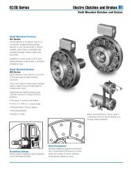
Clutch - Arten Freios e Embreagens Industriais
Clutch - Arten Freios e Embreagens Industriais
Clutch - Arten Freios e Embreagens Industriais
- No tags were found...

Create successful ePaper yourself
Turn your PDF publications into a flip-book with our unique Google optimized e-Paper software.
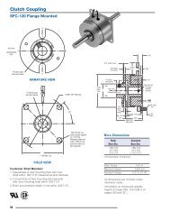
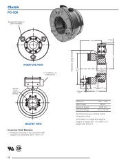
<strong>Clutch</strong><br />
SF-120 Flange Mounted<br />
For Bore sizes see<br />
chart below.<br />
.156<br />
.035/.004 (Std.)<br />
.020/.008 (Anti.)<br />
When New<br />
Std. Arm.<br />
Antibacklash Arm.<br />
.072 (Std.)<br />
.072 (Anti.)<br />
.020<br />
.000<br />
*<br />
12<br />
.062<br />
ARMATURE VIEW<br />
1.234<br />
Max. Dia.<br />
.502<br />
.500<br />
.031<br />
.375<br />
(Std.)<br />
.375<br />
(Anti.)<br />
Std. Arm<br />
Antibacklash Arm<br />
.109<br />
.065/.062 dia.<br />
2 holes equally<br />
spaced<br />
For Bore sizes see<br />
chart below.<br />
1.499/1.497<br />
Pilot Dia.<br />
45°<br />
.515<br />
.511<br />
.375<br />
(Std.)<br />
.375<br />
(Anti.)<br />
.528<br />
.072 (Std.)<br />
.072 (Anti.)<br />
.546<br />
.625<br />
.019<br />
.000<br />
#4-40<br />
UNC-3A<br />
.187<br />
Max.<br />
1.171 Max.<br />
.130/.123 dia.<br />
4 holes equally<br />
spaced on 1.312<br />
dia. B.C.*<br />
* Mounting holes are within .006 of true<br />
position relative to pilot diameter.<br />
Bore Dimensions<br />
1.140 Max. Sq.<br />
FIELD VIEW<br />
Customer Shall Maintain:<br />
1. Squareness of field mounting face with shaft with .003 T.I.R.<br />
measured at pilot dia.<br />
2. Concentricity of field mounting pilot diameter with rotor<br />
mounting shaft within .003 T.I.R.<br />
Static Torque<br />
Rotor<br />
Bore Dia.<br />
Maximum Speed<br />
Armature<br />
Bore Dia.<br />
.188/.187 .195/.190<br />
.251/.250 .257/.252<br />
.313/.312 —<br />
5 lb.in.<br />
3,600 rpm<br />
Standard Voltage D.C. 6, 24, 90<br />
All dimensions are nominal unless<br />
otherwise noted.<br />
Information on inertia and weights<br />
begins on page 239. Coil data is on<br />
pages 250 and 251.<br />
14
SF series<br />
Drawing I-25508<br />
<strong>Clutch</strong><br />
SF-120 Flange Mounted<br />
4<br />
1B<br />
2<br />
1A-2<br />
1A-1<br />
3<br />
1A<br />
Item Description Part Number Qty.<br />
1A Armature and Hub<br />
1A-1 Armature Hub 1<br />
3/16" Bore 5602-541-009<br />
1/4" Bore 5602-541-008<br />
1A-2 Armature 110-0110 1<br />
1B Antibacklash Armature 1<br />
3/16" Bore 5602-111-002<br />
1/4" Bore 5602-111-003<br />
5/16" Bore 5602-111-007<br />
2 Rotor 1<br />
3/16" Bore 5602-751-004<br />
1/4" Bore 5602-751-002<br />
5/16" Bore 5602-751-003<br />
3 Mounting Accessory 5101-101-001 1<br />
4 Field 1<br />
6 Volt 5602-451-003<br />
24 Volt 5602-451-005<br />
90 Volt 5602-451-007<br />
How to Order:<br />
1. Specify Type of Armature Desired.<br />
2. Specify Bore Size for Item 1A-1 or 1B<br />
and Item 2.<br />
3. Specify Voltage for Item 4.<br />
4. See Controls Section.<br />
Example:<br />
SF-120 <strong>Clutch</strong> per I-25508 - 90 Volt<br />
Standard Armature<br />
1/4" Armature Hub Bore<br />
1/4" Rotor Bore<br />
These units meet standards set forth in<br />
UL508 and are listed under guide card<br />
#NMTR2, file #59164.<br />
These units are CSA certified under file<br />
#LR11543.<br />
Refer to Service Manual P-200.<br />
15
<strong>Clutch</strong><br />
SF-120 Bearing Mounted<br />
.156<br />
Std. Arm.<br />
Antibacklash<br />
Arm.<br />
When New<br />
.035/.004 (Std.)<br />
.020/.008 (Anti.)<br />
.072 (Std.)<br />
.072 (Anti.)<br />
.020<br />
.000<br />
12<br />
.062<br />
.218<br />
.031 .375<br />
(Std.)<br />
.375<br />
(Anti.)<br />
*<br />
For Bore sizes<br />
see chart below.<br />
.502<br />
.500<br />
ARMATURE VIEW<br />
1.234<br />
Max. Dia.<br />
Std. Arm<br />
Antibacklash Arm<br />
.687<br />
For Bore sizes<br />
see chart below.<br />
.562<br />
.562<br />
45°<br />
.125<br />
.515<br />
.511<br />
.375<br />
(Std.)<br />
.375<br />
(Anti.)<br />
.072 (Std.)<br />
.072 (Anti.)<br />
.528<br />
Max.<br />
1.406 Max.<br />
.035/.004 (Std.)<br />
.020/.008 (Anti.)<br />
.781<br />
.859<br />
.093<br />
*Customer shall maintain dimension as noted.<br />
Bore Dimensions<br />
.578<br />
.703<br />
Rotor<br />
Bore Dia.<br />
Armature<br />
Bore Dia.<br />
.188/.187 .195/.190<br />
.251/.250 .257/.252<br />
.313/.312 —<br />
FIELD VIEW<br />
Static Torque<br />
Maximum Speed<br />
5 lb.in.<br />
3,600 rpm<br />
Standard Voltage D.C. 6, 24, 90<br />
All dimensions are nominal unless<br />
otherwise noted.<br />
Information on inertia and weights<br />
begins on page 239. Coil data is on<br />
pages 250 and 251.<br />
16
SF series<br />
Drawing I-25509<br />
<strong>Clutch</strong><br />
SF-120 Bearing Mounted<br />
4<br />
3<br />
1B<br />
2<br />
1A-2<br />
1A-1<br />
1A<br />
Item Description Part Number Qty.<br />
1A Armature and Hub<br />
1A-1 Armature Hub 1<br />
3/16" Bore 5602-541-009<br />
1/4" Bore 5602-541-008<br />
1A-2 Armature 110-0110 1<br />
1B Antibacklash Armature 1<br />
3/16" Bore 5602-111-002<br />
1/4" Bore 5602-111-003<br />
5/16" Bore 5602-111-007<br />
2 Rotor 1<br />
3/16" Bore 5602-751-008<br />
1/4" Bore 5602-751-006<br />
5/16" Bore 5602-751-007<br />
3 Field 1<br />
6 Volt 5602-451-021<br />
24 Volt 5602-451-023<br />
90 Volt 5602-451-025<br />
4 Set Collar 5602-266-001 1<br />
How to Order:<br />
1. Specify Type of Armature Desired.<br />
2. Specify Bore Size for Item 1A-1 or 1B<br />
and Item 2.<br />
3. Specify Voltage for Item 3.<br />
4. See Controls Section.<br />
Example:<br />
SF-120 <strong>Clutch</strong> per I-25509 - 90 Volt<br />
Standard Armature<br />
1/4" Armature Hub Bore<br />
These units meet standards set forth in<br />
UL508 and are listed under guide card<br />
#NMTR2, file #59164.<br />
These units are CSA certified under file<br />
#LR11543.<br />
Refer to Service Manual P-200.<br />
17
<strong>Clutch</strong><br />
SF-170 Flange Mounted<br />
When New<br />
.035/.004 (Std.)<br />
.021/.009 (Anti.)<br />
.375<br />
Std. Arm.<br />
.086 (Std.)<br />
.094 (Anti.)<br />
12<br />
.062<br />
Antibacklash<br />
Arm.<br />
.031<br />
.484<br />
(Std.)<br />
.390<br />
(Anti.)<br />
For Bore sizes<br />
see chart below.<br />
.751<br />
.750<br />
ARMATURE VIEW<br />
1.718<br />
Max. Dia.<br />
Std. Arm<br />
Anti. Arm<br />
.751/.750 pilot<br />
dia. backing<br />
plate only<br />
For Bore sizes & Keyway<br />
sizes see chart below.<br />
2.437<br />
2.435<br />
45°<br />
Pilot<br />
Dia.<br />
.633<br />
.629<br />
.484 (Std.)<br />
.390 (Anti.)<br />
.086<br />
(Std.)<br />
.094<br />
(Anti.)<br />
.632<br />
.040<br />
.000<br />
*<br />
.035/.004<br />
.021/.009<br />
.187<br />
.750<br />
1<br />
1.703 Max.<br />
#8-32<br />
UNC-3A<br />
.160<br />
.150<br />
.437<br />
Max.<br />
*Diameter over knurl.<br />
Rotor Bore Dimensions<br />
1.812<br />
FIELD VIEW<br />
Customer Shall Maintain:<br />
1. Squareness of field mounting face with shaft with .003 T.I.R.<br />
measured at pilot diameter.<br />
2. Concentricity of field mounting pilot diameter with rotor<br />
mounting shaft within .003 T.I.R.<br />
.204/.187 dia. 4 holes equally<br />
spaced on 2.125 diameter.<br />
Mounting holes are within<br />
.010 of true position relative<br />
to pilot diameter.<br />
Rotor Keyway Armature<br />
Bore Dia.<br />
Bore Dia.<br />
.251/.250 .062/.031 .2522/.2507<br />
.313/.312 .062/.031 .3145/.3130<br />
.376/.375 .093/.047 .3773/.3755<br />
Static Torque<br />
Maximum Speed<br />
15 lb.in.<br />
5,000 rpm<br />
Standard Voltage D.C. 6, 24, 90<br />
All dimensions are nominal unless<br />
otherwise noted.<br />
Information on inertia and weights<br />
begins on page 239. Coil data is on<br />
pages 250 and 251.<br />
18
SF series<br />
Drawing I-25754<br />
<strong>Clutch</strong><br />
SF-170 Flange Mounted<br />
4<br />
2<br />
1A<br />
1A-3<br />
1A-2<br />
3<br />
1A-1<br />
1B<br />
Item Description Part Number Qty.<br />
1A Armature and Hub<br />
1A-1 Armature Hub 1<br />
1/4" Bore 5123-541-002<br />
5/16" Bore 5123-541-003<br />
3/8" Bore 5123-541-004<br />
1A-2 Armature 110-0111 1<br />
1A-3 Release Spring 808-0019 1<br />
1B Antibacklash Armature 1<br />
1/4" Bore 5603-111-033<br />
5/16" Bore 5603-111-034<br />
3/8" Bore 5603-111-035<br />
2 Rotor 1<br />
1/4" Bore 5603-751-028<br />
5/16" Bore 5603-751-029<br />
3/8" Bore 5603-751-030<br />
3 Mounting Accessory 5102-101-001 1<br />
4 Field 1<br />
6 Volt 5603-451-047<br />
24 Volt 5603-451-049<br />
90 Volt 5603-451-051<br />
How to Order:<br />
1. Specify Type of Armature Desired.<br />
2. Specify Bore Size for Item 1A-1 or 1B and<br />
Item 2.<br />
3. Specify Voltage for Item 4.<br />
4. See Controls Section.<br />
Example:<br />
SF-170 <strong>Clutch</strong> per I-25754 - 90 Volt<br />
Antibacklash Armature<br />
1/4" Armature Hub Bore<br />
1/4" Rotor Bore<br />
These units meet standards set forth in<br />
UL508 and are listed under guide card<br />
#NMTR2, file #59164.<br />
These units are CSA certified under file<br />
#LR11543.<br />
Refer to Service Manual P-200.<br />
19
<strong>Clutch</strong><br />
SF-170 Bearing Mounted<br />
.086 (Std.)<br />
.094 (Anti.)<br />
1.203<br />
.375<br />
Std. Arm.<br />
Antibacklash<br />
Arm.<br />
.031<br />
.035/.004 (Std.)<br />
.021/.009 (Anti.)<br />
When New<br />
.040/.000*<br />
.484<br />
(Std.)<br />
.390<br />
(Anti.)<br />
12<br />
.062<br />
For Bore sizes<br />
see chart below.<br />
.751<br />
.750<br />
.093<br />
ARMATURE VIEW<br />
1.718<br />
Max.<br />
Dia.<br />
Std. Arm.<br />
Anti. Arm.<br />
.625<br />
.500<br />
.187<br />
.633†<br />
.629<br />
For Bore sizes see<br />
chart below.<br />
.484 (Std.)<br />
.390<br />
(Anti.)<br />
.632<br />
Max.<br />
.086 (Std.)<br />
.094 (Anti.)<br />
1.093<br />
.250<br />
1.062<br />
1.375<br />
1.906 Max.<br />
Bore Dimensions<br />
Rotor<br />
Bore Dia.<br />
Armature<br />
Bore Dia.<br />
.251/.250 .2522/.2507<br />
.313/.312 .3145/.3130<br />
.376/.375 .3773/.3755<br />
Customer Shall Maintain:<br />
1.750 Max. Dia.<br />
FIELD VIEW<br />
*Customer shall maintain dimension as noted.<br />
† over knurl<br />
Static Torque<br />
Maximum Speed<br />
15 lb.in.<br />
5,000 rpm<br />
Standard Voltage D.C. 6, 24, 90<br />
All dimensions are nominal unless<br />
otherwise noted.<br />
Information on inertia and weights<br />
begins on page 239. Coil data is on<br />
pages 250 and 251.<br />
20
SF series<br />
Drawing I-25755<br />
4<br />
<strong>Clutch</strong><br />
SF-170 Bearing Mounted<br />
3<br />
2<br />
1A<br />
1A-3<br />
1A-2<br />
1A-1<br />
1B<br />
Item Description Part Number Qty.<br />
1A Armature and Hub<br />
1A-1 Armature Hub 1<br />
1/4" Bore 5123-541-002<br />
5/16" Bore 5123-541-003<br />
3/8" Bore 5123-541-004<br />
1A-2 Armature 110-0111 1<br />
1A-3 Release Spring `808-0019 1<br />
1B Antibacklash Armature 1<br />
1/4" Bore 5603-111-033<br />
5/16" Bore 5603-111-034<br />
3/8" Bore 5603-111-035<br />
2 Rotor 1<br />
1/4" Bore 5603-751-019<br />
5/16" Bore 5603-751-021<br />
3/8" Bore 5603-751-020<br />
3 Field 1<br />
6 Volt 5603-451-039<br />
24 Volt 5603-451-041<br />
90 Volt 5603-451-043<br />
4 Retainer Ring 748-0024 1<br />
How to Order:<br />
1. Specify Type of Armature Desired.<br />
2. Specify Bore Size for Item 1A-1 or 1B<br />
and Item 2.<br />
3. Specify Voltage for Item 3.<br />
4. See Controls Section.<br />
Example:<br />
SF-170 <strong>Clutch</strong> per I-25755 - 90 Volt<br />
Antibacklash Armature<br />
1/4" Armature Hub Bore<br />
These units meet standards set forth in<br />
UL508 and are listed under guide card<br />
#NMTR2, file #59164.<br />
These units are CSA certified under file<br />
#LR11543.<br />
Refer to Service Manual P-200.<br />
21
<strong>Clutch</strong><br />
SF-250 Flange Mounted<br />
For Bore & Keyway sizes<br />
see chart below.<br />
.343 Max.<br />
.015 When New<br />
1.250<br />
1.125<br />
.468<br />
.380/.370<br />
.062<br />
ARMATURE VIEW<br />
2.625<br />
Max. Dia.<br />
1.376<br />
1.375<br />
Dia.<br />
.750<br />
Dia.<br />
.171<br />
1.063<br />
1.061<br />
Pilot<br />
Dia.<br />
24°<br />
8-32 UNC-3A<br />
For Bore & Keyway<br />
sizes see chart<br />
below.<br />
.437<br />
12°<br />
.437<br />
.062<br />
1.453 Min.<br />
.135*<br />
.095<br />
2 .750<br />
.437<br />
Max.<br />
3.281 Max.<br />
2.625 Sq.<br />
*Customer shall maintain dimension as noted.<br />
Bore and Keyway Dimensions<br />
3.500<br />
3.498<br />
Pilot Dia.<br />
FIELD VIEW<br />
Customer Shall Maintain:<br />
1. Squareness of field mounting face with shaft within .003<br />
T.I.R. measured at pilot diameter.<br />
2. Concentricity of field mounting pilot diameter with rotor<br />
mounting shaft within .003 T.I.R.<br />
*Mounting holes are within .010 of true position relative to pilot<br />
diameter.<br />
45°<br />
.204/.187 dia. (4) holes<br />
equally<br />
spaced on 3.125 dia.*<br />
Armature Keyway Rotor Keyway<br />
Bore Dia.<br />
Bore Dia.<br />
.3750/.3745 .376/.375 .093 x .046<br />
.5000/.4995 .312 x .156 .438/.437 .125 x .031<br />
*.5625/.5620 x 1.250 .501/.500 .125 x .031<br />
.6250/.6245<br />
*Available on special order only.<br />
Static Torque<br />
Maximum Speed<br />
70 lb.in.<br />
7,500 rpm<br />
Standard Voltage D.C. 6, 24, 90<br />
All dimensions are nominal unless otherwise noted.<br />
Information on inertia and weights begins on page<br />
239. Coil data is on pages 250 and 251.<br />
22
SF series<br />
Drawing I-25520<br />
<strong>Clutch</strong><br />
SF-250 Flange Mounted<br />
5-1<br />
5<br />
4<br />
2<br />
3<br />
1<br />
6<br />
Item Description Part Number Qty.<br />
1 Armature Hub 1<br />
3/8" Bore 5124-541-002<br />
1/2" Bore 5124-541-003<br />
5/8" Bore 5124-541-005<br />
2 Armature 5124-111-001 1<br />
3 Release Spring 5103-101-003 1<br />
4 Rotor 1<br />
3/8" Bore 5103-751-008<br />
1/2" Bore 5103-751-010<br />
5 Field 1<br />
6 Volt 5103-451-002<br />
24 Volt 5103-451-004<br />
90 Volt 5103-451-007<br />
5-1 Terminal Accessory 5103-101-002 1<br />
6 Mounting Accessory 5102-101-001 1<br />
How to Order:<br />
1. Specify Bore Size for Item 1 and Item 4.<br />
2. Specify Voltage for Item 5.<br />
3. See Controls Section.<br />
Example:<br />
SF-250 <strong>Clutch</strong> per I-25520 - 90 Volt<br />
3/8" Armature Hub Bore<br />
3/8" Rotor Bore<br />
These units meet standards set forth in<br />
UL508 and are listed under guide card<br />
#NMTR2, file #59164.<br />
These units are CSA certified under file<br />
#LR11543.<br />
Refer to Service Manual P-200.<br />
23
<strong>Clutch</strong><br />
SF-250 Bearing Mounted<br />
For Bore & Keyway sizes<br />
see chart below.<br />
.343 Max.<br />
.015 When New<br />
1.437<br />
1.125<br />
.468<br />
.171 + .062<br />
- 0<br />
.062<br />
2.625<br />
Max. Dia.<br />
1.376<br />
1.375<br />
Dia.<br />
.750<br />
Dia.<br />
.609<br />
Dia.<br />
ARMATURE VIEW<br />
45°<br />
24°<br />
.500<br />
12°<br />
.437<br />
.062<br />
1.453 Min.<br />
2<br />
3.468 Max.<br />
.125*<br />
.085<br />
*Customer shall maintain dimension as noted.<br />
1.312<br />
.171<br />
.187<br />
.187 1.562<br />
Rad.<br />
.937<br />
1.750<br />
Max.<br />
Bore and Keyway Dimensions<br />
Armature Keyway Rotor Keyway<br />
Bore Dia.<br />
Bore Dia.<br />
.3750/.3745 .376/.375 .093 x .046<br />
.5000/.4995 .312 x .156 .438/.437* .125 x .062<br />
.5625/.5620* x 1.25 .501/.500 .125 x .062<br />
.6250/.6245<br />
* Available on special order only.<br />
Static Torque<br />
Maximum Speed<br />
70 lb.in.<br />
7,500 rpm<br />
Standard Voltage D.C. 6, 24, 90<br />
For Bore & Keyway<br />
sizes see chart below.<br />
FIELD VIEW<br />
All dimensions are nominal unless otherwise noted.<br />
Information on inertia and weights begins on page 239. Coil<br />
data is on pages 250 and 251.<br />
24
SF Series<br />
Drawing I-25521<br />
4<br />
(Shipped Assembled)<br />
<strong>Clutch</strong><br />
SF-250 Bearing Mounted<br />
4-5<br />
4-4-1<br />
4-4<br />
4-2<br />
4-1<br />
4-2<br />
4-3<br />
3<br />
2<br />
1<br />
Item Description Part Number Qty.<br />
1 Armature Hub 1<br />
3/8" Bore 5124-541-002<br />
1/2" Bore 5124-541-003<br />
5/8" Bore 5124-541-005<br />
2 Release Spring Optional 5103-101-003 1<br />
3 Armature 5124-111-001 1<br />
4 Field and Rotor Assembly 1<br />
6 Volt – 3/8" Bore 5103-452-002<br />
24 Volt – 3/8" Bore 5103-452-004<br />
90 Volt – 3/8" Bore 5103-452-007<br />
6 Volt – 1/2" Bore 5103-452-016<br />
24 Volt – 1/2" Bore 5103-452-018<br />
90 Volt – 1/2" Bore 5103-452-021<br />
4-1 Rotor 1<br />
3/8" Bore 5103-751-014<br />
1/2" Bore 5103-751-016<br />
4-2 Retainer Ring 748-0371 2<br />
4-3 Ball Bearing 166-0108 1<br />
4-4 Field 1<br />
6 Volt 5103-451-018<br />
24 Volt 5103-451-020<br />
90 Volt 5103-451-023<br />
4-4-1 Terminal Accessory 5103-101-002 1<br />
4-5* Set Collar 266-0005 1<br />
*Used with 1/2" Bore only.<br />
How to Order:<br />
1. Specify Bore Size for Item 1 and Item 4.<br />
2. Specify Voltage for Item 4.<br />
3. See Controls Section.<br />
Example:<br />
SF-250 <strong>Clutch</strong> per I-25521 - 90 Volt<br />
1/2" Armature Hub Bore<br />
1/2" Rotor Bore<br />
These units meet standards set forth in<br />
UL508 and are listed under guide card<br />
#NMTR2, file #59164.<br />
These units are CSA certified under file<br />
#LR11543.<br />
Refer to Service Manual P-200.<br />
25
<strong>Clutch</strong><br />
SF-400 Flange Mounted<br />
For Bore & Keyway sizes<br />
see chart below.<br />
1.546<br />
.937<br />
.015 When New<br />
ARMATURE VIEW<br />
3.562<br />
Removable plug in<br />
ends for 1/2"<br />
conduit.<br />
1.875<br />
.082*<br />
1.873<br />
.042<br />
Pilot Dia.<br />
For Bore &<br />
Keyway sizes<br />
4.687 Max.<br />
see chart<br />
1/4-20 UNCbelow.<br />
3A<br />
.328 Max.<br />
.062 1.468<br />
Min.<br />
1.125<br />
.093<br />
2.125<br />
1.312<br />
.192/.182<br />
1.500<br />
.609 Max.<br />
3.546 Max.<br />
4.250 Sq.<br />
Bore and Keyway Dimensions<br />
5.625<br />
45°<br />
Armature Keyway Rotor Keyway<br />
5.623<br />
Pilot Dia.<br />
Bore Dia.<br />
Bore Dia.<br />
.5000/.4995 .312 x .156 .501/.500 .125 x.062<br />
.6250/.6245 x 1.25 .626/.625<br />
.296/.280 dia. (4) holes equally spaced on<br />
.7500/.7495 .751/.750 .187 x .093<br />
5.000 dia. Mounting holes are within .010<br />
of true position relative to pilot diameter.<br />
Static Torque<br />
270 lb.in.<br />
FIELD VIEW<br />
Maximum Speed<br />
4,500 rpm<br />
Customer Shall Maintain:<br />
Standard Voltage D.C. 6, 24, 90<br />
1. Squareness of field mounting face with shaft within .003<br />
All dimensions are nominal unless<br />
T.I.R. measured at pilot diameter.<br />
otherwise noted.<br />
2. Concentricity of field mounting pilot diameter with rotor<br />
mounting shaft within .003 T.I.R.<br />
Information on inertia and weights begins<br />
on page 239. Coil data is on pages 250<br />
*3. Customer shall maintain dimension as noted.<br />
and 251.<br />
26<br />
3.750<br />
4.234<br />
Max. Dia. 1.376<br />
1.375<br />
Dia.<br />
.875<br />
Dia.<br />
.250
SF series<br />
Drawing I-25695<br />
<strong>Clutch</strong><br />
SF-400 Flange Mounted<br />
6<br />
5-1<br />
5<br />
4<br />
2<br />
3<br />
7<br />
1<br />
Item Description Part Number Qty.<br />
1 Armature Hub 1<br />
1/2" Bore 5125-541-002<br />
5/8" Bore 5125-541-003<br />
3/4" Bore 5125-541-004<br />
2 Armature 5125-111-001 1<br />
3 Release Spring 5104-101-003 1<br />
4 Rotor 1<br />
1/2" Bore 5104-751-033<br />
5/8" Bore 5104-751-034<br />
3/4" Bore 5104-751-035<br />
5 Field 1<br />
6 Volt 5104-451-032<br />
24 Volt 5104-451-033<br />
90 Volt 5104-451-034<br />
5-1 Terminal Accessory 5103-101-002 1<br />
6 Conduit Box 5200-101-010 1<br />
7 Mounting Accessory 5104-101-002 1<br />
How to Order:<br />
1. Specify Bore Size for Items 1 and 4.<br />
2. Specify Voltage for Item 5.<br />
3. See Controls Section.<br />
Example:<br />
SF-400 <strong>Clutch</strong> per I-25695 - 90 Volt<br />
3/4" Armature Hub Bore<br />
3/4" Rotor Bore<br />
These units, when used in conjunction with the<br />
correct Warner Electric conduit box, meet the<br />
standards set of UL508 and are listed under<br />
guide card #NMTR2, file #59164.<br />
These units are CSA certified under file<br />
#LR11543<br />
Refer to Service Manual P-200.<br />
27
<strong>Clutch</strong><br />
SF-400 Bearing Mounted<br />
For Bore & Keyway<br />
sizes see chart below.<br />
1.546<br />
1.218<br />
.015 When New<br />
.062<br />
3.562<br />
ARMATURE VIEW<br />
28<br />
Removable plug in<br />
ends for 1/2"<br />
conduit.<br />
4.234<br />
3.750<br />
Max. Dia. 1.376 .875<br />
1.375<br />
Dia.<br />
.090<br />
Dia.<br />
*<br />
.050<br />
®U L<br />
45°<br />
.203<br />
For Bore &<br />
Keyway sizes see<br />
chart below. .062<br />
1.468<br />
Min.<br />
1.281<br />
.328<br />
.500<br />
4.687<br />
.328 Max. 1.812<br />
Max.<br />
.187<br />
2.125<br />
Dia.<br />
1.625<br />
.187<br />
3.859 Max.<br />
2.312 Rad.<br />
Bore and Keyway Dimensions<br />
.859<br />
Armature Keyway Rotor Keyway<br />
Bore Dia.<br />
Bore Dia.<br />
.501/.500 .125 x.062<br />
.5000/.4995 .312 x .156 .626/.625<br />
.6250/.6245 x 1.25 .751/.750 .187 x .093<br />
.7500/.7495 .876/.875<br />
1.001/1.000<br />
FIELD VIEW<br />
Static Torque<br />
270 lb.in.<br />
Maximum Speed<br />
4,500 rpm<br />
*Customer shall maintain dimension as noted.<br />
Standard Voltage D.C. 6, 24, 90<br />
All dimensions are nominal unless otherwise noted.<br />
Information on inertia and weights begins on page 239. Coil<br />
data is on pages 250 and 251.<br />
1.375<br />
Dia.
SF series<br />
Drawing I-25696<br />
<strong>Clutch</strong><br />
SF-400 Bearing Mounted<br />
5<br />
4<br />
(Shipped Assembled)<br />
4-4-1<br />
4-2<br />
4-4<br />
4-3<br />
4-1<br />
3<br />
2<br />
1<br />
Item Description Part Number Qty.<br />
1 Armature Hub 1<br />
1/2" Bore 5125-541-002<br />
5/8" Bore 5125-541-003<br />
3/4" Bore 5125-541-004<br />
2 Release Spring Optional 5104-101-003 1<br />
3 Armature 5125-111-001 1<br />
4 Field and Rotor Assembly 1<br />
6 Volt – 1/2" Bore 5104-452-052<br />
24 Volt – 1/2" Bore 5104-452-053<br />
90 Volt – 1/2" Bore 5104-452-054<br />
6 Volt – 5/8" Bore 5104-452-055<br />
24 Volt – 5/8" Bore 5104-452-056<br />
90 Volt – 5/8" Bore 5104-452-057<br />
6 Volt – 3/4" Bore 5104-452-058<br />
24 Volt – 3/4" Bore 5104-452-059<br />
90 Volt – 3/4" Bore 5104-452-060<br />
4-1 Rotor 1<br />
1/2" Bore 5104-751-043<br />
5/8" Bore 5104-751-044<br />
3/4" Bore 5104-751-045<br />
4-2 Retainer Ring 748-0018 1<br />
4-3 Ball Bearing 166-0150 1<br />
Item Description Part Number Qty.<br />
4-4 Field 1<br />
6 Volt 5104-451-038<br />
24 Volt 5104-451-039<br />
90 Volt 5104-451-040<br />
4-4-1 Terminal Accessory 5103-101-002 1<br />
5 Conduit Box 5200-101-010 1<br />
How to Order:<br />
1. Specify Bore Size for Items 1 and 4.<br />
2. Specify Voltage for Item 4.<br />
3. See Controls Section.<br />
Example:<br />
SF-400 <strong>Clutch</strong> per I-25696 - 90 Volt<br />
3/4" Armature Hub Bore<br />
3/4" Rotor Bore<br />
These units, when used in conjunction with the correct<br />
Warner Electric conduit box, meet standards set forth in<br />
UL508 and are listed under guide card #NMTR2, file #59164.<br />
These units are CSA certified under file #LR11543<br />
Service Manual P-200.<br />
29
<strong>Clutch</strong><br />
SF-500 Bearing Mounted<br />
See page 230 for details on<br />
Drive Pin mountings.<br />
3.781<br />
1.546<br />
1.234<br />
.062 When New<br />
.968 Min.<br />
.625<br />
.453<br />
4.093<br />
ARMATURE VIEW<br />
5.328<br />
Max.<br />
Dia.<br />
5.062<br />
Dia. 2.062 Dia.<br />
.187<br />
1.750 Dia.<br />
3.750<br />
45°<br />
Removable<br />
plug in ends for<br />
1/2" conduit.<br />
.125<br />
.750<br />
.218<br />
5.218<br />
1.343<br />
1.593<br />
2.093<br />
.281<br />
Bore and Keyway Dimensions<br />
3.156<br />
2.781<br />
Rotor<br />
Bore Dia.<br />
Keyway<br />
.751/.750 .187 x .093<br />
.876/.875<br />
.9385/.9375<br />
1.001/1.000 .250 x .125<br />
1.126/1.125<br />
1.251/1.250<br />
Customer Shall Maintain:<br />
1. Armature shafts to be concentric with<br />
rotor mounting shaft within .006 T.I.R.<br />
30<br />
FIELD VIEW<br />
For Bore & Keyway<br />
sizes see chart below.<br />
Static Torque<br />
Maximum Speed<br />
50 lb.ft.<br />
4,000 rpm<br />
Standard Voltage D.C. 6, 24, 90<br />
All dimensions are nominal unless<br />
otherwise noted.<br />
pages 250 and 251.<br />
®U L<br />
Information on inertia and weights<br />
begins on page 239. Coil data is on
SF series<br />
Drawing I-25715<br />
<strong>Clutch</strong><br />
SF-500 Bearing Mounted<br />
2<br />
4<br />
1<br />
5<br />
3-4<br />
3-3<br />
3-2<br />
3-1<br />
3<br />
(Shipped Assembled)<br />
Item Description Part Number Qty.<br />
1 Autogap Accessory 5200-101-009 3<br />
2 Armature 5300-111-002 1<br />
3 Field and Rotor Assembly 1<br />
6 Volt – 3/4" Bore 5200-452-002<br />
24 Volt – 3/4" Bore 5200-452-004<br />
90 Volt – 3/4" Bore 5200-452-005<br />
6 Volt – 7/8" Bore 5200-452-008<br />
24 Volt – 7/8" Bore 5200-452-010<br />
90 Volt – 7/8" Bore 5200-452-011<br />
24 Volt – 15/16" Bore 5200-452-016<br />
90 Volt – 15/16" Bore 5200-452-017<br />
6 Volt – 1" Bore 5200-452-020<br />
24 Volt – 1" Bore 5200-452-022<br />
90 Volt – 1" Bore 5200-452-023<br />
6 Volt – 1-1/8" Bore 5200-452-026<br />
24 Volt – 1-1/8" Bore 5200-452-028<br />
90 Volt – 1-1/8" Bore 5200-452-029<br />
6 Volt – 1-1/4" Bore 5200-452-032<br />
24 Volt – 1-1/4" Bore 5200-452-034<br />
90 Volt – 1-1/4" Bore 5200-452-035<br />
3-1 Rotor 1<br />
3/4" Bore 5200-751-002<br />
7/8" Bore 5200-751-003<br />
15/16" Bore 5200-741-004<br />
Item Description Part Number Qty.<br />
1" Bore 5200-751-005<br />
1-1/8" Bore 5200-751-006<br />
1-1/4" Bore 5200-751-007<br />
3-2 Field & Bearing Assembly 1<br />
6 Volt 5200-451-024<br />
24 Volt 5200-451-026<br />
90 Volt 5200-451-027<br />
3-3 Ball Bearing 166-0110 1<br />
3-4 Retainer Ring 748-0002 1<br />
4 Conduit Box 5200-101-010 1<br />
5 Terminal Accessory 5311-101-001 1<br />
How to Order:<br />
1. Specify Bore Size for Item 3.<br />
3. Specify Voltage for Item 3.<br />
4. See Controls Section.<br />
Example:<br />
SF-500 <strong>Clutch</strong> per I-25715 - 90 Volt<br />
3/4" Bore<br />
These units meet standards set forth in UL508 and are<br />
listed under guide card #NMTR2, file #59164.<br />
These units are CSA certified under file #LR11543.<br />
Refer to Service Manual P-202.<br />
31
<strong>Clutch</strong><br />
SF-650 Flange Mounted<br />
See page 230 for details on<br />
Drive Pin mountings.<br />
3.500<br />
1.546<br />
.937<br />
.062 when new<br />
.453<br />
.968<br />
.625<br />
Max.<br />
ARMATURE VIEW<br />
5/16-18<br />
UNC-3A<br />
4.625<br />
3.750<br />
Removable plug<br />
in ends for 1/2"<br />
conduit.<br />
6.687<br />
Max.<br />
Dia.<br />
6.500<br />
Dia.<br />
1<br />
.656<br />
2.822/2.820<br />
pilot<br />
dia.<br />
.358/.338 dia. (4)<br />
holes equally<br />
spaced on 7.250<br />
dia.*<br />
Mounting holes<br />
are within .010 of<br />
true position<br />
relative to pilot<br />
diameter.<br />
5.750 Max.<br />
4.375 Dia.<br />
45°<br />
8.000<br />
7.998<br />
6.500<br />
1.812<br />
.578<br />
Max.<br />
Customer Shall Maintain:<br />
1. Concentricity of field mounting pilot diameter with rotor<br />
mounting shaft within .006 T.I.R.<br />
2. Squareness of field mounting face with shaft within .006<br />
T.I.R. measured at field mounting bolt circle.<br />
3. Rotor mounting pilot diameter must be concentric with shaft<br />
within .006 T.I.R.<br />
32<br />
FIELD VIEW<br />
(Inside & Outside Mounted)<br />
.358/.338 dia. (4) holes<br />
equally spaced on 7.250 dia.*<br />
Shaft Size .500 – 1.625<br />
Static Torque<br />
Maximum Speed<br />
95 lb.ft.<br />
3,600 rpm<br />
Standard Voltage D.C. 6, 24, 90<br />
All dimensions are nominal unless<br />
otherwise noted.<br />
®U L<br />
Information on inertia and weights<br />
begins on page 239. Coil data is on<br />
pages 250 and 251.
SF series<br />
Drawing I-25749<br />
<strong>Clutch</strong><br />
SF-650 Flange Mounted<br />
5<br />
3<br />
8<br />
2<br />
7<br />
6A<br />
6A-1<br />
8<br />
6B-1<br />
1<br />
4<br />
6B<br />
7<br />
Item Description Part Number Qty.<br />
1 Armature Accessory 5181-101-010 4<br />
2 Armature 5281-111-002 1<br />
3 Rotor Hub & Mounting Acc. 5207-101-005 1<br />
4 Rotor 5281-751-001 1<br />
5 Bushing* 1<br />
1/2" to 1-5/8" Bore 180-0326 to 180-0344<br />
6A Field - Inside Mounted 1<br />
6 Volt 5207-451-009<br />
24 Volt 5207-451-012<br />
90 Volt 5207-451-011<br />
6A-1 Terminal Accessory 5311-101-001 1<br />
6B Field - Outside Mounted 1<br />
6 Volt 5207-451-003<br />
24 Volt 5207-451-006<br />
90 Volt 5207-451-005<br />
6B-1 Terminal Accessory 5311-101-001 1<br />
7 Mounting Accessory 5321-101-002 1<br />
8 Conduit Box 5200-101-010 1<br />
How to Order:<br />
1. Specify Bore Size for Item 5.<br />
2. Specify Voltage for Item 6.<br />
3. Specify Inside or Outside Mounted for Item 6.<br />
4. See Controls Section.<br />
Example:<br />
SF-650 <strong>Clutch</strong> per I-25749 - 90 Volt<br />
1" Bore<br />
These units, when used in conjunction with the correct<br />
Warner Electric conduit box, meet the standards of<br />
UL508 and are listed under guide card #NMTR, file<br />
#59164.<br />
These units are CSA certified under file #LR11543<br />
*See page 252 for specific part numbers.<br />
Refer to Service Manual P-202.<br />
33
<strong>Clutch</strong><br />
SF-650 Bearing Mounted<br />
See page 230 for details on<br />
Drive Pin mountings.<br />
3.500 Max.<br />
1.546<br />
.937<br />
.062 when new<br />
.453<br />
.968<br />
.625<br />
4.625<br />
ARMATURE VIEW<br />
3.750<br />
Removable plug in ends<br />
for 1/2" conduit.<br />
6.687<br />
Max.<br />
Dia.<br />
6.500<br />
Dia.<br />
1.250<br />
1.750<br />
.156<br />
6.359<br />
Dia.<br />
45°<br />
Reverse<br />
Mounting<br />
5.750<br />
.562<br />
.421<br />
Max.<br />
1/4-20 UNC-2A<br />
.312<br />
1.781<br />
.765<br />
Max.<br />
3.625 Max.<br />
3.750<br />
See page 252 for details on Bushings.<br />
Shaft Size .500 – 1.500<br />
Static Torque<br />
95 lb.ft.<br />
Maximum Speed<br />
3,600 rpm<br />
Standard Voltage D.C. 6, 24, 90<br />
34<br />
FIELD VIEW<br />
All dimensions are nominal unless<br />
otherwise noted.<br />
®U L<br />
Information on inertia and weights<br />
begins on page 239. Coil data is on<br />
pages 250 and 251.
SF series<br />
Drawing I-25750<br />
<strong>Clutch</strong><br />
SF-650 Bearing Mounted<br />
1<br />
6<br />
3-8<br />
3-9<br />
3-7<br />
2<br />
3-6-1<br />
3-6<br />
3-4<br />
3-5<br />
3-2<br />
3-3 4<br />
5<br />
3-1<br />
3<br />
(Shipped Assembled)<br />
Item Description Part Number Qty.<br />
1 Autogap Accessory 5181-101-010 4<br />
2 Armature 5281-111-002 1<br />
3 Field and Rotor Assembly 1<br />
6 Volt 5207-452-002<br />
24 Volt 5207-452-005<br />
90 Volt 5207-452-004<br />
3-1 Capscrew 797-0083 4<br />
3-2 Lockwasher 950-0355 4<br />
3-3 Rotor Assembly 5281-751-001 1<br />
3-4 Rotor Hub 540-0614 1<br />
3-5 Reverse Mounting Accessory 5201-101-005 1<br />
3-6 Field 1<br />
6 Volt 5281-451-002<br />
24 Volt 5281-451-004<br />
90 Volt 5281-451-005<br />
3-6-1 Terminal Accessory 5311-101-001 1<br />
3-7 Ball Bearing 166-0104 1<br />
3-8 Retainer Ring - External 748-0004 1<br />
3-9 Retainer Ring -Internal 748-0104 1<br />
Item Description Part Number Qty.<br />
4 Bushing* 1<br />
1/2" to 1-1/2" Bore 180-0002 to 180-0018<br />
†5 Torque Arm Accessory 5207-101-003 1<br />
6 Conduit Box 5200-101-010 1<br />
How to Order:<br />
1. Specify Voltage for Item 3.<br />
2. Specify Bore Size for Item 4.<br />
3. See Controls Section.<br />
Example:<br />
SF-650 <strong>Clutch</strong>, bearing mounted per I-25750 - 90 Volt,<br />
1" Bore<br />
These units, when used in conjunction with the correct<br />
Warner Electric conduit box, meet the standards of<br />
UL508 and are listed under guide card #NMTR, file<br />
#59164.<br />
These units are CSA certified under file #LR11543<br />
*See page 252 for specific part numbers.<br />
Refer to Service Manual P-202.<br />
†Optional – not included in price.<br />
35
<strong>Clutch</strong>–Normal Duty<br />
SF-825 Flange Mounted<br />
See page 230 for Drive<br />
Pin mountings.<br />
1.546<br />
.921<br />
5/16-18 UNC-3A<br />
5.656<br />
ARMATURE VIEW<br />
3.750<br />
Removable plug in<br />
ends for 1/2" conduit.<br />
8.656<br />
Max. Dia.<br />
3.562<br />
Dia.<br />
2.562<br />
Dia.<br />
1<br />
.562<br />
Max.<br />
.687<br />
2.253<br />
2.251<br />
Pilot Dia.<br />
3.503/3.501<br />
Pilot Dia.<br />
6.812 Max.<br />
.358/.338 dia. (6) holes<br />
equally spaced on<br />
4.250 dia.*<br />
.358/.338 dia. (4)<br />
holes equally spaced<br />
on 8.875 dia.*<br />
36<br />
.350/.341 dia. (6) holes<br />
equally spaced on 2.875<br />
dia.**<br />
FIELD VIEW<br />
(Inside & Outside Mounted)<br />
9.749/9.747<br />
Pilot Dia.<br />
Customer Shall Maintain:<br />
1. Concentricity of field mounting pilot diameter with<br />
rotor mounting shaft within .006 T.I.R.<br />
2. Squareness of field mounting face with shaft<br />
within .006 T.I.R. measured at field mounting bolt circle.<br />
.093<br />
When New<br />
.562<br />
1.312<br />
2.593<br />
Max.<br />
Shaft Size .500 – 1.250<br />
Static Torque<br />
Maximum Speed<br />
125 lb.ft.<br />
4,000 rpm<br />
Standard Voltage D.C. 6, 24, 90<br />
.602<br />
.586<br />
.281<br />
* Mounting holes are within .010 of true position<br />
relative to pilot diameter.<br />
** Mounting holes are within .008 of true position<br />
relative to pilot diameter.<br />
All dimensions are nominal unless<br />
otherwise noted.<br />
®U L<br />
Information on inertia and weights<br />
begins on page 239. Coil data is on<br />
pages 250 and 251.
Normal Duty<br />
Drawing I-25560<br />
<strong>Clutch</strong><br />
SF-825 Flange Mounted<br />
5<br />
1<br />
4<br />
3<br />
6<br />
9<br />
7A<br />
9<br />
8A<br />
7B<br />
2<br />
8B<br />
Item Description Part Number Qty.<br />
1 Armature 5301-111-018 1<br />
2 Autogap Accessory 5201-101-008 3<br />
3 Bushing* 1<br />
1/2" to 1-1/4" Bore 180-0101 to 180-0113<br />
4 Mounting Accessory 5201-101-007 1<br />
5 Rotor 1<br />
Standard Friction Material 5201-751-003<br />
†Optional LK Facing 5201-751-007<br />
6 Rotor Hub 540-0013 1<br />
7A Field - Inside Mounted 1<br />
6 Volt 5201-451-006<br />
24 Volt 5201-451-008<br />
90 Volt 5201-451-010<br />
7B Field - Outside Mounted 1<br />
6 Volt 5201-451-014<br />
24 Volt 5201-451-016<br />
90 Volt 5201-451-018<br />
8A Mounting Accessory - I.M. 5321-101-001 1<br />
8B Mounting Accessory - O.M. 5321-101-002 1<br />
9 Conduit Box 5200-101-012 1<br />
How to Order:<br />
1. Specify Bore Size for Item 3.<br />
2. Specify Voltage for Items 7A or 7B.<br />
3. Specify Inside Mounted for Items 7A and 8A or Outside<br />
Mounted for Items 7B and 8B.<br />
4. See Controls Section.<br />
Example:<br />
SF-825 <strong>Clutch</strong> per I-25560 -90 Volt, 1" Bore,<br />
Inside Mounted<br />
These units, when used in conjunction with the correct<br />
Warner Electric conduit box, meet the standards of UL508<br />
and are listed under guide card #NMTR, file #59164.<br />
These units are CSA certified under file #LR11543.<br />
*See page 252 for specific part numbers.<br />
Refer to Service Manual P-222.<br />
†Optional LK facing available. For more information, see<br />
page 232.<br />
37
<strong>Clutch</strong><br />
SF-825 Bearing Mounted<br />
See page 230 for details<br />
on Drive Pin Mountings.<br />
Normal Duty<br />
1.546<br />
.984<br />
5.656<br />
ARMATURE VIEW<br />
3.5625<br />
Dia.<br />
2.562<br />
Dia.<br />
1.250<br />
.156<br />
1.656<br />
8.656<br />
Max. Dia.<br />
3.750<br />
Removable plug in ends<br />
for 1/2" conduit.<br />
45°<br />
.875<br />
.093 When New<br />
.562<br />
1.296<br />
.187<br />
Reverse<br />
Mounting<br />
.343<br />
6.812 Max.<br />
2.687 Max.<br />
2.765 Max.<br />
5.00<br />
.350/.342<br />
Shaft Size .500 – 1.500<br />
Static Torque<br />
150 lb.ft.<br />
Maximum Speed<br />
3,600 rpm<br />
Standard Voltage D.C. 6, 24, 90<br />
38<br />
All dimensions are nominal unless<br />
See page 252 for details<br />
otherwise noted.<br />
on Bushings.<br />
Information on inertia and weights<br />
begins on page 239. Coil data is on<br />
FIELD VIEW<br />
pages 250 and 251.<br />
®U L
Normal Duty<br />
Drawing I-25575<br />
<strong>Clutch</strong><br />
SF-825 Bearing Mounted<br />
5<br />
4-6<br />
4-3-1<br />
1<br />
4-3<br />
4-1<br />
4-2<br />
4-4<br />
2<br />
4<br />
(Shipped Assembled)<br />
3<br />
Item Description Part Number Qty.<br />
1 Armature 5301-111-018 1<br />
2 Autogap Accessory 5201-101-008 3<br />
3 Bushing* 1<br />
1/2" to 1-1/2" Bore 180-0002 to 180-0018<br />
4 Field & Rotor Assembly 1<br />
6 Volt 5201-452-002<br />
24 Volt 5201-452-004<br />
90 Volt 5201-452-006<br />
4-1 Rotor 1<br />
Standard Friction Material 5201-751-008<br />
4-2 Mounting Accessory 5201-101-005 1<br />
4-3 Field & Bearing Assembly 1<br />
6 Volt 5201-451-054<br />
24 Volt 5201-451-056<br />
90 Volt 5201-451-057<br />
4-3-1 Ball Bearing 166-0142 1<br />
4-4 Retainer Ring 748-0111 1<br />
4-6 Retainer Ring 748-0016 1<br />
5 Conduit Box 5200-101-012 1<br />
How to Order:<br />
1. Specify Bore Size for Item 3.<br />
2. Specify Voltage for Item 4.<br />
4. See Controls Section.<br />
Example:<br />
SF-825 <strong>Clutch</strong> per I-25575 - 90 Volt, 1" Bore<br />
These units, when used in conjunction with the correct<br />
Warner Electric conduit box, meet the standards of<br />
UL508 and are listed under guide card #NMTR, file<br />
#59164. These units are CSA certified under file<br />
#LR11543.<br />
*See page 252 for specific part numbers.<br />
Refer to Service Manual P-215.<br />
39
<strong>Clutch</strong><br />
SF-825 Flange Mounted<br />
Heavy Duty<br />
.271/.263 dia. 5 holes (hub) equally spaced on 2.015 dia. Mounting<br />
holes are within .003 of true position relative to pilot dia.<br />
1.546<br />
.921<br />
ARMATURE VIEW<br />
3.750<br />
1.640 dia.<br />
Removable plug in ends<br />
for 1/2" conduit.<br />
.093 Max. Length<br />
of Customer Pilot.<br />
5/16-18 UNC-3A<br />
5.656<br />
6.812 Max.<br />
3.503/3.501<br />
Pilot Dia.<br />
See page 252 for details<br />
on bushings.<br />
8.656<br />
Max.<br />
Dia.<br />
4.250<br />
Dia.<br />
2.313<br />
2.311<br />
Pilot<br />
1.343<br />
1.00<br />
.687<br />
.562<br />
Max.<br />
2.253<br />
2.251<br />
Pilot<br />
.358/.338 dia. (6)<br />
holes equally spaced<br />
on 4.250 dia.<br />
Mounting holes are<br />
within .010 of true<br />
position relative to<br />
pilot dia.<br />
1/4-28 UNF-<br />
3A<br />
.062<br />
.125<br />
9.749/9.747<br />
Pilot Dia.<br />
.468 Max.<br />
.531<br />
1.312<br />
3.765 Max.<br />
.602/.586<br />
.281<br />
.358/.338 dia. (4) holes<br />
equally spaced on 8.875<br />
dia. are within .010 of true<br />
position relative to pilot dia.<br />
Customer Shall Maintain:<br />
1. Concentricity of field mounting pilot diameter with rotor<br />
mounting shaft within .006 T.I.R.<br />
2. Squareness of field mounting face with shaft within .006<br />
T.I.R. measured at field mounting bolt circle.<br />
3. Rotor mounting shaft concentric with armature hub pilot<br />
diameter within .010 T.I.R.<br />
When Hub is Furnished by Customer:<br />
Rotor mounting pilot diameter must be concentric with rotor<br />
mounting shaft within .006 T.I.R.<br />
40<br />
.350/.341 dia. (6) holes equally spaced on 2.875<br />
dia. Mounting holes are within .008 of true<br />
position relative to pilot dia.<br />
FIELD VIEW<br />
(Inside & Outside Mounted)<br />
Shaft Size .500 – 1.250<br />
Static Torque<br />
Maximum Speed<br />
125 lb.ft.<br />
4,000 rpm<br />
Standard Voltage D.C. 6, 24, 90<br />
All dimensions are nominal unless<br />
otherwise noted.<br />
®U L<br />
Information on inertia and weights<br />
begins on page 239. Coil data is on<br />
pages 250 and 251.
Heavy Duty<br />
Drawing I-25561<br />
3<br />
(Shipped<br />
Assembled)<br />
3-5<br />
<strong>Clutch</strong><br />
SF-825 Flange Mounted<br />
3-3<br />
3-6<br />
9A<br />
10<br />
3-2<br />
8A<br />
1<br />
3-4<br />
10<br />
3-1<br />
2<br />
5<br />
6<br />
9B<br />
7<br />
8B<br />
4<br />
Item Description Part # Qty.<br />
1 Splined Hub 540-0146 1<br />
2 Mounting Accessory 5201-101-001 1<br />
3 Armature & Splined Adapter 5201-111-001 1<br />
3-1 Armature 5321-111-022 1<br />
3-2 Splined Adapter 104-0008 1<br />
3-3 Autogap Accessory 5321-101-006 1<br />
3-4 Screw 797-0341 3<br />
3-5 Locknut 661-0004 3<br />
3-6 Spacer 748-0333 3<br />
4 Mounting Accessory 5201-101-007 1<br />
5 Rotor 1<br />
Standard Friction Material 5201-751-003<br />
†Optional LK Facing 5201-751-007<br />
6 Bushing, Taperlock* 180-0101 to 180-0113 1<br />
7 Rotor Hub 540-0013 1<br />
8A Mounting Accessory, I.M. 5321-101-001 1<br />
8B Mounting Accessory, O.M. 5321-101-002 1<br />
9A Field, Inside Mounted 1<br />
6 Volt 5201-451-006<br />
24 Volt 5201-451-008<br />
90 Volt 5201-451-010<br />
Item Description Part # Qty.<br />
9B Field, Outside Mounted 1<br />
6 Volt 5201-451-014<br />
24 Volt 5201-451-016<br />
90 Volt 5201-451-018<br />
10 Conduit Box 5200-101-012 1<br />
How to Order:<br />
1. Specify Bore Size for Item 6.<br />
2. Specify Voltage for Item 9A or 9B.<br />
3. Specify Inside Mounted for Items 8A and 9A or Outside<br />
Mounted for Items 8B and 9B.<br />
4. See Controls Section.<br />
Example:<br />
SF-825 <strong>Clutch</strong> Coupling, Heavy Duty, per I-25561 -<br />
90 Volt, Inside Mounted, 1" Bore (Item 6)<br />
These units, when used in conjunction with the correct<br />
Warner Electric conduit box, meet the standards of<br />
UL508 and are listed under guide card #NMTR, file<br />
#59164. These units are CSA certified under file<br />
#LR11543<br />
*See page 252 for specific part numbers.<br />
Refer to Service Manual P-215.<br />
†Optional LK facing available. For more information,<br />
see page 232.<br />
41
<strong>Clutch</strong><br />
SF-825 Bearing Mounted<br />
Heavy Duty<br />
.271/.263 dia. 5 holes (hub) equally spaced<br />
on 2.015 dia. and within .003 of true<br />
position relation to 2.313/2.311 pilot dia.<br />
1.546<br />
.984<br />
.093<br />
Max. Length of<br />
Customer Pilot.<br />
5.656<br />
ARMATURE VIEW<br />
1.640<br />
8.656<br />
Max.<br />
Dia.<br />
4.250<br />
Dia.<br />
2.313<br />
2.311<br />
Dia.<br />
1.343<br />
1/4-28<br />
UNF-3A<br />
1.250<br />
1.656<br />
3.750<br />
Removable plug in ends<br />
of 1/2" conduit.<br />
45°<br />
.062<br />
.875<br />
.343<br />
6.812<br />
.531<br />
.125<br />
1.296<br />
5<br />
.468 Dia.<br />
.156<br />
3.953<br />
Max.<br />
.187<br />
.350<br />
FIELD VIEW<br />
See page 252 for details<br />
on Bushings.<br />
Shaft Size .500 – 1.500<br />
Static Torque<br />
150 lb.ft.<br />
Maximum Speed<br />
3,600 rpm<br />
Standard Voltage D.C. 6, 24, 90<br />
Customer Shall Maintain:<br />
1. Armature hub pilot diameter to be concentric<br />
with field and rotor mounting shaft within .010<br />
T.I.R.<br />
42<br />
All dimensions are nominal unless<br />
otherwise noted.<br />
®U L<br />
Information on inertia and weights<br />
begins on page 239. Coil data is on<br />
pages 250 and 251.
Heavy Duty<br />
Drawing I-25573<br />
<strong>Clutch</strong><br />
SF-825 Bearing Mounted<br />
3<br />
(Shipped Assembled)<br />
3-5<br />
6<br />
4-3-1<br />
4-6<br />
3-6<br />
4-4<br />
3-3<br />
3-4<br />
3-2<br />
4-3<br />
3-1<br />
4-1<br />
4-2<br />
1<br />
2<br />
4<br />
(Shipped Assembled)<br />
5<br />
Item Description Part Number Qty.<br />
1 Splined Hub 540-0146 1<br />
2 Accessory, Mounting 5201-101-001 1<br />
3 Armature & Adapter Assembly 5201-111-001 1<br />
3-1 Armature 5321-111-022 1<br />
3-2 Splined Adapter 104-0008 1<br />
3-3 Autogap Accessory 5321-101-006 1<br />
3-4 Screw 797-0341 3<br />
3-5 Locknut 661-0004 3<br />
3-6 Spacer 748-0333 3<br />
4 Field & Rotor Assembly 1<br />
6 Volt 5201-452-002<br />
24 Volt 5201-452-004<br />
90 Volt 5201-452-006<br />
4-1 Rotor 5201-751-008 1<br />
4-2 Mounting Accessory 5201-101-005 1<br />
4-3 Field & Bearing Assembly 1<br />
6 Volt 5201-451-054<br />
24 Volt 5201-451-056<br />
90 Volt 5201-451-057<br />
Item Description Part Number Qty.<br />
4-3-1 Ball Bearing 166-0142 1<br />
4-4 Retainer Ring 748-0111 1<br />
4-6 Retainer Ring 748-0016 1<br />
5 Bushing* 180-0002 to<br />
180-0018 1<br />
6 Conduit Box 5200-101-012 1<br />
How to Order:<br />
1. Specify Bore Size for Item 5.<br />
2. Specify Voltage for Item 4.<br />
4. See Controls Section.<br />
Example:<br />
SF-825 <strong>Clutch</strong> per I-25573 - 90 Volt, 1" Bore<br />
These units, when used in conjunction with the correct<br />
Warner Electric conduit box, meet the standards of UL508<br />
and are listed under guide card #NMTR, file #59164.<br />
These units are CSA certified under file #LR11543.<br />
*See page 252 for specific part numbers.<br />
Refer to Service Manual P-215.<br />
43
<strong>Clutch</strong><br />
SF-1000 Flange Mounted<br />
Normal Duty<br />
See page 230<br />
for Drive Pin<br />
mountings.<br />
1.546<br />
.921<br />
5/16-18 UNC-3A<br />
6.531<br />
ARMATURE VIEW<br />
3.750<br />
Removable plug in ends<br />
for 1/2" conduit.<br />
10.328<br />
Max. Dia.<br />
5.252<br />
Dia.<br />
4.125<br />
Dia.<br />
1.250<br />
.562<br />
Max.<br />
.250<br />
4.128<br />
4.126<br />
Pilot Dia.<br />
5.378/5.376<br />
Pilot Dia.<br />
7.687 Max.<br />
.358/.338 dia. (6) holes<br />
equally spaced on<br />
6.125 dia.*<br />
.358/.338 dia. (8)<br />
holes equally spaced<br />
on 10.625 dia.*<br />
.350/.341 dia. (6) holes equally<br />
spaced on 4.875 dia.**<br />
FIELD VIEW<br />
(Inside & Outside Mounted)<br />
Customer Shall Maintain:<br />
1. Concentricity of field mounting pilot diameter with<br />
rotor mounting shaft within .006 T.I.R.<br />
11.500/11.498<br />
Pilot Dia.<br />
2. Squareness of field mounting face with shaft<br />
within .006 T.I.R. measured at field mounting bolt circle.<br />
.093<br />
When New<br />
.562<br />
1.375<br />
2.593<br />
Max.<br />
.570<br />
.554<br />
Shaft Size .500 – 2.000<br />
Static Torque<br />
Maximum Speed<br />
240 lb.ft.<br />
3,600 rpm<br />
Standard Voltage D.C. 6, 24, 90<br />
.093<br />
* Mounting holes are within .010 of true position<br />
relative to pilot diameter.<br />
** Mounting holes are within .008 of true position<br />
relative to pilot diameter.<br />
All dimensions are nominal unless<br />
otherwise noted.<br />
®U L<br />
Information on inertia and weights begins<br />
on page 239. Coil data is on pages 250<br />
and 251.<br />
44
Normal Duty<br />
Drawing I-25580<br />
<strong>Clutch</strong><br />
SF-1000 Flange Mounted<br />
5<br />
1<br />
4<br />
3<br />
6<br />
9<br />
7A<br />
9<br />
8A<br />
7B<br />
2<br />
8B<br />
Item Description Part Number Qty.<br />
1 Armature 5302-111-013 1<br />
2 Autogap Accessory 5201-101-008 3<br />
3 Bushing* 1<br />
1/2" to 2" Bore 180-0155 to 180-0179<br />
4 Mounting Accessory 5201-101-007 1<br />
5 Rotor 1<br />
Standard Friction Material 5202-751-003<br />
†Optional LK Facing 5202-751-007<br />
6 Rotor Hub 540-0315 1<br />
7A Field - Inside Mounted 1<br />
6 Volt 5202-451-004<br />
24 Volt 5202-451-006<br />
90 Volt 5202-451-007<br />
7B Field - Outside Mounted 1<br />
6 Volt 5202-451-011<br />
24 Volt 5202-451-013<br />
90 Volt 5202-451-014<br />
8A Mounting Accessory - I.M. 5321-101-001 1<br />
8B Mounting Accessory - O.M. 5321-101-002 2<br />
9 Conduit Box 5200-101-012 1<br />
How to Order:<br />
1. Specify Bore Size for Item 3.<br />
2. Specify Voltage for Items 8A or 8B.<br />
3. Specify Inside Mounted for Items 7A and 8A or<br />
Outside Mounted for Items 7B and 8B.<br />
4. See Controls Section.<br />
Example:<br />
SF-1000 <strong>Clutch</strong> per I-25580 -90 Volt, 1" Bore,<br />
Inside Mounted<br />
These units, when used in conjunction with the correct<br />
Warner Electric conduit box, meet the standards of<br />
UL508 and are listed under guide card #NMTR, file<br />
#59164.<br />
These units are CSA certified under file #LR11543.<br />
*See page 252 for specific part numbers.<br />
Refer to Service Manual P-222.<br />
†Optional LK facing available. For more information, see<br />
page 232.<br />
45
<strong>Clutch</strong><br />
SF-1000 Bearing Mounted<br />
Normal Duty<br />
See page 252 for details<br />
on Bushings.<br />
1.546<br />
1.421<br />
6.531<br />
10.328<br />
5.252 Dia. 4.125<br />
Dia. Dia.<br />
1.250<br />
2.062<br />
2.562 Dia.<br />
ARMATURE VIEW<br />
3.750<br />
Removable<br />
plug in ends<br />
for 1/2" conduit.<br />
45°<br />
.562<br />
1.375<br />
.343<br />
.875<br />
7.687 Max.<br />
.093 When New<br />
2.718 Max.<br />
3.156 Max.<br />
.437<br />
.187<br />
6.125<br />
.350/.342<br />
See page 252 for<br />
details on Bushings.<br />
Shaft Size .500 – 2.000<br />
Static Torque<br />
240 lb.ft.<br />
Maximum Speed<br />
2,500 rpm<br />
Standard Voltage D.C. 6, 24, 90<br />
46<br />
FIELD VIEW<br />
All dimensions are nominal unless<br />
otherwise noted.<br />
Information on inertia and weights<br />
begins on page 239. Coil data is on<br />
pages 250 and 251.<br />
®U L
Normal Duty<br />
Drawing I-25596<br />
<strong>Clutch</strong><br />
SF-1000 Bearing Mounted<br />
1<br />
5<br />
4-4<br />
4-5<br />
4-6<br />
3<br />
4-3<br />
4-9<br />
2<br />
4-1<br />
4-8<br />
4-10<br />
4-11<br />
4-7<br />
4<br />
(Shipped Assembled)<br />
Item Description Part Number Qty.<br />
1 Armature 5302-111-013 1<br />
2 Autogap Accessory 5201-101-008 3<br />
3 Bushing* 1<br />
1/2" to 2" Bore 180-0155 to 180-0179<br />
4 Field & Rotor Assembly 1<br />
6 Volt 5202-452-012<br />
24 Volt 5202-452-014<br />
90 Volt 5202-452-015<br />
4-1 Rotor 1<br />
Standard Friction Material 5202-751-003<br />
†Optional LK Facing 5202-751-007<br />
4-3 Field & Bearing Assembly 1<br />
6 Volt 5202-451-040<br />
24 Volt 5202-451-042<br />
90 Volt 5202-451-043<br />
4-4 Retainer Ring 748-0116 1<br />
4-5 Ball Bearing 166-1046 1<br />
4-6 Retainer Ring 748-0582 1<br />
4-7 Rotor Hub 540-1300 1<br />
Item Description Part Number Qty.<br />
4-8 Buttonhead Capscrew 797-1261 6<br />
4-9 Ring Adapter 748-1047 1<br />
4-10 Lockwasher 950-0359 6<br />
4-11 Socket Head Capscrew 797-0424 6<br />
5 Conduit Box 5200-101-012 1<br />
How to Order:<br />
1. Specify Bore Size for Item 3.<br />
2. Specify Voltage for Item 4.<br />
3. See Controls Section.<br />
Example:<br />
SF-1000 <strong>Clutch</strong> per I-25596 - 90 Volt, 1" Bore<br />
These units, when used in conjunction with the correct<br />
Warner Electric conduit box, meet the standards of UL508<br />
and are listed under guide card #NMTR, file #59164.<br />
These units are CSA certified under file #LR11543.<br />
*See page 252 for specific part numbers.<br />
Refer to Service Manual P-215.<br />
†Optional LK facing available. For more information, see<br />
page 232.<br />
47
<strong>Clutch</strong><br />
SF-1000 Flange Mounted<br />
Heavy Duty<br />
.397/.388 dia. 3 holes (hub) equally spaced<br />
on 3.187 dia. Mounting holes are within .003<br />
of true position relative to pilot dia.<br />
1.546<br />
.921<br />
.093 Max. Length<br />
of Customer Pilot.<br />
5/16-18 UNC-3A<br />
6.531<br />
ARMATURE VIEW<br />
3.750<br />
2.562 dia.<br />
Removable plug in ends<br />
for 1/2" conduit.<br />
10.328<br />
Max.<br />
Dia.<br />
6<br />
Dia.<br />
4.001<br />
3.999<br />
Pilot<br />
1.375<br />
1.250<br />
.250<br />
.562<br />
Max.<br />
4.128<br />
4.126<br />
Pilot<br />
5.378/5.376<br />
Pilot Dia.<br />
7.687 Max.<br />
See page 252 for details<br />
on bushings.<br />
.358/.338 dia. (6) holes<br />
equally spaced on<br />
6.125 dia. Mounting<br />
holes are within .010 of<br />
true position relative to<br />
pilot dia.<br />
3/8-16 UNC-<br />
2A<br />
.843 Max.<br />
.500<br />
.062<br />
.125<br />
1.375<br />
3.781 Max.<br />
.570/.554<br />
..093<br />
.358/.338 dia. (8)<br />
holes equally spaced<br />
on 10.625 dia. are<br />
within .010 of true<br />
position relative to<br />
pilot dia.<br />
Customer Shall Maintain:<br />
1. Concentricity of field mounting pilot diameter with rotor<br />
mounting shaft within .006 T.I.R.<br />
2. Squareness of field mounting face with shaft within .006 T.I.R.<br />
measured at field mounting bolt circle.<br />
3. Rotor mounting shaft concentric with armature hub pilot<br />
diameter within .010 T.I.R.<br />
When Hub is Furnished by Customer:<br />
Rotor mounting pilot diameter must be concentric with rotor<br />
mounting shaft within .006 T.I.R.<br />
48<br />
.350/.341 dia. (6) holes equally spaced on<br />
4.875 dia. Mounting holes are within .008<br />
of true position relative to pilot dia.<br />
FIELD VIEW<br />
(Inside & Outside Mounted)<br />
11.500/11.498<br />
Pilot Dia.<br />
Shaft Size .500 – 2.000<br />
Static Torque<br />
Maximum Speed<br />
240 lb.ft.<br />
3,600 rpm<br />
Standard Voltage D.C. 6, 24, 90<br />
All dimensions are nominal unless<br />
otherwise noted.<br />
®U L<br />
Information on inertia and weights<br />
begins on page 239. Coil data is on<br />
pages 250 and 251.
Heavy Duty<br />
Drawing I-25581<br />
3<br />
(Shipped<br />
Assembled)<br />
3-5<br />
<strong>Clutch</strong><br />
SF-1000 Flange Mounted<br />
3-3<br />
3-6<br />
9A<br />
10<br />
3-2<br />
8A<br />
1<br />
3-4<br />
10<br />
3-1<br />
2<br />
5<br />
6<br />
9B<br />
7<br />
8B<br />
4<br />
Item Description Part Number Qty.<br />
1 Splined Hub 540-0147 1<br />
2 Mounting Accessory 5202-101-001 1<br />
3 Armature & Splined Adapter 5202-111-001 1<br />
3-1 Armature 5322-111-036 1<br />
3-2 Splined Adapter 104-0009 1<br />
3-3 Autogap Accessory 5322-101-004 1<br />
3-4 Screw 797-0341 3<br />
3-5 Locknut 661-0004 3<br />
3-6 Spacer 748-0333 3<br />
4 Mounting Accessory 5201-101-007 1<br />
5 Rotor 1<br />
Standard Friction Material 5202-751-003<br />
†Optional LK Facing 5202-751-007<br />
6 Bushing, Taperlock* 180-0155 to 180-0179 1<br />
7 Rotor Hub 540-0315 1<br />
8A Mounting Accessory, I.M. 5321-101-001 1<br />
8B Mounting Accessory, O.M. 5321-101-002 2<br />
9A Field, Inside Mounted 1<br />
6 Volt 5202-451-004<br />
24 Volt 5202-451-006<br />
90 Volt 5202-451-007<br />
Item Description Part Number Qty.<br />
9B Field, Outside Mounted 1<br />
6 Volt 5202-451-011<br />
24 Volt 5202-451-013<br />
90 Volt 5202-451-014<br />
10 Conduit Box 5200-101-012 1<br />
How to Order:<br />
1. Specify Bore Size for Item 6.<br />
2. Specify Voltage for Item 9A or 9B.<br />
3. Specify Inside Mounted for Items 8A and 9A or Outside<br />
Mounted for Items 8B and 9B.<br />
4. See Controls Section.<br />
Example:<br />
SF-1000 <strong>Clutch</strong> Coupling, Heavy Duty per I-25581 - 90 Volt,<br />
Inside Mounted, 1-1/4" Bore (Item 6)<br />
These units, when used in conjunction with the correct<br />
Warner Electric conduit box, meet the standards of UL508<br />
and are listed under guide card #NMTR, file #59164.<br />
These units are CSA certified under file #LR11543<br />
*See page 252 for specific part numbers.<br />
Refer to Service Manual P-215.<br />
†Optional LK facing available. For more information, see<br />
page 232.<br />
49
<strong>Clutch</strong><br />
SF-1000 Bearing Mounted<br />
Heavy Duty<br />
.397/.388 dia. 3 holes (hub) equally spaced<br />
on 3.187 dia. and within .003 of true position<br />
relation to 4.001/3.999 pilot dia.<br />
1.546<br />
1.421<br />
.093<br />
Max. Length of<br />
Customer Pilot.<br />
6.531<br />
ARMATURE VIEW<br />
2.562<br />
10.328<br />
Max.<br />
Dia.<br />
6.000<br />
Dia.<br />
4.001<br />
3.999<br />
Dia.<br />
1.375<br />
3/8-16<br />
UNF-2A<br />
1.250<br />
2.062<br />
2.562<br />
Dia.<br />
3.750<br />
Removable plug in<br />
ends of 1/2" conduit.<br />
.062<br />
45°<br />
.125<br />
.875<br />
.500<br />
1.375<br />
.343<br />
7.687<br />
.187<br />
.437<br />
.843 Dia.<br />
4.281<br />
Max.<br />
6.125<br />
.397/.388 dia. 3 holes<br />
(hub) equally spaced on<br />
3.187 dia. and within<br />
.003 of true position<br />
relation to 4.001/3.999<br />
pilot dia.<br />
FIELD VIEW<br />
See page 252 for details<br />
on Bushings.<br />
Customer Shall Maintain:<br />
1. Armature hub pilot diameter to be concentric with field and<br />
rotor mounting shaft within .010 T.I.R.<br />
Shaft Size .500 – 2.000<br />
Static Torque<br />
Maximum Speed<br />
240 lb.ft.<br />
2,500 rpm<br />
Standard Voltage D.C. 6, 24, 90<br />
All dimensions are nominal unless<br />
otherwise noted.<br />
Information on inertia and weights<br />
begins on page 239. Coil data is on<br />
pages 250 and 251.<br />
50<br />
®U L
Heavy Duty<br />
Drawing I-25597<br />
<strong>Clutch</strong><br />
SF-1000 Bearing Mounted<br />
3<br />
(Shipped Assembled)<br />
3-5<br />
5<br />
3-2<br />
3-3<br />
3-6<br />
6<br />
4-3<br />
4-4<br />
4-5<br />
3-4<br />
4-2<br />
3-1<br />
4-8<br />
4-10<br />
4-1<br />
4-9<br />
1<br />
2<br />
4-6<br />
4-7<br />
4<br />
(Shipped Assembled)<br />
Item Description Part Number Qty.<br />
1 Splined Hub 540-0147 1<br />
2 Accessory, Mounting 5202-101-001 1<br />
3 Armature & Adapter Assembly 5202-111-001 1<br />
3-1 Armature 5322-111-036 1<br />
3-2 Splined Adapter 104-0009 1<br />
3-3 Autogap Accessory 5322-101-004 1<br />
3-4 Screw 797-0341 3<br />
3-5 Locknut 661-0004 3<br />
3-6 Spacer 748-0333 3<br />
4 Field & Rotor Assembly 1<br />
6 Volt 5202-452-012<br />
24 Volt 5202-452-014<br />
90 Volt 5202-452-015<br />
4-1 Rotor 1<br />
Standard Friction Material 5202-751-003<br />
†Optional LK Facing 5202-751-007<br />
4-2 Field & Bearing Assembly 1<br />
6 Volt 5202-451-040<br />
24 Volt 5202-451-042<br />
90 Volt 5202-451-043<br />
4-3 Retainer Ring 748-0116 1<br />
Item Description Part Number Qty.<br />
4-4 Ball Bearing 166-1046 1<br />
4-5 Retainer Ring 748-0582 1<br />
4-6 Rotor Hub 540-1300 1<br />
4-7 Buttonhead Capscrew 797-1261 6<br />
4-8 Ring Adapter 748-1047 1<br />
4-9 Lockwasher 950-0359 6<br />
4-10 Socket Head Capscrew 797-0422 6<br />
5 Bushing* 180-0155 to 180-0179 1<br />
6 Conduit Box 5200-101-012 1<br />
How to Order:<br />
1. Specify Bore Size for Item 5.<br />
2. Specify Voltage for Item 4.<br />
3. See Controls Section.<br />
Example:<br />
SF-1000 <strong>Clutch</strong> per I-25597 - 90 Volt, 1" Bore<br />
These units, when used in conjunction with the correct<br />
Warner Electric conduit box, meet the standards of UL508<br />
and are listed under guide card #NMTR, file #59164.<br />
These units are CSA certified under file #LR11543.<br />
*See page 252 for specific part numbers.<br />
Refer to Service Manual P-215.<br />
†Optional LK facing available. For more information, see<br />
page 232.<br />
51
<strong>Clutch</strong><br />
SF-1225 Flange Mounted<br />
Normal Duty<br />
See page 230 for details on Drive<br />
Pin mountings.<br />
1.546<br />
.921<br />
5/16-18<br />
UNC-3A<br />
7.531<br />
ARMATURE VIEW<br />
3.750<br />
Max.<br />
Removable plug in ends<br />
for 1/2" conduit.<br />
See page 252 for details<br />
on Bushings.<br />
12.703<br />
Max.<br />
12.625<br />
Dia.<br />
5.877<br />
Dia.<br />
4.625<br />
Dia.<br />
1.750<br />
.562<br />
Max.<br />
.312<br />
5.438<br />
5.436<br />
Pilot<br />
Dia.<br />
8.687<br />
.358/.338 dia. (6) holes equally<br />
spaced on 7.250 dia.*<br />
6.378/6.376 Pilot Dia.<br />
.350/.341 dia. (8) holes equally<br />
spaced on 6.062 dia. **<br />
.593<br />
1.562<br />
.758/.742<br />
13.875/13.871<br />
Pilot Dia.<br />
.093 When New<br />
3.031<br />
Max.<br />
.281<br />
FIELD VIEW<br />
(Inside & Outside Mounted)<br />
.358/.338 dia. (8) holes equally<br />
spaced on 13.000 dia.*<br />
Customer Shall Maintain:<br />
1. Concentricity of field mounting pilot diameter with rotor<br />
mounting shaft within .006 T.I.R.<br />
2. Squareness of field mounting face with rotor mounting shaft<br />
within .006 T.I.R. measured at field mounting bolt circle.<br />
3. Rotor mounting shaft concentric with armature center of<br />
rotation within .006 T.I.R.<br />
4. Armature hub pilot diameter to be concentric with armature<br />
center of rotation within .010 T.I.R.<br />
When Hub is Furnished by customer:<br />
Rotor mounting pilot diameter must be concentric with rotor<br />
mounting shaft within .006 T.I.R.<br />
* Mounting holes are within.010 of<br />
true position relative to pilot diameter.<br />
** Mounting holes are within .008 of true<br />
position relative to pilot diameter.<br />
Shaft Size .500 – 2.500<br />
Static Torque<br />
Maximum Speed<br />
465lb.ft.<br />
3,000 rpm<br />
Standard Voltage D.C. 6, 24, 90<br />
All dimensions are nominal unless<br />
otherwise noted.<br />
®U L<br />
Information on inertia and weights<br />
begins on page 239. Coil data is on<br />
pages 250 and 251.<br />
52
Normal Duty<br />
Drawing I-25600<br />
<strong>Clutch</strong><br />
SF-1225 Flange Mounted<br />
4<br />
1<br />
3<br />
7A<br />
9<br />
7B<br />
8A<br />
9<br />
5<br />
2<br />
6<br />
8B<br />
Item Description Part Number Qty.<br />
1 Armature 5303-111-009 1<br />
2 Autgap Accessory 5201-101-008 4<br />
3 Mounting Accessory 5321-101-002 2<br />
4 Rotor 1<br />
Standard Friction Material 5203-751-001<br />
†Optional LK Facing 5203-751-004<br />
5 Bushing* 1<br />
1/2" to 2-1/2" Bore 180-0185 to 180-0217<br />
6 Rotor Hub 540-0318 1<br />
7A Field - Inside Mounted 1<br />
6 Volt 5203-451-002<br />
24 Volt 5203-451-006<br />
90 Volt 5203-451-005<br />
7B Field - Outside Mounted 1<br />
6 Volt 5203-451-010<br />
24 Volt 5203-451-013<br />
90 Volt 5203-451-011<br />
Item Description Part Number Qty.<br />
8A Mounting Accessory - I.M. 5321-101-001 1<br />
8B Mounting Accessory - O.M. 5321-101-002 2<br />
9 Conduit Box 5200-101-012 1<br />
How to Order:<br />
1. Specify Bore Size for Item 5.<br />
2. Specify Voltage for Item 7A or 7B.<br />
3. Specify Inside Mounted for Items 7A and 8A or Outside<br />
Mounted for Items 7B and 8B.<br />
4. See Controls Section.<br />
Example:<br />
SF-1225 <strong>Clutch</strong> per I-25600 -<br />
90 Volt, 1-1/2" Bore, Inside Mounted.<br />
These units, when used in conjunction with the correct<br />
Warner Electric conduit box, meet the standards of UL508<br />
and are listed under guide card #NMTR, file #59164.<br />
These units are CSA certified under file #LR11543.<br />
*See page 252 for specific part numbers.<br />
Refer to Service Manual P-215.<br />
†Optional LK facing available. For more information, see<br />
page 232.<br />
53
<strong>Clutch</strong><br />
SF-1225 Flange Mounted<br />
Heavy Duty<br />
3.062<br />
dia.<br />
1.546<br />
.921<br />
.093<br />
Max.<br />
.397/.388 dia. 8 holes<br />
(hub) equally spaced on<br />
3.625 dia. †<br />
7.531<br />
8.687<br />
Max.<br />
ARMATURE VIEW<br />
3.750<br />
Removeable<br />
plug in ends for<br />
1/2" conduit.<br />
3.58/3.38 dia. 6 holes<br />
equally spaced on<br />
7.250 dia.*<br />
6.378<br />
6.376<br />
Pilot Dia.<br />
.350/.341 dia. 8 holes<br />
equally spaced on<br />
6.062 dia.**<br />
12.703<br />
Max. Dia.<br />
12.625<br />
Dia.<br />
7.062<br />
Dia.<br />
3/8-16 UNC-2A<br />
.718<br />
Max<br />
4.313<br />
4.311<br />
Pilot<br />
1.5<br />
.125<br />
.062<br />
1.75<br />
.562<br />
Max.<br />
.3125<br />
5.438<br />
5.436<br />
Pilot<br />
Dia.<br />
5/16-18 UNC-3A<br />
See Page 252<br />
for details on<br />
Bushings<br />
13.875<br />
13.871<br />
pilot dia.<br />
.562<br />
4.390<br />
Max.<br />
1.562<br />
.758<br />
.742<br />
.281<br />
Customer Shall Maintain:<br />
1. Concentricity of field mounting pilot diameter with rotor<br />
mounting shaft within .006 T.I.R.<br />
2. Squareness of field mounting face with shaft within .006<br />
T.I.R. measured at field mounting bolt circle.<br />
3. Armature hub pilot diameter to be concentric with rotor<br />
mounting shaft within .010 T.I.R.<br />
When Hub is Furnished by customer:<br />
Rotor mounting pilot diameter must be concentric with rotor<br />
mounting shaft within .006 T.I.R.<br />
®U L<br />
FIELD VIEW<br />
(Inside & Outside Mounted)<br />
3.58/3.58 dia. 8 holes equally<br />
spaced on 13.875/13.871dia.*<br />
* Mounting holes are within.010 of<br />
true position relative to pilot diameter.<br />
** Mounting holes are within .008 of true<br />
position relative to pilot diameter.<br />
† Mounting holes are within .003 of true<br />
position relative to pilot diameter.<br />
Shaft Size .500 – 2.500<br />
Static Torque<br />
Maximum Speed<br />
465 lb.ft.<br />
3,000 rpm<br />
Standard Voltage D.C. 6, 24, 90<br />
All dimensions are nominal unless<br />
otherwise noted.<br />
Information on inertia and weights<br />
begins on page 239. Coil data is on<br />
pages 250 and 251.<br />
54
Heavy Duty<br />
<strong>Clutch</strong><br />
SF-1225 Flange Mounted<br />
Drawing I-25601<br />
3<br />
(Shipped Assembled)<br />
3-1<br />
3-4<br />
3-7<br />
3-3<br />
2<br />
3-5<br />
3-2<br />
9A<br />
10<br />
8A<br />
1<br />
10<br />
5<br />
6<br />
9B<br />
7<br />
8B<br />
4<br />
Item Description Part Number Qty.<br />
1 Splined Hub 540-0148 1<br />
2 Mounting Accessory 5202-101-001 1<br />
3 Armature and Splined Adapter 5203-111-001 1<br />
3-1 Armature 5323-111-034 1<br />
3-2 Splined Adapter 104-0010 1<br />
3-3 Autogap Accessory 5323-101-002 1<br />
3-4 Screw 797-0356 4<br />
3-5 Locknut 661-0005 4<br />
3-7 Spacer 266-0004 4<br />
4 Mounting Accessory 5321-101-002 2<br />
5 Rotor 1<br />
Standard Friction Material 5203-751-001<br />
†Optional LK Facing 5203-751-004<br />
6 Bushing, Taperlock* 180-0185 to 180-0217 1<br />
7 Rotor Hub 540-0318 1<br />
8A Mounting Accessory, I.M. 5321-101-001 1<br />
8B Mounting Accessory, O.M. 5321-101-002 2<br />
9A Field, Inside Mtd. 1<br />
6 Volt 5203-451-002<br />
24 Volt 5203-451-006<br />
90 Volt 5203-451-005<br />
Item Description Part Number Qty.<br />
9B Field, Outside Mtd. 1<br />
6 Volts 5203-451-010<br />
24 Volts 5203-451-013<br />
90 Volts 5203-451-011<br />
10 Conduit Box 5200-101-012 1<br />
How to Order:<br />
1. Specify Bore Size for Item 6.<br />
2. Specify Voltage for Item 9A or 9B.<br />
3. Specify Inside Mounted for Items 8A and 9A or Outside<br />
Mounted for Items 8B and 9B.<br />
4. See Controls Section.<br />
Example:<br />
SF-1225 <strong>Clutch</strong> per I-25601 -<br />
90 Volt, 1-1/2" Bore, Inside Mounted.<br />
These units, when used in conjunction with the correct<br />
Warner Electric conduit box, meet the standards of UL508<br />
and are listed under guide card #NMTR, file #59164.<br />
These units are CSA certified under file #LR11543.<br />
*See page 252 for specific part numbers.<br />
Refer to Service Manual P-215.<br />
†Optional LK facing available. For more information, see<br />
page 232.<br />
55
<strong>Clutch</strong><br />
SF-1225 Bearing Mounted<br />
Normal Duty<br />
1.546<br />
See page 230 for details on<br />
Drive Pin mountings.<br />
1.500<br />
ARMATURE VIEW<br />
3.75<br />
.875 45°<br />
.343<br />
.350/.342<br />
7<br />
®U L<br />
FIELD VIEW<br />
Removable plug in<br />
ends for 1/2" conduit.<br />
8.687<br />
Max.<br />
See page<br />
252 for<br />
details on<br />
Bushings.<br />
12.703<br />
Max. Dia.<br />
12.625<br />
Dia.<br />
5.877<br />
Dia.<br />
4.625<br />
Dia.<br />
.593<br />
.093 When New<br />
Shaft Size .500 – 2.500<br />
Static Torque<br />
Maximum Speed<br />
1.75<br />
1.562<br />
2.625<br />
3.562<br />
Max.<br />
.187<br />
.515<br />
3.125<br />
Dia.<br />
465 lb.ft.<br />
2,200 rpm<br />
Standard Voltage D.C. 6, 24, 90<br />
All dimensions are nominal unless<br />
otherwise noted.<br />
Information on inertia and weights<br />
begins on page 239. Coil data is on<br />
pages 250 and 251.<br />
7.531<br />
56
Normal Duty<br />
Drawing I-25621<br />
<strong>Clutch</strong><br />
SF-1225 Bearing Mounted<br />
1<br />
5<br />
4-3<br />
4-4<br />
4-5<br />
3<br />
4-2<br />
4-8<br />
2<br />
4-1<br />
4-7<br />
4-9<br />
4-10<br />
4-6<br />
4<br />
Item Description Part Number Qty.<br />
1 Armature 5303-111-009 1<br />
2 Autogap Accessory 5201-101-008 4<br />
3 Bushing* 1<br />
1/2" to 2-1/2" Bore 180-0185 to 180-0217<br />
4 Field and Rotor Assembly 1<br />
6 Volt 5203-452-009<br />
24 Volt 5203-452-011<br />
90 Volt 5203-452-012<br />
4-1 Rotor 1<br />
Standard Friction Material 5203-751-001<br />
†Optional LK Facing 5203-751-004<br />
4-2 Field 1<br />
6 Volt 5203-451-034<br />
24 Volt 5203-451-036<br />
90 Volt 5203-451-037<br />
4-3 Retainer Ring 748-0119 1<br />
4-4 Ball Bearing 166-1047 1<br />
4-5 Retainer Ring 748-0011 1<br />
4-6 Rotor Hub 540-1304 1<br />
Item Description Part Number Qty.<br />
4-7 Buttonhead Capscrew 797-1261 8<br />
4-8 Ring Adapter 748-0591 1<br />
4-9 Lockwasher 950-0359 6<br />
4-10 Sockethead Capscrew 797-0424 6<br />
5 Conduit Box 5200-101-012 1<br />
How to Order:<br />
1. Specify Bore Size for Item 3.<br />
2. Specify Voltage for Item 4.<br />
3. See Controls Section.<br />
Example:<br />
SF-1225 <strong>Clutch</strong> per I-25621 -<br />
90 Volt, 1" Bore.<br />
These units, when used in conjunction with the correct<br />
Warner Electric conduit box, meet the standards of UL508<br />
and are listed under guide card #NMTR, file #59164.<br />
These units are CSA certified under file #LR11543.<br />
*See page 252 for specific part numbers.<br />
Refer to Service Manual P-215.<br />
†Optional LK facing available. For more information, see<br />
page 232.<br />
57
<strong>Clutch</strong><br />
SF-1225 Bearing Mounted<br />
Heavy Duty<br />
3.062 Dia.<br />
1.546<br />
1.500<br />
ARMATURE VIEW<br />
.397/.388 dia. (8) holes<br />
(hub) equally spaced on<br />
3.625 dia. and within .003<br />
of true position in relation<br />
to 4.313/4.311 pilot dia.<br />
12.703<br />
Max.<br />
Dia.<br />
12.625<br />
Dia.<br />
.093<br />
Max.<br />
Length of<br />
Customer<br />
Pilot<br />
7.062<br />
Dia.<br />
1.500<br />
1.750<br />
4.313/4.311<br />
Pilot<br />
Dia. 2.625<br />
3.125<br />
Dia.<br />
7.531<br />
3.750<br />
Removable plug in ends<br />
for 1/2" conduit.<br />
.875<br />
45°<br />
3/8-16<br />
UNC-2A<br />
.125<br />
.062<br />
.343<br />
8.687 Max.<br />
.718 Max.<br />
.562<br />
1.562<br />
.187<br />
.359<br />
.350/.342 7.000<br />
4.921 Max.<br />
FIELD VIEW<br />
See page 252 for details<br />
on Bushings.<br />
Shaft Size .500 – 2.500<br />
Static Torque<br />
Maximum Speed<br />
465 lb.ft.<br />
2,200 rpm<br />
Standard Voltage D.C. 6, 24, 90<br />
All dimensions are nominal unless<br />
otherwise noted.<br />
FIELD VIEW<br />
Customer Shall Maintain:<br />
1. Armature hub pilot diameter to be concentric with<br />
field and rotor mounting shaft within .010 T.I.R.<br />
®U L<br />
Information on inertia and weights<br />
begins on page 239. Coil data is on<br />
pages 250 and 251.<br />
58
Heavy Duty<br />
Drawing I-25622<br />
<strong>Clutch</strong><br />
SF-1225 Bearing Mounted<br />
3<br />
(Shipped Assembled)<br />
3-1<br />
3-4<br />
3-6<br />
6<br />
4-4<br />
4-5<br />
3-3<br />
5<br />
4-3<br />
3-2<br />
4-2<br />
3-5<br />
2<br />
1<br />
4-8<br />
4-1 4-7<br />
4-9<br />
4-10<br />
4-6<br />
4<br />
(Shipped Assembled)<br />
Item Description Part Number Qty.<br />
1 Splined Hub 540-0148 1<br />
2 Accessory Mounting 5202-101-001 1<br />
3 Armature & Adapter Assembly 5203-111-001 1<br />
3-1 Armature 5323-111-034 1<br />
3-2 Splined Adapter 104-0010 1<br />
3-3 Autogap Accessory 5323-101-002 1<br />
3-4 Screw 797-0356 4<br />
3-5 Locknut 661-0005 4<br />
3-6 Spacer 266-0004 4<br />
4 Field & Rotor Assembly 1<br />
6 Volt 5203-452-009<br />
24 Volt 5203-452-011<br />
90 Volt 5203-452-012 1<br />
4-1 Rotor 1<br />
Standard Friction Material 5203-751-001<br />
†Optional LK Facing 5203-751-004<br />
4-2 Field 1<br />
6 Volt 5203-451-034<br />
24 Volt 5203-451-036<br />
90 Volt 5203-451-037<br />
4-3 Retainer Ring 748-0119 1<br />
4-4 Ball Bearing 166-1047 1<br />
Item Description Part Number Qty.<br />
4-5 Retainer Ring 748-0011 1<br />
4-6 Rotor Hub 540-1304 1<br />
4-7 Buttonhead Screw 797-1261 8<br />
4-8 Ring Adapter 748-0591 1<br />
4-9 Lockwasher 950-0359 6<br />
4-10 Sockethead Screw 797-0424 6<br />
5 Bushing* 180-0185 to 180-0217 1<br />
6 Conduit Box 5200-101-012 1<br />
How to Order:<br />
1. Specify Bore Size for Item 5.<br />
2. Specify Voltage for Item 4.<br />
3. See Controls Section.<br />
Example:<br />
SF-1225 <strong>Clutch</strong> per I-25622 - 90 Volt, 1" Bore<br />
These units, when used in conjunction with the correct<br />
Warner Electric conduit box, meet the standards of<br />
UL508 and are listed under guide card #NMTR, file<br />
#59164. These units are CSA certified under file<br />
#LR11543.<br />
*See page 252 for specific part numbers.<br />
Refer to Service Manual P-215.<br />
†Optional LK facing available. For more information, see<br />
page 232.<br />
59
<strong>Clutch</strong><br />
SF-1525 Flange Mounted<br />
Normal Duty<br />
See page 230 for details on<br />
Drive Pin mountings.<br />
1.546<br />
.921<br />
5/16-18<br />
UNC-3A<br />
9.187<br />
ARMATURE VIEW<br />
3.750<br />
Max.<br />
Removable plug in ends<br />
for 1/2" conduit.<br />
See page 252 for details<br />
on Bushings.<br />
15.671<br />
Max.<br />
15.578<br />
Dia.<br />
8.500<br />
Dia.<br />
7.093<br />
Dia.<br />
2.000<br />
.562<br />
Max.<br />
.218<br />
7.878<br />
7.876<br />
Pilot<br />
Dia.<br />
10.343<br />
.358/.338 dia. (12) holes<br />
equally spaced on 9.750 dia.*<br />
9.002/9.000<br />
Pilot Dia.<br />
Customer Shall Maintain:<br />
1. Concentricity of field mounting pilot diameter with rotor mounting shaft<br />
within .006 T.I.R.<br />
2. Squareness of field mounting face with rotor mounting shaft within .006<br />
T.I.R. measured at field mounting bolt circle.<br />
3. Rotor mounting shaft concentric with armature center of rotation within<br />
.006 T.I.R.<br />
4. Armature hub pilot diameter to be concentric with armature center of<br />
rotation within .010 T.I.R.<br />
When Hub is Furnished by customer:<br />
Rotor mounting pilot diameter must be concentric with rotor mounting<br />
shaft within .006 T.I.R.<br />
60<br />
5/16-18 UNC-2B (2)<br />
holes equally<br />
spaced for removal<br />
of rotor from hub.<br />
FIELD VIEW<br />
(Inside & Outside Mounted)<br />
.350/.341 dia. (8)<br />
holes equally spaced<br />
on 8.500 dia. **<br />
16.875/16.871<br />
Pilot Dia.<br />
.358/.338 dia. (12) holes<br />
equally spaced on 16.000 dia.*<br />
* Mounting holes are within.010 of<br />
true position relative to pilot diameter.<br />
** Mounting holes are within .008 of true<br />
position relative to pilot diameter.<br />
Shaft Size .937 – 3.000<br />
Static Torque<br />
Maximum Speed<br />
.593<br />
.093 When New<br />
1.562<br />
3.031<br />
Max.<br />
700 lb.ft.<br />
.758/.742<br />
.437<br />
2,000 rpm<br />
Standard Voltage D.C. 6, 24, 90<br />
All dimensions are nominal unless<br />
otherwise noted.<br />
®U L<br />
Information on inertia and weights<br />
begins on page 239. Coil data is on<br />
pages 250 and 251.
Normal Duty<br />
Drawing I-25625<br />
<strong>Clutch</strong><br />
SF-1525 Flange Mounted<br />
4<br />
1<br />
3<br />
7A<br />
9<br />
7B<br />
8A<br />
9<br />
5<br />
2<br />
6<br />
8B<br />
Item Description Part Number Qty.<br />
1 Armature 5304-111-004 1<br />
2 Autogap Accessory 5201-101-008 4<br />
3 Mounting Accessory 5321-101-002 2<br />
4 Rotor 1<br />
Standard Friction Material 5204-751-002<br />
†Optional LK Facing 5204-751-004<br />
5 Bushing* 1<br />
15/16" to 3" Bore 180-0223 to 180-0256<br />
6 Rotor Hub 540-0004 1<br />
7A Field - Inside Mounted 1<br />
6 Volt 5204-451-013<br />
24 Volt 5204-451-015<br />
90 Volt 5204-451-016<br />
7B Field - Outside Mounted 1<br />
6 Volt 5204-451-055<br />
24 Volt 5204-451-056<br />
90 Volt 5204-451-057<br />
8A Mounting Accessory - I.M. 5321-101-001 2<br />
Item Description Part Number Qty.<br />
8B Mounting Accessory - O.M. 5321-101-001 2<br />
9 Conduit Box 5200-101-012 1<br />
How to Order:<br />
1. Specify Bore Size for Item 5.<br />
2. Specify Voltage for Item 7A or 7B.<br />
3. Specify Inside Mounted for Items 7A and<br />
8A or Outside Mounted for Items 7B and 8B.<br />
4. See Controls Section.<br />
Example:<br />
SF-1525 <strong>Clutch</strong> per I-25625 - 90 Volt,<br />
2" Bore, Inside Mounted.<br />
These units, when used in conjunction with the correct<br />
Warner Electric conduit box, meet the standards of UL508<br />
and are listed under guide card #NMTR, file #59164.<br />
These units are CSA certified under file #LR11543.<br />
*See page 252 for specific part numbers.<br />
Refer to Service Manual P-215.<br />
†Optional LK facing available. For more information, see<br />
page 232.<br />
61
<strong>Clutch</strong><br />
SF-1525 Flange Mounted<br />
Heavy Duty<br />
3.062 dia.<br />
1.546<br />
.921<br />
.397/.388 dia. 8 holes<br />
(hub) equally spaced<br />
on 3.625 dia. †<br />
.093<br />
Max.<br />
ARMATURE VIEW<br />
9.187<br />
3.750<br />
Removeable plug in<br />
ends for 1/2" conduit.<br />
3.58/3.38 dia. 12 holes<br />
equally spaced on 9.750 dia.*<br />
10.343<br />
Max. 9.002<br />
9.000<br />
Pilot Dia.<br />
.350/.341 dia. 8 holes<br />
equally spaced on<br />
8.500 dia.**<br />
15.671<br />
Max. Dia.<br />
15.578<br />
Dia.<br />
8.750<br />
Dia.<br />
4.313<br />
4.311<br />
Pilot<br />
Dia.<br />
3/8-16 UNC-2A<br />
.718<br />
Max<br />
1.5<br />
.125<br />
.062<br />
2.00<br />
.218<br />
.562<br />
Max.<br />
7.878<br />
7.876<br />
Pilot<br />
Dia.<br />
5/16-18 UNC-3A<br />
See Page 252<br />
for details<br />
on Bushings<br />
Customer Shall Maintain:<br />
1. Concentricity of field mounting pilot diameter with rotor<br />
mounting shaft within .006 T.I.R.<br />
2. Squareness of field mounting face with rotor mounting shaft<br />
within .006 T.I.R. measured at field mounting bolt circle.<br />
3. Armature hub pilot diameter to be concentric with armature<br />
center of rotation within .010 T.I.R.<br />
When Hub is Furnished by customer:<br />
Rotor mounting pilot diameter must be concentric with rotor<br />
mounting shaft within .006 T.I.R.<br />
®U L<br />
FIELD VIEW<br />
(Inside & Outside Mounted)<br />
16.875<br />
16.871<br />
pilot dia.<br />
3.58/3.58 dia. 12 holes equally<br />
spaced on 16.875/16.871 dia.*<br />
.562<br />
4.531<br />
Max.<br />
1.562<br />
.758<br />
.742<br />
.437<br />
* Mounting holes are within.010 of<br />
true position relative to pilot diameter.<br />
** Mounting holes are within .008 of true<br />
position relative to pilot diameter.<br />
† Mounting holes are within .003 of true<br />
position relative to pilot diameter.<br />
Shaft Size .937 – 3.000<br />
Static Torque<br />
Maximum Speed<br />
700 lb.ft.<br />
2,000 rpm<br />
Standard Voltage D.C. 6, 24, 90<br />
All dimensions are nominal unless<br />
otherwise noted.<br />
Information on inertia and weights<br />
begins on page 239. Coil data is on<br />
pages 250 and 251.<br />
62
Heavy Duty<br />
<strong>Clutch</strong><br />
SF-1525 Flange Mounted<br />
Drawing I-25626<br />
3<br />
(Shipped Assembled)<br />
3-1<br />
3-4<br />
3-7<br />
3-3<br />
2<br />
3-5<br />
3-2<br />
9A<br />
10<br />
8A<br />
1<br />
10<br />
5<br />
6<br />
9B<br />
7<br />
8B<br />
4<br />
Item Description Part Number Qty.<br />
1 Splined Hub 540-0148 1<br />
2 Mounting Accessory 5202-101-001 1<br />
3 Armature and Splined Adapter 5204-111-004 1<br />
3-1 Armature 5324-111-034 1<br />
3-2 Splined Adapter 104-0011 1<br />
3-3 Autogap Accessory 5323-101-002 1<br />
3-4 Screw 797-0342 8<br />
3-5 Locknut 661-0004 8<br />
3-6 Retainer Plate 686-0003 1<br />
3-7 Spacer 748-0333 8<br />
4 Mounting Accessory 5321-101-002 2<br />
5 Rotor 1<br />
Standard Friction Material 5204-751-002<br />
†Optional LK Facing 5204-751-004<br />
6 Bushing, Taperlock* 180-0223 to 180-0256 1<br />
7 Rotor Hub 540-0004 1<br />
8A Mounting Accessory, I.M. 5321-101-001 2<br />
8B Mounting Accessory, O.M. 5321-101-002 2<br />
9A Field, Inside Mtd. 1<br />
6 Volt 5204-451-013<br />
24 Volt 5204-451-015<br />
90 Volt 5204-451-016<br />
Item Description Part Number Qty.<br />
9B Field, Outside Mtd. 1<br />
6 Volt 5204-451-055<br />
24 Volt 5204-451-056<br />
90 Volt 5204-451-057<br />
10 Conduit Box 5200-101-012 1<br />
How to Order:<br />
1. Specify Bore Size for Item 6.<br />
2. Specify Voltage for Item 9A or 9B.<br />
3. Specify Inside Mounted for Items 8A and 9A or Outside<br />
Mounted for Items 8B and 9B.<br />
4. See Controls Section.<br />
Example:<br />
SF-1525 <strong>Clutch</strong> per I-25626 -<br />
90 Volt, 2" Bore, Inside Mounted.<br />
These units, when used in conjunction with the correct<br />
Warner Electric conduit box, meet the standards of UL508<br />
and are listed under guide card #NMTR, file #59164.<br />
These units are CSA certified under file #LR11543.<br />
*See page 252 for specific part numbers.<br />
Refer to Service Manual P-215.<br />
†Optional LK facing available. For more information, see<br />
page 232.<br />
63
<strong>Clutch</strong><br />
SF-1525 Bearing Mounted<br />
Normal Duty<br />
1.546<br />
2.093<br />
ARMATURE VIEW<br />
3.75<br />
.875<br />
45°<br />
8.531<br />
FIELD VIEW<br />
®U L<br />
.343<br />
.350/.342<br />
See page 230 for details on<br />
Drive Pin mountings.<br />
Removable plug in<br />
ends for 1/2" conduit.<br />
10.343<br />
Max.<br />
See page 252 for<br />
details on Bushings.<br />
15.671<br />
Max. Dia.<br />
15.578<br />
Dia.<br />
8.500<br />
Dia.<br />
7.093<br />
Pilot Dia.<br />
.593<br />
.093 When New<br />
2.000<br />
1.562<br />
4.250<br />
Max.<br />
2.937<br />
.187<br />
1.125<br />
3.968<br />
Pilot<br />
Dia.<br />
9.187<br />
Shaft Size .937 – 3.000<br />
Static Torque<br />
Maximum Speed<br />
700 lb.ft.<br />
1,800 rpm<br />
Standard Voltage D.C. 6, 24, 90<br />
All dimensions are nominal unless<br />
otherwise noted.<br />
Information on inertia and weights<br />
begins on page 239. Coil data is on<br />
pages 250 and 251.<br />
64
Normal Duty<br />
Drawing I-25639<br />
<strong>Clutch</strong><br />
SF-1525 Bearing Mounted<br />
1<br />
5<br />
4-3<br />
4-4<br />
4-5<br />
3<br />
4-2<br />
4-8<br />
2<br />
4-1<br />
4-7<br />
4-9<br />
4-10<br />
4-6<br />
4<br />
Item Description Part Number Qty.<br />
1 Armature 5304-111-004 1<br />
2 Autogap Accessory 5201-101-008 4<br />
3 Bushing* 1<br />
15/16" to 3" Bore 180-0223 to 180-0256<br />
4 Field and Rotor Assembly 1<br />
6 Volt 5204-452-009<br />
24 Volt 5204-452-011<br />
90 Volt 5204-452-012<br />
4-1 Rotor 1<br />
Standard Friction Material 5204-751-002<br />
†Optional LK Facing 5204-751-004<br />
4-2 Field 1<br />
6 Volt 5204-451-084<br />
24 Volt 5204-451-086<br />
90 Volt 5204-451-087<br />
4-3 Retainer Ring 748-0114 1<br />
4-4 Ball Bearing 166-0163 1<br />
4-5 Retainer Ring 748-0583 1<br />
4-6 Rotor Hub 540-1306 1<br />
Item Description Part Number Qty.<br />
4-7 Buttonhead Capscrew 797-1261 8<br />
4-8 Ring Adapter 748-1048 1<br />
4-9 Lockwasher 950-0359 6<br />
4-10 Sockethead Capscrew 797-0424 6<br />
5 Conduit Box 5200-101-012 1<br />
How to Order:<br />
1. Specify Bore Size for Item 3.<br />
2. Specify Voltage for Item 4.<br />
3. See Controls Section.<br />
Example:<br />
SF-1525 <strong>Clutch</strong> per I-25639 -<br />
90 Volt, 1" Bore.<br />
These units, when used in conjunction with the correct<br />
Warner Electric conduit box, meet the standards of UL508<br />
and are listed under guide card #NMTR, file #59164.<br />
These units are CSA certified under file #LR11543.<br />
*See page 252 for specific part numbers.<br />
Refer to Service Manual P-215.<br />
†Optional LK facing available. For more information, see<br />
page 232.<br />
65
<strong>Clutch</strong><br />
Heavy Duty<br />
SF-1525 Bearing Mounted<br />
.397/.388 dia. (8) holes<br />
(hub) equally spaced on<br />
3.625 dia. and within .003<br />
of true position in relation<br />
to 4.313/4.311 pilot dia.<br />
3.062 Dia.<br />
ARMATURE VIEW<br />
3.750<br />
Removable plug in<br />
ends for 1/2" conduit.<br />
45°<br />
.875<br />
10.343 Max.<br />
.343<br />
.350/.342<br />
8.531<br />
FIELD VIEW<br />
Customer Shall Maintain:<br />
1. Armature hub pilot diameter to be concentric with field and<br />
rotor mounting shaft within .010 T.I.R.<br />
®U L<br />
See page 252 for details<br />
on Bushings.<br />
15.671<br />
Max.<br />
Dia.<br />
15.578<br />
Dia.<br />
.093<br />
Max.<br />
Length of<br />
Customer<br />
Pilot<br />
8.750<br />
Dia.<br />
3/8-16<br />
UNC-2A<br />
.718 Max.<br />
Shaft Size .937 – 3.000<br />
Static Torque<br />
Maximum Speed<br />
1.500<br />
.562<br />
2.000<br />
1.562<br />
1.546<br />
4.313/4.311<br />
Pilot<br />
Dia. 2.937<br />
.125<br />
.062<br />
5.593 Max.<br />
2.093<br />
.187<br />
700 lb.ft.<br />
1.125<br />
1,800 rpm<br />
Standard Voltage D.C. 6, 24, 90<br />
All dimensions are nominal unless<br />
otherwise noted.<br />
Information on inertia and weights<br />
begins on page 239. Coil data is on<br />
pages 250 and 251.<br />
3.968<br />
Dia.<br />
9.187<br />
66
Heavy Duty<br />
Drawing I-25640<br />
3<br />
(Shipped Assembled)<br />
3-4<br />
<strong>Clutch</strong><br />
SF-1525 Bearing Mounted<br />
3-6<br />
3-7<br />
5<br />
6<br />
4-3<br />
4-4<br />
4-5<br />
3-3<br />
4-2<br />
3-2<br />
1<br />
2<br />
3-5<br />
3-1<br />
4-1 4-7<br />
4-8<br />
4-9<br />
4-10<br />
4-6<br />
4<br />
(Shipped Assembled)<br />
Item Description Part Number Qty.<br />
1 Splined Hub 540-0148 1<br />
2 Accessory Mounting 5202-101-001 1<br />
3 Armature & Adapter Assembly 5204-111-004 1<br />
3-1 Armature 5324-111-034 1<br />
3-2 Splined Adapter 104-0011 1<br />
3-3 Autogap Accessory 5323-101-002 1<br />
3-4 Screw 797-0342 8<br />
3-5 Locknut 661-0004 8<br />
3-6 Retainer Plate 686-0003 1<br />
3-7 Spacer 748-0333 8<br />
4 Field & Rotor Assembly 1<br />
6 Volt 5204-452-009<br />
24 Volt 5204-452-011<br />
90 Volt 5204-452-012<br />
4-1 Rotor 1<br />
Standard Friction Material 5204-751-002<br />
†Optional LK Facing 5204-751-004<br />
4-2 Field 1<br />
6 Volt 5204-451-084<br />
24 Volt 5204-451-086<br />
90 Volt 5204-451-087<br />
4-3 Retainer Ring 748-0114 1<br />
Item Description Part Number Qty.<br />
4-4 Ball Bearing 166-0163 1<br />
4-5 Retainer Ring 748-0583 1<br />
4-6 Rotor Hub 540-1306 1<br />
4-7 Buttonhead Screw 797-1261 8<br />
4-8 Ring Adapter 748-1048 1<br />
4-9 Lockwasher 950-0359 6<br />
4-10 Sockethead Screw 797-0424 6<br />
5 Bushing* 180-0223 to 180-0256 1<br />
6 Conduit Box 5200-101-012 1<br />
How to Order:<br />
1. Specify Bore Size for Item 5.<br />
2. Specify Voltage for Item 4.<br />
3. See Controls Section.<br />
Example:<br />
SF-1525 <strong>Clutch</strong> per I-25640 - 90 Volt,1" Bore<br />
These units, when used in conjunction with the correct<br />
Warner Electric conduit box, meet the standards of<br />
UL508 and are listed under guide card #NMTR, file<br />
#59164. These units are CSA certified under file<br />
#LR11543.<br />
*See page 252 for specific part numbers.<br />
Refer to Service Manual P-215.<br />
†Optional LK facing available. For more information, see<br />
page 232.<br />
67
<strong>Clutch</strong>, Hi-Torque<br />
SF-1525 H.T. Flange Mounted<br />
3.062 Dia.<br />
.397/.388 dia. (8)<br />
holes equally spaced<br />
on 3.625 dia.<br />
1.546<br />
.921<br />
ARMATURE VIEW<br />
3.750<br />
Removable plug in ends<br />
for 1/2" conduit.<br />
.358/.338 dia. (12) holes equally<br />
spaced on 9.750 dia.*<br />
10.343 Max. 9.002/9.000 Pilot Dia.<br />
.350/.341 dia. (8) holes equally<br />
spaced on 8.500 dia.**<br />
15.781<br />
Max.<br />
15.578<br />
Dia.<br />
8.750<br />
Dia.<br />
.093<br />
3/8-16<br />
UNC-<br />
2A<br />
4.313<br />
4.311<br />
Pilot<br />
Dia.<br />
1.500<br />
2<br />
.437<br />
.218<br />
7.878<br />
7.876<br />
Pilot<br />
Dia.<br />
9.187<br />
See page 252<br />
for details on<br />
Bushings.<br />
.187<br />
5/16-18<br />
UNC-3A<br />
5/16-18 UNC-2B (2) holes<br />
equally spaced for removal<br />
of rotor from hub.<br />
FIELD VIEW<br />
Customer Shall Maintain:<br />
1. Concentricity of field mounting pilot diameter with rotor<br />
mounting shaft within .006 T.I.R.<br />
2. Squareness of field mounting face with rotor mounting shaft<br />
within .006 T.I.R. measured at field mounting bolt circle.<br />
3. Rotor mounting shaft concentric with armature center of<br />
rotation within .006 T.I.R.<br />
4. Armature hub pilot diameter to be concentric with armature<br />
center of rotation within .010 T.I.R.<br />
When Hub is Furnished by Customer:<br />
Rotor mounting pilot diameter must be concentric with rotor<br />
mounting shaft within .006 T.I.R.<br />
.718 Max.<br />
* Mounting holes are within .010 of true<br />
position relative to pilot diameter.<br />
** Mounting holes are within .008 of true<br />
position relative to pilot diameter.<br />
Shaft Size .937– 3.000<br />
Static Torque<br />
Maximum Speed<br />
.562 1.562<br />
4.531 Max.<br />
1,350 lb.ft.<br />
2,000 rpm<br />
Standard Voltage D.C. 6, 90<br />
All dimensions are nominal unless<br />
otherwise noted.<br />
®U L<br />
Information on inertia and weights<br />
begins on page 239. Coil data is on<br />
pages 250 and 251.<br />
.758/.742<br />
.562 Max.<br />
68
SF series<br />
<strong>Clutch</strong>, Hi-Torque<br />
SF-1525 H.T. Flange Mounted<br />
Drawing I-25627<br />
1<br />
1-1<br />
1-5<br />
1-4<br />
1-3<br />
10<br />
1-2<br />
7<br />
8<br />
1-7<br />
1-6<br />
4<br />
9<br />
5<br />
6<br />
3<br />
2<br />
Item Description Part Number Qty.<br />
1 Armature Assembly 5204-111-004 1<br />
1-1 Locknut 661-0004 8<br />
1-2 Splined Adapter 104-0011 1<br />
1-3 Autogap Accessory 5323-101-002 1<br />
1-4 Retainer Plate 686-0003 1<br />
1-5 Spacer 748-0333 8<br />
1-6 Armature 5324-111-034 1<br />
1-7 Screw 797-0342 8<br />
2 Mounting Accessory 5321-101-002 2<br />
3 Rotor 5204-751-001 1<br />
4 Bushing*<br />
15/16" to 3" Bore 180-0223 to 180-0256 1<br />
5 Rotor Hub 540-0004 1<br />
6 Field - Inside Mounted 1<br />
6 Volt 5204-451-005<br />
90 Volt 5204-451-006<br />
Item Description Part Number Qty.<br />
7 Mounting Accessory - I.M. 5321-101-001 2<br />
8 Splined Hub 540-0148 1<br />
9 Mounting Accessory 5202-101-001 1<br />
10 Conduit Box 5200-101-012 1<br />
How to Order:<br />
1. Specify Bore Size of Item 4.<br />
2. See Controls Section.<br />
Example:<br />
SF-1525 <strong>Clutch</strong>, Hi-Torque, per I-25627 - 90 Volt, 2" Bore<br />
These units, when used in conjunction with the correct<br />
Warner Electric conduit box, meet the standards of UL508<br />
and are listed under guide card #NMTR, file #59164.<br />
These units are CSA certified under file #LR11543.<br />
*See page 252 for specific part numbers.<br />
Refer to Service Manual P-215.<br />
69
<strong>Clutch</strong>, Hi-Torque<br />
SF-1525 H.T. Bearing Mounted<br />
.397/.388 dia. (8) holes (hub) equally<br />
spaced on 3.625 dia. and within .003<br />
of true position relative to<br />
4.313/4.311 pilot diameter.<br />
3.062 Dia.<br />
1.546<br />
2.093<br />
.093<br />
Max.<br />
length of<br />
customer<br />
pilot<br />
9.187<br />
.875<br />
ARMATURE VIEW<br />
3.750<br />
Removable plug in ends<br />
for 1/2" conduit.<br />
3/8-16<br />
UNC-2A<br />
15.671<br />
Max.<br />
15.578 8.750<br />
Dia.<br />
Dia. Dia. 4.313<br />
4.311<br />
Pilot<br />
Dia.<br />
1.500<br />
2.000<br />
2.937<br />
3.968<br />
Dia.<br />
45°<br />
.350/.342<br />
Dia.<br />
.343<br />
10.343 Max.<br />
.718<br />
.125<br />
.062<br />
8.531<br />
.562 1.562<br />
.187<br />
1.125<br />
5.593 Max.<br />
FIELD VIEW<br />
See page 252 for details on<br />
Bushings.<br />
Customer Shall Maintain:<br />
1. Armature hub pilot diameter to be concentric with field<br />
and rotor mounting shaft within .010 T.I.R.<br />
Shaft Size .937– 3.000<br />
Static Torque<br />
Maximum Speed<br />
1,350 lb.ft.<br />
1,800 rpm<br />
Standard Voltage D.C. 90<br />
All dimensions are nominal unless<br />
otherwise noted.<br />
®U L<br />
Information on inertia and weights<br />
begins on page 239. Coil data is on<br />
pages 250 and 251.<br />
70
Drawing I-25643<br />
<strong>Clutch</strong>, Hi-Torque<br />
SF-1525 H.T. Bearing Mounted<br />
3<br />
(Shipped Assembled)<br />
3-4<br />
6<br />
4-5<br />
3-7<br />
4-3 4-4<br />
3-6<br />
3-3<br />
5<br />
4-2<br />
3-2<br />
3-5<br />
4-8<br />
1<br />
3-1<br />
4-1<br />
4-7<br />
4-9<br />
4-10<br />
2<br />
4-6<br />
4<br />
(Shipped Assembled)<br />
Item Description Part Number Qty.<br />
1 Splined Hub 540-0148 1<br />
2 Accessory, Mounting 5202-101-001 1<br />
3 Armature & Adapter Assembly 5204-111-004 1<br />
3-1 Armature 5324-111-034 1<br />
3-2 Splined Adapter 104-0011 1<br />
3-3 Autogap Accessory 5323-101-002 1<br />
3-4 Screw 797-0342 8<br />
3-5 Locknut 661-0004 8<br />
3-6 Retainer Plate 686-0003 1<br />
3-7 Spacer 748-0333 8<br />
4 Field & Rotor Assembly 1<br />
90 Volt 5204-452-015<br />
4-1 Rotor 5204-751-001 1<br />
4-2 Field 1<br />
90 Volt 5204-451-090<br />
4-3 Retainer Ring 748-0114 1<br />
4-4 Ball Bearing 166-0163 1<br />
4-5 Retainer Ring 748-0583 1<br />
4-6 Rotor Hub 540-1306 1<br />
Item Description Part Number Qty.<br />
4-7 Buttonhead Screw 797-1261 8<br />
4-8 Ring Adapter 748-1048 1<br />
4-9 Lockwasher 950-0359 6<br />
4-10 Sockethead Screw 797-0424 6<br />
5 Bushing* 180-0223 to 180-0256 1<br />
6 Conduit Box 5200-101-012 1<br />
How to Order:<br />
1. Specify Bore Size for Item 5.<br />
2. Specify Voltage for Item 4.<br />
3. See Controls Section.<br />
Example:<br />
SF-1525 <strong>Clutch</strong> Hi-Torque per I-25643 - 90 Volt, 1" Bore<br />
These units, when used in conjunction with the correct<br />
Warner Electric conduit box, meet the standards of UL508<br />
and are listed under guide card #NMTR, file #59164.<br />
These units are CSA certified under file #LR11543.<br />
*See page 252 for specific part numbers.<br />
Refer to Service Manual P-215.<br />
71<br />
Distribuidor Autorizado e Importador - <strong>Arten</strong> <strong>Freios</strong> e <strong>Embreagens</strong> Ltda.<br />
Fone: (11) 5594-8333 • Fax (11) 5589-2422 - arten@arten.com.br • www.arten.com.br