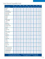
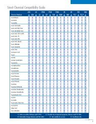
Verlong No Swell Wear Rings - Simrit
Verlong No Swell Wear Rings - Simrit
Verlong No Swell Wear Rings - Simrit
- No tags were found...

Create successful ePaper yourself
Turn your PDF publications into a flip-book with our unique Google optimized e-Paper software.
VERLON <strong>No</strong> <strong>Swell</strong> <strong>Wear</strong> <strong>Rings</strong><br />
Ultra precision<br />
+.001 tolerance<br />
on cross section<br />
NO SWELL -<br />
Lowest friction<br />
Strength to 40,000 PSI<br />
Large range of widths,<br />
cross sections and diameters - metric too<br />
Features & Benefits<br />
ULTRA-PRECISION ADVANTAGES:<br />
Modern hydraulic designs, as well as retrofitted<br />
installations, benefit from the tighter tolerances<br />
that are provided by Verco Ultra-Precision<br />
<strong>Wear</strong> <strong>Rings</strong>.<br />
◆<br />
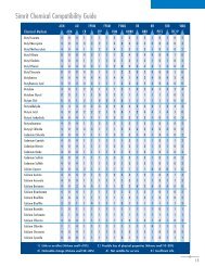
FLUID COMPATIBILITY - Verlon compounds<br />
are compatible with all common hydraulic<br />
oils, water emulsions, water glycol, and<br />
phosphate ester fluids, as well as many<br />
others.<br />
◆<br />
◆<br />
◆<br />
LONG WEARING - The tough properties<br />
inherent in the exclusive Verlon formulations<br />
allow for extremely low wear.<br />
NON-SCORING - Because Verlon <strong>Wear</strong><br />
<strong>Rings</strong> are non-metallic, they totally eliminate<br />
metal-to-metal contact and the consequent<br />
galling and scoring of cylinder bores and<br />
rods.<br />
PORT-PASSING CAPABILITY - The high<br />
strength and stiffness of Verlon <strong>Wear</strong> <strong>Rings</strong><br />
provides special advantages in port-passing<br />
applications.<br />
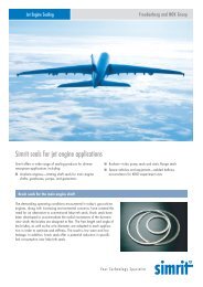
Verco<br />
Ultra-Precision<br />
<strong>Wear</strong> Ring<br />
(very flat)<br />
Conventional<br />
<strong>Wear</strong> <strong>Rings</strong><br />
(dog bone)<br />
Every Ultra-Precision <strong>Wear</strong> Ring is manufactured<br />
under rigid conditions that result in more uniform<br />
tolerances. As a result, Verco Ultra-Precision <strong>Wear</strong><br />
<strong>Rings</strong> feature a cross section tolerance of ±.001".<br />
This means 30% more bearing contact area than<br />
conventionally manufactured wear rings. This<br />
process makes Verco <strong>Wear</strong> <strong>Rings</strong> FLAT.
VERLON Compound Advantages<br />
Series 5000<br />
VN9150 (Standard Grade)<br />
• Virtually zero moisture swell<br />
• +250°F continuous usage<br />
• Highest compression strength<br />
• Self-lubricating<br />
• Ultra-Precision<br />
• Long wearing<br />
Series 6000<br />
VN9100 (Premium Grade)<br />
• Virtually zero moisture swell<br />
• +250°F continuous usage<br />
• High compression strength<br />
• Self-lubricating<br />
• Ultra-Precision<br />
• Extra long wearing<br />
• Low coefficient of friction<br />
Series 5100<br />
VN9154<br />
(More flexible for easy installation)<br />
• Virtually zero moisture swell<br />
• Very low coefficient of friction<br />
• Ultra-Precision<br />
• +250°F continuous<br />
• HTN (high temperature nylon)<br />
• More flexible<br />
Series 7000<br />
VN9500<br />
(Pneumatic & Light-Duty Hydraulic Grade)<br />
• Low moisture swell<br />
• Max. operating temp. 150°F<br />
• Economically priced<br />
• Self-lubricating, long wearing<br />
• Ultra-Precision<br />
• Very low friction<br />
Examples of Applications<br />
Important <strong>No</strong>tes<br />
Earthmoving Forklift Agriculture<br />
Equipment<br />
Equipment<br />
The technical information provided on this<br />
specification sheet is for general guidance only<br />
and values may vary with the specific parameters<br />
and other variables of an application.<br />
For a sealing recommendation specific to your<br />
application, please contact our Engineering<br />
Department.<br />
Truck Injection Molding Std. Hydraulic<br />
Crane Machines Cylinders<br />
Tailgate Lift
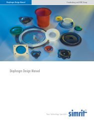
Verlon <strong>Wear</strong> <strong>Rings</strong><br />
Suggested Groove Dimensions<br />
A<br />
B C C B A<br />
D<br />
F<br />
E<br />
D<br />
F<br />
E<br />
In finding the piston mounted wear ring groove<br />
dimensions, begin calculations by subtracting .002*<br />
from the minimum bore (A). Subtract twice the maximum<br />
wear ring thickness (E maximum). The result is<br />
the maximum groove diameter (C maximum). From<br />
this subtract the necessary machining tolerance to<br />
arrive at (C minimum). To C minimum add twice the<br />
minimum wear ring thickness (E minimum) to determine<br />
the minimum installed wear ring OD. From this<br />
figure subtract twice the desired minimum metal-tometal<br />
radial clearance to obtain the maximum metal<br />
piston diameter (B maximum). Groove length (F) is<br />
equal to wear ring axial length D+.010/+.020.<br />
EXAMPLE:<br />
Assume a 3.000/3.003 bore (A). Assume we will<br />
use a wear ring with a thickness of .123/.125 (E), and a<br />
width of 1.000 inch. Presume we are willing to hold<br />
.005 diametral tolerance on machining the pistons.<br />
1. 3.000 minus .002 minus (2 X .125) equals<br />
2.748. This is our maximum wear groove diameter<br />
(C), tolerance is minus (thus, 2.748 + .000-.005).<br />
2. 2.743 plus (2 X .123) equals 2.989. From<br />
this we subtract twice our desired minimum radial<br />
metal-to-metal clearance. Presuming this radial clearance<br />
is desired to be .005, we have 2.989 minus<br />
(2 X .005) equals 2.979, our maximum piston diameter<br />
(B). Applying tolerance minus, we obtain a B of<br />
2.979 + .000 - .005.<br />
3. Groove length (F) becomes (D +.010+.020),<br />
or 1.010/1.020.<br />
4. The piston diameter is typically smaller than<br />
the normal piston diameter recommended in seal catalogs.<br />
Use the smaller diameter. This will result in clearances<br />
behind the seal which would have, in the past,<br />
been considered excessive from a seal extrusion point<br />
of view. <strong>Simrit</strong> has a number of excellent seal types<br />
and/or anti-extrusion devices which are unaffected<br />
by this clearance.<br />
To determine rod wear ring groove dimensions,<br />
begin calculations by adding .002* to the maximum<br />
rod (A maximum). Add twice maximum wear ring<br />
thickness (E maximum). The result is the minimum<br />
groove diameter (C minimum). To this add the necessary<br />
machining tolerances to arrive at C maximum.<br />
From (C maximum) subtract twice the minimum wear<br />
ring thickness (E minimum) to determine the maximum<br />
installed wear ring ID. To this add twice the<br />
desired minimum metal-to-metal radial clearance to<br />
obtain the minimum clearance diameter (B minimum).<br />
Groove length (F) is equal to the wear ring axial length<br />
D +.010/+.020.<br />
EXAMPLE:<br />
Assume a 1.500/1.498 rod (A) Assume we will<br />
use a wear ring with a thickness of .123/.125 (E),<br />
and a width of one-half inch. Presume we are willing<br />
to hold a .003 tolerance in machining our rod gland.<br />
1. 1.500 plus .002 plus (2 X .125) equals 1.752.<br />
This is our minimum wear groove diameter (C), tolerance<br />
is plus (thus, 1.752 + .003 - .000).<br />
2. 1.755 minus (2 X .123) equals 1.509. To<br />
this we add twice our desired minimum radial metalto-metal<br />
clearance. Presuming this radial clearance<br />
is desired to be .005, we have 1.509 plus (2 X .005)<br />
equals 1.519, our minimum rod clearance diameter<br />
(B). Applying tolerance plus, we obtain a B of 1.519<br />
+ .003 - .000.<br />
3. Groove length (F) becomes (D +.010+.020),<br />
or .510/.520.<br />
4. The rod clearance diameter typically is larger<br />
than the normal diameter recommended in seal catalogs.<br />
Use the larger diameter. This will result in clearances<br />
behind the seal which would have, in the past,<br />
been considered excessive form a seal extrusion point<br />
of view. <strong>Simrit</strong> has a number of excellent seal types<br />
and/or anti-extrusion devices which are unaffected<br />
by this clearance.<br />
*This is an installation allowance. Due to thermal expansion of the wear ring or piston, or out-of-round conditions a greater allowances<br />
may be required for smooth operation. This must be determined to fit requirements on each individual application.
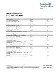
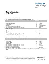
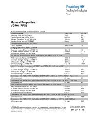
Physical Properties & Compounds<br />
VN9100 VN9150 VN9154 VN9500<br />
Property Units Value Value Value Value<br />
Hardness, Rockwell Points R125 R126 R125 R120<br />
Specific Gravity 1.44 1.50 1.54 1.40<br />
Tensile Strength PSI 28,000 34,000 26,400 8,800<br />
Elongation at Break % 1.40 2.00 2.10 15<br />
Compressive Strength PSI 24,000 40,000 26,700 5,200<br />
Flexural Strength PSI 34,000 50,000 36,900 14,100<br />
Flexural Modulus 1000 PSI 1,900 2,000 1,800 375<br />
Deflection Temp. @ 66 psi °F 540 540 520 277<br />
Water Absorption, 24 hours % 0.17 0.17 0.40 0.21<br />
Reinforcement % 30 40 40 0<br />
Internal Lubricant YES YES YES YES<br />
<strong>Wear</strong> Factor 15 25 11 65<br />
Coefficient of Friction - Static 0.14 0.18 0.16 0.14<br />
Coefficient of Friction - Dynamic 0.18 0.24 0.22 0.21<br />
Thermal Expansion in/in/°F x 10-5 1.3 1.3 1.2 4.7<br />
Generic Compound Name Proprietary Proprietary HTN Acetal<br />
Carbon Filled Glass Filled Glass Filled Co-Polymer<br />
Trade Name Verlon IIIc Verlon III+ Verlon IV Verlin<br />
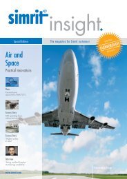
Deflection vs. Compressive Stress<br />
@ Ambient Temperature<br />
Deflection vs. Compressive Stress<br />
@ 200º F Temperature<br />
0.005<br />
0.04<br />
0.0045<br />
0.035<br />
0.004<br />
Deflection in Inch<br />
0.0035<br />
0.003<br />
0.0025<br />
0.002<br />
VN 9154<br />
PHENOLIC<br />
STD Glass Filled Nylon<br />
mineral filled Nylon<br />
VN 9150<br />
Deflection in Inch<br />
0.03<br />
0.025<br />
0.02<br />
0.015<br />
VN 9154<br />
PHENOLIC<br />
STD Glass Filled Nylon<br />
mineral filled Nylon<br />
VN 9150<br />
0.0015<br />
0.001<br />
0.01<br />
0.0005<br />
0.005<br />
0<br />
0 2000 4000 6000 8000 10000 12000 14000<br />
Compressive Stress in PSI<br />
0<br />
0 2000 4000 6000 8000 10000 12000 14000<br />
Compressive Stress in PSI
Who is <strong>Simrit</strong><br />
<strong>Simrit</strong> is the industrial sealing products division of<br />
Freudenberg-NOK that is dedicated to serving industrial<br />
distributors and OEMs. <strong>Simrit</strong> products are manufactured<br />
within the Freudenberg and NOK Group Companies,<br />
known for their world-class quality and reliability.<br />
<strong>Simrit</strong>’s manufacturing and design expertise, coupled<br />
with exceptional customer service and field engineering<br />
support, enables us to provide our customers superior<br />
sealing components and total system sealing solutions<br />
that exceed their expectations.<br />
<strong>Simrit</strong> - Your Technology Specialist.<br />
Fluid Power Business Unit<br />
3600 West Milwaukee<br />
Spencer, IA 51301<br />
Phone: 712.262.4867 Fax: 712.262.8160 www.simrit.com<br />
<strong>No</strong>rth American Headquarters<br />
47690 East Anchor Ct<br />
Plymouth, MI 48170<br />
Phone: 1.866.2SIMRIT<br />
Fax: 734.354.5500<br />
0202NS5.5M<br />
O-Ring Business Unit<br />
25151 Arctic Ocean Drive<br />
Lake Forest, CA 92630<br />
Phone: 949.598.8155<br />
Fax: 949.598.8151<br />
Radial Shaft Seal Business Unit<br />
11617 State Route 13<br />
Milan, OH 44846<br />
Phone: 419.499.2502<br />
Fax: 419.499.6111