Manual test kit TK 99D - Watts waterbeveiliging
Manual test kit TK 99D - Watts waterbeveiliging
Manual test kit TK 99D - Watts waterbeveiliging
- No tags were found...

You also want an ePaper? Increase the reach of your titles
YUMPU automatically turns print PDFs into web optimized ePapers that Google loves.
<strong>Manual</strong> <strong>test</strong> <strong>kit</strong><br />
<strong>TK</strong> <strong>99D</strong><br />
The <strong>TK</strong> <strong>99D</strong> <strong>test</strong> <strong>kit</strong> consists of a digital<br />
differential pressure gauge with connecting<br />
hoses and adapters. It enables measuring<br />
both the pre-pressure and the differential<br />
pressures. The <strong>TK</strong> <strong>99D</strong> allows you to <strong>test</strong><br />
the backflow prevention devices BA 009,<br />
BA 909, BA BS and BA BM quickly and<br />
easily. This manual describes how to<br />
connect the digital <strong>test</strong> <strong>kit</strong> and how to<br />
perform the various <strong>test</strong>s.
<strong>Manual</strong> Backflow Preventer Test Kit <strong>TK</strong> <strong>99D</strong><br />
Testing the BA backflow preventer with <strong>test</strong> <strong>kit</strong> <strong>TK</strong><strong>99D</strong><br />
2<br />
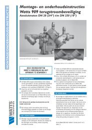
Description of the <strong>test</strong> <strong>kit</strong><br />
Before starting the <strong>test</strong>:<br />
high pressure hose (red)<br />
low pressure hose (blue)<br />
• Check if the BA device is not<br />
damaged, or if anything has been<br />
changed on the device so that it no<br />
longer complies with the EN1717.<br />
A B C<br />
bypass (yellow)<br />
<strong>test</strong> valves<br />
1 2 3<br />
shut off valve<br />
shut off valve<br />
4 5<br />
• Check the safety class of the<br />
“dangerous” device behind the BA.<br />
• Check if the device has been placed<br />
as a unit; this means with a strainer<br />
and 2 valves. If any valves are<br />
missing, the device cannot be <strong>test</strong>ed.<br />
Names on the <strong>test</strong><strong>kit</strong> <strong>TK</strong> <strong>99D</strong><br />
A-Gage = upstream pressure<br />
A-B DIFF = pressure difference<br />
Figure 1: BA BM DN15 up to DN50<br />
Verify:<br />
- if the supply of drinking-water may be interrupted.<br />
- when the device was last <strong>test</strong>ed.<br />
Otherwise, check for contamination in the pipe or the<br />
<strong>test</strong> valves. This is to prevent having to repair the <strong>kit</strong>.<br />
De-aerate the BA device if you have not already<br />
done so<br />
1. Start by carefully opening <strong>test</strong> valve no. 3, so that the<br />
water starts to run slowly. This will cause the flow in<br />
the device.<br />
2. Carefully open <strong>test</strong> valve no 1 until a steady flow of<br />
water is released and then carefully close the valve.<br />
3. Next, do the same with <strong>test</strong> valve no. 2.<br />
4. Then, close <strong>test</strong> valve no. 3<br />
(With the BA 909 flanged: also de-aerate the relief valve<br />
through the shut off valve on top of the relief part).<br />
Connecting the <strong>test</strong> <strong>kit</strong><br />
1. Connect the hoses to the <strong>test</strong> <strong>kit</strong> with the colours<br />
according to the drawing.<br />
2. Attach the adapters to the <strong>test</strong> valves of the<br />
BA device.<br />
3. Attach the red hose to <strong>test</strong> valve no. 1 of the<br />
BA device and ensure a leak-tight connection.<br />
4. Next, attach the blue hose to <strong>test</strong> valve no. 2 of<br />
the BA device.<br />
Do not yet connect the yellow hose to the BA device.<br />
The BA device is now de-aerated.<br />
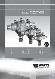
2 3<br />
1<br />
1 2 3<br />
1<br />
BA 909 DN65 up to DN250<br />
1<br />
2<br />
3<br />
BA 009 DN15 up to DN50<br />
1<br />
2<br />
3<br />
BA 909 DN20 up to DN50<br />
BA 009 DN65 & DN80<br />
Figure 2: Position of the <strong>test</strong> valves
<strong>Manual</strong> Backflow Preventer Test Kit <strong>TK</strong> <strong>99D</strong><br />
De-aeration of the Test <strong>kit</strong><br />
Initial situation: the needle valves are closed.<br />
Test valves 1, 2 and 3 are closed. Shut off valve 4 is<br />
open and shut off valve 5 is closed.<br />
1. Slowly open <strong>test</strong> valves 1 and 2.<br />
2. Open needle valve C.<br />
3. Open needle valve A to allow the water with air to flow<br />
away via the red hose through the <strong>test</strong> <strong>kit</strong> and the yellow<br />
by-pass hose. Close needle valve A on the <strong>test</strong> <strong>kit</strong>.<br />
4. Open needle valve B, ensuring that the water with air<br />
can flow away via the blue hose through the <strong>test</strong> <strong>kit</strong><br />
and the yellow hose.<br />
5. Close needle valve C slowly until only a trickle of<br />
water runs from the yellow hose.<br />
6. Open <strong>test</strong> valve 3 until it slightly flows over and<br />
connect the yellow hose to <strong>test</strong> valve 3, while water<br />
flows from both, and open the <strong>test</strong> valve completely<br />
(so-called wet connection preventing air being trapped<br />
in the <strong>test</strong> <strong>kit</strong>).<br />
7. Slightly open the connection to <strong>test</strong> valve 2 and then<br />
close it again. This is to compensate for unwanted<br />
impression of the seat.<br />
8. Close needle valves B and C.<br />
9. Switch on the <strong>test</strong> <strong>kit</strong>.<br />
The <strong>test</strong> <strong>kit</strong> is now ready to perform the <strong>test</strong>.<br />
1. Testing shut off valve 5<br />
Aim: to <strong>test</strong> the leak-tightness of valve 5. It must be<br />
fully closed in order to perform <strong>test</strong>s no. 2, 3, 4 and 5<br />
accurately.<br />
Initial situation: The needle valves are closed. Test<br />
valves 1, 2 and 3 are open. Shut off valve 4 is open and<br />
shut off valve 5 is closed.<br />
1. Close <strong>test</strong> valve 1.<br />
2. Open needle valves A and C (Value A-Gage and A-B<br />
DIFF will slightly drop).<br />
3. Open a tap behind shut off valve 5, allowing the water<br />
to flow downstream.<br />
If the measured difference in pressure A-B DIFF<br />
remains constant, this means that shut off valve 5<br />
closes tightly. If the difference in pressure A-B DIFF<br />
drops, this means that the water (pressure A) in the<br />
red hose can flow away via the yellow hose through a<br />
leaking shut off valve 5.<br />
2. Testing the leak-tightness of the<br />
1 st non-return valve<br />
Aim: to check whether the 1st check valve is closed<br />
under all differential pressures.<br />
Initial situation: The needle valves are closed. Test<br />
valves 1 and 2 are open and 3 is closed. Shut off valve<br />
4 is open and shut off valve 5 is closed.<br />
If the indicated pressure A-Gage and differential<br />
pressure A-B DIFF remain constant, we may assume<br />
that the 1 st check valve is leak-tight.<br />
If the differential pressure on the 1 st non-return valve<br />
is constant but low (< 4 kPa), the 1 st check valve or the<br />
relief valve may be slightly contaminated. In the event of<br />
fluctuation in the upstream pressure, this may result in a<br />
regular discharge of the device.<br />
3. Testing the relief valve<br />
Aim: To check if the relief valve opens when the<br />
pressure in the intermediate chamber is still at least<br />
14 kPa lower than the upstream pressure.<br />
Initial situation: The needles valves are closed. Test<br />
valves 1 and 2 are open and 3 is closed. Shut off valve<br />
4 is open and shut off valve 5 is closed.<br />
1. Slowly open needle valve A.<br />
2. Open needle valve B no more than ¼ turn. Allow the<br />
differential pressure A-B DIFF to slowly drop until the<br />
water starts to leak from the relief opening.<br />
3. As soon as the water starts to leak, check the gauge<br />
and note down the value. This is the differential<br />
pressure at which the relief valve opens. This should<br />
be at least 14 kPa.<br />
4. Close the needle valves on the <strong>test</strong> <strong>kit</strong>.<br />
4. Checking the leak-tightness of the 2 nd<br />
check valve<br />
Aim: To check whether this non-return valve fully closes<br />
under all differential pressures.<br />
Initial situation: The needle valves are closed. Test<br />
valves 1, 2 and 3 are open. Shut off valve 4 is open and<br />
shut off valve 5 is closed.<br />
1. Close <strong>test</strong> valve 1.<br />
2. Open needle valves A and C.<br />
If the values with A-Gage and A-B DIFF remain<br />
constant, the 2 nd check valve is leak-tight. If A-Gage<br />
and A-B DIFF drop, this means that the water from the<br />
red hose will flow back to the intermediate chamber<br />
via the yellow hose and the leaking 2 nd check valve.<br />
3. Close the needle valves on the <strong>test</strong> <strong>kit</strong>.<br />
5. Measuring the differential pressure on the<br />
2 nd non-return valve (=optional)<br />
Initial situation: The needle valves are closed. Shut off<br />
valve 4 is open and shut off valve 5 is closed.<br />
1. Close all the <strong>test</strong> valves on the BA device and<br />
disconnect all hoses.<br />
2. Connect the red hose to <strong>test</strong> valve 2 of the BA device.<br />
3. Connect the blue hose to <strong>test</strong> valve 3.<br />
4. Slowly open <strong>test</strong> valves 2 and 3.<br />
5. Open needle valve C.<br />
6. Open needle valve A to allow the water with air to<br />
flow away via the red hose through the <strong>test</strong> <strong>kit</strong> and the<br />
yellow by-pass hose. Connect needle valve A to the <strong>kit</strong>.<br />
7. Open needle valve B to allow the water with air to flow<br />
away via the blue hose through the <strong>test</strong> <strong>kit</strong> and the<br />
yellow hose.<br />
8. Close needle valve B.<br />
9. Check the differential pressure value A-B DIFF and note<br />
down the differential pressure over the 2 nd check valve.<br />
The difference in pressure over the 2 nd check valve<br />
with a BA 009/909 is +/- 2 – 2.5 kPa. The difference in<br />
pressure with a BA BM is +/- 0.05 – 0.1 kPa.<br />
Finishing the <strong>test</strong>ing of the BA device<br />
The BA device has now been <strong>test</strong>ed.<br />
- Close all <strong>test</strong> valves on the BA device.<br />
- Open all needle valves on the <strong>test</strong> <strong>kit</strong>.<br />
- Disconnect the hoses of the BA device and discharge<br />
the water from the <strong>test</strong> <strong>kit</strong> to prevent possible freezing<br />
in the winter.<br />
- Do not forget to remove the adapters.<br />
- Open shut off valve 5 to return the flow in the system.<br />
3
Product range <strong>Watts</strong> Industries<br />
- System Disconnectors<br />
- Backflow Protection Devices<br />
- Check Valves<br />
- Safety Units<br />
- Safety Relief Valves<br />
- Pressure Reducing Valves<br />
- Automatic Control Valves<br />
- Butterfly Valves<br />
- Shut-Off Valves<br />
- Measuring Gauges<br />
- Temperature Control<br />
- Expansion Vessels<br />
- Process Switches<br />
- Fuel Products<br />
- Gas Products<br />
- Electronic Controls<br />
- Installation Protection Products<br />
- Radiator Valves<br />
- System Products<br />
- Manifolds and Fittings<br />
50A-0004-NL-UK-13/09<br />
<strong>Watts</strong> Industries Netherlands B.V.<br />
Kollergang 14, 6961 LZ Eerbeek, The Netherlands<br />
Phone +31 313 673 750 - Fax +31 313 652 073<br />
E-mail info@wattsindustries.nl<br />
Sites www.wattsindustries.com - www.waterprotection.com