KAPv2.2 Kestrel Autopilot v2.2 Data Sheet - Unmanned Aircraft ...
KAPv2.2 Kestrel Autopilot v2.2 Data Sheet - Unmanned Aircraft ...
KAPv2.2 Kestrel Autopilot v2.2 Data Sheet - Unmanned Aircraft ...

Create successful ePaper yourself
Turn your PDF publications into a flip-book with our unique Google optimized e-Paper software.
<strong>KAP<strong>v2.2</strong></strong><br />
<strong>Kestrel</strong> <strong>Autopilot</strong> <strong>v2.2</strong><br />
<strong>Data</strong> <strong>Sheet</strong><br />
FEATURES<br />
• 16.7 grams<br />
• Fits within 2.73 in 2 Area & 1.29 in 3 Volume<br />
• 3-Axis Angular Rate Measurement<br />
• 3-Axis Acceleration Measurement<br />
• 2-Axis Magnetometer<br />
• Absolute and Differential Pressure Sensors<br />
• 20 Point Sensor Temperature Compensation<br />
• External Power @ 3.3V & 5V, 500mA<br />
• Efficient Switching Power Regulation<br />
• Battery Voltage and Current Monitor<br />
• 29MHz Processor w/ 512K RAM & FLASH<br />
• 4 Serial Ports (Std.,SPI,I 2 C) w/ Digital Clock or I/O<br />
• 4 Standard Servo Ports<br />
• 12 Digital I/O (6 bi-directional, 3 input, 3 output)<br />
• 3 Analog Inputs @ 12bit resolution<br />
• Optional Piggy-Back Modem Header<br />
• Wind Estimation<br />
• Multiple Failsafes<br />
• Multi-UAV Support<br />
• Convoy Following Support<br />
• Auto-trim<br />
APPLICATIONS<br />
• Autonomous GPS navigation of UAVs and MAVs<br />
• Inertial Measure Unit<br />
• Slave Processing Unit<br />
• Payload Communication & Control Support<br />
• <strong>Data</strong> Logger<br />
• Multiple vehicle operations<br />
DESCRIPTION<br />
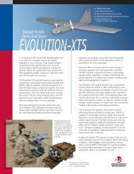
The <strong>Kestrel</strong> TM <strong>Autopilot</strong> <strong>v2.2</strong> is designed for autonomous flight<br />
control of small UAVs and MAVs. At 16.7 grams, it is the<br />
smallest (2” x 1.37” x .47”) and lightest full featured autopilot<br />
on the market - ideal for all surveillance and reconnaissance<br />
applications. The Virtual Cockpit ground control software<br />
makes “click N’ fly” operation easy while providing powerful<br />
mission planning, monitoring, and in-flight adjustment. New<br />
“piggy-back” header allows the modem to be plugged directly<br />
into the autopilot. The magnetometer can either be on board<br />
the autopilot or off board depending on users setup<br />
requirements.<br />
Its IMU is composed of 3-axis rate gyros and accelerometers.<br />
Absolute and differential pressure sensors provide barometric<br />
pressure and aircraft air speed. 3 temperature sensors<br />
combined with a 20 point temperature compensation<br />
algorithm reduce sensor drift improving aircraft state<br />
measurement and estimation.<br />
Switching power regulation achieves high efficiency, drawing<br />
only 0.77 Watts while running cooler and consuming less<br />
power (less than half of KAPv1.45). External payloads can be<br />
powered at 3.3V and 5V, 500mA each. Battery voltage and<br />
current monitoring provides battery life information.<br />
4 serial ports allow for support of payload intercommunication<br />
and control. Serial interfaces allow for the<br />
use of standard off-the-shelf digital modems and GPS units.<br />
The GPS can be placed in a location independent of the<br />
autopilot.<br />
<strong>Kestrel</strong> and Virtual Cockpit are trademarks of Procerus Technologies.<br />
www.procerusuav.com 801-224-5713<br />
1
<strong>KAP<strong>v2.2</strong></strong><br />
ABSOLUTE MAXIMUM RATINGS<br />
Input Supply Voltage ..............................................-0.3V to 18V<br />
Payload Current........................................500mV @ 3.3V & 5V<br />
Operating Temperature Range ...........................-40ºC to 85ºC<br />
Storage Temperature Range.............................-40ºC to 125ºC<br />
Maximum Absolute Pressure........................................400 kPa<br />
Maximum Differential Pressure ....................................... 75kPa<br />
Humidity .........................................5% to 95%, no condensing<br />
Acceleration .................................................................... ±200 g<br />
Stresses above those listed under the Absolute Maximum Ratings<br />
may cause permanent damage to the autopilot. This is a stress<br />
rating only; functional operation of the device at these or any other<br />
conditions above those indicated in the operational section of this<br />
specification are not implied. Exposure to absolute maximum rating<br />
conditions for extended periods may affect device reliability.<br />
OPERATING CHARACTERISTICS<br />
Parameter Conditions Min Typ Max Units<br />
INPUT VOLTAGE (PWR)<br />
Operating Input Voltage Range<br />
Quiescent Supply Current<br />
6.0<br />
80<br />
15.5 V<br />
mA<br />
Payload POWER (Each Supply)<br />
3.3V Source<br />
5V Source<br />
Supply Current<br />
Accuracy<br />
Noise<br />
3.3<br />
5.0<br />
±0.5<br />
10µV RMS /V•V OUT<br />
≈2.0<br />
500<br />
±2<br />
W<br />
V<br />
V<br />
mA<br />
%<br />
µV RMS<br />
Payload Serial & I/O<br />
Logic High<br />
Logic Low<br />
Current (Sink & Source)<br />
Rate Gyros<br />
Dynamic Range<br />
Frequency Response (3dB Bandwidth)<br />
Resonant Frequency<br />
Accelerometers<br />
Dynamic Range<br />
Frequency Response (3dB Bandwidth)<br />
Resonant Frequency<br />
Attitude Estimation Error: Roll and Pitch<br />
Level Flight<br />
During Turns<br />
Differential Pressure: <strong>KAP<strong>v2.2</strong></strong>0, <strong>KAP<strong>v2.2</strong></strong>1<br />
Range<br />
Resolution<br />
Differential Pressure: <strong>KAP<strong>v2.2</strong></strong>2<br />
Range<br />
Resolution<br />
Absolute Pressure: <strong>KAP<strong>v2.2</strong></strong>0, <strong>KAP<strong>v2.2</strong></strong>1<br />
Range<br />
Resolution<br />
Absolute Pressure: <strong>KAP<strong>v2.2</strong></strong>2<br />
Range<br />
Resolution<br />
Airspeed: <strong>KAP<strong>v2.2</strong></strong>0, <strong>KAP<strong>v2.2</strong></strong>1<br />
Range<br />
Resolution<br />
Airspeed: <strong>KAP<strong>v2.2</strong></strong>2<br />
Range<br />
Resolution<br />
Altitude: <strong>KAP<strong>v2.2</strong></strong>0, <strong>KAP<strong>v2.2</strong></strong>1<br />
Range<br />
Resolution<br />
Altitude: <strong>KAP<strong>v2.2</strong></strong>2<br />
Range<br />
Resolution<br />
Dimensions<br />
Accuracy<br />
Weight<br />
Accuracy<br />
T A = 25°C, V S = 5 V, Bandwidth = 9Hz<br />
T A = 25°C, V DD = 5 V<br />
T A = 25°C, V S = 5 V<br />
T A = 25°C, V S = 5 V<br />
T A = 25°C, V S = 5 V<br />
T A = 25°C, V S = 5 V<br />
T A = 25°C, V S = 5 V<br />
13 m/s (29 mph)<br />
T A = 25°C, V S = 5 V<br />
13 m/s (29 mph)<br />
T A = 25°C, V S = 5 V<br />
Standard atmospheric pressure<br />
T A = 25°C, V S = 5 V<br />
Standard atmospheric pressure<br />
2.3<br />
-0.25<br />
-1.3<br />
101.5<br />
110<br />
0<br />
0<br />
-13.7 (-45)<br />
-698 (-2,290)<br />
9<br />
14<br />
22<br />
10<br />
0.000166<br />
0.000545<br />
0.00115<br />
0.00248<br />
0.0076 (0.017)<br />
0.025 (0.056)<br />
0.116 (0.379)<br />
0.249 (0.818)<br />
2.073 x 1.375<br />
±0.5<br />
16.65<br />
±4<br />
0.4<br />
6.8<br />
±300<br />
±10<br />
5<br />
10<br />
4.7<br />
15.8<br />
66.5<br />
41<br />
70 (156)<br />
130 (290)<br />
3414 (11,200)<br />
7010 (23,000)<br />
V<br />
V<br />
mA<br />
°/s<br />
Hz<br />
kHz<br />
g<br />
Hz<br />
kHz<br />
°<br />
°<br />
kPa<br />
kPa<br />
kPa<br />
kPa<br />
kPa<br />
kPa<br />
kPa<br />
kPa<br />
m/s (mph)<br />
m/s (mph)<br />
m/s (mph)<br />
m/s (mph)<br />
m (ft)<br />
m (ft)<br />
m (ft)<br />
m (ft)<br />
inches<br />
%<br />
grams<br />
%<br />
2
<strong>KAP<strong>v2.2</strong></strong><br />
PORT FUNCTIONS<br />
The following tables describe the general pin assignments for each port type.<br />
Power Port<br />
Pin Description<br />
1 GND<br />
2 PWR (6V – 18V)<br />
3 Current Monitor<br />
Servo Ports<br />
Pin Description<br />
1 PWR<br />
2 GND<br />
3 Signal<br />
Optional ADC Port<br />
Pin Description<br />
1 GND<br />
2 PWR (3.3V or 5V)<br />
3 Ch 1<br />
4 Ch 2<br />
5 Ch 3<br />
Serial Ports<br />
Pin Description<br />
1 GND<br />
2 PWR (3.3V or 5V)<br />
3 <strong>Autopilot</strong> TX<br />
4 <strong>Autopilot</strong> RX<br />
5 CMD or CLK<br />
Power Port: This port supplies the autopilot power and is<br />
typically connected directly to the autopilot or aircraft main<br />
battery. The GND and PWR pins connect to the negative and<br />
positive battery terminal respectively. The Current Monitor pin<br />
is used to detect current draw of the main battery by<br />
measuring the voltage drop across a 0.01Ω resistor in series<br />
with the battery. This resistor’s power rating should be as<br />
follows:<br />
RESISTOR POWER > (MAX MOTOR CURRENT) 2 x 0.01 (WATTS)<br />
Typical Current Monitor Circuit:<br />
TO BATTERY<br />
− TERMINAL<br />
TO CURRENT MONITOR PIN<br />
TO SPEED CONTROL<br />
− TERMINAL<br />
The MODEM port is optional if the modem is not plugged into<br />
the modem “piggy-back” header. For each serial port, the<br />
autopilot TX and RX lines are found on pins 3 and 4<br />
respectively. All serial ports operate at TTL levels (0V to<br />
3.3V) and can be configured for standard serial, SPI, or I 2 C<br />
communication. Pin 5 on all serial ports serves as a digital<br />
I/O. Pins 2 and 3 can be used as digital I/O if not being used<br />
for serial communication. Table 1 shows the pin<br />
assignments (connections to Rabbit 3000 processor) of all<br />
serial ports.<br />
Pin SerA SerE GPS Modem<br />
1 GND GND GND GND<br />
2 PWR (3.3V or<br />
5V)<br />
PWR (3.3V or<br />
5V)<br />
PWR (3.3V or<br />
5V)<br />
PWR (3.3V or<br />
5V)<br />
3 TxA (PC6) TxE (PG6) TxD (PC0) TxF (PG2)<br />
4 RxA (PC7) RxE (PG7) RxD (PC1) RxF (PG3)<br />
5 ClkA (PB1) ClkE (PG5) ClkD (PF0) TClkF (PG0)<br />
Table 1 - Serial Port Pin Descriptions<br />
0.01 ohm<br />
Optional ADC Ports: Three analog inputs (pins 3-5) on the<br />
Optional ADC port allow users to measure 0.01V to 3.29V.<br />
Filtered analog 5V is available on pin 2. This pin supplies the<br />
autopilot analog sensors so take caution not to introduce<br />
noise on this pin.<br />
Serial & I/O Ports: There are 4 serial ports that double as I/O<br />
ports. Serial E and Serial A allow users to interface with<br />
payload needs. The GPS port is dedicated for the GPS unit.<br />
Servo Ports: These ports are configurable for different<br />
aircraft types. Servo connections for standard configurations<br />
are as follows:<br />
V-Tail Configuration<br />
Port Channel<br />
1 Right V-Tail<br />
2 Left V-Tail<br />
3 Throttle<br />
Elevon Configuration<br />
Port Channel<br />
1 Left Elevon<br />
2 Right Elevon<br />
3 Throttle<br />
3
<strong>KAP<strong>v2.2</strong></strong><br />
KESTREL AUTOPILOT<br />
The autopilot is the heart of the <strong>Kestrel</strong> system. It is powered by an 8-bit 29 MHz processor. The autopilot board contains a suite of<br />
sensors used by the autopilot software to measure and estimate the states of the aircraft. The autopilot interfaces directly to the<br />
digital communication link which enables it to send real-time status telemetry to the ground station and receive commands in-flight.<br />
The GPS plugs into the autopilot board (optional) and provides inertial navigation information to the autopilot. It also has several<br />
additional interface ports to support payloads. The autopilot controls the aircraft through four standard RC hobby servos. If more<br />
servos are needed, a servo extender board can be used. Figure 1 shows the <strong>Kestrel</strong> autopilot with modem attached.<br />
6-DOF<br />
IMU<br />
Airspeed<br />
Port<br />
Altitude<br />
Port<br />
GPS port<br />
Programming<br />
and I/O ports<br />
Servo Ports<br />
<strong>Autopilot</strong> Power and<br />
Current Measure Port<br />
Modem<br />
Analog input port<br />
Figure 1 - <strong>Kestrel</strong> 2.2 autopilot with Aerocomm AC4490 modem attached.<br />
Z<br />
Y<br />
X<br />
RATE GYROS<br />
3<br />
Z<br />
Y<br />
X<br />
ACCELEROMETERS<br />
3<br />
ABSOLUTE<br />
PRESSURE<br />
DIFFERENTIAL<br />
PRESSURE<br />
Z<br />
Y<br />
X<br />
RATE GYROS<br />
TEMERATURE<br />
3<br />
ADC<br />
ADC<br />
SPI BUSS<br />
SPI BUSS<br />
PROCESSOR<br />
4<br />
4<br />
SERVO<br />
PORTS<br />
SERIAL<br />
PORTS<br />
OPTIAL ADC<br />
PORT<br />
3<br />
RCM3400<br />
PWR<br />
PORT<br />
SWITCHING REG.<br />
CIRCUIT<br />
+5V<br />
+3.3V<br />
Figure 2 - <strong>Kestrel</strong> 2.x block diagram.<br />
4
<strong>KAP<strong>v2.2</strong></strong><br />
Port & LED Locations<br />
Top View<br />
<strong>Aircraft</strong> Front<br />
Figure 3 - Port and LED locations on the <strong>Kestrel</strong> 2.x autopilot. (2” x 1.37” x .47”)<br />
Jumper and Header Locations<br />
Top View<br />
<strong>Aircraft</strong> Front<br />
Figure 4 - Jumper and header locations on the <strong>Kestrel</strong> 2.x autopilot.<br />
5
<strong>KAP<strong>v2.2</strong></strong><br />
<strong>Kestrel</strong> <strong>Autopilot</strong> <strong>v2.2</strong><br />
Sensors and Attitude Estimation<br />
- Increased resolution on all sensors (8 x increase)<br />
- Acceleration measurements down to 1 mg<br />
- Roll and pitch estimation corrected for coriolis forces (10 - 25% improved roll and pitch estimates)<br />
- 2axis - magnetometer support - compass heading used to calibrate heading gyro on ground and in low ground speed situations.<br />
- Quicker sensor calibration and improved navigation – improved path following and altitude hold<br />
- Assist human pilot in speed and altitude mode (display on video)<br />
3-Sensor Temperature Compensation<br />
- 3 temperature sensors combined with 20 point temperature compensation algorithm significantly reduces sensor drift due to<br />
temperature changes. This reduces the need for the user to re-calibrate gyros and pressure sensors, aiding in sea or mobile<br />
operations.<br />
Wind estimation<br />
- Real-time wind estimation algorithm relies on airspeed and GPS - continually updating estimate with latest wind data. Good to<br />
5% on wind speed and 2% on wind heading.<br />
Auto-trim<br />
The autopilot can automatically fine tune UAV trim characteristics in the air. Trim values are then saved on the autopilot.<br />
Switching Voltage Regulation<br />
- The nominal regulator temperature remains constant over a broad range of input voltages. The maximum voltage input can be<br />
up to 18 volts. (v2.x runs 50% cooler and draws 50% of the power compared to v1.45)<br />
10g Accelerometers<br />
- 10g accelerometers now used vs 2g to better address vibration susceptibility in certain airframe configurations. The <strong>Kestrel</strong> can<br />
also be configured with 2g sensors if desired.<br />
Mode support - single click autopilot configurations<br />
- Rate mode - rates only, activated by switch on RC box<br />
- Speed mode - aircraft holds airspeed using pitch, (roll, airspeed, and throttle commands on ground station)<br />
- Altitude mode - aircraft holds altitude (roll, airspeed, and altitude commands from on ground station<br />
- Nav mode - aircraft navigates to standard and loiter waypoints<br />
- Home mode - aircraft flies home and loiters<br />
- Loiter now mode - aircraft loiters at current position<br />
- Take off mode - aircraft uses preset commands to take off - automatically transitions to Nav mode at pre-set altitude<br />
- Land mode - aircraft flies to landing point on map and lands<br />
- Rally mode - aircraft flies to Rally point<br />
Multiple user-configurable failsafes<br />
- Loss of communications<br />
- Loss of GPS lock<br />
- Low Battery and Critical Battery<br />
- Rate Mode<br />
6