Eppendorf Femtojet Manual - Duke University Light Microscopy ...
Eppendorf Femtojet Manual - Duke University Light Microscopy ...
Eppendorf Femtojet Manual - Duke University Light Microscopy ...

Create successful ePaper yourself
Turn your PDF publications into a flip-book with our unique Google optimized e-Paper software.
FemtoJet ®<br />
Operating <strong>Manual</strong><br />
<strong>Eppendorf</strong> AG<br />
22331 Hamburg · Germany<br />
Phone: +49 40-5 38 01-0<br />
Fax: +49 40-5 38 01-556<br />
e-mail: eppendorf@eppendorf.com<br />
Internet: www.eppendorf.com<br />
Application Hotline:<br />
Phone: +49 180-3 66 67 89<br />
e-mail:<br />
application-hotline@eppendorf.de<br />
Brinkmann Instruments, Inc.<br />
One Cantiague Road,<br />
P.O. Box 1019<br />
Westbury, New York 11590-0207<br />
(USA)<br />
Phone: 800-645-3050<br />
Fax: 516-334-7506<br />
e-mail: info@brinkmann.com<br />
Internet: www.brinkmann.com<br />
Printed in Germany<br />
eppendorf ® is a registered trademark
Contents<br />
1 Safety precautions and application. . . . . . . . . . . . . . . . . . . 3<br />
2 Device description. . . . . . . . . . . . . . . . . . . . . . . . . . . . . . . . . 5<br />
2.1 Overview . . . . . . . . . . . . . . . . . . . . . . . . . . . . . . . . . . . . . . . . . 6<br />
2.2 Short description . . . . . . . . . . . . . . . . . . . . . . . . . . . . . . . . . . . 8<br />
2.3 Startup. . . . . . . . . . . . . . . . . . . . . . . . . . . . . . . . . . . . . . . . . . 10<br />
3 Mode of operation . . . . . . . . . . . . . . . . . . . . . . . . . . . . . . . . 12<br />
3.1 Display, variable regulators and keypad . . . . . . . . . . . . . . . . 12<br />
3.1.1 Setting the injection parameters . . . . . . . . . . . . . . . . . . . . . . 12<br />
3.1.2 Variable regulators. . . . . . . . . . . . . . . . . . . . . . . . . . . . . . . . . 13<br />
3.1.3 Keypad. . . . . . . . . . . . . . . . . . . . . . . . . . . . . . . . . . . . . . . . . . 14<br />
3.2 Hand control / foot control . . . . . . . . . . . . . . . . . . . . . . . . . . . 17<br />
3.3 Connecting the capillary holder . . . . . . . . . . . . . . . . . . . . . . . 18<br />
3.4 Information on working practices. . . . . . . . . . . . . . . . . . . . . . 20<br />
3.4.1 Compensation pressure p c . . . . . . . . . . . . . . . . . . . . . . . . . . 21<br />
3.4.2 Injection pressure p i . . . . . . . . . . . . . . . . . . . . . . . . . . . . . . . . 21<br />
3.4.3 Injection time t i . . . . . . . . . . . . . . . . . . . . . . . . . . . . . . . . . . . 22<br />
3.4.4 Clean function . . . . . . . . . . . . . . . . . . . . . . . . . . . . . . . . . . . . 22<br />
3.4.5 <strong>Manual</strong> or automatic injection . . . . . . . . . . . . . . . . . . . . . . . . 23<br />
3.4.6 Constant pressure/constant working pressure . . . . . . . . . . . 23<br />
3.4.7 General note . . . . . . . . . . . . . . . . . . . . . . . . . . . . . . . . . . . . . 23<br />
3.5 The first injection . . . . . . . . . . . . . . . . . . . . . . . . . . . . . . . . . . 24<br />
3.6 Connecting an <strong>Eppendorf</strong> Micromanipulator . . . . . . . . . . . . . 25<br />
3.7 Functions . . . . . . . . . . . . . . . . . . . . . . . . . . . . . . . . . . . . . . . . 26<br />
3.7.1 Changing the capillaries . . . . . . . . . . . . . . . . . . . . . . . . . . . . 26<br />
3.7.2 Setting the pressure unit . . . . . . . . . . . . . . . . . . . . . . . . . . . . 26<br />
3.7.3 Switching on/off the loudspeaker. . . . . . . . . . . . . . . . . . . . . . 27<br />
3.7.4 Switching on/off the background illumination of the display . 27<br />
3.7.5 Constant pressure . . . . . . . . . . . . . . . . . . . . . . . . . . . . . . . . . 27<br />
3.7.6 Dewatering the pressure accumulator. . . . . . . . . . . . . . . . . . 28<br />
4 Care and maintenance . . . . . . . . . . . . . . . . . . . . . . . . . . . . 29<br />
4.1 Cleaning . . . . . . . . . . . . . . . . . . . . . . . . . . . . . . . . . . . . . . . . 29<br />
4.2 Disinfection . . . . . . . . . . . . . . . . . . . . . . . . . . . . . . . . . . . . . . 29<br />
4.3 Maintenance . . . . . . . . . . . . . . . . . . . . . . . . . . . . . . . . . . . . . 29<br />
No part of this publication may be reproduced without the prior permission of the copyright owner.<br />
Copyright © 2000 by <strong>Eppendorf</strong> AG, Hamburg<br />
B 5247 900.011-03/0201
Contents<br />
5 Troubleshooting . . . . . . . . . . . . . . . . . . . . . . . . . . . . . . . . . 30<br />
5.1 Potential errors . . . . . . . . . . . . . . . . . . . . . . . . . . . . . . . . . . . 30<br />
5.1.1 Self-test . . . . . . . . . . . . . . . . . . . . . . . . . . . . . . . . . . . . . . . . . 30<br />
5.2 Warnings . . . . . . . . . . . . . . . . . . . . . . . . . . . . . . . . . . . . . . . . 32<br />
5.3 Error messages. . . . . . . . . . . . . . . . . . . . . . . . . . . . . . . . . . . 33<br />
6 Technical data . . . . . . . . . . . . . . . . . . . . . . . . . . . . . . . . . . . 40<br />
7 Ordering information . . . . . . . . . . . . . . . . . . . . . . . . . . . . . 41<br />
8 Index. . . . . . . . . . . . . . . . . . . . . . . . . . . . . . . . . . . . . . . . . . . 43<br />
Appendix A . . . . . . . . . . . . . . . . . . . . . . . . . . . . . . . . . . . . . . . . . . . . 45<br />
Operation via a computer. . . . . . . . . . . . . . . . . . . . . . . . . . 45<br />
A.1 Description of interface . . . . . . . . . . . . . . . . . . . . . . . . . . . . . 45<br />
A.2 Commands and queries . . . . . . . . . . . . . . . . . . . . . . . . . . . . 45<br />
EC Conformity Declaration<br />
2
1 Safety precautions and application<br />
●<br />
Observe operating instructions!<br />
●<br />
Before plugging in the device, please compare your voltage<br />
requirements with the specifications on the identification plate!<br />
●<br />
The unit must be connected to an earthed socket!<br />
●<br />
Electrical connections may be effected only when the device is<br />
switched off!<br />
●<br />
The unit may be opened only by authorized service personnel!<br />
Potentially lethal voltage inside the unit.<br />
●<br />
Do not use the unit if damaged. This applies in particular when the<br />
mains cable is damaged.<br />
●<br />
Electrical connection with devices not expressly mentioned in this<br />
operating manual is permitted only after obtaining prior approval from<br />
the manufacturer!<br />
●<br />
If the unit is not used in accordance with purpose for which it is<br />
intended, its protective function may be impaired.<br />
●<br />
Caution!<br />
Take care when mounting glass capillaries or tools!<br />
Mounting must always take place without the use<br />
of pressure! Capillaries which have been mounted<br />
incorrectly may break loose under pressure. Never<br />
point mounted capillaries at persons.<br />
●<br />
Caution!<br />
Take care when using glass capillaries! During<br />
mounting or when placed upon a hard surface, the<br />
glass capillaries may break and glass splinters may<br />
cause injury. It is therefore essential to wear eye<br />
protection!<br />
3
1 Safety precautions and application<br />
●<br />
In the case of independently-manufactured capillaries, ensure that the<br />
outer diameter of the capillary corresponds to the specifications of the<br />
capillary grip head.<br />
●<br />
In the case of extended periods of non-use, the unit should be<br />
depressurized using the key and switched off before being<br />
stored!<br />
●<br />
Use the unit only for the described purpose! The unit and in particular<br />
the high pressure may not be used for purposes other than<br />
microinjection!<br />
●<br />
Use only original <strong>Eppendorf</strong> accessories. Only original accessory<br />
parts may be used. The only exceptions are auxiliary pieces of<br />
equipment recommended by the manufacturer. Otherwise all claims<br />
under guarantee and liability become void immediately. Use other<br />
accessories only if you have a certificate from <strong>Eppendorf</strong> AG<br />
confirming technical safety in use.<br />
●<br />
The responsibility for the correct functioning of the device passes<br />
onto the owner or user if the device is maintained or serviced<br />
improperly by persons not belonging to the <strong>Eppendorf</strong> service team or<br />
if used for a purpose other than that intended. <strong>Eppendorf</strong> AG is not<br />
liable for damage occurring from non-observance of these notes.<br />
Guarantee and conditions of liability of the terms of sale and delivery<br />
of <strong>Eppendorf</strong> AG are not expanded by the above notes.<br />
●<br />
The <strong>Eppendorf</strong> AG reserves the right to make technical alterations to<br />
this device!<br />
4
2 Device description<br />
The FemtoJet ® enables minute quantities of liquid to be injected into cells.<br />
The relevant parameters (injection pressure p i and injection time t i )<br />
are set using the variable regulators. The key or connected hand or<br />
foot control or the INJECT key of the connected micromanipulator are<br />
used to trigger these two parameters. If no injections are being performed,<br />
compensation pressure p c is applied permanently.<br />
5
2 Device description<br />
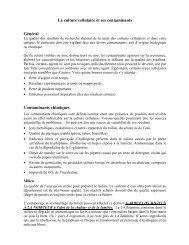
2.1 Overview<br />
1<br />
2<br />
3<br />
4<br />
1 Display<br />
– Displays relevant parameters during injection or setting<br />
of parameters.<br />
– Guides operator through functions.<br />
2 Keypad<br />
– To trigger actions.<br />
– To call up the function menu.<br />
– To switch to and from Standby mode.<br />
3 Variable regulators<br />
– To set parameters injection pressure p i , injection time t i and<br />
compensation pressure p c .<br />
– To select functions and parameters in Function mode.<br />
4 Tube connection<br />
– To connect the pressure tube to the device via the bayonet joint.<br />
6
2 Device description<br />
Standard accessories:<br />
1 Pressure tube, 2 m<br />
1 Universal capillary holder with grip head for capillary diameters<br />
of 1.0 mm and adapter for Femtotips ®<br />
1 Connecting cable (Interface Cable 5171) to the Micromanipulator 5171<br />
or InjectMan ®<br />
1 Hand control for triggering injection and the Clean function<br />
1 Femtotips ® , Femtotips ® II, Microloader and CELLocate demo pack<br />
1 Mains cable<br />
1 Operating manual<br />
Optional accessories:<br />
1 Foot control for triggering the Inject function<br />
7
2 Device description<br />
2.2 Short description<br />
Display<br />
Display of all relevant parameters and information.<br />
Function keys<br />
Clean<br />
To apply the maximum pressure for cleaning the capillary<br />
to the tube outlet.<br />
Auto / Manu<br />
To switch between manual and automatic time-controlled<br />
injection.<br />
Count<br />
To reset to zero the counter for injections which have been<br />
actuated.<br />
Inject<br />
To execute automatic or manual injection.<br />
Menu<br />
To switch the device to menu control; selected functions<br />
may be executed.<br />
Standby<br />
When the key is pressed briefly:<br />
To switch the device between operating mode and standby<br />
mode.<br />
When the key is held down:<br />
As above, but also deairs the pressure accumulator.<br />
8
2 Device description<br />
Variable regulator<br />
In the normal operating mode, the parameters for injection are set by the<br />
three variable regulators. The arrangement of the variable regulators<br />
corresponds to the arrangement of the parameters in the two bottom lines<br />
of the display:<br />
From left to right: injection pressure pi, injection time ti and compensation<br />
pressure p c .<br />
In other operating modes, the variable regulators have either the<br />
significance indicated in the display or no significance at all.<br />
Tube connection<br />
The pressure tube is connected to the device via a bayonet joint.<br />
9
2 Device description<br />
2.3 Startup<br />
3<br />
3<br />
2<br />
1<br />
Diagram of rear of device<br />
– Electrical connection is effected via the mains socket with integrated<br />
mains switch (1).<br />
– Connection to an <strong>Eppendorf</strong> manipulator designed for injection is<br />
effected via the 15-pin interface (2).<br />
– Optional switches (e.g. foot control, hand control) or a computer can<br />
be connected to the 9-pin interfaces.<br />
Switching on the device<br />
Set the mains switch on the rear of the device to "I". The unit is switched<br />
on, the display lights up, the unit runs through a warm-up routine and is<br />
then ready for operation. The injection mode is shown in the display.<br />
After being switched on, the unit runs through an initialization phase and<br />
supply pressure is built up. This takes approximately three minutes.<br />
10
2 Device description<br />
Switching off the device<br />
If it is not going to be used for an extended period, the device should<br />
be depressurized via the switch-off routine using the key. This<br />
guarantees a long service life of the device (see Section 3.1.3).<br />
The switch-off routine ensures that the system is dewatered and deaired<br />
correctly. Do not disconnect the device from the mains supply until<br />
dewatering and deairing have taken place. If only the mains switch is<br />
actuated, the existing pressure remains in the system.<br />
11
3 Mode of operation<br />
3.1 Display, variable regulators and keypad<br />
Before operating the device for the first time, users should read this<br />
section carefully. This section describes operation of the device only.<br />
Handling of the injection capillaries is described in Section 3.3.<br />
AUTO n= 0<br />
pi=<br />
150 hPa<br />
pi[hPa] ti[s] pc[hPa]<br />
150 0.2 50<br />
AUTO n= 0<br />
pi=<br />
215 PSI<br />
pi[PSI] ti[s] pc[PSI]<br />
2.15 0.2 0.72<br />
Display<br />
The display shows the following:<br />
1st line:<br />
injection mode AUTO or MANU,<br />
counter n for number of injections<br />
performed<br />
2nd line (bold):<br />
The most-recently set parameter or<br />
relevant parameter<br />
Bottom lines:<br />
Parameters which affect injection<br />
Compensation pressure p c which is<br />
applied permanently in the normal<br />
mode is displayed as an actual<br />
measured value.<br />
The arrangement of the three<br />
parameters shown, p i , t i , p c ,<br />
corresponds to the arrangement of<br />
the variable regulators.<br />
3.1.1 Setting the injection parameters<br />
The injection parameters have to be adapted to the injection capillaries<br />
used and the cell type and liquid which are to be injected.<br />
The following injection parameters can be set using the variable<br />
regulators:<br />
Injection pressure p i 0 – 6,000 hPa (0.00 – 87.0 psi)<br />
Injection time t i 0.1 – 99.9 s<br />
Compensation pressure p c 0 – 6,000 hPa (0,00 – 87.0 psi)<br />
The settings are in increments of 1 hPa/0.1 s. The display can show hPa<br />
or psi, as required. The setting and internal pressure conversion are<br />
always performed in hPa. Rounding for the display in psi can result in<br />
increments of 0.01 to 0.02 psi.<br />
The display of pressure in psi varies according to the size of the value<br />
(e.g.: 9.99 may also appear in the display as 10.0).<br />
12
3 Mode of operation<br />
Slight deviations between the nominal value (specified value) and<br />
displayed compensation pressure p c (actual value) may occur for<br />
technical reasons. The relevant value is the actual value measured.<br />
The following settings are used as a<br />
basis for initial injection experiments<br />
using Femtotip ® / Femtotip ® II:<br />
Display:<br />
AUTO n= 0<br />
pc= 50 hPa<br />
pi[hPa] ti[s] pc[hPa]<br />
150 0.5 50<br />
p i left-hand variable regulator: 150 hPa<br />
t i central variable regulator: 0.5 s<br />
p c right-hand variable regulator: 50 hPa<br />
Variable regulators:<br />
3.1.2 Variable regulators<br />
The variable regulators are set so that when they are turned slowly, the<br />
values are changed by 1 hPa / 0.1 second per notch (0.01 – 0.02 psi).<br />
If the regulators are turned faster, the values are altered in larger<br />
increments.<br />
13
3 Mode of operation<br />
3.1.3 Keypad<br />
Inject<br />
Performs automatic or manual injection.<br />
Automatic injection is controlled via the<br />
injection time t i , and the injection<br />
pressure p i is used. In the second line,<br />
injection time t i is counted down from the<br />
nominal value.<br />
AUTO - INJECT n= 0<br />
0.4 s<br />
pi[hPa] ti[s] pc[hPa]<br />
150 0.6 50<br />
<strong>Manual</strong> injection is performed for as long as the key is held down.<br />
Injection pressure pi is used. In the second line, injection time ti is counted<br />
upwards from 0.0.<br />
If the FemtoJet ® is connected to the <strong>Eppendorf</strong> Micromanipulator 5171 or<br />
Inject Man ® , the injection movement of the micromanipulator is also<br />
started via the key. Both units then combine as a system to perform<br />
semi-automatic microinjection.<br />
Alternatively, the INJECT key of the connected micromanipulator or the<br />
hand/foot control can be used.<br />
If synchronization is set to "limit" (SYNC = LIMIT) in the INJECT function<br />
of the micromanipulator, semi-automatic injection can only be triggered<br />
via the micromanipulator.<br />
Clean<br />
The maximum available pressure for<br />
cleaning is applied at the tube outlet for<br />
as long as the key is held down. Once the<br />
key is released, the pressure drops to<br />
compensation pressure p c again. The<br />
pressure curve is shown in the form of<br />
a bar.<br />
CLEAN n= 0<br />
≡≡≡≡≡≡≡≡≡≡≡≡≡≡≡_____<br />
pi[hPa] ti[s] pc[hPa]<br />
150 0.2 50<br />
14
3 Mode of operation<br />
Auto / Manu<br />
To switch between manual and<br />
automatic, time-controlled injection.<br />
In the case of manual injection, time<br />
is counted upwards from 0.0 seconds.<br />
The parameter t i is not displayed in the<br />
bottom two lines in order to emphasize<br />
that the time cannot be set via the<br />
variable regulators in this case.<br />
MANU - INJECT n= 0<br />
0.4 s<br />
pi[hPa]<br />
pc[hPa]<br />
150 50<br />
Count<br />
To reset to zero the counter for injections<br />
which have been actuated.<br />
Menu<br />
To switch the devict to menu control;<br />
selected functions may be executed.<br />
In the first line, FUNC indicates that the<br />
device is in the function menu and shows<br />
which function number is active.<br />
The second line contains the function<br />
description (e.g. "Select pressure unit").<br />
The third line requests an action (e.g.<br />
press the key to change the<br />
pressure unit). Current status: [hPa]<br />
The two bottom lines show information<br />
about which action is assigned to which<br />
variable regulator (e.g. other functions<br />
can be selected using left-hand variable<br />
regulator p i ).<br />
FUNC 1<br />
Select pressure unit<br />
INJECT = PSI<br />
Turn pi to<br />
select function<br />
[hPa]<br />
15
3 Mode of operation<br />
Standby<br />
in the case of a brief interruption<br />
When key is pressed briefly:<br />
The device switches to the Standby<br />
mode without deairing. The illumination<br />
of the display switches off. "STANDBY"<br />
appears in the display with the suffix<br />
"Supply pressure = rxyz" as a code for<br />
system pressure p s being maintained.<br />
Application:<br />
For temporary interruptions or use of<br />
as a Reset function.<br />
STANDBY<br />
Supply pressure 6789<br />
When key is pressed again:<br />
The device is reactivated and runs<br />
through a short warm-up routine.<br />
This lasts approximately one minute.<br />
Standby<br />
with deairing of pressure accumulator<br />
Hold down the key (approx. 2 seconds;<br />
the display moves to "STANDBY"):<br />
The device switches to the Standby<br />
mode. The pressure accumulator is<br />
completely deaired, the illumination of<br />
the display switches off. "STANDBY"<br />
appears in the display with the note<br />
"Supply pressure = x" (x ~ 0).<br />
A noise can be heard at this stage.<br />
Application:<br />
For correct shutdown, with deairing of the<br />
entire pressure system in the event of<br />
longer periods of non-use or standstill<br />
(weekend or storage) with subsequent<br />
switch-off using the mains switch.<br />
Press the key again:<br />
The device is reactivated and runs<br />
through the warm-up routine.<br />
This takes approximately three minutes.<br />
Hold standby<br />
to exhaust<br />
STANDBY<br />
Supply pressure 0<br />
16
3 Mode of operation<br />
Reset<br />
To reset the device to the initial mode by<br />
pressing the key briefly or via the<br />
mains switch.<br />
The pressure accumulator is not deaired.<br />
3.2 Hand control / foot control<br />
The functions of the hand/foot control<br />
correspond to the functions of the<br />
and keys on the<br />
FemtoJet ® .<br />
The centre key of the hand control has<br />
no function.<br />
The function of the foot control<br />
corresponds to the key.<br />
17
3 Mode of operation<br />
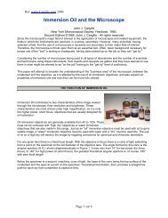
3.3 Connecting the capillary holder<br />
Universal capillary holder<br />
The universal capillary holder is used to locate the injection capillaries.<br />
Prefabricated <strong>Eppendorf</strong> Femtotips ® / Femtotips ® II (6) are screwed into<br />
the universal capillary holder using the adapter (5). To do so, the adapter<br />
for Femtotips ® (5) is first screwed into the front rotatable knurled screw<br />
(4) and then the Femtotip ® / Femtotip ® II is attached. If self-pulled<br />
capillaries are to be attached, the grip head 0 (7) needs to be screwed<br />
loosely into the front rotatable knurled screw (4). The self-pulled capillary<br />
is pushed into the front opening of the grip head through the two O-rings<br />
and fixed in position by tightening the grip head.<br />
1 2 3 4 5 6<br />
7<br />
Universal capillary holder<br />
1 Tube connection<br />
2 Rear knurled screw<br />
3 Tension piece<br />
4 Front knurled screw, rotatable<br />
5 Adapter for Femtotips ® (microcapillaries for microinjection)<br />
6 Femtotip ® / Femtotip ® II<br />
7 Grip head 0, plastic, with two O-rings and sealing washer<br />
Connecting the universal capillary holder<br />
The two-meter-long pressure tube is connected to FemtoJet ® (1) via the<br />
bayonet joint (2). The pressure tube (3) is screwed to the rear knurled<br />
screw (4) of the universal capillary holder. Femtotips ® / Femtotips ® II are<br />
fitted at the front end of the universal capillary holder (5) or independentlymanufactured<br />
capillaries are clamped with the aid of the appropriate grip<br />
head.<br />
1 2 3 4 5<br />
18
3 Mode of operation<br />
Other accessories<br />
Clamping piece<br />
for fastening the universal capillary holder.<br />
Not required for TransferMan ® NK or for <strong>Eppendorf</strong><br />
micromanipulators, which have an adjustable<br />
cannula holder.<br />
The universal capillary holder is mounted to the<br />
micromanipulator by placing the clamping piece into<br />
the tool holder of the <strong>Eppendorf</strong> Micromanipulator<br />
and then tightening it with the fastening screw.<br />
The universal capillary holder is positioned with<br />
the correct length into the tool holder and then fixed<br />
into position. The position of the capillary can be<br />
changed by loosening the fastening screw.<br />
Grip head 0,<br />
incl. 2 sets of O-rings and sealing washer.<br />
Using grip head 0 supplied, capillaries with an outer<br />
diameter of 1.0 mm to 1.1 mm can be used. In the<br />
case of outer diameters which differ from these<br />
measurements, the relevant grip heads can be<br />
ordered as non-standard accessories for the<br />
universal capillary holder (see Section 7, Ordering<br />
information). The transparent grip head allows the<br />
user to visually monitor the position of the capillary.<br />
19
3 Mode of operation<br />
3.4 Information on working practices<br />
The following pressures can be used:<br />
Name Pressure range Comments<br />
Compensation<br />
pressure p c<br />
0 – 6,000 hPa<br />
0.00 – 87.0 psi<br />
Injection pressure p i<br />
0 – 6,000 hPa<br />
0.00 – 87.0 psi<br />
Clean pressure<br />
maximum<br />
up to 7,000 hPa<br />
maximum up to 102 psi<br />
Constant working<br />
pressure p w<br />
0 – 6,000 hPa<br />
0.00 – 87.0 psi<br />
Select Function 4 via<br />
the key.<br />
System pressure p s<br />
[supply pressure]<br />
maximum<br />
up to 7,000 hPa<br />
maximum up to 102 psi<br />
This is used directly<br />
for .<br />
In certain phases of<br />
initialization, the<br />
system pressure may<br />
temporarily increase<br />
to a maximum of<br />
8,000 hPa (117 psi).<br />
20
3 Mode of operation<br />
3.4.1 Compensation pressure p c<br />
The compensation pressure p c ensures that no medium flows into the<br />
capillary. Capillary forces would make liquid flow out of the cell culture<br />
dish into the injection capillary and thus dilute the injection material. To<br />
prevent this, a permanent compensation pressure p c is set. This should<br />
be selected so that there is a permanent slight flow-out of liquid from the<br />
injection capillary. The individual pressure level can be determined in a<br />
preliminary test. For example, a fluorescent dye can be added to the<br />
capillary to enable outflow to be monitored directly. The pressure required<br />
is heavily dependent on the surface tension and viscosity of the injection<br />
material. Experience has shown that compensation pressures of between<br />
30 hPa and 300 hPa (0.44 – 4.4 psi) are appropriate values for ready-touse<br />
<strong>Eppendorf</strong> Femtotips ® injection capillaries.<br />
Capillary suction<br />
Compensation pressure p c<br />
Hydrostatic pressure P hyd<br />
Pressure in the capillaries<br />
3.4.2 Injection pressure p i<br />
Injection pressure p i is applied during the injection process. This pressure<br />
is generally higher than the compensation pressure. In many cases, a<br />
pressure between 50 hPa and 500 hPa (0.73 – 7.2 psi) is appropriate for<br />
Femtotips ® . The volume injected is dependent on the injection pressure<br />
and the injection time. The injection pressure must be greater than<br />
the internal pressure of the cell into which injection should take place.<br />
However, if the cell or the cell nucleus swell up during injection, the<br />
injection pressure is too high.<br />
If the compressor starts up occasionally during experiments, this does not<br />
impair the function of the FemtoJet ® . Pressure is always available up to<br />
the maximum value of 6,000 hPa (approx. 87.0 psi), even when the<br />
compressor is topping up the supply pressure.<br />
21
3 Mode of operation<br />
3.4.3 Injection time t i<br />
Injection time t i gives the period for which injection pressure p i is<br />
maintained. t i is usually selected from a range between approx. 0.3 s and<br />
1.5 s. The relevant factor for the injected volume is the product of the<br />
injection pressure and the injection time.<br />
Depending on the setting on the <strong>Eppendorf</strong> Micromanipulator which is<br />
connected, the injection time t i is measured from the point at which the<br />
key is pressed. The injection pressure is built up immediately, so it<br />
is already present during the injection movement and during penetration<br />
of the cell. Once the end of injection time has been reached, the device<br />
switches to compensation pressure p c . At the same time, the micromanipulator<br />
is moved back into the working level. When "Injection at Z limit" is<br />
set, measurement of the injection time t i does not begin until the Z limit<br />
has been reached. Once t i has elapsed, the FemtoJet ® switches back to<br />
p c and the micromanipulator moves back into its starting position in the<br />
working level.<br />
3.4.4 Clean function<br />
The Clean function is used to flush out blocked capillaries. The maximum<br />
available pressure is applied to the outlet with the key. It is applied<br />
for as long as the key is pressed. The maximum pressure of the<br />
FemtoJet ® is in the range of 7,000 hPa (102 psi). The value cannot be<br />
changed.<br />
The pressure curve up to maximum pressure appears in the display in the<br />
form of a bar chart. By pressing the key briefly, a lower pressure<br />
can also be obtained.<br />
22
3 Mode of operation<br />
3.4.5 <strong>Manual</strong> or automatic injection<br />
In the Manu operating mode, injection is performed for as long as the<br />
key or hand / foot control is held down. The duration (t i ) of<br />
injection is measured and shown in the display. In the case of<br />
combination with an <strong>Eppendorf</strong> Micromanipulator, the injection movement<br />
is triggered.<br />
In the Auto operating mode, the built-in timer facilitates a reproducible<br />
injection time. The injection runs automatically for the duration of set time<br />
t i . It is triggered by the key or the hand / foot control being pressed<br />
briefly. During injection, the Inject key is inactive, i.e. pressing it again has<br />
no effect. In combination with an <strong>Eppendorf</strong> Micromanipulator 5171 /<br />
InjectMan ® , the automatic injection procedure can also be triggered from<br />
the operating panel of the micromanipulator.<br />
3.4.6 Constant pressure/constant working pressure<br />
Using the Constant Pressure function, it is possible to select a higher<br />
pressure permanently if required. This function is helpful when special<br />
injection techniques require either a high pressure up to a maximum of<br />
6,000 hPa (87 psi) or a permanent flow of injection solution<br />
(see Section 3.7.5). Control accuracy drops in the pressure range from<br />
2,000 – 6,000 hPa (29 – 87 psi).<br />
3.4.7 General note<br />
FemtoJet ® is fitted with an integrated compressor. For this reason, the<br />
compressor may start up or excess pressure may be let off briefly before,<br />
during and after injections or during periods when the FemtoJet ® is not<br />
being used. This is not a malfunction of the device and does not impair<br />
injection.<br />
In the case of injections under high pressure at very short intervals<br />
or in the case of the Clean function being carried out several times<br />
in succession, the pressure in the system accumulator may drop<br />
significantly. This is indicated by a warning or an error message. In this<br />
case, wait a short time until the supply pressure has stabilized again.<br />
It is then possible to continue working immediately.<br />
23
3 Mode of operation<br />
3.5 The first injection<br />
The following are available:<br />
● Adherent cells in a Petri dish (possibly on CELLocates to observe<br />
specific cells after injection),<br />
● Injection liquid (purified, e.g. by centrifugation),<br />
● Femtotips ® / Femtotips ® II; other capillaries as an alternative<br />
● Microloader,<br />
● 0.5 – 10 µl pipette to take the Microloader,<br />
●<br />
A universal capillary holder on the micromanipulator which has been<br />
preadjusted with a Femtotip ® .<br />
Filling the Femtotips ® with the Microloader:<br />
– Select function 0 "Capillary exchange" by pressing . Connect<br />
the pressure tube.<br />
– Aspirate approximately 0.5 – 5.0 µl of centrifuged injection fluid with<br />
the Microloader without touching the base of the vessel. Using the<br />
Microloader, fill the Femtotip ® through the rear opening, inserting the<br />
tip approximately up to the centre of the Femtotips ® and releasing the<br />
fluid there.<br />
– Hold the Femtotip ® vertically, loosen the cap by turning it and allow it<br />
to drop vertically.<br />
– Screw the Femtotip ® into the capillary holder.<br />
– Complete Function 0 by pressing . Compensation pressure is<br />
applied.<br />
– Move the capillary into the cell medium (Petri dish) with the micromanipulator.<br />
– Focus the cells with the microscope, position the capillary slightly<br />
above the cells but do not allow it to come into contact with the base<br />
of the Petri dish. Focus the capillary.<br />
– Using the key, check that the capillary is not blocked. Either<br />
the fluid can be seen flowing out or it is rendered visible by the<br />
fluorescent substance it entrains. As a rule, any air bubbles present<br />
are blown out.<br />
– Perform a sample injection using the preset parameters<br />
(e.g. p i ~ 150 hPa, t i ~ 0.5 s, p c ~ 50 hPa, corresponding to<br />
p i ~ 2.18 psi, t i ~ 0.5 s, p c ~ 0.73 psi). Injection can be monitored<br />
visually when the cell size changes by approx. 5 % to 10 % or via<br />
fluorescence. If required, adapt parameters p i and/or t i .<br />
24
3 Mode of operation<br />
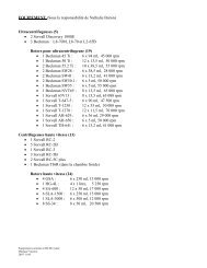
3.6 Connecting an <strong>Eppendorf</strong> Micromanipulator<br />
Connection to an <strong>Eppendorf</strong> Micromanipulator designed for automated<br />
injection is effected with the 15-pin interface.<br />
1<br />
3 4 5<br />
8<br />
2<br />
7<br />
6<br />
FemtoJet ® (rear) with all connection options<br />
1 Foot control (optional) with Inject function<br />
2 Hand control with Inject and Clean functions<br />
3 FemtoJet ®<br />
4 Micromanipulator 5171 or InjectMan ®<br />
5 Connection socket of micromanipulator for<br />
Transmission cable 5246 ("Y cable")<br />
6 Transmission cable 5246<br />
(accessory for Micromanipulator 5171 and InjectMan ® )<br />
7 Interface cable 5171<br />
(Connection from FemtoJet ® to Transmission cable 5246 "Y cable")<br />
8 Interface of FemtoJet ® to micromanipulator<br />
25
3 Mode of operation<br />
3.7 Functions<br />
The Function menu is called up using the key. One of seven<br />
functions is selected using left-hand variable regulator p i . The relevant<br />
functionality is assigned to the variable regulators in the bottom line of the<br />
display.<br />
Exit the Function menu by pressing the key again.<br />
In cases of error, pressure control is switched off from within the Function<br />
menu. Then exit the Menu using the key.<br />
Function 6, self-test, is described in Section 5, "Troubleshooting".<br />
3.7.1 Changing the capillaries<br />
FUNC 0<br />
Change capillary<br />
Capillary may be<br />
changed now<br />
Turn pi to<br />
select function<br />
FUNC 0<br />
When this function is called up, the<br />
pressure tube is deaired and any<br />
pressure present in the system is let out.<br />
Once the capillary has been changed,<br />
exit the function using the key or<br />
variable regulator p i ; pressure control will<br />
restart.<br />
3.7.2 Setting the pressure unit<br />
FUNC 1<br />
Push Inject to select<br />
Pressure Unit hPa PSI<br />
Turn pi to<br />
select function<br />
FUNC 1<br />
The other pressure unit is selected using<br />
the key and all pressure values<br />
are converted. The pressure unit<br />
currently selected (in this case: hPa)<br />
is underlined.<br />
26
3 Mode of operation<br />
3.7.3 Switching on/off the loudspeaker<br />
FUNC 2<br />
Push Inject to select<br />
Beeper<br />
ON OFF<br />
Turn pi to<br />
select function<br />
FUNC 2<br />
Use the key to switch the<br />
loudspeaker on or off. The currently<br />
selected setting (in this case: ON) is<br />
underlined. Acoustic error messages are<br />
not emitted if the setting<br />
is OFF.<br />
3.7.4 Switching on/off the background illumination of the display<br />
FUNC 3<br />
Push Inject to select<br />
Illumination ON OFF<br />
Turn pi to<br />
select function<br />
FUNC 3<br />
Use the key to switch the<br />
illumination on or off. The currently<br />
selected setting (in this case: ON) is<br />
underlined.<br />
In the normal operating mode,<br />
illumination switches off after three<br />
minutes if no operating control has been<br />
actuated. When an operating control is<br />
actuated, the illumination lights up again.<br />
3.7.5 Constant pressure<br />
FUNC 4<br />
Continuous flow<br />
INJECT = start<br />
Turn pi to<br />
select function<br />
FUNC 4<br />
Continuous flow<br />
pw= 50 hPa<br />
Turn pi to<br />
pw[hPa]<br />
select function 50<br />
FUNC 4<br />
This function can be used to apply a<br />
constant working pressure pw in the<br />
range from approx. 0 to 6,000 hPa<br />
(87.0 psi) at the pressure outlet. The<br />
pressure unit psi can also be used.<br />
The working pressure p w is set with<br />
the right-hand variable regulator (p c ),<br />
the specified value is shown in large<br />
characters. The actual value is shown<br />
in the bottom right of the display.<br />
The Clean function can be activated. The<br />
pressure of the Clean function is shown<br />
in the bottom right of the display in the<br />
form of p w .<br />
27
3 Mode of operation<br />
3.7.6 Dewatering the pressure accumulator<br />
FUNC 5<br />
Drain pressure supply<br />
INJECT = start<br />
Turn pi to<br />
select function<br />
FUNC 5<br />
– Briefly opens the dewatering valve<br />
of the pressure accumulator; any<br />
condensed humidity present is blown<br />
away.<br />
– When this function is performed, the<br />
noise of air being blown away can be<br />
heard.<br />
This function is automatically performed<br />
every time the unit is switched on. It can<br />
be performed manually as described if<br />
condensation is suspected to be present.<br />
28
4 Care and maintenance<br />
4.1 Cleaning<br />
Before cleaning the FemtoJet ® , disconnect the plug.<br />
Ensure that no fluids enter into the inside of the injector in order to avoid<br />
short-circuits in the electrical installation as well as corrosion.<br />
Wipe painted parts and aluminum surfaces using a cloth and mild<br />
detergent and then with a dry cloth.<br />
Warning: Do not use any corrosive, solvent or abrasive detergents<br />
or polishes.<br />
4.2 Disinfection<br />
Clean the FemtoJet ® before disinfecting.<br />
Wipe every part of the FemtoJet ® , including accessories and connector<br />
cables, with disinfectant.<br />
Spray disinfection is not advisable, as disinfectants can enter into the<br />
microinjector.<br />
The disinfection method used must comply with current disinfection<br />
regulations and guidelines.<br />
4.3 Maintenance<br />
Regular maintenance is not required.<br />
The dealer is responsible for warranty and service.<br />
29
5 Troubleshooting<br />
5.1 Potential errors<br />
– Pressure loss due to capillary not fitted with capillary holder<br />
connected.<br />
Solution: Connect the capillary or select Function 0, Change capillary,<br />
via the key and variable regulator p i .<br />
– Capillary is blocked.<br />
Solution: Press the key for long enough.<br />
Change capillary.<br />
Purify injection fluid (e.g. by means of centrifugation).<br />
– Compressor runs for a long time.<br />
Solution: Take a short break.<br />
Do not use the key too often within a short period.<br />
If possible, set a lower compensation pressure p c.<br />
Perform self-test (Section 5.1.1).<br />
– Valve rattles<br />
Solution: Connect tube to filled capillary. Pressure control is designed<br />
for the tube connected.<br />
– No communication with the micromanipulator.<br />
Solution: Check cables and connections.<br />
5.1.1 Self-test<br />
FUNC 6<br />
Self-Test<br />
INJECT = Complete<br />
CLEAN = Leak only<br />
Connect closed tube !<br />
Turn pi to<br />
select function<br />
FUNC 6<br />
The FemtoJet ® is checked for leaks in<br />
the self-test.<br />
This self-test can also be used if a leak is<br />
suspected.<br />
The test runs automatically.<br />
The pressure tube must be connected to<br />
a closed capillary (e.g. melted closed or<br />
filled) for the pressure control to work<br />
properly.<br />
30
5 Troubleshooting<br />
FUNC 6<br />
Self-Test<br />
Compressor _____ s<br />
Ps leak _____ _____ hPa<br />
Pw leak _____ _____ hPa<br />
Injection _____ _____ hPa<br />
ps=7000 pw= 10 hPa<br />
key: Complete self-test<br />
– Checks compressor run time up to<br />
the point when a specific pressure<br />
is reached and thus for leaks in the<br />
area of the compressor.<br />
– In the case of two different<br />
pressures, checks for leaks in the<br />
pressure accumulator (p s ) and for<br />
the internal tightness of the valves.<br />
– Checks for leaks in the area of<br />
working pressure (p w ) in the case<br />
of two different pressures.<br />
– Checks behavior during injection<br />
at different pressures (short<br />
continuous test).<br />
If certain values are outside the specified<br />
range, an error message is emitted. If this<br />
recurs, inform Service.<br />
FUNC 6<br />
Self-Test<br />
Ps leak _____ _____ hPa<br />
Pw leak _____ _____ hPa<br />
ps=7000 pw= 10 hPa<br />
key: Self-test to search for leaks<br />
– Checks for leaks in the pressure<br />
accumulator (p s ) in the case of two<br />
different pressures, as well as for<br />
inner tightness of the valves.<br />
– Checks for leaks in the area of working<br />
pressure (p w ) in the case of two<br />
different pressures.<br />
If certain values are outside the specified<br />
range, an error message is emitted. If this<br />
recurs, inform Service.<br />
31
5 Troubleshooting<br />
5.2 Warnings<br />
As a rule, warnings are emitted if certain operating conditions are not (yet)<br />
reached or if an action is not possible.<br />
Acknowledge the warning with the key and the unit will return to<br />
normal status.<br />
WARNING 001<br />
Please wait for<br />
supply pressure<br />
INJECT = Continue<br />
Warning 1<br />
Supply pressure has not yet been<br />
reached.<br />
The minimum supply pressure required<br />
for an injection or the Clean function was<br />
not present when the function was<br />
triggered.<br />
Possible cause:<br />
Multiple triggering of Clean or very rapid<br />
injection at a high injection pressure.<br />
Solution:<br />
Wait until the supply pressure has built up<br />
and trigger again.<br />
WARNING 002<br />
Check capillary<br />
e.g. broken/missing <br />
INJECT = Continue<br />
Warning 2<br />
Compensation pressure cannot be<br />
maintained.<br />
Possible cause:<br />
Capillary or capillary holder not attached<br />
or only connected loosely.<br />
Solution:<br />
Check all connections and tighten.<br />
Activate Function 0 to change the<br />
capillary and when the capillary holder is<br />
open.<br />
32
5 Troubleshooting<br />
WARNING 003<br />
Switch on manipulator<br />
or disconnect cable<br />
INJECT = Continue<br />
Warning 3<br />
Micromanipulator does not react<br />
A micromanipulator is connected but<br />
does not react to a start pulse from the<br />
FemtoJet ® .<br />
Possible cause:<br />
Micromanipulator is switched off.<br />
INJECT function on manipulator is not<br />
released.<br />
No limit is set on the micromanipulator.<br />
In the INJECT function on the micromanipulator,<br />
synchronization is set to<br />
limit (SYNC = LIMIT).<br />
Solution:<br />
Switch on the micromanipulator and<br />
make it operational.<br />
Disconnect the cable to micromanipulator.<br />
With SYNC = LIMIT, trigger semi-automatic<br />
injection via the micromanipulator<br />
only.<br />
5.3 Error messages<br />
Error messages are emitted if certain operating conditions are not<br />
reached or the device records a deviation from specified conditions.<br />
Acknowledge the error message with the key and the unit will<br />
return to normal status. The measures described under “Solution” should<br />
be carried out. If the error message recurs after acknowledgement with<br />
the key, inform Service.<br />
33
5 Troubleshooting<br />
ERROR 010<br />
Supply pressure<br />
cannot be reached<br />
INJECT = Continue<br />
ERROR 011<br />
Supply pressure is<br />
too high<br />
INJECT = Continue<br />
ERROR 012<br />
Supply pressure is<br />
does not fall<br />
INJECT = Continue<br />
Error 10<br />
Supply pressure cannot be reached<br />
The compressor runs without the<br />
maximum supply pressure being<br />
reached.<br />
Possible cause:<br />
High compensation pressure when the<br />
capillary holder is not attached or is<br />
poorly attached.<br />
Technical cause:<br />
Compressor does not start up. Leak in<br />
compressor or pressure accumulator.<br />
Solution:<br />
Check the capillary holder and tube for<br />
leaks or tighten up the tube connections.<br />
Service.<br />
Error 11<br />
Supply pressure is too high<br />
Supply pressure has exceeded the<br />
maximum permissible supply pressure.<br />
Possible cause:<br />
supply pressure is not relieved by the<br />
relevant standby function.<br />
Technical defect.<br />
Solution:<br />
Switch off using the key (hold<br />
down for approximately two seconds).<br />
Service.<br />
Error 12<br />
Supply pressure does not drop far<br />
enough<br />
Possible cause: Technical defect<br />
Solution: Service<br />
34
5 Troubleshooting<br />
ERROR 013<br />
Supply pressure is<br />
does not raise<br />
INJECT = Continue<br />
ERROR 014<br />
Supply pressure<br />
leak is too high<br />
INJECT = Continue<br />
ERROR 015<br />
Supply pressure<br />
leak is too high<br />
INJECT = Continue<br />
ERROR 016<br />
Valve 1 pressure<br />
leak is too high<br />
INJECT = Continue<br />
ERROR 020<br />
Working pressure<br />
cannot be reached<br />
INJECT = Continue<br />
Error 13<br />
Supply pressure does not rise<br />
Possible cause: Technical defect<br />
Solution: Service<br />
Error 14<br />
Massive leak in pressure accumulator<br />
Possible cause: Technical defect<br />
Solution: Service<br />
Error 15<br />
Leak in pressure accumulator<br />
Possible cause: Technical defect<br />
Solution: Service<br />
Error 16<br />
Leak through Valve V1 is too large<br />
Possible cause: Technical defect<br />
Solution: Service<br />
Error 20<br />
Working pressure has not been reached<br />
Compressor runs without supply<br />
pressure being reached within a specific<br />
time.<br />
Possible cause:<br />
Capillary holder not attached or poorly<br />
attached. (Broken) capillary with large<br />
opening.<br />
Technical defect.<br />
Solution:<br />
Check the capillary. Check the capillary<br />
holder and tube for leaks or tighten up the<br />
tube connections.<br />
Service.<br />
35
5 Troubleshooting<br />
ERROR 021<br />
Inject pressure<br />
cannot be reached<br />
INJECT = Continue<br />
ERROR 022<br />
Compensation pressure<br />
cannot be reached<br />
INJECT = Continue<br />
ERROR 023<br />
Inject n pressure<br />
overflow too large<br />
INJECT = Continue<br />
ERROR 024<br />
Working pressure<br />
does not rise<br />
INJECT = Continue<br />
Error 21<br />
Injection pressure has not been reached<br />
Possible cause:<br />
Capillary holder not attached or poorly<br />
attached. (Broken) capillary with large<br />
opening.<br />
Technical defect.<br />
Solution:<br />
Check capillary. Check capillary holder<br />
and tube for leaks or tighten up tube<br />
connections.<br />
Service.<br />
Error 22<br />
Compensation pressure has not been<br />
reached<br />
Possible cause:<br />
Capillary holder not attached or poorly<br />
attached. (Broken) capillary with large<br />
opening.<br />
Technical defect.<br />
Solution:<br />
Check capillary. Check capillary holder<br />
and tube for leaks or tighten up tube<br />
connections.<br />
Service.<br />
Error 23<br />
Increase in working pressure is smaller<br />
than required<br />
Possible cause: Technical defect<br />
Solution: Service<br />
Error 24<br />
No increase in working pressure<br />
Possible cause: Technical defect<br />
Solution: Service<br />
36
5 Troubleshooting<br />
ERROR 025<br />
Working pressure<br />
does not fall<br />
INJECT = Continue<br />
ERROR 026<br />
Working pressure<br />
leak is too high<br />
INJECT = Continue<br />
ERROR 027<br />
Working pressure<br />
leak is too high<br />
INJECT = Continue<br />
Error 25<br />
No drop in working pressure<br />
Possible cause: Technical defect<br />
Solution: Service<br />
Error 26<br />
Working pressure leak rate is too high<br />
Possible cause:<br />
Capillary holder not attached or poorly<br />
attached. (Broken) capillary with large<br />
opening.<br />
Technical defect.<br />
Solution:<br />
Check capillary. Check capillary holder<br />
and tube for leaks or tighten up tube<br />
connections.<br />
Service.<br />
Error 27<br />
Working pressure leak rate is too high<br />
Possible cause:<br />
Capillary holder not attached or poorly<br />
attached. (Broken) capillary with large<br />
opening.<br />
Technical defect.<br />
Solution:<br />
Check capillary. Check capillary holder<br />
and tube for leaks or tighten up tube<br />
connections.<br />
Service.<br />
37
5 Troubleshooting<br />
ERROR 028<br />
Working pressure<br />
leak is too high<br />
INJECT = Continue<br />
ERROR 030<br />
Sensoroffset supply<br />
is too low<br />
INJECT = Continue<br />
ERROR 031<br />
Sensoroffset supply<br />
is too high<br />
INJECT = Continue<br />
ERROR 032<br />
Sensoroffset work<br />
is too low<br />
INJECT = Continue<br />
ERROR 033<br />
Sensoroffset work<br />
is too high<br />
INJECT = Continue<br />
ERROR 034<br />
Valve 1 offset<br />
is too low<br />
INJECT = Continue<br />
Error 28<br />
Working pressure leak rate is too high<br />
Possible cause:<br />
Capillary holder not attached or poorly<br />
attached. (Broken) capillary with large<br />
opening.<br />
Technical defect.<br />
Solution:<br />
Check capillary. Check capillary holder<br />
and tube for leaks or tighten up tube<br />
connections.<br />
Service.<br />
Error 30<br />
Sensor offset supply pressure is too low<br />
Possible cause: Technical defect<br />
Solution: Service<br />
Error 31<br />
Sensor offset supply pressure is too high<br />
Possible cause: Technical defect<br />
Solution: Service<br />
Error 32<br />
Sensor offset working pressure is too low<br />
Possible cause: Technical defect<br />
Solution: Service<br />
Error 33<br />
Sensor offset working pressure is too<br />
high<br />
Possible cause: Technical defect<br />
Solution: Service<br />
Error 34<br />
Valve 1 offset is too low<br />
Possible cause: Technical defect<br />
Solution: Service<br />
38
5 Troubleshooting<br />
ERROR 035<br />
Valve 1 offset<br />
is too high<br />
INJECT = Continue<br />
ERROR 036<br />
Valve 2 offset<br />
is too low<br />
INJECT = Continue<br />
ERROR 037<br />
Valve 2 offset<br />
is too high<br />
INJECT = Continue<br />
ERROR 040<br />
Self-Calibration<br />
is missing<br />
INJECT = Continue<br />
ERROR 041<br />
Fullscale Calibration<br />
is missing<br />
INJECT = Continue<br />
Error 35<br />
Valve 1 offset is too high<br />
Possible cause: Technical defect<br />
Solution: Service<br />
Error 36<br />
Valve 2 offset is too low<br />
Possible cause: Technical defect<br />
Solution: Service<br />
Error 37<br />
Valve 2 offset is too high<br />
Possible cause: Technical defect<br />
Solution: Service<br />
Error 40<br />
Self-calibration is missing<br />
Possible cause: Technical defect<br />
Solution: Service<br />
Error 41<br />
Full-scale calibration is missing<br />
Possible cause: Technical defect<br />
Solution: Service<br />
39
6 Technical data<br />
Voltage/Frequency: 100 V – 240 V ± 10 %, 50 – 60 Hz<br />
Set voltage:<br />
adapts automatically<br />
Fuse for 100 – 240 V: T1.0 A, 250 V (2 pcs.)<br />
Power consumption: 50 W<br />
Max. current consumption: < 0.5 A<br />
Protection class:<br />
I<br />
Overvoltage category: II (IEC 61010-1)<br />
Pollution degree: 2 (IEC 664)<br />
Ambient temperature: 15 °C – 35 °C<br />
Ambient relative humidity: max. 70 %<br />
Weight:<br />
6.2 kg<br />
Dimensions: Width: 220 mm<br />
Depth: 170 mm<br />
Height: 280 mm<br />
Injection time t i :<br />
0.0 – 99.9 s<br />
in 0.1 s increments<br />
Injection pressure p i : 0 – 6,000 hPa (87 psi),<br />
in 1 hPa (0.01–0.02 psi) increments<br />
Regulating accuracy: 1 % of value set in each case,<br />
at least ± 1 hPa<br />
Compensation pressure p c : 0 – 6,000 hPa (87 psi),<br />
in 1 hPa (0.01–0.02 psi) increments<br />
Regulating accuracy: 1 % of value set in each case,<br />
at least ± 1 hPa<br />
Clean rinsing pressure: max. approx. 7,000 hPa (102 psi)<br />
RS 232 computer Baud rate: 9,600<br />
interface: Start bit: 1<br />
Data bits: 8<br />
Parity: non<br />
Stop bit: 1<br />
The device is approved with the<br />
sign.<br />
Technical specifications subject to change!<br />
40
7 Ordering information<br />
Order no.<br />
5247 000.013 FemtoJet ®<br />
100 V – 240 V ± 10 %, 50 – 60 Hz<br />
Fully programmable microinjector with integrated<br />
pressure supply. For injection of smallest amounts<br />
of liquid into living cells.<br />
Delivery package:<br />
1 FemtoJet ®<br />
1 Power cable<br />
1 Interface cable 5171<br />
1 Universal capillary holder<br />
1 Pressure tube, 2 m<br />
5247 617.002 1 Hand control for remote control<br />
10 Femtotips ® / Femtotips ® II (injection capillaries)<br />
10 Microloader<br />
20 CELLocates<br />
1 Operating <strong>Manual</strong><br />
Accessories (not standard)<br />
5247 623.002 Foot control FemtoJet ®<br />
5325 620.007 Interface cable PC<br />
for control and for program updates<br />
5247 622.006 Interface cable 5171<br />
for connection to the micromanipulator<br />
5242 952.008 20 Femtotips ®<br />
5242 957.000 20 Femtotips ® II<br />
5242 956.003 200 Microloader<br />
5246 164.004 1 Pressure tube, 2 m, for universal capillary holder<br />
5176 190.002 Universal capillary holder<br />
(incl. grip head 0, adapter for Femtotips ® ,<br />
clamping piece and spare O-rings)<br />
4910 000.018 <strong>Eppendorf</strong> Reference ® pipette, variable, 0.5 to 10 µl<br />
3110 000.021 <strong>Eppendorf</strong> Research ® pipette, variable, 0.5 to 10 µl<br />
5176 210.003 Grip head 0 for universal capillary holder;<br />
for microcapillaries with an outer diameter<br />
of 1.0 to 1.1 mm<br />
5176 212.006 Grip head 1 for universal capillary holder;<br />
for microcapillaries with an outer diameter<br />
of 1.2 to 1.3 mm<br />
5176 214.009 Grip head 2 for universal capillary holder;<br />
for microcapillaries with an outer diameter<br />
of 1.4 to 1.5 mm<br />
41
7 Ordering information<br />
5176 207.002 Grip head 3 for universal capillary holder<br />
for microcapillaries with an outer diameter<br />
of 0.7 to 0.8 mm<br />
5176 196.000 O-ring set<br />
for grip heads 0 to 3 with extraction tool<br />
5176 195.004 Service kit<br />
for grip head and capillary holder,<br />
consisting of O-ring set, adapter for Femtotip ®<br />
and clamping piece<br />
CELLocate<br />
Glass coverslips with integrated microgrid<br />
for relocating cells in light and electron microscopy,<br />
individually sealed, with log pad<br />
5245 952.009 Grid size 175 µm, sterile, set of 80<br />
5245 962.004 Grid size 55 µm, sterile, set of 80<br />
Micromanipulation<br />
5171 000.019 Micromanipulator 5171<br />
Programmable micromanipulator with<br />
coordinate storage for automatic microinjection,<br />
microdissection and electrophysiology<br />
(in combination with FemtoJet ® ),<br />
complete with power unit, module unit<br />
and control board<br />
5179 000.018 InjectMan ®<br />
Micromanipulator for automatic injection<br />
in adherent cells in combination with FemtoJet ® ,<br />
complete with power unit, module unit<br />
and control board<br />
5178 000.014 TransferMan ® NK<br />
Proportional micromanipulator for<br />
microinjection in suspension cells<br />
5177 000.010 TransferMan ®<br />
Dynamic micromanipulator for<br />
microinjection in suspension cells<br />
5246 621.006 Transmission cable 5246<br />
"Y cable" for connection with the<br />
interface cable 5171<br />
5211 058.007 Foot control for microinjection,<br />
connectable to transmission cable 5246 "Y cable"<br />
42
8 Index<br />
A<br />
Adapter for Femtotips ® 18<br />
Application 3, 4<br />
C<br />
Capillary change 26<br />
Clean 8<br />
pressure 20<br />
function 22<br />
Cleaning 29<br />
Commands 45<br />
Compressor 21, 23<br />
Compensation pressure pc 5, 20, 21<br />
Connection<br />
capillary holder 18<br />
micromanipulator 25<br />
universal capillary holder 18<br />
Constant<br />
pressure 23, 27<br />
working pressure 23<br />
working pressure p w 20<br />
D<br />
Disinfection 29<br />
Display 6, 8, 12<br />
in hPa 12<br />
in psi 12<br />
switch on/off 27<br />
E<br />
Error<br />
messages 33<br />
potential 30<br />
F<br />
Foot control 7, 17<br />
Functions 26<br />
keys 8<br />
menu 15<br />
G<br />
Grip head 18, 19<br />
H<br />
Hand control 17<br />
I<br />
Information on working practices 20<br />
Injection<br />
automatic 14, 23<br />
first 24<br />
manual 14, 23<br />
movement 14, 23<br />
parameters 12<br />
pressure pi 5, 14, 20, 21<br />
time t i 5, 14, 22<br />
trial 24<br />
Interface 10, 25<br />
description 45<br />
K<br />
Key<br />
Auto/Manu 8, 14<br />
Clean 8, 14, 22<br />
Count 8, 15<br />
Inject 5, 8, 14, 32<br />
Menu 8, 26<br />
Standby 8, 16<br />
Keypad 6, 14<br />
L<br />
Loudspeaker, switch on/off<br />
M<br />
Mains switch 10<br />
Menu 15<br />
Mode of operation 12<br />
O<br />
Operation 12<br />
via computer 43, 45<br />
Ordering information 41<br />
Overview 6<br />
43
8 Index<br />
P<br />
Pressure<br />
– dewatering<br />
pressure accumulator 28<br />
– set pressure unit 26<br />
tube 9, 18<br />
Q<br />
Query 45<br />
R<br />
Reset 9, 17<br />
function 16<br />
S<br />
Safety precautions 3, 4<br />
Self-test 30<br />
complete 31<br />
to find leaks 31<br />
Servicing 29<br />
Short description 8<br />
Startup 10<br />
Standby without deairing 16<br />
Switch<br />
on 10<br />
off 11<br />
System pressure ps 20<br />
T<br />
Technical data 40<br />
Tension piece 19<br />
Troubleshooting 30<br />
Tube connection 6, 9<br />
U<br />
Unit<br />
description 5<br />
rear of 10<br />
Universal capillary holder 18<br />
V<br />
Variable regulator 5, 6, 9, 13, 26<br />
W<br />
Warnings 32<br />
44
Appendix A<br />
Operation via a computer<br />
Certain commands and queries (Section 6.2) can be transmitted to the<br />
unit using the optional cable/PC interface.<br />
A.1 Description of interface<br />
A computer can be connected to the remote control of the FemtoJet ® via<br />
one of the two RS 232 interfaces. Parameters can be entered or read out<br />
via the computer.<br />
The computer is connected by the special cable/PC interface cable.<br />
The computer to be connected must comply with EN 60950/UL 1950<br />
standards.<br />
The serial interface of the computer should be set to the following transmission<br />
parameters:<br />
Baud rate: 9,600<br />
Start bit: 1<br />
Dat bits: 8<br />
Parity: non<br />
Stop bit: 1<br />
Only ASCII symbols (incl. CR/LF) which can be represented are<br />
transmitted.Therefore a terminal program, for example, is suitable for<br />
remote control.<br />
A.2 Commands and queries<br />
The commands to be sent are defined with the following structure:<br />
Commands to enter parameters:<br />
"Cxxx=ssssssssss"<br />
Commands to execute and to read out parameters:<br />
"Cxxx"<br />
C: Command<br />
xxx: Code for the executing command<br />
=: Separation for the following input parameters<br />
ssssssssss: Input parameters<br />
In response to any command, the device provides a symbol string of a<br />
similar structure:<br />
"Axxx" for answers without output parameter<br />
"Axxx=rrrrrrrrrr" for responses with output parameter<br />
A: Answer<br />
45
Appendix A<br />
If the command is faulty, an error message is returned instead of the<br />
answer:<br />
"ERR=eee"<br />
ERR: Error<br />
=: Separation<br />
eee: Error number<br />
Lower and upper case letters can be used.<br />
Command to enter<br />
parameters<br />
[C]<br />
Code Input Meaning of<br />
parameter input parameters<br />
[xxx] [ssssssssss]<br />
Short acoustic signal 003 1 – 254 Number of signals<br />
Long acoustic signal 004 1 – 254 Number of signals<br />
Automatic injection<br />
(inject at t i )<br />
Set injection counter n<br />
to 0<br />
010 0; 1 – 999 Injection time<br />
in 1/10 seconds<br />
0: injection time set on<br />
the FemtoJet ®<br />
012 – – – No parameter input<br />
Perform Clean 013 1 – 100 Time in 1/10 seconds<br />
Execute Standby 014 0 or 1 0 = short<br />
1 = long<br />
Switch acoustic signal<br />
on/off<br />
040 0 or 1 Status:<br />
0 = off / 1 = on<br />
Set pressure unit 041 0 or 1 Unit:<br />
0 = hPa / 1 = psi<br />
Set injection time t i 042 1 – 999 Injection time<br />
in 1/10 seconds<br />
Set compensation<br />
pressure p c<br />
043 0 – 6,000 / 87 Pressure in hPa/psi<br />
Set injection pressure p i 044 0 – 6,000 / 87 Pressure in hPa/psi<br />
46
Appendix A<br />
Command to enter<br />
parameters<br />
[C]<br />
Code Input Meaning of<br />
parameter input parameter<br />
[xxx] [ssssssssss]<br />
Set background<br />
illumination<br />
045 0 or 1 0 = off<br />
1 = on<br />
Dewater 046 – – – No parameter input<br />
Command to read out<br />
parameters<br />
[C]<br />
Code Significance of<br />
output parameter<br />
[xxx]<br />
[A]<br />
Query program version 101 Versions number x.xx<br />
Output<br />
parameter<br />
[rrrrrrrrrr]<br />
Query bleeper 150 Status:<br />
0 = off / 1 = on<br />
Query pressure unit 151 Unit:<br />
0 = hPa / 1 = psi<br />
Query injection time t i 152 Injection time<br />
in 1/10 seconds<br />
0 or 1<br />
0 or 1<br />
1 – 999<br />
Query compensation<br />
pressure p c<br />
Query injection<br />
pressure p i<br />
153 Pressure in hPa/psi 0 – 6,000 / 87<br />
154 Pressure in hPa/psi 0 – 6,000 / 87<br />
Query background<br />
illumination<br />
155 Status:<br />
0 = off / 1 = on<br />
0 or 1<br />
47
Appendix A<br />
Error no.<br />
for incorrect<br />
operating<br />
construction<br />
ERR = [eee]<br />
Cause<br />
Solution<br />
060 The first character is not<br />
a c or C.<br />
061 The 2nd to 4th character<br />
is not a digit.<br />
Check entry parameters.<br />
Change entry.<br />
Check entry parameters.<br />
Change entry.<br />
062 The 5th character is not =. Check entry parameters.<br />
Change entry.<br />
063 The parameter is not<br />
within the permitted range.<br />
Check entry parameters.<br />
Change entry.<br />
064 The command is not<br />
known.<br />
Check entry parameters.<br />
Change entry.<br />
48
Appendix A<br />
Error no.<br />
during<br />
execution<br />
ERR = [eee]<br />
Cause<br />
Solution<br />
070 FemtoJet ® is not in routine<br />
mode.<br />
Check FemtoJet ® .<br />
Bring FemtoJet ® into<br />
routine operation.<br />
Eliminate error.<br />
071 FemtoJet ® is not ready. Check FemtoJet ® or<br />
micromanipulator.<br />
As necessary, wait or<br />
eliminate error.<br />
072 The command is not finished<br />
within the scheduled time.<br />
Check FemtoJet ® or<br />
micromanipulator.<br />
Eliminate error.<br />
073 This command cannot be<br />
executed at the moment,<br />
because of insufficient storage<br />
pressure.<br />
See: Warning 001<br />
Check FemtoJet ® .<br />
Eliminate error.<br />
074 The connected micromanipulator<br />
did not respond.<br />
See: Warning 003<br />
Check micromanipulator.<br />
Eliminate error.<br />
Other error numbers as well as the error cause and solution are described<br />
in Section 5, "Troubleshooting". During remote control, no error texts<br />
appear in the FemtoJet ® display.<br />
49
Support and Services Directory<br />
Contact Information<br />
United States<br />
Canada<br />
Business Hours: 8:30 a.m. to 6:00 p.m. EST 8:30 a.m. to 6:00 p.m. EST<br />
Phone: 800-645-3050 800-263-8715<br />
516-334-7500 905-826-5525<br />
Fax: 516-334-7506 905-826-5424<br />
Address: <strong>Eppendorf</strong> North America, Inc. Brinkmann Instruments (Canada) Ltd.<br />
One Cantiague Road<br />
6670 Campobello Road<br />
Westbury, NY 11590-0207<br />
Mississauga, ONT L5N 2L8<br />
Website: www.eppendorf.com www.brinkmann.com<br />
Email: info@eppendorf.com canada@brinkmann.com<br />
Customer 800-645-3050, menu option 2 800-263-8715, menu option 1<br />
Support: custserv@eppendorf.com custserv@brinkmann.com<br />
Repair: 800-645-3050, ext. 2404 800-263-8715, ext. 232<br />
service@eppendorf.com<br />
service@brinkmann.com<br />
Applications 800-645-3050, ext. 2258 800-645-3050, ext. 2258 (U.S.)<br />
Lab: apps@eppendorf.com bioapps@brinkmann.com<br />
For more information contact your <strong>Eppendorf</strong> North America Sales Representative at 800-645-3050.<br />
© 2005 <strong>Eppendorf</strong> AG. <strong>Eppendorf</strong> ® is a registered trademark of <strong>Eppendorf</strong> AG. Add other trademark information here.<br />
Product appearance, specifications, and/or prices are subject to change without notice.<br />
www.eppendorf.com • Email: info@eppendorf.com • Application hotline: 516-515-2258<br />
In the U.S.: <strong>Eppendorf</strong> North America, Inc. 800-645-3050 • In Canada: Brinkmann Instruments (Canada) Ltd. 800-263-8715