Tenaga Nasional Berhad
Tenaga Nasional Berhad
Tenaga Nasional Berhad

Create successful ePaper yourself
Turn your PDF publications into a flip-book with our unique Google optimized e-Paper software.
<br />
Vision<br />
To be among the leading corporations<br />
in energy and related businesses globally<br />
Mission<br />
We are committed to excellence<br />
in our products and services<br />
Shared values<br />
Our shared values provide us with<br />
a principle that will shape our<br />
business ethics and operations<br />
q<br />
q<br />
q<br />
q<br />
Customer first<br />
Business excellence<br />
Integrity<br />
Caring<br />
TENAGA<br />
NASIONAL B E R H A D
Acknowledgement<br />
<strong>Tenaga</strong> <strong>Nasional</strong> <strong>Berhad</strong> would like to acknowledge those that have<br />
actively contributed towards this effort in revisiting the TNB’s Supply<br />
Application Handbook initially launched in 2001.<br />
In our endeavor to provide more effective and efficient service to our<br />
customers, your inputs have been of tremendous help to us to further<br />
improve and add more substance to the initial First Edition.<br />
Special thanks to Federation of Malaysia Consumers Association<br />
(FOMCA), Federation of Malaysian Manufacturers (FMM), Association of<br />
Consulting Engineers of Malaysia (ACEM), The Electrical and Electronics<br />
Association of Malaysia (TEEAM), Real Estate and Housing Developers’<br />
Association (REHDA) and Jabatan Kerja Raya (JKR) for their written<br />
comments and all others that have contributed in more ways than one to<br />
the publication of the 2 nd Edition of the Supply Application Handbook.<br />
<br />
TENAGA<br />
NASIONAL B E R H A D
CONTENTS<br />
SUPPLY APPLICATION<br />
1.0 <strong>Tenaga</strong> <strong>Nasional</strong> <strong>Berhad</strong> Electricity System ........................................................................5<br />
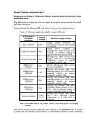
2.0 Supply Application for Load up to 100kVA ......................................................................2<br />
3.0 Supply Application for Load Exceeding 100kVA .............................................................<br />
............................................................. 14<br />
4.0 Application Process for Streetlight ....................................................................................20<br />
CONNECTION GUIDELINES<br />
1.0 Planning for Connection ....................................................................................................22<br />
2.0 Planning and Design Criteria .............................................................................................29<br />
3.0 Demand Estimation ...........................................................................................................42<br />
4.0 Supply Schemes .................................................................................................................44<br />
METERING GUIDELINES<br />
1.0 General ............................................................................................................................51<br />
2.0 Single Phase Metering .......................................................................................................51<br />
3.0 Three Phase Whole Current Metering ...............................................................................54<br />
4.0 Group Metering For Whole Current Metering ..................................................................55<br />
5.0 LVCT Metering ..................................................................................................................56<br />
6.0 Medium and High Voltage Metering .................................................................................58<br />
GLOSSARY AND DEFINITIONS ...........................................................................................63<br />
APPENDIX .................................................................................................................................69<br />
TENAGA<br />
NASIONAL B E R H A D
CONTENTS<br />
1.0 TENAGA NASIONAL BERHAD ELECTRICITY SYSTEM.......................................5<br />
1.1 Introduction ..........................................................................................................................5<br />
1.2 Distribution Division ...........................................................................................................5<br />
1.3 Kedai <strong>Tenaga</strong> .......................................................................................................................6<br />
1.4 Voltages ...............................................................................................................................7<br />
1.5 Supply Frequency ................................................................................................................7<br />
1.6 Earthing System ...................................................................................................................7<br />
1.7 Short Circuit Ratings ...........................................................................................................7<br />
1.8 Act, Regulation and Code ....................................................................................................8<br />
1.9 Supply Voltage Options .......................................................................................................8<br />
1.10 Types of Supply Application ...............................................................................................9<br />
1.11 Consumer Standby Supply ..................................................................................................9<br />
1.12 Alternative Source of Supply ..............................................................................................9<br />
1.13 Provision of Temporary Supply ........................................................................................0 10<br />
1.14 Single Tenant Premise .......................................................................................................0 10<br />
1.15 Multi Tenanted Premises ...................................................................................................0 10<br />
1.16 Turnkey Projects ...............................................................................................................0<br />
...............................................................................................................10<br />
1.17 Connection Charges...........................................................................................................10<br />
1.18 Tariff ..................................................................................................................................<br />
..................................................................................................................................11<br />
1.19 Request for Additional or Special Features .......................................................................<br />
.......................................................................11<br />
1.20 Service Level Agreement (SLA) .......................................................................................11<br />
.......................................................................................<br />
2.0 SUPPLY APPLICATION FOR LOAD UP TO 100kVA ........................................... 12<br />
2.1 Purpose ..............................................................................................................................<br />
..............................................................................................................................12<br />
2.2 What the Applicant Should Do ..........................................................................................12<br />
..........................................................................................<br />
2.3 What the Electrical Contractor Should Do ........................................................................<br />
........................................................................12<br />
2.4 TNB Supply Lead Time ....................................................................................................<br />
....................................................................................................13<br />
2.5 Dispute Between Applicant and Electrical Contractor ......................................................13<br />
......................................................<br />
3.0 SUPPLY APPLICATION FOR LOAD EXCEEDING 100kVA ..............................14<br />
3.1 Purpose ..............................................................................................................................<br />
.............................................................................................................................. 14<br />
3.2 Application Process ...........................................................................................................<br />
........................................................................................................... 14<br />
3.3 Application Parts ...............................................................................................................<br />
............................................................................................................... 14<br />
Part A : Authorities Approval Process .............................................................................<br />
............................................................................. 14<br />
Part B : TNB Technical & Financial Approval Process ...................................................5 15<br />
3.4 What The Applicant Should Do ........................................................................................6 16<br />
3.5 Supply Project Lead Time .................................................................................................7 17<br />
3.6 What The Electrical Consultant Engineer Should Do .......................................................8 18<br />
3.7 Dispute Between Applicant and Electrical Consultant Engineer ......................................9 19<br />
4.0 APPLICATION PROCESS FOR STREETLIGHT ....................................................20<br />
4.1 Purpose ..............................................................................................................................0 20<br />
4.2 Types of Applications ........................................................................................................0 20<br />
4.3 Application by Developer ..................................................................................................0 20<br />
4.4 Application by Individuals/ Local Authority/Government Authority ...............................20<br />
<br />
TENAGA<br />
NASIONAL B E R H A D
1.0 TENAGA NASIONAL BERHAD ELECTRICITY SYSTEM<br />
1.1 Introduction<br />
The <strong>Tenaga</strong> <strong>Nasional</strong> <strong>Berhad</strong> (TNB), a public listed company registered under Companies Act 1965, is charged<br />
with the following responsibilities<br />
• To generate, transmit, distribute and sell energy to consumer throughout Peninsular Malaysia.<br />
• To plan, install, operate and maintain electricity installation for the generation, transmission and distribution<br />
of electricity.<br />
To achieve the above objectives, the company owns and operate power plants and the National Grid, and<br />
installed for this purpose, consumer service centres, call management centres, substations and administrative<br />
offices throughout Peninsular Malaysia. TNB’s core activities are in generation, transmission and distribution<br />
of electricity which are being handled by 3 Divisions :<br />
• Generation Division<br />
• Transmission Division<br />
• Distribution Division<br />
1.2 Distribution Division<br />
Distribution Division supplies electricity in strict accordance with the provisions of the Electricity Supply Act<br />
1990, the Licensee Supply Regulations 1990 and the Electricity Regulations 1994 (and all amendments thereto).<br />
Distribution Division is divided into 2 main regional operational areas where operational efficiency is further<br />
enhanced through the creation of 2 main regional areas, headed by the respective Senior General Managers<br />
which covers :<br />
Area<br />
Region 1<br />
Region 2<br />
States<br />
Selangor, Wilayah Persekutuan, Putrajaya/Cyberjaya,<br />
Negeri Sembilan, Melaka and Johor<br />
Perlis, Kedah, Pulau Pinang, Perak,<br />
Pahang, Terengganu and Kelantan<br />
The States are comprised of main jurisdiction areas under the care of Area Managers. Some areas have smaller<br />
jurisdiction areas and are managed by Branch Managers. All district offices (areas and branches) have one or<br />
more Kedai <strong>Tenaga</strong> under their jurisdiction.<br />
Kedai <strong>Tenaga</strong> provides functions pertaining to Application for Supply, Billing & Collection, Upgrading of<br />
Services and other consumer related activities.<br />
The technical aspects of the operations of the areas include planning, designing, construction, and system<br />
operation and maintenance that delivers supply to the Consumer.<br />
The support departments at the headquarters include Finance, Engineering, Human Resource Management,<br />
Materials Resource Management, Strategic Management and Organisational Development and Consumer<br />
Services and Marketing.<br />
TENAGA<br />
NASIONAL B E R H A D
1.3 Kedai <strong>Tenaga</strong><br />
Kedai <strong>Tenaga</strong> is TNB’s Service and Advisory Centre. It provides TNB’s consumers with Consumer Service<br />
and Elektrik Bestari, TNB’s first branded service that provides electricity advisory service for the home. There<br />
are 145 Kedai <strong>Tenaga</strong> centres throughout Peninsular Malaysia at your service. Please refer to Appendix 1 for<br />
complete information on Kedai <strong>Tenaga</strong> centres throughout Peninsular Malaysia. This list is subject to changes<br />
and may be reviewed from time to time.<br />
Kedai <strong>Tenaga</strong> is where TNB as a caring and friendly utility touches base with its consumers. At Kedai <strong>Tenaga</strong>,<br />
you may experience directly our value-added services which we have specially made available to you, our<br />
valued consumers. Services provided at Kedai <strong>Tenaga</strong> include:<br />
a) One stop payment counter for all electricity and other utility bills.<br />
• Come and meet our friendly personnel who will handle all your utility bills transactions.<br />
Payment can be made by cash, cheque or credit card.<br />
• You can also make arrangements to have your electricity bills paid through banks or<br />
ATM cards.<br />
• TNB, being a caring company, is always concerned about elderly and handicapped consumers<br />
who have genuine problems in settling their bills due to financial difficulties. TNB is aware of<br />
the difficulties encountered and special arrangements can be made for easy payment schemes<br />
for this group of people.<br />
b) Electricity supply application<br />
• At Kedai <strong>Tenaga</strong>, we offer you advice on all matters pertaining to your supply application.<br />
• For wiring purposes in your house, you may choose from a varied selection of contractors<br />
from our directory of registered electrical contractors. This directory enables you to select a<br />
contractor who is base close to your home. It ensures further efficiency and convenience.<br />
• We help you to find out the requirements for supply application in your home.<br />
c) Inquiries pertaining to billing and others.<br />
• Come and visit us to discuss or obtain further clarification on any billing inquiries that you<br />
have. Our front line staff will be happy to help you in resolving any problems you might have<br />
with these inquiries.<br />
d) TNB also offers the following services to its valued consumers:<br />
• Appointments to have the meter read in case the premises are locked during working hours.<br />
• Meter change if consumers suspect that the meter is faulty. If a consumer feels that the meter is<br />
not recording accurately, a written application should be submitted to have the meter tested. A<br />
fee of RM5 will be charged. However, if upon testing the meter it is found that the inaccuracy<br />
is more than 3%, the meter will be replaced and the testing fee of RM5 will be refunded.<br />
• Reconnection of supply to consumers’ premises if the supply is disconnected due to change of<br />
tenancy (if the premises have been vacant for more than 2 months) or nonpayment bill. For<br />
disconnection due to nonpayment of electricity bills, outstanding balances need to be paid<br />
before electricity supply can be reconnected.<br />
• Disconnection of supply if there is a change of tenancy.<br />
<br />
TENAGA<br />
NASIONAL B E R H A D
e) Elektrik Bestari<br />
TNB provides electricity advisory for the home. Our Kedai <strong>Tenaga</strong> has an Elektrik Bestari corner which provides<br />
consumers with basic information on energy efficiency, safety and related topics. For enquiries on electricity<br />
advisory, consumers may enquire at any nearest Kedai <strong>Tenaga</strong>.<br />
1.4 Voltages<br />
The transmission voltage networks are 500kV, 275kV and 132kV, whilst the distribution voltages are 33kV,<br />
11kV and 415/240 Volts. However, in the case of certain parts of Johor & Perak the distribution voltages may<br />
also include 22kV and 6.6kV.<br />
1.5 Supply Frequency<br />
The supply frequency is 50Hz ± 1%.<br />
1.6 Earthing System<br />
High Voltage and Extra High Voltage<br />
• 3 phase configuration<br />
• solidly earthed or impedance earthed<br />
• overhead lines and underground cable are used extensively for high and extra high voltage distribution<br />
Low Voltage 415/240V<br />
• 3 phase 4 wire system<br />
• neutral point solidly earthed mixture of overhead lines, underground cables and aerial insulated cables<br />
• mixture of overhead lines, underground cables and aerial insulated cables<br />
1.7 Short Circuit Ratings<br />
As a guide, the maximum fault levels for the various voltage systems are as follows. All equipment proposed to<br />
be installed and connected to TNB supply must comply with the stated short circuit ratings:<br />
System<br />
Short circuit rating for 3s<br />
i. 500kV 50 kA<br />
ii. 275kV 40 kA<br />
iii. 132kV 31.5 kA<br />
iv. 66kV 20 kA<br />
v. 33kV 25 kA<br />
vi. 22kV 20 kA<br />
vii. 11kV 20 kA<br />
viii. 6.6kV <br />
20 kA<br />
ix. 415/240 V 31.5 kA<br />
TENAGA<br />
NASIONAL B E R H A D
1.8 Act, Regulation and Code<br />
The electricity supply and installation practice in Peninsular Malaysia are governed by the following :-<br />
1 Electricity Supply Act 1990 – Act 447<br />
2 Licensee Supply Regulations 1990<br />
3 Electricity Regulations, 1994<br />
4 Occupational, Safety & Health Act 1994<br />
5 Malaysian Standard MS IEC 60364 Electrical Installation of Buildings<br />
1.9 Supply Voltage Options<br />
Supply may be provided at any of the declared voltages :-<br />
275 kV, 132kV, 33kV, 22 kV*, 11kV, 6.6 kV* and 415/240V. Generally, supplies to domestic premises are<br />
given at single phase 2-wire or three phase 4-wire. However, the actual supply voltage provided depends on the<br />
magnitude of the individual applicant’s load requirements :-<br />
Low Voltage<br />
i. Single-phase, two-wire, 240V, up to 12 kVA maximum demand<br />
ii. Three-phase, four-wire, 415V, up to 45 kVA maximum demand<br />
iii. Three-phase, four-wire, C.T. metered, 415V, up to 1,000 kVA maximum demand<br />
Medium Voltage & High Voltage<br />
i. Three-phase, three-wire and 11kV for load of 1,000 kVA maximum demand and above<br />
ii. Three-phase, three-wire, 22kV or 33kV for load of 5,000 kVA maximum demand and above<br />
iii. Three-phase, three-wire, 66kV, 132kV and 275kV for exceptionally large load of above 25 MVA maximum<br />
demand<br />
It should be noted that voltages other than the above classifications couldn’t be provided by TNB. However,<br />
consumers can make their own transformation arrangements where necessary.<br />
∗ System for certain parts of Johor and Perak only.<br />
<br />
TENAGA<br />
NASIONAL B E R H A D
1.10 Types Of Supply Application<br />
All new applications and upgrade of supply requirement can be classified into three (3) types of supply<br />
applications.<br />
1) Supply Application For Load Up To 100kVA<br />
• Supply usually from existing supply mains<br />
• Submission of applications to TNB by Electrical Contractor registered with the Energy Commission<br />
• Connection of supply may take a maximum of 3 weeks upon approval from the local authorities<br />
2) Supply Application For Load Exceeding 100kVA<br />
• Supply may require establishment of new substation/substations<br />
• Submission of applications to TNB by Consultant Engineer<br />
• Connection of supply may take a minimum of 6 months depending on the extent of electrical infrastructure<br />
required and approval from the local authorities<br />
3) Supply Application For Streetlight<br />
• Application made by the local authority/government department<br />
• Application by developer<br />
• Application by individual<br />
For any supply involving co-generating, a separate licence need to be obtained from the relevant governing<br />
authority.<br />
1.11 Consumers Standby Supply<br />
Standby generator(s) may be used by the applicant at their premises, subject to compliance with the relevant<br />
laws. The generators shall remain a separate system from TNB distribution system and the applicant shall<br />
declare to TNB on the safe installation of the generator(s).<br />
This may be used in place of TNB’s supply source through a suitable, approved changeover facility under<br />
emergency conditions. The Energy Commission and other relevant authorities govern the generators and standby<br />
supply.<br />
1.12 Alternative Source of Supply<br />
A large consumer may require an alternative source of supply. TNB will provide such alternative supply at an<br />
additional cost.<br />
<br />
TENAGA<br />
NASIONAL B E R H A D
1.13 Provision Of Temporary Supply<br />
Temporary supply can be installed for a period of 6 months. Supply is intended for purposes of electric supply for<br />
temporary work site, festivals and celebrations. The applicant shall provide a suitable corridor for installation of<br />
supply mains and site for metering point. The meter will be installed at a meter board provided by the applicant.<br />
The Electrical Contractor shall test the installation.<br />
If the requirement exceeds 6 months, the approval shall be subject to availability of supply<br />
Application for temporary supply shall be separately submitted, stating the load requirements. The applicant<br />
will be charged full cost and according to the appropriate tariff plus an additional 33% surcharge on the total<br />
monthly bill.<br />
1.14 Single Tenant Premises<br />
If the supply is for a single tenant only (the owner, the developer or the landlord) then the entire supply will<br />
be metered at the applicant’s incoming switchboard. The consumption will be charged at the appropriate tariff<br />
rates.<br />
1.15 Multi Tenanted Premises<br />
If the supply is for multi tenanted premises where part of the supply is intended for the owner, developer or<br />
landlord, and the rest for the tenants in the building, the landlord’s supply and each of the tenant’s supplies will<br />
be separately metered and billed by TNB.<br />
The owner, developer, or landlord shall provide, own, maintain and repair at his own expense the electrical<br />
systems in the buildings including adequate and necessary rising and lateral mains. The design, installation and<br />
operating of such electrical systems shall comply with requirements of all the relevant authorities including the<br />
Energy Commission’s and TNB’s.<br />
1.16 Turnkey Projects<br />
In certain cases, the applicant may apply to undertake the planning and installation of the electrical systems<br />
(including overhead lines, switchgears, cables, based on TNB’s specifications and requirements) with the<br />
assistance of Electrical Consultant Engineer(s) and Electrical Contractor(s). Under the ‘turnkey’ concept the<br />
applicant will then hand over the entire electrical system to TNB. A separate discussion on this will have to be<br />
conducted with TNB.<br />
1.17 Connection Charges<br />
Please refer to the Statement of Connection Charges booklet available at the Kedai <strong>Tenaga</strong>. The booklet is<br />
subjected to change as may be published from time to time.<br />
10 TENAGA<br />
NASIONAL B E R H A D
1.18 Tariff<br />
Please refer to the Tariff booklet available at the Kedai <strong>Tenaga</strong>. Tariffs are subjected to change as may be<br />
published from time to time and approved by the Minister of Energy, Water and Telecommunication<br />
1.19 Request For Additional Or Special Features<br />
Any request for additional or special features eg special request for an additional feeder by applicant, the<br />
applicant will have to pay the full cost of the additional request.<br />
1.20 Service Level Agreement (SLA)<br />
Offer is open to all housing developers to enter into a Service Level Agreement (SLA) with TNB when applying<br />
for electricity supply for housing development (as prescribed under the Housing Development (Control and<br />
Licensing) Act 1966). The scope of the SLA includes the time frame process for connection of supply and the<br />
duties and obligation by TNB and housing developers in ensuring the electricity supply is connected to the<br />
housing projects within the stipulated time to avoid delays in handing over houses to the purchaser.<br />
Please refer to the Kedai <strong>Tenaga</strong> for details on the SLA.<br />
11<br />
TENAGA<br />
NASIONAL B E R H A D<br />
11
2.0 SUPPLY APPLICATION FOR LOAD UP TO 100kVA<br />
2.1 Purpose<br />
The application for the supply of electricity with load up to 100kVA which is for a 3 phase low voltage system<br />
is outlined here.<br />
2.2 What The Applicant Should Do<br />
The applicant should take the following steps to apply for supply of electricity up to 100kVA for a 3-phase<br />
low voltage system.<br />
Steps Action Reference<br />
1<br />
Appoint an Electrical Contractor who is registered with The Energy<br />
Commission, who will act on their behalf and submit the application for the<br />
applicant using the Supply Application Form available at Kedai <strong>Tenaga</strong>.<br />
The Electrical Contractor must be<br />
registered with the Energy Commission<br />
2 Settle connection charges billed by TNB through the Electrical Contractor<br />
Statement of Connection Charges<br />
booklet available at any Kedai <strong>Tenaga</strong><br />
3<br />
After completion of TNB’s work (before installation of meter), the<br />
applicant shall:<br />
• Deposit a sum of money equivalent to 2 months bill or as reviewed from<br />
time to time. For deposit of more than RM2,000, the applicant can settle<br />
either in cash or Bankers Guarantee<br />
• Sign electricity supply contract with TNB through the appointed<br />
Electrical Contractor<br />
Tariff booklet available at the nearest<br />
Kedai <strong>Tenaga</strong><br />
2.3 What The Electrical Contractor Should Do<br />
The Electrical Contractor appointed by the applicant should take the following action:<br />
Steps Action Reference<br />
1 Submit application for the applicant using the Supply Application Form<br />
available at Kedai <strong>Tenaga</strong>.<br />
All documents in checklist must be completed, duly endorsed by the<br />
appropriate competent person(s) of the appropriate category and attached<br />
with the application.<br />
Appendix 3<br />
2 After TNB has :<br />
• validated compliance to checklist<br />
• conducted analysis of supply connection<br />
• reviewed connection charges and issue bill to contractor<br />
Statement of Connection<br />
Charges Booklet available<br />
at any Kedai <strong>Tenaga</strong><br />
The applicant shall settle connection charges to TNB.<br />
3 After TNB has implemented work on site, the Electrical Contractor shall:<br />
• Submit G and H form certifying the internal installations<br />
have been tested<br />
• Arrange for applicant to sign supply contract with TNB<br />
• Arrange appointment for meter installation with TNB<br />
Tariff Booklet available at nearest<br />
Kedai <strong>Tenaga</strong><br />
12 TENAGA<br />
NASIONAL B E R H A D
2.4 TNB Supply Lead Time<br />
The flowchart for the application process is as outlined in Appendix 2. TNB supply lead-time will take up to 3<br />
weeks depending on the approval from the local authorities.<br />
2.5 Dispute Between Applicant And The Electrical Contractor<br />
In the event of a dispute between the applicant and the Electrical Contractor and the applicant wishes to terminate<br />
the services of the Electrical Contractor, the applicant shall duly notify the Electrical Contractor concerned in<br />
writing with the copy extended to TNB. TNB shall not be a party to any dispute or litigation arising thereof.<br />
13<br />
TENAGA<br />
NASIONAL B E R H A D<br />
13
3.0 SUPPLY APPLICATION FOR LOAD EXCEEDING 100kVA<br />
3.1 Purpose<br />
To explain the process for supply application with load exceeding 100kVA.<br />
3.2 Application Process<br />
The application process incorporates not only TNB requirements but taking into account the Government<br />
Development Plan Approval Process in Peninsular Malaysia (except Wilayah Persekutuan Kuala Lumpur and<br />
Putrajaya) issued by the Bahagian Perancangan Dasar & Pembangunan Kementerian Perumahan dan Kerajaan<br />
Tempatan: 2002 Edition.<br />
The inclusion of the said Government procedure shall ensure :<br />
• Infrastructure planning and approval process of the TNB complements the National Policy<br />
• TNB as a member Agency of the Government Development Plan Committee has to ensure complete<br />
transparency of its process through timely responses to Development Plan Approval Process<br />
• TNB Supply Application Process ensures complete agreement of Distribution Division’s plans and the<br />
Consultant Engineers submissions especially on the location and size of substations needed for the supply<br />
of electricity to the development area, and is valid for 2 years after the approval from the Jabatan Perancang<br />
Bandar & Desa (JPBD).<br />
3.3 Application Parts<br />
There are two parts to the application :<br />
Part Function Reference<br />
A Requirement of Approval from the Government’s Development Plan Approval Process Appendix 4 & 5<br />
B TNB Application Requirement after completion of Part A Appendix 7<br />
PART A : Authorities Approval Process<br />
The part A process approval that involves TNB’s technical comments is as shown in Development Plan Approval<br />
Process in Appendix 4 & 5. At each application process, TNB requires a processing time of up to 10 days to<br />
complete the comments for Jabatan Perancang Bandar & Desa (JPBD). The main process can be summarised<br />
as follows :<br />
Stage<br />
Description<br />
1 Submit Development Plan<br />
The Consultant Engineer submits development plan application for the proposed development to JPBD.<br />
All plans must be prepared by a licensed surveyor.<br />
The comments from all relevant technical agencies including TNB are required prior to approval by JPBD.<br />
14 TENAGA<br />
NASIONAL B E R H A D
Stage<br />
Description<br />
2 TNB Register Application<br />
The Consultant Engineer/JPBD submits application to TNB complete with required details as in Checklist<br />
in Appendix 6. TNB will:<br />
• Acknowledge receipt and gives a file number, which is used as reference in any dealings with TNB.<br />
Study the proposal. Match the existing system network and determine method of supply.<br />
3 Mutual Understanding Of Plan<br />
Both TNB and Consultant Engineer will conduct discussion to agree to technical requirement such as<br />
substation number, size, location, site and consumers main switch room.<br />
In case of a dispute on TNB proposal, the Consultant Engineer shall refer to the relevant State General<br />
Managers. A discussion shall be arranged by the relevant State General Managers to arrive at an agreement.<br />
4 TNB Submit Comments to JPBD<br />
TNB submit to JPBD the proposed development plans including all technical comments using TNB official<br />
stamp as required by JPBD.<br />
JPB approves the proposed development plan. The validity is subjected to:<br />
- confirmation of layout details and precomputation plans<br />
- no changes in development<br />
- 2 years extension<br />
5 TNB Application for Electricity Supply above 100KVA process starts<br />
(Part B)<br />
PART B : TNB Technical & Financial Approval Process<br />
Part B process is the TNB Application Process for Electricity Supply above 100 KVA as outlined in Appendix<br />
7. The process starts after the completion of Part A (Authorities Approval Process). The Process in Part B can<br />
be summarised as follows:<br />
Stage<br />
1 Submit Application<br />
Description<br />
The Electrical Consultant Engineer submits application for the Electricity Supply to the nearest Kedai<br />
<strong>Tenaga</strong>. Complete details as in Appendix 6 must be submitted with the application.<br />
TNB will issue an acknowledgement letter to the Electrical Consultant Engineer as in Appendix 8 using the<br />
same file reference given during Part A (Authorities Approval Process).<br />
2 Documentation Check And System Study<br />
TNB will advise on the necessary amendment 15 to the consultant by telephone or letter. The Electrical<br />
Consultant Engineer is to ensure that all the amendments are done and resubmitted to TNB.<br />
TENAGA<br />
NASIONAL B E R H A D<br />
15
Stage<br />
3 Joint Meeting<br />
Description<br />
TNB will restudy the amendments and arrange for a joint meeting with the Electrical Consultant Engineer<br />
for final acceptance of the technical requirements. Activities of both parties will be recorded in the Joint<br />
Meeting Action Log as in Appendix 9.<br />
4 Connection Charges<br />
TNB will issue a Notice of Connection Charges to the Electrical Consultant Engineer as per Appendix 10.<br />
5 Electricity Infrastructure Agreement (Optional)<br />
The applicant may decide to enter into an Electricity Infrastructure Agreement with TNB with regard to<br />
TNB scope of work, charges and timely connection.<br />
6 Discussion And Preparation Of Site Work<br />
After payment of connection charges, the Electrical Consultant Engineer will arrange for pre start work<br />
discussion and site and substation building hand over.<br />
7 Construction Completion And Substation Energising<br />
TNB will manage the construction work and is responsible for the commissioning of substations. The<br />
energising of supply by TNB will normally be done at the same time as the installation of the meters. For<br />
HV supply, the supply shall be energised in the presence of the Electrical Consultant Engineer and for LV<br />
consumers in the presence of the Electrical Contractor.<br />
8 Supply Application By The Electrical Contractor<br />
The Consultant Engineer advises the Electrical Contractor to submit supply application for load requirement<br />
up to 100kVA, normally for individual applicant. The process is the same as outlined in Section 2.<br />
3.4 What The Applicant Should Do<br />
The applicant should take the following action in applying for supply application for load exceeding<br />
100KVA.<br />
Steps Action Reference<br />
1 • Appoint one () Electrical Consultant Engineer for each supply application<br />
Appendix 11<br />
• Submit an appointment letter of the Electrical Consultant Engineer allowing him<br />
to act on behalf of the applicant to TNB.<br />
16 TENAGA<br />
NASIONAL B E R H A D
Steps Action Reference<br />
2 After approval from JPBD and TNB completion of work plan, the applicant settles<br />
connection charges to TNB at any Kedai <strong>Tenaga</strong>.<br />
The applicant may decide to enter into an Electricity Infrastructure Agreement with<br />
TNB with regard to TNB scope of work, charges and timely connection.<br />
Statement of<br />
Connection Charges<br />
Booklet available at<br />
Kedai <strong>Tenaga</strong><br />
3 • Provide the substation(s) land and building(s) to TNB by:<br />
- Leasing the substation land at a nominal value of RM10.00 to TNB, or<br />
- Transfer the substation land at a nominal value of RM10.00 to TNB<br />
• The Certificate of Fitness of the substation building/compartment shall be<br />
handed to the TNB.<br />
Statement of<br />
Connection charges<br />
booklet available at<br />
Kedai <strong>Tenaga</strong><br />
The transfer of the land title should be finalised prior to the handing over of site.<br />
In the absence of the land title, the applicant is to prepare a Bank Guarantee for<br />
TNB for the period of twelve () months and shall be renewed until the land title is<br />
transferred to TNB or registration of lease to TNB<br />
Delay in title transfer may affect project implementation. TNB have the right to use<br />
the substation to supply electricity to other consumers.<br />
4 Applicants are required to:<br />
• Deposit a sum of money equivalent to 2 months bill or as reviewed from time to<br />
time. For deposit of more than RM 2,000, the applicant can settle either in cash<br />
or Bankers Guarantee.<br />
• Sign electricity supply contract with TNB through the appointed Electrical<br />
Contractor.<br />
3.5 Supply Project Lead Time<br />
The lead-time for supply connection depends on a number of factors including the type of premises, the electrical<br />
load required and the location of the premises and approval of the local authorities.<br />
Applicants should submit their applications for supply as early as possible giving the necessary information of<br />
their requirements to the nearest Kedai <strong>Tenaga</strong>. They must also inform TNB of the progress of their project(s).<br />
The above measures are necessary to ensure that TNB’s supply projects are coordinated with the construction<br />
and wiring installation at the applicants’ premises, and thus avoid any delay in connection of supply. The typical<br />
supply project lead time required by TNB is as follows:<br />
17<br />
TENAGA<br />
NASIONAL B E R H A D<br />
17
Requirement<br />
Supply Project Typical Lead Time<br />
132 kV and above 3 years – 5 years<br />
33 kV 18 months - 2 years<br />
11 kV 6 months – 12 months<br />
415 V and below Less than 6 months<br />
3.6 What The Electrical Consultant Engineer Should Do<br />
The Electrical Consultant Engineer plays a major role to represent the applicant and ensure compliance with<br />
other relevant government departments and TNB. The Electrical Consultant Engineer is advised to observe the<br />
steps as outlined below:<br />
Steps<br />
1<br />
Action<br />
• Submits application for the proposed development to JPB and TNB<br />
• All plans must be prepared by a Licensed Surveyor<br />
Liaise with TNB to come up with a mutual understanding of plan and to get approval by JPBD<br />
Submits application for the electricity supply to Kedai <strong>Tenaga</strong>.<br />
Complete details as outlined in Appendix 6 and 12 must be submitted with the application. The application must be<br />
accompanied by 3 copies of the following :-<br />
2<br />
i) Location plan<br />
ii) Site plan showing the lot number(s)<br />
iii) The plan of the proposed substation (when relevant)<br />
iv) The proposed electrical wiring system designs<br />
v) The proposed consumer’s switchroom (where applicable)<br />
vi) The approval of the building plans by the relevant Authorities<br />
• Clearly state details of the applicants supply requirements.<br />
Provide a comprehensive description of the proposed development and a list including all detail of the connected<br />
loads, motors/appliances, the associated ratings, type of motor starter and their arrangements (where applicable).<br />
• Submit the metering requirements for CT Meters as in Appendix 20.<br />
3 Ensure that all the amendments are complied with and resubmitted to TNB.<br />
4<br />
5<br />
• Ensure that the applicants main switchroom shall be located adjoining the TNB’s substation or as mutually agreed<br />
to be most appropriate under the specific design<br />
• Provide appropriate cable trenching from the TNB’s substation to the main switchroom and a panel/cubicle for<br />
metering or a free standing meter cubicle in the case of high voltage installation in the consumer’s switchroom or<br />
substation<br />
• Ensure that consumer switchgears, control gears, transformers, relay panels, switchboards, metering current<br />
transformer, potential transformer etc. to be connected to TNB’s system must be approved by the Energy<br />
Commission.<br />
• Appoint an Electrical Contractor for wiring up the premises<br />
• Provide installation test results and protection settings for all CT metered applicants.<br />
6 Ensure that the wiring and the installation work of applicant’s equipment shall be supervised by competent person(s).<br />
18 TENAGA<br />
NASIONAL B E R H A D
Steps<br />
7<br />
8<br />
Action<br />
Advise applicant to submit application form through registered Electrical Contractor. The process is the same as outlined<br />
in Section 2.<br />
Advise applicant to deposit a sum of money equivalent to 2 months bill or as reviewed from time to time. For deposit of<br />
more than RM2,000 the applicant can settle either in cash or Bankers Guarantee.<br />
3.7 Dispute Between Applicant And Electrical Consultant Engineer<br />
In the event of a dispute between the applicant and the Electrical Consultant Engineer and the applicant wishes<br />
to terminate the services of the Electrical Consultant Engineer, the applicant shall duly notify the Electrical<br />
Consultant Engineer concerned in writing with the copy extended to TNB. TNB shall not be a party to any<br />
dispute or litigation arising thereof.<br />
19<br />
TENAGA<br />
NASIONAL B E R H A D<br />
19
4.0 Application Process for Streetlight<br />
4.1 Purpose<br />
This procedure outlines the process for the application for streetlight.<br />
4.2 Types of Applications<br />
The three () types of application for streetlights are:<br />
• Application made by the local authority/government authority<br />
• Application by developer<br />
• Application by individual<br />
4.3 Application by Developer<br />
The local authority or developer should take the following steps to apply for streetlight.<br />
Steps<br />
Action<br />
1 Appoint a Consultant Engineer and an Electrical Contractor that is registered with the Energy<br />
Commission.<br />
2 The application is made together with the supply application for a new housing development with<br />
all the load details of the proposed public lighting that is approved by the local authority.<br />
4.4 Application By Individuals/Local Authority/Government Authority<br />
The application process is similar for both individuals and local authority or government authority. Individuals<br />
must already have an account with TNB. The installation of streetlight depends on:<br />
• Installation of streetlight on existing TNB pole<br />
• Installation involving additional poles<br />
IF<br />
Installation of streetlight on existing<br />
TNB pole<br />
Installation involving<br />
additional poles<br />
THEN<br />
Consumer submits application to the Kedai <strong>Tenaga</strong>.<br />
The applicant settles the full cost of additional new pole/poles<br />
installed.<br />
20 TENAGA<br />
NASIONAL B E R H A D
CONTENTS<br />
Page<br />
<br />
1.0 PLANNING FOR CONNECTION ......................................................................................... 22<br />
1.1 Declaration Of Loads And Its Characteristics ............................................................................ 22<br />
1.1.1 Supplies at 415V and 240V .............................................................................. 22<br />
1.1.1.1 Technical Requirements For Connection ............................................ 23<br />
1.1.2 Supplies at 275kV, 132kV, 33kV, 22kV, 11kV and 6.6kV ............................... 23<br />
1.1.3 Supplies To Embedded / Distributed Generators ............................................. 24<br />
1.1.3.1 Planning Data Requirements For Connection of Embedded /<br />
Distributed Generators......................................................................... 24<br />
1.1.3.2 Pre-connection Studies For Embedded / Distributed Generators ....... 27<br />
1.2 Other Information Requirements .................................................................................. 28<br />
2.0 PLANNING AND DESIGN CRITERIA ............................................................................... 29<br />
2.1 Steady-State Supply Voltage Performance .................................................................... 29<br />
2.2 Supply Security Level ................................................................................................... 29<br />
2.2.1 Adopted Security Level Definitions For TNB Distribution System ................ 30<br />
2.2.2 Supply Security Level to Consumers ............................................................... 30<br />
2.2.3 Request For Higher Supply Security Level ..................................................... 30<br />
2.3 Power Quality ............................................................................................................... 30<br />
2.3.1 Power Quality Requirements ........................................................................... 30<br />
2.3.2 Scope ................................................................................................................ 31<br />
2.3.3 Voltage Dips/Sags ............................................................................................ 31<br />
2.3.4 Voltage Step Change ........................................................................................ 32<br />
2.3.5 Voltage Fluctuations and Flicker ..................................................................... 33<br />
2.3.6 Harmonics ........................................................................................................ 35<br />
2.3.7 Voltage Unbalance ........................................................................................... 38<br />
2.4 Short-Circuit Levels ...................................................................................................... 39<br />
2.5 Protection Requirements ............................................................................................... 40<br />
2.5.1 Basic Requirements .......................................................................................... 40<br />
2.5.2 Specific Requirement ........................................................................................ 40<br />
2.5.3 Protection System Evaluation Process ............................................................. 41<br />
3.0 DEMAND ESTIMATION ........................................................................................... 42<br />
3.1 Demand Estimates For Consumer Sub-Classes Or Premises ........................................ 42<br />
3.2 Group Diversity ............................................................................................................. 43<br />
3.3 Demand Estimates For A Mixed Development Area .................................................... 43<br />
3.4 Demand Projection And Substation Requirements For LV Scheme ............................. 43<br />
4.0 SUPPLY SCHEMES.................................................................................................................. 44<br />
4.1 Maximum Demand Levels And Supply Schemes ......................................................... 44<br />
4.2 Substation Categories, Type & Design .......................................................................... 44<br />
4.2.1 Sub-Station Categories ..................................................................................... 44<br />
4.2.2 Land Or Building Size Requirements For Sub-Station .................................... 46<br />
4.2.3 Type Of Fire Fighting System For The Sub-Station ......................................... 47<br />
4.3 Standard And Special Feature Design Schemes ............................................................ 47<br />
4.4 Supply Schemes For Interconnection To Embedded Generators .................................. 47<br />
TENAGA<br />
NASIONAL B E R H A D<br />
21
SECTION 1: PLANNING FOR CONNECTION<br />
Sets of data and information are to be furnished by Electrical Contractors and Electrical Consultant Engineers acting on<br />
behalf of consumers or developers at the time of application of supply and prior to connection of supply.<br />
Based upon submitted data and information, TNB will plan for the connection system to satisfy the planning and design<br />
criteria and use the best engineering practices to ensure reasonable cost of equipment, materials and workmanship as<br />
well as reasonable time period for connection of supplies.<br />
1.1 DECLARATION OF LOADS AND ITS CHARACTERISTICS<br />
TNB requires adequate information on magnitude and characteristics of the loads to be consumed by consumer or<br />
installation.<br />
1.1.1 Supplies at 415V and 240V<br />
For supplies at Low Voltages of 240V and 415V, the Consumer shall, in the appropriate application forms for<br />
connection obtainable from TNB provide the following data.<br />
(a) Maximum power requirements in kVA;<br />
(b) Types and number of equipment and its corresponding connected capacity in kVA;<br />
(c) Shunt connected reactors and capacitors in kVAr;<br />
(d) The date when connection is required;<br />
(e) For single-phase 240V motors with rating of greater than 6kVA and/or three-phase 415V motors<br />
with rating greater than 75kVA, the following information shall be provided for each motor;<br />
(i) Rating in HP or KVA;<br />
(ii) Types of control equipment;<br />
(iii) Methods of starting and starting current;<br />
(iv) Frequency of starting (number/hour); and<br />
(v) Rated power factor;<br />
(f) Voltage sensitive loads (indicating sensitivity)<br />
Where a preliminary examination of the above data indicates that more detailed information is required, the<br />
consumer shall provide additional information upon request by TNB.<br />
22 TENAGA<br />
NASIONAL B E R H A D
1.1.1.1 Technical Requirements For Connection<br />
For connections at Low Voltage the consumer’s installation shall comply with the Electricity Supply Act 1990<br />
and any regulations made there under and Malaysian Wiring Regulations and any requirements specified by<br />
TNB based on Malaysian MS-IEC Standards.<br />
In the case of connections to Consumers at Low Voltage, TNB has the responsibility to specify any technical<br />
requirements for the connection. This includes specification of technical requirements associated with loads<br />
which may give rise to voltage fluctuations and harmonics.<br />
1.1.2 Supplies at 275kV, 132kV, 33kV, 22 kV, 11kV and 6.6kV<br />
For supplies at voltages of 275kV, 132kV, 33kV, 22kV, 11kV and 6.6kV, the Consumer shall provide comprehensive<br />
information on the loads and their characteristics including but not limited to the following:<br />
a)<br />
For all types of loads:<br />
(i) Maximum Active Power consumption in kW; and<br />
(ii) Maximum Reactive Power consumption in kVAR.<br />
b)<br />
For motor loads:<br />
(i) Types of control equipment;<br />
(ii) Methods of starting;<br />
(iii) Magnitude and duration of the starting current;<br />
(iv) Frequency of starting (number/hour);<br />
(v) Under voltage setting and time;<br />
(vi) Negative phase sequence protection; and<br />
(vii) Sub-transient and/or locked rotor reactance of the motor.<br />
c)<br />
For nonlinear loads with harmonic current injections:<br />
(i) Harmonic current spectrum including harmonic number and the corresponding maximum<br />
current.<br />
d) For fluctuating loads:<br />
(i) The rates of change of Active Power and Reactive Power consumption in kW/minute and<br />
kVAR/minute respectively, both increasing and decreasing;<br />
(ii) The shortest repetitive time interval between fluctuations for Active Power and Reactive Power<br />
in minutes; and<br />
(iii) The magnitude of the largest step changes in Active Power and Reactive Power in kW and<br />
kVAR respectively, both increasing and decreasing.<br />
TENAGA<br />
NASIONAL B E R H A D<br />
23
e)<br />
f)<br />
For voltage sensitive loads:<br />
(i) steady-state voltage tolerance limits of the equipment in percentage of the nominal voltage;<br />
(ii) intrinsic immunity limits to short duration voltage variation;<br />
(iii) transient voltage tolerance limits of the equipment in percentage of the nominal voltage and the<br />
corresponding duration;<br />
(iv) harmonic current emission limit for equipment.<br />
For Shunt Connected Reactors and Capacitors:<br />
(i) configuration and sizes of individual banks;<br />
(ii) types of switching and control equipment; and<br />
(iii) types of harmonic filtering reactors.<br />
Should a preliminary examination of the above data indicate that a more detailed information is required, the<br />
consumer shall provide the information upon request by TNB.<br />
TNB upon receipt of the data and information should perform assessments of the impacts of the loads on<br />
TNB’s distribution system. Consumers shall then be advised on TNB’s design of supply scheme and other<br />
technical requirements to be complied with by the consumers to ensure system performance is within the limits<br />
or standard.<br />
1.1.3 Supplies To Embedded / Distributed Generators<br />
1.1.3.1 Planning Data Requirements For Connection Of Embedded / Distributed Generators<br />
Embedded / distributed generator installations are treated as a different consumer class. For the purposes of planning<br />
the connection of a Distributed Generator to the Distribution System, TNB requires sufficient information to model the<br />
generating plant and carry out engineering studies for determining the method of connection to be employed, the voltage<br />
level of connection and its impacts on the Distribution System. The Distributed Generator shall provide the following<br />
information to TNB for planning purposes.<br />
(a) For all Generating Units<br />
(i) Terminal voltage;<br />
(ii) Rated kVA;<br />
(iii) Rated kW;<br />
(iv) Maximum Reactive Power sent out or minimum lagging power factor;<br />
(v) Maximum Reactive Power absorbed or minimum leading power factor;<br />
(vi) Type of Generating Unit – synchronous, asynchronous, etc.<br />
(vii) Type of prime mover;<br />
(viii) Type of voltage control;<br />
(ix) Generating Unit sub-transient reactance;<br />
(x) Generating Unit transformer details;<br />
(xi)<br />
Requirements for Top-Up Supply and/or Standby Supply.<br />
24 TENAGA<br />
NASIONAL B E R H A D
Should a preliminary examination of the above data indicate that more detailed information is required; the Distributed<br />
Generator shall provide additional information as follows upon request by TNB.<br />
(b) For a Generating Unit with a capacity greater than 3 MW, the following additional information shall be<br />
provided to TNB by the Distributed Generator:<br />
(i) Generating Unit electric and mechanical data (all impedance (unsaturated) in p.u. of rating and time<br />
constants in seconds)<br />
• Type of prime mover<br />
• Rated MVA<br />
• Rated MW<br />
• Generating Unit rotor and turbine moment of inertia or inertia constant<br />
• Generating Unit MW / MVAR capability chart\<br />
• Type of excitation system<br />
• Stator resistance<br />
• Direct-axis sub-transient reactance<br />
• Direct-axis transient reactance<br />
• Direct-axis synchronous reactance<br />
• Quadrature-axis sub-transient reactance<br />
• Quadrature-axis transient reactance<br />
• Quadrature-axis synchronous reactance<br />
• Direct-axis sub- transient open circuit time constant<br />
• Direct-axis transient open circuit time constant<br />
• Quadrature-axis sub-transient open circuit time constant<br />
• Quadrature-axis transient open circuit time constant<br />
• Zero sequence resistance<br />
• Zero sequence reactance<br />
• Negative sequence resistance<br />
• Negative sequence reactance<br />
• Generating Unit open circuit saturation curve<br />
(ii) Generating Unit transformer data<br />
• MVA rating<br />
• % resistance<br />
• % reactance<br />
• Tap range in p.u.<br />
• Tap step in p.u.<br />
• Vector group<br />
• Method of earthing<br />
TENAGA<br />
NASIONAL B E R H A D<br />
25
(iii) Automatic voltage regulator (AVR) data<br />
• A block diagram for model of the AVR including the data in gains, forward and feedback gains,<br />
time constant and voltage control limits and limit characteristics.<br />
(iv) Speed governor and prime mover data<br />
A block diagram for the model of the generating unit speed governor including its control parameters,<br />
time constants, gains, valve limits, temperature controls, deadbands, turbine rating, maximum and<br />
minimum power, penstock parameters, tunnel parameter, surge chamber parameters and all other<br />
relevant data.<br />
Should a preliminary examination of the above data indicate that more detailed information is required;<br />
the Distributed Generator shall provide additional information upon request by TNB.<br />
(c)<br />
For Fixed Speed Asynchronous Induction Generating Units the following data may be required:<br />
• Stator Current at unity power factor<br />
• Stator Current max at lagging power factor<br />
• Stator Current min at lagging power factor<br />
• Magnetizing reactance<br />
• Stator resistance<br />
• Stator reactance<br />
• Inner cage or running rotor resistance<br />
• Inner cage or running rotor reactance<br />
• Outer cage or standstill rotor resistance<br />
• Outer cage or standstill rotor reactance<br />
• For the above state whether derived from inner outer cage or running-standstill measurements<br />
• Slip at rated output per unit<br />
• Load torque-speed coefficient B<br />
• Load torque-speed coefficient C<br />
• Inertia constant for generator prime mover drive chain<br />
Note:<br />
The torque-speed (T-N) relationship is defined as:<br />
T = T 0<br />
(A + BN = CN 2 ) where A = 1.0 – B – C<br />
Therefore only B & C are needed.<br />
Alternatively a per unit torque-speed curve can be provided.<br />
• Describe method of adding star capacitance over the operating range<br />
26 TENAGA<br />
NASIONAL B E R H A D
• Capacitance connected in parallel at % of rated output Starting<br />
20%<br />
40%<br />
60%<br />
80%<br />
100%<br />
• Maximum starting current in Amps<br />
• Starting Regime - Symmetrical RMS current at time t from energisation:<br />
- t = 0 ms<br />
- t = 50 ms<br />
- t = 200 ms<br />
- t = 1 s<br />
- t = 5 s<br />
• The operating chart to show range of reactive import and export with compensation as a function<br />
of Active Power.<br />
• Details of the turbine and governor model, described in block diagram form showing transfer<br />
functions of individual elements<br />
The Distributed Generator will need to provide the above characteristic for each asynchronous<br />
Generating Unit based on the number of pole sets (i.e. Two data sets are required for dual speed 4/6<br />
pole machines).<br />
For large sites, with multiple machines, the Distributed Generator may alternatively provide an equivalent network<br />
modelled as an asynchronous Generating Unit with matching Generating Unit Transformer at the Connection Point. This<br />
equivalent should also model the site electrical network and power factor correction, etc.<br />
Should a preliminary examination of the above data indicate that more detailed information is required; the Distributed<br />
Generator shall provide additional information upon request by TNB.<br />
1.1.3.2 Pre-Connection Studies For Embedded / Distributed Generators<br />
The following pre-connection studies are necessary for the purpose of designing the interconnection facilities for<br />
embedded / distributed generators:-<br />
(i) System studies of embedded / distributed generator installation encompassing load flow, short-circuit,<br />
stability, load rejection or islanding studies and protection coordination studies. The part of preconnection<br />
studies is to be carried by a consultant appointed the owner of embedded / distributed<br />
generator. The associated costs shall be borne by the owner of embedded generator. The results of study<br />
will be presented to TNB for evaluation.<br />
TENAGA<br />
NASIONAL B E R H A D<br />
27
(ii)<br />
TNB upon receiving the above study and other necessary data shall conduct an integrated study of the<br />
interconnected systems. The scope of study will include load flow, short-circuit, stability and protection<br />
coordination studies. The costs of this study will also be borne by the owner of generator seeking<br />
interconnection with the distribution system.<br />
1.2 OTHER INFORMATION REQUIREMENTS<br />
Other sets of information as listed below are necessary for TNBD to plan for connection of supply to consumers.<br />
1. Site plan or location plan (see Appendix ) indicating the geographical position of the premises/buildings<br />
of consumers. This information is essential for TNB to locate TNB’s infrastructure nearest to the prospective<br />
consumers.<br />
2. Layout plan (see Appendix ) for developed/proposed development. This information is necessary for TNB to<br />
locate sub-station locations, if not previously identified, and feeder routes for MV or LV networks. Sketched layout<br />
plans are required for individual or group applications less than 100KVA. Additional information, which needs to<br />
be specified in the supply application form, is the position of prospective consumer with respect to LV system or<br />
sub-station in terms of distance and estimated number of spans of LV feeders.<br />
3. Building layout plans are particularly useful for indicating services entrance location/positions, position of substations<br />
and consumer switch rooms.<br />
4. Sub-station layout plan for both sub-stations integrated into a building or in separate building.<br />
5. Consumer switch room layout indicating location of main switchboard, service cable entry position and necessary<br />
ducting or trenching.<br />
6. Wiring diagrams of installation to be approved and endorsed by Electrical Consultant Engineer for demand greater<br />
than 100kVA. The single line drawing of the installation must encompass the complete installations indicating<br />
incoming switches, main and sub-switchboards, main protection for incoming TNB supply as well as sub-circuit<br />
protection, metering schemes, conductor sizes, major equipment e.g motors etc., standby generators, capacitor<br />
banks. Ratings of switchgears and components must also be indicated.<br />
7. Appendix 14 is the form which registers the consent or acknowledgement of developer/owner for leasing/transfer<br />
of sub-station lot to TNB. This form is to be submitted by Electrical Consulting Engineers, acting on behalf of<br />
consumers, for projects requiring substations.<br />
Appendix 6 is a checklist for reference to consumers, electrical contractors and consultant engineers on range data<br />
or information required at the supply application processing stage.<br />
28 TENAGA<br />
NASIONAL B E R H A D
SECTION 2.0 PLANNING AND DESIGN CRITERIA<br />
TNB in developing the connection system or supply infrastructure needs to satisfy a set of planning and design criteria<br />
which are described in this section.<br />
2.1 STEADY-STATE SUPPLY VOLTAGE PERFORMANCE<br />
(a)<br />
Steady-State Voltage Fluctuation under Normal Condition<br />
Under normal condition, when all circuit elements are in service, the distribution network including<br />
the points before the consumer metering must be planned to be maintained as is table 2-1 below:-<br />
Table 2-1: Steady -state voltage level fluctuation limits under normal conditions<br />
Voltage level<br />
% variation<br />
415V and 240V -10% & +5%<br />
6.6kV, 11kV, 22kV,33kV +/- 5%<br />
132kV and 275kV -5% & +10%<br />
(b)<br />
Steady-State Voltage Fluctuation under Contingency Condition<br />
Under contingency condition, when one or more circuit elements are on outage, the power frequency<br />
steady-state voltage at all points in the distributor’s distribution system including the points before the<br />
consumer metering must be planned to be maintained as follows:<br />
Table 2-2: Steady-State Voltage Fluctuation Limits under Contingency Condition<br />
Voltage level<br />
% variation<br />
415V and 240V +/- 10%<br />
6.6kV, 11kV, 22kV,33kV +10 & -10%<br />
132kV & 275kV +/- 10%<br />
2.2 SUPPLY SECURITY LEVEL<br />
Supply security of a distribution system network defines the availability of supply to consumers following the occurrence<br />
of supply interruption. Systems and necessary network management infrastructure may be designed to meet any of the<br />
standardized security level definitions currently adopted by TNB as indicated in table 2-3.<br />
TENAGA<br />
NASIONAL B E R H A D<br />
29
2.2.1 Adopted Security Level Definitions For TNB Distribution Systems<br />
Table 2-3: Security Levels for Distribution Network<br />
Security Level<br />
Level 1<br />
Level 2<br />
Level 3<br />
Level 4<br />
Average Restoration Period<br />
Less than 5 seconds<br />
Less than 15 minutes<br />
Less than 4 hours<br />
Less than 24 hours<br />
2.2.2 Supply Security Level to Consumers<br />
For supplies to consumers at voltage levels of 6.6kV, 11kV, 22kV and 33kV, large part of the network are generally<br />
designed to facilitate an average supply restoration of less than 4 hours. For supplies at 240V and 415V, the restoration<br />
period may vary beyond 4 hours depending on the type of network fault.<br />
2.2.3 Request for Higher Supply Security Level<br />
However, TNB can design the supply scheme to meet higher security level requirement of individual consumer or group<br />
of consumers. All additional costs involved in providing the higher security level shall be borne by the consumer.<br />
2.3 POWER QUALITY<br />
2.3.1 Power Quality Requirements<br />
2.3.1.1 The electromagnetic disturbance covers the following phenomena:<br />
a. Voltage fluctuations and flickers<br />
b. Harmonics up to order of 50 th<br />
c. Voltage dips and short supply interruptions<br />
d. Voltage unbalance<br />
e. Inter-harmonics up to 50 th<br />
f. Voltage distortions at higher frequencies (above 50 th harmonics)<br />
g. Transient overvoltages<br />
h. Power frequency variation<br />
i. Dc components<br />
j. Mains signaling<br />
30 TENAGA<br />
NASIONAL B E R H A D
For the purpose of this guideline, Power Quality is defined as the degree to which the voltage at the point<br />
of connection to the consumer of the Distribution Network is maintained to be Sinusoidal at Rated Voltage<br />
Magnitude and Frequency. In this guideline only items a to d are considered.<br />
2.3.1.2 This section specifies the Power Quality requirements of the electricity supply to be delivered to the consumers<br />
in the TNB distribution system in terms of voltage and frequency to be within specific limits so that the consumer<br />
s’ equipment directly connected to the TNB distribution system can operate safely within its design performance<br />
without suffering undue damage or breakdown. Likewise this guidelines shall be complied with by all consumers<br />
connected and who intend to be connected to the TNB distribution system.<br />
2.3.1.3 In order to achieve the required Power Quality, these guidelines will be used by TNB in planning, developing,<br />
maintaining and operating the distribution system and in connecting Distributed Generation and Demand to the<br />
distribution system.<br />
2.3.1.4 In cases where, the nature and operation of the new types of plant and equipment to be connected to the<br />
distribution system is perceived to be likely to cause problems to customers connected to the System, but not<br />
fully covered by this guidelines, expert advice will be sought to ensure the appropriate remedial measures are<br />
put in place.<br />
2.3.2 Scope<br />
2.3.2.1 This guidelines covers most of the power quality related phenomena generated by various types of plant and<br />
equipment connected to the distribution system as well as those generated by the transmission system. In each<br />
particular case the Distribution Power Quality that should be maintained is indicated together with the remedial<br />
approach and responsibilities of parties.<br />
2.3.3 Voltage Dips/Sags<br />
2.3.3.1 This guidelines does not specifically cover the requirements for transient phenomena which can affect the<br />
voltage level known as voltage “dip” or “sag” and “swell” usually experienced during system faults and the<br />
subsequent recovery period, which can adversely affect some customer equipment sensitive to such changes.<br />
Currently, there is no local or international guidelines that has been established to specify requirements of the<br />
supply voltage to the consumers with respect to the magnitude and duration of voltage dips and swells.<br />
TENAGA<br />
NASIONAL B E R H A D<br />
31
2.3.3.2 Guidelines and guides that exist with respect to voltage dips and swell are those that describe the environment in<br />
which the sensitive voltage equipment may experience which include typical number of voltage sag experiences<br />
and their duration. The main purpose of such guidelines is to ensure that equipment designed to be connected to<br />
the distribution systems to be compatible with the supply voltage performance in terms of various power quality<br />
problems including voltage sags.<br />
2.3.3. Malaysian Standard MS 1760:2004 760:00 “Guides on Voltage Dips and Short Interruptions on Public Electric Power<br />
Supply Systems” contains definitions and descriptions of voltage sags and short interruptions. MS1760:2004 is<br />
based on IEC 61000-2-8 with some limited data on the characteristics for Malaysia. The purpose of the Guides<br />
is to discuss voltage dips and short interruptions primarily as phenomena observed on public supply systems and<br />
its effects on voltage sensitive equipment receiving supply from such systems.<br />
2.3.3.4 There exist standards on immunity of equipment to supply voltage fluctuations and distortion with defined<br />
magnitude and duration of voltage dips and harmonics. IEC 61000-2 series of guidelines set out the supply<br />
characteristics e.g. IEC 61000-2.8 as indicated above. IEC 61000-3 series of guidelines sets out the compatibility<br />
levels which should be achieved when designing electrical equipment which may give rise to voltage fluctuations<br />
and harmonic distortion and when connecting such equipment to the distribution system, which will give<br />
immunity to interference to similar equipment connected to the distribution system. MS IEC 61000-4-11 & MS<br />
IEC 61000-4-34 series of standards specifies test methods.<br />
2.3.3.5 Some equipment suppliers and trade organisations also specify the immunity levels for certain types of equipment<br />
for example Semiconductor Industry Guidelines SEMI F47, Computer and Business Equipment Manufacturing<br />
Association CBEMA Compatibility Guidelines.<br />
2.3.3.6 TNB shall upon request from any customer advise the consumer having connected voltage sensitive loads<br />
or intending to connect voltage sensitive loads in their installation to take into account the short duration<br />
electromagnetic disturbance phenomena for selecting equipment with proper maximum intrinsic immunity.<br />
2.3.4 Voltage Step Change<br />
2.3.4.1 Limits of voltage changes due to Load, frequent and infrequent operational switching of Load both by TNB and<br />
the consumer are defined table 2.3.4.1. These limits are based on UK’s Engineering Recommendation P2 P2 on<br />
“Planning Limits for Voltage Fluctuations Caused by Industrial, Commercial and Domestic Equipment in the<br />
United Kingdom”, 1989.<br />
32 TENAGA<br />
NASIONAL B E R H A D
Table 2.3.4.1: Voltage limits on switching of load<br />
Load Starting/Switching<br />
Limit of Voltage<br />
Change<br />
Starting/switching once or twice a year 6%<br />
Infrequent single starting/switching or<br />
disconnection of Load – once in two hours<br />
or more hours. Including capacitor or<br />
reactor bank<br />
Frequent starting/switching and/or<br />
disconnection of Load (e.g., Many times<br />
in a day)<br />
3%<br />
1%<br />
2.3.5 Voltage Fluctuations and Flicker<br />
2.3.5.1 The limits of Flicker that are acceptable on the distribution system are in accordance with the “Engineering<br />
Recommendation P28, Issued by The Electricity Council of UK in 1989 entitled Planning Limits for Voltage<br />
Fluctuation Caused by Industrial, Commercial and Domestic Equipment in the United Kingdom”. TNB uses the<br />
procedures contained in this document to plan the connection of Fluctuating Loads and applies the limits therein<br />
in measuring and monitoring the levels of Flicker at such points of connection.<br />
2.3.5.2.2 In accordance with the “Engineering Engineering Recommendation P2”, P2”, voltage fluctuations at a Point of Common<br />
Coupling with a fluctuating Load directly connected to the Distribution System shall not exceed:<br />
(a) % of the voltage level for step changes, which may occur repetitively. Any large voltage excursions other<br />
than step changes or less frequent step changes may be allowed up to a level of 3% provided that this<br />
does not constitute a risk to the distribution system or, in TNB’s view, any other party connected to the<br />
distribution system.<br />
(b) The planning limits for the Short and Long Term Flicker Severity applicable for Fluctuating Loads connected<br />
to the distribution system are as set out in the table below.<br />
TENAGA<br />
NASIONAL B E R H A D<br />
33
Table 2.3.5.2 : Maximum allowable flicker severity<br />
TNB distribution system<br />
Voltage Level at which the<br />
Fluctuating Load is<br />
Connected<br />
Absolute Short<br />
Term Flicker<br />
Severity (P st<br />
)<br />
Absolute Long<br />
Term Flicker<br />
Severity (P lt<br />
)<br />
500, 275 and 132kV 1.0 0.8<br />
Less than 132kV 0.8 0.6<br />
2.3.5.3 In connecting a Fluctuating Load at a particular point or Point of Common Coupling it is necessary to assess the<br />
total Flicker due to the Fluctuating Load itself and the background Flicker measured at that point. In assessing<br />
the total Flicker TNB shall use the so called “RSS Rule”. This assessment is carried out by the RSS Rule by<br />
obtaining the sum of the squares of the Flicker from the Fluctuating Load and the background Flicker, with the<br />
square root of this sum yielding the total assessed Flicker at that Point of Common Coupling due to the specific<br />
Fluctuating Load and the background Flicker at that point.<br />
2.3.5.4 Connection of more than one Fluctuating Load at the same Point of Common Coupling or addition of further<br />
Fluctuating Load at the same location is carried out on a “first come first served” basis on the distribution system.<br />
This means that whilst the first Fluctuating Load may be within the allowable Flicker limits and not require<br />
any Flicker mitigation or compensation equipment, the second Fluctuating Load which may cause violation<br />
of Flicker limits will be obliged to invest in appropriate Flicker mitigation or compensation equipment. At<br />
the planning stage, in carrying out the assessment of the total Flicker due to more than one Fluctuating Load<br />
connecting at a particular Points of Common Coupling, TNB shall use the methodology described in P28.<br />
2.3.5.5 In assessing the level of Flicker due to a Fluctuating Load at the planning stage the assessment will be carried<br />
out at a realistic System operating condition giving the minimum number of connections with which that point<br />
on the System can be operated within normal voltage limits and following Secured Contingency Events. This<br />
condition shall be considered as representative of the type of System conditions under which the Flicker due to<br />
a Fluctuating Load will be at its highest value as the voltage fluctuations due to the Fluctuating Load will be at<br />
their highest level under such conditions.<br />
34 TENAGA<br />
NASIONAL B E R H A D
2.3.5.6 If under the operating conditions described in 2.3.5.5 the Flicker due to a Fluctuating Load exceeds the limits<br />
then Flicker compensation, which will reduce the Flicker to an acceptable level shall be installed. For the<br />
avoidance of doubt the acceptance Criteria for Flicker is the 95% values of Short and Long Term Flicker<br />
Severity i.e., P st<br />
and P lt<br />
will be below the limits specified in table 2.3.5.2. Here the 95% values mean the values<br />
of Flicker Severity measured and observed during 95% of the total observation period. The System overall<br />
performance yardstick for the level of Flicker reduction to be achieved shall be based upon enabling connection<br />
of other similar Fluctuating Load and/or permitting for future extension and development of the location with<br />
further Fluctuating Load installations. The Flicker compensation method and equipment to be used shall be<br />
of a type that does not cause resonance problems with the existing and intended future developments of the<br />
distribution system.<br />
2.3.5.7 If the permissible Flicker limits cannot be met even with installation of Flicker compensation at a particular<br />
Points of Common Coupling at a particular System voltage level then connection of the Fluctuating Load at a<br />
higher voltage level or elsewhere in the System shall be considered. The connection point of choice will need<br />
to have to experience lower voltage fluctuations than the first connection point considered under the operational<br />
conditions in 2.3.5.5.<br />
2.3.6 Harmonics<br />
2.3.6.1 All plant and equipment connected to the Distribution System, and that part of the TNB distribution system at<br />
each connection site, should be capable of withstanding the following distortions of the voltage waveform in<br />
respect of harmonic content. The maximum total levels of Harmonic Distortion at any connection point on the<br />
distribution system from all sources under both planned outage and Secured Contingency Event conditions,<br />
unless abnormal conditions prevail, shall not exceed:<br />
(a) at 33kV and 22kV, a Total Harmonic Distortion of 3% with no individual harmonic voltage greater than that<br />
shown in the tables X;<br />
(b) at 11kV and 6.6kV, a Total Harmonic Distortion of 4% with no individual harmonic voltage greater than that<br />
shown in the tables Y;<br />
(c) at 415V and below, a Total Harmonic Distortion of 5% with no individual harmonic voltage greater than that<br />
shown in the tables Z;<br />
(d) infrequent short duration peaks may be permitted by TNB to exceed the above levels for harmonic<br />
distortion;<br />
TENAGA<br />
NASIONAL B E R H A D<br />
35
2.3.6. .2 A Consumer who intends to connect non-linear loads to the TNB system shall carry out assessment harmonic<br />
distortion levels for the connection of each non-linear Load to the Distribution System. TNB will verify the<br />
results of the assessments.<br />
2.3.6. Consumers shall ensure that the Immunity Level of their plant and Apparatus is compatible with the<br />
electromagnetic disturbances present on the System including harmonics.<br />
2.3.6. .4 In assessing the level of harmonic distortion and individual harmonic levels at the planning stage, the assessment<br />
will be carried out at a realistic system operating condition giving the minimum number of connections with<br />
which that point on the system can be operated within normal voltage limits and following secured contingency<br />
events. This condition shall be considered as representative of the type of system conditions under which the<br />
harmonic distortion and individual harmonic levels will be at their highest level.<br />
2.3.6.5.5 If under the operating conditions describes in ..6. 2.3.6.1 (a) (a) the harmonic distortion and individual harmonic levels<br />
due to the load exceed the limits then harmonic filters which will reduce the harmonics to an acceptable level<br />
shall be installed to bring the levels within limits. The system overall performance yardstick for the level of<br />
harmonic reduction to be achieved shall be based upon enabling connection of other similar harmonic producing<br />
load and/or permitting for future extension and development of the location with further harmonic producing<br />
load installations.<br />
2.3.6.6.6 The planning limits of harmonics that are acceptable of the distribution system are in accordance with MS<br />
IEC 61000-3-6 “ Assessment of emission limits for distorting loads in MV & HV power systems”, and where<br />
appropriate Engineering Recommendations G5/4 is adopted.<br />
2.3.6.7.7 TNB uses the procedures contained in this document to plan the connection of loads producing harmonics and<br />
applies the limits therein in measuring and monitoring the levels of harmonics at such points of connection.<br />
These are given in summary in the tables below.<br />
36 TENAGA<br />
NASIONAL B E R H A D
Table X: Planning Levels for Harmonic Voltages in TNB distribution systems >20kV to 145kV (22kV and<br />
33kV) including background harmonics<br />
Odd Harmonics<br />
(Non-multiple of 3)<br />
Order<br />
“h”<br />
5<br />
7<br />
11<br />
13<br />
17<br />
19<br />
23<br />
25<br />
>25<br />
Harmonic<br />
Voltage (%)<br />
5.0 (2.0)<br />
4.0 (2.0)<br />
3.0 (1.5)<br />
2.5 (1.5)<br />
1.6 (1.0)<br />
1.2 (1.0)<br />
1.2 (0.7)<br />
1.2 (0.7)<br />
0.2+0.5(25/h)<br />
Order<br />
“h”<br />
Odd Harmonics<br />
(Multiple of 3)<br />
Harmonic<br />
Voltage (%)<br />
Order<br />
“h”<br />
Values in brackets are the Engineering Recommendation G5/4 levels.<br />
3<br />
9<br />
15<br />
21<br />
>21<br />
4.0 (2.0)<br />
1.2 (1.0)<br />
0.3<br />
0.2<br />
0.2<br />
2<br />
4<br />
6<br />
8<br />
10<br />
12<br />
>12<br />
The total harmonic distortion level is 6.5 % (3%)<br />
Even Harmonics<br />
Harmonic<br />
Voltage (%)<br />
1.6 (1.0)<br />
1.0 (0.8)<br />
0.5<br />
0.4<br />
0.4<br />
0.2<br />
0.2<br />
Table Y: Planning Levels for Harmonic Voltages in TNB distribution systems 6.6kV and 11kV including<br />
background harmonics<br />
Odd Harmonics<br />
(Non-multiple of 3)<br />
Odd Harmonics<br />
(Multiple of 3)<br />
Even Harmonics<br />
Order<br />
Harmonic<br />
Order<br />
Harmonic<br />
Order<br />
Harmonic<br />
“h”<br />
Voltage (%)<br />
“h”<br />
Voltage (%)<br />
“h”<br />
Voltage (%)<br />
5<br />
7<br />
11<br />
13<br />
17<br />
19<br />
23<br />
25<br />
>25<br />
5.0 (3.0)<br />
4.0 (3.0)<br />
3.0 (2.0)<br />
2.5 (2.0)<br />
1.6<br />
1.2<br />
1.2<br />
1.2 (0.7)<br />
0.2+0.5(25/h)<br />
3<br />
9<br />
15<br />
21<br />
>21<br />
4.0 (3.0)<br />
1.2<br />
0.3<br />
0.2<br />
0.2<br />
2<br />
4<br />
6<br />
8<br />
10<br />
12<br />
>12<br />
The total voltage harmonic distortion level is 6.5 % (4%)<br />
1.6 (1.5)<br />
1.0<br />
0.5<br />
0.4<br />
0.4<br />
0.2<br />
0.2<br />
Values in brackets are the Engineering Recommendation G5/4 levels.<br />
TENAGA<br />
NASIONAL B E R H A D<br />
37
Table Z: Planning Levels for Harmonic Voltages in TNB distribution systems 415V and below including<br />
background harmonics<br />
Odd Harmonics<br />
Odd Harmonics<br />
(Non-multiple of 3)<br />
(Multiple of 3)<br />
Even Harmonics<br />
Order Harmonic Order Harmonic Order Harmonic<br />
“h” Voltage (%) “h” Voltage (%) “h” Voltage (%)<br />
5<br />
4.0<br />
7<br />
4.0<br />
2 1.6<br />
11<br />
3.0<br />
3<br />
4.0 4 1.0<br />
13<br />
2.5<br />
9<br />
1.2 6 0.5<br />
17<br />
1.6<br />
15<br />
0.3 8 0.4<br />
19<br />
1.2<br />
21<br />
0.2 10 0.4<br />
23<br />
1.2 >21 0.2 12 0.2<br />
25<br />
0.7<br />
>12 0.2<br />
>25 0.2+0.5(25/h)<br />
The total voltage harmonic distortion level is 5%<br />
Note: The above table shows the Engineering Recommendation G5/4 levels. TNB is in the process of adopting<br />
IEC levels and the values in the above table will be updated later<br />
2.3.7 Voltage Unbalance<br />
2.3.7.1 All plant and equipment connected to the distribution system, and that part of the distribution system at each<br />
connection site, should be capable of withstanding the following distortions of the voltage waveform in respect<br />
of Voltage Unbalance at the planning stage.<br />
) Under planned outage conditions, the maximum negative phase sequence component of the phase voltage<br />
on the distribution system should remain below 1% unless abnormal conditions prevail.<br />
) Under the planned outage conditions, infrequent short duration peaks with a maximum value of 2% are<br />
permitted for Voltage Unbalance, subject to the prior agreement of TNB under the connection agreement.<br />
TNB will only agree following a specific assessment of the impact of these levels on TNB and other<br />
Customers’ plant and equipment with which it is satisfied.<br />
38 TENAGA<br />
NASIONAL B E R H A D
3) At the terminals of a Customer’s installation or specific Load the Voltage Unbalance voltage shall not<br />
exceed 1% for 5 occasions within any 30 minute time period.<br />
) In terms of traction Loads connected to the distribution system the acceptable limits of Voltage Unbalance<br />
are in accordance with “Engineering Recommendation (E/R) P29, issued by the Electricity Council of UK<br />
in 1984 entitled “AC Traction Supplies to British Rail” and its successor document P 29 issued in 1990<br />
“Planning Limits for Voltage Unbalance in the United Kingdom”. TNB uses the procedures contained in<br />
this document to plan the connection of Loads producing Voltage Unbalance and applies the limits therein<br />
in measuring and monitoring the levels of unbalance at such points of connection.<br />
2.3.7.2 In assessing level of Voltage Unbalance at the planning stage the assessment will be carried out at a realistic<br />
System operating condition giving the minimum number of connections with which that point on the System<br />
can be operated within normal voltage limits with maintenance outages and following Secured Contingency<br />
Events. This condition shall be considered as representative of the type of System conditions under which the<br />
Voltage Unbalance will be at its highest value.<br />
2.3.7.3 If under the operating conditions described earlier the Voltage Unbalance due to the Load exceeds the limits then<br />
balancing compensation equipment, which will reduce the unbalance to an acceptable level shall be installed<br />
to bring the levels within the limits. The System overall performance yardstick for the level of unbalance<br />
reduction to be achieved shall be based upon enabling connection of other similar unbalance producing Load<br />
and/or permitting for future extension and development of the location with further unbalance producing Load<br />
installations. The balancing compensation equipment to be installed shall be of a type that does not cause<br />
resonance problems with the existing and intended future developments of the distribution system.<br />
2.4 SHORT-CIRCUIT LEVELS<br />
TNB network are design and operated in order to remain within the limits of short-circuit levels as in Table 2-4. TNB<br />
equipment design are specified to the same S.C rating. Consumer equipment at the point of interface or part of the<br />
interconnection design shall also the minimum S.C rating. TNB may provide indicative or prospective fault level in<br />
terms of X/R ratio at the interface point with consumer, if so required for detailed installation design. Values in table 2-4<br />
gives the maximum short-circuit level at the various voltage levels.<br />
TENAGA<br />
NASIONAL B E R H A D<br />
39
Table 2-4: Short-circuit levels for various voltage levels<br />
Supply Voltage Level S.C Rating<br />
275kV 40 kA for 3s<br />
132kV 31.5 kA for 3s<br />
33kV 25 kA for 3s<br />
22kV & 11kV 20 kA for 3s<br />
6.6 kV 20 kA for 3s<br />
415V & 240V 31.5 kA for 3s<br />
2.5 PROTECTION REQUIREMENTS<br />
2.5.1 Basic Requirements<br />
In all cases, the basic requirement is that the consumer’s arrangements for protection at the connection point, including<br />
types of equipment and protection settings, must be compatible with standard practices on the TNB’s system, and be as<br />
TNB specifies during the application for supply process. This is especially critical for MV and HV consumers.<br />
2.5.2 Specific Requirements<br />
Consumers shall take into consideration the following specific protection practices of TNB in designing their<br />
installation:<br />
(a)<br />
(b)<br />
(c)<br />
Maximum clearance times (from fault current inception to fault clearing) must be within the limits established<br />
TNB in their short circuit rating policy for the distribution system.<br />
Auto-reclosing or sequential switching features may be used on TNB’s distribution system. TNB will provide<br />
details on the operating sequence utilised for the supplies on the proposed installation so the consumer can plan<br />
for this in the design and protection of his facility.<br />
On some of TNB’s distribution systems, certain types of faults may cause disconnection of one phase only of a<br />
three-phase supply.<br />
40 TENAGA<br />
NASIONAL B E R H A D
2.5.3 Protection System Evaluation Process<br />
Consumer’s installation to supplied at 11kV and above shall provide the appropriate and matching protection scheme<br />
to support the desired operation of the designed supply scheme. The reliability of the equipment, protective devices and<br />
protection systems being deployed at the consumer connection or interface points may effect the reliability of TNB’s<br />
supply system.<br />
Submission of schematic of<br />
installation indicating proposed<br />
protection schemes for incoming<br />
points<br />
Review of installations protection<br />
scheme and design of supply scheme<br />
to consumer<br />
Consumer advised on required changes<br />
to match planned supply schemes<br />
Submission of device<br />
specifications & test results<br />
Submission of Protection<br />
Coordination Studies of internal<br />
installation & proposed setting<br />
TNB performed integrated<br />
protection coordination studies &<br />
confirm setting<br />
Witness testing and verification at<br />
site before commissioning<br />
Fig 2-1 Protection System Evaluation Process<br />
Figure 2-1 above illustrates the steps involved in the evaluation of protection schemes.<br />
TENAGA<br />
NASIONAL B E R H A D<br />
41
SECTION 3.0: DEMAND ESTIMATION<br />
Supply schemes and networks are to be adequately designed or dimensioned to meet initial and growth of consumer<br />
individual and group maximum demand.<br />
The demand estimates are based upon load declared by consumer and TNB’s own information on load profile<br />
characteristics for various consumer classes. Range of values are given as demand profile are known to varies according<br />
to geographical location of consumers around the TNB service areas in Peninsular Malaysia.<br />
Fairly accurate assessment of individual and group demand of consumers are critical for correct dimensioning of network<br />
or facilities in meeting the initial and future demand of consumers as imposed on the network.<br />
3.1 Demand Estimates For Consumer Sub-Classes Or Premises<br />
Table 3-1 and 3-2 indicates the typical ranges of maximum demand for domestic and shop-lots or shop-houses respectively.<br />
These values shall be subjected to revisions based upon of latest results load profiling studies.<br />
Table 3-1: Range of maximum demand (M.D) for domestic consumer sub-classes or premises<br />
No:<br />
1<br />
2<br />
3<br />
4<br />
5<br />
Type Of Premises<br />
Low cost flats, single storey<br />
terrace<br />
Double storey terrace or<br />
apartment<br />
Single storey, semidetached<br />
Single storey bungalow &<br />
three-room condominium<br />
Double storey bungalow &<br />
luxury condominium<br />
Minimum<br />
(kW)<br />
Average<br />
(kW)<br />
Maximum<br />
(kW)<br />
1.5 2.0 3.0<br />
3.0 4.0 5.0<br />
3.0 5.0 7.0<br />
5 7.0 10<br />
8.0 12 15<br />
Table 3-2: Range of maximum demand (M.D) for types of shop-houses<br />
No:<br />
Type Of Premises<br />
Minimum<br />
(kW)<br />
Average<br />
(kW)<br />
Maximum<br />
(kW)<br />
1 Single storey shop house 5 10 15<br />
3 Double storey shop house 15 20 25<br />
3 Three storey shop house 20 30 35<br />
4 Four storey shop house 25 35 45<br />
5 Five storey shop house 30 40 55<br />
42 TENAGA<br />
NASIONAL B E R H A D
3.2 Group Diversity<br />
Group diversity is applied in the computation of unit demand and group demand. The typical values for diversity factors<br />
for various consumer classes is as in the table below.<br />
Table 3-3: Typical Group Diversity Values<br />
Consumer classes<br />
Domestic<br />
Less than 10 consumers<br />
More than 10 consumers<br />
Commercial or industrial<br />
Less than 10 consumers<br />
More than 10 consumers<br />
Group Diversity factors<br />
0.80<br />
0.75<br />
0.80<br />
0.75<br />
3.3 Demand Estimates For A Mixed Development Area.<br />
Accurate determination of the maximum possible demand for a newly proposed development is critical in the effective<br />
long-term planning of supply network within the specific area. Adequate land areas for transmission main intakes (PMU<br />
132/33kV, 132/22kV, 132/11kV), major distribution stations (PPU 33/11kV, 22/11kV), sub-stations (PE 11/. 415kV,<br />
22/. 415kV), underground cable and overhead line routes will have to be allocated at the layout approval stage by the<br />
relevant authorities.<br />
The total demand will indicate the supply voltage and target network configuration for the whole development area.<br />
Network facilities will be developed in phases in tandem with physical development.<br />
Site selections for PMU, PPU, sub-stations and feeder routes are normally made to achieve optimal technical performance<br />
of network and costs based on the planned target network.<br />
Appendix 15 indicates the sample M.D worksheet for a mix development area to be filled up and submitted to TNB at<br />
the supply application stage.<br />
3.4 Demand Projection And Substation Requirements For LV Scheme<br />
Demand projection of a new development area, say a proposed housing scheme, determines the number of sub-station<br />
requirements (11/. 415kV) in the design of low voltage system.<br />
Appendix 16 indicates the method for determining the overall numbers and capacity of sub-station for a typical housing<br />
or commercial scheme based upon the projected demand growth.<br />
TENAGA<br />
NASIONAL B E R H A D<br />
43
SECTION 4: SUPPLY SCHEMES<br />
Based upon consumer declared demand level and required security level, supply schemes to consumers are appropriately<br />
designed to meet these requirements and planning criteria as discussed in section 2.<br />
4.1 Maximum Demand Levels And Supply Schemes<br />
The table below indicates the typical schemes for various demand levels of individual consumers. In the case of<br />
maximum demand (M.D) ranges of 5MVA to 10MVA, the supply voltage options of either 11kV or 33kV will ultimately<br />
be determined by the predominant supply voltage where the prospective consumer is to be connected.<br />
Consumers with M.D approaching 1000kVA have the option of taking supply at 11kV.<br />
Table 4-1: Typical supply schemes for various M.D levels<br />
M.D ranges of individual<br />
consumer<br />
Supply<br />
voltage<br />
Typical supply scheme<br />
Up to 12 KVA 240V Overhead services from LV mains.<br />
12kVA to 100kVA<br />
100kVA to 1000kVA<br />
1000kVA to 5000kVA<br />
1000kVA to 10000kVA<br />
5000kVA to 25000kVA<br />
Above 25000kVA<br />
415V<br />
415V<br />
11kV<br />
22kV<br />
33kV<br />
132kV ,<br />
275 kV<br />
Three phase overhead or underground<br />
cable service from existing LV mains.<br />
Direct cable service from LV board from<br />
a sub-station<br />
Directly fed through TNB 11kV switching<br />
station<br />
Directly fed through TNB 22kV switching<br />
station<br />
Directly fed through TNB 33kV switching<br />
station<br />
Directly fed through TNB 132kV and<br />
275kV switching station respectively<br />
4.2 Substation Categories, Type & Design<br />
4.2.1 Sub-station categories<br />
a. Transmission Main Intake (Pencawang Masuk Utama-PMU)<br />
Transmission Main Intake is the interconnection point of 132kV or 275kV to the distribution network. The standard<br />
transmission capacity and voltage transformation provided at the PMU are as follows:-<br />
44 TENAGA<br />
NASIONAL B E R H A D
- 132/33kV, 2 x 90 MVA<br />
- 132/22kV, 2 x 60 MVA<br />
- 132/11kV, 2 x 30 MVA<br />
b. Main Distribution Sub-station (Pencawang Pembahagian Utama- PPU)<br />
Main Distribution Sub-station is normally applicable to 33kV for interconnecting 33kV networks with 11kV networks.<br />
It provides capacity injection into 11kV network through a standardized transformation of 33/11kV.<br />
c. Main Switching Station (Stesyen Suis Utama- SSU)<br />
SSU at 33kV, 22kV and 11kV are established to serve the following function:-<br />
1. To supply a dedicated bulk consumer ( 33kV, 22kV, 11kV)<br />
2. To provide bulk capacity injection or transfer from a PMU/PPU to a load center for further localized distribution.<br />
d. Distribution Substation (Pencawang Elektrik – P/E)<br />
Distribution sub-stations are capacity injection points from 11kV, 22kV and sometimes 33kV systems to the low voltage<br />
network (415V, 240V). Typical capacity ratings are 1000kVA, 750kVA, 500kVA and 300kVA.<br />
Conventional substation designs are of indoor type (equipment housed in a permanent building) and out-door type<br />
(ground-mounted or pole-mounted). Standardized M & E design of 11/. 433kV sub-station is available at TNB offices.<br />
Compact substation (11/. 415kV) has limited application and is to be strictly applied in selective situations under the<br />
following circumstances:-<br />
• System reinforcement projects for highly built-up areas where substation land is difficult to acquire.<br />
• Any request to use compact substation for dedicated supply to a single or limited group of low voltage consumers is<br />
subject to TNB approval in accordance to site constraints situation, and to be considered as ‘special feature design<br />
schemes’.<br />
The main reasons for the above application criteria are as follows:-<br />
• Compact design reduces future system flexibility in terms of network expansion.<br />
• Compact design features, which limits the capacity of outgoing circuits.<br />
TENAGA<br />
NASIONAL B E R H A D<br />
45
4.2.2 Land Or Building Size Requirements For Sub-Stations<br />
Table 4-2 : Land and building size requirements for sub-stations<br />
Note: Set-back<br />
Substation<br />
Category<br />
Transmission Main Intake/<br />
Pencawang Masuk Utama<br />
(PMU):<br />
(a) 132/33/11kV<br />
Transmission Main Intake/<br />
Pencawang Masuk Utama<br />
(PMU):<br />
(a) 132/33/11kV<br />
Main Distribution Substation<br />
(PPU)<br />
(a) /11kV<br />
(b) /11kV<br />
Main Distribution Substation<br />
(PPU)<br />
(a) /11kV<br />
(b) 22/11kV<br />
Main Switching Substation<br />
(SSU)<br />
(a) kV<br />
(b) kV<br />
(c) kV<br />
Distribution Substation (P/E)<br />
(a) /.415kV<br />
(b) /.415kV<br />
(a) JKR : On all Federal and State Routes: 20.1m (66ft) from center of road + 15.0m (50ft) for service road to<br />
substation site.<br />
Type<br />
Gas Insulated Switchgear<br />
(GIS) Without outdoor<br />
switchyard<br />
Air Insulated Switchgear<br />
(AIS) With outdoor<br />
switchyard<br />
(b) Local Authority/City Council/Jabatan Perancang Bandar : 6.1m (20ft) for building line + other requirements as<br />
requisitioned by Local Authority/City council/Jabatan Perancang Bandar.<br />
(c) LLM (Malaysian Highway Authority): As requisitioned by LLM.<br />
Land Size (Average<br />
Dimensions – NOT<br />
inclusive of Land Set-back<br />
Requirements)<br />
60.0m x 80.0m<br />
130.m x 130.0m<br />
Indoor type 46.0m x 46.0m<br />
Outdoor switchyard 130.0m x 130.0m<br />
Building Size (Average<br />
Dimensions)<br />
Customized design to<br />
match land size building<br />
bylaws<br />
Customized design to<br />
match land size building<br />
bylaws<br />
Customized design to<br />
match land size building<br />
bylaws<br />
Customized design to<br />
match land size building<br />
bylaws<br />
Conventional 31.0m x 31.0m 24.0m x 9.1m<br />
Conventional<br />
(a) Single chamber<br />
(Appendix 17)<br />
(b) Double chamber<br />
(Appendix 18)<br />
14.63m x 14.63m 7.67m x 5.72m<br />
17.68m x 14.63m 10.67m x 5.72m<br />
(c) Compact substation 5.0m x 5.0m 2.5m x 2.0m<br />
46 TENAGA<br />
NASIONAL B E R H A D
The establishment of transmission main intake also requires the allocation and acquisition of right of way or wayleaves<br />
for the transmission lines. Depending on the specific design of each PMU, the overall right of way or wayleaves<br />
requirements may be different.<br />
Developers of large-scale development areas, depending on the estimated demand may be required to allocate land for<br />
any or a combination of sub-stations categories, wayleaves or right of way for 132kV/275kV lines. These requirements<br />
will be specified by TNB upon submission of tentative layout plans and load estimates for the whole development<br />
area.<br />
4.2.3 Type of fire fighting System for the Substation<br />
Type of fire fighting system that is suitable for the substation has to meet the following criteria:<br />
• The fire extinguishing agent has to be the type that is approved by TNB.<br />
4.3 Standard And Special Feature Design Schemes<br />
Standard features of supply schemes are categorized as those typical design schemes for individual or consumer groups<br />
or classes. Typical cases are as follows:-<br />
(i)<br />
(ii)<br />
Supply scheme supplying domestic premises is predominantly through overhead systems and conventional substation.<br />
A fully underground network and any application of compact sub-station shall be considered as special<br />
features for which all extra costs incurred by TNB are to be paid in full by the consumer.<br />
Bulk consumers supplied at 11kV and above, are normally supplied via two in-feeds operating in parallel or nonparallel<br />
operation depending on the demand and security level required. If for any reason another dedicated cable<br />
is required purely for reasons of additional security, the extra costs shall have to be borne by the consumer.<br />
4.4 Supply Schemes For Interconnection To Embedded Generators<br />
Embedded generators depending on the capacity will be interconnected at 11kV and 33kV. The design of interconnection<br />
scheme or facilities, which may include protection, operational control facilities will be so determined to ensure safe,<br />
reliable and efficient interconnection scheme. The other design objective is to ensure that the interconnection of embedded<br />
generators should not negatively impact system performance and reliability to existing consumers connected to the TNB<br />
system.<br />
TENAGA<br />
NASIONAL B E R H A D<br />
47
All associated costs of network upgrading, which includes protection schemes, SCADA and communication facilities<br />
shall be borne by the owner of embedded generator seeking interconnection to the distribution network.<br />
48 TENAGA<br />
NASIONAL<br />
B E R H A D
CONTENTS<br />
Page<br />
ABBREVIATIONS .................................................................................................................50<br />
1.0 GENERAL REQUIREMENTS ............................................................................... 51<br />
2.0 SINGLE PHASE METERING<br />
2.1 Voltage and Current Rating ............................................................................ 51<br />
2.2 Location of Meter Position ............................................................................ 51<br />
2.3 Height of Meter Position ............................................................................... 52<br />
2.4 Meter Board ................................................................................................... 52<br />
2.5 Wiring Arrangements ..................................................................................... 53<br />
3.0 THREE PHASE WHOLE CURRENT METERING<br />
3.1 Voltage and Current Rating ........................................................................... 54<br />
3.2 Location of Meter Position ............................................................................ 54<br />
3.3 Height of Meter Position ............................................................................... 54<br />
3.4 Meter Board ................................................................................................... 54<br />
3.5 Wiring Arrangements ..................................................................................... 54<br />
4.0 GROUP METERING FOR WHOLE CURRENT METERING<br />
4.1 Location and Height of Meter Position .......................................................... 55<br />
4.2 Meter Panel .................................................................................................... 55<br />
5.0 LV CT METERING<br />
5.1 Location of Meter Position ............................................................................ 56<br />
5.2 Meter Panel Requirements ............................................................................. 56<br />
5.3 LVCT Metering Installation Requirements ................................................... 57<br />
5.4 Mounting of Metering LVCTs ....................................................................... 57<br />
6.0 MEDIUM AND HIGH VOLTAGE METERING<br />
6.1 General ........................................................................................................... 58<br />
6.2 Specifications of Metering PTs and CTs ........................................................ 59<br />
6.3 Test Certificates .............................................................................................. 59<br />
6.4 Metering Cubicle ............................................................................................ 60<br />
6.5 Location of Metering Cubicle ........................................................................ 60<br />
6.6 Power Supply Point for Remote Meter Reading ............................................ 60<br />
6.7 Cable Requirement ......................................................................................... 60<br />
6. Specification of Mild Steel Kiosk for Medium and High<br />
Voltage Metering .............................. .............................. ............................. 61<br />
6.9 Sealing Facilities ............................................................................................ 62<br />
TENAGA<br />
NASIONAL B E R H A D<br />
49
ABBREVIATIONS:<br />
TNB<br />
LV<br />
MV<br />
HV<br />
CT<br />
PT<br />
<strong>Tenaga</strong> <strong>Nasional</strong> <strong>Berhad</strong><br />
Low Voltage<br />
Medium Voltage<br />
High Voltage<br />
Current Transformer<br />
Potential Transformer<br />
50 TENAGA<br />
NASIONAL B E R H A D
1.0 GENERAL REQUIREMENTS<br />
1.1 All the necessary meters for measuring the consumption of electricity shall be provided and maintained by<br />
TNB. TNB shall determine the point at which every supply line shall terminate in any premises in view of ease<br />
of accessibility to TNB’s personnel.<br />
1.2 At any point in the premises at which supply line or lines terminate, the developer/consumer shall provide<br />
the meter board or meter panel or meter cubicle as required for the installation of meter and their accessories.<br />
TNB may change any meter or its position in any premises as deemed necessary at any time for purposes of<br />
maintenance and meter reading.<br />
1.3 For low voltage supply requiring CT metering, TNB shall provide low voltage CTs for the meter installation.<br />
The CTs shall be of the single ratio and single purpose type.<br />
1.4 For medium and high voltage consumers, where the CTs are incorporated in switchgear panels, the consumer<br />
shall provide the metering CTs and PTs according to TNB’s specifications. The manufacturer’s test certificates<br />
for the metering CTs and PTs shall be the submitted and approved by TNB before the metering installation. The<br />
metering CTs shall be subjected to testing by TNB and a floor mounted metering cubicle must be provided.<br />
1.5 The Electrical Consultant/Registered Electrical Contractor should ensure that he has clearly understood the<br />
metering requirements of TNB as detailed below. Should there be any doubt, he should consult the TNB<br />
Distribution Division Local Office.<br />
1.6 The metering guidelines are subjected to change from time to time.<br />
2.0 SINGLE PHASE METERING<br />
2.1 Voltage And Current Rating<br />
The voltage supply shall be 240V. The normal current rating of the electronic meter shall be 10A-<br />
100A. The consumer/developer is advised to consult TNB Distribution Division Local Office for any<br />
enquiries.<br />
2.2 Location of Meter Position<br />
i. The meter board which accommodates TNB’s service cutout, meters and other auxiliary equipment<br />
shall, as far as is practical, be located near the termination of the service line and facing the main<br />
entrance of the premises.<br />
TENAGA<br />
NASIONAL B E R H A D<br />
51
ii.<br />
iii.<br />
iv.<br />
Where it is necessary to terminate the service line in a position outside the premise and exposed to the<br />
weather, prior approval shall be obtained for such a location from TNB Distribution Division Local<br />
Office.<br />
For domestic consumers, the meter shall be located at the premises and it is recommended that the meter<br />
shall be placed at the gate post.<br />
Other than domestic consumers, the meter that is located outside the premises shall be in a weather<br />
proof and ventilated panel/area which is suitable for meter installation and meter reading.<br />
v. Group metering for multi tenanted consumers or open commercial outlets shall be addressed in Section<br />
4.0<br />
vi.<br />
vii.<br />
The installation of the meter board in kitchens, bedrooms, bathrooms, utility rooms and in location<br />
injurious to the metering equipment or to the safety of personnel shall not be permitted, e.g. above a<br />
cooker point, hot rooms, below the opening for rising mains, directly in a riser duct, over a trunking or<br />
stairways, etc.<br />
Meter and their accessories should be installed only in clean and dry location not exposed to the<br />
weather or mechanical injury, free from vibration and not expose to direct sunlight and rain.viii.<br />
2.3 Height Of Meter Position<br />
i. The height of the meter board in the consumer’s premise at the wall facing the main entrance shall be<br />
1.75m (top of the meter) above ground level.<br />
ii.<br />
iii.<br />
The height of the meter board at the gate post shall be between minimum 1.0m and 1.5m above ground<br />
level.<br />
For other cases, the height of meter position shall be at maximum of 1.75m (top of the meter).<br />
2.4 Meter Board<br />
i. The meter board shall be:<br />
• Any hard wood chemically treated against attack by termites (Plywood is NOT to be used).<br />
• Any new material shall be subjected to SIRIM’s approval for non-hygroscopic, non-ignitable, ultra<br />
violet stabilized and distortion free under high outdoor temperature as well as subject to TNB’s<br />
prior approval.<br />
• Meter board other than wood shall be transparent.<br />
52 TENAGA<br />
NASIONAL B E R H A D
ii.<br />
iii.<br />
iv.<br />
The tickness of board shall be at least 2 cm with a border 1.5 cm so that fixing screws for meter cannot<br />
penetrate and puncture the insulation of wires behind the board. The diagram of the board is shown in<br />
Appendix 21, Drawing No 1. Other than wood, the thickness of the approved material shall be minimum<br />
3 mm and the board’s depth shall be 2 cm.<br />
The arrangement for the meter, cut out, termination wires and the recommended size of the board is<br />
shown in Appendix 22, Drawing No. 2A and 2B.<br />
All board shall be rigidly fixed by a minimum of 5 fixing screws where one screw shall be at the center<br />
of the meter. The length of the screw at the center of the meter board must be long enough to penetrate<br />
the wall.<br />
v. The consumer’s main switches and accessories are not allowed to be installed on the same board.<br />
vi.<br />
vii.<br />
viii.<br />
In the case of meter installation outside the consumer’s premise, a suitable weather-proof, well-ventilated<br />
box with the transparent meter board approved by TNB shall be provided by the consumer at his own<br />
expense to house the cable termination and meter board. The door cover shall have a transparent window<br />
correctly positioned in front of the meter to enable meter reading. The recommended meter box and<br />
board is shown in Appendix 23, Drawing No. 3A.<br />
Consumers whose nature of business involve very dusty or dirty environment shall be required to have<br />
a transparent cover to protect the meter installation.<br />
In the case of outdoor meter installations at poles for e.g. temporary supply or in mining areas, the<br />
recommended meter box is shown in Appendix 24, Drawing No. 3B.<br />
2.5 Wiring Arrangement<br />
i. The size of meter cables shall not exceed 35sq.mm according to the current rating of the meter which is<br />
10A – 100A.<br />
ii.<br />
iii.<br />
The wiring at the meter board shall be dependent on the type of material used as follows:<br />
• Internal wiring for transparent meter board<br />
• External wiring for non transparent meter board<br />
The termination of wiring at the meter terminals must have extra length of 4cm for maintenance purposes<br />
in case of using clamp-on ammeter, etc.<br />
TENAGA<br />
NASIONAL B E R H A D<br />
53
3.0 THREE PHASE WHOLE CURRENT METERING<br />
3.1 Voltage And Current Rating<br />
The voltage supply shall be 415V. The normal current rating of the meter shall be 10A-100A. The consumer/<br />
developer is advised to consult the TNB Distribution Division Local Office.<br />
3.2 Location of meter position<br />
The requirements given in 2.2 (i) – (vii) applies for the locations of three phase meter position.<br />
3.3 Height of meter position<br />
The requirements given in 2.3 (i) – (iii) applies for the height of three phase meter.<br />
3.4 Meter Board<br />
i. The recommended size and arrangement of the three phase meter, cutouts and neutral link for the<br />
overhead and underground service is as shown in Appendix 25, Drawing No. 4A – 4C respectively.<br />
ii.<br />
iii.<br />
iv.<br />
The meter panel can be of mild steel or other TNB approved material and of a thickness not less than<br />
1.5mm.<br />
The meter shall be fixed on a transparent meter board of thickness 5mm. Usage of any other material<br />
shall be subjected to TNB’s approval and recommended to be transparent.<br />
The requirements given in 2.4 (iv) – (viii) applies for the three phase meter board.<br />
3.5 Wiring Arrangement<br />
i. The requirement given in 2.5 (i) – (iii) also applies for the three phase wiring arrangement.<br />
ii. Wiring colour scheme shall follow :<br />
• Incoming to meter :<br />
Red phase = red colour<br />
Yellow phase = yellow colour<br />
Blue phase = blue colour<br />
Neutral = black colour<br />
• Outgoing from meter :<br />
All phases = black colour.<br />
iii. For external wiring, please refer to Appendix 26 Drawing No. 4D, 4E and 4F.<br />
54 TENAGA<br />
NASIONAL B E R H A D
4.0 GROUP METERING FOR WHOLE CURRENT METERING<br />
4.1 Location and height of meter position<br />
i. In multi-tenanted premises for e.g. high rise buildings, residential office/shopping complexes, flatted<br />
factories etc the meters shall be grouped at each floor of the tenants metering. There may be more than<br />
one group of metering location at each floor.<br />
ii.<br />
iii.<br />
iv.<br />
In open commercial outlets for e.g. hawker centres, there shall be centralized metering where the meter<br />
panel or box shall be rigidly and vertically mounted.<br />
The individual meter shall be properly and eligibly labelled with permanent metal plate to indicate<br />
clearly the meter supplying to the respective consumer.<br />
The height from the top of the meter panel shall not exceed 2.1m.<br />
4.2 Meter Panel<br />
i. The meter panel can be of mild steel or other TNB approved material and of thickness not less than 1.5<br />
mm.<br />
ii.<br />
iii.<br />
iv.<br />
Each meter panel shall accommodate a maximum of 5 meters only.<br />
The recommended size and arrangement of the meters, cutouts, and neutral link is as shown in Appendix<br />
27, Drawing No. 5A – 5C for single phase group metering and Appendix 28, Drawing No. 5D – 5F for<br />
three phase group metering.<br />
The holes for the termination wire to the meters shall have appropriate bushings to prevent the wires<br />
from being damaged.<br />
v. In the case of meter box with a cover, the metal plate on which the meters are mounted as well as the<br />
cover shall have minimum two metal hinges to enable it to be swung open for at least 90 o .<br />
vi.<br />
The wiring arrangement shall follow:<br />
• Single phase – Section 2 no. 2.5<br />
• Three phase – Section 3 no. 3.5<br />
TENAGA<br />
NASIONAL B E R H A D<br />
55
5.0 LVCT METERING<br />
LV consumers taking more than 100A per phase shall require current transformers for the metering scheme.<br />
5.1 Location Of Meter Position<br />
i. The Electrical Consultant Engineer / Electrical Contractor is required to arrange for a suitable space for<br />
the metering installation on a panel/cubicle separate from the main switchboard.<br />
ii.<br />
iii.<br />
The position of the meter panel/cubicle shall be determined by the type of LV supply. The final metering<br />
position shall be decided by TNB.<br />
Consumers whose supplies are coming from a substation (load>800A) shall have the meter panel/<br />
cubicle preferably installed inside TNB substation.<br />
iv. The maximum distance of the cable from the CTs to the meter panel allowable is shown in Table 1<br />
below. Prior approval for location of the metering panel shall first be obtained from TNB.<br />
Table 1<br />
CT Burden<br />
VA<br />
Secondary Rated<br />
Current<br />
A<br />
Cross Connection of<br />
Conductor<br />
mm2<br />
Maximum Distance<br />
Allowable<br />
m<br />
7.5<br />
7.5<br />
5<br />
5<br />
2.5<br />
4.0<br />
12.0<br />
20.0<br />
Where meter burden for current circuit is: L.V. = 0.5 VA/ph<br />
5.2 Meter Panel Requirement<br />
i. The meter panel shall be of mild steel or other approved material, and of a thickness not less than<br />
1.5mm.<br />
ii. The meter panel for single feeder metering shall be detachable and as illustrated in Appendix 29,<br />
Drawing No. 6A and 6B.<br />
iii.<br />
iv.<br />
For multi-feeder metering, separate meter panels are to be used for each feeder.<br />
Provisions shall be made for sealing of the meter panel/cubicle.<br />
56 TENAGA<br />
NASIONAL B E R H A D
v. The panel cover and metal plate with TNB’s meter(s) mounted thereon shall be able to swing or open<br />
out for at least one right angle i.e. 90 o .<br />
vi.<br />
vii.<br />
The meter panel cover and metal plate shall have at least two metal hinges.<br />
Appropriate bushing shall be provided in all openings/ holes for the meter wiring.<br />
5.3 LVCT Metering Installation Requirements<br />
i. The height from the ground to the top of the meter panel shall not exceed 1.8 meters.<br />
ii.<br />
iii.<br />
iv.<br />
The switchboard shall be completed with all its components and accessories installed, and shall be<br />
mounted securely in its final position before the TNB’s meter(s) can be installed.<br />
There shall be working space of 1 m in front of the meter panel for the meter installation and meter<br />
reading. In the case of meter cubicle, there shall be working space of 1 m all round the cubicle.<br />
A 12 core 2.5 mm 2 or 4 mm 2 steel wire armoured cable shall be provided between the meter panel and<br />
current transformers and voltage source. The armoured cable shall not be buried or enclosed<br />
v. A 6.0 mm tap-hole plus screw/washer shall be provided on each busbar to facilitate connection of the<br />
voltage supply to the meter voltage coils.<br />
5.4 Mounting of Metering LVCTs<br />
i. Current transformers shall be mounted on incoming busbar for easy installation, removal or replacement,<br />
where necessary.<br />
ii.<br />
iii.<br />
iv.<br />
Proper bakelite clamps shall be provided to secure the metering current transformers in position.<br />
Adequate insulation shall be provided between the metering current transformers and the busbar.<br />
Where the incoming supply is controlled by a circuit breaker in consumer’s main switchboard, the<br />
metering CTs shall be installed before the circuit breaker and the meter voltage connections made.<br />
v. A two leaf door provided with hasp for locking facility shall be used to close the CT chamber.<br />
vi.<br />
There shall be working space of minimum 1 m from the back of the switchboard to the wall for<br />
installation of metering current transformers.<br />
TENAGA<br />
NASIONAL B E R H A D<br />
57
vii.<br />
Dimension for LVCTs are as shown in Table 2 for the appropriate sizing of the busbar.<br />
Table 2<br />
C.T Ratio Internal Diameter External Diameter<br />
100/5 35 mm 90 mm<br />
150/5 40 mm 90 mm<br />
200/5 40 mm 90 mm<br />
300/5 60 mm 100 mm<br />
400/5 60 mm 100 mm<br />
500/5 65 mm 125 mm<br />
600/5 65 mm 125 mm<br />
800/5 65 mm 125 mm<br />
1000/5 85 mm 125 mm<br />
1200/5 100 mm 140 mm<br />
1600/5 100 mm 140 mm<br />
2000/5 110 mm 145 mm<br />
viii.<br />
The Electrical consultant Engineer / Electrical Wiring Contractor shall ensure the above requirements<br />
are complied wih. Should there be any deviation(s) from the requirements, he should consult the TNB<br />
Distribution Division Local Office.<br />
6.0 MEDIUM AND HIGH VOLTAGE METERING<br />
6.1 General<br />
Currrent transformers (CTs) and potential transformers (PTs) for all metering shall be provided by the consumer. A<br />
consumer shall be required to install suitable metering CTs and PTs at his incoming switchgear at his own expense<br />
following TNB’s specifications and subjected to test by TNB.<br />
A floor mounted metering cubicle as per Appendix 19, Drawing No. 7A-7L shall be provided by the consumer in the<br />
specified metering room for the installation of TNB’s meter.<br />
The schematic drawings together with the load data using the form as in Appendix 20 are required to be forwarded to<br />
the TNB Metering Services HQ/Regional for his advice on the metering requirements. All drawings must be signed by<br />
a Professional Engineer.<br />
58 TENAGA<br />
NASIONAL B E R H A D
6.2 Specifications For Metering PTs and CTs<br />
Metering PTs<br />
Ratio : Vs / √3V<br />
0 / √3V<br />
* where Vs is the supply voltage given to the consumer<br />
Class : 0.5<br />
Burden : 100VA minimum.<br />
Sharing can be allowed provided separate fusing is provided and the burden of the shared load<br />
shall not exceed 10 VA. If the burden of the shared load is more than 10 VA, then 200 VA PT<br />
shall be used.<br />
Unit : 3 Nos. for each feeder<br />
Standards : BS.3941 or IEC 60044-2 (1997)<br />
Metering CTs<br />
For consumer taking 6.6kV, 11kV, 22kV and 33kV (Indoor breaker)<br />
Ratio : Is/5A<br />
* where Is is the primary ratio of the metering CT<br />
Class : 0.2<br />
Burden : 15VA<br />
Unit : 3 Nos. for each feeder<br />
Standards : BS.7626 or IEC 60044-1 (1996)<br />
For consumer taking 33kV (with outdoor breaker), 132kV and 275kV,<br />
Ratio : Is/1A<br />
* where Is is the primary ratio of the metering CT<br />
Class : 0.2<br />
Burden : 30VA<br />
Unit : 3 Nos. for each feeder<br />
Standards : BS.7626 or IEC 60044-1 (1996)<br />
6.3 Test Certificate<br />
All metering CTs and PTs together with the Manufacturer’s Test Certificate shall be submitted with test results of the<br />
installed equipment by the Registered Service Engineer. The schematic and wiring diagram of the particular consumer’s<br />
switchgear signed by a Professional Engineer shall be supplied to facilitate metering equipment installation.<br />
TENAGA<br />
NASIONAL B E R H A D<br />
59
6.4 Metering Cubicle<br />
The consumer shall provide an appropriate metering cubicle to specifications stated in Appendix 19. The maximum<br />
distance allowable between the metering CTs and the metering cubicle is shown in Table 3. The consumer shall send the<br />
cubicle to TNB Metering Services HQ/Regional office for wiring up.<br />
Table 3<br />
CT Burden<br />
(VA)<br />
15<br />
15<br />
30<br />
30<br />
30<br />
30<br />
Secondary Rate Current<br />
(Amps)<br />
5<br />
5<br />
5<br />
5<br />
1<br />
1<br />
Cross Connection Of<br />
Conductor<br />
(mm 2 )<br />
2.5<br />
4.0<br />
2.5<br />
4.0<br />
2.5<br />
4.0<br />
Maximum Distance<br />
Allowable<br />
(m)<br />
30<br />
47<br />
65<br />
100<br />
1,647<br />
2,545<br />
Where meter burden for current circuit = 0.5 VA/ph<br />
6.5 Location of Metering Cubicle<br />
An enclosed locked room specifically for the purpose of installing the floor mounted metering cubicle shall be provided.<br />
The minimum area shall be 1.5 m by 1.7 m.<br />
6.6 Power Supply Point for Remote Meter Reading<br />
A 13 Amps Switch Socket Outlet (S.S.O) is to be provided and shall be installed at the top of metering cubicle.<br />
6.7 Cable Requirement<br />
6.7.1 Indoor Breakers<br />
The consumer shall provide and connect a 12-core PVC/SWA/PVC of 2.5mm 2 or higher between the consumer high<br />
voltage switchboard and the metering cubicle. There shall be no intermediary joint.<br />
The armoured cable shall not be buried or enclosed. Preferably it shall be laid on cable tray.<br />
60 TENAGA<br />
NASIONAL B E R H A D
6.7.2 Outdoor Breakers<br />
A ‘marshalling box’ with independent sealing facility shall be provided by the consumer for the purpose of terminating<br />
the secondary circuit cabling of the current transformer and voltage transformer.<br />
The consumer shall provide and connect PVC/SWA/PVC of 4mm 2 or higher between the ‘marshalling box’ and the floor<br />
mounted metering cubicle.<br />
6.8 Specification of mild steel kiosks for medium and high voltage metering<br />
6.8.1 General<br />
This specification spells out the requirement for fabrication of steel floor mounted metering cubicle for the mounting of<br />
meters and accessories commonly installed for the purpose of medium and high voltage metering.<br />
Unless otherwise stated, all material and accessories used in the fabrication of the kiosks shall be specified in Appendix<br />
19 (Drawing 7A-7L).<br />
The overall dimension shall be as specified in the drawings, but minor alteration to the positions and sizes of the cut-out<br />
panels, holes, etc. may be required to be made in the whole or part of the consignment.<br />
6.8.2 Construction details<br />
i<br />
Physical Dimensions<br />
The overall dimension of the kiosks shall be as specified in the drawings.<br />
All dimension are stated in Metric units.<br />
The permissible tolerance shall be ± 4.0 mm.<br />
ii<br />
Materials<br />
The kiosk shall be constructed of either plain or electro-plated mild steel sheets of minimum thickness<br />
of 1.00 mm.<br />
iii<br />
External Construction Detail<br />
Provision of a double – left closed fitting mild steel doors shall be made for easy accessibility at the<br />
back of the kiosks. The doors shall be hinged such that they can be operated through an angle of<br />
180 o . The doors shall be lockable for security reasons, an operation of the doors shall be through<br />
TENAGA<br />
NASIONAL B E R H A D<br />
61
a handle provided with a lock. The lock shall be chrome-plated, of good quality and tamper-proof.<br />
Three () keys are to be provided for each lock.<br />
In addition, hasp shall be provided for the purpose of locking the door with padlock.<br />
Ventilation slits shall be provided as shown. These shall be rendered vermin-proof by fitting brass gauze<br />
screens in the interior of the kiosks. The cut-out panels, holes for the mounting of meters, test terminal<br />
block, time switches and fuses shall be provided in the front panels of the kiosks.<br />
The edge of the cutting or drilling shall be rendered smooth.<br />
The arrangement for meters and accessories will be as shown in the drawings.<br />
iv<br />
Internal Construction Details<br />
The kiosk shall be constructed for door mounting. A base frame on which the kiosks sites shall be<br />
provided as shown in Appendix 19 (Drawing 7C) for 2 feeder kiosk and Appendix 19 (Drawing 7F)<br />
for 3 feeder kiosks. Holes in the frame shall be provided for the passage of four floor mounted studs<br />
to which the kiosk can be anchored. A base plate with provision for cable entries shall be removable<br />
through four mounting screws at each corner.<br />
Mild steel cross bars of at least 35 mm x 2 mm with 4 mm diameter holes spaced evenly apart shall be<br />
provided for anchoring bunched conductors. Alternatively, mild steel slotted angles shall be provided<br />
and this is preferable. These cross bars shall form the framework of the kiosk.<br />
v<br />
Painting and Finishing<br />
The kiosk shall be treated to prevent corrosion by rust. This can be achieved either by using electro-plated<br />
mild steel sheets or by painting the mild steel metal surface with zinc-based anti corrosive paint.<br />
The interior surface shall be painted with matt white paint.<br />
The base frame shall be black in colour.<br />
6.9 Sealing Facilities<br />
Facilities for sealing of all connection of metering wires and incoming cable at consumer’s high voltage<br />
switchboard shall be provided by the consumer.<br />
Should there be by any deviation from the foresaid requirement, the Electrical Consultant Engineer should<br />
consult TNB Distribution Division Local Office and TNB Metering Services HQ/Regional Unit.<br />
62 TENAGA<br />
NASIONAL B E R H A D
GLOSSARY AND DEFINITIONS<br />
In this guideline, the following words and expressions shall bear the following meanings:<br />
Active Energy<br />
Active Power<br />
Adequate / Adequacy<br />
Apparent Power<br />
Automatic Voltage Regulator<br />
Capacitor Bank<br />
Capacity<br />
Connection Point<br />
Consumer<br />
Contingency<br />
Current Harmonic Distortion<br />
The electrical energy produced, flowing, or supplied by an electric<br />
circuit during a time interval, being the integral with respect to<br />
time of the instantaneous power, measured in units of watt-hours<br />
(wh) and multiples thereof.<br />
The product of voltage and the in-phase component of alternating<br />
current measured in units of watts and multiples thereof.<br />
The ability of the distribution system to provide acceptable and<br />
continuous supply while remaining within component ratings<br />
during contingencies.<br />
The product of voltage and of alternating current measured in units<br />
of volt amperes. Is also the square root of the sum of the squares of<br />
the active power and the reactive power.<br />
A System for controlling generating unit or transformer voltage<br />
within setlimits.<br />
Electrical equipment used to generate reactive power and support<br />
voltage levels on distribution and transmission lines in periods of<br />
high load.<br />
The net MW and MVAr capacity of a generating unit, or any other<br />
transmission/distribution apparatus at a particular time, to supply<br />
electrical energy.<br />
The agreed point of supply established between a distributor and<br />
other entity.<br />
A person who engages in the activity of purchasing energy supplied<br />
through a Transmission or distribution system; and/or the final end<br />
User of energy.<br />
In respect of a transmission or distribution network, a sequence of<br />
related Events which result in outages of one or more transmission<br />
or distribution elements.<br />
It is the measure of the departure of the a.c. current waveform<br />
from sinusoidal shape, that is caused by the addition of one or<br />
more harmonics to the fundamental.<br />
TENAGA<br />
NASIONAL B E R H A D<br />
63
Current Transformer (CT)<br />
Customer<br />
Demand<br />
Discrimination<br />
Distribution Network<br />
Distribution System<br />
Disturbance<br />
Electrical Contractors<br />
Electrical Consultant<br />
Engineer<br />
A transformer for use with meters and/or protection devices in<br />
which the current in the secondary winding is, within prescribed<br />
error limits, proportional to and in phase with the current in the<br />
primary winding.<br />
Please refer to the term consumer.<br />
The demand of MW and MVAr of electricity (i.e., both Active and<br />
reactive power), unless otherwise stated, at a particular time or<br />
during a time period.<br />
The quality where a relay or protective system is enabled to pick<br />
out and cause to be disconnected only the faulty apparatus.<br />
A system comprising of electrically connected equipment or<br />
elements that produce, transport, transform, control, and consume<br />
electrical power at voltage levels of 33kV, 22kV, 11kV, 6.6kV,<br />
415V and 240V.<br />
The system consisting (wholly or mainly) of electric lines which are<br />
owned and operated by distributor and used for the distribution of<br />
electricity from grid supply points or generating units or other entry<br />
points to the point of delivery to consumers or Other distributors.<br />
Any perturbation to the electric system caused by the sudden loss<br />
of generation or interruption of load.<br />
Are contractors having a license from PKK in the electrical category<br />
(Class I, II or III) and also registered with the Energy Commission<br />
and have own certified chargeman and wireman also registered<br />
with the Energy Commission.<br />
Professional Electrical Engineer registered with the Institution of<br />
Engineers Malaysia (IEM) or Board of Engineers Malaysia (BEM)<br />
after having fulfill all requirements to be a professional engineer<br />
as specified by IEM or BEM.<br />
64 TENAGA<br />
NASIONAL B E R H A D
Embedded Generating Unit<br />
A generating unit connected within a distributrion network and not<br />
having direct access to transmission network. This includes an embedded<br />
generator connected to its own Network which Network is Interconnected<br />
with the distributor’s Network either directly or through a step up<br />
transformer.<br />
Embedded Generation<br />
Embedded Generator<br />
Energy (Active and Reactive)<br />
Embedded Generator<br />
Frequency<br />
Generation<br />
Generating Plant<br />
Generating System<br />
Generating Unit<br />
Interface<br />
Interruption<br />
High Voltage (HV)<br />
Load<br />
Loading<br />
The production of electrical power by converting another form of energy in a<br />
generating unit that is connected to the distribution system.<br />
A generator or consumer who owns, operates, or controls an embedded<br />
generating unit.<br />
Active energy is the electrical energy produced, flowing or supplied during<br />
a time interval measured in units of watt-hours (Wh) or standard multiples<br />
thereof. Reactive energy is the energy produced, flowing or supplied during<br />
a time interval measured in units of volt-ampere-hours reactive, (varh) or<br />
standard multiples thereof.<br />
A generator or consumer who owns, operates, or controls an embedded<br />
generating unit.<br />
The number of alternating current cycles per second (expressed in hertz) at<br />
which alternating current electricity is operating.<br />
The production of electrical power by converting another form of energy in a<br />
generating unit.<br />
Please refer to the term generating system.<br />
A system comprising one or more generating units.<br />
Any apparatus which produces electricity.<br />
Point of connection defining the boundary between entities.<br />
The loss of service to one or more consumers or other facilities and is<br />
the result of one or more component outages for a sustained duration of<br />
greater than 1 minute, depending on the system configuration.<br />
A voltage equal to or greater than 50 kV.<br />
To Active, Reactive, or apparent power, as the context requires, generated,<br />
transmitted, distributed or consumed.<br />
The apparent power level at which each element of the network is<br />
operated.<br />
TENAGA<br />
NASIONAL B E R H A D<br />
65
Low Voltage or LV<br />
Medium Voltage or MV<br />
Meter<br />
Metering<br />
Metering Data<br />
Metering Point<br />
Metering System<br />
MV Distribution Network<br />
Outage<br />
Planning Criteria<br />
Planning & design criteria<br />
Point of Interface<br />
Power Factor<br />
Power Quality<br />
A voltage level less than 1000 volts or 1 kV.<br />
A voltage equal to or exceeding 1 kV but not exceeding 50 kV.<br />
A device complying with Standards which measures and records the production<br />
or consumption of electrical energy.<br />
Recording the production or consumption of electrical energy.<br />
The data obtained from a metering installation, the processed data or substituted<br />
data.<br />
The point of physical connection of the device measuring the current in the<br />
power conductor.<br />
The collection of all components and arrangements installed or existing<br />
between each metering point and the metering database.<br />
The various circuits and apparatus owned by the distributor operating at<br />
primary phase to phase voltages above 1 kV and less than 50 kV.<br />
Describes the sate of the component when it is not available to perform the<br />
intended function due to some Event associated with that equipment. duration<br />
will count toward computation of SAIDI.<br />
Please refer to the term planning and design criteria<br />
Refers to a set of measures for assessing the performance of the distribution<br />
system during the planning stage.<br />
A designated boundary of ownership between the distributor and the other<br />
entities.<br />
The ratio of active power to apparent power.<br />
It is the measure of the purity of supply voltage and current waveforms.<br />
Power Quality Characteristics In this Code the term refers to the measures used for determining the purity of<br />
the a.c. voltage or current waveforms.<br />
66 TENAGA<br />
NASIONAL B E R H A D
Protection<br />
Protection Apparatus<br />
Protection System<br />
Prudent Utility Practices<br />
Reactive Energy<br />
Reactive Power<br />
Reliability<br />
Security<br />
Security of Supply<br />
Single Contingency<br />
Substation<br />
The provisions for detecting abnormal conditions on a system and initiating<br />
fault clearance or actuating signals or indications.<br />
A group of one or more protection relays and/or logic elements designated<br />
to perform a specified protection function.<br />
A system, which includes equipment, used to protect facilities from damage<br />
due to an electrical or mechanical fault or due to certain conditions of the<br />
power system.<br />
With respect to the distributor, means the exercise of that degree of skills,<br />
diligence, prudence and foresight consistent with Electricity Supply Act<br />
1990 and the Regulations, condition of Licence, standards, the Code and<br />
the distributor owned standards and practices.<br />
A measure, in varhours (varh) of the alternating exchange of stored energy<br />
in inductors and capacitors, which is the time-integral of the product of<br />
voltage and the out-of-phase component of current flow across a connection<br />
point.<br />
The product of voltage and current and the sine of the phase angle between<br />
them measured in units of volt amperes reactive. The rate at which reactive<br />
energy is transferred.<br />
In the context of a distribution system is a measure of availability of<br />
Adequate and secure supply to the consumers<br />
Means security Supply.<br />
The ability of the distribution system restore supply to consumers following<br />
momentary or temporary interruptions.<br />
In respect of a transmission or distribution network, a sequence of related<br />
Events which result in the removal from service of one transmission or<br />
distribution line, or transformer. The sequence of Events may include the<br />
application and clearance of a fault of defined severity.<br />
A facility at which two or more lines are switched for operational purposes.<br />
May include one or more transformers so that some connected lines operate<br />
at different nominal voltages to others.<br />
TENAGA<br />
NASIONAL B E R H A D<br />
67
Supply Security<br />
Total Harmonic Distortion<br />
Transformer<br />
Distribution System<br />
Voltage Dip<br />
Voltage Harmonic Distortion<br />
Voltage Sag<br />
Voltage Sensitive Load<br />
Voltage Transformer (VT)<br />
Please refer to the term Security Supply.<br />
The departure of a wave form from sinusoidal shape, that is caused by<br />
the addition of one or more harmonics to the fundamental, and is the<br />
square root of the sum of the squares of all harmonics expressed as a<br />
percentage of the magnitude of the fundamental frequency.<br />
A plant or device that reduces or increases the voltage of alternating<br />
current.<br />
A distribution system that: () is used to convey, and control the<br />
conveyance of, electricity to consumers (whether wholesale or retail);<br />
and () is connected to another such system.<br />
Transient reduction in voltage magnitude measured as the percentage<br />
or per unit reduction of the voltage magnitude to the nominal voltage<br />
magnitude.<br />
It is the measure of the departure of the a.c. voltage waveform from<br />
sinusoidal shape, that is caused by the addition of one or more harmonics<br />
to the fundamental.<br />
Transient reduction in voltage magnitude measured as the percentage or<br />
per unit remaining voltage magnitude to nominal voltage magnitude.<br />
A load that will mal-operate on transient distortion of supply voltage<br />
sinusoidal waveform.<br />
A transformer for use with meters and/or protection devices in which the<br />
voltage across the secondary terminals is proportional to and in phase<br />
with the voltage across the primary terminals.<br />
68 TENAGA<br />
NASIONAL B E R H A D
Appendix Topic Page<br />
1 List of Kedai <strong>Tenaga</strong> in Semenanjung Malaysia 70<br />
2 Flowchart For TNB New Supply Application Process For Load Up To 100kVA 74<br />
3<br />
4<br />
Permohonan Bekalan Elektrik 100kVA) 81<br />
10 Cas Sambungan Pengguna - Notis 82<br />
11 Sample Of Appointment Letter of Consultant Engineer 83<br />
12 Summary Of Load Data For Demand Exceeding 100kVA (∼140A) 84<br />
13 Location Plan 87<br />
14 Borang A – Borang Perakuan Pajakan / Pindahmilik Tanah Pencawang 88<br />
15 Maximum Demand Estimates for Mixed Development Area 90<br />
16 Demand Forecast & Sub-Station Capacity for LV System 91<br />
- Site Plan/Location Plan and Layout Plan<br />
17 Single Chamber - Substation Layout Drawings for single Chamber 92<br />
- Logo Details for Single Chamber<br />
- Site Plan/Location Plan and Layout Plant<br />
18 Double Chamber - Substation Layout Drawings for Double Chamber 95<br />
- Logo Details for Double Chamber<br />
19<br />
Drawing 7A, 7B, 7C, 7D, 7E, 7F, 7G, 7H, 7I & 7J, 7K & L : MV & HV<br />
Metering Cubicle<br />
20 Borang Maklumat Awal Perjangkaan Besar 109<br />
21 Drawing 1 : Single Phase Meter Board 110<br />
22 Drawing 2A & 2B : Single Phase Metering Arrangement 111<br />
23 Drawing 3A : Outdoor Metering Panel 113<br />
24 Drawing 3B : Pole-mounted Single Phase Metering Panel 114<br />
25 Drawing 4A & 4B : Three Phase Overhead Incoming 115<br />
25 Drawing 4C : Three Phase Underground Incoming 117<br />
26 Drawing 4D, 4E & 4F : External Surface Wiring 118<br />
27 Drawing 5A, 5B & 5C : Single Phase Group Metering 121<br />
28 Drawing 5D, 5E & 5F : Three Phase Group Metering 124<br />
29 Drawing 6A : LVCT Single Feeder Metering 127<br />
29 Drawing 6B : LVCT Summation Metering 127<br />
69<br />
75<br />
76<br />
78<br />
79<br />
98
Appendix 1<br />
List of Kedai <strong>Tenaga</strong> in Semenanjung Malaysia<br />
Kedai <strong>Tenaga</strong> Alamat No Telefon No Fax<br />
PUTRAJAYA/<br />
CYBERJAYA<br />
Kedai <strong>Tenaga</strong> Putrajaya Lot 25, Tkt. 3, Kompleks Anjung, 62000 Precint 1, Putrajaya 03-88894835 03-88894693<br />
WILAYAH<br />
PERSEKUTUAN<br />
KUALA LUMPUR<br />
Zon K.L Pusat<br />
Kedai <strong>Tenaga</strong> Pekan Ampang TNB, Lot 18 & 19 Jalan Besar Ampang, 68000 Ampang, Kuala Lumpur. 03-42969561/62 03-42950692<br />
Kedai <strong>Tenaga</strong> Pudu TNB, 508-510 Bangunan Bee Hin, Jalan Pudu, 55100 Kuala Lumpur. 03-92215341 03-92221800<br />
Kedai <strong>Tenaga</strong> KL-Pusat<br />
Zon K.L Barat<br />
TNB, Aras Bawah, Menara Selborn, 153 Jalan Tun Razak, 50400 Kuala<br />
Lumpur.<br />
03-26814122 03-26812637<br />
Kedai <strong>Tenaga</strong> Kepong TNB, Tingkat Bawah, Wisma TNB, Jalan Kepong, 50990 Kuala Lumpur. 03-62506020 03-62506509<br />
Kedai <strong>Tenaga</strong> Medan Bonus TNB, 83, Medan Bonus, Jalan Masjid India, 50732 Kuala Lumpur. 03-26987366 03-26930292<br />
Kedai <strong>Tenaga</strong> Bangunan Penjanaan<br />
Zon K.L Timur<br />
TNB, Tingkat Bawah, Bangunan Penjanaan, Ibu Pejabat TNB, 59200 Kuala<br />
Lumpur.<br />
03-22965504<br />
Kedai <strong>Tenaga</strong> Taman Melawati TNB, No. 247 & 248, Jalan Bandar 13, Taman Melawati, 53100 Kuala Lumpur. 03-41079355 03-41079373<br />
Kedai <strong>Tenaga</strong> Setapak TNB, 128, Taman Sri Setapak, Batu 3 1/2, Jalan Gombak, 53000 Kuala Lumpur. 03-40222020 03-40222021<br />
Kedai <strong>Tenaga</strong> Batu Caves<br />
Zon K.L Selatan<br />
TNB, No. 24, Jalan Medan Batu Caves 1, Medan Batu Caves, 68100 Batu<br />
Caves.<br />
Kedai <strong>Tenaga</strong> Jalan Klang Lama TNB, 2 Jalan 1/137C, Bedford Business Park, Batu 5, Jalan Klang Lama, 58200<br />
Kuala Lumpur.<br />
03-61869103 03-61869104<br />
03-77843844 03-77838344<br />
Kedai <strong>Tenaga</strong> Taman Pertama TNB, 31 & 32, Jalan 2/90, Taman Pertama Cheras, 56000 Kuala Lumpur. 03-92877179/69 03-92877176<br />
SELANGOR<br />
Kedai <strong>Tenaga</strong> Sungai Besar TNB, Lot 9727 & 9728, Jalan Anggerik, 45300 Sungai Besar 03-32241226 03-32242464<br />
Kedai <strong>Tenaga</strong> Kuala Selangor TNB, Jalan Batu Harimau, 45000 Kuala Selangor 03-32892020/1586 03-32893161<br />
Kedai <strong>Tenaga</strong> Subang Jaya TNB, Subang Square, East Wing E-01-0, Jalan SS 15/4G, 47500 Subang Jaya 03-56337000 03-56314659<br />
Kedai <strong>Tenaga</strong> Klang TNB, Jalan Meru, Peti Surat 2010, 41990 Klang 03-33412020 03-33422020<br />
Kedai <strong>Tenaga</strong> Bangi TNB, Lot 1, Jalan 6C/13, 43650 Bandar Baru Bangi 03-89264990 03-89263966<br />
Kedai <strong>Tenaga</strong> Kajang TNB, Jalan Besar, 43000 Kajang 03-87343704<br />
Kedai <strong>Tenaga</strong> Serdang TNB, No. 12G, Jalan SR 7/4, Taman Serdang Raya, 43300 Seri Kembangan 03-89458491<br />
Kedai <strong>Tenaga</strong> Kuala Kubu Bharu TNB, Jalan Rasathurai, 44000 Kuala Kubu Bharu 03-60643020 03-60642969<br />
Kedai <strong>Tenaga</strong> Salak Tinggi TNB, No. 19, Jalan ST 1C/6 Medan 88, Bandar Baru Salak Tinggi, 43900<br />
Sepang<br />
03-87064413<br />
Kedai <strong>Tenaga</strong> Petaling Jaya TNB, No. 72, Jalan Selangor, 46990 Petaling Jaya, 03-79541590 / 57733 03-79559046<br />
Kedai <strong>Tenaga</strong> Shah Alam TNB, Persiaran Damai, Seksyen 11, 40702 Shah Alam 03-55102020 03-55103643<br />
Kedai <strong>Tenaga</strong> Banting TNB, Lot 4, Jalan Bunga Pekan, 42700 Banting 03-3187 2020 03-31871782<br />
Kedai <strong>Tenaga</strong> Pelabuhan Klang TNB, Jalan Kem, P.O. Box 220, 42009 Pelabuhan Klang 03-31672020 03-31679113<br />
Kedai <strong>Tenaga</strong> Sg. Pelek TNB, Lot 93-11, Jalan Besar sungai Pelek, 43950 Sepang 03-31413012<br />
Kedai <strong>Tenaga</strong> Rawang TNB, No. 211, Jalan Maxwell, 48000 Rawang 03-6092 7000 03-60916330<br />
Kedai <strong>Tenaga</strong> Puchong TNB, No. 22, Jalan Persiaran Puteri 1, Bandar Puteri, 47100 Puchong 03-80609224/9373 03-80609854<br />
70 TENAGA<br />
NASIONAL B E R H A D
Appendix 1<br />
List of Kedai <strong>Tenaga</strong> in Semenanjung Malaysia<br />
NEGERI SEMBILAN<br />
Kedai <strong>Tenaga</strong> Seremban<br />
TNB, Lot 14, Wisma Arab Malaysian Business Centre, Jalan Tuanku Munawar<br />
70000 Seremban<br />
06-7675050 06-7634837<br />
Kedai <strong>Tenaga</strong> Bandar Baru Nilai TNB, PT 7444, Jalan BBN 1/2H, Putra Point, Bandar Baru Nilai, 71800 Nilai, 06-8500858/722 06-8500522<br />
Kedai <strong>Tenaga</strong> Tampin TNB, Lot 176, Jalan Besar, 73000 Tampin, 06-4411364 06-4411524<br />
Kedai <strong>Tenaga</strong> Port Dickson TNB, KM 3, Jalan Pantai, 71009 Port Dickson, 06-6472622/7700 06-6474101<br />
Kedai <strong>Tenaga</strong> Kuala Pilah TNB, Jalan Bahau, 72009 Kuala Pilah, 06-4811193 06-4815910<br />
Kedai <strong>Tenaga</strong> Kuala Klawang TNB, PT 54, Jalan Dato Menteri, 71600 Kuala Klawang, 06-6138361 06-6137446<br />
Kedai <strong>Tenaga</strong> Jempol TNB, 133 & 134, Jalan Mewah, 72100 Jempol, 06-4545802 06-4542905<br />
Kedai <strong>Tenaga</strong> Gemas TNB, No. 21, Jalan Pasar 73400 Gemas, 07-9484636 07-9482442<br />
Kedai <strong>Tenaga</strong> Rembau TNB, No. 7709, Lot 783, Jalan Mahkamah, 71300 Rembau 06-6855763/64 06-6854577<br />
Kedai <strong>Tenaga</strong> Seremban TNB, Jalan Dato Bandar Tunggal, 70990 Seremban 06-7652150 06-7644271<br />
Kedai <strong>Tenaga</strong> Gemencheh TNB, Lot 6717, Taman Gemencheh Baru, 73200 Gemencheh 06-4318262<br />
MELAKA<br />
Kedai <strong>Tenaga</strong> Melaka TNB, Jalan Banda Kaba, 75990 Melaka. 06-2828544 06-2826460<br />
Kedai <strong>Tenaga</strong> Masjid Tanah TNB, Jalan Besar, 78300 Masjid Tanah. 06-3843000/03 06-3844120<br />
Kedai <strong>Tenaga</strong> Merlimau TNB, Jalan Jasin, 77300 Merlimau. 06-2632517 06-2635041<br />
Kedai <strong>Tenaga</strong> Jasin TNB, JB 3636, Jalan Melaka, 77000 Jasin. 06-5292132 06-5292001<br />
Kedai <strong>Tenaga</strong> Alor Gajah TNB, No. 3055, Lot 11, Bangunan Prima, 78000 Alor Gajah. 06-5562840 06-5564453<br />
JOHOR<br />
Kedai <strong>Tenaga</strong> Johor Bahru TNB, Aras 1, Wisma TNB, Jalan Yahya Awal, 80100 Johor bahru 07-2192200 07-2192232<br />
Kedai <strong>Tenaga</strong> Johor Bahru TNB, Jalan Duke, 80000 Johor Bahru 07-2242513 07-2192232<br />
Kedai <strong>Tenaga</strong> Batu Pahat TNB, Jalan Bakau Chondong, 83000 Batu Pahat 07-4346088 07-4319727<br />
Kedai <strong>Tenaga</strong> Yong Peng TNB, No. 1, Jalan Kota 2, Taman Kota, 83700 Yong Peng 07-4677854 07-4675093<br />
Kedai <strong>Tenaga</strong> Batu Pahat TNB, Jalan Mohd Khalid, 83000 Batu Pahat 07-4329627<br />
Kedai <strong>Tenaga</strong> Johor Jaya TNB, No. 79-81, Jalan Molek 3/10, Taman Molek, 81100 Johor Jaya 07-3562753 07-3533044<br />
Kedai <strong>Tenaga</strong> Muar TNB, Jalan Sulaiman, 84009 Muar 06-9532950 06-9528739<br />
Kedai <strong>Tenaga</strong> Kluang TNB, Jalan Mengkibol, 86000 Kluang 07-7722020 07-7724410<br />
Kedai <strong>Tenaga</strong> Tangkak TNB, Jalan Payamas, 84900 Tangkak 06-9784067 06-9784598<br />
Kedai <strong>Tenaga</strong> Mersing TNB, No. 48, Jalan Ismail, 86800 Mersing 07-7992020 07-7992773<br />
Kedai <strong>Tenaga</strong> Simpang Renggam TNB, No. 1, Jalan Delima, Taman Samudera, 86200 Simpang Renggam 07-7551401 07-7551401<br />
Kedai <strong>Tenaga</strong> Segamat TNB, Jalan Hassan, 85000 Segamat, 07-9314020 07-9313744<br />
Kedai <strong>Tenaga</strong> Pontian TNB, Jalan Parit Masjid, 82000 Pontian 07-6871172 07-6870622<br />
Kedai <strong>Tenaga</strong> Pontian TNB, Jalan Kampung Sawah, 85100 Pekan Nenas, Pontian 07-6995801<br />
Kedai <strong>Tenaga</strong> Kota Tinggi TNB, Jalan Tun Habab, 81900 Kota Tinggi 07-8833013/2589 07-8834898<br />
Kedai <strong>Tenaga</strong> Kulai TNB, Lot 6610, Batu 18 1/4, Jalan Senai-Kulai, 81000 Kulai 07-6632128 07-6632267<br />
Kedai <strong>Tenaga</strong> Bandar Tenggara TNB, No. 6, Jalan Tun Ali, Bandar Tenggara, 81000 Kulai 07-8966977<br />
Kedai <strong>Tenaga</strong> Pasir Gudang TNB, L1-06/06A, Kompleks Pusat Bandar, Jalan Bandar, 81700 Pasir Gudang 07-2529176 07-2511362<br />
TENAGA<br />
NASIONAL B E R H A D<br />
71
Appendix 1<br />
List of Kedai <strong>Tenaga</strong> in Semenanjung Malaysia (cont.)<br />
PERAK<br />
Kedai <strong>Tenaga</strong> Ipoh TNB, Wisma TNB, Jalan Lahat, 30200 Ipoh 05-2532020 05-2410855<br />
Kedai <strong>Tenaga</strong> Kampar TNB, 16A Jalan Kuala Dipang, 31907 Kampar 05-4651199 05-4662858<br />
Kedai <strong>Tenaga</strong> Taiping TNB, No. 20, Jalan Istana Larut, 34000 Taiping 05-8082020 05-8073321<br />
Kedai <strong>Tenaga</strong> Kuala Kangsar TNB, Lot 1535, Jalan Sultan Iskandar Shah, 33000 Kuala Kangsar 05-7762 021 05-7762744<br />
Kedai <strong>Tenaga</strong> Teluk Intan TNB, Jalan Changkat Jong, 36000 Teluk Intan 05-6223 011/012 05-6213563<br />
Kedai <strong>Tenaga</strong> Seri Manjung TNB, Lot 1754, Jalan Dato Sri Kamaruddin, 32040 Seri Manjung 05-688 2020/4850 05-6884763<br />
Kedai <strong>Tenaga</strong> Bagan Serai TNB, Lot 7364, Jalan Taiping, 34300 Bagan Serai 05-7215020 05-7211293<br />
Kedai <strong>Tenaga</strong> Tanjung Rambutan TNB, Jalan Besar, Ulu Kinta, 31250 Tanjung Rambutan 05-533 2122 05-5332932<br />
Kedai <strong>Tenaga</strong> Bidor TNB, Lot 6121, Jalan Tapah, 35500 Bidor 05-434 3041/1020 05-4342870<br />
Kedai <strong>Tenaga</strong> Batu Gajah TNB, No. 29, Jalan Dewangsa, 31000 Batu Gajah 05-366 2021/1155 05-3662977<br />
Kedai <strong>Tenaga</strong> Gerik TNB, No 101, Jalan Takong Datok 33300 Gerik 05-7912855 05-7911950<br />
Kedai <strong>Tenaga</strong> Sungai Siput (U) TNB, 14-15, Jalan Ipoh, 31100 Sungai Siput(U) 05-5981234 05-5986050<br />
Kedai <strong>Tenaga</strong> Tanjung Malim TNB, No. 51, Jalan Taman Bunga Raya, 35900 Tanjung Malim 05-4597020 05-4595461<br />
Kedai <strong>Tenaga</strong> Gopeng TNB, 19-B, Jalan Kampung Rawa, 31600 Gopeng 05-3591533<br />
Kedai <strong>Tenaga</strong> Lenggong TNB, Lot 9073 & 9074, Taman Lenggong, 33400 Lenggong. 05-7677209<br />
Kedai <strong>Tenaga</strong> Slim River TNB, No. 615, Jalan Ahmad Boestaman, 35800 Slim River 05-4528020 05-4520031<br />
Kedai <strong>Tenaga</strong> Parit TNB, No. 12, Jalan Pejabat Pos 32800 Parit 05-3771020 05-3771439<br />
Kedai <strong>Tenaga</strong> Tapah TNB, No. 1, Jalan Masjid, 35000 Tapah 05-4013021<br />
Kedai <strong>Tenaga</strong> Ipoh TNB, No. 1-5, Jalan Dato Maharaja Lela, 30000 Ipoh 05-2549 534 05-2545199<br />
Kedai <strong>Tenaga</strong> Hutan Melintang TNB, No. 3, Lorong Wawasan 1, Jalan Hutan Melintang, 36400 Hutan Melintang 05-6416218 05-6414840<br />
Kedai <strong>Tenaga</strong> Menglembu TNB, Jalan Pasar, 31450 Menglembu, Ipoh 05-2813558<br />
KEDAH<br />
Kedai <strong>Tenaga</strong> Alor Setar TNB, No. 887, Jalan Sultan Badlishah, 05990 Alor Setar 04-7333737 04-7331167<br />
Kedai <strong>Tenaga</strong> Jitra TNB, Bt. 13 Jalan Changlun, 06000 Jitra 04-9171 004/455 04-9172646<br />
Kedai <strong>Tenaga</strong> P. Langkawi TNB, Jalan Ayer Hangat, 07000 Kuah, Pulau Langkawi 04-9666020 04-9667020<br />
Kedai <strong>Tenaga</strong> Pendang TNB, No. 119-121 Rumah Kedai 2 Tkt, Jalan Sukamari, 06700 Pendang, 04-7597294 04-7597141<br />
Kedai <strong>Tenaga</strong> Kuala Nerang TNB, No. 1A-1B, Pekan Kuala Nerang, 06300 Kuala Nerang 04-7866 021 04-7866290<br />
Kedai <strong>Tenaga</strong> Sungai Petani TNB, No. 23, Jalan Petri, 08009, Sg. Petani 04-4212 020 04-4218027<br />
Kedai <strong>Tenaga</strong> Guar Cempedak TNB, Lot 234, Taman Warisan, 08000 Guar Cempedak, 04-4686020 04-4687400<br />
Kedai <strong>Tenaga</strong> Sik TNB, No. 8-9, Bangunan Inai Pekan Sik, 08200 Sik 04-4695151 04-4695500<br />
Kedai <strong>Tenaga</strong> Kulim TNB, Jalan Pondok Labu, 09000 Kulim 04-4906020 04-4905019<br />
Kedai <strong>Tenaga</strong> Baling TNB, Bangunan Umno/Wakaf, Jalan Sultan Abdul Halim, 09100 Baling 04-4701021 04-4702025<br />
Kedai <strong>Tenaga</strong> Bandar Baru TNB, No. 11, Jalan Bulatan, 34950 Bandar Baru 05-7161713 05-7169745<br />
PULAU PINANG<br />
Kedai <strong>Tenaga</strong> Perda (Bkt. Mertajam) TNB, No. 1, Wisma TNB, Jalan Perda Barat, Bandar Perda,14000 Bukit Mertajam 04-6210800 04-538 6900<br />
Kedai <strong>Tenaga</strong> Pulau Pinang TNB, No. 30, Jalan Anson,10400 Pulau Pinang, 04-2224 000 04-2270637<br />
Kedai <strong>Tenaga</strong> Pulau Pinang TNB, Lorong Kulit, 10460 Pulau Pinang 04-2260625 04-2279248<br />
Kedai <strong>Tenaga</strong> Bandar Bayan Baru, TNB, No. 64 Off Jalan Mahsuri, 11950 Bandar Bayan Baru 04-6427121 04-6421011<br />
Kedai <strong>Tenaga</strong> Balik Pulau TNB, Jalan Relau, 11000 Balik Pulau 04-8669191 04-8661624<br />
Kedai <strong>Tenaga</strong> Seberang Jaya TNB, No. 3031, Jalan <strong>Tenaga</strong>, Seberang Jaya, 13700 Perai 04-3820200 04-3903044<br />
Kedai <strong>Tenaga</strong> Bukit Mertajam TNB, No. 1899-1902, Taman Sri Mangga, Juru, 14000 Bukit Mertajam 04-5070461<br />
Kedai <strong>Tenaga</strong> Bukit Mertajam TNB, No. 14, Jalan Chiku, Taman Chiku, 14000 Bukit Mertajam 04-5305603<br />
Kedai <strong>Tenaga</strong> Nibong Tebal TNB, Jalan Nuri, Taman Sentosa, 14300 Nibong Tebal 04-5931606 04-5933070<br />
Kedai <strong>Tenaga</strong> Bertam TNB, Aras Bawah, Bgn.Umno, Jalan Bertam, 13200 Kepala Batas 04-5751020 04-5751126<br />
Kedai <strong>Tenaga</strong> Nibong Tebal TNB, No. 1310 Jalan Besar, Sungai Bakap, 14200 Nibong Tebal 04-5827820 04-5820617<br />
72 TENAGA<br />
NASIONAL B E R H A D
Appendix 1<br />
List of Kedai <strong>Tenaga</strong> in Semenanjung Malaysia (cont.)<br />
PERLIS<br />
Kedai <strong>Tenaga</strong> Kangar TNB, Bulatan Jubli Emas, 01000 Kangar, Perlis 04-9760021 04-9761921<br />
PAHANG<br />
Kedai <strong>Tenaga</strong> Temerloh TNB, No. 40, Jalan Tengku Ismail, 28000 Temerloh 09-2965020 09-2964020<br />
Kedai <strong>Tenaga</strong> Maran TNB, Bandar Baru Maran, 26500 Maran. 09-4771520 09-4771746<br />
Kedai <strong>Tenaga</strong> Bentong TNB, Jalan Sri Jaafar, 28709 Bentong 09-2222020/1769 09-2225979<br />
Kedai <strong>Tenaga</strong> Raub TNB, Jalan Pekeliling, 27600 Raub. 09-3552020/021 09-3551410<br />
Kedai <strong>Tenaga</strong> Kuala Lipis TNB, Jalan Lipis Benta, 27200 Kuala Lipis. 09-3122020 09-3122001<br />
Kedai <strong>Tenaga</strong> Pekan TNB, Lot 27, Seksyen 8, Jalan Sultan Ahmad, 26600 Pekan. 09-4221961/2020 09-4221001<br />
Kedai <strong>Tenaga</strong> Jerantut TNB, Jalan Dulang, Bandar Baru, 27000 Jerantut. 09-2666146 09-2661887<br />
Kedai <strong>Tenaga</strong> Jengka TNB, Jalan Besar, 26400 Pusat Bandar Jengka. 09-4662455 09-4662600<br />
Kedai <strong>Tenaga</strong> Muadzam Shah TNB, MM84 & 85, Medan Mewah, 26700 Muadzam Shah. 09-4522275 09- 4522476<br />
Kedai <strong>Tenaga</strong> Kuala Rompin TNB, No. 49/51, Jalan Syed Othman, Taman sentosa 26800 Kuala Rompin 09-4145020 09-4145177<br />
Kedai <strong>Tenaga</strong> Pulau Tioman TNB, Kg. Tekek, 86800 Pulau Tioman 09-4191224<br />
Kedai <strong>Tenaga</strong> Kuantan TNB, Wisma TNB, Lot 14, Seksyen 19, Jalan Gambut, 25150 Kuantan 09-5155688/559/672 09-5155674<br />
Kedai <strong>Tenaga</strong> Cameron Highlands<br />
TNB, No. 64, Persiaran Camelia 3, Juta Villa, 39000 Tanah Rata, Cameron<br />
Highlands<br />
TENAGA<br />
NASIONAL B E R H A D<br />
73<br />
05-4911177 05-4911444<br />
Kedai <strong>Tenaga</strong> Gebeng TNB, A5, Jalan Gebeng 2/8, Kawasan Perindustrian Gebeng, 26080 Kuantan. 09-5836021 09-5839028<br />
Kedai <strong>Tenaga</strong> Triang TNB, No. 28, Jalan Sri Kerayong 2, Bandar Baru Bera, 28300 Triang 09-2554086 09-2554781<br />
TERENGGANU<br />
Kedai <strong>Tenaga</strong> Kuala Terengganu TNB, Jalan Cherong Lanjut, 20673 Kuala Terengganu 09-6223401 09-6313955<br />
Kedai <strong>Tenaga</strong> Kuala Terengganu TNB, Jalan Banggol, 20100 Kuala Terengganu 09-6245592<br />
Kedai <strong>Tenaga</strong> Besut TNB, Jalan Tembila, Kg. Raja, 22200 Besut 09-695 6217 09-6956807<br />
Kedai <strong>Tenaga</strong> Dungun TNB, Lot 7933 Jalan Baru Pak Sabah, 23000 Dungun 09-8481628 09-8483230<br />
Kedai <strong>Tenaga</strong> Kemaman TNB, Jalan Sulaimani, 24000 Kemaman 09-8583300/809 09-8591066<br />
Kedai <strong>Tenaga</strong> Kuala Berang TNB, No 7, Taman Tiras, 21700 Kuala Berang 09-6811498/9 09-6811729<br />
Kedai <strong>Tenaga</strong> Setiu TNB, Jalan Permaisuri 2, Bandar Permaisuri, 22100 Setiu 09-6099694 09-6099461<br />
Kedai <strong>Tenaga</strong> Kerteh TNB, Lot 72 & 73, Bandar Sri Kerteh, 24300 Kerteh, Kemaman. 09-8260400 09-8260403<br />
Kedai <strong>Tenaga</strong> Jertih TNB, PT231, Jalan Dato Kamaruddin, 22000 Jertih, Besut. 09-6971581<br />
Kedai <strong>Tenaga</strong> AMBS<br />
TNB, Bangunan Koperasi 3K, Jln. Sultan Zainal Abidin1, Bandar Al-Muktafi<br />
Billah Shah, 23400 Dungun.<br />
09-8221426 09-8221475<br />
Kedai <strong>Tenaga</strong> Marang TNB, No. 15, KM 2, Jalan Wakaf Tapai, 21600 Marang 09-6182810 09-6182812<br />
KELANTAN<br />
Kedai <strong>Tenaga</strong> Pasir Puteh TNB, Jalan Machang, 16800 Pasir Puteh 09-7867020 09-7866786<br />
Kedai <strong>Tenaga</strong> Bachok TNB, PT 147, Jalan Kampong Telok, 16300 Bachok. 09-7789020 09-7789211<br />
Kedai <strong>Tenaga</strong> Pasir Mas TNB, Jalan Masjid Lama, 17000 Pasir Mas. 09-7909029 09-7908120<br />
Kedai <strong>Tenaga</strong> Tumpat TNB, Jalan Besar, 16200 Tumpat. 09-7256607 09-7256162<br />
Kedai <strong>Tenaga</strong> Wakaf Baru No. 9, Wisma MDT, Jalan Puteri Saadong, 16250 Wakaf Baru. 09-7195957 09-7194297<br />
Kedai <strong>Tenaga</strong> Kuala Krai TNB, Jalan Tengku Zainal Abidin, 18000 Kuala Krai. 09-9666020 09-9666651<br />
Kedai <strong>Tenaga</strong> Gua Musang TNB, Lot 336, Bandar Baru,18300 Gua Musang. 09-9121020 09-9122257<br />
Kedai <strong>Tenaga</strong> Machang TNB, Lot 779 & 780, Jalan Bakti, 18500 Machang. 09-9752020 09-9752243<br />
Kedai <strong>Tenaga</strong> Tanah Merah TNB, Lot 531, Jalan Pasir Mas, 17500 Tanah Merah. 09-9552040 09-9557024<br />
Kedai <strong>Tenaga</strong> Ketereh TNB, PT 175 & 176, Jalan Pasar, 16450 Ketereh. 09-7886020 09-7886231<br />
Kedai <strong>Tenaga</strong> Jeli TNB, Jalan Jeli/Dabong, 17600 Jeli. 09-9440180 09-9440010<br />
Kedai <strong>Tenaga</strong> Rantau Panjang TNB, Lot PT 193, Pekedaian Baru, Zon Bebas Cukai, 17200 Rantau Panjang 09-7953454 09-7908120<br />
Kedai <strong>Tenaga</strong> Kota Bharu TNB, Aras 1, Wisma TNB, Jalan Tok Hakim, 15000 Kota Bharu. 09-7483988 09-7431625
Appendix 2<br />
FLOWCHART FOR TNB NEW SUPLY APPLICATION PROCESS<br />
FOR LOAD UP TO 100 KVA<br />
START<br />
YES<br />
Application<br />
< 3 poles<br />
NO<br />
No<br />
Registration<br />
Connection<br />
Charges &<br />
Deposit<br />
<br />
No<br />
Estimation<br />
No<br />
Yes<br />
Approval<br />
<br />
Payment<br />
<br />
Yes<br />
Yes<br />
Connection<br />
Charges<br />
Service Installation<br />
Meter Installation<br />
Confirm Estimation<br />
Payment<br />
<br />
Yes<br />
Yes<br />
Service Installation<br />
Deposit Payment<br />
Issue “Welcome<br />
Letter” to<br />
Meter Installation &<br />
Commissioning<br />
END<br />
74 TENAGA<br />
NASIONAL B E R H A D
Appendix 3<br />
PERMOHONAN BEKALAN ELEKTRIK < 100kVA :<br />
SENARAI SEMAK PERMOHONAN BEKALAN ELEKTRIK<br />
No. Pelanggan : ___________________________________<br />
Tarikh : ___________<br />
Bil. Perkara Baru Tambahan Sementara<br />
1. Borang Permohonan Elektrik Lengkap<br />
a) Tandatangan Pemohon<br />
b) Cop Syarikat<br />
2 Pelan Tapak<br />
3 Rajah ‘Skimatik” pepasangan<br />
4 Pelan susun atur<br />
5 No Akaun terdekat<br />
6 No tiang terdekat<br />
7 Salinan kad pengenalan<br />
8 Borang G & H yang lengkap<br />
(bila siap pepasangan)<br />
9 Lesen Pengilang<br />
(jika berkaitan)<br />
Tandatangan Penyemak :<br />
____________________________<br />
TENAGA<br />
NASIONAL B E R H A D<br />
75
Appendix 4<br />
APPENDIX 4<br />
1. Permohonan Kelulusan<br />
Dasar Pembangunan /<br />
Permohonan Kelulusan<br />
Tukar Syarat dan Pecah<br />
Sempadan<br />
CARTA ALIRAN PROSES KELULUSAN PEMBANGUNAN<br />
SEMENANJUNG MALAYSIA (KECUALI WILAYAH<br />
PERSEKUTUAN KUALA LUMPUR DAN PUTRAJAYA)<br />
Pendekatan I<br />
PTD / PTG<br />
(1) (A)<br />
PermohonanKelulusan Dasar Tukar Syarat<br />
Kelulusan Dasar Pembangunan<br />
Oleh MMKN (17 minggu)<br />
(tidak termasuk peringkat<br />
Kelulusan Lembaga Tanah Ladang)<br />
Ulasan / Perakuan<br />
Jabatan Pertanian<br />
JPBD<br />
JPS<br />
JPP<br />
PBAN<br />
PBAN<br />
TNB<br />
TM<br />
PBPT<br />
JKR<br />
Jabatan Penilaian<br />
Jika perlu: Jab. Mineral &<br />
Geosains, JAS, Jabatan<br />
Penerbangan Awam dll.<br />
Diberi<br />
Tempoh<br />
30 hari<br />
(1) (B)<br />
Kelulusan Muktamad Tukar Syarat dan<br />
Pecah Sempadan (9 hingga 10 minggu)<br />
Perakuan<br />
JPBD - 21 hari<br />
PBT - 30 hari<br />
Ulasan / Perakuan<br />
Pendekatan II<br />
Tukar Syarat dan pecah Sempadan<br />
(22 minggu)<br />
Jabatan Pertanian<br />
JPBD<br />
JPS<br />
JPP<br />
PBAN<br />
PBAN<br />
TNB<br />
TM<br />
PBPT<br />
JKR<br />
Jabatan Penilaian<br />
Jika perlu: Jab. Mineral &<br />
Geosains, JAS, Jabatan<br />
Penerbangan Awam dll.<br />
Diberi<br />
Tempoh<br />
30 hari<br />
2. Permohonan<br />
Kebenaran Merancang<br />
3. Permohonan Lesen<br />
Pemaju<br />
4. Permohonan Kelulusan<br />
Pelan bangunan<br />
5. Permohonan Permit Iklan<br />
dan Jualan<br />
6. Permohonan Kelulusan Sijil Kelayakan Menduduki<br />
Petunjuk :<br />
Akta 118 - Akta Pemaju Perumahan<br />
(Kawalan & Perlesenan) 1966<br />
Akta 133 - Akta Jalan, Parit dan Bangunan 1974<br />
KPKT<br />
Akta 172 - Akta Perancangan Bandar & Desa 1976<br />
BPKN - Bahagian Perlesenan & Khidmat Nasihat<br />
Kementerian Perumahan & Kerajaan<br />
Tempatan<br />
KPKT - Kementerian Perumahan & Kerajaan<br />
Tempatan<br />
KTN - Kanun Tanah Negara 1965<br />
MMKN - Mesyuarat Majlis Kerajaan Negeri<br />
PBAN - Pihak Berkuasa Air Negeri<br />
PBT - Pihak Berkuasa Tempatan<br />
PBPT - Pihak Berkuasa Perancang Temapatan<br />
(termasuk PBT, SEDC Lemabga<br />
Kemajuan Wilayah, Pegawai Daerah dll)<br />
UKBS - Undang-Undang Kecil Bangunan<br />
Seragam 1984<br />
UUK - Undang-Undang Kecil<br />
(2)<br />
Kebenaran Merancang Sek. 21(1) Akta<br />
172<br />
Dilulus Oleh Majlis PBPT (12 minggu)<br />
(3)<br />
Lesen Pemaju<br />
Perumahan<br />
(Sek.5, Akta 118)<br />
Dilulus Oleh Pegawal<br />
(5)<br />
Permit Iklan Dan<br />
Jualan<br />
(Per. 5 Peraturan-<br />
Peraturan<br />
Pemaju Perumahan,<br />
Kawalan &<br />
Pelesenan,<br />
1989) Dilulus oleh<br />
Pengawal Perumahan<br />
(4 minggu)<br />
PBT<br />
PBT<br />
(4)<br />
Kelulusan Pelan<br />
Bangunan<br />
(Seksyen 70 Akta<br />
133<br />
Dilulus Oleh Majlis<br />
Penuh PBT (12<br />
minggu)<br />
(6)<br />
Sijil Kelayakan<br />
Menduduki (CFO)<br />
(UUK 25 UKBS)<br />
Atau<br />
Sijil Kelayan<br />
Menduduki<br />
Sementara (TCFO)<br />
(UUK 26 UKBS)<br />
Sijil Ke Kelayakan<br />
Menduduki<br />
Sebahagian<br />
(UUK 27 UKBS)<br />
Dilulus oleh PBT –<br />
2 minggu<br />
76 TENAGA<br />
NASIONAL B E R H A D<br />
Ulasan / Perakuan<br />
JPBD - 24 hari<br />
JPP - 30 hari<br />
JAS - 90 hari (ElA)<br />
- 21 hari (lain)<br />
JKR - 30 hari<br />
PBAN - 30 hari<br />
JPS - 30 hari<br />
TNB - 30 hari<br />
TM - 30 hari<br />
Lain-lain (jika perlu)<br />
Perakuan (Urusan Pemohon)<br />
JPP - 30 hari<br />
JBPM - 30 hari<br />
JKR - 30 hari<br />
JPS - 21 hari<br />
TNB - 30 hari<br />
TM - 30 hari<br />
PBAN - 42 hari<br />
PBT (Dalaman) - 21 hari<br />
Lain-lain (jika perlu)<br />
-Jab. Penerbangan Awam<br />
-LLM<br />
-KTM<br />
Perakuan (Urusan Pemohon)<br />
JPP - 14 hari<br />
JBPM - 30 hari<br />
JKR - 30 hari<br />
JPS - 21 hari<br />
TNB - 14 hari<br />
TM - 30 hari<br />
PBAN - 21 hari<br />
PBT (dalaman) - 21 hari<br />
Lain-lain (jika perlu)<br />
Architect Certification of Completion /<br />
dikeluarkan Untuk tujuan penyerahan<br />
Pemilikan kosong
Appendix 5<br />
TENAGA<br />
NASIONAL B E R H A D<br />
77
Appendix 6<br />
ELECTRICITY SUPPLY APPLICATION EXCEEDING 100 kVA<br />
CONSULTANT ENGINEER CHECKLIST<br />
No. Form / Document Information Required<br />
1 Summary of Load Data<br />
(A) Basic Information<br />
Address of Installation<br />
Name & Address of Architect<br />
Name & Address of Surveyor<br />
Name & Address of Owner/Developer<br />
Name & Address of Consultant Engineer<br />
Name & Address of Electrical Contractor<br />
Type of Premise<br />
Voltage Level (HV or LV)<br />
Total Load required (kW)<br />
Date Supply Required<br />
Plans & Drawings<br />
i. Master Development/Layout Plan<br />
ii. Site Plan/Proposed Sub-station Sites<br />
iii. Layout Plan of Sub-station Building<br />
iv. Layout Plan of Main Switch-room<br />
v. Single Line Diagram/Schematic of Installation<br />
vi. Diskette for all the above plans<br />
(B) Load Details<br />
(C) Motor Loads<br />
(D) Harmonic Spectrum<br />
(E) Fluctuating Loads<br />
(F) Tolerence Limits<br />
(G) Capacitor Bank Installation<br />
(H) Load Profile & Consumption<br />
(I) Load Details for Mixed Development<br />
2 Substation Land Consent from land owner for leasing sub-station lot<br />
3. Metering Preliminary metering information sheet<br />
78 TENAGA<br />
NASIONAL B E R H A D
Appendix 7<br />
PART B : TNB SUPPLY APPLICATION PROCESS FOR LOAD EXCEEDING<br />
100 kVA FLOW CHART<br />
3<br />
TENAGA<br />
NASIONAL B E R H A D<br />
79
Appendix 8<br />
Kepada : Tarikh :<br />
Jurutera Perunding ……………………………………………… Rujukan :<br />
……………………………………………………………………..<br />
……………………………………………………………………..<br />
PERAKUAN PENERIMAAN BAGI PERMOHONAN BEKALAN ELEKTRIK KE :<br />
Sukacita dimaklumkan kepada pihak tuan bahawa permohonan bekalan di atas telah didaftarkan di pejabat kami<br />
dengan nombor rujukan di atas. Sila pihak tuan gunakan nombor rujukan ini dalam urusan permohonan bekalan<br />
dengan pihak kami.<br />
Pihak kami mendapati* :<br />
_____________________________________________________________<br />
1. Dokumen yang diperlukan bagi memproses permohonan ini telah lengkap. Oleh yang demikian, tuan adalah<br />
dijemput untuk menghadiri satu sesi perbincangan bersama dengan TNB pada tarikh dan waktu yang ditetapkan<br />
seperti berikut :<br />
Tarikh<br />
Masa<br />
: ……………………………………<br />
: ……………………………………<br />
Tempat : ……………………………………<br />
______________________________________________________________<br />
2. Dokumen yang diperlukan bagi memproses permohonan ini adalah masih belum mencukupi. Sila pihak tuan hantarkan<br />
dokumen-dokumen yang belum diterima oleh pihak kami iaitu yang tidak bertanda √ di Senarai Semak di sebelah<br />
dengan segera kepada pihak kami. Kami akan mengaturkan sesi perbincangan dengan pihak tuan sebaik sahaja semua<br />
dokumen lengkap telah diperolehi.<br />
______________________________________________________________<br />
Sila pihak tuan maklum bahawa pegawai kami yang bertanggungjawab menguruskan permohonan bekalan tuan ini<br />
ialah Encik/Cik/Puan/……………………………………………... dan beliau boleh dihubungi di talian ………………………….<br />
sambungan …………………..<br />
Kami di TNB mengalu-alukan kesudian pihak tuan berurusan dengan kami. Dengan kerjasama ini, kami berharap<br />
agar dapat memberikan bekalan pada masa yang ditetapkan dan seterusnya meningkatkan mutu perkhidmatan<br />
kami kepada pengguna.<br />
Sekian, terima kasih.<br />
“TNB Penggerak Kemajuan Negara”<br />
Pengurus Kawasan<br />
COP PK<br />
s.k. Pemohon<br />
80 TENAGA<br />
NASIONAL B E R H A D
Appendix 9<br />
JOINT MEETING ACTION LOG (FOR SUPPLY APPLICATION > 100 kVA)<br />
To be filled in during joint Meeting<br />
DEVELOPER COMPANY : ___________________________<br />
CONSULTANT COMPANY : __________________________<br />
CONSULTANT ENGINEER CONTACT PERSON NAME : ________________<br />
CONSULTANT ENGINEER CONTACT NUMBER : ____________________<br />
MEETING<br />
DATE:<br />
MEETING<br />
DATE:<br />
PROJECT NO.<br />
PROJECT<br />
DESCRIPTION<br />
DATE APPLIED:<br />
ORIGINAL SUPPLY<br />
REQUEST DATE:<br />
REMARKS (OR TICK) RESPONSIBILITY (TICK ONLY) TARGET DATE<br />
Tech Item PK CONSULTANT PLAN OTHERS INITIAL REVISED<br />
1 Load Detail (Total Connected<br />
Load) (kVA)<br />
2. Load Applied MD<br />
(kW or A)<br />
3. Schematic<br />
Drawing (whole scheme)<br />
4. Location Plan<br />
5. Site Plan (Tapak)<br />
6. Key Plan<br />
7. HV & LV Cable Route<br />
& F/Pillar location<br />
8. Borang A for Substation<br />
9. Substation Design<br />
(if defers from TNB std)<br />
10. Trenches details<br />
(if defers from TNB std)<br />
11. Road Accessibility<br />
(8wks before work<br />
commence by TNB)<br />
12. Switch Room/MSB/<br />
Genset Location<br />
13. Tariff<br />
14. Metering Details<br />
CT sizes – Etc<br />
Tech Item:<br />
1. Customer Project Schedule<br />
2. Commitment Letter (if required)<br />
3. Deposit /Bank Guarantee<br />
(for P/E)<br />
Other Comment/issues Related To Project<br />
FILLED BY TNB PLANNER IN THE FINAL JOINT MEETING<br />
Date Planning Clock Starts<br />
Revised Supply Request<br />
Date (base on project timeline)<br />
………………………. ……………………… ……………………<br />
Pengurus Kawasan Consultant Planner Engineer<br />
TENAGA<br />
NASIONAL B E R H A D<br />
81
Appendix 10<br />
Rujukan Kami :<br />
Rujukan Tuan :<br />
Tarikh<br />
Jurutera Perunding<br />
_________________________<br />
Pemaju<br />
_________________________<br />
<br />
TAJUK PROJEK : SLA<br />
NO. PROJEK:<br />
CAS SAMBUNGAN PENGGUNA<br />
Sukacita dimaklumkan, bahawa jumlah Cas Sambungan untuk pembangunan di atas yang perlu dijelaskan oleh pihak<br />
tuan adalah seperti di bawah:<br />
Bil<br />
Bayaran Cas Sambungan = RMXXX,XXX.XX<br />
Dengan perkataan : Ringgit Malaysia “XXX”<br />
Perkara<br />
1 Cas Beban<br />
Cas Kabel<br />
2<br />
Jumlah kabel melebihi 6 km (jika ada)<br />
3 Cas “Special Features” (jika ada)<br />
4 Jumlah keseluruhan<br />
Bil Bangunan<br />
/Jumlah kabel<br />
Jumlah seunit/km<br />
Jumlah<br />
Nota:Maklumat terperinci bagi perkara () dan () pada jadual di atas adalah seperti pada lampiran yang dikepilkan<br />
bersama dengan surat ini.<br />
2. Pembayaran Cas Sambungan ini hendaklah dibuat dengan segera bagi memastikan bekalan elektrik dapat disalurkan<br />
kepada pihak tuan. Cek hendaklah dipalang “Akaun Penerima Sahaja” dan dibayar di atas nama “<strong>Tenaga</strong> Nasionl<br />
<strong>Berhad</strong>”.<br />
3. Kerja-kerja bekalan elektrik akan dimulakan selepas Cas Sambungan Pengguna telah dijelaskan. Walau bagaimanapun,<br />
pemberian bekalan elektrik adalah tertakluk juga kepada perkara-perkara berikut:<br />
1.1 Penyerahan pencawang elektrik<br />
1.2 Keadaan tapak yang membolehkan kerja-kerja TNB dijalankan.<br />
1.3 Jaminan bank bagi tapak pencawang diserahkan.<br />
4. Jumlah cas sambungan ini adalah dikira berdasarkan Kenyataan Cas Sambungan yang diluluskan oleh Kementerian<br />
<strong>Tenaga</strong>, Air dan Komunikasi, mengikut jenis beban pengguna (tariff jangka), punca bekalan yang di ambil, skim bekalan<br />
yang dipilih (Special Features) dan kehendak-kehendak Majlis Tempatan. Oleh yang demikian jumlah Cas Sambungan<br />
yang dinyatakan ini adalah tertakluk kepada perubahan semasa.Tempoh sahlaku surat cas sambungan ini adalah<br />
selama 8 bulan dari tarikh surat ini.<br />
5. Selaras dengan Service Level Agreement di antara pihak TNB dengan pihak tuan, pihak tuan perlulah menjelas<br />
bayaran cas sambungan dalam tempoh lapan (8) bulan dari tarikh surat ini.<br />
Sekian, terima kasih.<br />
“TNB PENGGERAK KEMAJUAN NEGARA”<br />
(Nama)<br />
(Jawatan)<br />
82 TENAGA<br />
NASIONAL B E R H A D
Appendix 11<br />
SAMPLE OF APPOINTMENT LETTER OF CONSULTANT ENGINEER<br />
Applicant’s Letterhead (if available) consisting applicant’s name and address<br />
____________________________________________________________________________________________<br />
Rujukan :<br />
Tarikh :<br />
Kepada :<br />
Pengurus Besar Negeri (Selangor)<br />
Bahagian Pembahagian TNB<br />
Persiaran Damai, Seksyen 11<br />
40000 Shah Alam<br />
Selangor.<br />
SURAT PERLANTIKAN SYARIKAT JURUTERA PERUNDING …………………………………….…<br />
SEBAGAI PERUNDING BAGI MENGURUSKAN PERMOHONAN BEKALAN ELEKTRIK KE<br />
……………………………………………<br />
_______________________________________________________________________________________<br />
Dengan ini kami mengesahkan pelantikan syarikat perunding di atas sebagai perunding rasmi yang akan menguruskan<br />
proses permohonan bekalan elektrik ke premis / tapak pembangunan di atas dengan pihak TNB.<br />
Sekian, harap maklum.<br />
Yang Benar,<br />
…………………………………………….<br />
(Name of Applicant)<br />
Office Stamp<br />
s.k. Jurutera Perunding<br />
TENAGA<br />
NASIONAL B E R H A D<br />
83
Appendix 12<br />
1 Address of installation<br />
2 Site Location (Lot & Mk No.)<br />
3 Single-tenancy or multi-tenanted premise<br />
4 Type of Premise<br />
5 Total Gross Built-in Floor Area<br />
6 Total Land Area<br />
7 Name of Architect<br />
Address<br />
Telephone no.<br />
Fax no<br />
E-mail Address<br />
8 Name of Surveyor<br />
Address<br />
Telephone no.<br />
Fax no<br />
E-mail Address<br />
9 Name of Owner/Developer<br />
Address<br />
Telephone no.<br />
Fax no<br />
E-mail Address<br />
10 Name of Consultant Engineer<br />
Address<br />
Telephone no<br />
Fax no<br />
E-mail Address<br />
11 Name of Electrical Contractor<br />
Address<br />
Telephone no<br />
Fax no<br />
E-mail Address<br />
12 Requirements for temporary supply<br />
A. Basic Information<br />
MD (kW) : Date supply required :<br />
Voltage (V) :<br />
13 Date supply required (ORIGINAL) MD (kW) : Date supply required :<br />
14 Date supply required (FINAL) MD (kW) : Date supply required :<br />
15 PLANS* CERTIFIED BY PROFESSIONAL ENGINEER<br />
3 SETS : (Please specify plan no & date below)<br />
15a<br />
15b<br />
15c<br />
15d<br />
15e<br />
Master Development/Layout Plan<br />
(Pelan Induk Lokasi & Lot Pembangunan Tanah)<br />
approved by JPB&D Plan No. : Date :<br />
Site Plan/Proposed Sub-station Sites<br />
(Pelan Lokasi & Cadangan Tapak Pencawang<br />
Elektrik Fasa) Plan No. : Date :<br />
Layout Plan of Sub-station Building<br />
(Stand-Alone / Compartment)<br />
Pelan SusunAtur (Layout) Bangunan Pencawang Plan No. : Date :<br />
Layout Plan of Main Switch Rooms<br />
(Pelan Bilik Suis & Skematik Papan Suis Pengguna) Plan No. : Date :<br />
Single Line Diagram/Schematic of Installation<br />
<br />
SUMMARY OF LOAD DATA FOR DEMAND EXCEEDING 100 KVA (~140A)<br />
(Pelan Skematik Pepasangan) Plan No. : Date :<br />
* NOTES :<br />
(i) The Master Development/Layout Plans (15a) are approved by Local Authority/Jabatan Perancang Bandar & Desa/Jabatan Tanah & Galian.<br />
These Plans should already contain TNB preliminary comments on sub-station and right of way/wayleave requirement, as the case may be.<br />
(ii) The Site Plans/Proposed Sub-stations Sites (15b) indicate the locations of sub-station sites for the overall development area.<br />
(iii) The Layout Plans of sub-station building (15c) must show the cable entry locations, trenching and ducting details according to TNB specifications.<br />
(iv) Layout Plan of Main Switch-room (15d) must indicate the location of MSB, trenching/ducting details for cable entry.<br />
(v) The Wiring Diagrams should indicate incoming switches, metering location and devices, protection schemes and devices, bus-bar and switchegear rating.<br />
(vi) All drawings and plans are to be submitted in three (3) complete sets. Soft copies in ACAD are also preferable.<br />
84 TENAGA<br />
NASIONAL B E R H A D
Appendix 12<br />
Load Category<br />
Total lighting points and load<br />
(kW)<br />
Total air-conditioning points and<br />
load (kW)<br />
Total motor nos. and loads -<br />
Single phase<br />
- Three phase<br />
Other special loads (arc welding,<br />
arc furnace & others)<br />
1.<br />
2.<br />
3.<br />
4.<br />
5.<br />
Total load (kW)<br />
- Maximum<br />
Total (kW)<br />
- Minimum<br />
B. Load Details<br />
Connected Load Information<br />
Nos. kVA Power Factor kW<br />
* Minimum values nee to be specified for customer taking supply at above 6.6kV<br />
Load after Diversity kW @<br />
diversity factor<br />
C. Details on Motor Loads<br />
Motor Size<br />
Type of control<br />
equipment<br />
Sub-transient<br />
Reactance/<br />
Locked Rotor<br />
Reactance<br />
Starting<br />
Current<br />
(Amps)<br />
Starting<br />
Frequency<br />
(nos/hour)<br />
Power Factor<br />
Under voltage<br />
setting<br />
D. The availability of harmonic spectrum and submission status to TNB for all harmonic generating<br />
equipment to be summarized in table below:-<br />
Non-linear<br />
load<br />
Availability of harmonic spectrum<br />
(Yes or No)<br />
Submission Status<br />
(Yes or No)<br />
TENAGA<br />
NASIONAL B E R H A D<br />
85
Appendix 12<br />
Type of Fluctuating<br />
Load<br />
E. Details On Fluctuating Lo ads To Be Specified In Table Below:-<br />
Rate Of Changes For kW And<br />
kVAr per Minute<br />
kW/min kVAr/min<br />
Shortest repetitive time<br />
interval between kW & kVAr<br />
fluctuations in minutes<br />
The largest step changes<br />
in kW and kVAr<br />
F. Tolerence Limits For All Voltage Sensitive Equipment To Be Provided In The Table Below:-<br />
Voltage Sensitive Loads<br />
Steady-state tolerence limits<br />
as % of nominal voltage<br />
(maximum & minimum)<br />
Transient voltage tolerence<br />
limits of equipment as %<br />
of nominal voltage and<br />
corresponding duration<br />
% Time (ms)<br />
Harmonic voltage<br />
distortion tolerence limits<br />
as % of total harmonic<br />
and individual harmonic<br />
distortion<br />
Type of connection<br />
No. of bank<br />
kVAr/bank<br />
Total kVAr<br />
Type of control<br />
equipment<br />
G. Capacitor bank installation:-<br />
Star / Delta<br />
Monthly Peak MD (kW)<br />
H. Load profile and consumption data, if relevant:-<br />
Monthly Consumption<br />
Load Factor<br />
(hours/month)<br />
Estimated monthly consumption<br />
(kWh)<br />
Submitted by :<br />
(Signature of Electrical Consultant)<br />
I. Load details for mixed development:-*<br />
Date :<br />
* Kindly use the format as in APPENDIX 13<br />
86 TENAGA<br />
NASIONAL B E R H A D
Appendix 13<br />
LOCATION PLAN<br />
TENAGA<br />
NASIONAL B E R H A D<br />
87
Appendix 14<br />
BORANG PERAKUAN PAJAKAN/PINDAHMILIK TANAH PENCAWANG<br />
Nota:<br />
• Borang ini digunakan untuk tapak pencawang elektrik yang diperlukan atas permintaan pengguna/pemaju<br />
sahaja.<br />
• Salinan hakmilik tanah disertakan.<br />
A. Tajuk projek:<br />
B. Butir-butir Pemilik / Permohon / Pemaju :<br />
B1. Nama pemilik : ________________________________________________________<br />
B2. No. Kad Pengenalan : ________________________________________________________<br />
B3. Alamat : ________________________________________________________<br />
B4. Nama dan No.<br />
Pendaftaran Syarikat/<br />
Perniagaan<br />
*pemohon/pemaju :<br />
________________________________________________________<br />
________________________________________________________<br />
B5. Alamat : ________________________________________________________<br />
B6. Nama Perunding : _______________________________________________________<br />
B7. Alamat : ________________________________________________________<br />
C. Butir-butir Tanah untuk pembinaan pencawang elektrik<br />
C1. No Suratan Hakmilik: ________________________________________________________<br />
C2. No: Lot: _______________________________________________________<br />
C3. Mukim/Daerah: _______________________________________________________<br />
C4. Negeri _______________________________________________________<br />
C5. Keluasan Lot: _______________________________________________________<br />
C6. Luas tapak pencawang<br />
yang diperlukan TNB:<br />
________________________________________________________<br />
88 TENAGA<br />
NASIONAL B E R H A D
Aku Janji dan Tanggungrugi *Pemilik/Pemaju<br />
Appendix 14<br />
Sebagai balasan kepada <strong>Tenaga</strong> <strong>Nasional</strong> <strong>Berhad</strong> (No. 20066-W) (‘TNB’) kerana penyediaan kelengkapan bagi tujuan<br />
pemberian bekalan elektrik, saya/kami ________________________________ sesungguhnya bersetuju dan berakujanji<br />
seperti berikut:<br />
a. Untuk memajakan tanah tapak pencawang diatas kepada TNB selama 30 tahun dengan bayaran sebanyak RM 10.00<br />
sahaja dengan pilihan bagi TNB untuk membaharui pajakan itu selama 30 tahun lagi dengan terma dan syarat yang<br />
sama.<br />
ATAU<br />
b. Untuk memindahmilik tanah tapak pencawang diatas kepada TNB dengan bayaran nominal sebanyak RM10.00<br />
sahaja.<br />
ATAU<br />
c. Untuk membiayai semua kos dan perbelanjaan bagi membolehkan TNB memperolehi tapak tanah pencawang<br />
elektrik atau pajakan tanah selama 30 tahun dengan pilihan untuk memperbaharui pajakan selama 30 tahun dengan<br />
terma dan syarat yang sama bagi tanah yang tidak dimiliki oleh saya/kami serta telah memperolehi kebenaran<br />
pindahmilik tanah/pajakan kepada TNB atau telah diberi kuasa oleh (nama pemilik) melalui surat kuasa wakil<br />
bertarikh _________ dan dilampirkan bersama-sama ini..<br />
Sekiranya saya/kami memerlukan bekalan elektrik dengan segera (iaitu sebelum urusan pajakan/pindahmilik tanah<br />
tapak pencawang selesai dilaksanakan), pihak saya/kami bersetuju mengadakan satu Jaminan Bank bernilai RM 20,000(<br />
Ringgit: Dua Puluh Ribu Sahaja) atas nama TNB dan saya/kami bersetuju membaharui Jaminan Bank itu sehingga tanah<br />
di pajak atau dipindahmilik kepada TNB.<br />
Sekiranya berlaku kemungkiran dari pihak saya/kami dalam mana-mana akujanji seperti yang telah ditetapkan yang<br />
mana akibat dari itu TNB telah menanggung apa-apa kerugian, kehilangan, menanggung apa-apa perbelanjaan, tindakan<br />
mahkamah, saya/kami akan menanggung rugi atau apa-apa perbelanjaan termasuk kos dan yuran guaman pihak TNB.<br />
Akujanji ini mengikat pewaris, wasi, pentadbir, pengganti hakmilik dan wakil-wakil yang dilantik oleh pihak saya/<br />
kami.<br />
Klausa-klausa di dalam akujanji ini adalah berasingan dan berbeza diantara satu sama lain dan pada bila-bila masa<br />
sekiranya terdapat salah satu atau lebih daripada klausa-klausa tersebut menjadi tidak sah dari segi undang-undang,<br />
maka ketidaksahan tersebut tidak akan sama sekali memberi kesan kepada klausa-klausa yang lain.<br />
Akujanji ini telah dilaksanakan pada tarikh __________________ tahun ________.<br />
__________________________________<br />
(Tandatangan Pemilik/Pemaju)<br />
Nama : ________________________________<br />
No. Kad Pengenalan : ___________________<br />
Jawatan : ______________________________<br />
Disaksikan oleh:<br />
Nama : _________________________________<br />
No. Kad Pengenalan : _____________________<br />
Jawatan : ______________________________<br />
* Potong mana-mana yang tidak berkaitan<br />
TENAGA<br />
NASIONAL B E R H A D<br />
89
Appendix 15<br />
90 TENAGA<br />
NASIONAL B E R H A D
Appendix 16<br />
Demand forecast and sub-station capacity for LV system<br />
No Year<br />
Annual Maximum<br />
Growth Demand(kVA)<br />
1 0 2.00% 2000<br />
2 1 3.00% 2060.00<br />
3 2 3.00% 2121.80<br />
4 3 3.00% 2185.45<br />
5 4 3.00% 2251.02<br />
6 5 3.00% 2318.55<br />
7 6 2.00% 2364.92<br />
8 7 2.00% 2412.22<br />
9 8 2.00% 2460.46<br />
10 9 2.00% 2509.67<br />
11 10 2.00% 2559.86<br />
12 11 1.00% 2585.46<br />
13 12 1.00% 2611.32<br />
14 13 1.00% 2637.43<br />
15 14 1.00% 2663.81<br />
Remark<br />
Nos. of sub-station required and transformer sizes<br />
Year<br />
M.D (kVA)<br />
Transformer<br />
Loading (%)<br />
Transformer Sizes/Number of sub-stations<br />
500 750<br />
0 2000 60 6.67 4.44<br />
2 2060.00 65 6.34 4.23<br />
5 2251.02 70 6.43 4.29<br />
10 2509.67 75 6.69 4.46<br />
15 2663.81 80 6.66 4.44<br />
No. of sub-stations= M.D/( Tx size x % loading/100)<br />
No. of s/stns required = 4 (for a 1000 kVA Tx size)<br />
Year<br />
Maximum<br />
Demand (kVA)<br />
Feeder %<br />
Loading<br />
185mm2 Al<br />
XLPE 4-C<br />
230kVA @<br />
320A,0.415kV<br />
Feeder Capacity (kVA)/No. of feeders<br />
185mm2 Cu<br />
XLPE 4-C<br />
337kVA@<br />
470A,0.415kV<br />
300mm2 A1<br />
XLPE 4-C<br />
294kVA @<br />
410A, 0.415 kV<br />
300mm2 Cu<br />
XLPE 4-C<br />
431kVA @<br />
600A, 0.415kV<br />
0 2000 40 21.74 14.84 17.01 11.60<br />
2 2060 50 17.91 12.23 14.01 9.56<br />
5 2251 60 16.31 11.13 12.76 8.70<br />
10 2509 70 15.58 10.64 12.19 8.32<br />
15 2663 70 16.54 11.29 12.94 8.83<br />
No. of feeders = Max. Demand/( feeder capacity x % loading/100)<br />
TENAGA<br />
NASIONAL B E R H A D<br />
91
Appendix 17<br />
SITE PLAN / LOCATION PLAN AND LAYOUT PLAN<br />
92 TENAGA<br />
NASIONAL B E R H A D
Appendix 17<br />
SUBSTATION LAYOUT DRAWING OF SINGLE CHAMBER<br />
TENAGA<br />
NASIONAL B E R H A D<br />
93
Appendix 17<br />
LOGO DETAILS OF SINGLE CHAMBER<br />
94 TENAGA<br />
NASIONAL B E R H A D
Appendix 18<br />
SITE PLAN / LOCATION PLAN AND LAYOUT PLAN<br />
TENAGA<br />
NASIONAL B E R H A D<br />
95
Appendix 18<br />
SUBSTATION LAYOUT DRAWING FOR DOUBLE CHAMBER<br />
96 TENAGA<br />
NASIONAL B E R H A D
Appendix 18<br />
LOGO DETAIL FOR DOUBLE CHAMBER<br />
TENAGA<br />
NASIONAL B E R H A D<br />
97
Appendix 19 (Drawing 7A)<br />
MV/HV, 1 OR 2 FEEDER METERING KIOSK - Front View<br />
PERKHIDMATAN PERJANGKAAN (PERJANGKAAN BESAR)<br />
Drawing 7A<br />
98 TENAGA<br />
NASIONAL B E R H A D
Appendix 19 (Drawing 7B)<br />
MV/HV, 1 OR 2 FEEDER METERING KIOSK - Rear View<br />
PERKHIDMATAN PERJANGKAAN (PERJANGKAAN BESAR) Drawing 7B November 2006<br />
TENAGA<br />
NASIONAL B E R H A D<br />
99
Appendix 19<br />
MV/HV, 1 OR 2 FEEDER METERING KIOSK - Base View<br />
PERKHIDMATAN PERJANGKAAN (PERJANGKAAN BESAR) Drawing 7C November 2006<br />
100 TENAGA<br />
NASIONAL B E R H A D
Appendix 19 (Drawing 7D)<br />
3 FEEDER METERING KIOSK - Front View<br />
PERKHIDMATAN PERJANGKAAN (PERJANGKAAN BESAR) Drawing 7D November 2006<br />
TENAGA<br />
NASIONAL B E R H A D<br />
101
Appendix 19 (Drawing 7E)<br />
MV/HV, 3 FEEDER METERING KIOSK - Rear View<br />
PERKHIDMATAN PERJANGKAAN (PERJANGKAAN BESAR) Drawing 7E November 2006<br />
102 TENAGA<br />
NASIONAL B E R H A D
Appendix 19 (Drawing 7F)<br />
MV/HV, 3 Feeder Base<br />
Frame:<br />
Top View<br />
MV/HV, 3 FEEDER METERING KIOSK - Base Frame<br />
PERKHIDMATAN PERJANGKAAN (PERJANGKAAN BESAR) Drawing 7F November 2006<br />
TENAGA<br />
NASIONAL B E R H A D<br />
103
Appendix 19 (Drawing 7G)<br />
MV/HV, 1, 2 OR 3 FEEDER METERING KIOSK - Side View<br />
PERKHIDMATAN PERJANGKAAN (PERJANGKAAN BESAR) Drawing 7G November 2006<br />
104 TENAGA<br />
NASIONAL B E R H A D
Appendix 19 (Drawing 7H)<br />
1, 2, 3 OR 4 FEEDER METER TEST BOX - To be placed inside Metering Kiosk<br />
PERKHIDMATAN PERJANGKAAN (PERJANGKAAN BESAR) Drawing 7H November 2006<br />
TENAGA<br />
NASIONAL B E R H A D<br />
105
Appendix 19 (Drawing 7I)<br />
MV/HV, 1, 2, 3 OR 4 FEEDER METER TEST BOX - Front View<br />
PERKHIDMATAN PERJANGKAAN (PERJANGKAAN BESAR) Drawing 7I November 2006<br />
106 TENAGA<br />
NASIONAL B E R H A D
Appendix 19 (Drawing 7J)<br />
1, 2, 3 OR 4 FEEDER METER TEST BOX - Rear View<br />
PERKHIDMATAN PERJANGKAAN (PERJANGKAAN BESAR) Drawing 7J November 2006<br />
TENAGA<br />
NASIONAL B E R H A D<br />
107
Appendix 19 (Drawing 7K & 7L)<br />
MV/HV 1, 2, 3 OR 4 FEEDER METER TEST BOX - Side View & Top View<br />
PERKHIDMATAN PERJANGKAAN (PERJANGKAAN BESAR) Drawing 7K & 7L November 2006<br />
108 TENAGA<br />
NASIONAL B E R H A D
Appendix 20<br />
TENAGA<br />
NASIONAL B E R H A D<br />
109
Appendix 21<br />
DRAWING NO 1 : SINGLE PHASE METER BOARD<br />
110 TENAGA<br />
NASIONAL B E R H A D
Appendix 22<br />
DRAWING NO 2A : SINGLE PHASE METERING ARRANGEMENT<br />
TENAGA<br />
NASIONAL B E R H A D<br />
111
Appendix 22<br />
DRAWING NO 2B : SINGLE PHASE METERING ARRANGEMENT.<br />
112 TENAGA<br />
NASIONAL B E R H A D
Appendix 23<br />
DRAWING NO 3A : OUTDOOR METERING PANEL<br />
TENAGA<br />
NASIONAL B E R H A D<br />
113
Appendix 24<br />
DRAWING NO 3B : POLE MOUNTED SINGLE PHASE METERING PANEL<br />
114 TENAGA<br />
NASIONAL B E R H A D
Appendix 25<br />
DRAWING NO 4A : 3 PHASE OVERHEAD INCOMING.<br />
TENAGA<br />
NASIONAL B E R H A D<br />
115
Appendix 25<br />
DRAWING NO 4B : 3 PHASE OVERHEAD INCOMING.<br />
116 TENAGA<br />
NASIONAL B E R H A D
Appendix 25<br />
DRAWING NO 4C : 3 PHASE UNDERGROUND INCOMING.<br />
TENAGA<br />
NASIONAL B E R H A D<br />
117
Appendix 26<br />
DRAWING NO. 4D: EXTERNAL SURFACE WIRING<br />
118 TENAGA<br />
NASIONAL B E R H A D
Appendix 26<br />
DRAWING NO. 4E<br />
TENAGA<br />
NASIONAL B E R H A D<br />
119
Appendix 26<br />
DRAWING NO. 4F<br />
120 TENAGA<br />
NASIONAL B E R H A D
Appendix 27<br />
DRAWING NO 5A : SINGLE PHASE GROUP METERING<br />
TENAGA<br />
NASIONAL B E R H A D<br />
121
Appendix 27<br />
DRAWING NO 5B: SINGLE PHASE GROUP METERING<br />
122 TENAGA<br />
NASIONAL B E R H A D
Appendix 27<br />
DRAWING NO 5C : SINGLE PHASE GROUP METERING<br />
1030mm<br />
TENAGA<br />
NASIONAL B E R H A D<br />
123
Appendix 28<br />
DRAWING NO 5D: 3 PHASE GROUP METERING<br />
124 TENAGA<br />
NASIONAL B E R H A D
Appendix 28<br />
DRAWING NO 5E: 3 PHASE GROUP METERING<br />
TENAGA<br />
NASIONAL B E R H A D<br />
125
Appendix 28<br />
DRAWING NO 5F: 3 PHASE GROUP METERING.<br />
126 TENAGA<br />
NASIONAL B E R H A D
Appendix 29<br />
TENAGA<br />
NASIONAL B E R H A D<br />
127
Publishedby:<br />
DistributionDivision<br />
<strong>Tenaga</strong><strong>Nasional</strong><strong>Berhad</strong><br />
Website:http://www.tnb.com.my<br />
ElectricitySupplyApplicationHandbook<br />
SecondEditionMarch2007