
Create successful ePaper yourself
Turn your PDF publications into a flip-book with our unique Google optimized e-Paper software.
<strong>GVX1000</strong><br />
¡Upon success of retry<br />
Alarm<br />
Occurrence Disappearance<br />
Time<br />
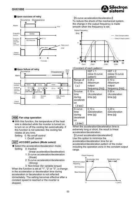
【S-curve acceleration/deceleration】<br />
To reduce the shock of the mechanical system,<br />
the change in the output frequency is made<br />
smooth when the frequency is set.<br />
Output frequency<br />
Protective<br />
function<br />
Active<br />
f[Hz]<br />
Slow S-shape pattern<br />
Protective<br />
function<br />
automatic<br />
reset<br />
command<br />
H05 Wait time<br />
0.1S s<br />
Retry count<br />
α<br />
Steep S-shape pattern<br />
Start<br />
clear<br />
Output<br />
frequency<br />
¡Upon failure of retry<br />
Occurrence<br />
Alarm<br />
Protective<br />
function<br />
Protective<br />
function<br />
automatic<br />
reset<br />
command<br />
Output<br />
frequency<br />
Occurrence<br />
Active<br />
Active<br />
Active<br />
0.1S s 0.1S<br />
s 0.1S<br />
s<br />
H05:<br />
H05:<br />
(Wait (wait time)<br />
(Wait (wait time)<br />
First<br />
time<br />
5 minutes<br />
Second<br />
time<br />
Disappearance<br />
H04: (Count)<br />
setting<br />
Active<br />
Alarm<br />
reset<br />
End of retry<br />
H06 Fan stop operation<br />
"!With this function, the temperature of the heat<br />
sink is detected while the inverter is turned on,<br />
to turn on or off the cooling fan automatically. If<br />
this function is not selected, the cooling fan<br />
rotates at any time.<br />
Setting 0: No on/off control<br />
1: On/off control<br />
H07 ACC/DEC pattern (Mode select)<br />
"!Select the acceleration/deceleration mode.<br />
Setting 0: Inactive<br />
(linear acceleration/deceleration)<br />
1: S-curve acceleration/deceleration<br />
(Weak)<br />
2: S-curve acceleration/deceleration<br />
(Strong)<br />
3: Non-linear (for variable torque)<br />
When the function is set at "1", "2" or "3", a change<br />
in the acceleration or deceleration time during<br />
acceleration or deceleration is not reflected<br />
immediately. The setting becomes effective after a<br />
constant speed is reached or the inverter is<br />
stopped.<br />
α α<br />
0<br />
βacc β βacc β βdec β β βdec<br />
<br />
H07 = 1<br />
(slow S-curve<br />
pattern)<br />
Range of<br />
S-curve<br />
(α)<br />
S-curve<br />
time<br />
during<br />
accelerati<br />
on<br />
(βacc)<br />
S curve<br />
time<br />
during<br />
decelerati<br />
on<br />
(βdec)<br />
0.05 x<br />
(Maximum<br />
output<br />
frequency [Hz])<br />
0.10 x<br />
(Acceleration<br />
time [s])<br />
0.10 x<br />
(Deceleration<br />
time [s])<br />
t[s]<br />
H07 = 2<br />
(steep S-curve<br />
pattern)<br />
0.10 x<br />
(Maximum<br />
output<br />
frequency [Hz])<br />
0.20 x<br />
(Acceleration<br />
time [s])<br />
0.20 x<br />
(Deceleration<br />
time [s])<br />
When the acceleration/deceleration time is<br />
extremely long or short, the result is linear<br />
acceleration/deceleration.<br />
【Curved acceleration/deceleration】<br />
Use this option to minimize the<br />
acceleration/deceleration time for an<br />
acceleration/deceleration pattern of the motor<br />
including the operation zone in the constant output<br />
range.<br />
Maximum output<br />
frequency<br />
Set frequency<br />
Base frequency<br />
Output frequency<br />
0<br />
Acceleration time<br />
Deceleration time<br />
t[sec]<br />
53
<strong>GVX1000</strong><br />
H09 Start mode (Rotating motor pickup)<br />
"!This function smoothly starts a motor coasting<br />
due to an external force or the like after<br />
momentary power failure.<br />
The speed of the motor is detected upon power<br />
recovery or restart and the same frequency as<br />
that for the motor speed is output. Therefore the<br />
motor starts smoothly without a shock.<br />
However, when the coasting speed of the motor<br />
converted in the inverter frequency exceeds 120<br />
Hz, setting of F03 "Maximum frequency 1" or<br />
setting of F15 "Frequency limiter (High)", the<br />
regular starting method is adopted.<br />
Restarting after<br />
Setting Regular starting momentary<br />
power failure<br />
0 Inactive Inactive<br />
1 Inactive Active<br />
2 Active Active<br />
"!Description of setting<br />
1:This function is effective when the setting of F14<br />
"Restart after momentary power failure<br />
(Operation selection)" is "2" or "3".<br />
Starting is made at the same frequency as that<br />
for the coasting speed.<br />
2:Upon restart after momentary power failure,<br />
operation command ON and other starting<br />
methods, the speed of the coasting motor is<br />
detected and starting is made at the same<br />
frequency as that for the coasting speed.<br />
Note) When this function is used, use the<br />
following setting to detect the accurate<br />
rotation speed of the motor.<br />
When a motor other than the one made by<br />
Bonfiglioli Riduttori is used or when the wiring<br />
length is long, perform P04 Tuning.<br />
H10 Energy-saving operation<br />
"!When the output frequency for a small load is<br />
constant (constant speed operation) and the<br />
setting of F09 "Torque boost 1" is other than "0",<br />
the output voltage is automatically lowered to<br />
minimize the product (power) of the voltage and<br />
the current.<br />
Setting 0: Inactive<br />
1: Active<br />
Notes)<br />
1. Use this function for fans, pumps or other<br />
square reduction torque loads. If this function is<br />
applied to a constant torque load or to an<br />
application with a rapidly changing load, there is<br />
a delay in the control response.<br />
2. The energy-saving operation is automatically<br />
cancelled to resume regular operation during<br />
acceleration or deceleration or when the torque<br />
limiter function is activated.<br />
H11 Dec mode<br />
"!Select the stopping method of the inverter after<br />
a stop command.<br />
Setting 0: Normal<br />
(Deceleration to stop based on data of<br />
H07 "ACC/DEC pattern")<br />
1: Coast-to-stop<br />
Note) This function is not activated when the<br />
set frequency is lowered to stop. The<br />
function is activated only when a stop<br />
command is input.<br />
H12 Instantaneous over current limiting<br />
"!When the motor load abruptly changes to cause<br />
a current exceeding the protective level of the<br />
inverter to flow, the inverter trips due to the over<br />
current. The Instantaneous over current limiting<br />
function controls the inverter output within the<br />
protective level even upon an excessive load.<br />
"!The operation level of the Instantaneous over<br />
current limiting cannot be adjusted. Use the<br />
torque limit function to set on output limitation.<br />
"!The torque generated by the motor may<br />
become low in a Instantaneous over current<br />
limiting state. Therefore deactivate the<br />
momentary over current limit function for<br />
applications such as the elevator where the<br />
torque generated by the motor must not be low.<br />
In this case, because the inverter trips due to an<br />
over current when a current exceeding the<br />
protective level of the inverter flows, use forcible<br />
stopping measures by a mechanical brake or<br />
other protective measures.<br />
Setting 0: Inactive<br />
1: Active<br />
H13 Auto-restart (Restart time)<br />
"!When the power supply to a running motor is<br />
shut off or power failure occurs and the power<br />
supply is quickly switched to another system,<br />
the phase of the voltage of the new system<br />
deviates from the phase of the voltage<br />
remaining in the motor and electrical or<br />
mechanical trouble may be developed. When<br />
switching the power supply system in a short<br />
time, write the time for attenuation of the<br />
remaining voltage from the motor after power<br />
shutoff. The setting is effective during restart<br />
after momentary power failure.<br />
Setting range: 0.1 to 5.0 s<br />
If the duration of momentary power failure is<br />
shorter than the wait time data, restart is made<br />
after this time. If the duration of momentary<br />
power failure is longer than the wait time data,<br />
restart is made after completion of operation<br />
preparation of the inverter (about 0.2 to 0.5 s).<br />
54
<strong>GVX1000</strong><br />
H14 Auto-restart (frequency fall rate)<br />
"!This function determines the drop ratio of the<br />
output frequency for the synchronization<br />
between the output frequency of the inverter<br />
and the motor speed, that is, the speed of<br />
synchronization. This function is also used to<br />
drop the frequency as a stall prevention function<br />
for an excessive load during regular operation.<br />
Setting range: 0.00, 0.01 to 100.0 Hz/s<br />
Set "0.00" to drop according to the currently<br />
selected deceleration time.<br />
Note) A large frequency drop ratio may cause<br />
temporary increase in the regeneration<br />
energy from the load, activating the over<br />
voltage protection function. On the<br />
contrary, a small frequency drop ratio<br />
may cause long operation time of the<br />
current limit function, activating the<br />
inverter overload protection function.<br />
H20 PID control (mode select)<br />
to<br />
H25 PID control (feedback filter)<br />
"!The PID control detects a control amount<br />
(feedback value) from the sensor of the<br />
controlled object and compares it with the<br />
reference value (set temperature, etc).. Upon<br />
difference between them, an action is taken to<br />
reduce the difference. That is, this control<br />
method makes the feedback value become<br />
consistent with the reference value. This<br />
method can be applied to flow control, pressure<br />
control, temperature control and other process<br />
controls.<br />
+ {<br />
+ { Driving<br />
Target of<br />
P ‚ o<br />
-<br />
part<br />
control<br />
Reference<br />
+ { + {<br />
‚ I h<br />
"!Because forward and reverse operation can be<br />
selected for the output of the PID controller, the<br />
rpm of the motor can be increased or decreased<br />
in relation to the output of the PID controller.<br />
H20<br />
Setting 0: Inactive<br />
1: Normal operation<br />
2: Inverse operation<br />
Maximum<br />
frequency<br />
Inverter output<br />
frequency<br />
0<br />
Normal operation<br />
Inverse operation<br />
0% PID output 100%<br />
"!The reference value can be given at F01<br />
"Frequency command 1" or directly input from<br />
the keypad panel.<br />
Select an arbitrary terminal from E01 "X1<br />
terminal (Function selection)" through E05 "X5<br />
(Function selection), and set data "9" (frequency<br />
command 2 / frequency command 1).<br />
To obtain the reference value from F01<br />
"Frequency command 1", input an OFF signal to<br />
the selected terminal. When inputting directly<br />
from the keypad panel, turn the selected<br />
terminal on.<br />
"!The process amount of the reference value and<br />
feedback value can be displayed based on the<br />
setting at E40 "Display coefficient A" and E41<br />
"Display coefficient B".<br />
Display coefficientA<br />
‚ D c<br />
Feedback value<br />
Display coefficient B<br />
0 100%<br />
100% reference value<br />
feedback value<br />
55
<strong>GVX1000</strong><br />
H21 PID control (Feedback signal)<br />
"!Select the feedback value input terminal and<br />
electrical specification of the terminal. Select<br />
one from the table below according to the<br />
specifications of the sensor.<br />
Setting Selection item<br />
Control terminal 12, normal operation<br />
0<br />
(voltage input 0 to +10V)<br />
Control terminal C1, normal<br />
1<br />
operation (current input 4 to 20 mA)<br />
Control terminal 12, inverse<br />
2<br />
operation (voltage input +10 to 0V)<br />
Control terminal C1, inverse<br />
3<br />
operation (current input 20 to 4 mA)<br />
Note)<br />
The feedback value of the PID control<br />
can be input only in the positive polarity.<br />
The negative polarity (0 to -10 Vdc, -10 to<br />
0 Vdc, etc). cannot be input. Therefore<br />
the control cannot be applied to<br />
reversible operation using the analogue<br />
signal.<br />
Feedback value<br />
100% “<br />
Normal operation<br />
Inverse operation<br />
0%<br />
“<br />
0V<br />
4mA<br />
Input<br />
10V<br />
20mA<br />
E01 to E05 (Function)<br />
Frequency setting 1/2 switch<br />
E01 to E05 (Function) PID<br />
control cancel<br />
Direct frequency setting<br />
at keypad panel<br />
Process amount setting<br />
at keypad panel<br />
Setting selected at F01<br />
Frequency setting 1<br />
#<br />
”9<br />
{<br />
|<br />
PID<br />
calculator<br />
Forward<br />
operation<br />
Reverse<br />
operation<br />
#<br />
”1<br />
#<br />
”2<br />
H20 (Operation<br />
selection)<br />
#16<br />
”16<br />
Frequency<br />
command<br />
#<br />
”0<br />
#<br />
”2<br />
#<br />
”1<br />
#<br />
”3<br />
Driving<br />
part<br />
Signal<br />
reverse<br />
Signal<br />
reverse<br />
Terminal 12<br />
Terminal C1<br />
Control<br />
target<br />
Note: Numbers marked # indicate the<br />
setting of each function.<br />
H21 (Setting signal switch)<br />
56
<strong>GVX1000</strong><br />
H22 PID control (P gain)<br />
"!Generally speaking, P: gain, I: integral time and<br />
D: differential time are not used alone.<br />
Functions are combined like: P control, PI<br />
control, PD control and PID control.<br />
"!P action<br />
An operation where there is proportional<br />
relationship between the amount of operation<br />
(output frequency) and deviation is called P<br />
operation. Therefore the P action outputs an<br />
operation amount proportional to the deviation.<br />
However, the deviation cannot be eliminated by<br />
only the P action.<br />
Setting range: 0.01 to 10.00 times<br />
With a long integral time, the response is slow<br />
and reaction to an external force is small. With a<br />
small integral time, the response is quick. When<br />
the integral time is too small, there is hunting.<br />
H24 PID control (D Differential time)<br />
"!D action<br />
An operation where the amount of operation is<br />
proportional to the differential value of the<br />
deviation is called D action. Therefore, the D<br />
action outputs an operation amount obtained<br />
from the differentiation of the deviation and the<br />
response to abrupt changes is quick.<br />
Deviation<br />
Amount<br />
of<br />
operation<br />
Time<br />
Deviation<br />
Amount<br />
of<br />
operation<br />
Time<br />
"!The P gain is a parameter which determines the<br />
degree of response to the deviation of P action.<br />
With a large gain, the response is quick but<br />
hunting is likely to occur. With a small gain, the<br />
response is stable but slow.<br />
Time<br />
H23 PID control (I integral time)<br />
"!I action<br />
An operation where the speed of the change in<br />
the amount of operation is proportional to the<br />
deviation is called I action. Therefore the I<br />
action outputs an operation amount obtained<br />
from integration of the deviation. For this<br />
reason, the I action is effective to converge the<br />
control amount to the reference value. However,<br />
response is slow to the deviation with abrupt<br />
changes.<br />
Response<br />
Deviation<br />
Amount<br />
of<br />
operation<br />
Setting range: 0.0 Inactive, 0.1 to 3600 s<br />
To determine the effect of the I action,<br />
I: integral time is used as a parameter.<br />
Time<br />
Setting range: 0.00 Inactive, 0.01 to 10.0 s<br />
D: differential time is used as a parameter to<br />
determine the effect of the D action. With a long<br />
differential time, decrease in the vibration<br />
caused by the P action upon deviation is quick.<br />
With too large a differential time, vibration may<br />
become larger. With a small differential time,<br />
decrease in the deviation becomes smaller.<br />
"!PI control<br />
Deviation remains with P action only. To<br />
eliminate the remaining deviation, I action is<br />
added and P + I control is generally adopted.<br />
The PI control functions to always eliminate<br />
deviation in spite of changes in the reference<br />
value and stationary disturbances. However,<br />
when the I action is strong, response to the<br />
deviation with abrupt changes is slow.<br />
P action only can be used for loads with an<br />
integral factor.<br />
"!PD control<br />
Upon deviation, the PD control generates an<br />
operation amount larger than that obtained by D<br />
action only, to reduce the increase of the<br />
deviation. When deviation is reduced to small,<br />
the function of the P action is made smaller.<br />
For a load including integral factors to be<br />
controlled, the P action alone can cause hunting<br />
in the response due to the action of the integral<br />
factors. The PD control is used in such cases to<br />
decrease hunting of the P action to stabilize.<br />
That is, this control method is applied to loads<br />
having no braking in the process itself.<br />
"!PID control<br />
The function of the I action to reduce the<br />
deviation and the function of the D action to<br />
suppress hunting are combined with the P<br />
action. Accurate responses without deviation<br />
are obtained.<br />
57
<strong>GVX1000</strong><br />
This control method is effective to loads which<br />
take time from generation of deviation to<br />
development of a response.<br />
H25 PID control (feedback filter)<br />
"!This function provides a filter for the feedback<br />
signal input at control terminal 12 or C1. The<br />
filter makes the operation of the PID control<br />
system stable. However, an excessively large<br />
setting causes a poor response.<br />
Setting range: 0.0 to 60.0 s<br />
H26 PTC thermistor (mode select)<br />
"!Select this function for a motor equipped with a<br />
PTC thermistor for overheat protection.<br />
Setting 0: Inactive<br />
1: Active<br />
Connect the PTC thermistor as shown in the<br />
figure. The protective operation is common with<br />
the external alarm input. Therefore the<br />
protective function operates at the "external<br />
alarm".<br />
Resistor<br />
1000Ω<br />
PTC thermistor<br />
11<br />
13<br />
C1<br />
DC10V<br />
Resistor250Ω<br />
OV<br />
‚g‚Q‚V H27<br />
(Operation level)<br />
Comparator<br />
External<br />
alarm<br />
H27 PTC thermistor (level)<br />
"!The voltage input at terminal [C1] is compared<br />
with the set voltage and, when the input voltage<br />
at terminal [C1] is larger than the set voltage<br />
(operation level), H26 "PTC thermistor<br />
(Operation selection)" is activated.<br />
Setting range: 0.00 to 5.00 V<br />
(The setting smaller than 0.10 is handled as<br />
0.10).<br />
"!The alarm temperature is determined by the<br />
PTC thermistor and the internal resistance of<br />
the PTC thermistor changes largely at the alarm<br />
temperature. Set the operation (voltage) level<br />
using this change of resistance.<br />
/PTC thermistor internal resistance<br />
Rp2<br />
Rp1<br />
Alarm temperature<br />
Temperature<br />
From the figure of H26 "PTC thermistor<br />
(Operation selection)", the 250-ohm resistor and<br />
the PTC thermistor (resistance Rp) configure a<br />
parallel circuit. Therefore voltage VC1 (operation<br />
level) of terminal [C1] is calculated in the<br />
following equation.<br />
250 ⋅ Rp<br />
250 + Rp<br />
Vc<br />
1<br />
=<br />
⋅10<br />
[V]<br />
250 ⋅ Rp<br />
1000 +<br />
250 + Rp<br />
The operation level can be set when Rp of the<br />
Vc1 calculation equation is in the following<br />
range.<br />
Rp1 < Rp < Rp2<br />
To determine RP simply, calculate the following<br />
equation.<br />
Rp 1<br />
+ Rp<br />
Rp = 2<br />
[Ω]<br />
2<br />
H28 Droop operation<br />
◆ To drive one machine with two or more motors,<br />
a larger load is exerted on the motor with a<br />
larger speed. The droop control attributes<br />
drooping characteristics to the speed during<br />
load fluctuation to balance the load.<br />
◆ The drooping amount is calculated in the<br />
following formula.<br />
Drooping amount = Base frequency<br />
X<br />
Drooping content of speed at rated torque<br />
Synchronized speed [ r /min]<br />
Setting range: - 9.9 Hz to 0.0 Hz<br />
Droop operation<br />
Rated torque<br />
Torque<br />
Motor characteristics<br />
‚ O Synchronized<br />
speed<br />
Droop operation inactive<br />
Speed<br />
[ r /min]<br />
[ Hz]<br />
H30 Serial link (function select)<br />
"!RS485 (standard accessory) can be connected<br />
as a link function (communication function).<br />
"!As a link function, the following items are<br />
possible.<br />
1) Monitoring (monitoring of various data,<br />
confirmation of function code data)<br />
2) Frequency setting<br />
3) Operation command (FWD, REV and other<br />
commands set for digital input)<br />
4) Function code data writing<br />
Setting range: 0 to 3<br />
58
<strong>GVX1000</strong><br />
The validity of communication can be switched by<br />
a digital input. Set the link functions available<br />
through communications.<br />
Setting Frequency<br />
setting<br />
Operation<br />
command<br />
0 Invalid Invalid<br />
1 Valid Invalid<br />
2 Invalid Valid<br />
3 Valid Valid<br />
The monitor function and function code data<br />
writing function are always valid. When the<br />
communication is disabled by means of a digital<br />
input, a state similar to setting "0" is obtained.<br />
H31 RS485 (address)<br />
to<br />
H39 RS485 (response interval)<br />
"!Set the various conditions of RS485<br />
communication. Set according to the<br />
specifications of the host unit. Refer to section<br />
9-4 for protocol and other specifications.<br />
H31<br />
"!Set the station address of RS485.<br />
Setting range: 1 to 31<br />
H32 RS485 (mode select on no response error)<br />
"!Set the communication error handling process<br />
and the error handling timer value.<br />
Setting range: 0 to 3<br />
Setting Communication error handling process<br />
0 Immediate Er 8 trip (coast to stop)<br />
Operation continues until the timer time<br />
1<br />
elapses, then Er 8 trip.<br />
Operation continues and retry is made<br />
until the timer time elapses, then Er 8<br />
2 trip upon a communication error or<br />
continuation of operation upon no<br />
communication error.<br />
3 Operation continues.<br />
H33 RS485 (timer)<br />
"!Set the error handling timer value.<br />
Setting range: 0.0 to 60. 0 s<br />
H34 RS485 (baud rate)<br />
"!Set the transmission speed.<br />
Setting<br />
Transmission speed<br />
0 19200 bit/s<br />
1 9600 bit/s<br />
2 4800 bit/s<br />
3 2400 bit/s<br />
4 1200 bit/s<br />
H35 RS485 (data length)<br />
"!Set the data length.<br />
Setting<br />
Data length<br />
0 8 bits<br />
1 7 bits<br />
H36 RS485 (parity check)<br />
"!Set the parity bit.<br />
Setting Parity bit<br />
0 None<br />
1 Even<br />
2 Odd<br />
H37 RS485 (stop bits)<br />
"!Set the stop bit.<br />
Setting Stop bit<br />
0 2bits<br />
1 1bit<br />
H38 RS485 (no response error detection time)<br />
"!In a system where there is always an access to<br />
the station at certain intervals, no access<br />
caused by broken wire or other errors is<br />
detected and the inverter trips in Er8.<br />
Setting range: 0 to 60 s<br />
0: No detection<br />
H39 RS485 (response interval)<br />
"!Set the time taken until a response is sent back<br />
to the host unit upon a request.<br />
Setting range: 0.00 to 1.00 s<br />
H40 Maximum temperature of heat sink<br />
"!The maximum value in each hour is displayed in<br />
degree C.<br />
H41 Maximum effective current<br />
"!The maximum value in each hour is displayed in<br />
A.<br />
H42 Main circuit capacitor life<br />
"!The capacity of the capacitor in the main circuit<br />
is displayed in %. For the measuring conditions,<br />
refer to section 8-2 (1) "Measurement of<br />
capacitance of capacitor in main circuit".<br />
H43 Cooling fan operation time<br />
"!Integral hours is displayed. The displayed time<br />
is 0 to 6500, indicating 0 to 65000 hours.<br />
(Though the displayed value is in ten hours, the<br />
inverter adds each hour. Operation shorter than<br />
one hour is not counted).<br />
H44 Inverter ROM version<br />
"!The version of the software of the inverter is<br />
displayed.<br />
H45 Keypad panel ROM version<br />
"!The version of the software of the keypad panel<br />
is displayed.<br />
H46 Option ROM version<br />
"!For inverters with optional equipment, the<br />
version of the optional software is displayed.<br />
59
<strong>GVX1000</strong><br />
A: Alternative motor parameters<br />
A01 Maximum frequency 2<br />
The maximum frequency output by the inverter for<br />
motor 2. This parameter functions in the same way<br />
as F03 "Maximum output frequency 1". For the<br />
description, refer to F03 "Maximum output<br />
frequency 1".<br />
A02 Base frequency 2<br />
The maximum output frequency in the constant<br />
torque zone of motor 2, that is, the output<br />
frequency at the rated output voltage. This<br />
parameter functions in the same way as F04<br />
"Base frequency 1". For the description, refer to<br />
F04 "Base frequency 1".<br />
A03 Rated voltage 2 (at base frequency 2)<br />
The rated output voltage supplied to motor 2. This<br />
parameter functions in the same way as F04<br />
"Rated voltage 1". For the description, refer to F05<br />
"Rated voltage 1".<br />
A04 Maximum voltage 2 (at maximum<br />
frequency 2)<br />
The maximum output voltage of the inverter for<br />
motor 2. This parameter functions in the same way<br />
as F06 "Maximum voltage 1". For the description,<br />
refer to F06 "Maximum voltage 1".<br />
A05 Torque boost 2<br />
The torque boost function of motor 2. This<br />
parameter functions in the same way as F09<br />
"Torque boost 1". For the description, refer to F09<br />
"Torque boost 1".<br />
A06 Electronic thermal overload relay for<br />
motor 2 (Select)<br />
A07 Electronic thermal overload relay for<br />
motor 2 (Level)<br />
A08 Electronic thermal overload relay for<br />
motor 2 (Thermal time constant)<br />
The electronic thermal overload relay functions of<br />
motor 2. These parameters function in the same<br />
way as F10 through F12 Electronic thermal<br />
overload relay for motor 1. For the description,<br />
refer to F10 through F12.<br />
A09 Torque vector control 2<br />
The torque vector function of motor 2. This<br />
parameter functions in the same way as F42<br />
"Torque vector control 1". For the description, refer<br />
to F42 "Torque vector control 1".<br />
A10 Number of motor 2 poles<br />
The number of poles of driven motor 2. This<br />
parameter functions in the same way as P01<br />
"Number of motor 1 poles". For the description,<br />
refer to P01 "Number of motor 1 poles)".<br />
A11 Motor 2 (Capacity)<br />
The capacity of motor 2. This parameter functions<br />
in the same way as P02 "Motor 1 (Capacity)".<br />
For the description, refer to P02 "Motor 1<br />
(Capacity)". However, the function of related motor<br />
data changes to A12 "Motor 2 (Rated current)",<br />
A15 "Motor 2 (No-load current)", A16 "Motor 2<br />
(%R1 setting)" and A17 "Motor 2 (%X setting)".<br />
A12 Motor 2 (Rated current)<br />
The rated current of motor 2. This parameter<br />
functions in the same way as P03 "Motor 1 (Rated<br />
current)". For the description, refer to P03 "Motor<br />
1(Rated current)".<br />
A13 Motor 2 (Tuning)<br />
Tuning of motor 2. This parameter functions in the<br />
same way as P04 "Motor 1 (Tuning)". For the<br />
description, refer to P04 "Motor 1 (Tuning)".<br />
A14 Motor 2 (Online turning)<br />
Online tuning of motor 2. This parameter functions<br />
in the same way as P05 "Motor 1 (Online tuning)".<br />
For the description, refer to P05 "Motor 1 (Online<br />
turning)".<br />
A15 Motor 2 (No-load current)<br />
The no-load current of motor 2. This parameter<br />
functions in the same way as P06 "Motor 1 (Noload<br />
current)". For the description, refer to P06<br />
"Motor 1 (No-load current)".<br />
A16 Motor 2 (%R1 setting)<br />
A17 Motor 2 (%X setting)<br />
%R1 and %X of motor 2. These parameters<br />
function in the same way as P07 "Motor 1 (%R1<br />
setting)" and P08 "Motor 1 (%X setting)". For the<br />
description, refer to P07 and P08.<br />
A18 Motor 2 (Slip compensation control 2)<br />
The slip compensation control of motor 2. This<br />
parameter functions in the same way as P09<br />
"Motor 1 (Slip compensation control 1)". For the<br />
description, refer to P09 "Motor 1 (Slip<br />
compensation control 1)".<br />
A19 Motor 2 (Slip compensation response<br />
time 2)<br />
Set the response time for slip compensation of<br />
motor 2. This parameter functions in the same way<br />
as P10 "Motor 1 (Slip compensation response<br />
time)". For the description, refer to P10 "Motor 1<br />
(Slip compensation response time)".<br />
o: Optional functions<br />
o00 Option selection<br />
0: Option inactive<br />
1: Option active<br />
Set 0 when option card is used.<br />
Refer to the instruction manual of option card<br />
for detail of optional functions.<br />
60
<strong>GVX1000</strong><br />
6. Protective Operation<br />
6-1 List of Protective Operations<br />
When an error occurs to the inverter, a protective function is activated to trip the inverter immediately,<br />
displaying the name of the alarm at the LED and allowing the motor to coast to stop.<br />
Table 6-1-1 List of alarm display and protective operations<br />
Name of alarm Display Description of operation<br />
Over current<br />
protection<br />
Over voltage<br />
protection<br />
Under voltage<br />
protection<br />
Input phase loss<br />
protection<br />
Heat sink<br />
overheat<br />
External alarm<br />
input<br />
Braking resistor<br />
overheat<br />
Motor 1 overload<br />
Motor 2 overload<br />
OC1<br />
OC2<br />
OC3<br />
OU1<br />
OU2<br />
OU3<br />
LU<br />
Lin<br />
OH1<br />
OH2<br />
dbH<br />
OL1<br />
OL2<br />
During<br />
The protective function is activated when an over current flowing in the<br />
acceleration motor or a short circuit or ground fault in the output circuit causes the<br />
During<br />
instantaneous inverter output current to exceed the over current<br />
deceleration detection level.<br />
During constant<br />
speed operation<br />
During<br />
The protective function is activated when the regenerative power from<br />
acceleration the motor increases to cause the DC link voltage of the main circuit to<br />
During<br />
exceed the over voltage detection level (Approx. 400 Vdc for 200V<br />
deceleration class, Approx. 800V for 400V class). When an excessive voltage is<br />
During constant added to the source voltage, the inverter trips due to the over voltage,<br />
speed operation but inverter protection against the over voltage is impossible.<br />
The protective function is activated when the source voltage drops to cause the DC link<br />
voltage in the main circuit to become lower than the under voltage detection level (Approx.<br />
200 Vdc for 200V class, Approx. 400V for 400V class). If F14 Restart after momentary power<br />
failure has been selected, no alarm display is given. If the voltage drops below the control<br />
power maintenance level, no alarm is displayed.<br />
When the inverter is operated while one of the three phases of the power supply connected<br />
to the main power supply input terminals L1/R, L2/S and L3/T of the main circuit is missing or<br />
there is an unbalance among the three-phase voltages, the rectifying diode or smoothing<br />
capacitor of the main circuit may be broken. The inverter is stopped upon an alarm in these<br />
cases.<br />
The protective function is activated when the temperature of the heat sink of the inverter is<br />
high because of a broken cooling fan or for other reasons.<br />
The protective function is activated by a contact signal from an alarm contact of the external<br />
device such as the braking unit, braking resistor, and external thermal overload relay<br />
connected to the control circuit terminal (THR). Or an overheat protective function is activated<br />
by the PTC thermistor.<br />
If the electronic thermal overload relay (for braking resistor) has been selected for function<br />
code F13, the protective function is activated upon a high operation frequency of the braking<br />
resistor to prevent the resistor from being burned due to the temperature rise.<br />
If electronic thermal overload relay 1 has been selected for function code F10, the protective<br />
function is activated by a motor current exceeding the set operation level.<br />
If motor 2 has been selected and driven and electronic thermal overload relay 2 has been<br />
selected for function code A06, the protective function is activated by the current in motor 2<br />
exceeding the set operation level.<br />
Inverter overload OLU<br />
The protective function is activated by an output current exceeding the overload current rating<br />
to protect the semiconductor elements in the main circuit of the inverter from high<br />
temperatures.<br />
Memory error Er1 The protective function is activated by a data writing error or other errors in the memory.<br />
Keypad panel<br />
communication<br />
error<br />
CPU error<br />
Option error<br />
Output phase<br />
loss<br />
RS485<br />
communication<br />
error<br />
Er2<br />
Er3<br />
Er4<br />
Er5<br />
Er7<br />
Er8<br />
The protective function is activated when a data transmission error or transmission stoppage<br />
is detected between the keypad panel and the control section in the keypad panel operation<br />
mode.<br />
The protective function is activated by electric noise or other errors developed in the CPU, or<br />
if P24 is overloaded.<br />
Error during operation of option<br />
The protective function is activated during auto tuning when there is a broken wire or no<br />
connection in the inverter output circuit.<br />
The protective function is activated when a communication error occurs during<br />
communication through RS485.<br />
61
<strong>GVX1000</strong><br />
6-2 Alarm Reset<br />
When the inverter trips, remove the cause then press the PRG/RESET key on the keypad panel or input<br />
a reset command from the RST control terminal to reset the tripping state. Because the reset command is<br />
activated by an edge, supply the command in an OFF - ON - OFF sequence as shown in Fig. 6-2-1.<br />
When resetting the tripping state, deactivate the operation command. If the operation command is left<br />
turned on, the inverter starts operation immediately after the error is reset.<br />
10 ms or longer<br />
Reset command OFF ON OFF<br />
Keypad panel display<br />
Alarm display<br />
Regular display<br />
(ready to operate)<br />
Alarm output OFF ON OFF<br />
Trip<br />
Figure 6-2-1<br />
WARNING<br />
If an alarm reset is made with the operation signal turned on, a sudden start will<br />
occur. Check that the operation signal is turned off in advance.<br />
Otherwise an accident could occur.<br />
62
<strong>GVX1000</strong><br />
7. Troubleshooting<br />
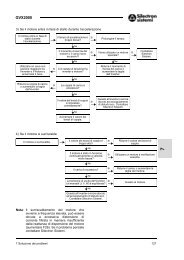
7-1 When Protective Function Goes Active<br />
(1) Over current<br />
Overcurrent during<br />
acceleration OC1<br />
Overcurrent during<br />
deceleration OC2<br />
Overcurrent during<br />
constant speed operation<br />
OC3<br />
NO<br />
Remove a short circuit or<br />
the part including a<br />
ground fault.<br />
Reduce the load or<br />
increase the inverter<br />
capacity.<br />
Check if the<br />
torque boost<br />
amount can be<br />
decreased.<br />
YES<br />
Decrease the torque<br />
boost amount.<br />
Failure of the inverter or<br />
malfunction caused by<br />
electric noise or other<br />
cause can be probable.<br />
Contact Contact Bonfiglioli Fuji Electric. Group<br />
YES<br />
YES<br />
NO<br />
NO<br />
Check if the motor connection terminal (U, V, W) circuit includes a<br />
short circuit or ground fault.<br />
NO NO NO<br />
Check if the torque<br />
boost amount is<br />
proper.<br />
Check if the<br />
acceleration time<br />
is too short for the<br />
load.<br />
Check if the load is too large.<br />
NO NO NO<br />
YES<br />
YES<br />
NO<br />
Check if the<br />
deceleration time is<br />
too short for the<br />
load.<br />
YES<br />
NO<br />
Check if there has<br />
been an abrupt<br />
change in the load.<br />
YES<br />
Set a longer time.<br />
YES<br />
Check if the<br />
acceleration time can<br />
be made longer.<br />
NO<br />
YES<br />
Check if the<br />
deceleration time<br />
can be made<br />
longer.<br />
NO<br />
Reduce the load<br />
fluctuation or<br />
increase the inverter<br />
capacity.<br />
Reduce the load or increase<br />
the inverter capacity.<br />
The braking method<br />
must be examined.<br />
Contact Fuji<br />
Bonfiglioli Electric. Group<br />
63
<strong>GVX1000</strong><br />
(2) Over voltage<br />
Overvoltage during<br />
acceleration OU1<br />
Overvoltage during<br />
deceleration OU2<br />
Overvoltage during<br />
constant speed<br />
operation OU3<br />
Decrease the source<br />
voltage to lower than the<br />
upper limit in the<br />
specifications.<br />
NO<br />
Check if the source voltage is within the range specified in<br />
the specifications.<br />
YES<br />
YES<br />
YES<br />
Check if operation is observed after sudden removal of the<br />
load.<br />
NO NO NO<br />
Failure of the inverter or<br />
malfunction due to<br />
electric noise or other<br />
cause is probable.<br />
Contact Bonfiglioli Fuji Electric. Group<br />
Reduce the inertia<br />
moment.<br />
NO<br />
NO<br />
Check if the DC link voltage of the main circuit during<br />
activation of the overvoltage is beyond the protective level.<br />
YES YES YES<br />
Check if operation<br />
is possible after<br />
sudden<br />
acceleration.<br />
YES<br />
Check if the acceleration<br />
time can be made longer.<br />
YES<br />
NO<br />
YES<br />
Check if the deceleration<br />
time can be made longer.<br />
NO<br />
NO<br />
Check if the inertia moment of the load can be made<br />
smaller.<br />
NO NO NO<br />
Check if a braking unit or DC control function is used.<br />
YES YES YES<br />
YES<br />
Set a longer<br />
deceleration<br />
time.<br />
Examination of the control method is necessary. Contact Bonfiglioli Fuji Electric. Group<br />
NO<br />
Examine<br />
applicati<br />
on of a<br />
braking<br />
unit or<br />
DC<br />
braking<br />
function.<br />
(3) Under voltage<br />
Undervoltage<br />
LU<br />
NO<br />
Check if power failure<br />
(including momentary one)<br />
has occurred.<br />
NO<br />
Check if there is failure of a<br />
device or poor contact in<br />
the power supply circuit.<br />
YES<br />
YES<br />
Reset and<br />
restart<br />
operation.<br />
Replace the<br />
defective device<br />
or repair the<br />
connection error.<br />
Failure of the inverter<br />
control circuit or<br />
malfunction due to<br />
electric noise or other<br />
cause is probable.<br />
Contact Bonfiglioli Fuji Electric. Group<br />
Check if the<br />
source voltage<br />
is within the<br />
range specified<br />
in the<br />
specifications.<br />
NO<br />
YES<br />
Check if there is a load<br />
requiring a large starting<br />
current in the same power<br />
supply system.<br />
YES<br />
Examine the power<br />
supply system so that<br />
the specification<br />
values are satisfied.<br />
NO<br />
Check if<br />
operation is<br />
observed when<br />
the circuit<br />
breaker and<br />
electromagnetic<br />
contactor are<br />
turned on.<br />
YES<br />
Check if the power supply<br />
transformer capacity is<br />
proper.<br />
NO<br />
YES<br />
YES<br />
Check if the current<br />
(across P and N)<br />
and the voltage of<br />
the main circuit are<br />
above the detection<br />
level specified in<br />
Table 6-1-1.<br />
NO<br />
Failure of the<br />
inverter is<br />
probable. Contact<br />
Bonfiglioli Fuji Electric. Group<br />
64
<strong>GVX1000</strong><br />
(4) Inverter inside overheat or heat sink overheat (5) Eternal alarm input<br />
Heat sink<br />
overheat OH1<br />
External alarm<br />
input OH2<br />
Confirm the heat<br />
sink temperature at<br />
the keypad panel.<br />
(H40)<br />
NO<br />
Check if the<br />
temperature of the<br />
heat sink is -10 KC<br />
or lower.<br />
NO<br />
YES<br />
he detection circuit<br />
in the printed circuit<br />
board is faulty.<br />
Contact Fuji<br />
Bonfiglioli Electric. Group<br />
NO<br />
Check if PTC<br />
input (H26) is set<br />
active.<br />
YES<br />
Check if the PTC is<br />
activated.<br />
NO<br />
YES<br />
A problem in the<br />
load or cooling<br />
system of the motor<br />
is probable. Check<br />
the motor.<br />
Check if the load<br />
exceeds the<br />
allowable limit.<br />
NO<br />
Check if the<br />
cooling fan<br />
rotates. YES<br />
NO<br />
Check if the path<br />
of cooling wind is<br />
blocked.<br />
NO<br />
Check if the<br />
ambient<br />
temperature is<br />
within the<br />
specification limits.<br />
NO<br />
Improve the ambient<br />
temperature to within<br />
the specification limits.<br />
YES<br />
YES<br />
YES<br />
YES<br />
(6) Inverter overload, motor overload<br />
Inverter overload<br />
OLU<br />
Reduce the load.<br />
Replace the cooling<br />
fan.<br />
Remove obstacles.<br />
Failure of the<br />
inverter or<br />
malfunction due to<br />
electric noise or<br />
other cause is<br />
probable. Contact<br />
Bonfiglioli Fuji Electric. Group<br />
Motor o verload<br />
OL1, OL2<br />
Check if the<br />
characteristics of the<br />
electronic thermal<br />
overload relay and the<br />
overload characteristics<br />
of the motor are in<br />
harmony.<br />
NO<br />
Connect an<br />
external thermal<br />
overload relay.<br />
Check if the<br />
operation level<br />
(H27) is set at the<br />
proper value. YES<br />
NO<br />
Check if the external<br />
circuit (including<br />
constants) is proper.<br />
YES<br />
Failure of the inverter or<br />
malfunction due to<br />
electric noise or other<br />
cause is probable.<br />
Contact Contact Bonfiglioli Fuji Electric. Group<br />
YES<br />
Check if control terminal<br />
function THR is<br />
assigned to X1 to X5<br />
and an alarm signal of<br />
the external device is<br />
connected between the<br />
terminal and the CM P24<br />
terminal.<br />
NO<br />
Connect the alarm<br />
signal contact.<br />
YES<br />
Failure of the inverter or<br />
malfunction due to<br />
electric noise or other<br />
cause is probable.<br />
Contact Bonfiglioli Fuji Electric. Group<br />
NO<br />
NO<br />
NO<br />
NO<br />
Change to a proper<br />
value.<br />
Change to the<br />
correct external<br />
circuit.<br />
Check if the alarm<br />
function of the<br />
connected external<br />
device is activated.<br />
Remove the cause<br />
of activation of the<br />
alarm function.<br />
YES<br />
Check if the electronic<br />
thermal overload relay<br />
is properly set.<br />
YES<br />
Check if the load is<br />
excessive.<br />
YES<br />
NO<br />
NO<br />
Set to the proper<br />
level.<br />
Failure of the inverter or malfunction<br />
due to electric noise or other cause is<br />
probable. Contact Bonfiglioli Fuji Electric. Group<br />
Reduce the load or increase<br />
the inverter capacity.<br />
65
<strong>GVX1000</strong><br />
(7) Memory error Er1, keypad panel<br />
communication error Er2, CPU error Er3<br />
(8) Output wiring error<br />
Er1/2/3 display,<br />
irregular display or<br />
dark display<br />
Turn the power<br />
off, wait until the<br />
charge lamp<br />
(CRG) is unlit,<br />
then turn the<br />
power on again.<br />
Check if the<br />
correct data is<br />
displayed on the<br />
LED.<br />
The inverter is<br />
correct. continue<br />
operation.<br />
NO<br />
Correct the point of<br />
trouble.<br />
NO<br />
Check if the<br />
connectors, sockets,<br />
ICs and other parts<br />
are properly<br />
connected and if<br />
there is no source of<br />
electric noise<br />
nearby.<br />
YES<br />
Failure of the<br />
inverter. Contact<br />
Bonfiglioli Fuji Electric. Group<br />
YES<br />
Output wiring<br />
error Er7<br />
Check if the error<br />
occurs during<br />
tuning.<br />
NO<br />
Check if the braking braking<br />
unit or damping<br />
resistor is<br />
erroneously<br />
connected.<br />
NO<br />
Failure of the inverter<br />
or malfunction due to<br />
electric noise or other<br />
cause is probable.<br />
Contact Bonfiglioli Fuji Electric. Group<br />
YES<br />
Connect correctly<br />
or correct the<br />
wiring.<br />
(9) Input phase lack loss<br />
Input<br />
Input<br />
phase<br />
phase<br />
loss<br />
lack<br />
Lin<br />
Lin<br />
Check if all the<br />
power supply<br />
terminals L1/R,<br />
L2/S and L3/T of<br />
the main circuit are<br />
connected with<br />
cables.<br />
NO<br />
Check if the screw<br />
of the terminal<br />
block is loose.<br />
NO<br />
Check if there is a<br />
Check large if voltage there is a<br />
imbalance among<br />
three phase supply<br />
phases.<br />
YES<br />
YES<br />
YES<br />
Connect all the<br />
three phases.<br />
Tighten the screw<br />
of the terminal<br />
block.<br />
The power supply<br />
is faulty. Inspect<br />
the power supply<br />
system including<br />
wiring.<br />
Check if the circuits<br />
at terminal U, V and<br />
W are disconnected<br />
or there is a broken<br />
wire in them.<br />
NO<br />
Check if the<br />
connector for<br />
connecting the<br />
keypad panel is<br />
disconnected.<br />
NO<br />
Check if control<br />
terminal FWD or<br />
REV is connected<br />
with the P24 CM<br />
terminal.<br />
NO<br />
Failure of the inverter<br />
or malfunction due to<br />
electric noise or other<br />
cause is probable.<br />
Contact Bonfiglioli Fuji Electric. Group<br />
YES<br />
YES<br />
YES<br />
Connect correctly<br />
or correct the<br />
wiring.<br />
Insert the<br />
connector.<br />
Disconnect the<br />
connection.<br />
Failure of the inverter<br />
or malfunction due to<br />
electric noise or other<br />
cause is probable.<br />
Contact Bonfiglioli Fuji Electric. Group<br />
66
<strong>GVX1000</strong><br />
7-2 When Motor rotates Incorrectly<br />
(1) The motor does not rotate.<br />
The motor does not<br />
rotate.<br />
Remove the cause of<br />
the alarm, reset the<br />
alarm then start<br />
operation.<br />
Continue operation if<br />
no error is found.<br />
YES<br />
Check if the motor<br />
rotates when the<br />
RUN key is pressed.<br />
NO<br />
YES<br />
Check if the charge<br />
lamp (CRG) is lit and<br />
that the keypad panel<br />
displays something.<br />
YES<br />
Check if the alarm<br />
mode screen is<br />
displayed.<br />
NO<br />
Check if the operation<br />
commands are input<br />
through the keypad<br />
panel or through the<br />
control terminals.<br />
NO<br />
Check if the circuit<br />
breaker and<br />
electromagnetic<br />
contactor of the power<br />
supply are turned on.<br />
YES<br />
Check if the voltage<br />
at the power supply<br />
terminal (R/L1, S/L2,<br />
T/L3) is correct.<br />
YES<br />
Check if a jumper or<br />
DC reactor is<br />
connected across<br />
terminals P1 and P (+).<br />
NO<br />
NO<br />
NO<br />
Turn them on.<br />
Check for voltage<br />
drop, phase lack,<br />
connection errors,<br />
poor contact and<br />
other problems and<br />
take necessary<br />
actions.<br />
Connect.<br />
Keypad<br />
Control<br />
YES<br />
Failure of the inverter<br />
panel<br />
terminal<br />
is is probable. Contact<br />
Bonfiglioli Fuji Electric. Group<br />
Check if the external<br />
Check if the forward<br />
circuit wiring across<br />
NO NO YES The switch or relay is<br />
or reverse operation<br />
control terminals FWD and<br />
faulty; replace the<br />
command is input.<br />
REV and the P24 CM terminal<br />
faulty parts.<br />
is connected correctly.<br />
YES<br />
YES<br />
NO<br />
Press the up or down<br />
key to set the<br />
frequency.<br />
YES<br />
Check if the motor<br />
rotates when the<br />
up or down key is<br />
pressed.<br />
NO<br />
Set the correct<br />
frequency.<br />
YES<br />
NO<br />
YES<br />
Check if the<br />
frequency is set.<br />
YES<br />
Check if the upper<br />
frequency limiter and<br />
the set frequency are<br />
smaller than the<br />
starting frequency.<br />
NO<br />
NO<br />
Check if control terminals<br />
13, 12, 11 and C1 or, with<br />
multistep frequency<br />
selection, external circuit<br />
wiring across X1 to X5 and<br />
the P24 CM terminal is<br />
connected correctly.<br />
YES<br />
NO<br />
Correct the wiring.<br />
The frequency setting<br />
unit, signal converter,<br />
switch, relay contact or<br />
other unit is faulty.<br />
Replace the faulty<br />
parts.<br />
Failure of motor.<br />
NO<br />
Check that the<br />
voltage is present at<br />
the inverter output<br />
terminals (U, V, W).<br />
YES<br />
NO<br />
Failure of the inverter<br />
is is probable. Contact<br />
Bonfiglioli Fuji Electric. Group<br />
Check if the load<br />
is excessive.<br />
YES<br />
Check if the torque<br />
boost amount is<br />
correctly set.<br />
NO<br />
YES<br />
YES<br />
Check if the wiring to<br />
the motor is correct.<br />
NO<br />
The load is excessively large and the motor is<br />
locked. Reduce the load. For motors with a<br />
mechanical brake, check that the brake is<br />
released.<br />
Correct the wiring.<br />
Note: For the<br />
operation command<br />
frequency setting<br />
and other data,<br />
select each function<br />
and monitor at the<br />
keypad panel.<br />
Increase the torque<br />
boost amount.<br />
The motor does not start when a coast-to-stop command or DC braking command is being input.<br />
67
<strong>GVX1000</strong><br />
(2) The motor rotates but the speed does not change.<br />
The motor rotates<br />
but the speed does<br />
not change.<br />
Check if the<br />
maximum frequency<br />
setting is small.<br />
NO<br />
YES<br />
Set a larger value.<br />
Change the<br />
setting.<br />
YES<br />
Check if the upper/<br />
lower frequency<br />
limiter is activated.<br />
Set the frequency.<br />
YES<br />
YES<br />
YES<br />
Check if the timer<br />
time is too long.<br />
NO<br />
Check if the end<br />
of the pattern is<br />
reached.<br />
NO<br />
Check if the<br />
acceleration time<br />
and deceleration<br />
time are identical.<br />
NO<br />
Pattern<br />
operation<br />
NO<br />
Check if the frequency<br />
setting method is<br />
keypad panel<br />
operation, analog<br />
signal, multistep<br />
frequency, or UP/<br />
DOWN method. Check<br />
if the operation method<br />
is pattern operation.<br />
Check if the wiring or<br />
the external circuits<br />
across control<br />
terminals X1 through<br />
X5 and the CM P24<br />
terminal are correct.<br />
YES<br />
Multistep frequency<br />
or UP/DOWN<br />
NO<br />
Keypad panel<br />
operation<br />
Analog signal<br />
Correct the wiring.<br />
YES<br />
Check if the speed<br />
changes when the up<br />
or down key is<br />
pressed.<br />
Check if the<br />
frequency setting<br />
signal (0 to +/-10 V, 4<br />
to 20 mA) changes.<br />
NO<br />
Check if the wiring of<br />
the external circuits<br />
with control<br />
terminals 13, 12, 11<br />
and C1 are correct.<br />
YES<br />
NO<br />
YES<br />
Check if the frequency<br />
of each step for<br />
multistep frequency is<br />
different from each<br />
other.<br />
NO<br />
Correct the<br />
frequency setting.<br />
Replace the frequency<br />
setting unit and signal<br />
converter because<br />
they are faulty.<br />
YES<br />
Failure of the inverter<br />
or malfunction due to<br />
electric noise or other<br />
cause is probable.<br />
Contact Bonfiglioli Fuji Electric. Group<br />
NO<br />
Check if the<br />
acceleration time and<br />
deceleration time are<br />
excessively long.<br />
YES<br />
Change to the time<br />
suitable for the<br />
load.<br />
The change in the rotation speed of the motor is also small in the following cases.<br />
— ”F01 "Frequency command 1" and C30 "Frequency command 2" are set at "3" and a signal is input from both<br />
of control terminals 12 and C1, and there is no change in the sum of them.<br />
— The load is excessively large and the torque limit and current limit functions are activated.<br />
68
<strong>GVX1000</strong><br />
(3) The motor loses speed during acceleration.<br />
The motor loses<br />
the speed during<br />
acceleration.<br />
Check if the<br />
acceleration time is<br />
too short.<br />
NO<br />
YES<br />
Increase the time.<br />
Use thicker cables<br />
for the wiring<br />
between the<br />
inverter the motor<br />
or reduce the wiring<br />
length.<br />
YES<br />
Check if the inertia<br />
moment of the motor<br />
or load is too large.<br />
NO<br />
Check if there is<br />
voltage drop at the<br />
terminal of the motor.<br />
NO<br />
YES<br />
Check if a special<br />
motor is used.<br />
NO<br />
Reduce the inertia<br />
moment of the load<br />
or increase the<br />
inverter capacity.<br />
YES<br />
Contact Contact Bonfiglioli Fuji Group<br />
Electric.<br />
Reduce the torque<br />
of the load or<br />
increase the<br />
inverter capacity.<br />
YES<br />
Check if the torque of<br />
the load is too large.<br />
NO<br />
Check if the torque<br />
boost amount is<br />
proper.<br />
NO<br />
YES<br />
Failure of the inverter,<br />
malfunction due to electric<br />
noise or other cause is<br />
is probable. Contact Fuji<br />
Bonfiglioli Electric. Group<br />
Increase the torque<br />
boost amount.<br />
(4) Excessive heat generation from motor<br />
69
<strong>GVX1000</strong><br />
Excessive heat<br />
generation from<br />
motor<br />
Check if the torque<br />
boost amount is too<br />
large.<br />
NO<br />
YES<br />
Reduce the torque boost<br />
amount.<br />
Check if continuous<br />
operation is made at<br />
extremely low speed.<br />
YES<br />
Use a special motor<br />
designed for the<br />
inverter.<br />
NO<br />
Check if the load is<br />
too large.<br />
YES<br />
Reduce the load or<br />
increase the motor<br />
capacity.<br />
NO<br />
Check if the output<br />
voltages (at U, V and<br />
W terminals) of the<br />
inverter are balanced.<br />
YES<br />
Failure of motor<br />
NO<br />
Failure of the inverter,<br />
malfunction due to electric noise<br />
or other cause is probable.<br />
Contact Contact Bonfiglioli Fuji Electric. Group<br />
Note: Heat generation with a large<br />
frequency setting may be caused by<br />
the waveform of the current. Contact<br />
Contact Fuji Electric. Bonfiglioli Group<br />
70
<strong>GVX1000</strong><br />
8. Maintenance and Inspection<br />
Perform daily and periodic inspection to avoid trouble and keep reliable operation for a long time. Take<br />
care of the following items during work.<br />
8-1 Daily Inspection<br />
Visually inspect errors in the state of operation from the outside without removing covers while the inverter<br />
operates or while it is turned on.<br />
1) Check if the expected performance (satisfying the standard specification) is obtained.<br />
2) Check if the surrounding environment satisfies the standard specification.<br />
3) Check that the display of the keypad panel is free from errors.<br />
4) Check for abnormal noise, excessive vibration and bad smell.<br />
5) Check for traces of overheat, discoloration and other defects.<br />
8-2 Periodic Inspection<br />
After stopping the operation, turn the power off and remove the front cover to perform periodic inspection.<br />
The smoothing capacitor at the DC section of the main circuit takes time to be discharged after the power<br />
is turned off. After checking that the charge lamp (CRG) is unlit, check that the DC voltage is lower than<br />
the safety level (25 VDC) using a multimeter or the like before starting work.<br />
WARNING<br />
• Turn the power off and wait for at least five minutes before starting inspection.<br />
(Further, check that the charge lamp is unlit and measure the DC voltage across the<br />
P (+) and N (-) terminals to check that it is lower than 25V).<br />
Otherwise electric shock could occur.<br />
• Maintenance and inspection and parts replacement should be made only by<br />
appointed persons.<br />
(Take off the watch, rings and other metallic matter before starting work).<br />
(Use insulated tools).<br />
• Never remodel.<br />
Otherwise electric shock or injuries could occur.<br />
Table 8-2-1 List of periodic inspection<br />
Check part Check item How to inspect Evaluation criteria<br />
1) Check the ambient temperature,<br />
humidity, vibration and atmosphere<br />
1) Check visually<br />
or measure<br />
1) The standard<br />
specification<br />
Environment<br />
(dust, gas, oil mist, water drops). using<br />
must be satisfied.<br />
2) Check if tools or other foreign matter apparatus. 2) No foreign or<br />
or dangerous objects are left around<br />
the equipment.<br />
2) Visual<br />
inspection<br />
dangerous<br />
objects are left.<br />
Voltage<br />
Keypad panel<br />
Structure such as<br />
frame and cover<br />
Check if the voltages of the main circuit<br />
and control circuit are correct.<br />
1) Check if the display is clear.<br />
2) Check if there is missing parts in the<br />
characters.<br />
1) Abnormal noise and excessive<br />
vibration<br />
2) Loose bolts (tightened parts)<br />
3) Deformation and breakage<br />
4) Discoloration and deformation<br />
caused by overheat<br />
5) Stains and dust<br />
Measure using a<br />
multimeter or the<br />
like.<br />
1), 2) Visual<br />
inspection<br />
1) Visual or<br />
hearing<br />
inspection<br />
2) Retighten.<br />
3), 4), 5) Visual<br />
inspection<br />
The standard<br />
specification must<br />
be satisfied.<br />
1, 2) The display<br />
can be read<br />
and there is<br />
no fault.<br />
1),2),3),4),5)<br />
No abnormalities<br />
71
<strong>GVX1000</strong><br />
Main circuit<br />
Main circuit<br />
Control circuit<br />
Cooling system<br />
Common<br />
Conductor<br />
and wire<br />
Terminal<br />
block<br />
Smoothing<br />
capacitor<br />
Resistor<br />
Transformer<br />
Relay<br />
Control<br />
printed circuit<br />
board,<br />
connector<br />
Cooling fan<br />
1) Check if bolts and screws are tight and<br />
not missing.<br />
2) Check the devices and insulators for<br />
deformation, cracks, breakage and<br />
discoloration caused by overheat and<br />
deterioration.<br />
3) Check for foulness and dust.<br />
1) Check the conductor for discoloration<br />
and distortion caused by overheat.<br />
2) Check the sheath of the cable for<br />
cracks and discoloration.<br />
1) Retighten.<br />
2), 3) Visual<br />
inspection<br />
1), 2) Visual<br />
inspection<br />
1), 2), 3) No<br />
abnormalities<br />
1), 2) No<br />
abnormalitie<br />
s<br />
Damage Visual inspection No abnormalities<br />
1) Check for electrolyte leakage,<br />
discoloration, cracks and swelling of<br />
the case.<br />
2) Check for safety valve protrusion and<br />
remarkably protruding valve<br />
3) Measure the capacitance.<br />
1) Check for odour caused by overheat<br />
and cracked insulator.<br />
2) Check for broken wire.<br />
Check for abnormal roaring noise and<br />
odour.<br />
1) Check for chatters during operation.<br />
2) Check for rough contacts.<br />
1) Check for loose screws and<br />
connectors.<br />
2) Check for odour and discoloration.<br />
3) Check for cracks, breakage,<br />
deformation and remarkable rust.<br />
4) Check the capacitors for electrolyte<br />
leaks and deformation.<br />
1) Check for abnormal noise and<br />
excessive vibration.<br />
2) Check for loose bolts.<br />
3) Check for discoloration caused by<br />
overheat.<br />
1), 2) Visual<br />
inspection<br />
3) Monitor H42 Life<br />
judgment and<br />
measure with<br />
capacitance<br />
probe.<br />
1) Smelling and<br />
visual inspection<br />
2) Visual inspection<br />
or measurement<br />
with multimeter<br />
under<br />
disconnection of<br />
one lead<br />
Hearing, visual and<br />
smelling inspection<br />
1) Hearing<br />
inspection<br />
2) Visual inspection<br />
1) Retighten.<br />
2) Smelling and<br />
visual inspection<br />
3), 4) Visual<br />
inspection<br />
1) Hearing and<br />
visual inspection,<br />
or turn manually<br />
(be sure to turn<br />
the power off).<br />
2) Retighten.<br />
3) Visual inspection<br />
4) Life judgment<br />
based on<br />
maintenance<br />
data*<br />
Visual inspection<br />
1), 2) No<br />
abnormalities<br />
3) Capacitance ≧<br />
(Initial value) x<br />
0.85<br />
1) No<br />
abnormalities<br />
2) Within ± 10% of<br />
displayed<br />
resistance<br />
No abnormalities<br />
1),2)<br />
No abnormalities<br />
1),2),3),4)<br />
No abnormalities<br />
1) Smooth rotation<br />
2),3)<br />
No abnormalities<br />
Ventilation<br />
path<br />
Check the heat sink, intake and exhaust<br />
ports for clogging and foreign matter.<br />
No abnormalities<br />
Remarks: Remove foulness using cleaning cloth which is chemically neutral. Use a vacuum cleaner to<br />
remove dust.<br />
72
<strong>GVX1000</strong><br />
*Judgment of life using maintenance data<br />
The maintenance data of function codes H42 and H43 can be used to display data for the judgment of the<br />
capacitance of the capacitor in the main circuit and the life of the cooling fan to obtain a measure for the<br />
judgment of parts replacement. The capacitor life forecast signal is issued at the Y1 and Y2 terminals<br />
according to the measured capacitance after the capacitance of the capacity reaches 85%.<br />
(1) Measurement of capacitance of capacitor in main circuit<br />
This inverter is provided with a function where the capacitance of the main circuit capacitor is<br />
automatically measured upon shutoff of the inverter under certain conditions and it is displayed on the<br />
keypad panel upon power-up.<br />
The capacitance of the capacitor is displayed in the reduction ratio (% display) of the initial value<br />
stored inside the inverter before shipment.<br />
Procedure of measurement of capacitor capacitance<br />
1. Remove the optional card from the inverter if it is mounted. Disconnect the braking unit or direct<br />
current bus to another inverter from the P (+) and N (-) terminals of the main circuit if there is any.<br />
The power factor improving reactor (DC reactor) may not be disconnected.<br />
2. Turn the digital inputs (FWD, REV, X1-X5) at the control terminals off. Disconnect the RS 485<br />
communication terminal if it is connected.<br />
3. Turn the main power supply on. Check that the cooling fan rotates. Check that the inverter is<br />
stopped. (The "OH2 external alarm" caused by deactivated digital input terminals does not cause a<br />
problem).<br />
4. Turn the main power supply off.<br />
5. After the charge lamp is unlit completely, turn the main power supply on again.<br />
6. Monitor function code H42 to check the capacitor capacitance (%).<br />
(2) Life of cooling fan<br />
Function code H43 indicates the total operation time of the cooling fan. The time is integrated in units of<br />
an hour and fractions shorter than an hour are ignored.<br />
The actual life of the fan is largely effected by the temperature. Take the time as a measure.<br />
Table 8-2-2 Measure for judgment of life based on maintenance data<br />
Part<br />
Judgment level<br />
Main circuit capacitor<br />
85% or lower of the initial value<br />
30,000 hours (4.0 kW or less), 25,000 hours (5.5 kW<br />
Cooling fan<br />
or more) *1<br />
*1: Assumed life of cooling fan at ambient inverter temperature of 40 degree C.<br />
73
<strong>GVX1000</strong><br />
8-3 Measurement of Electrical Amounts in Main Circuit<br />
Because the voltage and current of the power supply (input) of the main circuit of the inverter and the<br />
output (motor) include harmonic components, the indicated value varies according to the type of the<br />
meter. Use meters indicated in Table 8-3-1 when measuring with meters for commercial frequencies.<br />
Marketed power factor meters measuring phase difference between the voltage and current cannot<br />
measure the power factor. To obtain the power factor, measure the power, voltage and current on each<br />
of the input and output sides and calculate in the following formula.<br />
In case of Three-phase<br />
In case of Single-phase<br />
Electric power[W]<br />
Electric power[W]<br />
Power factor = × 100[%] Power factor =<br />
× 100[% ]<br />
3 × Voltage[V] × Current[A]<br />
Voltage[V] × Current[A]<br />
Table 8-3-1 Meters for measurement of main circuit<br />
Input (power supply) side Output (motor) side Link voltage<br />
(P(+)-N(-))<br />
Voltage Current Voltage Current<br />
Item<br />
Name of<br />
meter<br />
Ammeter<br />
A R , S , T<br />
Voltmeter<br />
V R , S , T<br />
Wattmeter<br />
W R , S , T<br />
Ammeter<br />
A U , V , W<br />
Voltmeter<br />
V U , V , W<br />
Wattmeter<br />
W U , V , W<br />
DC voltmeter<br />
V<br />
Type of<br />
meter<br />
Moving iron<br />
type<br />
Rectifier or<br />
moving iron<br />
type<br />
Digital<br />
power<br />
meter<br />
Moving iron<br />
type<br />
Rectifier<br />
type<br />
Digital<br />
power meter<br />
Moving coil<br />
type<br />
Symbol of<br />
meter<br />
Note) When the output voltage is measured by a rectifier type, an error may be included. To increase the<br />
accuracy, use a digital AC power meter.<br />
(L1/L)<br />
(L2/N)<br />
Fig. 8-3-1<br />
Connection of meters<br />
74
<strong>GVX1000</strong><br />
8-4 Insulation Test<br />
Because an insulation test is made in the factory before shipment, avoid a Megger test. If a Megger test is<br />
unavoidable, follow the procedure below. Because a wrong test procedure will cause breakage of the<br />
inverter, take sufficient care.<br />
A withstand voltage test will cause breakage of the inverter similarly to the Megger test if the test<br />
procedure is wrong. When the withstand voltage test is necessary, contact Bonfiglioli Group.<br />
(1) Megger test of main circuit<br />
1) Use a 500 VDC Megger and shut off the main power supply without fail during measurement.<br />
2) If the test voltage leaks to the control circuit due to the wiring, disconnect all the control wiring.<br />
3) Connect the main circuit terminals with a common cable as shown in Fig. 8-4-1.<br />
4) The Megger test must be limited to across the common line of the main circuit and the ground terminal<br />
( G).<br />
5) M Ω or a larger value displayed at the Megger indicates a correct state. (The value is for a discrete<br />
inverter).<br />
(2) Do not perform a Megger test or withstand voltage test to the insulation test control circuit of the control<br />
circuit. Prepare a high resistance range tester for the control circuit.<br />
1) Disconnect all the external wiring from the control circuit terminals.<br />
2) Perform a continuity test to the ground. 1 M Ω or a larger measurement indicates a correct state.<br />
(3) External main circuit and sequence control circuit<br />
Disconnect all the inverter terminals so that the test voltage is not applied<br />
8-5 Replacement Parts<br />
The life of the part is determined by the type of the part. The life of the part varies according to the<br />
environment and operating conditions, and replacement according to Table 8-5-1 is recommended.<br />
8-6 Inquiries about Product and Guarantee<br />
Table 8-5-1 Replacement parts<br />
(1) When making an inquiry<br />
Upon breakage of the product, uncertainties,<br />
failure or inquiries, report the following<br />
information to Bonfiglioli Group.<br />
a) Inverter type<br />
b) SER NO. (serial number of equipment)<br />
c) Date of purchase<br />
d) Inquiries (for example, point and extent of<br />
breakage, uncertainties, failure phenomena,<br />
and other circumstances)<br />
Fig. 8-4-1<br />
Megger test<br />
Name of part<br />
Cooling fan<br />
Smoothing<br />
capacitor<br />
Electrolytic<br />
capacitors on<br />
printed circuit<br />
board<br />
Standard<br />
replacement<br />
years<br />
3 years<br />
5 years<br />
7 years<br />
Replacement<br />
method and others<br />
Replace with a new<br />
part.<br />
Replace with a new<br />
part. (Replace after<br />
inspection).<br />
Replace with new<br />
circuit board.<br />
(Replace after<br />
inspection).<br />
Other parts<br />
Determine after<br />
-<br />
inspection.<br />
(2) Guarantee of the product<br />
The product guarantee term is one year after the date of delivering. However, the product will not be<br />
repaired free of charge in the following cases, even if the guarantee term has not expired:<br />
a) The cause includes incorrect usage or inappropriate repairs or remodelling.<br />
b) The product is used outside the standard specified range.<br />
c) The failure is caused by dropping, damage or breakage during transportation after the purchase.<br />
d) The cause is earthquake, fire, storm or flood, lightening, excessive voltage, or other types or secondary<br />
disasters.<br />
75
<strong>GVX1000</strong><br />
9. Specifications<br />
9-1 Standard Specifications<br />
(1) Single-phase 200V input<br />
Item<br />
Inverter type<br />
<strong>GVX1000</strong>-[][]-S<br />
Nominal applied motor *1<br />
Output ratings<br />
Input ratings<br />
Braking<br />
[kW]<br />
Detail specifications<br />
0.1 0.2 0.4 0.75 1.5 2.2<br />
0.1 0.2 0.4 0.75 1.5 2.2<br />
Rated capacity *2 [kVA] 0.31 0.59 1.1 1.9 3.1 4.3<br />
Rated voltage *3 [V] Three-phase 200V / 50 Hz, 200V, 220V, 230V / 60 Hz (with AVR function)<br />
Rated current *4<br />
Overload capability<br />
[A]<br />
Rated frequency [Hz]<br />
Phases, Voltage<br />
Frequency<br />
Voltage/frequency<br />
fluctuation<br />
Momentary voltage dip<br />
capability *5<br />
Rated current [A]<br />
(With DCR)<br />
0.8<br />
(0.7)<br />
1.5<br />
(1.4)<br />
3.0<br />
(2.5)<br />
150% of rated output current for 1 min.<br />
200% of rated output current for 0.5 s<br />
50, 60Hz<br />
Single-phase 200 to 240 V / 50 to 60 Hz *10<br />
5.0<br />
(4.0)<br />
8.0<br />
(7.0)<br />
11<br />
(10)<br />
Voltage : +10 to -10%<br />
Frequency : +5 to -5%<br />
Operation continues at 165V or higher voltage. When the input voltage<br />
drops below 165V from the rated voltage, operation continues for 15 ms.<br />
1.2 2.0 3.5 6.5 11.8 17.7<br />
(Without DCR) *9 2.3 3.9 6.4 11.4 19.8 28.5<br />
Required power supply<br />
capacity *6 [kVA]<br />
0.3 0.4 0.7 1.3 2.4 3.6<br />
Braking torque *7 [%] 100 70 40<br />
Braking torque *8 [%] 150<br />
DC braking<br />
Enclosure (IEC60529)<br />
Starting frequency: 0.0 to 60 Hz, braking current (0 to 100% in 1%<br />
increment), braking time (0.0 to 30.0 s)<br />
IP20<br />
Cooling method Natural cooling Fan cooling<br />
Mass [kg] 0.6 0.7 1.2 1.8 1.9<br />
*1 The applicable standard motor indicates the case for a 4P standard motor made by Bonfiglioli Group.<br />
*2 The rated capacity indicates the case for 230V output voltage.<br />
*3 Voltages larger than the source voltage cannot be output.<br />
*4 Amperage values in parentheses () are applicable to operation with 4 kHz or higher carrier<br />
frequencies (F26 = 4 or more) or ambient temperatures exceeding 40 °C.<br />
*5 Tests at standard load condition (85% load)<br />
*6 Indicates the value when using a DC reactor (DCR).<br />
*7 Indicates the average braking torque for decelerating and stopping a discrete motor from 60 Hz.<br />
(Varies according to the efficiency of the motor).<br />
*8 Indicates the value with an external braking resistor (option).<br />
*9 Calculated on assumption that the inverter is connected to 500kVA power supply.<br />
*10 Safe separation for control interface of this inverter is provided when this inverter is installed in over<br />
voltage category II. Basic insulation for control interface of this inverter is provided when this inverter<br />
is installed in over voltage category III.<br />
76
<strong>GVX1000</strong><br />
(2) Three-phase 400V input<br />
Item<br />
Inverter type<br />
<strong>GVX1000</strong>-[][]-T<br />
Nominal applied motor *1<br />
Output ratings<br />
Input ratings<br />
Braking<br />
[kW]<br />
Detail specifications<br />
0.4 0.75 1.5 2.2 4.0 5.5 7.5<br />
0.4 0.75 1.5 2.2 4.0 5.5 7.5<br />
Rated capacity *2 [kVA] 1.0 1.7 2.6 3.9 6.4 9.3 12<br />
Rated Voltage *3<br />
[V]<br />
Rated current *4 [A] 1.5<br />
(1.4)<br />
Overload capability<br />
Rated frequency [Hz]<br />
Phases, Voltage<br />
Frequency<br />
Voltage/frequency<br />
fluctuation<br />
Momentary voltage dip<br />
capability *5<br />
Rated current [A]<br />
(With DCR)<br />
Three-phase 380,400,415V/50Hz, 380,400,440,460V/60Hz<br />
(with AVR function)<br />
2.5 3.7 5.5 9.0 13<br />
(2.1) (3.7) (5.3) (8.7) (12)<br />
150% of rated output current for 1 min.<br />
200% of rated output current for 0.5s<br />
50, 60Hz<br />
Three-phase 380 to 480 V / 50 to 60Hz *11<br />
Voltage : +10 to -15% Voltage unbalance 2% or less *10<br />
Frequency : +5 to -5%<br />
Operation continues at 300V or higher voltage. When the input voltage<br />
drops below 300V from the rated voltage, operation continues for 15 ms.<br />
18<br />
(16)<br />
0.82 1.5 2.9 4.2 7.1 10.0 13.5<br />
(Without DCR) *9 1.8 3.5 6.2 9.2 14.9 21.5 27.9<br />
Required power supply<br />
capacity *6 [kVA]<br />
0.6 1.1 2.1 3.0 5.0 7.0 9.4<br />
Braking torque *7 [%] 70 40 20<br />
Braking torque *8 [%] 150<br />
DC braking<br />
Enclosure(IEC60529)<br />
Starting frequency: 0.0 to 60.0 Hz, braking current (0 to 100% in 1%<br />
increment), braking time (0.0 to 30.0 s)<br />
IP20<br />
Cooling method Natural cooling Fan cooling<br />
Mass [kg] 1.1 1.2 1.3 1.4 1.9 4.5<br />
*1 The applicable standard motor indicates the case for a 4P standard motor made by Bonfiglioli Group.<br />
*2 The rated capacity indicates the case for 415V output voltage.<br />
*3 Voltages larger than the source voltage cannot be output.<br />
*4 Amperage values in parentheses () are applicable to operation with 4 kHz or higher carrier<br />
frequencies (F26 = 4 or more) or ambient temperatures exceeding 40 °C.<br />
*5 Tests at standard load condition (85% load)<br />
*6 Indicates the value when using a DC reactor (DCR).<br />
*7 Indicates the average braking torque for decelerating and stopping a discrete motor from 60 Hz.<br />
(Varies according to the efficiency of the motor).<br />
*8 Indicates the value with an external braking resistor (option).<br />
*9 Calculated on assumption that the inverter is connected to 500kVA power supply.<br />
*10 Refer to IEC61800-3 5.2.3.<br />
*11 Safe separation for control interface of this inverter is provided when this inverter is installed in over<br />
voltage category II. Basic insulation for control interface of this inverter is provided when this inverter<br />
is installed in over voltage category III.<br />
77
<strong>GVX1000</strong><br />
9-2 Common Specifications<br />
Output frequency<br />
Control<br />
Item Detail specifications<br />
Maximum<br />
frequency<br />
50 to 400 Hz variable<br />
Base<br />
frequency<br />
25 to 400 Hz variable<br />
Starting<br />
frequency<br />
0.1 to 60.0 Hz variable, Holding time : 0.0 to 10.0s.<br />
Carrier 0.75 to 15 kHz (The carrier frequency may automatically drop to 0.75 kHz to<br />
frequency protect the inverter. )<br />
Accuracy Analogue setting: Within ± 0.2 % (25 ± 10 °C)<br />
Digital setting: Within 0.01% (-10 to +50 °C)<br />
Setting<br />
Analogue setting: 1/3000 of maximum output frequency<br />
resolution Keypad panel setting: 0.01 Hz (99.99 Hz or lower), 0.1 Hz (100.0 to 400.0 Hz)<br />
Link setting : 1/20000 of Maximum frequency<br />
(0.003Hz at 60Hz,0.006Hz at 120Hz,0.02Hz at 400Hz)<br />
or 0.01Hz (Fixed)<br />
Voltage/freq. Adjustable at base and maximum frequency,<br />
Characteristics with AVR control : 80 to 240 V(200V class),160 to 480V(400V class)<br />
Torque boost Automatic : Automatic torque boost can be selected with code setting.<br />
Manual : Setting by codes 1 to 31 (Boost for Variable torque available)<br />
Starting torque Starting torque 200% or above<br />
(with dynamic torque vector turned on, during 0.5 Hz operation)<br />
DC braking Braking time (0.0 to 30.0 s), braking current (0 to 100%), braking starting<br />
frequency (0.0 to 60.0 Hz) variable<br />
Control method Sinusoidal PWM (Dynamic torque vector control) with "current vibration<br />
suppression function" and "dead time compensation function"<br />
Operation<br />
method<br />
Keypad operation: starting and stopping with RUN and STOP keys.<br />
(Keypad panel)<br />
Digital input signal: forward (reverse) operation, stop command (3-wire operation<br />
possible), coast-to-stop command, external alarm, error reset,<br />
etc.<br />
Link operation : RS485 (Standard)<br />
Profibus-DP, Interbus-S, DeviceNet, Modbus Plus,<br />
CAN open (Option)<br />
Adjustment<br />
78
<strong>GVX1000</strong><br />
Control<br />
Item<br />
Frequency<br />
setting<br />
(UP/DOWN<br />
control)<br />
(Multistep<br />
frequency)<br />
(Link operation)<br />
Acceleration /<br />
deceleration time<br />
(Mode select)<br />
Detail specifications<br />
Keypad operation: key and key.<br />
Setting with potentiometer (external potentiometer: 1 to 5 kΩ 1/2 W)<br />
Setting with 0 to ± 5 Vdc.<br />
Setting with 0 to ± 10 Vdc.<br />
Setting with 4 to 20 mAdc.<br />
0 to +10 Vdc / 0 to 100% can be switched to +10 to 0 Vdc / 0 to 100% externally.<br />
4 to 20 mAdc / 0 to 100% can be switched to 20 to 4 mAdc / 0 to 100% externally.<br />
An external signal can be used to control the UP or DOWN command.<br />
Up to 16 different frequencies can be selected by digital input signals.<br />
Link operation : RS485 (Standard)<br />
Profibus-DP, Interbus-S, DeviceNet, Modbus Plus,<br />
CAN open (Option)<br />
Variable setting in 0.01 to 3600s range. (2 sets of time can be set internally for<br />
each of acceleration and deceleration).<br />
Linear, S-curve (weak, strong), Non-linear available.<br />
Frequency limiter The high and low frequency limits can be set variably in a 0 to 100% range in Hz.<br />
Bias frequency Can be set variably in -400 to 400 Hz range.<br />
Gain<br />
(frequency Can be set variably in a 0 to 200% range.<br />
setting)<br />
Jump frequency<br />
Three jump frequencies and jump width (0 to 30 Hz) can be set.<br />
control<br />
Rotating motor<br />
pickup<br />
Operation without shock is possible.<br />
(Flying start)<br />
Auto-restart after The motor speed can be detected after power recovery so that the motor is<br />
momentary started at the speed.<br />
power failure<br />
Slip<br />
compensation<br />
control<br />
Droop operation<br />
Torque limiter<br />
The load during regular operation can be detected for the control of the<br />
frequency. The compensation value can be set variably in a 0.00 to +15.00 Hz<br />
range to the rated frequency.<br />
The load during regular operation can be detected for the control of the<br />
frequency. The compensation value can be set in a -9.9 to 0.0 Hz range to the<br />
rated frequency. (Speed droop characteristics)<br />
When the load torque in the driving or braking mode exceeds the setting, the<br />
frequency is controlled to control the load torque to an almost constant level.<br />
The limiting torque can be set 20 to 200% and the driving and braking torque<br />
values can be independently set.<br />
The second torque limits can be set.<br />
79
<strong>GVX1000</strong><br />
Control<br />
Display<br />
Item<br />
PID control<br />
Second motor’s<br />
setting<br />
Energy saving<br />
operation<br />
During<br />
operation/stop<br />
When setting<br />
When tripping<br />
During operation,<br />
when tripping<br />
Detail specifications<br />
This function can control flowrate, pressure, etc. with analogue feedback signal.<br />
The reference and feedback values are displayed in %.<br />
Reference signal<br />
Keypad operation key and key. : 0.0 to 100%<br />
Voltage input (Terminal 12)<br />
: 0 to 10Vdc<br />
Current input (Terminal C1)<br />
: 4 to 20mAdc<br />
Multistep frequency setting<br />
: Setting freq./Max. freq.x100%<br />
RS485<br />
: Setting freq./Max. freq.x100%<br />
Feedback signal<br />
Terminal 12 (0 to +10Vdc or +10 to 0Vdc)<br />
Terminal C1(4 to 20mAdc or 20 to 4mAdc)<br />
The V/f pattern of the second motor can be internally set for selection by means<br />
of an external signal.<br />
The constant of the second motor can be internally set for selection by means of<br />
an external signal.<br />
The electronic thermal overload relay of the second motor can be internally set<br />
for selection by means of an external signal.<br />
Weak magnetic flux can be set for small loads for operation with an increased<br />
motor efficiency.<br />
The keypad panel can be extended. (Optional 5m extension cable is available).<br />
7-segment LED display items<br />
• Set frequency • Output frequency • PID setting/feedback value<br />
• Output current • Motor r/min<br />
• Output voltage • Line speed<br />
(A soft filter is provided to attenuate the fluctuation in the displayed value).<br />
A charge lamp indicates power supply.<br />
The function code and data code are displayed.<br />
[The cause of tripping is displayed.]<br />
• OC1 (over current: during acceleration)<br />
• OC2 (over current: during deceleration)<br />
• OC3 (over current: during constant speed operation)<br />
• OU1 (over voltage: during acceleration)<br />
• OU2 (over voltage: during deceleration)<br />
• OU3 (over voltage: during constant speed operation)<br />
• LU (under voltage)<br />
• Lin (input phase loss) (for 3-phase inverter)<br />
• dbH (external damping resistor overheat (thermal overload relay))<br />
• OH1 (overheat: heat sink)<br />
• OH2 (overheat: external thermal overload relay)<br />
• OL1 (overload: motor 1)<br />
• OL2 (overload: motor 2)<br />
• OLU (overload: inverter)<br />
• Er1 (memory error)<br />
• Er2 (keypad panel communication error)<br />
• Er3 (CPU error)<br />
• Er4 (option error)<br />
• Er5 (option error)<br />
• Er7 (output wiring error) (impedance imbalance)<br />
• Er8 (RS485 communication error)<br />
The latest four records of trip history are stored and displayed.<br />
80
<strong>GVX1000</strong><br />
Item<br />
Overload<br />
protection<br />
Over voltage<br />
protection<br />
Over current<br />
protection<br />
Surge<br />
protection<br />
Undervoltage<br />
protection<br />
Overheat<br />
protection<br />
Short-circuit<br />
protection<br />
Protection<br />
Environment<br />
Ground fault<br />
protection<br />
Motor protection<br />
Braking resistor<br />
protection<br />
Stall prevention<br />
(simple torque<br />
limit)<br />
Input phase loss<br />
protection<br />
Output phase loss<br />
protection<br />
Auto reset<br />
Installation<br />
location<br />
Ambient<br />
temperature<br />
Relative humidity<br />
Altitude<br />
Vibration<br />
Detail specifications<br />
Inverter protection electronic thermal overload relay<br />
An excess in the DC link circuit voltage (approx. 400 Vdc for 200V class, approx.<br />
800Vdc for 400V class) is detected for inverter protection.<br />
The inverter is protected against an over current caused by an overload on the<br />
output side.<br />
The inverter is protected against a surge voltage penetrating between the power<br />
supply cable of the main circuit and the ground.<br />
Voltage drop (approx. 200 Vdc for 200V class, approx. 400Vdc for 400V class ) in<br />
the DC link circuit voltage is detected to stop the inverter.<br />
The inverter is protected against failure and overload of the cooling fan.<br />
The inverter is protected against an overcurrent caused by a short-circuit on the<br />
output side.<br />
The inverter is protected against an overcurrent caused by ground fault in the<br />
output wiring.<br />
* Detection when starting<br />
Electronic thermal overload relays protect general purpose motors and Bonfiglioli<br />
Group inverter motor.<br />
The thermal time constant can be adjusted to 0.5 to 10.0 min.<br />
Second electronic thermal overload relay can be provided. (Switching with external<br />
signal)<br />
Upon an overheat of the damping resistor (external unit), discharging operation<br />
and inverter operation stop<br />
• When the output current exceeds the limit during acceleration, the frequency<br />
change is stopped to avoid overcurrent stop.<br />
• When the output current exceeds the setting during constant speed operation,<br />
the frequency is decreased to maintain an almost constant torque.<br />
• When the DC voltage exceeds the limit during deceleration, the frequency<br />
change is stopped to avoid overvoltage stop.<br />
The inverter is protected against phase loss in the input voltage.<br />
An unbalance in the impedance of the output circuit is detected to output an alarm.<br />
(Error during tuning only)<br />
The number of retries and wait time can be set for the alarm stop.<br />
• Indoors<br />
• Places without corrosive gases, flammable gases or dust<br />
(degree of pollution: 2)<br />
• Places without direct sunlight<br />
-10 to +50 °C<br />
5 to 95% RH (without condensation)<br />
1000 m Max. (Atmospheric pressure 86 to 106 kPa)<br />
3mm 2 to 9 Hz<br />
9.8m/s 2 9 to 20 Hz<br />
2m/s 2 20 to 55 Hz<br />
1m/s 2 55 to 200 Hz<br />
Storage<br />
temperature<br />
Storage humidity<br />
-25 to +65 °C<br />
5 to 95% RH (without condensation)<br />
81
<strong>GVX1000</strong><br />
9-3 External Dimensions<br />
<strong>GVX1000</strong><br />
Type<br />
Standard<br />
External dimensions (mm)<br />
applicable<br />
motor [kW] D D1 D2 D3<br />
<strong>GVX1000</strong>-0.1-S 0.1 96 85 38 10<br />
<strong>GVX1000</strong>-0.2-S 0.2 101 90 43 15<br />
<strong>GVX1000</strong>-0.4-S 0.4 118 107 60 32<br />
82
<strong>GVX1000</strong><br />
<strong>GVX1000</strong><br />
Installation screw size : M4 (4 pcs)<br />
Standard<br />
External dimensions (mm)<br />
Type<br />
applicable<br />
motor [kW] D D1 D2 D3 D4<br />
<strong>GVX1000</strong>-0.75-S 0.75 126 115 63 40 86<br />
<strong>GVX1000</strong>-0.4-T 0.4 126 115 63 40 86<br />
<strong>GVX1000</strong>-0.75-T 0.75 150 139 87 64 86<br />
<strong>GVX1000</strong>-1.5-T 1.5 170 159 87 64 106<br />
<strong>GVX1000</strong>-2.2-T 2.2 170 159 87 64 106<br />
83
<strong>GVX1000</strong><br />
<strong>GVX1000</strong><br />
Installation screw size : M4 (4 pcs)<br />
Type<br />
<strong>GVX1000</strong>-1.5-S 1.5<br />
<strong>GVX1000</strong>-2.2-S 2.2<br />
<strong>GVX1000</strong>-4.0-T 4.0<br />
Standard<br />
External dimensions (mm)<br />
applicable<br />
motor [kW] D D1 D2 D3<br />
158 147 95 72<br />
84
<strong>GVX1000</strong><br />
<strong>GVX1000</strong><br />
Installation screw size : M5 (4pcs)<br />
<strong>GVX1000</strong>-5.5-T<br />
<strong>GVX1000</strong>-7.5-T<br />
85
<strong>GVX1000</strong><br />
9-4 RS485 Communication<br />
Remove the keypad panel of the inverter referring to section 1-3 (3) and use the connector having been<br />
connected with the keypad panel to connect up to 31 inverters in a line to perform the following operations.<br />
• Frequency setting, forward/reverse rotation, stop, coast to stop, alarm reset and other<br />
operations<br />
• Monitoring of output frequency, output current, operation state, alarm description, and so on<br />
• Setting of function code data (function code data, command data and monitor data)<br />
The transmission frame is character data having a fixed length of 16 bytes, so that development of<br />
programs for the host controller is easy. The operation and frequency setting command requiring fast<br />
speeds can be in a short frame for shorter communication time. The functions of the serial communication<br />
connector are shown in Table 9-4-1.<br />
Table 9-4-1 Functions of serial communication connector<br />
Terminal Terminal Name of terminal<br />
Specification<br />
No. symbol<br />
4 DX+ RS 485 communication signal (not inverse) Connection of serial<br />
3 DX- RS485 communication signal (inverse)<br />
communication signal; compliance<br />
with RS485<br />
The leftmost terminal of the connector when viewed<br />
from the front of the inverter is terminal 1.<br />
Never connect the terminals other than the above<br />
because signal cables used for the keypad panel are<br />
connected. A terminator is built in the inverter.<br />
Turn SW2 on (left side) below the serial<br />
communication connector for the inverter connected<br />
at the end of the cable to connect the terminator.<br />
When you communicate more than one inverter, use<br />
a branch adapter in the table 9-4-2 and connect like<br />
Fig9-4-2.<br />
DI<br />
+5V<br />
1 8<br />
1<br />
RO<br />
DE/RE<br />
B-<br />
A+<br />
3DX-<br />
4 DX+<br />
GND<br />
Terminator<br />
SW2<br />
8<br />
Connector for<br />
Keypad panel<br />
Fig. 9-4-1 Equivalent circuit of RS485 interface<br />
Personal<br />
computer<br />
RS485/<br />
RS232C<br />
converter<br />
Branch<br />
adapter<br />
Branch<br />
adapter<br />
<strong>GVX1000</strong><br />
<strong>GVX1000</strong><br />
<strong>GVX1000</strong><br />
(Remark)The branched cable length has to be 1m or less.<br />
Terminator in the branched inverter has to be OFF.(SW2 OFF)<br />
Fig. 9-4-2 Communication method with more than one inverter<br />
86
<strong>GVX1000</strong><br />
9-4-1 Connector and Communication Cable<br />
Use marketed products for the connector, the communication cable and branch adapter. Table 9-4-2<br />
shows the specification of each of them.<br />
Table 9-4-2 Connector and cable specification<br />
Item Specification<br />
Connector RJ45 connector<br />
Cable Cable complying with EIA568 (for 10BASE-T Straight connection)<br />
(Max. wiring length: 500m)<br />
Branch adapter MS8-BA-JJJ (SK KOHKI CO., LTD or equivalent).<br />
9-4-2 Recommended RS-232C/RS485 Converter<br />
For communications with PCs having an RS232C terminal, the following insulation type converter is<br />
recommended.<br />
Model : Adam 4520<br />
Manufacture : Advantech<br />
9-4-3 Remote/local changeover<br />
Operation between according to the frequency setting and operation commands sent via serial<br />
communication, and according to the frequency setting and operation commands set in the inverter main<br />
body, can be switched over.<br />
The frequency setting and operation command selection is made as follows, using function H30 and<br />
remote/local switching.<br />
The function of any of the X1 through X5 terminals of the inverter main body is changed to be the LE<br />
terminal which is used for remote/local switching. Any of the functions E01 through E05 is used to change<br />
the function of X1 to X5 terminal. If X1 through X5 terminals are not assigned to the LE terminal, it is<br />
always in the remote mode.<br />
Host<br />
(PC, PLC)<br />
Frequency setting<br />
FWD,REV<br />
X1~X5<br />
Remote (H30=1,3)<br />
Frequency<br />
setting<br />
Local or H30 = 0, 2<br />
Frequency setting<br />
(keypad panel or<br />
analogue)<br />
Local or H30 = 0, 1<br />
Remote (H30=2,3)<br />
ON: Remote<br />
OFF: Local<br />
P24<br />
RUN/STOP key<br />
/FWD,REV<br />
Operation<br />
command<br />
LE<br />
Fig. 9-4-3 Command switching block diagram<br />
When X1 through X5 terminals are assigned with BX, THR and RST functions, the BX, THR and RST<br />
functions are activated even in the remote mode according to the inputs to the terminals. RS485 can not<br />
make THR ON/OFF.<br />
87
<strong>GVX1000</strong><br />
9-4-4 Communication Protocol<br />
(1) Serial communication specification<br />
Table 9-4-3 Serial communication specification<br />
Physical level<br />
Compliance with EIA RS-485 (2-wire type)<br />
Number of connected Host x 1 unit, inverter x 31 units (Station address 1 to 31)<br />
stations<br />
Transmission speed 19200, 9600, 4800, 2400, 1200[bit/s]<br />
Synchronization method Start-stop<br />
Transmission method Half duplex<br />
Transmission protocol Polling/selecting, broadcast<br />
Character type<br />
ASCII 7 bits<br />
Character length<br />
Selection between 7 and 8 bits<br />
Transmission distance Max. 500 m<br />
Stop bit<br />
Selection between 1 and 2 bits<br />
Frame length<br />
Standard frame: fixed to 16 bytes, short frame: 8 or 12 bytes<br />
Parity<br />
Selection from none, even and odd<br />
Error check method Checksum, parity, framing error<br />
(2) Transmission protocol<br />
It is the half duplex communication in the polling/selecting method. The inverter always waits for a write<br />
request (selecting) or a read request (polling) from the host. The inverter, when receiving in the wait state<br />
a request frame to the own station from the host, returns a response frame. Upon polling, it returns data<br />
together. In the case of broadcasting (selection of all stations in a batch), no response is returned.<br />
(3) Transmission procedure<br />
1) Set communication functions H30 through H39.<br />
2) Make communication according to transmission frames.<br />
3) If no response returns for one second from the inverter upon a frame from the host, retry<br />
communication. Several retries indicate certain errors. Make investigation.<br />
4) If no communication is received from the host for 30 seconds after the first operation command is<br />
received, the inverter judges a transmission breakdown error and shuts down the inverter output,<br />
leaving the motor to coast to stop.<br />
5) After consecutive eight communication errors, the inverter output is shut down and the motor coasts to<br />
stop.<br />
(4) Host controller transmission procedure<br />
Do not send the next frame unless the response is returned.<br />
If the inverter does not respond for longer than the standard time, timeout should be judged and retry<br />
should be performed. If a retry is started before timeout, normal reception may become impossible, so that<br />
timeout should be judged correctly. The timeout time is one second in the selecting mode and 0.5 second<br />
in the polling mode. In the retry sequence, send the same frame again as that sent before no response, or<br />
send a polling (M26: communication error monitor) frame for reading an error, and check for a normal<br />
response. (Judge the timeout again during the check).<br />
If a normal response is returned, a transient transmission error due to noise or the like is indicated, and<br />
correct communication can be continued. If retries occur frequently, any abnormalities are probable. Indepth<br />
investigation is necessary. If no response is returned, continue retrying. If there are three retries,<br />
there is some trouble in the hardware or software of the host controller. Terminate the software of the host<br />
controller and investigate.<br />
No error code is returned in the case of negative acknowledgment of a short frame. Judge the error code<br />
using the communication error monitor (M26) separately.<br />
88
<strong>GVX1000</strong><br />
9-4-5 Standard Frame<br />
The ASCII code character method is employed. A standard frame has a fixed length of 16 bytes.<br />
Using optional frames (12 bytes or 8 bytes), the transmission speed can be increased.<br />
Host#Inverter frame<br />
Note: Numbers with "H" at the end indicate hexadecimals.<br />
7(6) 0<br />
0 Start-of-heading character (SOH) ← Fixed to 01H.<br />
1 Tens digit of station address (ASCII)<br />
2 Units digit of station address (ASCII)<br />
Designate a station address of the destination<br />
inverter with 01 to 31 or 99. (ASCII designation<br />
of each digit)<br />
3 Enquiry character (ENQ) ←Fixed to 05H.<br />
4 Command type character (ASCII)<br />
←E: Reset command, R: Polling (reading), W:<br />
Selecting (writing)<br />
5 Function type character (ASCII) ←"S", "M", "F", "E", "C", "P", "H" or "A" is<br />
designated.<br />
6 Tens digit of function number (ASCII)<br />
Designate a function number using a two-digit<br />
7 Units digit of function number (ASCII)<br />
number. (Designate each digit of 00 to 46 in<br />
ASCII).<br />
8 Space (ASCII) ←Fixed to 20H<br />
9 First character of data (ASCII)<br />
10 Second character of data (ASCII)<br />
11 Third character of data (ASCII)<br />
12 Fourth character of data (ASCII)<br />
13 End-of-text character (ETX) ← Fixed to 03H<br />
The data corresponding to the function is<br />
converted into a 4-digit hexadecimal, and<br />
each digit is designated in ASCII.<br />
14 Upper digit of checksum (ASCII)<br />
From tens digit of the station address to ETX<br />
are added in a binary and the lower two digits<br />
15 Lower digit of checksum (ASCII)<br />
of it in hexadecimal notation are stored in<br />
ASCII as a checksum.<br />
Inverter#Host frame<br />
7(6) 0<br />
0 Start-of-heading character (SOH) ← Fixed to 01H<br />
1 Tens digit of station address (ASCII)<br />
Station address of responding inverter (01 to<br />
2 Units digit of station address (ASCII)<br />
31) (ASCII designation of each digit)<br />
3 Response character (ACK/NAK) ← 06H: Normal response (ACK), 15H: Faulty<br />
response (NAK)<br />
4 Command type character (ASCII)<br />
← E: Reset command, R: Polling (reading), W:<br />
Selecting (writing)<br />
5 Function type character (ASCII) ← "S", "M", "F", "E", "C", "P", "H" or "A" is<br />
responded (the character transmitted by the<br />
6 Tens digit of function number (ASCII)<br />
7 Units digit of function number (ASCII)<br />
host is returned).<br />
The function number is designated in a twodigit<br />
number. (The number sent by the host<br />
is returned).<br />
8 Special additional data (ASCII) ← Space (20H) or "-" (2DH)<br />
9 First character of data / space (ASCII)<br />
10 Second character of data / space (ASCII)<br />
11 Third character of data / tens digit of error<br />
code (ASCII)<br />
12 Fourth character of data / units digit of error<br />
code (ASCII)<br />
13 End-of-text character (ETX) ← Fixed to 03H<br />
14 Upper digit of checksum (ASCII)<br />
15 Lower digit of checksum (ASCII)<br />
The data sent by the host is returned in<br />
normal response, or an error code is returned<br />
upon an error.<br />
From tens digit of the station address to ETX<br />
are added in a binary and the lower two digits<br />
of it in hexadecimal notation are stored in<br />
ASCII as a checksum.<br />
89
<strong>GVX1000</strong><br />
9-4-6 Short Frame<br />
Short frames are prepared for special functions to reduce the data transmission time.<br />
(1) Selecting<br />
Host# Inverter (selecting)<br />
7(6) 0<br />
0 Start-of-heading character (SOH) ← Fixed to 01H<br />
1 Tens digit of station address (ASCII)<br />
2 Units digit of station address (ASCII)<br />
Designate a station address of the<br />
destination inverter with 01 to 31 or 99.<br />
(Designation of each character in ASCII)<br />
3 Enquiry character (ENQ) ← Fixed to 05H<br />
4 Command type character (ASCII) ← "a", "e", "f" or "m" is designated.<br />
5 First character of data (ASCII)<br />
6 Second character of data (ASCII)<br />
7 Third character of data (ASCII)<br />
8 Fourth character of data (ASCII)<br />
9 End-of-text character (ETX) ← Fixed to 03H<br />
10 Upper digit of checksum (ASCII)<br />
11 Lower digit of checksum (ASCII)<br />
The data corresponding to the function is<br />
converted into a four-digit hexadecimal and<br />
each digit is designated in ASCII.<br />
From tens digit of the station address to ETX<br />
are added in a binary and the lower two digits<br />
of it in hexadecimal notation are stored in<br />
ASCII as a checksum.<br />
Inverter# Host frame (selecting)<br />
7(6) 0<br />
0 Start-of-heading character (SOH) ← Fixed to 01H<br />
1 Tens digit of station address (ASCII)<br />
Station address of responding inverter (01 to<br />
2 Units digit of station address (ASCII)<br />
31) (designation of each digit in ASCII)<br />
3 Response character (ACK/NAK) ← 06H: Normal response (ACK), 15H: Faulty<br />
response (NAK)<br />
4 Command type character (ASCII)<br />
← "a", "e", "f" or "m" sent from the host is<br />
returned.<br />
5 End-of-text character (ETX) ← Fixed to 03H<br />
6 Upper digit of checksum (ASCII)<br />
From tens digit of the station address to ETX<br />
are added in a binary and the lower two digits<br />
7 Lower digit of checksum (ASCII)<br />
of it in hexadecimal notation are stored in<br />
ASCII as a checksum.<br />
90
<strong>GVX1000</strong><br />
(2) Polling<br />
Host# Inverter (polling)<br />
7(6) 0<br />
0 Start-of-heading character (SOH) ←Fixed to 01H<br />
1 Tens digit of station address (ASCII)<br />
2 Units digit of station address (ASCII)<br />
Designate the station address of the<br />
destination inverter with 01 to 31 or 99.<br />
(Designation of each digit in ASCII)<br />
3 Enquiry character (ENQ) ← Fixed to 05H<br />
4 Command type character (ASCII) ← "g", "h", "i", "j" or "k" is designated.<br />
5 End-of-text character (ETX) ← Fixed to 03H<br />
6 Upper digit of checksum (ASCII)<br />
From tens digit of the station address to ETX<br />
7 Lower digit of checksum (ASCII)<br />
are added in a binary and the lower two digits<br />
of it in hexadecimal notation are stored in<br />
ASCII as a checksum.<br />
Inverter# Host frame (polling)<br />
7(6) 0<br />
0 Start-of-heading character (SOH)<br />
1 Tens digit of station address (ASCII)<br />
2 Units digit of station address (ASCII)<br />
Station address of responding inverter (01 to<br />
31) (Designation of each digit in ASCII)<br />
3 Response character (ACK/NAK) ← 06H: Normal response (ACK), 15H: Faulty<br />
response (NAK)<br />
4 Command type character (ASCII) ← "g", "h", "i", "j" or "k" sent from the host is<br />
returned.<br />
5 First character of data (ASCII)<br />
6 Second character of data (ASCII)<br />
7 Third character of data (ASCII)<br />
8 Fourth character of data (ASCII)<br />
9 End-of-text character (ETX) ← Fixed to 03H<br />
10 Upper digit of checksum (ASCII)<br />
11 Lower digit of checksum (ASCII)<br />
The data corresponding to the command is<br />
converted into a four digit hexadecimal and<br />
each digit is designated in ASCII.<br />
From tens digit of the station address to ETX<br />
are added in a binary and the lower two digits<br />
of it in hexadecimal notation are stored in<br />
ASCII as a checksum.<br />
9-4-7 Details of Frame<br />
(1) Start-of-heading character (ASCII; SOH)<br />
01H in binary.<br />
(2) Tens digit and units digit of station address<br />
Two ASCII characters expressing a decimal station address between 1 and 31.<br />
Example: Station address 1: Tens digit of station address: ASCII "0", units digit of station address:<br />
ASCII "1"<br />
Station address 31: Tens digit of station address: ASCII "3", units digit of station address: ASCII "1"<br />
(3) Enquiry character (ASCII; ENQ)<br />
05H in binary.<br />
(4) Response character (ASCII; ACK/NAK)<br />
The inverter sets ACK (06H) to recognize a request.<br />
NAK (15H) is set when the request from the host includes a logical error.<br />
91
<strong>GVX1000</strong><br />
(5) Command type character<br />
In a standard frame, set "R" in ASCII for a polling (reading) request, or set "W" in ASCII for a selecting<br />
(writing) request. Set "E" in ASCII for a resetting command. Only the upper case characters are valid.<br />
In a short frame, the function is directly designated using a command type character. Refer to (3) Short<br />
Frame in section 9-4-11 Function Code List for details.<br />
(6) Function type character and tens digit and units digit of function number<br />
A request function is designated in three characters. Refer to section 9-4-11 Function Code List for details.<br />
(7) Special additional data<br />
This is normally a space (20H). In a response frame issued by an inverter to request for frequency monitor<br />
(M09), a minus sign is set in ASCII during reverse rotation output.<br />
(8) Data<br />
In a selecting (writing) request frame sent from the host to an inverter, designate writing data. Refer to<br />
section 9-4-10 Data Type. In a polling (reading) frame, set space or arbitrary letter or number character. in<br />
a selecting response frame sent from an inverter to the host, data "0000" or an error code is contained,<br />
and in a polling frame, data or an error code is contained.<br />
(9) End-of-text character (ASCII; ETX)<br />
03H in binary.<br />
(10) Upper digit and lower digit of checksum<br />
A binary sum of all the characters from tens digit of the station address to the end-of-text character is<br />
obtained and the lower two digits of it in hexadecimal notation are expressed in ASCII codes. Set in the<br />
upper case.<br />
Example. When the binary sum is "17EH"→ The upper digit of the checksum is "7" in ASCII. The lower<br />
digit of the checksum is "E" in ASCII.<br />
9-4-8 Broadcasting<br />
An operation command or frequency command destined to station address "99" is received and processed<br />
by all the inverters as broadcasting. However, no response is issued by the inverters.<br />
92
<strong>GVX1000</strong><br />
9-4-9 Communication Error Code<br />
The inverter detects the following errors. The error code is in hexadecimal notation.<br />
Table 9-4-4 Communication error code<br />
Error code<br />
Name of error<br />
Description<br />
(hexadecimal)<br />
47H Checksum error<br />
The checksum of the frame sent to the own station<br />
is in discrepancy.<br />
48H Parity error The parity is in discrepancy.<br />
49H<br />
4AH<br />
Others<br />
Format error<br />
Reception error other than above (framing,<br />
overrun)<br />
The enquiry character or the end-of-text character<br />
in the transmitted frame is in an incorrect position.<br />
4BH Command error<br />
A code other than designated commands<br />
(standard and option) is sent.<br />
4EH Function code error A request for an unknown function code is issued.<br />
4FH Write disable<br />
A write prohibited function or in-operation write<br />
prohibited function is written during operation.<br />
50H Data error Data exceeding the standard range is written.<br />
The inverter does not return NAK in response to errors 47 through 49 above. It issues no response.<br />
In the case of errors 4A through 50, an NAK response with an NAK code in the response character field<br />
and the two digit hexadecimal error code in the data field is returned.<br />
The latest error can be referred to using the transmission error end code monitor (M26).<br />
9-4-10 Data Type<br />
(1) In the case of value data<br />
16 bit data is expressed in a hexadecimal and set using four ASCII codes. Concretely speaking, the data<br />
is between "0000" and "FFFF".<br />
Decimal fractions are weighted into integers. Refer to the corresponding section because the weight varies<br />
according to each piece of function data. In some functions, the negative value is expressed in two's<br />
complement.<br />
The bit data is converted into the hexadecimal and expressed.<br />
The acknowledgement sent from the inverter in response to a selecting (writing) request is the writing<br />
data. In the negative acknowledgement, the error code is returned in two hexadecimal characters.<br />
Set "0000" or an arbitrary letters and numbers in the data to be transmitted to the inverter in a polling<br />
(reading) frame.<br />
Example: Frequency data, weight 100 times<br />
120.00Hz 120×100=12000=2EE0H<br />
The data is "2" in ASCII, "E" in ASCII, "E" in ASCII and "0" in ASCII in order from the first character to the<br />
fourth character.<br />
Acceleration time data, weight 10 times<br />
6.5 sec: 6.5 x 10 = 65 = 41H<br />
The data is "0" in ASCII, "0" in ASCII, "4" in ASCII and "1" in ASCII in order from the first character to the<br />
fourth character.<br />
(2) In the case of bit data<br />
For bit type data requested by S06, M13 or other functions, the bit data is expressed in hexadecimal<br />
notation and each digit is transmitted in ASCII codes.<br />
Example: S06 with FWD (bit 0) ON, X1 (bit 2) ON, and X3 (bit 4) ON<br />
Bit data = 0000 0000 0001 0101 → 0015H → 30H 30H 31H 35H<br />
(Hexadecimal) (ASCII)<br />
93
<strong>GVX1000</strong><br />
9-4-11 Function Code List<br />
The function code includes the function codes indicated in chapter 5 "Selecting Functions" and the<br />
following functions for the standard and short frames.<br />
(1) Functions for standard frame (command data)<br />
Table 9-4-5 Standard frame (command data)<br />
Name<br />
Command<br />
type<br />
Function type<br />
character and<br />
number<br />
Data and operation<br />
Space is transmitted in the data field. The<br />
function resets a protective operation (tripping).<br />
Reset command E 3 spaces<br />
Frequency and<br />
speed command R/W S01 ±20000d/fmax (Max. frequency)<br />
Frequency<br />
command<br />
R/W<br />
S05<br />
Operation command R/W S06<br />
Acceleration time 1 R/W S08<br />
Deceleration time 1 R/W S09<br />
Torque limit level 1 R/W S10<br />
Torque limit level 2 R/W S11<br />
0.00 to 400.00 Hz / 0 to 40000 (100 times<br />
value)<br />
The inverter operates at the maximum<br />
frequency even if a value larger than the<br />
maximum frequency is set by function code<br />
F03.<br />
A communication command is read in the<br />
reading mode.<br />
bit15:RESET 1: ON,0:OFF<br />
bits 14 to 7: Fixed to 0<br />
bit6: X5 1:ON,0:OFF<br />
bit5: X4 1:ON,0:OFF<br />
bit4: X3 1:ON,0:OFF<br />
bit3: X2 1:ON,0:OFF<br />
bit2: X1 1:ON,0:OFF<br />
bit 1: REV (reverse rotation command)<br />
1:ON,0:OFF<br />
bit 0: FWD (forward rotation command)<br />
1:ON,0:OFF<br />
X1, X2, X3, X4 and X5 function according to<br />
function code E01 to E05 settings.<br />
0.0~3600.0s/0~36000<br />
(Value multiplied by 10)<br />
0.0~3600.0s/0~36000<br />
(Value multiplied by 10)<br />
100% (rated torque) / + 10000<br />
(Value multiplied by 100)<br />
100% (rated torque) / + 10000<br />
(Value multiplied by 100)<br />
Notes)<br />
1) Negative values are set in 2's complements.<br />
2) When reading S01 or S05, the data commanded via communication is read out instead of the<br />
command value in the actual operation. To read the actual command value, read the monitor data.<br />
3) If both S01 and S05 are designated (written with data other than zero), the S01 command is<br />
effective.<br />
4) For the alarm input, "0" indicates a failure.<br />
5) X1 through X5 are used for general purpose inputs; set the function of each terminal using the<br />
general input terminal setting of the inverter.<br />
6) To cancel the torque limit of S10 and S11, send 7FFFH.<br />
(2) Functions for standard frame (monitor data)<br />
94
<strong>GVX1000</strong><br />
Table 9-4-6 Standard frame (monitor data)<br />
Name Command Function type Data and operation<br />
type<br />
character<br />
character and<br />
number<br />
Frequency<br />
(Final value) R M01 ±20000d/fmax (Max. frequency)<br />
Frequency<br />
100=1.00Hz (Value multiplied by 100)<br />
command value R M05 The current frequency setting is returned.<br />
Calculated torque<br />
100% (rated torque) / ± 10000 (value multiplied<br />
value R M07 by 100)<br />
Torque current R M08<br />
100% (rated current) / ± 10000<br />
(value multiplied by 100)<br />
Output frequency R M09<br />
100=1.00Hz<br />
(Value multiplied by 100; special additional<br />
data: sign)<br />
The current output frequency is returned.<br />
Motor output<br />
100% (rated output) / ± 10000<br />
(power consumption) R M10 (value multiplied by 100)<br />
100 = 1% of rated inverter current<br />
Output current R M11 The current output current is returned in the<br />
ratio to the rated current.<br />
Output voltage R M12 10=1V<br />
Operation command R M13<br />
bit15:RESET 1:ON,0:OFF<br />
bits 14 to 5: Fixed to 0<br />
bit6:X5 1:ON, 0:OFF<br />
bit5:X4 1:ON, 0:OFF<br />
bit4:X3 1:ON, 0:OFF<br />
bit3:X2 1:ON, 0:OFF<br />
bit2:X1 1:ON, 0:OFF<br />
bit 1: REV (reverse rotation command)<br />
1:ON,0:OFF<br />
bit 0: FWD (forward rotation command)<br />
1:ON,0:OFF<br />
The final command value including the state of<br />
the actual control terminal of the inverter is<br />
returned.<br />
Operation status R M14<br />
bit 15: Function code data being written<br />
bit 12: 1: Communication valid<br />
bit 11: 1: Batch failure (tripping)<br />
bit 10: 1: During deceleration<br />
bit 9: 1: During acceleration<br />
bit 8: 1: Current limit operation<br />
bit 7: 1: Voltage limit operation<br />
bit 6: 1: Torque limit operation<br />
bit 5: 1: DC link voltage established<br />
bit 4: 1: During braking<br />
bit 3: 1: During output shutoff<br />
bit 2: 1: During DC braking<br />
bit 1: 1: During reverse rotation<br />
bit 0: 1: During forward rotation<br />
General purpose<br />
bit 1: Y2; active upon "1"<br />
output terminal R M15 bit 0: Y1; active upon "1"<br />
95
<strong>GVX1000</strong><br />
Name Command<br />
type<br />
character<br />
Function type<br />
character and<br />
number<br />
Failure description;<br />
current one R M16<br />
Failure description;<br />
previous one R M17<br />
Failure description;<br />
one before previous<br />
one<br />
R<br />
M18<br />
Failure description;<br />
one before two<br />
previous ones<br />
R<br />
M19<br />
Data and operation<br />
Refer to (4) Alarm display data<br />
Total operation time R M20 0 to 65000 / 0 to 65000 hours<br />
DC link voltage<br />
0 to 500 / 0 to 500V (200V class)<br />
monitor R M21 0 to 1000 / 0 to 1000V (400V class)<br />
4112H = <strong>GVX1000</strong> single-phase 200V<br />
Function code R M23 4113H = <strong>GVX1000</strong> 3-phase 200V<br />
4114H = <strong>GVX1000</strong> 3-phase 400V<br />
Capacity code R M24 1=0.01kW<br />
ROM version R M25 0 to 99: Standard, > 100: Non-standard<br />
Transmission error<br />
handling code R M26<br />
Main circuit<br />
capacitor life R M46 1=0.1%<br />
Cooling fan life R M48 1 = 1 hour<br />
Refer to section 9-4-9. The latest error is<br />
returned. The communication error is initialised<br />
when the power is turned off.<br />
Note)<br />
1) Output frequency monitoring (M09, M35) adds an ASCII code for forward rotation (space), reverse<br />
rotation (minus) and stop (space) as direction of rotation data, and handled as 5-byte data.<br />
96
<strong>GVX1000</strong><br />
(3) Functions for short frame<br />
Table 9-4-7 Short frame<br />
Function<br />
Command<br />
type<br />
character<br />
Data direction<br />
Data range; transmission<br />
data / actual data<br />
Change<br />
during<br />
operation<br />
Frequency command a Selecting Same as S01 ○<br />
Frequency command e Selecting Same as S05 ○<br />
Operation command f Selecting Same as S06 ○<br />
Reset command m Selecting 4 spaces -<br />
Calculated torque<br />
value monitor<br />
Torque current<br />
monitor<br />
Output frequency<br />
monitor<br />
Operation state<br />
monitor<br />
h Polling Same as M07 -<br />
I Polling Same as M08 -<br />
j<br />
Polling<br />
Same as M09; no sign is<br />
attached.<br />
k Polling Same as M14 -<br />
-<br />
(4) Alarm display data<br />
The failure description (alarm description) is as shown in the table below. The failure code is in the<br />
hexadecimal notation.<br />
Table 9-4-8 Failure description<br />
Failure<br />
code<br />
Description<br />
Indication<br />
on panel<br />
Failure<br />
code<br />
Description<br />
Indication<br />
on panel<br />
0000 No alarm --- 0012 External alarm OH2<br />
0001<br />
Overcurrent, during<br />
acceleration<br />
OC1 0016 Braking resistor overheat dbH<br />
0002<br />
Overcurrent, during<br />
deceleration<br />
OC2 0017 Motor 1 overload, OL1<br />
0003<br />
Overcurrent, during<br />
constant speed<br />
OC3 0018 Motor 2 overload, OL2<br />
operation<br />
0006<br />
Overvoltage, during<br />
acceleration<br />
OU1 0019 Inverter overload OLU<br />
0007<br />
Overvoltage, during<br />
deceleration<br />
OU2 001F Memory error Er1<br />
0008<br />
Overvoltage, during<br />
constant speed<br />
operation<br />
OU3 0020 Keypad panel<br />
communication error<br />
Er2<br />
000A Undervoltage LU 0021 CPU error Er3<br />
000B Input phase loss Lin 0025 Output phase loss error Er7<br />
0011 Heat sink overheat OH1 0026 RS485 communication<br />
error<br />
Er8<br />
97
<strong>GVX1000</strong><br />
9-4-12 Data format<br />
The data format of each piece of function code data of the inverter is defined here.<br />
Prepare data according to the format numbered in the data format for each function code. (Refer to<br />
section 5-1 Function Setting List and section 9-4-11 Function Code List for the data format).<br />
The data field of the transmission frame except for data format 10 consists of a 4-digit ASCII code<br />
converted from a 4-digit hexadecimal data as shown in the figure below. For details of each format, refer<br />
to the following data formats (1) through (11).<br />
15 14 13 12 11 10 9 8 7 6 5 4 3 2 1 0<br />
4-digit hexadecimal data => 4-digit ASCII code<br />
(1) Data format 0<br />
16-bit binary code, least increment 1, positive value only.<br />
Example) In the case that F15: (frequency limiter, upper limit) = 60 Hz<br />
60 x 1 = 60 (dec). = 003C (hex)., hence: 003C ⇒<br />
0 0 3 C<br />
(2) Data format 1<br />
16-bit binary code, least increment 1, positive/negative value<br />
The negative value is expressed in 2's complement. -1 -> FFFF (hex).<br />
Example: In the case that F18: (bias frequency) = -20 Hz<br />
-20 x 1 = -20 (dec). = FFEC (hex)., hence: FFEC ⇒<br />
F F E C<br />
(3) Data format 2<br />
16-bit binary code, least increment 0.1, positive value only<br />
Example) In the case that F17: (gain frequency setting signal) = 100.0%<br />
100.0 x 10 = 1000 (dec). = 03E8 (hex)., hence: 03E8 ⇒<br />
0 3 E 8<br />
(4) Data format 3<br />
16-bit binary code, least increment 0.1, positive/negative value<br />
The negative value is expressed in 2's complement. -1→ FFFF (hex).<br />
Example: In the case that C31: (analogue input offset adjustment, terminal 12) = -5.0%<br />
-5.0 × 10 = -50 (dec.) = FFCE (2's complement) ⇒<br />
F F C E<br />
(5) Data format 4<br />
16-bit binary code, least increment 0.01, positive value only<br />
Example) In the case that C05: (multistep frequency 1) = 50.25 Hz<br />
50.25 x 100 = 5025 (dec). = 13A1 (hex)., hence: 13A1 ⇒<br />
1 3 A 1<br />
98
<strong>GVX1000</strong><br />
(6) Data format 5<br />
16-bit binary code, least increment 0.01, positive/negative value<br />
The negative data is expressed in 2's complement. -1 -> FFFF (hex).<br />
Example: In the case that M07: (actual torque) = -85.38%<br />
-85.38 x 100 = -8538 (dec). = DEA6 (hex)., hence: DEA6 ⇒<br />
D E A 6<br />
(7) Data format 6<br />
Acceleration/deceleration time, amperage data<br />
15 14 13 12 11 10 9 8 7 6 5 4 3 2 1 0<br />
0 0 0 0 Index Data field<br />
Polarity<br />
Unused<br />
0 : 0.01 × 001~999 (0.01~9.99)<br />
1 : 0.1 × 100~999 (10.0~99.9)<br />
2 : 1 × 100~999 (100~999)<br />
3 : 10 × 100~360 (1000~3600)<br />
0: Positive (+), 1: Negative (-)<br />
Example: In the case that F07: communication No. (acceleration time 1) = 20.0 seconds<br />
20.0 = 0.1 x 200, hence: 04C8 ⇒<br />
0 4 C 8<br />
(8) Data format 8<br />
Operation command<br />
15 14 13 12 11 10 9 8 7 6 5 4 3 2 1 0<br />
RESET<br />
0 0 0 0 0 0 0 0 X5 X4 X3 X2 X1<br />
REV<br />
FWD<br />
command,<br />
command<br />
Unused<br />
General-purpose input<br />
FWD: forward rotation<br />
REV: reverse rotation<br />
(All bits: "1" when turned on)<br />
Example: In the case that M13: (operation command) = 0000 0000 0100 0101 (bin).: FWD, X1, X5 = ON<br />
M13 = 0045 (hex)., hence: 0045<br />
⇒<br />
0 0 4 5<br />
99
<strong>GVX1000</strong><br />
(9) Data format 9<br />
General-purpose output terminal<br />
15 14 13 12 11 10 9 8 7 6 5 4 3 2 1 0<br />
0 0 0 0 0 0 0 0 0 0 0 0 0 0 Y2 Y1<br />
Unused<br />
General-purpose output<br />
(All bits: "1" when turned on)<br />
Example: In the case that M15: (general-purpose output terminal) = 0000 0000 0000 0001 (bin).: Y1 =<br />
ON<br />
M15 = 0001 (hex)., hence: 0001<br />
⇒<br />
0 0 0 1<br />
(10) Data format 10<br />
Operation state<br />
15 14 13 12 11 10 9 8 7 6 5 4 3 2 1 0<br />
BUSY<br />
―<br />
RL<br />
ALM<br />
DEC<br />
ACC<br />
IL<br />
VL<br />
TL<br />
NUV<br />
BRK<br />
INT<br />
EXT<br />
REV<br />
FWD<br />
(All bits: "1" when turned on or active)<br />
FWD: During forward rotation<br />
REV: During reverse rotation<br />
EXT: During DC braking<br />
INT: Inverter shutdown<br />
BRK: During braking<br />
NUV: DC link established<br />
TL: Torque limit operation<br />
VL: Voltage limit operation<br />
IL: Current limit operation<br />
ACC: During acceleration<br />
DEC: During deceleration<br />
ALM: Batch alarm<br />
RL: Transmission valid/invalid<br />
BUSY: During data writing (processing)<br />
Example) ... Omitted (The monitoring method is similar to format 8).<br />
100
<strong>GVX1000</strong><br />
(11) Data format 11<br />
16-bit binary code, least increment 0.01, positive/negative data (5-byte ASCII code)<br />
19 18 17 16 15 14 13 12 11 10 9 8 7 6 5 4 3 2 1 0<br />
ASCII code (of<br />
minus sign)<br />
4-digit hexadecimal data ⇒ 4-digit ASCII code<br />
Example: In the case that M09 (output frequency) = +60.00 Hz<br />
60.00 × 100 = 6000 (dec). = 1770 (hex)., hence: ⇒<br />
1 7 7 0<br />
Positive data is handled in a 4-byte ASCII code similarly to data format 0.<br />
・In the case that M09 (output frequency) = -60.00 Hz<br />
60.00 x 100 = 6000 (dec). = 1770 (hex).. An ASCII code of the minus sign is added at the top.: -<br />
1770<br />
⇒<br />
- 1 7 7 0<br />
(12) Data format 12<br />
Data format for P04, A13 (auto tuning)<br />
15 14 13 12 11 10 9 8 7 6 5 4 3 2 1 0<br />
0 0 0 0 0 0<br />
REV<br />
FWD<br />
0 0 0 0 0 0 * *<br />
Communication<br />
data<br />
(P04 or A13)<br />
Unused (fixed to "0") Unused (fixed to "0") Data field<br />
H30 setting<br />
0 or 1 2 or 3<br />
Operation command<br />
Keypad panel Terminal block RS485<br />
0000H ACK: However, no operation ACK: However, no operation NAK<br />
0100H NAK NAK ACK: However, no<br />
operation<br />
0200H NAK NAK ACK: However, no<br />
operation<br />
0300H NAK NAK NAK<br />
0001H NAK Note 1 NAK<br />
0101H NAK NAK Note 2<br />
0201H NAK NAK Note 2<br />
0301H NAK NAK NAK<br />
0002H NAK Note 1 NAK<br />
0102H NAK NAK Note 2<br />
0202H NAK NAK Note 2<br />
0302H NAK NAK NAK<br />
Note 1: Tuning is started upon a terminal block operation command. After tuning is completed, an ACK<br />
response is given. (The ACK response is given before the terminal block is turned off).<br />
Note 2: After data is written via RS485, tuning is started. After tuning is completed, an ACK response is<br />
given. (The operation command is automatically turned off).<br />
101
<strong>GVX1000</strong><br />
10. Options<br />
10-1 External Options<br />
Table 10-1-1 External options<br />
Molded case circuit<br />
breaker<br />
DC reactor (DCR)<br />
The molded case circuit breaker (MCCB) is connected for the protection of<br />
the main circuit wiring up to the inverter and for turning the power on and off.<br />
The rated current or the rated interrupting capacity varies according to the<br />
power supply specifications.<br />
Connect in the following cases.<br />
(1)When the power supply transformer capacity exceeds 500 kVA.<br />
(2)When a thyristor load is connected to the same power supply or when the<br />
capacitor for power factor improvement is turned on or off.<br />
(3)When the unbalance rate between phases of the source voltage exceeds<br />
2%.<br />
Magnetic contactor<br />
(MC)<br />
Surge absorber<br />
Reactor for radio noise<br />
reduction<br />
Frequency setting unit<br />
Unbalance rate<br />
between phases =<br />
(Max. voltage [V]) - (Min. voltage [V])<br />
(Average voltage of three phases [V])<br />
(4)To reduce the harmonic current in the input.<br />
The input power factor can be improved to 0.9 to 0.95.<br />
The inverter can be operated without an electromagnetic contactor. Connect<br />
one to turn the power off for the safety after the protective function of the<br />
inverter is activated.<br />
Connect to suppress the surge generated when the electromagnetic<br />
contactors, control relays or other exciting coils are opened or closed.<br />
S2-A-0 (for electromagnetic contactors), S1-B-0 (for miniature control relays)<br />
Use for noise reduction when electric noise interference is caused to radios<br />
or electronic devices near the inverter.<br />
Connect to set the frequency from the control circuit terminals using the<br />
inverter power supply.<br />
×67 [%]<br />
102
<strong>GVX1000</strong><br />
11. Applicable Reactor<br />
The DC reactors are recommended to reduce inverter input harmonic current or to correct inverter input<br />
power factor.<br />
Table 11-1-1 List of applicable reactor<br />
Applicable inverter model DC reactor (DCR)<br />
<strong>GVX1000</strong>-0.1-S<br />
DCR2-0.2<br />
<strong>GVX1000</strong>-0.2-S<br />
DCR2-0.4<br />
<strong>GVX1000</strong>-0.4-S<br />
DCR2-0.75<br />
<strong>GVX1000</strong>-0.75-S<br />
DCR2-1.5<br />
<strong>GVX1000</strong>-1.5-S<br />
DCR2-2.2<br />
<strong>GVX1000</strong>-2.2-S<br />
DCR2-3.7<br />
<strong>GVX1000</strong>-0.4-T<br />
DCR4-0.4<br />
<strong>GVX1000</strong>-0.75-T<br />
DCR4-0.75<br />
<strong>GVX1000</strong>-1.5-T<br />
DCR4-1.5<br />
<strong>GVX1000</strong>-2.2-T<br />
DCR4-2.2<br />
<strong>GVX1000</strong>-4.0-T<br />
DCR4-3.7<br />
<strong>GVX1000</strong>-5.5-T<br />
DCR4-5.5<br />
<strong>GVX1000</strong>-7.5-T<br />
DCR4-7.5<br />
Fig. 11-1-1 Connection method of DC reactor (DCR)<br />
DC reactor connection method<br />
103
<strong>GVX1000</strong><br />
12. Electromagnetic Compatibility (EMC)<br />
12-1General<br />
In accordance with the provisions described in the European Commission Guidelines Document on<br />
Council Directive 89/336/EEC, Bonfiglioli Group has chosen to classify the <strong>GVX1000</strong> range of inverters<br />
as "Complex Components".<br />
Classification as a "Complex Components" allows a product to be treated as an "apparatus", and thus<br />
permits compliance with the essential requirements of the EMC Directive to be demonstrated to both<br />
an integrator of <strong>GVX1000</strong> inverters and to his customer or the installer and the user.<br />
<strong>GVX1000</strong> inverters is supplied `CE-marked', signifying compliance with EC Directive 89/336/EEC<br />
when fitted with specified filter units installed and earthed in accordance with this sheet.<br />
This Specification requires the following performance criteria to be met.<br />
EMC product standard EN61800-3/1996<br />
Immunity : Second environment (Industrial environment)<br />
Emission : First environment (Domestic environment)<br />
Finally, it is customer’s responsibility to check whether the equipment conforms to EMC<br />
directive.<br />
12-2 Recommended Installation Instructions<br />
It is necessary that to conformed to EMC Directive, these instructions must be followed.<br />
Follow the usual safety procedures when working with electrical equipment. All electrical connections<br />
to the filter, Inverter and motor must be made by a qualified electrical technician.<br />
1) Use the correct filter according to Table 12-2-1.<br />
2) Install the Inverter and filter in the electrically shielded metal wiring cabinet.<br />
3) The back panel of the wiring cabinet of board should be prepared for the mounting dimensions of<br />
the filter. Care should be taken to remove any paint etc. from the mounting holes and face area of<br />
the panel. This will ensure the best possible earthing of the filter.<br />
4) Use the screened cable for the control, motor and other main wiring which are connected to the<br />
inverter, and these screens should be securely earthed.<br />
5) It is important that all wire lengths are kept as short as possible and that incoming mains and<br />
outgoing motor cables are kept well separated.<br />
"To minimize the conducted radio disturbance in the power distribution system, the length of<br />
the motor-cable should be as short as possible. "<br />
Table 12-2-1 RFI filters<br />
Applied<br />
Inverter<br />
<strong>GVX1000</strong>-0.1-S<br />
<strong>GVX1000</strong>-0.2-S<br />
<strong>GVX1000</strong>-0.4-S<br />
Filter Type<br />
Rated<br />
Current<br />
EFL-0.4E11-7 6.5A<br />
<strong>GVX1000</strong>-0.75-S EFL-0.75E11-7 18A<br />
Max.<br />
Rated<br />
Voltage<br />
1ph<br />
240Vac<br />
Max. motor cable length<br />
EN55011 EN55011<br />
Class B Class A<br />
<strong>GVX1000</strong>-1.5-S<br />
<strong>GVX1000</strong>-2.2-S<br />
<strong>GVX1000</strong>-0.4-T<br />
<strong>GVX1000</strong>-0.75-T<br />
<strong>GVX1000</strong>-1.5-T<br />
<strong>GVX1000</strong>-2.2-T<br />
EFL-2.2E11-7<br />
EFL-0.75E11-4<br />
EFL-2.2E11-4<br />
29A<br />
5A<br />
10A<br />
<strong>GVX1000</strong>-4.0-T EFL-4.0E11-4 15A<br />
3ph<br />
480Vac<br />
10m<br />
<strong>GVX1000</strong>-5.5-T<br />
EFL-7.5E11-4 30A<br />
<strong>GVX1000</strong>-7.5-T<br />
Note : For detail, refer to the instruction manual that came with the RFI filters.<br />
50m<br />
104
<strong>GVX1000</strong><br />
12-2-1 Single phase filter dimensions<br />
Fig. 12-3-1 Filter dimensions for <strong>GVX1000</strong>-0.1/0.2/0.4-S<br />
Fig. 12-3-2 Filter dimensions for <strong>GVX1000</strong>-0.75-S<br />
Fig. 12-3-3 Filter dimensions for <strong>GVX1000</strong>-1.5/2.2-S<br />
105
<strong>GVX1000</strong><br />
12-2-2 Three phase filter dimensions<br />
Fig. 12-3-4 Filter dimensions for <strong>GVX1000</strong>-0.4/0.75-T<br />
Fig.12-3-5 Filter dimensions for <strong>GVX1000</strong>-1.5/2.2-T<br />
Fig. 12-3-6 Filter dimensions for <strong>GVX1000</strong>-4.0-T<br />
Fig. 12-3-7 Filter dimensions for <strong>GVX1000</strong>-5.5/7.5-T<br />
106
<strong>GVX1000</strong><br />
Three-phase power supply<br />
Metal wiring cabinet<br />
MCCB or ELCB<br />
RFI filter<br />
Inverter<br />
Screened Motor Cable<br />
L1<br />
L2<br />
L3<br />
G<br />
L1’<br />
L2’<br />
L3’<br />
G<br />
L1/R<br />
L2/S<br />
L3/T<br />
G<br />
U<br />
V<br />
W<br />
G<br />
M<br />
3~<br />
Screening must be electrically<br />
continuous and earthed at the cabinet<br />
and the motor.<br />
Single-phase power supply<br />
Metal wiring cabinet<br />
MCCB or ELCB<br />
RFI filter<br />
Inverter<br />
Screened Motor Cable<br />
L<br />
N<br />
G<br />
L’<br />
N’<br />
G<br />
L1/L<br />
L2/N<br />
G<br />
U<br />
V<br />
W<br />
G<br />
M<br />
3~<br />
Screening must be electrically<br />
continuous and earthed at the cabinet<br />
and the motor.<br />
Fig.12-2-1 Recommended installation<br />
107
EC Declaration of Conformity<br />
EU Representative:<br />
Address:<br />
Bonfiglioli Riduttori S.p.A.<br />
ViaArmaroli, 15-40012 Calderara di Reno<br />
Bologna ITALY<br />
Product identification<br />
Product :<br />
Inverter<br />
Brand :<br />
Bonfiglioli Riduttori S.p.A.<br />
Model/type : <strong>GVX1000</strong>-0.1-S to <strong>GVX1000</strong>-2.2-S<br />
<strong>GVX1000</strong>-0.4-T to <strong>GVX1000</strong>-7.5-T<br />
<strong>GVX1000</strong>-0.1-SY to <strong>GVX1000</strong>-2.2-SY<br />
<strong>GVX1000</strong>-0.4-TY to <strong>GVX1000</strong>-7.5-TY<br />
Above listed products are in accordance with the regulations of following council directives<br />
and their amendments:<br />
EMC Directive 89/336/EEC (Electromagnetic Compatibility)<br />
Low Voltage Directive 73/23/EEC (LVD)<br />
For assessment of conformity the following relevant standards have been taken into<br />
consideration:<br />
EN61800-3:1996<br />
EN50178:1997<br />
The conformity with regulations of the EMC directive have been, as far as required, certified<br />
by competent body:<br />
PHOENIX TEST-LAB GmbH<br />
Address: Königswinkel 10<br />
D-32825 Blomberg in Germany<br />
Number of Certificate: Z010303 Date of issue: 15.03.2001<br />
Year of appending CE mark for LVD: 2000<br />
Bonfiglioli Riduttori S.p.A.<br />
Dated: 22 th March 2001<br />
Francesco Petilli<br />
Chief Executive Officer<br />
This declaration verifies the accordance with the mentioned directives, but retains no assurance of properties.<br />
The safety- and installation instructions of the product documentation which is included in the shipping have to be considered.<br />
108
MBGBV1-1M43<br />
109