T2100 Excitation Loss Relay
T2100 Excitation Loss Relay
T2100 Excitation Loss Relay

You also want an ePaper? Increase the reach of your titles
YUMPU automatically turns print PDFs into web optimized ePapers that Google loves.
50<br />
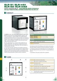
<strong>T2100</strong> <strong>Excitation</strong> <strong>Loss</strong> <strong>Relay</strong><br />
• Protection of generators against loss<br />
of excitation<br />
• Visual indication of power, pick-up<br />
and relay tripping<br />
• High precision digital countdown<br />
timer for delayed output<br />
• Direct Line-Line supply where neutral<br />
is not available<br />
• Accepts high supply voltage variations:<br />
50 - 110%<br />
• Cost effective and highly reliable<br />
compact design<br />
• 50 hours burn-in before final test<br />
• Operating temperature range:<br />
-20°C to +70°C<br />
• Certified by major marine<br />
classification societies<br />
• Flame retardant enclosure<br />
• DIN rail or screw mounting<br />
φ<br />
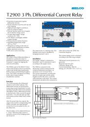
Application<br />
The <strong>T2100</strong> <strong>Excitation</strong> <strong>Loss</strong> <strong>Relay</strong> protects<br />
against partial or complete excitation<br />
loss on the synchronous generator.<br />
If a generator under parallel operation<br />
has a low excitation, a high inductive<br />
current is running into the generator.<br />
This current is detected and the faulty<br />
generator breaker is tripped, thus protecting<br />
the generator, and also avoiding<br />
overload on the remaining generators<br />
with a possible blackout of the system.<br />
Together with the T2000 Reverse Power<br />
<strong>Relay</strong>, the T2500 Overcurrent and Short<br />
Circuit <strong>Relay</strong> and the T2700 Power<br />
<strong>Relay</strong>, the <strong>T2100</strong> provides the optimal<br />
solution for complete generator protection,<br />
both in marine and land-based<br />
applications. The <strong>T2100</strong> is type approved<br />
by major marine classification societies.<br />
Function<br />
The <strong>T2100</strong> measures the voltage across<br />
phases L1 and L2 (or between L1 and<br />
neutral for L-N operation) and the<br />
current through a current transducer<br />
attached on phase L1.<br />
The <strong>T2100</strong> calculates I x sin F, representing<br />
the reactive power. If the reactive<br />
power becomes negative and exceeds<br />
the preset level (0.5 - 1.5 x I N<br />
), the pickup<br />
LED will indicate and the delay<br />
timer will be started.<br />
After the preset time (2 - 20 sec.) has<br />
expired, the output relay and LED will<br />
be activated, provided that the negative<br />
reactive power level was exceeded for<br />
the entire delay time.<br />
The output relay is a latching relay. The<br />
latching can be reset or disabled by<br />
bridging terminals 13 and 14.<br />
Installation<br />
Typical setting is 100% current level.<br />
However, it depends on the type of<br />
generator.<br />
Example of setting:<br />
Required trip level: 100%<br />
Generator rating: 714A<br />
Current transformer: 800/5A<br />
Setting: 1 x 714/800 = 0.9 x I N<br />
It is important that the phase where the<br />
current is measured always is connected<br />
to terminals 1 or 2. See connection<br />
diagram.<br />
For L- L operation terminal 3 is<br />
connected to the next phase in the phase<br />
sequence. For L- N operation terminal 3<br />
is connected to neutral.<br />
It is important that the phase sequence<br />
is correct and the current transformer<br />
side nearest the generator side is<br />
connected to terminal 5.<br />
The LED based pick-up indication is<br />
ideal for testing. The <strong>T2100</strong> can be<br />
tested by reducing the excitation on the<br />
generator, until the pick-up LED<br />
indicates exceeding the preset negative<br />
reactive power level.<br />
Troubleshooting<br />
1) If the relay operates on increased<br />
excitation of motor load, the wiring<br />
to terminals 5 and 6 are interchanged.<br />
2) If the relay is not operating in any<br />
power direction and there is voltage<br />
on terminals 1 and 3 or terminals 2<br />
and 3, check that current is floating in<br />
the current circuit terminals 5 and 6.<br />
3) If the relay trips on different levels<br />
when the test is repeated, or operates<br />
in situations with high motor loads,<br />
check that the voltage and current<br />
inputs have the correct phase<br />
relationship and that the phase<br />
sequence is correct.<br />
4) If the relay trips in situations with<br />
high motor loads, check (as in 3) that<br />
the voltage and current inputs have<br />
the correct phase relationship and<br />
that the phase sequence is correct.<br />
10<br />
7.5<br />
Dimensions.<br />
100<br />
Fixing holes<br />
2 x ø 4,5 mm.<br />
115<br />
85<br />
Dimensions in mm.<br />
70
Specifications<br />
<strong>T2100</strong> <strong>Excitation</strong> <strong>Loss</strong> <strong>Relay</strong><br />
L - L SUPPLY<br />
13<br />
RESET<br />
14<br />
7<br />
8<br />
9 5<br />
10 6<br />
C/B TRIP<br />
C/B TRIP<br />
1<br />
2<br />
3<br />
L - N SUPPLY<br />
13<br />
RESET<br />
14<br />
1<br />
2<br />
3<br />
7<br />
8<br />
9<br />
5<br />
10 6<br />
G<br />
L<br />
1<br />
L<br />
2<br />
L<br />
3<br />
LOAD<br />
G<br />
L<br />
1<br />
L<br />
2<br />
L<br />
3<br />
N<br />
LOAD<br />
Connection diagram. <strong>Relay</strong> shown de-energized.<br />
Type Approvals and Certificates<br />
The <strong>T2100</strong> has been designed and tested<br />
for use in harsh environments. The<br />
<strong>T2100</strong> carries the CE label and has been<br />
approved by the following marine<br />
classification societies:<br />
Bureau Veritas<br />
Romanian Register of Shipping<br />
Russian Maritime Register of Shipping<br />
Trip level<br />
Delay<br />
Max. voltage<br />
0.5 - 1.5 x I N<br />
2 - 20 sec.<br />
660V<br />
Voltage range 50 - 110%<br />
Consumption<br />
Continuous current<br />
Frequency range<br />
Output relay<br />
Contact rating<br />
Overall accuracy ±5%<br />
Repeatability ±1%<br />
Operating temperature<br />
Dielectric test<br />
EMC<br />
Approvals<br />
Burn-in<br />
Enclosure material<br />
Weight<br />
Voltage 5VA at U N<br />
Current 0.3VA at I N<br />
2 x I N<br />
45 - 400Hz<br />
Normally de-energized, latching, resetable<br />
AC: 400V, 5A, 1250VA<br />
DC: 150V, 5A, 120W<br />
-20°C to +70°C<br />
2500V, 50Hz<br />
CE according to EN50081-1, EN50082-1, EN50081-2,<br />
EN50082-2<br />
Certified by major marine classification societies<br />
50 hours before final test<br />
Polycarbonate. Flame retardant<br />
0.5kg<br />
Dimensions 70 x 100 x 115mm (H x W x D)<br />
Installation<br />
35mm DIN rail or 4mm (3/16”) screws<br />
The specifications are subject to change without notice.<br />
Type Selection Table<br />
Standard types: I N<br />
= 5A<br />
Terminals<br />
Type 1-3 2-3 I N<br />
Supply Function<br />
<strong>T2100</strong>.0010 230V 5A L-N<br />
<strong>T2100</strong>.0020 480V 415V 5A L-L<br />
<strong>T2100</strong>.0030 450V 400V 5A L-L<br />
<strong>T2100</strong>.0040 110V 100V 1A L-L<br />
<strong>T2100</strong>.0050 110V 100V 5A L-L<br />
<strong>T2100</strong>.0060 110V 100V 5A L-L Current 0.2 - 1.2 x I N<br />
<strong>T2100</strong>.0070 480V 415V 5A L-L Normally energized output,<br />
current 0.05 - 0.15 x I N<br />
<strong>T2100</strong>.0080 110V 100V 5A L-L 24V DC aux. voltage supply,<br />
current 0.2 - 1.2 x I N<br />
Other combinations and voltages are available on request.<br />
Main office:<br />
SELCO A/S<br />
Betonvej 10<br />
DK-4000 Roskilde<br />
Denmark<br />
Phone: + 45 7026 1122<br />
Fax: + 45 7026 2522<br />
e-mail: selco.dk@selco.com<br />
www.selco.com<br />
T2195-51E