Lecture handout including QS - Department of Materials Science ...
Lecture handout including QS - Department of Materials Science ...
Lecture handout including QS - Department of Materials Science ...

You also want an ePaper? Increase the reach of your titles
YUMPU automatically turns print PDFs into web optimized ePapers that Google loves.
Natural <strong>Science</strong>s Tripos Part IA<br />
MATERIALS SCIENCE<br />
Course B: <strong>Materials</strong> for Devices<br />
Name............................. College..........................<br />
Dr Zoe Barber<br />
Michaelmas Term 2013-14<br />
14<br />
IA
Contents<br />
Introduction<br />
1<br />
Magnetic <strong>Materials</strong><br />
36<br />
Synopsis<br />
2<br />
Diamagnetism, Paramagnetism<br />
36<br />
Text Books & Websites<br />
3<br />
Ferro-, Antiferro-, Ferrimagnetism<br />
37<br />
Ferromagnetic <strong>Materials</strong><br />
38<br />
Liquid Crystals<br />
4<br />
Curie temperature<br />
38<br />
Nematic Liquid Crystal structure<br />
4<br />
Magnetocrystalline anisotropy<br />
38<br />
Polarized Light<br />
6<br />
Domain formation<br />
38<br />
Birefringence & Polarized Light Microscopy<br />
8<br />
Shape Anisotropy<br />
39<br />
The Michel-Levy Chart<br />
10<br />
Magnetostriction<br />
39<br />
Extinction Positions &<br />
Domain wall, Bloch wall<br />
39<br />
Permitted Vibration Directions<br />
11<br />
Ferromagnetic Hysteresis<br />
40<br />
Determination <strong>of</strong> Sign <strong>of</strong> Birefringence<br />
11<br />
Aside on magnetic parameters<br />
42<br />
Birefringence in Liquid Crystals<br />
11<br />
Hysteresis loops: hard versus s<strong>of</strong>t<br />
42<br />
Further types <strong>of</strong> Liquid Crystals:<br />
Ferrimagnetism & Spinel Structure<br />
43<br />
Smectic & Chiral Nematic<br />
12<br />
Inverse Spinel Structure<br />
43<br />
Liquid Crystal Displays<br />
14<br />
Solid Ionic Conducting <strong>Materials</strong><br />
44<br />
An Introduction to Polymer Structures<br />
16<br />
(a) Diffusion Current<br />
45<br />
Flexible chains: conformation<br />
17<br />
(b) Drift Current<br />
46<br />
How big is a polymer molecule<br />
19<br />
Nernst-Einstein Equation<br />
46<br />
Examples <strong>of</strong> common polymers<br />
20<br />
Solid State Ionic Conductors<br />
48<br />
Polymer Microstructure & Properties<br />
21<br />
Yttrium Stabilized Zirconia, YSZ<br />
48<br />
Crystallinity<br />
22<br />
δ-Bi 2 O 3<br />
48<br />
Applications<br />
49<br />
Dielectric Properties <strong>of</strong> <strong>Materials</strong><br />
23<br />
1. Oxygen Concentration cell<br />
49<br />
Polarisation Mechanisms<br />
23<br />
Lambda Sensor<br />
50<br />
Polarisation & Capacitance<br />
23<br />
2. Oxygen Pump<br />
51<br />
Dipole formation & Symmetry<br />
25<br />
3. Fuel Cell<br />
51<br />
Piezoelectrics<br />
27<br />
The hydrogen economy<br />
53<br />
Pyroelectrics<br />
28<br />
Ferroelectrics<br />
29<br />
Glossary<br />
54<br />
Polarisation & Structure<br />
29<br />
Phase Transitions in BaTiO 3<br />
30<br />
Switchable Dipoles<br />
31<br />
Dipole ordering & Domains<br />
32<br />
Reversible Polarisation, hysteresis<br />
33<br />
Applications, memory device<br />
34<br />
PZT<br />
35
BH1 Course B: <strong>Materials</strong> for Devices BH1<br />
Course B: <strong>Materials</strong> for Devices<br />
The functional properties <strong>of</strong> materials, such as magnetism, polarization and conduction, are intimately<br />
related to their crystal structure. Furthermore, many <strong>of</strong> these properties are also anisotropic –<br />
meaning that they are dependent upon the specific direction within a crystal structure. It is imperative<br />
that we understand these structure–property links in order to understand fully materials properties,<br />
and be able to control and optimize these properties. Only through such an understanding can we<br />
hope to exploit the full range <strong>of</strong> possible device and materials applications, keep coming up with<br />
smaller and smaller music systems, faster computers, and overcome some <strong>of</strong> the environmental issues<br />
currently troubling the world.<br />
The course begins with the remarkable properties <strong>of</strong> Liquid Crystals: somewhere between liquids<br />
(isotropic, no long range order) and crystals (anisotropic and ordered). The anisotropy <strong>of</strong> liquid<br />
crystals leads to important optical effects, which are exploited in display technology.
BH2 Course B: <strong>Materials</strong> for Devices BH2<br />
Synopsis <strong>of</strong> Course B<br />
1. Liquid Crystals & Polarized Light: rigid polymer molecules, nematic structures, the order<br />
parameter. Plane polarized light and birefringence. Permitted vibration directions, optical path<br />
difference & phase difference, Polarized Light Microscopy.<br />
2. Birefringence in Liquid Crystals: the Michel-Levy chart, extinction positions, compensators.<br />
Schlieren texture and disclinations. Smectic and chiral / cholesteric liquid crystals. Liquid Crystal<br />
Displays.<br />
3. An Introduction to Polymer Structure: repeated monomer units, long chain molecules,<br />
methods <strong>of</strong> representation. Conformation, flexibility, molecular size. Side groups, tacticity,<br />
microstructure & properties. Crystallinity in polymers.<br />
4. Dielectrics: polarisation mechanisms, permittivity & dielectric constant, capacitance. Symmetry &<br />
properties.<br />
5. Polarisation; Piezo-, and Pyro-electrics: Piezoelectric motor & generator effect, pyroelectric<br />
applications.<br />
6. Ferroelectricity: polarisation & structure, switching, phase transitions in BaTiO 3<br />
. Dipole<br />
ordering & domains, domain walls, poling.<br />
7. Ferroelectric Hysteresis & Applications: domain reversal & hysteresis loops. FE memory<br />
devices, materials requirements. PZT phase diagram.<br />
8. The Origin <strong>of</strong> Magnetism: electron orbitals & spin; dia-, para-, ferro-, antiferro- & ferrimagnetism.<br />
Magnetocrystalline anisotropy, domain formation, shape anisotropy, magnetostriction.<br />
9. Ferromagnets: domains and domain walls, ferromagnetic hysteresis. Tailoring magnetic<br />
properties for applications. Ferrimagnetism: the spinel & inverse spinel structures & magnetite.<br />
10. Solid Ionic Conducting <strong>Materials</strong>: conduction in solids, vacancy mediated ion hopping,<br />
activation energy, ion flux. Diffusion current (concentration gradient) & drift current (electric field).<br />
11. Solid State Ionic Conductors: the Nernst-Einstein equation. Arrhenius plots and ion<br />
conductivity. Yttrium stabilized zirconia, formation <strong>of</strong> oxygen vacancies. Oxygen concentration cell.<br />
12. Applications <strong>of</strong> Ionic Conductors: Lambda sensor, oxygen pump, fuel cells. <strong>Materials</strong><br />
requirements, the hydrogen economy.
BH3 Course B: <strong>Materials</strong> for Devices BH3<br />
Recommended Text Books & Websites<br />
Parts <strong>of</strong> the following may be helpful:<br />
Basic Solid State Chemistry A R West (Wiley, 2 nd edition) Pq62, and Pq62a Tripos Ref.<br />
For polymers and liquid crystals –<br />
Liquid Crystalline Polymers A Donald, A Windle & S Hanna (C.U.P., 2 nd edition) AN6b.140,<br />
AN6c.140, and AN6c.140a Tripos Ref.<br />
Physical Properties <strong>of</strong> Polymers James Mark et al (C.U.P., 3 rd edition) AN6c.135<br />
Liquid Crystals Peter J Collings (I.O.P. Publishing, 2 nd edition) Ng134a, and Ng134b Tripos Ref.<br />
Dielectrics, polarisation, conduction, magnetism, ceramics –<br />
Electroceramics A J Moulson & J M Herbert (Wiley, 2 nd edition) AN2a.111<br />
Introduction to Ceramics W D Kingery, H K Bowen & D R Uhlmann (Wiley, 2 nd ed.) AN2a.13,<br />
and AN2a.13a Tripos Ref.<br />
More general interest –<br />
<strong>Materials</strong> <strong>Science</strong> and Engineering W D Callister (John Wiley, 2003, 6 th ed.) AB168a, and AB168<br />
Tripos Ref.<br />
Introduction to <strong>Materials</strong> <strong>Science</strong> J P Mercier, G Zambelli & W Kurz (Elsevier) AB218b, and<br />
AB218a Tripos Ref.<br />
Also, many <strong>of</strong> the DoITPoMS Teaching & Learning Packages:<br />
Introduction to Anisotropy<br />
Atomic Scale Structure <strong>of</strong> <strong>Materials</strong><br />
(see Single Crystals: Optical Properties)<br />
Crystallinity in Polymers<br />
Crystallography<br />
Dielectric <strong>Materials</strong><br />
Diffusion<br />
Ferroelectric <strong>Materials</strong><br />
Ferromagnetic <strong>Materials</strong><br />
Fuel Cells<br />
Lattice Planes and Miller Indices<br />
Liquid Crystals<br />
Optical Microscopy (look at Polarised Light)<br />
Introduction to Photoelasticity<br />
Piezoelectric <strong>Materials</strong><br />
Pyroelectric <strong>Materials</strong><br />
Polymer Basics<br />
http://plc.cwru.edu Resources related to Polymers and Liquid Crystals.<br />
Crystal Maker S<strong>of</strong>tware: see link on website for this course.
BH4 Course B: <strong>Materials</strong> for Devices BH4<br />
Liquid Crystals<br />
• Crystalline materials have long-range order. This means that they are anisotropic: their properties<br />
(e.g. refractive index, thermal expansion coefficient, electrical conductivity) may differ, depending<br />
upon the direction <strong>of</strong> measurement.<br />
• In contrast, liquids, which have no long-range order, are isotropic: they are invariant with respect<br />
to direction. The absence <strong>of</strong> long-range order means that all directions are equivalent.<br />
• Somewhere in between there are Liquid Crystals, which are anisotropic liquids. Their anisotropy,<br />
or directionality, comes from molecular shape.<br />
Liquid crystals <strong>of</strong>ten consist <strong>of</strong> rod-shaped molecules, with a rigid long axis:<br />
e.g. Methoxybenzylidene Butylaniline, or MBBA<br />
The central region <strong>of</strong> the<br />
molecule (between the<br />
rings) is rigid, whilst the<br />
ends are flexible.<br />
These rod-shaped<br />
molecules are free to<br />
move relative to each<br />
other and flow past<br />
each other, so that<br />
there is no long-range<br />
positional order.<br />
However, because <strong>of</strong> their shape, they tend to line up, with their long axes lying roughly parallel, i.e.<br />
they have some orientational order. This alignment stems from packing considerations, and also<br />
electrostatic interactions.<br />
Nematic Liquid Crystal (LC) structure<br />
No positional order.<br />
Long range orientational order, defined by a<br />
Director, D.<br />
D<br />
This leads to useful anisotropic optical<br />
properties, which are the basis for electronic<br />
displays.
BH5 Course B: <strong>Materials</strong> for Devices BH5<br />
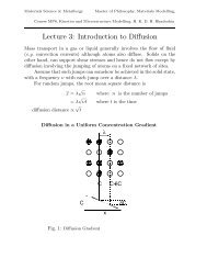
The degree <strong>of</strong> orientational order in a LC is temperature dependent:<br />
• at high temperature thermal agitation overcomes the alignment interaction, leading to randomisation<br />
<strong>of</strong> the molecular orientation, i.e. the liquid crystal becomes a ‘normal’ isotropic liquid.<br />
• at low temperature the system may crystallise into a ‘normal’ crystal structure.<br />
crystal liquid crystal liquid<br />
Director, D<br />
highly ordered,<br />
no intrinsic order,<br />
no translational freedom<br />
increasing temperature,<br />
isotropic<br />
decreasing order<br />
An order parameter, Q, is used to describe the degree <strong>of</strong> orientational order.<br />
Q = 3 cos2 θ −1<br />
2<br />
Director, D<br />
θ<br />
where<br />
.... represents an average over all molecules.<br />
With all molecules aligned:<br />
cos 2 θ = 1 ⇒<br />
Q = 1<br />
For an isotropic liquid, with randomly oriented molecules: cos 2 θ = 1 €<br />
3 ⇒ Q = 0<br />
€ €<br />
Consider a hemisphere:<br />
The probability <strong>of</strong> the molecule lying at an angle, € θ, is proportional € to<br />
the circumference, 2πr = 2πd sinθ r<br />
(Higher angles are more likely.)<br />
A small increment in angle, dθ , corresponds to a d<br />
surface area <strong>of</strong> 2πr × d × dθ = 2πd sinθ d dθ<br />
To calculate cos 2 θ , we integrate over the surface <strong>of</strong><br />
the hemisphere (from θ = 0 to π / 2 ), and divide by the<br />
total surface area (for the hemisphere, this is 2πd 2 ):<br />
∫<br />
0<br />
π 2<br />
cos 2 θ 2πd sinθ d dθ<br />
= − 1 π<br />
⎡⎡ ⎤⎤ 2<br />
2πd 2 3 cos3 θ<br />
⎣⎣<br />
⎢⎢<br />
⎦⎦<br />
⎥⎥ = 1 3<br />
0<br />
€
BH6 Course B: <strong>Materials</strong> for Devices BH6<br />
Polarized Light<br />
Light is a transverse electromagnetic wave with an electric field, E, oscillating in a direction orthogonal<br />
to the propagation direction:<br />
The direction <strong>of</strong> polarization refers to the<br />
vibration axis <strong>of</strong> the E field. The plane <strong>of</strong><br />
polarization is the plane containing the<br />
vibration axis and the direction <strong>of</strong> propagation.<br />
The wave sketched here is called a plane wave,<br />
since the vibration axis is always in the same<br />
plane.<br />
polarization direction<br />
(In unpolarized light the field vibrates in all<br />
directions perpendicular to the direction <strong>of</strong><br />
propagation.)<br />
Light passing through a sample:<br />
Electromagnetic waves passing through a polymer sample couple to electron density in the polymer<br />
molecules. Light incident upon a polymer molecule will couple strongly (have a larger interaction) in<br />
one vibration direction and weakly in the perpendicular direction.<br />
In an isotropic polymer sample (e.g. at high temperature,<br />
in the liquid state) the molecules are randomly aligned,<br />
and hence there will be no net effect upon the polarization<br />
<strong>of</strong> the transmitted light.<br />
However, if the polymer molecules are preferentially<br />
aligned (i.e. the polymer is anisotropic, as in a nematic<br />
LC), there will be one direction in the sample along which<br />
the vibration vector couples strongly (called the slow axis,<br />
since the light will be slowed down most significantly)<br />
and another, perpendicular, direction in which it couples<br />
The isotropic state:<br />
no orientational order<br />
weakly (called the fast axis, since the light is slowed down less). These two directions, which are both<br />
perpendicular to the direction <strong>of</strong> propagation, are called permitted vibration directions (PVDs).<br />
Since the speed <strong>of</strong> light in the material, v, is different in these 2 directions, the refractive index, n, is<br />
different along the 2 perpendicular vibration directions in the material:<br />
n = c v
BH7 Course B: <strong>Materials</strong> for Devices BH7<br />
Depending upon the structure <strong>of</strong> a polymer molecule, the slow direction may be along the length <strong>of</strong><br />
the molecule, or perpendicular to the length. e.g. (for light propagating perpendicular to the plane <strong>of</strong><br />
the paper):<br />
→ n 1<br />
↓ n 2<br />
polyethylene polystyrene<br />
€<br />
n 1<br />
> n 2 fast<br />
n 1<br />
< n 2<br />
slow<br />
slow<br />
fast<br />
The birefringence is defined as the difference between the refractive indices:<br />
Δn = n 1<br />
− n 2<br />
Whether or not a polymer sample exhibits non-zero birefringence will depend on the degree <strong>of</strong> chain<br />
orientation:<br />
random, isotropic = non-birefringent<br />
aligned (or crystalline), anisotropic = birefringent. €<br />
Polarizers or Polaroid materials are used as polarizing filters to produce linear polarized light.<br />
These are polymer films (e.g. polyvinyl alcohol, PVOH, doped with iodine), in which the long-chain<br />
polymer molecules are uniaxially aligned. The molecules absorb light vibrating parallel to their long<br />
axes, and transmit that vibrating perpendicular:<br />
[ Note: the lines<br />
drawn to illustrate a<br />
polarizer generally<br />
indicate the resultant<br />
direction <strong>of</strong> polarization<br />
<strong>of</strong> the light,<br />
rather than the<br />
alignment <strong>of</strong> the<br />
absorbing structure.]<br />
Direction <strong>of</strong> alignment<br />
<strong>of</strong> polymer molecules ↓<br />
Crossed polars:<br />
(all light will be blocked)<br />
polarizer<br />
analyzer
BH8 Course B: <strong>Materials</strong> for Devices BH8<br />
Birefringence and Polarized Light Microscopy<br />
Light passing into an optically anisotropic, or birefringent, material is resolved into two components,<br />
along the two permitted vibration directions (PVDs): fast (lower n), with its vibration direction parallel<br />
to the fast direction in the material, and slow (higher n), with its vibration direction parallel to the<br />
slow direction. For example, plane polarized light entering a sample:<br />
A Polarizer defines<br />
the direction <strong>of</strong><br />
polarization <strong>of</strong> the<br />
incident light<br />
2 perpendicular<br />
PVDs in sample<br />
The fast component (lower n) travels faster than the slow component (higher n)! Hence, the two<br />
components take different times to reach the end <strong>of</strong> the sample. Or, put another way, there is an<br />
optical path difference (o.p.d.) between them:<br />
Direction <strong>of</strong><br />
polarization <strong>of</strong><br />
incident light (at 45°<br />
to vertical axis)<br />
o.p.d. = Δn.t<br />
€<br />
As illustrated above, this difference in speed between the fast and slow components leads to a phase<br />
δ<br />
difference, δ, between the light in these two vibration directions:<br />
2π = Δn.t<br />
λ
BH9 Course B: <strong>Materials</strong> for Devices BH9<br />
Let’s think about viewing a sample which is placed between crossed polars. When the slow and fast<br />
components exit the sample and recombine, the vibration direction <strong>of</strong> the resultant wave depends<br />
upon the relative phase difference between them.<br />
• if the optical path difference is λ / 2 , the phase difference will be π, and the direction <strong>of</strong> polarization<br />
will be exactly perpendicular to the original:<br />
Po<br />
polarized incident<br />
light (45° to vertical)<br />
Allowed polarization<br />
direction <strong>of</strong> Analyzer, placed<br />
o.p.d. is exactly half<br />
at 90° to Polarizer, after light a wavelength<br />
has passed through sample.<br />
Viewing through crossed polars, light will pass through the Analyzer<br />
• if the optical path difference is λ, e.g. if the birefringence is greater (see (a) below); or the<br />
wavelength is shorter (b); or the sample is thicker (c), the phase difference will be 2π (which is<br />
equivalent to no phase difference at all), and the direction <strong>of</strong> polarization will be the same as the<br />
original. For crossed polars, this means that no light passes through the analyzer.<br />
(a) (b)<br />
(c)<br />
o.p.d. is exactly one wavelength<br />
(or an integral<br />
number <strong>of</strong> wavelengths).
BH10 Course B: <strong>Materials</strong> for Devices BH10<br />
Remember - the phase difference is dependent upon the birefringence <strong>of</strong> the sample, the wavelength<br />
<strong>of</strong> the light, and the sample thickness:<br />
δ<br />
2π = Δn.t<br />
λ<br />
Look at a sample between crossed polars (polarizer ⊥ r analyzer):<br />
• if section is isotropic (non-birefringent), no light will be transmitted through the analyzer.<br />
• if sample is birefringent, and the optical path difference is an integral number <strong>of</strong> wavelengths,<br />
Nλ, then there will be zero phase difference between the 2 components, the plane <strong>of</strong> polarization<br />
will be unchanged, and hence no light <strong>of</strong> wavelength λ will be transmitted.<br />
⇒ if a birefringent sample is illuminated with white (i.e. polychromatic) light, one wavelength <strong>of</strong><br />
that light will be lost through the condition described above. Therefore the light observed will<br />
consist <strong>of</strong> the full optical spectrum minus that specific wavelength (the complementary colour).<br />
The colour will depend upon the birefringence and the thickness <strong>of</strong> the sample:<br />
The Michel-Levy chart<br />
Very low retardation:<br />
(very thin section, or very<br />
low birefringence).<br />
→<br />
→<br />
Move through higher<br />
‘orders’ <strong>of</strong> colours as<br />
o.p.d. = λ, 2λ, 3λ etc.<br />
High retardation: several different wavelengths<br />
are ‘lost’ (with different integer values, e.g.<br />
o.p.d. = 2λ 2 = 3λ 1 ), & colours become washed out<br />
•<br />
•<br />
•<br />
•<br />
•<br />
•<br />
•<br />
•<br />
•<br />
•<br />
•<br />
Retardation = optical path difference = Δn × t
BH11 Course B: <strong>Materials</strong> for Devices BH11<br />
Extinction positions and Permitted Vibration Directions<br />
If the incident light has its plane <strong>of</strong> polarization parallel to one <strong>of</strong> the permitted vibration directions in<br />
a birefringent sample, then there will only be light transmitted through the sample in this one vibration<br />
direction. Hence there are not 2 components <strong>of</strong> the light travelling through the sample, and there<br />
can be no phase difference. The emerging light will have the same plane <strong>of</strong> polarization as it had<br />
originally and, between crossed polars, no light will be transmitted.<br />
The sample will appear black, and this is called<br />
an extinction position.<br />
By rotating a sample between crossed<br />
polars in order to find this condition,<br />
the permitted vibration<br />
directions <strong>of</strong> the sample<br />
can be determined.<br />
Samples are best observed<br />
with their PVDs at 45° to<br />
the polarizer / analyzer.<br />
Determination <strong>of</strong> the sign <strong>of</strong> the birefringence (i.e. which direction is fast, and which is slow)<br />
This is done by adding a compensator: an optically anisotropic crystal with a known birefringence<br />
(e.g. quartz), to the light path. With both the sample and compensator aligned such that their PVDs<br />
are at 45° to the polarizer / analyzer, there are 2 possible situations:<br />
ADDITION: fast direction <strong>of</strong> compensator is parallel to fast direction <strong>of</strong> unknown sample<br />
⇒ total optical path difference increases, & observed colour will be higher in the Michel Levy chart.<br />
SUBTRACTION: fast direction <strong>of</strong> compensator is parallel to slow direction in unknown sample,<br />
⇒ total optical path difference decreases, & observed colour will be lower in the Michel Levy chart.<br />
Birefringence in Liquid Crystals<br />
Light passing through a sample <strong>of</strong> nematic Liquid Crystal is resolved into two components:<br />
slow<br />
The permitted vibration directions are parallel and<br />
perpendicular to the director, D.<br />
↑<br />
D<br />
fast<br />
e.g. light vibrating parallel to the director<br />
(principally along the long axes <strong>of</strong> the molecules)<br />
may have a larger refractive index than that<br />
vibrating in the perpendicular direction. This means<br />
that it would travel slower.<br />
Note: if the direction <strong>of</strong> propagation is parallel to the Director (i.e. along the optic axis <strong>of</strong> the<br />
sample), then the section is isotropic (and hence non-birefringent).
BH12 Course B: <strong>Materials</strong> for Devices BH12<br />
A sample <strong>of</strong> nematic LC will not necessarily have a single, uniform director across its whole volume,<br />
but instead may be broken down into smaller, differently oriented regions, or domains.<br />
Where differently oriented domains meet there is<br />
a ‘glitch’, called a disclination. Observation <strong>of</strong> a<br />
LC sample between crossed polars typically<br />
shows a schlieren texture: bright regions <strong>of</strong><br />
nematic LC with uniform director, separated by<br />
dark boundary regions where the director is<br />
aligned with the polarizer or analyzer (or is<br />
parallel to the light path), and hence the sample is<br />
in extinction.<br />
Further types <strong>of</strong> Liquid Crystals<br />
There are several different classes <strong>of</strong> LC, based upon their overall tendency for molecular alignment.<br />
Smectic: molecules organise into layers<br />
⇒ orientational order, some positional order<br />
Chiral nematic: helical twist<br />
Smectic A<br />
D parallel to<br />
layer normal<br />
Smectic C<br />
↑<br />
D<br />
D<br />
D<br />
The molecules in a Chiral Nematic (also called cholesteric) have their long axes (and hence director)<br />
in a plane (in the above, this is shown as the horizontal); the director rotates along the axis perpendicular<br />
to this plane, tracing out a helix. For polarized light propagating along this axis, the plane <strong>of</strong><br />
polarization rotates with D. The pitch is the distance along the axis taken for a complete 360° rotation<br />
<strong>of</strong> the director. It can vary over a very wide range, e.g. ~100 nm - 100 µm, depending upon the LC<br />
molecules involved, the degree <strong>of</strong> polymerization, and the concentration in solution.
BH13 Course B: <strong>Materials</strong> for Devices BH13<br />
This twisted structure occurs because the molecules are chiral (lack inversion symmetry) [see AH68],<br />
and show an asymmetric packing preference.<br />
e.g. Poly(γ-benzyl-L-glutamate) (PBLG):<br />
with R:<br />
Monomer:<br />
Polymer:<br />
The polymer molecule is an α-helix, i.e. is asymmetric (there’s a difference between a right-hand and<br />
a left-hand helix). This leads to the observed twist in alignment, i.e. twist <strong>of</strong> the director.<br />
dark →<br />
(light propagation<br />
along<br />
symmetry axis<br />
<strong>of</strong> molecules<br />
⇒ nonbirefringent)<br />
Observation <strong>of</strong> a chiral nematic LC between crossed<br />
polars, with light travelling perpendicular to the axis <strong>of</strong><br />
the helix, shows a stripy pattern, <strong>of</strong>ten appearing like a<br />
fingerprint:<br />
dark →<br />
strongly<br />
birefringent<br />
⇒ bright
BH14 Course B: <strong>Materials</strong> for Devices BH14<br />
In another example <strong>of</strong> a chiral molecule, the steepness <strong>of</strong> the twist decreases (i.e. the pitch increases)<br />
as m increases, and the chiral centre (the asymmetric, or ‘handed’ part <strong>of</strong> the molecule) moves away<br />
from the mesogenic core (the ‘stiff’ part <strong>of</strong> the molecule):<br />
mesogenic core<br />
chiral centre<br />
i.e. a long molecule will be ‘less’ asymmetric, have little angular twist with its neighbours, &<br />
therefore have a long pitch.<br />
- a shorter molecule → strongly asymmetric → steeper twist (larger angle between neighbours), &<br />
Liquid Crystal Displays<br />
hence a short pitch.<br />
The director <strong>of</strong> a nematic LC can be encouraged to lie along a particular direction by creating grooves<br />
on a surface in contact with it (this is generally done with an aligned polymer coating; but in one <strong>of</strong><br />
the samples in BP1 parallel scratches were made with fine emery paper). The LC molecules will tend<br />
to lie along the length <strong>of</strong> the grooves. If the LC is sandwiched between 2 glass plates, with grooves at<br />
90° to each other, the molecules (and hence the director) will twist across the sandwich, resulting in a<br />
precisely defined twisted nematic structure:<br />
Viewed from the top<br />
In order to achieve this a small amount <strong>of</strong> chiral nematic dopant is generally added to the LC.<br />
Polarized light entering the bottom <strong>of</strong> the<br />
sandwich has its plane <strong>of</strong> polarization twisted<br />
through 90° as it reaches the top. If the<br />
polarizer and analyzer are parallel to the<br />
grooves at the bottom and the top, respectively,<br />
light will be transmitted through the LC cell:<br />
the ON state.
BH15 Course B: <strong>Materials</strong> for Devices BH15<br />
Application <strong>of</strong> an electric field across the LC cell<br />
affects the orientation <strong>of</strong> the molecules. There is charge<br />
separation (the opposite ends <strong>of</strong> the molecule develop<br />
opposite charges: an induced dipole moment) and, as a<br />
result, the molecules tend to line up along the field<br />
direction, i.e. perpendicular to the original plane <strong>of</strong><br />
polarization. This is called the Freedericksz transition.<br />
Although the molecules near the grooved surfaces<br />
maintain their orientation parallel to the grooves, those<br />
molecules towards the centre <strong>of</strong> the cell become<br />
oriented parallel to the applied field. Hence, the<br />
twisting <strong>of</strong> the plane <strong>of</strong> polarization is disrupted, and light cannot be transmitted through the cell:<br />
the OFF state.<br />
Light enters through the front <strong>of</strong> the display and is reflected from the back mirror. In front <strong>of</strong> the<br />
mirror are a polarizing filter, a ‘back’ (transparent) common electrode, and the twisted nematic LC<br />
cell. Light coming out <strong>of</strong> the front <strong>of</strong> the cell will have had its plane <strong>of</strong> polarization twisted through<br />
90° from the polarizer, and this can pass through the analyzer. Shaped electrodes between the cell<br />
and the analyzer can be independently powered: if powered, then the LC in the specific region<br />
between the two electrodes will untwist and block the light.<br />
In a colour display there is fluorescent backlighting, and colour filters create red, green and blue subpixels.
BH16 Course B: <strong>Materials</strong> for Devices BH16<br />
An Introduction to Polymer Structures<br />
Polymers consist <strong>of</strong> large molecules, or macromolecules, which are built up from repeating smaller<br />
structural units, or monomers. The number <strong>of</strong> repeated units in a polymer molecule may be <strong>of</strong> order<br />
100 – 10,000. This can lead to very long chain molecules, e.g. up to several microns, although the<br />
chains are generally twisted and coiled up, rather than stretched out lengthwise. In addition to linear<br />
chains, polymer molecules may be branched or cross-linked.<br />
Polyethylene, or polythene (C 2<br />
H 4<br />
) n<br />
, is the simplest example:<br />
Monomer unit:<br />
Polyethylene chain:<br />
However, this representation can be misleading, since molecules are 3-dimensional structures. The<br />
bonds from a carbon atom are oriented in an approximately tetrahedral arrangement:<br />
2.5 Å<br />
Space-filling models give, perhaps, an even more realistic representation, although it may be difficult<br />
to visualise the bond angles:<br />
Monomer unit:<br />
Section <strong>of</strong> chain:
BH17 Course B: <strong>Materials</strong> for Devices BH17<br />
Flexible chains: conformation<br />
Chains are not rigid, but can twist and rotate.<br />
Rotation about the C-C bonds leads to<br />
changes in conformation.<br />
In polyethylene the lowest energy<br />
conformation (called trans) has neighbouring<br />
C-C bonds “staggered”:<br />
… the highest energy conformation<br />
has the C-C bonds aligned:<br />
The bonds from adjacent C atoms are misaligned,<br />
with the subsequent C atoms in the<br />
chain as far apart as they can be.<br />
There are 2, equivalent, intermediate energy conformations (called gauche), with the bonds<br />
misaligned, but the subsequent C atoms closer than in trans:<br />
A plot <strong>of</strong> the energy <strong>of</strong> all<br />
possible conformations<br />
looks like this:<br />
high energy states<br />
between minima<br />
low energy conformations<br />
at minima
BH18 Course B: <strong>Materials</strong> for Devices BH18<br />
A polyethylene chain with all bonds in the (lowest energy) trans conformation will look like this:<br />
But, in reality, it will typically have a range <strong>of</strong> different conformations, which lead to twisting and<br />
coiling:<br />
2.5 Å<br />
5 Å<br />
20 nm<br />
The energy increase associated with non-trans conformations and, in particular, the energy barrier<br />
required to change conformation, means that increased thermal energy (i.e. increased temperature)<br />
leads to a higher probability <strong>of</strong> conformational changes (i.e. chain rotation) taking place. At higher<br />
temperatures polymer molecules become more flexible, and can twist, coil and uncoil around each<br />
other. At lower temperatures they are unable to flex. This temperature scale depends upon the<br />
polymer molecules concerned (depending upon their structure, some are ‘stiffer’ than others).
BH19 Course B: <strong>Materials</strong> for Devices BH19<br />
How big is a polymer molecule<br />
A polymer chain can be modelled as a series <strong>of</strong> shorter, rigid segments (each <strong>of</strong> length l ) that can<br />
rotate freely where they join.<br />
“Random walk”:<br />
r 1<br />
• If the chain consists <strong>of</strong> n segments, and it<br />
were stretched out straight, its length, L, would<br />
be nl.<br />
• end-to-end vector,<br />
• A useful measure <strong>of</strong> the size <strong>of</strong> the polymer molecule is given by the<br />
<br />
2<br />
root mean square <strong>of</strong> R n<br />
: R n<br />
€ €<br />
r n-1<br />
r 2<br />
r 3 r 4<br />
R n -1<br />
R n<br />
r n<br />
€<br />
also,<br />
<br />
R n<br />
=<br />
<br />
R n−1<br />
=<br />
n<br />
<br />
∑ and<br />
• The average value € <strong>of</strong> the end to end vector,<br />
<br />
R n<br />
, is zero: R n<br />
= 0<br />
€<br />
i=1<br />
r i<br />
<br />
n−1<br />
∑r i<br />
i=1<br />
<br />
R n<br />
= R <br />
n−1<br />
+ r <br />
n<br />
1 2<br />
where γ is the angle between the vector<br />
R 2 n<br />
= ( R n−1<br />
+ r n ) ⋅ <br />
Rn−1 + r n<br />
€ 2<br />
= R n−1<br />
+ € 2R n−1<br />
× l cosγ<br />
( ) = R 2<br />
n−1<br />
( ) + l 2<br />
The average value <strong>of</strong> cosγ must be zero, and therefore,<br />
( ) + r n<br />
+ 2 R n−1<br />
⋅ r n<br />
and the last segment,<br />
<br />
R n<br />
2<br />
2<br />
= R 2<br />
n−1<br />
€ = R 2<br />
n−2<br />
<br />
r n<br />
+ l 2<br />
€<br />
+ l 2 + l 2 etc.<br />
<br />
R n−1<br />
And, by induction:<br />
mean square end-to-end distance,<br />
R n<br />
2<br />
= nl 2<br />
root mean square,<br />
R n<br />
2<br />
1 2<br />
= n 1 2<br />
l<br />
We might assume that each segment <strong>of</strong> the chain, € l, corresponds to a single C-C bond. But such<br />
segments can never be completely freely jointed (bond angles are limited, and adjacent segments can<br />
simply get in the way <strong>of</strong> each other). € Hence real polymer chains are always stiffer than shown by this<br />
model using a single C-C bond as a segment length, and their stiffness is dependent upon the nature<br />
<strong>of</strong> the monomer units involved.<br />
The model can be used more generally if we define l, the segment length, as the length scale below<br />
which the chain is effectively straight and rigid – this is called the Kuhn length. The simple<br />
polyethylene structure has a Kuhn length <strong>of</strong> about 3.5 times the C-C bond length, whilst polystyrene,<br />
which has more bulky side-groups, has a Kuhn length <strong>of</strong> 5 × C-C (it’s stiffer).
BH20 Course B: <strong>Materials</strong> for Devices BH20<br />
A few examples <strong>of</strong> common polymers with different side-groups:<br />
Monomer<br />
Polyvinylchloride (PVC)<br />
Polypropylene<br />
Polystyrene<br />
The side-groups (Cl, or CH 3 , or C 6 H 5 in the above examples) may be arranged in different ways<br />
along the chain, which defines the molecule’s configuration, or tacticity. Considering the chain in the<br />
all trans conformation …<br />
... in the isotactic arrangement, the side-group is always on the same side:<br />
…. the syndiotactic arrangement has the side-group on alternate sides:<br />
… and the side-groups distributed randomly corresponds to an atactic arrangement:
BH21 Course B: <strong>Materials</strong> for Devices BH21<br />
Polyvinylidene fluoride (PVDF)<br />
e.g. all trans conformation:<br />
The resultant charge imbalance, across the molecule, leads to technologically important electronic<br />
properties (to be discussed later in the course).<br />
Polymer Microstructure and Properties<br />
Linear chain polymers typically form a network <strong>of</strong> entangled chains. At relatively high temperatures,<br />
or in a dilute solution, conformational changes mean that the chains can flex and coil, and slide<br />
around each other. As the temperature is lowered there is less thermal activation and, as the polymer<br />
contracts, less space for the chains to move around in, so that these processes are restricted and the<br />
polymer becomes more and more viscous. Large side-groups, side branches and cross links between<br />
chains can reduce mobility further.<br />
Small molecules can be added to a polymer to space out the chains and increase mobility. These<br />
small molecule additives are called plasticizers.<br />
A rubber is a cross-linked network: the chain segments between cross-links are free to twist and flex<br />
by conformational changes (rubbery-ness!), but they cannot slide past each other to give permanent<br />
shape changes.
BH22 Course B: <strong>Materials</strong> for Devices BH22<br />
Crystallinity<br />
Many polymers can exist in crystalline, or partially crystalline form. The chains pack into a regular<br />
structure by folding over and lining up with each other. Typically a polymer chain will meander<br />
between different ordered, crystalline layers, or lamellae, which are separated by disordered, noncrystalline<br />
(or amorphous - see AH124) regions. The relative thickness <strong>of</strong> these different regions<br />
(crystalline vs. amorphous) defines the percentage crystallinity <strong>of</strong> such a semi-crystalline polymer.<br />
crystalline lamellae<br />
amorphous interlayers<br />
Crystallisation is easier for polymers with very regular chains (e.g. isotactic and syndiotactic<br />
molecules), and is limited by irregularity (e.g. atactic molecules) and/or bulky side-groups that hinder<br />
packing.<br />
Highly crystalline polymers are stiff (e.g. 95 – 99% crystalline polyethylene, which is also brittle),<br />
since the molecules are restricted (‘locked into’ their ordered arrangement).<br />
The density difference between crystalline and amorphous regions leads to light scattering, and hence<br />
opacity.
BH23 Course B: <strong>Materials</strong> for Devices BH23<br />
Dielectric Properties <strong>of</strong> <strong>Materials</strong><br />
A dielectric material supports electrostatic charge. It must therefore be non-conducting, but able to<br />
become electrically polarised.<br />
Electric field, E ↑<br />
(V m -1 )<br />
Polarisation occurs by the creation <strong>of</strong> electric dipoles, i.e. separation <strong>of</strong> opposite charges, at the unit<br />
cell level.<br />
Polarisation Mechanisms<br />
+ + + + + +<br />
- - - - -<br />
[Electric field, E, is defined as the direction <strong>of</strong><br />
motion <strong>of</strong> a positive charge]<br />
Electronic: distortion <strong>of</strong> the electron<br />
cloud with respect to the positive nucleus<br />
<strong>of</strong> an atom (occurs, to some extent, for all<br />
atoms; dominates in, e.g. noble gases,<br />
diamond).<br />
Ionic: elastic distortion <strong>of</strong> ionic bonds, i.e.<br />
relative displacement <strong>of</strong> positive and<br />
negative ions (dominates in ionic crystals,<br />
e.g. NaCl)<br />
Orientational, or Molecular: rotation <strong>of</strong><br />
pre-existing permanent dipole moments<br />
(dominates in dipolar liquids, e.g. H 2<br />
O)<br />
random dipoles … … … tend to line up<br />
Different mechanisms may occur simultaneously.<br />
Polarisation & Capacitance<br />
For charges <strong>of</strong> opposite sign, + q, separated by a distance r, each charge centre has a<br />
dipole moment, µ (C m) (which is a vector)<br />
€<br />
µ = qr<br />
Dipole moment per unit volume, or polarisation,<br />
where<br />
n = number <strong>of</strong> dipoles per unit volume<br />
€<br />
P = nµ (C m -2 ) -q +q<br />
We can also define polarisation, P, as the charge per unit surface area,<br />
Q<br />
A<br />
r<br />
€
BH24 Course B: <strong>Materials</strong> for Devices BH24<br />
If an electric field, E, is applied to a sample <strong>of</strong> a dielectric material, there is a resultant total charge<br />
density, D:<br />
D = εE = κε 0<br />
E (units <strong>of</strong> C m -2 )<br />
ε = permittivity <strong>of</strong> the material (‘polarisability’) ε 0 = permittivity <strong>of</strong> free space (8.85 x 10 -12 F m -1 )<br />
The Dielectric Constant <strong>of</strong> the material, κ , is defined as: κ = ε (dimensionless)<br />
ε0<br />
€<br />
D (which is sometimes called a displacement field), is made up <strong>of</strong> 2 components:<br />
D = ε 0<br />
E + P P = polarisation <strong>of</strong> the material<br />
therefore, polarisation <strong>of</strong> the material,<br />
P = D − ε 0<br />
E = κε 0<br />
E − ε 0<br />
E<br />
Capacitance<br />
(units <strong>of</strong> Coulomb / volt: C V -1 , or Farads)<br />
€<br />
A capacitor, which is made <strong>of</strong> a dielectric, stores energy in the form <strong>of</strong> an electrostatic field, or charge<br />
€<br />
P = ε 0<br />
E( κ −1)<br />
Capacitance, C, depends on the dielectric material & the geometry: C = Q V<br />
(a) For an empty parallel plate capacitor (i.e. with a vacuum between the plates):<br />
_ _ _ _ _ _ _<br />
+ + + + + +<br />
+<br />
€<br />
A = surface area <strong>of</strong> plates<br />
L = distance between plates<br />
applied voltage, V = E × L<br />
E = field<br />
⇒ charge density (free space) = ε 0<br />
E and charge on plates, Q = ε 0<br />
E × A<br />
C = Q V<br />
= ε 0 EA<br />
EL<br />
= ε 0<br />
A<br />
L<br />
(b) If a dielectric is placed between the plates, the electric field polarises the dielectric and leads to a<br />
charge density on its surface, P. There is now a higher total charge density on the plates (D):<br />
-<br />
+<br />
_ _ _ _ _ _ _ _ _<br />
+ _ + + + + +<br />
- - - - - -<br />
+ + + + + + + + +<br />
+ +<br />
-<br />
+<br />
D = ε 0<br />
E + P & hence<br />
capacitance,<br />
ʹ′ C = Q V<br />
C ʹ′ is increased:<br />
= ( ε 0<br />
E + P) × A<br />
E × L<br />
ʹ′ C = ε 0<br />
κ A L<br />
= ε A L
BH25 Course B: <strong>Materials</strong> for Devices BH25<br />
Examples <strong>of</strong> dielectric materials:<br />
Low dielectric constant, κ:<br />
vacuum; dry air; many pure, dry gases<br />
↓ many ceramics; paper; mica; polyethylene; glass; distilled water<br />
High κ: some metal oxides, e.g. BaTiO 3<br />
P<br />
For a linear dielectric: (may get dielectric breakdown<br />
at very high field, e.g. due to<br />
E<br />
ionisation & current flow)<br />
Dipole formation & Symmetry<br />
If a crystal structure has an inversion centre, or centre <strong>of</strong> symmetry, then it is centrosymmetric (see<br />
AH62). Visualising centrosymmetric structures:<br />
z<br />
x<br />
y<br />
Every component must exist, reflected through the centre <strong>of</strong> symmetry.<br />
A unique direction in a crystal structure is a lattice vector which is not repeated by the symmetry<br />
present (see AH67). In centrosymmetric crystals there can be no unique direction (and hence no<br />
possibility <strong>of</strong> a resultant electric dipole moment without the presence <strong>of</strong> an electric field).<br />
Non-centrosymmetric structures do not necessarily include a unique direction, e.g.:<br />
ZnS - sphalerite, or zinc blende<br />
Cubic F, with 1 / 2 tetrahedral interstices filled<br />
(see Data Book & AH31)<br />
This is a non-centrosymmetric structure; but with<br />
no unique direction.<br />
1 / 2 1 / 3 4 / 4<br />
1 / 1 2 / 2<br />
3 / 1 4 / 4<br />
1 / 2<br />
o S<br />
• Zn<br />
Note, however, that the directions are asymmetric: [111] is not equivalent to ⎡⎡<br />
⎣⎣111⎤⎤<br />
⎦⎦ ; and<br />
⎡⎡111 ⎣⎣<br />
⎤⎤<br />
⎦⎦ is not equivalent to ⎡⎡<br />
⎣⎣111<br />
⎤⎤<br />
⎦⎦ ; etc.
BH26 Course B: <strong>Materials</strong> for Devices BH26<br />
A material which can demonstrate a dielectric polarisation (e.g. due to charge separation) in the<br />
absence <strong>of</strong> a field is a polar material. It must contain a unique direction.<br />
A centrosymmetric crystal is non-polar, but a non-centrosymmetric crystal is not necessarily polar:<br />
(a) Non-polar; non-centrosymmetric: (b) Polar; non-centrosymmetric<br />
-Q<br />
-Q<br />
-Q<br />
+4Q<br />
-Q<br />
→<br />
-Q<br />
+4Q<br />
-Q<br />
… displacement <strong>of</strong> central ion …<br />
-Q<br />
+ve charge sits at centre <strong>of</strong> balance +ve charge is <strong>of</strong>fset ⇒ charge imbalance<br />
<strong>of</strong> –ve charge, ⇒ there is charge ⇒ dipole moment & spontaneous<br />
balance, & zero dipole moment<br />
polarisation<br />
If a stress is applied to sample (a), inducing a shape change (e.g. if it is squashed or extended in one<br />
direction), the positive and negative charge centres will move relative to each other, i.e. there will be a<br />
change in polarisation. This phenomenon is called piezoelectricity. Conversely, application <strong>of</strong> an<br />
electric field will lead to a change in the positions <strong>of</strong> the ions, and hence to a shape change.<br />
If the temperature <strong>of</strong> sample (b) changes, there will be a change in the relative positions <strong>of</strong> positive<br />
and negative charges (e.g. due to thermal expansion / contraction), and this will lead to a change <strong>of</strong><br />
electrical polarisation. This is called pyroelectricity. All polar crystals are, to some extent,<br />
pyroelectric: there is some relative movement <strong>of</strong> charges as temperature changes, which cannot be<br />
symmetric along a unique direction; therefore there is a net change in polarisation.<br />
In some materials the electrical polarisation <strong>of</strong> a sample such as (b) may be switched by an external<br />
electric field. This is ferroelectricity: on application <strong>of</strong> an electric field the crystal can become<br />
permanently polarised, and this polarisation can be reversed by applying the field in the opposite<br />
direction.<br />
Ferroelectric materials are a subset <strong>of</strong> pyroelectrics which, in turn, are a subset <strong>of</strong> piezoelectrics:<br />
non-centrosymmetric<br />
& polar<br />
Piezojust<br />
needs to be<br />
non-centrosymmetric<br />
Ferro-<br />
Pyro-<br />
non-centrosymmetric,<br />
polar & switchable
BH27 Course B: <strong>Materials</strong> for Devices BH27<br />
Piezoelectrics<br />
Change in polarisation on application <strong>of</strong> a stress:<br />
Polarisation due to stress, P = Q A = dσ<br />
d is the piezoelectric coefficient σ is the stress (tension or compression)<br />
Resultant voltage across piezoelectric, V = Q C<br />
€<br />
Examples <strong>of</strong> Piezoelectric materials:<br />
(units <strong>of</strong> C N –1 ) (units <strong>of</strong> N m –2 )<br />
= QL<br />
κε 0<br />
A<br />
= dσ L<br />
κε 0<br />
(see BH24)<br />
quartz (SiO 2 – see AH61); & many other crystals containing tetrahedral groups, e.g. ZnO, ZnS – zinc<br />
blende (application <strong>of</strong> stress distorts the tetrahedra). All pyroelectrics & ferroelectrics are piezoelectric.<br />
Piezoelectric Transducers:<br />
Generator effect<br />
- application <strong>of</strong> stress changes P and leads<br />
to a voltage change.<br />
Generator effect<br />
e.g. igniters (pressure on a thin sheet induces a<br />
high voltage (~kV), which is enough to cause<br />
electrical breakdown across a small (~1 mm)<br />
air gap); energy harvesting, & flashing lights<br />
on trainers; guitar pick-up.<br />
applied stress<br />
Motor effect<br />
- application <strong>of</strong> an electric field leads<br />
to a shape change.<br />
applied electric<br />
field<br />
Motor effect<br />
e.g. watches (a quartz crystal is made to vibrate at a precise, fixed frequency); medical devices (e.g. an<br />
array <strong>of</strong> quartz resonators focus sound waves onto a tumour to destroy it, or reflect <strong>of</strong>f an object and<br />
therefore image it); displacement transducers (the ability to make very small, very precise mechanical<br />
movements leads to actuators with very high spatial resolution).
BH28 Course B: <strong>Materials</strong> for Devices BH28<br />
Pyroelectrics<br />
Change in polarisation with temperature. Polar impurity molecules in the atmosphere can adsorb onto<br />
the surface and mask the true surface polarisation ⇒ measure changes in P:<br />
ΔP = ΔQ A = pΔT<br />
p is the pyroelectric coefficient (C m -2 K -1 )<br />
Voltage change developed across pyroelectric, ΔV = ΔQ<br />
€ C<br />
€<br />
Examples <strong>of</strong> Pyroelectrics:<br />
€<br />
€<br />
= pΔTL<br />
κε 0<br />
= ΔQL<br />
κε 0<br />
A<br />
wurtzite (hexagonal form <strong>of</strong> ZnO, ZnS); boro-silicates; all ferroelectric materials are also pyroelectric.<br />
ZnS - wurtzite structure<br />
Hexagonal P, with 1 / 2 tetrahedral interstices filled (see Data Book & AH21)<br />
As drawn, only upward pointing tetrahedra (triangular based pyramids) are filled.<br />
[001] is a unique direction.<br />
Infra-red detector (burglar alarm)<br />
The detector is a sheet <strong>of</strong> pyroelectric. As T changes (burglars radiate ~ 60W), polarization changes,<br />
and hence the voltage across the sheet changes (typically a few mV): ΔV ∝ ΔQ (= ΔP × A)<br />
infra-red radiation<br />
e.g. LiTaO 3<br />
reflecting electrode<br />
absorbing electrode<br />
Also, thermal imaging cameras.<br />
compensating element<br />
active element
BH29 Course B: <strong>Materials</strong> for Devices BH29<br />
Ferroelectrics: Stable, spontaneous polarisation, which can be reversed by an external electric<br />
field. The unit cell is spontaneously polarised (acquires a dipole moment) below a specific<br />
temperature, called the Curie temperature, T c , due to a change from high to lower crystallographic<br />
symmetry on cooling (the lower temperature, lower symmetry form is Ferro-Electric, FE.)<br />
e.g. salts Rochelle salt: NaKC 4 H 4 O 6 .4H 2 O<br />
Potassium Dihydrogen Phosphate (KDP): KH 2 PO 4 ; KNO 3<br />
polymers polyvinylidene fluoride (CH 2 CF 2 ) n (PVDF) – see BH21<br />
oxides<br />
BaTiO 3 (see AH32), Pb(Zr x Ti 1-x )O 3 (PZT), SrBi 2 Ta 2 O 9 (SBT)<br />
Polarisation & Structure<br />
In FE crystals a displacive phase transition occurs on cooling through T c . The crystal becomes noncentrosymmetric<br />
resulting in charge asymmetry and dipole formation.<br />
e.g. starting with the cubic, ABO 3 , perovskite structure: e.g. BaTiO 3 (see Data Book & AH32)<br />
1 / 2<br />
1 / 2 1 / 2 1 / 2<br />
1 / 2<br />
A<br />
(B<br />
O 2-<br />
€<br />
ideally:<br />
if r A<br />
+ r O<br />
><br />
r A<br />
+ r O<br />
=<br />
2( r B<br />
+ r O )<br />
2( r B<br />
+ r O ) i.e. the A cation is relatively large with respect to the B cation, the unit<br />
cell size is larger, and there is more room for the smaller B ion to move in the BO 6 octahedron.<br />
Drawing € the unit cell with the A cation at the origin:<br />
high T ; cubic<br />
y<br />
z<br />
x<br />
Below T C ;<br />
c-axis<br />
lengthens<br />
Hence, ferroelectricity, which may occur as a result <strong>of</strong> B ion displacement, is <strong>of</strong>ten found for large A<br />
cations (e.g. K + or Pb 2+ ) and small B cations (e.g. Ti 4+ or Ta 5+ ). Below T c , the B cation (+ve)<br />
moves from the centre <strong>of</strong> (–ve) charge in (what is defined to be) the (plus / or minus) z-direction; a<br />
dipole moment is formed; and the c-axis extends (the structure becomes tetragonal).
BH30 Course B: <strong>Materials</strong> for Devices BH30<br />
Phase Transitions in BaTiO 3<br />
On cooling, the onset <strong>of</strong> ferroelectricity is triggered by a phase change from a high symmetry (cubic)<br />
structure to a lower symmetry (tetragonal) structure at the Curie temperature, T c<br />
. On further cooling,<br />
the structure transforms to even lower symmetry (see AH58):<br />
rhombohedral orthorhombic tetragonal<br />
← COOLER ←<br />
< -90°C distortion<br />
-90°C < T < 5°C,<br />
5°C < T
BH31 Course B: <strong>Materials</strong> for Devices BH31<br />
For BaTiO 3 :<br />
Polarisation, tetragonal, cubic,<br />
P (µC cm -2 ) FE non-FE<br />
Dielectric<br />
Constant,<br />
κ<br />
κ a<br />
κ c<br />
[Note: in BP2 you’ll find that<br />
KNO 3<br />
behaves differently!<br />
- polarisation decreases as<br />
temperature decreases.]<br />
In FEs the dielectric constant,<br />
κ, is dependent upon the field,<br />
E, so that polarisation is not<br />
linear with field (cf. with linear<br />
dielectric, BH25).<br />
In BaTiO 3<br />
κ is temperature<br />
dependent, with a peak at T c .<br />
This is where the crystal<br />
structure changes abruptly.<br />
Dielectric constant is also a strong<br />
function <strong>of</strong> composition; the presence<br />
<strong>of</strong> impurities or dopants can lead to<br />
significant variations.<br />
Ferroelectrics: Switchable Dipoles<br />
κ<br />
doped BaTiO 3<br />
pure BaTiO 3<br />
T C<br />
Ferroelectricity stems from the fact that some ions in the crystal sit in double-well potentials:<br />
Both are stable and,<br />
in the absence <strong>of</strong> an<br />
electric field, are<br />
equally likely.
BH32 Course B: <strong>Materials</strong> for Devices BH32<br />
Dipole ordering & Domains<br />
All such ions in a local region (a domain) will tend to sit on the same side <strong>of</strong> the double well (adjacent<br />
dipoles want to line up with each other); spontaneous polarisation (ordering <strong>of</strong> the dipoles) below<br />
T c is a co-operative phenomenon. [Remember: Net electric dipole per unit volume is polarisation, P.]<br />
But, stray fields (due to surface charge) have an energy cost, which can be reduced by the formation<br />
<strong>of</strong> differently oriented domains:<br />
P<br />
→<br />
reduced stray field<br />
A sample may contain many domains <strong>of</strong> varying orientation, and hence net P is zero. For example,<br />
when a non-centrosymmetric phase forms (e.g. tetragonal BaTiO 3<br />
in a parent cubic structure), the<br />
transformation begins in different regions <strong>of</strong> the sample, and will be randomly oriented.<br />
But, there is an energy associated with the interface between<br />
differently oriented domains: domain wall energy<br />
There is therefore an energy balance, or compromise:<br />
stray field energy (high for large domains) vs. domain wall energy (high for many small domains)<br />
The angle between domains depends on the symmetry <strong>of</strong> the crystal and the preferred dipole<br />
direction. For the cubic → tetragonal transition in BaTiO 3<br />
, polarisation can occur along any <strong>of</strong> the 3<br />
previously cubic directions, and in a +ve or –ve sense, giving 6 possible domain orientations:<br />
90° domain boundary<br />
90° walls are strained<br />
because the c-axis is<br />
aligned with the a-axis<br />
(a ≠ c)<br />
180° domain boundary<br />
If a ferroelectric sample is held in a sufficient electric field it will become poled, i.e. dipoles will<br />
preferentially line up in the allowed crystallographic direction most closely parallel to the field.<br />
e.g. polycrystalline sample:<br />
(random grain → after<br />
orientations) poling
BH33 Course B: <strong>Materials</strong> for Devices BH33<br />
Reversible polarisation: P can be switched by applying a large enough field, E. Cycling the<br />
field leads to hysteresis (the P – E curve does not re-trace itself when the field is reversed):<br />
1 Unpolarised, randomly oriented sample.<br />
As for a dielectric, P<br />
is proportional to<br />
field near the origin.<br />
↓<br />
Reversible domain<br />
wall motion<br />
2 Favourably oriented domains grow at the<br />
expense <strong>of</strong> their less favourably oriented<br />
neighbours ⇒ sharp rise in P.<br />
P = 0<br />
Polarisation<br />
(Cm -2 )<br />
4<br />
→ Irreversible domain wall motion<br />
3<br />
2<br />
5<br />
1<br />
3 saturation polarization, P sat ,<br />
reached (one, aligned domain)<br />
Electric Field ↑<br />
(MVm -1 )<br />
Switching occurs by Domain Walls sweeping<br />
through the crystal. They may be PINNED by<br />
6<br />
crystal defects (leading to higher coercive<br />
field, and higher loop area).<br />
Area <strong>of</strong> loop is proportional to the energy<br />
required to switch the polarisation.<br />
4 remove field → polarisation remains principally aligned ⇒ remanent polarisation, P r , remains at<br />
zero field, E = 0 (sample has been poled).<br />
5 reverse field →oppositely oriented domains nucleate & grow; need the coercive field, E c , to<br />
return to zero polarization, P = 0.<br />
6 further field reversal → continued growth <strong>of</strong> domains, & saturation in the opposite direction.
BH34 Course B: <strong>Materials</strong> for Devices BH34<br />
Applications <strong>of</strong> Ferroelectrics<br />
Ferroelectrics are used in many commercial devices simply for their pyro- or piezo- electrical<br />
properties, or just as dielectrics: perovskite ferroelectrics have high κ values ⇒ BaTiO 3<br />
capacitors,<br />
e.g. for camera flashes (> 50% <strong>of</strong> the ceramic capacitor market).<br />
FE was discovered in 1921, and it’s always been obvious that the +P and –P states could be used to<br />
encode 0 and 1 for computing, but only relatively recently (~1995) has this become a reality.<br />
⇒ memory devices: FE-RAM - non-volatile, low voltage, small size & cost, fast, radiation hard.<br />
<strong>Materials</strong> requirements: high κ ; high P sat & P r ; (relatively) small E C ; high T C<br />
e.g. LiNbO 3<br />
, PbTiO 3<br />
, Pb(Zr x<br />
Ti 1-x<br />
)O 3<br />
(PZT), SrBi 2<br />
Ta 2<br />
O 9<br />
(SBT), fabricated as thin films<br />
(~ a few hundred nm) in order to minimise switching voltage.<br />
Wide-scale applications (cell phones, smart cards, video games) depend upon materials science:<br />
optimisation <strong>of</strong> composition, microstructure, interface quality with electrodes, control <strong>of</strong> nano-scale<br />
defects that pin domain walls.<br />
FE switching in a thin film memory device element:<br />
Thin Film, e.g. ~10 – 300 nm<br />
Start with a single-domain polarisation state [0]<br />
Reverse field ↓<br />
Nucleation <strong>of</strong> the opposite polarisation<br />
initiated at the surfaces<br />
Forward growth <strong>of</strong> needle-like domains<br />
parallel to the applied field<br />
Sideways growth <strong>of</strong> domains<br />
Reversed polarisation state [1]<br />
(switching takes ~ 50 ns)
BH35 Course B: <strong>Materials</strong> for Devices BH35<br />
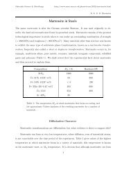
PZT- Pb(Zr x Ti 1-x )O 3<br />
One <strong>of</strong> the most widely used piezoelectrics is PZT: Zr and Ti ions occupy the perovskite B-site at<br />
random. Properties can be changed by varying x. Depending on the composition and temperature,<br />
different phases <strong>of</strong> PZT are thermodynamically stable:<br />
← Morphotropic Phase<br />
Boundary<br />
→<br />
(x = 1) (x = 0)<br />
e.g. ~50 mol.% PbTiO 3<br />
/ 50 mol.% PbZrO 3<br />
, at room temperature: the system is close to the<br />
tetragonal / rhombohedral phase boundary. Hence there are 6 possible tetragonal distortions,<br />
and 8 possible rhomobohedral distortions, along which polarisation states can form (see<br />
BH30). This means that there are a total <strong>of</strong> 14 possible orientations along which the polarisation can<br />
be directed, and hence this composition can be easy poled & switched.
BH36 Course B: <strong>Materials</strong> for Devices BH36<br />
Magnetic <strong>Materials</strong><br />
Magnetic moments are produced by spinning electrons orbiting the atomic nucleus. Some atoms /<br />
ions behave as magnetic dipoles.<br />
Electron spin +<br />
orbital angular<br />
momentum<br />
e<br />
-<br />
+<br />
The magnetisation <strong>of</strong> a material is a function <strong>of</strong> how strong the separate moments are, and how well<br />
aligned they are. The relative orientation may be influenced by neighbouring moments and by an<br />
external field. They may be randomly oriented, or perfectly aligned, or somewhere in between.<br />
For atoms with complete shells, all electron states are full (paired up, with opposite spins), so both<br />
orbital and spin angular momentum average out to zero. Hence magnetism depends upon electrons in<br />
incomplete shells (valence electrons).<br />
Magnetisation, M = magnetic moment per unit volume: i.e. A m 2 per m 3<br />
Magnetic Moment:<br />
current × area<br />
which has the same units as an applied Magnetic Field, H i.e. Am -1<br />
M = χH<br />
Susceptibility, χ (dimensionless)<br />
current,<br />
A<br />
area,<br />
m 2<br />
Diamagnetism<br />
€<br />
Orbital shells are filled, no unpaired electrons - with no external field there can be no net moment. In<br />
an applied magnetic field electron orbits react to oppose the external flux ⇒ moments develop to<br />
oppose the field ⇒ χ is negative, e.g. ~ −10 -5 (e.g. graphite, noble gases)<br />
Paramagnetism<br />
Some unpaired electrons in partially filled shells, so<br />
dipoles exist, but they’re isolated and non-interacting<br />
⇒ they are randomly oriented.<br />
With no external field the overall moment is zero.<br />
In an applied field there is partial alignment <strong>of</strong><br />
moments in the direction <strong>of</strong> the field ⇒ χ is positive,<br />
but small, e.g. ~10 -5 (e.g. many metals, Na, O 2<br />
)
BH37 Course B: <strong>Materials</strong> for Devices BH37<br />
Ferromagnetism<br />
Many unpaired electrons, i.e. partially filled shells ⇒ strong<br />
interaction between moments. Moments tend to align with<br />
each other (parallel moments have lowest energy). This is a<br />
quantum mechanical effect: the magnitude <strong>of</strong> the exchange<br />
interaction depends upon the overlap <strong>of</strong> electron wave<br />
functions, & therefore depends upon the crystal structure as<br />
well as electron spin (not simply dipole–dipole interaction).<br />
Moments align with an applied field, and orientation can<br />
become permanent, i.e. remain aligned without an external<br />
field. Parallel alignment <strong>of</strong> moments leads to a large net<br />
magnetisation, even in zero field. e.g. χ (Fe) = 5.10 3<br />
Cooperative Alignment (e.g. Fe, Ni, Co)<br />
Antiferromagnetism<br />
Strong interaction between moments, but anti-parallel<br />
moments have the lowest energy.<br />
The two sets <strong>of</strong> moments are exactly equal & opposite<br />
⇒ net magnetic moment = 0<br />
The only AF element at room temperature is Cr.<br />
More complex forms <strong>of</strong> magnetic ordering can exist in ionic<br />
compounds, and these are controlled by the crystal structure.<br />
e.g. may have two magnetic sub-lattices in which the moments<br />
align anti-parallel with each other:<br />
Ferrimagnetism<br />
As for antiferromagnetism, but the moments on the two<br />
sub-lattices are unequal ⇒ a net magnetisation.<br />
e.g. magnetite: Fe 3<br />
O 4<br />
, which has two different types <strong>of</strong><br />
Fe lattice site.
BH38 Course B: <strong>Materials</strong> for Devices BH38<br />
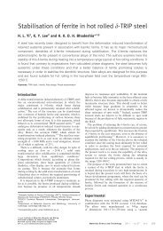
Ferromagnetic <strong>Materials</strong><br />
Magnetisation<br />
Curie Temperature, T C<br />
Thermal agitation competes with exchange<br />
interaction at high temperature.<br />
Ferromagnetic<br />
Temperature<br />
Paramagnetic<br />
χ becomes very high around T C<br />
:<br />
the magnetic moment changes<br />
rapidly at the transition.<br />
Magnetocrystalline anisotropy M<br />
Interaction <strong>of</strong> the magnetic moment with the crystal<br />
lattice means that the preferred direction <strong>of</strong> the magnetic<br />
moment is dependent upon the crystalline direction.<br />
Energy is lowest when the magnetisation points along a<br />
specific crystallographic direction.<br />
⇒ easy and hard crystallographic axes:<br />
Fe (bcc) Ni (fcc) Co (hex.)<br />
easy <br />
↓ <br />
hard <br />
easy<br />
hard<br />
Saturation magnetisation<br />
H<br />
Domain formation A ferromagnetic material is not necessarily magnetised …..<br />
Stray fields have an energy cost, which can be reduced by the formation <strong>of</strong> magnetic domains. Each<br />
domain is spontaneously magnetised, but they’re in different orientations.<br />
→ → decreasing stray field → →<br />
→ increasing domain wall energy →
BH39 Course B: <strong>Materials</strong> for Devices BH39<br />
Shape Anisotropy<br />
Magnetisation is also a function <strong>of</strong> the sample shape,<br />
e.g. lower energy for magnetisation to lie along the length<br />
<strong>of</strong> a long, thin sample (think <strong>of</strong> the stray field lines). This<br />
also applies to grains within a sample.<br />
Magnetostriction<br />
Upon magnetisation a crystal experiences a strain, and will change its dimensions. Conversely,<br />
application <strong>of</strong> a stress can lead to a change in magnetisation. Dimensional changes in differently<br />
aligned neighbouring domains lead to elastic strain energy.<br />
Magnetostriction coefficient, Λ: fractional change in length on changing magnetisation from zero to<br />
saturation. This may be +ve, or –ve. e.g. Ni: Λ = –5.10 -5 along & –2.7.10 -5 along <br />
Domain wall, or Bloch wall<br />
- transition region between two differently oriented domains<br />
e.g. for 180º wall: Wide Wall (gradual twist <strong>of</strong> moments) or Narrow Wall (abrupt change)<br />
Wall width is fixed by a balance between:<br />
Exchange Interaction Energy: This is<br />
the energy term that encourages moments<br />
to align with each other - misaligned<br />
moments have high energy.<br />
The exchange energy component is<br />
minimised by keeping misaligned spins<br />
apart (i.e. wide walls).<br />
Magnetocrystalline Energy or Anisotropy Energy:<br />
This is the energy term that encourages moments to<br />
align with the easy axis <strong>of</strong> the crystal - moments misaligned<br />
with the easy axis have high energy.<br />
The magnetocrystalline energy component is minimised<br />
by aligning spins along the preferred<br />
crystalline direction (which leads to abrupt walls).<br />
• <strong>Materials</strong> with high exchange energy & low magnetic anisotropy energy: ⇒ exchange energy<br />
term will dominate, & domain walls will tend to be wide (in order to minimise this energy term).<br />
• <strong>Materials</strong> with high magnetic anisotropy energy & low exchange energy: ⇒ anisotropy term will<br />
dominate, so energy is minimised by reducing this anisotropy energy term, i.e. having abrupt walls.<br />
Typical magnetic domain<br />
wall widths are ~5 – 100 nm<br />
Comparison with Ferroelectrics (see BH32):<br />
Anisotropy in FE crystals is very large, so it is energetically unfavourable to have a gradual change in<br />
polarisation direction at a domain wall ⇒ FE domain walls tend to be very narrow (e.g. ~1 – 10 nm).
BH40 Course B: <strong>Materials</strong> for Devices BH40<br />
Small particles:<br />
A domain structure won’t form in a small particle, or grain, if domain wall energy > stray field<br />
energy. The domain structure <strong>of</strong> a polycrystalline material depends upon grain size: grains may be<br />
too small to support a domain boundary ⇒ form uniformly magnetised, single domain grains.<br />
Ferromagnetic Hysteresis<br />
In the presence <strong>of</strong> an applied field, domains with magnetisation antiparallel to the field DO NOT<br />
spontaneously flip. It is energetically cheaper for the magnetisation to switch by moving domain<br />
walls. Plotting Magnetisation, M as a function <strong>of</strong> Applied Field, H:<br />
Extrapolation <strong>of</strong> the curve from M sat back<br />
to the axis defines the Spontaneous<br />
M<br />
a<br />
b<br />
c<br />
d<br />
dipole rotation<br />
growth <strong>of</strong> favourably<br />
Magnetisation (the net magnetisation oriented domains<br />
within a uniformly magnetised microscopic<br />
volume, in zero field) irreversible wall motion<br />
reversible wall motion<br />
H<br />
H H H H<br />
a b c d<br />
*Domains in unmagnetised<br />
sample cancel<br />
out ⇒ zero net<br />
magnetisation, M<br />
*Moments are aligned<br />
along easy axes<br />
*Wall motion and M<br />
are reversible<br />
*Favourably oriented<br />
domains grow by wall<br />
motion<br />
*M increases sharply<br />
*Wall motion is irreversible<br />
(due to pinning<br />
by imperfections)<br />
*Whole sample is<br />
aligned as a single<br />
magnetic domain<br />
(along easy axis, not<br />
along external field<br />
direction)<br />
*Moment is pulled<br />
away from easy axis,<br />
into line with external<br />
field<br />
*Saturation magnetisation<br />
M sat produced<br />
by rotation <strong>of</strong> moments<br />
to lie along H
BH41 Course B: <strong>Materials</strong> for Devices BH41<br />
Cycling the field back and forth produces hysteresis:<br />
Residual magnetisation remaining at zero<br />
applied field (H = 0) is the remanent<br />
Reduce applied field ⇒ moment relaxes back to<br />
easy crystallographic axis, but then the domain<br />
remains stable as field is reduced further<br />
magnetisation, M r<br />
magnetisation<br />
M sat<br />
Continued field reversal ⇒ domains<br />
grow in the opposite direction<br />
M = 0 (multi-domain umagnetised<br />
state) at the coercive field, H C .<br />
applied field<br />
Further field reversal ⇒<br />
saturation in the opposite<br />
direction<br />
M sat<br />
• area within the loop ∝ energy dissipated during one<br />
cycle, i.e. 2 × energy needed to switch M<br />
• imperfections (grain boundaries, impurities, vacancies, etc.) pin domain walls, ⇒ increase H C
BH42 Course B: <strong>Materials</strong> for Devices BH42<br />
Aside on magnetic parameters:<br />
If a magnetic field, H, is applied to a material, the resultant magnetic flux density, B, is<br />
B = µH = µ 0 ( H + M ) with units <strong>of</strong> Tesla, T<br />
µ = permeability <strong>of</strong> material; µ 0 = permeability <strong>of</strong> free space (4π×10 -7 H m -1 ); M = χH (BH36)<br />
( ) = µ 0<br />
H( 1+ χ) and<br />
µ = µ 0 ( 1+ χ)<br />
B = µ 0<br />
H + χH<br />
€<br />
Although B (also called the inductance) is the parameter that we measure, it is useful to consider M,<br />
the magnetisation, since it can be calculated from first principles:<br />
€ M (A m -1 ) = magnetic moment per atom (A m€<br />
2 ) × no. <strong>of</strong> atoms per unit volume (m -3 )<br />
Hysteresis loops<br />
Different shapes for different applications:<br />
M<br />
M<br />
M<br />
H<br />
H<br />
Large M r and H c for<br />
permanent magnets.<br />
High, stable magnetisation.<br />
Well defined switching field,<br />
(i.e. sharp change in magnetisation)<br />
for memory devices.<br />
High M sat and low H c<br />
for easy switching in<br />
transformer cores<br />
Best s<strong>of</strong>t magnetic materials: want very small loop area. Therefore get rid <strong>of</strong> imperfections<br />
(crystalline defects, grain boundaries, impurities, vacancies, strains, etc.) that would pin domain walls.<br />
Use long heat treatments (annealing) to form (ideally) ‘perfect’ crystal, through which domain walls<br />
sweep without hindrance. Or, use very homogeneous, amorphous materials (e.g. H C<br />
≈ 3 A m -1 ).<br />
Best hard magnetic materials: want to pin domain walls. Therefore incorporate imperfections,<br />
defects & stresses by quenching (cooling very rapidly from a high processing temperature, which<br />
doesn’t allow re-organisation). Or, by compressing fine powders (sintering) to leave many<br />
independent particles (e.g. H C<br />
≈ 1.10 6 A m -1 )..
BH43 Course B: <strong>Materials</strong> for Devices BH43<br />
Ferrimagnetism & the Spinel Structure<br />
Spinel: nearly cubic close packed oxygen ions, with two types <strong>of</strong> cation sites.<br />
2 × 2 × 2 fcc cells:<br />
e.g. MgAl 2 O 4<br />
A-site<br />
Mg 2+<br />
Mg 2+ in tetrahedral interstices<br />
Al 3+ in octahedral interstices<br />
B-site<br />
Al 3<br />
Normal Spinel<br />
1 / 8<br />
<strong>of</strong> the tetrahedral<br />
A-sites are occupied by<br />
divalent ions<br />
1 / 2<br />
<strong>of</strong> the octahedral<br />
B-sites are occupied<br />
by trivalent ions<br />
The Inverse Spinel structure e.g. Fe 3 O 4 (magnetite):<br />
Fe can be 2+ or 3+ and Fe 3 O 4 is actually Fe 2+ O.Fe 3+ 2 O 3<br />
Fe 2+ ions are on B-sites / Fe 3+ ions are divided equally between A (tetrahedral) & B (octahedral)<br />
sites,<br />
i.e. (Fe 3+ ) A (Fe 2+ Fe 3+ ) B O 2 -<br />
4<br />
Spin moments <strong>of</strong> all Fe 3+ ions on B-sites are aligned parallel to each other, but opposite to the spin<br />
moments <strong>of</strong> the Fe 3+ ions on the A-sites. Hence Fe 3+ spin moments exactly cancel.<br />
Spin moments <strong>of</strong> all Fe 2+ ions are aligned parallel to each other, giving the total moment, responsible<br />
for the net magnetisation.<br />
⇒ magnetite is Ferrimagnetic
BH44 Course B: <strong>Materials</strong> for Devices BH44<br />
Solid Ionic Conducting <strong>Materials</strong><br />
Ceramics, which are compounds between metallic and non-metallic elements (e.g. oxides, nitrides,<br />
carbides), are generally electrically insulating (all electrons are bound to atoms or bonds):<br />
e.g. Al 2<br />
O 3<br />
: resistivity, ρ = ~10 10 Ωm or conductivity, σ =10 -10 Ω −1 m −1 or Sm -1<br />
c.f. Cu: ρ = 1.6×10 -8 Ωm σ = 6×10 7 Ω −1 m −1<br />
However, some ceramics can conduct via ionic conduction.<br />
e.g. the ionic conductivity <strong>of</strong> (ZrO 2<br />
+ 8 mol.% Y 2<br />
O 3<br />
) is ~ 0.1 Ω −1 m −1 @ 500° C<br />
An example <strong>of</strong> a ceramic structure:<br />
interstitial<br />
+<br />
vacancy<br />
anion<br />
(Frenkel defect)<br />
+<br />
cation<br />
vacancies<br />
(Shottky<br />
defect) → charge neutrality<br />
Ions / atoms aren’t completely stationary on their lattice sites; the higher the temperature, the larger<br />
the amplitude with which they vibrate. They can migrate through the lattice by swapping position with<br />
other ions / atoms, and this migration is greatly enhanced by the existence <strong>of</strong> vacant sites.<br />
Ions migrate by hopping into vacant lattice sites:<br />
Ionic mobility depends upon:<br />
- whether an adjacent site is empty, and<br />
- the energy barrier between lattice sites<br />
An ionic current flow can result from:<br />
(a) a concentration gradient (<strong>of</strong> ions, or vacancies): diffusion current<br />
(random diffusion evens out the gradient) and / or<br />
(b) an electric field, E: drift current
BH45 Course B: <strong>Materials</strong> for Devices BH45<br />
Flux <strong>of</strong> atoms or ions (atomic / ionic flux), J:<br />
number <strong>of</strong> atoms or ions crossing unit area,<br />
in unit time, i.e. m -2 s -1<br />
(a) Diffusion current (due to a concentration gradient)<br />
Fick’s 1 st law <strong>of</strong> diffusion: flux, J = −D ∂n<br />
∂x<br />
D = diffusivity, or diffusion coefficient (m 2 s -1 ) n = concentration <strong>of</strong> diffusing ions (m -3 )<br />
Diffusion current density: € j = −qD ∂n (A m -2 )<br />
∂x<br />
q = z e = charge on diffusing ion<br />
(z = charge number or valence; e = electronic charge = 1.6×10 -19 C)<br />
€<br />
This applies only to steady-state diffusion in a uniform concentration gradient (in one dimension):<br />
Atoms / ions move down the concentration<br />
gradient (oppositely charged vacancies move<br />
in the opposite direction) by random diffusion.<br />
n<br />
- - - -<br />
energy<br />
lattice sites<br />
+ +<br />
+ +<br />
x<br />
distance<br />
Illustration <strong>of</strong> the energy barrier between lattice sites,<br />
Q = lattice energy barrier or activation energy<br />
(J mol -1 or, <strong>of</strong>ten, eV atom -1 ; 1 eV = 1.6×10 -19 J)<br />
Arrhenius equation:<br />
D = D 0<br />
exp −Q RT<br />
( ) or D = D exp −Q 0 ( kT )<br />
Mobility, or diffusivity, depends upon the probability<br />
that an atom / ion can exceed this energy barrier, Q.<br />
depending on units used for Q<br />
R = gas constant, 8.314 J K -1 mol -1 ; k = Boltzmann constant, 1.38×10 -23 J K -1 atom -1<br />
pre-exponential factor, D 0 , is related to the atomic vibrational frequency & lattice spacing
BH46 Course B: <strong>Materials</strong> for Devices BH46<br />
(b) Drift current (due to an electric field)<br />
energy<br />
Addition <strong>of</strong> an electric field<br />
field, E →<br />
(E, direction <strong>of</strong> positive charge flow)<br />
⇒ reduction <strong>of</strong> Q in one direction (&<br />
equivalent increase in the opposite direction)<br />
energy barrier = (Q – y)<br />
€<br />
The current density is governed by the conductivity (the ease <strong>of</strong> motion) & the electric field (the<br />
driving force), and is given by the microscopic form <strong>of</strong> Ohm’s law.<br />
If σ = conductivity:<br />
drift current density,<br />
€<br />
j = −σ ∂V<br />
∂x<br />
E = − ∂V<br />
∂x ,<br />
current flow (+ve charge)<br />
V<br />
j →<br />
from high to low potential<br />
E →<br />
and so<br />
The number € <strong>of</strong> diffusing ions in an electric potential follows Boltzmann’s statistics:<br />
Therefore<br />
€<br />
j drift<br />
= σE<br />
⎛⎛<br />
n = n o<br />
exp⎜⎜<br />
−qV ⎞⎞<br />
⎟⎟ and the differential gives the concentration gradient:<br />
⎝⎝ kT⎠⎠<br />
∂n<br />
∂x = −q ⎛⎛ ⎛⎛<br />
n 0<br />
exp −qV ⎞⎞⎞⎞<br />
⎜⎜ ⎜⎜ ⎟⎟⎟⎟ × ∂V<br />
kT ⎝⎝ ⎝⎝ kT ⎠⎠⎠⎠<br />
∂x<br />
∂n<br />
∂x = −nq ∂V<br />
kT ∂x = nqE<br />
kT<br />
Voltage,<br />
i.e. the electric field leads to a concentration gradient<br />
Distance,<br />
x<br />
At equilibrium the diffusion current density (BH45) j diffusion<br />
= − qD ∂n , due to this resultant<br />
∂x<br />
concentration gradient, must be equal to the drift current density, i.e. - j diffusion = j drift :<br />
qD ∂n<br />
∂x = σE ⇒<br />
⎛⎛<br />
qD nqE ⎞⎞<br />
⎜⎜ ⎟⎟ = σE<br />
⎝⎝ kT ⎠⎠<br />
€<br />
σ<br />
€<br />
D = nq2<br />
kT<br />
Nernst-Einstein equation<br />
€
BH47 Course B: <strong>Materials</strong> for Devices BH47<br />
since<br />
D = D o<br />
exp( −Q kT) (BH45) and<br />
⎛⎛<br />
n = n o<br />
exp⎜⎜<br />
−qV ⎞⎞<br />
⎝⎝ kT⎠⎠<br />
⎟⎟ (BH46)<br />
Nernst-Einstein (BH46): σ = Dnq2<br />
kT<br />
€<br />
Therefore,<br />
⎛⎛<br />
lnσ ≈ lnσ 0<br />
− Q ⎞⎞<br />
⎜⎜ ⎟⎟ 1 ⎝⎝ k ⎠⎠ T<br />
≈ D n o o q2<br />
exp −Q<br />
kT kT<br />
€<br />
( ) for small E, where<br />
€<br />
where σ 0<br />
= D n 0 0 q2<br />
kT<br />
qV
1 / 4<br />
, 3 / 4 1 / 4<br />
, 3 / 4<br />
BH48 Course B: <strong>Materials</strong> for Devices BH48<br />
Solid State Ionic Conductors<br />
For high levels <strong>of</strong> ionic conductivity a structure should include vacancies, or disordered regions.<br />
e.g. anion conductors<br />
yttrium stabilised zirconia (YSZ): (ZrO 2 + x mol.% Y 2 O 3 ); doped forms <strong>of</strong><br />
CeO 2 , Bi 2 O 3 (O 2- ions), and CaF 2 , PbF 2 (F - ions)<br />
cation conductors<br />
doped-Al 2 O 3 (with Na + or Ca 2+ ions), AgI (Ag + ions) – see BP4<br />
Yttrium Stabilized Zirconia, YSZ: formation <strong>of</strong> oxygen vacancies by doping<br />
Start with zirconia, ZrO 2 (fluorite structure: cations in an fcc arrangement & anions in all tetrahedral<br />
interstices – see Data Book & AH31).<br />
UN-DOPED<br />
1 / 2<br />
O 2-<br />
1 / 4<br />
, 3 / 4 1 / 4<br />
, 3 / 4<br />
Zr 4+<br />
1 / 2 1 / 2<br />
1 / 2<br />
- dope with yttria, Y 2 O 3 : Y 3+ ions substitute for Zr 4+<br />
- to maintain charge neutrality, oxygen vacancies are created:<br />
(cation substitution using different valence ions)<br />
for every 2 Zr 4+ ions replaced with 2 Y 3+ ions there is a loss <strong>of</strong> charge <strong>of</strong> 2+<br />
⇒ one oxygen vacancy is formed (with an effective charge <strong>of</strong> 2+)<br />
Oxygen ions, O 2- , are the carriers, & oxygen vacancies mediate the conduction.<br />
Pure, undoped ZrO 2 is monoclinic at room temperature. The addition <strong>of</strong> Y 2 O 3 to ZrO 2 is also<br />
beneficial because it allows the cubic form <strong>of</strong> fluorite (required for high ionic conductivity) to be<br />
stabilised over a wide temperature range (room temp. → ~2500°C).<br />
δ-Bi 2 O 3<br />
Fluorite structure, with two formula units per cell.<br />
⇒ in each unit cell:<br />
⇒<br />
8 tetrahedral oxygen sites<br />
6 oxygen ions (on average)<br />
2 oxygen vacancies per cell (on average)
BH49 Course B: <strong>Materials</strong> for Devices BH49<br />
Applications <strong>of</strong> Ionic Conductors<br />
Solid ionic conductors are analogous to electrolytic conductors, in that they can transport ions.<br />
1. Oxygen Concentration Cell<br />
anode<br />
cathode<br />
(for monitoring oxygen levels)<br />
pO 2 (I)<br />
YSZ solid<br />
electrolyte<br />
2O 2 -<br />
pO 2 (II)<br />
porous Pt electrodes (catalyse the<br />
reactions & conduct electrons)<br />
4e -<br />
If there are different O 2 concentrations (partial pressures) at each electrode, oxygen is transported<br />
from the high to the low concentration:<br />
Pt(s) | O 2 (g)(I) | YSZ | O 2 (g)(II) | Pt(s)<br />
If partial pressure <strong>of</strong> oxygen, pO 2 (I) < pO 2 (II):<br />
Half cell reactions: O 2 (g)(II) + 4e - → 2O 2- reduction (cathode)<br />
2O 2- → O 2 (g)(I) + 4e -<br />
oxidation (anode)<br />
Overall: O 2 (g)(II) → O 2 (g)(I)<br />
Ions are transported across the electrolyte / Electrons through the external circuit.<br />
Electrochemistry tells us that<br />
E = − RT<br />
4F ln pO 2(I)<br />
pO 2<br />
(II)<br />
E = electrochemical cell potential (Volts)<br />
[Note: not field in this case]<br />
F = Faraday’s constant (96,500 C mol -1 ) R = gas constant (8.314 J K -1 mol -1 )<br />
- if pO 2 (I) < pO 2 (II) E will be +ve, O 2- from (II) → (I)<br />
- if pO 2 (I) > pO 2 (II) E will be -ve, O 2- from (I) → (II)
BH50 Course B: <strong>Materials</strong> for Devices BH50<br />
Use as an O 2 sensor, e.g. for<br />
combustion control in car engines.<br />
Lambda Sensor: fitted into<br />
vehicle exhaust system to<br />
measure oxygen level, and<br />
hence adjust fuel supply to<br />
increase efficiency and<br />
decrease emissions.<br />
permeable<br />
platinum<br />
electrodes<br />
YSZ<br />
electrolyte<br />
reference gas<br />
chamber at<br />
atmosphere<br />
exhaust gas<br />
↓<br />
exhaust manifold<br />
heater<br />
protective<br />
porous<br />
ceramic<br />
heater<br />
connection<br />
voltage<br />
measurement<br />
(see BP4)<br />
The self generated voltage shows the difference in oxygen partial pressure between the exhaust and<br />
the atmosphere. The sensor is linked via a computer to the fuel injection system to allow control <strong>of</strong><br />
the air / fuel ratio. The aim is to achieve complete stoichiometric combustion <strong>of</strong> petrol in order to<br />
minimise emissions (unburned fuel, CO, NO x ):<br />
C 8 H 18 + 25<br />
2 O 2 → 8CO 2 +9H 2 O<br />
From this equation, taking account <strong>of</strong> the relative molecular masses <strong>of</strong> the components & that the<br />
atmosphere is ~4 N 2<br />
/ 1 O 2<br />
), for stoichiometric combustion the air-to-fuel-ratio (by weight) = 14.6.<br />
measured ratio<br />
Define λ = ( ) i.e. want λ = 1<br />
14.6<br />
€<br />
1.0<br />
cell potential oxygen partial pressure<br />
emf (V)<br />
emf<br />
pO 2<br />
0.5<br />
10 -1<br />
10 -11<br />
pO 2 (atm)<br />
Fuel-rich<br />
Lean-burn<br />
|<br />
0.0<br />
0.9<br />
λ=1<br />
1.1<br />
10 -21<br />
pO 2 < 10 -20 atm ← fuel-rich ← .0 → lean-burn → pO 2 > 10 -2 atm<br />
high potential ⇒ add oxygen<br />
low potential ⇒ add fuel
BH51 Course B: <strong>Materials</strong> for Devices BH51<br />
2. Oxygen Pump<br />
O 2- can be driven across a membrane using an metal / metal oxide mix<br />
applied potential. This may be used for removing<br />
oxygen from molten metals during processing.<br />
molten<br />
metal e -<br />
3. Fuel Cell - produce electricity by direct oxidation <strong>of</strong> fuel.<br />
In normal combustion (e.g. in flames, or internal combustion engines), fuels react with oxygen: the<br />
fuel donates electrons to the oxygen atoms (fuel is oxidised; oxygen is reduced).<br />
A fuel cell is an electrochemical device that converts the chemical energy in a fuel directly into<br />
electrical energy (like a battery, but with the fuel continually supplied, instead <strong>of</strong> there being a fixed<br />
source which is eventually used up). The fuel is typically CH 4 or H 2 , and the oxidation and reduction<br />
reactions are separated by an electrolyte.<br />
e.g. solid oxide fuel cell (SOFC)<br />
anode: oxidation<br />
H 2 + O 2- → H 2 O + 2e -<br />
current<br />
loop<br />
e.g. YSZ<br />
cathode: reduction<br />
O 2 + 4e - →2O 2-<br />
• high efficiency (e.g. up to ~60%; around twice that <strong>of</strong> an internal combustion engine)<br />
• no polluting emissions if C is absent in the fuel<br />
• no noise
BH52 Course B: <strong>Materials</strong> for Devices BH52<br />
For effective ion conduction, the electrolyte (typically YSZ) needs to run at ~600 – 1000°C.<br />
Need high ion conductivity & low electron conductivity.<br />
Anode: electrically conducting; porous (to fuel, & water)<br />
Cathode: electrically conducting; permeable to oxygen<br />
(must not oxidise)<br />
⇒ conducting ceramic: “cer-met”<br />
⇒ doped porous manganite<br />
stack many together, in series to give a useful voltage<br />
cross-section<br />
<strong>of</strong> real cell<br />
Using H 2 fuel<br />
anode | H 2 (g) | YSZ | O 2 (g) | cathode<br />
Using CH 4 fuel<br />
anode | CH 4 (g) | YSZ | O 2 (g) | cathode<br />
Overall cell reaction:<br />
2H 2 (g) + O 2 (g) → 2H 2 O(g)<br />
CH 4 (g) + 2O 2 (g) → CO 2 (g) + 2H 2 O(g)<br />
Half cell reactions:<br />
2H 2 (g) + 2O 2- → 2H 2 O(g) + 4e - (anode)<br />
CH 4 (g) + 4O 2- → CO 2 (g) + 2H 2 O(g) + 8e -<br />
O 2 (g) + 4e - → 2O 2-<br />
(cathode)<br />
2O 2 (g) + 8e - → 4O 2-<br />
Major materials challenges:<br />
High operating temperature – need stability; no inter-reaction, or inter-diffusion; matched thermal<br />
coefficients <strong>of</strong> expansion.<br />
Anode operates in a highly reducing environment; Cathode in an oxidising environment.
BH53 Course B: <strong>Materials</strong> for Devices BH53<br />
Fuel cell cars <strong>of</strong>ten use polymer electrolyte membrane fuel cells (PEMFC). Instead <strong>of</strong> YSZ, these<br />
use thin, flexible polymer membranes (operating at ~80°C), which conduct protons (H + ). The overall<br />
reaction is the same, but the half cell reactions are different, since H + , rather than O 2- , is transported<br />
through the electrolyte:<br />
Overall cell reaction: 2H 2 (g) + O 2 (g) → 2H 2 O(g)<br />
Half cell reactions: 2H 2 (g) → 4H + (g) + 4e - (anode) transport <strong>of</strong> protons<br />
across membrane,<br />
rather than oxygen<br />
O 2 (g) + 4H + + 4e - → 2H 2 O(g) (cathode) ions across electrolyte<br />
sulphonated fluoropolymer membrane:<br />
There’s a great advantage in the lower running temperature, but currently these require expensive Ptbased<br />
catalysts.<br />
The Hydrogen Economy<br />
This requires hydrogen storage by compressing or liquefying the gas, which is energy intensive. It’s<br />
also extremely flammable! Alternatively, we can produce H 2 where it’s required, by electrolysing<br />
water:<br />
H 2 O(l) → H 2 (g) + 1 / 2 O 2 (g) which requires energy input<br />
or, by separating H from C in hydrocarbons (reforming): pass fuel & H 2 O over a heated catalyst<br />
→ CO / CO 2 & H 2 (still polluting, & relies on fossil fuels)
BH54 Course B: <strong>Materials</strong> for Devices BH54<br />
Glossary <strong>of</strong> Terms<br />
Activation energy, Q: in diffusion, this is related to the energy required to move an atom from one<br />
lattice site to another (J mol -1 , or eV atom -1 )<br />
Anode: the electrode at which oxidation occurs.<br />
Anisotropic: having different properties in different directions.<br />
Antiferromagnetism: opposition <strong>of</strong> adjacent magnetic dipoles causing zero net magnetisation.<br />
Arrhenius plot: plot <strong>of</strong> ln(rate) for a process or reaction, versus 1/T. The slope is proportional to<br />
the activation energy.<br />
Atactic polymer: a polymer with configurational base units in a random sequence.<br />
Backbone: the main structure <strong>of</strong> a polymer onto which substituents are attached.<br />
Birefringence, Δn: the difference in refractive index between two permitted vibration directions.<br />
Bloch walls: the boundaries between magnetic domains.<br />
Capacitance, C: charge per unit voltage (Farads, or C V -1 )<br />
Capacitor: electrical device consisting <strong>of</strong> alternating layers <strong>of</strong> dielectric and conductor, which is<br />
capable <strong>of</strong> storing charge.<br />
Cathode: the electrode at which reduction occurs.<br />
Centre <strong>of</strong> symmetry: a point through which an object can be inverted (i.e. all x, y, z are transformed<br />
to –x, -y, -z) to bring the object into coincidence with itself.<br />
Centrosymmetric: possessing a centre <strong>of</strong> symmetry.<br />
Ceramics: compounds <strong>of</strong> metallic anions with non-metallic cations, which commonly have very<br />
high melting temperatures<br />
Chiral nematic, or Cholesteric: molecules in adjacent layers are oriented at a slight angle relative<br />
to each other (rather than parallel, as in the nematic). Therefore the Director rotates helically, around<br />
an axis perpendicular to the layers.<br />
Compensator: sample <strong>of</strong> an optically anisotropic crystal with a known birefringence (<strong>of</strong>ten quartz).<br />
Coercive field, E C<br />
/ H C<br />
: the electric / magnetic field that is required to depolarise / demagnetise a<br />
ferroelectric / magnetic material (V m -1 / A m -1 )<br />
Concentration cell: an electrochemical cell whose electromotive force is driven by differences in<br />
concentrations across the electrolyte.<br />
Concentration gradient: the rate <strong>of</strong> change <strong>of</strong> composition with distance (m -4 ).<br />
Conformation: the structure <strong>of</strong> a polymer chain that arises from rotation about the single bonds.<br />
Constructive interference: the combination <strong>of</strong> rays which are in phase and give an intense beam.<br />
Coordination number: the number <strong>of</strong> atoms forming a polyhedron around a central atom in a<br />
structure.<br />
Coordination polyhedron: the polyhedron that can be constructed around a cation with the<br />
surrounding anions forming the vertices.
BH55 Course B: <strong>Materials</strong> for Devices BH55<br />
Cross-linking: a process in which bonds are formed joining adjacent molecules. At low density<br />
these bonds add to the elasticity <strong>of</strong> a polymer, at higher densities they produce rigidity.<br />
Crossed polars: two sheets <strong>of</strong> polarizing material (polarizer and analyzer), oriented at 90° to each<br />
other, between which a sample is placed for optical examination.<br />
Curie temperature: the temperature above which ferroelectric / ferromagnetic behaviour is lost<br />
(°C or K).<br />
Current density, j: the current flowing through unit cross-sectional area (A m -2 ).<br />
Diamagnetism: the effect caused by the magnetic moment due to orbiting electrons which produces<br />
a slight opposition to imposed magnetic field.<br />
Dielectric: an electrical insulator which is polarisable.<br />
Dielectric breakdown: the passage <strong>of</strong> current through a dielectric material upon application <strong>of</strong> a<br />
large electric field. The maximum field that a dielectric can sustain without breakdown is the<br />
dielectric strength.<br />
Dielectric constant, κ : a measure <strong>of</strong> the rate <strong>of</strong> change <strong>of</strong> polarisation with electric field; the ratio<br />
<strong>of</strong> the permittivity <strong>of</strong> a material to the permittivity <strong>of</strong> free space.<br />
Diffusion: transport <strong>of</strong> atoms in which the diffusing atom moves relative to its neighbours.<br />
Diffusion coefficient (or diffusivity), D: a temperature dependent coefficient related to the rate at<br />
which atoms diffuse, which also depends on the activation energy (m 2 s -1 )<br />
Dipole: two equal charges <strong>of</strong> opposite sign, separated by a small distance.<br />
Dipole moment, µ: the electric field generated by a spatial separation <strong>of</strong> positive and negative<br />
charges (C m) or the magnetic moment generated by electron orbitals and spin.<br />
Director, D: the direction <strong>of</strong> preferred orientation <strong>of</strong> molecules in liquid crystals.<br />
Disclination: point at which the Director in a liquid crystal undergoes an abrupt change in<br />
orientation.<br />
Displacement field, D: resultant total polarisation field created in a material by application <strong>of</strong> an<br />
electric field (C m -2 )<br />
Domains: regions within a material in which all the electric / magnetic dipoles are aligned.<br />
Domain wall: the boundary between ferroelectric / magnetic domains.<br />
Drift velocity: the average rate at which charge carriers move through a material under the<br />
application <strong>of</strong> an electric field (m s -1 )<br />
Exchange interaction / exchange energy: a quantum mechanical electron – electron interaction<br />
which favours parallel alignment <strong>of</strong> magnetic moments. A negative exchange interaction favours antiparallel<br />
alignment <strong>of</strong> moments.<br />
Extinction positions: orientations in which an anisotropic material appears black between crossed<br />
polars. (They occur every 90°, when the permitted vibration directions <strong>of</strong> the sample are parallel<br />
to the polarizer / analyzer.)<br />
Fatigue: accumulation <strong>of</strong> defects in a ferroelectric material which gradually degrades the amount <strong>of</strong><br />
switched charge.
BH56 Course B: <strong>Materials</strong> for Devices BH56<br />
Ferrimagnetism: magnetic behaviour obtained when two types <strong>of</strong> dipole, with different strengths,<br />
oppose one another, leaving a net magnetization.<br />
Ferroelectric: a material possessing a spontaneous net electrical polarisation which can be switched<br />
by an external electric field. A ferroelectric material must be polar (and switchable).<br />
Ferroelectric phase transition: transition from a high temperature paraelectric phase to a low<br />
temperature ferroelectric phase. Characterised by onset <strong>of</strong> spontaneous polarisation.<br />
Ferroelectric / magnetic hysteresis: difference in polarisation / magnetisation behaviour upon<br />
reversing electric / magnetic field.<br />
Ferromagnetism: the existence <strong>of</strong> a spontaneous magnetic dipole; alignment <strong>of</strong> magnetic domains<br />
can result in a net magnetisation after removal <strong>of</strong> an imposed magnetic field.<br />
Flux density, J: the number <strong>of</strong> atoms / ions crossing a unit cross sectional area in unit time (m -2 s -1 ).<br />
Freedericksz Transition: reorientation <strong>of</strong> liquid crystal molecules on the application <strong>of</strong> an electric<br />
field.<br />
Frenkel defect: a crystalline defect consisting <strong>of</strong> an interstitial and a vacancy.<br />
Fuel cell: an energy conversion device that produces electricity by the electrochemical oxidation <strong>of</strong> a<br />
fuel.<br />
Hard magnet: a ferromagnetic material that has a wide hysteresis loop and high remanence.<br />
Hysteresis loop: the loop traced out by polarisation / magnetisation as an applied electric / magnetic<br />
field is cycled.<br />
Inversion centre: same as centre <strong>of</strong> symmetry.<br />
Isotactic polymer: a polymer with configurational base units in a single sequential arrangement.<br />
Isotropic: having uniform physical properties in all directions.<br />
Kuhn length / segment: a theoretical treatment <strong>of</strong> a polymer chain, divided into n Kuhn segments,<br />
with Kuhn length, l, so that each segment can be thought <strong>of</strong> as freely jointed. Complex polymers may<br />
be simply modeled as a random walk.<br />
Lambda: the air / fuel weight ratio for a petrol engine normalised by the corresponding ratio for<br />
complete stoichiometric combustion <strong>of</strong> petrol.<br />
Liquid Crystal: a phase characterised by anisotropy <strong>of</strong> properties without the existence <strong>of</strong> a 3-<br />
dimensional crystal lattice, i.e. orientational order, without positional order.<br />
Magnetic Flux Density, or Inductance, B: total magnetic flux per unit area (Tesla)<br />
Magnetic moment, m: strength <strong>of</strong> the magnetic field associated with electron orbitals / spin (A m 2 ).<br />
Magnetic permeability, µ: the ratio between magnetic flux density, B, & applied magnetic field, H<br />
(H m -1 ).<br />
Magnetic susceptibility, χ : a measure <strong>of</strong> the effect <strong>of</strong> a magnetic field on the magnetisation <strong>of</strong> a<br />
material; the ratio between magnetisation, M, and the applied field, H (dimensionless).<br />
Magnetisation, M: the sum <strong>of</strong> all magnetic moments per unit volume (A m -1 ).<br />
Magnetocrystalline anisotropy energy, K: extra energy, per unit volume, required to magnetise a<br />
material along the ‘hard’ crystallographic axis (J m -3 ).
BH57 Course B: <strong>Materials</strong> for Devices BH57<br />
Magnetostriction coefficient, Λ : fractional change in length on changing magnetisation from zero<br />
to saturation (dimensionless).<br />
Monomer: the simple chemical unit which, when many are joined together, form a polymer.<br />
Nematic: spontaneously anisotropic liquid, composed <strong>of</strong> rod-shaped molecules with parallel<br />
alignment.<br />
Optic Axis: for a birefringent sample, a direction along which no birefringence is observed, i.e. a<br />
direction perpendicular to an isotropic section. The optic axis <strong>of</strong> a nematic liquid crystal is along<br />
the Director.<br />
Optical Path Difference: the extra distance traveled by the fast ray outside an anisotropic material<br />
in the time it takes for the slow ray to reach the edge <strong>of</strong> the sample (m).<br />
Order parameter: describes the orientational order <strong>of</strong> a liquid crystalline material, taking account <strong>of</strong><br />
the deviation <strong>of</strong> orientation <strong>of</strong> individual molecules from the Director (zero for complete disorder;<br />
unity for perfect order).<br />
Paramagnetism: the net magnetic moment caused by alignment <strong>of</strong> the electron spins when a<br />
magnetic field is applied.<br />
Permitted Vibration Directions: two perpendicular directions in an anisotropic material along<br />
which the transverse electric field <strong>of</strong> light can vibrate.<br />
Permittivity, ε : describes how an electric field is affected by a dielectric (F m -1 ).<br />
Perovskite: family <strong>of</strong> ABX 3<br />
compounds which commonly show displacive phase transitions by<br />
octahedral tilts or atomic displacements.<br />
Phase: a part <strong>of</strong> a system, homogeneous in composition and structure.<br />
Phase diagram: a diagram showing the equilibrium phases and phase compositions at each<br />
combination <strong>of</strong> temperature (and/or pressure) and overall composition.<br />
Photoelasticity: stress-induced birefringence. In a polymer, this is caused by stress-induced<br />
alignment <strong>of</strong> polymer chains.<br />
Piezoelectricity: the application <strong>of</strong> stress produces a change in the dielectric polarisation <strong>of</strong> a<br />
material or, conversely, application <strong>of</strong> an electric field results in strain. Piezoelectric materials must be<br />
non-centrosymmetric.<br />
Piezoelectric coefficient, d: measure <strong>of</strong> the rate <strong>of</strong> change <strong>of</strong> dielectric polarisation with applied<br />
stress (C N -1 ).<br />
Pitch: the distance it takes for the Director in a cholesteric / chiral nematic liquid crystal to go<br />
through one complete 360° rotation (m).<br />
Polar material: a material with crystal symmetry such that it contains one (or more) unique<br />
direction.<br />
Polarization, P: the dipole moment per unit volume in a medium, or charge per unit area (C m -2 )<br />
Polarization (<strong>of</strong> light): the property <strong>of</strong> electromagnetic waves that describes the direction <strong>of</strong> the<br />
transverse electric field.<br />
Polarized light: light that has passed through a sheet <strong>of</strong> polarizer, and has a transverse electric field<br />
that vibrates in one direction only.
BH58 Course B: <strong>Materials</strong> for Devices BH58<br />
Poled ferroelectric: a ferroelectric material that has been brought to saturation by a strong electric<br />
field and then allowed to relax back to the remanent condition.<br />
Polymer: a long chain <strong>of</strong> covalently bonded atoms.<br />
Pyroelectricity: change in electrical polarisation due to a change in temperature. Pyroelectric<br />
materials must be polar.<br />
Pyroelectric coefficient, p: measure <strong>of</strong> the rate <strong>of</strong> change <strong>of</strong> dielectric polarisation with temperature<br />
(C m -2 K -1 ).<br />
Refractive Index, n: a property that describes the speed <strong>of</strong> light in a material relative to that in a<br />
vacuum. The higher the refractive index, the slower the light travels.<br />
Remanence: the polarisation / magnetisation that remains in a material after it has been removed<br />
from an applied electric / magnetic field, due to permanent alignment <strong>of</strong> dipoles (C m -2 / A m -1 ).<br />
Saturation polarisation / magnetisation: the state in which all electric / magnetic dipoles have<br />
been aligned by an applied electric / magnetic field, producing maximum polarisation / magnetisation<br />
(C m -2 / A m -1 ).<br />
Sawyer-Tower circuit: test circuit for measuring the hysteresis loop <strong>of</strong> ferroelectric materials.<br />
Schottky defect: an anion and cation vacancy pair.<br />
Smectic: liquid crystal phase in which the molecules organise themselves into layers.<br />
SOFC: Solid Oxide Fuel Cell.<br />
S<strong>of</strong>t magnet: ferromagnetic material that has a narrow hysteresis loop and little energy loss on<br />
cycling the field.<br />
Spontaneous polarisation / magnetisation: the co-operative phenomenon <strong>of</strong> electric / magnetic<br />
dipole ordering below the Curie temperature (C m -2 / A m -1 ).<br />
Stoichiometric: obeying a strict chemical formula, e.g. anion / cation ratio.<br />
Susceptibility: see Magnetic susceptibility.<br />
Syndiotactic polymer: a polymer with configurational base units in a regular, alternating sequence.<br />
Tacticity: the arrangement <strong>of</strong> side-groups on a polymer backbone.<br />
Transducer: a device that receives one type <strong>of</strong> input (such as strain) and provides a different type <strong>of</strong><br />
output (such as an electrical signal).<br />
Transformation (or transition): these terms are used interchangeably to denote a change in phase.<br />
Twisted nematic: liquid crystals physically forced to adopt a chiral structure.<br />
Unique Direction: a lattice vector in a crystal which is not repeated by any <strong>of</strong> the symmetry<br />
elements present.
Qu. Sheet 5 MATERIALS SCIENCE BQ1<br />
Course B: <strong>Materials</strong> for Devices<br />
Question Sheet 5<br />
1. A nematic liquid crystal sample, which includes various different director orientation patterns<br />
in different regions [as illustrated in the diagrams (a) – (e)], is viewed between crossed polars.<br />
The appearance <strong>of</strong> the region <strong>of</strong> the sample shown in pattern (a) is illustrated. Sketch what<br />
patterns you would observe for the other examples, if the polarizer / analyzer remain in the<br />
same orientation as for (a).<br />
(a) Orientation <strong>of</strong> liquid crystal<br />
molecules:<br />
Analyzer<br />
Appearance:<br />
Polarizer<br />
(b) (c) (d) (e)<br />
2. For this question you will need to work on-line. Access the following URL*:<br />
http://plc.cwru.edu/tutorial/enhanced/lab/lab.htm<br />
Select Colors from Birefringence on the left hand menu, read through Introduction and<br />
Instructions, and then open the Experiment page. You should see a Virtual Laboratory,<br />
<strong>of</strong>fering you control <strong>of</strong> Sample Parameters: Angle, thickness (called Length) and birefringence<br />
(called Delta n). White light is shown split into 3 components, each passing<br />
through the sample, and adding together at the right hand side to show a colour on a screen.<br />
Set the Sample Material as General, the Angle = 45 Degrees (or as close as you can get to it),<br />
and Length (i.e. sample thickness) to be about 1000 nm (the precise value is unimportant).<br />
Now vary Delta n (Δn, or birefringence), and observe what happens.<br />
Record the smallest (non-zero) values <strong>of</strong> Δn that yield zero transmission for each <strong>of</strong> blue,<br />
green and red light, and thus deduce each <strong>of</strong> their wavelengths. Note the transmitted colour<br />
when each component is completely blocked.<br />
Can you achieve zero blue transmission at a higher value <strong>of</strong> Δn<br />
Relate your results to the Michel-Levy chart printed in your <strong>handout</strong> (BH10).<br />
Why does this exercise work best with the Angle set to 45° Observe what happens as you<br />
change this value.<br />
*Courtesy <strong>of</strong> the PLC Tutorial (http://plc.cwru.edu), Macromolecular <strong>Science</strong> and Physics<br />
<strong>Department</strong>s, CWRU, and the ALCOM S&T Center<br />
MT13
BQ1 - 2 - Question Sheet 5<br />
3. A wedge <strong>of</strong> quartz, with a birefringence <strong>of</strong> 0.009 and an angle <strong>of</strong> 1°, is cut with a permitted<br />
vibration direction along its length. Describe and explain what you will see when the wedge<br />
is viewed between crossed polars, with its length at 45° to the polarizer / analyzer, in sodium<br />
light (λ = 590 nm). What is the distance between dark bands Describe and explain what<br />
happens if the wedge is then rotated so that its length lies parallel with (a) the polarizer, and<br />
(b) the analyzer.<br />
The quartz wedge is now viewed in white light, and a uniform nematic liquid crystal sample<br />
is added to the light path (i.e. the quartz wedge is placed on top <strong>of</strong> the liquid crystal sample<br />
and viewed between crossed polars). The long axes <strong>of</strong> the liquid crystal molecules in this<br />
sample (known to correspond to the slow vibration direction <strong>of</strong> the sample) are oriented<br />
parallel to the length <strong>of</strong> the wedge. A black band is observed on the wedge, 13.6 mm from its<br />
tip. Does the length <strong>of</strong> the wedge correspond to the fast or the slow vibration direction in the<br />
quartz What colour would the liquid crystal sample show if the wedge were removed<br />
The liquid crystal sample is measured to have a thickness <strong>of</strong> 0.05 mm. What is its<br />
birefringence<br />
4. A cholesteric, or twisted nematic, liquid crystal can selectively reflect light <strong>of</strong> a specific<br />
wavelength, related to its pitch (due to constructive interference <strong>of</strong> light reflecting from<br />
parallel equivalent planes). What colour light will be<br />
reflected from a twisted nematic <strong>of</strong> pitch 792 nm illuminated<br />
and viewed at 45° (see diagram).<br />
(For a hint on the geometry for constructive interference,<br />
refer to AH76.)<br />
On increasing the temperature <strong>of</strong> this sample, the<br />
reflected light becomes blue. Explain this observation.<br />
Pitch<br />
5. (a) Given that the C-C bond length is 0.154 nm and the C-H bond length is 0.114 nm, estimate<br />
the length and width <strong>of</strong> a linear polyethylene molecule consisting <strong>of</strong> 1000 carbon atoms (the<br />
tetrahedral bond angle is 109.5°).<br />
(b)<br />
(c)<br />
(d)<br />
(e)<br />
What is the molecular weight <strong>of</strong> this molecule<br />
What is the root mean squared end to end distance, assuming a completely flexible chain,<br />
made up <strong>of</strong> C-C segments which can twist and rotate completely independently<br />
What is the root mean squared end to end distance using the (more reasonable) assumption<br />
that the Kuhn length is 3.5 × one C-C segment<br />
If this chain were scaled up to the dimensions <strong>of</strong> a piece <strong>of</strong> string (e.g. about 2 mm wide),<br />
how long would it be In a scaled-up polymer model, if this piece <strong>of</strong> string represents a<br />
linear polyethylene molecule, what would be the average end to end distance in the model<br />
MT13
Qu. Sheet 6 MATERIALS SCIENCE BQ2<br />
Course B: <strong>Materials</strong> for Devices<br />
Question Sheet 6<br />
1. What is the capacitance <strong>of</strong> an empty parallel plate capacitor with plates, each with a<br />
surface area <strong>of</strong> 500 mm 2 , separated by a 2.5 mm gap What is the magnitude <strong>of</strong> the<br />
charge stored on each plate, and hence the surface charge density, if a potential<br />
difference <strong>of</strong> 10 V is applied across them<br />
If SiO 2 (κ = 4.52) is introduced between the plates (and a potential difference <strong>of</strong> 10 V<br />
is applied), calculate the capacitance, the magnitude <strong>of</strong> the charge stored on each plate<br />
and the total surface charge density on the plates. What is the polarisation <strong>of</strong> the SiO 2 <br />
With reference to the 1 st part <strong>of</strong> this question (i.e. the empty parallel plate capacitor),<br />
explain why the total charge density on the plates is not the same as the polarisation<br />
<strong>of</strong> the dielectric.<br />
What would be the surface area <strong>of</strong> a new capacitor <strong>of</strong> the same capacitance and<br />
thickness as the SiO 2 one, but made from a ferroelectric material with a dielectric<br />
constant one hundred times greater than SiO 2 <br />
2. (a) Sketch a plan, on (001), <strong>of</strong> one unit cell <strong>of</strong> the cubic ZnS sphalerite structure<br />
(putting a sulphur ion at the origin <strong>of</strong> the cell). Describe the shape <strong>of</strong> the coordination<br />
polyhedra <strong>of</strong> S around Zn. Are these filled polyhedra all in the same orientation Do<br />
they share corners, edges, or faces<br />
(b) Describe the asymmetry along the directions. Is [111] a unique direction<br />
Does sphalerite have any centres <strong>of</strong> symmetry<br />
(c) The unit cell that you have drawn is now subject to the shear stress pictured below<br />
(equivalent to a tensile stress along [ 110] and ⎡⎡<br />
⎣⎣110⎤⎤<br />
⎦⎦, and a compressive stress along<br />
⎡⎡110 ⎣⎣<br />
⎤⎤<br />
⎦⎦ and ⎡⎡<br />
⎣⎣110⎤⎤<br />
⎦⎦). Sketch a plan, on (001), <strong>of</strong> one (filled) coordination polyhedron,<br />
before and after application <strong>of</strong> the stress, and describe how the ion positions have<br />
changed. Do the centre-<strong>of</strong>-mass coordinates for the S coordination polyhedron<br />
change What about its centre-<strong>of</strong>-charge<br />
τ<br />
τ<br />
y<br />
x<br />
(d) If the Zn remains equidistant from its four coordinating sulphur ions, in what<br />
direction does it move Is it still at the centre-<strong>of</strong>-charge <strong>of</strong> the S polyhedron In what<br />
direction is the resultant dipole moment Is this the same direction for all filled<br />
polyhedra What property does this lead to<br />
τ<br />
τ<br />
MT13
Qu. Sheet 6 MATERIALS SCIENCE BQ2<br />
Course B: <strong>Materials</strong> for Devices<br />
3. A ceramic material has a piezoelectric coefficient <strong>of</strong> 250 pC N -1 and a dielectric<br />
constant <strong>of</strong> 500. A compressive stress <strong>of</strong> 5 MPa is applied across a 1 cm thick sample <strong>of</strong><br />
the material. Calculate the voltage that will develop across the sample and determine<br />
whether this is sufficient to create a spark across a 1 mm air gap. [Breakdown voltage <strong>of</strong><br />
air is ~ 3 MV m -1 ]<br />
4. Pyroelectric infra-red detectors sense temperature change through a change in surface<br />
charge on a sheet <strong>of</strong> a pyroelectric crystal, and hence a change in measured voltage<br />
across the sheet. Write down an equation for the sensitivity <strong>of</strong> the detector (ΔV/ΔT) in<br />
terms <strong>of</strong> the pyroelectric coefficient, p, and the dielectric constant, κ. Hence explain<br />
briefly why BaTiO 3 is not an ideal material to be used in a pyroelectric detector. Using<br />
information provided in the databook, estimate the ΔV/ΔT response achieved from a<br />
polyvinylidene fluoride (PVDF) detector <strong>of</strong> 1 mm thickness. Comment on the value<br />
obtained.<br />
MT13
Qu. Sheet 7 MATERIALS SCIENCE BQ3<br />
Course B: <strong>Materials</strong> for Devices<br />
Question Sheet 7<br />
1. (a) Draw a plan <strong>of</strong> the perovskite BaTiO 3<br />
structure projected onto (010), i.e. the x-z plane.<br />
Indicate mirror planes normal to the paper, and rotation axes parallel to [010]. What are the<br />
fractional coordinates <strong>of</strong> the mirror planes parallel to (010) What is the crystal system Is<br />
there a centre <strong>of</strong> symmetry and, if so, where What is the shape <strong>of</strong> the coordination<br />
polyhedra around Ti, and how are they linked<br />
(b) Re-draw the crystal structure with all the Ti cations displaced slightly along [001],<br />
towards the neighbouring oxygen (illustrate a displacement <strong>of</strong> about 1 / 5 th <strong>of</strong> the cell<br />
parameter). Which symmetry elements are lost, and which survive What is the new crystal<br />
system Is there now a centre <strong>of</strong> symmetry<br />
(c) If the Ti 4+ cation moves 0.2 Å along [001] with respect to other ions as a result <strong>of</strong> the<br />
ferroelectric phase transition in BaTiO 3<br />
, what will be the dipole moment formed in a single<br />
unit cell (Note that this displacement is much less than that depicted in (b).) If the unit cell<br />
parameter <strong>of</strong> the cubic phase is 4.0 Å, and the volume <strong>of</strong> the tetragonal phase is almost the<br />
same as that <strong>of</strong> the cubic phase, what is the polarisation If the polarisation can be thought<br />
<strong>of</strong> as an effective charge density accumulating on either side <strong>of</strong> the sample, what is the<br />
potential difference across a sample <strong>of</strong> BaTiO 3<br />
<strong>of</strong> thickness 0.1 mm and <strong>of</strong> dielectric<br />
constant 1000<br />
2. By referring to the phase diagram <strong>of</strong> PZT in your Handout (BH35), answer the following:<br />
(a) What is the Curie temperature <strong>of</strong> PbTi 0.4<br />
Zr 0.6<br />
O 3<br />
<br />
(b) What is the crystal structure <strong>of</strong> PbTi 0.6<br />
Zr 0.4<br />
O 3<br />
at room temperature<br />
(c) What conditions <strong>of</strong> polarisation would result in a specimen <strong>of</strong> PbTi 0.6<br />
Zr 0.4<br />
O 3<br />
after each<br />
<strong>of</strong> the following treatments:<br />
(i) Strong electric field applied at 750 K, held for some hours, & switched <strong>of</strong>f.<br />
Specimen cooled to 300 K.<br />
(ii) Strong electric field applied at 620 K, held for some hours, specimen cooled to<br />
300K, then field switched <strong>of</strong>f.<br />
3. The Bloch wall energy for Ni is about 10 -3 J m -2 . If a spherical Ni particle consists <strong>of</strong> two<br />
equal and opposite magnetic domains, write down an equation for the total domain wall<br />
energy <strong>of</strong> the particle, in terms <strong>of</strong> its radius, r.<br />
The stray field energy (given in Joules) <strong>of</strong> a small, single domain Ni particle <strong>of</strong> radius, r, is<br />
approximately 2×10 5 r 3 . Estimate the critical size <strong>of</strong> a Ni particle, below which magnetic domains<br />
will not form, stating your assumptions.<br />
MT13
BQ3 - 2 - Question Sheet 7<br />
4. A cubic transformer core is made from Supermalloy, and its power dissipation is found to<br />
be ~2 W at 50 Hz. What is the energy required to switch the magnetisation direction <strong>of</strong> the<br />
transformer core<br />
[Hint: a power dissipation <strong>of</strong> 2 W means 2 J s -1 , and there are 50 complete switching cycles<br />
– plus, to minus, and back again – each second.]<br />
By comparing the hysteresis loops shown in the DoITPoMS TLP Ferromagnetic <strong>Materials</strong>,<br />
estimate the energy required to switch the magnetisation direction <strong>of</strong> a similar sized piece <strong>of</strong> the<br />
hard magnet, Alcomax II.<br />
[Hint: you can make a direct comparison <strong>of</strong> hysteresis loop areas without worrying about the<br />
units used, as long as they’re the same!]<br />
5. (a) Using the data given in the table below, calculate the saturation magnetisation <strong>of</strong> elemental<br />
Fe (α).<br />
(b) Magnetite, Fe 3<br />
O 4<br />
, has the inverse spinel structure, with half <strong>of</strong> the Fe 3+ ions in octahedral sites<br />
(with spin moments aligned parallel to each other), and the other half in tetrahedral sites (again,<br />
with spin moments parallel to each other, but anti-parallel to those in the octahedral sites). Fe 2+<br />
ions are in octahedral sites, with aligned spin moments. Each cubic unit cell (a = 8.39 Å) contains<br />
8 Fe 2+ ions and 16 Fe 3+ ions. Calculate the saturation magnetisation <strong>of</strong> magnetite.<br />
Net magnetic moment (×10 -23 A m 2 )<br />
Fe atom 2.06<br />
Fe 2+ cation 3.71<br />
Fe 3+ cation 4.64<br />
MT13
Qu.Sheet 8 MATERIALS SCIENCE BQ4<br />
Course B: <strong>Materials</strong> for Devices<br />
Question Sheet 8<br />
1. (a) Sketch a unit cell <strong>of</strong> CaF 2 viewed down [001].<br />
(b) Describe the coordination <strong>of</strong> Ca by F, and <strong>of</strong> F by Ca.<br />
(c) Comment on the packing <strong>of</strong> Ca ions and the location <strong>of</strong> the F ions. How does this<br />
compare with the zinc blende structure<br />
(d) In δ-Bi 2 O 3 , the Bi sub-lattice is the same as that <strong>of</strong> Ca in CaF 2 and S in ZnS, but the<br />
stoichiometry means that there are vacant anion sites, randomly distributed. Sketch a<br />
possible unit cell <strong>of</strong> δ-Bi 2 O 3 .<br />
(e) Comment on why δ-Bi 2 O 3 is a fast ionic conductor whilst stoichiometric CaF 2 and ZnS<br />
are not.<br />
(f) Calculate the composition <strong>of</strong> YSZ (i.e. Y 2 O 3 doped ZrO 2 , Zr 1-x Y x O [2-(x/2)] ) which would<br />
give just one quarter <strong>of</strong> the oxygen vacancy concentration as in δ-Bi 2 O 3 .<br />
2. (Tripos Question; 2008)<br />
How is a high-temperature cubic zirconia phase stabilised at room temperature and what<br />
are the consequences for its oxygen mobility Describe how such a material might be<br />
used in a hydrogen fuel cell. In your answer refer to the chemical reactions involved and<br />
explain how a voltage is generated. [40%]<br />
Different amounts <strong>of</strong> yttria (Y 2 O 3 ) are added to zirconia (ZrO 2 ) to produce two ceramic<br />
materials: Y 0.1 Zr 0.9 O x and Y 0.15 Zr 0.85 O y . The molar cation compositions are readily<br />
determined, but what are the molar oxygen compositions x and y [10%]<br />
Both ceramic materials are cubic and give an X-ray diffraction pattern characteristic <strong>of</strong><br />
the fluorite structure, in which the first and largest peak is a reflection from the {111}<br />
planes. Using CuKα radiation this peak occurs at 2θ = 30.147° for Y 0.1 Zr 0.9 O x whereas it<br />
is shifted to 2θ = 29.732° for Y 0.15 Zr 0.85 O y . Give a reason for this change in the<br />
diffraction pattern between the two materials. [15%]<br />
(i) What are the oxygen vacancy concentrations, n, in Y 0.1 Zr 0.9 O x and in Y 0.15 Zr 0.85 O y <br />
(ii) At 1000°C the ionic conductivity <strong>of</strong> Y 0.1 Zr 0.9 O x is 2.5 × 10 -4 Ω -1 m -1 . What is the<br />
ionic conductivity <strong>of</strong> Y 0.15 Zr 0.85 O y at the same temperature<br />
(iii) Determine the diffusivity <strong>of</strong> oxygen in Y 0.15 Zr 0.85 O y at 1000°C. [35%]<br />
[ionic radii: Y 3+ = 1.159 Å, Zr 4+ = 0.98 Å, O 2- = 1.28 Å]<br />
3. (a) From the Arrhenius plot in your <strong>handout</strong> (BH47), showing ionic conductivity versus<br />
inverse temperature for a number <strong>of</strong> ionic conductors, estimate the activation energy for<br />
ion transport in yttria-stabilised zirconia (YSZ).<br />
(b) In Zr 0.8 Y 0.2 O 1.9 how many oxygen vacancies are there per unit cell If the lattice<br />
parameter <strong>of</strong> (cubic) YSZ is 0.54 nm, calculate the number density <strong>of</strong> vacancies.<br />
MT13
Qu.Sheet 8 MATERIALS SCIENCE BQ4<br />
Course B: <strong>Materials</strong> for Devices<br />
(c) The Nernst-Einstein equation indicates that the ratio σ /D for a given material varies<br />
only with temperature. Calculate σ/D for Zr 0.8 Y 0.2 O 1.9 at 800°C.<br />
(d) It is <strong>of</strong>ten found that the experimental values differ from those predicted by the Nernst-<br />
Einstein equation. Suggest why this might be the case.<br />
4. The α phase <strong>of</strong> silver iodide (AgI) has a cubic I lattice with a = 5.0855 Å. It is a Ag +<br />
ionic conductor at 150ºC with a diffusivity <strong>of</strong> 4.5 × 10 -11 m 2 s -1 . A potential difference is<br />
applied across a sample <strong>of</strong> AgI, using Ag for both electrodes, and current is allowed to<br />
flow:<br />
e - ↑<br />
Ag + is reduced to Ag at the cathode: Ag + + e → Ag<br />
Ag is oxidised to Ag + at the anode: Ag → Ag + + e<br />
What is the number density <strong>of</strong> charge carriers in AgI<br />
What is the conductivity <strong>of</strong> the AgI at 150°C<br />
AgI<br />
anode cathode<br />
What is the mass <strong>of</strong> silver deposited at the cathode if a current <strong>of</strong> 5 mA flows through<br />
the circuit for 5 minutes<br />
5. (Tripos Question; 2009)<br />
Describe the phenomenon <strong>of</strong> pyroelectricity, giving an example <strong>of</strong> a widespread<br />
application. [15%]<br />
ZnO can have the wurtzite crystal structure. Draw a plan <strong>of</strong> a 2 × 2 array <strong>of</strong> unit cells <strong>of</strong><br />
this structure, projected down the z-axis and with an oxygen atom at the origin. Describe<br />
this structure in terms <strong>of</strong> coordination polyhedra. What fraction <strong>of</strong> tetrahedral interstices<br />
in the anion lattice are occupied by Zn cations [30%]<br />
Assuming that the magnitude <strong>of</strong> the charge on each ion is 2e, and taking into account the<br />
sharing <strong>of</strong> oxygen ions between filled interstices, determine the charge due to oxygen<br />
which acts at the centre <strong>of</strong> charge <strong>of</strong> one <strong>of</strong> these anion tetrahedra. Give the fractional<br />
coordinates <strong>of</strong> this centre <strong>of</strong> charge. [Hint: the geometric centre <strong>of</strong> a tetrahedron is 1 / 4 <strong>of</strong><br />
the distance from its base to its apex.] [20%]<br />
With the zinc ion positioned at ( 2 / 3 , 1 / 3 , u), show that the net dipole moment <strong>of</strong> one<br />
tetrahedron is 2ec ( 1 / 8 – u), where c is the lattice parameter (along z). Hence, calculate<br />
the electric polarisation, P, <strong>of</strong> a single crystal <strong>of</strong> ZnO at room temperature. What further<br />
information would be required to determine the magnitude <strong>of</strong> the pyroelectric coefficient<br />
<strong>of</strong> ZnO [35%]<br />
[For ZnO: a = 0.325 nm; c = 0.521 nm; u = 0.118]<br />
MT13