CFTECH - Classic Ford
CFTECH - Classic Ford
CFTECH - Classic Ford

Create successful ePaper yourself
Turn your PDF publications into a flip-book with our unique Google optimized e-Paper software.
<strong>CFTECH</strong><br />
Getting oily with your classic ford made easy...<br />
tech features<br />
inside this issue:<br />
Getting technical with the best in the<br />
business, here’s all you need.<br />
124<br />
modifying<br />
expert<br />
guide<br />
clinic<br />
How to put together<br />
Your problems are<br />
a Fast Road-spec<br />
our problems, and we<br />
Mk1 Cortina! have the solutions!<br />
130<br />
150<br />
<strong>Classic</strong><strong>Ford</strong> buying Letters guide:<br />
supersport<br />
You know you want<br />
one! Top tips for finding<br />
the best of the Mk1s.<br />
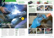
How to<br />
Baffle your sump<br />
Oil control is essential in a high performance engine<br />
but you don’t need a dry sump to get race-type control.<br />
We investigate a baffle system for our Crossflow sump.<br />
Words and Photos John Hill<br />
Before you<br />
start...<br />
Safety FIRST<br />
Always remember safety first when it<br />
comes to using power tools and welders,<br />
so that means goggles and gloves where<br />
necessary, and a decent welding mask —<br />
the automatic type is the best as this allows<br />
you to use both hands and be able to see<br />
what you are doing at all times. With power<br />
tools, remember to always use the correct<br />
guards and clamp the work piece securely.<br />
1 2<br />
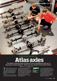
This is our standard front-bowl Crossflow sump,<br />
which essentially came with the standard<br />
spring-loaded pick-up pipe.<br />
save<br />
money<br />
and<br />
DIY!<br />
Naturally, it’s filthy, so Dave thoroughly cleans it<br />
first, completely de-greasing it so we have<br />
something to weld to.<br />
Crossflow sumps aren’t exactly<br />
race-orientated are they But the<br />
option is to spend loads of money<br />
and go dry sump instead. And that of<br />
course means a big, fat wad of cash which<br />
we can’t justify right now. So we thought<br />
we’d apply some race technology into the<br />
sump we’d got, which is destined for the<br />
underside of one of our project cars.<br />
Our next port of call was Retro Dave<br />
Colledge so he could apply his vast amount<br />
of expertise into the black oily tank that<br />
3<br />
Inside, you can see how basic it is — there’s<br />
virtually nothing there apart from a shallow vertical<br />
baffle to control the oil. We need more!<br />
will feed our engine in a slightly more<br />
efficient way. The result is that Dave’s<br />
designed a complete sump baffling system,<br />
which is now available as a kit — and in so<br />
doing, he guided us through the process of<br />
the important bits you need to know to<br />
keep your oil under control.<br />
But there’s more to it than just a bit of<br />
tin plate welded in place: Retro <strong>Ford</strong> Ltd’s<br />
is two-piece, so you can clean it out easily<br />
too. The boy’s thought about it and the<br />
results are good...<br />
4<br />
Info<br />
Contact:<br />
Retro <strong>Ford</strong> Ltd<br />
01536 747978<br />
www.retroford.co.uk<br />
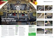
First thing to establish is the oil fill level — easy, as<br />
there’s witness marks. However a new sump may<br />
need filling first with the correct amount — use<br />
water at this point!<br />
Why baffle<br />
If you look at the front-bowl sump we’ve<br />
got, it’s basically a bucket in which to put oil.<br />
Inside that sits the oil pick-up pipe, which<br />
needs to be submerged in oil — this, as we<br />
all know, is the direct feed to the oil pump,<br />
which is continually sucking up oil,<br />
pumping it round the engine so it’s totally<br />
fed with lubrication.<br />
The pipe being completely covered is<br />
essential to prevent it sucking up pure air,<br />
which will result in run bearings. Therefore,<br />
if you don’t have effective baffles, in a high<br />
performance engine, it’ll promote just that.<br />
Our standard sump does have a bit of<br />
vertical baffling already, which helps to stop<br />
the oil slopping up the sides in a corner, but<br />
that’s nowhere near enough. Every time<br />
you corner and brake, oil is thrown<br />
upwards, either onto the sides of the sump<br />
or the crank itself. But once you add more<br />
power to your engine, you’ll be<br />
encouraging a touch more spirited driving,<br />
which of course will worsen the situation.<br />
The point about keeping the oil from<br />
splashing back onto the crank is an<br />
important one — the effect of this is that it’ll<br />
create drag on that component and slow it<br />
down. Not only that, but the oil will be<br />
aerated as the crank effectively turns into a<br />
kind of watermill churning up the oil —<br />
which we’ve already established promotes<br />
bearing failure.<br />
The simple solution is to put a cover over<br />
the top of the main oil reserve, known as a<br />
baffle, which will prevent it from moving<br />
upwards. But, it needs to be positioned in<br />
such a way that oil returning to the sump<br />
can drain into it and feed the oil pick-up. In<br />
addition, its placement is essential not only<br />
for oil control but it needs to be in such a<br />
way that it’s not contacting other<br />
components either — you don’t want it<br />
clouting the crank and rods!<br />
Dave Colledge’s Retro <strong>Ford</strong> has<br />
developed a two-piece system that allows<br />
the sump to be cleaned out. This can be a<br />
major problem as baffling usually means<br />
the oil pick-up’s totally encapsulated with<br />
sheet steel — sheet steel you can’t move.<br />
All that’s left is a hole to pass the pick-up<br />
through when fitting the sump pan back in<br />
place. In addition, there’s usually another<br />
hole for the dipstick too. Come clean-out<br />
time, you just can’t get in there to remove<br />
the nasties.<br />
Therefore, in this case, there’s an outer<br />
ring, which is located on the inside of the<br />
sump walls. Onto this is fitted the top baffle<br />
plate, which is bolted to the first by captive<br />
nuts — these need to be securely welded in<br />
place for obvious reasons. In turn, the bolts<br />
fitting the two together need spring<br />
washers plus locking fluid to guarantee<br />
they won’t part, throwing an enginedamaging<br />
component into the works.<br />
116 September 2010 September 2010 117
how to: sump baffling<br />
5<br />
6<br />
7<br />
When he’s worked out how far up the sump the oil<br />
comes, Dave measures the length...<br />
...Then the width — this time with dividers as you<br />
can’t get a ruler in there!<br />
Then transfer the two measurements into a trial<br />
piece of metal, bent at the ends...<br />
8<br />
9<br />
10<br />
...He has made two so we can check for both<br />
width and length before...<br />
...Dave transfers the basic measurements into a<br />
card template. Note: the baffle should end up no<br />
more than 12 mm above the fill level.<br />
Next we needed to establish the siting of the oil<br />
pick-up. This can be tricky because it’s a very tight<br />
fit in the block — ours is a dummy and difficult to<br />
get out again.<br />
11 12 13<br />
Then you need to check the fit of the oil pan —<br />
normally you’d need a maximum of 6 mm<br />
between the gauze and the bottom of the sump<br />
but ours is spring loaded...<br />
...So it touches the bottom (which is normal),<br />
where you’ll find a witness mark.<br />
With this established, we measure the<br />
dimensions of the pipe...<br />
14 15 16<br />
...Plus those of the head of the pick-up pipe gauze,<br />
which will establish the size of the hole needed in<br />
the baffle plate.<br />
Dave transfers the lot to the card template —<br />
although this is the actual baffle being checked on<br />
the dummy block!<br />
After we’ve made our templates and established<br />
the correct measurements, Dave transfers the lot<br />
into Auto Cad, makes a drawing and has it<br />
converted into steel at the laser cutters.<br />
September 2010 119
CFTech<br />
17<br />
18<br />
19<br />
The resulting two components bolt together so<br />
our next job is to weld in some captive nuts — the<br />
screws are temporary but...<br />
...The bolts on the back aren’t. Dave securely<br />
Mig-welds these to the back plate with the two<br />
bolted up to prevent distortion.<br />
Once cooled, we separate the two once more and<br />
begin fitting the outer ring in place at the height<br />
we established earlier.<br />
20<br />
21<br />
22<br />
Dave initially tacks the ring in place, then goes<br />
round and adds some strategic 25 mm long<br />
seam-welds — these don’t need welding shut at<br />
the gaps around to allow oil to feed in.<br />
23<br />
Finished — it is now ready to be bolted<br />
back onto the engine, which now has full<br />
oil control!<br />
Next job is to securely bolt the two together,<br />
which we do with stainless cap-head screws<br />
along with thread lock...<br />
...And to make doubly sure, spring washers too.<br />
You need as much insurance as possible to<br />
prevent the components coming loose — that<br />
equals engine wipe-out!<br />
120 September 2010