DPIA Differential Pressure Sensor Data Sheet - Trend
DPIA Differential Pressure Sensor Data Sheet - Trend DPIA Differential Pressure Sensor Data Sheet - Trend
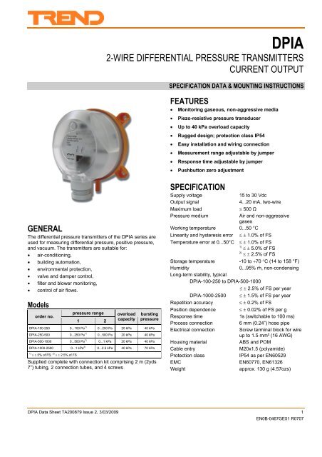
DPIA 2-WIRE DIFFERENTIAL PRESSURE TRANSMITTERS CURRENT OUTPUT SPECIFICATION DATA & MOUNTING INSTRUCTIONS FEATURES Monitoring gaseous, non-aggressive media Piezo-resistive pressure transducer Up to 40 kPa overload capacity Rugged design; protection class IP54 Easy installation and wiring connection Measurement range adjustable by jumper Response time adjustable by jumper Pushbutton zero adjustment GENERAL The differential pressure transmitters of the DPIA series are used for measuring differential pressure, positive pressure, and vacuum. The transmitters are suitable for: air-conditioning, building automation, environmental protection, valve and damper control, filter and blower monitoring, control of air flows. Models order no. pressure range 1 2 overload capacity bursting pressure DPIA-100-250 0...100 Pa 1) 0...250 Pa 20 kPa 40 kPa DPIA-250-500 0...250 Pa 1) 0...500 Pa 20 kPa 40 kPa DPIA-500-1000 0...500 Pa 1) 0...1 kPa 20 kPa 40 kPa DPIA-1000-2500 0...1 kPa 2) 0...2.5 kPa 40 kPa 70 kPa 1) 5% of FS; 2) 2.5% of FS Supplied complete with connection kit comprising 2 m (2yds 7”) tubing, 2 connection tubes, and 4 screws SPECIFICATION Supply voltage Output signal Maximum load Pressure medium 15 to 30 Vdc 4...20 mA, two-wire 500 Ω Air and non-aggressive gases Working temperature 0...50 °C Linearity and hysteresis error 1.0% of FS Temperature error at 0...50°C 1.0% of FS 1) 5.0% of FS 2) 2.5% of FS Storage temperature -10 to 70 C (14 to 158 °F) Humidity 0...95% rh, non-condensing Long-term stability, typical DPIA-100-250 to DPIA-500-1000 2.5% of FS per year DPIA-1000-2500 1.5% of FS per year Repetition accuracy 0.2% of FS Position dependence 0.02% of FS per g Response time 1s (switchable to 100 ms) Process connection 6 mm (0.24”) hose pipe Electrical connection Screw terminal block for wire up to 1.5 mm² (16 AWG) Housing material ABS and POM Cable entry M20x1.5 (polyamide) Protection class IP54 as per EN60529 EMC EN60770, EN61326 Weight approx. 130 g (4.57ozs) DPIA Data Sheet TA200879 Issue 2, 3/03/2009 1 EN0B-0467GE51 R0707
<strong>DPIA</strong><br />
2-WIRE DIFFERENTIAL PRESSURE TRANSMITTERS<br />
CURRENT OUTPUT<br />
SPECIFICATION DATA & MOUNTING INSTRUCTIONS<br />
FEATURES<br />
Monitoring gaseous, non-aggressive media<br />
<br />
<br />
<br />
<br />
<br />
<br />
<br />
Piezo-resistive pressure transducer<br />
Up to 40 kPa overload capacity<br />
Rugged design; protection class IP54<br />
Easy installation and wiring connection<br />
Measurement range adjustable by jumper<br />
Response time adjustable by jumper<br />
Pushbutton zero adjustment<br />
GENERAL<br />
The differential pressure transmitters of the <strong>DPIA</strong> series are<br />
used for measuring differential pressure, positive pressure,<br />
and vacuum. The transmitters are suitable for:<br />
air-conditioning,<br />
building automation,<br />
environmental protection,<br />
valve and damper control,<br />
filter and blower monitoring,<br />
control of air flows.<br />
Models<br />
order no.<br />
pressure range<br />
1 2<br />
overload<br />
capacity<br />
bursting<br />
pressure<br />
<strong>DPIA</strong>-100-250 0...100 Pa 1) 0...250 Pa 20 kPa 40 kPa<br />
<strong>DPIA</strong>-250-500 0...250 Pa 1) 0...500 Pa 20 kPa 40 kPa<br />
<strong>DPIA</strong>-500-1000 0...500 Pa 1) 0...1 kPa 20 kPa 40 kPa<br />
<strong>DPIA</strong>-1000-2500 0...1 kPa 2) 0...2.5 kPa 40 kPa 70 kPa<br />
1) 5% of FS; 2) 2.5% of FS<br />
Supplied complete with connection kit comprising 2 m (2yds<br />
7”) tubing, 2 connection tubes, and 4 screws<br />
SPECIFICATION<br />
Supply voltage<br />
Output signal<br />
Maximum load<br />
<strong>Pressure</strong> medium<br />
15 to 30 Vdc<br />
4...20 mA, two-wire<br />
500 Ω<br />
Air and non-aggressive<br />
gases<br />
Working temperature 0...50 °C<br />
Linearity and hysteresis error 1.0% of FS<br />
Temperature error at 0...50°C 1.0% of FS<br />
1)<br />
5.0% of FS<br />
2)<br />
2.5% of FS<br />
Storage temperature<br />
-10 to 70 C (14 to 158 °F)<br />
Humidity<br />
0...95% rh, non-condensing<br />
Long-term stability, typical<br />
<strong>DPIA</strong>-100-250 to <strong>DPIA</strong>-500-1000<br />
2.5% of FS per year<br />
<strong>DPIA</strong>-1000-2500 1.5% of FS per year<br />
Repetition accuracy<br />
0.2% of FS<br />
Position dependence 0.02% of FS per g<br />
Response time<br />
1s (switchable to 100 ms)<br />
Process connection<br />
6 mm (0.24”) hose pipe<br />
Electrical connection<br />
Screw terminal block for wire<br />
up to 1.5 mm² (16 AWG)<br />
Housing material<br />
ABS and POM<br />
Cable entry<br />
M20x1.5 (polyamide)<br />
Protection class<br />
IP54 as per EN60529<br />
EMC<br />
EN60770, EN61326<br />
Weight<br />
approx. 130 g (4.57ozs)<br />
<strong>DPIA</strong> <strong>Data</strong> <strong>Sheet</strong> TA200879 Issue 2, 3/03/2009 1<br />
EN0B-0467GE51 R0707
<strong>DPIA</strong><br />
<strong>Data</strong> <strong>Sheet</strong><br />
FUNCTION<br />
The <strong>DPIA</strong> Two-Wire <strong>Differential</strong> <strong>Pressure</strong> Transmitters are<br />
equipped with an integrated piezo-resistive pressure<br />
transducer designed so that the pressure to be measured is<br />
applied to a thin membrane made of monosilicon, thus<br />
deflecting it. The semiconductor resistors on the membrane<br />
detect this mechanical deflection and generate an electrical<br />
output signal. The arrangement of the resistors<br />
simultaneously compensates for the temperature response.<br />
The signal of the pressure transducer is converted into the<br />
output signal by high-gain operation amplifiers.<br />
The electrical output signal changes within the specified error<br />
limits in proportion to the applied pressure.<br />
NOTE: All <strong>DPIA</strong> Two-Wire <strong>Differential</strong> <strong>Pressure</strong><br />
Transmitters are factory pre-set to a response time<br />
of 1s (slow).<br />
NOTE: All <strong>DPIA</strong> Two-Wire <strong>Differential</strong> <strong>Pressure</strong><br />
Transmitters are factory pre-set to the lower<br />
pressure range 1.<br />
WIRING<br />
resistive load (ohms)<br />
permissible Vdc load<br />
permissible Vac load<br />
800<br />
600<br />
400<br />
200<br />
0<br />
16 18 20 22 24 26 28 30<br />
supply voltage (2-wire versions: Vdc, only)<br />
Fig. 2. Permissible load vs. supply voltage<br />
MOUNTING<br />
32<br />
storage positions<br />
for pin plugs<br />
Default: links fitted<br />
Range low<br />
Response slow<br />
high<br />
fast<br />
Zero Point Deviation:<br />
Disconnect hoses and press<br />
for 5 s to correct zero offset<br />
DISPOSAL<br />
Jumper yes<br />
Jumper no<br />
<strong>Differential</strong> <strong>Pressure</strong> Transmitter<br />
<strong>DPIA</strong>-100-250<br />
<strong>Pressure</strong> range 0 ... 100 Pa / 0 ... 250 Pa<br />
Overload capacity<br />
25 kPa<br />
Linearity and hyst. Error


