Amplifier and Data Converter Selection Guide
Amplifier and Data Converter Selection Guide
Amplifier and Data Converter Selection Guide
- No tags were found...

You also want an ePaper? Increase the reach of your titles
YUMPU automatically turns print PDFs into web optimized ePapers that Google loves.
48 <strong>Amplifier</strong>s<br />
➔<br />
Isolation <strong>Amplifier</strong>s<br />
There are many applications where it is<br />
desirable, even essential, that a sensor not<br />
have a direct (galvanic) electrical connection<br />
with the system to which it is supplying data<br />
in order to avoid either dangerous voltages or<br />
currents from one half of the system from<br />
damaging the other half. Such a system is<br />
said to be "isolated", <strong>and</strong> the area which<br />
passes a signal without galvanic connections<br />
is known as an "isolation barrier".<br />
Isolation barrier protection works in both<br />
directions, <strong>and</strong> may be needed in either half<br />
of the system, sometimes both. Common<br />
applications requiring isolation protection are<br />
3.3V, High-Speed Digital Isolators<br />
ISO721, ISO722<br />
those where sensors may accidentally<br />
encounter high voltages <strong>and</strong> the system it is<br />
driving must be protected. Or a sensor may<br />
need to be isolated from accidental high<br />
voltages arising downstream in order to<br />
protect its environment: examples include<br />
prevention of explosive gas ignition caused<br />
by sparks at sensor locations or protecting<br />
patients from electric shock by ECG, EEG <strong>and</strong><br />
EMG test <strong>and</strong> monitoring equipment. The<br />
ECG application may require isolation barriers<br />
in both directions: the patient must be<br />
protected from the very high voltages<br />
(>7.5kV) applied by the defibrillator, <strong>and</strong> the<br />
technician h<strong>and</strong>ling the device must be<br />
protected from unexpected feedback.<br />
Applications for Isolation <strong>Amplifier</strong>s<br />
• Sensor is at a high potential relative to<br />
other circuitry (or may become so under<br />
fault conditions)<br />
• Sensor may not carry dangerous voltages,<br />
irrespective of faults in other circuitry (e.g.<br />
patient monitoring <strong>and</strong> intrinsically safe<br />
equipment for use with explosive gases)<br />
• To break ground loops<br />
Get samples, datasheets, EVMs <strong>and</strong> app reports at: www.ti.com/sc/device/ISO721<br />
Key Features<br />
• 4000V isolation<br />
• Fail-safe output<br />
• Signaling rate up to 100Mbps<br />
• UL 1577, IEC 60747-5-2 (VDE 0884,<br />
Rev. 2), IEC 61010-1 <strong>and</strong> CSA Approved<br />
• 25kV/µs transient immunity<br />
Applications<br />
• Industrial fieldbus<br />
• Servo monitoring <strong>and</strong> control<br />
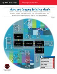
The ISO721 digital isolator is a logic input <strong>and</strong> output buffer separated by a silicon oxide (SiO 2 )<br />
insulation barrier that provides galvanic isolation of up to 4000V. Used in conjunction with<br />
isolated power supplies, the device prevents noise currents on a data bus or other circuits from<br />
entering the local ground <strong>and</strong> interfering with or damaging sensitive circuitry.<br />
A binary input signal is conditioned, translated to a balanced signal, then differentiated by the<br />
capacitive isolation barrier. Across the isolation barrier, a differential comparator receives the<br />
logic transition information, then sets or resets a flip-flop <strong>and</strong> the output circuit accordingly. A<br />
periodic update pulse is sent across the barrier to ensure the proper dc level of the output. If<br />
this dc-refresh pulse is not received for more than 4µs, the input is assumed to be unpowered<br />
or not functional <strong>and</strong> the fail-safe circuit drives the output to a logic high state.<br />
ISO721 functional<br />
block diagram.<br />
OSC<br />
+<br />
PWM<br />
DC Channel<br />
Isolation<br />
Barrier<br />
V REF<br />
Filter<br />
PWD<br />
Carrier<br />
Detect<br />
POR<br />
BIAS<br />
POR<br />
Isolation <strong>Amplifier</strong>s <strong>Selection</strong> <strong>Guide</strong><br />
IN<br />
Input<br />
+<br />
Filter<br />
AC Channel<br />
V REF<br />
(722 Only)<br />
<strong>Data</strong> MUX<br />
EN<br />
AC Detect<br />
3-State OUT<br />
Output<br />
Buffer<br />
Isolation Isolation Isolation Input Small-<br />
Voltage Cont Voltage Pulse/ Mode Gain Offset Voltage Signal<br />
Peak (DC) Test Peak Rejection DC Nonlinearity Drift (±µV/°C) B<strong>and</strong>width<br />
Device Description (V) (V) (dB) (typ) (%) (max) (max) (kHz) (typ) Package(s) Price *<br />
ISO122 1500V RMS Isolation, Buffer 2121 2400 140 0.02 200 50 DIP-16, SOIC-28 $9.40<br />
ISO124 1500V RMS Isolation, Buffer 2121 2400 140 0.01 200 50 DIP-16, SOIC-28 $7.20<br />
Digital Couplers<br />
Isolation Isolation Peak Working <strong>Data</strong> Transient Propagation<br />
Voltage Cont Voltage Pulse/ Transient Voltage Rate Immunity Delay PWD ICCQ<br />
Peak (DC) Test Peak Overvoltage VIORM (max) (min) at 5V (max) at 5V (max) at 5V (max) Supply<br />
Device Description (V) (V) VIOTM (V) (V) (Mbps) (KV/µs) (ns) (ns) (mA) Voltage Package(s) Price *<br />
ISO150 Dual Channel Bi-directional 1500 2400 — — 80 1.6 40 6 10 5V DIP-12, SO-12 $8.10<br />
Digital Isolator<br />
ISO721 Single Channel, 3.3V/5V — — 4000 560 100 25 24 2 13 3.3V, 5V SO-8 $1.65<br />
Digital Isolators<br />
ISO721M Single Channel, 3.3V/5V — — 4000 560 150 25 16 1 13 3.3V, 5V SO-8 $1.65<br />
Digital Isolators<br />
* Suggested resale price in U.S. dollars in quantities of 1,000. New products are listed in bold red.<br />
<strong>Amplifier</strong> <strong>and</strong> <strong>Data</strong> <strong>Converter</strong> <strong>Selection</strong> <strong>Guide</strong> Texas Instruments 3Q 2006