Amplifier and Data Converter Selection Guide
Amplifier and Data Converter Selection Guide
Amplifier and Data Converter Selection Guide
- No tags were found...

You also want an ePaper? Increase the reach of your titles
YUMPU automatically turns print PDFs into web optimized ePapers that Google loves.
30<br />
<strong>Amplifier</strong>s<br />
➔<br />
Instrumentation <strong>Amplifier</strong>s<br />
Single-Supply, RRIO, Low-Offset, Low-Drift Instrumentation <strong>Amplifier</strong>s<br />
INA326, INA327 (Shutdown Version)<br />
Get samples, datasheets <strong>and</strong> app reports at: www.ti.com/sc/device/INA326 <strong>and</strong> www.ti.com/sc/device/INA327<br />
Key Features<br />
• Low offset: 100µV (max)<br />
• Low offset drift: 0.4µV/°C (max)<br />
• Excellent long-term stability<br />
• Very-low 1/f noise<br />
• True rail-to-rail I/O<br />
• Input common-mode range:<br />
• 20mV below negative rail<br />
• 100mV above positive rail<br />
• Wide output swing: within 10mV of rails<br />
• Single supply range: +2.7V to +5.5V<br />
• Temp range: –40°C to +125°C (INA327)<br />
• Packaging: MSOP-8, MSOP-10<br />
Applications<br />
• Low-level transducer amplifier for<br />
bridges, load cells, thermocouples<br />
• Wide dynamic range sensor<br />
measurements<br />
• High-resolution test systems<br />
• Weigh scales<br />
• Multi-channel data acquisition systems<br />
• Medical instrumentation<br />
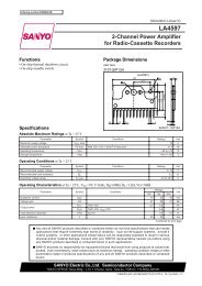
The INA326 uses a new, unique internal circuit topology that provides true rail-to-rail input. Unlike<br />
other instrumentation amplifiers, it can linearly process inputs to 20mV below the negative power<br />
supply rail, <strong>and</strong> 100mV above the positive power supply rail. Conventional instrumentation amplifier<br />
input topologies cannot deliver such wide dynamic performance.<br />
In most instrumentation amplifiers, the ability to reject common-mode signals is derived through a<br />
combination of input amplifier CMR <strong>and</strong> accurately matched resistor ratios. The INA326 converts the<br />
input voltage to a current, allowing the input amplifiers to accurately match <strong>and</strong> reject common-mode<br />
input voltage <strong>and</strong> power supply variation without the use of resistors.<br />
V IN–<br />
Current Monitor<br />
I R1<br />
Current Monitor<br />
I R1 R 1<br />
I R1 Current Monitor<br />
V IN+<br />
A1<br />
A2<br />
2I R1<br />
Current Monitor<br />
V+ V–<br />
0.1µF<br />
IR1<br />
2I R1<br />
V 0<br />
2I R1<br />
2I R1<br />
2I R1<br />
A3<br />
INA326<br />
INA326 functional block diagram.<br />
R 2 C 2<br />
IA COMMON<br />
2MHz B<strong>and</strong>width, Rail-to-Rail Output, Single-Supply Instrumentation <strong>Amplifier</strong>s<br />
INA332, INA2332<br />
Get samples, datasheets, <strong>and</strong> app reports at: www.ti.com/sc/device/INA332 <strong>and</strong> www.ti.com/sc/device/INA2332<br />
Key Features<br />
• High gain accuracy: G = 5, 0.07%, 2ppm/°C<br />
• High CMRR: 73dB DC, 50dB at 45kHz<br />
• Low bias current: 0.05pA<br />
• B<strong>and</strong>width: 2MHz<br />
• Slew rate: 5Vµs<br />
• Rail-to-rail output swing: (V+) –0.02V<br />
• Low quiescent current: 490µA max/ch<br />
• Packaging: MSOP-8 single, SSOP-14 dual<br />
Applications<br />
• Industrial sensors:<br />
• Bridge, RTD, thermocouple, position<br />
• Physiological amplifiers: ECG, EEG, EMG<br />
• Field utility meters<br />
• PCMCIA cards<br />
• Test equipment<br />
• Automotive instrumentation<br />
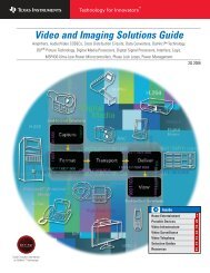
The INA332 <strong>and</strong> INA2332 are rail-to-rail output, low-power, gain = 5, CMOS instrumentation<br />
amplifiers that operate on 2.7V to 5.5V supplies. They offer excellent speed/power ratio with<br />
2MHz b<strong>and</strong>width <strong>and</strong> 490µA/channel supply current. Available shutdown/enable function adds<br />
additional power savings by reducing current to 0.01µA.<br />
V REF<br />
V IN –<br />
V IN +<br />
40kΩ<br />
G = 5 + (5R 2 /R 1 )<br />
10kΩ<br />
INA332 functional block diagram.<br />
R 1<br />
–<br />
10kΩ<br />
–<br />
A 1 –<br />
A 3<br />
+<br />
A 2<br />
+<br />
+<br />
V+<br />
V–<br />
40kΩ<br />
R G<br />
Shutdown<br />
R 2<br />
INA332<br />
V OUT<br />
<strong>Amplifier</strong> <strong>and</strong> <strong>Data</strong> <strong>Converter</strong> <strong>Selection</strong> <strong>Guide</strong> Texas Instruments 3Q 2006