

Heavy Duty Balanced Opposed Compressors - Ariel Corporation
Heavy Duty Balanced Opposed Compressors - Ariel Corporation
Heavy Duty Balanced Opposed Compressors - Ariel Corporation

You also want an ePaper? Increase the reach of your titles
YUMPU automatically turns print PDFs into web optimized ePapers that Google loves.
FOR MODELS: JGZ AND JGU SECTION 4 LUBRICATION<br />
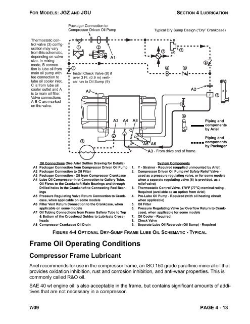
Thermostatic control<br />
valve (3) configuration<br />
may vary<br />
from this schematic,<br />
depending on valve<br />
size. In mixing<br />
mode, B connection<br />
is lube oil from<br />
main oil pump with<br />
tee connection to<br />
lube oil cooler inlet,<br />
C is from lube oil<br />
cooler outlet and A<br />
is to main oil filter.<br />
Valve connections<br />
A-B-C are marked<br />
on the valve.<br />
Packager Connection to<br />
Compressor Driven Oil Pump<br />
1 2<br />
8<br />
Install Check Valve (8) if<br />
over 3 Ft. (0.9 m) vertical<br />
run to Oil Sump (9)<br />
Frame Oil Operating Conditions<br />
Compressor Frame Lubricant<br />
9<br />
A7<br />
A1<br />
A3 A4 A8<br />
Oil Connections (See <strong>Ariel</strong> Outline Drawing for Details)<br />
A1 Packager Connection from Compressor Driven Oil Pump<br />
A2 Packager Connection to Oil Filter<br />
A3 Packager Connection - Oil from Compressor Crankcase<br />
A4 Lube Oil Compressor-Inlet-Connection to Gallery Tube.<br />
Oil Flows to the Crankshaft Main Bearings and through<br />
Drilled holes in the Crankshaft to Connecting Rod Bearings<br />
A5 Pressure Regulating Valve Return Connection to Crankcase,<br />
when applicable on some models<br />
A6 Filter Vent Return Connection to the Crankcase, when<br />
applicable on some models<br />
A7 Oil Tubing Connections from Frame Gallery Tube to Top<br />
& Bottom of the Crosshead Guides to Lubricate Crossheads<br />
A8 Compressor Crankcase Oil Drain<br />
A5 A6<br />
Typical Dry Sump Design (“Dry” Crankcase)<br />
4 8<br />
<strong>Ariel</strong> recommends for use in the compressor frame, an ISO 150 grade paraffinic mineral oil that<br />
provides oxidation inhibition, rust and corrosion inhibition, and anti-wear properties. This is<br />
commonly called R&O oil.<br />
SAE 40 wt engine oil is also acceptable in the frame, but contains significant amounts of additives<br />
that are not necessary in a compressor.<br />
7/09 PAGE 4 - 13<br />
7<br />
B<br />
A<br />
C<br />
3<br />
6<br />
A2<br />
A3 - From drive end of frame.<br />
8<br />
F<br />
5<br />
Piping and<br />
components<br />
by <strong>Ariel</strong><br />
Piping and<br />
components<br />
by Packager<br />
System Components<br />
1. Y - Strainer - Required (supplied unmounted by <strong>Ariel</strong>)<br />
2. Compressor Driven Oil Pump (w/ Safety Relief Valve -<br />
used as a pressure regulating valve, or for some models<br />
when a separate regulating valve (6) is provided, as a<br />
relief valve)<br />
3. Thermostatic Control Valve, 170°F (77°C) nominal rating -<br />
Required (available as an option from <strong>Ariel</strong>)<br />
4. Pre-Lube Oil Pump - Required (with oil heating circuit<br />
when applicable)<br />
5. Oil Filter<br />
6. Pressure Regulating Valve (w/ Overflow Return to Crankcase),<br />
when applicable for some models<br />
7. Oil Cooler - Required<br />
8. Check Valve<br />
9. Separate Lube Oil Reservoir (Oil Sump) - Required<br />
FIGURE 4-4 OPTIONAL DRY-SUMP FRAME LUBE OIL SCHEMATIC - TYPICAL


