

Heavy Duty Balanced Opposed Compressors - Ariel Corporation
Heavy Duty Balanced Opposed Compressors - Ariel Corporation
Heavy Duty Balanced Opposed Compressors - Ariel Corporation

You also want an ePaper? Increase the reach of your titles
YUMPU automatically turns print PDFs into web optimized ePapers that Google loves.
FOR MODELS: JGZ AND JGU SECTION 4 LUBRICATION<br />
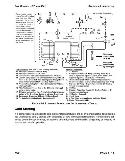
Thermostatic control<br />
valve (3) configuration<br />
may vary from this<br />
schematic, depending<br />
on valve size. In mixing<br />
mode, B connection<br />
is lube oil from<br />
main oil pump with tee<br />
connection to lube oil<br />
cooler inlet, C is from<br />
lube oil cooler outlet<br />
and A is to main oil filter.<br />
Valve connections<br />
A-B-C are marked on<br />
the valve.<br />
Cold Starting<br />
1 2<br />
A7<br />
A9<br />
A1<br />
A3 A4 A8<br />
Oil Connections (See <strong>Ariel</strong> Outline Drawing for Details)<br />
A1 Packager Connection from Oil Pump<br />
A2 Packager Connection to Oil Filter<br />
A3 Oil Connection from Compressor Crankcase (Oil Sump)<br />
A4 Lube Oil Compressor-Inlet-Connection to Gallery Tube. Oil<br />
Flows to the Crankshaft Main Bearings and through Drilled<br />
holes in the Crankshaft to Connecting Rod Bearings<br />
A5 Pressure Regulating Valve return Connection to Oil Sump,<br />
when applicable.<br />
A6 Filter Vent return Connection to the Oil Sump, when applicable<br />
on some models<br />
A7 Oil tubing connections from Frame Gallery Tube to top and<br />
bottom of the Crosshead Guides to lubricate Crossheads<br />
A8 Compressor Crankcase Oil Drain (Oil Sump Drain)<br />
A9 Pre-Lube/Recirculation/Heater Connections (4)<br />
10<br />
Optional<br />
Heater Circuit<br />
A5 A6<br />
4 9 8<br />
If a compressor is exposed to cold ambient temperatures, the oil system must be designed so<br />
the unit may be safely started with adequate oil flow to the journal bearings. Temperature controlled<br />
cooler by-pass valves, oil heaters, cooler louvers and even buildings may be needed to<br />
ensure successful operation.<br />
7/09 PAGE 4 - 11<br />
7<br />
A9<br />
B<br />
A<br />
C<br />
3<br />
6<br />
Typical Wet Sump Design<br />
A2<br />
8<br />
F<br />
5<br />
Piping and<br />
components<br />
by <strong>Ariel</strong><br />
Piping and<br />
components<br />
by Packager<br />
System Components<br />
1. Y - Strainer<br />
2. Compressor Driven Oil Pump (w/ Safety Relief Valve -<br />
used as a pressure regulating valve, or for models with a<br />
separate regulating valve (6), as a relief valve)<br />
3. Thermostatic Control Valve, 170°F (77°C) nominal rating -<br />
Required (available as an purchase separately from <strong>Ariel</strong>)<br />
4. Pre-Lube Oil Pump - Required (shown with Oil Heating<br />
Circuit, when applicable)<br />
5. Oil Filter<br />
6. Pressure Regulating Valve (with Overflow Return to Oil<br />
Sump), when applicable.<br />
7. Oil Cooler - Required<br />
8. Check Valve<br />
9. 3-Way Valve, when applicable for Heater Circuit<br />
10. Heater (When Applicable)<br />
FIGURE 4-3 STANDARD FRAME LUBE OIL SCHEMATIC - TYPICAL


