Heavy Duty Balanced Opposed Compressors - Ariel Corporation
Heavy Duty Balanced Opposed Compressors - Ariel Corporation Heavy Duty Balanced Opposed Compressors - Ariel Corporation
FOR MODELS: JGZ AND JGU SECTION 4 LUBRICATION ratings of Ariel filters. For this reason, Ariel does not recommend after market filters. Exercise caution if an after market filter is installed. Do not use a by-pass type filter. Pressure gauges are provided for monitoring pressure drop across the filter. Differential pressure is the primary indication of a plugged filter. Compressor Prelube Pump An automated compressor pre-lube system is strongly recommended for all Ariel compressors to extend bearing life and reduce operating costs. Compressors that meet any of the following criteria are required to have an automated pre-lube system to provide oil flow prior to start-up: 1. Electric motor driven compressors. 2. Unattended-start compressors, regardless of driver type. 3. All large frame compressor models (JGC, JGD, JGZ, JGU, JGB, JGV, KBB and KBV). Automated compressor pre-lube systems must be designed and sized to provide 10 psig (0.7 bar g ) minimum pressure for a minimum of 30 seconds prior to starting, at the inlet to the oil gallery (after the filter), with minimum start-up oil viscosity and maximum allowable filter differential pressure. It is suggested that the prelube pump be sized at approximately 25% of the frame oil pump capacity. Reference Technical Manual, Section 1, Frame Specification Tables for frame oil pump flow rates, or see the Electronic Databook in the Ariel Performance Program. The purpose is to be sure there is oil flow to all bearings and bushings, and the clearances are filled with oil prior to start-up. A start permissive is desirable to sense for minimum required pressure/time at the inlet to the oil gallery. Automated systems are to provide for shutdown if 35 psig (2.4 bar g ) oil pressure is not achieved within 10 seconds after the initiation of start-up (from when crankshaft starts to turn). If a compressor will not start or shuts down at start-up due to low oil pressure, do not attempt to re-start until the cause of low pressure is corrected. Engine driven compressors with manual pre-lube pumps are to be adequately pre-lubed prior to starting. If 35 psig (2.4 bar g ) oil pressure is not achieved within 10 seconds after reaching engine idle speed, shutdown the compressor and correct the cause. Repeat manual pre-lube prior to each cranking for start-up. Pre-lube pumps are to be located prior to the oil filter. When oil pressure exceeds 35 psig (2.4 bar g ) at start-up, a low oil pressure shutdown set at 35 psig (2.4 bar g ) must be active for all compressors. Oil Heaters Frame oil heaters may be needed if the compressor must be started in cold weather applications. Depending on the operational aspects of the compressor, one possible heating mode is to maintain the temperature in the compressor frame to a minimum temperature so that the compressor can be started immediately if needed, see Table 4-1. Another mode is to heat the oil from ambient to a minimum temperature prior to starting, see Table 4-2. The specific application requirements will determine which heating mode is necessary. Circulation type heaters are recommended. All compressor models have at least one connection for a heater. Four and Six throw frames have two locations. The maximum allowable wattage per unit area for an immersion heater is 15 W/in 2 (2.3 W/cm 2 ). This limit will prevent oil 7/09 PAGE 4 - 9
FOR MODELS: JGZ AND JGU SECTION 4 LUBRICATION from coking on the heater element and reducing the efficiency of the heater. It will also prevent the coked oil particles from contaminating the remaining oil. JGU:Z, JGB:V and KBB:V models are designed to use circulation heating only. MODEL TABLE 4-1 HEAT REQUIRED TO MAINTAIN MINIMUM FRAME TEMPERATURE MULTIPLY TIMES DIFFERENTIAL BETWEEN OIL & AMBIENT TEMPERATURE Lube Oil Analysis Sampling Point 2-THROW 4-THROW 6-THROW kW/°F (kW/°C) kW/°F (kW/°C) kW/°F (kW/°C) JGM:N:Q:P 0.0086 (0.0155) --- --- --- --- JG:A 0.0094 (0.0170) 0.0179 (0.0322) 0.0261 (0.0470) JGW:R:J 0.0147 (0.0265) 0.0289 (0.0520) 0.0419 (0.0754) JGH:E:K:T 0.0252 (0.0454) 0.0492 (0.0886) 0.0731 (0.1316) JGC:D 0.0392 (0.0706) 0.0722 (0.1300) 0.1044 (0.1880) JGU:Z 0.0534 (0.0961) 0.0944 (0.1700) 0.1319 (0.2374) JGB:V & KBB:V --- --- 0.1295 (0.2331) 0.1768 (0.3182) MODEL TABLE 4-2 HEAT REQUIRED TO WARM COLD COMPRESSOR FRAME & OIL MULTIPLY TIMES TEMPERATURE RISE DIVIDED BY TIME (h) 2-THROW 4-THROW 6-THROW kW-h/°F (kW-h/°C) kW-h/°F (kW-h/°C) kW-h/°F (kW-h/°C) JGM:N:Q:P 0.0275 (0.0495) --- --- --- --- JG:A 0.0352 (0.0634) 0.0818 (0.1472) 0.1347 (0.3425) JGW:R:J 0.0591 (0.1064) 0.1212 (0.2182) 0.1832 (0.3298) JGH:E 0.1368 (0.2462) 0.2962 (0.5332) 0.4526 (0.8147) JGK:T 0.1494 (0.2689) 0.3024 (0.5832) 0.4526 (0.8147) JGC:D 0.2684 (0.4831) 0.5614 (1.0105) 0.8074 (1.4533) JGU:Z 0.4496 (0.8093) 0.8900 (1.6020) 1.2421 (2.2358) JGB:V & KBB:V --- --- 1.4176 (2.5517) 2.0224 (3.6403) A sampling point should be installed at a convenient location between the oil pump and the filter. This should be installed at an easily accessible location and designed to minimize the amount of dirt or debris that can collect around the dispensing point. A needle valve should be used to better control the flow of the pressurized oil. PAGE 4 - 10 7/09
- Page 23 and 24: FOR MODELS: JGZ AND JGU SECTION 1 -
- Page 25 and 26: FOR MODELS: JGZ AND JGU SECTION 1 -
- Page 27 and 28: FOR MODELS: JGZ AND JGU SECTION 1 -
- Page 29 and 30: FOR MODELS: JGZ AND JGU SECTION 1 -
- Page 31 and 32: FOR MODELS: JGZ AND JGU SECTION 1 -
- Page 33 and 34: FOR MODELS: JGZ AND JGU SECTION 1 -
- Page 35 and 36: FOR MODELS: JGZ AND JGU SECTION 1 -
- Page 37 and 38: FOR MODELS: JGZ AND JGU SECTION 2 -
- Page 39 and 40: FOR MODELS: JGZ AND JGU SECTION 2 -
- Page 41 and 42: FOR MODELS: JGZ AND JGU SECTION 2 -
- Page 43 and 44: FOR MODELS: JGZ AND JGU SECTION 2 -
- Page 45 and 46: FOR MODELS: JGZ AND JGU SECTION 2 -
- Page 47 and 48: FOR MODELS: JGZ AND JGU SECTION 2 -
- Page 49 and 50: FOR MODELS: JGZ AND JGU SECTION 2 -
- Page 51 and 52: FOR MODELS: JGZ AND JGU SECTION 3 -
- Page 53 and 54: FOR MODELS: JGZ AND JGU SECTION 3 -
- Page 55 and 56: FOR MODELS: JGZ AND JGU SECTION 3 -
- Page 57 and 58: FOR MODELS: JGZ AND JGU SECTION 3 -
- Page 59 and 60: FOR MODELS: JGZ AND JGU SECTION 3 -
- Page 61 and 62: FOR MODELS: JGZ AND JGU SECTION 3 -
- Page 63 and 64: FOR MODELS: JGZ AND JGU SECTION 3 -
- Page 65 and 66: FOR MODELS: JGZ AND JGU SECTION 3 -
- Page 67 and 68: FOR MODELS: JGZ AND JGU SECTION 4 L
- Page 69 and 70: FOR MODELS: JGZ AND JGU SECTION 4 L
- Page 71 and 72: FOR MODELS: JGZ AND JGU SECTION 4 L
- Page 73: FOR MODELS: JGZ AND JGU SECTION 4 L
- Page 77 and 78: FOR MODELS: JGZ AND JGU SECTION 4 L
- Page 79 and 80: FOR MODELS: JGZ AND JGU SECTION 4 L
- Page 81 and 82: FOR MODELS: JGZ AND JGU SECTION 4 L
- Page 83 and 84: FOR MODELS: JGZ AND JGU SECTION 4 L
- Page 85 and 86: FOR MODELS: JGZ AND JGU SECTION 4 L
- Page 87 and 88: FOR MODELS: JGZ AND JGU SECTION 4 L
- Page 89 and 90: FOR MODELS: JGZ AND JGU SECTION 4 L
- Page 91 and 92: FOR MODELS: JGZ AND JGU SECTION 4 L
- Page 93 and 94: FOR MODELS: JGZ AND JGU SECTION 4 L
- Page 95 and 96: FOR MODELS: JGZ AND JGU SECTION 4 L
- Page 97 and 98: FOR MODELS: JGZ AND JGU SECTION 4 L
- Page 99 and 100: FOR MODELS: JGZ AND JGU SECTION 4 L
- Page 101 and 102: FOR MODELS: JGZ AND JGU SECTION 4 L
- Page 103 and 104: FOR MODELS: JGZ AND JGU SECTION 4 L
- Page 105 and 106: FOR MODELS: JGZ AND JGU SECTION 4 L
- Page 107 and 108: FOR MODELS: JGZ AND JGU SECTION 4 L
- Page 109 and 110: FOR MODELS: JGZ AND JGU SECTION 4 L
- Page 111 and 112: FOR MODELS: JGZ AND JGU SECTION 4 L
- Page 113 and 114: FOR MODELS: JGZ AND JGU SECTION 4 L
- Page 115 and 116: FOR MODELS: JGZ AND JGU SECTION 4 L
- Page 117 and 118: FOR MODELS: JGZ AND JGU SECTION 4 L
- Page 119 and 120: FOR MODELS: JGZ AND JGU SECTION 4 L
- Page 121 and 122: FOR MODELS: JGZ AND JGU SECTION 4 L
- Page 123 and 124: FOR MODELS: JGZ AND JGU SECTION 5 -
FOR MODELS: JGZ AND JGU SECTION 4 LUBRICATION<br />
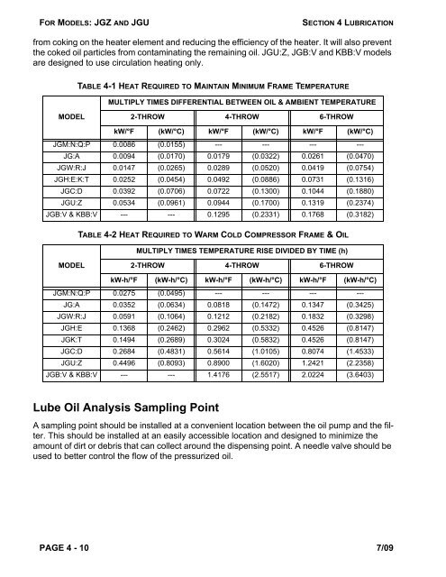
from coking on the heater element and reducing the efficiency of the heater. It will also prevent<br />
the coked oil particles from contaminating the remaining oil. JGU:Z, JGB:V and KBB:V models<br />
are designed to use circulation heating only.<br />
MODEL<br />
TABLE 4-1 HEAT REQUIRED TO MAINTAIN MINIMUM FRAME TEMPERATURE<br />
MULTIPLY TIMES DIFFERENTIAL BETWEEN OIL & AMBIENT TEMPERATURE<br />
Lube Oil Analysis Sampling Point<br />
2-THROW 4-THROW 6-THROW<br />
kW/°F (kW/°C) kW/°F (kW/°C) kW/°F (kW/°C)<br />
JGM:N:Q:P 0.0086 (0.0155) --- --- --- ---<br />
JG:A 0.0094 (0.0170) 0.0179 (0.0322) 0.0261 (0.0470)<br />
JGW:R:J 0.0147 (0.0265) 0.0289 (0.0520) 0.0419 (0.0754)<br />
JGH:E:K:T 0.0252 (0.0454) 0.0492 (0.0886) 0.0731 (0.1316)<br />
JGC:D 0.0392 (0.0706) 0.0722 (0.1300) 0.1044 (0.1880)<br />
JGU:Z 0.0534 (0.0961) 0.0944 (0.1700) 0.1319 (0.2374)<br />
JGB:V & KBB:V --- --- 0.1295 (0.2331) 0.1768 (0.3182)<br />
MODEL<br />
TABLE 4-2 HEAT REQUIRED TO WARM COLD COMPRESSOR FRAME & OIL<br />
MULTIPLY TIMES TEMPERATURE RISE DIVIDED BY TIME (h)<br />
2-THROW 4-THROW 6-THROW<br />
kW-h/°F (kW-h/°C) kW-h/°F (kW-h/°C) kW-h/°F (kW-h/°C)<br />
JGM:N:Q:P 0.0275 (0.0495) --- --- --- ---<br />
JG:A 0.0352 (0.0634) 0.0818 (0.1472) 0.1347 (0.3425)<br />
JGW:R:J 0.0591 (0.1064) 0.1212 (0.2182) 0.1832 (0.3298)<br />
JGH:E 0.1368 (0.2462) 0.2962 (0.5332) 0.4526 (0.8147)<br />
JGK:T 0.1494 (0.2689) 0.3024 (0.5832) 0.4526 (0.8147)<br />
JGC:D 0.2684 (0.4831) 0.5614 (1.0105) 0.8074 (1.4533)<br />
JGU:Z 0.4496 (0.8093) 0.8900 (1.6020) 1.2421 (2.2358)<br />
JGB:V & KBB:V --- --- 1.4176 (2.5517) 2.0224 (3.6403)<br />
A sampling point should be installed at a convenient location between the oil pump and the filter.<br />
This should be installed at an easily accessible location and designed to minimize the<br />
amount of dirt or debris that can collect around the dispensing point. A needle valve should be<br />
used to better control the flow of the pressurized oil.<br />
PAGE 4 - 10 7/09


