Heavy Duty Balanced Opposed Compressors - Ariel Corporation
Heavy Duty Balanced Opposed Compressors - Ariel Corporation
Heavy Duty Balanced Opposed Compressors - Ariel Corporation
You also want an ePaper? Increase the reach of your titles
YUMPU automatically turns print PDFs into web optimized ePapers that Google loves.
FOR MODELS: JGZ AND JGU SECTION 2 - COMPRESSOR INSTALLATION<br />
CAUTION: When lifting a compressor designed for lifting lugs, use ONLY <strong>Ariel</strong> provided or<br />
approved lugs. Be sure the lugs are held In place with the proper grade of cap screws, and<br />
properly tightened. Lifting cable spreaders are required perpendicular to crankshaft axis.<br />
Be sure the crane capacity is adequate.<br />
Setting the Compressor<br />
1. Be sure the skid is level.<br />
2. Move the compressor into place on the skid.<br />
3. Level stationary compressors to Table 2-1 requirements. For compressors subject to transient<br />
motion on ships or offshore platforms, level compressors to table requirements when at rest. Be<br />
sure the pre-grout alignment is relatively close so that the equipment movement will be minimal<br />
and within the bolting, foot, push pads or grout box allowance.<br />
4. Grout as required and allow grout to set.<br />
With the compressor cylinders mounted but unsupported and with no piping or pulsation<br />
damping bottles attached, tighten the frame foot hold down bolting to skid at full fastener<br />
torque. Refer to <strong>Ariel</strong> ER-26, Appendix A in the <strong>Ariel</strong> Packager’s Standards for proper frame<br />
foot torque values.<br />
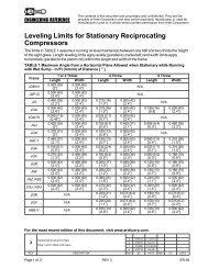
Leveling Limits for <strong>Compressors</strong><br />
The limits in Table 2-1 assume that the running oil level is maintained between one half and<br />
two-thirds the height of the sight glass, except for dry sump compressors. Length leveling<br />
limits apply axially (parallel to crankshaft) and width limits apply horizontally (parallel to the<br />
piston rod) within the length and width of the frame.<br />
TABLE 2-1 Maximum Angle from a Horizontal Plane for Leveling <strong>Compressors</strong><br />
Maximum Angle from a Horizontal Plane - In/Ft of Distance (mm/m) [ ° ]<br />
Frame<br />
1 or 2 Throw 4 Throw 6 Throw<br />
Length Width Length Width Length Width<br />
JGM:N 0.420 (35) [2°] 0.500 (42) [2.4°] N/A<br />
JGP:Q 0.500 (42) [2.4°] 0.500 (42) [2.4°] N/A<br />
JG 0.460 (38) [2.2°] 0.500 (42) [2.4°] 0.215 (18) [1.0°] 0.500 (42) [2.4°] N/A<br />
JGA 0.500 (42) [2.4°] 0.500 (42) [2.4°] 0.310 (26) [1.5°] 0.500 (42) [2.4°] 0.190 (16) [0.9] 0.500 (42) [2.4°]<br />
JGW:R 0.095 (7.9) [0.45°] 0.500 (42) [2.4°] 0.025 (2.1) [0.1°] 0.500 (42) [2.4°] N/A<br />
JGJ 0.420 (35) [2°] 0.500 (42) [2.4°] 0.105 (8.7) [0.5°] 0.450 (37) [2.1°] 0.065 (5.4) [0.3°] 0.460 (38) [2.2°]<br />
JGH 0.375 (31) [2°] 0.500 (42) [2.4°] 0.160 (13) [0.8°] 0.500 (42) [2.4°] N/A<br />
JGE:T 0.440 (37) [2.1°] 0.500 (42) [2.4°] 0.155 (13) [0.7°] 0.500 (42) [2.4°] 0.090 (7.5) [0.4°] 0.310 (26) [1.5°]<br />
JGK 0.105 (8.7) [0.5°] 0.500 (42) [2.4°] 0.035 (2.9) [0.2°] 0.500 (42) [2.4°] 0.020 (1.7) [0.1°] 0.310 (26) [1.5°]<br />
JGC 0.270 (22) [1.3°] 0.460 (38) [2.2°] 0.100 (8.3) [0.5°] 0.460 (38) [2.2°] 0.060 (5.0) [0.3°] 0.180 (15) [0.9°]<br />
JGD 0.500 (42) [2.4°] 0.460 (38) [2.2°] 0.205 (17) [1.0°] 0.460 (38) [2.2°] 0.125 (10) [0.6°] 0.180 (15) [0.9°]<br />
JGZ 0.500 (42) [2.4°] 0.500 (42) [2.4°] 0.380 (25) [1.8°] 0.500 (42) [2.4°] 0.240 (20) [1.1°] 0.500 (42) [2.4°]<br />
JGU 0.500 (42) [2.4°] 0.500 (42) [2.4°] 0.475 (40) [2.3°] 0.500 (42) [2.4°] 0.300 (25) [1.4°] 0.500 (42) [2.4°]<br />
JGB N/A 0.250 (21) [1.2°] 0.075 (6.2) [0.4°] 0.180 (15) [0.9°] 0.075 (6.2) [0.4°]<br />
PAGE 2 - 2 7/09


