Heavy Duty Balanced Opposed Compressors - Ariel Corporation
Heavy Duty Balanced Opposed Compressors - Ariel Corporation Heavy Duty Balanced Opposed Compressors - Ariel Corporation
FOR MODELS: JGZ AND JGU SECTION 5 - MAINTENANCE ring set individually onto the rod and check the total end gap. See “Types of Piston Rod Packing Rings” on Page 5-46 for end gap tolerances. If not within tolerance, replace with a new ring or file at a gap to restore total end gap to within tolerance. With the ring set on the rod, shine a light from behind the ring, if any light is observed between the ring and the rod, the ring set is not acceptable. 6. Make sure that each rod ring and cup is properly positioned and, unless nonlube, that rings are lightly coated with new clean lubricant before reassembly. Only use the same lubricant that is used in the force feed lube system. If nonlube, see “Cleaning, Handling and Thread Lubricants for Non-Lubricated Compressor Cylinders” on Page 5-66. Make sure the tie studs are completely screwed into the end cup. Examine all parts for unusual nicks or burrs which might interfere with the free floating of the rod ring in the cups. Particular care should be taken with rod rings made of soft materials, such as bronze or TFE, and it is extremely important that wiper rings be handled and installed so as to prevent damage to the scraping edges. If packing case is “water”-cooled, see “Water-Cooled Piston Rod Packing” on Page 5-54. Plastic Quill must be in Place (Ariel P/N A-12801) High-Pressure Plastic Quill Oil- Drip Lube Cup (Pre-2006) Lube Cup Identification Axial Groove (Beginning 2006) Grooved Oil- Drip Lube Cup (Beginning 2006) 1/4 in. (6 mm) FIGURE 5-30 PISTON ROD PACKING CASE LUBE CUPS 7. Parts should be laid out on a work bench so that they can be installed progressively with each in its correct position and the rod rings with their proper faces toward the pressure. Note that all rod ring segments are carefully lettered and must be assembled accordingly. This is most important in order to be sure of proper sealing. Install new tie stud nuts and tighten to the values given in Table 1-11 on Page 1-18. Make sure that all rings move freely, radially, in their grooves using your fingers. Side loaded WAT and AL rings will be snug and should be centered in the case when being installed, prior to tightening tie stud nuts. Side loaded rings should still move in the assembled case, using your fingers. Be sure these rings are centered. 8. For new installations, care must be given to the cleaning of all accumulated dirt in the lines and compressor because foreign material will lodge in the packing to become destructively abrasive. 9. Prior to installing the packing case into the cylinder, be sure gasket surfaces in the packing counter bore on the crank end of the cylinder are clean and not scratched. Install a new spiral wound gasket. Hold the gasket in the groove with super glue or grease when installing the packing case. If for non-lube service, only use the glue. 7/09 PAGE 5 - 45
FOR MODELS: JGZ AND JGU SECTION 5 - MAINTENANCE 10. Reinstall the complete packing case assembly with the oil supply point on top. Using the rod packing cap screws, pull the packing into place but do not tighten yet. 11. Reinstall the oil wiper gland(s) in the crosshead with the oil wiper packing. 12. Reinstall the piston and rod. Follow the steps under “Piston and Rod - Installation” on Page 5-40. 13. After the crosshead nut has been tightened, tighten the rod packing cap screws evenly to the recommended torque in Table 1-11 on Page 1-18 to be sure that the pressure packing comes up square on its nose gasket. Alignment is readily accomplished by the use of feelers to maintain a uniform clearance all around between the case bore and the rod. Rod packing cap screw tightening on high pressure cylinders requires the use of a torque multiplier. NOTE: THE FINAL TORQUE FOR THE ROD PACKING CAP SCREWS SHOULD BE REPEATED UNTIL NO TURNING OF THE FASTENERS IS OBSERVED. THE TORQUE ON THESE FASTENERS SHOULD BE RE-CHECKED AT THE NEXT SERVICE INTERVAL. 14. Retighten the small tie stud nuts. Reinstall the tubing connections and instruments (if applicable). Take care not to cross-thread the tubing nuts. Tubing nuts must be tight. NOTE: AFTER REINSTALLING THE PRESSURE PACKING, REFER TO “Force Feed Lubrication System” ON PAGE 4-49 FOR INSTRUCTIONS FOR PRIMING THE FORCE FEED LUBE SYSTEM. PRIMING SHOULD BE REPEATED EACH TIME A COMPRESSOR IS STARTED BECAUSE OIL LINES MAY HAVE BEEN BLED DURING DOWN TIME. FOLLOW INSTRUCTIONS IN “Force Feed Lubricator Adjustment” ON PAGE 3-14 FOR LUBRICATION RATES THAT ARE RECOM- MENDED FOR BREAK-IN OF A NEW MACHINE. BREAK-IN LUBE RATES ARE APPROXIMATELY TWICE THE NORMAL RATES - OR ONE-HALF THE NOR- MAL INDICATOR PIN CYCLE TIME. Types of Piston Rod Packing Rings Type "P" Pressure Breaker This is a single ring. It is cut radially into three equal segments. This ring breaks down or slows the gas flow without sealing it completely. See Figure 5-31. Letters toward pressure/cylinder Total End Gap - Installed: 0.058 to 0.064” (1.5 / to 1.7 mm) for PEEK 0.029 to 0.035” (0.7 to 0.9 mm) for Bronze & Cast Iron End gap should be maintained by replacing the ring. Radial Cut FIGURE 5-31 TYPE “P” PRESSURE BREAKER PAGE 5 - 46 7/09
- Page 115 and 116: FOR MODELS: JGZ AND JGU SECTION 4 L
- Page 117 and 118: FOR MODELS: JGZ AND JGU SECTION 4 L
- Page 119 and 120: FOR MODELS: JGZ AND JGU SECTION 4 L
- Page 121 and 122: FOR MODELS: JGZ AND JGU SECTION 4 L
- Page 123 and 124: FOR MODELS: JGZ AND JGU SECTION 5 -
- Page 125 and 126: FOR MODELS: JGZ AND JGU SECTION 5 -
- Page 127 and 128: FOR MODELS: JGZ AND JGU SECTION 5 -
- Page 129 and 130: FOR MODELS: JGZ AND JGU SECTION 5 -
- Page 131 and 132: FOR MODELS: JGZ AND JGU SECTION 5 -
- Page 133 and 134: FOR MODELS: JGZ AND JGU SECTION 5 -
- Page 135 and 136: FOR MODELS: JGZ AND JGU SECTION 5 -
- Page 137 and 138: FOR MODELS: JGZ AND JGU SECTION 5 -
- Page 139 and 140: FOR MODELS: JGZ AND JGU SECTION 5 -
- Page 141 and 142: FOR MODELS: JGZ AND JGU SECTION 5 -
- Page 143 and 144: FOR MODELS: JGZ AND JGU SECTION 5 -
- Page 145 and 146: FOR MODELS: JGZ AND JGU SECTION 5 -
- Page 147 and 148: FOR MODELS: JGZ AND JGU SECTION 5 -
- Page 149 and 150: FOR MODELS: JGZ AND JGU SECTION 5 -
- Page 151 and 152: FOR MODELS: JGZ AND JGU SECTION 5 -
- Page 153 and 154: FOR MODELS: JGZ AND JGU SECTION 5 -
- Page 155 and 156: FOR MODELS: JGZ AND JGU SECTION 5 -
- Page 157 and 158: FOR MODELS: JGZ AND JGU SECTION 5 -
- Page 159 and 160: FOR MODELS: JGZ AND JGU SECTION 5 -
- Page 161 and 162: FOR MODELS: JGZ AND JGU SECTION 5 -
- Page 163 and 164: FOR MODELS: JGZ AND JGU SECTION 5 -
- Page 165: FOR MODELS: JGZ AND JGU SECTION 5 -
- Page 169 and 170: FOR MODELS: JGZ AND JGU SECTION 5 -
- Page 171 and 172: FOR MODELS: JGZ AND JGU SECTION 5 -
- Page 173 and 174: FOR MODELS: JGZ AND JGU SECTION 5 -
- Page 175 and 176: FOR MODELS: JGZ AND JGU SECTION 5 -
- Page 177 and 178: FOR MODELS: JGZ AND JGU SECTION 5 -
- Page 179 and 180: FOR MODELS: JGZ AND JGU SECTION 5 -
- Page 181 and 182: FOR MODELS: JGZ AND JGU SECTION 5 -
- Page 183 and 184: FOR MODELS: JGZ AND JGU SECTION 5 -
- Page 185 and 186: FOR MODELS: JGZ AND JGU SECTION 5 -
- Page 187 and 188: FOR MODELS: JGZ AND JGU SECTION 5 -
- Page 189 and 190: FOR MODELS: JGZ AND JGU SECTION 5 -
- Page 191 and 192: FOR MODELS: JGZ AND JGU SECTION 6 -
- Page 193 and 194: FOR MODELS: JGZ AND JGU SECTION 6 -
- Page 195 and 196: FOR MODELS: JGZ AND JGU SECTION 6 -
- Page 197 and 198: FOR MODELS: JGZ AND JGU SECTION 6 -
- Page 199 and 200: FOR MODELS: JGZ AND JGU SECTION 7 -
- Page 201 and 202: FOR MODELS: JGZ AND JGU SECTION 7 -
- Page 203 and 204: FOR MODELS: JGZ AND JGU SECTION 7 -
- Page 205 and 206: FOR MODELS: JGZ AND JGU SECTION 7 -
- Page 207 and 208: FOR MODELS: JGZ AND JGU SECTION 7 -
- Page 209 and 210: FOR MODELS: JGZ AND JGU SECTION 7 -
- Page 211: FOR MODELS: JGZ AND JGU SECTION 7 -
FOR MODELS: JGZ AND JGU SECTION 5 - MAINTENANCE<br />
10. Reinstall the complete packing case assembly with the oil supply point on top.<br />
Using the rod packing cap screws, pull the packing into place but do not tighten<br />
yet.<br />
11. Reinstall the oil wiper gland(s) in the crosshead with the oil wiper packing.<br />
12. Reinstall the piston and rod. Follow the steps under “Piston and Rod - Installation”<br />
on Page 5-40.<br />
13. After the crosshead nut has been tightened, tighten the rod packing cap screws<br />
evenly to the recommended torque in Table 1-11 on Page 1-18 to be sure that<br />
the pressure packing comes up square on its nose gasket. Alignment is readily<br />
accomplished by the use of feelers to maintain a uniform clearance all around<br />
between the case bore and the rod. Rod packing cap screw tightening on high<br />
pressure cylinders requires the use of a torque multiplier.<br />
NOTE: THE FINAL TORQUE FOR THE ROD PACKING CAP SCREWS SHOULD BE<br />
REPEATED UNTIL NO TURNING OF THE FASTENERS IS OBSERVED. THE<br />
TORQUE ON THESE FASTENERS SHOULD BE RE-CHECKED AT THE NEXT<br />
SERVICE INTERVAL.<br />
14. Retighten the small tie stud nuts. Reinstall the tubing connections and instruments<br />
(if applicable). Take care not to cross-thread the tubing nuts. Tubing nuts<br />
must be tight.<br />
NOTE: AFTER REINSTALLING THE PRESSURE PACKING, REFER TO “Force Feed<br />
Lubrication System” ON PAGE 4-49 FOR INSTRUCTIONS FOR PRIMING THE<br />
FORCE FEED LUBE SYSTEM. PRIMING SHOULD BE REPEATED EACH TIME<br />
A COMPRESSOR IS STARTED BECAUSE OIL LINES MAY HAVE BEEN BLED<br />
DURING DOWN TIME. FOLLOW INSTRUCTIONS IN “Force Feed Lubricator<br />
Adjustment” ON PAGE 3-14 FOR LUBRICATION RATES THAT ARE RECOM-<br />
MENDED FOR BREAK-IN OF A NEW MACHINE. BREAK-IN LUBE RATES ARE<br />
APPROXIMATELY TWICE THE NORMAL RATES - OR ONE-HALF THE NOR-<br />
MAL INDICATOR PIN CYCLE TIME.<br />
Types of Piston Rod Packing Rings<br />
Type "P" Pressure Breaker<br />
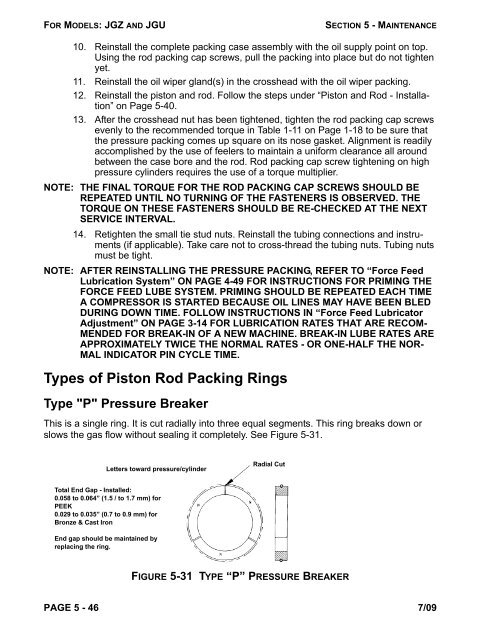
This is a single ring. It is cut radially into three equal segments. This ring breaks down or<br />
slows the gas flow without sealing it completely. See Figure 5-31.<br />
Letters toward pressure/cylinder<br />
Total End Gap - Installed:<br />
0.058 to 0.064” (1.5 / to 1.7 mm) for<br />
PEEK<br />
0.029 to 0.035” (0.7 to 0.9 mm) for<br />
Bronze & Cast Iron<br />
End gap should be maintained by<br />
replacing the ring.<br />
Radial Cut<br />
FIGURE 5-31 TYPE “P” PRESSURE BREAKER<br />
PAGE 5 - 46 7/09


