

Heavy Duty Balanced Opposed Compressors - Ariel Corporation
Heavy Duty Balanced Opposed Compressors - Ariel Corporation
Heavy Duty Balanced Opposed Compressors - Ariel Corporation

Create successful ePaper yourself
Turn your PDF publications into a flip-book with our unique Google optimized e-Paper software.
FOR MODELS: JGZ AND JGU SECTION 5 - MAINTENANCE<br />
CAUTION!: DO NOT TOUCH HOT SURFACES WITHOUT PROPER INSULATION TO<br />
PREVENT INJURY.<br />
OIL SLINGER INSTALLATION:<br />
Put the crankshaft in the horizontal position. Put a rod of at least 1/2 inches (13 mm) in diameter<br />
through the slinger. (Special care should be exercised when handling the slinger, not<br />
only to keep its surfaces unmarred, but to avoid being cut by the outer sharp edge.) With the<br />
slinger suspended from the rod, heat it with a small torch. When it has attained a yellow<br />
glow, approximately 400°F (204°C), it can be slipped over the drive end of the crankshaft.<br />
Do not over heat the oil slinger. Hold the slinger in position with high temperature gloves or<br />
two pieces of clean wood, rotating it slightly to make sure it is square, until it has cooled<br />
enough to shrink onto the crankshaft.<br />
CAUTION!: DO NOT TOUCH HOT SURFACES WITHOUT PROPER INSULATION TO<br />
PREVENT INJURY.<br />
Crankshaft - Chain Sprockets<br />
CHAIN SPROCKETS REMOVAL:<br />
1. Examine the sprockets carefully for signs of wear and replace if necessary. If<br />
sprockets have been in operation for five years or more, it may be convenient to<br />
replace the sprockets when the crankshaft is removed from the frame. For<br />
6-throw crankshafts the sprockets are mounted on an adapter that may be<br />
unbolted to change sprockets without removing the crankshaft from the frame.<br />
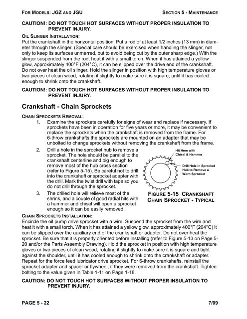
2. Drill a hole in the sprocket hub to remove a<br />
sprocket. The hole should be parallel to the<br />
crankshaft centerline and big enough to<br />
remove most of the hub cross section<br />
(refer to Figure 5-15). Be careful not to drill<br />
into the crankshaft or sprocket adapter with<br />
the drill. Mark the twist drill with tape so you<br />
do not drill through the sprocket.<br />
3. The drilled hole will relieve most of the<br />
shrink, and a couple of good radial hits with<br />
a hammer and chisel will open a sprocket<br />
enough so it can be easily removed.<br />
Hit Here with<br />
Chisel & Hammer<br />
Drill Hole in Sprocket<br />
Hub to Remove a<br />
Worn Sprocket<br />
FIGURE 5-15 CRANKSHAFT<br />
CHAIN SPROCKET - TYPICAL<br />
CHAIN SPROCKETS INSTALLATION:<br />
Encircle the oil pump drive sprocket with a wire. Suspend the sprocket from the wire and<br />
heat it with a small torch. When it has attained a yellow glow, approximately 400°F (204°C) it<br />
can be slipped over the auxiliary end of the crankshaft or adapter. Do not over heat the<br />
sprocket. Be sure that it is properly oriented before installing (refer to Figure 5-13 on Page 5-<br />
20 and/or the Parts Assembly Drawing). Hold the sprocket in position with high temperature<br />
gloves or two pieces of clean wood, rotating it slightly to make sure it is square and tight<br />
against the shoulder, until it has cooled enough to shrink onto the crankshaft or adapter.<br />
Repeat for the force feed lubricator drive sprocket. For 6-throw crankshafts, reinstall the<br />
sprocket adapter and spacer or flywheel, if they were removed from the crankshaft. Tighten<br />
bolting to the value given in Table 1-11 on Page 1-18.<br />
CAUTION: DO NOT TOUCH HOT SURFACES WITHOUT PROPER INSULATION TO<br />
PREVENT INJURY.<br />
PAGE 5 - 22 7/09


