Heavy Duty Balanced Opposed Compressors - Ariel Corporation
Heavy Duty Balanced Opposed Compressors - Ariel Corporation
Heavy Duty Balanced Opposed Compressors - Ariel Corporation
You also want an ePaper? Increase the reach of your titles
YUMPU automatically turns print PDFs into web optimized ePapers that Google loves.
FOR MODELS: JGZ AND JGU SECTION 5 - MAINTENANCE<br />
9. See Connecting Rod Installation on page 5-6 for bearing shell installation. If<br />
clearance readings are not within tolerance after installing new bearings, contact<br />
your packager or <strong>Ariel</strong> before proceeding.<br />
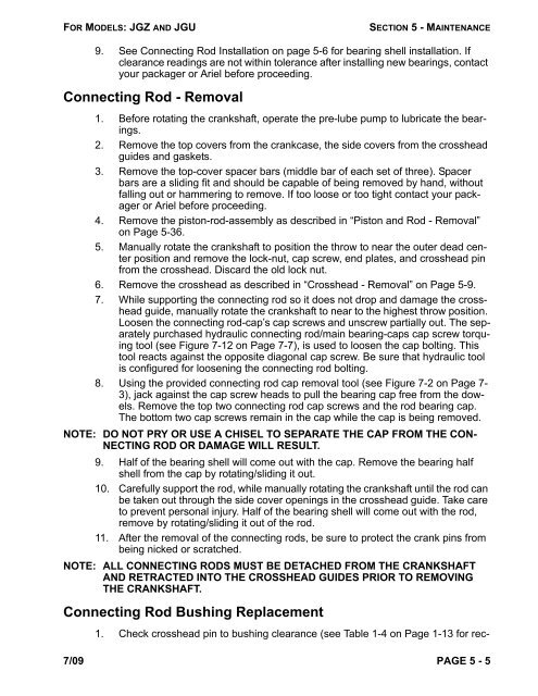
Connecting Rod - Removal<br />
1. Before rotating the crankshaft, operate the pre-lube pump to lubricate the bearings.<br />
2. Remove the top covers from the crankcase, the side covers from the crosshead<br />
guides and gaskets.<br />
3. Remove the top-cover spacer bars (middle bar of each set of three). Spacer<br />
bars are a sliding fit and should be capable of being removed by hand, without<br />
falling out or hammering to remove. If too loose or too tight contact your packager<br />
or <strong>Ariel</strong> before proceeding.<br />
4. Remove the piston-rod-assembly as described in “Piston and Rod - Removal”<br />
on Page 5-36.<br />
5. Manually rotate the crankshaft to position the throw to near the outer dead center<br />
position and remove the lock-nut, cap screw, end plates, and crosshead pin<br />
from the crosshead. Discard the old lock nut.<br />
6. Remove the crosshead as described in “Crosshead - Removal” on Page 5-9.<br />
7. While supporting the connecting rod so it does not drop and damage the crosshead<br />
guide, manually rotate the crankshaft to near to the highest throw position.<br />
Loosen the connecting rod-cap’s cap screws and unscrew partially out. The separately<br />
purchased hydraulic connecting rod/main bearing-caps cap screw torquing<br />
tool (see Figure 7-12 on Page 7-7), is used to loosen the cap bolting. This<br />
tool reacts against the opposite diagonal cap screw. Be sure that hydraulic tool<br />
is configured for loosening the connecting rod bolting.<br />
8. Using the provided connecting rod cap removal tool (see Figure 7-2 on Page 7-<br />
3), jack against the cap screw heads to pull the bearing cap free from the dowels.<br />
Remove the top two connecting rod cap screws and the rod bearing cap.<br />
The bottom two cap screws remain in the cap while the cap is being removed.<br />
NOTE: DO NOT PRY OR USE A CHISEL TO SEPARATE THE CAP FROM THE CON-<br />
NECTING ROD OR DAMAGE WILL RESULT.<br />
9. Half of the bearing shell will come out with the cap. Remove the bearing half<br />
shell from the cap by rotating/sliding it out.<br />
10. Carefully support the rod, while manually rotating the crankshaft until the rod can<br />
be taken out through the side cover openings in the crosshead guide. Take care<br />
to prevent personal injury. Half of the bearing shell will come out with the rod,<br />
remove by rotating/sliding it out of the rod.<br />
11. After the removal of the connecting rods, be sure to protect the crank pins from<br />
being nicked or scratched.<br />
NOTE: ALL CONNECTING RODS MUST BE DETACHED FROM THE CRANKSHAFT<br />
AND RETRACTED INTO THE CROSSHEAD GUIDES PRIOR TO REMOVING<br />
THE CRANKSHAFT.<br />
Connecting Rod Bushing Replacement<br />
1. Check crosshead pin to bushing clearance (see Table 1-4 on Page 1-13 for rec-<br />
7/09 PAGE 5 - 5


