Heavy Duty Balanced Opposed Compressors - Ariel Corporation
Heavy Duty Balanced Opposed Compressors - Ariel Corporation Heavy Duty Balanced Opposed Compressors - Ariel Corporation
FOR MODELS: JGZ AND JGU SECTION 1 - DESIGN SPECIFICATIONS & DATA and new balance nuts or crossheads may be required. The force feed oil distribution system may also need to be resized. TABLE 1-1 APPROXIMATE COMPONENT WEIGHTS COMPONENT POUNDS (KILOGRAMS) Frame Assembly w/o Cylinders See Ariel Electronic Data Book a Main/Connecting Rod Bearing 4 (2) Thrust Plate 12 (5.5) Top Cover, Drive End Section 70 (32) Top Cover, Center Section 140 (63) Top Cover, Auxiliary End Section 85 (37) Top Cover Cross/Spacer Bar 100 (45) Spacer Bar 110 (50) End Cover Drive End 155 (70) Dust Seal Cover 18 (8) End Cover Auxiliary End 265 (120) Lube Oil Pump 130 (50) Crankshaft 2-Throw b 2000 (900) Crankshaft 4-Throw 2 2700 (1225) Crankshaft 6-Throw 2 3600 (1630) Main Journal Caps 85 (39) Connecting Rod 265 (120) Crosshead Guide 1800 (820) Crosshead Guide Gland 35 (15) Crosshead See Balancing Record sheet c for Weights Crosshead Pin 80 (35) Crosshead Guide Large Side Cover 20 (16) Crosshead Guide Small Side Cover 11 (5) VVCP See Ariel Electronic Data Book 1 Cylinder Assembly See Ariel Electronic Data Book 1 Piston & Rod Assembly See Ariel Electronic Data Book 1 a. The Electronic Data Book is available in the Ariel Performance Program. b. Crankshaft weight is without flywheel, vibration or detuner donuts. c. Provided by Ariel in the Parts Book for each compressor. PAGE 1 - 2 7/09
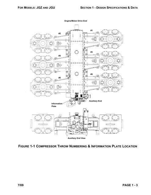
FOR MODELS: JGZ AND JGU SECTION 1 - DESIGN SPECIFICATIONS & DATA #2 #4 #6 Information Plate Engine/Motor Drive End Auxiliary End View FIGURE 1-1 COMPRESSOR THROW NUMBERING & INFORMATION PLATE LOCATION 7/09 PAGE 1 - 3 #1 #3 #5 Auxiliary End
- Page 1 and 2: ARIEL Heavy Duty Balanced Opposed C
- Page 3 and 4: FOR MODELS: JGZ AND JGU TABLE OF CO
- Page 5 and 6: FOR MODELS: JGZ AND JGU TABLE OF CO
- Page 7 and 8: FOR MODELS: JGZ AND JGU TABLE OF CO
- Page 9: FOR MODELS: JGZ AND JGU SECTION 1 -
- Page 13 and 14: FOR MODELS: JGZ AND JGU SECTION 1 -
- Page 15 and 16: FOR MODELS: JGZ AND JGU SECTION 1 -
- Page 17 and 18: FOR MODELS: JGZ AND JGU SECTION 1 -
- Page 19 and 20: FOR MODELS: JGZ AND JGU SECTION 1 -
- Page 21 and 22: FOR MODELS: JGZ AND JGU SECTION 1 -
- Page 23 and 24: FOR MODELS: JGZ AND JGU SECTION 1 -
- Page 25 and 26: FOR MODELS: JGZ AND JGU SECTION 1 -
- Page 27 and 28: FOR MODELS: JGZ AND JGU SECTION 1 -
- Page 29 and 30: FOR MODELS: JGZ AND JGU SECTION 1 -
- Page 31 and 32: FOR MODELS: JGZ AND JGU SECTION 1 -
- Page 33 and 34: FOR MODELS: JGZ AND JGU SECTION 1 -
- Page 35 and 36: FOR MODELS: JGZ AND JGU SECTION 1 -
- Page 37 and 38: FOR MODELS: JGZ AND JGU SECTION 2 -
- Page 39 and 40: FOR MODELS: JGZ AND JGU SECTION 2 -
- Page 41 and 42: FOR MODELS: JGZ AND JGU SECTION 2 -
- Page 43 and 44: FOR MODELS: JGZ AND JGU SECTION 2 -
- Page 45 and 46: FOR MODELS: JGZ AND JGU SECTION 2 -
- Page 47 and 48: FOR MODELS: JGZ AND JGU SECTION 2 -
- Page 49 and 50: FOR MODELS: JGZ AND JGU SECTION 2 -
- Page 51 and 52: FOR MODELS: JGZ AND JGU SECTION 3 -
- Page 53 and 54: FOR MODELS: JGZ AND JGU SECTION 3 -
- Page 55 and 56: FOR MODELS: JGZ AND JGU SECTION 3 -
- Page 57 and 58: FOR MODELS: JGZ AND JGU SECTION 3 -
- Page 59 and 60: FOR MODELS: JGZ AND JGU SECTION 3 -
FOR MODELS: JGZ AND JGU SECTION 1 - DESIGN SPECIFICATIONS & DATA<br />
#2<br />
#4<br />
#6<br />
Information<br />
Plate<br />
Engine/Motor Drive End<br />
Auxiliary End View<br />
FIGURE 1-1 COMPRESSOR THROW NUMBERING & INFORMATION PLATE LOCATION<br />
7/09 PAGE 1 - 3<br />
#1<br />
#3<br />
#5<br />
Auxiliary End


