Dinamap Pro Series Operation Manual - Ardus Medical, Inc.
Dinamap Pro Series Operation Manual - Ardus Medical, Inc.
Dinamap Pro Series Operation Manual - Ardus Medical, Inc.
- No tags were found...

Create successful ePaper yourself
Turn your PDF publications into a flip-book with our unique Google optimized e-Paper software.
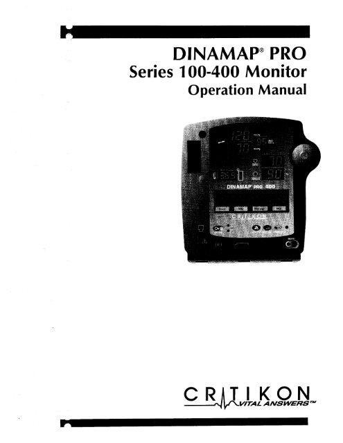
DlNAMAP@ PRO<br />
<strong>Series</strong> 100-400 Monitor<br />
<strong>Operation</strong> <strong>Manual</strong>
Df NAMAP” PRO Monitor<br />
<strong>Operation</strong> <strong>Manual</strong><br />
This manual is for DINAMAP@ PRO Monitor Models 100,<br />
200, 300, and 400, all with printers.<br />
• PRO 100: BP and Pulse<br />
• PRO 200: BP, Pulse, and Temp<br />
• PRO 300: BP, Pulse, and<br />
SpO,<br />
• PRO 400: BP, Pulse, Temp, and<br />
SpO,<br />
The model of the Monitor determines which menu option<br />
buttons appear on the LCD. Please refer to applicable<br />
sections.<br />
Reissues and Updates<br />
Changes occurring between issues are addressed through<br />
Change Information Sheets, Addendums, and replacement<br />
pages. If a Change Information Sheet does not accompany<br />
this manual, it is correct as printed.<br />
Errors and Omissions<br />
If errors or omissions are found in this manual, please<br />
notify:<br />
Critikon<br />
Marketing Services<br />
4502 Woodland Corporate Boulevard<br />
Tampa, FL 33614<br />
1-877-274-8456<br />
Part No. 776995C<br />
The content of this document including all figures and<br />
drawings is proprietary information of Critikon, provided<br />
solely for purposes of operation, maintenance or repair, and<br />
dissemination for other purposes or copying thereof is<br />
prohibited without prior written consent by Critikon, Tampa,<br />
Florida.<br />
Illustrations may show design models; production units may<br />
incorporate changes.
Contents<br />
Introduction .......................................................................... 7<br />
About the DINAMAP@ PRO Monitor.. ................................................................. 7<br />
<strong>Pro</strong>duct Compliance ............................................................................................. 70<br />
Symbols ...................... . .............................................................................................. 11<br />
Getting Started .................................................................... 13<br />
Unpacking the Monitor and Accessories ............ . ........................ . .................... 13<br />
Power Sources .......... . ............................................................................................. 13<br />
Powering t.he Monitor ........................................................................ . ... . ............... 13<br />
Rear Panel Connections. .......................................................................................16<br />
Front Panel Controls and Indicators ................................................................... 17<br />
Switching the Monitor On and Off .................................................................... 19<br />
Liquid Crystal Display (LCD) ............................................................................... 19<br />
Using the Printer .................................................................................................... 20<br />
Installing the Paper ................................................................................................. 20<br />
Printer Alarms........................................................................................................21<br />
Storage ...................................................................................................................... 21<br />
Using the Monitor ............................................................... 23<br />
Noninvasive Blood Pressure Determination ..................................................... 23<br />
<strong>Pro</strong>cedures ................................................................... . ........................................... 27<br />
<strong>Manual</strong> Mode ......................................................................................................... 29<br />
Auto Mode ............................................................................................................... 29<br />
Stat Mode ................................................................................................................. 30<br />
Predictive Temperature Determination ............................................................. 3 1<br />
<strong>Pro</strong>cedures ............................................................................................................... 32<br />
spa* ........ ............. .................... .. ............ ... .. . .. ...... ........ .,..,...,................,.............................................,........................, .......... 34<br />
<strong>Pro</strong>cedures ............................................................................................................... 36<br />
Troubleshooting ..................................................................................................... 39<br />
Using the Menu System ...................................................... 43<br />
Introduction ............................................................................................................. 43<br />
Liquid Crystal Display ............................................................................................ 43<br />
Rotor .... ...................................................................................................................... 46<br />
Menu Tree ................................................................................................................ 46<br />
Main Menu ........................... . .............................................................................. .__ 46<br />
Vitals Button (UK: All Obs) .................................................................................. 47<br />
More ... Button ......................................................................................................... 48<br />
Set BP Button (UK: BP Mode) ................. . ........................................................... 48<br />
Alarms Button ......................................................................................................... 49<br />
Trend Button ............................................................................................................ 51<br />
Print Button .............................................................................................................. 53<br />
More ... Menu ........................................................................................................... 53<br />
SpO2 Button (Models 300 and 400) .................................................................. 54<br />
Config Button ......................................................................................................... 54<br />
Pwr Sav (Sleep Mode) ........................................................................................... 54<br />
Time .......................................................................................................................... 55<br />
Rotor .......................................................................................................................... 56<br />
Display Button ........................................................................................................ 56<br />
Service Button ........................................................................................................ 57<br />
Clinician Menu .......................................................................................................58<br />
Error and Warning Messages .............................................................................. .62<br />
Alarms Button ......................................................................................................... 62<br />
Appendix A .......................................................................... 63<br />
Technical Specifications ..... . .................................................................................. 63
BP. . . . . . . . . . . . . . . . . . . . . . . . . . . . . . . . . . . . . . . . . . . . . . . . . . . . . . . . . . . . . . . . . . . . . . . . . . . . . . . . . . . . . . . . . . . . . . . . . . . . . . . . . . . . . . . . . . . . . . . . . . 63<br />
IVAC Temperature . . . . . . . . . . . . . . . . . . . . . . . . . . . . . . . . . . . . . . . . . . . . . . . . . . . . . . . . . . . . . . . . . . . . . . . . . . . . . . . . . . . . . . . . . . . . . . . . . . 63<br />
SpOz .,.........,.....<br />
..,......._,._,....,..,.,......,,.........<br />
,...... ,. .._ ,....... .._..............__......_....... 64<br />
Mechanical _........... . . . . . . . . . . . . . . . . . . . . . . . . . . . . . . . . . . . . . . . . . . . . . . . . . . . . . . . . . . . . . . . . . . . . . . . . . . . . . . . . . . . . . . . . . . . . . . . . . . 66<br />
Power Requirements . . . . . . . . . . . . . . . . . . . . . . . . . . . . . . . . . . . . . . . . . . . . . . . . . . . . . . . . . . . . . . . . . . . . . . . . . . . . . . . . . . . . . . . . . . . . . 66<br />
Environmental . . . . . . . . . . . . . . . . . . . . . . . . . . . . . . . . . . . . . . . . . . . . . . . . . . . . . . . . . . . . . . . . . . . . . . . . . . . . . . . . . . . . . . . . . . . . . . . . . . . . . . . . .<br />
Appendix B . . . . . . . . . . . . . . . . . . . . . . . . . . . . . . . . . . . . . . . . . . . . . . . . . . . . . . . . . . ..*............. :;<br />
Patient Alarms . . . . . . . . . . . . . . . . . . . . . . . . . . . . . . . . . . . . . . . . . . . . . . . . . . . . . . . . . . . . . . . . . . . . . . . . . . . . . . . . . . . . . . . . . . . . . . . . . . . . . . . . . 69<br />
System Alarms . . . . . . . . . . . . . . . . . . . . . . . . . . . . . . . . . . . . . . . . . . . . . . . . . . . . . . . . . . . . . . . . . . . . . . . . . . . . . . . . . . . . . . . . . . . . . . . . . . . . . . . . 69<br />
Failsafe Alarm _..__...._....,............................................................................................ 69<br />
Hierarchy of Alarms . . . . . . . . . . . . . . . . . . . . . . . . . . . . . . . . . . . . . . . . . . . . . . . . . . . . . . . . . . . . . . . . . . . . . . . . . . . . . . . . . . . . . . . . . . . . . . . 70<br />
Appendix C . . . . . . . . . . . . . . . . . . . . . . . . . . . . . . . . . . . . . . . . . . . . . . . . . . . . . . . . . . . . . . . . . . . . . . . . . . 75<br />
Principles of Noninvasive Blood Pressure Determination . . . . . . . . . . . . . . . . . . . . . . . . . . . . . . 75<br />
Appendix D . . . . . . . . . . . . . . . . . . . . . . . . . . . . . . . . . . . . . . . . . . . . . . . . . . . . . . . . . . . . . . . . . . . . . . . . . . 79<br />
Compatibility Table and Reorder Codes . . . . . . . . . . . . . . . . . . . . . . . . . . . . . . . . . . . . . . . . . . . . . . . . . . . . . . . . . . 79<br />
Appendix E . . . . . . . . . . . . . . . . . . . . . . . . . . . . . . . . . . . . . . . . . . . . . . . . . . . . . . . . . . . . . . . . ..*.*...... 81<br />
Warranty, Service, and Spare Parts . . . . . . . . . . . . . . . . . . . . . . . . . . . . . . . . . . . . . . . . . . . . . . . . . . . . . . . . . . . . . . . . . . . . . 81<br />
Repairs . . . . . . . . . . . . . . . . . . . . . . . . . . . . . . . . . . . . . . . . . . . . . . . . . . . . . . ._.............................................. . . . . . . . . . . . . . . . . . 82<br />
Packing Instructions . . . . . . . . . . . . . . . . . . . . . . . . . . . . . . . . . . . . . . . . . . . . . . . . . . . . . . . . . . . . . . . . . . . . . . . . . . . . . . . . . . . . . . . . . . . . . . . 82<br />
Service <strong>Manual</strong>s . .._............................,....,..................... . . . . . . . . . . . . . . . . . . . . . . . . . . . . . . . . . . . . . . . . . . 82<br />
Appendix F . . . . . . . . . . . . . . . . . . . . . . . . . . . . . . . . . . . . . . . . . . . . . ..*........................... 83<br />
Maintenance . . . . . . . . . . .._..................................... . . . . . . . . . . . . . . . . . . . . . . . . . . . . . . . . . . . . . . . . . . . . . . . . . . . . . . . . . . 83<br />
Cleaning the Monitor . . . . . . . . . . . . . . . . . . . . . . . . . . . . . . . . . . . . . . . . . . . . . . . . . . . . . . . . . . . . . . . . . . . . . . . . . . . . . . . . . . . . . . . . . . . . . 83<br />
Cuff Cleaning and Disinfection . . . . . . . . . . . . . . . . . . . . . . . . . . . . . . . . . . . . . . . . . . . . . . . . . . . . . . . . . . . . . . . . . . . . . . . . . . . . 83<br />
Temperature Devices . . . . . . . . . . . . . . . . . . . . . . . . . . . . . . . . . . . . . . . . . . . . . . . . . . . . . . . . . . . . . . . . . . . . . . . . . . . . . . . . . . . . . . . . . . . . . 84<br />
SpOz Sensors . . . . . . . . . . . . . . . . . . . . . . . . . . . . . . . . . . . . . . . . . . . . . . . . . . . . . . . . . . . . . . . . . . . . . . . . . . . . . . . . . . . . . . . . . . . . . . . . . . . . . . . . . . . 84<br />
Storage and Battery Care . . . . . . . . . . . . . . . . . . . . . . . . . . . . . . . . . . . . . . . . . . . . . . . . . . . . . . . . . . . . . . . . . . . . . . . . . . . . . . . . . . . . . . a5<br />
Fuses . . . . . . . . . . . . . . . . . . . . . . . . . . . . . . . . . . . . . . . . . . . . . . . . . . . . . . . . . . . . . . . . . . . . . . . . . . . . . . . . . . . . . . . . . . . . . . . . . . . . . . . . . . . . . . . . . . . . . . . . . . 86<br />
Calibration . . . . . . . . . . . . . . . . . . . . . . . . . . . . . . . . . . . . . . . . . . . . . . . . . . . . . . . . . . . . . . . . . . . . . . . . . . . . . . . . . . . . . . . . . . . . . . . . . . . . . . . . . . . . . . . . 86<br />
Leak Testing . . .._...._..... . . . . . . . . . . . . . . . . . . . . . . . . . . . . . . . . . . . . . . . . . . . . . . . . . . . . . . . . . . . . . . . . . . . . . . . . . . . . . . . . . . . . . . . . . . . . . . . 86<br />
Disposal of <strong>Pro</strong>duct Waste . . . .._..._....._..............................................~................... 86<br />
Appendix G . . . . . . . . . . . . . . . . . . . . . . . . . . . . . . . . . . . . . . . . . . . . . . . . . . . . . . . . . . . . . . . . . . . . . . . . . . 89<br />
Connection Details . . . . . . . . . . . . . . . . . . . . . . . . . . . . . . . . . . . . . . . . . . . . . . . . . . . . . . . . . . . . . . . . . . . . . . . . . . . . . . . . . . . . . . . . . . . . . . . . . a9<br />
Host Port Connector (rear pane)) . . . . . . . . . . . . . . . . . . . . . . . . . . . . . . . . . . . . . . . . . . . . . . . . . . . . . . . . . . . . . . . . . . . . . . . . 89<br />
.I<br />
,a
About the DINAMAP PRO Monitor<br />
DINAMAP@ PRO Monitors provide noninvasive<br />
determination of systolic blood pressure, diastolic blood<br />
pressure, mean arterial pressure, pulse rate, temperature,<br />
and oxygen saturation. These portable AC- and DCoperated<br />
monitors are primarily intended for use in hospital<br />
acute care settings such as outpatient surgery, accident and<br />
emergency, labor and delivery, Gl/endoscopy, and medical/<br />
surgical units.<br />
The PRO Monitor comes in four different models: PRO 100,<br />
200, 300, and 400, all with printers.<br />
9 PRO 100: BP and Pulse<br />
• PRO 200: BP, Pulse, and Temp<br />
Introduction<br />
. PRO 300: BP, Pulse, and<br />
SpO,<br />
• PRO 400: BP, Pulse, Temp, and<br />
SpO,<br />
All of the main operations of the PRO Monitor are easy to<br />
use. Please review the factory default settings and, where<br />
applicable, enter settings appropriate for your use. The<br />
“Using the Monitor” section of this manual explains how to<br />
use the Monitor in its most simple form, while the “Using<br />
the Menu System” section explains how to customize<br />
measurements by using the menu system.<br />
lndica tions<br />
The PRO Monitor is intended to monitor one patient at the<br />
bedside.<br />
Contraindications<br />
This device is not designed, sold, or intended for use except<br />
as indicated.<br />
Federal law (U.S.A.) restricts this device to sale by or on the<br />
order of a clinician.<br />
. .<br />
Warnings<br />
• Do not use the PRO Monitor in the presence of<br />
magnetic resonance imaging (MRI) devices. There<br />
have been reports of sensors causing patient burns<br />
when operating in an MRI environment.
• Do not use the Monitor in the presence of flammable<br />
anesthetics.<br />
• To help prevent unintended current return paths with<br />
the use of high frequency (HF) surgical equipment,<br />
ensure that the HF surgical neutral electrode is<br />
properly connected.<br />
• To avoid personal injury, do not perform any servicing<br />
unless qualified to do so.<br />
• WARNING: These Monitors should not be used on<br />
patients who are connected to cardiopulmonary<br />
bypass machines.<br />
. If powering the Monitor from an external power<br />
adapter or converter, use only Critikon-approved<br />
power adapters and converters.<br />
• The Monitor does not include any user-replaceable<br />
fuses. Refer servicing to qualified service personnel.<br />
• To reduce the risk of electric shock, do not remove the<br />
cover or the back. Refer servicing to a qualified<br />
service person.<br />
• If the accuracy of any determination reading is<br />
questionable, first check the patient’s vital signs by<br />
alternate means and then check the PRO Monitor for<br />
proper functioning.<br />
Cautions<br />
• Do not use replacement batteries other than the type<br />
supplied with the Monitor. Replacement batteries are<br />
available from Critikon. See Appendix D.<br />
• The PRO Monitor is designed to conform to<br />
Electromagnetic Compatibility (EMC) standard IEC<br />
601-l -2, 1993 and will operate accurately in<br />
conjunction with other medical equipment which also<br />
meets this requirement. To avoid interference<br />
problems affecting the Monitor, do not use the<br />
Monitor in the presence of equipment which does not<br />
conform to these specifications.<br />
8-
Introduction<br />
Place the PRO Monitor on a rigid, secure surface.<br />
Monitor must only be used with mounting hardware,<br />
poles, and stands recommended by Critikon. See<br />
Appendix D.<br />
The weight of the accessory basket contents should<br />
not exceed 6.6 lb (3 kg).<br />
Arrange the power cord, air hoses, and all cables<br />
carefully so they do not constitute a hazard.<br />
Verify calibration of BP parameter (temp and pulse<br />
oximeter do not require calibration). Ensure that the<br />
display is functioning properly before operating the<br />
PRO Monitor.<br />
Do not immerse the Monitor in water. If the Monitor<br />
is splashed with water or becomes wet, wipe it<br />
immediately with a dry cloth.<br />
Do not gas sterilize or autoclave.<br />
The PRO Monitor, when used with Critikon-approved<br />
applied parts and accessories, is protected against<br />
defibrillator damage.<br />
Notes<br />
• Waveforms may be distorted and readings inaccurate<br />
when electrosurgical cautery equipment is used while<br />
monitoring with the PRO Monitor.<br />
- The electromagnetic compatibility profile of the PRO<br />
Monitor may change if accessories other than those<br />
specified for use with the PRO Monitor are used.<br />
• Trend data are retained in the PRO Monitor when it is<br />
turned off, except when the default is overridden by<br />
selecting the Trend button under the Service menu.
<strong>Pro</strong>duct Compliance<br />
The DINAMAP@ PRO Monitor is classified in the following<br />
categories for compliance with IEC 601-l :<br />
• Class<br />
• Transportable<br />
I, internally powered<br />
• For continuous operation<br />
• Not suitable for use in the presence of flammable<br />
anesthetics<br />
• Not for use in the presence of an oxygen-enriched<br />
atmosphere (oxygen tent)<br />
• Type BF applied parts<br />
• IPXl, degree of protection against ingress of water<br />
• Sterilization/Disinfection, see Appendix F<br />
@<br />
C<br />
QD<br />
us<br />
DINAMAP@ PRO MONITOR<br />
CLASSIFIED WITH RESPECT TO ELECTRIC SHOCK, FIRE<br />
AND MECHANICAL AND OTHER SPECIFIED HAZARDS<br />
ONLY IN ACCORDANCE WITH CAN/CSA C22.2 NO.<br />
601 .l . ALSO EVALUATED TO IEC-601-2-30.<br />
CC<br />
0086<br />
This product conforms with the essential requirements<br />
of the <strong>Medical</strong> Device Directive. Accessories without<br />
the CE mark are not guaranteed to meet the Essential<br />
Requirements of the <strong>Medical</strong> Device Directive.<br />
10
Getting Started<br />
Unpacking the Monitor and Accessories<br />
Before attempting to use the PRO Monitor, take a few<br />
minutes to become acquainted with the Monitor and its<br />
accessories. Unpack the items carefully, and check them<br />
against the contents checklist enclosed in one of the<br />
accessory boxes. This is also a good time to check for any<br />
damage or shortage. If there is a problem or shortage,<br />
contact Critikon.<br />
It is recommended that all the packaging be retained, in<br />
case the Monitor must be returned for service in the future.<br />
Power Sources<br />
The PRO Monitor is designed to operate from either an<br />
internal lead-acid battery, AC mains or an IEC 601-l<br />
compliant DC power source (see Appendix A). For<br />
replacement rechargeable batteries, please refer to the<br />
Service section of this manual.<br />
The Monitor contains five fuses. Two AC line input fuses<br />
are mounted internally and are replaceable only by qualified<br />
service personnel. The remaining three fuses are autoresetable<br />
and mounted within the Monitor. These fuses<br />
protect the low voltage DC input, the battery, and the +5 V<br />
output on the host port connector.<br />
Powering the Monitor<br />
Before the PRO Monitor is used for the first time, the<br />
battery should be charged in the Monitor for at least 8<br />
hours.<br />
Refer to the illustration of the rear panel connections.<br />
Looking at the rear of the PRO Monitor, remove the battery<br />
compartment cover. Insert the rechargeable battery into the<br />
compartment so that the battery terminals fit into the power<br />
clips at the bottom of the compartment. Then replace the<br />
cover. Insert the power cord plug into the mains external<br />
power socket (2) and plug into an AC outlet.<br />
Refer to the illustration of the front panel controls and<br />
indicators. With mains or externat DC power connected,<br />
the green external power indicator LED (14) will light to<br />
indicate that external power is being applied and that the<br />
battery is charging. If the battery is not inserted, the external
power indicator LED will flash (short flash approx. every 4 set).<br />
When the Monitor is running on battery power, a battery icon<br />
appears in LCD area 3 (toggling with the time indicator)<br />
indicating the charge status.<br />
.,:<br />
During battery-only operation, the yellow battery power<br />
indicator LED (17) will light. When the battery becomes<br />
discharged beyond the low battery threshold, the indicator will<br />
begin to flash, and the Monitor will sound warning beeps<br />
every 30 seconds. At this point, the Monitor should be<br />
connected to an AC outlet to recharge the battery. If the<br />
Monitor continues to be used without charging the battery,<br />
the message WARNING: THE BAlTERY IS TOO LOW FOR<br />
MONITOR TO FUNCTION. TURN MONITOR OFF appears.<br />
The Monitor shuts down all functions until it is turned off and<br />
the battery is recharged or replaced. To run the Monitor on<br />
AC power, it must be powered off and then on again.<br />
Battery charging will take place as long as the Monitor remains<br />
connected to an external AC power source. A battery that is<br />
fully discharged can be fully recharged in 1 hour 50 minutes<br />
when the Monitor is switched off or 8 hours if the Monitor is<br />
switched on.<br />
Notes<br />
• To prolong the life of the battery, keep the Monitor<br />
connected to an AC outlet whenever possible. NEVER<br />
allow the battery to become completely discharged. A<br />
fully charged battery will power the Monitor for<br />
approximately 2 hours and should survive between 200<br />
and 500 charge/discharge cycles. When it is necessary to<br />
replace the battery, refer to the “Compatibility Table and<br />
Reorder Codes” listed in Appendix D. To ensure full<br />
charge cycles, replace only with a recommended battery.<br />
If the Monitor is to be stored for some time, first charge<br />
the battery and then remove it and store it separately from<br />
the Monitor.<br />
9 For continued safety, use only a power cord of listed type<br />
SJT, three-conductor, min. No. 18 AWG, terminated in a<br />
medical/hospital grade attachment plug, provided with<br />
the following cord tag: “Hospital Grade Plug.” Grounding<br />
14
Getting Started<br />
integrity can only be maintained when equipment is<br />
connected to an equivalent receptacle marked “Hospital<br />
Grade.”<br />
• Where the integrity of the external earth conductor in the<br />
installation or its arrangement is in doubt, the Monitor<br />
be operated from its internal battery.<br />
must<br />
General Caution<br />
Do not touch either the pin of the DC input connector (3)<br />
or the terminals within the battery compartment (1) and<br />
the patient at the same time.<br />
15
**a<br />
• ***e<br />
.:::::t:.<br />
a**me*oe<br />
• :gg::gp<br />
53’<br />
Rear Panel Connections<br />
1<br />
2<br />
3<br />
4<br />
5<br />
6<br />
Battery compartment cover: Retains and protects<br />
internal battery<br />
Mains input: Used to connect to AC power supply<br />
External power socket: To be used with approved<br />
Critikon AC-DC power converter ONLY<br />
Inactive temperature cable storage: Inactive temperature<br />
probe cable attaches here (Models 200 and 400)<br />
Pole clamp: Used to clamp monitor to pole or stand<br />
Data interface connector: Host communications port<br />
(15 way D-type RS-232 serial port) for use only with<br />
equipment conforming to IEC 601-1, configured to<br />
comply with IEC 601-l-l<br />
16
Getting Started<br />
I<br />
15<br />
16 I<br />
17<br />
18<br />
Front Panel Controls and Indicators<br />
7 Systolic pressure display: 3-digit red LED indicates<br />
measured systolic BP in mmHg<br />
8 Active temperature probe holster: Temperature probe<br />
that is being used stored here (Models 200 and 400)<br />
9 Diastolic pressure display: 3-digit red LED indicates<br />
measured diastolic BP in mmHg<br />
10 Temperature probe cover storage: Box of probe covers<br />
stored here (Models 200 and 400)<br />
11 Inactive temperature probe holster: Extra temperature<br />
probe can be stored here (Models 200 and 400)<br />
12 Temperature display: 4-digit red LED indicates measured<br />
temperature (Models 200 and 400)<br />
13 “C “F display: Indicates whether temperature is being<br />
displayed in degrees Celsius or Fahrenheit (Models 200<br />
and 400)
14 External power indicator: Green LED indicates external<br />
power status and battery charging status of monitor<br />
15 Temperature probe connector: Temperature probe cable<br />
attaches here (Models 200 and 400)<br />
16 ON/OFF switch: Controls on/off state of monitor; push<br />
for power on and push again for power off<br />
17 Battery power indicator: Yellow LED indicates operation<br />
and charge status of internal battery<br />
18 SpOz sensor connector: SpOz sensor extension cable<br />
attaches here (Models 300 and 400)<br />
19 Mean arterial pressure display: 3-digit red LED indicates<br />
measured MAP in mmHg and shows instantaneous cuff<br />
pressure during BP determination<br />
20 SpOz pulse indicator: Yellow LED in heart symbol flashes<br />
to indicate that real-time pulse rate measurements are<br />
being derived from SpOz signals (Models 300 and 400)<br />
21 Rotor: Used to highlight and select items in LCD<br />
menus; if monitor is off, pressing rotor will switch<br />
monitor on<br />
22 Pulse BPM display: 3-digit yellow LED shows pulse rate<br />
in beats per minute<br />
23 SpOz display: 3-digit red LED indicates oxygen saturation<br />
in % (Models 300 and 400)<br />
24 SpOz artifact indicator LED: Illuminates when motion<br />
artifact is detected (Models 300 and 400)<br />
25 LCD (liquid crystal display): Displays all alarms, user<br />
interface messages, and configuration options<br />
26 Alarm silence switch: Alternately mutes and enables<br />
audible alarms; when pushed once after alarm sounds<br />
(silence on), switch lights to indicate that audible alarms<br />
have been silenced for 2 minutes<br />
27 AUTO BP key: Press to start Auto BP mode<br />
28 Light sensor: Automatically measures ambient light to set<br />
LED display intensity<br />
29 START/STOP BP key: Press to start or stop a BP, Auto,<br />
Stat, or Vitals determination<br />
30 Cuff connector: BP cuff hose attaches here<br />
18<br />
-<br />
.s>
Getting Started<br />
Switching the Monitor On and Off<br />
@<br />
To switch the DINAMAP PRO Monitor on, push the<br />
ON/OFF switch (16) or press the rotor (21).<br />
power<br />
As the Monitor powers up, it will run a short self-test<br />
routine, which will flash all the indicator lights and then<br />
beep the warning speaker. After a few seconds the system<br />
will be ready for operation, as indicated by the appearance<br />
of the main menu on the LCD (25).<br />
To switch the Monitor off, push the power ON/OFF switch<br />
(16) again. This will terminate any measurements that may<br />
be in progress and automatically deflate the cuff.<br />
When the Monitor is operating on the internal battery only,<br />
battery life is enhanced by the use of the sleep mode.<br />
However, the PRO Monitor will not enter sleep mode if an<br />
alarm is active. If no controls are used and no<br />
determinations are being made, the Monitor will enter sleep<br />
mode after a time which can be preset by the operator. All<br />
LED displays will be blanked except for a dash in the far-left<br />
systolic position, and any existing readings will be<br />
transferred to the LCD, which displays the message “Sleep<br />
Mode Active.” Moving the rotor or pressing a key will<br />
“wake up” the Monitor.<br />
liquid Crystal Display (LCD)<br />
MENU AREA<br />
Menu Area<br />
This area displays the name of the menu that has option<br />
buttons available for selection. Normal text in the menu<br />
area appears dark on a light background, while the text of
selected buttons appears light on a dark background.<br />
Note: Some menus have six option buttons. In these cases, there<br />
is no space available to display the menu title.<br />
Area 2<br />
This area displays<br />
• Source 1:<br />
. Source 2: Last three BP readings<br />
data from one of three different sources.<br />
SpO, plethysmograph (Models 300 and 400)<br />
. Source 3: Error and warning messages<br />
Note: Refer to “Display Button” in the “Using the Menu<br />
System” section for instructions on setting Area 2.<br />
Area 3<br />
This area displays the time, the time lapsed since the last Auto<br />
BP determination (if in Auto BP mode), the battery icon (if<br />
operating on battery power, the time and battery icon toggle),<br />
and the BP and Printer modes.<br />
Using the Printer<br />
Installing the Paper<br />
Turn the PRO Monitor so that the side is facing you. While<br />
grasping the side of the Monitor, firmly press the notched<br />
indentations on the printer door to open it. The printer door will<br />
pop open. With the Monitor powered on, place the roll of paper<br />
into the compartment so that the end of the paper comes off<br />
the top, and thread it between the two printer plates. As the<br />
paper touches the plates, the paper will begin to auto-feed itself<br />
into the printer. Feeding the end of the paper strip through the<br />
slot in the door, firmly press the notched indentation on the side<br />
of the printer door to close it. Use the paper release lever to clear<br />
a paper jam or manually feed the paper.<br />
Note: Make sure that the roll of paper is tightly wound.<br />
_
Any time the paper is loaded, the printer automatically prints a<br />
test strip with the DINAMAP@ PRO name on it. If no print is<br />
visible on the paper, check that the paper roll has been<br />
installed in the correct position (refer to diagram). To tear off<br />
the printout, use a slight sideways action to pull the paper<br />
sharply up across the serrated edge of the door.<br />
Printer Alarms<br />
If the Monitor is<br />
the printer door<br />
Getting Started<br />
switched on with no paper installed or with<br />
open, the message “No Paper” will appear<br />
next to “PRNT” in Area 3 of the LCD. When new paper is<br />
installed and the printer door is closed, the message will<br />
change to “<strong>Manual</strong>” for <strong>Manual</strong> print or “Auto” for Auto print,<br />
depending on the status before the paper change.<br />
If the paper runs out during a print request or if an attempt is<br />
made to print when no paper is installed, the message “Printer<br />
No Paper” will appear in Area 2 of the LCD and an audible<br />
alarm will sound. In addition, the message “No Paper” will<br />
appear next to “PRNT” in Area 3 of the LCD. To clear the<br />
alarm, press the rotor. The message in Area 3 of the LCD will<br />
remain until new paper is installed and the printer door is<br />
closed. (See “Using the Menu System.“)<br />
-<br />
Installing new paper will cause the Critikon DINAMAP PRO<br />
header to be printed, thereby confirming that the paper is<br />
installed correctly and that the printer is operational. The message<br />
next to “PRNT” in Area 3 of the LCD will change to “Auto” or<br />
“<strong>Manual</strong>” to identify the operating mode of the printer. After<br />
power-off, the operating mode of the printer returns to the<br />
previous user-selected setting (Auto or <strong>Manual</strong>) unless specified<br />
otherwise in the Print button under the Service Button.<br />
Storage<br />
Store thermal paper in a cool, dry place. The printed strip<br />
(thermal paper recording) should not be<br />
exposed<br />
to direct sunlight,<br />
. exposed to temperatures over 100<br />
humidity over 80%, or<br />
OF/38 “C or relative<br />
. placed in contact with adhesives, adhesive tapes, or<br />
plasticizers such as those found in all PVC page protectors.
Note: When in doubt about long-term storage conditions, store a<br />
photocopy of the thermal paper recording.<br />
i<br />
Ca &ions<br />
• The paper is thermally activated; therefore, do not store it in a<br />
hot place as discoloration may result.<br />
• Use only replacement paper rolls (58 mm) from Critikon.<br />
22
Using the Monitor<br />
Noninvasive Blood Pressure Determination<br />
Description<br />
The BP parameter is included in Models 100, 200, 300, and<br />
400. Blood pressure is monitored noninvasively in the<br />
PRO Monitor by the oscillometric method, which measures<br />
the amplitude of the pressure oscillations within the blood<br />
pressure cuff. Further information about the oscillometric<br />
method is in Appendix C.<br />
The PRO Monitor has four BP modes: 1. <strong>Manual</strong>,<br />
2. Auto, 3. Stat, and 4. Vitals (UK: All Obs). The mode,<br />
which is selected by the user, is shown on the LCD (25).<br />
The BP measurements are automatic, and once the cycle is<br />
complete the LED displays (7, 9, 19, 22) show systolic<br />
pressure, diastolic pressure, mean arterial pressure, and<br />
pulse rate.<br />
1.<br />
<strong>Manual</strong> BP determinations are started by pressing the<br />
START/STOP BP key (29). In the <strong>Manual</strong> mode, the<br />
blood pressure is determined one time.<br />
2.<br />
Auto BP determinations are started by selecting the<br />
AUTO BP key (27) or the Auto button under the Set<br />
(UK: BP Mode) button in the Main menu.<br />
BP<br />
When Auto mode is selected, a number at the right of<br />
the Auto button indicates the time interval between each<br />
reading. To change the time interval, choose the box<br />
around the number and turn the rotor until the desired<br />
interval is reached. The interval can be set between 1<br />
and 120 minutes (1, 2, 3, 4, 5, 10, 15, 20, 25, 30, 45, 60,<br />
90, and 120 minutes). Press the rotor to confirm the<br />
setting.<br />
3.<br />
4.<br />
Stat determinations are started by selecting the Stat<br />
button under the Set BP button (UK: BP Mode) in the<br />
Main menu. In the Stat mode, the blood pressure is<br />
determined as many times as possible in 5 minutes.<br />
Vitals (UK: All Obs) determinations are started by<br />
selecting the Vitals (UK: All Obs) button in the Main<br />
menu. (Refer to the “Using the Menu System” section.)<br />
Selection of this button initiates a BP determination<br />
-%<br />
” F<br />
23<br />
h
while allowing SpOz and predictive temperature<br />
determinations to be monitored and recorded<br />
(depending on Monitor model). In the Vitals (UK: All<br />
Obs) mode, the blood pressure is determined one time.<br />
Before each BP determination, the Monitor performs a test<br />
to ensure that the cuff pressure is below a specified level.<br />
The determination is delayed until this condition is met.<br />
During the delay, the BP values are displayed as zero.<br />
The Monitor senses the type of hose being used and<br />
automatically uses adult/pediatric monitoring parameters or<br />
neonatal monitoring parameters, as appropriate.<br />
Audible and visible alarms occur when a value for systolic<br />
pressure, diastolic pressure, mean arterial pressure, or pulse<br />
rate is outside the selected high or low limit.<br />
Instructions for cleaning and disinfecting BP cuffs are in<br />
Appendix F.<br />
Genera/ Warnings<br />
• The PRO Monitor will not measure blood pressure<br />
effectively on patients who are experiencing seizures<br />
or tremors.<br />
• Arrhythmias will increase the time required by the<br />
PRO Monitor to determine a blood pressure and may<br />
extend the time beyond the capabilities of the<br />
Monitor.<br />
• In <strong>Manual</strong> mode, the PRO Monitor displays the results<br />
of the last blood pressure determination for 2 minutes<br />
or until another determination is completed. If a<br />
patient’s condition changes between one<br />
determination and the next, the Monitor will not<br />
detect the change or indicate an alarm condition.<br />
• Devices that exert pressure on tissue have been<br />
associated with purpura, skin avulsion, compartmental<br />
syndrome, ischemia and/or neuropathy. To minimize<br />
these potential problems, especially when monitoring<br />
at frequent intervals or over extended periods of time,<br />
make sure the cuff is applied appropriately and<br />
-24
Using<br />
the Monitor<br />
the limb distal to the cuff<br />
examine the cuff site and<br />
regularly for signs of impeded blood flow.<br />
. Do not apply external pressure against cuff while<br />
monitoring. Doing so may cause inaccurate blood<br />
pressure values.<br />
• Use care when placing cuff on extremity used to<br />
monitor other patient parameters.<br />
dual-<br />
• The PRO Monitor is designed for use only with<br />
tube cuffs.<br />
. Accuracy of BP measurement depends on using a cuff<br />
of the proper size. It is essential to measure the<br />
circumference of the limb and to select the proper<br />
size cuff. The air hoses are color-coded according to<br />
size of the patient. The gray 12- or 24-foot hose (3.66<br />
m or 7.3 m) is required on patients who require cuff<br />
sizes from infant through thigh cuffs. The teal (bluegreen)<br />
12-foot hose (3.66 m) is required for the<br />
neonatal cuff sizes #l through #5.<br />
• Use only accessories recommended by Critikon.<br />
Failure to use recommended accessories may result in<br />
inaccurate readings. See Appendix D.<br />
• Blood pressure cuffs should be removed from the<br />
patient when the Monitor is powered off. If the<br />
extremity remains cuffed under these conditions or if<br />
the interval between blood pressure determinations is<br />
prolonged, the patient’s limb should be observed<br />
frequently and the cuff placement site should be<br />
rotated as needed.<br />
General Cautions<br />
.<br />
.<br />
If it becomes necessary to move the cuff to another<br />
limb, make sure the appropriate size cuff is used.<br />
The pulse rate derived from a BP determination may<br />
differ from the heart rate derived from an EKG<br />
waveform because the PRO Monitor measures actual<br />
peripheral pulses, not electrical signals or<br />
contractions from the heart. Differences may occur<br />
because electrical signals at the heart occasionally fail
to produce a peripheral pulse or the patient may have<br />
poor peripheral perfusion. Also, if a patient’s beat-tobeat<br />
pulse amplitude varies significantly (e.g., because<br />
of pulsus alternans, atrial fibrillation, or the use of a<br />
rapid-cycling artificial ventilator), blood pressure and<br />
pulse rate readings can be erratic, and an alternate<br />
measuring method should be used for confirmation.<br />
General Notes<br />
• A patient’s vital signs may vary dramatically during the<br />
use of cardiovascular agents such as those that raise or<br />
lower blood pressure or those that increase or decrease<br />
heart rate.<br />
9 Because treatment protocols based on the patient’s<br />
blood pressure may rely on specific values and differing<br />
measurement methods, such as auscultatory, clinicians<br />
should note a possible variance from values obtained<br />
with the PRO Monitor in planning patient care<br />
management. The PRO Monitor values are based on<br />
the oscillometric method of noninvasive blood pressure<br />
measurement and correspond to comparisons with<br />
inn-a-aortic values within ANSI /AAMI Standards for<br />
accuracy (a mean difference of + 5 mmHg, and a<br />
standard deviation of + 8 mmHg).<br />
. Several conditions may cause the BP parameter to<br />
calculate and display only the mean arterial pressure<br />
(MAP) without a systolic and diastolic reading. These<br />
conditions include very low systolic and amplitude<br />
fluctuations, so an accurate calculation for these values<br />
can’t be made (e.g., patient in shock); too small of a<br />
difference between systolic and MAP calculations in<br />
relationship to the difference between diastolic and<br />
MAP; or a leak has occurred in the PRO Monitor<br />
(1. Check all BP connections 2. Monitor may need<br />
calibration and leak testing). If only the MAP value is<br />
displayed, the systolic and diastolic will display dashes<br />
(-) and an alarm message “N99-BP FAILED” will be<br />
displayed.<br />
26
Using the Monitor<br />
<strong>Pro</strong>cedures<br />
1. Connect the end of the air hose which has quick-release<br />
clips to the cuff connector (30) on the front of the Monitor.<br />
Make sure that the hose is not kinked or compressed.<br />
Note: To disconnect the hose from the Monitor, squeeze<br />
the quick-release clips together and pull the plug from the<br />
cuff connector (30).<br />
2. Select the appropriate blood pressure measurement site.<br />
Because normative values are generally based on this site<br />
and as a matter of convenience, the upper arm is preferred.<br />
When upper arm size or shape, the patient’s clinical<br />
condition, or other factors prohibit use of the upper arm,<br />
the clinician must plan patient care accordingly, taking into<br />
account the patient’s cardiovascular status and the effect of<br />
an alternative site on blood pressure values, proper cuff<br />
size, and comfort. The figure shows the recommended sites<br />
for placing cuffs.<br />
Warning: Do not place the cuff on a limb being used<br />
for intravenous infusion or any area where circulation<br />
is compromised or has the potential to be compromised.<br />
I<br />
f<br />
Adult/Pediatric<br />
Neonate<br />
3.<br />
4.<br />
If patient is standing, sitting, or inclined, ensure that cuffed<br />
limb is supported to maintain cuff at level of patient’s<br />
heart. If cuff is not at heart level, the difference in systolic<br />
and diastolic values due to hydrostatic effect must be<br />
considered. Add 1.80 mmHg to values for every inch (2.54<br />
cm) above heart level. Subtract 1.80 mmHg from values for<br />
every inch (2.54 cm) below heart level.<br />
Select appropriate cuff size. Measure patient’s limb and<br />
select appropriately sized cuff according to size marked on<br />
cuff or cuff packaging. When cuff sizes overlap for a<br />
specified circumference, choose the larger size cuff.<br />
Precaution: Accuracy depends on use of proper size cuff.
5. Inspect cuff for damage. Replace cuff when aging,<br />
tearing, or weak closure is apparent. Do not inflate<br />
cuff when unwrapped.<br />
Precaution: Do not use cuff if structural integrity is<br />
suspect.<br />
6. Connect the cuff to the air hose. Thread the cuff<br />
connectors onto the hose connectors until finger tight.<br />
Do not overtighten.<br />
Warning: It is mandatory that the appropriate hose and<br />
cuff combination be used. Any attempt to modify the<br />
hose will inhibit the Monitor from switching between<br />
the neonatal and adult measurement modes.<br />
Note: In normal use, each cuff will have its own hose, so<br />
it will not usually be necessary to disconnect them. If it is<br />
necessary to do so, carefully unscrew the cuff from the<br />
hose. Care should be taken in reconnecting the cuff to a<br />
hose, ensuring that threads of the cuff and hose are in<br />
alignment and no cross-threading occurs.<br />
7. Inspect patient’s limb prior to application.<br />
Precaution: Do not apply cuff to areas where skin is not<br />
intact or tissue is injured.<br />
8. Palpate artery and place cuff so that patient’s artery is<br />
aligned with cuff arrow marked “artery.”<br />
9. Squeeze all air from cuff and confirm that connection is<br />
secure and unoccluded and that tubing is not kinked.<br />
1 O.Wrap cuff snugly around the patient’s limb. Cuff index<br />
line must fall within the range markings. Ensure that hook<br />
and loop closures are properly engaged so that pressure<br />
is evenly distributed throughout cuff. If upper arm is<br />
used, place cuff as far proximally as possible.<br />
11 .<strong>Pro</strong>per cuff wrapping should be snug, but should still<br />
allow space for a finger between patient and cuff. Cuff<br />
should not be so tight as to prevent venous return<br />
between determinations.<br />
Warning: Using a cuff that is too tight will cause<br />
venous congestion and discoloration of the limb, but<br />
using a cuff that is too loose may result in no readings<br />
and/or inaccurate readings.<br />
12.<strong>Pro</strong>ceed with monitoring in the <strong>Manual</strong>, Auto, Stat, or<br />
Vitals (UK: All Obs) mode.<br />
28
<strong>Manual</strong> Mode<br />
Using the Monitor<br />
@<br />
To start a determination, press the START/STOP BP key (29).<br />
A normal, uninterrupted <strong>Manual</strong> cycle takes about 40<br />
seconds. The cuff pressure must drop below 5 mmHg<br />
(neonate) or 15 mmHg (adult) before another<br />
determination can be started. BP information will be<br />
displayed for 2 minutes on the LED unless another<br />
determination is started within that time frame. This applies<br />
to <strong>Manual</strong> and Vitals (UK: All Obs) modes. After power-off,<br />
the operating mode returns to the default setting of <strong>Manual</strong>.<br />
The default setting of <strong>Manual</strong> can be overridden to return to<br />
the previous user-selected setting (Auto or <strong>Manual</strong>) by<br />
selecting Set BP (UK: BP Mode) under the Service menu.<br />
Note: The START/STOP BP key is an on-off switch; pressing<br />
it will stop any BP determination (<strong>Manual</strong>, Auto, Stat, or<br />
Vitals) that is in progress.<br />
Auto Mode<br />
&Z)<br />
Auto BP determinations are started by selecting the AUTO<br />
BP key (27) or the Auto button under the Set BP button<br />
(UK: BP Mode) in the Main menu.<br />
Selecting the AUTO BP key (27) brings up the Set BP menu<br />
(UK: BP Mode) and automatically starts an Auto BP<br />
determination as long as the Monitor is in <strong>Manual</strong> BP mode.<br />
If the Monitor is already in Auto BP mode, selection of the<br />
AUTO BP key (27) brings up the Set BP menu (UK: BP<br />
Mode) without starting a new determination until the preset<br />
time interval has expired. Pressing the START/STOP BP key<br />
during a series of Auto BP determinations will cancel the<br />
determination in progress.<br />
When Auto mode is selected, a number at the right of the<br />
Auto button indicates the time interval between each<br />
reading. To change the time interval, choose the box around<br />
the number and turn the rotor until the desired interval is<br />
reached. The interval can be set between 1 and 120<br />
minutes (1, 2, 3, 4, 5, 10, 15, 20, 25, 30, 45, 60, 90, and<br />
29
120 minutes). Press the rotor to confirm the setting. After<br />
power-off, the operating mode returns to the default setting<br />
of <strong>Manual</strong>. The default setting of <strong>Manual</strong> can be overridden<br />
to return to the previous user-selected setting (Auto or<br />
<strong>Manual</strong>) by selecting Set BP (UK: BP Mode) under the<br />
Service menu.<br />
In the Auto mode, the pressure must be below 5 mmHg<br />
(neonate) or 15 mmHg (adult) for at least 30 seconds<br />
before another determination can be started. BP<br />
information will be displayed on the LED until the next<br />
determination is started. This applies to Auto mode only.<br />
Note: To cancel an Auto BP determination, select the<br />
<strong>Manual</strong> button in the Set BP menu (UK: BP Mode).<br />
Stat Mode<br />
Multiple BP readings can be taken at any time by selecting<br />
the Stat button under the Set BP button (UK: BP Mode) in<br />
the Main menu. Stat mode can also be accessed by<br />
pressing the AUTO BP key (27) and then selecting the Stat<br />
button when the Set BP menu (UK: BP Mode) appears.<br />
If a <strong>Manual</strong> determination is not in progress, a S-minute<br />
series of determinations will start. If a <strong>Manual</strong> determination<br />
is in progress, that determination will become the first in the<br />
series. A normal, uninterrupted Stat sequence will give the<br />
first set of systolic, diastolic, and mean arterial pressure<br />
values and pulse rate within 15 to 20 seconds. Selecting the<br />
Stat button during a series of Stat determinations will cancel<br />
the determination in progress and the rest of the series. BP<br />
information will be displayed on the LED until the<br />
determination has been canceled or completed. This applies<br />
to Stat mode only.<br />
The series begins with cuff inflation to a pressure above the<br />
previous systolic pressure or, if no previous systolic value is<br />
stored, to approximately 160 mmHg for adult/pediatrics.<br />
The initial target pressure selection for neonates is 110<br />
mmHg. Artifact rejection is relaxed in the Stat mode for<br />
adult/pediatric patients to allow for accelerated<br />
determinations. If a BP or Stat reading has been made<br />
previously, the first new systolic value will flash on the LED<br />
display (7) within a few seconds and will continue to flash<br />
until the end of the determination. At that point a short tone<br />
will sound and the updated systolic, diastolic, and mean<br />
30 t;
Using the Monitor<br />
arterial pressures and pulse rate will appear on their LED<br />
displays (7, 9, 19, 22). The Monitor will begin another<br />
determination once the pressure is below 5 mmHg for 8<br />
seconds (neonates) or 15 mmHg for 4 seconds (adults),<br />
unless the S-minute period has ended or the determination<br />
has been canceled.<br />
Note: Alarm limits are disabled while in Stat mode.<br />
Predic five Tempera ture De termina tion<br />
Q<br />
Description<br />
The temperature parameter is included in Models 200 and<br />
400. The PRO Monitor uses IVAC* technology and can be<br />
used with both oral and rectal temperature probes. Two<br />
modes of operation are available: predictive and monitor.<br />
In predictive mode, a final temperature is displayed with an<br />
audible tone. In monitor mode, the display is updated<br />
continually as the patient’s temperature rises or falls.<br />
Note: If the PRO is unable to complete a predictive<br />
determination, then it enters monitor mode. These<br />
temperature readings are not stored in trends and not<br />
reported via host comms.<br />
During a temperature determination, the temperature<br />
display (12) provides a progress meter and probe ready<br />
indicator. In the far-left position, a single horizontal line<br />
indicates the probe is ready to start a determination after<br />
removal from the probe holster. In the far-right position of<br />
the temperature display, a “chase sequence” around the<br />
outside space indicates a predictive temperature<br />
determination is in progress. During monitor mode, the<br />
temperature readings flash constantly.<br />
Temperature is shown on the temperature display in<br />
degrees Celsius or Fahrenheit, and the unit of measure is<br />
indicated by the “C “F display (13). The default, which is<br />
Celsius, can be changed in the Clinician Menu (please refer<br />
to the “Using the Menu System” section of this manual).<br />
*IVAC is a trademark of Alaris <strong>Medical</strong> Systems
General Warning<br />
• The performance of the Monitor may be degraded if it<br />
is operated outside of the environmental conditions<br />
specified in Appendix A.<br />
General Cautions<br />
• Be careful not to overextend the coiled cord of the<br />
temperature probe. Overextension can damage the<br />
probe coil connector interfaces.<br />
• Accurate oral temperatures (blue) can only be<br />
obtained by placing the probe under the tongue in the<br />
right or left sublingual pocket. Temperatures in other<br />
locations in the mouth can vary by more than 2 OF or<br />
1 OC.<br />
• Accurate rectal temperatures can only be obtained by<br />
using the red temperature probe. Red and blue<br />
temperature probes are not interchangeable.<br />
• Do not allow the tip of the predictive temperature<br />
probe to come into contact with a heat source (e.g.,<br />
hands or fingers) prior to taking a temperature<br />
determination. If this occurs, allow 5 seconds for the<br />
probe tip to cool before proceeding.<br />
• Use only IVAC* probes and probe covers. The size,<br />
shape, and thermal characteristics of the probe covers<br />
can affect the performance of the instrument.<br />
Inaccurate readings or retention problems may occur<br />
unless IVAC probes and probe covers are used.<br />
<strong>Pro</strong>cedures<br />
1. Connect the temperature probe cable to the<br />
temperature probe connector (15).<br />
2. Remove the temperature probe from the probe holster.<br />
Place a protective temperature probe cover on the<br />
probe and insert the probe appropriately.<br />
3. The determination begins automatically. Hold the<br />
temperature probe steady until the determination is<br />
complete. This takes approximately 60 seconds, during<br />
which time a pattern of lines on the temperature display<br />
(12) appears as a “chase sequence” to indicate progress.<br />
*IVAC is a trademark of Alaris <strong>Medical</strong> Systems<br />
32
4.<br />
Using the Monitor<br />
When the determination is complete, an audible tone<br />
sounds and the temperature appears on the display.<br />
Record the temperature and remove the probe. Discard<br />
the disposable cover by holding the probe as you would<br />
a syringe and pressing the button on the probe handle.<br />
Place the probe in the probe holster. Once you place the<br />
probe in the probe holster, the temperature values will<br />
be cleared.<br />
Notes<br />
• If the probe tip temperature is 94.0” F or higher<br />
(34.4” C) when taken out of the probe holster, the<br />
thermometer will not be able to perform a predictive<br />
measurement. Instead, the thermometer will<br />
automatically go into monitor mode. The temperature<br />
reading will then flash. A correct final temperature<br />
reading may require 3 minutes or longer. Th.e Monitor<br />
will not beep at final temperature. It will continue to<br />
monitor the patient’s temperature until the probe is<br />
removed from the patient and returned to the probe<br />
holster.<br />
• To cool the temperature probe down, wipe with alcohol.<br />
• If there is a long delay from the time the probe is<br />
removed from the probe holster until it is inserted into<br />
the patient’s mouth, it is possible that the instrument will<br />
not display a final temperature. If this occurs, insert the<br />
probe into the probe holster, remove it again, and start a<br />
new measurement.<br />
- If an alarm is actively sounding, an audible tone will not<br />
sound.<br />
• If tissue contact is lost, the chase sequence on the<br />
temperature display (12) stops. If tissue contact is not<br />
made within 1 minute, the Monitor will alarm.
spa,<br />
Description<br />
The SpOz parameter is included in Models 300 and 400. To<br />
begin SpOz monitoring, simply place the SpOZ sensor on<br />
the patient’s finger; monitoring begins automatically.<br />
Functional oxygen saturation (SpOJ of arterial blood is<br />
noninvasively and continuously monitored in the<br />
PRO Monitor using pulse oximetry technology from<br />
NELLCOR*. Functional SpOz is the ratio of oxygenated<br />
hemoglobin to hemoglobin that is capable of transporting<br />
oxygen. This ratio, expressed as a percentage, is shown on<br />
the SpOz display (23), which is continually updated.<br />
Heart rate derived from Sp02 appears in the Pulse BPM<br />
display (22), and the SpOz pulse indicator (20) flashes<br />
synchronization with the real-time pulse rate measurements<br />
that are derived from the SpOz signal. A tone sounds at a<br />
rate corresponding to the pulse rate and at a pitch<br />
corresponding to the SpOZ saturation level. The pitch is<br />
highest at 100% oxygen saturation, and it becomes lower as<br />
the saturation level falls. The Monitor can display a pulse<br />
amplitude bar and a plethysmographic waveform on the<br />
LCD (25). The pulse amplitude bar graph is proportional to<br />
the arterial blood flow. The artifact indicator LED (24) lights<br />
continuously when the Monitor detects motion sufficient<br />
enough to affect readings.<br />
Audible and visible alarms occur when SpOz: levels are<br />
outside the alarm limits. When a limit alarm occurs, a<br />
message appears in Area 2 of the LCD display.<br />
If you select the Alarms button, the Alarms menu appears.<br />
This menu is used to adjust the violation limits for BP and<br />
SpOz. Refer to “Alarms Button” in the “Using the Menu<br />
System” section.<br />
*NELLCOR is a trademark of Mallinckrodt,<br />
34<br />
<strong>Inc</strong>.
Using the Monitor<br />
If you select the Suspend button, the SpOz alarm is suspended<br />
for 2 minutes and then the PRO returns to normal SpOz<br />
monitoring. A message informing the user that Sp02 is<br />
suspending appears in Area 2 and dashes appear in the SpOz<br />
LED while the Sp02 alarm suspend is counting down.<br />
Selecting Cancel will cancel the SpOZ alarm suspension and<br />
return to monitoring Sp02.<br />
Low<br />
SpOz is suspending<br />
2:oo<br />
ICancel<br />
If the Monitor is unable to detect a pulse for 10 seconds<br />
during normal SpOz monitoring, the values in the LED flash,<br />
alternating patient values with dashes. The Monitor returns to<br />
normal SpOz reporting of values when several consecutive<br />
good pulse determinations are made.<br />
Genera/ Warnings<br />
• Do not use the SpOZ function during magnetic<br />
resonance imaging (MRI). Adverse reactions include<br />
potential burns to patients as a result of contact with<br />
attachments heated by the MRI radio frequency pulse,<br />
potential degradation of the magnetic resonance image,<br />
and potential reduced accuracy of SpOZ measurements.<br />
Always remove oximetry devices and attachments from<br />
the MRI environment before scanning a patient.<br />
• The use of cardio-green and other intravascular dyes at<br />
certain concentrations may affect the accuracy of the<br />
SpOZ measurement.<br />
• The SpOZ function is calibrated to read functional<br />
arterial oxygen saturation. Significant levels of<br />
dysfunctional hemoglobins such as carboxyhemoglobin<br />
or methemoglobin may affect the accuracy of the SpOZ<br />
measurement.<br />
General Cautions<br />
• As with any clip-on sensor, pressure is exerted. The<br />
clinician should be cautious in using a clip-on sensor on
patients with compromised circulation (e.g., because of<br />
peripheral vascular disease or vasoconstricting<br />
medications).<br />
• Do not perform any testing or maintenance on a sensor<br />
while it is being used to monitor a patient.<br />
. Bright light sources (e.g., infrared heat lamps, bilirubin<br />
lights, direct sunlight, operating room lights) may interfere<br />
with the performance of the SpOZ function. To prevent<br />
such interference, cover the sensor with opaque material.<br />
_,<br />
>T<br />
I<br />
General Notes<br />
. A patient’s vital signs may vary dramatically during the use of<br />
cardiovascular agents such as those that raise or lower blood<br />
pressure or those that increase or decrease heart rate.<br />
• The PRO Monitor is compatible only with NELLCOR sensors.<br />
• Software development, software validation, and Risk and<br />
Hazard Analysis has been performed to a registered quality<br />
system.<br />
. ,<br />
_,<br />
<strong>Pro</strong>cedures<br />
1. Select a sensor that is appropriate for the patient and the<br />
clinical situation.<br />
Warning: Do not use a damaged sensor or one with<br />
exposed electrical contacts.<br />
Note: Use only NELLCOR sensors, which are available<br />
from:<br />
USA<br />
Mallinckrodt, <strong>Inc</strong>.<br />
675 MacDonnell Blvd<br />
PO Box 5840<br />
St. Louis, MO 63 134<br />
Phone: 1-800-NELLCOR<br />
(USA) Fax: l-888-222-9799<br />
1<br />
UK<br />
Nellcor<br />
10 Talisman Business Center<br />
London Road<br />
Bicester<br />
Oxfordshire 0X6-OJX<br />
UK<br />
Phone: 44-189-632-2700
2<br />
Using the Monitor<br />
Following the directions for use supplied<br />
apply the sensor to the patient.<br />
Warnings<br />
Patient safety:<br />
with the sensor,<br />
If you fail to apply the sensor properly, the patient’s<br />
skin could be injured or the ability of the PRO<br />
Monitor to measure oxygen saturation could be<br />
compromised, For example, a clip-on sensor should<br />
never be taped shut. Taping the sensor could damage<br />
the patient’s skin or impair the venous return, thus<br />
causing venous pulsation and inaccurate<br />
measurement of oxygen saturation.<br />
Excessive pressure from the sensor may cause necrosis<br />
of the skin.<br />
Monitor performance:<br />
When an SpOZ sensor is on a limb that has a blood<br />
pressure cuff, the SpOZ data will not be valid when<br />
the cuff is inflated. If SpOZ readings are required<br />
during the entire blood pressure determination, attach<br />
the SpO, sensor to the limb opposite the one with the<br />
blood pressure cuff.<br />
Remove nail polish and artificial nails. Placing a sensor<br />
on a polished or an artificial nail may affect accuracy.<br />
Cautions<br />
Patient safety:<br />
Do not place any clip-on sensor in a patient’s mouth<br />
or on a patient’s nose or toe.<br />
Do not place a clip-on finger sensor on a patient’s<br />
thumb or across a child’s foot or hand.<br />
Observe the sensor site to assure adequate distal<br />
circulation.<br />
Monitor performance:<br />
• For best performance, place the sensor at heart level.<br />
• Placing a sensor distal to an arterial line may interfere<br />
with adequate arterial pulsation and compromise the<br />
measurement of SpOZ.<br />
37
3.<br />
4.<br />
• Place the sensor so that the<br />
opposite each other.<br />
LEDs and the photodiode are<br />
Plug the SpOz sensor into the Sp02 sensor extension cable.<br />
Then plug the SpOZ sensor extension cable into the SpOz<br />
sensor connector (18).<br />
<strong>Pro</strong>ceed with monitoring. SpOz determinations run<br />
continuously and can run simultaneously with other<br />
measurements.<br />
. . ,<br />
.;<br />
38
• Excessive patient motion may be making<br />
SpOz function to find a pulse pattern.<br />
• The sensor may be damaged.<br />
• The patient’s perfusion may be too low to allow the<br />
function to measure saturation and pulse rate.<br />
SOLUTION:<br />
Check the patient.<br />
• If possible, keep the patient still; check whether the SpOz<br />
sensor is applied securely and properly, and replace it if<br />
necessary; move the sensor to a new site; or use a disposable<br />
adhesive sensor that may tolerate more motion.<br />
• Replace the sensor.<br />
PROBLEM: The SpO2 value or the pulse rate changes rapidly; the<br />
puise amplitude bar is erratic.<br />
CAUSE:<br />
. Excessive patient motion may be making it impossible for the<br />
SpOz function to find a pulse pattern.<br />
• An electrosurgical unit (ESU) may be interfering with<br />
performance.<br />
SOLUTION:<br />
Check the patient.<br />
Using the Monitor<br />
Troubleshooting<br />
This section discusses potential difficulties and suggestions for<br />
resolving them. If the difficulty persists, contact a qualified service<br />
person or your local Critikon representative.<br />
The service manual, which is for use by qualified service personnel<br />
provides additional troubleshooting information.<br />
PROBLEM: The pulse amplitude bar indicates a pulse, but no<br />
oxygen saturation or pulse rate values appear on the screen.<br />
CAUSE:<br />
it impossible for the<br />
SpOz<br />
• If possible, keep the patient still; check whether the sensor is<br />
applied securely and properly, and replace it if necessary;<br />
move the sensor to a new site; use a sensor that tolerates more<br />
motion.<br />
Y-<br />
” i<br />
LI<br />
39
If an ESU is interfering:<br />
• Move the<br />
SpOz cable as far from the<br />
ESU as possible.<br />
• Plug the Monitor and the ESU into different AC circuits.<br />
• Move the ESU ground pad as close to the surgical site as<br />
possible.<br />
0 The sensor may be damp or may need to be replaced with a<br />
new sensor.<br />
• If the patient weighs less than 3 kg or more than 40 kg, apply<br />
an OXISENSOR N-25 oxygen transducer to an appropriate<br />
site. This sensor has added protection against electrosurgical<br />
interference.<br />
PROBLEM: The oxygen saturation measurement does not<br />
correlate with the value calculated from a blood gas<br />
determination.<br />
CAUSE:<br />
• The Sp02 calculation may not have correctly adjusted for the<br />
effects of pH; temperature; CO,; fetal hemoglobin; or 2,3-<br />
DPG.<br />
• Accuracy can be affected by incorrect sensor application or<br />
use; intravascular dyes; bright light; excessive patient<br />
movement; venous pulsations; electrosurgical interference;<br />
and placement of a sensor on an extremity that has a blood<br />
pressure cuff, arterial catheter, or intravascular line.<br />
SOLUTION:<br />
• Check that calculations have been corrected appropriately for<br />
the relevant variable. In general, calculated saturation values<br />
are not as reliable as direct laboratory hemoximeter<br />
measurements.<br />
• If there is excessive light, cover the sensor with opaque<br />
material.<br />
• Circulation distal to the sensor site should be checked<br />
routinely. The site must be inspected every 8 hours to ensure<br />
adhesion, skin integrity, and correct optical alignment. If skin<br />
integrity changes, move the sensor to another site.<br />
40<br />
-
• Try to keep the patient still, or change the sensor site to one with<br />
less motion.<br />
• Observe all instructions, warnings, and cautions in this manual<br />
and in the directions for use of the sensor.<br />
PROBLEM: A valid SpO2 signal was present but has disappeared.<br />
CAUSE:<br />
• A BP determination on the same limb is in progress.<br />
SOLUTION:<br />
• An alarm message (No signal) will appear on the screen, and the<br />
audible alarm will sound immediately.<br />
PROBLEM: A bad signal error has occurred.<br />
CAUSE:<br />
• Weak or “noisy” signal.<br />
SOLUTION:<br />
Check the patient.<br />
. If possible, keep the patient still; check whether the sensor is<br />
applied securely and properly, and replace it if necessary; move<br />
the sensor to a new site; or replace the sensor.<br />
• Change sensor type.<br />
• Consider increasing perfusion using heat.<br />
• If there is excessive light, cover the sensor with opaque material.<br />
PROBLEM: A sensor error indicating a bad sensor has occurred.<br />
CAUSE:<br />
• The sensor or cable may be defective, or the cabling may be<br />
improperly connected.<br />
SOLUTION:<br />
Check the patient.<br />
• If possible, keep the patient still; check whether the sensor/cable<br />
is applied securely and properly, and replace it if necessary.<br />
• Disconnect and reconnect the sensor.<br />
41
L Using the Menu System<br />
Introduction<br />
The PRO Monitor is equipped with a liquid crystal display<br />
(25) and a rotor (21). Used together, these allow the<br />
operator to view and edit most of the Monitor’s parameters<br />
and functions. When the Monitor is in use, a number of<br />
option buttons appear on the liquid crystal display (LCD).<br />
The model of the Monitor determines which menu option<br />
buttons appear on the LCD. The number of buttons and the<br />
specific options depend on the menu level. The rotor<br />
provides the means of choosing menu options and<br />
changing monitor settings.<br />
Liquid Crystal Display<br />
The LCD is divided into three areas, each of which<br />
distinct function.<br />
has a<br />
MENU AREA<br />
AREA 3<br />
Menu Area<br />
This area displays the menu buttons that are available for<br />
selection. Normal text in the menu area appears dark on a<br />
light background, while the text of selected buttons appears<br />
light on a dark background.<br />
Area 2<br />
This area displays BP and Sp02 data and error and warning<br />
messages. The Display mode menu is used to select the<br />
data to be displayed.<br />
Area 3<br />
This area displays the time, the time lapsed since the last<br />
Auto BP determination (if in Auto BP mode), the battery<br />
icon (if operating on battery power, the time and battery<br />
icon toggle), and the BP and printer modes.<br />
Note: In cold ambient temperatures (below 50 OF / 10” C),<br />
updates on the LCD can be delayed by approximately 1<br />
second. This delay on the LCD does not affect the<br />
performance of the Monitor.
Menu Tree<br />
”<br />
)<br />
1 Stat<br />
1 1 Main<br />
1<br />
SYS DIA MAP BPM<br />
POWER SAVE MENU<br />
Display<br />
r’<br />
c<br />
+<br />
L<br />
TIME SYS DIA MAP BPM SpO2 TEMP<br />
,I:37 ___ -__ _-- -_- --- ---<br />
,,:a2 ___ ___<br />
__- __- --- ---<br />
,,:q _ _ _ _ _ _<br />
_ _ _<br />
_ - - - - - - - -<br />
,,:S2 _ _ _ . _ _<br />
_ - -<br />
_ _<br />
- - -<br />
- - -<br />
r .._<br />
.,
_ Using the Menu System<br />
Menu Tree<br />
Automaticalley<br />
Clear Trend on Power-up<br />
ROTOR BEEP<br />
I<br />
Restore Print mode on power-up<br />
Restore BP mode on power-up<br />
Enter alarm configuration mode<br />
14-J& I999<br />
I<br />
pi-,, 20: 21 11<br />
24-Aug-1999<br />
How<br />
Min<br />
Set Day Mon<br />
Yew<br />
.<br />
Notes<br />
• The model of the Monitor determines which menu option buttons appear on the LCD.<br />
45
Rotor<br />
Rotating the rotor causes option buttons to be highlighted<br />
(light text on a dark background). Turning the rotor<br />
produces a click. Turning it clockwise moves the<br />
highlighting clockwise over the available buttons, while<br />
turning it counterclockwise reverses the direction of the<br />
highlighting. Pressing the rotor selects the highlighted<br />
button and produces an audible tone.<br />
Some menus (e.g., Alarms) contain values that can be<br />
changed by the operator. After the value is highlighted, the<br />
user selects it by pressing the rotor. Turning the rotor<br />
clockwise will cause the value to increase, and turning the<br />
rotor counterclockwise will cause the value to decrease.<br />
Pressing the rotor again will confirm the changed value.<br />
Menu Tree<br />
The menu tree on the previous page shows a// possible<br />
choices available within the menu structure, from the top<br />
level downward.<br />
Main Menu<br />
This menu is the top level menu. It is displayed when the<br />
Monitor is first switched on and after the rotor has been<br />
inactive for 2 minutes, unless the Monitor is in sleep mode<br />
(Pwr Sav).<br />
46
- Using the Menu System<br />
Vitals Button (UK: All Obs)<br />
Selection of this button initiates a BP determination while<br />
allowing SpO, and predictive temperature determinations to<br />
be monitored and recorded (depending on Monitor model).<br />
When the Vitals determination is complete, a single “warble”<br />
sounds and all patient data are displayed on the LEDs and<br />
held for 2 minutes or until cleared by the user. The LCD<br />
shows:<br />
Values Held<br />
Notes<br />
Note: If the printer is in “Auto”<br />
mode, the Print button does not<br />
appear as an option.<br />
• If the Monitor is performing a Vitals determination, the<br />
Vitals button cannot be selected.<br />
• If a BP determination is in progress, the Vitals button<br />
cannot be selected.<br />
• A Vitals determination is canceled if the BP determination<br />
is canceled.<br />
. A Vitals determination can be canceled by pressing either<br />
the AUTO BP or START/STOP key.<br />
• During the 2 minute freeze period,<br />
alarms are suspended.<br />
SpO, monitoring and<br />
Clear<br />
Selection of this button halts measurements and returns the<br />
user to the Main menu.<br />
Note: If the SpO, plethysmograph is displayed on the LCD,<br />
the waveform pauses for 2 minutes or until the Clear button is<br />
selected. SpO,values are also retained the same manner as<br />
the BP and Temperature values.<br />
Print<br />
Selection of this button causes the current data to be printed.
Notes<br />
• The Print button appears only when Print is set to <strong>Manual</strong><br />
mode.<br />
. If the printer is in Auto print mode, the data will be printed<br />
automatically.<br />
More... Button<br />
Selection of this button displays the More... menu. The More...<br />
menu has six options (depending on model of Monitor), most of<br />
which have submenus. For this reason, instructions for the More...<br />
button are in a separate section.<br />
Set BP Button (UK: BP Mode)<br />
Selection of this button displays the Auto, Stat, and <strong>Manual</strong> BP menu.<br />
Auto BP<br />
<strong>Manual</strong><br />
Tgt Pressure<br />
Auto<br />
Selection of this option starts an Auto BP determination. When<br />
Auto Mode is selected, a number at the right of the Auto button<br />
indicates the time interval between each reading. To change the<br />
time interval, choose the box around the number and turn the<br />
rotor until the desired interval is reached. The interval can be set<br />
between 1 and 120 minutes (1, 2, 3, 4, 5, 10, 15, 20, 25, 30, 45,<br />
60, 90, and 120 minutes). Press the rotor to confirm the setting.<br />
After power-off, the operating mode returns to the default setting<br />
of <strong>Manual</strong>. The default setting of <strong>Manual</strong> can be overridden to<br />
return to the previous user-selected setting (Auto or <strong>Manual</strong>) by<br />
selecting Set BP under the Service menu. To cancel an Auto BP<br />
determination, select the <strong>Manual</strong> button in the Set BP (UK: BP<br />
Mode) menu.<br />
<strong>Manual</strong><br />
Selection of this option starts a <strong>Manual</strong> BP determination. After<br />
power-off, the operating mode returns to the default setting of<br />
<strong>Manual</strong>. The default setting of <strong>Manual</strong> can be overridden to<br />
return to the previous user-selected setting (Auto or <strong>Manual</strong>) by<br />
selecting Set BP under the Service menu.<br />
48<br />
-
B Using the Menu System<br />
Tgt Pressure<br />
Selection of this option allows the user to set the BP target<br />
inflation pressure. The initial target pressure can be set<br />
between 100 and 250 mmHg in 5 mmHg increments. The<br />
factory default is 160 mmHg for adults and 110 for<br />
neonates. (This is indicated by “AUTO” at the end of<br />
adjustable range.) When using a neonate blood pressure cuff,<br />
if the target pressure is set to greater than 140 mmHg under<br />
the Set BP or Clinical menu, the Monitor automatically<br />
defaults to a target pressure of 110 mmHg. If the target<br />
pressure is set between 100 and 140 mmHg, then that setting<br />
is the target pressure that will be used. When the target<br />
pressure is changed, the next determination will use the new<br />
target inflation value if no systolic is available. Initial target<br />
pressure is restored to the factory default setting after<br />
power-off. The target pressure can be adjusted permanently<br />
in the Clinician menu of the Service mode (refer to “Press”<br />
in the “Using the Menu System” section).<br />
stat<br />
Selection of this option allows the user to start Stat<br />
determinations. When Stat is selected, blood pressure is<br />
determined as many times as possible in 5 minutes.<br />
Note: Alarm limits are disabled while in Stat mode.<br />
Main<br />
Selection of this button returns the user to the Main menu.<br />
Alarms Button<br />
Selection of this button displays the Alarms menu. This<br />
menu is used to adjust the violation limits for BP, Pulse Rate,<br />
and SpO,. The values and ranges for these parameters are<br />
not stored when the Monitor is turned off. The user may<br />
edit the limits, but they are restored to the default values<br />
each time the Monitor is switched on. To permanently<br />
change the alarm limits, refer to “Alarms” under “Service<br />
Button” in the “Using the Menu System” section.
,<br />
/<br />
_><br />
BPM<br />
SYS DIA MAP<br />
cl 15 cl 50<br />
cl 130 cl 140<br />
spoz<br />
FF<br />
Kl<br />
cl 90<br />
1 Auto<br />
1<br />
Parameter<br />
Systolic High<br />
Systolic Low<br />
Diastolic Hiah<br />
I<br />
/<br />
/<br />
35 Range _ 245-.-~..- . . . .._.. _._---- Default --- --<br />
___. _-- 180<br />
30 - 240<br />
j 30<br />
15 - 195<br />
I<br />
. ,<br />
L Heart Rate Lo\ 30 - 245<br />
I 40<br />
SpO2 High 51-100<br />
’ Off<br />
spo2 Low 50 - 99 90<br />
J<br />
. A<br />
_,I<br />
Volume<br />
Selection of this button displays the alarm volume submenu.<br />
The volume range is from 1 to 10, with 10 being the<br />
loudest. The alarm volume is stored when the Monitor is<br />
turned off and restored to the user’s preference each time<br />
the Monitor is switched on. Selection of the Check button<br />
allows the current volume setting to be heard. Selection of<br />
the Main button returns the user to the Main menu.<br />
IL,<br />
ALARM VOLUME<br />
I<br />
Main<br />
I<br />
Auto<br />
Selection of this button updates the alarm limits on the LCD<br />
relative to the current parameter values. Pressing this button<br />
will automatically cancel any limit violation alarm that<br />
becomes invalid as a result of a limit change. Alarm limits<br />
are updated as follows:<br />
50
I Using the Menu System<br />
Parameter Label<br />
1 Label High Limit Low Limit<br />
Systolic<br />
j SYS SYS +30 SYS -30<br />
Diastolic<br />
DIA DIA +30 DIA -30<br />
MAP MAP MAP +30 MAP -30<br />
Heart Rate BPM BPM +30 BPM -30<br />
span<br />
span spo2 +5* spo2 -5<br />
1<br />
* If the reading plus the limit is greater than the valid range of measurement (e.g.,<br />
is greater than 100% ), the valid range of measurement becomes the limits.<br />
Notes<br />
. In no case will the updated alarm limits be set beyond<br />
the valid limits in the preceding table.<br />
• If no values are available, the limits will remain<br />
unchanged.<br />
SpO2 +5<br />
Main<br />
Selection of this<br />
button returns the<br />
user to the Main menu.<br />
Trend Button<br />
Selection of this<br />
button displays the Trend<br />
mode menu.<br />
( Display<br />
I<br />
1 1 Clear<br />
Print All I<br />
1<br />
Display<br />
Selection of this button allows the operator to view the<br />
trend data.<br />
Note: If the trend data have been lost (e.g., if the clock<br />
settings have been changed), the message “Trend Empty”<br />
will appear instead of the Newer, Older, and Print page<br />
buttons.
TIME SYS DIA MAP BPM<br />
II:37 ___ ___ ___ ___ ___ ___<br />
11~42 ___ ___ ___ ___ ___ ___<br />
II:47 ___ ___ ___ ___ ___ ___<br />
11:52 _ _ _ _ _ _ - _ _ - _ _<br />
SpO2 TEMP<br />
_ - _<br />
- -<br />
-<br />
Newer and Older. These buttons may be used to move<br />
forward and backward through the recorded data. If no<br />
information is available, these buttons will not appear.<br />
Print oaae. Selection of this button causes the displayed<br />
information to be printed. If no information is available, this<br />
button will not appear.<br />
Main. Selection of this button returns the user to the Main<br />
menu.<br />
Clear<br />
Selection of this button produces an advisory that the trend<br />
will be lost. Choosing Yes will erase the trend memory.<br />
Choosing No will retain the trend memory. This button<br />
disappears from the menu while printing and when Trend is<br />
empty.<br />
Print All<br />
Selection of this button prints all the historical data available.<br />
When selected, this button temporarily changes to Cancel<br />
until the history has completed printing. Once printing is<br />
complete, the Cancel button returns back to the Print All<br />
button. This button disappears from the menu when Trend<br />
is empty.<br />
Main<br />
Selection of this button returns the user to the Main menu.<br />
52 ;;
1 Using the Menu System<br />
Print Button<br />
Selection of this button displays the Print menu.<br />
PRINT MENU<br />
Auto/Man<br />
Pressing this button toggles between Automatic and <strong>Manual</strong><br />
Printing modes. The current mode is displayed on Area 3 of<br />
the LCD. The Automatic mode prints the readings after each<br />
determination. The <strong>Manual</strong> mode, which is the factory<br />
default mode, requires the user to press the Now button to<br />
print the readings.<br />
Now<br />
Selection of this button causes the last readings of the<br />
available parameters to be printed. If no readings are<br />
available, the message “No reading” is printed for that<br />
parameter. An error message appears if there is no paper in<br />
the printer.<br />
His tory<br />
Selection of this button causes the entire contents of the<br />
trend memory to be printed. When selected, this button<br />
temporarily changes to Cancel until the history has<br />
completed printing.<br />
Main<br />
Selection of this button returns the user to the Main menu.<br />
More... Menu<br />
This menu is used to set the various operating modes of the<br />
Monitor.
SpO, Button (Models 300 and 400)<br />
Selection of this button displays the SpOz mode menu,<br />
which is used to set the SpOZ pulse tone volume.<br />
Volume<br />
[ Main<br />
5<br />
1<br />
Volume<br />
The pulse tone volume can be set in the range of Off to 9.<br />
The value Off should be selected if no pulse tone is desired.<br />
The volume setting is stored when the Monitor is turned off<br />
and is restored to the user’s preference each time the<br />
Monitor is switched on.<br />
Main<br />
Selection of this button<br />
Config Button<br />
Selection of this button<br />
which allows the Power<br />
returns the user to the Main menu.<br />
displays the Config mode menu,<br />
Save mode and time to be adjusted.<br />
I<br />
Rotor<br />
t<br />
I<br />
Main<br />
I<br />
Pwr Sav (Sleep Mode)<br />
Selection of this button allows the operator to specify the<br />
time, in minutes, that elapses before the Monitor goes into<br />
“sleep” mode (LEDs blanked and LCD displaying values<br />
from LEDs). Sleep mode is available only if the Monitor is<br />
operating from its battery. Sleep mode conserves power<br />
while the Monitor is not in use. Once the Monitor is in<br />
Sleep mode, the user can return it to normal operation by<br />
touching any button or the rotor.<br />
54
C Using the Menu System<br />
-<br />
POWER SAVE MENU<br />
The<br />
.<br />
.<br />
.<br />
Monitor enters Sleep mode only if the following are true:<br />
No alarm is active<br />
SpO, is not actively reporting patient statistics<br />
The keys and rotor have not been used for the preset<br />
time<br />
The Monitor is running from its battery<br />
No determinations are in progress<br />
The Monitor has been running from the battery<br />
entire preset time<br />
for the<br />
The Monitor awakens from Sleep mode if any of the<br />
following occur:<br />
The rotor is turned or pressed<br />
Any of the keys are pressed<br />
An alarm condition is issued<br />
The battery supply level becomes discharged to a<br />
critical level<br />
A mains or suitable DC supply is connected<br />
An Auto BP or Temp determination starts<br />
An<br />
SpO, signal is detected<br />
A BP determination is started through the host<br />
comm<br />
P<br />
Time<br />
Selection of this button allows the operator to change the<br />
internal time and date of the Monitor. The clock, which is<br />
maintained by an internal battery after power down, uses<br />
2Qhour format. The date is in the British format of dd/<br />
mmm/yyyy; however, to avoid confusion the month number<br />
has been substituted with a three-letter abbreviation. Leap<br />
years are calculated automatically.<br />
L.<br />
55<br />
I-*,
20 : 21 11<br />
24-Aug-1999<br />
.;<br />
1 , Hour, ,_<br />
, Min , ,<br />
Set<br />
,<br />
, Day<br />
,<br />
, Mon ,<br />
,Year<br />
,<br />
1<br />
Accept. Selection of this button produces an advisory to the<br />
user that the trend will be lost when the clock settings are<br />
changed. Choosing Yes will cause the Monitor to accept the<br />
new clock settings and erase the trend memory. Choosing<br />
No will cause the Monitor to retain the existing clock<br />
settings and the trend memory. Either choice returns the<br />
user to the Main menu.<br />
,<br />
dMain Selection of this button returns the user to the Main<br />
menu.<br />
Rotor<br />
Selection of this button displays a panel for setting the<br />
volume of the beep that sounds when the rotor is turned.<br />
The range of adjustment is Off (default) to 9, and the setting<br />
is retained when the Monitor is turned off.<br />
ROTOR BEEP<br />
Volume 3<br />
1 Main<br />
1<br />
Main<br />
Selection of this button returns the user to the Main menu.<br />
Display Button<br />
Selection of this button displays the Display mode menu.<br />
This menu is used to specify whether Area 2 of the LCD will<br />
display SpO, or BP data. If neither SpO, nor 3 NIBP is<br />
selected, Area 2 of the LCD will remain blank except for the<br />
pulse amplitude bar (if Sp02 data are available) and any<br />
error or warning messages that may appear. The Display<br />
mode setting is maintained when the Monitor is switched<br />
off and on.
Using the Menu System<br />
SpO2 Pleth<br />
i 4 X 4<br />
SpOz Pleth<br />
When this option is checked and SpO;! data are available,<br />
the plethysmograph waveform and the pulse amplitude bar<br />
will be displayed.<br />
3 N/BP<br />
When this option is checked, the last 3 NIBP readings will<br />
be displayed. If Sp0~ data is available, the pulse amplitude<br />
bar will also be displayed.<br />
Main<br />
Selection of this button returns the user to the Main menu.<br />
Service Button<br />
Selection of this button displays a keypad that allows the<br />
clinician to access some parts of the Service mode menu.<br />
To access the Clinician menu, use the rotor to select the<br />
numbers 1, 2, 3, 4 sequentially.<br />
Notes<br />
• SpO2 is automatically disabled when entering Service<br />
mode.<br />
• Service modes that affect the calibration or alignment<br />
of the instrument are not available to the user. These<br />
modes are described in the Service <strong>Manual</strong>.
Clinician Menu<br />
*<br />
___*’<br />
.>I<br />
i<br />
_I<br />
Press. Selection of this button displays a panel for setting the<br />
default BP target inflation pressure. Adjusting the default target<br />
pressure will automatically update the current inflation target<br />
pressure and will be used for the next reading. The range of<br />
adjustment is 100 mmHg to 180 mmHg, and the setting is<br />
retained when the Monitor is turned off.<br />
.r’<br />
_.A<br />
-i<br />
..,<br />
The initial target pressure can be set between 100 and 180<br />
mmHg in 5 mmHg increments. The factory default is 160 mmHg<br />
for adults and 110 for neonates. This is indicated by the “AUTO”<br />
label at the end of the adjustable range. When the target pressure<br />
is changed, the next determination will use the new target inflation<br />
value if no systolic is available. When adjusted under the Clinician<br />
menu of the Service mode, the target pressure is adjusted<br />
permanently.<br />
TARGET PRESSURE<br />
Default 100<br />
i<br />
OK. Selection of this button returns the user to the Clinician<br />
menu.<br />
Temp. Selection of this button displays the temperature<br />
submenu, which allows the user to choose the temperature<br />
label. When C (Celsius) is selected, the “C indicator lights. When<br />
F (Fahrenheit) is selected, the “F indicator lights.<br />
58
Using the Menu System<br />
I<br />
OK<br />
t<br />
C or F. Selection of this button toggles the temperature display<br />
between Celsius and Fahrenheit and produces an advisory that the<br />
trend will be lost. Choosing Yes will cause the Monitor to accept<br />
the new temperature label and erase the trend memory. Choosing<br />
No will cause the Monitor to retain the existing temperature label<br />
and the trend memory.<br />
TREND WILL BE LOST<br />
OK. Selection of this button returns the user to the Clinician menu.<br />
Info. Selection of this button causes the most recent calibration<br />
date of the NIBP system to be displayed. Selection of OK returns<br />
the user to the Clinician menu.<br />
Last Calibration<br />
NIBP 14-Jul-1999<br />
OK. Selection of this button returns the user to the Clinician menu.<br />
More.... Selection of this button displays the More... menu, which<br />
allows the user to permanently change default mode settings.
Trend. Selection of this button displays the message:<br />
Automatically clear trend on power-up Selection of Yes<br />
overrides the default setting by clearing all trends on power-up and<br />
returns the Monitor to the More... menu. Selection of No retains<br />
the default setting by saving all trends after power-off and returns<br />
the Monitor to the More... menu. Selection of Cancel returns the<br />
user to the More... menu.<br />
Print. Selection of this button displays the message: Restore Print<br />
mode on power-up Selection of Yes restores the Print mode to<br />
the default setting (previous user-selected mode) after power-off<br />
and returns the Monitor to the More... menu. Selection of No<br />
restores the Print mode to the <strong>Manual</strong> mode after power-off and<br />
returns the Monitor to the More... menu. Selection of Cancel<br />
returns the Monitor to the More... menu.<br />
Set BP. Selection of this button displays the message: Restore BP<br />
mode on power-up Selection of Yes restores the BP mode to<br />
previous user-selected mode after power-off and returns the<br />
Monitor to the More... menu. Selection of No restores the BP<br />
mode to the default setting of <strong>Manual</strong> after power-off and returns<br />
the Monitor to the More... menu. Selection of Cancel returns the<br />
Monitor to the More... menu.<br />
A/arms. Selection of this button displays the message: Enter alarm<br />
configuration mode Selection of No returns the Monitor to the<br />
More... menu. Selection of Yes brings up the Alarms menu.<br />
Selection of Reset changes all alarm limits back to the factory<br />
defaults and returns the Monitor to the More... menu. Selection of<br />
Save permanently saves the user-selected alarm limits and returns<br />
the Monitor to the More... menu. Selection of Cancel returns the<br />
Monitor to the More... menu.<br />
SYS DIA MAP BPM<br />
60<br />
_.
k Using the Menu System<br />
Main. Selection of this button returns the user to the Main menu.<br />
Silence. Selection of this button will cause all alarms except the<br />
FAILSAFE alarm to be muted. A confirmation menu will appear in<br />
Area 2 of the LED. Selection of either Yes or No returns the user to<br />
the Clinician mode menu. If silence is confirmed, the Alarm Silence<br />
button (26) illuminates and alarms are permanently muted. If<br />
silence is not confirmed, the alarm will be audible.<br />
Caution: Alarms will be muted until either the Monitor is<br />
switched off and on again or the Alarm Silence button (26) is<br />
pressed.<br />
Confirm silence<br />
-* Main Selection of this button returns the user to<br />
the Main menu.
Error and Warning Messages<br />
The error panel appears in Area 2 of the LCD and indicates the<br />
error and its code, if it has one. In this example, a limit violation<br />
alarm (which has no error code) has occurred. A list of alarm<br />
error messages and their codes is in Appendix B.<br />
,<br />
_<br />
HIGH SYSTOLIC<br />
,’<br />
L<br />
jpi-1<br />
.I<br />
Alarm conditions are addressed in two ways: the Alarms button<br />
and OK button.<br />
Alarms Button<br />
Selection of this button takes the user to the Alarms menu,<br />
where the alarm limits can be adjusted. This button is available<br />
only when a parameter alarm limit has been violated.<br />
.i<br />
OK Button<br />
Selection of this button acknowledges the error. The Monitor<br />
clears the identified error and then returns the user to the Main<br />
menu.<br />
i<br />
62
Technical Specifications<br />
Hz<br />
Cuff Pressure Range<br />
(Normal operating range)<br />
Default Target: Cuff Inflation<br />
Target Cuff Inflation:<br />
Adjustment Range<br />
(in 5 mmHg increments)<br />
Appendix A<br />
0 to 290 mmHg (adult)<br />
0 to 140 mmHg (neonate)<br />
160 f 15 mmHg (adult)<br />
110 + 15 mmHg (neonate)<br />
100 to 250 mmHg (adult)<br />
100 to 140 mmHg (neonate)<br />
Blood Pressure Measurement<br />
Range (mmHg) Systolic MAP Diastolic<br />
Adult<br />
30-245 15-215 10 -195<br />
Neonate 40-140 30-115 20 -100<br />
Blood Pressure Accuracy<br />
Maximum Determination Time<br />
Meets or exceeds ANSI/<br />
AAMI standard SP-10<br />
(mean error
Monitor mode Max: 42.2” C; 108.0”<br />
Min: 26.7” C; 80.0” F<br />
F<br />
Monitor mode accuracy<br />
Predictive mode accuracy<br />
Determination time<br />
&O.l”C<br />
+ 0.2” F (when tested in a<br />
calibrated liquid bath; meets<br />
ASTM El 112, Table 1, in<br />
range specified)<br />
+ 1 .O” F<br />
3~ 0.6” C<br />
less than 60 seconds<br />
1<br />
Use only IVAC probes and probe covers. The size, shape, and thermal<br />
characteristics of the probe covers can affect the performance of the<br />
instrument. Inaccurate readings or retention problems may occur unless<br />
IVAC probes and probe covers are used. Refer to Appendix D for<br />
reorder codes.<br />
Functional Oxygen Saturation:<br />
Range<br />
Accuracy<br />
0 to 100%<br />
0 to 69%: unspecified<br />
Adult Accuracv (70% - 100%)<br />
NELLCOR Sensor<br />
OXICLIQ-P pediatric sensor<br />
OXICLIQ-I infant sensor<br />
OXICLIQ-A adult sensor<br />
OXICLIQ-N neonatal/adult sensor<br />
OXIBAND pediatric/infant sensor<br />
OXIBAND adult/neonatal sensor<br />
DURA-Y ear clip<br />
REFLECTANCE sensor<br />
DURASENSOR adult<br />
PEDI-CHECK pediatric spot-check clip<br />
OXISENSOR II D-20 pediatric sensor<br />
OXISENSOR II D-25 adult sensor<br />
OXISENSOR II N-25 neonatal/adult sensor<br />
OXISENSOR II l-20 infant sensor<br />
OXISENSOR II D-25L adult sensor, long cable<br />
Accuracv<br />
2.5 digits<br />
2.5 digits<br />
2.5 digits<br />
2.5 digits<br />
3.0 digits<br />
3.0 digits<br />
3.5 digits<br />
3.5 digits<br />
3.5 digits<br />
3.5 digits<br />
2.0 digits<br />
2.0 digits<br />
2.0 digits<br />
2.0 digits<br />
2.0 digits
OXISENSOR R-l 5 adult nasal sensor*<br />
*Accuracy: 80% to 100%; 0 to 79%: unspecified.<br />
Appendix A<br />
3.5 digits<br />
Neonatal Accuracv (70% - 100%)<br />
When sensors are used on neonatal subjects as recommended,<br />
the specified accuracy range is increased by +_l digit to account<br />
for the theoretical effect on oximeter measurements of fetal<br />
hemoglobin in neonatal blood (e.g., N-25 accuracy on neonates<br />
is +3, rather than +2).<br />
Note: Refer to NEI_I_COR’s sensor specifications.<br />
Pulse Rate Range<br />
Accuracy<br />
Audible Indicator<br />
Waveforms<br />
Sensor Connect/<br />
Disconnect From Patient<br />
Pulse Detection<br />
Loss of Pulse<br />
Sensor Light Source<br />
Wavelength<br />
Power Dissipation<br />
30 to 250 beats/min<br />
f3 beats/min<br />
Pitch changes with<br />
saturation; volume<br />
selectable from 0 (off) to 9<br />
Pulse plethysmograph<br />
waveform on LCD gain<br />
compensated<br />
Monitor will detect<br />
attachment or<br />
disconnection of sensor<br />
from patient within 15 s<br />
Monitor will detect pulse<br />
or enter no signal state<br />
within 15 s of being<br />
attached to patient<br />
Monitor will detect loss of<br />
pulse from patient and enter<br />
no signal state within 10 s<br />
Infrared: 920 nm (nominal)<br />
Red: 660 nm (nominal)<br />
Infrared: 22.5 mW (max)<br />
Red: 30 mW (max)
Dimensions<br />
Weight, <strong>Inc</strong>luding Battery<br />
Mountings<br />
Portability<br />
Classification Information<br />
Height: 9.8 in (25.0 cm)<br />
Width: 9.8 in (24.8 cm)<br />
Depth: 6.9 in (17.5 cm)<br />
7.8 lb (3.5 kg)<br />
Self-supporting on rubber<br />
feet or pole mountable<br />
Carried by recessed<br />
handle or pole mounted<br />
Mode of operation:<br />
continuous<br />
Degree of protection<br />
against harmful ingress of<br />
water: Drip-proof IPXl<br />
_I*<br />
I<br />
>.<br />
,<br />
,<br />
_><br />
_,<br />
Power<br />
.<br />
Rewemen&<br />
AC input voltage: loo-240 VAC,<br />
50 / 60 Hz (nominal)<br />
90 - 253 VAC, 47 - 63 Hz (range),<br />
SOVA.<br />
<strong>Pro</strong>tection against electrical<br />
shock: Class 1<br />
DC input voltage: 24 VDC<br />
(nominal), 12-30 VDC, 36VA,<br />
supplied from a source conforming<br />
to IEC 601-l.<br />
AC input is protected by two<br />
internal fuses, replaceable by<br />
qualified service personnel only. DC<br />
input line is protected by an internal<br />
auto-resetting fuse.<br />
Battery: 12 volt, 2.3 amp- hours<br />
protected by internal auto-resetting<br />
fuse.<br />
Minimum operation time:<br />
2 hrs (5 min cycle with adult cuff at<br />
25 “C with power save mode<br />
66
Appendix A<br />
enabled) from full charge. Time<br />
for full recharge: 1 hr 50 min<br />
from full discharge when the<br />
Monitor is switched off and 8<br />
hrs when the Monitor is<br />
switched on.<br />
nvlronmental<br />
Operating Temperature + 5 “C to + 40 “C<br />
(+ 41 “F to + 104 “F)<br />
Operating Atmospheric Pressure 700<br />
hPa to 1060<br />
hPa<br />
Storage Temperature<br />
- 20 “C to + 50<br />
(- 4 “F to -I- 122<br />
“C<br />
“F)<br />
Storage/Transportation<br />
Atmospheric Pressure 500<br />
hPa to 1060<br />
hPa<br />
Humidity Range<br />
Radio Frequency<br />
0% to 95% noncondensing<br />
Complies with IEC<br />
Publication 601-l-2 (April<br />
1993) <strong>Medical</strong> Electrical<br />
Equipment, Electromagnetic<br />
Compatibility Requirements<br />
and Tests and CISPR 11<br />
(Group 1, Class A) for<br />
radiated and conducted<br />
emissions.<br />
IPXI<br />
The DINAMAP@ PRO Monitor is protected<br />
against vertically falling drops of water and<br />
conforms with the IEC 529 standard at<br />
level of IPXl. No harmful effects will come<br />
of vertically falling drops of water making<br />
contact with the Monitor.<br />
67
7.<br />
Appendix B<br />
Alarm Codes<br />
All alarm indications are accompanied by an audible signal<br />
unless Alarm Silence is selected.<br />
A microprocessor system failure will generate a high-pitched<br />
audible alarm regardless of the setting of the Alarm Silence<br />
switch.<br />
There are three categories of alarms: patient alarms, system<br />
alarms, and failsafe alarm.<br />
Patient Alarms<br />
Patient alarms include those alarms issued when the<br />
patient’s systolic pressure, diastolic pressure, pulse rate, or<br />
oxygen saturation is outside the set limits. Whenever one<br />
of these conditions occurs, the associated display<br />
(SYSTOLIC, MAP, DIASTOLIC, PULSE, or SpO,) will flash<br />
the most recent reading and an audible alarm will be issued.<br />
Pressing the Alarm Silence switch (causing the integral LED<br />
to be lit) silences the audible alarm for 2 minutes, but the<br />
alarm display reading and SILENCE LED indicator will<br />
continue to flash at the same rate.<br />
System Alarms<br />
System alarms alert the operator to certain abnormal<br />
conditions or internal system failures. Pressing<br />
the rotor<br />
cancels the alarm information box which is displayed on the<br />
LCD. Codes for different procedural and system alarms are<br />
on the next page.<br />
Failsafe Alarm<br />
The failsafe alarm, which is the most powerful alarm of the<br />
PRO Monitor, indicates a serious failure of the Monitor.<br />
This alarm occurs immediately upon any failure of a self-test<br />
and indicates system failure. When the failsafe alarm occurs,<br />
the Monitor disables all features to ensure patient safety.<br />
7<br />
-.<br />
69
Hierarchy of Alarms<br />
Alarms in the DINAMAP@ PRO Monitor are in three priority<br />
levels. They are:<br />
Alarm<br />
Priority Level<br />
Failsafe 1<br />
Patient and system<br />
2 (High priority alarm)<br />
Low battery 3<br />
The Priority 1 alarm (i.e., Failsafe) will override any other<br />
alarm. Priority 2 alarms will override only the low battery<br />
alarm. The low battery alarm will not override any other<br />
alarm.<br />
70 -
<strong>Pro</strong>cedural and Error Alarm Codes<br />
Alarm LED<br />
Code Display<br />
LCD Display<br />
Audible Tone<br />
and Volume<br />
Effect of Effect of<br />
Alarm Silence Clear via <strong>Pro</strong>b<br />
Switch SelectKno b<br />
High priority<br />
Unable to m<br />
No N99 -<br />
2 minutes<br />
N99 alarm. Volume Clear determinatio<br />
change NIBP FAILED<br />
silence<br />
adjustable<br />
insufficient<br />
N55<br />
No N55 -<br />
change TIMEOUT: PRESS<br />
High priority<br />
alarm. Volume<br />
adjustable<br />
2 minutes One cuff pre<br />
Clear<br />
silence<br />
minute. Mot<br />
N44<br />
High priority<br />
N44 - 2 minutes Determinati<br />
No<br />
alarm. Volume<br />
Clear<br />
change TIMEOUT: TOTAL<br />
silence<br />
minutes. Mo<br />
adjustable<br />
N33<br />
NO0<br />
No N33 -<br />
change TIMEOUT: INFLT<br />
NO0 -<br />
zknge OVER PRESSURE<br />
High priority<br />
alarm. Volume<br />
adjustable<br />
. .<br />
%%!%&e<br />
adjustable<br />
2 minutes Inflation tim<br />
Clear<br />
silence<br />
or air leak d<br />
fl~~:~tes Clear Overpressu<br />
I
4larm<br />
Code<br />
LED<br />
Display<br />
.<br />
LCD Description<br />
<strong>Pro</strong>cedural and Error Alarm Codes (cont.)<br />
Audible Tone<br />
and Volume<br />
Effect of<br />
4larm Silence<br />
Switch<br />
Effect of<br />
Clear via<br />
SelectKnob<br />
<strong>Pro</strong>bab<br />
P55<br />
NO<br />
Ehange<br />
‘55 -<br />
;pO, NO SIGNAL<br />
High priority<br />
alarm. Volume<br />
adjustable<br />
2 minutes<br />
;ilence<br />
Zlear<br />
No or very lo<br />
Check or repo<br />
PO0<br />
No<br />
change<br />
PO0<br />
NO<br />
-<br />
SpO, SENSOR<br />
High priority<br />
alarm. Volume<br />
adjustable<br />
2 minutes<br />
;ilence<br />
Clear<br />
SpO, sensor n<br />
No sensor co<br />
Sensor failure<br />
No<br />
Code<br />
No<br />
change<br />
SPO,<br />
PLACEMENT<br />
High priority<br />
alarm. Volume<br />
adjustable<br />
2 minutes<br />
silence<br />
Clear<br />
SpO, signal w<br />
Sensor failure<br />
No<br />
Code<br />
Values<br />
zeroed<br />
SpO, CABLE<br />
High priority<br />
alarm. Volume<br />
adjustable<br />
2 minutes<br />
silence<br />
Clear<br />
SpO, sensor o<br />
possibly defec<br />
not connected<br />
E33<br />
No<br />
change<br />
E33 -<br />
TEMP: FAIL<br />
High priority<br />
alarm. Volume<br />
adjustable<br />
2 minutes<br />
silence<br />
Clear<br />
Temperature p<br />
connected or<br />
EOO<br />
No<br />
change<br />
EOO -<br />
TEMP: FAIL<br />
High Priority<br />
alarm. Volume<br />
adjustable<br />
2 minutes<br />
silence<br />
Clear<br />
Predictive tem<br />
determination<br />
attempting ax<br />
No<br />
Code<br />
Blank<br />
HIGH TEMP<br />
High Priority<br />
alarm. Volume<br />
2dj$ahIe<br />
2 minutes<br />
silence<br />
Clear<br />
Predictive tem<br />
exceeds uppe
<strong>Pro</strong>cedural and Error Alarm Codes (cont.)<br />
Alarm LED Audible Tone<br />
LCD Description<br />
Code Display<br />
and Volume<br />
Effect of Effect of<br />
Alarm Silence Clear via <strong>Pro</strong>ba<br />
Switch SelectKno b<br />
No No<br />
Code Change<br />
LOW BATTERY,<br />
Flashing<br />
battery icon<br />
3 beeps every<br />
10 seconds, 2 minutes<br />
adjustable silence<br />
volume<br />
No effect<br />
Replace or re<br />
From onset o<br />
measuremen<br />
Beep rate inc<br />
as battery dis<br />
,“,z, Blank<br />
LOW BATTERY - Steady tone,<br />
SYSTEM maximum No effect No effect<br />
DISABLED volume<br />
Replace or re<br />
NIBP measu<br />
No No<br />
PRINTER -<br />
Code Change NO PAPER<br />
High Priority<br />
alarm. Volume<br />
adjustable<br />
2 minutes<br />
silence<br />
Clear<br />
Paper ran ou<br />
door open<br />
No Values<br />
Code Posted<br />
NIBP RANGE<br />
ERROR<br />
High Priority<br />
alarm. Volume<br />
adjustable<br />
2 minutes<br />
silence<br />
Clear<br />
NIBP algorith<br />
value outside<br />
accuracy ran<br />
3ther:<br />
N, P, Blank<br />
E, 1, S<br />
Error code,<br />
description<br />
Steady tone,<br />
maximum No effect No effect Internal syste<br />
volume
Appendix C<br />
Principles of Noninvasive Blood Pressure<br />
Determination<br />
The oscillometric method of determining BP is<br />
accomplished by a sensitive transducer which measures cuff<br />
pressure and minute pressure oscillations within the cuff.<br />
The first determination sequence initially pumps up to a cuff<br />
pressure of about 160 mmHg for adult/pediatric patients, or<br />
1 10 mmHg for neonates depending on the initial target<br />
pressure preset. After inflating the cuff, the Monitor begins<br />
to deflate it and measures systolic pressure, mean pressure,<br />
and diastolic pressure. When the diastolic pressure has been<br />
determined, the Monitor finishes deflating the cuff and<br />
updates the systolic, diastolic, and MAP displays on the<br />
front panel.<br />
The Monitor deflates the cuff one step each time it detects<br />
two pulsations of relatively equal amplitude. The time<br />
between deflation steps depends on the frequency of these<br />
matched pulses (pulse rate of the patient). However, if the<br />
Monitor is unable to find any pulse within several seconds,<br />
it will deflate to the next step. The process of finding two<br />
matched pulses at each step provides artifact rejection due<br />
to patient movement and greatly enhances the accuracy of<br />
the Monitor. The figure shows the BP determination<br />
sequence.<br />
OSCILLATION<br />
1<br />
t<br />
TIME<br />
BP Determination Sequence<br />
-1<br />
75
‘al3h3 8ugeJadO 3!seg ayl s~oys aJn%j aql ‘(ap0~U<br />
(enuew) uoya~~a)u! Jo)eJado JO (ap0~1 O$r’I\d) ~LIJ!] al3b<br />
i3l# nq paJXj4P S! ‘3pOl.U 0) i3pOUJ LUOJ4 Sa!JPA Y3!YM ‘Xll!~<br />
qeM -au_q l!eM pue %uJ!~ uoyenlem ‘auq uo!3eljap ‘auy<br />
uo!yel4u! :s]Jed moj 40 pasoduro3 s! al3A3 $$eJadO ayl<br />
*sAelds!p laued 1~0~4 aye salepdn pue<br />
‘elep paJO]S ay$ SaZ/i(eUe ‘(aJnssaJd pa]Xlap OJaZ 01) #-I3<br />
a41 Sa)el4ap Uaq] JO)!UOW ayl ‘8#ULll L MOlaq SIIej a.mssaJd<br />
Hn3 le303 JO pau!lu~a]ap s! aJnSSaJd mloJse!p I!gun sanuguo:,<br />
uog~ajap aslnd payxeur pue uo!leljap paddaIs ayl xaslnd<br />
ayssamns uaamjaq awg ayl pue ‘apnj!ldLue aslnd payweLu<br />
---.--q ‘amswd jjm sa.ioy~ rossa3oJdo+u aye dais y3ea l\d
Appendix C<br />
absence of a systolic value, stop deflation, reinflate to a<br />
higher (than initial) inflation pressure (290 mmHg<br />
maximum), and resume normal deflation sequence. This<br />
additional inflation will occur only once per determination.<br />
If a previous valid systolic pressure is displayed, and the new<br />
systolic pressure oscillations are compared with the<br />
previous valid determination and the Monitor “thinks” that<br />
the systolic was not obtained, the Monitor will inflate the<br />
cuff to a pressure of an additional 50 mmHg above the<br />
immediately preceding inflation. This additional inflation will<br />
occur only once per determination.<br />
Do not use the auscultatory method to verify the accuracy<br />
of the Monitor. Because of differences in technique and<br />
technology, values may differ. The DINAMAP@ Technology<br />
of the PRO Monitor compares BP values to an invasive<br />
arterial BP measurement technology. The auscultatory<br />
method uses audible sounds heard through a stethoscope<br />
and determines BP by the corresponding height of a<br />
column of mercury.<br />
Invasive pressure monitoring directly measures the pressure<br />
exerted on a transducer and displays this pressure as a<br />
value. Noninvasive blood pressure monitoring is dependent<br />
on the flow of blood through the peripheral circulation.<br />
77
-1 Appendix D<br />
Compatibility Table and Reorder Codes<br />
Description of Compatible Parts<br />
Code<br />
SOFT-CUP”, Infant 2500<br />
SOFT-CUFT”, Child 2501<br />
SOFT-CUFT”, Small Adult 2502<br />
SOFT-CUFT”, Adult 2503<br />
SOFT-CUP”, Large Adult 2504<br />
SOFT-CUP”, Thigh 2505<br />
SOFT-CUP”, Neonatal Type 1 2521<br />
SOFT-CU FT”, Neonatal Type 2 2422<br />
SOFT-CUp”, Neonatal Type 3 2523<br />
SOFT-CUP”, Neonatal Type 4 2524<br />
SOFT-CUP”, Neonatal Type 5 2525<br />
DURA-CUF@ Cuff, Infant 2783<br />
DURA-CUF@ Cuff, Child 2781<br />
DURA-CUF@ Cuff, Small Adult 2779<br />
DURA-CUF@ Cuff, Adult 2774<br />
DURA-CUF@ Cuff, Large Adult 2791<br />
DURA-CUF@ Cuff, Thigh 2796<br />
DURA-CUF@ Cuff, Assortment Cuff Pack 2699<br />
DURA-CUF@ Cuff, Child Pack 2697<br />
CLASSIC-CUFC”, Infant 2618<br />
CLASSIC-CIJp”, Child 2613<br />
CLASSIC-CUP”, Small Adult 2608<br />
CLASSIC-CIJp”, Adult 2603<br />
CLASSIC-CU f M, Large Adult 2643<br />
CLASSIC-CUFT”, Thigh 2648<br />
CLASSIC-CUp”, Neonatal Type 1 2638<br />
CLASSIC-CUp”, Neonatal Type 2 2633<br />
CLASSIC-CUFT”, Neonatal Type 3 2628<br />
CLASSIC-CUp”, Neonatal Type 4 2623<br />
CLASSIC-CIJFC”, Neonatal Type 5 2619<br />
12 Foot (approx. 3.7 m) Long Adult / Pediatric Hose 107365<br />
24 Foot (approx. 7.3 m) Long Adult / Pediatric Hose 107366<br />
12 Foot (approx. 3.7 m) Long Neonatal Hose 107368<br />
12 Foot (approx. 3.7 m) Long A/P Hose Quick Discon. 88847<br />
IVAC** Oral Temperature <strong>Pro</strong>be 088012<br />
IVAC** Rectal Temperature <strong>Pro</strong>be 088013<br />
IVAC** Temperature <strong>Pro</strong>be Covers 088015<br />
DINAMAP@ PRO Monitor <strong>Operation</strong> <strong>Manual</strong> 776995’<br />
DINAMAP@ PRO Monitor Service <strong>Manual</strong> 777105’<br />
*PRO Monitor unique parts<br />
**IVAC is a trademark of ALAR6 Medcial Systems
12 Volt Lead Acid Battery 633132<br />
Accessory Pole/Basket 3210<br />
Accessory Base 3211<br />
Power Converter 621262’<br />
Printer Paper (box of 10) 089 1 00*<br />
Power Cable 316579<br />
NELLCOR SpOz Extension Cable<br />
SCPl o*<br />
NELLCOR Finger Sensor<br />
DSlOOA<br />
BP Cal Kit 320246<br />
*PRO Monitor unique parts<br />
NELLCOR is a trademark of Mallickrodt,<br />
<strong>Inc</strong>.<br />
NEONATAL<br />
CUFF TYPE<br />
LIMB REFERENCE USE WITH HOSE<br />
CIRCUMFERENCE NUMBER NO.<br />
#l<br />
#2<br />
#3<br />
#4<br />
#5<br />
3 cm - 6 cm 252112638<br />
4 cm - 8 cm 2422/2633<br />
6cm-11 cm 252312628<br />
7cm-13cm 2524/2623<br />
8cm-15cm 252512619<br />
107368 Teal Green,<br />
Neonatal, 12 ft (366<br />
cm)<br />
ADULT/PEDIATRIC<br />
CUFF TYPE<br />
LIMB<br />
CIRCUMFERENCE<br />
REFERENCE NUMBER<br />
USE WITH HOSE<br />
NO.<br />
Infant<br />
Child<br />
Small Adult<br />
Adult<br />
Large Adult<br />
Thigh<br />
8cm-13cm<br />
l2cm-19cm<br />
17cm-25cm<br />
23 cm-33cm<br />
31 cm-40cm<br />
38cm-50cm<br />
107365 Adult 12 ft<br />
2703/2500/2618 (366 cm) Air Hose<br />
Gray (made with<br />
Clippard screw<br />
2781/2501/2613 connectors at cuff<br />
end)<br />
or<br />
2779/2502/2608/2607 107366 Adult 24 ft<br />
(732 cm) Air Hose<br />
Gray (made with<br />
2774/2503/2603/2602 Clippard screw<br />
connectors at cuff<br />
end)<br />
2791/2504/2643/2642 or<br />
88847 Long A/P<br />
12 ft (366 cm) Air<br />
2796/2505/2648 Hose (quick<br />
disconnect)
. Do not clean with isopropyl alcohol or other solvents.<br />
• Do not immerse hoses.<br />
Appendix F<br />
Maintenance<br />
Cleaning the Monitor<br />
The Monitor and accessories are to be kept clean and<br />
according to the instructions provided here and in the<br />
Service <strong>Manual</strong>.<br />
The exterior of the Monitor may be wiped clean with a soft<br />
cloth slightly dampened with mild detergents. The Monitor<br />
and accessories should be inspected once yearly for wear<br />
and damage.<br />
• Do not immerse unit.<br />
used<br />
Cuff Cleaning and Disinfection<br />
General<br />
The cuff must be thoroughly cleaned with the specified<br />
detergent before reuse. The additional use of household<br />
bleach as described below provides at least intermediatelevel<br />
disinfection.<br />
.<br />
•<br />
Apply cuff hose plugs before cleaning.<br />
The following cleansing procedure was repeated 20<br />
times on DURA-CUF@Blood Pressure Cuffs and once on<br />
SOFT-CUF@ Blood Pressure Cuffs without affecting the<br />
performance of the cuff.<br />
While this procedure is adequate for cleaning/<br />
disinfection, it may not remove all stains.<br />
.<br />
.<br />
Do not immerse hoses.<br />
Do nof immerse cuffs without prior application of cuff<br />
hose caps.<br />
,-<br />
K<br />
*Trademark<br />
Materials<br />
• Enzymatic detergent such as ENZOL* enzymatic<br />
detergent (US) or Cidezyme* enzymatic detergent (UK)<br />
• Distilled water<br />
• 10% solution of household bleach (5.25% sodium<br />
hypochlorite) in distilled water<br />
83
• Soft cloths and soft-bristled brushes<br />
- Spray bottles<br />
<strong>Pro</strong>cedure<br />
1. Prepare the enzymatic detergent according to the<br />
manufacturer’s instructions and the 10% bleach solution,<br />
in separate spray bottles.<br />
2. Spray the detergent liberally on device. If the material is<br />
dried on, allow the cuff to sit for 1 minute. For soil on<br />
the soft part of the closure or the cuff itself, wipe the<br />
material off with a soft cloth. For persistent<br />
contamination on the soft part of the closure, use a softbristled<br />
brush to loosen particles. Rinse with copious<br />
amounts of distilled water. Repeat until no visible<br />
contamination remains. For soil on the hook part of the<br />
closure, use a soft-bristled brush to remove the material,<br />
and rinse with copious amounts of distilled water. Repeat<br />
until no visible contamination remains.<br />
3. Spray the 10% bleach solution on the affected area until<br />
the area is saturated. Allow the cuff to sit for 5 minutes.<br />
4. Wipe away any excess solution and rinse the cuff again<br />
with distilled water. Allow 2 hours for drying.<br />
.,/:<br />
.I<br />
.:<br />
I<br />
. .,<br />
./,<br />
II<br />
,I<br />
.<br />
,*<br />
i<br />
_.<br />
The user has the responsibility to validate any deviations<br />
from the recommended method of cleaning and<br />
disinfection.<br />
For additional information<br />
contact Critikon Technical<br />
on infection control procedures,<br />
Support.<br />
Temperature Devices<br />
Do not immerse predictive temperature probes. The probe<br />
may be cleaned with an alcohol solution. Use a cloth or<br />
sponge-just damp, not wet-and avoid getting any liquid<br />
into the interior of the probe.<br />
SpO, Sensors<br />
Adhesive sensors are sterile and for single use only.<br />
Reusable sensors should be cleaned before reuse with a<br />
70% alcohol solution. Do not immerse the sensor<br />
completely in water, solvents, or cleaning solutions<br />
(because the connector is not waterproof). Do not sterilize<br />
the sensor by irradiation, steam, or ethylene oxide. If<br />
841-i
Appendix F<br />
disposable sensors or their packaging are damaged, they<br />
must be disposed of as advised in Appendix F.<br />
Storage and Battery Care<br />
If it becomes necessary to store the Monitor for an<br />
extended period of time, first fully charge then remove the<br />
battery. Then store the Monitor and the battery in the<br />
original packaging materials.<br />
Batteries should always be fully charged before being<br />
placed in storage. Even after 6 months of storage, a fully<br />
charged battery can retain about 80% of its charge. A fully<br />
charged battery in good condition will provide sufficient<br />
power to operate a Monitor for approximately 2 hours,<br />
including temperature and BP measurements made at<br />
S-minute intervals.<br />
It is best to keep the battery charged as fully as practical<br />
and never store the Monitor with the battery in a discharged<br />
condition. When the battery will no longer hold a charge,<br />
remove and replace it with one of the same part number.<br />
Failure to replace the battery with the same Critikon part<br />
number may result in shorter battery life.<br />
To charge the battery, insert the plug from either the AC<br />
mains power cord or the AC-DC power converter into an<br />
appropriate AC outlet. The battery will charge regardless of<br />
the position of any switches.<br />
Battery charging will take place as long as the Monitor<br />
remains connected to an external AC power source. A<br />
battery that is fully discharged can be fully recharged in<br />
hour 50 minutes when the Monitor is switched off or 8<br />
hours if the Monitor is switched on.<br />
1<br />
Cautions<br />
.<br />
.<br />
To ensure that the battery will be ready for portable<br />
operation, keep the Monitor connected to a mains<br />
supply whenever possible.<br />
Repeated failure to fully charge the battery will result<br />
in a significant reduction in battery life.
• The expected lifetime of the battery largely depends on<br />
the way in which the Monitor is used. If the battery is<br />
allowed to completely discharge before being fully<br />
recharged, the battery should survive around 200<br />
recharge cycles. If the battery is used in such a way that<br />
it never becomes more than one third discharged and is<br />
fully recharged whenever possible, it can survive up to<br />
1200 cycles. This means that by thoughtful usage, the<br />
lifetime of the battery can be extended up to six times.<br />
Replacement batteries may be obtained from Critikon.<br />
Note: The replacement part number of the battery is 63313.<br />
Do not use other types.<br />
Fuses<br />
The Monitor contains five fuses. Two AC line input fuses are<br />
mounted internally and are replaceable only by qualified<br />
service personnel. The remaining three fuses are autoresetable<br />
and mounted within the Monitor. These fuses<br />
protect the low voltage DC input, the battery, and the +5 V<br />
output on the host port connector.<br />
Calibration<br />
Calibration of the BP parameter should be checked at least<br />
once a year or when there is doubt about the validity of the<br />
readings.<br />
Leak Testing<br />
A leak test of the BP parameter should be performed at least<br />
once a year or when there is doubt about the validity of the<br />
pressure readings.<br />
. .<br />
Caution: Refer calibration and leak testing to qualified<br />
service personnel. Full calibration details are available in the<br />
DINAMAP PRO Monitor Service <strong>Manual</strong>, available from<br />
Critikon.<br />
Disposal of <strong>Pro</strong>duct Waste<br />
As you use the PRO Monitor, you will accumulate solid wastes<br />
that require proper disposal or recycling. These include<br />
batteries, patient applied parts, and packaging material.<br />
._<br />
86 -<br />
._
Appendix F<br />
Batteries<br />
Caution: Do not incinerate batteries.<br />
The sealed, rechargeable backup battery contains lead and<br />
can be recycled. The rechargeable memory battery is of<br />
the Nickel Metal Hydride form. Discharge this battery prior<br />
to disposal. Place the battery in packaging which<br />
electrically isolates its contents. Do not puncture or place<br />
the battery in a trash compactor. Do not incinerate the<br />
battery or expose it to fire or high temperatures. Dispose in<br />
accordance with regional body controlled guideline.<br />
Patient Applied Parts<br />
Certain patient applied parts, such as those with adhesive<br />
(disposable SpO, sensors), are intended for single use and<br />
should be disposed of properly as medical waste in<br />
accordance with regional body controlled guideline.<br />
Other patient applied parts, such as blood pressure cuffs,<br />
should be cleaned according to instructions. Inspect<br />
reusable applied parts for wear, replace as necessary, and<br />
dispose of used product as medical waste in accordance<br />
with regional body controlled guideline.<br />
Packaging Material<br />
Retain original packaging materials for future use in storing<br />
or shipping the Monitor and accessories. This<br />
recommendation includes corrugated shippers and inserts.<br />
Whenever possible recycle the packaging of accessories<br />
and patient applied parts.<br />
87