Instruction Manual Electrobloc EBL 101 C
Instruction Manual Electrobloc EBL 101 C
Instruction Manual Electrobloc EBL 101 C

You also want an ePaper? Increase the reach of your titles
YUMPU automatically turns print PDFs into web optimized ePapers that Google loves.
811.553 BA / EN<br />
<strong>Instruction</strong> <strong>Manual</strong><br />
<strong>Electrobloc</strong> <strong>EBL</strong> <strong>101</strong> C<br />
Table of contents<br />
1 Safety Information ...................................... 2<br />
1.1 Meaning of safety symbols ............................... 2<br />
1.2 General safety information ............................... 2<br />
2 Introduction ............................................ 3<br />
3 Operation .............................................. 3<br />
3.1 Switching system on/off .................................. 3<br />
3.2 Changing the Battery .................................... 4<br />
3.3 System Faults .......................................... 6<br />
3.4 Closing down the System ................................ 7<br />
4 Application and Functions in Detail ........................ 8<br />
4.1 Battery Functions ....................................... 10<br />
4.2 Additional Functions ..................................... 11<br />
4.3 Use as an Exchange Device ............................. 11<br />
5 Maintenance ........................................... 11<br />
Appendix ..............................................<br />
12<br />
E Schaudt GmbH, Elektrotechnik und Apparatebau, Daimlerstraße 5, 88677 Markdorf, Germany, tel. -0, fax +49 7544 9577-29, www.schaudt -gmbh.de<br />
Date: 30.09.2008
<strong>Instruction</strong> <strong>Manual</strong> <strong>Electrobloc</strong> <strong>EBL</strong> <strong>101</strong> C<br />
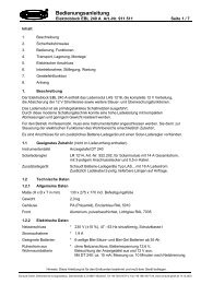
1 Safety Information<br />
1.1 Meaning of safety symbols<br />
Y DANGER!<br />
Failure to heed this warning may result in death or serious injury.<br />
Y WARNING!<br />
Failure to heed this warning may result in personal injuries.<br />
Y ATTENTION!<br />
Failure to heed this warning may result in damage to the device or connected<br />
consumers.<br />
1.2 General safety information<br />
The device is state-of-the-art and complies with approved safety regulations.<br />
Nonetheless, personal injuries or damage to the device may occur if the safety<br />
instructions contained herein are not followed.<br />
Ensure that the device is in perfect working order before use.<br />
Any technical faults which may impact personal safety or the safety of the<br />
device must be rectified immediately by qualified personnel.<br />
Y DANGER!<br />
230 V mains voltage carrying parts.<br />
Danger of death due to electric shock or fire:<br />
F Do not carry out maintenance or repair work on the device.<br />
F If cables or the device housing are damaged, no longer use the<br />
device and isolate from the power supply.<br />
F Ensure that no liquids enter the device.<br />
F The mains connection line may only be replaced by an authorised<br />
customer service department or by qualified persons.<br />
Y WARNING!<br />
Hot components!<br />
Burns:<br />
F Only change blown fuses when the device is completely de-energised.<br />
F Only replace blown fuses once the cause of the fault has been identified<br />
and rectified.<br />
F Never bypass or repair fuses.<br />
F Only use original fuses rated as specified on the device.<br />
F Device parts can become hot during operation. Do not touch.<br />
F Never store heat sensitive objects close to the device (e.g. temperature<br />
sensitive clothes if the device has been installed in a wardrobe).<br />
2 Date: 30.09.2008 811.553 BA / EN
12 V main switch<br />
(on DT ... control and<br />
switch panel)<br />
811.553 BA / EN<br />
2 Introduction<br />
<strong>Instruction</strong> <strong>Manual</strong> <strong>Electrobloc</strong> <strong>EBL</strong> <strong>101</strong> C<br />
This instruction manual contains important information on the safe operation<br />
of equipment supplied by Schaudt. Ensure you read and follow the safety instructions<br />
provided.<br />
The instruction manual should be kept in the vehicle at all times. Ensure that<br />
other users are made aware of the safety regulations.<br />
Y This device is not intended to be used by persons (including children)<br />
with limited physical, sensory or mental aptitude or lack of experience<br />
and/or knowledge unless they are supervised by a person responsible for<br />
their safety or have received instruction from this person as to how the<br />
device is used.<br />
Children are to be supervised so as to ensure they do not play with the<br />
device.<br />
This device is intended for installation into a vehicle.<br />
3 Operation<br />
The <strong>Electrobloc</strong> is operated solely from the DT ... control and switch panel<br />
connected (apart from battery isolation).<br />
The <strong>EBL</strong> <strong>Electrobloc</strong> <strong>101</strong> C does not require daily operation.<br />
Initial settings are only required after the type of battery (lead-acid or leadgel)<br />
has been changed or during commissioning or when upgrading with accessories<br />
(see section 3.2 and <strong>EBL</strong> <strong>101</strong> C installation instructions for details).<br />
3.1 Switching system on/off<br />
Y ATTENTION!<br />
Incorrect <strong>Electrobloc</strong> settings.<br />
Damage to connected devices. Therefore prior to starting:<br />
F Ensure the leisure battery is connected.<br />
F Ensure that the battery selector switch (Fig. 1, Pos. 1) is set to the<br />
correct position for the inserted battery.<br />
F Ensure that the AES fuse (Fig. 4, Pos. 16) is only inserted if an AES<br />
refrigerator is connected to the system. Otherwise, the leisure battery<br />
may totally discharge. Damage to the battery is possible.<br />
Disable battery isolation on <strong>Electrobloc</strong>:<br />
� Move slide switch (see Fig. 4, Pos. 15) into position ”Battery ON”<br />
� After disabling the battery cut-off switch or after changing batteries: 12 V<br />
main switch on the DT ... control and switch panel must be turned on<br />
briefly to start up the consumers.<br />
Date: 30.09.2008<br />
3
<strong>Instruction</strong> <strong>Manual</strong> <strong>Electrobloc</strong> <strong>EBL</strong> <strong>101</strong> C<br />
Step switch<br />
Operation with solar<br />
regulator<br />
Use the 12 V main switch (see instruction manual of relevant control and<br />
switch panel) to switch on/off all the consumers and the control and switch<br />
panel.<br />
Exceptions:<br />
F Heater<br />
F Step<br />
F Frost protection valve<br />
F AES/compressor refrigerator<br />
F Spare 4<br />
For more information, see the DT ... control and switch panel instruction manual.<br />
The supply to the step is protected by a self-resetting fuse. This is why the<br />
step switch may only be activated briefly.<br />
Y ATTENTION!<br />
Activating the step switch too long results in too high a current.<br />
Self-resetting fuse can activate:<br />
F Only press the step switch briefly.<br />
� If the self-resetting fuse has triggered, it needs about one minute to reset<br />
before the step switch can be pressed again.<br />
Y ATTENTION!<br />
No battery buffer function!<br />
Damage to connected devices:<br />
F Do not operate solar regulator without battery connected.<br />
3.2 Changing the battery<br />
Y ATTENTION!<br />
Use of incorrect battery types or incorrectly rated batteries.<br />
Damage to the battery or devices connected to the electronic block:<br />
F Batteries should only be changed by qualified personnel.<br />
F Follow the instructions of the battery manufacturer.<br />
F Only connect the electronic block to 12 V power supplies with rechargeable<br />
6-cell lead gel or lead acid batteries. Do not use any unsuitable<br />
battery types.<br />
Y Only batteries of the same type and capacity should normally be used,<br />
i.e. same as those installed by the manufacturer.<br />
Y It is possible to swap lead acid batteries with lead gel batteries. Changing<br />
from lead gel batteries to lead acid batteries is not possible without overhead.<br />
Contact the vehicle manufacturer for more information.<br />
4 Date: 30.09.2008 811.553 BA / EN
Changing the battery<br />
811.553 BA / EN<br />
Starting up<br />
the System<br />
<strong>Instruction</strong> <strong>Manual</strong> <strong>Electrobloc</strong> <strong>EBL</strong> <strong>101</strong> C<br />
� Disconnect the battery from the <strong>Electrobloc</strong> by activating the battery isolation<br />
on the DT ... control and switch panel (see also section 3.4).<br />
� Remove ”+ solar cell” connector on the solar charge regulator (if available).<br />
� Isolate <strong>Electrobloc</strong> from the mains voltage (230 V AC).<br />
� Replace battery.<br />
� After changing the battery, recheck which type of battery has been inserted.<br />
Y DANGER!<br />
Incorrect setting of the battery selector switch.<br />
Risk of explosion due to build up of explosive gases:<br />
F Set the battery selector switch to the correct position.<br />
Y ATTENTION!<br />
Incorrect setting of the battery selector switch.<br />
Damage to the battery.<br />
F Set the battery selector switch to the correct position.<br />
� Disconnect the electronic block from the mains before adjusting the battery<br />
selector switch.<br />
Fig. 1 Battery selector switch<br />
Date: 30.09.2008<br />
1<br />
� Set the battery selector switch (Fig. 1, Pos. 1) to the correct position<br />
using a thin object (such as a ballpoint pen):<br />
F Lead gel battery: Set the battery selector switch to ”Lead-gel”.<br />
F Lead acid battery: Set the battery selector switch to ”Lead-acid”.<br />
� Remove ”+ solar cell” connector on the solar charge regulator (if available).<br />
� Start up the system as described in section 3.1.<br />
5
<strong>Instruction</strong> <strong>Manual</strong> <strong>Electrobloc</strong> <strong>EBL</strong> <strong>101</strong> C<br />
Flatvehicle fuses<br />
Self-resetting fuses<br />
3.3 System Faults<br />
A fault in the power supply system is usually caused by a blown fuse.<br />
The following functions are protected by a self-resetting fuse:<br />
F Exit step<br />
F Sensor lines to the DT ... control and switch panel<br />
If there is a fault with the step, it must not be operated for a period of 1 minute.<br />
This fuse resets automatically during this period.<br />
For faults to the DT ... control and switch panel, the entire system is to be<br />
switched off via the battery cut-off and turned on again after about 1 minute.<br />
Please contact our customer service address if you are unable to rectify the<br />
fault using the following table.<br />
If this is not possible, e.g. if you are abroad, you can have the electronic bloc<br />
repaired at a specialist workshop. Please note that the warranty will become<br />
void if incorrect repair work is carried out. Schaudt GmbH shall not accept<br />
liability for any damages resulting from such repairs.<br />
Y The use of an overvoltage protection OVP is recommended.<br />
Fault Possible cause Remedy<br />
Living area battery is not<br />
charged g duringg 230 V<br />
operation ti (battery (b tt voltage lt<br />
constantly below 13 13.33 V)<br />
Living area battery is<br />
overcharged during 230 V<br />
operation (battery voltage<br />
constantly above 14.5 V)<br />
No mains voltage Switch on the automatic<br />
fuse in the vehicle<br />
Have the mains voltage<br />
checked<br />
Defective electronic block Contact the customer<br />
service department<br />
Defective electronic block Contact the customer<br />
service department<br />
Starter battery is not No mains voltage Switch on the automatic<br />
charged during 230 V<br />
fuse in the vehicle<br />
operation ti (battery (b tt voltage lt<br />
constantly below 13.0 V)<br />
Have the mains voltage<br />
checked<br />
Defective electronic block Contact the customer<br />
service department<br />
Livingg area batteryy is not Defective alternator Check the alternator<br />
charged h d during d i mobile bil<br />
operation (battery voltage<br />
No voltage on D+ input Check fuses and wiring<br />
below 13.0 V) Defective electronic block Contact the customer<br />
service department<br />
Thelivingareabatteryis<br />
overcharged during<br />
mobile operation (battery<br />
voltage constantly above<br />
14.3 V)<br />
Defective alternator Check the alternator<br />
The refrigerator does not<br />
work during g mobile<br />
operation ti<br />
No power supply to the<br />
refrigerator<br />
Check fuse and wiring<br />
Defective electronic block Contact the customer<br />
service department<br />
Defective refrigerator Check the refrigerator<br />
6 Date: 30.09.2008 811.553 BA / EN
811.553 BA / EN<br />
<strong>Instruction</strong> <strong>Manual</strong> <strong>Electrobloc</strong> <strong>EBL</strong> <strong>101</strong> C<br />
Fault Possible cause<br />
Remedy<br />
Solar charger does not<br />
work (power supply and<br />
engine g are off) )<br />
Date: 30.09.2008<br />
Solar panel in (partial)<br />
shade or covered (snow or<br />
dirt)<br />
Move solar panel out of<br />
shade or clean.<br />
Solar charge regulator not Plug in solar charge<br />
plugged in<br />
regulator<br />
Defective fuse or wiring Check fuse and wiring<br />
Solar charge regulator<br />
defective<br />
Check solar charge<br />
regulator<br />
12 V supply does not work 12 V main switch for the 12 V main switch for the<br />
in the livingg area<br />
livingg area batteryy is livingg area batteryy must be<br />
switched off<br />
switched on<br />
The <strong>Electrobloc</strong> cannot be<br />
operated from the DT ...<br />
control and switch panel<br />
Activate battery isolation<br />
on the DT ... control and<br />
switch panel<br />
Activate battery isolation<br />
on the DT ... control and<br />
switch panel<br />
Defective fuse or wiring Check fuse and wiring<br />
Defective electronic block Contact the customer<br />
service department<br />
Defective electronic block Contact the customer<br />
service department<br />
Y If the device becomes too hot due to excessive ambient temperature or<br />
lack of ventilation, the charging current is automatically reduced. Nevertheless,<br />
always prevent the device from overheating.<br />
Y If the automatic shutdown mechanism of the battery monitor is triggered,<br />
fully charge the living area battery.<br />
3.4 Closing down the System<br />
Y ATTENTION!<br />
Total discharge.<br />
Damage to the living area battery:<br />
F Fully charge the living area battery before and after closing down the<br />
system. (Connect a vehicle with an 80 Ah battery and a vehicle with a<br />
160 Ah battery to the mains for at least 12 and 24 hours respectively).<br />
Y ATTENTION!<br />
Permitted input voltages exceeded.<br />
Damage to connected consumers:<br />
F Do not operate any connected Schaudt solar charge regulator without<br />
battery.<br />
F If the battery is to be changed or removed, first remove ”+ solar cell”<br />
connector on the solar charge regulator.<br />
7
<strong>Instruction</strong> <strong>Manual</strong> <strong>Electrobloc</strong> <strong>EBL</strong> <strong>101</strong> C<br />
Shutdown of system up<br />
to 6 months<br />
Disconnect the living<br />
area battery from the<br />
12 V power supply<br />
Shutdown period longer<br />
than 6 months<br />
� Fully charge the living area battery before closing down the system.<br />
The living area battery is then protected against total discharge. This only<br />
applies if the battery is intact. Follow the instructions of the battery manufacturer.<br />
The shut down system requires approx. 4 Ah per month.<br />
Disconnect the living area battery from the 12 V power supply if the motorhome<br />
is not used for a longer period (during the winter for example). For<br />
this, the system has a battery cut-off mechanism that isolates the living area<br />
battery from the vehicle. Battery isolation is activated from the DT ... control<br />
and switch panel (see DT ... control and switch panel instruction manual).<br />
� 12 V main switch on the DT ... control and switch panel must be switched<br />
off.<br />
� Move battery cut-off switch (sliding switch, see Fig. 4, Pos. 15) to position<br />
”Battery OFF”.<br />
The battery cut-off switch isolates the following connections from the living<br />
area battery:<br />
F 12 V consumers<br />
F Frost protection valve<br />
F Control and switch panel<br />
Y The living area battery can also be charged using the internal charger<br />
module, an auxiliary battery charging unit, the solar charge regulator and<br />
the alternator when the battery cut-off switch is switched off.<br />
� Fully charge the living area battery before closing down the system.<br />
� Remove the ”+ solar cell” connector on the solar charge regulator.<br />
� Remove the clamps from the battery poles.<br />
Y The battery alarm is no longer active.<br />
Y The frost protection valve opens for certain heater systems when the living<br />
area battery is isolated from the <strong>Electrobloc</strong>k via the battery cut-off.<br />
The boiler and water tank empty when the frost protection valve is open.<br />
For more information, see the instruction manual of the heater system.<br />
4 Application and Functions in Detail<br />
Y This device is intended solely for installation in a vehicle.<br />
The <strong>EBL</strong> <strong>101</strong> C is the central energy supply unit for all 12 V consumers in<br />
the electrical system on board the motorhome or caravan. It is normally fitted<br />
inside a cabinet or a stowage space and can be accessed from the front<br />
to change a fuse.<br />
8 Date: 30.09.2008 811.553 BA / EN
811.553 BA / EN<br />
Modules<br />
System devices<br />
Protective circuits<br />
Mains connection<br />
Current-carrying<br />
capacity<br />
230 V AC<br />
--<br />
+<br />
Starterbatterie<br />
--<br />
<strong>Instruction</strong> <strong>Manual</strong> <strong>Electrobloc</strong> <strong>EBL</strong> <strong>101</strong> C<br />
+<br />
Wohnraumbatterie<br />
Fig. 2 On-board power supply system<br />
The <strong>EBL</strong> <strong>101</strong> C <strong>Electrobloc</strong> contains:<br />
Date: 30.09.2008<br />
Solarregler<br />
LR / LRS ...<br />
(Zubehör)<br />
Elektroblock<br />
<strong>EBL</strong> <strong>101</strong> C<br />
12-V-Verbraucher<br />
F a charge module for charging all connected batteries<br />
F the complete 12 V distribution<br />
F the fuses for the 12 V circuits<br />
F a main switch module<br />
F other control and monitoring functions<br />
Kontroll- und<br />
Anzeigetafel<br />
DT/LT ...<br />
Zusatz-Lader<br />
LAS ...<br />
(Zubehör)<br />
Beleuchtung<br />
Pumpe<br />
Heizung<br />
etc.<br />
A DT ... control and switch panel must be connected for operation. These<br />
devices control the electrical functions in the motorhome’s living area as well<br />
as the accessories.<br />
There are connections for an additional battery charger and a solar charge<br />
regulator.<br />
Flat vehicle fuses protect the various circuits. Exceptions here are the step<br />
and the frost protection valve.<br />
F Excess temperature<br />
F Overload<br />
F Short circuit<br />
230 V AC ± 10 %, 47 to 63 Hz sinusoidal, protection class I<br />
12 V outputs may be loaded with max. 90% of the rated current of the respective<br />
fuse (see also installation instructions or front panel).<br />
9
<strong>Instruction</strong> <strong>Manual</strong> <strong>Electrobloc</strong> <strong>EBL</strong> <strong>101</strong> C<br />
Suitable batteries<br />
Battery charging<br />
during mobile operation<br />
Battery isolation<br />
Battery selector switch<br />
Battery monitor with<br />
automatic disconnect<br />
4.1 Battery functions<br />
6-cell lead acid or lead gel batteries, 55 Ah and above<br />
Simultaneous charging of the starter battery and the living area battery via<br />
the alternator, parallel connection of the batteries via a cut-off relay<br />
The battery cut-off (at the battery cut-off switch of the <strong>Electrobloc</strong>, see Fig.<br />
4, Pos. 15, see also section 3.4) isolates the following connections from the<br />
living area battery:<br />
F all 12 V consumers<br />
F the frost protection valve<br />
This prevents slow discharge of the living area battery by the standby current<br />
during shutdown of the vehicle (discharge with approx. 4 Ah in month).<br />
The batteries can still be charged using the <strong>Electrobloc</strong>, the alternator, an<br />
auxiliary charging unit or the solar charge regulator, even when the battery<br />
cut-off switch is switched off.<br />
The switching option provided by the battery selector switch ensures optimum<br />
charging of the two battery types, lead gel and lead acid.<br />
The battery monitor of the DT ... control and switch panel constantly monitors<br />
the living area battery with dynamic voltage threshold. Lower discharge<br />
currents cut off ”earlier” than with larger currents. This provides improved total<br />
discharge protection. Monitoring is also performed in the switched-off<br />
state. A warning message is displayed below 12.0 V (dependent on current<br />
drain).<br />
If the voltage of the living area battery sinks further, falling below 10.5 V, the<br />
battery monitor immediately switches off all 12 V consumers. The control<br />
and switch panel also switches itself off. Only the frost protection valve continues<br />
to be powered (so it stays closed). Before switch-off, all switch states<br />
and the value of the battery capacity are stored and restored after power-on.<br />
If an overload or an insufficiently charged living area battery causes the voltage<br />
to fall so low that the automatic disconnector is triggered, any non-essential<br />
consumers should be switched off.<br />
If need be, the 12 V supply can begin operation for a short time. In this case<br />
the 12 V main switch on the DT ... control and switch panel must be switched<br />
on.<br />
However, if the battery voltage remains below 11.0 V, the 12 V power supply<br />
can not be turned back on.<br />
Fully charge the living area battery as soon as possible. For more information,<br />
see the ”Battery voltages” description in the associated DT ... control<br />
and switch panel instruction manual.<br />
10 Date: 30.09.2008 811.553 BA / EN
811.553 BA / EN<br />
Automatic switch<br />
function for<br />
AES/compressor<br />
refrigerator<br />
Step fuse<br />
Battery charging with<br />
solar charging regulator<br />
Cleaning<br />
4.2 Additional functions<br />
<strong>Instruction</strong> <strong>Manual</strong> <strong>Electrobloc</strong> <strong>EBL</strong> <strong>101</strong> C<br />
This relay supplies the AES/compressor refrigerator with power from the<br />
starter battery when the vehicle engine is running and the D+ connection is<br />
live. An AES/compressor refrigerator is powered by the living area battery<br />
when the vehicle engine is not running.<br />
The step output is protected by a self-resetting 15 A fuse.<br />
If a fault occurs, such as overcurrent, the self-resetting fuse interrupts the<br />
relevant circuit.<br />
After rectification of the fault, the fuse automatically resets after approx. 1<br />
minute.<br />
Maximum permitted charge current 14 A, protected with 15 A<br />
Depending on the solar charge regulator used, either only the living area<br />
battery is charged or the living area battery and the starter battery.<br />
4.3 Use as an exchange device<br />
The <strong>EBL</strong> <strong>101</strong> C can be used as an exchange device for the <strong>EBL</strong> 100. The<br />
plug-and-socket connections of the old device can all be used.<br />
Some additional functions and plug connections of the <strong>EBL</strong> <strong>101</strong> C will however<br />
remain without a function.<br />
5 Maintenance<br />
E<br />
The <strong>Electrobloc</strong> requires no maintenance.<br />
Clean the electronic block with a soft, slightly damp cloth and mild detergent.<br />
Never use spirit, thinners or similar substances. Do not allow liquids to enter<br />
the electronic block.<br />
No part of this manual may be reproduced, translated or copied without express<br />
written permission.<br />
Date: 30.09.2008<br />
11
<strong>Instruction</strong> <strong>Manual</strong> <strong>Electrobloc</strong> <strong>EBL</strong> <strong>101</strong> C<br />
Manufacturer<br />
Address<br />
Switch panel<br />
Additional charger<br />
Solar charge regulator<br />
Customer service<br />
address<br />
Send in the device<br />
Appendix<br />
A EC Declaration of Conformity<br />
Schaudt GmbH hereby confirms that the <strong>EBL</strong> <strong>101</strong> C <strong>Electrobloc</strong> de<br />
-- DIRECTIVE 2006/95/EC OF THE EUROPEAN PARLIAMENT AND<br />
COUNCIL from 12.12.2006 for the harmonization of the legal provisions<br />
of member states in regard to electrical equipment for use within<br />
particular voltage limits<br />
-- DIRECTIVE 2004/108/EC OF THE EUROPEAN PARLIAMENT AND<br />
COUNCIL from 15.12.2004 for the harmonization of the legal provisions<br />
of member states in regard to electromagnetic compatibility and<br />
for the annulment of directive 89/336/EEC<br />
-- Law on the electromagnetic compatibility of equipment from February<br />
26th 2008<br />
Schaudt GmbH, Elektrotechnik & Apparatebau<br />
Daimlerstrasse 5<br />
88677 Markdorf<br />
Germany<br />
B Special fittings/accessories<br />
Schaudt DT ... switch panel (required for operation)<br />
Schaudt battery charger LAS ... with max. 18 A charge currency, including<br />
suitable connection cable (MNL).<br />
Schaudt Solar charge regulator, type LR ... (or LRS ... ; required if the solar<br />
current is to be displayed) for solar modules with an overall current of 14 A<br />
with 3-pin connector and connector cable (LRS ... with 2 connectors)<br />
C Customer service<br />
Schaudt GmbH, Elektrotechnik & Apparatebau<br />
Daimlerstrasse 5<br />
D-88677 Markdorf<br />
tel.: +49 7544 9577-16 e-mail: kundendienst@schaudt-gmbh.de<br />
Office hours Mon to Thurs 08.00 -- 12.00, 13.00 -- 16.00<br />
Fri 08.00 -- 12.00<br />
Returning a defective device:<br />
� Fill in and enclose the fault report, see Appendix D.<br />
� Send it to the addresse (free of charge).<br />
12 Date: 30.09.2008 811.553 BA / EN
Mains connection<br />
Current consumption<br />
Standby current from<br />
living area battery<br />
811.553 BA / EN<br />
D+ loading<br />
Current-carrying<br />
capacity<br />
D Fault report<br />
<strong>Instruction</strong> <strong>Manual</strong> <strong>Electrobloc</strong> <strong>EBL</strong> <strong>101</strong> C<br />
In the event of damage, please return the defective device together with the<br />
completed fault report to the manufacturer.<br />
Device type: _______________________<br />
Article no.: _______________________<br />
Vehicle: Manufacturer: _______________________<br />
Model: _______________________<br />
Own installation? Yes - No -<br />
Upgrade?<br />
Following fault has occurred (please tick):<br />
Yes - No -<br />
- Electrical consumers do not work -- which?<br />
(please specify below)<br />
- Switching on and off not possible<br />
- Persistent fault<br />
- Intermittent fault/loose contact<br />
Other remarks:<br />
E Technical data<br />
230 V AC ± 10%, 47 to 63 Hz sinusoidal, protection class I<br />
1.9 A<br />
Depending on the control and switch panel: approx. 5 -- 20 mA, plus consumption<br />
of controller electronics of refrigerator<br />
Measurement approx. 10 minutes after disconnection from the mains:<br />
F not connected to mains<br />
F 12.6 V battery voltage<br />
F Battery isolation not enabled<br />
F Control and switch panel lighting off<br />
F 12 V main switch off<br />
Loading of D+ output of the alternator by the <strong>Electrobloc</strong> approx. 200 mA<br />
without current consumption on D+ point<br />
12 V outputs A maximum of 90% of the nominal<br />
current of the relevant fuse may be<br />
drawn.<br />
Date: 30.09.2008<br />
13
<strong>Instruction</strong> <strong>Manual</strong> <strong>Electrobloc</strong> <strong>EBL</strong> <strong>101</strong> C<br />
Battery charging, living<br />
area battery with mains<br />
connection<br />
Battery charging, starter<br />
battery with mains<br />
connection<br />
Battery charging via<br />
solar charge regulator<br />
Battery charging<br />
during mobile operation<br />
Battery monitor<br />
Frost protection valve output max. 0.1 A<br />
D+ point max 1 A<br />
Characteristic charging curve IUoU<br />
Final charging voltage 14.3 V<br />
Charge current 18 A in the entire mains voltage range,<br />
electronically limited, minus the<br />
charge current into the vehicle battery<br />
Voltage for float charge 13.8 V with automatic switchover<br />
New charge cycle, with battery voltage below 13.8 V<br />
Switchover to main charging with a few seconds delay<br />
Solar<br />
charging<br />
V<br />
14,3<br />
13,8<br />
Main charge<br />
I<br />
Full charge<br />
Uo<br />
1 h with lead acid<br />
8 h with lead gel<br />
Float charge<br />
U<br />
Fig. 3 Example of the charging voltage curve on the <strong>EBL</strong> <strong>101</strong> C <strong>Electrobloc</strong><br />
I Main charge with maximum 18 A charging current, electronically limited,<br />
up to final charging voltage. Start of charge also for totally discharged<br />
batteries.<br />
Uo Automatic changeover to full charge with constant 14.3 V. The duration<br />
of the fully charge phase depends on the type of battery and can be<br />
adjusted at the device:<br />
U Automatic changeover to trickle charge with constant 13.8 V. In the<br />
trickle charge phase, the voltage at the output of the charging module<br />
is constant.<br />
Start of a new charging cycle by switching over to main charge, if the battery<br />
voltage falls below 13.8 V for more than 5 seconds when loaded. Start of<br />
charge also for totally discharged batteries. The internal charge module can<br />
also be operated without living area battery.<br />
For mains operation, the starter battery is also charged (with maximum<br />
charge current of 6 A).<br />
Maximum permitted charge current 14 A, protected with 15 A;<br />
Depending on the solar charge regulator used, either only the living area<br />
battery is charged or the living area battery and the starter battery.<br />
14 Date: 30.09.2008 811.553 BA / EN<br />
Time<br />
Simultaneous loading of living area battery by alternator<br />
Batteries connected in parallel via a cut-off relay<br />
Switch-off voltage: dynamic,<br />
controlled by control and switch panel<br />
Minimum battery voltage for approx. 11.0 V<br />
Switch-on via the<br />
12 V main switch on the<br />
control and switch panel:
F Design<br />
1<br />
19 18 17 16 15<br />
Fig. 4 Design of the <strong>EBL</strong> <strong>101</strong> C <strong>Electrobloc</strong> (front)<br />
1 Mains connector<br />
2 Connection block, refrigerator supply<br />
3 Connector block, refrigerator supply D+,<br />
Battery sensor/control lines<br />
4 Connector block, heating, floor light, step<br />
5 Connector, DT ... control and switch panel<br />
6 Connector, DT ... control and switch panel<br />
7 Connection block, solar regulator (measurement<br />
signal)<br />
8 Connection block, reserve<br />
9 Connection block, solar regulator (supply)<br />
Fig. 5 Design of the <strong>EBL</strong> <strong>101</strong> C <strong>Electrobloc</strong> (rear)<br />
1 Connection, living area battery<br />
2 Connection, earth<br />
811.553 BA / EN<br />
<strong>Instruction</strong> <strong>Manual</strong> <strong>Electrobloc</strong> <strong>EBL</strong> <strong>101</strong> C<br />
2 3 4 5 6 7 8<br />
Date: 30.09.2008<br />
14<br />
9<br />
10<br />
10 Connection block, additional charger<br />
11 Connection block TV, pump, consumers<br />
12 Selector switch acid/gel battery<br />
13 Self resetting step fuse (internal)<br />
14 Flat vehicle fuses, consumers<br />
15 Battery cut-off switch<br />
16 AES refrigerator fuse<br />
17 Flat vehicle fuse, internal charger module<br />
18 Housing<br />
19 Assembly flaps<br />
3<br />
Starter<br />
Battery<br />
+ Negative Battery<br />
Living area<br />
-- +<br />
2<br />
3 Connection, starter battery<br />
1<br />
13<br />
11<br />
12<br />
15
<strong>Instruction</strong> <strong>Manual</strong> <strong>Electrobloc</strong> <strong>EBL</strong> <strong>101</strong> C<br />
G Block diagram/connection diagram<br />
Mains 230 V ∼ 50 Hz<br />
low heat device socket<br />
MS * relay 60<br />
A<br />
Circuit board<br />
Pin rail MSFQ/0 4F-BL10to<br />
LR ... solar regulator<br />
Solar<br />
charge<br />
regulator<br />
LR ...<br />
WB signal<br />
SB signal<br />
[+]WB<br />
SB<br />
[ -- ] Negative<br />
Solar module<br />
[Solar module]<br />
MNL-bush socket 3F-BL6 on<br />
LR ... solar regulator<br />
MNL-bush socket 6F-BL4<br />
Frost protection valve<br />
Heater<br />
Floor light<br />
/Step<br />
MNL-bush socket 12F-BL5<br />
Spare 4B<br />
Spare 4A<br />
Spare 3<br />
Spare 2<br />
MS * relay 60<br />
A<br />
Module HS100<br />
Charging relay<br />
for starter battery<br />
Lead-gel/<br />
lead-acid<br />
switchover<br />
Power supply<br />
switching stage<br />
Refrigerator<br />
relay<br />
Battery<br />
cut--off switch<br />
(off)<br />
Fuse only with<br />
compressor/AES<br />
refrigerator.<br />
MNL-bush socket 2F-BL7 on additional LAS ... charger<br />
Battery<br />
cut--off relay<br />
Negative charging unit<br />
+ Auxiliary charging unit<br />
The negative pole of the living area<br />
battery must be connected externally to<br />
the negative pole of the starter battery<br />
+ Starter battery (Batt. 1)<br />
+ living room batt. (Batt. 2)<br />
Negative living area battery<br />
Pin rail MSFQ/0 12F-BL3to DT ... digital panel<br />
Mains indicator<br />
Shunt battery<br />
Shunt consumer<br />
MS relay 1 On<br />
MS relay 1 Off<br />
Minus sensor living area battery (batt. 2)<br />
MS relay 2 On<br />
MS relay 2 Off<br />
Negative lighting<br />
+ Lighting<br />
+ sensor living area battery (batt. 2)<br />
+ Starter battery (Batt.1)<br />
Pin rail MSFQ/0 7F-BL9to DT ... digital panel<br />
D+ point<br />
Signal solar living area battery<br />
Signal solar starter battery<br />
MNL-bush socket 5F-BL2<br />
MNL-bush socket 4F-BL1<br />
MNL-bush socket 5F-BL8<br />
+ sensor living area battery<br />
Negative sensor living area battery<br />
+ Starter batt. for refrigerator*<br />
D+ input<br />
Negative starter battery for refrigerator*<br />
16 Date: 30.09.2008 811.553 BA / EN<br />
nc<br />
nc<br />
nc<br />
nc<br />
* Refrigerator lines must be lead to<br />
the battery poles without being<br />
connected to other battery supplies<br />
every 1.5 mm2 max. 10 m<br />
+ Compressor/AES refrigerator<br />
+ Absorber refrigerator*<br />
D+ point<br />
Negative refrigerator<br />
D+ point<br />
TV<br />
Pump<br />
Circuit 1<br />
Circuit 2<br />
Spare 1<br />
Spare 5<br />
Spare 6