Optical feedback in diode lasers
Optical feedback in diode lasers
Optical feedback in diode lasers
- No tags were found...

You also want an ePaper? Increase the reach of your titles
YUMPU automatically turns print PDFs into web optimized ePapers that Google loves.
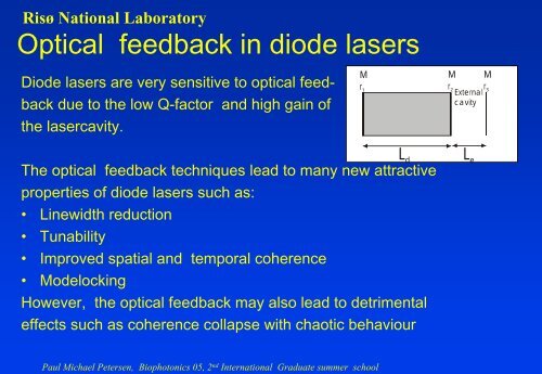
Risø National Laboratory<br />
<strong>Optical</strong> <strong>feedback</strong> <strong>in</strong> <strong>diode</strong> <strong>lasers</strong><br />
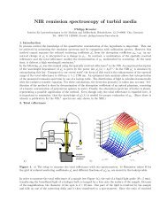
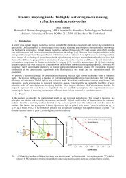
Diode <strong>lasers</strong> are very sensitive to optical <strong>feedback</strong><br />
due to the low Q-factor and high ga<strong>in</strong> of<br />
the lasercavity.<br />
M<br />
r 1<br />
M<br />
r 2<br />
External<br />
cavity<br />
M<br />
r 3<br />
The optical <strong>feedback</strong> techniques lead to many new attractive<br />
properties of <strong>diode</strong> <strong>lasers</strong> such as:<br />
• L<strong>in</strong>ewidth reduction<br />
• Tunability<br />
• Improved spatial and temporal coherence<br />
• Modelock<strong>in</strong>g<br />
However, the optical <strong>feedback</strong> may also lead to detrimental<br />
effects such as coherence collapse with chaotic behaviour<br />
L d<br />
L e<br />
Paul Michael Petersen, Biophotonics 05, 2 nd International Graduate summer school
Risø National Laboratory<br />
Threshold ga<strong>in</strong> and oscillation frequency<br />
A coupled cavity model may be used for the analysis of<br />
<strong>diode</strong> <strong>lasers</strong> with optical <strong>feedback</strong>.<br />
M<br />
r 1<br />
M<br />
M<br />
M<br />
r 2<br />
r<br />
External 3<br />
r 1<br />
cavity<br />
At threshold the oscillation condition is:<br />
L d<br />
M<br />
r ( ) eff ω)<br />
( gth − αm ) Ld iωτ<br />
r2 +<br />
d<br />
3<br />
1 eff<br />
( ω) = 1 where r<br />
eff( ω)<br />
=<br />
1 +<br />
2 3<br />
rr e e<br />
re<br />
rre<br />
where τ d =2n d L d /c and τ e =2L e /c are the round-trip times.<br />
iωτ<br />
e<br />
iωτ<br />
e<br />
Paul Michael Petersen, Biophotonics 05, 2 nd International Graduate summer school
Risø National Laboratory<br />
Threshold ga<strong>in</strong> and oscillation frequency<br />
The ga<strong>in</strong> and the oscillations frequency can be obta<strong>in</strong>ed from the ”oscillations<br />
condition by solv<strong>in</strong>g this equation for the amplitude and phase:<br />
g<br />
= α −<br />
1 ln[ r r ( ω ) ]<br />
th m 1 eff<br />
Ld<br />
1 reff<br />
( ω)<br />
ω − ωq<br />
=− [ α ln[ ] − Arg [ reff<br />
( ω )]<br />
τ r<br />
d<br />
Paul Michael Petersen, Biophotonics 05, 2 nd International Graduate summer school<br />
2<br />
Where ω q =2 πq/τ d is the frequency of the laser <strong>diode</strong> without <strong>feedback</strong> and<br />
where an additional phaseshift has been <strong>in</strong>cluded due to the carrier <strong>in</strong>duced<br />
variation of the refractive <strong>in</strong>dex by the α parameter given by:<br />
dn / dN<br />
α =−2<br />
k dg / dN<br />
where n is the refractive <strong>in</strong>dex, g is the ga<strong>in</strong> and N is the carrier density.
Risø National Laboratory<br />
L<strong>in</strong>ewidth reduction with external <strong>feedback</strong> cavities<br />
The l<strong>in</strong>ewidth reduction is given by<br />
dωq<br />
∆ ν =∆ν0( )<br />
dω<br />
where<br />
−2<br />
dωq 1 dln reff ( ω) dln reff<br />
( ω)<br />
= 1 + { α Re[ ] −Im[ ]}<br />
dω τ dω dω<br />
d<br />
where ∆ν 0 is the l<strong>in</strong>ewidth without <strong>feedback</strong> and dω q / dω is the frequencychirp<br />
reduction factor.<br />
Paul Michael Petersen, Biophotonics 05, 2 nd International Graduate summer school
Risø National Laboratory<br />
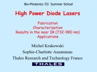
Stability regimes for <strong>lasers</strong> with optical <strong>feedback</strong><br />
M<br />
r 1<br />
M<br />
r 2<br />
External<br />
cavity<br />
M<br />
r 3<br />
Regime I: Stable regime where the l<strong>in</strong>ewidth is<br />
narrowed or broadened broadened depend<strong>in</strong>g<br />
on the phase of the <strong>feedback</strong><br />
Regime II: Conditionally stable<br />
Regime III: Stable s<strong>in</strong>gle mode operation is<br />
obta<strong>in</strong>ed with l<strong>in</strong>ewidth reduction<br />
Regime IV: Unstable operation with coherence<br />
collapse<br />
Regime V: Stable operation with significant<br />
l<strong>in</strong>ewidth reduction<br />
Paul Michael Petersen, Biophotonics 05, 2 nd International Graduate summer school<br />
L d<br />
L e
Risø National Laboratory<br />
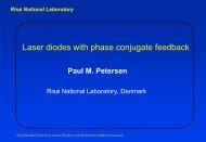
<strong>Optical</strong> <strong>feedback</strong> <strong>in</strong> the Littrow configuration<br />
Laser <strong>diode</strong><br />
HR<br />
AR<br />
Grat<strong>in</strong>g<br />
In the Littrow configuration the first order diffraction is feed back to the laser<br />
and the zero order diffraction is used as an output beam. The wavelenght<br />
tun<strong>in</strong>g range is typycally 10-50 nm which is limited by the bandwidth of the<br />
semiconductor ga<strong>in</strong> medium. Usually high quality antireflection coat<strong>in</strong>g on<br />
the output facet is required to prevent self oscillation <strong>in</strong> the laser <strong>diode</strong>.<br />
The wavelenght is changed due to λ = 2as<strong>in</strong>(θ)<br />
Paul Michael Petersen, Biophotonics 05, 2 nd International Graduate summer school
Risø National Laboratory<br />
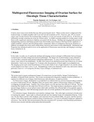
<strong>Optical</strong> <strong>feedback</strong> <strong>in</strong> the Littman configuration<br />
Laser <strong>diode</strong><br />
HR<br />
AR<br />
Grat<strong>in</strong>g<br />
In the Littman configuration the first order diffraction is reflected back from<br />
an additional mirror and the laser beam is coupled out from the zero order<br />
diffraction.<br />
Usually high quality antireflection coat<strong>in</strong>g on the output facet is required.<br />
Coat<strong>in</strong>g with up to 5% reflectivity has been used but with limited tun<strong>in</strong>g<br />
range. <strong>Optical</strong> <strong>feedback</strong> of the order of 20 % to 30 % is needed.<br />
Paul Michael Petersen, Biophotonics 05, 2 nd International Graduate summer school