Pressure Control Valves - Mankenberg
Pressure Control Valves - Mankenberg
Pressure Control Valves - Mankenberg

You also want an ePaper? Increase the reach of your titles
YUMPU automatically turns print PDFs into web optimized ePapers that Google loves.
Page No. RP 814, 815/2.1.124.1 - Standing 11.01.2012 MANKENBERG GmbH | Spenglerstraße 99 | D-23556 Lübeck www.mankenberg.de | Tel. +49 (0) 451 - 8 79 75 0<br />
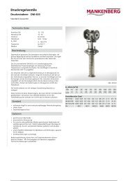
<strong>Pressure</strong> <strong>Control</strong> <strong>Valves</strong><br />
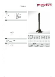
Pilot-operated <strong>Control</strong> <strong>Valves</strong> RP 814, 815<br />
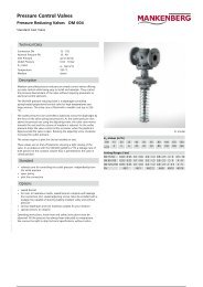
Pilot-operated <strong>Pressure</strong> Reducing Valve<br />
Technical Data<br />
Connection DN 100 - 800<br />
Nominal <strong>Pressure</strong> PN 16 - 25<br />
Inlet <strong>Pressure</strong> up to 25 bar<br />
Outlet <strong>Pressure</strong> 1 - 20 bar<br />
Differential <strong>Pressure</strong> min. 2 bar<br />
K vs-Value<br />
60 - 2100 m 3 /h<br />
Temperature 130 °C<br />
Medium liquids and gases<br />
Description<br />
Medium-controlled pressure reducers are simple control valves offering<br />
accurate control while being easy to install and maintain. They control<br />
the pressure downstream of the valve without requiring pneumatic or<br />
electrical control elements.<br />
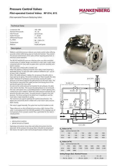
The RP 814 and RP 815 pressure reducing valves are pilot-controlled<br />
control valves of tubular design consisting of a main valve, a pilot valve<br />
connected with the main valve via pipes and a restrictor assembly with<br />
built-in strainer.<br />
The valve cone is fitted with a metallic seal.<br />
When the pipeline is depressurised the main valve is kept closed by a<br />
preloaded spring. To open the valve a pressure difference (p1 – p2) of<br />
at least 2 bar is required.<br />
When the outlet pressure is below the set pressure the pilot valve is<br />
kept open by its spring. The control medium can flow towards the valve<br />
outlet. Restrictor D1 produces a pressure drop causing the outlet<br />
pressure to be almost equal to the pilot pressure in the main valve. The<br />
inlet pressure overcomes the outlet pressure and closing force of the<br />
spring and opens the main valve.<br />
As soon as the outlet pressure has reached the set pressure, the pilot<br />
valve restricts the flow. This causes the pilot pressure to rise and push<br />
the main valve piston into a controlling position in which opening and<br />
closing forces are in balance. When the outlet pressure exceeds the set<br />
pressure the pilot valve closes. The pilot pressure is equal to the inlet<br />
pressure. The forces acting on the piston are in equilibrium and the<br />
main valve is kept closed by its spring.<br />
The restrictors are used to optimise the control characteristics. The<br />
bypass line around D2 which is fitted with a non-return valve, ensures<br />
quick closing.<br />
The valve is piped internally. The pulse lines must be installed on-site.<br />
These valves are no shut-off elements ensuring a tight closing of the<br />
valve. In accordance with the VDI/VDE guideline 2174 a leakage rate of<br />
0.05 percent of the constant volume flow is permitted for the valve in<br />
closed position.<br />
Options<br />
» electrical limit switches<br />
» special versions on request<br />
Operating instructions, know how and safety instructions must be<br />
observed. All the pressure has always been indicated as overpressure.<br />
We reserve the right to alter technical specifications without notice.<br />
K vs-Values [m 3 /h]<br />
type nominal diameter DN<br />
100 125 150 200 250 300<br />
814 60 100 120 180 250 400<br />
815 180 200 250 400 600 800<br />
K vs-Values [m 3 /h]<br />
type nominal diameter DN<br />
350 400 450 500 600 700 800<br />
814 600 800 1100 1200 1800 2000 2100<br />
815 1200 1800<br />
Setting Ranges [bar], Nominal <strong>Pressure</strong><br />
1 - 5 4 - 12 10 - 20<br />
PN 16 - 25/10 PN 16 - 25/25 PN 16 - 25/40
Page No. RP 814, 815/2.1.124.2 - Standing 11.01.2012 MANKENBERG GmbH | Spenglerstraße 99 | D-23556 Lübeck www.mankenberg.de | Tel. +49 (0) 451 - 8 79 75 0<br />
<strong>Pressure</strong> <strong>Control</strong> <strong>Valves</strong><br />
Pilot-operated <strong>Control</strong> <strong>Valves</strong> RP 814, 815<br />
Pilot-operated <strong>Pressure</strong> Reducing Valve<br />
Materials<br />
Temperature 80 °C 130 °C<br />
Body steel optional CrNiMo-steel welded<br />
Internals CrNiMo-steel CrNiMo-steel<br />
Valve Seal CrNiMo-steel CrNiMo-steel<br />
O-Ring NBR EPDM<br />
Pilot Valve CrNiMo-steel CrNiMo-steel<br />
Sense Line<br />
Throttle Unit<br />
Dimensions [mm] RP 814<br />
size nominal diameter DN<br />
100 125 150 200 250 300 350 400 450 500 600 700 800<br />
A 300 325 350 400 450 500 550 600 650 700 800 900 1000<br />
B max. 200 200 220 240 270 300 320 350 380 400 450 500 550<br />
E max. 270 270 270 270 270 270 270 270 270 270 270 270 270<br />
Weights [kg] RP 814<br />
PN nominal diameter DN<br />
100 125 150 200 250 300 350 400 450 500 600 700 800<br />
16 60 60 65 75 120 150 190 240 300 360 420 480 540<br />
25 75 75 80 90 135 165 220 280 360 400 460 580 720<br />
Dimensions [mm] RP 815<br />
size nominal diameter DN<br />
100 125 150 200 250 300 350 400<br />
A 350 400 480 600 730 850 980 1100<br />
B max. 220 240 270 300 320 350 400 450<br />
øD max. 360 400 425 485 555 620 730 845<br />
E max. 270 270 270 270 270 270 270 270<br />
Weights [kg] RP 815<br />
PN nominal diameter DN<br />
100 125 150 200 250 300 350 400<br />
16 85 110 125 170 220 270 340 400<br />
25 90 115 135 180 240 300 370 430<br />
Special designs on request.<br />
The pressure has always been indicated as overpressure.<br />
<strong>Mankenberg</strong> reserves the right to alter or improve the designs or<br />
specifications of the products described herein without notice.<br />
Dimensional Drawing<br />
Recommended Installation<br />
1 Strainer 5 <strong>Pressure</strong> Gauge<br />
2 Shut-off <strong>Valves</strong> 6 Sense Line G 1/2<br />
3 <strong>Pressure</strong> Reducer<br />
4 Safety <strong>Valves</strong><br />
sense line connection 10 - 20 x DN behind the valve<br />
use MANKENBERG-Products