Download brochure 1.8 MB (pdf) - Weishaupt
Download brochure 1.8 MB (pdf) - Weishaupt
Download brochure 1.8 MB (pdf) - Weishaupt
- No tags were found...

Create successful ePaper yourself
Turn your PDF publications into a flip-book with our unique Google optimized e-Paper software.
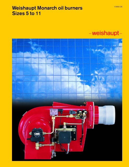
<strong>Weishaupt</strong> Monarch oil burners<br />
Sizes 5 to 11<br />
1/2002 CA<br />
1
Description, Types of regulation,<br />
Model overview<br />
<strong>Weishaupt</strong> Monarch oil burners are of<br />
the fully automatic pressure atomizing<br />
type. Their design has been carefully<br />
considered down to the smallest<br />
detail and has been proven to be<br />
successful over and over again. They<br />
meet all the demands for safety,<br />
reliability and low cost operation.<br />
The burners are distinguished by a<br />
variety of excellent features:<br />
■ Larger range of application<br />
4 - 127 GPH (600 - 18,500 <strong>MB</strong>H)<br />
■ Automatic sequence of operations<br />
■ Stable fan characteristics - good<br />
combustion results<br />
■ Air damper closed on burner<br />
shutdown<br />
■ Quiet operation<br />
■ Complete pre-wired integral<br />
switchgear/ ISG version (except for<br />
RL, RMS and L10T three stage<br />
burners)<br />
■ Hinged burner casing<br />
■ Combustion head can be pulled out<br />
when the burner is hinged open (sizes<br />
9 to 11)<br />
■ The design of the burner makes<br />
installation, adjustment and servicing<br />
easy<br />
Construction<br />
All the components are assembled in one<br />
unit. The motor drives the fan and the fuel<br />
pump. All the equipment used for the<br />
regulation of fuel and air is clearly<br />
arranged and easily accessible. The<br />
burners can be hinged open to the left or<br />
right, which simplifies service work on<br />
the combustion head, diffuser, nozzles<br />
and ignition electrodes.<br />
Application<br />
The burners can be used on hot water<br />
boilers, steam boilers, air heaters and for<br />
various heating processes. RL and RMS<br />
burners are preferably used where there<br />
is a continually changing heat demand.<br />
Fuels<br />
Light oil #2 to Heavy oil #6 fuel.<br />
Viscosity:<br />
Types Monarch L and RL -<br />
up to 6 cSt (6 mm 2 /s) at 68F (20°C)<br />
Type Monarch M -<br />
up to 75 cSt (75 mm 2 /s) at 122F (50°C)<br />
Types Monarch MS and RMS -<br />
up to 50 cSt (50 mm 2 /s) at 212F<br />
(100°C)<br />
Regulation<br />
On L , M and MS type burners, the<br />
regulation of oil and air takes place as<br />
follows:<br />
■ two stage, nozzle head with two<br />
nozzles and a motor controlled,<br />
quickly opening air damper.<br />
■ three stage, with three nozzles and a<br />
motor controlled, slowly opening air<br />
damper.<br />
For RL and RMS burners, fuel and air are<br />
controlled in compound. The burner can,<br />
depending on the controller and<br />
servomotor, be either:<br />
■ sliding two stage<br />
(servomotor with 20 s running time)<br />
■ modulating<br />
(servomotor with 42 s running time)<br />
With sliding two stage regulation, the low<br />
and high fire positions are fixed within the<br />
burner operating range. The burner<br />
slides to one position or the other,<br />
depending on the appliance demand,<br />
and there are no rapid changes of fuel<br />
throughput.<br />
By utilizing a suitable controller, the<br />
burner can be operated in modulating<br />
mode. Modulating burners operate at any<br />
point within the capacity range,<br />
depending on the heat demand.<br />
On sliding two stage burners and<br />
modulating burners, the slow capacity<br />
alteration ensures a particularly good<br />
matching to the demand of the heating<br />
appliance.<br />
Flame safeguard<br />
The burner flame safeguard automatically<br />
sequences the operations and monitors<br />
the flame optically via the flame sensor.<br />
For burners without inbuilt switchgear<br />
the flame safeguard is supplied loose for<br />
mounting in the control panel.<br />
No interference with radio and<br />
television reception<br />
Radio interference created during<br />
ignition is below the permitted limits<br />
specified by the relevant EMC<br />
standards and regulations.<br />
Nozzle recirculation system on<br />
residual oil burners<br />
During prepurge on residual oil burners,<br />
heated oil flows through the nozzle head<br />
and oil line system. This ensures that<br />
evenly heated oil is available for flame<br />
establishment.<br />
Air/gas separator<br />
Oil circulation tank<br />
Patented air/gas separators or oil<br />
circulation tanks are always required and<br />
should always be quoted with the burner.<br />
When using an air/gas separator or oil<br />
circulation tank, the preheated oil<br />
supplied through the return line is mixed<br />
into the flow to the burner. This results in<br />
an energy saving as only partial heating<br />
of the fuel oil is required.<br />
Operation of a two pipe system is possible<br />
when using heavy oil and a single burner,<br />
providing the suction vacuum does not<br />
exceed 55 PSI (4.0 bar). If several burners<br />
are supplied by a ring main via an air/gas<br />
separator or oil circulation tank, it is<br />
necessary to have manual ball valves<br />
which equipped with limit switch<br />
immediately downstream the air/gas<br />
separator or oil circulation tank. Air/gas<br />
separators and oil circulation tanks should<br />
be selected to suit the pump capacity of<br />
the ring main and the burner size. When<br />
selecting the ring main pump stations,<br />
please ensure that the rating is one and a<br />
half times to twice that of the nozzle rating.<br />
Air/gas separators and oil circulation<br />
tanks must be located close to the<br />
burner.<br />
Quiet operation<br />
<strong>Weishaupt</strong> burners operate quietly. All air<br />
handling burner parts have been<br />
aerodynamically designed, the fuel / air<br />
mixing noise is reduced to a minimum<br />
and rotors and fan wheels are<br />
dynamically balanced. For installations<br />
where special emphasis is placed on<br />
burners with low noise levels, sound<br />
absorbers which considerably reduce<br />
burner noise are available (see <strong>brochure</strong><br />
“Sound absorbing shrouds for<br />
<strong>Weishaupt</strong> burners”, print No. 13).<br />
Combustion of heavy oil<br />
The oil throughput of type MS and RMS<br />
heavy oil burners, referenced to the<br />
nominal capacity, must not be less than<br />
27.5 GPH (100 kg/h). Furthermore the<br />
use of RMS type burners is<br />
recommended when combusting this<br />
fuel.<br />
2
Permissible ambient conditions<br />
In standard version (materials,<br />
construction, protection), the burners are<br />
suitable for use indoors only and as such<br />
should not be installed outside.<br />
Permissible ambient temperatures are<br />
between 14°F and 104°F. Burner<br />
installed in unheated areas is subject to<br />
particular measures in certain<br />
circumstances (please enquire).<br />
Special versions<br />
Numerous special variants, for example<br />
burners in marine version or for use on<br />
process plant are available on request.<br />
Nomenclature of burner type<br />
Sliding two stage or modulating<br />
regulation<br />
RL 8/2 - ZM D<br />
Two stage regulation (Z)<br />
■ Oil is released at start when solenoid<br />
valve 1 and the safety solenoid valve<br />
open.<br />
■ High fire is reached when solenoid<br />
valve 2 opens.<br />
■ The capacity is regulated by the<br />
opening and closing of solenoid<br />
valve 2.<br />
HF<br />
IGN<br />
ON<br />
OFF<br />
Three stage regulation (T)<br />
#2 light oil burners only<br />
■ Oil is released at start when solenoid<br />
valve 1 and the safety solenoid valve<br />
open.<br />
■ High fire is reached when solenoid<br />
valve 3 opens.<br />
■ The capacity is regulated by the<br />
opening and closing of solenoid<br />
valves 2 and 3.<br />
HF<br />
Sliding two stage and modulating<br />
regulation (ZM)<br />
■ When the nozzle needle and safety<br />
solenoid valve open, the right quantity<br />
of oil for ignition is released (except<br />
RL5).<br />
■ A slow running servomotor adjusts the<br />
oil regulator up to high fire.<br />
■ The burner capacity is regulated<br />
between low and high fire by opening<br />
and closing the oil regulator.<br />
■ Sliding two stage burner servomotors<br />
have a running time of 20 s and<br />
modulating burner servomotors have a<br />
running time of 42 s. For modulating<br />
operation an appropriate modulating<br />
controller is required, which is to be<br />
installed in the control panel.<br />
HF<br />
IF<br />
LF<br />
ON<br />
Sliding two stage<br />
HF<br />
OFF<br />
Version<br />
Index number for capacity range<br />
Size<br />
Fuel: L = light oil #2,<br />
MS = heavy oil #6<br />
Modulating burner<br />
IF<br />
IF<br />
LF<br />
LF<br />
ON<br />
OFF<br />
ON<br />
Modulating<br />
HF = high fire, LF = low fire, IGN = ignition, IF = intermediate load<br />
OFF<br />
<strong>Weishaupt</strong> Monarch oil burners<br />
quick regulation<br />
slow (sliding) regulation<br />
#2 light oil burners<br />
#6 heavy oil burners<br />
#2 light oil burners #6 heavy oil burners<br />
two stage<br />
three stage<br />
two stage<br />
sliding two<br />
stage<br />
modulating<br />
sliding two<br />
stage<br />
modulating<br />
L5Z-L9Z<br />
L5T-L10T<br />
M5Z-MS9Z<br />
RL5-RL11<br />
ZMD<br />
RMS7-RMS11<br />
ZMD<br />
3
Scope of delivery<br />
No.2 light oil and No.6 heavy oil burners<br />
Monarch L #2 light oil burner<br />
Two stage burner<br />
-Burner housing<br />
-Hinged flange with limit switch<br />
-Flange gasket<br />
-Sight glass<br />
- Burner motor<br />
- Fan wheel<br />
- Pump<br />
-Two solenoid valves and one safety valve<br />
-Oil hoses<br />
-Nozzle assembly with two nozzles<br />
-Combustion housing<br />
-Air regulation housing with air damper and<br />
servomotor<br />
- Ignition unit<br />
-Ignition cable<br />
- Ignition electrodes<br />
- Burner flame safeguard with flame sensor<br />
With or without inbuilt switchgear/ ISG<br />
(see page 6 for ISG version)<br />
Three stage burner<br />
The specification varies from that of the two<br />
stage burner as follows:<br />
-Three solenoid valves and one safety valve<br />
-Slow running servomotor<br />
-Nozzle assembly with three nozzles<br />
A separate control panel is required for size<br />
10 burners.<br />
Monarch L light oil burner<br />
Monarch M/MS #6 heavy oil<br />
burner<br />
Heavy oil burners also include:<br />
-Oil preheater<br />
-Recirculation nozzle assembly<br />
-Thermometer<br />
-Heating cartridges (in the nozzle assembly,<br />
distributor piece, pressure switch and<br />
solenoid valves)<br />
-ROB regulator<br />
- Pressure switch<br />
- Filter<br />
-Stainless steel oil hoses<br />
A separate control panel is required for size<br />
MS9 Z burners.<br />
Monarch M/MS heavy oil burner<br />
4
Monarch RL #2 light oil burner<br />
Regulating, sliding two stage and<br />
modulating burners<br />
The specification varies from that of the two<br />
stage burner in the following points:<br />
- Servomotor for oil / air regulation with<br />
regulating cam<br />
-Oil regulator<br />
- Nozzle assembly with spill back nozzle<br />
-Two control solenoid valves<br />
- Pressure switch<br />
- Panel mounted burner flame safeguard.<br />
Inbuilt switchgear not available.<br />
Modulating burners also require an optional<br />
panel mounted modulating controller.<br />
A separate control panel is required for burner<br />
sizes RL5 to RL11.<br />
Monarch RL light oil burner<br />
Monarch RMS #6 heavy oil burner<br />
Heavy oil burners also include:<br />
-Oil preheater<br />
-Recirculation nozzle assembly<br />
-Thermometer<br />
-Heating cartridges (in the nozzle assembly,<br />
distributor piece, pressure switch and<br />
solenoid valves)<br />
-ROB regulator<br />
- Filter<br />
-Stainless steel oil hoses<br />
A separate control panel is required for burner<br />
sizes RMS7 to RMS11.<br />
Monarch RMS heavy oil burner<br />
5
Components<br />
Complete integral switchgear (ISG) on<br />
two and three stage Monarch L type<br />
burners<br />
Burners with inbuilt switchgear have all<br />
the necessary components for burner<br />
operation:<br />
1Stage 1 control switch with lamp<br />
1Stage 2 control switch with lamp<br />
1 Contactor<br />
1 Overload relay<br />
Adjustable and removable<br />
combustion heads<br />
No one boiler is the same as another and<br />
yet one burner should perform<br />
economically on all boilers. The position<br />
of the combustion head and diffuser<br />
relative to each other can be adjusted.<br />
The burners are this way suited to the<br />
combustion chamber conditions.<br />
There is a further advantage for burner<br />
sizes 9 to 11. With the burner hinged<br />
open, the combustion head and<br />
combustion head support can be<br />
removed through the hinged flange.<br />
6
Hinged burner casing<br />
The hinged flange offers many<br />
advantages. Combustion head, nozzles<br />
and ignition electrodes are easily<br />
accessible, which simplifies installation<br />
and servicing. The burner can be hinged<br />
open once the central screw on the<br />
burner flange is removed. The design of<br />
the heating appliance may require a<br />
combustion head extension (e.g. reverse<br />
flame boilers). In this case the burner can<br />
be hinged open only after disconnecting<br />
the ignition and oil lines.<br />
Oil temperature regulation<br />
Heavy oil burners are equipped with an<br />
oil preheater (electric or media<br />
preheater). The oil is quickly heated to<br />
the required atomizing temperature, due<br />
to the large heat exchanger’s surface<br />
combined with a relatively small oil<br />
volume. The rapid heat distribution<br />
prevents local overheating and<br />
carbonization of the oil. <strong>Weishaupt</strong><br />
manufactures electric and media<br />
preheaters as well as combined<br />
electric/media preheater assemblies<br />
(further information on page 28).<br />
7
Burner fuel systems<br />
L5Z / L7Z<br />
1 3<br />
2 8<br />
L8Z / L8Z/2<br />
1 5<br />
2 8<br />
L9Z<br />
1 5<br />
3 8<br />
2<br />
L5T / L7T<br />
1 3<br />
2 9<br />
2<br />
L8T / L8T/2<br />
1 5<br />
2 9<br />
3<br />
L9T / L10T<br />
1 5<br />
3 9<br />
2<br />
RL5 to RL7<br />
1 5<br />
3 10<br />
2<br />
RL8 to RL11<br />
1 14 6 3 13 12<br />
3<br />
55V<br />
55V<br />
55V<br />
55V<br />
P<br />
M<br />
55V<br />
55V<br />
P<br />
M<br />
5<br />
17 15 3<br />
7<br />
17 15 4<br />
8
M5Z<br />
1 5 16<br />
4 11<br />
55V<br />
55V<br />
P<br />
■<br />
■<br />
Burner models RL5 - RL7<br />
Both the solenoid valves marked (3) are electrically<br />
connected in series, as are both solenoid valves marked (5).<br />
Solenoid valves (3) and (5) in the return line are installed<br />
against the direction of oil flow.<br />
Burner models RL8 - RL11<br />
Solenoid valve (6) in the flow and (7) in the return are<br />
electrically connected in series. Solenoid valve (7) in the<br />
return is installed against the direction of flow.<br />
MS7Z to MS9Z<br />
5 17 3<br />
1 14 6 16<br />
4 11<br />
■<br />
Burner models M5Z, MS7Z - MS9Z, RMS7 - RMS11<br />
Solenoid valve (5) / (6) in the flow and (5) / (7) in the return<br />
are electrically connected in series. Solenoid valve (5) / (7) in<br />
the return is installed against the direction of flow.<br />
55V<br />
55V<br />
P<br />
RMS7 to RMS11<br />
7 17 3<br />
1 14 6 16 18 3 13 12<br />
55V<br />
55V<br />
P<br />
M<br />
7 17 15 4<br />
Index<br />
1 Pump<br />
2 Solenoid valve Coil 09 W<br />
type 7121ZBG1KRTO<br />
(normally closed) G 1/8<br />
3 Solenoid valve type 121K2423 Coil 19 W<br />
(normally closed) G 1/8<br />
4 Solenoid valve type 122K9321 Coil 19 W<br />
(normally open) G 1/8<br />
5 Solenoid valve type 121K6220 Coil 20 W<br />
(normally closed) G 1/4<br />
6 Solenoid valve type 321H2322 Coil 20 W<br />
(normally closed) G 3/8<br />
7 Solenoid valve type 121G2320 Coil 20 W<br />
(normally closed) G 3/8<br />
8 Two stage oil nozzle assembly (without integral shut off device)<br />
9 Three stage oil nozzle assembly (without integral shut off device)<br />
10 R nozzle assembly (without integral shut off device)<br />
11 Two stage M nozzle assembly (with integral shut off device)<br />
12 R nozzle assembly (with integral shut off device in flow and return)<br />
13 Restricting orifice<br />
14 Filter<br />
15 Oil regulator<br />
16 Oil preheater<br />
17 0 - 10 bar (0 - 145PSI) pressure switch in return (set to 5 bar (72.5PSI) for #2<br />
oil, 7 bar (101.5PSI) for #6 oil)<br />
18 Temperature sensor<br />
9
Burner selection - rating / combustion chamber<br />
pressure<br />
Monarch types L and RL<br />
Size 5<br />
“WC Burner types L5Z, L5T<br />
Comb. head M5/2a - 125x40 M5/1a - 125x40 M5/1a - 145x40<br />
Rating GPH 4.4 - 19.7 5.2 - 22.3 7.6 - 29<br />
<strong>MB</strong>H 620 - 2,760 730 - 3,120 1,060 - 4,060<br />
3.0<br />
2.5<br />
2.0<br />
1.5<br />
1.0<br />
0.5<br />
0.0<br />
-0.5<br />
“WC Burner types RL5<br />
Comb. head M5/2a - 125x40 M5/1a - 145x40 M5/1a - 125x40<br />
Rating GPH 4.4 - 20.3 4.6 - 22.8 7.3 - 28.9<br />
<strong>MB</strong>H 610 - 2,850 650 - 3,200 1,030 - 4,060<br />
3.0<br />
2.5<br />
2.0<br />
1.5<br />
1.0<br />
0.5<br />
0.0<br />
-0.5<br />
-1.0<br />
<strong>MB</strong>H 0 500 1,000 1,500 2,000 2,500 3,000 3,500 4,000 4,500<br />
-1.0<br />
<strong>MB</strong>H 0 500 1,000 1,500 2,000 2,500<br />
3,000 3,500 4,000<br />
GPH 0 5 10 15 20 25 30<br />
GPH 0 5 10 15 20 25 30<br />
The capacities in relation to combustion chamber<br />
resistances are maximum values, which were measured on<br />
test flame tubes.<br />
All ratings data given relate to an air temperature of 68°F<br />
(20°C) and an installation height above sea level of 1,640 ft<br />
(500 m).<br />
10
Size 7<br />
“WC Burner types L7Z, L7T<br />
Comb. head M6/1a - 155x50 M7/1a - 155x50<br />
Rating GPH 11.9 - 43.4 16 - 47.9<br />
<strong>MB</strong>H 1,670 - 6,090 2,240 - 6,700<br />
5.0<br />
4.0<br />
3.0<br />
2.0<br />
1.0<br />
0<br />
-1.0<br />
<strong>MB</strong>H 0 1,000 2,000 3,000 4,000 5,000 6,000 7,000<br />
GPH 15 30 45<br />
“WC Burner types L7Z, L7T<br />
Comb. head M6/1a - 175x50 M7/1a - 175x50<br />
Rating GPH 7.8 - 30.4 14.5 - 46.3<br />
<strong>MB</strong>H 1,090 - 4,260 2,030 - 6,500<br />
5.0<br />
4.0<br />
3.0<br />
2.0<br />
1.0<br />
0<br />
-1.0<br />
<strong>MB</strong>H 0 1,000 2,000 3,000 4,000 5,000 6,000 7,000<br />
GPH 15 30 45<br />
“WC Burner types RL7<br />
Comb. head M6/1a - 165x50 M7/1a - 165x50<br />
Rating GPH 9.9 - 37.3 13.9 - 47.8<br />
<strong>MB</strong>H 1,380 - 5,240 1,950 - 6,700<br />
6.0<br />
5.0<br />
4.0<br />
3.0<br />
2.0<br />
1.0<br />
0<br />
-1.0<br />
<strong>MB</strong>H 0 1,000 2,000 3,000 4,000 5,000 6,000 7,000<br />
GPH 15 30 45<br />
“WC Burner types L7Z, L7T<br />
Comb. head M6/1a - 165x50 M7/1a - 165x50<br />
Rating GPH 9.9 - 34.9 15.1 - 47.8<br />
<strong>MB</strong>H 1,380 - 4,880 2,120 - 6,700<br />
5.0<br />
4.0<br />
3.0<br />
2.0<br />
1.0<br />
0<br />
-1.0<br />
<strong>MB</strong>H 0 1,000 2,000 3,000 4,000 5,000 6,000 7,000<br />
GPH 15 30 45<br />
“WC Burner types RL7<br />
Comb. head M6/1a - 155x50 M7/1a - 155x50<br />
Rating GPH 12.2 - 44.8 16 - 47.7<br />
<strong>MB</strong>H 1,710 - 6,290 2,240 - 6,700<br />
6.0<br />
5.0<br />
4.0<br />
3.0<br />
2.0<br />
1.0<br />
0<br />
-1.0<br />
<strong>MB</strong>H 0 1,000 2,000 3,000 4,000 5,000 6,000 7,000<br />
GPH 15 30 45<br />
“WC Burner types RL7<br />
Comb. head M6/1a - 175x50 M7/1a - 175x50<br />
Rating GPH 7.8 - 3<strong>1.8</strong> 13.8 - 47.7<br />
<strong>MB</strong>H 1,090 - 4,470 1,950 - 6,700<br />
6.0<br />
5.0<br />
4.0<br />
3.0<br />
2.0<br />
1.0<br />
0<br />
-1.0<br />
<strong>MB</strong>H 0 1,000 2,000 3,000 4,000 5,000 6,000 7,000<br />
GPH 15 30 45<br />
11
Burner selection - rating /<br />
combustion chamber pressure<br />
Monarch models L and RL<br />
Size 8<br />
“WC Burner types L8Z, L8T<br />
Comb. head M7/1a - 155x50 M8/1a - 155x 50<br />
Rating GPH 16.5 - 56.3 20.4 - 66.5<br />
<strong>MB</strong>H 2,320 - 7,920 2,850 - 9,350<br />
4.0<br />
3.5<br />
3.0<br />
2.5<br />
2.0<br />
1.5<br />
1.0<br />
0.5<br />
0<br />
-0.5<br />
-1.0<br />
-1.5<br />
<strong>MB</strong>H 0 1,000 2,000 3,000 4,000 5,000<br />
6,000 7,000 8,000 9,000<br />
GPH 15 30 45 60<br />
“WC Burner types L8Z, L8T<br />
Comb. head M7/1a - 165x50 M8/1a - 165x 50<br />
Rating GPH 15.4 - 52.3 18.9 - 63.6<br />
<strong>MB</strong>H 2,150 - 7,350 2,640 -8,940<br />
4.0<br />
3.5<br />
3.0<br />
2.5<br />
2.0<br />
1.5<br />
1.0<br />
0.5<br />
0<br />
-0.5<br />
-1.0<br />
-1.5<br />
<strong>MB</strong>H 0 1,000 2,000 3,000 4,000 5,000<br />
6,000 7,000 8,000 9,000<br />
GPH 15 30 45 60<br />
“WC Burner types L8Z, L8T<br />
Comb. head M7/1a - 175x50 M8/1a - 175x 50<br />
Rating GPH 14.5 - 48.0 17.4 - 57.0<br />
<strong>MB</strong>H 2,030 - 6,740 2,440 - 8,000<br />
5.0<br />
4.0<br />
3.0<br />
2.0<br />
1.0<br />
0.0<br />
“WC Burner types RL8<br />
Comb. head M7/1a - 155x50 M8/1a - 155x 50<br />
Rating GPH 14.7 - 60.7 18.9 - 66.5<br />
<strong>MB</strong>H 2,070 - 8,530 2,650 - 9,350<br />
-1.0 -1.0<br />
<strong>MB</strong>H 0 1,000 2,000 3,000 4,000 5,000 6,000 7,000 8,000 9,000<br />
<strong>MB</strong>H 0 1,000 2,000 3,000 4,000 5,000<br />
4.5<br />
4.0<br />
3.5<br />
3.0<br />
2.5<br />
2.0<br />
1.5<br />
1.0<br />
0.5<br />
0.0<br />
-0.5<br />
6,000 7,000 8,000 9,000<br />
GPH 15 30 45 60<br />
“WC Burner types RL8<br />
Comb. head M7/1a - 165x50 M8/1a - 165x 50<br />
Rating GPH 14.5 - 55.0 18.3 - 65.1<br />
<strong>MB</strong>H 2,030 - 7,730 2,560 - 9,150<br />
4.5<br />
4.0<br />
3.5<br />
3.0<br />
2.5<br />
2.0<br />
1.5<br />
1.0<br />
0.5<br />
0.0<br />
-0.5<br />
-1.0<br />
<strong>MB</strong>H 0 1,000 2,000 3,000 4,000 5,000<br />
6,000 7,000 8,000 9,000<br />
GPH 15 30 45 60<br />
GPH 15 30 45 60<br />
“WC Burner types RL8<br />
Comb. head M7/1a - 175x50 M8/1a - 175x 50<br />
Rating GPH 14.5 - 48.9 16.6 - 60.7<br />
<strong>MB</strong>H 2,030 - 6,880 2,320 - 8,530<br />
5.0<br />
4.0<br />
3.0<br />
2.0<br />
1.0<br />
0.0<br />
-1.0<br />
<strong>MB</strong>H 0 1,000 2,000 3,000 4,000 5,000<br />
6,000 7,000 8,000 9,000<br />
GPH 15 30 45 60<br />
12
Size 8/2<br />
“WC Burner types L8Z/2, L8T/2<br />
Comb. head M9/1a - 185x50 M9/1a - 165x50<br />
Rating GPH 15 - 59 18.5 - 69.5<br />
<strong>MB</strong>H 2,115 - 8,260 2,590 -9.760<br />
4.0<br />
3.5<br />
3.0<br />
2.5<br />
2.0<br />
1.5<br />
1.0<br />
0.5<br />
0.0<br />
-0.5<br />
-1.0<br />
-1.5<br />
<strong>MB</strong>H 0 1,000 2,000 3,000 4,000 5,000 6,000 7,000 8,000<br />
9,000<br />
10,000<br />
“WC Burner types L8Z/2, L8T/2<br />
Comb. head U2/1 - 165x50 G7/2a - 165x50<br />
Rating GPH 15 - 57.8 26,1 - 76.6<br />
<strong>MB</strong>H 2,120 - 8,120 3,650 - 10,770<br />
4.0<br />
3.5<br />
3.0<br />
2.5<br />
2.0<br />
1.5<br />
1.0<br />
0.5<br />
0.0<br />
-0.5<br />
-1.0<br />
-1.5<br />
<strong>MB</strong>H 0 1,000 2,000 3,000 4,000 5,000 6,000 7,000 8,000<br />
9,000<br />
10,000<br />
GPH 15 30 45 60 75<br />
GPH 15 30 45 60 75<br />
“WC Burner types L8Z/2, L8T/2<br />
Comb. head U2/1 - 145x40<br />
Rating GPH 17.4 - 62.8<br />
<strong>MB</strong>H 2,440 - 8,820<br />
4.0<br />
3.5<br />
3.0<br />
2.5<br />
2.0<br />
1.5<br />
1.0<br />
0.5<br />
0.0<br />
-0.5<br />
-1.0<br />
-1.5<br />
<strong>MB</strong>H 0 1,000 2,000 3,000 4,000 5,000 6,000<br />
7,000<br />
8,000<br />
9,000<br />
10,000<br />
“WC Burner types L8Z/2, L8T/2<br />
Comb. head U2/1 - 155x50 G7/2a - 175x50<br />
Rating GPH 16.6 - 63.6 23.3 - 74.7<br />
<strong>MB</strong>H 2,320 - 8,940 3,260 - 10,490<br />
4.0<br />
3.5<br />
3.0<br />
2.5<br />
2.0<br />
1.5<br />
1.0<br />
0.5<br />
0.0<br />
-0.5<br />
-1.0<br />
-1.5<br />
<strong>MB</strong>H 0 1,000 2,000 3,000 4,000 5,000 6,000 7,000 8,000<br />
9,000<br />
10,000<br />
GPH 15 30 45 60 75<br />
“WC Burner type RL8/2<br />
Comb. head M9/1a - 185x50 M9/1a - 165x50<br />
Rating GPH 15.1 - 63 16.8 - 7<strong>1.8</strong><br />
<strong>MB</strong>H 2,120 - 8,860 2,360 - 10,080<br />
5.0<br />
4.0<br />
3.0<br />
2.0<br />
1.0<br />
0.0<br />
-1.0<br />
GPH 15 30 45 60 75<br />
“WC Burner type RL8/2<br />
Comb. head U2/1 - 155x50 G7/2a - 165x50<br />
Rating GPH 15.1 - 66.5 26.1 - 80.1<br />
<strong>MB</strong>H 2,120 - 9,350 3,650 - 11,260<br />
5.0<br />
4.0<br />
3.0<br />
2.0<br />
1.0<br />
0.0<br />
-1.0<br />
-2.0<br />
<strong>MB</strong>H 0 1,000 2,000 3,000 4,000 5,000 6,000<br />
7,000<br />
8,000<br />
9,000<br />
10,000<br />
-2.0<br />
<strong>MB</strong>H<br />
2,000 3,000 4,000 5,000 6,000 7,000<br />
8,000<br />
9,000 10,000 11,000<br />
GPH 15 30 45 60 75<br />
GPH 15 30 45 60 75<br />
13
Burner selection - rating /<br />
combustion chamber pressure<br />
Monarch models L and RL<br />
Size 8/2<br />
“WC Burner type RL8/2<br />
Comb. head U2/1 - 165x50 G7/2a - 175x50<br />
Rating GPH 13.9 - 59.3 23.3 - 77<br />
<strong>MB</strong>H 1,950 - 8,330 3,260 - 10,820<br />
5.0<br />
4.0<br />
3.0<br />
2.0<br />
1.0<br />
0.0<br />
-1.0<br />
-2.0<br />
<strong>MB</strong>H 0 1,000 2,000 3,000 4,000 5,000 6,000<br />
7,000<br />
8,000<br />
9,000<br />
10,000<br />
GPH 15 30 45 60 75<br />
Size 9<br />
“WC Burner type L9Z<br />
Comb. head M9/1a - 185x50 M9/1a - 165x50<br />
Rating GPH 18.3 - 72.4 19.7 - 75.2<br />
<strong>MB</strong>H 2,560 - 10,170 2,770 - 10,560<br />
6.0<br />
5.0<br />
4.0<br />
3.0<br />
2.0<br />
1.0<br />
0.0<br />
-1.0<br />
-2.0<br />
<strong>MB</strong>H 0 1,000 2,000 3,000 4,000 5,000 6,000 7,000 8,000 9,000 10,000 11,000<br />
GPH 15 30 45 60 75<br />
“WC Burner type L9T<br />
Comb. head M9/1a - 185x50 M9/1a - 165x50<br />
Rating GPH 18.3 - 72.4 19.5 - 83.9<br />
<strong>MB</strong>H 2,560 - 10,170 2,730 - 11,790<br />
6.0<br />
5.0<br />
4.0<br />
3.0<br />
2.0<br />
1.0<br />
0.0<br />
-1.0<br />
-2.0<br />
<strong>MB</strong>H 0 1,000 2,000 3,000 4,000 5,000 6,000 7,000 8,000 9,000 10,000 11,000<br />
GPH 15 30 45 60 75<br />
“WC Burner type RL9<br />
Comb. head M9/1a - 185x50 M9/1a - 165x50<br />
Rating GPH 17.4 - 72.4 18 - 89.6<br />
<strong>MB</strong>H 2,440 - 10,170 2,530 - 12,590<br />
6.0<br />
5.0<br />
4.0<br />
3.0<br />
2.0<br />
1.0<br />
0.0<br />
-1.0<br />
-2.0<br />
<strong>MB</strong>H<br />
2,000 4,000 6,000 8,000<br />
10,000<br />
12,000<br />
GPH 15 30 45 60 75<br />
90<br />
14
Sizes 10 and 11<br />
“WC Burner type L10T<br />
Comb. head M10/2 - 200x50 M10/2 - 185x50<br />
Rating GPH 24.6 - 94 27.5 - 109.9<br />
<strong>MB</strong>H 3,450 - 13,200 3,860 - 15,440<br />
6.0<br />
5.0<br />
4.0<br />
3.0<br />
2.0<br />
1.0<br />
0.0<br />
-1.0<br />
-2.0<br />
<strong>MB</strong>H 0 2,000 4,000 6,000 8,000 10,000 12,000 14,000 16,000<br />
GPH 15 30 45 60 75 90 105 120<br />
“WC Burner type RL10<br />
Comb. head M10/2 - 200x50 M10/2 - 185x50<br />
Rating GPH 23.3 - 91.1 26.1 - 109.9<br />
<strong>MB</strong>H 3,260 - 12,800 3,650 - 15,440<br />
8.0<br />
7.0<br />
6.0<br />
5.0<br />
4.0<br />
3.0<br />
2.0<br />
1.0<br />
0.0<br />
-1.0<br />
<strong>MB</strong>H 0 2,000 4,000 6,000 8,000 10,000 12,000 14,000 16,000<br />
GPH 15 30 45 60 75 90 105 120<br />
“WC Burner type RL11<br />
Comb. head M11/1 - 260x70 M11/1 - 245x70<br />
Rating GPH 34.7 - 111.4 37.6 - 127.3<br />
<strong>MB</strong>H 4,880 - 15,650 5,290 - 17,880<br />
8.0<br />
7.0<br />
6.0<br />
5.0<br />
4.0<br />
3.0<br />
2.0<br />
1.0<br />
0.0<br />
-1.0<br />
<strong>MB</strong>H 0 2,000 4,000 6,000 8,000 10,000 12,000 14,000 16,000<br />
GPH 15 30 45 60 75 90 105 120<br />
15
Burner selection - rating /<br />
combustion chamber pressure<br />
Monarch models M/MS and RMS<br />
Size 5<br />
“WC Burner types M5Z<br />
Comb. head M5/2a - 125x40 M5/1a - 145x40 M5/1a - 125x40<br />
Rating GPH 5.1 - 18.4 6.4 - 20.8 7.1 - 27.1<br />
<strong>MB</strong>H 770 -2,760 960 - 3,120 1,060 - 4,060<br />
3.0<br />
2.5<br />
Combustion of heavy oil<br />
For MS and RMS heavy oil burners the oil throughput in relation<br />
to nominal rating must not be less than 27.5 GPH. It is also<br />
recommended that sliding two stage RMS type burners are used<br />
when burning this fuel.<br />
2.0<br />
1.5<br />
1.0<br />
0.5<br />
0.0<br />
-0.5<br />
-1.0<br />
<strong>MB</strong>H 0 500 1,000 1,500 2,000 2,500<br />
GPH 0 5<br />
10 15<br />
3,000 3,500 4,000<br />
20 25<br />
Size 7<br />
“WC Burner types MS7Z, RMS7<br />
Comb. head M6/1a - 155x50 M7/1a - 155x50<br />
Rating GPH 12.7 - 40.6 17.9 - 44.7<br />
<strong>MB</strong>H 1,910 - 6,090 2,680 - 6,700<br />
5.0<br />
4.0<br />
3.0<br />
2.0<br />
1.0<br />
0<br />
-1.0<br />
<strong>MB</strong>H 0 1,000 2,000 3,000 4,000 5,000 6,000 7,000<br />
GPH 10 20<br />
30 40<br />
“WC Burner types MS7Z, RMS7<br />
Comb. head M6/1a - 175x50 M7/1a - 175x50<br />
Rating GPH 10.3 - 28.4 15.3 - 43.3<br />
<strong>MB</strong>H 1,540 - 4,260 2,300 - 6,500<br />
5.0<br />
4.0<br />
3.0<br />
2.0<br />
1.0<br />
0<br />
-1.0<br />
<strong>MB</strong>H 0 1,000 2,000 3,000 4,000 5,000 6,000 7,000<br />
GPH 10<br />
20 30 40<br />
“WC Burner types MS7Z, RMS7<br />
Comb. head M6/1a - 165x50 M7/1a - 165x50<br />
Rating GPH 11.5 - 32.5 16.6 - 44.7<br />
<strong>MB</strong>H 1,730 - 4,880 2,490 - 6,700<br />
5.0<br />
4.0<br />
3.0<br />
2.0<br />
1.0<br />
0<br />
-1.0<br />
<strong>MB</strong>H 0 1,000 2,000 3,000 4,000 5,000 6,000 7,000<br />
GPH 10 20<br />
30 40<br />
16
Size 8<br />
“WC Burner types MS8Z, RMS8<br />
Comb. head M7/1a - 155x50 M8/1a - 155x 50<br />
Rating GPH 17.9 - 52.8 19.2 - 62.3<br />
<strong>MB</strong>H 2,680 - 7,920 2,880 - 9,350<br />
4.0<br />
3.5<br />
3.0<br />
2.5<br />
2.0<br />
1.5<br />
1.0<br />
0.5<br />
0<br />
-0.5<br />
-1.0<br />
-1.5<br />
<strong>MB</strong>H 0 1,000 2,000 3,000 4,000 5,000<br />
6,000 7,000 8,000 9,000<br />
“WC Burner types MS8Z, RMS8<br />
Comb. head M7/1a - 175x50 M8/1a - 175x 50<br />
Rating GPH 15.3 - 44.9 16.6 - 53.3<br />
<strong>MB</strong>H 2,300 - 6,740 2,490 - 8,000<br />
5.0<br />
4.0<br />
3.0<br />
2.0<br />
1.0<br />
0<br />
-1.0<br />
<strong>MB</strong>H 0 1,000 2,000 3,000 4,000 5,000<br />
6,000 7,000 8,000 9,000<br />
GPH 10 20 30 40 50 60<br />
“WC Burner types MS8Z, RMS8<br />
Comb. head M7/1a - 165x50 M8/1a - 165x 50<br />
Rating GPH 16.6 - 49.0 16.6 - 59.6<br />
<strong>MB</strong>H 2,490 - 7,350 2,490 - 8,940<br />
4.0<br />
3.5<br />
3.0<br />
2.5<br />
2.0<br />
1.5<br />
1.0<br />
0.5<br />
0<br />
-0.5<br />
-1.0<br />
-1.5<br />
<strong>MB</strong>H 0 1,000 2,000 3,000 4,000 5,000<br />
6,000 7,000 8,000 9,000<br />
GPH<br />
10 20 30 40 50 60<br />
GPH<br />
10 20 30 40 50 60<br />
17
Burner selection - rating /<br />
combustion chamber pressure<br />
Monarch models M/MS and RMS<br />
Size 8/2<br />
“WC Burner types MS8Z/2, RMS8/2<br />
Comb. head G7/2a - 175x50 G7/2a - 165x50<br />
Rating GPH 23.0 - 69.9 24.3 - 7<strong>1.8</strong><br />
<strong>MB</strong>H 3,450 - 10,490 3,650 - 10,770<br />
4.0<br />
3.5<br />
3.0<br />
2.5<br />
2.0<br />
1.5<br />
1.0<br />
0.5<br />
0.0<br />
-0.5<br />
-1.0<br />
-1.5<br />
<strong>MB</strong>H 0 1,000 2,000 3,000 4,000 5,000 6,000 7,000 8,000<br />
9,000<br />
10,000<br />
“WC Burner types MS8Z/2, RMS8/2<br />
Comb. head U2/1 - 165x50 U2/1 - 155x50<br />
Rating GPH 21.7 - 54.1 20.5 - 59.6<br />
<strong>MB</strong>H 3,260 - 8,120 3,070 - 8,940<br />
5.0<br />
4.0<br />
3.0<br />
2.0<br />
1.0<br />
0.0<br />
-1.0<br />
-2.0<br />
<strong>MB</strong>H 0 1,000 2,000 3,000 4,000 5,000 6,000 7,000 8,000<br />
9,000<br />
10,000<br />
GPH 10 20 30 40 50 60 70<br />
“WC Burner types MS8Z/2, RMS8/2<br />
Comb. head M9/1a - 185x50 M9/1a - 165x50<br />
Rating GPH 15.3 - 55.1 15.3 - 65.1<br />
<strong>MB</strong>H 2,300 - 8,260 2,300 - 9,760<br />
5.0<br />
4.0<br />
3.0<br />
2.0<br />
1.0<br />
0.0<br />
-1.0<br />
GPH<br />
10 20 30 40 50 60 70<br />
-2.0<br />
<strong>MB</strong>H 0 1,000 2,000 3,000 4,000 5,000 6,000<br />
7,000<br />
8,000<br />
9,000<br />
10,000<br />
GPH<br />
10 20 30 40 50 60 70<br />
18
Size 9<br />
“WC Burner types MS9Z<br />
Comb. head M9/1a - 185x50 M9/1a - 165x50<br />
Rating GPH 20.5 - 67.8 23.0 - 70.4<br />
<strong>MB</strong>H 3,070 - 10,170 3,450 - 10,560<br />
6.0<br />
5.0<br />
4.0<br />
3.0<br />
2.0<br />
1.0<br />
0.0<br />
-1.0<br />
“WC Burner types RMS9<br />
Comb. head M9/1a - 185x50 M9/1a - 165x50<br />
Rating GPH 20.5 - 67.8 23.0 - 83.9<br />
<strong>MB</strong>H 3,070 - 10,170 3,450 - 12,590<br />
6.0<br />
5.0<br />
4.0<br />
3.0<br />
2.0<br />
1.0<br />
0.0<br />
-1.0<br />
-2.0<br />
<strong>MB</strong>H 0 1,000 2,000 3,000 4,000 5,000 6,000 7,000 8,000 9,000 10,000 11,000<br />
-2.0<br />
<strong>MB</strong>H<br />
2,000 4,000 6,000 8,000<br />
10,000<br />
12,000<br />
GPH 10 20 30 40 50 60 70<br />
GPH 10 20 30 40 50 60 70<br />
80<br />
Sizes 10 and 11<br />
“WC Burner types RMS10<br />
Comb. head M10/2 - 200x50 M10/2 - 185x50<br />
Rating GPH 23.0 - 85.3 25.6 - 102.9<br />
<strong>MB</strong>H 3,450 - 12,800 3,840 - 15,440<br />
8.0<br />
7.0<br />
6.0<br />
5.0<br />
4.0<br />
3.0<br />
2.0<br />
1.0<br />
0.0<br />
-1.0<br />
<strong>MB</strong>H 0 2,000 4,000 6,000 8,000 10,000 12,000 14,000 16,000<br />
“WC Burner types RMS11<br />
Comb. head M11/1 - 260x70 M11/1 - 245x70<br />
Rating GPH 33.2 - 104.3 35.9 - 119.2<br />
<strong>MB</strong>H 4,980 - 15,650 5,380 - 17,880<br />
8.0<br />
7.0<br />
6.0<br />
5.0<br />
4.0<br />
3.0<br />
2.0<br />
1.0<br />
0.0<br />
-1.0<br />
<strong>MB</strong>H 0 2,000 4,000 6,000 8,000 10,000 12,000 14,000 16,000<br />
GPH 15 30 45 60 75 90 105<br />
GPH<br />
15 30 45 60 75 90 105<br />
19
Technical data<br />
Monarch models L and RL<br />
Burner Version ISG version Standard version Burner Pump Fan wheel Servomotor<br />
model Order No. Order No. flame safeguard<br />
L5Z D 611 564 01 611 564 02 LAL2... J6 Ø 248x100 -w- 1055/23<br />
L7Z D 611 764 01 611 764 02 LAL 2... J6 Ø 268x100 -w- 1055/23<br />
L8Z D 611 864 01 611 864 02 LAL 2... J6/J7 ➀ Ø 268x100 -w- 1055/23<br />
L8Z/2 D 611 866 01 611 866 02 LAL 2... J6/J7/TA2 ➀➁ Ø 268x100 -w- 1055/23<br />
L9Z D 611 964 01 611 964 02 LAL 2... J6/J7/TA2 ➀➁ Ø 330x100 -w- 1055/23<br />
L5T D 611 594 01 611 594 02 LAL 2... J6 Ø 248x100 -w- 1055/80<br />
L7T D 611 794 01 611 794 02 LAL 2... J6 Ø 268x100 -w- 1055/80<br />
L8T D 611 894 01 611 894 02 LAL 2 ... J6/J7 ➀ Ø 268x100 -w- 1055/80<br />
L8T/2 D 611 896 01 611 896 02 LAL 2... J6/J7/TA2 ➀➁ Ø 268x100 -w- 1055/80<br />
L9T D 611 994 01 611 994 02 LAL 2... J6/J7/TA2 ➀➁ Ø 330x100 -w- 1055/80<br />
L10T D – 681 094 02 LAL 2... J7/TA2 ➁ Ø 345x100 -w- 1055/80<br />
RL5 ZMD – 611 574 03 LAL 2... J6 Ø 248x100 SQM ➂<br />
RL7 ZMD – 611 774 03 LAL 2... TA2 Ø 268x100 SQM ➂<br />
RL8 ZMD – 611 874 02 LAL 2... TA3 Ø 268x100 SQM ➂<br />
RL8/2 ZMD – 611 876 02 LAL 2... TA3 Ø 268x100 SQM ➂<br />
RL9 ZMD – 611 974 02 LAL 2... TA3 Ø 330x100 SQM ➂<br />
RL10 ZMD – 681 074 02 LAL 2... TA3 Ø 345x100 SQM ➂<br />
RL11 ZMD – 681 174 02 LAL 2... TA4 Ø 345x100 SQM ➂<br />
Voltages and frequencies<br />
As standard the burners are suitable for<br />
three phase AC available with various<br />
voltages from 208 - 600V, 60 Hz. Other<br />
voltages and frequencies available on<br />
request.<br />
Burner motor standard version<br />
Insulation class F, IP54 protection.<br />
Modulating burners<br />
The modulating burners are based on the<br />
sliding two stage burners. The<br />
modulating feature is possible by utilizing<br />
a suitable modulating controller which is<br />
to be installed in the remote control panel<br />
(also see page 3).<br />
Standard burners without integral<br />
switchgear (ISG)<br />
On burners without integral switchgear,<br />
the burner flame safeguard is supplied<br />
loose. Optionally, it can also be mounted<br />
on the burner. A terminal strip is provided<br />
in both cases.<br />
20
Burner motor Motor fuse/ Oil hoses Approx.<br />
60 Hz, 3500 rpm Overload DN Length inch (mm) Hose side /Installation side weight<br />
connection connection lbs (kg)<br />
D90/90-2; 3~460 V; 2.1 HP; 3.4 A 6A / 1.5-6.3A ➃ 13 39” (1000) G1/2” G1/2” 117 (53)<br />
2.8-4.0A ➄<br />
D112/110 - 2/1 15A / 5-18.9A ➃ 13 39” (1000) G1/2” G1/2” 161 (73)<br />
3~460 V; 4.9 HP; 6.3 A 6.0-8.5A ➄<br />
D112/140 - 2/1 20A / 5-18.9A ➃ 13 39” (1000) G1/2” G1/2” 172 (78)<br />
3~460 V; 7.3 HP; 9.5 A 4.5-6.5A ➄<br />
D112/140 - 2/1 20A / 5-18.9A ➃ 13 39” (1000) G1/2” G1/2” 179 (81)<br />
3~460 V; 7.3 HP; 9.5 A 4.5-6.5A ➄<br />
D132/120-2a; 3~460 V; 10 HP; 13 A 30A / 5.0-18.9A ➃ 13 39” (1000) G1/2” G1/2” 276 (125)<br />
7.5-11.0A ➄<br />
D90/90-2; 3~460 V; 2.1 HP; 3.4 A 6A / 1.5-6.3A ➃ 13 39” (1000) G1/2” G1/2” 117 (53)<br />
2.5-4.0A ➄<br />
D112/110 - 2/1 15A / 5-18.9A ➃ 13 39” (1000) G1/2” G1/2” 161 (73)<br />
3~460 V; 4.9 HP; 6.3 A 6.0-8.5A ➄<br />
D112/140 - 2/1 20A / 5-18.9A ➃ 13 39” (1000) G1/2” G1/2” 172 (78)<br />
3~460 V; 7.3 HP; 9.5 A 4.5-6.5A ➄<br />
D112/140 - 2/1 20A / 5-18.9A ➃ 13 39” (1000) G1/2” G1/2” 179 (81)<br />
3~460 V; 7.3 HP; 9.5 A 4.5-6.5A ➄<br />
D132/120-2a; 3~460 V; 10 HP; 13 A 30A / 5.0-18.9A ➃ 13 39” (1000) G1/2” G1/2” 276 (125)<br />
7.5-11.0A ➄<br />
D132/120-2; 3~460 V; 12.7 HP; 17 A 35A / 7.5-11.0A ➄ 13/20 39” (1000) G1/2”/M30 x 1.5 G1/2”/G1” 302 (137)<br />
D90/90-2; 3~460 V; 2.1 HP; 3.4 A 2.5-4.0A ➄ 13 39” (1000) G1/2” G1” 132 (60)<br />
D112/110-2/1; 3~460 V; 4.9 HP; 6.3 A 6.0-8.5A ➄ 20 39” (1000) M 30 x 1.5 G1” 177 (80)<br />
D112/140-2/1; 3~460 V; 7.3 HP; 9.5 A 4.5-6.5A ➄ 20 39” (1000) M 30 x 1.5 G1” 188 (85)<br />
D112/140-2/1; 3~460 V; 7.3 HP; 9.5 A 4.5-6.5A ➄ 20 39” (1000) M 30 x 1.5 G1” 196 (89)<br />
D132/120-2a; 3~460 V; 10 HP; 13 A 7.5-11.0A ➄ 20 39” (1000) M 30 x 1.5 G1” 292 (132)<br />
D132/120-2; 3~ 460V; 12.7 HP; 17 A 7.5-11.0A ➄ 20 39” (1000) M 30 x 1.5 G1” 302 (137)<br />
D132/150-2; 3~ 460V; 17.3 HP; 25 A 13.0-19.0A ➄ 25 39” (1300) M 38 x 1.5 G1” 430 (195)<br />
➀<br />
➁<br />
For burners over 40 GPH (140 kg/h) oil:<br />
Pump J7 in lieu of J6 (see page 24)<br />
For burners over 63 GPH (220 kg/h) oil:<br />
Pump TA2 in lieu of J7 (see page 24)<br />
➂<br />
➃<br />
For sliding two stage (ZM) burners:<br />
SQM 10.15561 servomotor (20 sec)<br />
For modulating (M) burners:<br />
SQM 10.16561 servomotor (42 sec)<br />
With integral switchgear<br />
Prefusing/overload relay<br />
D.O.L. start<br />
➄<br />
Without integral switchgear<br />
Motor protection switch<br />
D.O.L or start<br />
Note: If the supply pressure is > 29 PSI (2 bar), pump E6 instead of J6,<br />
or E7 instead of J7 should be used.<br />
21
Technical data<br />
Monarch models M/MS and RMS<br />
Burner Version ISG version Standard version Burner Pump Fan wheel Oil preheater Servomotor<br />
type Order No. Order No. flame safeguard<br />
M5Z D 612 564 03 612 564 04 LAL2... E4 Ø 248x100 EV2B/4.5kW -w- 1055/23<br />
MS7Z D 612 764 03 612 764 04 LAL 2... E6 Ø 268x100 EV2D/13.2kW ➁ -w- 1055/23<br />
MS8Z D 612 864 03 612 864 04 LAL 2... E7 Ø 268x100 EV2D/13.2kW -w- 1055/23<br />
MS8Z/2 D 612 866 03 612 866 04 LAL 2... E7/ TA2 ➀ Ø 268x100 EV2D/13.2kW ➂ -w- 1055/23<br />
MS9Z D – 612 964 04 LAL 2... E7/ TA2 ➀ Ø 330x100 EV2D/13.2kW ➂ -w- 1055/23<br />
RMS7 ZMD – 612 774 03 LAL 2... TA2 Ø 268x100 EV2D/13.2kW ➁ SQM ➄<br />
RMS8 ZMD – 612 874 04 LAL 2... TA3 Ø 268x100 EV2D/13.2kW SQM ➄<br />
RMS8/2 ZMD – 612 876 04 LAL 2... TA3 Ø 268x100 EV2D/13.2kW ➂ SQM ➄<br />
RMS9 ZMD – 612 974 04 LAL 2... TA3 Ø 330x100 EV2D/13.2kW ➂➃ SQM ➄<br />
RMS10 ZMD – 682 074 04 LAL 2... TA3 Ø 345x100 EV2D/13.2kW ➂➃ SQM ➄<br />
RMS11 ZMD – 682 174 03 LAL 2... TA4 Ø 345x100 WEV3/22.4kW SQM ➄<br />
Voltages and frequencies<br />
As standard the burners are suitable for<br />
three phase AC available with various<br />
voltage from 208 - 600V, 60 Hz. Other<br />
voltages and frequencies available on<br />
request.<br />
Burner motor standard version<br />
Insulation class F, IP54 protection.<br />
Combustion of heavy oil<br />
The oil throughput of type MS and RMS<br />
heavy oil burners, referenced to the<br />
nominal capacity, must be no less than<br />
27.5 GPH (100 kg/h). Furthermore the<br />
use of RMS type burners is<br />
recommended when combusting this<br />
fuel.<br />
RMS type burners<br />
For the combustion of residual oil with a<br />
viscosity in excess of 50 cSt (50 mm 2 /s)<br />
at 212F (100°C) please enquire.<br />
Modulating burners<br />
The modulating burners are based on the<br />
sliding two stage burners. The<br />
modulating feature is possible by utilizing<br />
a suitable modulating controller which is<br />
to be installed in the remote control panel<br />
(also see page 3).<br />
22
Burner motor Motor fuse/ Oil hoses Approx.<br />
60 Hz, 3500 rpm Overload DN Length inch (mm) Hose side / Installation side weight<br />
Flow / Return connection connection lbs (kg)<br />
D90/90-2; 3~460 V; 2.1 HP; 3.4 A 6A / 1.5-6.3A ➅ 12 39/ 27” (1000 / 700) G1/2” G1/2” 150 (68)<br />
2.8-4.0A ➆<br />
D112/110 - 2/1 15A / 5-18.9A ➅ 20 51/ 39” (1300 / 1000) M 30 x 1.5 G1” 208 (94)<br />
3~460V; 4.9 HP; 6.3 A<br />
6.0-8.5A ➆<br />
D112/140 - 2/1 20A / 5-18.9A ➅ 20 51/ 39” (1300 / 1000) M 30 x 1.5 G1” 247 (112)<br />
3~460V; 7.3 HP; 9.5 A<br />
4.5-6.5A ➆<br />
D112/140 - 2/1 20A / 5-18.9A ➅ 20 51/ 39” (1300 / 1000) M 30 x 1.5 G1” 254 (115)<br />
3~460V; 7.3 HP; 9.5 A<br />
4.5-6.5A ➆<br />
D132/120-2a; 3~460V; 10 HP; 13 A 30A/7.5-11.0A ➆ 20 51/ 39” (1300 / 1000) M 30 x 1.5 G1” 318 (144)<br />
D112/110 - 2/1; 3~460V; 4.9 HP; 6.3 A 6.0-8.5A ➆ 20 51/ 39” (1300 / 1000) M 30 x 1.5 G1” 245 (111)<br />
D112/140 - 2/1; 3~460V; 7.3 HP; 9.5 A 4.5-6.5 ➆ 20 51/ 39” (1300 / 1000) M 30 x 1.5 G1” 265 (120)<br />
D112/140 - 2/1; 3~460V; 7.3 HP; 9.5 A 4.5-6.5 ➆ 20 51/ 39” (1300 / 1000) M 30 x 1.5 G1” 274 (124)<br />
D132/120-2a; 3~460V; 10 HP; 13 A 7.5-11.0A ➆ 20 51/ 39” (1300 / 1000) M 30 x 1.5 G1” 386 (175)<br />
D132/120-2; 3~460V; 12.7 HP; 17 A 7.5-11.0A ➆ 20 51/ 39” (1300 / 1000) M 30 x 1.5 G1” 398 (180)<br />
D132/150-2; 3~460V; 17.3 HP; 25 A 13.0-19.0A ➆ 25 59/ 45” (1500 / 1150) M 38 x 1.5 G1” 540 (245)<br />
➀<br />
➁<br />
➂<br />
For capacity over 72 GPH (250 kg/h) oil : Pump<br />
TA2 in lieu of J7<br />
For viscosity ≤ 152 cSt (152mm 2 /s) at 122F<br />
(50°C): Oil preheater EV2C<br />
For burners over 75 GPH (270 kg/h) oil:<br />
Oil preheater WEV2.2 in lieu of EVD2D - see<br />
special equipment.<br />
➃<br />
➄<br />
For burners over 82 GPH (300 kg/h) oil:<br />
Oil preheater WEV3 in lieu of WEV2.2 - see<br />
special equipment.<br />
For sliding two stage (ZM) burners:<br />
SQM 10.15561 servomotor (20 sec)<br />
For modulating (M) burners:<br />
SQM 10.16561 servomotor (42 sec)<br />
➅<br />
➆<br />
With integral switchgear<br />
Prefusing/overload relay<br />
D.O.L. start<br />
Without integral switchgear<br />
Motor protection switch<br />
D.O.L and start<br />
23
Special equipment<br />
Monarch L, M and MS, two and three stage<br />
No. Description 5 7<br />
Order No.<br />
Order No.<br />
1 Hours counter ➀ in integral switchgear 1 x L...Z 110 011 75 110 011 76<br />
2 x L...Z 110 001 07 110 001 08<br />
1 x L...T 110 014 40 110 013 43<br />
2 Pump L…Z+T J7 in lieu of J6 – –<br />
TA2 in lieu of J6 – –<br />
L…T TA2 in lieu of J7 – –<br />
L…Z+T E6 in lieu of J6 for ring<br />
main pressure > 29 PSI<br />
110 017 22 110 017 22<br />
L…Z+T E7 in lieu of J7 for ring<br />
main pressure > 29 PSI<br />
– –<br />
3 Heating for pump E 110 004 74 110 004 74<br />
4 Pressure gauge with isolating valve L...Z+T J-pump 110 000 79 110 000 79<br />
TA-pump – –<br />
M/MS...Z E-pump 110 008 82 110 008 82<br />
5 Vacuum gauge with isolating valve L...Z+T J-pump 110 005 69 110 005 69<br />
TA-pump – –<br />
M/MS...Z E-pump 110 005 70 110 005 70<br />
6 Magnetic clutch for post purge L...Z+T J-pump 110 003 36 110 003 37<br />
TA-pump – –<br />
M/MS...Z E-pump 110 003 32 110 009 77<br />
7 Magnetic clutch for post purge<br />
to relieve pressure<br />
for L burners<br />
for M/MS burners<br />
110 003 97<br />
110 007 28<br />
110 003 48<br />
110 005 64<br />
8 Combustion head extensions L...Z 4” (100 mm) 110 000 29 –<br />
6” (150 mm) – 110 000 34<br />
8” (200 mm) 110 000 37 –<br />
10” (250 mm) – 110 000 42<br />
L...T 4” (100 mm) 110 013 86 –<br />
6” (150 mm) – 110 005 93<br />
8” (200 mm) 110 014 18 –<br />
10” (250 mm) – 110 005 94<br />
M/MS...Z 4” (100 mm) 110 016 73 –<br />
6” (150 mm) – 110 010 83<br />
8” (200 mm) 110 016 74 –<br />
10” (250 mm) – 110 010 84<br />
9 Oil meter fitted for L...Z burners<br />
for L...T burners<br />
110 013 46<br />
110 014 60<br />
110 013 47<br />
110 013 48<br />
10 Oil preheater MV9C for MS burners in addition to standard<br />
electric oil preheater, inc. oil connection parts and thermometer – 110 008 26<br />
11 Oil preheater MV9C in lieu EV2D inc. oil connection parts with temp. cont. for oil release – 110 001 18<br />
12 Vertically firing burner with media preheaters only<br />
(MV rotated through 90 because of condensate) – 110 000 52<br />
13 Fittings media preheater with electric preheater<br />
– screwed for warm water up to 230F (110°C) 110 001 25 110 001 25<br />
– flanged for hot water 230 - 350F (110°C - 180°C) 110 001 28 110 001 28<br />
– screwed for low pressure steam up to 7.25PSI (0.5 bar) 110 001 29 110 001 29<br />
– screwed for high pressure steam up to 21.75PSI (1.5 bar) 110 001 29 110 001 29<br />
– screwed for high pressure steam 21.75 - 217.5PSI (1.5 - 15 bar) 110 001 31 110 001 31<br />
– flanged for high pressure steam<br />
– flanged for high pressure steam<br />
87 - 290PSI (6 - 20 bar)<br />
290 - 362.5PSI (20 - 25 bar<br />
110 001 32<br />
110 001 24<br />
110 001 32<br />
110 001 24<br />
– flanged for thermal fluid<br />
– flanged for thermal fluid<br />
up to 480F (250°C)<br />
up to 570F (300°C)<br />
110 001 33<br />
110 001 34<br />
110 001 33<br />
110 001 34<br />
14 Fittings media preheater without electric preheater with thermostat valve<br />
– flanged for hot water 230 - 350F (110°C - 180°C) 110 001 61 110 001 61<br />
– screwed for high pressure steam 109 - 188PSI (7.5 - 13 bar 110 001 62 110 001 62<br />
– screwed for high pressure steam 188 - 290PSI (13 - 20 bar 110 001 63 110 001 63<br />
– flanged for high pressure steam 290 - 362.5PSI (20 - 25 bar) 110 001 66 110 001 66<br />
– flanged for thermal fluid up to 480F (250°C) 110 001 64 110 001 64<br />
– flanged for thermal fluid up to 570F (300°C) 110 001 65 110 001 65<br />
15 Oil hoses<br />
51” (1300) in lieu of 39” (1000 mm) long for L burners 110 000 72 110 000 72<br />
heated (stainless steel) for M/MS burners 110 010 17 110 010 18<br />
16 Burner flame safeguard W-FM100 linkageless system contact <strong>Weishaupt</strong> Corporation<br />
Price reductions<br />
17 Oil preheater EV2C in lieu of EV2D MS7Z with ISG – 110 004 70<br />
EV2C in lieu of EV2D MS7Z without ISG – 110 009 79<br />
24
No. 8 8/2 9 10 11<br />
Order No. Order No. Order No. Order No. Order No.<br />
1 110 011 76 110 011 76 – – –<br />
110 001 08 110 001 08 110 013 22 – –<br />
110 013 43 110 013 43 110 015 49 – –<br />
2 110 015 43 110 015 43 110 015 43 – –<br />
– 110 004 46 110 006 45 – –<br />
– – – 110 015 46 –<br />
110 017 22 110 017 22 110 017 22 – –<br />
110 015 44 110 015 44 110 015 44 110 015 44 –<br />
3 110 004 74 110 004 74 110 004 74 – –<br />
4 110 000 79 110 000 79 110 000 79 – –<br />
– 110 002 82 110 002 82 110 002 82 –<br />
110 008 82 110 008 82 110 008 82 – –<br />
5 110 005 69 110 005 69 110 005 69 – –<br />
– 110 017 00 110 017 00 110 017 00 –<br />
110 005 70 110 005 70 110 005 70 – –<br />
6 110 003 37 110 003 37 110 003 38 – –<br />
– 110 004 03 110 004 03 180 001 02 –<br />
110 009 77 110 009 77 – – –<br />
7 110 015 86<br />
110 015 97<br />
110 015 86<br />
110 015 97<br />
–<br />
110 005 65<br />
110 009 92<br />
–<br />
–<br />
–<br />
8 – – – – –<br />
110 000 34 110 000 46 110 006 75 – –<br />
– – – – –<br />
110 000 42 110 000 43 110 006 98 – –<br />
– – – – –<br />
110 005 93 110 005 95 110 005 97 180 000 44 –<br />
– – – – –<br />
110 005 94 110 005 96 110 005 98 180 000 45 –<br />
– – – – –<br />
110 010 83 110 010 85 110 010 87 – –<br />
– – – – –<br />
110 010 84 110 010 86 110 010 88 – –<br />
9 110 013 55<br />
110 013 56<br />
110 013 55<br />
110 013 56<br />
110 013 57<br />
110 013 58<br />
–<br />
180 001 22<br />
–<br />
–<br />
10<br />
110 008 26 110 008 25 110 008 24 – –<br />
11 110 001 18 – 110 010 62 – –<br />
12<br />
110 000 52 110 000 52 110 000 52 – –<br />
13<br />
110 001 25<br />
110 001 28<br />
110 001 25<br />
110 001 28<br />
110 001 25<br />
110 001 28<br />
–<br />
–<br />
–<br />
–<br />
110 001 29 110 001 29 110 001 29 – –<br />
110 001 29 110 001 29 110 001 29 – –<br />
110 001 31 110 001 31 110 001 31 – –<br />
110 001 32<br />
110 001 24<br />
110 001 32<br />
110 001 24<br />
110 001 32<br />
110 001 24<br />
–<br />
–<br />
–<br />
–<br />
110 001 33<br />
110 001 34<br />
110 001 33<br />
110 001 34<br />
110 001 33<br />
110 001 34<br />
–<br />
–<br />
–<br />
–<br />
14<br />
110 001 61 110 001 61 110 001 61 – –<br />
110 001 62 110 001 62 110 001 62 – –<br />
110 001 63 110 001 63 110 001 63 – –<br />
110 001 66 110 001 66 110 001 66 – –<br />
110 001 64 110 001 64 110 001 64 – –<br />
110 001 65 110 001 65 110 001 65 – –<br />
15<br />
110 000 72<br />
110 010 18<br />
110 000 72<br />
110 010 18<br />
110 000 72<br />
110 010 18<br />
110 001 59<br />
–<br />
–<br />
–<br />
16 contact <strong>Weishaupt</strong> Corporation<br />
17<br />
– – – – –<br />
– – – – –<br />
➀ Not possible with Y∆ start.<br />
25
Special equipment<br />
Monarch RL and RMS, sliding two stage<br />
No. Description 5 7<br />
Order No.<br />
Order No.<br />
1 Pressure gauge with isolating valve for RL burners 110 008 82 110 002 82<br />
for RMS burners – 110 008 83<br />
2 Pump RL E6 in lieu of J6 for ring 110 017 22 –<br />
main pressure > 29PSI<br />
3 Vacuum gauge with isolating valve for RL burners 110 005 69 110 017 00<br />
for RMS burners – 110 017 00<br />
4 Magnetic clutch for continuous run for RL burners 110 003 46 110 003 45<br />
for RMS burners – 110 009 72<br />
5 Magnetic clutch for continuous run for RL burners 110 007 27 110 010 66<br />
to relieve pressure for RMS burners – 110 011 82<br />
6 Potentiometer built onto servomotor 220 Ω 110 002 86 110 002 86<br />
1000 Ω 110 003 03 110 003 03<br />
220/ 220 Ω 110 011 12 110 011 12<br />
220/1000 Ω 110 011 13 110 011 13<br />
1000/1000 Ω 110 011 14 110 011 14<br />
7 Oil hoses<br />
51” (1300) in lieu of 39” (1000 mm) long for RL burners 110 000 72 110 001 59<br />
heated (stainless steel) for RMS burners – 110 010 18<br />
8 Combustion head extensions RL 4” (100 mm) 110 009 81 –<br />
6” (150 mm) – 110 010 59<br />
8” (200 mm) 110 009 83 –<br />
10” (250 mm) – 110 010 61<br />
12” (300 mm) – –<br />
RMS 4” (100 mm) – –<br />
6” (150 mm) – 110 010 90<br />
8” (200 mm) – –<br />
10” (250 mm) – 110 010 91<br />
12” (300 mm) – –<br />
9 Oil preheater MV9C (media) in addition to standard electric oil preheater<br />
Media connection fittings: see page 24, item 14 – 110 004 01<br />
10 Oil preheater WEV2.2 in lieu of EV2D – 110 011 33<br />
WEV3. in lieu of EV2D – –<br />
MV9C in lieu of EV2D – –<br />
MV9C in lieu of WEV3 – –<br />
11 Vertically firing burner with media preheaters only<br />
(MV 90h rotated because of condensate) Connection fittings: see M/MS burners – 110 000 52<br />
12 Burner flame safeguard W-FM100 linkageless system contact <strong>Weishaupt</strong> Corporation<br />
13 Price reductions<br />
Oil preheater EV2C in lieu of EV2D for RMS7 – 110 007 21<br />
26
No. 8 8/2 9 10 11<br />
Order No. Order No. Order No. Order No. Order No.<br />
1 110 002 82 110 002 82 110 002 82 110 002 82 110 002 82<br />
110 008 83 110 008 83 110 008 83 110 008 83 110 008 83<br />
– – – – –<br />
3 110 017 00 110 017 00 110 017 00 110 017 00 110 017 00<br />
110 017 00 110 017 00 110 017 00 110 017 00 110 017 00<br />
4 110 009 71 110 009 71 110 009 74 110 009 74 110 009 74<br />
110 009 72 110 009 72 110 009 75 110 009 75 110 009 75<br />
5 110 003 95 110 003 95 110 007 39 110 007 39 110 007 39<br />
110 015 99 110 015 99 110 005 66 110 005 66 110 005 67<br />
6 110 002 86 110 002 86 110 002 86 110 002 86 110 002 86<br />
110 003 03 110 003 03 110 003 03 110 003 03 110 003 03<br />
110 011 12 110 011 12 110 011 12 110 011 12 110 011 12<br />
110 011 13 110 011 13 110 011 13 110 011 13 110 011 13<br />
110 011 14 110 011 14 110 011 14 110 011 14 110 011 14<br />
7 110 001 59 110 001 59 110 001 59 110 001 59 –<br />
110 010 18 110 010 18 110 010 18 110 010 18 180 000 63<br />
8 – – – – –<br />
110 002 42 110 002 46 110 006 76 180 000 46 180 000 24<br />
– – – – –<br />
110 002 44 110 007 24 110 002 87 180 000 47 –<br />
– – – – 180000 01<br />
– – – – –<br />
110 010 90 110 010 92 110 010 94 180 000 84 180 000 86<br />
– – – – –<br />
110 010 91 110 010 93 110 010 95 180 000 85 –<br />
– – – – 180000 87<br />
9<br />
110 004 01 110 011 37 110 011 24 110 011 24 180 000 08<br />
10 110 011 33 110 011 33 110 011 34 110 011 34 –<br />
– – – 110 014 75 –<br />
– 110 011 38 110 011 22 110 011 22 –<br />
– – – – 180000 09<br />
11<br />
110 000 52 110 000 52 110 000 52 110 000 52 110 000 52<br />
12 contact <strong>Weishaupt</strong> Corporation<br />
13<br />
– – – – –<br />
27
<strong>Weishaupt</strong> MV media preheaters<br />
Type MS7Z with EV2D and MV9C<br />
Oil connection parts for media preheaters with<br />
electric preheater<br />
2 20” (520 mm) long hoses<br />
1 ball valve<br />
1 precision thermometer<br />
1 thermometer holder, unions and pipe<br />
connections<br />
Type MS7Z with MV9C<br />
Oil connection parts for media preheaters<br />
without electric preheater<br />
2 20” (520 mm) long hoses<br />
1 temperature regulator with switch-over contact<br />
to release burner<br />
1 temperature regulator and thermometer holder,<br />
unions and pipe connections<br />
Type RMS8 with EV2D and MV9C<br />
The units are high capacity forced<br />
circulation heat exchangers. Hot water,<br />
steam or thermal fluid can be used as a<br />
heating medium.<br />
Media preheaters are used alone or in<br />
conjunction with an electric preheater.<br />
If a medium of sufficient temperature is<br />
available, or if #2 oil is used, an electric<br />
preheater is not required. If the<br />
temperature of the medium is insufficient<br />
for preheating the fuel oil to atomizing<br />
temperature, the remainder of the<br />
heating process is carried out by an<br />
electric preheater.<br />
<strong>Weishaupt</strong> media preheater is available<br />
with numerous fittings for different<br />
heating mediums.<br />
Detailed information on the extent of<br />
delivery and arrangements is<br />
contained in a separate <strong>Weishaupt</strong> oil<br />
preheater <strong>brochure</strong>.<br />
28
<strong>Weishaupt</strong> control panels<br />
and burner control system<br />
<strong>Weishaupt</strong> control panels for<br />
• two stage burners<br />
• three stage burners<br />
• sliding two stage burners<br />
and modulating burners<br />
The basic control panels contain all<br />
burner controls, necessary for the operation<br />
of a burner.<br />
Description<br />
<strong>Weishaupt</strong> control panels conform to<br />
applicable national/international<br />
standards.<br />
Switching includes<br />
• Power supply<br />
• Burner control<br />
• Fan control<br />
• Start-up/regulation<br />
• Door mounted switches<br />
• Door mounted indicating lamps<br />
Individual customer requirements can be<br />
met at any time.<br />
<strong>Weishaupt</strong> control technology for<br />
• Boiler installations<br />
• Thermal process equipment<br />
• Ship/ Marine version<br />
• Building management systems<br />
Together with its core business of<br />
burners and heating systems,<br />
<strong>Weishaupt</strong> are able to offer complex<br />
control technology up to BMS level with<br />
PLC and DDC systems.<br />
From planning to handover, tailor made<br />
solutions are available from one supplier.<br />
29
Dimensions<br />
Monarch L and RL burners<br />
Monarch M /MS and RMS burners<br />
d7<br />
d5<br />
d7<br />
d5<br />
h4<br />
l7<br />
h2<br />
h1<br />
h4<br />
l7<br />
h2<br />
h1<br />
h3<br />
h3<br />
l1<br />
l10<br />
h5<br />
h5<br />
l1<br />
l10<br />
l11<br />
l12<br />
r3<br />
r3<br />
l8<br />
r2<br />
l8<br />
r2<br />
l4<br />
b5<br />
l4<br />
b5<br />
b3 d1<br />
b1<br />
b3 d1<br />
b1<br />
l6<br />
l6<br />
l3<br />
r4<br />
r1<br />
b2<br />
l3<br />
r4<br />
b2<br />
l2<br />
d6<br />
l5<br />
l11<br />
l12<br />
r1<br />
l2<br />
d6<br />
l5<br />
45°<br />
d2<br />
30°<br />
d2<br />
d4<br />
d3<br />
d4<br />
d3<br />
Sizes 5 to 10 Size 11<br />
b7<br />
b7<br />
b4<br />
b4<br />
b6<br />
30
Burner 5 7 8 8/2 9 10 11<br />
size<br />
I 1 3.9” (100) 3.9” (100) 3.9” (100) 4” (102) 4.4” (112) 4.4” (112) 4.6” (117)<br />
I 2 27” (686) 30.2” (766) 30.2” (766) 30.2” (767) 37.2” (945) 37.2” (945) 37.4” (950)<br />
I 3 0.3” (8) 0.3” (8) 0.3” (8) 0.3” (8) 0.3” (8) 0.3” (8) 0.3” (8)<br />
l 4 M5/2a: 5.1” (130) M6/1a: 8.4” (214) M7/1a: 8.8” (224) M9/1a: 9.1” (232) M9/1a: 8.8” (223) M10/2: 10.7” (273) M11/1: 14.6” (371)<br />
M5/1a: 5.7” (145) M7/1a: 8.8” (224) M8/1a: 9.2” (234) U2/1: 8.9” (227) – – –<br />
– – – G7/2a: 10.1” (256) – – –<br />
I 5 7.9” (200) 8.8” (224) 8.8” (224) 8.8” (224) 1<strong>1.8</strong>” (300) 1<strong>1.8</strong>” (300) 1<strong>1.8</strong>” (300)<br />
I 6 1.9” (47) 1.1” (28) 1.1” (28) 1.1” (28) 0.6” (15) 0.6” (15) –<br />
I 7 1.3” (34) 2.2” (57) 2.2” (57) 3.1” (80) 3.6” (92) 2.7” (68) 7.7” (195)<br />
I 8 9.4” (239) 11.2” (285) 11.2” (285) 11.3” (287) 12.2” (310) 12.2” (310) 12.4” (315)<br />
I 10 9.4” (239) 10” (255) 10” (255) 10” (255) 15.4” (390) 15.4” (390) 15.4” (390)<br />
b 1 25.4” (644) 30” (763) 30.9” (784) 30.9” (784) 34.8” (884) 34.8” (884) 35.9” (911)<br />
b 2 11.7” (297) 14.5” (369) 15.3” (388) 15.3” (388) 17.3” (439) 17.3” (439) 18.2” (462)<br />
b 3 10.6” (270) 12.2” (310) 12.2” (310) 12.2” (310) 17.3” (440) 17.3” (440) 17.3” (440)<br />
b 5 15.5” (394) 16.3” (414) 16.3” (414) 16.3” (414) 17.2” (436) 17.2” (436) 17.2” (436)<br />
b 6 7.9” (200) 9.1” (231) 9.1” (231) 9.1” (231) 9.1” (230) 9.1” (230) 9.1” (230)<br />
h 1 19.4” (494) 21.9” (556) 21.9” (556) 23.2” (590) 26.5” (672) 26.5” (672) 27.8” (707)<br />
h 2 14.7” (373) 16.3” (415) 16.3” (415) 16.3” (415) 19” (482) 19” (482) 19” (482)<br />
h 3 8.7” (220) 9.6” (245) 9.6” (245) 9.6” (245) 10.2” (260) 10.2” (260) 10.2” (260)<br />
h 4 14.3” (363) 14.4” (366) 14.4” (366) 14.4” (366) 19” (482) 19” (482) 19” (482)<br />
d 1 M5/2a: 6.3” (160) M6/1a: 7.9” (200) M7/1a: 8.7” (220) M9/1a: 9.4” (240) M9/1a: 9.4” (240) M10/2: 10.4” (265) M11/1: 12.8” (325)<br />
M5/1a: 7.1” (180) M7/1a: 8.7” (220) M8/1a: 9.4” (240) U2/1: 8.7” (220) – – –<br />
– – – G7/2a: 10.4” (265) – – –<br />
d 2 M10 M10 M10 M12 M12 M12 M10<br />
d 3 8.3” (210) 9.3” (235) 9.3” (235) 11.7” (298) 13” (330) 13” (330) 15.7” (400)<br />
d 4 7.3” (185) 8.3” (210) 8.3” (210) 10.8” (275) 11” (280) 11” (280) 13.4” (340)<br />
d 5 6.1” (154) 7.7” (196) 7.7” (196) 9.5” (241) 9.4” (240) 10.4” (265) 12.8” (324)<br />
d 6 6.9” (176) 8.6” (218) 8.6” (218) 8.6” (218) 10.2” (258) 10.2” (258) 10.2” (258)<br />
d 7 9.5” (242) 11.1” (281) 11.1” (281) 13.8” (350) 15” (380) 15” (380) 17.7” (450)<br />
r 1 26.8” (680) 30.3” (770) 31.5” (800) 31.5” (800) 37.8” (960) 37.8” (960) 38.6” (980)<br />
r 2 27.8” (705) 31.1” (790) 31.1” (790) 31.1” (790) 38.4” (975) 38.4” (975) 38.4” (975)<br />
r 3 31.1” (790) 34.1” (865) 34.1” (865) 34.1” (865) 42.9” (1090) 42.9” (1090) –<br />
r 4 0.8” (21) 0.9” (23) 0.9” (23) 0.9” (23) 1” (25) 1” (25) 1” (25)<br />
Additional dimensions for M /MS burners<br />
I 11 – EV2C: 7.3” (186) EV2D: 4.5” (114) EV2D: 4.6” (116) EV2D: 6” (153) EV2D: 6” (153) WEV3: 4.9” (124)<br />
– EV2D: 4.5” (114) – WEV2.2: 4.2” (106) WEV2.2: 5.9” (149) WEV2.2: 5.9” (149) –<br />
– – – – WEV3: 4.7” (119) WEV3: 4.7” (119) –<br />
I 12 – EV2C: 5” (126) EV2D: 7.8” (198) EV2D: 7.8” (198) EV2D: 7.8” (198) EV2D: 7.8” (198) WEV3: 12.4” (314)<br />
– EV2D:7.8” ( 198) – WEV2.2: 10” (254) WEV2.2: 10” (254) WEV2.2: 10” (254) –<br />
– – – – WEV3: 12.4” (314) WEV3: 12.4” (314) –<br />
b 4 – EV2C: 16.9” (430) EV2D: 16.9” (430) EV2D: 16.9’ (430) EV2D: 16.9” (430) EV2D: 16.9” (430) WEV3: 29.3” (744)<br />
– EV2D: 16.9” (430) – WEV2.2: 24.8” (630) WEV2.2: 24.8” (630) WEV2.2: 24.8” (630) –<br />
– – – – WEV3: 29.3” (744) WEV3: 29.3” (744) –<br />
b 7 – EV2C: 9.3” (235) EV2D: 9.3” (235) EV2D: 9.3” (235) EV2D: 9.3” (235) EV2D: 9.3” (235) WEV3: 15.1” (384)<br />
– EV2D: 9.3” (235) – WEV2.2: 12.9” (327) WEV2.2: 12.9” (327) WEV2.2: 12.9” (327) –<br />
– – – – WEV3: 15.1” (384) WEV3: 15.1” (384) –<br />
h 5 – EV2C: 8.4” (214) EV2D: 8.4” (214) EV2D: 8.4” (214) EV2D: 8.4” (214) EV2D: 8.4” (214) WEV3: 8.1” (205)<br />
– EV2D: 8.4” (214) – WEV2.2: 7.5” (191) WEV 2.2: 7.5” (191) WEV 2.2: 7.5” (191) –<br />
– – – – WEV3: 8.1” (205) WEV3: 8.1” (205) –<br />
31
Product and customer service -<br />
the complete <strong>Weishaupt</strong> range<br />
<strong>Weishaupt</strong> Corporation<br />
6280 Danville Road<br />
Mississauga, ON L5T 2H7<br />
Canada<br />
Ph.: (905) 564 0946, Fax.: (905) 564 0949<br />
www.weishaupt-corp.com<br />
Print No. 8300216, December 2003<br />
Printed in Germany. All rights reserved.<br />
Regular maintenance reduces heating<br />
costs and environmental pollution. Only<br />
a properly adjusted burner can save<br />
energy and be environmentally friendly.<br />
Behind each <strong>Weishaupt</strong> burner stands<br />
the whole <strong>Weishaupt</strong> customer service<br />
organisation. The outstanding efforts<br />
made in maintenance and service justify<br />
the enormous trust placed in<br />
<strong>Weishaupt</strong>’s burners, for at <strong>Weishaupt</strong><br />
product and customer service belong<br />
together.<br />
<strong>Weishaupt</strong> customer service is there for<br />
you all year round. Whenever you need<br />
help, be it the supply of spare parts,<br />
technical advice or a site visit. We are<br />
there when you need us.