

SAFETY MANUAL - Tuv-fs.com
SAFETY MANUAL - Tuv-fs.com
SAFETY MANUAL - Tuv-fs.com
- No tags were found...

Create successful ePaper yourself
Turn your PDF publications into a flip-book with our unique Google optimized e-Paper software.
<strong>SAFETY</strong> <strong>MANUAL</strong><br />
A failure in any element of each channel, e.g. Ch. A Input, will result in that<br />
<strong>com</strong>plete channel’s failure. If this failure is fail-safe, only 1 of the remaining<br />
channels needs to respond to a demand condition to generate the safe reaction. If<br />
a second channel fails safe then the overall system will fail-safe. This is therefore a<br />
3-2-0 architecture. Typically diagnostics are used to ensure that the fail-safe state<br />
can be assured, the operation is therefore 2-oo-3D, reverting to 1-oo-2D, reverting<br />
to fail-safe.<br />
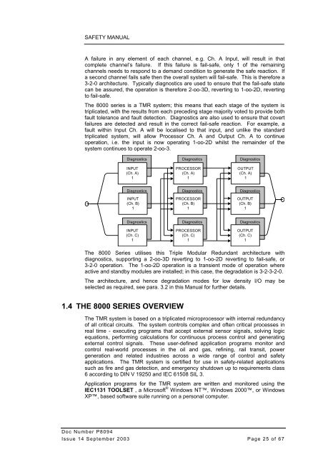
The 8000 series is a TMR system; this means that each stage of the system is<br />
triplicated, with the results from each preceding stage majority voted to provide both<br />
fault tolerance and fault detection. Diagnostics are also used to ensure that covert<br />
failures are detected and result in the correct fail-safe reaction. For example, a<br />
fault within Input Ch. A will be localised to that input, and unlike the standard<br />
triplicated system, will allow Processor Ch. A and Output Ch. A to continue<br />
operation, i.e. the input is now operating 1-oo-2D whilst the remainder of the<br />
system continues to operate 2-oo-3.<br />
Diagnostics<br />
INPUT<br />
(Ch. A)<br />
1<br />
Diagnostics<br />
PROCESSOR<br />
(Ch. A)<br />
1<br />
Diagnostics<br />
OUTPUT<br />
(Ch. A)<br />
1<br />
Diagnostics<br />
INPUT<br />
(Ch. B)<br />
1<br />
Diagnostics<br />
PROCESSOR<br />
(Ch. B)<br />
1<br />
Diagnostics<br />
OUTPUT<br />
(Ch. B)<br />
1<br />
Diagnostics<br />
INPUT<br />
(Ch. C)<br />
1<br />
Diagnostics<br />
PROCESSOR<br />
(Ch. C)<br />
1<br />
Diagnostics<br />
OUTPUT<br />
(Ch. C)<br />
1<br />
The 8000 Series utilises this Triple Modular Redundant architecture with<br />
diagnostics, supporting a 2-oo-3D reverting to 1-oo-2D reverting to fail-safe, or<br />
3-2-0 operation. The 1-oo-2D operation is a transient mode of operation where<br />
active and standby modules are installed; in this case, the degradation is 3-2-3-2-0.<br />
The architecture, and hence degradation modes for low density I/O may be<br />
selected as required, see para. 3.2 in this Manual for further details.<br />
1.4 THE 8000 SERIES OVERVIEW<br />
The TMR system is based on a triplicated microprocessor with internal redundancy<br />
of all critical circuits. The system controls <strong>com</strong>plex and often critical processes in<br />
real time - executing programs that accept external sensor signals, solving logic<br />
equations, performing calculations for continuous process control and generating<br />
external control signals. These user-defined application programs monitor and<br />
control real-world processes in the oil and gas, refining, rail transit, power<br />
generation and related industries across a wide range of control and safety<br />
applications. The TMR system is certified for use in safety-related applications<br />
such as fire and gas detection, and emergency shutdown up to requirements class<br />
6 according to DIN V 19250 and IEC 61508 SIL 3.<br />
Application programs for the TMR system are written and monitored using the<br />
IEC1131 TOOLSET , a Microsoft ® Windows NT, Windows 2000, or Windows<br />
XP, based software suite running on a personal <strong>com</strong>puter.<br />
Doc Number P8094<br />
Issue 14 September 2003 Page 25 of 67


