Marconi Applied Technologies CX1154L Deuterium ... - Alphatron
Marconi Applied Technologies CX1154L Deuterium ... - Alphatron
Marconi Applied Technologies CX1154L Deuterium ... - Alphatron
- No tags were found...

Create successful ePaper yourself
Turn your PDF publications into a flip-book with our unique Google optimized e-Paper software.
MAXIMUM AND MINIMUM RATINGS<br />
(Absolute values)<br />
These ratings cannot necessarily be used simultaneously, and<br />
no individual rating must be exceeded.<br />
Min Typical Max<br />
Anode (Pulse Modulator Service)<br />
Peak forward anode voltage<br />
(see note 3) . . . . . . . ± ± 35 kV<br />
Peak inverse anode voltage<br />
(see note 4) . . . . . . . ± ± 35 kV<br />
Peak anode current . . . . . ± 3.0 ± kA<br />
Peak anode current (pulse repetition<br />
rate limited to 60 pps max) . . ± ± 4.0 kA<br />
Average anode current . . . . ± ± 2.0 A<br />
Rate of rise of anode current<br />
(see notes 5 and 6) . . . . . ± 10 ± kA/ms<br />
Pulse repetition rate . . . . . ± 400 ± pps<br />
Min Max<br />
Anode (Single-Shot or Fault Condition)<br />
DC forward anode voltage . . . . . ± 30 kV<br />
Peak anode current . . . . . . . ± 10 kA<br />
Rate of rise of anode current . . . . . . . see note 5<br />
Total conducted charge:<br />
capacitor discharge . . . . . . ± 0.1 C<br />
power supply follow-on<br />
(see note 7) . . . . . . . . . ± 4 C<br />
Repetition frequency . . . . . . . 1 pulse per 10 s max<br />
Grid 2<br />
Unloaded grid 2 drive pulse voltage<br />
(see note 8) . . . . . . . . . 500 2000 V<br />
Grid 2 pulse duration . . . . . . . 0.5 ± ms<br />
Rate of rise of grid 2 pulse<br />
(see note 6) . . . . . . . . . 10 ± kV/ms<br />
Grid 2 pulse delay . . . . . . . . 0.5 3.0 ms<br />
Peak inverse grid 2 voltage . . . . . ± 450 V<br />
Loaded grid 2 bias voltage . . . . . 0 7150 V<br />
Forward impedance of grid 2<br />
drive circuit . . . . . . . . . 50 500 O<br />
Grid 1 ± Pulsed<br />
Peak grid 1 drive current<br />
(see note 9) . . . . . . . . . 1.0 5.0 A<br />
Unloaded grid 1 drive pulse voltage<br />
(see note 8) . . . . . . . . . 300 1000 V<br />
Grid 1 pulse duration . . . . . . . 2.0 ± ms<br />
Rate of rise of grid 1 pulse (see note 6) . 1.0 ± kV/ms<br />
Peak inverse grid 1 voltage . . . . . ± 450 V<br />
Loaded grid 1 bias voltage . . . . . . . . see note 10<br />
Grid 1 ± DC Primed (See note 10)<br />
DC grid 1 unloaded priming voltage . . 75 150 V<br />
DC grid 1 priming current . . . . . 75 150 mA<br />
Cathode<br />
Heater voltage . . . . . . . . . 6.3 6.8 V<br />
Heating time . . . . . . . . . 15 ± min<br />
Reservoir<br />
Heater voltage (see note 1) . . . . . 5.0 6.0 V<br />
Heating time . . . . . . . . . 15 ± min<br />
Environmental<br />
Ambient temperature . . . . . . 750 +90 8C<br />
Altitude . . . . . . . . . . . ± 3 km<br />
± 10 000 ft<br />
CHARACTERISTICS<br />
Min Typical Max<br />
Critical DC anode voltage for<br />
conduction (see note 11) . . . ± 0.5 1.0 kV<br />
Anode delay time<br />
(see notes 11 and 12) . . . . ± 0.15 0.25 ms<br />
Anode delay time drift<br />
(see notes 11 and 13) . . . . ± 15 50 ns<br />
Time jitter (see note 11) . . . . ± 1.0 5.0 ns<br />
Recovery time . . . . . . . . . see graph on page 5<br />
Cathode heater current<br />
(at 6.3 V) . . . . . . . . 20 22.5 25 A<br />
Reservoir heater current<br />
(at 5.5 V) . . . . . . . . 6.0 7.0 8.0 A<br />
NOTES<br />
1. The reservoir heater must be decoupled with a suitable<br />
capacitor to avoid damage by spike voltages. The recommended<br />
reservoir heater voltage for each individual tube is<br />
stamped on the tube envelope. This recommended value is<br />
determined for operation at the maximum anode voltage<br />
under modulator conditions. For lower voltages and DC<br />
operation the reservoir heater voltage should be changed<br />
to a value consistent with voltage hold-off at the operating<br />
level. Maximum reservoir voltage (i.e. maximum gas<br />
pressure in the tube) is one prerequisite for maximum<br />
thyratron life. The reservoir voltage should be stabilised to<br />
+0.1 V.<br />
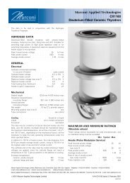
2. The tube must be fitted using its mounting flange.<br />
3. Under resonant charging conditions a maximum anode<br />
voltage of 35 kV is recommended. Using command<br />
charging conditions where the voltage appears at the<br />
anode for only a short time (51 ms), this thyratron may<br />
be operated up to 40 kV.<br />
4. The peak inverse voltage including spike must not exceed<br />
10 kV for the first 125 ms after the anode pulse.<br />
5. In single shot or burst mode, this parameter can exceed<br />
150 kA/ms. The ultimate value which can be attained<br />
depends to a large extent upon the external circuit.<br />
6. This rate of rise refers to that part of the leading edge of<br />
the pulse between 25% and 75% of the pulse amplitude.<br />
7. Under fault conditions, most of the coulombs are often in<br />
the power supply follow-on current, rather than the<br />
storage capacitor discharge.<br />
8. Measured with respect to cathode. Pre-pulsing of grid 1 is<br />
recommended for modulator and high rate of rise of<br />
current applications. The last 0.25 ms of the top of the grid<br />
1 pulse must overlap the corresponding first 0.25 ms of the<br />
top of the delayed grid 2 pulse.<br />
<strong>CX1154L</strong>, page 2<br />
#2000 <strong>Marconi</strong> <strong>Applied</strong> <strong>Technologies</strong>