Marconi Applied Technologies CX1154L Deuterium ... - Alphatron
Marconi Applied Technologies CX1154L Deuterium ... - Alphatron
Marconi Applied Technologies CX1154L Deuterium ... - Alphatron
- No tags were found...

You also want an ePaper? Increase the reach of your titles
YUMPU automatically turns print PDFs into web optimized ePapers that Google loves.
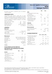
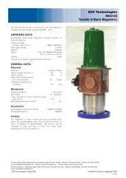
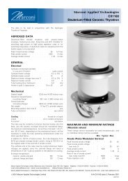
<strong>Marconi</strong> <strong>Applied</strong> <strong>Technologies</strong><br />
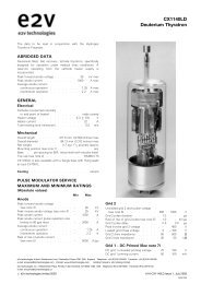
<strong>CX1154L</strong><br />
<strong>Deuterium</strong> Filled Ceramic Thyratron<br />
The data to be read in conjunction with the Hydrogen<br />
Thyratron Preamble.<br />
ABRIDGED DATA<br />
<strong>Deuterium</strong>-filled tetrode thyratron with ceramic/metal<br />
envelope, featuring fast recovery time, low jitter, firing time<br />
and drift. This tube has been developed specifically to give<br />
improved performance over the CX1154 in magnetron and<br />
klystron pulse modulators.<br />
Peak forward anode voltage . . . . . . 35 kV max<br />
Peak anode current . . . . . . . . . 3.0 kA max<br />
Average anode current . . . . . . . . 2.0 A max<br />
GENERAL DATA<br />
Electrical<br />
Cathode (connected internally<br />
to one end of heater) . . . . . . . . oxide coated<br />
Cathode heater voltage . . . . . . . . 6.3 + 0.5 V<br />
7 0.0<br />
Cathode heater current . . . . . . . 22.5 A<br />
Reservoir heater voltage (see note 1) . . . . 5.5 V<br />
Reservoir heater current . . . . . . . . 7.0 A<br />
Tube heating time (minimum) . . . . . 15 min<br />
Anode to grid 2 capacitance . . . 15 to 20 pF<br />
Mechanical<br />
Seated height . . . . . 165.1 mm (6.500 inches) max<br />
Clearance required below<br />
mounting flange . . . . . 38.1 mm (1.500 inches) min<br />
Overall diameter<br />
(mounting flange) . . . 111.1 mm (4.375 inches) nom<br />
Net weight . . . . . . . . 1.8 kg (4 pounds) approx<br />
Mounting position (see note 2) . . . . . . . . . any<br />
Tube connections . . . . . . . . . . . see outline<br />
Cooling . . . . . . . . . . . liquid or forced-air<br />
Liquid . . . . . . . . . . oil or coolant immersion<br />
Forced-air . . . . . . . . . . . . . . see below<br />
Cooling by oil or coolant immersion is preferred in view of the<br />
high voltages present. Further information is contained in the<br />
relevant section of the Preamble.<br />
The tube may be cooled by forced-air directed mainly onto the<br />
base, and the metal/ceramic envelope should be maintained<br />
below the maximum rated temperature. An air flow of at least<br />
2.83 m 3 /min (100 ft 3 /min), depending on the mechanical<br />
layout, will be necessary to keep the tube operating<br />
temperatures under the limits specified below.<br />
In addition to 200 W of heater power, the tube dissipates from<br />
100 W per ampere average anode current, rising to 300 W/A<br />
at the highest rates of rise and fall of anode current.<br />
The cathode end of the tube must be cooled whenever heater<br />
voltages are applied, since the cathode flange will reach a<br />
temperature of 120 8C above ambient in the absence of cooling.<br />
Envelope temperature:<br />
ceramic, anode and grids . . . . . . 150 8C max<br />
cathode flange and base . . . . . . 120 8C max<br />
<strong>Marconi</strong> <strong>Applied</strong> <strong>Technologies</strong> Limited, Waterhouse Lane, Chelmsford, Essex CM1 2QU England Telephone: +44 (0)1245 493493 Facsimile: +44 (0)1245 492492<br />
e-mail: info@eev.com Internet: www.marconitech.com Holding Company: <strong>Marconi</strong> p.l.c.<br />
<strong>Marconi</strong> <strong>Applied</strong> <strong>Technologies</strong> Inc. 4 Westchester Plaza, PO Box 1482, Elmsford, NY10523-1482 USA Telephone: (914) 592-6050 Facsimile: (914) 592-5148 e-mail: info@eevinc.com<br />
#2000 <strong>Marconi</strong> <strong>Applied</strong> <strong>Technologies</strong> Limited A1A-<strong>CX1154L</strong> Issue 2, March 2000<br />
930/54
MAXIMUM AND MINIMUM RATINGS<br />
(Absolute values)<br />
These ratings cannot necessarily be used simultaneously, and<br />
no individual rating must be exceeded.<br />
Min Typical Max<br />
Anode (Pulse Modulator Service)<br />
Peak forward anode voltage<br />
(see note 3) . . . . . . . ± ± 35 kV<br />
Peak inverse anode voltage<br />
(see note 4) . . . . . . . ± ± 35 kV<br />
Peak anode current . . . . . ± 3.0 ± kA<br />
Peak anode current (pulse repetition<br />
rate limited to 60 pps max) . . ± ± 4.0 kA<br />
Average anode current . . . . ± ± 2.0 A<br />
Rate of rise of anode current<br />
(see notes 5 and 6) . . . . . ± 10 ± kA/ms<br />
Pulse repetition rate . . . . . ± 400 ± pps<br />
Min Max<br />
Anode (Single-Shot or Fault Condition)<br />
DC forward anode voltage . . . . . ± 30 kV<br />
Peak anode current . . . . . . . ± 10 kA<br />
Rate of rise of anode current . . . . . . . see note 5<br />
Total conducted charge:<br />
capacitor discharge . . . . . . ± 0.1 C<br />
power supply follow-on<br />
(see note 7) . . . . . . . . . ± 4 C<br />
Repetition frequency . . . . . . . 1 pulse per 10 s max<br />
Grid 2<br />
Unloaded grid 2 drive pulse voltage<br />
(see note 8) . . . . . . . . . 500 2000 V<br />
Grid 2 pulse duration . . . . . . . 0.5 ± ms<br />
Rate of rise of grid 2 pulse<br />
(see note 6) . . . . . . . . . 10 ± kV/ms<br />
Grid 2 pulse delay . . . . . . . . 0.5 3.0 ms<br />
Peak inverse grid 2 voltage . . . . . ± 450 V<br />
Loaded grid 2 bias voltage . . . . . 0 7150 V<br />
Forward impedance of grid 2<br />
drive circuit . . . . . . . . . 50 500 O<br />
Grid 1 ± Pulsed<br />
Peak grid 1 drive current<br />
(see note 9) . . . . . . . . . 1.0 5.0 A<br />
Unloaded grid 1 drive pulse voltage<br />
(see note 8) . . . . . . . . . 300 1000 V<br />
Grid 1 pulse duration . . . . . . . 2.0 ± ms<br />
Rate of rise of grid 1 pulse (see note 6) . 1.0 ± kV/ms<br />
Peak inverse grid 1 voltage . . . . . ± 450 V<br />
Loaded grid 1 bias voltage . . . . . . . . see note 10<br />
Grid 1 ± DC Primed (See note 10)<br />
DC grid 1 unloaded priming voltage . . 75 150 V<br />
DC grid 1 priming current . . . . . 75 150 mA<br />
Cathode<br />
Heater voltage . . . . . . . . . 6.3 6.8 V<br />
Heating time . . . . . . . . . 15 ± min<br />
Reservoir<br />
Heater voltage (see note 1) . . . . . 5.0 6.0 V<br />
Heating time . . . . . . . . . 15 ± min<br />
Environmental<br />
Ambient temperature . . . . . . 750 +90 8C<br />
Altitude . . . . . . . . . . . ± 3 km<br />
± 10 000 ft<br />
CHARACTERISTICS<br />
Min Typical Max<br />
Critical DC anode voltage for<br />
conduction (see note 11) . . . ± 0.5 1.0 kV<br />
Anode delay time<br />
(see notes 11 and 12) . . . . ± 0.15 0.25 ms<br />
Anode delay time drift<br />
(see notes 11 and 13) . . . . ± 15 50 ns<br />
Time jitter (see note 11) . . . . ± 1.0 5.0 ns<br />
Recovery time . . . . . . . . . see graph on page 5<br />
Cathode heater current<br />
(at 6.3 V) . . . . . . . . 20 22.5 25 A<br />
Reservoir heater current<br />
(at 5.5 V) . . . . . . . . 6.0 7.0 8.0 A<br />
NOTES<br />
1. The reservoir heater must be decoupled with a suitable<br />
capacitor to avoid damage by spike voltages. The recommended<br />
reservoir heater voltage for each individual tube is<br />
stamped on the tube envelope. This recommended value is<br />
determined for operation at the maximum anode voltage<br />
under modulator conditions. For lower voltages and DC<br />
operation the reservoir heater voltage should be changed<br />
to a value consistent with voltage hold-off at the operating<br />
level. Maximum reservoir voltage (i.e. maximum gas<br />
pressure in the tube) is one prerequisite for maximum<br />
thyratron life. The reservoir voltage should be stabilised to<br />
+0.1 V.<br />
2. The tube must be fitted using its mounting flange.<br />
3. Under resonant charging conditions a maximum anode<br />
voltage of 35 kV is recommended. Using command<br />
charging conditions where the voltage appears at the<br />
anode for only a short time (51 ms), this thyratron may<br />
be operated up to 40 kV.<br />
4. The peak inverse voltage including spike must not exceed<br />
10 kV for the first 125 ms after the anode pulse.<br />
5. In single shot or burst mode, this parameter can exceed<br />
150 kA/ms. The ultimate value which can be attained<br />
depends to a large extent upon the external circuit.<br />
6. This rate of rise refers to that part of the leading edge of<br />
the pulse between 25% and 75% of the pulse amplitude.<br />
7. Under fault conditions, most of the coulombs are often in<br />
the power supply follow-on current, rather than the<br />
storage capacitor discharge.<br />
8. Measured with respect to cathode. Pre-pulsing of grid 1 is<br />
recommended for modulator and high rate of rise of<br />
current applications. The last 0.25 ms of the top of the grid<br />
1 pulse must overlap the corresponding first 0.25 ms of the<br />
top of the delayed grid 2 pulse.<br />
<strong>CX1154L</strong>, page 2<br />
#2000 <strong>Marconi</strong> <strong>Applied</strong> <strong>Technologies</strong>
9. The higher grid 1 is pulsed, the larger must the grid 2<br />
negative bias be, to prevent the tube firing on the grid 1<br />
pulse.<br />
10. DC negative bias voltages must not be applied to grid 1.<br />
When grid 1 is pulse driven, the potential of grid 1 may<br />
vary between 710 and +5 V with respect to cathode<br />
potential during the period between the completion of<br />
recovery and the commencement of the succeeding grid<br />
pulse.<br />
11. Typical figures are obtained on test using conditions of<br />
minimum grid drive. Improved performance can be expected<br />
by increasing grid drive.<br />
12. The time interval between the instant at which the rising<br />
unloaded grid 2 pulse reaches 25% of its pulse amplitude<br />
and the instant when anode conduction takes place.<br />
13. The drift in delay time over a period from 10 seconds to 10<br />
minutes after reaching full voltage.<br />
HEALTH AND SAFETY HAZARDS<br />
<strong>Marconi</strong> <strong>Applied</strong> <strong>Technologies</strong> hydrogen thyratrons are safe to<br />
handle and operate, provided that the relevant precautions<br />
stated herein are observed. <strong>Marconi</strong> <strong>Applied</strong> <strong>Technologies</strong> does<br />
not accept responsibility for damage or injury resulting from the<br />
use of electronic devices it produces. Equipment manufacturers<br />
and users must ensure that adequate precautions are taken.<br />
Appropriate warning labels and notices must be provided on<br />
equipments incorporating <strong>Marconi</strong> <strong>Applied</strong> <strong>Technologies</strong><br />
devices and in operating manuals.<br />
High Voltage<br />
Equipment must be designed so that personnel cannot come<br />
into contact with high voltage circuits. All high voltage circuits<br />
and terminals must be enclosed and fail-safe interlock switches<br />
must be fitted to disconnect the primary power supply and<br />
discharge all high voltage capacitors and other stored charges<br />
before allowing access. Interlock switches must not be<br />
bypassed to allow operation with access doors open.<br />
SCHEMATIC DIAGRAM<br />
7543<br />
X-Ray Radiation<br />
All high voltage devices produce X-rays during operation and<br />
may require shielding. The X-ray radiation from hydrogen<br />
thyratrons is usually reduced to a safe level by enclosing the<br />
equipment or shielding the thyratron with at least 1 / 16 -inch (1.6<br />
mm) thick steel panels.<br />
Users and equipment manufacturers must check the<br />
radiation level under their maximum operating conditions.<br />
GRID 2 DELAYED<br />
WITH RESPECT TO GRID 1<br />
GRID 2 VOLTAGE<br />
500 ± 2000 V,<br />
1 ms<br />
G2<br />
R 2<br />
0<br />
NEGATIVE BIAS VOLTAGE<br />
CATHODE<br />
HEATER<br />
SUPPLY<br />
C 1<br />
G1<br />
R 1<br />
GRID 1 CURRENT<br />
1.0 A, 2 ms<br />
0.5 ms MIN<br />
GRID 1/GRID 2 DELAY<br />
RESERVOIR<br />
HEATER<br />
SUPPLY<br />
(VARIABLE)<br />
C 2<br />
RECOMMENDED GRID, CATHODE AND RESERVOIR HEATER CONNECTIONS<br />
R 1 = Grid 1 series resistor. 12 W vitreous enamelled wirewound is recommended, of a total impedance to match the<br />
grid 1 drive pulse circuit.<br />
R 2 = Grid 2 series resistor. 12 W vitreous enamelled wirewound is recommended, of an impedance to match the grid 2<br />
drive pulse circuit.<br />
C 1 , C 2 7 reservoir protection capacitors with a voltage rating 5500 V;<br />
C 1 = 1000 pF low inductance (e.g. ceramic),<br />
C 2 = 1 mF (e.g. polycarbonate or polypropylene).<br />
Components R 1 , R 2 , C 1 and C 2 should be mounted as close to the tube as possible.<br />
#2000 <strong>Marconi</strong> <strong>Applied</strong> <strong>Technologies</strong> <strong>CX1154L</strong>, page 3
OUTLINE<br />
(All dimensions without limits are nominal)<br />
2397C<br />
1C<br />
ANODE CONNECTION FITTED<br />
WITH 1 / 4 -20 UNC SCREW<br />
L<br />
A<br />
GRID 2 CONNECTION<br />
FITTED WITH<br />
8-32 UNC SCREW<br />
Ref Millimetres Inches<br />
E<br />
SEE NOTE 2<br />
D<br />
1F<br />
SEE NOTE 3<br />
MOUNTING FLANGE<br />
SEE NOTE 1<br />
A 165.1 max 6.500 max<br />
B 111.13 4.375<br />
C 101.6 4.000<br />
D 2.54 0.100<br />
E 50.8 min 2.000 min<br />
F 69.85 max 2.750 max<br />
G 190.5 min 7.500 min<br />
H 6.35 0.250<br />
J 6.50 0.256<br />
K 95.25 3.750<br />
L 85.73 3.375<br />
Inch dimensions have been derived from millimetres.<br />
1B<br />
GRID 1 LEAD (GREEN)<br />
G LONG, TAG TO SUIT 1H<br />
6 HOLES 1J<br />
EQUISPACED ON K PCD<br />
Outline Notes<br />
1. The mounting flange is the connection for the<br />
cathode, cathode heater return and reservoir<br />
heater return.<br />
2. A minimum clearance of 38.1 mm (1.500 inches)<br />
must be allowed below the mounting flange.<br />
3. The recommended mounting hole is 73.0 mm<br />
(2.875 inches) diameter.<br />
CATHODE HEATER LEAD (YELLOW)<br />
G LONG, TAG TO SUIT 1H<br />
RESERVOIR HEATER LEAD (RED)<br />
G LONG, TAG TO SUIT 1H<br />
<strong>CX1154L</strong>, page 4<br />
#2000 <strong>Marconi</strong> <strong>Applied</strong> <strong>Technologies</strong>
TYPICAL RECOVERY CHARACTERISTICS (Reservoir voltage 5.5 V)<br />
50<br />
7542<br />
GRID 2 VOLTAGE 0 V<br />
PEAK ANODE CURRENT 1000 A<br />
RE-APPLIED ANODE VOLTAGE 1 kV<br />
45<br />
40<br />
712.5<br />
725<br />
35<br />
30<br />
25<br />
750<br />
7100<br />
20<br />
15<br />
RECOVERY TIME (ms)<br />
10<br />
5<br />
0<br />
100 500 1000 5000 10 000 50 000<br />
GRID RECOVERY IMPEDANCE (O)<br />
Whilst <strong>Marconi</strong> <strong>Applied</strong> <strong>Technologies</strong> has taken care to ensure the accuracy of the information contained herein it accepts no responsibility for the consequences of any<br />
use thereof and also reserves the right to change the specification of goods without notice. <strong>Marconi</strong> <strong>Applied</strong> <strong>Technologies</strong> accepts no liability beyond that set out in its<br />
standard conditions of sale in respect of infringement of third party patents arising from the use of tubes or other devices in accordance with information contained herein.<br />
#2000 <strong>Marconi</strong> <strong>Applied</strong> <strong>Technologies</strong> Printed in England<br />
<strong>CX1154L</strong>, page 5