Pressure Control Valves - Mankenberg
Pressure Control Valves - Mankenberg
Pressure Control Valves - Mankenberg

Create successful ePaper yourself
Turn your PDF publications into a flip-book with our unique Google optimized e-Paper software.
Page No. DM 462/2.1.116.1 - Standing 15.11.2011 MANKENBERG GmbH | Spenglerstraße 99 | D-23556 Lübeck www.mankenberg.de | Tel. +49 (0) 451 - 8 79 75 0<br />
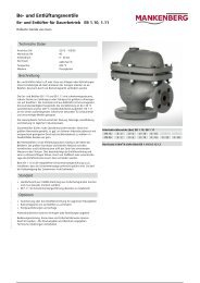
<strong>Pressure</strong> <strong>Control</strong> <strong>Valves</strong><br />
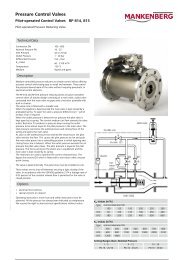
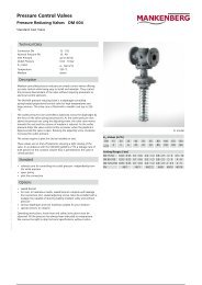
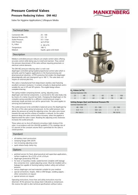
<strong>Pressure</strong> Reducing <strong>Valves</strong> DM 462<br />
Valve for Hygiene Applications | Ultrapure Media<br />
Technical Data<br />
Connection DN 25 - 100<br />
Nominal <strong>Pressure</strong> PN 2.5 - 10<br />
Outlet <strong>Pressure</strong> 0.3 - 5 bar<br />
Inlet <strong>Pressure</strong> up to 8 bar<br />
K vs-Value<br />
4 - 80 m 3 /h<br />
Temperature 180 °C<br />
Medium liquids, gases and steam<br />
Description<br />
Medium-controlled pressure reducers are simple control valves offering<br />
accurate control while being easy to install and maintain. They control<br />
the pressure downstream of the valve without requiring pneumatic or<br />
electrical control elements.<br />
The DM 462 pressure reducing valve is a twin seat<br />
diaphragm-controlled spring-loaded proportional control valve which is<br />
primarily used for hygienic applications in the food processing and<br />
pharmaceutical industries. A PTFE protective foil renders the diaphragm<br />
physiologically safe and steamproof up to 180 °C. The valve does not<br />
require an external pilot line.<br />
This valve is manufactured from deep-drawn stainless steel featuring<br />
excellent corrosion resistance. It contains virtually no dead pockets and is<br />
suitable for use in CIP and SIP systems. The angled design allows<br />
complete draining.<br />
The spring module comprising bonnet, spring, adjusting screw,<br />
diaphragm and internal components, is connected to the valve body only<br />
by means of a clamp ring and two bolts. Changing the diaphragm or the<br />
complete spring assembly for a different control pressure range is<br />
extremely simple and does not call for special tools. The same applies to<br />
servicing and maintenance.<br />
The outlet pressure to be controlled is balanced across the diaphragm by<br />
the force of the valve spring (set pressure). As the outlet pressure rises<br />
above the pressure set using the adjusting screw, the valve cone moves<br />
towards the seat and the volume of medium is reduced. As the outlet<br />
pressure drops the valve control orifice increases; when the pipeline is<br />
depressurised the valve is open. Rotating the adjusting screw clockwise<br />
increases the outlet pressure.<br />
These valves are no shut-off elements ensuring a tight closing of the<br />
valve. In accordance with the VDI/VDE guideline 2174 a leakage rate of<br />
0.5 percent of the constant volume flow is permitted for the valve in<br />
closed position..<br />
Standard<br />
» all stainless steel construction<br />
» clamping flanges DIN 32676<br />
» non increasing adjusting screw<br />
» quick-release body clamp ring<br />
Options<br />
» polished version for food, pharmaceutical and superclean applications,<br />
surface roughness: Ra ≤ 0.25/ ≤ 0.4/ ≤ 0.8 µm<br />
» diaphragm protectd by PTFE foil<br />
» for toxic or hazardous media: sealed bonnet complete with leakage<br />
line connection (incl. sealed adjusting screw). Must be installed with a<br />
leakage line capable of draining leaking medium safely and without<br />
pressure<br />
» various diaphragm and seal materials suitable for your medium<br />
» special connections: Aseptic, ANSI or DIN flanges, welding spigots;<br />
other connections on request<br />
» special versions on request<br />
Operating instructions, know how and safety instructions must be<br />
observed. All the pressure has always been indicated as overpressure.<br />
We reserve the right to alter technical specifications without notice.<br />
K vs-Values [m 3 /h]<br />
nominal diameter DN<br />
25 40 50 65 80 100<br />
4 22 22 60 70 80<br />
Setting Ranges [bar] and Nominal <strong>Pressure</strong> PN<br />
nominal diameter DN<br />
40 - 100 25 - 100 25 - 100<br />
0.3 - 1.1 0.8 - 2.5 2 - 5<br />
PN 10/2.5 PN 10/6 PN 10/10
Page No. DM 462/2.1.116.2 - Standing 15.11.2011 MANKENBERG GmbH | Spenglerstraße 99 | D-23556 Lübeck www.mankenberg.de | Tel. +49 (0) 451 - 8 79 75 0<br />
<strong>Pressure</strong> <strong>Control</strong> <strong>Valves</strong><br />
<strong>Pressure</strong> Reducing <strong>Valves</strong> DM 462<br />
Valve for Hygiene Applications | Ultrapure Media<br />
Materials<br />
Temperature 130 °C 180 °C<br />
Body, Spring, Internals SST 316L SST 316L<br />
Valve Seal EPDM FEPM<br />
Spring CrNi-steel CrNi-steel<br />
Diaphragm EPDM FPM<br />
Protection Foil for Diaphragm Option PTFE<br />
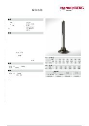
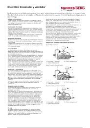
Dimensions [mm]<br />
size nominal diameter DN (clamping flanges)<br />
25 40 50 65 80 100<br />
AE 100 115 125 175 175 175<br />
C 205 230 230 515 515 515<br />
D 138 200 200 240 240 240<br />
Weights [kg]<br />
nominal diameter DN (clamping flanges)<br />
25 40 50 65 80 100<br />
2.5 6.5 6.5 26 26 26<br />
Special designs on request.<br />
The pressure has always been indicated as overpressure.<br />
<strong>Mankenberg</strong> reserves the right to alter or improve the designs or<br />
specifications of the products described herein without notice.<br />
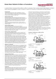
Dimensional Drawing<br />
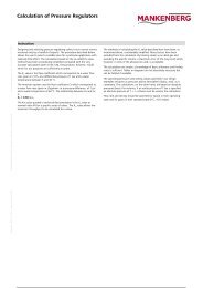
Recommended Installation<br />
1 Strainer 5 <strong>Pressure</strong> Gauge<br />
2 Shutoff valves 6 Leakage Line G 1/8<br />
3 <strong>Pressure</strong> Reducer (option)<br />
4 Safety Valve<br />
use MANKENBERG-Products