High Power Capacitors for Power Electronics - AVX
High Power Capacitors for Power Electronics - AVX
High Power Capacitors for Power Electronics - AVX
- No tags were found...
Create successful ePaper yourself
Turn your PDF publications into a flip-book with our unique Google optimized e-Paper software.
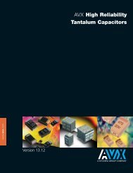
<strong>AVX</strong> <strong>High</strong> <strong>Power</strong> <strong>Capacitors</strong><br />
For <strong>Power</strong> <strong>Electronics</strong><br />
www.avx.com<br />
Version 9.5
Contents<br />
<strong>Capacitors</strong> <strong>for</strong> <strong>High</strong> <strong>Power</strong> <strong>Electronics</strong><br />
FIM PRODUCTS. . . . . . . . . . . . . . . . . . . . . . . . . . . . . . . . . . . . . . . . . . . . . . . . . . . . . . . . . . . . . 2-10<br />
Technology. . . . . . . . . . . . . . . . . . . . . . . . . . . . . . . . . . . . . . . . . . . . . . . . . . . . . . . . . . . . . . . . 2<br />
Characteristics . . . . . . . . . . . . . . . . . . . . . . . . . . . . . . . . . . . . . . . . . . . . . . . . . . . . . . . . . . . 3<br />
General Description. . . . . . . . . . . . . . . . . . . . . . . . . . . . . . . . . . . . . . . . . . . . . . . . . . . 4-10<br />
CAPAFIM PRODUCTS . . . . . . . . . . . . . . . . . . . . . . . . . . . . . . . . . . . . . . . . . . . . . . . . . . . . . 11-14<br />
Table of Values . . . . . . . . . . . . . . . . . . . . . . . . . . . . . . . . . . . . . . . . . . . . . . . . . . . . . . . 12-13<br />
Mechanical Design . . . . . . . . . . . . . . . . . . . . . . . . . . . . . . . . . . . . . . . . . . . . . . . . . . . . . . 14<br />
TRAFIM PRODUCTS . . . . . . . . . . . . . . . . . . . . . . . . . . . . . . . . . . . . . . . . . . . . . . . . . . . . . . . 15-22<br />
Table of Values . . . . . . . . . . . . . . . . . . . . . . . . . . . . . . . . . . . . . . . . . . . . . . . . . . . . . . . 17-20<br />
Mechanical Design . . . . . . . . . . . . . . . . . . . . . . . . . . . . . . . . . . . . . . . . . . . . . . . . . . . . . . 21<br />
Terminals and Connections . . . . . . . . . . . . . . . . . . . . . . . . . . . . . . . . . . . . . . . . . . . . . 22<br />
FILFIM PRODUCTS . . . . . . . . . . . . . . . . . . . . . . . . . . . . . . . . . . . . . . . . . . . . . . . . . . . . . . . . 23-27<br />
Table of Values . . . . . . . . . . . . . . . . . . . . . . . . . . . . . . . . . . . . . . . . . . . . . . . . . . . . . . . 25-26<br />
Mechanical Design . . . . . . . . . . . . . . . . . . . . . . . . . . . . . . . . . . . . . . . . . . . . . . . . . . . . . . 27<br />
CALCULATION FORM. . . . . . . . . . . . . . . . . . . . . . . . . . . . . . . . . . . . . . . . . . . . . . . . . . . . . . . . . 28<br />
DISFIM PRODUCTS . . . . . . . . . . . . . . . . . . . . . . . . . . . . . . . . . . . . . . . . . . . . . . . . . . . . . . . . . . . 29<br />
GUIDE FOR CUSTOMER’S SPECIFIC REQUIREMENTS . . . . . . . . . . . . . . . . . . . . . 30<br />
<strong>AVX</strong> PRODUCTS LISTING . . . . . . . . . . . . . . . . . . . . . . . . . . . . . . . . . . . . . . . . . . . . . . . . . . . . . 31<br />
1
FIM Products<br />
FIM Technology<br />
TPC (acquired by <strong>AVX</strong> Corporation in 1998) is at the <strong>for</strong>efront of high<br />
per<strong>for</strong>mance film capacitor technology improvements <strong>for</strong> 30 years.<br />
In 1979, we developed CONTROLLED SELF-HEALING technology<br />
specifically to enhance the per<strong>for</strong>mance of film power capacitors.<br />
This enables the capacitor to continue to function without catastrophic<br />
failure by insulating the weak points of the dielectric material. During<br />
operation, the capacitor behaves like a battery. It will consume<br />
capacitance via the gradual breakdown of individual cells until it<br />
decreases down to 2% of the original value.<br />
Since 1988, FIM technology launching year, we continuously improve<br />
per<strong>for</strong>mances to meet DC filtering power applications.<br />
FIM technology with polypropylene Film, vegetable oil Impregnated<br />
and aluminium Metallization combines totally safe behavior and high<br />
energy density.<br />
FIM technology is available in CAPAFIM, TRAFIM and FILFIM ranges<br />
<strong>for</strong> DC filtering applications.<br />
Also available in DISFIM range <strong>for</strong> energy storage and discharge<br />
applications.<br />
2
FIM Products<br />
Characteristics<br />
ELECTRICAL CHARACTERISTICS FOR DC FILTERING<br />
C n Capacitance<br />
V n Rated DC voltage<br />
V w Working voltage<br />
V r Ripple voltage<br />
V I Insulation voltage<br />
L s Stray inductance<br />
R s Capacitor series resistance<br />
tan δ Tangent of loss angle<br />
I rms Working current<br />
I max Maximum current<br />
Nominal value of the capacitance measured at θ amb =25±10°C.<br />
Maximum operating peak voltage of either polarity (non-reversing type<br />
wave<strong>for</strong>m), <strong>for</strong> which the capacitor has been designed <strong>for</strong> continuous<br />
operation.<br />
Value of the maximum operating recurrent voltage <strong>for</strong> a given hot spot<br />
temperature and an expected lifetime.<br />
Peak-to-peak alternating component of the unidirectional voltage.<br />
Rms rated value of the insulation voltage of capacitive elements and<br />
terminals to case.<br />
Capacitor series self-inductance.<br />
Capacitor series resistance due to galvanic circuit.<br />
Ratio between the equivalent series resistance and the capacitive<br />
reactance of a capacitor at a specified sinusoidal alternating voltage,<br />
frequency and temperature.<br />
Rms current value <strong>for</strong> continuous operation.<br />
Maximum Rms current value <strong>for</strong> continuous operation.<br />
THERMAL CHARACTERISTICS<br />
θ amb (°C) Cooling air temperature<br />
θ HS (°C) Hot spot temperature<br />
θ (°C) Operating temperature<br />
θ min (°C) Minimum operating temperature<br />
θ max (°C) Maximum operating temperature<br />
Temperature of the cooling air measured at the hottest position of the capacitor,<br />
under steady-state conditions, midway between two units. NOTE If only one unit is<br />
involved, it is the temperature measured at a point approximately 0.1 m away from<br />
the capacitor container and at two-thirds of the height from its base.<br />
<strong>High</strong>est temperature obtained inside the case of the capacitor in thermal equilibrium.<br />
Temperature of the hottest point on the case of the capacitor in thermal equilibrium.<br />
Lowest temperature of the dielectric at which the capacitor may be energized.<br />
<strong>High</strong>est temperature of the case at which the capacitor may be operated.<br />
3
FIM Products<br />
General Description<br />
Three series, <strong>for</strong> DC filtering applications, are proposed with nominal voltage from 1200V up to 56kV.<br />
CAPAFIM<br />
DC filtering application up to 3.9kV<br />
Capacitance up to 1620µF<br />
TRAFIM<br />
DC filtering application up to 6kV<br />
Capacitance up to 16100µF<br />
• Standard shape base 340x165<br />
• Book shape base 340x117 which allows:<br />
Lower thermal resistance<br />
Lower serial resistance<br />
<strong>High</strong>er Rms current capability<br />
<strong>High</strong>er thermal exchange<br />
Lower stray inductance<br />
FILFIM<br />
<strong>High</strong> voltage DC filtering available up to 100kV on specific design<br />
Capacitance up to 612µF<br />
For any specific request about capacitance value, voltage, size or shape, contact your <strong>AVX</strong> local representative request by<br />
using the <strong>for</strong>m on page 30.<br />
STANDARDS<br />
IEC61071<br />
IEC61881<br />
IEC61373<br />
IEC60068<br />
NFF16-101<br />
NFF16-102<br />
<strong>Capacitors</strong> <strong>for</strong> power electronics<br />
<strong>Capacitors</strong> <strong>for</strong> power electronics, railway applications, rolling stock equipment<br />
Railway applications, rolling stock equipment, shock and vibration tests<br />
Environmental testing<br />
Railway rolling stock, fire behavior<br />
Railway rolling stock, fire behavior<br />
4
FIM Products<br />
General Description<br />
LIFETIME EXPECTANCY VS HOT SPOT TEMPERATURE AND VOLTAGE<br />
1.7<br />
1.6<br />
1.5<br />
1.4<br />
HS = 50°C<br />
Vw/Vn<br />
1.3<br />
1.2<br />
HS = 70°C<br />
1.1<br />
1<br />
0.9<br />
HS = 85°C<br />
HS = 80°C<br />
0.8<br />
100 1000 10000 100000 1000000<br />
Lifetime Expectancy (hours)<br />
60<br />
TANGENT OF LOSS ANGLE VS FREQUENCY<br />
50<br />
tgδ (10e -4 )<br />
40<br />
30<br />
20<br />
Typical Curve @ 1V/25ºC<br />
10<br />
0<br />
10 100 1000<br />
f(Hz)<br />
5
FIM Products<br />
General Description<br />
TANGENT OF LOSS ANGLE VS TEMPERATURE<br />
30<br />
25<br />
20<br />
tgδ (10e -4 )<br />
15<br />
10<br />
Typical Curve @ 50Hz on Schering Bridge<br />
5<br />
0<br />
0 10 20 30 40 50 60 70 80<br />
(ºC)<br />
ΔC/C VS HOT SPOT TEMPERATURE<br />
4<br />
ΔC/C(%)<br />
3<br />
2<br />
Typical Curve @ 1V/100Hz<br />
1<br />
(ºC)<br />
0<br />
-55 -35 -15 5 25 45 65 85<br />
-1<br />
-2<br />
-3<br />
-4<br />
6
FIM Products<br />
General Description<br />
DIMENSIONS<br />
Dimensions are indicated in the value tables as well as the<br />
weight.<br />
Dimensional tolerances are:<br />
H ± 3mm, W ± 3mm<br />
Initially, the large faces of the capacitor may be slightly<br />
convex. At delivery the maximum width is:<br />
W’max = W +15mm<br />
Standard material is stainless steel. Aluminum is available <strong>for</strong><br />
specific requirement to reduce the weight or induction effect.<br />
MOUNTING<br />
Vertical mounting is the preferred and horizontal is<br />
acceptable. Please contact <strong>AVX</strong> <strong>for</strong> up-side down mounting<br />
configuration.<br />
HANDLING<br />
When unpacking, it is important that no mechanical shocks<br />
occur that might de<strong>for</strong>m the cans and damage the output<br />
connection.<br />
The capacitors include, unless otherwise specified, one or<br />
several gripping elements (mass screws, jack rings or other<br />
hoisting devices); they should be exclusively handled by<br />
means of these elements.<br />
In no case should the electrical output terminals be<br />
used to lift the capacitor.<br />
The grounding wire should be kept in place until the<br />
capacitor is mounted.<br />
ASSEMBLY AND INSTALLATION<br />
To check <strong>for</strong> the absence of excessive mechanical<br />
stresses.<br />
The mechanical stresses in assembly should remain compatible<br />
with the characteristics of the capacitor.<br />
The method of mounting should not lead to the de<strong>for</strong>mation<br />
of the capacitor case.<br />
Tightening torques are given below:<br />
Output through threaded connections:<br />
max = 25 N-m<br />
Mechanical mounting<br />
Moreover vertical position is the preferential one and horizontal<br />
is accepted.<br />
In order to enable air convection, it is necessary to maintain at<br />
least 40mm between the large faces of adjacent capacitors.<br />
Connections<br />
They should not induce any <strong>for</strong>ce on the output terminals.<br />
Flexible connections should be used (braided or thin metal).<br />
The cross section should not be less than:<br />
S = 0.2 x I max where S (mm 2 ) and I max (A)<br />
The skin effect, which occurs vs frequency, must also be<br />
taken into account.<br />
MARKING<br />
The label is usually located 50mm from the top of the case<br />
and centered to the length:<br />
TPC or <strong>AVX</strong> Logo<br />
Test voltage between<br />
Part number<br />
terminals and case<br />
Capacitance and tolerance Batch and serial number<br />
Rated voltage in clear<br />
Date of manufacture<br />
SAFETY<br />
The FIM technology provides excellent safety; there is no risk<br />
of explosion in case of defect throughout the life of the<br />
capacitor. This explains why there is no need to equip these<br />
capacitors with pressure switch. Rapeseed oil is not explosive<br />
or flammable at normal conditions, there<strong>for</strong>e capacitors can be<br />
transported without being subjected to safety rules. Rapeseed<br />
oil flash point is about 317°C and the polypropylene flash point<br />
is near 300°C, so the melting certifies a temperature of security<br />
above 300°C.<br />
In case of fire above this temperature, it is recommended<br />
to use dust or CO 2 . The use of water is contra-indicated. The<br />
possible rejected products during fire are CO 2 , H 2 O, CO (in<br />
case of non-complete combustion), Hydrocarbons and<br />
some other gases. Carrying mask is required <strong>for</strong> protection.<br />
OIL<br />
The only impregnant used in TRAFIM capacitors is rapeseed<br />
oil (otherwise known as Canola oil) and then is fully environmentally<br />
compatible. It does not emit toxic or carcinogenic<br />
gases, nor is it harmful to soil, water or humans in the event<br />
of accidental spillages. As a natural product derived from<br />
foodstuff, it is even edible.<br />
Of all the vegetable oils, rapeseed oil has one of the best<br />
thermal stabilities and lowest acidity levels.<br />
NON-TOXIC COMPOSITION<br />
Our capacitors are free of:<br />
Arsenic, Asbestos, Beryllium, Brominated flame retardants<br />
(PBB and PBDE), Cadmium, CFC, HCFC, Cobalt,<br />
Formaldehyde, Halon, Isocyanatos, Mercury, Nickel PCB,<br />
PCT, Polyaromatic Hydrocarbons (PAH), Phtalates, PVC,<br />
PTFE and Thirams.<br />
Lead is only found in soldering (<strong>for</strong> approximately 0.3% of the<br />
capacitor weight).<br />
Free of SF6.<br />
CALORIFIC VALUE<br />
A <strong>for</strong>mula that gives the calorific value of a standard TRAFIM<br />
capacitor is:<br />
CV (MJ) = L x [4 x 10 -5 x W x H - 1.3 x 10 -5 x H + 8 x<br />
10 -4 x W + 4.55 x 10 -2 ] + 3.75 x N<br />
where H, L, W, are Height, Length and Width in millimeters,<br />
and N is the number of terminals.<br />
DESTROYING CAPACITORS<br />
The destruction of the capacitors are subject to the laws in<br />
<strong>for</strong>ce in each country.<br />
In practice, today, please contact <strong>AVX</strong> <strong>for</strong> a list of companies<br />
who can take charge of the products to be destroyed.<br />
7
FIM Products<br />
General Description<br />
CAPACITOR DESIGN<br />
The capacitor lifetime depends on the working voltage and the hot spot temperature.<br />
Our caps are designed <strong>for</strong> 100000 hours lifetime at nominal voltage and 70°C hot spot temperature. According to your operating<br />
conditions, you will need to calculate the hot spot temperature, and deduce from this calculation if the lifetime obtained<br />
can suit your application.<br />
1 According to the tables, you should find a capacitor<br />
with required capacitance C n and voltage V n with<br />
V n >V w .<br />
2100<br />
Calculate the maximum ripple voltage allowed <strong>for</strong> the<br />
chosen cap and check if V r
FIM Products<br />
General Description<br />
3 Refer to curve and deduce the lifetime vs V w /V n ratio.<br />
LIFETIME EXPECTANCY VS HOT SPOT TEMPERATURE AND VOLTAGE<br />
1.3<br />
1.25<br />
1.2<br />
1.15<br />
1.1<br />
HS = 70°C<br />
Vw/Vn<br />
1.05<br />
1<br />
0.95<br />
0.9<br />
0.85<br />
0.8<br />
10000 100000<br />
200000<br />
1000000<br />
Lifetime Expectancy (hours)<br />
Ex: nominal voltage 2000V<br />
working voltage 1900V<br />
ρ = 0.95 ⇒ lifetime 200000 hours @ 70°C hot spot temperature<br />
You can find a calculation <strong>for</strong>m on page 28 at the end of the catalog.<br />
For any help or specific requirements, please contact your <strong>AVX</strong> local representative.<br />
9
FIM Products<br />
General Description<br />
MTBF CALCULATION<br />
Based on 20 years of test results, we have established the<br />
following relation.<br />
The failure rate λ Β depends on the hot spot temperature θ HS<br />
and the charge ratio ρ:<br />
ρ = V w /V n<br />
λ Β = 3x10 5.861 (ρ - 1) × e<br />
⎧(θ _________ HS +273)⎫<br />
[3.98 30.35<br />
⎩ 358 ⎭ ]<br />
× 10 -9 in failures/hour<br />
GENERAL FAILURE RATE<br />
λ = λ Β × π Q × π Β × π E failures/hour<br />
π Q , π Β and π E see following tables<br />
Qualification<br />
Qualification<br />
factor π Q<br />
Product qualified on IEC 61071 1<br />
and internal qualification<br />
Product qualified on IEC 61071 2<br />
Product answering on another norm 5<br />
Product without qualification 15<br />
Environment<br />
Environment<br />
factor π E<br />
On ground (good conditions) 1<br />
On ground (fixed materials) 2<br />
On ground (on board) 4<br />
On ship 9<br />
On plane 15<br />
Environment<br />
Environment<br />
factor π Β<br />
Favorable 1<br />
Unfavorable 5<br />
MEAN TIME BETWEEN FAILURE (MTBF)<br />
M.T.B.F. = 1/λ hours<br />
SURVIVAL FUNCTION<br />
N = N 0 x exp(-λt)<br />
N is the number of pieces still working after t hours.<br />
N 0 is the number of pieces at the origin (t=0).<br />
10
CAPAFIM Products<br />
APPLICATIONS<br />
DC voltage filtering <strong>for</strong> all types of application<br />
PACKAGING<br />
Rectangular non-magnetic stainless steel case.<br />
Grounding is via a nut on the top of the case.<br />
PRESENTATION<br />
ELECTRICAL CHARACTERISTICS<br />
Capacitance range C n 88µF to 1620µF<br />
Tolerance on C n ±10%<br />
Nominal DC voltage range<br />
1200V to 3900V<br />
Operating hot-spot temperature range -55°C to 85°C<br />
Lifetime at V n and 70°C hot-spot temperature<br />
100,000 hours<br />
Stray inductance<br />
CAPAFIM Products<br />
Table of Values<br />
4 sizes and 12 voltages available according to following tables<br />
millimeters (inches)<br />
Type Length Width Height<br />
A 166 (6.535) 70 (2.756) 210 (8.268)<br />
B 166 (6.535) 102 (4.016) 210 (8.268)<br />
C 166 (6.535) 134 (5.276) 210 (8.268)<br />
D 166 (6.535) 166 (6.535) 210 (8.268)<br />
V n = 1200 to 1400V<br />
V n = 1800V<br />
Type<br />
C (µF)<br />
Rs Irms<br />
Part Number C (µF)<br />
Rs Irms<br />
(mΩ) max (A) (mΩ) max (A)<br />
Part Number<br />
A 650 3.48 56 DNCFM1K4A0657 426 4.35 46 DNCFM1K8A4266<br />
B 975 2.6 84 DNCFM1K4B9756 639 3.17 69 DNCFM1K8B6396<br />
C 1300 1.99 112 DNCFM1K4C1307 852 2.43 92 DNCFM1K8C8526<br />
D 1620 1.74 140 DNCFM1K4D1627 1060 2.09 115 DNCFM1K8D1067<br />
V n = 2000V<br />
V n = 2200V<br />
Type<br />
C (µF)<br />
Rs Irms<br />
Part Number C (µF)<br />
Rs Irms<br />
(mΩ) max (A) (mΩ) max (A)<br />
Part Number<br />
A 338 5.33 40 DNCFM2K0A3386 288 5.66 36 DNCFM2K2A2886<br />
B 507 3.49 60 DNCFM2K0B5076 432 3.71 54 DNCFM2K2B4326<br />
C 676 2.83 80 DNCFM2K0C6766 576 3 72 DNCFM2K2C5766<br />
D 845 2.28 100 DNCFM2K0D8456 720 2.41 90 DNCFM2K2D0727<br />
V n = 2400V<br />
V n = 2600V<br />
Type<br />
C (µF)<br />
Rs Irms<br />
Part Number C (µF)<br />
Rs Irms<br />
(mΩ) max (A) (mΩ) max (A)<br />
Part Number<br />
A 228 6.14 32 DNCFM2K4A2286 192 6.49 30 DNCFM2K6A1926<br />
B 342 4.03 48 DNCFM2K4B3426 288 4.77 45 DNCFM2K6B2886<br />
C 456 3.24 64 DNCFM2K4C4566 384 3.41 60 DNCFM2K6C3846<br />
D 570 2.77 80 DNCFM2K4D0577 480 2.91 75 DNCFM2K6D0487<br />
V n = 2900V<br />
V n = 3100V<br />
Type<br />
C (µF)<br />
Rs Irms<br />
Part Number C (µF)<br />
Rs Irms<br />
(mΩ) max (A) (mΩ) max (A)<br />
Part Number<br />
A 162 6.83 28 DNCFM2K9A1626 144 7.08 26 DNCFM3K1A1446<br />
B 243 5 42 DNCFM2K9B2436 216 5.16 39 DNCFM3K1B2166<br />
C 324 3.58 56 DNCFM2K9C3246 288 3.71 52 DNCFM3K1C2886<br />
D 405 3.05 70 DNCFM2K9D4056 360 3.15 65 DNCFM3K1D0367<br />
12
CAPAFIM Products<br />
Table of Values<br />
V n = 3300V<br />
V n = 3500V<br />
Type<br />
C (µF)<br />
Rs Irms<br />
Part Number C (µF)<br />
Rs Irms<br />
(mΩ) max (A) (mΩ) max (A)<br />
Part Number<br />
A 126 7.35 24 DNCFM3K3A1266 112 7.59 22 DNCFM3K5A1126<br />
B 189 5.34 36 DNCFM3K3B1896 168 5.51 33 DNCFM3K5B1686<br />
C 252 3.84 48 DNCFM3K3C2526 224 4.47 44 DNCFM3K5C2246<br />
D 315 3.25 60 DNCFM3K3D3156 280 3.35 55 DNCFM3K5D0287<br />
V n = 3700V<br />
V n = 3900V<br />
Type<br />
C (µF)<br />
Rs Irms<br />
Part Number C (µF)<br />
Rs Irms<br />
(mΩ) max (A) (mΩ) max (A)<br />
Part Number<br />
A 100 7,83 20 DNCFM3K7A0107 88 8.1 18 DNCFM3K9A0886<br />
B 150 5,67 30 DNCFM3K7B0157 132 5.98 27 DNCFM3K9B1326<br />
C 200 4,59 40 DNCFM3K7C0207 176 4.72 36 DNCFM3K9C1766<br />
D 250 3,45 50 DNCFM3K7D0257 220 4.06 45 DNCFM3K9D0227<br />
THERMAL RESISTANCES<br />
Rth1: Between hot spot and case<br />
Rth2: Between case and ambient air vs convection<br />
Width<br />
millimeters (inches)<br />
Rth1 (°C/W)<br />
Rth2 (°C/W)<br />
Natural convection<br />
Rth2 (°C/W)<br />
Forced air<br />
(velocity>2m/s)<br />
70 (2.756) 0.72 0.72 0.36<br />
102 (4.016) 0.62 0.62 0.31<br />
134 (5.276) 0.54 0.54 0.27<br />
166 (6.535) 0.48 0.48 0.24<br />
13
CAPAFIM Products<br />
Mechanical Design<br />
millimeters (inches)<br />
43.0<br />
(1.693)<br />
44.0 ±1.00<br />
(1.732 ±0.039)<br />
80.0 ±5.00<br />
(3.150 ±0.197)<br />
M10<br />
Terminals<br />
Creepage distance<br />
77 (3.031)<br />
Air distance<br />
40 (1.575)<br />
45.0<br />
(1.772)<br />
145 ±2.00<br />
(5.709 ±0.079)<br />
th/2<br />
210<br />
(8.268)<br />
293<br />
Max.<br />
(11.54)<br />
263<br />
(10.35)<br />
13.0 ±0.50<br />
(0.512 ±0.020)<br />
18.0 ±0.50<br />
(0.709 ±0.020)<br />
Obturation Screw<br />
Ø20, h = 8 (0.315)<br />
20.0<br />
(0.787) 83.0<br />
(3.268)<br />
c<br />
a<br />
b<br />
a/2<br />
d<br />
20.0 ±2.00<br />
(0.787 ±0.079)<br />
Detail E<br />
166 (6.535)<br />
200 ±2.00<br />
(7.874 ±0.079)<br />
226 (8.898)<br />
= =<br />
15.0 ±1.00 (0.591 ±0.039)<br />
13.0 ±1.00<br />
(0.512 ±0.039)<br />
Ø6.50 ±0.20<br />
(0.256 ±0.008)<br />
DETAIL E<br />
(<strong>for</strong> grounding)<br />
Type a b c d Weight (kg)<br />
A 70 (2.756) 85 (3.346) 50 (1.969) 10 (0.394) 4.5<br />
B 102 (4.016) 117 (4.606) 50 (1.969) 10 (0.394) 6<br />
C 134 (5.276) 149 (5.866) 100 (3.937) 20 (0.787) 7.5<br />
D 166 (6.535) 181 (7.126) 100 (3.937) 20 (0.787) 9<br />
14
TRAFIM Products<br />
APPLICATIONS<br />
DC voltage filtering <strong>for</strong>:<br />
DC link<br />
Speed converter (drives and traction)<br />
Resonant filtering<br />
Active correction (FACTS)<br />
Windmills<br />
Substation<br />
PACKAGING<br />
Rectangular none magnetic stainless steel case.<br />
Grounding is via a nut on the top of the case.<br />
PRESENTATION<br />
ELECTRICAL CHARACTERISTICS<br />
Capacitance range C n 130µF to 16100µF<br />
Tolerance on C n ±10%<br />
Nominal DC voltage range<br />
1200V to 6000V<br />
Operating hot-spot temperature -55ºC to 85°C<br />
Lifetime at V n and 70°C hot-spot temperature<br />
100,000 hours<br />
Stray inductance<br />
min 40nH at 1MHz<br />
Maximum Rms current<br />
255 Arms<br />
Test voltage between terminals<br />
1.5V n during 10s<br />
Test voltage between shorten terminals and case<br />
(2 x V n + 1000)V rms at 50Hz during 10s<br />
15
TRAFIM Products<br />
PART NUMBER / HOW TO ORDER<br />
D K T F M 1 B M B 5 8 5 7<br />
Section and Option Terminal Type Fixing Voltage Capacitance<br />
1 340x117 2 terminals A, B, C or D W=without A 1200 to 1500V H 3500V EIA Code<br />
2 340x117 4 terminals See drawings M=brackets B 1850V I 4000V<br />
3 340x165 2 terminals C 2000V J 4500V<br />
4 340x165 4 terminals D 2250V K 5000V<br />
E 2500V<br />
L 5500V<br />
F 2750V<br />
M 6000V<br />
G 3000V<br />
THERMAL RESISTANCES<br />
Rth1: Between hot spot and case<br />
Rth2: Between case and ambient air vs convection<br />
Height<br />
Rth1 (°C/W) Rth2 (°C/W) Rth2 (°C/W)<br />
Natural convection<br />
Forced air (velocity>2m/s)<br />
millimeters (inches)<br />
Base 340x117 Base 340x165 Base 340x117 Base 340x165 Base 340x117 Base 340x165<br />
215 (8.465) 0.23 0.29 0.34 0.29 0.17 0.15<br />
290 (11.42) 0.17 0.23 0.26 0.23 0.13 0.12<br />
365 (14.37) 0.14 0.19 0.21 0.19 0.11 0.10<br />
440 (17.32) 0.12 0.16 0.18 0.16 0.09 0.08<br />
515 (20.28) 0.10 0.14 0.16 0.14 0.08 0.07<br />
590 (23.23) 0.09 0.12 0.14 0.12 0.07 0.06<br />
705 (27.76) 0.08 0.11 0.12 0.11 0.06 0.06<br />
815 (32.09) 0.07 0.09 0.10 0.09 0.05 0.05<br />
PARASITIC INDUCTANCE VS SIZE<br />
Parasitic Inductance L (nH) Measured @ 1MHz<br />
Height Base 340x117 Base 340x165<br />
millimeters (inches) 2 Terminals 4 Terminals 2 Terminals 4 Terminals<br />
Type A/B Type C/D Type A/B Type C/D Type A/B Type C/D Type A/B Type C/D<br />
215 (8.465) 69 109 24 34 73 113 28 38<br />
290 (11.42) 72 112 27 37 78 118 33 43<br />
365 (14.37) 75 115 30 40 82 122 37 47<br />
440 (17.32) 78 118 33 43 87 127 42 52<br />
515 (20.28) 81 121 36 46 91 131 46 56<br />
590 (23.23) 84 124 39 49 96 136 51 61<br />
705 (27.76) 89 129 44 54 103 143 58 68<br />
815 (32.09) 93 133 48 58 109 149 64 74<br />
WEIGHT VS SIZE<br />
Height<br />
Weight (kg)<br />
millimeters (inches) Base 340x117 Base 340x117 Base 340x165 Base 340x165<br />
2 terminals 4 terminals 2 terminals 4 terminals<br />
215 (8.465) 14 15 19 20<br />
290 (11.42) 18 19 24 25<br />
365 (14.37) 21.5 22.5 29 30<br />
440 (17.32) 25.5 26.5 34.5 35.5<br />
515 (20.28) 30 31 39.5 40.5<br />
590 (23.23) 34 35 44.5 45.5<br />
705 (27.76) 40 41 52.5 53.5<br />
815 (32.09) 45.5 46.5 60 61<br />
16
TRAFIM Products<br />
Table of Values<br />
Base 340mm x 117mm (Length x Width)<br />
V<br />
Height<br />
n = 1200 to 1500V<br />
V n = 1850V<br />
millimeters (inches) C (µF)<br />
Rs<br />
Part Number<br />
C (µF)<br />
Rs<br />
Part Number<br />
(mΩ)<br />
(mΩ)<br />
215 (8.465) 1900 0.60 DKTFMXXXA1907 1420 0.64 DKTFMXXXB1427<br />
290 (11.42) 2850 0.48 DKTFMXXXA2857 2140 0.49 DKTFMXXXB2147<br />
365 (14.37) 3800 0.42 DKTFMXXXA3807 2850 0.42 DKTFMXXXB2857<br />
440 (17.32) 4750 0.39 DKTFMXXXA4757 3560 0.38 DKTFMXXXB3567<br />
515 (20.28) 5700 0.37 DKTFMXXXA5707 4270 0.36 DKTFMXXXB4277<br />
590 (23.23) 6750 0.36 DKTFMXXXA6757 4980 0.35 DKTFMXXXB4987<br />
705 (27.76) 8100 0.35 DKTFMXXXA8107 6050 0.33 DKTFMXXXB6057<br />
815 (32.09) 9500 0.34 DKTFMXXXA9507 7120 0.32 DKTFMXXXB7127<br />
V<br />
Height<br />
n = 2000V<br />
V n = 2250V<br />
millimeters (inches) C (µF)<br />
Rs<br />
Part Number<br />
C (µF)<br />
Rs<br />
Part Number<br />
(mΩ)<br />
(mΩ)<br />
215 (8.465) 1260 0.67 DKTFMXXXC1267 1000 0.73 DKTFMXXXD1007<br />
290 (11.42) 1880 0.51 DKTFMXXXC1887 1500 0.55 DKTFMXXXD1507<br />
365 (14.37) 2510 0.44 DKTFMXXXC2517 2000 0.47 DKTFMXXXD2007<br />
440 (17.32) 3140 0.40 DKTFMXXXC3147 2500 0.42 DKTFMXXXD2507<br />
515 (20.28) 3770 0.37 DKTFMXXXC3777 3000 0.39 DKTFMXXXD3007<br />
590 (23.23) 4400 0.36 DKTFMXXXC4407 3500 0.37 DKTFMXXXD3507<br />
705 (27.76) 5340 0.34 DKTFMXXXC5347 4250 0.36 DKTFMXXXD4257<br />
815 (32.09) 6280 0.33 DKTFMXXXC6287 5000 0.35 DKTFMXXXD5007<br />
V<br />
Height<br />
n = 2500V<br />
V n = 2750V<br />
millimeters (inches) C (µF)<br />
Rs<br />
Part Number<br />
C (µF)<br />
Rs<br />
Part Number<br />
(mΩ)<br />
(mΩ)<br />
215 (8.465) 810 0.79 DKTFMXXXE0817 675 0.86 DKTFMXXXF6756<br />
290 (11.42) 1220 0.60 DKTFMXXXE1227 1010 0.64 DKTFMXXXF1017<br />
365 (14.37) 1620 0.50 DKTFMXXXE1627 1350 0.53 DKTFMXXXF1357<br />
440 (17.32) 2030 0.44 DKTFMXXXE2037 1680 0.47 DKTFMXXXF1687<br />
515 (20.28) 2440 0.41 DKTFMXXXE2447 2020 0.44 DKTFMXXXF2027<br />
590 (23.23) 2840 0.39 DKTFMXXXE2847 2360 0.41 DKTFMXXXF2367<br />
705 (27.76) 3450 0.37 DKTFMXXXE3457 2860 0.39 DKTFMXXXF2867<br />
815 (32.09) 4060 0.36 DKTFMXXXE4067 3370 0.37 DKTFMXXXF3377<br />
V<br />
Height<br />
n = 3000V<br />
V n = 3500V<br />
millimeters (inches) C (µF)<br />
Rs<br />
Part Number<br />
C (µF)<br />
Rs<br />
Part Number<br />
(mΩ)<br />
(mΩ)<br />
215 (8.465) 570 0.92 DKTFMXXXG0577 365 0.62 DKTFMXXXH3656<br />
290 (11.42) 850 0.68 DKTFMXXXG0857 545 0.48 DKTFMXXXH5456<br />
365 (14.37) 1140 0.56 DKTFMXXXG1147 730 0.41 DKTFMXXXH0737<br />
440 (17.32) 1420 0.50 DKTFMXXXG1427 910 0.38 DKTFMXXXH0917<br />
515 (20.28) 1700 0.46 DKTFMXXXG1707 1090 0.35 DKTFMXXXH1097<br />
590 (23.23) 1990 0.43 DKTFMXXXG1997 1280 0.34 DKTFMXXXH1287<br />
705 (27.76) 2410 0.40 DKTFMXXXG2417 1550 0.33 DKTFMXXXH1557<br />
815 (32.09) 2840 0.39 DKTFMXXXG2847 1820 0.32 DKTFMXXXH1827<br />
17
TRAFIM Products<br />
Table of Values<br />
Base 340mm x 117mm (Length x Width)<br />
V<br />
Height<br />
n = 4000V<br />
V n = 4500V<br />
millimeters (inches) C (µF)<br />
Rs<br />
Part Number<br />
C (µF)<br />
Rs<br />
Part Number<br />
(mΩ)<br />
(mΩ)<br />
215 (8.465) 280 0.68 DKTFMXXXI0287 225 0.74 DKTFMXXXJ2256<br />
290 (11.42) 425 0.52 DKTFMXXXI4256 335 0.56 DKTFMXXXJ3356<br />
365 (14.37) 565 0.44 DKTFMXXXI5656 445 0.48 DKTFMXXXJ4456<br />
440 (17.32) 705 0.40 DKTFMXXXI7056 560 0.43 DKTFMXXXJ0567<br />
515 (20.28) 845 0.38 DKTFMXXXI8456 670 0.40 DKTFMXXXJ0677<br />
590 (23.23) 985 0.36 DKTFMXXXI9856 780 0.38 DKTFMXXXJ0787<br />
705 (27.76) 1200 0.34 DKTFMXXXI1207 950 0.36 DKTFMXXXJ0957<br />
815 (32.09) 1410 0.33 DKTFMXXXI1417 1120 0.35 DKTFMXXXJ1127<br />
V<br />
Height<br />
n = 5000V<br />
V n = 5500V<br />
millimeters (inches) C (µF)<br />
Rs<br />
Part Number<br />
C (µF)<br />
Rs<br />
Part Number<br />
(mΩ)<br />
(mΩ)<br />
215 (8.465) 180 0.80 DKTFMXXXK0187 150 0.86 DKTFMXXXL0157<br />
290 (11.42) 275 0.60 DKTFMXXXK2756 225 0.65 DKTFMXXXL2256<br />
365 (14.37) 365 0.51 DKTFMXXXK3656 300 0.54 DKTFMXXXL0307<br />
440 (17.32) 455 0.45 DKTFMXXXK4556 375 0.48 DKTFMXXXL3756<br />
515 (20.28) 545 0.42 DKTFMXXXK5456 450 0.44 DKTFMXXXL0457<br />
590 (23.23) 635 0.40 DKTFMXXXK6356 530 0.41 DKTFMXXXL0537<br />
705 (27.76) 775 0.37 DKTFMXXXK7756 640 0.39 DKTFMXXXL0647<br />
815 (32.09) 910 0.36 DKTFMXXXK0917 755 0.38 DKTFMXXXL7556<br />
V<br />
Height<br />
n = 6000V<br />
millimeters (inches) C (µF)<br />
Rs<br />
Part Number<br />
(mΩ)<br />
215 (8.465) 130 0.93 DKTFMXXXM0137<br />
290 (11.42) 190 0.69 DKTFMXXXM0197<br />
365 (14.37) 255 0.57 DKTFMXXXM2556<br />
440 (17.32) 320 0.50 DKTFMXXXM0327<br />
515 (20.28) 380 0.46 DKTFMXXXM0387<br />
590 (23.23) 445 0.43 DKTFMXXXM4456<br />
705 (27.76) 540 0.41 DKTFMXXXM0547<br />
815 (32.09) 635 0.39 DKTFMXXXM6356<br />
18
TRAFIM Products<br />
Table of Values<br />
Base 340mm x 165mm (Length x Width)<br />
V<br />
Height<br />
n = 1200 to 1500V<br />
V n = 1850V<br />
millimeters (inches) C (µF)<br />
Rs<br />
Part Number<br />
C (µF)<br />
Rs<br />
Part Number<br />
(mΩ)<br />
(mΩ)<br />
215 (8.465) 3100 0.78 DKTFMXXXA3107 2110 0.92 DKTFMXXXB2117<br />
290 (11.42) 4630 0.60 DKTFMXXXA4637 3170 0.69 DKTFMXXXB3177<br />
365 (14.37) 6200 0.52 DKTFMXXXA6207 4230 0.58 DKTFMXXXB4237<br />
440 (17.32) 7700 0.47 DKTFMXXXA7707 5290 0.52 DKTFMXXXB5297<br />
515 (20.28) 9300 0.44 DKTFMXXXA9307 6340 0.48 DKTFMXXXB6347<br />
590 (23.23) 10800 0.42 DKTFMXXXA1088 7400 0.46 DKTFMXXXB7407<br />
705 (27.76) 13200 0.40 DKTFMXXXA1328 8980 0.43 DKTFMXXXB8987<br />
815 (32.09) 15500 0.39 DKTFMXXXA1558 10600 0.42 DKTFMXXXB1068<br />
V<br />
Height<br />
n = 2000V<br />
V n = 2250V<br />
millimeters (inches) C (µF)<br />
Rs<br />
Part Number<br />
C (µF)<br />
Rs<br />
Part Number<br />
(mΩ)<br />
(mΩ)<br />
215 (8.465) 1680 1.00 DKTFMXXXC1687 1420 1.08 DKTFMXXXD1427<br />
290 (11.42) 2520 0.75 DKTFMXXXC2527 2140 0.80 DKTFMXXXD2147<br />
365 (14.37) 3360 0.63 DKTFMXXXC3367 2850 0.66 DKTFMXXXD2857<br />
440 (17.32) 4200 0.56 DKTFMXXXC4207 3570 0.58 DKTFMXXXD3577<br />
515 (20.28) 5040 0.51 DKTFMXXXC5047 4280 0.53 DKTFMXXXD4287<br />
590 (23.23) 5880 0.48 DKTFMXXXC5887 5000 0.50 DKTFMXXXD5007<br />
705 (27.76) 7140 0.45 DKTFMXXXC7147 6070 0.47 DKTFMXXXD6077<br />
815 (32.09) 8400 0.44 DKTFMXXXC8407 7140 0.45 DKTFMXXXD7147<br />
V<br />
Height<br />
n = 2500V<br />
V n = 2750V<br />
millimeters (inches) C (µF)<br />
Rs<br />
Part Number<br />
C (µF)<br />
Rs<br />
Part Number<br />
(mΩ)<br />
(mΩ)<br />
215 (8.465) 1130 1.18 DKTFMXXXE1137 955 1.27 DKTFMXXXF9556<br />
290 (11.42) 1700 0.87 DKTFMXXXE1707 1430 0.93 DKTFMXXXF1437<br />
365 (14.37) 2260 0.71 DKTFMXXXE2267 1910 0.76 DKTFMXXXF1917<br />
440 (17.32) 2830 0.63 DKTFMXXXE2837 2380 0.66 DKTFMXXXF2387<br />
515 (20.28) 3400 0.57 DKTFMXXXE3407 2860 0.60 DKTFMXXXF2867<br />
590 (23.23) 3950 0.53 DKTFMXXXE3957 3340 0.56 DKTFMXXXF3347<br />
705 (27.76) 4820 0.49 DKTFMXXXE4827 4060 0.52 DKTFMXXXF4067<br />
815 (32.09) 5670 0.47 DKTFMXXXE5677 4770 0.49 DKTFMXXXF4777<br />
V<br />
Height<br />
n = 3000V<br />
V n = 3500V<br />
millimeters (inches) C (µF)<br />
Rs<br />
Part Number<br />
C (µF)<br />
Rs<br />
Part Number<br />
(mΩ)<br />
(mΩ)<br />
215 (8.465) 800 1.37 DKTFMXXXG0807* 555 1.60 DKTFMXXXH5556*<br />
290 (11.42) 1200 0.99 DKTFMXXXG1207 833 1.15 DKTFMXXXH8336<br />
365 (14.37) 1600 0.81 DKTFMXXXG1607 1110 0.92 DKTFMXXXH1117<br />
440 (17.32) 2000 0.70 DKTFMXXXG2007 1390 0.79 DKTFMXXXH1397<br />
515 (20.28) 2400 0.63 DKTFMXXXG2407 1660 0.71 DKTFMXXXH1667<br />
590 (23.23) 2800 0.59 DKTFMXXXG2807 1940 0.65 DKTFMXXXH1947<br />
705 (27.76) 3400 0.54 DKTFMXXXG3407 2360 0.59 DKTFMXXXH2367<br />
815 (32.09) 4000 0.51 DKTFMXXXG4007 2780 0.56 DKTFMXXXH2787<br />
* see particular Rms current value on page 20<br />
19
TRAFIM Products<br />
Table of Values<br />
Base 340mm x 165mm (Length x Width)<br />
V n = 4000V<br />
V n = 4500V<br />
Height<br />
millimeters (inches) C (µF)<br />
Rs<br />
Part Number<br />
C (µF)<br />
Rs<br />
Part Number<br />
(mΩ)<br />
(mΩ)<br />
215 (8.465) 438 1.78 DKTFMXXXI4386* 335 1.08 DKTFMXXXJ3356<br />
290 (11.42) 657 1.26 DKTFMXXXI6576 503 0.80 DKTFMXXXJ5036<br />
365 (14.37) 876 1.00 DKTFMXXXI8766 670 0.67 DKTFMXXXJ0677<br />
440 (17.32) 1090 0.87 DKTFMXXXI1097 839 0.59 DKTFMXXXJ8396<br />
515 (20.28) 1310 0.77 DKTFMXXXI1317 1000 0.54 DKTFMXXXJ1007<br />
590 (23.23) 1530 0.70 DKTFMXXXI1537 1170 0.50 DKTFMXXXJ1177<br />
705 (27.76) 1860 0.64 DKTFMXXXI1867 1420 0.47 DKTFMXXXJ1427<br />
815 (32.09) 2190 0.59 DKTFMXXXI2197 1680 0.45 DKTFMXXXJ1687<br />
V<br />
Height<br />
n = 5000V<br />
V n = 5500V<br />
millimeters (inches) C (µF)<br />
Rs<br />
Part Number<br />
C (µF)<br />
Rs<br />
Part Number<br />
(mΩ)<br />
(mΩ)<br />
215 (8.465) 266 1.19 DKTFMXXXK2666 224 1.28 DKTFMXXXL2246<br />
290 (11.42) 400 0.87 DKTFMXXXK0407 336 0.93 DKTFMXXXL3366<br />
365 (14.37) 532 0.72 DKTFMXXXK5326 448 0.76 DKTFMXXXL4486<br />
440 (17.32) 666 0.63 DKTFMXXXK6666 560 0.67 DKTFMXXXL0567<br />
515 (20.28) 800 0.57 DKTFMXXXK0807 672 0.60 DKTFMXXXL6726<br />
590 (23.23) 932 0.53 DKTFMXXXK9326 785 0.56 DKTFMXXXL7856<br />
705 (27.76) 1130 0.50 DKTFMXXXK1137 953 0.52 DKTFMXXXL9536<br />
815 (32.09) 1330 0.47 DKTFMXXXK1337 1120 0.49 DKTFMXXXL1127<br />
V<br />
Height<br />
n = 6000V<br />
millimeters (inches) C (µF)<br />
Rs<br />
Part Number<br />
(mΩ)<br />
215 (8.465) 188 1.38 DKTFMXXXM1886*<br />
290 (11.42) 282 1.00 DKTFMXXXM2826<br />
365 (14.37) 376 0.81 DKTFMXXXM3766<br />
440 (17.32) 470 0.70 DKTFMXXXM0477<br />
515 (20.28) 564 0.64 DKTFMXXXM5646<br />
590 (23.23) 659 0.59 DKTFMXXXM6596<br />
705 (27.76) 800 0.54 DKTFMXXXM0807<br />
815 (32.09) 940 0.51 DKTFMXXXM0947<br />
* see particular Rms current value<br />
Particular Rms Current Value<br />
Part Number<br />
I rms max (A)<br />
DKTFMXXXG0807 244<br />
DKTFMXXXH5556 204<br />
DKTFMXXXI4386 181<br />
DKTFMXXXM1886 244<br />
20
TRAFIM Products<br />
Mechanical Design<br />
Standard Design<br />
Low Inductance Option<br />
87.5<br />
(3.445)<br />
165<br />
(6.496)<br />
2 nuts HhM10<br />
<strong>for</strong> handling<br />
50<br />
(1.969)<br />
80 80 80<br />
(3.150) (3.150) (3.150)<br />
2 nuts HhM10<br />
<strong>for</strong> handling<br />
C<br />
1<br />
3<br />
2<br />
4<br />
H<br />
H<br />
Obturation screw<br />
ø20 (0.787)<br />
h= 8 (0.315)<br />
Obturation screw<br />
ø20 (0.787)<br />
h= 8 (0.315)<br />
W<br />
30<br />
(1.181)<br />
W<br />
20<br />
(0.787)<br />
30 (1.181)<br />
340 (13.39)<br />
20 (0.787)<br />
340 (13.39)<br />
Mounting Brackets (suggested)<br />
Lower Brackets Removed<br />
<strong>for</strong> H < 500 mm<br />
80 (3.150)<br />
H-210<br />
(8.268)<br />
18 (0.709)<br />
90<br />
(3.543)<br />
13 (0.512)<br />
100<br />
(3.937)<br />
10 (0.394)<br />
385 (15.16)<br />
430 (16.93)<br />
21
TRAFIM Products<br />
Terminals and Connections<br />
Epoxide terminals assembled by O-ring<br />
Other specific connections on request<br />
millimeters (inches)<br />
Type Creepage distance Air distance<br />
Type A / Type B 52 (2.047) 30 (1.181)<br />
Type C / Type D 84 (3.307) 50 (1.969)<br />
Type A<br />
M12 (0.472)<br />
Type B<br />
M16 (0.630)<br />
30 (1.181)<br />
±1 (0.039)<br />
30 (1.181)<br />
±1 (0.039)<br />
23 (0.906)<br />
±1 (0.039)<br />
23 (0.906)<br />
±1 (0.039)<br />
ø60 (2.362)<br />
ø60 (2.362)<br />
Type C<br />
M12 (0.472)<br />
Type D<br />
M16 (0.630)<br />
30 (1.181)<br />
±1 (0.039)<br />
30 (1.181)<br />
±1 (0.039)<br />
40 (1.575)<br />
±1 (0.039)<br />
40 (1.575)<br />
±1 (0.039)<br />
ø60 (2.362)<br />
ø60 (2.362)<br />
Other terminals types are available on request.<br />
22
FILFIM Products<br />
APPLICATIONS<br />
DC voltage filtering <strong>for</strong>:<br />
DC link<br />
Resonant filtering<br />
Active correction (FACTS)<br />
HVDC<br />
<strong>High</strong> <strong>Power</strong> DC Supply<br />
PACKAGING<br />
Rectangular stainless steel case.<br />
Grounding is via a nut on top of the case.<br />
PRESENTATION<br />
ELECTRICAL CHARACTERISTICS<br />
Capacitance range C n 2.6µF to 612µF<br />
Tolerance on C n ±10%<br />
Nominal DC voltage range<br />
6500V to 56kV (up to 100kV on specific design)<br />
Operating hot-spot temperature range -55ºC to 85°C<br />
Lifetime @ V n and 70°C hot-spot temperature<br />
100,000 hours<br />
Test voltage between terminals<br />
1.5V n during 10s<br />
Test voltage between shorten terminals and case<br />
1.5V n during 10s<br />
23
FILFIM Products<br />
PART NUMBER / HOW TO ORDER<br />
D L I F M 1 A M A 1 8 8 6<br />
Section and Option Terminal Type Fixing Voltage Capacitance<br />
1 350x185 1 terminal A, B or C W=without A 6500V F 14500V K 28000V EIA Code<br />
2 350x185 2 terminals See drawings M=brackets B 7900V G 15800V L 32000V<br />
3 520x185 1 terminal C 9000V H 18000V M 36000V<br />
4 520x185 2 terminals D 10500V I 22000V N 42000V<br />
5 695x185 1 terminal E 12000V J 26000V O 56000V<br />
6 695x185 2 terminals<br />
THERMAL RESISTANCE<br />
Rth1: Between hot spot and case<br />
Rth2: Between case and ambient air vs convection<br />
Rth1 (°C/W) Rth2 (°C/W) Rth2 (°C/W)<br />
Height (mm) Natural convection Forced air (velocity>2m/s)<br />
millimeters (inches) Base Base Base Base Base Base Base Base Base<br />
350x185 520x185 695x185 350x185 520x185 695x185 350x185 520x185 695x185<br />
315 (12.40) 0.2 0.15 0.115 0.2 0.15 0.115 0.1 0.075 0.058<br />
410 (16.14) 0.16 0.12 0.095 0.16 0.12 0.095 0.08 0.06 0.048<br />
500 (19.69) 0.14 0.1 0.08 0.14 0.1 0.08 0.07 0.05 0.04<br />
595 (23.43) 0.12 0.085 0.07 0.12 0.085 0.07 0.06 0.043 0.035<br />
685 (26.97) 0.1 0.075 0.06 0.1 0.075 0.06 0.05 0.038 0.03<br />
770 (30.31) 0.09 0.07 0.055 0.09 0.07 0.055 0.045 0.035 0.028<br />
PARASITIC INDUCTANCE<br />
Ls (nH) = 0.332 x H (mm) + L terminals<br />
WEIGHT VS SIZE<br />
Height<br />
Weight (kg)<br />
millimeters (inches) Base 350x185 Base 520x185 Base 695x185<br />
315 (12.40) 29 41 54<br />
410 (16.14) 36 52 68<br />
500 (19.69) 43 62 81<br />
595 (23.43) 50 72 95<br />
685 (26.97) 57 82 108<br />
770 (30.31) 63 91 119<br />
24
FILFIM Products<br />
Table of Values<br />
V n = 6500V<br />
V n = 7900V<br />
Height Terminal Type A Base 350x185 (Length x Width) Terminal Type A Base 350x185 (Length x Width)<br />
millimeters (inches)<br />
C (µF)<br />
Rs<br />
Part Number<br />
C (µF)<br />
Rs<br />
(mΩ)<br />
(mΩ)<br />
Part Number<br />
315 (12.40) 188 3.4 DLIFMXAXA1886 126 3.6 DLIFMXAXB1266<br />
410 (16.14) 275 3.3 DLIFMXAXA2756 184 3.4 DLIFMXAXB1846<br />
500 (19.69) 362 3.2 DLIFMXAXA3626 242 3.3 DLIFMXAXB2426<br />
595 (23.43) 450 3.2 DLIFMXAXA0457 300 3.2 DLIFMXAXB0307<br />
685 (26.97) 537 3.1 DLIFMXAXA5376 359 3.2 DLIFMXAXB3596<br />
770 (30.31) 612 3.1 DLIFMXAXA6126 410 3.2 DLIFMXAXB0417<br />
V n = 9000V<br />
V n = 10500V<br />
Height Terminal Type A Base 350x185 (Length x Width) Terminal Type A Base 350x185 (Length x Width)<br />
millimeters (inches)<br />
C (µF)<br />
Rs<br />
Part Number<br />
C (µF)<br />
Rs<br />
(mΩ)<br />
(mΩ)<br />
Part Number<br />
315 (12.40) 95 3.7 DLIFMXAXC0956 73 5.8 DLIFMXAXD0736<br />
410 (16.14) 138 3.4 DLIFMXAXC1386 107 5 DLIFMXAXD1076<br />
500 (19.69) 181 3.3 DLIFMXAXC1816 140 4.6 DLIFMXAXD0147<br />
595 (23.43) 225 3.3 DLIFMXAXC2256 174 4.4 DLIFMXAXD1746<br />
685 (26.97) 269 3.2 DLIFMXAXC2696 208 4.3 DLIFMXAXD2086<br />
770 (30.31) 307 3.2 DLIFMXAXC3076 237 4.3 DLIFMXAXD2376<br />
V n = 12000V<br />
V n = 14500V<br />
Height Terminal Type A Base 350x185 (Length x Width) Terminal Type A Base 350x185 (Length x Width)<br />
millimeters (inches)<br />
C (µF)<br />
Rs<br />
Part Number<br />
C (µF)<br />
Rs<br />
(mΩ)<br />
(mΩ)<br />
Part Number<br />
315 (12.40) 55 6.2 DLIFMXAXE0556 37.5 5.6 DLIFMXAXF3755<br />
410 (16.14) 80 5.3 DLIFMXAXE0806 55 4.9 DLIFMXAXF0556<br />
500 (19.69) 105 4.9 DLIFMXAXE1056 72 4.6 DLIFMXAXF0726<br />
595 (23.43) 130 4.6 DLIFMXAXE0137 89 4.4 DLIFMXAXF0896<br />
685 (26.97) 155 4.5 DLIFMXAXE1556 106 4.3 DLIFMXAXF1066<br />
770 (30.31) 177 4.4 DLIFMXAXE1776 121 4.2 DLIFMXAXF1216<br />
V n = 15800V<br />
V n = 18000V<br />
Height Terminal Type A Base 350x185 (Length x Width) Terminal Type B Base 350x185 (Length x Width)<br />
millimeters (inches)<br />
C (µF)<br />
Rs<br />
Part Number<br />
C (µF)<br />
Rs<br />
(mΩ)<br />
(mΩ)<br />
Part Number<br />
315 (12.40) 31.5 5.9 DLIFMXAXG3155 19.5 7.8 DLIFMXBXH1955<br />
410 (16.14) 46 5.1 DLIFMXAXG0466 30 6.5 DLIFMXBXH0306<br />
500 (19.49) 60.5 4.7 DLIFMXAXG6055 45 5.9 DLIFMXBXH0456<br />
595 (23.43) 75 4.5 DLIFMXAXG0756 51 5.6 DLIFMXBXH0516<br />
685 (26.97) 89 4.4 DLIFMXAXG0896 62 5.4 DLIFMXBXH0626<br />
770 (30.31) 102 4.3 DLIFMXAXG1026 72 5.3 DLIFMXBXH0726<br />
25
FILFIM Products<br />
Table of Values<br />
V n = 22000V<br />
V n = 26000V<br />
Height Terminal Type B Base 520x185 (Length x Width) Terminal Type B Base 520x185 (Length x Width)<br />
millimeters (inches)<br />
C (µF)<br />
Rs<br />
Part Number<br />
C (µF)<br />
Rs<br />
(mΩ)<br />
(mΩ)<br />
Part Number<br />
315 (12.40) 20 8.9 DLIFMXBXI0206 14.2 9.8 DLIFMXBXJ1425<br />
410 (16.14) 31.5 7.2 DLIFMXBXI3155 22.5 7.8 DLIFMXBXJ2255<br />
500 (19.69) 42.5 6.6 DLIFMXBXI4255 30 7 DLIFMXBXJ0306<br />
595 (23.43) 54 6.2 DLIFMXBXI0546 38 6.6 DLIFMXBXJ0386<br />
685 (26.97) 65 6 DLIFMXBXI0656 46 6.3 DLIFMXBXJ0466<br />
770 (30.31) 75 5.9 DLIFMXBXI0756 53 6.2 DLIFMXBXJ0536<br />
V n = 28000V<br />
V n = 32000V<br />
Height Terminal Type B Base 350x185 (Length x Width) Terminal Type B Base 695x185 (Length x Width)<br />
millimeters (inches)<br />
C (µF)<br />
Rs<br />
Part Number<br />
C (µF)<br />
Rs<br />
(mΩ)<br />
(mΩ)<br />
Part Number<br />
315 (12.40) 5.8 6.8 DLIFMXBXK0585 12.8 11.2 DLIFMXBXL1285<br />
410 (16.14) 9 5.9 DLIFMXBXK0905 20 8.8 DLIFMXBXL0206<br />
500 (19.69) 12 5.5 DLIFMXBXK0126 27 7.9 DLIFMXBXL0276<br />
595 (23.43) 15.5 5.2 DLIFMXBXK1555 34 7.4 DLIFMXBXL0346<br />
685 (26.97) 18.3 5.1 DLIFMXBXK1835 41 7.1 DLIFMXBXL0416<br />
770 (30.31) 21.5 5.1 DLIFMXBXK2155 47 6.9 DLIFMXBXL0476<br />
V n = 36000V<br />
V n = 42000V<br />
Height Terminal Type C Base 695x185 (Length x Width) Terminal Type C Base 520x185 (Length x Width)<br />
millimeters (inches)<br />
C (µF)<br />
Rs<br />
Part Number<br />
C (µF)<br />
Rs<br />
(mΩ)<br />
(mΩ)<br />
Part Number<br />
315 (12.40) 9 13.5 DLIFMXCXM0905 3.5 5.5 DLIFMXCXN0355<br />
410 (16.14) 14.2 10.5 DLIFMXCXM1425 5.6 8 DLIFMXCXN0565<br />
500 (19.69) 19.3 9.3 DLIFMXCXM1935 7.7 7.2 DLIFMXCXN0775<br />
595 (23.43) 24.8 8.6 DLIFMXCXM2485 9.8 6.9 DLIFMXCXN0985<br />
685 (26.97) 30 8.2 DLIFMXCXM0306 12 6.7 DLIFMXCXN0126<br />
770 (30.31) 35.5 7.9 DLIFMXCXM3555 14 6.6 DLIFMXCXN0146<br />
V n = 56000V<br />
Height Terminal Type C Base 695x185 (Length x Width))<br />
millimeters (inches)<br />
C (µF)<br />
Rs<br />
(mΩ)<br />
Part Number<br />
315 (12.40) 2.6 11.6 DLIFMXCXO0265<br />
410 (16.14) 4.2 9.2 DLIFMXCXO0425<br />
500 (19.69) 5.7 8.3 DLIFMXCXO0575<br />
595 (23.43) 7.3 7.8 DLIFMXCXO0735<br />
685 (26.97) 8.8 7.5 DLIFMXCXO0885<br />
770 (30.31) 10.3 7.4 DLIFMXCXO1035<br />
26
FILFIM Products<br />
Mechanical Design<br />
100 ±10<br />
(3.937 ±0.394)<br />
100<br />
(3.937)<br />
L-200 (7.874)<br />
±10 (0.394)<br />
M10 (0.394)<br />
deep 15 (0.591)<br />
M10 (0.394)<br />
deep 15 (0.591)<br />
ø25 (0.984)<br />
ø25 (0.984)<br />
80<br />
(3.150) C<br />
80<br />
(3.150)<br />
H<br />
0.66 (0.026)<br />
x H<br />
H<br />
0.66 (0.026)<br />
x H<br />
18 (0.709)<br />
30 (1.181)<br />
30 (1.181)<br />
18 (0.709)<br />
30 (1.181)<br />
30<br />
(1.181)<br />
100<br />
(3.937)<br />
185<br />
(7.283)<br />
100<br />
(3.937)<br />
185<br />
(7.283)<br />
13<br />
(0.512)<br />
30 (1.181)<br />
30 (1.181)<br />
L<br />
L + 45 (1.772)<br />
L + 90 (3.543)<br />
13<br />
(0.512)<br />
30 (1.181)<br />
30 (1.181)<br />
L<br />
L + 45 (1.772)<br />
L + 90 (3.543)<br />
M16 (0.630)<br />
M16 (0.630)<br />
C<br />
45<br />
(1.772)<br />
B<br />
45<br />
(1.772)<br />
A<br />
M16 (0.630)<br />
45<br />
(1.772)<br />
240<br />
(9.449)<br />
285<br />
(11.220)<br />
140<br />
(5.512)<br />
Creepage distance 195 (7.677)<br />
Air distance 93 (3.661)<br />
L terminal = 140nH<br />
Un≤16kV<br />
Creepage distance 440 (17.323)<br />
Air distance 191 (7.520)<br />
L terminal = 240nH<br />
16kV
<strong>High</strong> <strong>Power</strong> <strong>Capacitors</strong><br />
Calculation Form<br />
DESIGN<br />
Specification<br />
Capacitance<br />
C (µF)<br />
Working voltage<br />
V w (V)<br />
Rms current I rms (A rms )<br />
Frequency<br />
F (Hz)<br />
Ripple voltage<br />
V r (V)<br />
Ambient temperature<br />
θ amb (°C)<br />
Lifetime @ V w ,I rms and θ amb hours<br />
Parasitic inductance<br />
L (nH)<br />
Cooling conditions<br />
Your Choice<br />
PN<br />
Capacitance<br />
Nominal voltage<br />
Serial resistance<br />
Thermal resistance between<br />
hot spot and case<br />
Thermal resistance between<br />
case and ambient air<br />
C (µF)<br />
V n (V)<br />
Rs (mΩ)<br />
Rth1 (°C/W)<br />
Rth2 (°C/W)<br />
Calculations<br />
Maximum ripple voltage V rmax =0.45V n V r = V<br />
The maximum ripple voltage must be in any case lower than the ripple voltage<br />
Ratio V w /V n ρ = V w /V n ρ =<br />
Joule losses Pj = Rs x I<br />
2 rms Pj = W<br />
Dielectric losses Pd = Q x tgδ 0 = Q x 3.10 -4 Pd = W<br />
Hot spot temperature θ HS = θ amb + (Pj+Pd) x (Rth1+Rth2) θ HS = °C<br />
The hot spot temperature must be in any case lower than 85°C<br />
LIFETIME EXPECTANCY VS HOT SPOT TEMPERATURE AND VOLTAGE<br />
1.7<br />
1.6<br />
1.5<br />
1.4<br />
HS = 50°C<br />
Vw/Vn<br />
1.3<br />
1.2<br />
HS = 70°C<br />
1.1<br />
1<br />
0.9<br />
HS = 85°C<br />
HS = 80°C<br />
0.8<br />
100 1000 10000 100000 1000000<br />
Lifetime Expectancy (hours)<br />
Expected lifetime at hot spot calculated and V = V w<br />
28
DISFIM Products<br />
For Energy Storage and Discharge Applications<br />
Based on the CONTROLLED SELF HEALING technology,<br />
<strong>AVX</strong> offers impregnated capacitors, named DISFIM, which<br />
are ideal <strong>for</strong> discharge applications.<br />
With the controlled self-healing technology, the capacitance<br />
of the DISFIM is divided into several million elementary<br />
capacitances. The weak points in the dielectric are insulated<br />
and the capacitor continues to work without any short-circuit<br />
or risk of explosion.<br />
DISFIM capacitors may represent more than 10,000 square<br />
meters.<br />
Only some square millimeters of active surface are lost <strong>for</strong><br />
every self-healing action.<br />
Over the life of the capacitor, the capacitance gradually<br />
decreases.<br />
The capacitor is usually designed to lose less than 5% of its<br />
initial capacitance during its whole lifetime.<br />
Example of design with 2 epoxide flat terminals<br />
APPLICATIONS<br />
<strong>Power</strong> laser<br />
<strong>High</strong> voltage supplies<br />
Cable failure detection<br />
Electromagnetic and ETC guns<br />
Marx generators<br />
Welding machine<br />
Custom design is the rule as applications and<br />
operating conditions are various.<br />
Feel free to send your request to your local <strong>AVX</strong><br />
representative.<br />
Use guide <strong>for</strong> customer’s specific requirement.<br />
CHARACTERISTICS<br />
Voltage range from 2kV to 75kV<br />
Maximum energy per can 150kJ<br />
Specific energy up to 2000J/l<br />
Lifetime up to several tens millions shots<br />
Stray inductance from 50nH to 500nH<br />
CONSTRUCTION<br />
Metal case unit<br />
Epoxide flat terminals or ceramic terminals<br />
29
<strong>High</strong> <strong>Power</strong> <strong>Capacitors</strong><br />
Guide <strong>for</strong> Customer’s Specific Requirements<br />
This questionnaire lists the in<strong>for</strong>mation we require to prepare an offer according to your exact requirements<br />
Company / Name / Email<br />
Project / Quantity<br />
Capacitance (µF)<br />
Tolerance (%)<br />
Applications DC Filtering Discharge* Protection* Tuning<br />
Operating Voltage Vpeak Vch Vpeak Vdc Vrms<br />
Ripple Voltage (peak to peak)<br />
Working Frequency (Hz)<br />
V<br />
Operating Current Arms Apeak Arms Arms<br />
Maximum Current/Duration Arms s Apeak<br />
Discharge Aperiodic Oscillatory<br />
Pulse Duration (5% lpeak)<br />
Time to lpeak (µs)<br />
Ringing Frequency (Hz)<br />
Reversal Voltage (%)<br />
Repetition Rate shots/min/hour/day Hz<br />
Hold Time @ Full Voltage (s)<br />
Fault Peak Current / nb shots Apeak shots Apeak shots<br />
Fault Reversal Voltage (%)<br />
Lifetime Expectancy hours shots hours hours<br />
Maximum Inductance (nH)<br />
Test Voltage between Terminals (V)<br />
Test Voltage between Shorted<br />
Terminals and Case (V)<br />
Maximum Surge Voltage (MSV)<br />
MSV Duration / Frequency s /year s /year<br />
*Due to the particularities of varying wave<strong>for</strong>ms in such application, more in<strong>for</strong>mation on the exact nature of wave<strong>for</strong>m is generally required <strong>for</strong> a full analysis.<br />
Description<br />
Dimensions (mm) / Shape Operating Position Terminals<br />
Section: Height: vertical, horizontal type quantity<br />
inclined,<br />
rectangular, cylindrical<br />
upside down<br />
Thermal Characteristics<br />
Storage Temperature (ºC) Operating Temperature (ºC) Cooling Method<br />
min. min. Natural Convection<br />
average average Forced Air (m/s)<br />
max. max. Water<br />
Remarks<br />
30
<strong>AVX</strong> Products Listing<br />
PASSIVES<br />
<strong>Capacitors</strong><br />
Multilayer Ceramic<br />
Film<br />
Glass<br />
Niobium Oxide* - OxiCap ®<br />
Pulse Supercapacitors<br />
Tantalum<br />
Circuit Protection<br />
Thermistors<br />
Fuses - Thin Film<br />
Transient Voltage Suppressors<br />
Varistors - Zinc Oxide<br />
Directional Couplers<br />
Thin-Film<br />
Filters<br />
Ceramic<br />
EMI<br />
Noise<br />
SAW<br />
Low Pass - Thin Film<br />
Inductors<br />
Thin-Film<br />
Integrated Passive Components<br />
PMC - Thin-Film Networks<br />
Capacitor Arrays<br />
Feedthru Arrays<br />
Low Inductance Decoupling Arrays<br />
Piezo Acoustic Generators<br />
Ceramic<br />
Resistors<br />
Arrays<br />
Miniature Axials<br />
Timing Devices<br />
Clock Oscillators<br />
MHz Quartz Crystal<br />
Resonators<br />
VCO<br />
TCXO<br />
CONNECTORS<br />
Automotive<br />
Standard, Custom<br />
Board to Board<br />
SMD (0.4, 0.5, 1.0mm), BGA, Thru-Hole<br />
Card Edge<br />
DIN41612<br />
Standard, Inverse, <strong>High</strong> Temperature<br />
FFC/FPC<br />
0.3, 0.5, 1.0mm<br />
Hand Held, Cellular<br />
Battery, I/O, SIMcard, RF shield clips<br />
2mm Hard Metric<br />
Standard, Reduced Cross-Talk<br />
IDC Wire to Board<br />
Headers, Plugs, Assemblies<br />
Memory<br />
PCMCIA, Compact Flash, Secure Digital, MMC,<br />
Smartcard, SODIMM<br />
Military<br />
H Government, DIN41612<br />
Polytect TM<br />
Soft Molding<br />
Rack and Panel<br />
Varicon TM<br />
For more in<strong>for</strong>mation please visit<br />
our website at<br />
http://www.avx.com<br />
NOTICE: Specifications are subject to change without notice. Contact your nearest <strong>AVX</strong> Sales Office <strong>for</strong> the latest specifications. All statements, in<strong>for</strong>mation and data given<br />
herein are believed to be accurate and reliable, but are presented without guarantee, warranty, or responsibility of any kind, expressed or implied. Statements<br />
or suggestions concerning possible use of our products are made without representation or warranty that any such use is free of patent infringement and are not<br />
recommendations to infringe any patent. The user should not assume that all safety measures are indicated or that other measures may not be required. Specifications are<br />
typical and may not apply to all applications.<br />
© <strong>AVX</strong> Corporation<br />
“Niobium Oxide <strong>Capacitors</strong> are manufactured and sold under patent license from Cabot Corporation, Boyertown, Pennsylvania U.S.A.”<br />
31
AMERICAS EUROPE ASIA-PACIFIC<br />
<strong>AVX</strong> Myrtle Beach, SC<br />
Tel: 843-448-9411<br />
<strong>AVX</strong> Northwest, WA<br />
Tel: 360-699-8746<br />
<strong>AVX</strong> Midwest, IN<br />
Tel: 317-861-9184<br />
<strong>AVX</strong> Mid/Pacific, CA<br />
Tel: 408-988-4900<br />
<strong>AVX</strong> Northeast, MA<br />
Tel: 617-479-0345<br />
<strong>AVX</strong> Southwest, CA<br />
Tel: 949-859-9509<br />
<strong>AVX</strong> Canada<br />
Tel: 905-238-3151<br />
<strong>AVX</strong> South America<br />
Tel: +55-11-4688-1960<br />
<strong>AVX</strong> Limited, England<br />
Tel: +44-1252-770000<br />
<strong>AVX</strong> S.A.S., France<br />
Tel: +33-1-69-18-46-00<br />
<strong>AVX</strong> GmbH, Germany<br />
Tel: +49-8131-9004-0<br />
<strong>AVX</strong> SRL, Italy<br />
Tel: +39-02-614-571<br />
<strong>AVX</strong> Czech Republic<br />
Tel: +420-57-57-57-521<br />
<strong>AVX</strong>/ELCO UK<br />
Tel: +44-1638-675000<br />
ELCO Europe GmbH<br />
Tel: +49-2741-299-0<br />
<strong>AVX</strong> S.A., Spain<br />
Tel: +34-91-63-97-197<br />
<strong>AVX</strong> Benelux<br />
Tel: +31-187-489-337<br />
<strong>AVX</strong>/Kyocera (S) Pte Ltd.,<br />
Singapore<br />
Tel: +65-6286-7555<br />
<strong>AVX</strong>/Kyocera, Asia, Ltd.,<br />
Hong Kong<br />
Tel: +852-2363-3303<br />
<strong>AVX</strong>/Kyocera Yuhan Hoesa,<br />
South Korea<br />
Tel: +82-2785-6504<br />
<strong>AVX</strong>/Kyocera HK Ltd.,<br />
Taiwan<br />
Tel: +886-2-2698-8778<br />
<strong>AVX</strong>/Kyocera (M) Sdn Bhd,<br />
Malaysia<br />
Tel: +60-4228-1190<br />
<strong>AVX</strong>/Kyocera International<br />
Trading Co. Ltd.,<br />
Shanghai<br />
Tel: +86-21-6215-5588<br />
<strong>AVX</strong>/Kyocera Asia Ltd.,<br />
Shenzen<br />
Tel: +86-755-3336-0615<br />
<strong>AVX</strong>/Kyocera International<br />
Trading Co. Ltd.,<br />
Beijing<br />
Tel: +86-10-6588-3528<br />
ASIA-KED<br />
(KYOCERA Electronic Devices)<br />
KED Hong Kong Ltd.<br />
Tel: +852-2305-1080/1223<br />
KED Hong Kong Ltd.<br />
Shenzen<br />
Tel: +86-755-3398-9600<br />
KED Company Ltd.<br />
Shanghai<br />
Tel: +86-21-6217-1201<br />
KED Hong Kong Ltd.<br />
Beijing<br />
Tel: +86-10-5869-4655<br />
KED Taiwan Ltd.<br />
Tel: +886-2-2950-0268<br />
KED Korea Yuhan Hoesa,<br />
South Korea<br />
Tel: +82-2-783-3604/6126<br />
KED (S) Pte Ltd.<br />
Singapore<br />
Tel: +65-6509-0328<br />
Kyocera Corporation<br />
Japan<br />
Tel: +81-75-604-3449<br />
<strong>AVX</strong>/Kyocera India<br />
Liaison Office<br />
Tel: +91-80-6450-0715<br />
Contact:<br />
A KYOCERA GROUP COMPANY<br />
http://www.avx.com<br />
S-HPC0M509-C


