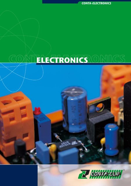
ELECTRONICS
ELECTRONICS
ELECTRONICS
- No tags were found...

Create successful ePaper yourself
Turn your PDF publications into a flip-book with our unique Google optimized e-Paper software.
<strong>ELECTRONICS</strong><br />
CONTA-<strong>ELECTRONICS</strong>
CONTA-<strong>ELECTRONICS</strong><br />
CONTA-<strong>ELECTRONICS</strong><br />
Program Overview<br />
CONTA-CLIP - The Company 3<br />
CONTA-CLIP - on the Internet 4<br />
CONTA-<strong>ELECTRONICS</strong><br />
General Information 5<br />
Product Overview 6<br />
DC Power Supplies 10<br />
Primary clocked DC power supplies 14<br />
AC/DC regulated power supply modules 16<br />
AC/DC unregulated power supply modules 22<br />
AC/AC transformer power supply modules 23<br />
AC/DC rectifier modules 25<br />
DC/DC stabilized converter modules 27<br />
UC/DC stabilized converter modules 30<br />
Overvoltage Protection CONTA-PROTECT 32<br />
Overvoltage arresters, type 1|2|3| (B|C|D) 34<br />
Overvoltage arresters, type 2 (C) 35<br />
Overvoltage arresters, type 3 (D) 38<br />
Interference-elimination link modules 39<br />
Functional Relays 40<br />
Multi-functional timing relay components 44<br />
Clock-pulse generator dual-timing relay modules 46<br />
Staircase lighting time-limit switch components 48<br />
Undervoltage-monitoring relay components 50<br />
Star-delta switching relay components 52<br />
Auto-Off-On relay components 54<br />
Analog output modules with<br />
HAND/OFF/AUTOMATIC operation 56<br />
Digital switch modules with HAND/OFF/<br />
AUTOMATIC operation 58<br />
Indication modules LED 66<br />
Fault warning modules 67<br />
Relay Systems 68<br />
Compact plug relays 70<br />
Plug relay system 76<br />
Relay modules with 1 changeover 90<br />
Relay modules with 2 changeovers 91<br />
Compact relay modules 92<br />
Relay modules with 1 changeover, 16 A 94<br />
Multi-channel relay modules with 1 changeover<br />
and fuse 95<br />
Multi-channel relay modules with 1 changeover 96<br />
Multi-channel relay modules with 1 changeover<br />
and switch 98<br />
Multi-channel relay modules<br />
with 1 changeover, 16 A 100<br />
Multi-channel relay modules with<br />
2 changeovers 102<br />
Opto-coupler | Solid-state 104<br />
Solid-state compact 106<br />
Multi-channel opto-coupler modules 110<br />
Multi-channel solid-state output modules 112<br />
Solid-state relays 113<br />
Fuse, Component, Diode<br />
and Indicator Modules 114<br />
Fuse modules 116<br />
Component modules 117<br />
Diode modules 118<br />
Lamp test modules 120<br />
Interface Modules 122<br />
Interface modules for RJ45 and USB 124<br />
Interface modules for D-Sub 125<br />
Interface modules for ribbon cable 128<br />
Interface modules for EDAC connectors 130<br />
EDAC accessories 132<br />
Converter Units 134<br />
Signal converters<br />
for thermal sensors 136<br />
Signal converters<br />
for voltage and current 137<br />
Signal converters<br />
for potentiometer signals 138<br />
Multi-functional signal-converter units<br />
for voltage and current 139<br />
Multi-functional signal-converter units<br />
with relays 141<br />
Multi-functional signal-converter units<br />
for frequency signals 142<br />
Analog signal-converter modules<br />
without galvanic isolation 144<br />
Analog signal-converter modules<br />
with galvanic isolation 146<br />
Signal-converter units<br />
for potentiometer signals 147<br />
Signal-converter units<br />
for thermal sensors 148<br />
Analog signal-converter unit<br />
without external power supply 149<br />
Accessories 150<br />
Locking-base system 152<br />
Mounting rails 154<br />
End brackets 156<br />
Terminal markers and identification systems 157<br />
Shield-connection clips 158<br />
Fuse cartridges 160<br />
Device and installation markers in<br />
Maxicard format 162<br />
Equipment and installation markers<br />
GKE adhesive device labels 163<br />
List of order numbers 165<br />
List of types and order numbers<br />
alphabetical/numerical<br />
All rights reserved.
CONTA-CLIP<br />
The Company<br />
We are your global partner for electrical and<br />
electronic connection technology, customised<br />
system solutions and marking components.<br />
CONTA-CLIP is the perfect solution for anyone<br />
in the electrical technology business, and for<br />
good reason.<br />
CONTA-CLIP has been developing products for<br />
control and automation engineering for<br />
decades.<br />
With its resolute product development and pricing<br />
strategies, CONTA-CLIP is able to offer a<br />
comprehensive line of connection systems, electronic<br />
functional modules and marking solutions.<br />
For years, CONTA-CLIP has been an<br />
established name in systems and mechanical<br />
engineering. This has been achieved through<br />
exceptional levels of versatility and the highest<br />
standards of quality.<br />
CONTA-CLIP products are tested and certified<br />
by all well-known certifying institutes around the<br />
world. In order to ensure that our products<br />
remain at the cutting edge of technological<br />
development, we have been successfully cooperating<br />
for years with experts at TÜV Rheinland<br />
Product Safety GmbH. They test our products to<br />
ensure conformity with international (IEC) and<br />
European standards (EN). These tests are documented<br />
in inspection reports. At the beginning<br />
of 1994, our company was certified for the first<br />
time to DIN ISO 9001 by the DQS, an independent,<br />
German based institute for quality management<br />
system certification. In 2004, we successfully<br />
gained certification in accordance with DIN<br />
ISO 9001/2000.<br />
We have provided objective proof that we are in<br />
full control of the technical, administrative and<br />
human factors that influence the quality of our<br />
products and services. Within the framework of<br />
our continually growing marketing network, our<br />
top quality products and services are being<br />
offered in all of the key world markets.<br />
Our company philosophy is characterised by<br />
clear-cut principles! Our qualified and motivated<br />
staff is our company’s most important asset in<br />
our quest for success. The company management<br />
supports and demands initiative and commitment.<br />
This results in a high level of individual<br />
responsibility. That in turn enables us to recognise<br />
customer-requirements and market trends<br />
at an early stage and respond with high-quality<br />
CONTA-CLIP product solutions.<br />
Over many years, a corporate culture has developed<br />
whose most important virtues are reliability,<br />
fairness and loyalty – a corporate culture that<br />
is mirrored in our motto – “Technology that connects”.<br />
3
CONTA-<strong>ELECTRONICS</strong><br />
CONTA-CLIP<br />
on the Internet<br />
You can find all about product innovations, trade fair appointments,<br />
press releases, and more at our official CONTA-CLIP<br />
web site.<br />
If you want to make sure you do not miss any news, then subscribe<br />
with no obligation to our CONTA-CLIP newsletter by<br />
e-mail.<br />
www.conta-clip.com<br />
in Germany:<br />
www.conta-clip.de<br />
in France:<br />
www.conta-clip.fr<br />
in Holland:<br />
www.conta-clip.nl<br />
in Italy:<br />
www.conta-clip.it<br />
USA<br />
www.contaclipinc.com<br />
4
CONTA-CLIP<br />
Overview<br />
CONTA-CLIP: for many years, this name has stood for innovative products in the field of mechanical and<br />
systems engineering. With its wide variety of electrical connection system products, CONTA-CLIP has<br />
been the industry partner for decades. You can find solutions to your applications quickly by using the<br />
clear organization in our catalogs, which divide the products into three areas.<br />
CONTA-CONNECT<br />
• Connection level for the switchgear cabinet<br />
and control engineering<br />
• Tools for working with conductors and cables<br />
• Branch and terminal housing in a variety of<br />
designs and materials<br />
• CONTA-LABEL marking systems for labeling<br />
terminal blocks, devices, conductors and<br />
cables<br />
CONTA-CON<br />
• Connection level for the PCB<br />
• PCB terminals and PCB connectors<br />
CONTA-<strong>ELECTRONICS</strong><br />
•Passive and active coupling level for analog<br />
and digital signals<br />
Our workers and production facilities are your<br />
guarantee for permanent and continuous quality.<br />
This quality has been repeatedly proven to be<br />
a level above the national and international certifications<br />
of well-known testing institutions.<br />
The plastic materials that we use are specialized<br />
for the demands of electro-technical systems,<br />
and are free from toxic contaminants.<br />
You are assured of a trouble-free electrical connection<br />
because of our combination of materials<br />
which are specially fit to each other, and the<br />
high quality surfaces of the metal parts.<br />
5
CONTA-<strong>ELECTRONICS</strong><br />
CONTA-<strong>ELECTRONICS</strong><br />
Product Overview<br />
One-phase DC power<br />
supplies PGSV<br />
Three-phase DC power<br />
supplies PGSV<br />
AC/DC regulated power<br />
supply modules VMG<br />
AC/DC regulated power<br />
supply modules VMG/ADJ<br />
Page 14 Page 15 Page 16-18 Page 19<br />
AC/DC regulated power<br />
supply modules VMGS<br />
AC/DC unregulated power<br />
supply modules VMO<br />
AC/AC transformer power<br />
supply modules VMAC<br />
AC/DC rectifier modules<br />
GM<br />
Page 20-21 Page 22 Page 23-24 Page 25-26<br />
DC/DC stabilized converter<br />
modules VSTAB<br />
DC/DC stabilized converter<br />
modules DC-DC<br />
UC/DC converter modules<br />
ACDCG<br />
CONTA-PROTECT Overvoltage<br />
arresters, type 1|2|3 (B|C|D)<br />
Page 27 Page 28-29 Page 30 Page 34<br />
CONTA-PROTECT<br />
Overvoltage arresters type 2 (C)<br />
CONTA-PROTECT<br />
Overvoltage arresters type 3 (D)<br />
Interference-elimination<br />
link modules IF-OF<br />
Multi-functional timing<br />
relays MFR 1<br />
Page 35-37 Page 38 Page 39 Page 45<br />
Multi-functional timing<br />
relays MFR 4<br />
Multi-functional timing<br />
relays MFR 5<br />
Clock-pulse generator dualtiming<br />
relays MFR 6<br />
Staircase lighting time-limit<br />
switch TSR 1<br />
Page 45 Page 45 Page 47 Page 49<br />
Staircase lighting timelimit<br />
switch TSR 2<br />
Undervoltage monitoring<br />
relays USR 1<br />
Undervoltage monitoring<br />
relays USR 2<br />
Star-delta switching relays<br />
SDSR 1<br />
Page 49 Page 51 Page 51 Page 53<br />
6
CONTA-<strong>ELECTRONICS</strong><br />
Product Overview<br />
Star-delta switching relays<br />
SDSR 2<br />
Auto-Off-On relays<br />
RM/HA/24 VUC<br />
Analog output modules<br />
AO-1-2 S<br />
Analog output modules<br />
AO-4-2 S<br />
Page 53 Page 54 Page 56 Page 57<br />
Digital switch modules with HAND/<br />
Digital switch modules with HAND/<br />
Digital switch modules with HAND/<br />
Digital switch modules with HAND/<br />
OFF/AUTOMATIC operation MGW<br />
OFF/AUTOMATIC operation RIM<br />
OFF/AUTOMATIC operation OD<br />
OFF/AUTOMATIC operation ASB<br />
Page 58 Page 59 Page 60 Page 61<br />
Digital switch modules with HAND/<br />
Digital switch modules with HAND/<br />
Digital switch modules with HAND/OFF/<br />
Digital switch modules with HAND/OFF/<br />
OFF/AUTOMATIC operation HLS<br />
OFF/AUTOMATIC operation HLSW<br />
AUTOMATIC operation and watchdog IM<br />
AUTOMATIC operation and watchdog ASBW<br />
Page 62 Page 62 Page 63 Page 63<br />
Digital switch modules with HAND/<br />
OFF/AUTOMATIC operation AU<br />
Indication modules LED 8 Fault warning modules ST Compact plug relays ZPRC<br />
Tension-spring relay terminals<br />
Page 64-65 Page 66 Page 67 Page 72-73<br />
Compact plug relays PRC<br />
Plug relay system PRS 1<br />
Plug relay system PRS 2<br />
Plug relay system PRS 2 G<br />
Screw-connection relay terminals<br />
Screw-connection 1 CO relays<br />
Screw-connection 2 CO relays<br />
Screw-connection 2 CO relays<br />
Page 74-75 Page 78-79 Page 80-81 Page 82-83<br />
Plug relay system PRS 4<br />
Screw-connection 4 CO relays<br />
Plug relay system PRS 4 G<br />
Screw-connection 4 CO relays<br />
Plug relay system PRS 4 G eco<br />
Screw-connection 4 CO relays<br />
Relay modules<br />
1 CO RM 1<br />
Page 84-85 Page 86-87 Page 88-89 Page 90<br />
7
CONTA-<strong>ELECTRONICS</strong><br />
CONTA-<strong>ELECTRONICS</strong><br />
Product Overview<br />
Relay modules<br />
2 CO RM 1/2<br />
Relay modules<br />
RM-S<br />
Relay modules<br />
1 CO RML<br />
Relay modules<br />
1 CO RIM F<br />
Page 91 Page 92-93 Page 94 Page 95<br />
Relay modules<br />
1 CO RIM<br />
Relay modules<br />
1 CO RIM S<br />
Relay modules<br />
1 CO RIM-16 A<br />
Relay modules<br />
2 CO RIM<br />
Page 95-96 Page 98-99 Page 100-101 Page 102-103<br />
Solid-state compact PSC<br />
Solid-state terminals, tension-spring connection<br />
Solid-state compact PSC<br />
Solid-state terminals, screw-clamp<br />
Opto-coupler modules<br />
OKI AC/DC<br />
Opto-coupler modules<br />
OKI DC<br />
Page 108 Page 109 Page 110 Page 111<br />
Solid-state output modules<br />
SSOIF<br />
Solid-state relays<br />
OPTO 22<br />
Fuse modules<br />
SM<br />
Component modules<br />
BSM<br />
Page 112 Page 112 Page 116 Page 117<br />
Diode modules DM Lamp test modules LPM Lamp test modules LTRS Interface modules<br />
RJ 45 USB<br />
Page 118-119 Page 120 Page 121 Page 124<br />
Interface modules<br />
SD... C<br />
Interface modules<br />
SD<br />
Interface modules<br />
FBK... C<br />
Interface modules<br />
FBK 2/FBK LA<br />
Page 125 Page 126-127 Page 128 Page 129<br />
8
CONTA-<strong>ELECTRONICS</strong><br />
Product Overview<br />
Interface modules<br />
OE-E<br />
EDAC accessories<br />
Temperature converter<br />
units CML-PT100-UI<br />
Voltage and current<br />
converter units CML-UI-UI<br />
Page 130-131 Page 132 Page 136 Page 137<br />
Potentiometric converter<br />
units CML-POT-UI<br />
Multi-functional signal<br />
converter units CMS-UI-UI<br />
Multi-functional signal converter<br />
units CMS-UI 60-UI<br />
Multi-functional signal<br />
converter units CMS-UI-R<br />
Page 138 Page 139 Page 140 Page 141<br />
Multi-functional signal<br />
converter units CMS-F-UI<br />
Analog signal converter modules<br />
without galvanic isolation CAE<br />
Potentiometric modules<br />
CAE/POT<br />
Temperature converter<br />
units PT 100<br />
Page 142 Page 144-146 Page 147 Page 148<br />
Analog signal converter<br />
unit EG 3 SWW<br />
Locking-base system<br />
RS-SP<br />
Mounting rails<br />
TS<br />
End brackets<br />
ES/ZES<br />
Page 149 Page 152-153 Page 154-155 Page 156<br />
Terminal markers and<br />
identification system PMC<br />
Shield-connection clip<br />
SAB<br />
Fuse elements<br />
SI<br />
Device and installation markers<br />
Maxicard GS<br />
Page 157 Page 158-159 Page 160-161 Page 162<br />
Device and installation markers<br />
Adhesive device labels GKE<br />
Device and installation markers<br />
GKE adhesive device labels on DIN A4 sheets<br />
Page 163 Page 164<br />
9
CONTA-<strong>ELECTRONICS</strong><br />
DC Power Supplies<br />
The 24 V DC control voltage has come to globally dominate in<br />
systems and machines in automation engineering, in the DC<br />
power supplies for encoders, input signals, actuators and electronic<br />
components. However the voltage range from 6 V DC<br />
to 60 V DC is also required for analog and digital signals in<br />
various control schemes.<br />
The functionality of an electronic control is largely dependent<br />
on the reliability of its corresponding power supply. A stable<br />
and safe power and voltage supply guarantees a trouble-free<br />
production process in systems and mechanical engineering.<br />
CONTA-CLIP offers many different components: smoothed or<br />
un-smoothed transformers, unstabilized or stabilized mains<br />
power supplies, and also primary clocked power supplies.<br />
6
Primary Clocked DC Power Supplies PGSV<br />
DC Power Supplies<br />
CONTA-CLIP distinguishes between one-phase and threephase<br />
devices with the PGSV primary clocked DC power supplies.These<br />
are primary accessed via a wide-range input. This<br />
wide-range input enables the PGSV power supplies to be<br />
globally compatible in a wide variety of applications.<br />
In addition, this product line is characterised by high efficiency,<br />
light weight, small size. They are no-load safe, can be<br />
switched in parallel, and have outputs which are short-circuit<br />
protected.<br />
Overview<br />
a<br />
Global use with<br />
wide-range input.<br />
d<br />
b<br />
c<br />
a<br />
b<br />
c<br />
A sturdy metal enclosure with IP 20<br />
protection and<br />
higher efficiency.<br />
High-quality connection terminals<br />
from CONTA-CLIP.<br />
e<br />
d<br />
Easy mounting to a<br />
TS 35 rail.<br />
e<br />
Adjustable output voltage/<br />
no-load and short-circuit safe.<br />
Features<br />
· High efficiency, light weight, and small size - achieved with<br />
primary switched-mode regulator technology.<br />
· All-round use in grid - fulfils the high EMC demands of the<br />
residential and industrial sectors.<br />
· Extra-low safety voltage output with non-grounded circuit<br />
for safer isolation.<br />
· Outlet is switchable in parallel or series.<br />
· Outlet is no-load safe and has permanent short-circuit<br />
protected.<br />
· Overvoltage protection.<br />
11
CONTA-<strong>ELECTRONICS</strong><br />
DC Power Supplies<br />
VMG AC/DC stabilized power supply modules<br />
VMG power supply modules convert the mains voltage from<br />
230 V into a linear-stabilized DC voltage. They are available in<br />
varying output voltages – 5 V, 12 V, 15 V, and 24 V – with various<br />
high-performance transformers. A module is also available<br />
which features adjustable outlet voltage from 1.5 V to<br />
26 V.<br />
VMGS AC/DC stabilized power supply modules<br />
VMGS power supply modules convert the mains voltage from<br />
230 V into two linear stabilized DC voltages. They are available<br />
in various output voltages – 2 x 5 V, 2 x 12 V, 2 x 15 V,<br />
and 2 x 24 V – with varying high-performance transformers.<br />
VMO AC/DC unstabilized power supply modules<br />
VMO power supply modules converts the mains voltage from<br />
230 V into a buffered DC voltage. They are available in 12 V<br />
and 24 V output voltage versions, with various high-performance<br />
transformers.<br />
VMAC AC/AC transformer power supply modules<br />
VMAC AC/AC power supply modules offer the simplest possibility<br />
to implement a AC control-voltage level for the<br />
switchgear cabinet. All modules are secured with a safety<br />
fuse on the primary and secondary sides. They are available<br />
in 12 V and 24 V versions, with various high-performance<br />
transformers.<br />
12
DC Power Supplies<br />
DC Power Supplies<br />
GM AC/DC rectifier modules<br />
Rectifier modules make possible the simple conversion of<br />
existing alternating voltage into a buffered or unbuffered<br />
direct voltage.<br />
VSTAB stabilized DC/DC converter modules<br />
VSTAB power supply modules enable the conversion of a<br />
large alternating voltage into a smaller one. An extra power<br />
supply is no longer necessary. All modules feature a stabilized<br />
alternating voltage for output. They are available in various<br />
output voltages – 5 V, 10 V, 12 V, 15 V and 24 V – for every<br />
application.<br />
DC-DC stabilized DC/DC converter modules<br />
DC/DC converter modules make possible the conversion of an<br />
existing large DC voltage into a smaller DC voltage. An extra<br />
power supply is no longer necessary. All modules offer an output<br />
which is short-circuit proof. They are available in various<br />
output voltages – 5 V, 12 V, 15 V and 24 V – and also in various<br />
current strengths for every application.<br />
ACDCG UC/DC converter modules<br />
The ACDCG power supply modules convert an input-side alternating<br />
or DC voltage into an output-side linear-stabilized DC<br />
voltage. All modules offer an output which is short-circuit<br />
proof. They are available in various output voltages – 5 V, 12 V,<br />
15 V and 24 V – for every application.<br />
13
CONTA-<strong>ELECTRONICS</strong><br />
One-phase DC power supplies PGSV<br />
One-phase primary clocked DC power supplies<br />
PSP 230 V/24 V-1.3 A PSP 230 V/24 V-2.5 A PSP 230 V/24 V-5 A PSP 230 V/24 V-10 A<br />
· Mount on TS 35<br />
· Primary clocked DC power supply according to<br />
IEC 60950, DIN EN 60950, VDE 0805, UL 60950<br />
· Wide-range input<br />
· Optimized for 30 to 240 watts<br />
· No-load and short-circuit safe<br />
· Thermal overload protection<br />
· U-I characteristic curve<br />
· Sturdy metal enclosure<br />
· Self-cooling via natural convection in horizontal<br />
mounting position<br />
Characteristic curve<br />
Characteristic curve<br />
Characteristic curve<br />
Characteristic curve<br />
UE = 230V AC<br />
UE = 230V AC<br />
UE = 230V AC<br />
UE = 230V AC<br />
Type<br />
Cat. no./Qty. p.pck.<br />
Connection type<br />
Size (L x W x H) with TS 35 x 7.5<br />
Weight<br />
Mechanical design<br />
Fastening to rail<br />
Cooling<br />
Shockproof<br />
Enclosure<br />
Protection<br />
Protect. class<br />
Electrical design<br />
Prim. clocked switched power adapter<br />
Electrical safety<br />
Disturbance emission<br />
Interference immunity<br />
Test voltage<br />
Ambient temperature<br />
Storage temperature<br />
Efficiency<br />
Thermal overload protection<br />
No-load and short-circuit safe<br />
Input circuit<br />
Input voltage<br />
Input voltage range<br />
Frequency<br />
Input current (230V AC)<br />
Inrush current<br />
Mains failure bridging<br />
Overvoltage protection<br />
Connection cross-section<br />
Connections<br />
Output circuit<br />
Output voltage<br />
Output voltage range<br />
Output current<br />
Ripple<br />
Current limitation<br />
Connection cross-section<br />
Connections<br />
PSP 230 V/24 V-1.3 A<br />
15193.2/1<br />
connector<br />
78 x 40 x 95mm<br />
300 g<br />
TS 35 (EN 50022)<br />
self-cooling<br />
VBG 4<br />
encapsulated for use in<br />
switch cabinet<br />
IP 20<br />
I<br />
acc. to VDE 0805,<br />
DIN EN 60950,<br />
IEC 60950, UL 60950<br />
EN 50081-1 (residential)<br />
EN 50082-2 (industrial)<br />
4 kV<br />
0 to +50°C<br />
-25 to +85°C<br />
78 %<br />
yes<br />
yes<br />
230 V AC<br />
90-264 V AC<br />
50-60 Hz<br />
0.3A typ.<br />
< 10 As typ.<br />
> 20 ms at<br />
rated voltage<br />
varistor in primary<br />
circuit<br />
2.5 mm 2<br />
connector<br />
24 V DC, SELV<br />
-<br />
1.3 A DC<br />
< 100 m Vss<br />
see characteristic curve<br />
2.5 mm 2<br />
connector<br />
PSP 230 V/24 V-2.5 A<br />
15194.2/1<br />
connector<br />
130 x 56 x 112mm<br />
700 g<br />
TS 35 (EN 50022)<br />
self-cooling<br />
VBG 4<br />
encapsulated for use in<br />
switch cabinet<br />
IP 20<br />
I<br />
acc. to VDE 0805,<br />
DIN EN 60950,<br />
IEC 60950, UL 60950<br />
EN 50081-1 (residential)<br />
EN 50082-2 (industrial)<br />
4 kV<br />
0 to +60°C<br />
-25 to +85°C<br />
81 %<br />
yes<br />
yes<br />
230 V AC<br />
90-264 V AC<br />
50-60 Hz<br />
0.6 A typ.<br />
< 10 As typ.<br />
> 20 ms at<br />
rated voltage<br />
varistor in<br />
primary circuit<br />
2.5 mm 2<br />
connector<br />
24 V DC, SELV<br />
22-28.8 V DC,<br />
adjustable<br />
2,5 A DC<br />
< 100 m Vss<br />
see characteristic curve<br />
2.5 mm 2<br />
connector<br />
PSP 230 V/24 V-5 A<br />
15195.2/1<br />
connector<br />
130 x 71 x 112mm<br />
900 g<br />
TS 35 (EN 50022)<br />
self-cooling<br />
VBG 4<br />
encapsulated for use in<br />
switch cabinet<br />
IP 20<br />
I<br />
acc. to VDE 0805,<br />
DIN EN 60950,<br />
IEC 60950, UL 60950<br />
EN 50081-1 (residential)<br />
EN 50082-2 (industrial)<br />
4 kV<br />
0 to +50°C<br />
-25 to +85°C<br />
82 %<br />
yes<br />
yes<br />
230 V AC<br />
90-264 V AC<br />
50-60 Hz<br />
1.2 A typ.<br />
< 10 As typ.<br />
> 20 ms at<br />
rated voltage<br />
varistor in<br />
primary circuit<br />
2.5 mm 2<br />
connector<br />
24 V DC, SELV<br />
22-28.8 V DC,<br />
adjustable<br />
5.0 A DC<br />
< 100 m Vss<br />
see characteristic curve<br />
2.5 mm 2<br />
connector<br />
PSP 230 V/24 V-10 A<br />
15337.2/1<br />
connector<br />
95 x 115 x 120mm<br />
1,100 g<br />
TS 35 (EN 50022)<br />
self-cooling<br />
VBG 4<br />
encapsulated for use in<br />
switch cabinet<br />
IP 20<br />
I<br />
acc. to VDE 0805,<br />
DIN EN 60950,<br />
IEC 60950, UL 60950<br />
EN 50081-1 (residential)<br />
EN 50082-2 (industrial)<br />
4 kV<br />
0 to +50°C<br />
-25 to +85°C<br />
83 %<br />
yes<br />
yes<br />
230 V AC<br />
97-130/195-264 V AC<br />
50-60 Hz<br />
2.5 A typ.<br />
< 30 As typ.<br />
> 20 ms at<br />
rated voltage<br />
varistor in<br />
primary circuit<br />
2.5 mm 2<br />
connector<br />
24 V DC, SELV<br />
22 - 28.8 V DC,<br />
adjustable<br />
10.0 A DC<br />
< 100 m Vss<br />
see characteristic curve<br />
2.5 mm 2<br />
connector<br />
14
Three-phase DC power supplies PGSV<br />
Three-phase primary clocked DC power supplies<br />
DC Power Supplies<br />
PSP 500 V/24 V-10 A PSP 500 V/24 V-20 A PSP 500 V/24 V-40 A<br />
· Mount on TS 35<br />
· Primary clocked DC power supply acc. to IEC<br />
60950, DIN EN 60950, VDE 0805, UL 60950<br />
· Wide-range input<br />
· Optimized for 120 to 960 watts<br />
· No-load and short-circuit safe<br />
· Thermal overload protection<br />
· U-I characteristic curve<br />
· Sturdy metal enclosure<br />
· Self-cooling via natural convection in horizontal<br />
mounting position<br />
Characteristic curve<br />
Characteristic curve<br />
Characteristic curve<br />
UE = 500 V AC<br />
UE = 500 V AC<br />
UE = 500 V AC<br />
Type<br />
Cat. no./Qty. p.pck.<br />
Connection type<br />
Size (L x W x H) with TS 35 x 7.5<br />
Weight<br />
Mechanical design<br />
Fastening to rail<br />
Cooling<br />
Shockproof<br />
Enclosure<br />
Protection<br />
Protect. class<br />
Electrical design<br />
Prim. clocked switched power adapter<br />
Electrical safety<br />
Disturbance emission<br />
Interference immunity<br />
Test voltage<br />
Ambient temperature<br />
Storage temperature<br />
Efficiency<br />
Thermal overload protection<br />
No-load and short-circuit safe<br />
Input circuits<br />
Input voltage<br />
Input voltage range<br />
Frequency<br />
Input current (400 V AC)<br />
Inrush current<br />
Mains failure bridging<br />
Overvoltage protection<br />
Connection cross-section<br />
Connections<br />
Output circuit<br />
Output voltage<br />
Output voltage range<br />
Output current<br />
Ripple<br />
Current limitation<br />
Connection cross-section<br />
Connections<br />
PSP 500 V/24 V-10 A<br />
15338.2/1<br />
connector<br />
95 x 115 x 120mm<br />
950 g<br />
TS 35 (EN 50022)<br />
self-cooling<br />
VBG 4<br />
encapsulated for use in<br />
switch cabinet<br />
IP 20<br />
I<br />
acc. to VDE 0805,<br />
DIN EN 60950,<br />
IEC 60950, UL 60950<br />
EN 50081-1 (residential)<br />
EN 50082-2 (industrial)<br />
4 kV<br />
0 to +50°C<br />
-25 to +85°C<br />
82 %<br />
yes<br />
yes<br />
3 x 500 V AC<br />
325-550 V AC<br />
50-60 Hz<br />
3 x 0.6 A typ.<br />
< 20 As typ.<br />
> 10 ms at<br />
rated voltage<br />
varistor in<br />
primary circuit<br />
2.5 mm 2<br />
connector<br />
24 V DC<br />
22.8 to 28.8 V DC,<br />
adjustable<br />
10,0 A DC<br />
< 100 m Vss<br />
see characteristic curve<br />
2.5 mm 2<br />
connector<br />
PSP 500 V/24 V-20 A<br />
15369.2/1<br />
connector<br />
95 x 220 x 120mm<br />
2.000 g<br />
TS 35 (EN 50022)<br />
self-cooling<br />
VBG 4<br />
encapsulated for use in<br />
switch cabinet<br />
IP 20<br />
I<br />
acc. to VDE 0805,<br />
DIN EN 60950,<br />
IEC 60950, UL 60950<br />
EN 50081-1 (residential)<br />
EN 50082-2 (industrial)<br />
4 kV<br />
0 to +50°C<br />
-25 to +85°C<br />
87 %<br />
yes<br />
yes<br />
3 x 500 V AC<br />
325-550 V AC<br />
50-60 Hz<br />
3 x 1.2 A typ.<br />
< 30 As typ.<br />
> 10 ms at<br />
rated voltage<br />
varistor in<br />
primary circuit<br />
2.5 mm 2<br />
connector<br />
24 V DC<br />
22.8 - 28.8 V DC,<br />
adjustable<br />
20,0 A DC<br />
< 100 m Vss<br />
see characteristic curve<br />
2.5 mm 2<br />
connector<br />
PSP 500 V/24 V-40 A<br />
15370.2/1<br />
connector<br />
115 x 260 x 120mm<br />
3.800 g<br />
TS 35 (EN 50022)<br />
self-cooling<br />
VBG 4<br />
encapsulated for use in<br />
switch cabinet<br />
IP 20<br />
I<br />
acc. to VDE 0805,<br />
DIN EN 60950,<br />
IEC 60950, UL 60950<br />
EN 50081-1 (residential)<br />
EN 50082-2 (industrial)<br />
4 kV<br />
0 to +50°C<br />
-25 to +85°C<br />
88 %<br />
yes<br />
yes<br />
3 x 500 V AC<br />
325-550 V AC<br />
50-60 Hz<br />
3 x 2.4 A typ.<br />
< 30 As typ.<br />
> 10 ms at<br />
rated voltage<br />
varistor in<br />
primary circuit<br />
2.5 mm 2<br />
connector<br />
24 V DC<br />
22.8 - 28.8 V DC,<br />
adjustable<br />
40.0 A DC<br />
< 100m Vss<br />
see characteristic curve<br />
6 mm 2<br />
connector<br />
15
CONTA-<strong>ELECTRONICS</strong><br />
AC/DC regulated power supply modules VMG<br />
VMG/5-0.8 VMG/5-2 VMG/12-0.5 VMG/12-1<br />
· Mount on TS 32/TS 35<br />
· AC/DC power supply<br />
· Linear regulated on output side<br />
DC voltage VMG 1x... V DC<br />
· Input voltage: 230 V AC<br />
· Thermal overload protection<br />
· Short-circuit safe output<br />
· Other input and output voltages available<br />
on request<br />
1 2 3<br />
Circuit diagram Circuit diagram Circuit diagram<br />
Type<br />
Cat. no./Qty. p.pck.<br />
Image<br />
Connection type<br />
Size (L x W x H) with TS 35 x 7.5<br />
Weight<br />
General information<br />
DIN-VDE specifications<br />
Test voltage transformer<br />
Operating temperature<br />
Important notes<br />
Insulation stripping length<br />
Conductor cross-section<br />
Input data<br />
Input voltage<br />
Rated consumption<br />
Frequency<br />
Primary fuse<br />
Output data<br />
Output voltage, ± 5%<br />
Max. output current<br />
Max. residual ripple<br />
Short-circuit safe<br />
VMG/5-0.8<br />
5880.3/1<br />
1<br />
screw-clamp<br />
87 x 83 x 73mm<br />
420 g<br />
DIN EN 50178,<br />
DIN VDE 0110,<br />
pollution degree 2,<br />
overvoltage cat. III,<br />
DIN VDE 0551<br />
4 kV<br />
-20 to +50°C<br />
7mm<br />
0.2-2.5mm 2 /AWG 22-14<br />
230 V AC<br />
+10%<br />
10 VA<br />
50/60 Hz<br />
63 mA slow-acting<br />
5 V ±5%<br />
0.55 A<br />
< 40 mV pp<br />
yes<br />
VMG/5-2<br />
5882.3/1<br />
3<br />
screw-clamp<br />
87 x 167 x 110mm<br />
1.105 g<br />
DIN EN 50178,<br />
DIN VDE 0110,<br />
pollution degree 2,<br />
overvoltage cat. III,<br />
DIN VDE 0551<br />
4 kV<br />
-20 to +50°C<br />
7mm<br />
0.2-2.5mm 2 /AWG 22-14<br />
230 V AC<br />
+10%<br />
35 VA<br />
50/60 Hz<br />
0.25 A slow-acting<br />
5 V ±5%<br />
2 A<br />
< 60 mV pp<br />
yes<br />
VMG/12-0.5<br />
5884.3/1<br />
1<br />
screw-clamp<br />
87 x 83 x 73mm<br />
480 g<br />
DIN EN 50178,<br />
DIN VDE 0110,<br />
pollution degree 2,<br />
overvoltage cat. III,<br />
DIN VDE 0551<br />
4 kV<br />
-20 to +50°C<br />
7mm<br />
0.2-2.5mm 2 /AWG 22-14<br />
230 V AC<br />
+10%<br />
10 VA<br />
50/60 Hz<br />
63 mA slow-acting<br />
12 V ±5%<br />
0.3 A<br />
< 40 mV pp<br />
yes<br />
VMG/12-1<br />
5885.3/1<br />
2<br />
screw-clamp<br />
87 x 109 x 86mm<br />
965 g<br />
DIN EN 50178,<br />
DIN VDE 0110,<br />
pollution degree 2,<br />
overvoltage cat. III,<br />
DIN VDE 0551<br />
4 kV<br />
-20 to +50°C<br />
7mm<br />
0.2-2.5mm 2 /AWG 22-14<br />
230 V AC<br />
+10%<br />
28 VA<br />
50/60 Hz<br />
0.2 A slow-acting<br />
12 V ±5%<br />
1 A<br />
< 40 mV pp<br />
yes<br />
16
AC/DC regulated power supply modules VMG<br />
DC Power Supplies<br />
VMG/12-2 VMG/15-0.4 VMG/15-1 VMG/24-0.3<br />
· Mount on TS 32/TS 35<br />
· AC/DC power supply<br />
· Linear regulated on output side<br />
DC voltage VMG 1x... V DC<br />
· Input voltage: 230 V AC<br />
· Thermal overload protection<br />
· Short-circuit safe output<br />
· Other input and output voltages available<br />
on request<br />
1 2 3<br />
Circuit diagram Circuit diagram Circuit diagram<br />
Type<br />
Cat. no./Qty. p.pck.<br />
Image<br />
Connection type<br />
Size (L x W x H) with TS 35 x 7.5<br />
Weight<br />
General information<br />
DIN-VDE specifications<br />
Test voltage transformer<br />
Operating temperature<br />
Important notes<br />
Insulation stripping length<br />
Conductor cross-section<br />
Input data<br />
Input voltage<br />
Rated consumption<br />
Frequency<br />
Primary fuse<br />
Output data<br />
Output voltage, ± 5%<br />
Max. output current<br />
Max. residual ripple<br />
Short-circuit safe<br />
VMG/12-2<br />
5886.3/1<br />
3<br />
screw-clamp<br />
87 x 167 x 110mm<br />
975 g<br />
DIN EN 50178,<br />
DIN VDE 0110,<br />
pollution degree 2,<br />
overvoltage category III,<br />
DIN VDE 0551<br />
4 kV<br />
-20 to +50°C<br />
7mm<br />
0.2-2.5mm 2 /AWG 22-14<br />
230 V AC<br />
+10%<br />
58 VA<br />
50/60 Hz<br />
0.5 A slow-acting<br />
12 V ±5%<br />
2 A<br />
< 60 mV pp<br />
yes<br />
VMG/15-0.4<br />
6541.2/1<br />
1<br />
screw-clamp<br />
87 x 83 x 73mm<br />
800 g<br />
DIN EN 50178,<br />
DIN VDE 0110,<br />
pollution degree 2,<br />
overvoltage category III,<br />
DIN VDE 0551<br />
4 kV<br />
-20 to +50°C<br />
7mm<br />
0.2-2.5mm 2 /AWG 22-14<br />
230 V AC<br />
+10%<br />
10 VA<br />
50/60 Hz<br />
63 mA slow-acting<br />
15 V ±5%<br />
0.27 A<br />
< 60 mV pp<br />
yes<br />
VMG/15-1<br />
6542.2/1<br />
2<br />
screw-clamp<br />
87 x 109 x 86mm<br />
750 g<br />
DIN EN 50178,<br />
DIN VDE 0110,<br />
pollution degree 2,<br />
overvoltage category III,<br />
DIN VDE 0551<br />
4 kV<br />
-20 to +50°C<br />
7mm<br />
0.2-2.5mm 2 /AWG 22-14<br />
230 V AC<br />
+10%<br />
28 VA<br />
50/60 Hz<br />
0,2A slow-acting<br />
15 V ±5%<br />
1 A<br />
< 40 mV pp<br />
yes<br />
VMG/24-0.3<br />
5888.3/1<br />
1<br />
screw-clamp<br />
87 x 83 x 73mm<br />
420 g<br />
DIN EN 50178,<br />
DIN VDE 0110,<br />
pollution degree 2,<br />
overvoltage category III,<br />
DIN VDE 0551<br />
4 kV<br />
-20 to +50°C<br />
7mm<br />
0.2-2.5mm 2 /AWG 22-14<br />
230 V AC<br />
+10%<br />
10 VA<br />
50/60 Hz<br />
63 mA slow-acting<br />
24 V ±5%<br />
0.2 A<br />
< 40 mV pp<br />
yes<br />
17
CONTA-<strong>ELECTRONICS</strong><br />
AC/DC regulated power supply modules VMG<br />
VMG/24-1 VMG/24-2 VMG/24-3<br />
· Mount on TS 32/TS 35<br />
· AC/DC power supply<br />
· Output side: linear regulated DC voltage<br />
(VMG/24-3) or switched DC voltage<br />
· Input voltage: 230 V AC<br />
· Thermal overload protection<br />
· Short-circuit safe output<br />
· Other input and output voltages available<br />
on request<br />
Circuit diagram<br />
1 2 3<br />
Type<br />
Cat. no./Qty. p.pck.<br />
Image<br />
Connection type<br />
Size (L x W x H) with TS 35 x 7.5<br />
Weight<br />
General information<br />
DIN-VDE specifications<br />
Test voltage transformer<br />
Operating temperature<br />
Important notes<br />
Insulation stripping length<br />
Conductor cross-section<br />
Input data<br />
Input voltage<br />
Rated consumption<br />
Frequency<br />
Primary fuse<br />
Output data<br />
Output voltage, ± 5%<br />
Max. output current<br />
Max. residual ripple<br />
Short-circuit safe<br />
Max. short-circuit current<br />
VMG/24-1<br />
5889.3/1<br />
1<br />
screw-clamp<br />
87 x 109 x 86mm<br />
970 g<br />
DIN EN 50178,<br />
DIN VDE 0110,<br />
pollution degree 2,<br />
overvoltage category III,<br />
DIN VDE 0551<br />
4 kV<br />
-20 to +50°C<br />
7mm<br />
0.2-2.5mm 2 /AWG 22-14<br />
230 V AC<br />
+10%<br />
35 VA<br />
50/60 Hz<br />
0.25 A slow-acting<br />
24 V ±5%<br />
0.8 A<br />
< 40 mV pp<br />
yes<br />
-<br />
VMG/24-2<br />
5890.3/1<br />
2<br />
screw-clamp<br />
87 x 167 x 110mm<br />
1.495 g<br />
DIN EN 50178,<br />
DIN VDE 0110,<br />
pollution degree 2,<br />
overvoltage category III,<br />
DIN VDE 0551<br />
4 kV<br />
-20 to +50°C<br />
7mm<br />
0.2-2.5mm 2 /AWG 22-14<br />
230 V AC<br />
+10%<br />
90 VA<br />
50/60 Hz<br />
0.8 A slow-acting<br />
24 V ±5%<br />
2 A<br />
< 60 mV pp<br />
yes<br />
-<br />
VMG/24-3<br />
6416.2/1<br />
3<br />
screw-clamp<br />
87 x 168 x 96mm<br />
1.735 g<br />
DIN EN 50178,<br />
DIN VDE 0110,<br />
pollution degree 2,<br />
overvoltage category III,<br />
DIN VDE 0551<br />
4 kV<br />
-20 to +50°C<br />
7mm<br />
0.2-2.5mm 2 /AWG 22-14<br />
230 V AC<br />
+10%<br />
132 VA<br />
50/60 Hz<br />
1.25 A slow-acting<br />
24 V ±5%<br />
3 A<br />
< 240 mV pp<br />
yes<br />
5.3 A<br />
18
Regulated power supply modules VMG/ADJ<br />
DC Power Supplies<br />
VMG/ADJ-3<br />
· Mount on TS 32/TS 35<br />
· AC/DC power supply<br />
· Output side: switched DC voltage<br />
· Output side: adjustable VMG/ADJ-3 1.5 to<br />
26 V DC<br />
· Input voltage: 230 V AC<br />
· Thermal overload protection<br />
· Short-circuit safe output<br />
· Other input and output voltages available<br />
on request<br />
Circuit diagram<br />
Type<br />
Cat. no./Qty. p.pck.<br />
Connection type<br />
Size (L x W x H) with TS 35 x 7.5<br />
Weight<br />
General information<br />
DIN-VDE specifications<br />
Test voltage transformer<br />
Operating temperature<br />
Important notes<br />
Insulation stripping length<br />
Conductor cross-section<br />
Input data<br />
Input voltage<br />
Rated consumption<br />
Frequency<br />
Primary fuse<br />
Output data<br />
Output voltage, ± 5%<br />
Max. output current<br />
Max. residual ripple<br />
Short-circuit safe<br />
Max. short-circuit current<br />
VMG/ADJ-3<br />
15049.2/1<br />
screw-clamp<br />
87 x 168 x 96mm<br />
1.735 g<br />
DIN EN 50178,<br />
DIN VDE 0110,<br />
pollution degree 2,<br />
overvoltage category III,<br />
DIN VDE 0551<br />
4 kV<br />
0 to +50°C<br />
7mm<br />
0.2-2.5mm 2 /AWG 22-14<br />
230 V AC ±10%<br />
135 VA<br />
50/60 Hz<br />
1.25 A slow-acting<br />
1.5 to 26 V DC<br />
3 A<br />
< 250 mV pp<br />
(typically 50 mV)<br />
yes<br />
5.3 A<br />
19
CONTA-<strong>ELECTRONICS</strong><br />
AC/DC regulated power supply modules VMGS<br />
VMGS/5-1 VMGS/12-0.6 VMGS/15-0.5 VMGS/24-0.4<br />
· Mount on TS 32/TS 35<br />
· AC/DC power supply<br />
· Linear regulated on output side<br />
DC voltage VMG 2x... V DC<br />
· Input voltage: 230 V AC<br />
· Thermal overload protection<br />
· Short-circuit safe output<br />
· Other input and output voltages available<br />
on request<br />
Circuit diagram<br />
Type<br />
Cat. no./Qty. p.pck.<br />
Connection type<br />
Size (L x W x H) with TS 35 x 7.5<br />
Weight<br />
General information<br />
DIN-VDE specifications<br />
Test voltage transformer<br />
Operating temperature<br />
Important notes<br />
Insulation stripping length<br />
Conductor cross-section<br />
Input data<br />
Input voltage<br />
Rated consumption<br />
Frequency<br />
Primary fuse<br />
Output data<br />
Output voltage, ± 5%<br />
Max. output current<br />
Max. residual ripple<br />
Short-circuit safe<br />
VMGS/5-1<br />
6543.2/1<br />
screw-clamp<br />
87 x 137 x 88mm<br />
1.060 g<br />
DIN EN 50178,<br />
DIN VDE 0110,<br />
pollution degree 2,<br />
overvoltage category III,<br />
DIN VDE 0551<br />
4 kV<br />
-20 to +50°C<br />
7mm<br />
0.2-2.5mm 2 /AWG 22-14<br />
230 V AC<br />
+10%<br />
28 VA<br />
50/60 Hz<br />
0.2 A slow-acting<br />
2 x 5 V ±5%<br />
2 x 0.6 A<br />
< 40 mV pp<br />
yes<br />
VMGS/12-0.6<br />
6544.2/1<br />
screw-clamp<br />
87 x 137 x 88mm<br />
1.060 g<br />
DIN EN 50178,<br />
DIN VDE 0110,<br />
pollution degree 2,<br />
overvoltage category III,<br />
DIN VDE 0551<br />
4 kV<br />
-20 to +50°C<br />
7mm<br />
0.2-2.5mm 2 /AWG 22-14<br />
230 V AC<br />
+10%<br />
35 VA<br />
50/60 Hz<br />
0.25 A slow-acting<br />
2 x 12 V ±5%<br />
2 x 0.6 A<br />
< 40 mV pp<br />
yes<br />
VMGS/15-0.5<br />
6545.2/1<br />
screw-clamp<br />
87 x 137 x 88mm<br />
1.060 g<br />
DIN EN 50178,<br />
DIN VDE 0110,<br />
pollution degree 2,<br />
overvoltage category III,<br />
DIN VDE 0551<br />
4 kV<br />
-20 to +50°C<br />
7mm<br />
0.2-2.5mm 2 /AWG 22-14<br />
230 V AC<br />
+10%<br />
35 VA<br />
50/60 Hz<br />
0.25 A slow-acting<br />
2 x 15 V ±5%<br />
2 x 0.5 A<br />
< 40 mV pp<br />
yes<br />
VMGS/24-0.4<br />
6546.2/1<br />
screw-clamp<br />
87 x 137 x 88mm<br />
1.060 g<br />
DIN EN 50178,<br />
DIN VDE 0110,<br />
pollution degree 2,<br />
overvoltage category III,<br />
DIN VDE 0551<br />
4 kV<br />
-20 to +50°C<br />
7mm<br />
0.2-2.5mm 2 /AWG 22-14<br />
230 V AC<br />
+10%<br />
35 VA<br />
50/60 Hz<br />
0.25 A slow-acting<br />
2 x 24 V ±5%<br />
2 x 0.4 A<br />
< 40 mV pp<br />
yes<br />
20
AC/DC regulated power supply modules VMGS<br />
DC Power Supplies<br />
VMGS/12-1 VMGS/15-1 VMGS/24-1<br />
· Mount on TS 32/TS 35<br />
· AC/DC power supply<br />
· Linear regulated on output side<br />
DC voltage VMG 2x... V DC<br />
· Input voltage: 230 V AC<br />
· Thermal overload protection<br />
· Short-circuit safe output<br />
· Other input and output voltages available<br />
on request<br />
Circuit diagram<br />
Type<br />
Cat. no./Qty. p.pck.<br />
Connection type<br />
Size (L x W x H) with TS 35 x 7.5<br />
Weight<br />
General information<br />
DIN-VDE specifications<br />
Test voltage transformer<br />
Operating temperature<br />
Important notes<br />
Insulation stripping length<br />
Conductor cross-section<br />
Input data<br />
Input voltage<br />
Rated consumption<br />
Frequency<br />
Primary fuse<br />
Output data<br />
Output voltage, ± 5%<br />
Max. output current<br />
Max. residual ripple<br />
Short-circuit safe<br />
VMGS/12-1<br />
6547.2/1<br />
screw-clamp<br />
87 x 181 x 88mm<br />
1.207 g<br />
DIN EN 50178,<br />
DIN VDE 0110,<br />
pollution degree 2,<br />
overvoltage category III,<br />
DIN VDE 0551<br />
4 kV<br />
-20 to +50°C<br />
7mm<br />
0.2-2.5mm 2 /AWG 22-14<br />
230 V AC<br />
+10%<br />
58 VA<br />
50/60 Hz<br />
0.5 A slow-acting<br />
2 x 12 V ±5%<br />
2 x 1 A<br />
< 40 mV pp<br />
yes<br />
VMGS/15-1<br />
6548.2/1<br />
screw-clamp<br />
87 x 181 x 88mm<br />
1.457 g<br />
DIN EN 50178,<br />
DIN VDE 0110,<br />
pollution degree 2,<br />
overvoltage category III,<br />
DIN VDE 0551<br />
4 kV<br />
-20 to +50°C<br />
7mm<br />
0.2-2.5mm 2 /AWG 22-14<br />
230 V AC<br />
+10%<br />
58 VA<br />
50/60 Hz<br />
0.5 A slow-acting<br />
2 x 15 V ±5%<br />
2 x 1 A<br />
< 40 mV pp<br />
yes<br />
VMGS/24-1<br />
6549.2/1<br />
screw-clamp<br />
87 x 181 x 88mm<br />
1.457 g<br />
DIN EN 50178,<br />
DIN VDE 0110,<br />
pollution degree 2,<br />
overvoltage category III,<br />
DIN VDE 0551<br />
4 kV<br />
-20 to +50°C<br />
7mm<br />
0.2-2.5mm 2 /AWG 22-14<br />
230 V AC<br />
+10%<br />
90 VA<br />
50/60 Hz<br />
0.8 A slow-acting<br />
2 x 24 V ±5%<br />
2 x 1 A<br />
< 40 mV pp<br />
yes<br />
21
CONTA-<strong>ELECTRONICS</strong><br />
AC/DC unregulated power supply modules VMO<br />
VMO/12-2.5 VMO/12-4 VMO/24-1.5 VMO/24-2.5<br />
VMO/24-4<br />
· Mount on TS 32/TS 35<br />
· Compact design<br />
· AC/DC power supply<br />
· Output side: buffered DC voltage<br />
12 V DC or 24 V DC<br />
· Input voltage: 230 V AC<br />
Circuit diagram<br />
1 2<br />
2<br />
Type<br />
Cat. no./Qty. p.pck.<br />
Image<br />
Connection type<br />
Size (L x W x H) with TS 35 x 7.5<br />
Weight<br />
General information<br />
DIN-VDE specifications<br />
Test voltage transformer<br />
Operating temperature<br />
Important notes<br />
Insulation stripping length<br />
Conductor cross-section<br />
Input data<br />
Input voltage<br />
Rated consumption<br />
Frequency<br />
Primary fuse<br />
Output data<br />
Output voltage, ± 5%<br />
Max. output current<br />
Residual ripple<br />
VMO/12-2.5<br />
5868.3/1<br />
1<br />
screw-clamp<br />
87 x 102 x 88mm<br />
954 g<br />
DIN EN 50178,<br />
DIN VDE 0110,<br />
pollution degree 2,<br />
overvoltage category III,<br />
DIN VDE 0551<br />
4 kV<br />
-20 to +50°C<br />
7mm<br />
0.2-2.5mm 2 /<br />
AWG 22-14<br />
230 V AC<br />
+10%<br />
35 VA<br />
50/60 Hz<br />
0.25 A slow-acting<br />
12 V DC<br />
2 A<br />
< 5%<br />
VMO/12-4<br />
5869.3/1<br />
-<br />
screw-clamp<br />
87 x 152 x 105mm<br />
1.155 g<br />
DIN EN 50178,<br />
DIN VDE 0110,<br />
pollution degree 2,<br />
overvoltage category III,<br />
DIN VDE 0551<br />
4 kV<br />
-20 to +50°C<br />
7mm<br />
0.2-2.5mm 2 /<br />
AWG 22-14<br />
230 V AC<br />
+10%<br />
58 VA<br />
50/60 Hz<br />
0.5 A slow-acting<br />
12 V DC<br />
4 A<br />
< 5%<br />
VMO/24-1.5<br />
5874.3/1<br />
1<br />
screw-clamp<br />
87 x 102 x 88mm<br />
910 g<br />
DIN EN 50178,<br />
DIN VDE 0110,<br />
pollution degree 2,<br />
overvoltage category III,<br />
DIN VDE 0551<br />
4 kV<br />
-20 to +50°C<br />
7mm<br />
0.2-2.5mm 2 /<br />
AWG 22-14<br />
230 V AC<br />
+10%<br />
35 VA<br />
50/60 Hz<br />
0.25 A slow-acting<br />
24 V DC<br />
1.5 A<br />
< 5%<br />
VMO/24-2.5<br />
5875.3/1<br />
2<br />
screw-clamp<br />
87 x 133 x 77mm<br />
1.333 g<br />
DIN EN 50178,<br />
DIN VDE 0110,<br />
pollution degree 2,<br />
overvoltage category III,<br />
DIN VDE 0551<br />
4 kV<br />
-20 to +50°C<br />
7mm<br />
0.2-2.5mm 2 /<br />
AWG 22-14<br />
230 V AC<br />
+10%<br />
90 VA<br />
50/60 Hz<br />
0.8 A slow-acting<br />
24 V DC<br />
2.5 A<br />
< 5%<br />
VMO/24-4<br />
5876.3/1<br />
-<br />
screw-clamp<br />
87 x 152 x 105mm<br />
1.608 g<br />
DIN EN 50178,<br />
DIN VDE 0110,<br />
pollution degree 2,<br />
overvoltage category III,<br />
DIN VDE 0551<br />
4 kV<br />
-20 to +50°C<br />
7mm<br />
0.2-2.5mm 2 /<br />
AWG 22-14<br />
230 V AC<br />
+10%<br />
132 VA<br />
50/60 Hz<br />
1.25 A slow-acting<br />
24 V DC<br />
4 A<br />
< 5%<br />
22
AC/AC transformer power supply modules VMAC<br />
DC Power Supplies<br />
VMAC/12-2.5 VMAC/12-4 VMAC/12-6.3 VMAC/12-10<br />
· Mount on TS 32/TS 35<br />
· Compact design<br />
· AC/DC power supply<br />
· Output voltage: 12 V AC or 24 V AC<br />
· Input voltage: 230 V AC<br />
· Other input and output voltages available<br />
on request<br />
Circuit diagram<br />
1<br />
2<br />
Type<br />
Cat. no./Qty. p.pck.<br />
Image<br />
Connection type<br />
Size (L x W x H) with TS 35 x 7.5<br />
Weight<br />
General information<br />
DIN-VDE specifications<br />
Test voltage transformer<br />
Operating temperature<br />
Important notes<br />
Insulation stripping length<br />
Conductor cross-section<br />
Input data<br />
Input voltage<br />
Frequency<br />
Rated consumption<br />
Primary fuse F1<br />
Output data<br />
Output voltage<br />
Max. output current<br />
Max. power<br />
Secondary fuse F2<br />
VMAC/12-2.5<br />
5860.3/1<br />
1<br />
Screw-clamp<br />
87 x 75 x 88mm<br />
857 g<br />
DIN EN 50178,<br />
DIN VDE 0110,<br />
pollution degree 2,<br />
overvoltage category III,<br />
DIN VDE 0551<br />
4kV<br />
-20 to +50°C<br />
7mm<br />
0.2-2.5mm 2 /AWG 22-14<br />
230 V ±10%<br />
50/60 Hz<br />
35 VA<br />
0.25 A slow-acting<br />
12 V AC<br />
2.5 A<br />
30 VA<br />
2.5 A slow-acting<br />
VMAC/12-4<br />
5861.3/1<br />
2<br />
screw-clamp<br />
87 x 120 x 77mm<br />
904 g<br />
DIN EN 50178,<br />
DIN VDE 0110,<br />
pollution degree 2,<br />
overvoltage category III,<br />
DIN VDE 0551<br />
4kV<br />
-20 to +50°C<br />
7mm<br />
0.2-2.5mm 2 /AWG 22-14<br />
230 V ±10%<br />
50/60 Hz<br />
58 VA<br />
0.5 A slow-acting<br />
12 V AC<br />
4A<br />
50 VA<br />
4 A slow-acting<br />
VMAC/12-6.3<br />
5862.3/1<br />
2<br />
screw-clamp<br />
87 x 125 x 77mm<br />
1.098 g<br />
DIN EN 50178,<br />
DIN VDE 0110,<br />
pollution degree 2,<br />
overvoltage category III,<br />
DIN VDE 0551<br />
4kV<br />
-20 to +50°C<br />
7mm<br />
0.2-2.5mm 2 /AWG 22-14<br />
230 V ±10%<br />
50/60 Hz<br />
90 VA<br />
0.8 A slow-acting<br />
12 V AC<br />
6.3 A<br />
80 VA<br />
6.3 A slow-acting<br />
VMAC/12-10<br />
5863.3/1<br />
2<br />
screw-clamp<br />
87 x 125 x 91mm<br />
1.500 g<br />
DIN EN 50178,<br />
DIN VDE 0110,<br />
pollution degree 2,<br />
overvoltage category III,<br />
DIN VDE 0551<br />
4kV<br />
-20 to +50°C<br />
7mm<br />
0.2-2.5mm 2 /AWG 22-14<br />
230 V ±10%<br />
50/60 Hz<br />
132 VA<br />
1.25 A slow-acting<br />
12 V AC<br />
10 A<br />
120 VA<br />
10 A slow-acting<br />
23
CONTA-<strong>ELECTRONICS</strong><br />
AC/AC transformer power supply modules VMAC<br />
VMAC/24-1.2 VMAC/24-2 VMAC/24-3.3 VMAC/24-5<br />
· Mount on TS 32/TS 35<br />
· Compact design<br />
· AC/DC power supply<br />
· Output voltage: 12 V AC or 24 V AC<br />
· Input voltage: 230 V AC<br />
· Other input and output voltages available<br />
on request<br />
Circuit diagram<br />
1<br />
2<br />
Type<br />
Cat. no./Qty. p.pck.<br />
Image<br />
Connection type<br />
Size (L x W x H) with TS 35 x 7.5<br />
Weight<br />
General information<br />
DIN-VDE specifications<br />
Test voltage transformer<br />
Operating temperature<br />
Important notes<br />
Insulation stripping length<br />
Conductor cross-section<br />
Input data<br />
Input voltage<br />
Frequency<br />
Rated consumption<br />
Primary fuse F1<br />
Output data<br />
Output voltage<br />
Max. output current<br />
Max. power<br />
Secondary fuse F2<br />
VMAC/24-1.2<br />
5864.3/1<br />
1<br />
screw-clamp<br />
87 x 75 x 88mm<br />
873 g<br />
DIN EN 50178,<br />
DIN VDE 0110,<br />
pollution degree 2,<br />
overvoltage category III,<br />
DIN VDE 0551<br />
4 kV<br />
-20 to +50°C<br />
7mm<br />
0.2-2.5mm 2 /AWG 22-14<br />
230 V ±10%<br />
50/60 Hz<br />
35 VA<br />
0.25 A slow-acting<br />
24 V AC<br />
1.2 A<br />
30 VA<br />
1.25 A slow-acting<br />
VMAC/24-2<br />
5865.3/1<br />
2<br />
screw-clamp<br />
87 x 120 x 77mm<br />
900 g<br />
DIN EN 50178,<br />
DIN VDE 0110,<br />
pollution degree 2,<br />
overvoltage category III,<br />
DIN VDE 0551<br />
4 kV<br />
-20 to +50°C<br />
7mm<br />
0.2-2.5mm 2 /AWG 22-14<br />
230 V ±10%<br />
50/60 Hz<br />
58 VA<br />
0.5 A slow-acting<br />
24 V AC<br />
2 A<br />
50 VA<br />
2 A slow-acting<br />
VMAC/24-3.3<br />
5866.3/1<br />
2<br />
screw-clamp<br />
87 x 125 x 77mm<br />
1.070 g<br />
DIN EN 50178,<br />
DIN VDE 0110,<br />
pollution degree 2,<br />
overvoltage category III,<br />
DIN VDE 0551<br />
4 kV<br />
-20 to +50°C<br />
7mm<br />
0.2-2.5mm 2 /AWG 22-14<br />
230 V ±10%<br />
50/60 Hz<br />
90 VA<br />
0.8 A slow-acting<br />
24 V AC<br />
3.3 A<br />
80 VA<br />
4 A slow-acting<br />
VMAC/24-5<br />
5867.3/1<br />
2<br />
screw-clamp<br />
87 x 125 x 91mm<br />
1.507 g<br />
DIN EN 50178,<br />
DIN VDE 0110,<br />
pollution degree 2,<br />
overvoltage category III,<br />
DIN VDE 0551<br />
4 kV<br />
-20 to +50°C<br />
7mm<br />
0.2-2.5mm 2 /AWG 22-14<br />
230 V ±10%<br />
50/60 Hz<br />
132 VA<br />
1.25 A slow-acting<br />
24 V AC<br />
5 A<br />
120 VA<br />
6.3 A slow-acting<br />
24
AC/DC rectifier modules GM<br />
DC Power Supplies<br />
GM 1 GM 1-0 GM 1-V/24 GM 1-V/230<br />
· Mount on TS 32/TS 35<br />
· Optional varistor circuitry<br />
in output and input circuits<br />
· Unbuffered DC output voltage<br />
Circuit diagram<br />
Circuit diagram<br />
Circuit diagram<br />
1 2 3<br />
Type<br />
Cat. no./Qty. p.pck.<br />
Circuit diagram<br />
Connection type<br />
Size (L x W x H) with TS 35 x 7.5<br />
Weight<br />
General information<br />
DIN-VDE specifications<br />
GM 1<br />
6111.2/1<br />
1<br />
screw-clamp<br />
87 x 27 x 57mm<br />
60 g<br />
self-cooling<br />
DIN EN 50178,<br />
DIN VDE 0110,<br />
pollution Degree 2,<br />
overvoltage category III<br />
GM 1-0<br />
5738.2/1<br />
2<br />
screw-clamp<br />
87 x 24 x 57mm<br />
46 g<br />
DIN EN 50178,<br />
DIN VDE 0110,<br />
pollution degree 2,<br />
overvoltage category III<br />
GM 1-V/24<br />
5758.2/1<br />
3<br />
screw-clamp<br />
87 x 24 x 57mm<br />
50 g<br />
DIN EN 50178,<br />
DIN VDE 0110,<br />
pollution degree 2,<br />
overvoltage category III<br />
GM 1-V/230<br />
5759.2/1<br />
3<br />
screw-clamp<br />
87 x 24 x 57mm<br />
50 g<br />
DIN EN 50178,<br />
DIN VDE 0110,<br />
pollution degree 2,<br />
overvoltage category III<br />
Operating temperature<br />
Important notes<br />
Insulation stripping length<br />
Conductor cross-section<br />
Input data<br />
Max. input voltage<br />
Varistor<br />
Output data<br />
Max. current<br />
Varistor<br />
-20 to +50°C<br />
7mm<br />
0.2-2.5mm 2 /AWG 22-14<br />
230 V AC<br />
-<br />
2 A<br />
-<br />
-20 to +50°C<br />
7mm<br />
0.2-2.5mm 2/ AWG 22-14<br />
230 V AC<br />
-<br />
2 A<br />
-<br />
-20 to +50°C<br />
7mm<br />
0.2-2.5mm 2/ AWG 22-14<br />
24 V AC<br />
S 14 K 30<br />
2 A<br />
S 14 K 30<br />
-20 to +50°C<br />
7mm<br />
0.2-2.5mm 2/ AWG 22-14<br />
230 V AC<br />
S 14 K 275<br />
2 A<br />
S 14 K 275<br />
25
CONTA-<strong>ELECTRONICS</strong><br />
AC/DC rectifier modules GM<br />
GM 1 A/C<br />
GM 1-4 A/C<br />
· Mount on TS 32/TS 35<br />
· 2A and 4A versions<br />
· Buffer capacitor circuitry in output circuit<br />
· Buffered DC output voltage<br />
Circuit diagram<br />
Circuit diagram<br />
Type<br />
Cat. no./Qty. p.pck.<br />
Connection type<br />
Size (L x W x H) with TS 35 x 7.5<br />
Weight<br />
General information<br />
DIN-VDE specifications<br />
Operating temperature<br />
Important notes<br />
Insulation stripping length<br />
Conductor cross-section<br />
Input data<br />
Max. input voltage<br />
Output data<br />
Max. current<br />
Buffer capacitor<br />
GM 1 A/C<br />
6144.2/1<br />
screw-clamp<br />
87 x 30 x 57mm<br />
84 g<br />
DIN EN 50178, DIN VDE 0110,<br />
pollution degree 2,<br />
overvoltage category III<br />
-20 to +50°C<br />
7mm<br />
0.2-2.5mm 2 /AWG 22-14<br />
28 V AC<br />
2 A<br />
4700 μF<br />
GM 1-4 A/C<br />
6999.0/1<br />
screw-clamp<br />
87 x 65 x 105mm<br />
186 g<br />
DIN EN 50178, DIN VDE 0110,<br />
pollution degree 2,<br />
overvoltage category III<br />
-20 to +50°C<br />
IP 20<br />
7mm<br />
0.2-2.5mm 2 /AWG 22-14<br />
28 V AC<br />
4 A<br />
10000 μF<br />
26
DC/DC stabilized converter modules VSTAB<br />
DC Power Supplies<br />
VSTAB 5 VSTAB 10 VSTAB 12 VSTAB 15<br />
VSTAB 24<br />
· Mount on TS 32/TS 35<br />
· Compact design<br />
· DC/DC power supply<br />
· Output voltages: 5,10,15, and 24 V DC<br />
· Other input and output voltages available<br />
on request<br />
· VSTAB 24 also available with AC input<br />
voltage<br />
Circuit diagram<br />
Type<br />
Cat. no./Qty. p.pck.<br />
Connection type<br />
Size (L x W x H) with TS 35 x 7.5<br />
Weight<br />
General information<br />
DIN-VDE specifications<br />
Operating temperature<br />
Important notes<br />
Insulation stripping length<br />
Conductor cross-section<br />
Input data<br />
Input voltage<br />
Max. current<br />
Voltage-current diagram<br />
VSTAB 5<br />
6139.2/1<br />
screw-clamp<br />
87 x 24 x 57mm<br />
45 g<br />
DIN EN 50178,<br />
DIN VDE 0110,<br />
pollution degree 2,<br />
overvoltage category III,<br />
DIN VDE 0551<br />
-20 to +50°C<br />
7mm<br />
0.2-2.5mm 2<br />
AWG 22-14<br />
8 to 35 V DC<br />
0.2 A<br />
VSTAB 10<br />
6140.2/1<br />
screw-clamp<br />
87 x 24 x 57mm<br />
45 g<br />
DIN EN 50178,<br />
DIN VDE 0110,<br />
pollution degree 2,<br />
overvoltage category III,<br />
DIN VDE 0551<br />
-20 to +50°C<br />
7mm<br />
0.2-2.5mm 2<br />
AWG 22-14<br />
13 to 35 V DC<br />
0.2 A<br />
VSTAB 12<br />
6141.2/1<br />
screw-clamp<br />
87 x 24 x 57mm<br />
45 g<br />
DIN EN 50178,<br />
DIN VDE 0110,<br />
pollution degree 2,<br />
overvoltage category III,<br />
DIN VDE 0551<br />
-20 to +50°C<br />
7mm<br />
0.2-2.5mm 2<br />
AWG 22-14<br />
15 to 35 V DC<br />
0.2 A<br />
VSTAB 15<br />
6142.2/1<br />
screw-clamp<br />
87 x 24 x 57mm<br />
45 g<br />
DIN EN 50178,<br />
DIN VDE 0110,<br />
pollution degree 2,<br />
overvoltage category III,<br />
DIN VDE 0551<br />
-20 to +50°C<br />
7mm<br />
0.2-2.5mm 2<br />
AWG 22-14<br />
18 to 35 V DC<br />
0.2 A<br />
VSTAB 24<br />
6143.2/1<br />
screw-clamp<br />
87 x 24 x 57mm<br />
45 g<br />
DIN EN 50178,<br />
DIN VDE 0110,<br />
pollution degree 2,<br />
overvoltage category III,<br />
DIN VDE 0551<br />
-20 to +50°C<br />
7mm<br />
0.2-2.5mm 2<br />
AWG 22-14<br />
27 to 35 V DC<br />
0.2 A<br />
Output data<br />
Output voltage, ± 5%<br />
Fuse<br />
Residual ripple<br />
Max. output current<br />
Short-circuit safe<br />
5 V DC<br />
0.25 A slow-acting<br />
(5 x 20mm)<br />
< 50 mV<br />
0.2 A<br />
yes<br />
10 V DC<br />
0.25 A slow-acting<br />
(5 x 20mm)<br />
< 50 mV<br />
0.2 A<br />
yes<br />
12 V DC<br />
0.25 A slow-acting<br />
(5 x 20mm)<br />
< 50 mV<br />
0.2 A<br />
yes<br />
15 V DC<br />
0.25 A slow-acting<br />
(5 x 20mm)<br />
< 50 mV<br />
0.2 A<br />
yes<br />
24 V DC<br />
0.25 A slow-acting<br />
(5 x 20mm)<br />
< 50 mV<br />
0.2 A<br />
yes<br />
27
CONTA-<strong>ELECTRONICS</strong><br />
Stabilized DC/DC converter modules DC-DC<br />
DC-DC/5-0.5 DC-DC/10-0.5 DC-DC/12-0.5 DC-DC/15-0.5 DC-DC/24-0.5<br />
· Mount on TS 32/TS 35<br />
· DC/DC converter<br />
· Short-circuit safe output<br />
· LED indicator for displaying operational status<br />
· Version with variable output voltage<br />
(DC/DC/ADJ-3) available on request<br />
Circuit diagram<br />
Type<br />
Cat. no./Qty. p.pck.<br />
Connection type<br />
Size (L x W x H) with TS 35 x 7.5<br />
Weight<br />
General information<br />
DIN-VDE specifications<br />
DC-DC/5-0.5<br />
7791.2/1<br />
screw-clamp<br />
87 x 18 x 57mm<br />
39 g<br />
DIN EN 50178,<br />
DC-DC/10-0.5<br />
6810.0/1<br />
screw-clamp<br />
87 x 18 x 57mm<br />
39 g<br />
DIN EN 50178,<br />
DC-DC/12-0.5<br />
7792.2/1<br />
screw-clamp<br />
87 x 18 x 57mm<br />
39 g<br />
DIN EN 50178,<br />
DC-DC/15-0.5<br />
7793.2/1<br />
screw-clamp<br />
87 x 18 x 57mm<br />
39 g<br />
DIN EN 50178,<br />
DC-DC/24-0.5<br />
1343.9/1<br />
screw-clamp<br />
87 x 18 x 57mm<br />
39 g<br />
DIN EN 50178,<br />
DIN VDE 0110,<br />
DIN VDE 0110,<br />
DIN VDE 0110,<br />
DIN VDE 0110,<br />
DIN VDE 0110,<br />
pollution degree 2,<br />
pollution degree 2,<br />
pollution degree 2,<br />
pollution degree 2,<br />
pollution degree 2,<br />
overvoltage category III<br />
overvoltage category III<br />
overvoltage category III<br />
overvoltage category III<br />
overvoltage category III<br />
Efficiency<br />
Switching frequency<br />
Operating temperature<br />
Important notes<br />
Insulation stripping length<br />
Conductor cross-section<br />
Input data<br />
Input voltage<br />
Neutral load current<br />
Input current with max. load<br />
Output data<br />
Output voltage<br />
Max. power<br />
Max. current<br />
Short-circuit current<br />
Residual ripple<br />
Short-circuit safe<br />
75 %<br />
50 kHz<br />
0 to +50°C<br />
7mm<br />
0.2-2.5mm 2 /AWG 22-14<br />
7.5 to 40 V DC<br />
5 mA<br />
475 mA<br />
5 V DC ± 5%<br />
2.5 W<br />
500 mA<br />
900 mA<br />
< 100 mV<br />
yes<br />
80%<br />
50 kHz<br />
0 to +50°C<br />
7mm<br />
0.2-2.5mm 2 /AWG 22-14<br />
14.5 to 40 V DC<br />
5 mA<br />
480 mA<br />
10 V DC ± 5%<br />
5 W<br />
500 mA<br />
900 mA<br />
< 100 mV<br />
yes<br />
80%<br />
50 kHz<br />
0 to +50°C<br />
7mm<br />
0.2-2.5mm 2 /AWG 22-14<br />
14.5 to 40 V DC<br />
5 mA<br />
480 mA<br />
12 V DC ± 5%<br />
6 W<br />
500 mA<br />
900 mA<br />
< 100 mV<br />
yes<br />
85%<br />
50 kHz<br />
0 to +50°C<br />
7mm<br />
0.2-2.5mm 2 /AWG 22-14<br />
17.5 to 40 V DC<br />
5 mA<br />
485 mA<br />
15 V DC ± 5%<br />
7.5 W<br />
500 mA<br />
900 mA<br />
< 100 mV<br />
yes<br />
85%<br />
50 kHz<br />
0 to +50°C<br />
7mm<br />
0.2-2.5mm 2 /AWG 22-14<br />
25.5 to 40 V DC<br />
5 mA<br />
485 mA<br />
24 V DC ± 5%<br />
6 W<br />
250 mA<br />
900 mA<br />
< 125 mV<br />
yes<br />
28
Regulated DC/DC converter modules DC-DC<br />
DC Power Supplies<br />
DC-DC/5-3 DC-DC/10-3 DC-DC/12-3 DC-DC/15-3 DC-DC/24-3<br />
· Mount on TS 32/TS 35<br />
· DC/DC converter<br />
· Short-circuit safe output<br />
· LED indicator for displaying operational status<br />
· Version with variable output voltage<br />
(DC/DC/ADJ-3) available on request<br />
Circuit diagram<br />
Type<br />
Cat. no./Qty. p.pck.<br />
Connection type<br />
Size (L x W x H) with TS 35 x 7.5<br />
Weight<br />
General information<br />
DIN-VDE specifications<br />
DC-DC/5-3<br />
7794.2/1<br />
screw-clamp<br />
87 x 50 x 88mm<br />
157 g<br />
DIN EN 50178,<br />
DIN VDE 0110,<br />
pollution degree 2,<br />
overvoltage category III<br />
DC-DC/10-3<br />
1373.9/1<br />
screw-clamp<br />
87 x 50 x 88mm<br />
157 g<br />
DIN EN 50178,<br />
DIN VDE 0110,<br />
pollution degree 2,<br />
overvoltage category III<br />
DC-DC/12-3<br />
7795.2/1<br />
screw-clamp<br />
87 x 50 x 88mm<br />
157 g<br />
DIN EN 50178,<br />
DIN VDE 0110,<br />
pollution degree 2,<br />
overvoltage category III<br />
DC-DC/15-3<br />
7796.2/1<br />
screw-clamp<br />
87 x 50 x 88mm<br />
157 g<br />
DIN EN 50178,<br />
DIN VDE 0110,<br />
pollution degree 2,<br />
overvoltage category III<br />
DC-DC/24-3<br />
6937.0/1<br />
screw-clamp<br />
87 x 50 x 88mm<br />
157 g<br />
DIN EN 50178,<br />
DIN VDE 0110,<br />
pollution degree 2,<br />
overvoltage category III<br />
Efficiency<br />
Switching frequency<br />
Operating temperature<br />
Important notes<br />
Insulation stripping length<br />
Conductor cross-section<br />
Input data<br />
Input voltage<br />
Neutral load current<br />
Input current with max. load<br />
Output data<br />
Output voltage<br />
Max. power<br />
Max. current<br />
Short-circuit current<br />
Residual ripple<br />
Short-circuit safe<br />
75 %<br />
50 kHz<br />
0 to +50°C<br />
7mm<br />
0.2-2.5mm 2 /AWG 22-14<br />
7.5 to 40 V DC<br />
8 mA<br />
2.9 A<br />
5 V DC ± 5%<br />
15 W<br />
3 A<br />
5.3 A<br />
< 200 mV<br />
yes<br />
80%<br />
50 kHz<br />
0 to +50°C<br />
7mm<br />
0.2-2.5mm 2/ AWG 22-14<br />
12.5 to 40 V DC<br />
25 mA<br />
2.9 A<br />
10 V DC ± 5%<br />
30 W<br />
3 A<br />
5.3 A<br />
< 250 mV<br />
yes<br />
80%<br />
50 kHz<br />
0 to +50°C<br />
7mm<br />
0.2-2.5mm 2/ AWG 22-14<br />
14.5 to 40 V DC<br />
20 mA<br />
2.9 A<br />
12 V DC ± 5%<br />
36 W<br />
3 A<br />
5.3 A<br />
< 250 mV<br />
yes<br />
85%<br />
50 kHz<br />
0 to +50°C<br />
7mm<br />
0.2-2.5mm 2 /AWG 22-14<br />
17.5 to 40 V DC<br />
25 mA<br />
2.9 A<br />
15 V DC ± 5%<br />
45 W<br />
3 A<br />
5.3 A<br />
< 250 mV<br />
yes<br />
85%<br />
50 kHz<br />
0 to +50°C<br />
7mm<br />
0.2-2.5mm 2/ AWG 22-14<br />
27 to 40 V DC<br />
25 mA<br />
2.9 A<br />
24 V DC ± 5%<br />
72 W<br />
3 A<br />
5.3 A<br />
< 250 mV<br />
yes<br />
29
CONTA-<strong>ELECTRONICS</strong><br />
AC/DC converter modules ACDCG<br />
ACDCG/5-1.5 ACDCG/12-1.5 ACDCG/15-1.5 ACDCG/24-1.5<br />
· Mount on TS 32/TS 35<br />
· AC or DC input<br />
· Linear regulated DC voltage<br />
on output side<br />
· Short-circuit safe output<br />
· Green LED indicator for displaying<br />
operational status<br />
· Other input and output voltages available<br />
on request<br />
Circuit diagram<br />
Type<br />
Cat. no./Qty. p.pck.<br />
Connection type<br />
Size (L x W x H) with TS 35 x 7.5<br />
Weight<br />
General information<br />
DIN-VDE specifications<br />
ACDCG/5-1.5<br />
15024.2/1<br />
screw-clamp<br />
87 x 54 x 87mm<br />
150 g<br />
DIN EN 50178,<br />
DIN VDE 0110,<br />
pollution degree 2,<br />
overvoltage category III<br />
ACDCG/12-1.5<br />
15025.2/1<br />
screw-clamp<br />
87 x 54 x 87mm<br />
150 g<br />
DIN EN 50178,<br />
DIN VDE 0110,<br />
pollution degree 2,<br />
overvoltage category III<br />
ACDCG/15-1.5<br />
15026.2/1<br />
screw-clamp<br />
87 x 54 x 87mm<br />
150 g<br />
DIN EN 50178,<br />
DIN VDE 0110,<br />
pollution degree 2,<br />
overvoltage category III<br />
ACDCG/24-1.5<br />
15027.2/1<br />
screw-clamp<br />
87 x 54 x 87mm<br />
150 g<br />
DIN EN 50178,<br />
DIN VDE 0110,<br />
pollution degree 2,<br />
overvoltage category III<br />
Operating voltage indicator (LED)<br />
Operating temperature<br />
Important notes<br />
Insulation stripping length<br />
Conductor cross-section<br />
Input data<br />
DC input voltage<br />
AC input voltage<br />
Rated power consumption<br />
Frequency<br />
Output data<br />
Output voltage, ± 5%<br />
Max. output current<br />
Residual ripple<br />
Short-circuit safe<br />
Derating curve<br />
(Input voltage vs. output current)<br />
green<br />
-20 to +50°C<br />
7mm<br />
0.2-2.5mm 2 /AWG 22-14<br />
7.5 to 35 V DC<br />
8 to 25 V AC<br />
14 W @ 9 V DC<br />
20 VA @ 8 V AC<br />
50/60 Hz<br />
5 V DC<br />
1.5 A, see diagram<br />
< 50 mV<br />
yes<br />
green<br />
-20 to +50°C<br />
7mm<br />
0.2-2.5mm 2 /AWG 22-14<br />
14.5 to 35 V DC<br />
13 to 25 V AC<br />
25 W @ 16 V DC<br />
31 VA @ 13 V AC<br />
50/60 Hz<br />
12 V DC<br />
1.5 A, see diagram<br />
< 50 mV<br />
yes<br />
green<br />
-20 to +50°C<br />
7mm<br />
0.2-2.5mm 2 /AWG 22-14<br />
17.5 to 35 V DC<br />
16 to 25 V AC<br />
29 W @ 19 V DC<br />
38 VA @ 16 V AC<br />
50/60 Hz<br />
15 V DC<br />
1.5 A, see diagram<br />
< 50 mV<br />
yes<br />
green<br />
-20 to +50°C<br />
7mm<br />
0.2-2.5mm 2 /AWG 22-14<br />
26.5 to 35 V DC<br />
23 to 28 V AC<br />
43 W @ 28 V DC<br />
55 VA @ 23 V AC<br />
50/60 Hz<br />
24 V DC<br />
1.5 A, see diagram<br />
< 50 mV<br />
yes<br />
30
Notes<br />
DC Power Supplies<br />
31
CONTA-<strong>ELECTRONICS</strong><br />
Overvoltage Protection CONTA-PROTECT<br />
When choosing the correct device for overvoltage protection,<br />
it is important to consider the regulations VDE 110-1,<br />
IEC 61643-1, EN 61643-331 and VDE 0185 section 100. These<br />
deal with surge-voltage resistance, insulation, and lightning<br />
protection classes.<br />
CONTA-CLIP protection components meet the VDE and IEC<br />
requirements, and sometimes go beyond them. The new solutions<br />
from CONTA-CLIP offer many advantages to the user.
Overvoltage Protection CONTA-PROTECT<br />
Overvoltage arrester CP DS 250 VG<br />
The CP DS 250 VG overvoltage arrester, from arrester class<br />
B|C|D (TYPE 1|2|3), enables reliable protection of electrical<br />
distributor facilities. The CP DS 250 VG, with its onepiece<br />
design, is available with remote signaling for a potential-free<br />
CO contact. When an overload occurs, the integrated<br />
monitoring unit signals this: the visible outer label field turns<br />
red, thus showing that it must be replaced as soon as possible.<br />
The CP DS 250 VG overvoltage arrester is equipped<br />
with a dual-function terminal. This allows it to be connected<br />
to live conductors or to comb rails.<br />
Overvoltage Protection<br />
Overvoltage arresters CP 5 and CP 5 H<br />
The CP 5 and CP 5 H overvoltage arresters, from arrester<br />
class 2 (C) enable reliable protection of electrical facilities.<br />
The CP 5, with its one-piece design, is also available as the<br />
CP 5 H with remote signaling for a potential-free CO contact.<br />
When an overload occurs, the integrated monitoring unit signals<br />
this: the visible outer label field turns red, thus showing<br />
that it must be replaced as soon as possible.<br />
The CP 5 and CP 5 H overvoltage arresters are equipped<br />
with a dual-function terminal. This allows it to be connected<br />
to live conductors or to comb rails.<br />
Overvoltage arresters CP V 40 and CP VH 40<br />
The CP V 40 and CP VH 40 overvoltage arresters, from<br />
arrester class 2 (C) enable reliable protection of electrical<br />
facilities. The CP V 40, with its two-piece design, is also available<br />
as the CP VH 40 with remote signaling for a potentialfree<br />
CO contact. When an overload occurs, the integrated<br />
monitoring unit signals this: the visible outer label field turns<br />
red, thus showing that it must be replaced as soon as possible.<br />
The CP V 40 and CP VH 40 overvoltage arresters are<br />
equipped with a dual-function terminal. This allows them to<br />
be connected to live conductors or to comb rails.<br />
Overvoltage arresters CP V 10 and CDS VH 98<br />
The CP V 10 and CDS 98 overvoltage arresters, from arrester<br />
class 3 (D) enable reliable overvoltage protection of powersupply<br />
lines within switchgear and control cabinets. The CDS<br />
98 has a one-piece design. The CP V 10 is two-piece. When<br />
an overload occurs, the integrated monitoring unit signals<br />
this: the visible outer label field of the CP V 10 arrester turns<br />
red, thus showing that it must be replaced as soon as possible.<br />
The CDS 98 overvoltage arrester signals the overload by<br />
means of a glow lamp.<br />
33
CONTA-<strong>ELECTRONICS</strong><br />
Overvoltage Protection CONTA-PROTECT<br />
Overvoltage arresters, type 1|2|3| (B|C|D)<br />
CP DS 250 VG<br />
· Mount on TS 35<br />
· Screw connection<br />
· Overvoltage protection arrester<br />
· Type 1|2|3 (class B|C|D)<br />
in one device<br />
· Remote signaling contact<br />
Circuit diagram<br />
V: High-energy varistor block<br />
G: Switching-spark gap<br />
Ft: Thermal fuse<br />
C: Remote signaling contact<br />
t°: Thermal separator<br />
MI: Error display<br />
1-pole type<br />
Cat. no./Qty. p.pck.<br />
Size (L x W x H) with TS 35 x 7.5<br />
Weight<br />
Arrester | Class<br />
Technical data<br />
Rated voltage<br />
Max. operating voltage<br />
Uninterrupted current<br />
Follow-on current<br />
Rated discharge surge current (8/20) μs<br />
Max. discharge surge current (8/20) μs<br />
Lightning surge current (10/350) s<br />
Response time<br />
Residual voltage<br />
Temperature range<br />
Protection<br />
Max. series fuse<br />
Protection level<br />
Rail assembly<br />
Connection cross-section<br />
Flammability class<br />
CP DS 250 VG remote signaling contact<br />
Remote signaling contact<br />
Switching capacity, AC<br />
Connection cross-section<br />
Accessories<br />
Earth bridge CP E<br />
Cat. no./Qty. p.pck.<br />
CP DS 250 VG<br />
15617.2/1<br />
90 x 36 x 68.4 mm<br />
238 g<br />
Type 1|2|3 B|C|D<br />
230 V AC<br />
330 V AC<br />
0,01A<br />
none<br />
30 kA<br />
70 kA<br />
25 kA<br />
20 ns<br />
0.8 kV<br />
-40 to +80°C<br />
IP 20<br />
250 A gl/gG<br />
1.5 kV<br />
TS 35<br />
2.5-50 mm 2<br />
UL 94 V-0<br />
CO contact<br />
250 V /0.5 A<br />
max 1.5 mm 2<br />
CP 250 E-4<br />
15616.2/1<br />
Features<br />
· Reliable overvoltage protection for use in<br />
main and sub-distribution with low-voltage<br />
levels of 230 V/ 400 V.<br />
· Arrester, class 1|2|3 (B|C|D)<br />
· Signals a failure via a red label field.<br />
· Multi-pole versions can be constructed by<br />
using external insulated earth bridges.<br />
· The CP DS 250 VG is equipped with a potential-free<br />
CO contact for remote diagnosis.<br />
34
Overvoltage Protection CONTA-PROTECT<br />
Overvoltage arresters, type 2 (C)<br />
· Mount on TS 35<br />
· Screw connection<br />
· Overvoltage protection arrester<br />
· Type 2 (class C)<br />
· Remote signaling contact (CP 5 H)<br />
CP 5<br />
CP 5 H<br />
Overvoltage Protection<br />
Circuit diagram<br />
Circuit diagram<br />
V: High-energy varistor block<br />
Ft: Thermal fuse<br />
C: Remote signaling contact<br />
t°: Thermal separator<br />
1-pole type<br />
Cat. no./Qty. p.pck.<br />
Size (L x W x H) with TS 35 x 7.5<br />
Weight<br />
Arrester | Class<br />
Technical data<br />
Rated voltage<br />
Max. operating voltage<br />
Rated discharge surge current (8/20) μs<br />
Max. discharge surge current (8/20) μs<br />
Response time<br />
Residual voltage<br />
Temperature range<br />
Protection<br />
Max. series fuse<br />
Rail assembly<br />
Connection cross-section<br />
Flammability class<br />
CP 5 H remote signaling contact<br />
Remote signaling contact<br />
Switching capacity, AC<br />
Connection cross-section<br />
Accessories<br />
Spare plugging unit<br />
Cat. no./Qty. p.pck.<br />
Earth bridge CP E<br />
Cat. no./Qty. p.pck.<br />
CP 5<br />
15469.2/10<br />
90 x 18 x 68.4 mm<br />
75 g<br />
Type 2 | Class C<br />
230 V AC<br />
320 V AC<br />
20 kA<br />
40 kA<br />
≤ 25 ns<br />
1.6 kV<br />
-40 to +80°C<br />
IP 20<br />
125 A gl<br />
TS 35<br />
4-25 mm 2<br />
UL 94 V-0<br />
-<br />
-<br />
-<br />
-<br />
-<br />
CP 5 E-4<br />
15602.2/1<br />
CP 5 H<br />
15470.2/10<br />
97.5 x 18 x 68.4 mm<br />
102 g<br />
Type 2 | Class C<br />
230 V AC<br />
320 V AC<br />
20 kA<br />
40 kA<br />
≤ 25 ns<br />
1.6 kV<br />
-40 to +80°C<br />
IP 20<br />
125 A gl<br />
TS 35<br />
4-25 mm 2<br />
UL 94 V-0<br />
CO contact<br />
250 V/0.5 A<br />
max. 1.5 mm 2<br />
-<br />
-<br />
CP 5 E-4<br />
15602.2/1<br />
Features<br />
· Reliable overvoltage protection for use in main<br />
and sub-distribution with low-voltage levels of<br />
230 V/ 400 V.<br />
. Arrester, class C (Type 2|mid-level protection)<br />
· Signals a failure via a red label field.<br />
· Multi-pole versions can be constructed by<br />
using external insulated earth bridges.<br />
· The CP 5 H is also equipped with a potentialfree<br />
CO contact for remote diagnosis.<br />
35
CONTA-<strong>ELECTRONICS</strong><br />
Overvoltage Protection CONTA-PROTECT<br />
Overvoltage arresters, type 2 (C)<br />
CP V 40<br />
CP VH 40<br />
· Mount on TS 35<br />
· Screw connection<br />
· Overvoltage protection arrester<br />
· Type 2 (class C)<br />
· Pluggable protective elements<br />
· Remote signaling contact (CP VH 40)<br />
Circuit diagram<br />
Circuit diagram<br />
V: High-energy varistor block<br />
Ft: Thermal fuse<br />
C: Remote signaling contact<br />
t°: Thermal separator<br />
1-pole type<br />
Cat. no./Qty. p.pck.<br />
Size (L x W x H) with TS 35 x 7.5<br />
Weight<br />
Arrester | Class<br />
Technical data<br />
Rated voltage<br />
Max. operating voltage<br />
Rated discharge surge current (8/20) μs<br />
Max. discharge surge current (8/20) μs<br />
Response time<br />
Residual voltage<br />
Temperature range<br />
Protection<br />
Max. series fuse<br />
Rail assembly<br />
Connection cross-section<br />
Flammability class<br />
CP VH 40 remote signaling contact<br />
Remote signaling contact<br />
Switching capacity, AC<br />
Connection cross-section<br />
Accessories<br />
Spare plugging unit<br />
Cat. no./Qty. p.pck.<br />
Earth bridge CP E<br />
Cat. no./Qty. p.pck.<br />
Earth bridge CP E<br />
Cat. no./Qty. p.pck.<br />
Earth bridge CP E<br />
Cat. no./Qty. p.pck.<br />
CP V 40<br />
6862.0/1<br />
90 x 18 x 68.4 mm<br />
108 g<br />
Type 2 | Class C<br />
230 V AC<br />
320 V AC<br />
20 kA<br />
40 kA<br />
≤ 25 ns<br />
1.3 kV<br />
-40 to +80°C<br />
IP 20<br />
125 A gl<br />
TS 35<br />
4-25 mm 2<br />
UL 94 V-0<br />
-<br />
-<br />
-<br />
CP V 40 S<br />
6864.0/1<br />
CP E-2<br />
6865.0/1<br />
CP E-3<br />
6866.0/1<br />
CP E-4<br />
6867.0/1<br />
CP VH 40<br />
6863.0/1<br />
97.5 x 18 x 68.4 mm<br />
120 g<br />
Type 2 | Class C<br />
230 V AC<br />
320 V AC<br />
20 kA<br />
40 kA<br />
≤ 25 ns<br />
1.3 kV<br />
-40 to +80°C<br />
IP 20<br />
125 A gl<br />
TS 35<br />
4-25 mm 2<br />
UL 94 V-0<br />
CO contact<br />
250 V/0.5 A<br />
max. 1.5 mm 2<br />
CP V 40 S<br />
6864.0/1<br />
CP E-2<br />
6865.0/1<br />
CP E-3<br />
6866.0/1<br />
CP E-4<br />
6867.0/1<br />
Features<br />
· Reliable overvoltage protection for use in main and sub-distribution with low-voltage levels of<br />
Features<br />
230 V/ 400 V.<br />
· Varistor technology<br />
· Arrester, class C (Type 2|mid-level protection)<br />
· Signals a failure via a red label field.<br />
· Multi-pole versions can be constructed by using external insulated earth bridges.<br />
· The CP VH 40 is also equipped with a potential-free CO contact for remote diagnosis.<br />
36
Overvoltage Protection CONTA-PROTECT<br />
Overvoltage arresters, type 2 (C)<br />
· Mount on TS 35<br />
· Screw connection<br />
· Four-pole overvoltage arrester<br />
· Type 2 (class C)<br />
· Pluggable protective elements<br />
· 3+1 switching for earth-earth networks<br />
CP VHG 40-TT<br />
Overvoltage Protection<br />
Circuit diagram<br />
4-pole type<br />
Cat. no./Qty. p.pck.<br />
Size (L x W x H) with TS 35 x 7.5<br />
Weight<br />
Arrester | Class<br />
Technical data<br />
Rated voltage<br />
Max. operating voltage<br />
Rated discharge surge current (8/20) μs<br />
Max. discharge surge current (8/20) μs<br />
Response time<br />
Residual voltage<br />
Temperature range<br />
Protection<br />
Max. series fuse<br />
Rail assembly<br />
Connection cross-section<br />
Flammability class<br />
CP VHG 40 remote signaling contact<br />
Remote signaling contact<br />
Switching capacity, AC<br />
Connection cross-section<br />
Accessories<br />
Spare plugging unit<br />
Cat. no./Qty. p.pck.<br />
CP VHG 40-TT<br />
6868.0/1<br />
97.5 x 72 x 68.4 mm<br />
410 g<br />
Type 2 | Class C<br />
230 V AC<br />
320 V AC<br />
20/80 kA<br />
40/160 kA<br />
≤ 25 ns<br />
1.3 kV<br />
-40 to +80°C<br />
IP 20<br />
125 A gl<br />
TS 35<br />
4-25 mm 2<br />
UL 94 V-0<br />
3 CO contact<br />
250 V/0.5 A<br />
max. 1.5 mm 2<br />
CP V 40 S<br />
6864.0/1<br />
Features<br />
· Reliable overvoltage protection for protection of low-voltage consumer facilities in 3 + 1 switching<br />
for use in earth-earth networks.<br />
· On the three-pole varistor arresters, a total-load gas-filled arrester is installed on an additional pole.<br />
· Arrester, class C (Type 2|mid-level protection)<br />
· Signals a defect plug unit, via a red label field (only varistor modules).<br />
· Each varistor module is also equipped with a potential-free CO contact for remote diagnosis.<br />
37
CONTA-<strong>ELECTRONICS</strong><br />
Overvoltage Protection CONTA-PROTECT<br />
Overvoltage arresters, type 3 (D)<br />
CP V 10<br />
CDS 98<br />
· Mount on TS 35<br />
· Screw connection<br />
· 2/1-pole overvoltage protection arrester<br />
· Type 3 (class D)<br />
· Pluggable protective elements (CP V 10)<br />
· Varistor/gas-filled arrester technology<br />
Circuit diagram<br />
Circuit diagram<br />
1-pole type<br />
2-pole type<br />
Cat. no./Qty. p.pck.<br />
Size (L x W x H) with TS 35 x 7.5<br />
Weight<br />
Arrester | Class<br />
Technical data<br />
Rated voltage<br />
Max. operating voltage<br />
Rated discharge surge current (8/20) μs<br />
Max. discharge surge current (8/20) μs<br />
Response time<br />
Residual voltage<br />
Temperature range<br />
Protection<br />
Max. series fuse<br />
Rail assembly<br />
Connection cross-section<br />
Flammability class<br />
Remote signaling contact<br />
Remote signaling contact<br />
Switching capacity, AC<br />
Connection cross-section<br />
CP V 10<br />
6869.0/1<br />
90 x 18 x 68.4 mm<br />
108 g<br />
Type 3 | Class D<br />
230 V AC<br />
320 V AC<br />
5 kA<br />
10 kA<br />
≤ 25 ns<br />
1.2 kV<br />
-40 to +80°C<br />
IP 20<br />
16 A gl<br />
TS 35<br />
1.5-16 mm 2<br />
UL 94 V-0<br />
-<br />
-<br />
-<br />
CDS 98<br />
6471.2/1<br />
90 x 18 x 68.4 mm<br />
70 g<br />
Type 3 | Class D<br />
230 V AC<br />
275 V AC<br />
5 kA<br />
10 kA<br />
≤ 25 ns<br />
1.2 kV<br />
-40 to +80°C<br />
IP 20<br />
125 A gl<br />
TS 35<br />
1.5-16 mm 2<br />
UL 94 V-0<br />
-<br />
-<br />
-<br />
Features<br />
Features<br />
CP V 10<br />
· Two-part: base and pluggable sections<br />
· Protection against overvoltage on the power supply lines within the<br />
switchgear and control cabinets<br />
· Varistor/gas-filled arrester technology, no leakage current<br />
· Thermal and dynamic monitoring of the protective elements<br />
· Arrester disconnector for overload, with guaranteed continued supply of<br />
power<br />
· Integrated monitoring display, red = replace<br />
· Thin design<br />
CDS 98<br />
· One-part<br />
· Protection against overvoltage on the power supply lines within the<br />
switchgear and control cabinets<br />
· Varistor/gas-filled arrester technology, no leakage current<br />
· Thermal and dynamic monitoring of the protective elements<br />
· Arrester disconnector for overload, with guaranteed continued supply of<br />
power<br />
· Integrated monitoring display, red = replace<br />
· Thin design<br />
38
Interference-elimination link modules IF-OF<br />
· Mount on TS 35<br />
· Screw connection<br />
· Suppression of symmetrical and asymmetrical<br />
interference voltages originating from mains<br />
power grid<br />
· Overvoltage protection via integrated varistor<br />
circuitry<br />
IF-OF/0.5 A IF-OF/1 A IF-OF/3 A IF-OF/6 A<br />
Overvoltage Protection<br />
Circuit diagram<br />
Circuit diagram<br />
Type<br />
Cat. no./Qty. p.pck.<br />
Size (L x W x H) with TS 35 x 7.5<br />
Weight<br />
General information<br />
DIN-VDE specifications<br />
Operating temperature<br />
Important notes<br />
Insulation stripping length<br />
Conductor cross-section<br />
Screw connection<br />
Technical data<br />
Max. operating voltage<br />
Max. operating frequency<br />
Max. current<br />
Throttle<br />
Test voltage for earth phase a neutral earth<br />
Leakage current<br />
Throttling characteristic<br />
IF-OF/0.5 A<br />
6149.2/1<br />
87 x 40 x 60 mm<br />
89 g<br />
DIN EN 50178,<br />
DIN VDE 0110,<br />
pollution degree 2,<br />
overvoltage category III,<br />
DIN VDE 0551<br />
-20 to +50°C<br />
7 mm<br />
0.2-2.5mm 2<br />
AWG 22-14<br />
250 V<br />
400 Hz<br />
0.5 A<br />
24 mH<br />
2kV/50Hz ≥ 2s<br />
2 x 0.2 mA<br />
IF-OF/1 A<br />
6150.2/1<br />
87 x 40 x 60 mm<br />
89 g<br />
DIN EN 50178,<br />
DIN VDE 0110,<br />
pollution degree 2,<br />
overvoltage category III,<br />
DIN VDE 0551<br />
-20 to +50°C<br />
7 mm<br />
0.2-2.5mm 2<br />
AWG 22-14<br />
250 V<br />
400 Hz<br />
1 A<br />
10 mH<br />
2kV/50Hz ≥ 2s<br />
2 x 0.2 mA<br />
IF-OF/3 A<br />
6151.2/1<br />
87 x 40 x 60 mm<br />
89 g<br />
DIN EN 50178,<br />
DIN VDE 0110,<br />
pollution degree 2,<br />
overvoltage category III,<br />
DIN VDE 0551<br />
-20 to +50°C<br />
7 mm<br />
0.2-2.5mm 2<br />
AWG 22-14<br />
250 V<br />
400 Hz<br />
3 A<br />
2 mH<br />
2kV/50Hz ≥ 2s<br />
2 x 0.2 mA<br />
IF-OF/6 A<br />
6152.2/1<br />
87 x 40 x 60 mm<br />
89 g<br />
DIN EN 50178,<br />
DIN VDE 0110,<br />
pollution degree 2,<br />
overvoltage category III,<br />
DIN VDE 0551<br />
-20 to +50°C<br />
7 mm<br />
0.2-2.5mm 2<br />
AWG 22-14<br />
250 V<br />
400 Hz<br />
6 A<br />
0.8 mH<br />
2kV/50Hz ≥ 2s<br />
2 x 0.2 mA<br />
39
CONTA-<strong>ELECTRONICS</strong><br />
Functional Relays<br />
Small control tasks often arise in automation engineering<br />
applications. These new functional relays were developed in<br />
order to accomplish these tasks as simply as possible. The<br />
small size and great flexibility of these relays allows them to<br />
be used in many different applications.
Functional Relays<br />
MFR 1 | MFR 4 | MFR 5 Timing relays<br />
Instead of timing components with only one function, these<br />
components offer the affordable possibility to implement several<br />
common time functions, such as ON-delay, impulse-ON,<br />
impulse-OFF, or pulse-monitoring. They reduce storage costs,<br />
since only one component is needed for all applications.<br />
The MFR 6 clock-pulse generator dual-time relays<br />
Functional Relays<br />
This functional component is equipped with a definable variable-time<br />
flash function. The output relay is controlled in accordance<br />
with both set times, until the supply voltage is interrupted.<br />
You can select operation - either beginning with pulse or<br />
beginning with delay.<br />
TSR 1 | TSR 2 Staircase lighting time-limit switch<br />
Electronic step-light time-limit switches with an advance-OFF<br />
warning function are functional relays that are often used in<br />
building installations. The device can be turned on by pressing<br />
the connected push-button. It can be turned off by holding the<br />
push-button down. The set time can be increased greatly by<br />
repeatedly pressing a push-button.<br />
41
CONTA-<strong>ELECTRONICS</strong><br />
Functional Relays<br />
USR 1 | USR 2 Undervoltage-monitor relays<br />
The undervoltage monitoring of alternating voltage in 3- or<br />
1-phase supply systems can be accomplished with these<br />
functional components. They monitor the power supply and<br />
protect motors and other power-consuming modules from<br />
the effects of phase errors. Voltages that are too low or loss of<br />
phase can lead to system failures and as such represent an<br />
enormous potential for danger.<br />
SDSR 1 | SDSR 2 Star-delta switching relays<br />
Star-delta switching is a commonly used function in motorcontrol<br />
engineering. These timing relays were developed in<br />
order to accomplish this task as simply as possible. They can<br />
be used in different motor types because the transit time is<br />
adjustable.<br />
RM/HA/24 VUC | AUTO-ON-OFF-RELAY<br />
This compact relay component acts as the interface between<br />
the encoder, input, control signals and the control or factorylevel.<br />
It also enables simple switching from automatic mode<br />
to OFF or manual mode.<br />
Because of the coil construction for the 24 V AC/DC input<br />
voltage, the component has a wide variety of uses. A potential-free<br />
check-back contact for control allows for convenient<br />
monitoring of the operating status. The status is also shown<br />
with an integrated LED.<br />
The integrated relay is designed with a switching capacity of<br />
up to 2500 VA at a rated voltage of 250 V.<br />
42
Functional Relays<br />
Intervention modules<br />
Despite the rising level of automation in the sectors of building<br />
control, direct digital control, and PLC (programmable<br />
logic control), it is still sometimes necessary to intervene in<br />
the process during interruptions or servicing.<br />
With the Intervention product family, CONTA-CLIP offers a<br />
comprehensive line offers many possibilities for automatisation<br />
tasks. The Intervention modules are designed for the<br />
interface between the encoder, input, controls signals and<br />
the control/factory level. Selected operating modes (such as<br />
AUTOMATIC and HAND) are shown via colour LEDs. They<br />
can also be sent transmitted back to the corresponding factory-level<br />
or controller using a feedback circuit (a potential-free<br />
contact).<br />
Functional Relays<br />
Program overview<br />
• Analog output modules AO<br />
• Digital switch modules without HAND/OFF/AUTOMATIC<br />
switch RIM 4<br />
• Digital switch modules with HAND/OFF/AUTOMATIC<br />
switch OD, ASB, HLS and MG<br />
• Digital switch modules with HAND/OFF/AUTOMATIC<br />
switch and watchdog IM, ASBW and MGW<br />
• Digital switch modules with HAND/OFF/AUTOMATIC<br />
switch AU<br />
• Display modules LED<br />
• Monitoring modules ST<br />
43
Multi-functional timing relays<br />
CONTA-<strong>ELECTRONICS</strong><br />
MFR 1 | MFR 4 | MFR 5<br />
Specifications<br />
Dimensions<br />
1<br />
Dimensions<br />
2<br />
Mechanical design<br />
• Mount on TS 35<br />
• Housing made of self-extinguishing plastic, IP40 protection<br />
• Any mounting position possible<br />
• Screw connections protected against accidental touch,<br />
according to VBG 4, IP20 protection<br />
Screw connection<br />
• 1 x 0.5 to 2.5 mm 2 with/without wire-end ferrules<br />
• 1 x 4 mm 2 without wire-end ferrules<br />
• 2 x 0.5 to 1.5 mm 2 with/without wire-end ferrules<br />
• 2 x 2.5 mm 2 flexible without wire-end ferrules<br />
• Tightening torque max. 1 Nm<br />
Description of function<br />
• The module must be disconnected from the power supply before<br />
selection of the timing function<br />
• Please refer to data sheet or information printed on the module for a<br />
complete list of the various module functions<br />
Environmental conditions<br />
Ambient temperature<br />
Storage temperature<br />
Transport temperature<br />
Relative humidity<br />
Pollution degree<br />
Vibration resistance<br />
Shock resistance<br />
-25 to +55°C (acc. to IEC 68-1)<br />
-25 to +40°C (UL 508)<br />
-25 to +70°C<br />
-25 to +70°C<br />
15% to 85% (acc. to IEC 721-3-3 Class 3K3)<br />
3 (acc. to IEC 664-1)<br />
10 to 55 Hz 0.35 mm (acc. to IEC 68-2-6)<br />
15 g 11 ms (acc. to IEC 68-2-27)<br />
ON delay (E)<br />
The set time t begins to run with the application<br />
of the supply voltage U. The green LED U/t<br />
flashes. After the time t has passed (the green<br />
LED U/t is lit), the output relay R goes on (yellow<br />
LED lit). This status is maintained until the<br />
supply voltage is interrupted. If the supply voltage<br />
is interrupted before the expiration of the<br />
time t, then the expired time is deleted and the<br />
time starts anew when the supply voltage is reapplied.<br />
Impulse-ON with control contact (Ws)<br />
The supply voltage U must constantly be<br />
applied to device (green LED U/t is lit). The output<br />
relay R activates (yellow LED lit) when the<br />
control contact S closes, and the set time t<br />
begins (green LED U/t flashes). After the time t<br />
has passed (green LED U/t is lit), the output<br />
relay deactivates (yellow LED not lit up). The<br />
control contact can be switched while the time<br />
is running. A further cycle can be started only<br />
when the currently running cycle is closed.<br />
ON-delay with control contact (Es)<br />
The supply voltage U must constantly be<br />
applied to device (green LED U/t is lit). The set<br />
time t begins when the control contact S is<br />
closed. The green LED U/t flashes. The output<br />
relay R activates (yellow LED is lit) after the<br />
expiration of the time t (green LED U/t is lit).<br />
This status is maintained until the control contact<br />
is opened. If the control contact is opened<br />
before the expiration of the time t, then the<br />
expired time is deleted and the time starts anew<br />
with the next cycle.<br />
Flasher begin with delay (Bp)<br />
The set time t begins to run with the application<br />
of the supply voltage U. The green LED U/t<br />
flashes. After the time t has passed, the output<br />
relay R goes on (the yellow LED lights up), and<br />
the set time t begins again. After the time t has<br />
passed, the output relay deactivates (yellow LED<br />
not lit). The output relay is controlled in a 1:1<br />
ratio until the supply voltage is interrupted.<br />
OFF-delay with control contact (R)<br />
The supply voltage U must constantly be<br />
applied to device (green LED U/t is lit). The output<br />
relay R activates (yellow LED lit) when the<br />
control contact S closes. The set time t begins to<br />
run when the control contact S is opened. The<br />
green LED U/t flashes. The output relay R deactivates<br />
(yellow LED not lit) after the expiration of<br />
the time t (green LED U/t is lit). If the control<br />
contract is closed again before time t is expired,<br />
then the expired time is deleted and the time<br />
starts anew with the next cycle.<br />
Impulse-OFF with control contact (Wa)<br />
The supply voltage U must constantly be<br />
applied to device (green LED U/t is lit). The closure<br />
of control contact S has no influence on the<br />
positioning of the output relay R. When the control<br />
contact opens, the output relay activates<br />
(yellow LED is lit) and the set time t begins to<br />
run (green LED U/t flashes). The output relay R<br />
deactivates (yellow LED not lit) after the expiration<br />
of the time t (green LED U/t is lit). The control<br />
contact can be switched while the time is<br />
running. A further cycle can be started only<br />
when the currently running cycle is closed.<br />
Impulse-ON voltage controlled (Wu)<br />
The output relay R is activated (yellow LED lit)<br />
when the supply voltage is applied. The set time<br />
then begins to run (green LED U/t flashes). The<br />
output relay deactivates (yellow LED not lit)<br />
after the expiration of the time t (green LED U/t<br />
is lit). This status is maintained until the supply<br />
voltage is interrupted. If the supply voltage is<br />
interrupted before the time t expires, the the<br />
output relay is deactivated. The time that has<br />
already expired is deleted and when the supply<br />
voltage is re-applied the time is started anew.<br />
Pulse monitoring (Wt)<br />
The output relay R activates (yellow LED is lit)<br />
after the supply voltage is applied (green LED<br />
U/t is lit). The set time t begins when the control<br />
contact S is closed. The green LED U/t flashes.<br />
In order to keep the output relay activated,<br />
the control contact must be opened and then<br />
closed during the set time t. If this does not<br />
occur, the output relay is deactivated, and all<br />
further pulses to the control contact are<br />
ignored. In order to re-start this function, the<br />
supply voltage must be interrupted and reapplied.<br />
44
MFR 1 MFR 4<br />
MFR 51<br />
Type<br />
Cat. no./Qty. p.pck.PE<br />
Dimensions<br />
Wiring diagram<br />
Dimensions (L x W x H) TS 35 x 7.5<br />
Weight (individual packaging:module and packaging)<br />
Short description<br />
Functions<br />
Time ranges / setting ranges<br />
Displays<br />
Input circuit<br />
Supply voltage<br />
Tolerance<br />
Rated frequency<br />
Rated consumption<br />
ON duration<br />
Recovery time<br />
Residual ripple with DC<br />
Release voltage<br />
MFR 1<br />
15100.2/1<br />
1<br />
1<br />
64 x 22.5 x 77.5mm<br />
65 g<br />
Timing relay<br />
Multi-functional<br />
8 functions<br />
8 time delay ranges<br />
1 CO contact<br />
Width 22.5 mm<br />
Industrial construction<br />
E, R, Ws, Wa, Es, Wu, Bp, Wt*<br />
50 ms to 10 d<br />
Green LED U/t ON*<br />
Green LED U/t flashes*<br />
Yellow LED R ON/OFF*<br />
24 V DC, terminals A1(+)-A2(-),<br />
switch engaged<br />
24 V DC, terminals A1-A2,<br />
Switch engaged<br />
110 to 240 V AC, terminals A1-A2,<br />
switch dis-engaged<br />
24 V DC ± 10 %<br />
24 V AC -15% to +10%<br />
110 to 240 VAC -15% to +10%<br />
48 to 63 Hz<br />
24 V AC/DC 1.5 VA (1 W)<br />
110 V AC 2 VA (1 W)<br />
240 V AC 8 VA (1.3 W)<br />
100 %<br />
250 ms<br />
10 %<br />
> 30% of the min.<br />
Supply voltage<br />
MFR 4<br />
15677.2/1<br />
2<br />
2, 3<br />
87 x 17.5 x 67.5mm<br />
65 g<br />
Timing relay<br />
Multi-functional<br />
4 functions<br />
7 time delay ranges<br />
Wide-range input<br />
1 CO contact<br />
Width 17.5 mm<br />
Installation design<br />
E, R, Wu, Bp*<br />
50 ms to 100 h<br />
Green LED U/t ON*<br />
Green LED U/t flashes*<br />
Yellow LED R ON/OFF*<br />
24 to 240 V AC/DC, terminals<br />
A1(+)-A2(-)<br />
24 V -15 % to 240 V +10%<br />
48 to 63 Hz<br />
4 VA (1.5 W)<br />
100 %<br />
100 ms<br />
10 %<br />
> 30% of the min.<br />
Supply voltage<br />
MFR 5<br />
15678.2/1<br />
2<br />
2, 3<br />
87 x 17.5 x 67.5mm<br />
65 g<br />
Timing relay<br />
Multi-functional<br />
7 functions<br />
7 time delay ranges<br />
Wide-range input<br />
1 CO contact<br />
Width 17.5 mm<br />
Installation design<br />
E, R, Ws, Wa, Es, Wu, Bp*<br />
50 ms to 100 h<br />
Green LED U/t ON*<br />
Green LED U/t flashes*<br />
Yellow LED R ON/OFF*<br />
12 to 240 V AC/DC terminals<br />
A1(+)-A2(-)<br />
12 V -10% to 240 V +10%<br />
48 to 63 Hz<br />
4 VA (1.5 W)<br />
100 %<br />
100 ms<br />
10 %<br />
> 30% of the min.<br />
Supply voltage<br />
Connection diagram<br />
With control contact<br />
Without control contact<br />
1<br />
2<br />
3<br />
Functional Relays<br />
Overvoltage category<br />
Rated impulse voltage<br />
Output circuit<br />
Rated voltage<br />
Switching capacity of module mounted side-by-side (gap < 5 mm)<br />
Switching capacity of module not mounted side-by-side (gap < 5 mm)<br />
Fusing<br />
Mechanical life span<br />
Electrical service life<br />
Switching frequency<br />
Rated insulation voltage<br />
Overvoltage category<br />
Rated impulse voltage<br />
Process times (without relay switching times)<br />
ON delay<br />
OFF delay<br />
Stored energy time when voltage fails<br />
Control contact<br />
Input<br />
Load capacity<br />
Response threshold<br />
Maximum cable length<br />
Minimum pulse duration<br />
Accuracy<br />
Basic accuracy<br />
Setting tolerance<br />
Repeat accuracy<br />
Voltage influence<br />
Temperature influence<br />
III (acc. to IEC 664-1)<br />
4 kV<br />
1 potential-free CO contact<br />
250 V AC<br />
1250 VA (5 A/250 V AC)<br />
2000 VA (8 A/250 V AC)<br />
8 A fast<br />
20 x 10 6 switching cycles<br />
2 x 10 5 switching cycles at 1000 VA*<br />
Max. 60/min at 100 VA*<br />
Max. 6/min at 1000 VA*<br />
(acc. to IEC 947-5-1)<br />
250 VAC (acc. to IEC 664-1)<br />
III (acc. to IEC 664-1)<br />
4 kV<br />
AC 25-55 ms, DC 35-45 ms<br />
AC/DC 10-20 ms<br />
Max. 10 ms<br />
Non-floating, terminals A1-B1<br />
Parallel load, min.<br />
1 VA (0.5 W)<br />
Terminals A2-B1<br />
10 m<br />
AC/DC 50 ms<br />
± 1% (from scale reading)<br />
≤ 5% (from scale reading)<br />
< 0.5% or ± 5 ms<br />
-<br />
≤ 0.01% /°C<br />
III (acc. to IEC 664-1)<br />
4 kV<br />
1 potential-free CO contact<br />
250 V AC<br />
2000 VA (8 A/250 V AC)<br />
2000 VA (8 A/250 V AC)<br />
8 A fast<br />
20 x 10 6 switching cycles<br />
2 x 10 5 switching cycles at 1000 VA*<br />
Max. 60/min at 100 VA*<br />
Max. 6/min at 1000 VA*<br />
(acc. to IEC 947-5-1)<br />
250 VAC (acc. to IEC 664-1)<br />
III (acc. to IEC 664-1)<br />
4 kV<br />
Non-floating, terminals A1-B1<br />
Yes<br />
Automatically adjusted to supply<br />
voltage<br />
10 m<br />
DC 50 ms/AC 100 ms<br />
± 1% (from scale reading)<br />
≤ 5% (from scale reading)<br />
< 0.5% or ± 5 ms<br />
-<br />
≤ 0.01 % /°C<br />
Legend:<br />
E ON-delay<br />
R OFF-delay*<br />
Ws Impulse-ON*<br />
Wa Impulse-OFF*<br />
Es ON-delay*<br />
Wu Impulse-ON<br />
Voltage controlled<br />
Bp Flasher begin with delay<br />
Wt Pulse monitoring<br />
*with control contact<br />
Green LED U/t ON:<br />
Supply voltage applied<br />
Green LED U/t flashing:<br />
Indicates timing period<br />
Yellow LED R ON/OFF:<br />
Position of output relay<br />
Output circuit<br />
VA resistive load<br />
* see legend<br />
45
Clock-pulse generator dual-timing relays<br />
CONTA-<strong>ELECTRONICS</strong><br />
MFR 6<br />
Specifications<br />
Mechanical design<br />
• Mount on TS 35<br />
• Housing made of self-extinguishing plastic, IP40 protection<br />
• Any mounting position possible<br />
• Screw connections protected against accidental touch,<br />
according to VBG 4, IP20 protection<br />
Dimensions<br />
1<br />
Screw connection<br />
• 1 x 0.5 to 2.5 mm 2 with/without wire-end ferrules<br />
• 1 x 4 mm 2 without wire-end ferrules<br />
• 2 x 0.5 to 1.5 mm 2 with/without wire-end ferrules<br />
• 2 x 2.5 mm 2 flexible without wire-end ferrules<br />
• Tightening torque max. 1 Nm<br />
Environmental conditions<br />
Ambient temperature<br />
Storage temperature<br />
Transport temperature<br />
Relative humidity<br />
Pollution degree<br />
Vibration resistance<br />
Shock resistance<br />
-25 to +55°C (acc. to IEC 68-1)<br />
-25 to +40°C (UL 508)<br />
-25 to +70°C<br />
-25 to +70°C<br />
15% to 85% (acc. to IEC 721-3-3 Class 3K3)<br />
3 (acc. to IEC 664-1)<br />
10 to 55 Hz 0.35 mm (acc. to IEC 68-2-6)<br />
15 g 11 ms (acc. to IEC 68-2-27)<br />
Description of function<br />
Pulsed begin with delay (Ip)<br />
The set time t1 begins to run with the application<br />
of the supply voltage U. (The green LED U/t<br />
flashes slowly.) After the time t1 expires, the<br />
output relay R activates (yellow LED is lit), and<br />
the time t2 begins to run (green LED U/t flashes<br />
quickly). After the time t2 has expired, the output<br />
relay deactivates (yellow LED not lit). The<br />
output relay is controlled in accordance with<br />
both set times- until the supply voltage is interrupted.<br />
Pulsed begin with pulse (li)<br />
The output relay R is activated (yellow LED lit)<br />
when the supply voltage U is applied. The set<br />
time t1 then begins to run (green LED U/t flashes<br />
slowly). After the time t1 has expired, the<br />
output relay is deactivated (yellow LED not lit),<br />
and the set time t2 begins to run (green LED<br />
flashes quickly). After the time t2 has expired,<br />
the output relay re-activates (yellow LED is lit).<br />
The output relay is controlled in accordance<br />
with both set times- until the supply voltage is<br />
interrupted.<br />
46
MFR 6<br />
Type<br />
Cat. no./Qty. p.pck.<br />
Dimensions<br />
Wiring diagram<br />
Dimensions (L x W x H) TS 35 x 7.5<br />
Weight (individual packaging:module and packaging)<br />
Short description<br />
Functions<br />
Time ranges / setting ranges<br />
Display<br />
Input circuit<br />
Supply voltage<br />
Tolerance<br />
Rated frequency<br />
Rated consumption<br />
ON duration<br />
Recovery time<br />
Residual ripple with DC<br />
Release voltage<br />
Overvoltage category<br />
Rated impulse voltage<br />
Output circuit<br />
Rated voltage<br />
Switching capacity of module mounted side-by-side (gap < 5 mm)<br />
Switching capacity of module not mounted side-by-side (gap < 5 mm)<br />
Fusing<br />
Mechanical life span<br />
Electrical service life<br />
Switching frequency<br />
Overvoltage category<br />
Rated impulse voltage<br />
Control contact<br />
Input<br />
Load capacity<br />
Response threshold<br />
MFR 6<br />
15679.2/1<br />
1<br />
1<br />
87 x 17.5 x 67.5mm<br />
72 g<br />
Clock pulse generator<br />
7 time delay ranges<br />
Wide-range input<br />
1 CO contact<br />
Width 17.5 mm<br />
Installation design<br />
Ip Pulsed begin with delay<br />
Ii Pulsed begin with pulse<br />
(with jumper A1-B1)<br />
50 ms to 100 h<br />
Green LED U/t ON*<br />
Green LED V/t flashes slowly*<br />
Green LED V/t flashes quickly*<br />
Yellow LED R ON/OFF*<br />
12 to 240 V AC/DC,<br />
terminals A1(+)-A2(-)<br />
12 V -10% to 240 V +10%<br />
48 to 63 Hz<br />
4 VA (1.5 W)<br />
100 %<br />
100 ms<br />
10 %<br />
> 30 % of the min. supply<br />
voltage<br />
III (acc. to IEC 664-1)<br />
4 kV<br />
1 potential-free CO contact<br />
250 V AC<br />
2000 VA (8 A/250 V AC)<br />
2000 VA (8 A/250 V AC)<br />
8 A fast<br />
20 x 10 6 switching cycles<br />
2 x 10 5 switching cycles at 1000 VA*<br />
Max. 60/min at 100 VA*<br />
Max. 6/min at 1000 VA*<br />
(acc. to IEC 947-5-1)<br />
III (acc. to IEC 664-1)<br />
4 kV<br />
Non-floating, terminals A1-B1<br />
Yes<br />
Automatically adjusted to supply<br />
voltage<br />
Connection diagram<br />
1<br />
Functional Relays<br />
Maximum cable length<br />
Accuracy<br />
Basic accuracy<br />
Setting tolerance<br />
Repeat accuracy<br />
Voltage influence<br />
Temperature influence<br />
10 m<br />
± 1% (from scale reading)<br />
< 5 % (from scale reading)<br />
< 0.5% or ± 5 ms<br />
-<br />
≤ 0.01% /°C<br />
Legend:<br />
Green LED U/t ON:<br />
Supply voltage applied<br />
Green LED U/t flashes slowly:<br />
Indicates timing period t1<br />
Green LED U/t flashes quickly:<br />
Indicates timing period t2<br />
Yellow LED R ON/OFF:<br />
Position of output relay<br />
* see legend<br />
Output circuit<br />
VA resistive load<br />
47
Staircase lighting time-limit switch<br />
CONTA-<strong>ELECTRONICS</strong><br />
TSR 1 | TSR 2<br />
Specifications<br />
Mechanical design<br />
• Mount on TS 35<br />
• Housing made of self-extinguishing plastic, IP40 protection<br />
• Any mounting position possible<br />
• Screw connections protected against accidental touch,<br />
according to VBG 4, IP20 protection<br />
Dimensions<br />
1<br />
Screw connection<br />
• 1 x 0.5 to 2.5 mm 2 with/without wire-end ferrules<br />
• 1 x 4 mm 2 without wire-end ferrules<br />
• 2 x 0.5 to 1.5 mm 2 with/without wire-end ferrules<br />
• 2 x 2.5 mm 2 flexible without wire-end ferrules<br />
• Tightening torque max. 1 Nm<br />
Environmental conditions<br />
Ambient temperature<br />
Storage temperature<br />
Transport temperature<br />
Relative humidity<br />
Pollution degree<br />
Vibration resistance<br />
Shock resistance<br />
-25 to +55°C (acc. to IEC 68-1)<br />
-25 to +40°C (UL 508)<br />
-25 to +70°C<br />
-25 to +70°C<br />
15% to 85% (acc. to IEC 721-3-3 Class 3K3)<br />
3 (acc. to IEC 664-1)<br />
10 to 55 Hz 0.35 mm (acc. to IEC 68-2-6)<br />
15 g 11 ms (acc. to IEC 68-2-27)<br />
Description of function<br />
Electronic staircase lighting time-limit switches with an advance-OFF warning function.<br />
The control input allows for a connection of push-buttons with up to a total of 100 mA<br />
glow-lamp current. It can be used in three- or four-cable circuits. The device can be re-triggered<br />
by pressing the connected push-buttons or turned off by pressing down for a<br />
longer time on the push-button (energy-saving function). Rapid multiple pressing<br />
(“pumping”) of the button extends the interval by the set time t. Depending on the<br />
design version, the following operating modes can be selected with the front control unit:<br />
The automatic timing function (T, TW)<br />
After pressing the button B1, the output relay R<br />
closes (terminals L-18) and the set time t begins<br />
to run. If the button is pressed again before the<br />
time t expires, then the time begins anew (the<br />
re-start function complies with EN 60669-2-3).<br />
Quick multiple pressing of the button (pumping)<br />
adds two, three, or more intervals to<br />
extend the time up to 60 minutes. Prolonged<br />
pressing of the button (more than two seconds)<br />
then aborts the running interval, and the relay<br />
turns off (energy saving function). The TW<br />
mode the device provides a switch-off warning<br />
(complies with DIN 180-15-2) by generating<br />
short pulses (flashes) at 30, 15, and 5 seconds<br />
before switch-off.<br />
Operational possibilities with B1 in automatic<br />
timing<br />
The additional control inputs C1-C2 is used in<br />
the T and TW modes to control the staircase<br />
lighting timer using a voltage from 8 - 230 V<br />
AC/DC. This input can be used to start and<br />
restart the time cycle. It can not be used for<br />
switch-off (energy saving) or for programming<br />
longer intervals (pumping).<br />
Impulse switch mode (P), (PN)<br />
In impulse switch mode, every button press (on<br />
B1) switches (toggles) the output relay T. In the<br />
P function, the output relay R remains in the offposition<br />
when the supply voltage is applied. In<br />
the PN function, the output relay R switches to<br />
on-position immediately after the supply voltage<br />
is applied, if the relay was on before the last<br />
power stoppage. The output relay R switches to<br />
on-position (central ON), if a short (< 2 sec.)<br />
voltage impulse is applied to the additional control<br />
input C1-C2. A longer voltage impulse (> 2<br />
sec.) turns off the output relay R (central OFF).<br />
48
TSR 1<br />
TSR 2<br />
Type<br />
Cat. no./Qty. p.pck.<br />
Dimensions<br />
Wiring diagrams<br />
Dimensions (L x W x H) TS 35 x 7.5<br />
Weight (individual packaging:module and packaging)<br />
Short description<br />
Functions<br />
Time ranges / setting ranges<br />
Display<br />
Input circuit<br />
Supply voltage<br />
Rated voltage<br />
Tolerance<br />
Rated frequency<br />
Rated consumption<br />
ON duration<br />
Recovery time<br />
Stored energy time<br />
Residual ripple with DC<br />
Release voltage<br />
Overvoltage category<br />
Rated impulse voltage<br />
Output circuit<br />
Rated voltage<br />
Switching capacity of module mounted side-by-side (gap < 5 mm)<br />
Switching capacity of module not mounted side-by-side (gap < 5 mm)<br />
Inrush current peak (20 ms)<br />
Mechanical life span<br />
Electrical service life<br />
Resistive load<br />
Glow lamp load<br />
Overvoltage category<br />
Rated impulse voltage<br />
Control contact<br />
Connection<br />
Glow lamp load<br />
Overload protection<br />
Additional control input<br />
Connection<br />
Control voltage<br />
Electrical isolation<br />
Overvoltage category<br />
Rated impulse voltage<br />
Accuracy<br />
Basic accuracy<br />
Setting tolerance<br />
Repeat accuracy<br />
Voltage influence<br />
Temperature influence<br />
TSR 1<br />
15680.2/1<br />
1<br />
1, 2<br />
87 x 17.5 x 67.5mm<br />
106 g<br />
Staircase light timer,<br />
electronic<br />
Advance turn-off warning<br />
Retrigger function, extended time<br />
function<br />
Energy saving<br />
Selectable impulse relay mode<br />
Low switching noise<br />
High switching capacity<br />
80 A inrush current peak<br />
Automatic 3 or 4 cable recognition<br />
Glow lamp load up to 100 mA<br />
Width 17.5 mm<br />
Installation design<br />
Tw, P, 1, 0<br />
Time delay<br />
0.5 to 12 min (in function T, TW)<br />
Green LED U/t ON*<br />
Yellow LED R ON/OFF*<br />
Terminals L - N<br />
230 V AC<br />
-15 % to +10 %<br />
48 to 63 Hz<br />
2 VA (1.0 W)<br />
100 %<br />
500 ms<br />
-<br />
-<br />
> 30 %<br />
III (acc. to IEC 664-1)<br />
4 kV<br />
1 NO contact, terminals L - 18<br />
250 V AC<br />
10 A continuous current<br />
16 A continuous current<br />
80 A<br />
30 x 10 6 switching cycles<br />
2 x 10 5 switch. cycles at 16 A/250 V<br />
80,000 switch. cycles at 1000 W/<br />
250 V<br />
III (acc. to IEC 664-1)<br />
4 kV<br />
Control input B1<br />
Non-floating, push-button B1-N<br />
(3-cable circuit), push-button B1-L<br />
(4-cable circuit)<br />
Max. 100 mA parallel to the<br />
push-buttons<br />
Yes, electronic<br />
-<br />
-<br />
-<br />
-<br />
-<br />
± 5 % (from scale reading)<br />
< 15 % (from scale reading)<br />
< 2 %<br />
-<br />
≤ 1 %<br />
TSR 2<br />
15681.2/1<br />
1<br />
1, 2<br />
87 x 17.5 x 67.5mm<br />
106 g<br />
Staircase light timer,<br />
electronic<br />
Advance turn-off warning<br />
Retrigger function, extended<br />
time function<br />
Energy saving<br />
Selectable impulse relay mode<br />
Low switching noise<br />
High switching capacity,<br />
80 A inrush current peak<br />
Automatic 3 or 4 cable recognition<br />
Glow lamp load up to 100 mA<br />
Width 17.5 mm<br />
Installation design<br />
TW, T, 1, 0, P, PN<br />
Time delay<br />
0.5 to 12 min (in function T, TW)<br />
Green LED U/t ON*<br />
Yellow LED R ON/OFF*<br />
Terminals L - N<br />
230 V AC<br />
-15 % to +10 %<br />
48 to 63 Hz<br />
2 VA (1.0 W)<br />
100 %<br />
500 ms<br />
-<br />
-<br />
> 30 %<br />
III (acc. to IEC 664-1)<br />
4 kV<br />
1 NO contact, terminals L - 18<br />
250 V AC<br />
10 A continuous current<br />
16 A continuous current<br />
80 A<br />
30 x 10 6 switching cycles<br />
2 x 10 5 switch. cycles at 16 A/250 V<br />
80,000 switch. cycles at 1000 W/<br />
250 V<br />
III (acc. to IEC 664-1)<br />
4 kV<br />
Control input B1<br />
Non-floating, push-button B1-N<br />
(3-cable circuit), push-button B1-L<br />
(4-cable circuit)<br />
Max. 100 mA parallel to the<br />
push-buttons<br />
Yes, electronic<br />
Control voltage on terminals<br />
C1(+)-C2<br />
8 to 230 V AC/DC<br />
Yes, basic insulation<br />
III (acc. to IEC 60664-1)<br />
4 kV<br />
± 5 % (from scale reading)<br />
< 15 % (from scale reading)<br />
< 2 %<br />
-<br />
≤ 1 %<br />
Connection diagram<br />
3-cable circuit<br />
4-cable circuit with attic<br />
illumination<br />
Legend:<br />
TW:<br />
Automatic timing function<br />
with advance turn-off warning<br />
T:<br />
Automatic timing function<br />
without advance turn-off warning<br />
1:<br />
Continuous lighting<br />
0:<br />
Switched off<br />
P:<br />
Impulse relay<br />
without timing function<br />
PN:<br />
Impulse relay<br />
Neutral-voltage safe<br />
1<br />
2<br />
Functional Relays<br />
* see legend<br />
Green LED U/t ON:<br />
Supply voltage applied<br />
Yellow LED R ON/OFF:<br />
Position of output relay<br />
49
Undervoltage monitoring relays<br />
CONTA-<strong>ELECTRONICS</strong><br />
USR 1 | USR 2<br />
Specifications<br />
Mechanical design<br />
• Mount on TS 35<br />
• Housing made of self-extinguishing plastic, IP40 protection<br />
• Any mounting position possible<br />
• Screw connections protected against accidental touch,<br />
according to VBG 4, IP20 protection<br />
Dimensions<br />
1<br />
Screw connection<br />
• 1 x 0.5 to 2.5 mm 2 with/without wire-end ferrules<br />
• 1 x 4 mm 2 without wire-end ferrules<br />
• 2 x 0.5 to 1.5 mm 2 with/without wire-end ferrules<br />
• 2 x 2.5 mm 2 flexible without wire-end ferrules<br />
• Tightening torque max. 1 Nm<br />
Environmental conditions<br />
Ambient temperature<br />
Storage temperature<br />
Transport temperature<br />
Relative humidity<br />
Pollution degree<br />
Vibration resistance<br />
Shock resistance<br />
-25 to +55°C (acc. to IEC 68-1)<br />
-25 to +40°C (UL 508)<br />
-25 to +70°C<br />
-25 to +70°C<br />
15% to 85% (acc. to IEC 721-3-3 Class 3K3)<br />
3 (acc. to IEC 664-1)<br />
10 to 55 Hz 0.35 mm (acc. to IEC 68-2-6)<br />
15 g 11 ms (acc. to IEC 68-2-27)<br />
Description of function<br />
Undervoltage monitoring for three-phase AC mains with a fixed (UFR 1) or variable<br />
(UFR 2) switching threshold, and a fixed hysteresis. All measuring inputs (L1, L2, and<br />
L3) must each be connected to a phase voltage. If three-phase measurements are not<br />
desired, then multiple measurement inputs should be connected to one phase, so that<br />
all inputs have the appropriate voltage applied. If the reverse voltage coming from the<br />
load exceeds the threshold Us, then a phase failure can not be detected.<br />
Undervoltage monitoring without<br />
the optional time function<br />
The output relay activates (yellow LED lit) when<br />
the measured voltage of all connected phases<br />
exceeds the threshold Us by more than the hysteresis.<br />
When the voltage of one of the connected<br />
phases falls below the fixed threshold value,<br />
the output relay is deactivated (yellow LED not<br />
lit).<br />
50
USR 1<br />
USR 2<br />
Type<br />
Cat. no./Qty. p.pck.<br />
Dimensions<br />
Wiring diagrams<br />
Dimensions (L x W x H) TS 35 x 7.5<br />
Weight (individual packaging:module and packaging)<br />
Short description<br />
Time ranges / setting ranges<br />
Display<br />
Input circuit<br />
Supply voltage<br />
Terminals<br />
Rated voltage<br />
Tolerance<br />
Rated frequency<br />
Rated consumption<br />
ON duration<br />
Recovery time<br />
Stored energy time<br />
Release voltage<br />
Overvoltage category<br />
Rated impulse voltage<br />
Output circuit<br />
Rated voltage<br />
Switching capacity of module mounted side-by-side (gap < 5 mm)<br />
Switching capacity of module not mounted side-by-side (gap < 5 mm)<br />
Fusing<br />
Mechanical life span<br />
Electrical service life<br />
Switching frequency<br />
Overvoltage category<br />
Rated impulse voltage<br />
Measurement circuit<br />
Measured quantity<br />
Measurement input<br />
Terminals<br />
Overload capability<br />
Input resistance<br />
Switching threshold Us<br />
Hysteresis H<br />
Overvoltage category<br />
Rated impulse voltage<br />
Accuracy<br />
Basic accuracy<br />
Setting tolerance<br />
Repeat accuracy<br />
Voltage influence<br />
Temperature influence<br />
USR 1<br />
15682.2/1<br />
1<br />
1, 2<br />
87 x 17.5 x 67.5mm<br />
72 g<br />
Undervoltage<br />
Monitoring relay<br />
Voltage monitoring<br />
3-phase<br />
Undervoltage monitoring of<br />
supply voltage =<br />
measured voltage<br />
Switching threshold fixed for<br />
systems acc. to VDE0108<br />
1 CO contact<br />
Width 17.5 mm<br />
Installation design<br />
Output delay<br />
Quick, approx. 200 ms<br />
Yellow LED R ON/OFF*<br />
= measured voltage<br />
N-L1-L2-L3<br />
Un: 3N-400/230 V<br />
-30 % to +10 % from Un<br />
48 to 63 Hz<br />
5 VA (0.6 W)<br />
100 %<br />
500 ms<br />
-<br />
Defined by measurement function<br />
III (acc. to IEC 664-1)<br />
4 kV<br />
1 potential-free CO contact<br />
250 V AC<br />
1250 VA (5 A/250 V AC)<br />
1250 VA (5 A/250V AC)<br />
5 A fast<br />
20 x 10 6 switching cycles<br />
2 x 10 5 switching cycles at 1000 VA*<br />
Max. 60/min at 100 VA*<br />
Max. 6/min at 1000 VA*<br />
(acc. to IEC 947-5-1)<br />
III (acc. to IEC 664-1)<br />
4 kV<br />
AC sinusoidal, 48 to 68 Hz<br />
= supply voltage<br />
N-L1-L2-L3<br />
Defined by the tolerance of the<br />
supply voltage<br />
-<br />
Fast 195.5 V (L-N)<br />
for installations to VDE 0108<br />
Approx. 5 %<br />
III (acc. to IEC 664-1)<br />
4 kV<br />
± 5 % of rated voltage<br />
-<br />
≤ 2 %<br />
-<br />
≤ 1 %<br />
USR 2<br />
15683.2/1<br />
1<br />
1, 2<br />
87 x 17.5 x 67.5mm<br />
72 g<br />
Undervoltage<br />
Monitoring relay<br />
Voltage monitoring<br />
3-phase<br />
Undervoltage monitoring of<br />
supply voltage =<br />
measured voltage<br />
Switching threshold, variable<br />
1 CO contact<br />
Width 17.5 mm<br />
Installation design<br />
Output delay<br />
Quick, approx. 200 ms<br />
Yellow LED R ON/OFF*<br />
Green LED L1 ON/OFF*<br />
Green LED L2 ON/OFF*<br />
Green LED L3 ON/OFF*<br />
= measured voltage<br />
N-L1-L2-L3<br />
Un: 3N-400/230 V<br />
-30 % to +10 % from Un<br />
48 to 63 Hz<br />
8 VA (0.8 W)<br />
100 %<br />
500 ms<br />
-<br />
Defined by measurement function<br />
III (acc. to IEC 664-1)<br />
4 kV<br />
1 potential-free CO contact<br />
250 V AC<br />
1250 VA (5 A/250 V AC)<br />
1250 VA (5 A/250 V AC)<br />
5 A fast<br />
20 x 10 6 switching cycles<br />
2 x 10 5 switching cycles at 1000 VA*<br />
Max. 60/min at 100 VA*<br />
Max. 6/min at 1000 VA*<br />
(acc. to IEC 947-5-1)<br />
III (acc. to IEC 664-1)<br />
4 kV<br />
AC sinusoidal, 48 to 68 Hz<br />
= supply voltage<br />
N-L1-L2-L3<br />
Defined by the tolerance of the<br />
supply voltage<br />
-<br />
160 to 240 V (L-N)<br />
Approx. 5 %<br />
III (acc. to IEC 664-1)<br />
4 kV<br />
± 5 % of rated voltage<br />
-<br />
≤ 2 %<br />
-<br />
≤ 1 %<br />
Connection diagram<br />
Connection diagram<br />
Legend:<br />
1<br />
2<br />
Functional Relays<br />
Yellow LED R ON/OFF:<br />
Position of output relay<br />
Green LED L1 ON/OFF:<br />
Indication of voltage L1-N<br />
Green LED L2 ON/OFF:<br />
Indication of voltage L2-N<br />
Green LED L3 ON/OFF:<br />
Indication of voltage L3-N<br />
* see legend<br />
Output circuit<br />
VA resistive load<br />
51
Star-delta switching relays<br />
CONTA-<strong>ELECTRONICS</strong><br />
Specifications<br />
Mechanical design<br />
• Mount on TS 35<br />
• Housing made of self-extinguishing plastic, IP40 protection<br />
• Any mounting position possible<br />
• Screw connections protected against accidental touch, according to<br />
VBG 4, IP20 protection<br />
Dimensions<br />
1 Dimensions<br />
2<br />
Screw connection<br />
• 1 x 0.5 to 2.5 mm 2 with/without wire-end ferrules<br />
• 1 x 4 mm 2 without wire-end ferrules<br />
• 2 x 0.5 to 1.5 mm 2 with/without wire-end ferrules<br />
• 2 x 2.5 mm 2 flexible without wire-end ferrules<br />
• Tightening torque max. 1 Nm<br />
Environmental conditions<br />
Ambient temperature<br />
Storage temperature<br />
Transport temperature<br />
Relative humidity<br />
Pollution degree<br />
Vibration resistance<br />
Shock resistance<br />
-25 to +55°C (acc. to IEC 68-1)<br />
-25 to +40°C (UL 508)<br />
-25 to +70°C<br />
-25 to +70°C<br />
15% to 85% (acc. to IEC 721-3-3 Class 3K3)<br />
2, in installed condition 3<br />
(acc. to IEC 664-1)<br />
10 to 55 Hz 0.35 mm (acc. to IEC 68-2-6)<br />
15 g 11 ms (acc. to IEC 68-2-27)<br />
Description of function<br />
When supply voltage U is applied, the output relay for the star protection<br />
activates (yellow LED is lit), and the set star time (t1) begins to run (green<br />
LED U/t flashes). After the star time expires (green LED U/t is lit), the output<br />
relay for the star protection is deactivated (yellow LED is not lit), and<br />
the set transit time (t2) begins to run. After the transit time expires, the<br />
output relay for the delta protection activates. In order to re-start this<br />
function, the supply voltage must be interrupted and re-applied.<br />
52
SDSR 1<br />
SDSR 2<br />
Type<br />
Cat. no./Qty. p.pck.<br />
Dimensions<br />
Connection diagram<br />
Dimensions (L x W x H) TS 35 x 7.5<br />
Weight (individual packaging:module and packaging)<br />
Short description<br />
Functions<br />
Time delay range<br />
Star time<br />
Transit time (fast)<br />
Display<br />
Supply circuit<br />
Supply voltage<br />
Tolerance<br />
Rated frequency<br />
Rated consumption<br />
ON duration<br />
Recovery time<br />
Residual ripple with DC<br />
Release voltage<br />
Overvoltage category<br />
Rated impulse voltage<br />
Output circuit<br />
Rated voltage<br />
Switching capacity of module mounted side-by-side (gap < 5 mm)<br />
Switching capacity of module not mounted side-by-side (gap < 5 mm)<br />
Fusing<br />
Mechanical life span<br />
Electrical service life<br />
Switching frequency<br />
Rated insulation voltage<br />
Overvoltage category<br />
Rated impulse voltage<br />
Accuracy<br />
Basic accuracy<br />
Setting tolerance<br />
Repeat accuracy<br />
Voltage influence<br />
Temperature influence<br />
SDSR 1<br />
15776.2/1<br />
1<br />
1<br />
64 x 22.5 x 77.5mm<br />
65 g<br />
Star-delta start-up<br />
2 NO<br />
Width 22.5 mm<br />
Industrial design<br />
S star-delta start-up<br />
Time end range/setting range<br />
10 sec/500 ms to 10 sec<br />
30 sec/1500 ms to 30 sec<br />
1 min/3 sec to 1 min<br />
3min/9 sec to 3min<br />
40 ms<br />
60 ms<br />
80 ms<br />
100 ms<br />
Green LED ON*<br />
Green LED flashes*<br />
Yellow LED R ON/OFF*<br />
24 V DC, terminals A1(+)-A2(-),<br />
switch engaged<br />
24 V DC, terminals A1-A2,<br />
Switch engaged<br />
110 to 240 V AC, terminals A1-A2,<br />
switch dis-engaged<br />
24 V DC ± 10 %<br />
24 V AC -15% to +10%<br />
110 to 240 VAC -15% to +10%<br />
48 to 63 Hz<br />
24 V AC/DC 1.5 VA (1 W)<br />
110 V AC/DC 2 VA (1 W)<br />
240 V AC 8 VA (1.3W)<br />
100%<br />
100 ms<br />
10%<br />
> 30 % of the min. supply voltage<br />
III (acc. to IEC 664-1)<br />
4 kV<br />
250 V AC<br />
1250 VA (5A/250V AC)<br />
2000 VA (8A/250V AC)<br />
8A fast<br />
20 x 10 6 switching cycles<br />
2 x 10 5 switching cycles<br />
at 1000 VA resistive load<br />
Max. 60/min at 100 VA<br />
resistive load<br />
Max. 6/min at 1000 VA<br />
resistive load<br />
(acc. to IEC 947-5-1)<br />
250 VAC (acc. to IEC 664-1)<br />
III (acc. to IEC 664-1)<br />
4 kV<br />
± 1% (from scale reading)<br />
≤ 25% (from scale reading)<br />
< 0.5% or ± 5 ms<br />
-<br />
≤ 20.01% /°C<br />
SDSR 2<br />
15777.2/1<br />
2<br />
2<br />
87 x 35 x 67.5mm<br />
106 g<br />
Star-delta start-up<br />
2 CO contact<br />
Wide-range input<br />
Width 35 mm<br />
Installation design<br />
S star-delta start-up<br />
Time end range/setting range<br />
10 sec/500 ms to 10 sec<br />
30 sec/1500 ms to 30 sec<br />
1 min/3 sec to 1 min<br />
3min/9 sec to 3min<br />
40 ms<br />
60 ms<br />
80 ms<br />
100 ms<br />
Green LED ON*<br />
Green LED flashes*<br />
Yellow LED R ON/OFF*<br />
12 to 240 V AC/DC terminals<br />
A1(+)-A2(-)<br />
12 V -10% to 240 V +10%<br />
48 to 63 Hz<br />
4 VA (1.5 W)<br />
100%<br />
100 ms<br />
10%<br />
> 30 % of the min. supply voltage<br />
III (acc. to IEC 664-1)<br />
4 kV<br />
2 potential-free CO contact<br />
250 V AC<br />
2000 VA (8A/250V AC)<br />
2000 VA (8A/250V AC)<br />
8A fast<br />
20 x 10 6 switching cycles<br />
2 x 10 5 switching cycles<br />
at 1000 VA resistive load<br />
Max. 60/min at 100 VA<br />
resistive load<br />
Max. 6/min at 1000 VA<br />
resistive load<br />
(acc. to IEC 947-5-1)<br />
250 VAC (acc. to IEC 664-1)<br />
III (acc. to IEC 664-1)<br />
4 kV<br />
± 1% (from scale reading)<br />
≤ 25% (from scale reading)<br />
< 0.5% or ± 5 ms<br />
-<br />
≤ 20.01% /°C<br />
Connection diagram<br />
Connection diagram<br />
1<br />
2<br />
Functional Relays<br />
Legend:<br />
Green LED ON*:<br />
Supply voltage activated<br />
Output relay for delta protection is<br />
activated<br />
Green LED flashes*:<br />
Indicates expiration of star time<br />
Yellow LED R ON/OFF*:<br />
Position of output relay for star<br />
protection<br />
53
CONTA-<strong>ELECTRONICS</strong><br />
Auto-Off-On Relay RM/HA/24 VUC<br />
RM/HA/24 VUC<br />
· Mount on TS 35<br />
· Installation design, width 11.2 mm<br />
· IP 20 protection<br />
· Screw connections protected against<br />
accidental contact, according to VBG 4<br />
· Switch for HAND/OFF/AUTOMATIC operation<br />
· LED for indicating the switching status<br />
· Basic insulation, according to VDE 0435/<br />
EN 61810-1<br />
Dimensions<br />
Type<br />
Cat. no./Qty. p.pck.<br />
Size (L x W x H) with TS 35 x 7.5<br />
Weight<br />
General information<br />
Insulation properties<br />
DIN-VDE specifications<br />
Dielectric strength of coil/contacts (1.2/50 μs)<br />
Dielectric strength between mains voltage<br />
and contacts<br />
with open contact<br />
Operating temperature<br />
Relay protection type<br />
Insulation stripping length<br />
Max. connection cross-section for screw-clamp<br />
mm 2<br />
AWG<br />
Torque<br />
Ambient heat dissipation without<br />
contact current<br />
with continuous current<br />
Coil input data<br />
Rated voltage (UN)<br />
Power rating AC/DC<br />
Operating range<br />
Contacts output data<br />
Number of contacts<br />
Max continuous current/max inrush current<br />
Rated voltage/max. switching voltage<br />
Max. power rating AC 1<br />
Max. power rating AC 15 (230 V AC)<br />
1-phase motor load, AC 3 - operation (230 V AC)<br />
Max. switching current DC 1: 30/110/220 V<br />
Min. switching load<br />
Contact material<br />
Mechanical life span<br />
Electrical life span AC 1<br />
Contact data<br />
Permissible contact load of glow lamps (230 V)<br />
Fluorescent lamps, compensated (230 V)<br />
Fluorescent lamps, uncompensated (230 V)<br />
Halogen lamps (230 V)<br />
RM/HA/24 VUC<br />
15561.2/1<br />
84 x 11.2 x 64 mm<br />
45 g<br />
DIN EN 50178; DIN VDE 0110, pollution degree 2,<br />
overvoltage category III<br />
4 kV<br />
3,000 V AC<br />
1000 V AC<br />
-10 to +50°C<br />
IP 20<br />
7mm<br />
solid core<br />
stranded<br />
1 x 6/2 x 2.5 1 x 4/2 x 1.5<br />
1x10/2x14<br />
1x12/2x16<br />
0.5 Nm<br />
0.4 W<br />
1.8 W<br />
24 V AC/DC<br />
0.6 VA (50 Hz) / 0.4 W<br />
19.2 V to 26.4 V AC/DC<br />
1 CO contact<br />
10 A/15 A<br />
250/400 V AC<br />
2500 VA<br />
500 VA<br />
0.44 kW<br />
10 A/0.3 A/0.12 A<br />
300 mW (5 V/5 mA)<br />
AgSnO 2<br />
10 x 10 6 switching cycles<br />
100 x 10 3 switching cycles<br />
1000 W<br />
350 W<br />
500 W<br />
1000 W<br />
Approvals (details upon request)<br />
54
Auto-Off-On Relay RM/HA/24 VUC<br />
Circuit diagram<br />
Functional Relays<br />
Table of functions<br />
Changeover<br />
contact<br />
AUTO<br />
AUTO<br />
ON<br />
OFF<br />
Controller output<br />
(S)<br />
Closed<br />
Open<br />
-<br />
-<br />
Output relay<br />
ON<br />
OFF<br />
ON<br />
OFF<br />
LED<br />
ON<br />
OFF<br />
ON<br />
OFF<br />
B1-B2<br />
check-back contact<br />
Closed<br />
Closed<br />
Open<br />
Open<br />
Functional principle<br />
When the changeover contact is in the AUTO position, the check-back contact B1-B2 is closed.<br />
The LED is lit when the NO of the internal relay is closed.<br />
AUTO = The output signal originating from the controller will be forwarded<br />
OFF = The actuator for restricting the control variable is turned off<br />
ON = The actuator for restricting the control variable is turned on independent from the controller<br />
55
CONTA-<strong>ELECTRONICS</strong><br />
Analog output modules A0-1<br />
AO-1<br />
AO-1-2 S<br />
· Mount on TS32/TS 35<br />
· Screw-clamp connection<br />
· Switch for HAND/AUTOMATIC or<br />
HAND/OFF/AUTOMATIC<br />
· With and without feedback loop<br />
Circuit diagram<br />
Circuit diagram<br />
Type<br />
Cat. no./Qty. p.pck.<br />
Size (L x W x H) with TS 35 x 7.5<br />
Weight<br />
General information<br />
DIN-VDE specifications<br />
Test voltage coil/contact<br />
Operating temperature<br />
Insulation stripping length<br />
Conductor cross-section<br />
Switch contact material<br />
Mechanical life span switch<br />
Max. voltage/current switch<br />
Input data<br />
Input signal ±10%<br />
Power consumption per input<br />
LED lights when<br />
Output data<br />
Output signal<br />
Load resistance<br />
Max. switching voltage<br />
Max continuous current/inrush current<br />
Max. power rating (ohmic load)<br />
Typical response time/release time<br />
Contact material<br />
Electrical life span at max. contact load<br />
Mechanical life span<br />
Power supply<br />
AO-1<br />
6550.2/1<br />
87 x 31 x 68 mm<br />
61 g<br />
DIN EN 50178; DIN VDE 0110, pollution degree<br />
2, overvoltage category III<br />
-<br />
0 to +55°C<br />
7mm<br />
0,2-2,5mm 2 /AWG 22-14<br />
silver, gold plated<br />
> 100 000 switching cycles<br />
24 V / 2 A<br />
0 to 10 V<br />
-<br />
> 1 V<br />
0 to 10 V ±5%, or the input signal<br />
> 500 Ω<br />
-<br />
-<br />
-<br />
-<br />
-<br />
-<br />
-<br />
24 V AC/DC ±10% - 30 mA, (terminal~, 0)<br />
AO-1-2 S<br />
6551.2/1<br />
87 x 31 x 68 mm<br />
94 g<br />
DIN EN 50178; DIN VDE 0110, pollution degree<br />
2, overvoltage category III<br />
4 kV<br />
0 to +55°C<br />
7mm<br />
0,2-2,5mm 2 /AWG 22-14<br />
silver, gold plated<br />
> 100 000 switching cycles<br />
24 V / 2 A<br />
0 to 10 V<br />
-<br />
-<br />
0 to 10 V ±5%, or the input signal<br />
> 500 Ω<br />
24 V AC/DC<br />
4 A/4 A<br />
100 VA/100 W<br />
20 ms/100 ms<br />
AgNi<br />
>2 x 10 5 switching cycles<br />
>3 x 10 7 switching cycles<br />
24 V AC/DC ±10% - 30 mA, (terminal A1, B1)<br />
56
Analog output modules A0<br />
AO/0-10 V/SCHAK<br />
AOW-4-2 S<br />
· Mount on TS32/TS 35<br />
· Screw-clamp connection<br />
· Switch for HAND/AUTOMATIC or<br />
HAND/OFF/AUTOMATIC<br />
· With and without feedback loop<br />
Circuit diagram<br />
Circuit diagram<br />
Functional Relays<br />
Type<br />
Cat. no./Qty. p.pck.<br />
Size (L x W x H) with TS 35 x 7.5<br />
Weight<br />
General information<br />
DIN-VDE specifications<br />
Test voltage coil/contact<br />
Operating temperature<br />
Insulation stripping length<br />
Conductor cross-section<br />
Switch contact material<br />
Mechanical life span switch<br />
Max. voltage/current switch<br />
Input data<br />
Input signal ±10%<br />
Power consumption per input<br />
LED lights when<br />
Output data<br />
Output signal<br />
Load resistance<br />
Max. switching voltage<br />
Max continuous current/inrush current<br />
Max. power rating (ohmic load)<br />
Typical response time/release time<br />
Contact material<br />
Electrical life span at max. contact load<br />
Mechanical life span<br />
Power supply<br />
AO/0-10 V/SCHAK<br />
6568.2/1<br />
87 x 39 x 68 mm<br />
71 g<br />
DIN EN 50178; DIN VDE 0110, pollution degree<br />
2, overvoltage category III<br />
-<br />
0 to +55°C<br />
7mm<br />
0,2-2,5mm 2 /AWG 22-14<br />
silver, gold plated<br />
> 100 000 switching cycles<br />
24 V / 2 A<br />
0 to 10 V<br />
-<br />
-<br />
0 to 10 V ±5%, or the input signal<br />
> 500 Ω<br />
-<br />
-<br />
-<br />
-<br />
-<br />
-<br />
-<br />
24 V AC/DC ±10% - 30 mA, (terminal~, 0)<br />
AOW4-2 S<br />
6411.2/1<br />
87 x 77 x 68 mm<br />
216 g<br />
DIN EN 50178; DIN VDE 0110, pollution degree<br />
2, overvoltage category III<br />
-<br />
0 to +55°C<br />
7mm<br />
0,2-2,5mm 2 /AWG 22-14<br />
silver, gold plated<br />
> 100 000 switching cycles<br />
24 V / 2 A<br />
0 to 10 V<br />
6 VA/4 W (terminal W, N)<br />
> 1 V<br />
0 to 10 V ±5%, or the input signal<br />
> 500 Ω<br />
-<br />
-<br />
-<br />
-<br />
-<br />
-<br />
-<br />
24 V AC/DC ±10% - 200 mA<br />
57
CONTA-<strong>ELECTRONICS</strong><br />
Digital switch modules with HAND/OFF/AUTOMATIC operation<br />
MGW 4-3 L | MG 4-3 L<br />
· Mount on TS32/TS 35<br />
· Screw-clamp connection<br />
· Switch for HAND/OFF/AUTOMATIC operation<br />
per channel<br />
· Feedback loop for automatic operation<br />
per channel<br />
· MGW 4-3 L: integrated Watchdog,<br />
adjustable via DIP switch<br />
· Transparent cover plate, i.e. for fastening<br />
labelling fields<br />
· LED indicator for displaying operational status<br />
· Input suitable for AC and DC voltage<br />
Circuit diagram<br />
Type<br />
Cat. no./Qty. p.pck.<br />
Type<br />
Cat. no./Qty. p.pck.<br />
Size (L x W x H) with TS 35 x 7.5<br />
Weight<br />
General information<br />
DIN-VDE specifications<br />
Test voltage coil/contact<br />
Operating temperature<br />
Insulation stripping length<br />
Conductor cross-section<br />
Switch contact material<br />
Mechanical life span switch<br />
Max. voltage/current switch<br />
Input data<br />
Max. input signal ±10%<br />
Power consumption per input<br />
LED “Watchdog-No.”<br />
(only MGW 4-3 L/”channel no.”/”Bedrijf”/”Storing”)<br />
Rated/Max. LED current<br />
(channel “Bedrijf” [1] and “Storing” [2])<br />
Changeover contact for series or parallel operation<br />
(channel “Bedrijf” [1] and “Storing” [2])<br />
Power supply for manual operation<br />
(terminal H and N)<br />
Output data<br />
Max. switching voltage<br />
Max continuous current/inrush current<br />
Max. power rating (ohmic load)<br />
Typical response time/release time<br />
Contact material<br />
Electrical life span at max. contact load<br />
Mechanical life span<br />
MGW 4-3 L<br />
15099.2/1<br />
MG 4-3 L<br />
6884.0/1<br />
87 x 151 x 72 mm<br />
274 g<br />
DIN EN 50178; DIN VDE 0110, pollution degree 2,<br />
overvoltage category III<br />
4 kV<br />
0 to +55°C<br />
7mm<br />
0,2-2,5mm 2 /AWG 22-14<br />
silver, gold plated<br />
> 100 000 switching cycles<br />
24 V / 2 A<br />
24 V AC/DC<br />
1 VA/0.5 W<br />
yellow/yellow/green/red<br />
5 mA/10 mA<br />
ON position: resistance (4 k 7) is short-circuited.<br />
Caution: | LED MAX = 15 mA!<br />
24 V AC/DC<br />
250 V AC/DC<br />
6 A/8 A<br />
2000 VA at 250 V AC, 8 A/192 W at 24 V DC<br />
10 ms/50 ms<br />
AgNi<br />
>3 x 10 4 switching cycles<br />
>30 x 10 6 switching cycles<br />
58
Digital switch modules with HAND/AUTOMATIC operation<br />
RIM 4/24 BC<br />
RIM 4/24 EG<br />
· Mount on TS32/TS 35<br />
· Screw connection<br />
· LED for signaling the operational status<br />
(bi-colour or red)<br />
· Input suitable for AC and DC voltage<br />
Circuit diagram<br />
Circuit diagram<br />
Functional Relays<br />
Type<br />
Cat. no./Qty. p.pck.<br />
Type<br />
Cat. no./Qty. p.pck.<br />
Size (L x W x H) with TS 35 x 7.5<br />
Weight<br />
General information<br />
DIN-VDE specifications<br />
Test voltage coil/contact<br />
Operating temperature<br />
Insulation stripping length<br />
Conductor cross-section<br />
Switch contact material<br />
Mechanical life span switch<br />
Max. voltage/current switch<br />
Input data<br />
Max. input signal ±10%<br />
Power consumption per input<br />
Signaling the operational status<br />
Output data<br />
Max. switching voltage<br />
Max continuous current/inrush current<br />
Max. power rating (ohmic load)<br />
Typical response time/release time<br />
Contact material<br />
Electrical life span at max. contact load<br />
Mechanical life span<br />
RIM 4/24 BC<br />
6274.2/1<br />
RIM 4/24 BC/DC<br />
7976.2/1<br />
87 x 77 x 57 mm<br />
212 g<br />
DIN EN 50178, DIN VDE 0110, pollution degree<br />
2, overvoltage category III<br />
4 kV<br />
0 to +55°C<br />
7mm<br />
0.2-2.5mm 2/ AWG 22-14<br />
-<br />
-<br />
-<br />
24 V AC/DC (RIM 4/24 BC/DC)<br />
1 VA/0.5 W<br />
bi-colour LED: 1, 3, 4, 7 red / 2, 4, 6, 8 green<br />
250 V AC/DC<br />
6 A/8 A<br />
2000 VA at 250 V AC, 8 A/192 W at 24 V DC<br />
20 ms/100 ms<br />
AgNi<br />
>1.5 x 10 5 switching cycles<br />
>1 x 10 7 switching cycles<br />
RIM 4/24 EG<br />
6555.2/1<br />
87 x 77 x 57 mm<br />
137 g<br />
DIN EN 50178; DIN VDE 0110, pollution degree<br />
2, overvoltage category III<br />
4 kV<br />
0 to +55°C<br />
7mm<br />
0.2-2.5mm 2/ AWG 22-14<br />
-<br />
-<br />
-<br />
24 V AC/DC<br />
1 VA/0.5 W<br />
red LED<br />
250 V AC/DC<br />
6 A/8 A<br />
2000 VA at 250 V AC, 8 A/192 W at 24 V DC<br />
20 ms/100 ms<br />
AgNi<br />
>1.5 x 10 5 switching cycles<br />
>1 x 10 7 switching cycles<br />
59
CONTA-<strong>ELECTRONICS</strong><br />
Digital switch modules with HAND/OFF/AUTOMATIC operation<br />
OD-1<br />
OD-2<br />
· Mount on TS32/TS 35<br />
· Screw connection<br />
· LED indicator for displaying operational status<br />
· HAND/OFF/AUTOMATIC switch and<br />
additional switch with switch settings<br />
OPEN/STOP/CLOSE<br />
· Input suitable for AC and DC voltage<br />
Circuit diagram<br />
Circuit diagram<br />
Type<br />
Cat. no./Qty. p.pck.<br />
Type<br />
Cat. no./Qty. p.pck.<br />
Size (L x W x H) with TS 35 x 7.5<br />
Weight<br />
General information<br />
DIN-VDE specifications<br />
Test voltage coil/contact<br />
Operating temperature<br />
Insulation stripping length<br />
Conductor cross-section<br />
Switch contact material<br />
Mechanical life span switch<br />
Max. voltage/current switch<br />
Input data<br />
Max. input signal ±10%<br />
Power consumption per input<br />
Signaling the operational status<br />
Output data<br />
Max. switching voltage<br />
Max continuous current/inrush current<br />
Max. power rating (ohmic load)<br />
Typical response time/release time<br />
Contact material<br />
Electrical life span at max. contact load<br />
Mechanical life span<br />
OD-1<br />
6558.2/1<br />
87 x 66 x 63 mm<br />
103 g<br />
General information<br />
DIN EN 50178; DIN VDE 0110, pollution degree<br />
2, overvoltage category III<br />
4 kV<br />
0 to +55°C<br />
7mm<br />
0.2-2.5mm 2/ AWG 22-14<br />
silver, gold plated<br />
> 100 000 switching cycles<br />
24 V / 2 A<br />
24 V AC/DC<br />
1 VA/0.5 W<br />
-<br />
24 V AC/DC<br />
2 A/2 A<br />
48 VA at 24 V AC, 2 A/48 W at 24 V DC, 2 A<br />
20 ms/100 ms<br />
AgNi<br />
>1.5 x 10 5 switching cycles<br />
>1 x 10 7 switching cycles<br />
OD-2<br />
6559.2/1<br />
87 x 66 x 63 mm<br />
103 g<br />
General information<br />
DIN EN 50178; DIN VDE 0110, pollution degree<br />
2, overvoltage category III<br />
4 kV<br />
0 to +55°C<br />
7mm<br />
0.2-2.5mm 2/ AWG 22-14<br />
silver, gold plated<br />
> 100 000 switching cycles<br />
24 V / 2 A<br />
24 V AC/DC<br />
1 VA/0.5 W<br />
-<br />
24 V AC/DC<br />
2 A/2 A<br />
48 VA at 24 V AC, 2 A/48 W at 24 V DC, 2 A<br />
20 ms/100 ms<br />
AgNi<br />
>1.5 x 10 5 switching cycles<br />
>1 x 10 7 switching cycles<br />
60
Digital switch modules with HAND/OFF/AUTOMATIC operation<br />
ASB-1<br />
ASB-2<br />
· Mount on TS32/TS 35<br />
· Screw connection<br />
· LED indicator for displaying operational status<br />
· Switch for HAND/OFF/AUTOMATIC operation<br />
· With feedback loop<br />
· Input suitable for AC and DC voltage<br />
Circuit diagram<br />
Circuit diagram<br />
Functional Relays<br />
Type<br />
Cat. no./Qty. p.pck.<br />
Type<br />
Cat. no./Qty. p.pck.<br />
Size (L x W x H) with TS 35 x 7.5<br />
Weight<br />
General information<br />
DIN-VDE specifications<br />
Test voltage coil/contact<br />
Operating temperature<br />
Insulation stripping length<br />
Conductor cross-section<br />
Switch contact material<br />
Mechanical life span switch<br />
Max. voltage/current switch<br />
Input data<br />
Max. input signal ±10%<br />
Power consumption per input<br />
Output data<br />
Max. switching voltage<br />
Max continuous current/inrush current<br />
Max. power rating (ohmic load)<br />
Typical response time/release time<br />
Contact material<br />
Electrical life span at max. contact load<br />
Mechanical life span<br />
ASB-1<br />
6760.2/1<br />
ASB-1/DC<br />
7974.2/1<br />
87 x 83 x 63 mm<br />
131 g<br />
DIN EN 50178; DIN VDE 0110, pollution degree<br />
2, overvoltage category III<br />
4 kV<br />
0 to +55°C<br />
7mm<br />
0.2-2.5mm 2/ AWG 22-14<br />
silver, gold plated<br />
> 100 000 switching cycles<br />
24 V/2 A or both poles 250 V AC/2 A<br />
-<br />
24 V AC/DC (ASB-1/DC: 24 V DC)<br />
1 VA/0.5 W<br />
250 V AC/DC<br />
6 A/8 A<br />
2000 VA at 250 V AC, 8 A/192 W at 24 V DC<br />
20 ms/100 ms<br />
AgNi<br />
>1.5 x 10 5 switching cycles<br />
>1 x 10 7 switching cycles<br />
ASB-2<br />
6995.0/1<br />
87 x 59 x 63 mm<br />
116 g<br />
DIN EN 50178; DIN VDE 0110, pollution degree<br />
2, overvoltage category III<br />
4 kV<br />
0 to +55°C<br />
7mm<br />
0.2-2.5mm 2/ AWG 22-14<br />
silver, gold plated<br />
> 100 000 switching cycles<br />
24 V/2 A<br />
-<br />
24 V AC/DC<br />
1 VA/0.5 W<br />
250 V AC/DC<br />
6 A/8 A<br />
2000 VA at 250 V AC, 8 A/192 W at 24 V DC<br />
20 ms/100 ms<br />
AgNi<br />
>1.5 x 10 5 switching cycles<br />
>1 x 10 7 switching cycles<br />
61
CONTA-<strong>ELECTRONICS</strong><br />
Digital switch modules with HAND/OFF/AUTOMATIC operation<br />
HLS-2<br />
HLSW-3<br />
· Mount on TS32/TS 35<br />
· Screw connection<br />
· LED indicator for displaying operational status<br />
· Switch for HAND/OFF/AUTOMATIC operation<br />
· HLSW-3: integrated Watchdog<br />
· Feedback loop<br />
· Input suitable for AC and DC voltage<br />
Circuit diagram<br />
Circuit diagram<br />
Type<br />
Cat. no./Qty. p.pck.<br />
Type<br />
Cat. no./Qty. p.pck.<br />
Size (L x W x H) with TS 35 x 7.5<br />
Weight<br />
General information<br />
DIN-VDE specifications<br />
Test voltage coil/contact<br />
Operating temperature<br />
Insulation stripping length<br />
Conductor cross-section<br />
Switch contact material<br />
Mechanical life span switch<br />
Max. voltage/current switch<br />
Input data<br />
Max. input signal ±10%<br />
Power consumption per input<br />
Output data<br />
Max. switching voltage<br />
Max continuous current/inrush current<br />
Max. power rating (ohmic load)<br />
Typical response time/release time<br />
Contact material<br />
Electrical life span at max. contact load<br />
Mechanical life span<br />
HLS-2<br />
7877.2/1<br />
87 x 93 x 63 mm<br />
172 g<br />
DIN EN 50178; DIN VDE 0110,<br />
pollution degree 2,<br />
overvoltage category III<br />
4 kV<br />
0 to +55°C<br />
7mm<br />
0.2-2.5mm 2/ AWG 22-14<br />
silver, gold plated<br />
> 100 000 switching cycles<br />
24 V / 2 A<br />
24 V AC/DC<br />
1 VA/0.5 W<br />
-<br />
250 V AC/DC<br />
6 A/8 A<br />
2000 VA at 250 V AC,<br />
8 A/192 W at 24 V DC<br />
20 ms/100 ms<br />
AgNi<br />
>1.5 x 10 5 switching cycles<br />
>1 x 10 7 switching cycles<br />
HLSW-3<br />
15042.2/1<br />
87 x 96 x 63 mm<br />
176 g<br />
DIN EN 50178; DIN VDE 0110,<br />
pollution degree 2,<br />
overvoltage category III<br />
4 kV<br />
0 to +55°C<br />
7mm<br />
0.2-2.5mm 2/ AWG 22-14<br />
silver, gold plated<br />
> 100 000 switching cycles<br />
24 V / 2 A<br />
24 V AC/DC<br />
1 VA/0.5 W<br />
-<br />
250 V AC/DC<br />
6 A/8 A<br />
2000 VA at 250 V AC,<br />
8 A/192 W at 24 V DC<br />
20 ms/100 ms<br />
AgNi<br />
>1.5 x 10 5 switching cycles<br />
>1 x 10 7 switching cycles<br />
62
Digital switch modules with HAND/OFF/AUTOMATIC operation and Watchdog<br />
IM 4 / IM 8<br />
ASBW-2<br />
· Mount on TS32/TS 35<br />
· Screw connection<br />
· Switch for HAND/OFF/AUTOMATIC<br />
per-channel operation<br />
· Feedback loop for automatic operation<br />
· ASBW-2: Transparent cover plate, i.e. for<br />
fastening labelling fields<br />
· IM 4 module with 4 relays, IM 8 modules<br />
with 8 relays<br />
· LED indicator for displaying operational<br />
status per-channel<br />
· Input suitable for AC and DC voltage<br />
Circuit diagram<br />
Circuit diagram<br />
Functional Relays<br />
Type<br />
Cat. no./Qty. p.pck.<br />
Type<br />
Cat. no./Qty. p.pck.<br />
Size (L x W x H) with TS 35 x 7.5<br />
Weight<br />
General information<br />
DIN-VDE specifications<br />
Test voltage coil/contact<br />
Operating temperature<br />
Insulation stripping length<br />
Conductor cross-section<br />
Switch contact material<br />
Mechanical life span switch<br />
Max. voltage/current switch<br />
Input data<br />
Rated input voltage ±10%<br />
Rated power consumption per relay<br />
“WD” watchdog input signal<br />
Output data<br />
Max. switching voltage<br />
Max continuous current/inrush current<br />
Max. power rating (ohmic load)<br />
Typical response time/release time<br />
Contact material<br />
Electrical life span at max. contact load<br />
Mechanical life span<br />
IM 4<br />
6280.2/1<br />
IM 8<br />
6281.2/1<br />
122 x 122/186 x 68 mm<br />
216 g/382 g<br />
DIN EN 50178; DIN VDE 0110, pollution degree<br />
2, overvoltage category III<br />
4 kV<br />
0 to +55°C<br />
7mm<br />
0.2-2.5mm 2/ AWG 22-14<br />
silver, gold plated<br />
> 100 000 switching cycles<br />
24 V / 2 A<br />
-<br />
24 V AC/DC<br />
1 VA/0.5 W<br />
24 V AC/DC; 80 mA ±10%<br />
250V AC/DC<br />
250 V AC/DC<br />
6 A/8 A<br />
2000 VA at 250 V AC, 8 A/192 W at 24 V DC<br />
20 ms/50 ms<br />
AgNi<br />
>1.5 x 10 5 switching cycles<br />
>1 x 10 7 switching cycles<br />
ASBW-2<br />
15097.2/1<br />
87 x 59 x 68 mm<br />
126 g<br />
DIN EN 50178; DIN VDE 0110, pollution degree<br />
2, overvoltage category III<br />
4 kV<br />
0 to +55°C<br />
7mm<br />
0.2-2.5mm 2/ AWG 22-14<br />
silver, gold plated<br />
> 100 000 switching cycles<br />
24 V / 2 A<br />
-<br />
24 V AC/DC<br />
1 VA/0.5 W<br />
24 V AC/DC; 80 mA ±10%<br />
250V AC/DC<br />
250 V AC/DC<br />
6 A/8 A<br />
2000 VA at 250 V AC, 8 A/192 W at 24 V DC<br />
20 ms/50 ms<br />
AgNi<br />
>1.5 x 10 5 switching cycles<br />
>1 x 10 7 switching cycles<br />
63
CONTA-<strong>ELECTRONICS</strong><br />
Digital switch modules with HAND/OFF/AUTOMATIC operation<br />
AU-1<br />
AU-1/L<br />
· Mount on TS32/TS 35<br />
· Screw connection<br />
· LED indicator for displaying operational status<br />
· Switch for HAND/OFF/AUTOMATIC operation<br />
· Optionally with feedback loop<br />
· Input suitable for AC and DC voltage<br />
Circuit diagram<br />
Circuit diagram<br />
Type<br />
Cat. no./Qty. p.pck.<br />
Size (L x W x H) with TS 35 x 7.5<br />
Weight<br />
General information<br />
DIN-VDE specifications<br />
Test voltage coil/contact<br />
Operating temperature<br />
Insulation stripping length<br />
Conductor cross-section<br />
Switch contact material<br />
Mechanical life span switch<br />
Max. voltage/current switch<br />
Input data<br />
Max. input signal ±10%<br />
Power consumption per input<br />
Output data<br />
Max. switching voltage<br />
Max continuous current/inrush current<br />
Max. power rating (ohmic load)<br />
Typical response time/release time<br />
Contact material<br />
Electrical life span at max. contact load<br />
Mechanical life span<br />
AU-1<br />
6562.2/1<br />
87 x 43 x 63 mm<br />
71 g<br />
DIN EN 50178; DIN VDE 0110, pollution degree<br />
2, overvoltage category III<br />
4 kV<br />
0 to +55°C<br />
7mm<br />
0.2-2.5mm 2/ AWG 22-14<br />
silver, gold plated<br />
> 100 000 switching cycles<br />
24 V/2 A or both poles 250 V AC/2 A<br />
24 V AC/DC<br />
1 VA/0.5 W<br />
250 V AC/DC<br />
2 A/2 A<br />
500 VA at 250 V AC, 2 A/<br />
48 W at 24 V DC, 2 A<br />
20 ms/100 ms<br />
AgNi<br />
>1.5 x 10 5 switching cycles<br />
>1 x 10 7 switching cycles<br />
AU-1/L<br />
6563.2/1<br />
87 x 34 x 63 mm<br />
65 g<br />
DIN EN 50178; DIN VDE 0110, pollution degree<br />
2, overvoltage category III<br />
4 kV<br />
0 to +55°C<br />
7mm<br />
0.2-2.5mm 2/ AWG 22-14<br />
silver, gold plated<br />
> 100 000 switching cycles<br />
250 V AC/2 A<br />
24 V AC/DC<br />
1 VA/0.5 W<br />
250 V AC/DC<br />
2 A/2 A<br />
500 VA at 250 V AC, 2 A/<br />
48 W at 24 V DC, 2 A<br />
20 ms/100 ms<br />
AgNi<br />
>1.5 x 10 5 switching cycles<br />
>1 x 10 7 switching cycles<br />
64
Digital switch modules with HAND/OFF/AUTOMATIC operation<br />
AU 1/2 L<br />
AU 4/L<br />
AU 4/2 L<br />
· Mount on TS32/TS 35<br />
· Screw connection<br />
· LED indicator for displaying operational status<br />
· Switch for HAND/OFF/AUTOMATIC operation<br />
· Optionally with feedback loop<br />
· Input suitable for AC and DC voltage<br />
Circuit diagram<br />
Circuit diagram<br />
Circuit diagram<br />
Functional Relays<br />
Type<br />
Cat. no./Qty. p.pck.<br />
Size (L x W x H) with TS 35 x 7.5<br />
Weight<br />
General information<br />
DIN-VDE specifications<br />
Test voltage coil/contact<br />
Operating temperature<br />
Insulation stripping length<br />
Conductor cross-section<br />
Switch contact material<br />
Mechanical life span switch<br />
Max. voltage/current switch<br />
Input data<br />
Max. input signal ±10%<br />
Power consumption per input<br />
Output data<br />
Max. switching voltage<br />
Max continuous current/inrush current<br />
Max. power rating (ohmic load)<br />
Typical response time/release time<br />
Contact material<br />
Electrical life span at max. contact load<br />
Mechanical life span<br />
AU 1/2 L<br />
6430.2/1<br />
87 x 34 x 63 mm<br />
70 g<br />
DIN EN 50178; DIN VDE 0110,<br />
pollution degree 2,<br />
overvoltage category III<br />
4 kV<br />
0 to +55°C<br />
7mm<br />
0.2-2.5mm 2/ AWG 22-14<br />
silver, gold plated<br />
> 100 000 switching cycles<br />
24 V/2 A or both poles<br />
250 V AC/2 A<br />
24 V AC/DC<br />
1 VA/0.5 W<br />
250 V AC/DC<br />
2 A/2 A<br />
500 VA at 250 V AC, 2 A/<br />
48 W at 24 V DC, 2 A<br />
20 ms/100 ms<br />
AgNi<br />
>1.5 x 10 5 switching cycles<br />
>1 x 10 7 switching cycles<br />
AU 4/L<br />
6564.2/1<br />
87 x 118 x 63 mm<br />
198 g<br />
DIN EN 50178; DIN VDE 0110,<br />
pollution degree 2,<br />
overvoltage category III<br />
4 kV<br />
0 to +55°C<br />
7mm<br />
0.2-2.5mm 2/ AWG 22-14<br />
silver, gold plated<br />
> 100 000 switching cycles<br />
250 V AC/2 A<br />
24 V AC/DC<br />
1 VA/0.5 W<br />
250 V AC/DC<br />
2 A/2 A<br />
500 VA at 250 V AC, 2 A/<br />
48 W at 24 V DC, 2 A<br />
20 ms/100 ms<br />
AgNi<br />
>1.5 x 10 5 switching cycles<br />
>1 x 10 7 switching cycles<br />
AU 4/2 L<br />
6431.2/1<br />
87 x 118 x 63 mm<br />
216 g<br />
DIN EN 50178; DIN VDE 0110,<br />
pollution degree 2,<br />
overvoltage category III<br />
4 kV<br />
0 to +55°C<br />
7mm<br />
0.2-2.5mm 2/ AWG 22-14<br />
silver, gold plated<br />
> 100 000 switching cycles<br />
24 V/2 A or both poles<br />
250 V AC/2 A<br />
24 V AC/DC<br />
1 VA/0.5 W<br />
250 V AC/DC<br />
2 A/2 A<br />
500 VA at 250 V AC, 2 A/<br />
48 W at 24 V DC, 2 A<br />
20 ms/100 ms<br />
AgNi<br />
>1.5 x 10 5 switching cycles<br />
>1 x 10 7 switching cycles<br />
65
CONTA-<strong>ELECTRONICS</strong><br />
Indication modules LED 8<br />
· Mount on TS 32 and TS 35<br />
· Screw connection<br />
· Indication module for indicating switching<br />
status and signaling via bi-colour LED, or via<br />
normal LED.<br />
· LED 8 BC green, orange, or red LED per channel,<br />
selectable via connection terminals:<br />
1 R to 8 R = red; 1 G to 8 G = green;<br />
1 R + 1 G to 8 R + 8 G = orange.<br />
· If the terminals R and G are activated together,<br />
then the external resistance must be<br />
switched in both anodes.<br />
· LED 8 D-R red LED, LED 8 D-G green LED<br />
LED 8 BC<br />
Circuit diagram<br />
LED 8 D<br />
Circuit diagram<br />
Type<br />
Cat. no./Qty. p.pck.<br />
Type<br />
Cat. no./Qty. p.pck.<br />
Size (L x W x H) with TS 35 x 7.5<br />
Weight<br />
General information<br />
DIN-VDE specifications<br />
Operating temperature<br />
Insulation stripping length<br />
Conductor cross-section<br />
Input data<br />
Operating voltage<br />
LED current*<br />
LED type<br />
LED 8 BC<br />
15045.2/1<br />
LED 8 BC/24 V AC/DC<br />
15075.2/1<br />
122 x 54 x 72 mm<br />
120 g<br />
DIN EN 50178; DIN VDE 0110, pollution degree<br />
2, overvoltage category III<br />
0 to +55°C<br />
7mm<br />
0.2-2.5mm 2/ AWG 22-14<br />
LED 8 BC: < 60 V DC,<br />
LED 8 BC 24 V AC/DC: 24 V AC/DC<br />
LED 8 BC: < 15 mA,<br />
LED 8 BC 24 V AC/DC: 5 mA<br />
Ø 5mm white diffused<br />
LED 8 D-R<br />
6458.2/1<br />
LED 8 D-G<br />
6459.2/1<br />
122 x 67 x 57 mm<br />
108 g<br />
DIN EN 50178; DIN VDE 0110, pollution degree<br />
2, overvoltage category III<br />
0 to +55°C<br />
7mm<br />
0.2-2.5mm 2/ AWG 22-14<br />
< 60 V DC<br />
< 15 mA<br />
Ø 5mm red or green<br />
*The current must be limited externally.<br />
66
Fault warning modules ST<br />
ST 4, 8<br />
· Mount on TS32/TS 35<br />
· Screw connection<br />
· The number of signals can be expanded with<br />
DM…-K modules (see page 119)<br />
· A compact and inexpensive system for collecting<br />
error messages<br />
Circuit diagram<br />
Functional Relays<br />
Type<br />
Cat. no./Qty. p.pck.<br />
Size (L x W x H) with TS 35 x 7.5<br />
Weight<br />
General information<br />
DIN-VDE specifications<br />
Test voltage coil/contact<br />
Operating temperature<br />
Insulation stripping length<br />
Conductor cross-section<br />
Input data<br />
Input signal ±10%<br />
Rated power consumption<br />
Diode type<br />
Output data<br />
Max. switching voltage<br />
Max continuous current/inrush current<br />
Max. power rating (ohmic load)<br />
Typical response time/release time<br />
Contact material<br />
Electrical life span at max. contact load<br />
Mechanical life span<br />
ST 4-24 EG<br />
6758.2/1<br />
87 x 39 x 72 mm<br />
66 g<br />
DIN EN 50178; DIN VDE 0110,<br />
pollution degree 2,<br />
overvoltage category III<br />
4 kV<br />
0 to +55°C<br />
7mm<br />
0.2-2.5mm 2/ AWG 22-14<br />
24 V AC/DC<br />
1 VA/0.5 W<br />
1 A/1,000 V<br />
250 V AC/DC<br />
6 A/8 A<br />
2000 VA at 250 V AC, 8 A/<br />
192 W at 24 V DC, 8 A<br />
20 ms/100 ms<br />
AgNi<br />
>1.5 x 10 5 switching cycles<br />
>1 x 10 7 switching cycles<br />
ST 8-24 EG<br />
6759.2/1<br />
87 x 59 x 72 mm<br />
88 g<br />
DIN EN 50178; DIN VDE 0110,<br />
pollution degree 2,<br />
overvoltage category III<br />
4 kV<br />
0 to +55°C<br />
7mm<br />
0.2-2.5mm 2/ AWG 22-14<br />
24 V AC/DC<br />
1 VA/0.5 W<br />
1 A/1,000 V<br />
250 V AC/DC<br />
6 A/8 A<br />
2000 VA at 250 V AC, 8 A/<br />
192 W at 24 V DC, 8 A<br />
20 ms/100 ms<br />
AgNi<br />
>1.5 x 10 5 switching cycles<br />
>1 x 10 7 switching cycles<br />
ST 8-230 EG<br />
6276.2/1<br />
87 x 60 x 72 mm<br />
129 g<br />
DIN EN 50178; DIN VDE 0110,<br />
pollution degree 2,<br />
overvoltage category III<br />
4 kV<br />
0 to +55°C<br />
7mm<br />
0.2-2.5mm 2/ AWG 22-14<br />
230 V AC<br />
2 VA<br />
1 A/1,000 V<br />
250 V AC/DC<br />
6 A/8 A<br />
2000 VA at 250 V AC, 8 A/<br />
192 W at 24 V DC, 8 A<br />
20 ms/100 ms<br />
AgNi<br />
>1.5 x 10 5 switching cycles<br />
>1 x 10 7 switching cycles<br />
67
CONTA-<strong>ELECTRONICS</strong><br />
Relay Systems<br />
Relay technology continues to play a large role in the reliability<br />
of industrial control and automation solutions. Because of<br />
their thin design, relay couplers find use in rail-oriented control<br />
designs. Thanks to their features, CONTA-CLIP relay couplers<br />
are well-suited for use in secure electrical isolation of<br />
circuits or for the multiplication of contacts.<br />
Whether it is in manufacturing, electrical machine and plant<br />
instrumentation, control engineering, building automation,<br />
or process engineering – everywhere it is important to guarantee<br />
that the signal exchange between the peripheral<br />
devices and the upper-level central control and instrumentation<br />
systems remains potential-free and operationally safe.
Relay Systems<br />
Compact plug relays PRC<br />
PRC relay couplers distinguish themselves by their compact<br />
shape in the terminal block design. With a width of only<br />
6.2 mm and a switchable continuous current from 6 amps,<br />
there are many application possibilities. The basis relay offers<br />
22 versions, including screw and tension-spring connections,<br />
and available coil voltages from 6 to 24 VDC and from 12 to<br />
240 VAC/DC. With the AQI cross-connection system, mutual<br />
potentials can be carried out over the coil or contact sides.<br />
For excellent equipment identification, the socket base has a<br />
labelling surface for the standard PMC BSTR 6/30 marking<br />
system. CONTA-CLIP also offers a customer-specific labelling<br />
service, in addition to the standard marking.<br />
Plug relay system PRS<br />
PRS relay couplers are available in one-, two- and fourchange-over<br />
design. The relay plug-in modules are designed<br />
for a measured voltage from 300 V. They can be combined<br />
with relays (in the coil-voltage range of 12 to 220 VDC and<br />
12 to 230 VAC) and the appropriate insert-modules or status<br />
displays. In order to guarantee that the relay is mechanically<br />
snug in the frame, a relay holding-clamp can be mounted.<br />
The switchable continuous current is 12 amps for the oneand<br />
two-CO versions, and 6 amps for the four-CO versions.<br />
The PRS...G types have electrical contacts which are<br />
designed so that the coil side and the contact side are<br />
arranged separately from another. The relay frame, relay<br />
insert module and holding-clamp can be modularly assembled<br />
and combined.<br />
Relay Systems<br />
Relay modules RM and RIM<br />
RM and RIM are relay interfaces which offer an advantage<br />
over the single-relay base systems. On a PCB, the circuit track<br />
can be pre-wired, such as the shared plus, minus, and neutral<br />
wire potentials on the coil side.<br />
The relay connection is implemented with either screw terminals,<br />
ribbon connectors, or d-subminiature connectors.<br />
The correct solution for every user application is provided for:<br />
varying coil voltage ranges in designs of soldered or pluggable<br />
relays, with or without status display, and two-, four-,<br />
eight-, and sixteen-fold relay modules.<br />
The RIMS versions also feature a toggle switch in the<br />
input/coil circuit. This enables switching to HAND, OFF, or<br />
AUTOMATIC.<br />
The RIMF modules implement a 5x20-sized miniature fuse<br />
receptacle in the output/contact circuit.<br />
69
CONTA-<strong>ELECTRONICS</strong><br />
Compact plug relays PRC<br />
Relay terminals<br />
1. Overview<br />
a<br />
Labelling | Marking<br />
The socket bases have a labelling surface<br />
which is optimally suited for our PMC<br />
Pocket-Maxicard (PMC BSTR 6/30) standard<br />
marking systems. In addition to our<br />
large variety of standard labels, CONTA-CLIP<br />
can also provide “just-in-time” individual<br />
labelling for you.<br />
b<br />
Using the mount/dismount lever<br />
The mounting and dismounting mechanism<br />
forms a reliable connection by latching<br />
the relay with the socket base. The fitted relay<br />
can be removed, easily and without force,<br />
from the socket base by using the dismount<br />
function of the lever!<br />
c<br />
Pluggable relays<br />
Pluggable relays are also available with<br />
AgSNO and gold contacts, to fit with the<br />
many functions of your individual requirements!<br />
e<br />
c<br />
a<br />
f<br />
b<br />
d<br />
d<br />
Pluggable external cross-connections<br />
The AQI/PRC pluggable cross-connection system<br />
enables a time-saving distribution of potentials.<br />
The AQI/PRC is constructed so that it is<br />
protected against accidental touch. It is available<br />
as a 20-pole unit, in either yellow, blue or<br />
black. The cross-connector can be shortened to<br />
fewer poles in order to fit the required interface.<br />
Insulation plating can<br />
be used to insulate the<br />
ends.<br />
e<br />
Mounts on standard TS 35 rail<br />
CONTA-CLIP relay terminal can be flexibly<br />
mounted on standard TS 35 mounting<br />
rails according to EN 50035 and EN 50022.<br />
f<br />
Connection types<br />
All of our relay terminals are optionally<br />
available with screw or tension-spring connection<br />
systems.<br />
2. Approvals (Details upon request.)<br />
3. Features<br />
I. Relay<br />
•5 mm width, extremely narrow monitoring relay<br />
•Sensitive DC coil, 170 mW<br />
•Secure isolation between the coil and the contacts,<br />
according to VDE 0160/EN 50178<br />
•6 mm clearance distance, 8 mm creepage distance<br />
•6 kV (1.2/50 μs)<br />
•Protection class II, according to VDE 0631/EN 60730<br />
Relay - complete view<br />
Connection diagram<br />
70
Compact plug relays PRC<br />
Relay terminals<br />
II. Socket base<br />
•Mount on TS 35<br />
•Very flexible and modular construction of individual relay bases<br />
•User-friendly, because the relays can be easily replaced<br />
•High-quality connecting terminals<br />
(tension-spring or screw connection system)<br />
•Integrated EMC coil circuitry, and LED<br />
•High-quality innovative mount/dismount lever<br />
•All versions are optionally available with screw or tension-spring<br />
connection system<br />
4. Specifications<br />
Tension-spring connection<br />
Screw connection<br />
Electro-mechanical relay<br />
Insulation properties<br />
Insulation coordination, according to EN 61810-1, VDE 0435 T 201. Rated insulation voltage of V 250<br />
Rated surge voltage kV 4<br />
Pollution degree 3<br />
Overvoltage category<br />
III<br />
EMC - interference immunity of the control circuit (coil)<br />
BURST (5… 50) ns, 5 kHz, on A 1- A 2 EN 61000-4-4 class 4 (4 kV)<br />
SURGE (1.2/50) μs on A 1- A 2 (differential mode) EN 61000-4-5 class 3 (2 kV)<br />
Additional data<br />
Bounce time by closure of the NO/NC ms 1/6<br />
Resistance to vibration (10… 55 Hz, max ± 1mm):<br />
NO/NC g/g 10/5 flux density<br />
Ambient heat dissipation without contact current W 0.2 (12 V) - 0.9 (240 V)<br />
by continuous current W 0.5 (12 V) - 1.5 (240 V)<br />
Relay Systems<br />
5. Contact data<br />
A<br />
• Under resistive load (DC 1) and with an intersection<br />
of current and voltage that lies under<br />
the curve: this is an indication of an electrical<br />
life span greater to or equal to 100,000 switching<br />
cycles.<br />
• Under an inductive load (DC 13), a free-wheel<br />
diode must be switched parallel to the load.<br />
Note: the return time is increased.<br />
Service life of contact under AC 1 load<br />
A<br />
Switching capacity under DC 1 load<br />
V<br />
6. Coil data<br />
DC version<br />
Rated Operating Resistance Rated<br />
voltage Range current<br />
U N U min U max R I<br />
V V V Ω mA<br />
5 3.5 7,5 130 38.4<br />
12 8.4 18 840 14.2<br />
24 16.8 36 3.350 7.1<br />
48 33.6 72 12.300 3.9<br />
60 42 90 19.700 3<br />
2<br />
°C<br />
Reliable range of operating voltage<br />
1 Max. permitted coil voltage<br />
2 Response voltage, when coil temperature<br />
equal to ambient temperature<br />
71
Compact plug relays PRC<br />
CONTA-<strong>ELECTRONICS</strong><br />
Tension-spring relay terminals<br />
ZPRCU 1/6V DC<br />
ZPRCU 1/12V DC<br />
ZPRCU 1/24V DC<br />
ZPRCU 1/12V AC/DC<br />
ZPRCU 1/24V AC/DC<br />
· Consisting of:<br />
basic terminal and pluggable relay.<br />
· Mount on TS 35<br />
Connection diagram<br />
· Internal EMC coil circuitry and LED display<br />
· LW versions:<br />
an internal AC residual-current suppression<br />
and LED display<br />
Type<br />
Cat. no./Qty. p.pck. Type/Colour grey (RAL 7032)<br />
Size (L x W x H) with TS 35 x 7.5<br />
Weight<br />
Rated operating voltage<br />
General information<br />
Mech. life span AC/DC switching cycles<br />
Electrical life span AC 1 switching cycles<br />
Response time/release time<br />
Insulation coordination, EN 61810-5<br />
Dielectric strength coil/contacts (1.2/50 μs)<br />
Dielectric strength of open contacts<br />
Ambient temperature<br />
Relay protection type<br />
Ratings for socket base<br />
Ambient temperature<br />
Insulation stripping length<br />
Max. connection cross-section, solid | flexible mm 2<br />
AWG<br />
Ratings for plug-relays combined with socket base<br />
Contacts<br />
Number of contacts<br />
Max. continuous current | Max. inrush current<br />
Rated voltage | Max. switching voltage<br />
Max. power rating AC 1<br />
Max. power rating AC 15 (230 V AC)<br />
1-phase motor load, AC 3 operation (230 V AC)<br />
Max. switching current DC 1:30/110/220 V<br />
Min. switching load<br />
Standard contact material<br />
Coil<br />
Rated voltage (U N )<br />
Power rating AC/DC<br />
Operating range<br />
Holding current<br />
Drop-out voltage<br />
Frame Frame Frame Frame Frame<br />
ZPRCU 1/6V DC<br />
15524.2/10<br />
93 x 6.2 x 79.9 mm<br />
36 g<br />
6 V DC<br />
–/10 x 10 6<br />
60 x 10 3<br />
5/6 ms<br />
4 kV/3<br />
6 kV<br />
1,000 V AC<br />
-40 to +70 °C<br />
RT II<br />
-40 to +70°C<br />
10 mm<br />
1x2.5/2x1.5 | 1x2.5/2x1.5<br />
1x14/2x16 | 1x14/2x16<br />
1 CO contact<br />
6/10 A<br />
250/400 V AC*<br />
1,500 VA<br />
300 VA<br />
0.185 kW<br />
6/0.2/0.12 A<br />
300 (5/5) mW (V/mA)<br />
AgNi<br />
5 V DC | – AC<br />
0.2 W<br />
– AC (50/60 Hz)<br />
(0.8 to 1.2) U N DC<br />
–AC/0.6 U N DC<br />
–AC/0.05 U N DC<br />
ZPRCU 1/12V DC<br />
15525.2/10<br />
93 x 6.2 x 79.9 mm<br />
36 g<br />
12 V DC<br />
–/10 x 10 6<br />
60 x 10 3<br />
5/6 ms<br />
4 kV/3<br />
6 kV<br />
1,000 V AC<br />
-40 to +70 °C<br />
RT II<br />
-40 to +70°C<br />
10 mm<br />
1x2.5/2x1.5 | 1x2.5/2x1.5<br />
1x14/2x16 | 1x14/2x16<br />
1 CO contact<br />
6/10 A<br />
250/400 V AC*<br />
1,500 VA<br />
300 VA<br />
0.185 kW<br />
6/0.2/0.12 A<br />
300 (5/5) mW (V/mA)<br />
AgNi<br />
12 V DC | – AC<br />
0.2 W<br />
– AC (50/60 Hz)<br />
(0.8 to 1.2) U N DC<br />
–AC/0.6 U N DC<br />
–AC/0.05 U N DC<br />
ZPRCU 1/24V DC<br />
15526.2/10<br />
93 x 6.2 x 79.9 mm<br />
36 g<br />
24 V DC<br />
–/10 x 10 6<br />
60 x 10 3<br />
5/6 ms<br />
4 kV/3<br />
6 kV<br />
1,000 V AC<br />
-40 to +70 °C<br />
RT II<br />
-40 to +70°C<br />
10 mm<br />
1x2.5/2x1.5 | 1x2.5/2x1.5<br />
1x14/2x16 | 1x14/2x16<br />
1 CO contact<br />
6/10 A<br />
250/400 V AC*<br />
1,500 VA<br />
300 VA<br />
0.185 kW<br />
6/0.2/0.12 A<br />
300 (5/5) mW (V/mA)<br />
AgNi<br />
24 V DC | – AC<br />
0.2 W<br />
– AC (50/60 Hz)<br />
(0.8 to 1.2) U N DC<br />
–AC/0.6 U N DC<br />
–AC/0.05 U N DC<br />
ZPRCU 1/12V AC/DC<br />
15518.2/10<br />
93 x 6.2 x 79.9 mm<br />
36 g<br />
12 V AC/DC<br />
10 x 10 6 /10 x 10 6<br />
60 x 10 3<br />
5/6 ms<br />
4 kV/3<br />
6 kV<br />
1,000 V AC<br />
-40 to +70 °C<br />
RT II<br />
-40 to +70°C<br />
10 mm<br />
1x2.5/2x1.5 | 1x2.5/2x1.5<br />
1x14/2x16 | 1x14/2x16<br />
1 CO contact<br />
6/10 A<br />
250/400 V AC*<br />
1,500 VA<br />
300 VA<br />
0.185 kW<br />
6/0.2/0.12 A<br />
300 (5/5) mW (V/mA)<br />
AgNi<br />
12 V DC | 12 AC<br />
0.2 W<br />
(0.8 to 1.1) U N AC (50/60 Hz)<br />
(0.8 to 1.2) U N DC<br />
0.6 U N AC/0.6 U N DC<br />
0.1 U N AC/0.05 U N DC<br />
ZPRCU 1/24V AC/DC<br />
15519.2/10<br />
93 x 6.2 x 79.9 mm<br />
36 g<br />
24 V AC/DC<br />
10 x 10 6 /10 x 10 6<br />
60 x 10 3<br />
5/6 ms<br />
4 kV/3<br />
6 kV<br />
1,000 V AC<br />
-40 to +70 °C<br />
RT II<br />
-40 to +70°C<br />
10 mm<br />
1x2.5/2x1.5 | 1x2.5/2x1.5<br />
1x14/2x16 | 1x14/2x16<br />
1 CO contact<br />
6/10 A<br />
250/400 V AC*<br />
1,500 VA<br />
300 VA<br />
0.185 kW<br />
6/0.2/0.12 A<br />
300 (5/5) mW (V/mA)<br />
AgNi<br />
24 V DC | 24 AC<br />
0.2 W<br />
(0.8 to 1-.1) U N AC (50/60 Hz)<br />
(0.8 to 1.2) U N DC<br />
0.6 U N AC/0.6 U N DC<br />
0.1 U N AC/0.05 U N DC<br />
Individual components, socket base<br />
Type/Colour grey (RAL 7032)<br />
Cat. no./Qty. p.pck.<br />
ZPRC 6-12-24V DC<br />
15494.2/10<br />
ZPRC 6-12-24V DC<br />
15494.2/10<br />
ZPRC 6-12-24V DC<br />
15494.2/10<br />
ZPRC 6-12-24V AC/DC<br />
15492.2/10<br />
ZPRC 6-12-24V AC/DC<br />
15492.2/10<br />
Individual components, plug relays<br />
Type/Rated voltage<br />
Cat. no./Qty. p.pck.<br />
PRC 1/5V DC<br />
15500.2/10* 3<br />
PRC 1/12V DC<br />
15501.2/10* 3<br />
PRC 1/24V DC<br />
15502.2/10* 3<br />
PRC 1/12V DC<br />
15501.2/10* 3<br />
PRC 1/24V DC<br />
15502.2/10* 3<br />
Accessories AQI/PRC external insulated cross-connector<br />
Cat. no./Qty. p.pck. yellow<br />
Cat. no./Qty. p.pck. blue<br />
Cat. no./Qty. p.pck. black<br />
TW/PRC partitions<br />
Cat. no./Qty. p.pck.<br />
AQI/PRC/20<br />
15545.8/1<br />
15545.5/1<br />
15545.4/1<br />
TW/PRC<br />
15546.2/1<br />
AQI/PRC/20<br />
15545.8/1<br />
15545.5/1<br />
15545.4/1<br />
TW/PRC<br />
TW/PRC<br />
15546.2/1<br />
AQI/PRC/20<br />
15545.8/1<br />
15545.5/1<br />
15545.4/1<br />
TW/PRC<br />
15546.2/1<br />
AQI/PRC/20<br />
15545.8/1<br />
15545.5/1<br />
15545.4/1<br />
TW/PRC<br />
15546.2/1<br />
AQI/PRC/20<br />
15545.8/1<br />
15545.5/1<br />
15545.4/1<br />
TW/PRC<br />
15546.2/1<br />
PMC labelling/markers<br />
Cat. no./Qty. p.pck., standard print, see catalog<br />
Cat. no./Qty. p.pck. neutral<br />
Cat. no./Qty. p.pck., special print<br />
BWMA metal tool<br />
Cat. no./Qty. p.pck.<br />
PMC BSTR 6/30<br />
p. 157<br />
9106.7/300<br />
9107.7/300<br />
BW<br />
BWMA 1<br />
3808.0/1<br />
PMC BSTR 6/30<br />
p. 157<br />
9106.7/300<br />
9107.7/300<br />
BWMA 1<br />
3808.0/1<br />
PMC BSTR 6/30<br />
p. 157<br />
9106.7/300<br />
9107.7/300<br />
BWMA 1<br />
3808.0/1<br />
PMC BSTR 6/30<br />
p. 157<br />
9106.7/300<br />
9107.7/300<br />
BWMA 1<br />
3808.0/1<br />
PMC BSTR 6/30<br />
p. 157<br />
9106.7/300<br />
9107.7/300<br />
BWMA 1<br />
3808.0/1<br />
* The conditions of pollution degree 2 are fulfilled at 400 V.<br />
* 1 In order for the relay to de-energise, the residual current can be suppressed/controlled via the<br />
SPS-230 V semiconductor outputs, longe control lines (LW), thyristors, and inductive proximity switch!<br />
* 2 Since this relay is only produced for DC at a max. 60 V, the adjustment to the operating voltage<br />
occurs via the internal resistance and bridge rectifiers!<br />
* 3 Relay available with gold contact, upon request!<br />
72
ZPRCU 1/48V AC/DC<br />
ZPRCU 1/60V AC/DC<br />
ZPRCU 1/125V AC/DC<br />
ZPRCU 1/240V AC/DC<br />
ZPRCU LW 1/125V AC/DC<br />
ZPRCU LW 1/240V AC<br />
Frame Frame Frame<br />
ZPRCU 1/48V AC/DC<br />
15520.2/10<br />
93 x 6.2 x 79.9 mm<br />
36 g<br />
48V AC/DC<br />
ZPRCU 1/60V AC/DC<br />
15521.2/10<br />
93 x 6.2 x 79.9 mm<br />
36 g<br />
60V AC/DC<br />
ZPRCU 1/125V AC/DC<br />
15522.2/10* 2<br />
93 x 6.2 x 79.9 mm<br />
36 g<br />
125V AC/DC<br />
ZPRCU 1/240V AC/DC<br />
15523.2/10* 2<br />
93 x 6.2 x 79.9 mm<br />
36 g<br />
230V AC/DC<br />
ZPRCU LW 1/125V AC/DC<br />
15551.2/10* 2<br />
93 x 6.2 x 79.9 mm<br />
36 g<br />
125V AC/DC<br />
ZPRCU LW 1/240V AC<br />
15552.2/10* 2<br />
93 x 6.2 x 79.9 mm<br />
36 g<br />
230V AC<br />
10 x 10 6 /10 x 10 6<br />
60 x 10 3<br />
5/6 ms<br />
4 kV/3<br />
6 kV<br />
1,000 V AC<br />
-40 to +70 °C<br />
RT II<br />
-40 to +70°C<br />
10 mm<br />
1x2.5/2x1.5 | 1x2.5/2x1.5<br />
1x14/2x16 | 1x14/2x16<br />
10 x 10 6 /10 x 10 6<br />
60 x 10 3<br />
5/6 ms<br />
4 kV/3<br />
6 kV<br />
1,000 V AC<br />
-40 to +70 °C<br />
RT II<br />
-40 to +70°C<br />
10 mm<br />
1x2.5/2x1.5 | 1x2.5/2x1.5<br />
1x14/2x16 | 1x14/2x16<br />
10 x 10 6 /10 x 10 6<br />
60 x 10 3<br />
5/6 ms<br />
4 kV/3<br />
6 kV<br />
1,000 V AC<br />
-40 to +70 °C<br />
RT II<br />
-40 to +70°C<br />
10 mm<br />
1x2.5/2x1.5 | 1x2.5/2x1.5<br />
1x14/2x16 | 1x14/2x16<br />
10 x 10 6 /10 x 10 6<br />
60 x 10 3<br />
5/6 ms<br />
4 kV/3<br />
6 kV<br />
1,000 V AC<br />
-40 to +70 °C<br />
RT II<br />
-40 to +70°C<br />
10 mm<br />
1x2.5/2x1.5 | 1x2.5/2x1.5<br />
1x14/2x16 | 1x14/2x16<br />
10 x 10 6 /10 x 10 6<br />
60 x 10 3<br />
5/6 ms<br />
4 kV/3<br />
6 kV<br />
1,000 V AC<br />
-40 to +70 °C<br />
RT II<br />
-40 to +70°C<br />
10 mm<br />
1x2.5/2x1.5 | 1x2.5/2x1.5<br />
1x14/2x16 | 1x14/2x16<br />
10 x 10 6 /10 x 10 6<br />
60 x 10 3<br />
5/6 ms<br />
4 kV/3<br />
6 kV<br />
1,000 V AC<br />
-40 to +70 °C<br />
RT II<br />
-40 to +70°C<br />
10 mm<br />
1x2.5/2x1.5 | 1x2.5/2x1.5<br />
1x14/2x16 | 1x14/2x16<br />
Relay Systems<br />
1 CO contact<br />
6/10 A<br />
250/400 V AC*<br />
1,500 VA<br />
300 VA<br />
0.185 kW<br />
6/0.2/0.12 A<br />
300 (5/5) mW (V/mA)<br />
AgNi<br />
1 CO contact<br />
6/10 A<br />
250/400 V AC*<br />
1,500 VA<br />
300 VA<br />
0.185 kW<br />
6/0.2/0.12 A<br />
300 (5/5) mW (V/mA)<br />
AgNi<br />
1 CO contact<br />
6/10 A<br />
250/400 V AC*<br />
1,500 VA<br />
300 VA<br />
0.185 kW<br />
6/0.2/0.12 A<br />
300 (5/5) mW (V/mA)<br />
AgNi<br />
1 CO contact<br />
6/10 A<br />
250/400 V AC*<br />
1,500 VA<br />
300 VA<br />
0.185 kW<br />
6/0.2/0.12 A<br />
300 (5/5) mW (V/mA)<br />
AgNi<br />
1 CO contact<br />
6/10 A<br />
250/400 V AC*<br />
1,500 VA<br />
300 VA<br />
0.185 kW<br />
6/0.2/0.12 A<br />
300 (5/5) mW (V/mA)<br />
AgNi<br />
1 CO contact<br />
6/10 A<br />
250/400 V AC*<br />
1,500 VA<br />
300 VA<br />
0.185 kW<br />
6/0.2/0.12 A<br />
300 (5/5) mW (V/mA)<br />
AgNi<br />
48 V DC | 48 AC<br />
0.2 W<br />
(0.8 to 1.1) U N AC (50/60 Hz)<br />
(0.8 to 1.2) U N DC<br />
0.6 U N AC/0.6 U N DC<br />
0.1 U N AC/0.05 U N DC<br />
60 V DC | 60 AC<br />
0.2 W<br />
(0.8 to 1.1) U N AC (50/60 Hz)<br />
(0.8 to 1.2) U N DC<br />
0.6 U N AC/0.6 U N DC<br />
0.1 U N AC/0.05 U N DC<br />
110…125 V DC | 110…125 AC<br />
0.2 W<br />
(0.8 to 1.1) U N AC (50/60 Hz)<br />
(0.8 to 1.2) U N DC<br />
0.6 U N AC/0.6 U N DC<br />
0.1 U N AC/0.05 U N DC<br />
220…240 V DC | 220…240 AC<br />
0.2 W<br />
(0.8 to 1.1) U N AC (50/60 Hz)<br />
(0.8 to 1.2) U N DC<br />
0.6 U N AC/0.6 U N DC<br />
0.1 U N AC/0.05 U N DC<br />
110…125 V DC | 110…125 AC<br />
1.0 W<br />
(0.8 to 1.1) U N AC (50/60 Hz)<br />
(0.8 to 1.2) U N DC<br />
0.6 U N AC/0.6 U N DC<br />
0.1 U N AC/0.05 U N DC<br />
– V DC | 220…240 AC<br />
0.5 W<br />
(0.8 to 1.1) U N AC (50/60 Hz)<br />
(0.8 to 1.2) U N DC<br />
0.6 U N AC/- U N DC<br />
0.1 U N AC/- U N DC<br />
ZP<br />
ZPRC 48-60V AC/DC<br />
15498.2/10<br />
ZPRC 48-60V AC/DC<br />
15498.2/10<br />
ZPRC 110...125V AC/DC<br />
15499.2/10<br />
ZPRC 220…240V AC/DC<br />
15493.2/10<br />
ZPRC LW 110…125 V AC/DC<br />
15556.2/10<br />
ZPRC LW 220…240V AC<br />
15495.2/10<br />
PRC 1/48V DC<br />
15547.2/10* 3<br />
PRC 1/60V DC<br />
15503.2/10* 3<br />
PRC 1/60V DC<br />
15503.2/10* 3<br />
PRC 1/60V DC<br />
15503.2/10* 3<br />
PRC 1/60V DC<br />
15503.2/10* 3<br />
PRC 1/60V DC<br />
15503.2/10* 3<br />
AQI/PRC/20<br />
15545.8/1<br />
15545.5/1<br />
15545.4/1<br />
AQI/PRC/20<br />
15545.8/1<br />
15545.5/1<br />
15545.4/1<br />
AQI/PRC/20<br />
15545.8/1<br />
15545.5/1<br />
15545.4/1<br />
AQI/PRC/20<br />
15545.8/1<br />
15545.5/1<br />
15545.4/1<br />
AQI/PRC/20<br />
15545.8/1<br />
15545.5/1<br />
15545.4/1<br />
AQI/PRC/20<br />
15545.8/1<br />
15545.5/1<br />
15545.4/1<br />
TW/PRC<br />
15546.2/1<br />
TW/PRC<br />
15546.2/1<br />
TW/PRC<br />
15546.2/1<br />
TW/PRC<br />
15546.2/1<br />
TW/PRC<br />
15546.2/1<br />
TW/PRC<br />
15546.2/1<br />
PMC BSTR 6/30<br />
p. 157<br />
9106.7/300<br />
9107.7/300<br />
PMC BSTR 6/30<br />
p. 157<br />
9106.7/300<br />
9107.7/300<br />
PMC BSTR 6/30<br />
p. 157<br />
9106.7/300<br />
9107.7/300<br />
PMC BSTR 6/30<br />
p. 157<br />
9106.7/300<br />
9107.7/300<br />
PMC BSTR 6/30<br />
p. 157<br />
9106.7/300<br />
9107.7/300<br />
PMC BSTR 6/30<br />
p. 157<br />
9106.7/300<br />
9107.7/300<br />
BWMA 1<br />
3808.0/1<br />
BWMA 1<br />
3808.0/1<br />
BWMA 1<br />
3808.0/1<br />
BWMA 1<br />
3808.0/1<br />
BWMA 1<br />
3808.0/1<br />
BWMA 1<br />
3808.0/1<br />
73
Compact plug relays PRC<br />
CONTA-<strong>ELECTRONICS</strong><br />
Screw-connection relay terminals<br />
PRCU 1/6V DC<br />
PRCU 1/12V DC<br />
PRCU 1/24V DC PRCU 1/12V AC/DC PRCU 1/24V AC/DC<br />
· Consisting of:<br />
basic terminal and pluggable relay.<br />
· Mount on TS 35<br />
Connection diagram<br />
· Internal EMC coil circuitry and LED display<br />
· LW versions:<br />
an internal AC residual-current suppression<br />
and LED display<br />
Type<br />
Cat. no./Qty. p.pck. Type/Colour grey (RAL 7032)<br />
Size (L x W x H) with TS 35 x 7.5<br />
Weight<br />
Rated operating voltage<br />
General information<br />
Mech. life span AC/DC switching cycles<br />
Electrical life span AC 1 switching cycles<br />
Response time/release time<br />
Insulation coordination, EN 61810-5<br />
Dielectric strength coil/contacts (1.2/50 μs)<br />
Dielectric strength of open contacts<br />
Ambient temperature<br />
Relay protection type<br />
Ratings for socket base<br />
Ambient temperature<br />
Insulation stripping length<br />
Max. connection cross-section, solid | flexible<br />
Ratings for plug-relays combined with socket base<br />
Contacts<br />
Number of contacts<br />
Max. continuous current | Max. inrush current<br />
Rated voltage | Max. switching voltage<br />
Max. power rating AC 1<br />
Max. power rating AC 15 (230 V AC)<br />
1-phase motor load, AC 3 operation (230 V AC)<br />
Max. switching current DC 1:30/110/220 V<br />
Min. switching load<br />
Standard contact material<br />
Coil<br />
Rated voltage (U N )<br />
Power rating AC/DC<br />
Operating range<br />
Holding current<br />
Drop-out voltage<br />
Frame Frame Frame Frame Frame<br />
PRCU 1/6 V DC<br />
15513.2/10<br />
87.3 x 6.2 x 79.9 mm<br />
36 g<br />
6 V DC<br />
–/10 x 10 6<br />
60 x 10 3<br />
5/6 ms<br />
4 kV/3<br />
6 kV<br />
1,000 V AC<br />
-40 to +70°C<br />
RT II<br />
-40 to +70°C<br />
10 mm<br />
1x2.5 | 1x2.5 mm 2<br />
1x14 | 1x14 AWG<br />
1 CO contact<br />
6/10 A<br />
250/400 VAC*<br />
1,500 VA<br />
300 VA<br />
0.185 kw<br />
6/0.2/0.12 A<br />
300 (5/5) mW (V/mA)<br />
AgNi<br />
5 V DC | – AC<br />
0.2 W<br />
– AC (50/60 Hz)<br />
(0.8 to 1.2) U N DC<br />
–AC/0.6 U N DC<br />
–AC/0.05 U N DC<br />
PRCU 1/12 V DC<br />
15514.2/10<br />
87.3 x 6.2 x 79.9 mm<br />
36 g<br />
12 V DC<br />
–/10 x 10 6<br />
60 x 10 3<br />
5/6 ms<br />
4 kV/3<br />
6 kV<br />
1,000 V AC<br />
-40 to +70°C<br />
RT II<br />
-40 to +70°C<br />
10 mm<br />
1x2.5 | 1x2.5 mm 2<br />
1x14 | 1x14 AWG<br />
1 CO contact<br />
6/10 A<br />
250/400 VAC*<br />
1,500 VA<br />
300 VA<br />
0.185 kw<br />
6/0.2/0.12 A<br />
300 (5/5) mW (V/mA)<br />
AgNi<br />
12 V DC | – AC<br />
0.2 W<br />
– AC (50/60 Hz)<br />
(0.8 to 1.2) U N DC<br />
–AC/0.6 U N DC<br />
–AC/0.05 U N DC<br />
PRCU 1/24 V DC<br />
15515.2/10<br />
87.3 x 6.2 x 79.9 mm<br />
36 g<br />
24 V DC<br />
–/10 x 10 6<br />
60 x 10 3<br />
5/6 ms<br />
4 kV/3<br />
6 kV<br />
1,000 V AC<br />
-40 to +70°C<br />
RT II<br />
-40 to +70°C<br />
10 mm<br />
1x2.5 | 1x2.5 mm 2<br />
1x14 | 1x14 AWG<br />
1 CO contact<br />
6/10 A<br />
250/400 VAC*<br />
1,500 VA<br />
300 VA<br />
0.185 kw<br />
6/0.2/0.12 A<br />
300 (5/5) mW (V/mA)<br />
AgNi<br />
24 V DC | – AC<br />
0.2 W<br />
– AC (50/60 Hz)<br />
(0.8 to 1.2) U N DC<br />
–AC/0.6 U N DC<br />
–AC/0.05 U N DC<br />
PRCU 1/12 V AC/DC<br />
15569.2/10<br />
87.3 x 6.2 x 79.9 mm<br />
36 g<br />
2 V AC/DC<br />
10 x 10 6 /10 x 10 6<br />
60 x 10 3<br />
5/6 ms<br />
4 kV/3<br />
6 kV<br />
1,000 V AC<br />
-40 to +70°C<br />
RT II<br />
-40 to +70°C<br />
10 mm<br />
1x2.5 | 1x2.5 mm 2<br />
1x14 | 1x14 AWG<br />
1 CO contact<br />
6/10 A<br />
250/400 VAC*<br />
1,500 VA<br />
300 VA<br />
0.185 kw<br />
6/0.2/0.12 A<br />
300 (5/5) mW (V/mA)<br />
AgNi<br />
12 V DC | 12 AC<br />
0.2 W<br />
(0.8 to 1,1) U N AC (50/60 Hz)<br />
(0.8 to 1.2) U N DC<br />
0.6 U N AC/0.6 U N DC<br />
0.1 U N AC/0.05 U N DC<br />
PRCU 1/24 V AC/DC<br />
15508.2/10<br />
87.3 x 6.2 x 79.9 mm<br />
36 g<br />
24 V AC/DC<br />
10 x 10 6 /10 x 10 6<br />
60 x 10 3<br />
5/6 ms<br />
4 kV/3<br />
6 kV<br />
1,000 V AC<br />
-40 to +70°C<br />
RT II<br />
-40 to +70°C<br />
10 mm<br />
1x2.5 | 1x2.5 mm 2<br />
1x14 | 1x14 AWG<br />
1 CO contact<br />
6/10 A<br />
250/400 VAC*<br />
1,500 VA<br />
300 VA<br />
0.185 kw<br />
6/0.2/0.12 A<br />
300 (5/5) mW (V/mA)<br />
AgNi<br />
24 V DC | 24 AC<br />
0.2 W<br />
(0.8 to 1.1) U N AC (50/60 Hz)<br />
(0.8 to 1.2) U N DC<br />
0.6 U N AC/0.6 U N DC<br />
0.1 U N AC/0.05 U N DC<br />
Individual components, socket base<br />
Type/Colour grey (RAL 7032)<br />
Cat. no./Qty. p.pck.<br />
PRC 6-12-24V DC<br />
15490.2/10<br />
PRC 6-12-24V DC<br />
15490.2/10<br />
PRC 6-12-24V DC<br />
15490.2/10<br />
PRC 6-12-24V AC/DC<br />
15488.2/10<br />
PRC 6-12-24V AC/DC<br />
15488.2/10<br />
Individual components, plug relays<br />
Type/Rated voltage<br />
Cat. no./Qty. p.pck.<br />
PRC 1/5V DC<br />
15500.2/10* 3<br />
PRC 1/12V DC<br />
15501.2/10* 3<br />
PRC 1/24V DC<br />
15502.2/10* 3<br />
PRC 1/12V DC<br />
15501.2/10* 3<br />
PRC 1/24V DC<br />
15502.2/10* 3<br />
Accessories AQI/PRC external insulated cross-connector<br />
Cat. no./Qty. p.pck. yellow<br />
Cat. no./Qty. p.pck. blue<br />
Cat. no./Qty. p.pck. black<br />
AQI/PRC/20<br />
15545.8/1<br />
15545.5/1<br />
15545.4/1<br />
AQI/PRC/20<br />
15545.8/1<br />
15545.5/1<br />
15545.4/1<br />
AQI/PRC/20<br />
15545.8/1<br />
15545.5/1<br />
15545.4/1<br />
AQI/PRC/20<br />
15545.8/1<br />
15545.5/1<br />
15545.4/1<br />
AQI/PRC/20<br />
15545.8/1<br />
15545.5/1<br />
15545.4/1<br />
TW/PRC partitions<br />
Cat. no./Qty. p.pck.<br />
TW/PRC<br />
15546.2/1<br />
TW/PRC<br />
15546.2/1<br />
TW/PRC<br />
15546.2/1<br />
TW/PRC<br />
15546.2/1<br />
TW/PRC<br />
15546.2/1<br />
PMC labelling/markers<br />
Cat. no./Qty. p.pck., standard print, see catalog<br />
Cat. no./Qty. p.pck. neutral<br />
Cat. no./Qty. p.pck., special print<br />
SDB screwdriver<br />
Cat. no./Qty. p.pck.<br />
PMC BSTR 6/30<br />
p. 157<br />
9106.7/300<br />
9107.7/300<br />
SDB 0.6 x 3.5<br />
1086.0/1<br />
PMC BSTR 6/30<br />
p. 157<br />
9106.7/300<br />
9107.7/300<br />
SDB 0.6 x 3.5<br />
1086.0/1<br />
PMC BSTR 6/30<br />
p. 157<br />
9106.7/300<br />
9107.7/300<br />
SDB 0.6 x 3.5<br />
SDB 0.6 x 3.5<br />
1086.0/1<br />
PMC BSTR 6/30<br />
p. 157<br />
9106.7/300<br />
9107.7/300<br />
SDB 0.6 x 3,<br />
SDB 0.6 x 3.5<br />
1086.0/1<br />
PMC BSTR 6/30<br />
p. 157<br />
9106.7/300<br />
9107.7/300<br />
SDB 0.6 x 3.5<br />
1086.0/1<br />
* The conditions of pollution degree 2 are fulfilled at 400 V.<br />
* 1 In order for the relay to de-energise, the residual current can be suppressed/controlled via the<br />
SPS-230 V semiconductor outputs, longe control lines (LW), thyristors, and inductive proximity switch!<br />
* 2 Since this relay is only produced for DC at a max. 60 V, the adjustment to the operating voltage<br />
occurs via the internal resistance and bridge rectifiers!<br />
* 3 Relay available with gold contact, upon request!<br />
74
PRCU 1/48V AC/DC<br />
PRCU 1/60V AC/DC<br />
PRCU 1/125V AC/DC<br />
PRCU 1/240V AC/DC<br />
PRCU LW 1/125V AC/DC<br />
PRCU LW 1/240V AC<br />
Frame Frame Frame Frame Frame Frame<br />
PRCU 1/48 V AC/DC<br />
15509.2/10<br />
87.3 x 6.2 x 79.9 mm<br />
36 g<br />
48 V AC/DC<br />
PRCU 1/60 V AC/DC<br />
15510.2/10<br />
87.3 x 6.2 x 79.9 mm<br />
36 g<br />
60 V AC/DC<br />
PRCU 1/125 V AC/DC<br />
15511.2/10* 2<br />
87.3 x 6.2 x 79.9<br />
36 g<br />
125 V AC/DC<br />
PRCU 1/240 V AC/DC<br />
15512.2/10* 2<br />
87.3 x 6.2 x 79.9 mm<br />
36 g<br />
230 V AC/DC<br />
PRCU LW 1/125 V AC/DC<br />
15553.2/10* 2<br />
87.3 x 6.2 x 79.9 mm<br />
36 g<br />
125 V AC/DC<br />
PRCU LW 1/240 V AC<br />
15554.2/10* 2<br />
87.3 x 6.2 x 79.9 mm<br />
36 g<br />
230 V AC/<br />
10 x 10 6 /10 x 10 6<br />
60 x 10 3<br />
5/6 ms<br />
4 kV/3<br />
6 kV<br />
1,000 V AC<br />
-40 to +70°C<br />
RT II<br />
-40 to +70°C<br />
10 mm<br />
1x2.5 | 1x2.5 mm 2<br />
1x14 | 1x14 AWG<br />
10 x 10 6 /10 x 10 6<br />
60 x 10 3<br />
5/6 ms<br />
4 kV/3<br />
6 kV<br />
1,000 V AC<br />
-40 to +70°C<br />
RT II<br />
-40 to +70°C<br />
10 mm<br />
1x2.5 | 1x2.5 mm 2<br />
1x14 | 1x14 AWG<br />
10 x 10 6 /10 x 10 6<br />
60 x 10 3<br />
5/6 ms<br />
4 kV/3<br />
6 kV<br />
1,000 V AC<br />
-40 to +70°C<br />
RT II<br />
-40 to +70°C<br />
10 mm<br />
1x2.5 | 1x2.5 mm 2<br />
1x14 | 1x14 AWG<br />
10 x 10 6 /10 x 10 6<br />
60 x 10 3<br />
5/6 ms<br />
4 kV/3<br />
6 kV<br />
1,000 V AC<br />
-40 to +70°C<br />
RT II<br />
-40 to +70°C<br />
10 mm<br />
1x2.5 | 1x2.5 mm 2<br />
1x14 | 1x14 AWG<br />
10 x 10 6 /10 x 10 6<br />
60 x 10 3<br />
5/6 ms<br />
4 kV/3<br />
6 kV<br />
1,000 V AC<br />
-40 to +70°C<br />
RT II<br />
-40 to +70°C<br />
10 mm<br />
1x2.5 | 1x2.5 mm 2<br />
1x14 | 1x14 AWG<br />
10 x 10 6 /10 x 10 6<br />
60 x 10 3<br />
5/6 ms<br />
4 kV/3<br />
6 kV<br />
1,000 V AC<br />
-40 to +70°C<br />
RT II<br />
-40 to +70°C<br />
10 mm<br />
1x2.5 | 1x2.5 mm 2<br />
1x14 | 1x14 AWG<br />
Relay Systems<br />
1 CO contact<br />
6/10 A<br />
250/400 VAC*<br />
1,500 VA<br />
300 VA<br />
0.185 kw<br />
6/0.2/0.12 A<br />
300 (5/5) mW (V/mA)<br />
AgNi<br />
1 CO contact<br />
6/10 A<br />
250/400 VAC*<br />
1,500 VA<br />
300 VA<br />
0.185 kw<br />
6/0.2/0.12 A<br />
300 (5/5) mW (V/mA)<br />
AgNi<br />
1 CO contact<br />
6/10 A<br />
250/400 VAC*<br />
1,500 VA<br />
300 VA<br />
0.185 kw<br />
6/0.2/0.12 A<br />
300 (5/5) mW (V/mA)<br />
AgNi<br />
1 CO contact<br />
6/10 A<br />
250/400 VAC*<br />
1,500 VA<br />
300 VA<br />
0.185 kw<br />
6/0.2/0.12 A<br />
300 (5/5) mW (V/mA)<br />
AgNi<br />
1 CO contact<br />
6/10 A<br />
250/400 VAC*<br />
1,500 VA<br />
300 VA<br />
0.185 kw<br />
6/0.2/0.12 A<br />
300 (5/5) mW (V/mA)<br />
AgNi<br />
1 CO contact<br />
6/10 A<br />
250/400 VAC*<br />
1,500 VA<br />
300 VA<br />
0.185 kw<br />
6/0.2/0.12 A<br />
300 (5/5) mW (V/mA)<br />
AgNi<br />
48 V DC | 48 AC<br />
0.2 W<br />
(0.8 to 1.1) U N AC (50/60 Hz)<br />
(0.8 to 1.2) U N DC<br />
0.6 U N AC/0.6 U N DC<br />
0.1 U N AC/0.05 U N DC<br />
60 V DC | 60 AC<br />
0.2 W<br />
(0.8 to 1.1) U N AC (50/60 Hz)<br />
(0.8 to 1.2) U N DC<br />
0.6 U N AC/0.6 U N DC<br />
0.1 U N AC/0.05 U N DC<br />
110 to 125 V DC | 110 to 125 AC<br />
0.2 W<br />
(0.8 to 1.1) U N AC (50/60 Hz)<br />
(0.8 to 1.2) U N DC<br />
0.6 U N AC/0.6 U N DC<br />
0.1 U N AC/0.05 U N DC<br />
220 to 240 V DC | 220 to 240 AC<br />
0.2 W<br />
(0.8 to 1.1) U N AC (50/60 Hz)<br />
(0.8 to 1.2) U N DC<br />
0.6 U N AC/0.6 U N DC<br />
0.1 U N AC/0.05 U N DC<br />
110 to 125 V DC | 110 to 125 AC<br />
1.0 W<br />
(0.8 to 1.1) U N AC (50/60 Hz)<br />
(0.8 to 1.2) U N DC<br />
0.6 U N AC/0.6 U N DC<br />
0.1 U N AC/0.05 U N DC<br />
– V DC | 220 to 240 AC<br />
0.5 W<br />
(0.8 to 1.1) U N AC (50/60 Hz)<br />
(0.8 to 1.2) U N DC<br />
0.6 U N AC/- U N DC<br />
0.1 U N AC/- U N DC<br />
P<br />
PRC 48-60V AC/DC<br />
15496.2/10<br />
PRC 48-60V AC/DC<br />
15496.2/10<br />
PRC 110... 125V AC/DC<br />
15497.2/10<br />
PRC 220... 240V AC/DC<br />
15489.2/10<br />
PRC LW 110... 125V AC/DC<br />
15555.2/10<br />
PRC LW 220... 240V AC<br />
15491.2/10<br />
PRC 1/48V DC<br />
15547.2/10* 3<br />
PRC 1/60V DC<br />
15503.2/10* 3<br />
PRC 1/60V DC<br />
15503.2/10* 3<br />
PRC 1/60V DC<br />
15503.2/10* 3<br />
PRC 1/60V DC<br />
15503.2/10* 3<br />
PRC 1/60V DC<br />
15503.2/10* 3<br />
AQI/PRC/20<br />
15545.8/1<br />
15545.5/1<br />
15545.4/1<br />
AQI/PRC/20<br />
15545.8/1<br />
15545.5/1<br />
15545.4/1<br />
AQI/PRC/20<br />
15545.8/1<br />
15545.5/1<br />
15545.4/1<br />
AQI/PRC/20<br />
15545.8/1<br />
15545.5/1<br />
15545.4/1<br />
AQI/PRC/20<br />
15545.8/1<br />
15545.5/1<br />
15545.4/1<br />
AQI/PRC/20<br />
15545.8/1<br />
15545.5/1<br />
15545.4/1<br />
TW/PRC<br />
15546.2/1<br />
TW/PRC<br />
15546.2/1<br />
TW/PRC<br />
15546.2/1<br />
TW/PRC<br />
15546.2/1<br />
TW/PRC<br />
15546.2/1<br />
TW/PRC<br />
15546.2/1<br />
PMC BSTR 6/30<br />
p. 157<br />
9106.7/300<br />
9107.7/300<br />
PMC BSTR 6/30<br />
p. 157<br />
9106.7/300<br />
9107.7/300<br />
PMC BSTR 6/30<br />
p. 157<br />
9106.7/300<br />
9107.7/300<br />
PMC BSTR 6/30<br />
p. 157<br />
9106.7/300<br />
9107.7/300<br />
PMC BSTR 6/30<br />
p. 157<br />
9106.7/300<br />
9107.7/300<br />
PMC BSTR 6/30<br />
p. 157<br />
9106.7/300<br />
9107.7/300<br />
SDB 0.6 x 3.5<br />
1086.0/1<br />
SDB 0.6 x 3.5<br />
1086.0/1<br />
SDB 0.6 x 3.5<br />
1086.0/1<br />
SDB 0.6 x 3.5<br />
1086.0/1<br />
SDB 0.6 x 3.5<br />
1086.0/1<br />
SDB 0.6 x 3.5<br />
1086.0/1<br />
75
CONTA-<strong>ELECTRONICS</strong><br />
Plug relay system PRS<br />
Screw-clamp connection<br />
1. Overview<br />
a<br />
Pluggable relays<br />
Pluggable relays are also available with<br />
AgSNO and gold contacts, to fit with the<br />
many functions of your individual requirements!<br />
b<br />
C<br />
a<br />
b<br />
Using the mount/dismount lever<br />
The mounting and dismounting mechanism<br />
forms a reliable connection by latching<br />
the relay with the socket base. The fitted relay<br />
can be removed, easily and without force,<br />
from the socket base by using the dismount<br />
function of the lever!<br />
d<br />
e<br />
e<br />
Mounts on standard TS 35 rail<br />
CONTA-CLIP relay bases can be flexibly<br />
mounted on standard TS 35 mounting<br />
rails according to EN 50035 and EN 50022.<br />
AQI/PRS external cross-connector<br />
d<br />
The AQI/PRS external cross-connection<br />
system enables a time-saving distribution<br />
of potentials. With this system, you can<br />
save time when coupling multiple relay components.<br />
c<br />
Pluggable LED and protective<br />
modules<br />
Pluggable modules allow easy insertion into<br />
the base module, with reverse-connect protection.<br />
Their circuitry is effective in parallel<br />
to the coil of the<br />
deployed relay.<br />
2. Features<br />
I. Relay<br />
•PLUG RELAY SYSTEM (relays with 1, 2, or 4 COs)<br />
•Load-independent switching<br />
•Direct control via the SPS outputs<br />
•High interference immunity<br />
•Electrical isolation of control and load circuits<br />
•Minimal contact resistance, and high insulation resistance<br />
•PRS 4 relay features switch/button for HAND/AUTOMATIC switching<br />
•PRS 4 eco relay features switch/button for HAND/AUTOMATIC<br />
switching, and an integrated LED for signaling the switching status<br />
Technical data for the available relays can be found on the following<br />
product pages.<br />
76
Plug relay system PRS<br />
Screw-clamp connection<br />
II. Socket base<br />
· Mount on TS 35<br />
· Very flexible and modular construction of<br />
individual relay bases<br />
· User-friendly, because the relays can be easily<br />
replaced<br />
· High-quality connection terminals<br />
· Wire strands protected against false insertion<br />
· Terminal screws retention prevents loss<br />
· Pluggable LED display with additional protective<br />
circuitry<br />
· Holding clamp made of high-quality plastic<br />
PRS 1<br />
PRS 2<br />
PRS 2 G<br />
PRS 4<br />
PRS 4 G<br />
Type<br />
Cat. no./Qty. p.pck.<br />
Size (L x W x H) with TS 35<br />
Size with holding clamp (L x W x H) with TS 35<br />
Weight<br />
General<br />
Mounting foot for DIN rails<br />
Plug-in modules for<br />
Connection type<br />
Technical data<br />
Rated current<br />
Rated voltage<br />
Dielectric strength coil/contact<br />
Insulation group (VDE 0110 b)<br />
Ambient temperature<br />
Protection degree, enclosure<br />
Flammability class UL 94<br />
Touch protection, acc. to<br />
Connection cross-section<br />
With ferrules<br />
Screw torque<br />
Approvals<br />
PRS 1<br />
15135.2/1<br />
76 x 15.7 x 46 mm<br />
76 x 15.7 x 71 mm<br />
33 g<br />
TS 35<br />
3.5mm pinning<br />
Screw connection<br />
12 A<br />
300 V<br />
4000 Veff<br />
C/250 V<br />
-25 to +80°C<br />
IP 20<br />
V-0<br />
VBG 4<br />
2 x 2.5mm 2<br />
2 x 1.5mm 2<br />
max. 0.8 Nm<br />
UL/CSA<br />
PRS 2<br />
15136.2/1<br />
76 x 15.7 x 46 mm<br />
76 x 15.7 x 71 mm<br />
38 g<br />
TS 35<br />
5mm pinning<br />
Screw connection<br />
10 A<br />
300 V<br />
4000 Veff<br />
C/250 V<br />
-25 to +80°C<br />
IP 20<br />
V-0<br />
VBG 4<br />
2 x 2.5mm 2<br />
2 x 1.5mm 2<br />
max. 0.8 Nm<br />
UL/CSA<br />
PRS 2 G<br />
15320.2/1<br />
76 x 15.7 x 65 mm<br />
76 x 15.7 x 71 mm<br />
43 g<br />
TS 35<br />
5mm pinning<br />
Screw connection<br />
10 A<br />
300 V<br />
4000 Veff<br />
C/250 V<br />
-25 to +80°C<br />
IP 20<br />
V-0<br />
VBG 4<br />
2 x 2.5mm 2<br />
2 x 1.5mm 2<br />
max. 0.8 Nm<br />
UL/CSA<br />
PRS 4<br />
15137.2/1<br />
76 x 27.1 x 47 mm<br />
76 x 27.1 x 85 mm<br />
63 g<br />
TS 35<br />
2.8mm fast-on<br />
Screw connection<br />
10 A<br />
300 V<br />
2400 Veff<br />
C/250 V<br />
-25 to +80°C<br />
IP 20<br />
V-0<br />
VBG 4<br />
2 x 2.5mm 2<br />
2 x 1.5mm 2<br />
max. 0.8 Nm<br />
UL/CSA<br />
PRS 4 G<br />
15324.2/1<br />
76 x 27.1 x 66 mm<br />
76 x 27.1 x 87 mm<br />
65 g<br />
TS 35<br />
2.8mm fast-on<br />
Screw connection<br />
10 A<br />
300 V<br />
2400 Veff<br />
C/250 V<br />
-25 to +80°C<br />
IP 20<br />
V-0<br />
VBG 4<br />
2 x 2.5mm 2<br />
2 x 1.5mm 2<br />
max. 0.8 Nm<br />
UL/CSA<br />
Relay Systems<br />
III. Insert modules<br />
· Plugs simply into the base module; reverse-connect protection<br />
· Circuitry parallel to coil<br />
Cat. no./Qty. p.pck.<br />
15141.2/1<br />
15175.2/1<br />
15422.2/1<br />
15142.2/1<br />
Type<br />
PRS LED 24 V DC<br />
PRS LED 24 V UC<br />
PRS LED 110 V DC<br />
PRS LED 230 V AC<br />
Voltage range<br />
12 to 24 V DC Status display with free-wheel diode<br />
12 to 48 V AC/DC Status display<br />
60 to 110 V DC Status display with free-wheel diode<br />
110 to 230 V AC Status display<br />
IV. Holding clamp<br />
The mount/dismount clamp forms a reliable connection by latching the relay with the<br />
socket base. The fitted relay can be removed, easily and without force, from the socket<br />
base by using the dismount function of the lever.<br />
Cat. no./Qty. p.pck.<br />
15138.2/1<br />
15140.2/1<br />
15628.2/1<br />
Type<br />
PRS C 1/C 2<br />
PRS C 4<br />
PRS C 4 eco<br />
Weight<br />
2 g<br />
4 g<br />
4 g<br />
V. Contact bridge<br />
· A simple and quick bridge to multiple relay blocks<br />
Cat. no./Qty. p.pck.<br />
15778.2/1<br />
15779.2/1<br />
Type<br />
AQI PRS/5<br />
AQI PRS/8<br />
A contact bridge, for bridging five<br />
PRS 4 4 CO frames<br />
A contact bridge for bridging up to<br />
8 PRS 1 or PRS 2 1 and 2 CO frames<br />
Weight<br />
4 g<br />
4 g<br />
77
Relay with 1 CO PRS 1<br />
Complete screw-connection components<br />
consisting of:<br />
· Relay<br />
· Insert module<br />
· Socket base<br />
· Holding clamp<br />
CONTA-<strong>ELECTRONICS</strong><br />
PRSU 1/12 V DC PRSU 1/24 V DC PRSU 1/60 V DC PRSU 1/110 V DC<br />
Type<br />
Cat. no./Qty. p.pck.<br />
Size (L x W x H) with TS 35 x 7.5<br />
Weight<br />
Individual components<br />
Relay 1 W, encapsulated design<br />
Type<br />
Cat. no./Qty. p.pck.<br />
Weight<br />
General information<br />
DIN-VDE specifications<br />
Test voltage coil/contact<br />
Pinning<br />
Operating temperature<br />
Important Notes<br />
Input data<br />
Input voltage<br />
Rated power consumption<br />
Output data<br />
Contacts<br />
Switching voltage/Max. switching voltage<br />
Max continuous current/inrush current<br />
Typical response time/release time<br />
Contact material<br />
Electrical service life<br />
at contact load<br />
Mechanical life span<br />
PRSU 1/12 V DC<br />
15163.2/1<br />
76 x 15.7 x 71 mm<br />
55 g<br />
PRSU 1/24 V DC<br />
15169.2/1<br />
76 x 15.7 x 71 mm<br />
55 g<br />
PRSU 1/60 V DC<br />
15720.2/1<br />
76 x 15.7 x 71 mm<br />
55 g<br />
PRSU 1/110 V DC<br />
15721.2/1<br />
76 x 15.7 x 71 mm<br />
55 g<br />
PRS 1/12 V DC PRS 1/24 V DC PRS 1/60 V DC PRS 1/110 V DC<br />
> 30 x 10 6 > 30 x 10 6<br />
> 30 x 10 6<br />
> 30 x 10 6<br />
6996.0/1<br />
6804.0/1<br />
15539.2/1<br />
15540.2/1<br />
15 g<br />
15 g<br />
15 g<br />
15 g<br />
Insulation IEC 664/VDE 0110, rated voltage 250 V, pollution degree 3, overvoltage category III, flammability class UL 94 V-0<br />
5 kV<br />
5 kV<br />
5 kV<br />
5 kV<br />
3.5mm<br />
3.5mm<br />
3.5mm<br />
3.5mm<br />
-40 to +85°C<br />
-40 to +85°C<br />
-40 to +85°C<br />
-40 to +85°C<br />
-<br />
-<br />
-<br />
-<br />
12 V DC<br />
24 V DC<br />
60 V DC<br />
110 V DC<br />
0.40 W<br />
0.40 W<br />
0.42 W<br />
0.42 W<br />
1 CO contact<br />
1 CO contact<br />
1 CO contact<br />
1 CO contact<br />
250 V AC/440 V AC 250 V AC/440 V AC 250 V AC/440 V AC 250 V AC/440 V AC<br />
12 A/25 A<br />
12 A/25 A<br />
12 A/25 A<br />
12 A/25 A<br />
7 ms/3 ms<br />
7 ms/3 ms<br />
7 ms/3 ms<br />
7 ms/3 ms<br />
AgNi 90/10<br />
AgNi 90/10<br />
AgNi 90/10<br />
AgNi 90/10<br />
1.2 x 10 3<br />
1.2 x 10 3<br />
1.2 x 10 3<br />
1.2 x 10 3<br />
4 A, 250 V AC<br />
4 A, 250 V AC<br />
4 A, 250 V AC<br />
4 A, 250 V AC<br />
Insert module<br />
Type<br />
Cat. no./Qty. p.pck.<br />
protected against polarity reversal<br />
in parallel to coil<br />
PRS LED 24 V DC<br />
15141.2/1<br />
Status display with free-wheel diode<br />
12 to 24 V DC<br />
PRS LED 24 V DC<br />
15141.2/1<br />
Status display with free-wheel diode<br />
12 to 24 V DC<br />
PRS LED 110 V DC<br />
15422.2/1<br />
Status display with free-wheel diode<br />
60 to 110 V DC<br />
PRS LED 110 V DC<br />
15422.2/1<br />
Status display with free-wheel diode<br />
60 to 110 V DC<br />
Socket base<br />
Type<br />
Cat. no./Qty. p.pck.<br />
General<br />
Mounting foot for DIN rails<br />
Plug-in modules for<br />
Connection type<br />
Technical data<br />
Rated current<br />
Rated voltage<br />
Dielectric strength<br />
Insulation group (VDE 0110 b)<br />
Ambient temperature<br />
Protection degree, enclosure<br />
Flammability class UL 94<br />
Touch protection, acc. to<br />
Connection cross-section<br />
With ferrules<br />
Screw torque<br />
Approvals<br />
PRS 1<br />
15135.2/1<br />
TS 35<br />
3.5mm pinning<br />
Screw connection<br />
12 A<br />
300 V<br />
4000 Veff<br />
C/250 V<br />
-25 to +80°C<br />
IP 20<br />
V-0<br />
VBG 4<br />
2 x 2.5mm 2<br />
2 x 1.5mm 2<br />
max. 0.8 Nm<br />
UL/CSA<br />
PRS 1<br />
15135.2/1<br />
TS 35<br />
3.5mm pinning<br />
Screw connection<br />
12 A<br />
300 V<br />
4000 Veff<br />
C/250 V<br />
-25 to +80°C<br />
IP 20<br />
V-0<br />
VBG 4<br />
2 x 2.5mm 2<br />
2 x 1.5mm 2<br />
max. 0.8 Nm<br />
UL/CSA<br />
PRS 1<br />
15135.2/1<br />
TS 35<br />
3.5mm pinning<br />
Screw connection<br />
12 A<br />
300 V<br />
4000 Veff<br />
C/250 V<br />
-25 to +80°C<br />
IP 20<br />
V-0<br />
VBG 4<br />
2 x 2.5mm 2<br />
2 x 1.5mm 2<br />
max. 0.8 Nm<br />
UL/CSA<br />
PRS 1<br />
15135.2/1<br />
TS 35<br />
3.5mm pinning<br />
Screw connection<br />
12 A<br />
300 V<br />
4000 Veff<br />
C/250 V<br />
-25 to +80°C<br />
IP 20<br />
V-0<br />
VBG 4<br />
2 x 2.5mm 2<br />
2 x 1.5mm 2<br />
max. 0.8 Nm<br />
UL/CSA<br />
Holding clamp<br />
Type<br />
Cat. no./Qty. p.pck.<br />
PRS C 1/2<br />
15138.2/1<br />
PRS C 1/2<br />
15138.2/1<br />
PRS C 1/2<br />
15138.2/1<br />
PRS C 1/2<br />
15138.2/1<br />
78
PRSU 1 L/24 V DC PRSU 1/24 V AC PRSU 1/115 V AC PRSU 1/230 V AC<br />
PRSU 1 L/24 V DC<br />
15419.2/1<br />
76 x 15.7 x 71 mm<br />
60 g<br />
PRSU 1/24 V AC<br />
15164.2/1<br />
76 x 15.7 x 71 mm<br />
55 g<br />
PRSU 1/115 V AC<br />
15418.2/1<br />
76 x 15.7 x 71 mm<br />
55 g<br />
PRSU 1/230 V AC<br />
15170.2/1<br />
76 x 15.7 x 71 mm<br />
55 g<br />
PRS 1 L/24 V DC PRS 1/24 V AC PRS 1/115 V AC PRS 1/230 V AC<br />
> 30 x 10 6 > 30 x 10 6 > 30 x 10 6 > 30 x 10 6<br />
6940.0/1<br />
6480.2/1<br />
15228.2/1<br />
6481.2/1<br />
15 g<br />
15 g<br />
15 g<br />
15 g<br />
Insulation IEC 664/VDE 0110, rated voltage 250 V, pollution degree 3, overvoltage category III, flammability class UL 94 V-0<br />
4 kV<br />
5 kV<br />
5 kV<br />
5 kV<br />
5mm<br />
3.5mm<br />
3.5mm<br />
3.5mm<br />
-20 to +50°C<br />
-40 to +70°C<br />
-40 to +70°C<br />
-40 to +70°C<br />
Inductive loads -<br />
-<br />
-<br />
24 V DC<br />
24 V AC<br />
115 V AC<br />
230 V AC<br />
0.50 W<br />
0.75 VA<br />
0.75 VA<br />
0.75 VA<br />
1 CO contact<br />
1 CO contact<br />
1 CO contact<br />
1 CO contact<br />
250 V AC<br />
250 V AC/440 V AC 250 V AC/440 V AC 250 V AC/440 V AC<br />
16 A/80 A (20 ms) 12 A/25 A<br />
12 A/25 A<br />
12 A/25 A<br />
10 ms/10 ms<br />
7 ms/3 ms<br />
7 ms/3 ms<br />
7 ms/3 ms<br />
Ag Sn 02<br />
AgNi 90/10<br />
AgNi 90/10<br />
AgNi 90/10<br />
1 x 10 5<br />
1.2 x 10 3<br />
1.2 x 10 3<br />
1.2 x 10 3<br />
16 A, 250 V AC<br />
4 A, 250 V AC<br />
4 A, 250 V AC<br />
4 A, 250 V AC<br />
Relay Systems<br />
PRS LED 24 V DC<br />
15141.2/1<br />
Status display with free-wheel diode<br />
12 to 24 V DC<br />
PRS LED 24 V UC<br />
15175.2/1<br />
Status display<br />
12 to 48 V AC/DC<br />
PRS LED 230 V AC<br />
15142.2/1<br />
Status display<br />
110 to 230 V/AC<br />
PRS LED 230 V AC<br />
15142.2/1<br />
Status display<br />
110 to 230 V/AC<br />
PRS 2<br />
15136.2/1<br />
PRS 1<br />
15135.2/1<br />
PRS 1<br />
15135.2/1<br />
PRS 1<br />
15135.2/1<br />
TS 35<br />
5mm pinning<br />
Screw connection<br />
TS 35<br />
3.5mm pinning<br />
Screw connection<br />
TS 35<br />
3.5mm pinning<br />
Screw connection<br />
TS 35<br />
3.5mm pinning<br />
Screw connection<br />
10 A<br />
300 V<br />
4000 Veff<br />
C/250 V<br />
-25 to +80°C<br />
IP 20<br />
V-0<br />
VBG 4<br />
2 x 2.5mm 2<br />
2 x 1.5mm 2<br />
max. 0.8 Nm<br />
UL/CSA<br />
12 A<br />
300 V<br />
4000 Veff<br />
C/250 V<br />
-25 to +80°C<br />
IP 20<br />
V-0<br />
VBG 4<br />
2 x 2.5mm 2<br />
2 x 1.5mm 2<br />
max. 0.8 Nm<br />
UL/CSA<br />
12 A<br />
300 V<br />
4000 Veff<br />
C/250 V<br />
-25 to +80°C<br />
IP 20<br />
V-0<br />
VBG 4<br />
2 x 2.5mm 2<br />
2 x 1.5mm 2<br />
max. 0.8 Nm<br />
UL/CSA<br />
12 A<br />
300 V<br />
4000 Veff<br />
C/250 V<br />
-25 to +80°C<br />
IP 20<br />
V-0<br />
VBG 4<br />
2 x 2.5mm 2<br />
2 x 1.5mm 2<br />
max. 0.8 Nm<br />
UL/CSA<br />
PRS C 1/2<br />
15138.2/1<br />
PRS C 1/2<br />
15138.2/1<br />
PRS C 1/2<br />
15138.2/1<br />
PRS C 1/2<br />
15138.2/1<br />
79
Relay with 2 CO PRS 2<br />
Complete screw-connection components<br />
consisting of:<br />
· Relay<br />
· Insert module<br />
· Socket base<br />
· Holding clamp<br />
Type<br />
Cat. no./Qty. p.pck.<br />
Size (L x W x H) with TS 35 x 7.5<br />
Weight<br />
Individual components<br />
Relay 2 W, encapsulated design<br />
Type<br />
Cat. no./Qty. p.pck.<br />
Weight<br />
General information<br />
DIN-VDE specifications<br />
Test voltage coil/contact<br />
Pinning<br />
Operating temperature<br />
Input data<br />
Input voltage<br />
Rated power consumption<br />
Output data<br />
Contacts<br />
Switching voltage/Max. switching voltage<br />
Max continuous current/inrush current<br />
Typical response time/release time<br />
Contact material<br />
Electrical service life<br />
at contact load<br />
Mechanical life span<br />
CONTA-<strong>ELECTRONICS</strong><br />
> 30 x 10 6<br />
PRSU 2/12 V DC PRSU 2/24 V DC PRSU 2/48 V DC<br />
15165.2/1<br />
15171.2/1<br />
15411.2/1<br />
76 x 15.7 x 71 mm 76 x 15.7 x 71 mm 76 x 15.7 x 71 mm<br />
60 g<br />
60 g<br />
60 g<br />
PRS 2/12 V DC PRS 2/24 V DC<br />
6482.2/1<br />
6483.2/1<br />
15334.2/1<br />
15 g<br />
15 g<br />
15 g<br />
15 g<br />
5 kV<br />
5 kV<br />
5 kV<br />
5 kV<br />
5mm<br />
5mm<br />
5mm<br />
5mm<br />
-40 to +70°C<br />
-40 to +70°C<br />
-40 to +70°C<br />
12 V DC<br />
24 V DC<br />
48 V DC<br />
0.40 W<br />
0.40 W<br />
0.40 W<br />
0.40 W<br />
2 CO contact<br />
2 CO contact<br />
2 CO contact<br />
250 V AC/440 V AC 250 V AC/440 V AC 250 V AC/440 V AC<br />
8 A/15 A<br />
8 A/15 A<br />
12 A/25 A<br />
7 ms/2 ms<br />
7 ms/2 ms<br />
7 ms/2 ms<br />
AgNi 90/10<br />
AgNi 90/10<br />
AgNi 90/10<br />
1.5 x 10 5<br />
1.5 x 10 5<br />
1.5 x 10 5<br />
4 A, 230 V AC<br />
4 A, 230 V AC<br />
4 A, 230 V AC<br />
PRSU 2/12 V DC PRSU 2/24 V DC PRSU 2/48 V DC PRSU 2/60 V DC<br />
PRSU 2/60 V DC<br />
15412.2/1<br />
76 x 15.7 x 71 mm<br />
60 g<br />
> 30 x 10 6 PRS 2/48 V DC<br />
> 30 x 10 6 PRS 2/60 V DC<br />
15335.2/1<br />
-40 to +70°C<br />
60 V DC<br />
2 CO contact<br />
250 V AC/440 V AC<br />
8 A/15 A<br />
7 ms/2 ms<br />
AgNi 90/10<br />
1.5 x 10 5<br />
4 A, 230 V AC<br />
> 30 x 10 6<br />
Insulation IEC 664/VDE 0110, rated voltage 250 V, pollution degree 3, overvoltage category III, flammability class UL 94 V-0<br />
Insert module<br />
Type<br />
Cat. no./Qty. p.pck.<br />
protected against polarity reversal<br />
in parallel to coil<br />
PRS LED 24 V DC<br />
15141.2/1<br />
Status display with free-wheel diode<br />
12 to 24 V DC<br />
PRS LED 24 V DC<br />
15141.2/1<br />
Status display with free-wheel diode<br />
12 to 24 V DC<br />
PRS LED 24 V UC<br />
15175.2/1<br />
Status display<br />
12 to 48 V AC/DC<br />
PRS LED 110 V DC<br />
15422.2/1<br />
Status display with free-wheel diode<br />
60 to 110 V DC<br />
Socket base<br />
Type<br />
Cat. no./Qty. p.pck.<br />
General<br />
Mounting foot for DIN rails<br />
Plug-in modules for<br />
Connection type<br />
Technical data<br />
Rated current<br />
Rated voltage<br />
Dielectric strength<br />
Insulation group (VDE 0110 b)<br />
Ambient temperature<br />
Protection degree, enclosure<br />
Flammability class UL 94<br />
Touch protection, acc. to<br />
Connection cross-section<br />
With ferrules<br />
Screw torque<br />
Approvals<br />
PRS 2<br />
15136.2/1<br />
TS 35<br />
5mm pinning<br />
Screw connection<br />
10 A<br />
300 V<br />
4000 Veff<br />
C/250 V<br />
-25 to +80°C<br />
IP 20<br />
V-0<br />
VBG 4<br />
2 x 2.5mm 2<br />
2 x 1.5mm 2<br />
max. 0.8 Nm<br />
UL/CSA<br />
PRS 2<br />
15136.2/1<br />
TS 35<br />
5mm pinning<br />
Screw connection<br />
10 A<br />
300 V<br />
4000 Veff<br />
C/250 V<br />
-25 to +80°C<br />
IP 20<br />
V-0<br />
VBG 4<br />
2 x 2.5mm 2<br />
2 x 1.5mm 2<br />
max. 0.8 Nm<br />
UL/CSA<br />
PRS 2<br />
15136.2/1<br />
TS 35<br />
5mm pinning<br />
Screw connection<br />
10 A<br />
300 V<br />
4000 Veff<br />
C/250 V<br />
-25 to +80°C<br />
IP 20<br />
V-0<br />
VBG 4<br />
2 x 2.5mm 2<br />
2 x 1.5mm 2<br />
max. 0.8 Nm<br />
UL/CSA<br />
PRS 2<br />
15136.2/1<br />
TS 35<br />
5mm pinning<br />
Screw connection<br />
10 A<br />
300 V<br />
4000 Veff<br />
C/250 V<br />
-25 to +80°C<br />
IP 20<br />
V-0<br />
VBG 4<br />
2 x 2.5mm 2<br />
2 x 1.5mm 2<br />
max. 0.8 Nm<br />
UL/CSA<br />
Holding clamp<br />
Type<br />
Cat. no./Qty. p.pck.<br />
PRS C 1/2<br />
15138.2/1<br />
PRS C 1/2<br />
15138.2/1<br />
PRS C 1/2<br />
15138.2/1<br />
PRS C 1/2<br />
15138.2/1<br />
80
Relay with 2 CO PRS 2<br />
PRSU 2/110 V DC PRSU 2/24 V AC PRSU 2/115 V AC PRSU 2/230 V AC<br />
PRSU 2/110 V DC<br />
15722.2/1<br />
76 x 15.7 x 71 mm<br />
60 g<br />
PRSU 2/24 V AC<br />
15166.2/1<br />
76 x 15.7 x 71 mm<br />
60 g<br />
PRSU 2/115 V AC<br />
15413.2/1<br />
76 x 15.7 x 71 mm<br />
60 g<br />
PRSU 2/230 V AC<br />
15172.2/1<br />
76 x 15.7 x 71 mm<br />
60 g<br />
PRS 2/110 V DC<br />
15541.2/1<br />
15 g<br />
Insulation IEC 664/VDE 0110,<br />
5 kV<br />
5mm<br />
-40 to +70°C<br />
110 V DC<br />
0.40 W<br />
2 CO contact<br />
250 V AC/440 V AC<br />
8 A/15 A<br />
7 ms/2 ms<br />
AgNi 90/10<br />
1.5 x 10 5<br />
4 A, 230 V AC<br />
> 30 x 10 6 PRS 2/24 V AC<br />
6484.2 /1<br />
15 g<br />
voltage 250 V, pollution<br />
5 kV<br />
5mm<br />
-40 to +70°C<br />
24 V AC<br />
0.75 VA<br />
2 CO contact<br />
250 V AC/440 V AC<br />
8 A/15 A<br />
7 ms/2 ms<br />
AgNi 90/10<br />
1.5 x 10 5<br />
4 A, 230 V AC<br />
> 5 x 10 6 PRS 2/115 V AC<br />
15229.2/1<br />
15 g<br />
overvoltage category III, flammability<br />
5 kV<br />
5mm<br />
-40 to +70°C<br />
115 V AC<br />
0.75 VA<br />
2 CO contact<br />
250 V AC/440 V AC<br />
8 A/15 A<br />
7 ms/2 ms<br />
AgNi 90/10<br />
1.5 x 10 5<br />
4 A, 230 V AC<br />
> 5 x 10 6 PRS 2/230 V AC<br />
6485.2/1<br />
15 g<br />
class UL 94 V-0<br />
5 kV<br />
5mm<br />
-40 to +70°C<br />
230 V AC<br />
0.75 VA<br />
2 CO contact<br />
250 V AC/440 V AC<br />
8 A/15 A<br />
7 ms/2 ms<br />
AgNi 90/10<br />
1.5 x 10 5<br />
4 A, 230 V AC<br />
> 5 x 10 6<br />
rated degree 3,<br />
Relay Systems<br />
PRS LED 110 V DC<br />
15422.2 /1<br />
Status display with free-wheel diode<br />
60 to 110 V DC<br />
PRS LED 24 V UC<br />
15175.2/1<br />
Status display<br />
12 to 48 V AC/DC<br />
PRS LED 230 V AC<br />
15142.2/1<br />
Status display<br />
110 to 230 V AC/DC<br />
PRS LED 230 V AC<br />
15142.2/1<br />
Status display<br />
110 to 230 V AC/DC<br />
PRS 2<br />
15136.2/1<br />
PRS 2<br />
15136.2/1<br />
PRS 2<br />
15136.2/1<br />
PRS 2<br />
15136.2/1<br />
TS 35<br />
5mm pinning<br />
Screw connection<br />
TS 35<br />
5mm pinning<br />
Screw connection<br />
TS 35<br />
5mm pinning<br />
Screw connection<br />
TS 35<br />
5mm pinning<br />
Screw connection<br />
10 A<br />
300 V<br />
4000 Veff<br />
C/250 V<br />
-25 to +80°C<br />
IP 20<br />
V-0<br />
VBG 4<br />
2 x 2.5mm 2<br />
2 x 1.5mm 2<br />
max. 0.8 Nm<br />
UL/CSA<br />
10 A<br />
300 V<br />
4000 Veff<br />
C/250 V<br />
-25 to +80°C<br />
IP 20<br />
V-0<br />
VBG 4<br />
2 x 2.5mm 2<br />
2 x 1.5mm 2<br />
max. 0.8 Nm<br />
UL/CSA<br />
10 A<br />
300 V<br />
4000 Veff<br />
C/250 V<br />
-25 to +80°C<br />
IP 20<br />
V-0<br />
VBG 4<br />
2 x 2.5mm 2<br />
2 x 1.5mm 2<br />
max. 0.8 Nm<br />
UL/CSA<br />
10 A<br />
300 V<br />
4000 Veff<br />
C/250 V<br />
-25 to +80°C<br />
IP 20<br />
V-0<br />
VBG 4<br />
2 x 2.5mm 2<br />
2 x 1.5mm 2<br />
max. 0.8 Nm<br />
UL/CSA<br />
PRS C 1/2<br />
15138.2/1<br />
PRS C 1/2<br />
15138.2/1<br />
PRS C 1/2<br />
15138.2/1<br />
PRS C 1/2<br />
15138.2/1<br />
81
Relay 2 CO contact, PRS 2 G<br />
Complete screw-connection components<br />
consisting of:<br />
· Relay<br />
· Insert module<br />
· Socket base<br />
· Holding clamp<br />
CONTA-<strong>ELECTRONICS</strong><br />
PRSU 2 G/12 V DC PRSU 2 G/24 V DC PRSU 2 G/48 V DC PRSU 2 G/60 V DC<br />
Type<br />
Cat. no./Qty. p.pck.<br />
Size (L x W x H) with TS 35<br />
Weight<br />
Individual components<br />
Relay 2 W, encapsulated design<br />
Type<br />
Cat. no./Qty. p.pck.<br />
Weight<br />
General information<br />
DIN-VDE specifications<br />
Test voltage coil/contact<br />
Pinning<br />
Operating temperature<br />
Input data<br />
Input voltage<br />
Rated power consumption<br />
Output data<br />
Contacts<br />
Switching voltage/Max. switching voltage<br />
Max continuous current/inrush current<br />
Typical response time/release time<br />
Contact material<br />
Electrical service life<br />
at contact load<br />
Mechanical life span<br />
PRSU 2 G/12 V DC<br />
15414.2/1<br />
76 x 15.7 x 71 mm<br />
60 g<br />
PRSU 2 G/24 V DC<br />
15233.2/1<br />
76 x 15.7 x 71 mm<br />
60 g<br />
PRSU 2 G/48 V DC<br />
15415.2/1<br />
76 x 15.7 x 71 mm<br />
60 g<br />
PRSU 2 G/60 V DC<br />
15416.2/1<br />
76 x 15.7 x 71 mm<br />
60 g<br />
PRS 2/12 V DC<br />
6482.2/1<br />
15 g<br />
Insulation IEC 664/VDE<br />
5 kV<br />
5mm<br />
-40 to +70°C<br />
12 V DC<br />
0.40 W<br />
2 CO contact<br />
250 V AC/440 V AC<br />
8 A/15 A<br />
7 ms/2 ms<br />
AgNi 90/10<br />
1.5 x 10 5<br />
4 A, 230 V AC<br />
> 30 x 10 6 PRS 2/24 V DC<br />
6483.2/1<br />
15 g<br />
voltage 250 V, pollution degree<br />
5 kV<br />
5mm<br />
-40 to +70°C<br />
24 V DC<br />
0.40 W<br />
2 CO contact<br />
250 V AC/440 V AC<br />
8 A/15 A<br />
7 ms/2 ms<br />
AgNi 90/10<br />
1.5 x 10 5<br />
4 A, 230 V AC<br />
> 30 x 10 6 PRS 2/48 V DC<br />
15334.2/1<br />
15 g<br />
overvoltage category III, flammability<br />
5 kV<br />
5mm<br />
-40 to +70°C<br />
48 V DC<br />
0.40 W<br />
2 CO contact<br />
250 V AC/440 V AC<br />
8 A/15 A<br />
7 ms/2 ms<br />
AgNi 90/10<br />
1.5 x 10 5<br />
4 A, 230 V AC<br />
> 30 x 10 6 PRS 2/60 V DC<br />
15335.2/1<br />
15 g<br />
class UL 94 V-0<br />
5 kV<br />
5mm<br />
-40 to +70°C<br />
60 V DC<br />
0.40 W<br />
2 CO contact<br />
250 V AC/440 V AC<br />
8 A/15 A<br />
7 ms/2 ms<br />
AgNi 90/10<br />
1.5 x 10 5<br />
4 A, 230 V AC<br />
> 30 x 10 6<br />
0110, rated 3,<br />
Insert module<br />
Type<br />
Cat. no./Qty. p.pck.<br />
protected against polarity reversal<br />
in parallel to coil<br />
PRS LED 24 V DC<br />
15141.2/1<br />
Status display with free-wheel diode<br />
12 to 24 V DC<br />
PRS LED 24 V DC<br />
15141.2/1<br />
Status display with free-wheel diode<br />
12 to 24 V DC<br />
PRS LED 24 V UC<br />
15175.2/1<br />
Status display<br />
12 to 48 V AC/DC<br />
PRS LED 110 V DC<br />
15422.2/1<br />
Status display with free-wheel diode<br />
60 to 110 V DC<br />
Socket base<br />
Type<br />
Cat. no./Qty. p.pck.<br />
General<br />
Mounting foot for DIN rails<br />
Plug-in modules for<br />
Connection type<br />
Technical data<br />
Rated current<br />
Rated voltage<br />
Dielectric strength<br />
Insulation group (VDE 0110 b)<br />
Ambient temperature<br />
Protection degree, enclosure<br />
Flammability class UL 94<br />
Touch protection, acc. to<br />
Connection cross-section<br />
With ferrules<br />
Screw torque<br />
Approvals<br />
PRS 2 G<br />
15320.2/1<br />
TS 35<br />
5mm pinning<br />
Screw connection<br />
10 A<br />
300 V<br />
4000 Veff<br />
C/250 V<br />
-25 to +80°C<br />
IP 20<br />
V-0<br />
VBG 4<br />
2 x 2.5mm 2<br />
2 x 1.5mm 2<br />
max. 0.8 Nm<br />
UL/CSA<br />
PRS 2 G<br />
15320.2/1<br />
TS 35<br />
5mm pinning<br />
Screw connection<br />
10 A<br />
300 V<br />
4000 Veff<br />
C/250 V<br />
-25 to +80°C<br />
IP 20<br />
V-0<br />
VBG 4<br />
2 x 2.5mm 2<br />
2 x 1.5mm 2<br />
max. 0.8 Nm<br />
UL/CSA<br />
PRS 2 G<br />
15320.2/1<br />
TS 35<br />
5mm pinning<br />
Screw connection<br />
10 A<br />
300 V<br />
4000 Veff<br />
C/250 V<br />
-25 to +80°C<br />
IP 20<br />
V-0<br />
VBG 4<br />
2 x 2.5mm 2<br />
2 x 1.5mm 2<br />
max. 0.8 Nm<br />
UL/CSA<br />
PRS 2 G<br />
15320.2/1<br />
TS 35<br />
5mm pinning<br />
Screw connection<br />
10 A<br />
300 V<br />
4000 Veff<br />
C/250 V<br />
-25 to +80°C<br />
IP 20<br />
V-0<br />
VBG 4<br />
2 x 2.5mm 2<br />
2 x 1.5mm 2<br />
max. 0.8 Nm<br />
UL/CSA<br />
Holding clamp<br />
Type<br />
Cat. no./Qty. p.pck.<br />
PRS C 1/2<br />
15138.2/1<br />
PRS C 1/2<br />
15138.2/1<br />
PRS C 1/2<br />
15138.2/1<br />
PRS C 1/2<br />
15138.2/1<br />
82
Relay 2 CO contact, PRS 2 G<br />
PRSU 2 G/110 V DC PRSU 2 G/24 V AC PRSU 2 G/115 V AC PRSU 2 G/230 V AC<br />
PRSU 2 G/110 V DC<br />
15723.2/1<br />
76 x 15.7 x 71 mm<br />
60 g<br />
PRSU 2 G/24 V AC<br />
15385.2/1<br />
76 x 15.7 x 71 mm<br />
60 g<br />
PRSU 2 G/115 V AC<br />
15417.2/1<br />
76 x 15.7 x 71 mm<br />
60 g<br />
PRSU 2 G/230 V AC<br />
15236.2/1<br />
76 x 15.7 x 71 mm<br />
60 g<br />
PRS 2/110 V DC<br />
15541.2/1<br />
15 g<br />
Insulation IEC 664/VDE 0110, rated voltage 250 V, pollution degree 3, overvoltage category III, flammability class UL 94 V-0<br />
5 kV<br />
5mm<br />
-40 to +70°C<br />
110 V DC<br />
0.40 W<br />
2 CO contact<br />
250 V AC/440 V AC<br />
8 A/15 A<br />
7 ms/2 ms<br />
AgNi 90/10<br />
1.5 x 10 5<br />
4 A, 230 V AC<br />
> 30 x 10 6<br />
PRS 2/24 V AC<br />
6484.2/1<br />
15 g<br />
5 kV<br />
5mm<br />
-40 to +70°C<br />
24 V DC<br />
0.75 VA<br />
2 CO contact<br />
250 V AC/440 V AC<br />
8 A/15 A<br />
7 ms/2 ms<br />
AgNi 90/10<br />
1.5 x 10 5<br />
4 A, 230 V AC<br />
> 5 x 10 6 PRS 2/115 V AC<br />
15229.2/1<br />
15 g<br />
5 kV<br />
5mm<br />
-40 to +70°C<br />
115 V DC<br />
0.75 VA<br />
2 CO contact<br />
250 V AC/440 V AC<br />
8 A/15 A<br />
7 ms/2 ms<br />
AgNi 90/10<br />
1.5 x 10 5<br />
4 A, 230 V AC<br />
> 5 x 10 6 PRS 2/230 V AC<br />
6485.2/1<br />
15 g<br />
5 kV<br />
5mm<br />
-40 to +70°C<br />
230 V AC<br />
0.75 VA<br />
2 CO contact<br />
250 V AC/440 V AC<br />
8 A/15 A<br />
7 ms/2 ms<br />
AgNi 90/10<br />
1.5 x 10 5<br />
4 A, 230 V AC<br />
> 5 x 10 6<br />
Relay Systems<br />
PRS LED 110 V DC<br />
15422.2/1<br />
Status display with free-wheel diode<br />
60 to 110 V DC<br />
PRS LED 24 V UC<br />
15175.2/1<br />
Status display<br />
12 to 48 V AC/DC<br />
PRS LED 230 V AC<br />
15142.2/1<br />
Status display<br />
110 to 230 V AC<br />
PRS LED 230 V AC<br />
15142.2/1<br />
Status display<br />
110 to 230 V AC<br />
PRS 2 G<br />
15320.2/1<br />
PRS 2 G<br />
15320.2/1<br />
PRS 2 G<br />
15320.2/1<br />
PRS 2 G<br />
15320.2/1<br />
TS 35<br />
5mm pinning<br />
Screw connection<br />
TS 35<br />
5mm pinning<br />
Screw connection<br />
TS 35<br />
5mm pinning<br />
Screw connection<br />
TS 35<br />
5mm pinning<br />
Screw connection<br />
10 A<br />
300 V<br />
4000 Veff<br />
C/250 V<br />
-25 to +80°C<br />
IP 20<br />
V-0<br />
VBG 4<br />
2 x 2.5mm 2<br />
2 x 1.5mm 2<br />
max. 0.8 Nm<br />
UL/CSA<br />
10 A<br />
300 V<br />
4000 Veff<br />
C/250 V<br />
-25 to +80°C<br />
IP 20<br />
V-0<br />
VBG 4<br />
2 x 2.5mm 2<br />
2 x 1.5mm 2<br />
max. 0.8 Nm<br />
UL/CSA<br />
10 A<br />
300 V<br />
4000 Veff<br />
C/250 V<br />
-25 to +80°C<br />
IP 20<br />
V-0<br />
VBG 4<br />
2 x 2.5mm 2<br />
2 x 1.5mm 2<br />
max. 0.8 Nm<br />
UL/CSA<br />
10 A<br />
300 V<br />
4000 Veff<br />
C/250 V<br />
-25 to +80°C<br />
IP 20<br />
V-0<br />
VBG 4<br />
2 x 2.5mm 2<br />
2 x 1.5mm 2<br />
max. 0.8 Nm<br />
UL/CSA<br />
PRS C 1/2<br />
15138.2/1<br />
PRS C 1/2<br />
15138.2/1<br />
PRS C 1/2<br />
15138.2/1<br />
PRS C 1/2<br />
15138.2/1<br />
83
Relay with 4 CO PRS 4<br />
Complete screw-connection components<br />
consisting of:<br />
· Relay<br />
· Insert module<br />
· Socket base<br />
· Holding clamp<br />
PRSU 4/12 V DC PRSU 4/24 V DC PRSU 4/48 V DC PRSU 4/60 V DC<br />
Type<br />
Cat. no./Qty. p.pck.<br />
Size (L x W x H) with TS 35 x 7.5<br />
Weight<br />
Individual components<br />
Relay 4 W, open design, with switch<br />
Type<br />
Cat. no./Qty. p.pck.<br />
Weight<br />
General information<br />
DIN-VDE specifications<br />
Test voltage coil/contact<br />
Operating temperature<br />
Input data<br />
Input voltage<br />
Rated power consumption<br />
Output data<br />
Contacts<br />
Switching voltage/Max. switching voltage<br />
Max continuous current/inrush current<br />
Typical response time/release time<br />
Contact material<br />
Electrical service life<br />
at contact load<br />
Mechanical life span<br />
PRSU 4/12 V DC<br />
15167.2/1<br />
76 x 27.1 x 85 mm<br />
95 g<br />
PRS 4/12 V DC<br />
6486.2/1<br />
30 g<br />
Insulation IEC 664/VDE 0110, rated voltage 250 V, pollution degree 3, overvoltage category III<br />
2.5 kV<br />
-40 to +70°C<br />
12 V DC<br />
0.75 W<br />
4 CO contact<br />
250 V AC/250 V AC<br />
6 A/12 A<br />
15 ms/10 ms<br />
AgNi 90/10<br />
1.5 x 10 5<br />
6 A, 250 V AC<br />
> 30 x 10 6<br />
PRSU 4/24 V DC<br />
15173.2/1<br />
76 x 27.1 x 85 mm<br />
95 g<br />
PRSU 4/48 V DC<br />
15724.2/1<br />
76 x 27.1 x 85 mm<br />
95 g<br />
PRSU 4/60 V DC<br />
15725.2/1<br />
76 x 27.1 x 85 mm<br />
95 g<br />
PRS 4/24 V DC<br />
6487.2/1<br />
30 g<br />
2.5 kV<br />
-40 to +70°C<br />
24 V DC<br />
0.75 W<br />
4 CO contact<br />
250 V AC/250 V AC<br />
6 A/12 A<br />
15 ms/10 ms<br />
AgNi 90/10<br />
1.5 x 10 5<br />
6 A, 250 V AC<br />
> 30 x 10 6 PRS 4/48 V DC<br />
15461.2/1<br />
30 g<br />
2.5 kV<br />
-40 to +70°C<br />
48 V DC<br />
0.75 W<br />
4 CO contact<br />
250 V AC/250 V AC<br />
6 A/12 A<br />
15 ms/10 ms<br />
AgNi 90/10<br />
1.5 x 10 5<br />
6 A, 250 V AC<br />
> 30 x 10 6 PRS 4/60 V DC<br />
15336.2/1<br />
30 g<br />
2.5 kV<br />
-40 to +70°C<br />
60 V DC<br />
0.75 W<br />
4 CO contact<br />
250 V AC/250 V AC<br />
6 A/12 A<br />
15 ms/10 ms<br />
AgNi 90/10<br />
1.5 x 10 5<br />
6 A, 250 V AC<br />
> 30 x 10 6<br />
Insert module<br />
Type<br />
Cat. no./Qty. p.pck.<br />
protected against polarity reversal<br />
in parallel to coil<br />
PRS LED 24 V DC<br />
15141.2/1<br />
Status display with free-wheel diode<br />
12 to 24 V DC<br />
PRS LED 24 V DC<br />
15141.2/1<br />
Status display with free-wheel diode<br />
12 to 24 V DC<br />
PRS LED 24 V UC<br />
15175.2/1<br />
Status display<br />
12 to 48 V AC/DC<br />
PRS LED 110 V DC<br />
15422.2/1<br />
Status display with free-wheel diode<br />
60 to 110 V DC<br />
Socket base<br />
Type<br />
Cat. no./Qty. p.pck.<br />
General<br />
Mounting foot for DIN rails<br />
Plug-in modules for<br />
Connection type<br />
Technical data<br />
Rated current<br />
Rated voltage<br />
Dielectric strength<br />
Insulation group (VDE 0110 b)<br />
Ambient temperature<br />
Protection degree, enclosure<br />
Flammability class UL 94<br />
Touch protection, acc. to<br />
Connection cross-section<br />
With ferrules<br />
Screw torque<br />
Approvals<br />
PRS 4<br />
15137.2/1<br />
TS 35<br />
2.8mm fast-on<br />
Screw connection<br />
10 A<br />
300 V<br />
2400 Veff<br />
C/250 V<br />
-25 to +80°C<br />
IP 20<br />
V-0<br />
VBG 4<br />
2 x 2.5mm 2<br />
2 x 1.5mm 2<br />
max. 0.8 Nm<br />
UL/CSA<br />
PRS 4<br />
15137.2/1<br />
TS 35<br />
2.8mm fast-on<br />
Screw connection<br />
10 A<br />
300 V<br />
2400 Veff<br />
C/250 V<br />
-25 to +80°C<br />
IP 20<br />
V-0<br />
VBG 4<br />
2 x 2.5mm 2<br />
2 x 1.5mm 2<br />
max. 0.8 Nm<br />
UL/CSA<br />
PRS 4<br />
15137.2/1<br />
TS 35<br />
2.8mm fast-on<br />
Screw connection<br />
10 A<br />
300 V<br />
2400 Veff<br />
C/250 V<br />
-25 to +80°C<br />
IP 20<br />
V-0<br />
VBG 4<br />
2 x 2.5mm 2<br />
2 x 1.5mm 2<br />
max. 0.8 Nm<br />
UL/CSA<br />
PRS 4<br />
15137.2/1<br />
TS 35<br />
2.8mm fast-on<br />
Screw connection<br />
10 A<br />
300 V<br />
2400 Veff<br />
C/250 V<br />
-25 to +80°C<br />
IP 20<br />
V-0<br />
VBG 4<br />
2 x 2.5mm 2<br />
2 x 1.5mm 2<br />
max. 0.8 Nm<br />
UL/CSA<br />
Holding clamp<br />
Type<br />
Cat. no./Qty. p.pck.<br />
PRS C 4<br />
15140.2/1<br />
PRS C 4<br />
15140.2/1<br />
PRS C 4<br />
15140.2/1<br />
PRS C 4<br />
15140.2/1<br />
84
PRSU 4/110 V DC PRSU 4/220 V DC PRSU 4/12 V AC PRSU 4/24 V AC PRSU 4/115 V AC PRSU 4/230 V AC<br />
PRSU 4/110 V DC<br />
15726.2/1<br />
76 x 27.1 x 85 mm<br />
95 g<br />
PRSU 4/220 V DC<br />
15727.2/1<br />
76 x 27.1 x 85 mm<br />
95 g<br />
PRSU 4/12 V AC<br />
15392.2/1<br />
76 x 27.1 x 85 mm<br />
95 g<br />
PRSU 4/24 V AC<br />
15168.2/1<br />
76 x 27.1 x 85 mm<br />
95 g<br />
PRSU 4/115 V AC<br />
15728.2/1<br />
76 x 27.1 x 85 mm<br />
95 g<br />
PRSU 4/230 V AC<br />
15174.2/1<br />
76 x 27.1 x 85 mm<br />
95 g<br />
PRS 4/110 V DC<br />
15542.2/1<br />
30 g<br />
Insulation IEC 664/VDE 0110,<br />
2.5 kV<br />
-40 to +70°C<br />
110 V DC<br />
0.75 W<br />
4 CO contact<br />
250 V/250 V AC<br />
6 A/12 A<br />
15 ms/10 ms<br />
AgNi 90/10<br />
1.5 x 10 5<br />
6 A, 250 V A<br />
> 30 x 10 6 PRS 4/220 V DC<br />
15368.2/1<br />
30 g<br />
voltage 250 V, pollution degree<br />
2.5 kV<br />
-40 to +70°C<br />
220 V DC<br />
0.75 W<br />
4 CO contact<br />
250 V/250 V AC<br />
6 A/12 A<br />
15 ms/10 ms<br />
AgNi 90/10<br />
1.5 x 10 5<br />
6 A, 250 V AC<br />
> 30 x 10 6 PRS 4/12 V AC<br />
15393.2/1<br />
30 g<br />
overvoltage category III<br />
2.5 kV<br />
-40 to +70°C<br />
12 V AC<br />
1.0 VA<br />
4 CO contact<br />
250 V/250 V AC<br />
6 A/12 A<br />
15 ms/10 ms<br />
AgNi 90/10<br />
1.5 x 10 5<br />
6 A, 250 V AC<br />
> 20 x 10 6 PRS 4/24 V AC<br />
6488.2/1<br />
30 g<br />
2.5 kV<br />
-40 to +70°C<br />
24 V AC<br />
1.0 VA<br />
4 CO contact<br />
250 V/250 V AC<br />
6 A/12 A<br />
15 ms/10 ms<br />
AgNi 90/10<br />
1.5 x 10 5<br />
6 A, 250 V AC<br />
> 20 x 10 6 PRS 4/115 V AC<br />
15257.2/1<br />
30 g<br />
2.5 kV<br />
-40 to +70°C<br />
115 V AC<br />
1.0 VA<br />
4 CO contact<br />
250 V AC/250 V AC<br />
6 A/12 A<br />
15 ms/10 ms<br />
AgNi 90/10<br />
1.5 x 10 5<br />
6 A, 250 V AC<br />
> 20 x 10 6 PRS 4/230 V AC<br />
6489.2/1<br />
30 g<br />
2.5 kV<br />
-40 to +70°C<br />
230 V AC<br />
1.0 VA<br />
4 CO contact<br />
250 V AC/250 V AC<br />
6 A/12 A<br />
15 ms/10 ms<br />
AgNi 90/10<br />
1.5 x 10 5<br />
6 A, 250 V AC<br />
> 20 x 10 6<br />
rated 3,<br />
Relay Systems<br />
PRS LED 110 V DC<br />
15422.2/1<br />
Status display with free-wheel diode<br />
60 to 110 V DC<br />
PRS LED 230 V AC<br />
15142.2/1<br />
Status display<br />
110 to 230 V DC<br />
PRS LED 24 V UC<br />
15175.2/1<br />
Status display<br />
12 to 48 V AC/DC<br />
PRS LED 24 V UC<br />
15175.2/1<br />
Status display<br />
12 to 48 V AC/DC<br />
PRS LED 230 V AC<br />
15142.2/1<br />
Status display<br />
110 to 230 V AC/DC<br />
PRS LED 230 V AC<br />
15142.2/1<br />
Status display<br />
110 to 230 V AC<br />
PRS 4<br />
15137.2/1<br />
PRS 4<br />
15137.2/1<br />
PRS 4<br />
15137.2/1<br />
PRS 4<br />
15137.2/1<br />
PRS 4<br />
15137.2/1<br />
PRS 4<br />
15137.2/1<br />
TS 35<br />
2.8mm fast-on<br />
Screw connection<br />
TS 35<br />
2.8mm fast-on<br />
Screw connection<br />
TS 35<br />
2.8mm fast-on<br />
Screw connection<br />
TS 35<br />
2.8mm fast-on<br />
Screw connection<br />
TS 35<br />
2.8mm fast-on<br />
Screw connection<br />
TS 35<br />
2.8mm fast-on<br />
Screw connection<br />
10 A<br />
300 V<br />
2400 Veff<br />
C/250 V<br />
-25 to +80°C<br />
IP 20<br />
V-0<br />
VBG 4<br />
2 x 2.5mm 2<br />
2 x 1.5mm 2<br />
max. 0.8 Nm<br />
UL/CSA<br />
10 A<br />
300 V<br />
2400 Veff<br />
C/250 V<br />
-25 to +80°C<br />
IP 20<br />
V-0<br />
VBG 4<br />
2 x 2.5mm 2<br />
2 x 1.5mm 2<br />
max. 0.8 Nm<br />
UL/CSA<br />
10 A<br />
300 V<br />
2400 Veff<br />
C/250 V<br />
-25 to +80°C<br />
IP 20<br />
V-0<br />
VBG 4<br />
2 x 2.5mm 2<br />
2 x 1.5mm 2<br />
max. 0.8 Nm<br />
UL/CSA<br />
10 A<br />
300 V<br />
2400 Veff<br />
C/250 V<br />
-25 to +80°C<br />
IP 20<br />
V-0<br />
VBG 4<br />
2 x 2.5mm 2<br />
2 x 1.5mm 2<br />
max. 0.8 Nm<br />
UL/CSA<br />
10 A<br />
300 V<br />
2400 Veff<br />
C/250 V<br />
-25 to +80°C<br />
IP 20<br />
V-0<br />
VBG 4<br />
2 x 2.5mm 2<br />
2 x 1.5mm 2<br />
max. 0.8 Nm<br />
UL/CSA<br />
10 A<br />
300 V<br />
2400 Veff<br />
C/250 V<br />
-25 to +80°C<br />
IP 20<br />
V-0<br />
VBG 4<br />
2 x 2.5mm 2<br />
2 x 1.5mm 2<br />
max. 0.8 Nm<br />
UL/CSA<br />
PRS C 4<br />
15140.2/1<br />
PRS C 4<br />
15140.2/1<br />
PRS C 4<br />
15140.2/1<br />
PRS C 4<br />
15140.2/1<br />
PRS C 4<br />
15140.2/1<br />
PRS C 4<br />
15140.2/1<br />
85
Relay 4 CO contact, PRS 4 G<br />
Complete screw-connection components<br />
consisting of:<br />
· Relay<br />
· Insert module<br />
· Socket base<br />
· Holding clamp<br />
CONTA-<strong>ELECTRONICS</strong><br />
PRSU 4 G/12 V DC PRSU 4 G/24 V DC PRSU 4 G/48 V DC PRSU 4 G/60 V DC<br />
Type<br />
Cat. no./Qty. p.pck.<br />
Size (L x W x H) with TS 35 x 7.5<br />
Weight<br />
Individual components<br />
Relay 4 W, open design, with switch<br />
Type<br />
Cat. no./Qty. p.pck.<br />
Weight<br />
General information<br />
DIN-VDE specifications<br />
Test voltage coil/contact<br />
Operating temperature<br />
Input data<br />
Input voltage<br />
Rated power consumption<br />
Output data<br />
Contacts<br />
Switching voltage/Max. switching voltage<br />
Max continuous current/inrush current<br />
Typical response time/release time<br />
Contact material<br />
Electrical service life<br />
at contact load<br />
Mechanical life span<br />
PRSU 4 G/12 V DC<br />
15421.2/1<br />
76 x 27.1 x 87 mm<br />
95 g<br />
PRS 4/12 V DC<br />
6486.2/1<br />
30 g<br />
Insulation IEC 664/VDE 0110, rated voltage 250 V, pollution degree 3, overvoltage category III<br />
2.5 kV<br />
-40 to +70°C<br />
12 V DC<br />
0.75 W<br />
4 CO contact<br />
250 V AC/250 V AC<br />
6 A/12 A<br />
15 ms/10 ms<br />
AgNi 90/10<br />
1.5 x 10 5<br />
6 A, 250 V AC<br />
> 30 x 10 6<br />
PRSU 4 G/24 V DC<br />
15332.2/1<br />
76 x 27.1 x 87 mm<br />
95 g<br />
PRSU 4 G/48 V DC<br />
15729.2/1<br />
76 x 27.1 x 87 mm<br />
95 g<br />
PRSU 4 G/60 V DC<br />
15730.2/1<br />
76 x 27.1 x 87 mm<br />
95 g<br />
PRS 4/24 V DC<br />
6487.2/1<br />
30 g<br />
2.5 kV<br />
-40 to +70°C<br />
24 V DC<br />
0.75 W<br />
4 CO contact<br />
250 V AC/250 V AC<br />
6 A/12 A<br />
15 ms/10 ms<br />
AgNi 90/10<br />
1.5 x 10 5<br />
6 A, 250 V AC<br />
> 30 x 10 6 PRS 4/48 V DC<br />
15461.2/1<br />
30 g<br />
2.5 kV<br />
-40 to +70°C<br />
48 V DC<br />
0.75 W<br />
4 CO contact<br />
250 V AC/250 V AC<br />
6 A/12 A<br />
15 ms/10 ms<br />
AgNi 90/10<br />
1.5 x 10 5<br />
6 A, 250 V AC<br />
> 30 x 10 6 PRS 4/60 V DC<br />
15336.2/1<br />
30 g<br />
2.5 kV<br />
-40 to +70°C<br />
60 V DC<br />
0.75 W<br />
4 CO contact<br />
250 V AC/250 V AC<br />
6 A/12 A<br />
15 ms/10 ms<br />
AgNi 90/10<br />
1.5 x 10 5<br />
6 A, 250 V AC<br />
> 30 x 10 6<br />
Insert module<br />
Type<br />
Cat. no./Qty. p.pck.<br />
protected against polarity reversal<br />
in parallel to coil<br />
PRS LED 24 V DC<br />
15141.2/1<br />
Status display with free-wheel diode<br />
12 to 24 V DC<br />
PRS LED 24 V DC<br />
15141.2/1<br />
Status display with free-wheel diode<br />
12 to 24 V DC<br />
PRS LED 24 V UC<br />
15175.2/1<br />
Status display<br />
12 to 48 V AC/DC<br />
PRS LED 110 V DC<br />
15422.2/1<br />
Status display with free-wheel diode<br />
60 to 110 V DC<br />
Socket base<br />
Type<br />
Cat. no./Qty. p.pck.<br />
General<br />
Mounting foot for DIN rails<br />
Plug-in modules for<br />
Connection type<br />
Technical data<br />
Rated current<br />
Rated voltage<br />
Dielectric strength<br />
Insulation group (VDE 0110 b)<br />
Ambient temperature<br />
Protection degree, enclosure<br />
Flammability class UL 94<br />
Touch protection, acc. to<br />
Connection cross-section<br />
With ferrules<br />
Screw torque<br />
Approvals<br />
PRS 4 G<br />
15137.2/1<br />
TS 35<br />
2.8mm fast-on<br />
Screw connection<br />
10 A<br />
300 V<br />
2400 Veff<br />
C/250 V<br />
-25 to +80°C<br />
IP 20<br />
V-0<br />
VBG 4<br />
2 x 2.5mm 2<br />
2 x 1.5mm 2<br />
max. 0.8 Nm<br />
UL/CSA<br />
PRS 4 G<br />
15137.2/1<br />
TS 35<br />
2.8mm fast-on<br />
Screw connection<br />
10 A<br />
300 V<br />
2400 Veff<br />
C/250 V<br />
-25 to +80°C<br />
IP 20<br />
V-0<br />
VBG 4<br />
2 x 2.5mm 2<br />
2 x 1.5mm 2<br />
max. 0.8 Nm<br />
UL/CSA<br />
PRS 4 G<br />
15137.2/1<br />
TS 35<br />
2.8mm fast-on<br />
Screw connection<br />
10 A<br />
300 V<br />
2400 Veff<br />
C/250 V<br />
-25 to +80°C<br />
IP 20<br />
V-0<br />
VBG 4<br />
2 x 2.5mm 2<br />
2 x 1.5mm 2<br />
max. 0.8 Nm<br />
UL/CSA<br />
PRS 4 G<br />
15137.2/1<br />
TS 35<br />
2.8mm fast-on<br />
Screw connection<br />
10 A<br />
300 V<br />
2400 Veff<br />
C/250 V<br />
-25 to +80°C<br />
IP 20<br />
V-0<br />
VBG 4<br />
2 x 2.5mm 2<br />
2 x 1.5mm 2<br />
max. 0.8 Nm<br />
UL/CSA<br />
Holding clamp<br />
Type<br />
Cat. no./Qty. p.pck.<br />
PRS C 4<br />
15140.2/1<br />
PRS C 4<br />
15140.2/1<br />
PRS C 4<br />
15140.2/1<br />
PRS C 4<br />
15140.2/1<br />
86
PRSU 4 G/110 V DC PRSU 4 G/220 V DC PRSU 4 G/12 V AC PRSU 4 G/24 V AC PRSU 4 G/115 V AC PRSU 4 G/230 V AC<br />
PRSU 4 G/110 V DC<br />
15731.2/1<br />
76 x 27.1 x 87 mm<br />
95 g<br />
PRSU 4 G/220 V DC<br />
15732.2/1<br />
76 x 27.1 x 87 mm<br />
95 g<br />
PRSU 4 G/12 V AC<br />
15420.2/1<br />
76 x 27.1 x 87 mm<br />
95 g<br />
PRSU 4 G/24 V AC<br />
15371.2/1<br />
76 x 27.1 x 87 mm<br />
95 g<br />
PRSU 4 G/115 V AC<br />
15733.2/1<br />
76 x 27.1 x 87 mm<br />
95 g<br />
PRSU 4 G/230 V AC<br />
15372.2/1<br />
76 x 27.1 x 87 mm<br />
95 g<br />
PRS 4/110 V DC<br />
15542.2/1<br />
30 g<br />
Insulation IEC 664/VDE 0110,<br />
2.5 kV<br />
-40 to +70°C<br />
110 V DC<br />
0.75 W<br />
4 CO contact<br />
250 V AC/250 V AC<br />
6 A/12 A<br />
15 ms/10 ms<br />
AgNi 90/10<br />
1.5 x 10 5<br />
6 A, 250 V AC<br />
> 30 x 10 6 PRS 4/220 V DC<br />
15368.2/1<br />
30 g<br />
voltage 250 V, pollution degree<br />
2.5 kV<br />
-40 to +70°C<br />
220 V DC<br />
0.75 W<br />
4 CO contact<br />
250 V AC/250 V AC<br />
6 A/12 A<br />
15 ms/10 ms<br />
AgNi 90/10<br />
1.5 x 10 5<br />
6 A, 250 V AC<br />
> 30 x 10 6 PRS 4/12 V AC<br />
15393.2/1<br />
30 g<br />
overvoltage category III<br />
2.5 kV<br />
-40 to +70°C<br />
12 V AC<br />
1.0 VA<br />
4 CO contact<br />
250 V AC/250 V<br />
6 A/12 A<br />
15 ms/10 ms<br />
AgNi 90/10<br />
1.5 x 10 5<br />
6 A, 250 V AC<br />
> 20 x 10 6 PRS 4/24 V AC<br />
6488.2/1<br />
30 g<br />
2.5 kV<br />
-40 to +70°C<br />
24 V AC<br />
1.0 VA<br />
4 CO contact<br />
250 V AC/250 V AC<br />
6 A/12 A<br />
15 ms/10 ms<br />
AgNi 90/10<br />
1.5 x 10 5<br />
6 A, 250 V AC<br />
> 20 x 10 6 PRS 4/115 V AC<br />
15257.2/1<br />
30 g<br />
2.5 kV<br />
-40 to +70°C<br />
115 V AC<br />
1.0 VA<br />
4 CO contact<br />
250 V AC/250 V AC<br />
6 A/12 A<br />
15 ms/10 ms<br />
AgNi 90/10<br />
1.5 x 10 5<br />
6 A, 250 V AC<br />
> 20 x 10 6 PRS 4/230 V AC<br />
6489.2/1<br />
30 g<br />
2.5 kV<br />
-40 to +70°C<br />
230 V AC<br />
1.0 VA<br />
4 CO contact<br />
250 V AC/250 V AC<br />
6 A/12 A<br />
15 ms/10 ms<br />
AgNi 90/10<br />
1.5 x 10 5<br />
6 A, 250 V AC<br />
> 20 x 10 6<br />
rated 3,<br />
AC<br />
Relay Systems<br />
PRS LED 110 V DC<br />
15422.2/1<br />
Status display with free-wheel diode<br />
60 to 110 V DC<br />
PRS LED 230 V AC<br />
15142.2/1<br />
Status display<br />
110 to 230 V AC<br />
PRS LED 24 V UC<br />
15175.2/1<br />
Status display<br />
12 to 48 V AC/DC<br />
PRS LED 24 V UC<br />
15175.2/1<br />
Status display<br />
12 to 48 V AC/DC<br />
PRS LED 230 V AC<br />
15142.2/1<br />
Status display<br />
110 to 230 V AC<br />
PRS LED 230 V AC<br />
15142.2/1<br />
Status display<br />
110 to 230 V AC<br />
PRS 4 G<br />
15137.2/1<br />
PRS 4 G<br />
15137.2/1<br />
PRS 4 G<br />
15137.2/1<br />
PRS 4 G<br />
15137.2/1<br />
PRS 4 G<br />
15137.2/1<br />
PRS 4 G<br />
15137.2/1<br />
TS 35<br />
2.8mm fast-on<br />
Screw connection<br />
TS 35<br />
2.8mm fast-on<br />
Screw connection<br />
TS 35<br />
2.8mm fast-on<br />
Screw connection<br />
TS 35<br />
2.8mm fast-on<br />
Screw connection<br />
TS 35<br />
2.8mm fast-on<br />
Screw connection<br />
TS 35<br />
2.8mm fast-on<br />
Screw connection<br />
10 A<br />
300 V<br />
2400 Veff<br />
C/250 V<br />
-25 to +80°C<br />
IP 20<br />
V-0<br />
VBG 4<br />
2 x 2.5mm 2<br />
2 x 1.5mm 2<br />
max. 0.8 Nm<br />
UL/CSA<br />
10 A<br />
300 V<br />
2400 Veff<br />
C/250 V<br />
-25 to +80°C<br />
IP 20<br />
V-0<br />
VBG 4<br />
2 x 2.5mm 2<br />
2 x 1.5mm 2<br />
max. 0.8 Nm<br />
UL/CSA<br />
10 A<br />
300 V<br />
2400 Veff<br />
C/250 V<br />
-25 to +80°C<br />
IP 20<br />
V-0<br />
VBG 4<br />
2 x 2.5mm 2<br />
2 x 1.5mm 2<br />
max. 0.8 Nm<br />
UL/CSA<br />
10 A<br />
300 V<br />
2400 Veff<br />
C/250 V<br />
-25 to +80°C<br />
IP 20<br />
V-0<br />
VBG 4<br />
2 x 2.5mm 2<br />
2 x 1.5mm 2<br />
max. 0.8 Nm<br />
UL/CSA<br />
10 A<br />
300 V<br />
2400 Veff<br />
C/250 V<br />
-25 to +80°C<br />
IP 20<br />
V-0<br />
VBG 4<br />
2 x 2.5mm 2<br />
2 x 1.5mm 2<br />
max. 0.8 Nm<br />
UL/CSA<br />
10 A<br />
300 V<br />
2400 Veff<br />
C/250 V<br />
-25 to +80°C<br />
IP 20<br />
V-0<br />
VBG 4<br />
2 x 2.5mm 2<br />
2 x 1.5mm 2<br />
max. 0.8 Nm<br />
UL/CSA<br />
PRS C 4<br />
15140.2/1<br />
PRS C 4<br />
15140.2/1<br />
PRS C 4<br />
15140.2/1<br />
PRS C 4<br />
15140.2/1<br />
PRS C 4<br />
15140.2/1<br />
PRS C 4<br />
15140.2/1<br />
87
Relay 4 CO PRS 4 eco<br />
Complete screw-connection components<br />
consisting of:<br />
· Relay<br />
· Socket base<br />
CONTA-<strong>ELECTRONICS</strong><br />
PRSU 4/24 V DC eco PRSU 4/24 V AC eco PRSU 4/230 V AC eco PRSU 4 G/24 V DC eco<br />
Type<br />
Cat. no./Qty. p.pck.<br />
Size (L x W x H) with TS 35 x 7.5<br />
Weight<br />
Individual components<br />
Relay 4 W, open design, with switch and status display<br />
Type<br />
Cat. no./Qty. p.pck.<br />
Weight<br />
General information<br />
DIN-VDE specifications<br />
Test voltage coil/contact<br />
Operating temperature<br />
Input data<br />
Input voltage<br />
Rated power consumption<br />
Output data<br />
Contacts<br />
Switching voltage/Max. switching voltage<br />
Max continuous current/inrush current<br />
Typical response time/release time<br />
Contact material<br />
Electrical service life<br />
at contact load<br />
Mechanical life span<br />
PRSU 4/24 V DC eco<br />
15619.2/1<br />
76 x 27.1 x 68 mm<br />
95 g<br />
PRS 4/24 V DC eco<br />
15591.2/1<br />
35 g<br />
Insulation IEC 664/VDE 0110, rated voltage 250 V, pollution degree 3, overvoltage category III<br />
3 kV<br />
-25 to +55°C<br />
12 V DC<br />
0.9 W<br />
4 CO contact<br />
250 V AC/250 V AC<br />
5 A/5 A<br />
25 ms/25 ms<br />
AgNi 90/10<br />
1 x 10 5<br />
5 A, 250 V AC<br />
1 x 10 7<br />
PRSU 4/24 V AC eco<br />
15620.2/1<br />
76 x 27.1 x 68 mm<br />
95 g<br />
PRSU 4/230 V AC eco<br />
15621.2/1<br />
76 x 27.1 x 68 mm<br />
95 g<br />
PRSU 4 G/24 V DC eco<br />
15622.2 /1<br />
76 x 27.1 x 68 mm<br />
95 g<br />
PRS 4/24 V AC eco<br />
15592.2/1<br />
35 g<br />
3 kV<br />
-25 to +55°C<br />
24 V AC<br />
1.27 VA<br />
4 CO contact<br />
250 V AC/250 V AC<br />
5 A/5 A<br />
25 ms/25 ms<br />
AgNi 90/10<br />
1 x 10 5<br />
5 A, 250 V AC<br />
1 x 10 7 PRS 4/230 V AC eco<br />
15621.2/1<br />
35 g<br />
3 kV<br />
-25 to +55°C<br />
230 V AC<br />
1.61 VA<br />
4 CO contact<br />
250 V AC/250 V AC<br />
5 A/5 A<br />
25 ms/25 ms<br />
AgNi 90/10<br />
1 x 10 5<br />
5 A, 250 V AC<br />
1 x 10 7 PRS 4/24 V DC eco<br />
15591.2/1<br />
35 g<br />
3 kV<br />
-25 to +55°C<br />
12 DC<br />
0.9 W<br />
4 CO contact<br />
250 V AC/250 V AC<br />
5 A/5 A<br />
25 ms/25 ms<br />
AgNi 90/10<br />
1 x 10 5<br />
5 A, 250 V AC<br />
1 x 10 7<br />
Socket base<br />
Type<br />
Cat. no./Qty. p.pck.<br />
General<br />
Mounting foot for DIN rails<br />
Plug-in modules for<br />
Connection type<br />
Technical data<br />
Rated current<br />
Rated voltage<br />
Dielectric strength<br />
Insulation group (VDE 0110 b)<br />
Ambient temperature<br />
Protection degree, enclosure<br />
Flammability class UL 94<br />
Touch protection, acc. to<br />
Connection cross-section<br />
With ferrules<br />
Screw torque<br />
Approvals<br />
PRS 4<br />
15137.2/1<br />
TS 35<br />
2.8mm fast-on<br />
Screw connection<br />
10 A<br />
300 V<br />
2400 Veff<br />
C/250 V<br />
-25 to +80°C<br />
IP 20<br />
V-0<br />
VBG 4<br />
2 x 2.5mm 2<br />
2 x 1.5mm 2<br />
max. 0.8 Nm<br />
UL/CSA<br />
PRS 4<br />
15137.2/1<br />
TS 35<br />
2.8mm fast-on<br />
Screw connection<br />
10 A<br />
300 V<br />
2400 Veff<br />
C/250 V<br />
-25 to +80°C<br />
IP 20<br />
V-0<br />
VBG 4<br />
2 x 2.5mm 2<br />
2 x 1.5mm 2<br />
max. 0.8 Nm<br />
UL/CSA<br />
PRS 4<br />
15137.2/1<br />
TS 35<br />
2.8mm fast-on<br />
Screw connection<br />
10 A<br />
300 V<br />
2400 Veff<br />
C/250 V<br />
-25 to +80°C<br />
IP 20<br />
V-0<br />
VBG 4<br />
2 x 2.5mm 2<br />
2 x 1.5mm 2<br />
max. 0.8 Nm<br />
UL/CSA<br />
PRS 4 G<br />
15324.2/1<br />
TS 35<br />
2.8mm fast-on<br />
Screw connection<br />
10 A<br />
300 V<br />
2400 Veff<br />
C/250 V<br />
-25 to +80°C<br />
IP 20<br />
V-0<br />
VBG 4<br />
2 x 2.5mm 2<br />
2 x 1.5mm 2<br />
max. 0.8 Nm<br />
UL/CSA<br />
Accessory, Holding clamp<br />
Type<br />
Cat. no./Qty. p.pck.<br />
PRS C 4 eco<br />
15628.2/1<br />
PRS C 4 eco<br />
15628.2/1<br />
PRS C 4 eco<br />
15628.2/1<br />
PRS C 4 eco<br />
15628.2/1<br />
88
PRSU 4 G/24 V AC eco<br />
PRSU 4 G/230 V AC eco<br />
PRSU 4 G/24 V AC eco<br />
15623.2/1<br />
76 x 27.1 x 68 mm<br />
95 g<br />
PRSU 4 G/230 V AC eco<br />
15624.2/1<br />
76 x 27.1 x 68 mm<br />
95 g<br />
PRS 4/24 V AC eco<br />
15592.2/1<br />
35 g<br />
PRS 4/230 V AC eco<br />
15593.2/1<br />
35 g<br />
Insulation IEC 664/VDE 0110, rated voltage 250 V, pollution degree 3, overvoltage category III<br />
3 kV<br />
-25 to +55°C<br />
3 kV<br />
-25 to +55°C<br />
24 V AC<br />
1.27 VA<br />
230 V AC<br />
1.61 VA<br />
4 CO contact<br />
250 V AC/250 V AC<br />
5 A/5 A<br />
25 ms/25 ms<br />
AgNi 90/10<br />
1 x 10 5<br />
5 A, 250 V AC<br />
1 x 10 7<br />
4 CO contact<br />
250 V AC/250 V AC<br />
5 A/5 A<br />
25 ms/25 ms<br />
AgNi 90/10<br />
1 x 10 5<br />
5 A, 250 V AC<br />
1 x 10 7<br />
Relay Systems<br />
PRS 4 G<br />
15324.2/1<br />
TS 35<br />
2.8mm fast-on<br />
Screw connection<br />
10 A<br />
300 V<br />
2400 Veff<br />
C/250 V<br />
-25 to +80°C<br />
IP 20<br />
V-0<br />
VBG 4<br />
2 x 2.5mm 2<br />
2 x 1.5mm 2<br />
max. 0.8 Nm<br />
UL/CSA<br />
PRS 4 G<br />
15324.2/1<br />
TS 35<br />
2.8mm fast-on<br />
Screw connection<br />
10 A<br />
300 V<br />
2400 Veff<br />
C/250 V<br />
-25 to +80°C<br />
IP 20<br />
V-0<br />
VBG 4<br />
2 x 2.5mm 2<br />
2 x 1.5mm 2<br />
max. 0.8 Nm<br />
UL/CSA<br />
PRS C 4 eco<br />
15628.2/1<br />
PRS C 4 eco<br />
15628.2/1<br />
89
CONTA-<strong>ELECTRONICS</strong><br />
Relay modules with 1 CO RM 1<br />
· Mount on TS 32/TS 35<br />
· Screw connection<br />
· Input side: suppression and reverse-polarity<br />
protection diode<br />
· LED for indicating the switching status<br />
· Relays available as solder-in or pluggable<br />
RM 1/1 W<br />
Pluggable relay<br />
1 CO contact<br />
RMD 1/1 W<br />
Soldered relay<br />
1 CO contact<br />
Circuit diagram<br />
Circuit diagram<br />
Size (L x W x H) with TS 35 x 7.5<br />
Weight<br />
Cat. no./Qty. p.pck.<br />
Pluggable relay<br />
6584.2/1<br />
5450.2/1<br />
5602.2/1<br />
5598.2/1<br />
5460.2/1<br />
5462.2/1<br />
Soldered relay<br />
6585.2/1<br />
5451.2/1<br />
5603.2/1<br />
5599.2/1<br />
5461.2/1<br />
5463.2/1<br />
Relay<br />
Relay<br />
Contacts<br />
Design<br />
1<br />
87 x 20 x 72 mm<br />
57 g<br />
Type<br />
RM 1/1 W/12 V DC<br />
RM 1/1 W/24 V DC<br />
RM 1/1 W/115 V DC<br />
RM 1/1 W/24 V AC<br />
RM 1/1 W/115 V AC<br />
RM 1/1 W/230 V AC<br />
RMD 1/1 W/12 V DC<br />
RMD 1/1 W/24 V DC<br />
RMD 1/1 W/115 V DC<br />
RMD 1/1 W/24 V AC<br />
RMD 1/1 W/115 V AC<br />
RMD 1/1 W/230 V AC<br />
Pluggable/soldered<br />
1 CO contact<br />
Closed<br />
Circuit diagram<br />
1<br />
1<br />
1<br />
2<br />
2<br />
2<br />
1<br />
1<br />
1<br />
2<br />
2<br />
2<br />
2<br />
General information<br />
DIN-VDE specifications<br />
Test voltage<br />
coil/contact<br />
Pinning<br />
Operating temperature<br />
Insulation stripping length<br />
Conductor cross-section<br />
Relay data<br />
Input data<br />
Input voltage ±10%<br />
Power consumption ±10%<br />
Status indication (LED)<br />
Output data<br />
Contacts<br />
Max. switching voltage<br />
Max continuous current/inrush current<br />
Max. power rating (ohmic load)<br />
Typical response time/release time<br />
Contact material<br />
Electrical life span at max. contact load<br />
Mechanical life span<br />
*2 CO relays 6 A/10 A, 1 CO relay 8 A/10A<br />
90<br />
DIN EN 50178, DIN VDE 0110,<br />
pollution degree 2, overvoltage category III<br />
4 kV<br />
5mm<br />
-20 to +50°C<br />
7mm<br />
0.2-2.5 mm 2 /AWG 22-14<br />
12 V DC<br />
24 V DC<br />
0.6 W<br />
0.6 W<br />
red<br />
red<br />
1/2 CO contact 1/2 CO contact<br />
250 V AC<br />
250 V AC<br />
6 A/10 A*<br />
6 A/10 A*<br />
2000 VA at 250 VAC, 8 A 2000 VA at 250 VAC, 8 A<br />
9 ms/7ms<br />
9 ms/7ms<br />
AgNi<br />
AgNi<br />
> 5 x 10 5<br />
> 5 x 10 5<br />
> 2 x 10 7<br />
115 V DC<br />
0.6 W<br />
red<br />
1/2 CO contact<br />
250 V AC<br />
6 A/10 A*<br />
2000 VA at 250 VAC, 8 A<br />
9 ms/7ms<br />
AgNi<br />
> 5 x 10 5<br />
24 V AC<br />
1.0 VA<br />
red<br />
1/2 CO contact<br />
250 V AC<br />
6 A/10 A*<br />
2000 VA at 250 VAC, 8 A<br />
15 ms/10 ms<br />
AgNi<br />
> 5 x 10 5<br />
> 2 x 10 7
Relay modules 2 CO RM 1/2<br />
RM 1/2 W<br />
Pluggable relay<br />
2 CO contact<br />
RMD 1/2 W<br />
Soldered relay<br />
2 CO contact<br />
Circuit diagram<br />
Circuit diagram<br />
Size (L x W x H) with TS 35 x 7.5<br />
Weight<br />
Cat. no./Qty. p.pck.<br />
Pluggable relay<br />
6586.2/1<br />
5550.2/1<br />
5652.2/1<br />
5648.2/1<br />
5562.2/1<br />
5564.2/1<br />
Soldered relay<br />
6587.2/1<br />
5551.2/1<br />
5653.2/1<br />
5649.2/1<br />
5563.2/1<br />
5565.2/1<br />
Relay with gold contact<br />
6229.2/1<br />
Relay<br />
Contacts<br />
Design<br />
3<br />
87 x 26 x 76 mm<br />
60 g<br />
Type<br />
RM 1/2 W/12 V DC<br />
RM 1/2 W/24 V DC<br />
RM 1/2 W/115 V DC<br />
RM 1/2 W/24 V AC<br />
RM 1/2 W/115 V AC<br />
RM 1/2 W/230 V AC<br />
RMD 1/2 W/12 V DC<br />
RMD 1/2 W/24 V DC<br />
RMD 1/2 W/115 V DC<br />
RMD 1/2 W/24 V AC<br />
RMD 1/2 W/115 V AC<br />
RMD 1/2 W/230 V AC<br />
RMD 1 Au/2 W 24 V DC<br />
pluggable/soldered<br />
2 CO contact<br />
Closed<br />
Circuit diagram<br />
3<br />
3<br />
3<br />
4<br />
4<br />
4<br />
3<br />
3<br />
3<br />
4<br />
4<br />
4<br />
3<br />
4<br />
Relay Systems<br />
DIN EN 50178, DIN VDE 0110,<br />
pollution degree 2, overvoltage category III<br />
4 kV<br />
5mm<br />
-20 to +50°C<br />
7mm<br />
0.2-2.5 mm 2 /AWG 22-14<br />
115 V AC<br />
1.0 VA<br />
red<br />
1/2 CO contact<br />
250 V AC<br />
6 A/10 A*<br />
2000 VA at 250 VAC, 8 A<br />
15ms/8ms<br />
AgNi<br />
> 5 x 10 5<br />
> 2 x 10 7 230 VAC<br />
1.0 VA<br />
red<br />
1/2 CO contact<br />
250 V AC<br />
6 A/10 A*<br />
2000 VA at 250 VAC, 8 A<br />
15 ms/10 ms<br />
AgNi<br />
> 5 x 10 5<br />
> 2 x 10 7 24 V DC (RMD 1 Au)<br />
0.4 W<br />
red<br />
1/2 CO contact<br />
250 V AC<br />
1 A/1 A<br />
125 VA/30 W<br />
6 ms/5 ms<br />
AgPd 60/10+10μm Au<br />
> 5 x 10 5<br />
> 2 x 10 7<br />
91
CONTA-<strong>ELECTRONICS</strong><br />
Relay modules RM-S<br />
· Mount on TS 32/TS 35<br />
· Screw connection<br />
· Input side: suppression and reverse-polarity<br />
protection diode<br />
· LED for indication of switching status is possible<br />
· Thin design, a width of 11.2 mm<br />
RM-S<br />
Soldered relay<br />
1 NO<br />
Circuit diagram<br />
General information<br />
DIN-VDE specifications<br />
Test voltage coil/contact<br />
Operating temperature<br />
Insulation stripping length<br />
Connection cross-section<br />
Relay<br />
Design<br />
DIN EN 50178; DIN VDE 0110, pollution degree 2,<br />
overvoltage category III<br />
4 kV<br />
-20 to +50°C<br />
7mm<br />
0.2-2.5 mm 2 /AWG 22-14<br />
soldered<br />
Closed<br />
Cat. no./Qty. p.pck.<br />
Size (L x W x H) with TS 35 x 7.5<br />
Weight<br />
red LED<br />
6347.2/1<br />
5400.2/1<br />
5412.2/1<br />
5424.2/1<br />
6356.2/1<br />
5406.2/1<br />
5418.2/1<br />
5430.2/1<br />
5436.2/1<br />
green LED<br />
6348.2/1<br />
5401.2/1<br />
5413.2/1<br />
5425.2/1<br />
6357.2/1<br />
5407.2/1<br />
5419.2/1<br />
5431.2/1<br />
5437.2/1<br />
without LED<br />
6349.2/1<br />
5402.2/1<br />
5414.2/1<br />
5426.2/1<br />
6358.2/1<br />
5408.2/1<br />
5420.2/1<br />
1 2<br />
3<br />
Type<br />
77 x 11.2 x 55 mm<br />
30 g<br />
RM-SR/1 S/12 V DC<br />
RM-SR/1 S/24 V DC<br />
RM-SR/1 S/48 V DC<br />
RM-SR/1 S/60 V DC<br />
RM-SR/1 S/12 V DC/AC<br />
RM-SR/1 S/24 V DC/AC<br />
RM-SR/1 S/48 V DC/AC<br />
RM-SR/1 S/115 V DC/AC<br />
RM-SR/1 S/230 V DC/AC<br />
RM-SG/1 S/12 V DC<br />
RM-SG/1 S/24 V DC<br />
RM-SG/1 S/48 V DC<br />
RM-SG/1 S/60 V DC<br />
RM-SG/1 S/12 V DC/AC<br />
RM-SG/1 S/24 V DC/AC<br />
RM-SG/1 S/48 V DC/AC<br />
RM-SG/1 S/115 V DC/AC<br />
RM-SG/1 S/230 V DC/AC<br />
RM-S/1 S/12 V DC<br />
RM-S/1 S/24 V DC<br />
RM-S/1 S/48 V DC<br />
RM-S/1 S/60 V DC<br />
RM-S/1 S/12 V DC/AC<br />
RM-S/1 S/24 V DC/AC<br />
RM-S/1 S/48 V DC/AC<br />
Circuit diagram<br />
1<br />
1<br />
1<br />
1<br />
2<br />
2<br />
2<br />
3<br />
3<br />
1<br />
1<br />
1<br />
1<br />
2<br />
2<br />
2<br />
3<br />
3<br />
1<br />
1<br />
1<br />
1<br />
2<br />
2<br />
2<br />
Relay data<br />
Input data<br />
Input voltage ±10%<br />
Power consumption ±10%<br />
Output data<br />
Contacts<br />
Max. switching voltage<br />
Max continuous current/inrush current<br />
Max. power rating (ohmic load)<br />
Typical response time/release time<br />
Contact material<br />
Electrical life span at max. contact load<br />
Mechanical life span<br />
12 V DC<br />
0.6 W<br />
250 V AC<br />
6 A/8 A<br />
2000 VA at 250 V AC,<br />
8 A/<br />
192 W at 24 V DC, 8 A<br />
9 ms/ 7 ms<br />
AgNi<br />
> 1.5 x 10 5<br />
> 1 x 10 7<br />
24 V DC<br />
48 V DC<br />
0.6 W<br />
0.6 W<br />
250 V AC<br />
250 V AC<br />
6 A/8 A<br />
6 A/8 A<br />
2000 VA at 250 V AC, 2000 VA at 250 V AC,<br />
8 A/<br />
8 A/<br />
192 W at 24 V DC, 8 A 192 W at 24 V DC, 8 A<br />
9 ms/ 7 ms<br />
9 ms/ 7 ms<br />
AgNi<br />
AgNi<br />
> 1.5 x 10 6<br />
> 1.5 x 10 7<br />
> 1 x 10 8<br />
60 V DC<br />
0.6 W<br />
> 1 x 10 9<br />
250 V AC<br />
6 A/8 A<br />
2000 VA at 250 V AC,<br />
8 A/<br />
192 W at 24 V DC, 8 A<br />
9 ms/ 7 ms<br />
AgNi<br />
> 1.5 x 10 8<br />
> 1 x 10 10<br />
92
Relay modules RM-S<br />
RM-S<br />
Soldered relay<br />
1 NC<br />
RM-S<br />
Soldered relay<br />
1 CO contact<br />
Circuit diagram<br />
Circuit diagram<br />
Cat. no./Qty. p.pck.<br />
Size<br />
Weight<br />
red LED<br />
5433.2/1<br />
5439.2/1<br />
green LED<br />
5434.2/1<br />
5440.2/1<br />
4<br />
Type<br />
77 x 11.2 x 55 mm<br />
30 g<br />
RM-SR/1O/115 V DC/AC<br />
RM-SR/1O/230 V DC/AC<br />
RM-SG/1O/115 V DC/AC<br />
RM-SG/1O/230 V DC/AC<br />
Circuit diagram<br />
4<br />
4<br />
4<br />
4<br />
Cat. no./Qty. p.pck.<br />
Size<br />
Weight<br />
red LED<br />
6353.2/1<br />
5770.2/1<br />
5776.2/1<br />
5782.2/1<br />
6362.2/1<br />
5773.2/1<br />
5779.2/1<br />
5785.2/1<br />
5788.2/1<br />
green LED<br />
6354.2/1<br />
5771.2/1<br />
5777.2/1<br />
5783.2/1<br />
6363.2/1<br />
5774.2/1<br />
5780.2/1<br />
5786.2/1<br />
5789.2/1<br />
without LED<br />
6355.2/1<br />
5772.2/1<br />
5778.2/1<br />
5784.2/1<br />
6364.2/1<br />
5775.2/1<br />
5781.2/1<br />
5 6 7<br />
Type<br />
77 x 11.2 x 60 mm<br />
30 g<br />
RM-SR/1 W/12 V DC<br />
RM-SR/1 W/24 V DC<br />
RM-SR/1 W/48 V DC<br />
RM-SR/1 W/60 V DC<br />
RM-SR/1 W/12 V DC/AC<br />
RM-SR/1 W/24 V DC/AC<br />
RM-SR/1 W/48 V DC/AC<br />
RM-SR/1 W/115 V DC/AC<br />
RM-SR/1 W/230 V DC/AC<br />
RM-SG/1 W/12 V DC<br />
RM-SG/1 W/24 V-<br />
RM-SG/1 W/48 V DC<br />
RM-SG/1 W/60 V DC<br />
RM-SG/1 W/12 V DC/AC<br />
RM-SG/1 W/24 V DC/AC<br />
RM-SG/1 W/48 V DC/AC<br />
RM-SG/1 W/115 V DC/AC<br />
RM-SG/1 W/230 V DC/AC<br />
RM-S/1 W/12 V DC<br />
RM-S/1 W/24 V DC<br />
RM-S/1 W/48 V DC<br />
RM-S/1 W/60 V DC<br />
RM-S/1 W/12 V DC/AC<br />
RM-S/1 W/24 V DC/AC<br />
RM-S/1 W/48 V DC/AC<br />
Circuit diagram<br />
5<br />
5<br />
5<br />
5<br />
6<br />
6<br />
6<br />
7<br />
7<br />
5<br />
5<br />
5<br />
5<br />
6<br />
6<br />
6<br />
7<br />
7<br />
5<br />
5<br />
5<br />
5<br />
6<br />
6<br />
6<br />
Relay Systems<br />
12 V AC/DC<br />
24 V AC/DC<br />
0,6 W/0.8 VA<br />
0,4 W/0.6 VA<br />
250 V AC<br />
250 V AC<br />
6 A/8 A<br />
6 A/8 A<br />
2000 VA at 250 V AC, 2000 VA at 250 V AC,<br />
8 A/<br />
8 A/<br />
192 W at 24 V DC, 8 A 192 W at 24 V DC, 8 A<br />
15 ms/10 ms<br />
15 ms/10 ms<br />
AgNi<br />
AgNi<br />
> 1.5 x 10 9<br />
> 1.5 x 10 10<br />
> 1 x 10 11<br />
> 1 x 10 12 48 V AC/DC<br />
0,5 W/0.7 VA<br />
250 V AC<br />
6 A/8 A<br />
2000 VA at 250 V AC,<br />
8 A/<br />
192 W at 24 V DC, 8 A<br />
15 ms/10 ms<br />
AgNi<br />
> 1.5 x 10 11<br />
> 1 x 10 13 115 V AC/DC<br />
0,6 W/0.8 VA<br />
250 V AC<br />
6 A/8 A<br />
2000 VA at 250 V AC,<br />
8 A/<br />
192 W at 24 V DC, 8 A<br />
15 ms/10 ms<br />
AgNi<br />
> 1.5 x 10 12<br />
> 1 x 10 14 230 V AC/DC<br />
1,0 W/1.2 VA<br />
250 V AC<br />
> 1.5 x 10 13<br />
> 1 x 10 15<br />
6 A/8 A<br />
2000 VA at 250 V AC,<br />
8 A/<br />
192 W at 24 V DC, 8 A<br />
15 ms/10 ms<br />
AgNi<br />
93
CONTA-<strong>ELECTRONICS</strong><br />
Relay modules 1 CO RML<br />
· Mount on TS 32/TS 35<br />
· Screw connection<br />
· LED for indicating the switching status<br />
· Power relay, 16 A<br />
RML/1 W<br />
Soldered relay<br />
1 CO contact<br />
Circuit diagram<br />
Circuit diagram<br />
Cat. no./Qty. p.pck.<br />
Soldered relay<br />
5800.2/1<br />
5801.2/1<br />
5802.2/1<br />
Load relay<br />
6920.0<br />
Type<br />
RML/1 W/24 V DC<br />
RML/1 W/24 V AC/DC<br />
RML/1 W/48 V DC<br />
RML-L/1 W/24 V DC<br />
1<br />
Circuit diagram<br />
1<br />
2<br />
1<br />
1<br />
2<br />
Size (L x W x H)<br />
with TS 35 x 7.5<br />
Weight<br />
Relay<br />
Contacts<br />
Design<br />
General information<br />
DIN-VDE specifications<br />
Test voltage coil/<br />
contact<br />
Operating temperature<br />
Insulation stripping length<br />
Connection cross-section<br />
87 x 24 x 68 mm<br />
53 g<br />
soldered<br />
1 CO<br />
closed<br />
DIN EN 50178, DIN VDE 0110, pollution degree 2,<br />
overvoltage category III<br />
4 kV<br />
-20 to +50°C<br />
7mm<br />
0.2-2.5 mm 2 /AWG 22-14<br />
Relay data<br />
Input data<br />
Input voltage ±10%<br />
Power consumption ±10%<br />
Status indication per relay (LED)<br />
Output data<br />
Contacts<br />
Max. switching voltage<br />
Max continuous current/inrush current<br />
Max. power rating (ohmic load)<br />
Typical response time/release time<br />
Contact material<br />
Electrical life span at max. contact load<br />
Mechanical life span<br />
24 V DC<br />
24 V AC/DC<br />
0.5 W<br />
0,5 W/1.0 VA<br />
red<br />
red<br />
1 CO contact<br />
1 CO contact<br />
250 V AC<br />
250 V AC<br />
16 A/25 A<br />
16 A/25 A<br />
4000 VA at 250 V AC, 4000 VA at 250 V AC,<br />
16 A<br />
16 A<br />
9 ms/7 ms<br />
15 ms/8 ms<br />
AgNi 90/10<br />
AgNi 90/10<br />
> 2 x 10 5<br />
> 2 x 10 5<br />
> 1 x 10 7<br />
48 V DC<br />
0.5 W<br />
red<br />
> 1 x 10 7<br />
RML-L<br />
24 V DC<br />
0.5 W<br />
red<br />
1 CO contact<br />
250 V AC<br />
16 A/25 A<br />
4000 VA at 250 V AC,<br />
16 A<br />
9 ms/7 ms<br />
AgNi 90/10<br />
> 2 x 10 5<br />
> 1 x 10 7<br />
1 CO contact<br />
250 V AC<br />
16 A/80 A (20 ms)<br />
4000 VA at 250 V AC,<br />
16 A<br />
9 ms/7 ms<br />
AgSnO 2<br />
> 2 x 10 5<br />
> 1 x 10 7<br />
94
Relay modules 1 CO RIM F<br />
· Mount on TS 32/TS 35<br />
· Screw connection<br />
· Input side: suppression and reverse-polarity<br />
protection diode<br />
· LED for indicating the switching status<br />
· Relays available as solder-in or pluggable<br />
· Relay modules with 1 CO and fuse in contact<br />
· Other input and output voltages available<br />
on request<br />
RIM F/1 W wtc<br />
Pluggable relay<br />
1 CO contact<br />
Circuit diagram<br />
RIM F/1 W<br />
Soldered relay<br />
1 CO contact<br />
Circuit diagram<br />
Modules<br />
2 relays<br />
per 1 CO<br />
4 relays<br />
per 1 CO<br />
8 relays<br />
per 1 CO<br />
16 relays<br />
per 1 CO<br />
Cat. no./Qty. p.pck.<br />
Pluggable<br />
relay<br />
6199.2/1<br />
6200.2/1<br />
6203.2/1<br />
6204.2/1<br />
6207.2/1<br />
6208.2/1<br />
6211.2/1<br />
6212.2/1<br />
Type<br />
RIM 2 F/1 W/24 V +<br />
RIM 2 F/1 W/24 V -<br />
RIM 4 F/1 W/24 V +<br />
RIM 4 F/1 W/24 V -<br />
RIM 8 F/1 W/24 V +<br />
RIM 8 F/1 W/24 V -<br />
RIM 16 F/1 W/24 V +<br />
RIM 16 F/1 W/24 V -<br />
Cat. no./Qty. p.pck.<br />
Soldered<br />
relay<br />
6201.2/1<br />
6202.2/1<br />
6205.2/1<br />
6206.2/1<br />
6209.2/1<br />
6210.2/1<br />
6213.2/1<br />
6214.2/1<br />
Type<br />
RIMD 2 F/1 W/24 V +<br />
RIMD 2 F/1 W/24 V -<br />
RIMD 4 F/1 W/24 V +<br />
RIMD 4 F/1 W/24 V -<br />
RIMD 8 F/1 W/24 V +<br />
RIMD 8 F/1 W/24 V -<br />
RIMD 16 F/1 W/24 V +<br />
RIMD 16 F/1 W/24 V -<br />
1<br />
Circuit<br />
diagram<br />
1<br />
2<br />
1<br />
2<br />
1<br />
2<br />
1<br />
2<br />
Size with TS<br />
(mm)<br />
L x B x H (TS 35)<br />
87 x 43 x 74/63<br />
87 x 43 x 74/63<br />
87 x 78 x 74/63<br />
87 x 78 x 74/63<br />
87 x 150 x 74/63<br />
87 x 150 x 74/63<br />
87 x 294 x 74/63<br />
87 x 294 x 74/63<br />
Weight<br />
110 g/100 g<br />
110 g/100 g<br />
200 g/180 g<br />
200 g/180 g<br />
380 g/340 g<br />
380 g/340 g<br />
730 g/650 g<br />
730 g/650 g<br />
2<br />
Relay Systems<br />
Relay<br />
Contacts<br />
Design<br />
General information<br />
DIN-VDE specifications<br />
Test voltage coil/contact<br />
Pinning<br />
Operating temperature<br />
Insulation stripping length<br />
Connection cross-section<br />
Pluggable<br />
1 CO contact<br />
Closed<br />
DIN EN 50178; DIN VDE 0110, pollution degree 2,<br />
overvoltage category III<br />
4 kV<br />
5 mm<br />
-20 to +50°C<br />
7mm<br />
0.2-2.5 mm 2 /AWG 22-14<br />
Soldered<br />
1 CO contact<br />
Closed<br />
4 kV<br />
5 mm<br />
-20 to +50°C<br />
7mm<br />
0.2-2.5 mm 2 /AWG 22-14<br />
Relay data<br />
Input data<br />
Input voltage ±10%<br />
Power consumption ±10%<br />
Operating voltage indicator (LED)<br />
Status indication per relay (LED)<br />
Output data<br />
Contacts<br />
Max. switching voltage<br />
Max continuous current/inrush current<br />
Fuse<br />
Max. power rating (ohmic load)<br />
Typical response time/release time<br />
Contact material<br />
Electrical life span at max. contact load<br />
Mechanical life span<br />
24 V DC<br />
0.6 W<br />
green<br />
red<br />
1 CO contact<br />
250 V AC/DC<br />
6 A/8 A<br />
6.3 A slow<br />
2000 VA at 250 V AC,<br />
192 W at 24 V DC<br />
9 ms/7 ms<br />
AgCdO<br />
> 1.5 x 10 5<br />
> 1 x 10 7<br />
95
CONTA-<strong>ELECTRONICS</strong><br />
Relay modules 1 CO RIM<br />
· Mount on TS 32/TS 35<br />
· Screw connection<br />
· Relay modules with 1 CO contacts<br />
· Input side: suppression and reverse-polarity<br />
protection diode<br />
· LED for indicating the switching status<br />
· Relays available as solder-in or pluggable<br />
· Other voltages available on request<br />
· Gold-plated relay contact on request<br />
RIM/1 W<br />
Pluggable relay<br />
1 CO contact<br />
RIMD/1 W<br />
Soldered relay<br />
1 CO contact<br />
Relay<br />
Contacts<br />
Design<br />
General information<br />
DIN-VDE specifications<br />
Test voltage coil/contact<br />
Operating temperature<br />
Insulation stripping length<br />
Conductor cross-section<br />
Pluggable<br />
1 CO contact<br />
Closed<br />
DIN EN 50178; DIN VDE 0110, pollution degree 2,<br />
overvoltage category III<br />
4 kV<br />
-20 to +50°C<br />
7mm<br />
0.2-2.5 mm 2 /AWG 22-14<br />
Soldered<br />
1 CO contact<br />
Closed<br />
4 kV<br />
-20 to +50°C<br />
7mm<br />
0.2-2.5 mm 2 /AWG 22-14<br />
Relay data<br />
Input data<br />
Input voltage ±10%<br />
Power consumption ±10%<br />
Operating voltage indicator (LED)<br />
Status indication per relay (LED)<br />
Output data<br />
Contacts<br />
Max. switching voltage<br />
Max continuous current/inrush current<br />
Max. power rating (ohmic load)<br />
Contact material<br />
Electrical life span at max. contact load<br />
Mechanical life span<br />
12 V DC<br />
0.6 W<br />
green<br />
red<br />
1 CO contact<br />
250 V AC<br />
6 A/10 A<br />
2000 VA at<br />
250 V AC, 8 A/<br />
192 W at<br />
24 V DC, 8A<br />
AgNi<br />
> 1.5 x 10 5<br />
> 1 x 10 7 24 V DC<br />
0.6 W<br />
green<br />
red<br />
1 CO contact<br />
250 V AC<br />
6 A/10 A<br />
2000 VA at<br />
250 V AC, 8 A/<br />
192 W at<br />
24 V DC, 8A<br />
AgNi<br />
> 1.5 x 10 5<br />
> 1 x 10 7 48 V DC<br />
0.6 W<br />
green<br />
red<br />
1 CO contact<br />
250 V AC<br />
6 A/10 A<br />
2000 VA at<br />
250 V AC, 8 A/<br />
192 W at<br />
24 V DC, 8A<br />
AgNi<br />
> 1.5 x 10 5<br />
> 1 x 10 7 115 V DC<br />
0.6 W<br />
green<br />
red<br />
1 CO contact<br />
250 V AC<br />
6 A /10 A<br />
2000 VA at<br />
250 V AC, 8 A/<br />
192 W at<br />
24 V DC, 8A<br />
AgNi<br />
> 1.5 x 10 5<br />
> 1 x 10 7 24 V AC<br />
1.0 VA<br />
-<br />
red<br />
1 CO contact<br />
250 V AC<br />
6 A/10 A<br />
2000 VA at<br />
250 V AC, 8 A/<br />
192 W at<br />
24 V DC, 8A<br />
AgNi<br />
> 1.5 x 10 5<br />
> 1 x 10 7 115 VAC<br />
1.0 VA<br />
-<br />
red<br />
1 CO contact<br />
250 V AC<br />
6 A/10 A<br />
2000 VA at<br />
250 V AC, 8 A/<br />
192 W at<br />
24 V DC, 8A<br />
AgNi<br />
> 1.5 x 10 5<br />
> 1 x 10 7 230 VAC<br />
1.0 VA<br />
-<br />
red<br />
1 CO contact<br />
250 V AC<br />
6 A/10 A<br />
2000 VA at<br />
250 V AC, 8 A/<br />
192 W at<br />
24 V DC, 8A<br />
AgNi<br />
> 1.5 x 10 5<br />
> 1 x 10 7<br />
96
Relay modules 1 CO RIM<br />
Circuit diagram<br />
Modules<br />
Cat. no./Qty. p.pck.<br />
Pluggable<br />
relay<br />
Modules with 2 relays<br />
each with 1 CO contact<br />
6021.2/1<br />
6022.2/1<br />
6023.2/1<br />
6024.2/1<br />
6025.2/1<br />
6026.2/1<br />
6027.2/1<br />
6028.2/1<br />
6029.2/1<br />
Modules with 4 relays<br />
each with 1 CO contact<br />
6039.2/1<br />
6040.2/1<br />
6041.2/1<br />
6042.2/1<br />
6043.2/1<br />
6044.2/1<br />
6045.2/1<br />
6046.2/1<br />
6047.2/1<br />
Modules with 8 relays<br />
each with 1 CO contact<br />
6057.2/1<br />
6058.2/1<br />
6059.2/1<br />
6060.2/1<br />
6061.2/1<br />
6062.2/1<br />
6063.2/1<br />
6064.2/1<br />
6065.2/1<br />
Modules with 16 relays<br />
each with 1 CO contact<br />
6075.2/1<br />
6076.2/1<br />
6077.2/1<br />
6078.2/1<br />
6079.2/1<br />
6080.2/1<br />
6081.2/1<br />
6082.2/1<br />
6083.2/1<br />
Type<br />
1<br />
RIM 2/1 W/24 V +<br />
RIM 2/1 W/24 V -<br />
RIM 2/1 W/24 ACG<br />
RIM 2/1 W/48 V +<br />
RIM 2/1 W/48 V -<br />
RIM 2/1 W/115 V +<br />
RIM 2/1 W/115 V -<br />
RIM 2/1 W/115 ACG<br />
RIM 2/1 W/230 ACG<br />
RIM 4/1 W/24 V +<br />
RIM 4/1 W/24 V -<br />
RIM 4/1 W/24 ACG<br />
RIM 4/1 W/48 V +<br />
RIM 4/1 W/48 V -<br />
RIM 4/1 W/115 V +<br />
RIM 4/1 W/115 V -<br />
RIM 4/1 W/115 ACG<br />
RIM 4/1 W/230 ACG<br />
RIM 8/1 W/24 V +<br />
RIM 8/1 W/24 V -<br />
RIM 8/1 W/24 ACG<br />
RIM 8/1 W/48 V +<br />
RIM 8/1 W/48 V -<br />
RIM 8/1 W/115 V +<br />
RIM 8/1 W/115 V -<br />
RIM 8/1 W/115 ACG<br />
RIM 8/1 W/230 ACG<br />
RIM 16/1 W/24 V +<br />
RIM 16/1 W/24 V -<br />
RIM 16/1 W/24 ACG<br />
RIM 16/1 W/48 V +<br />
RIM 16/1 W/48 V -<br />
RIM 16/1 W/115 V +<br />
RIM 16/1 W/115 V -<br />
RIM 16/1 W/115 ACG<br />
RIM 16/1 W/230 ACG<br />
Cat. no./Qty. p.pck.<br />
Soldered<br />
relay<br />
6030.2/1<br />
6031.2/1<br />
6032.2/1<br />
6033.2/1<br />
6034.2/1<br />
6035.2/1<br />
6036.2/1<br />
6037.2/1<br />
6038.2/1<br />
6048.2/1<br />
6049.2/1<br />
6050.2/1<br />
6051.2/1<br />
6052.2/1<br />
6053.2/1<br />
6054.2/1<br />
6055.2/1<br />
6056.2/1<br />
6066.2/1<br />
6067.2/1<br />
6068.2/1<br />
6069.2/1<br />
6070.2/1<br />
6071.2/1<br />
6072.2/1<br />
6073.2/1<br />
6074.2/1<br />
6084.2/1<br />
6085.2/1<br />
6086.2/1<br />
6087.2/1<br />
6088.2/1<br />
6089.2/1<br />
6090.2/1<br />
6091.2/1<br />
6092.2/1<br />
Type<br />
RIMD 2/1 W/24 V +<br />
RIMD 2/1 W/24 V -<br />
RIMD 2/1 W/24 ACG<br />
RIMD 2/1 W/48 V +<br />
RIMD 2/1 W/48 V -<br />
RIMD 2/1 W/115 V +<br />
RIMD 2/1 W/115 V -<br />
RIMD 2/1 W/115 ACG<br />
RIMD 2/1 W/230 ACG<br />
RIMD 4/1 W/24 V +<br />
RIMD 4/1 W/24 V -<br />
RIMD 4/1 W/24 ACG<br />
RIMD 4/1 W/48 V +<br />
RIMD 4/1 W/48 V -<br />
RIMD 4/1 W/115 V +<br />
RIMD 4/1 W/115 V -<br />
RIMD 4/1 W/115 ACG<br />
RIMD 4/1 W/230 ACG<br />
RIMD 8/1 W/24 V +<br />
RIMD 8/1 W/24 V -<br />
RIMD 8/1 W/24 ACG<br />
RIMD 8/1 W/48 V +<br />
RIMD 8/1 W/48 V -<br />
RIMD 8/1 W/115 V +<br />
RIMD 8/1 W/115 V -<br />
RIMD 8/1 W/115 ACG<br />
RIMD 8/1 W/230 ACG<br />
RIMD 16/1 W/24 V +<br />
RIMD 16/1 W/24 V -<br />
RIMD 16/1 W/24 ACG<br />
RIMD 16/1 W/48 V +<br />
RIMD 16/1 W/48 V -<br />
RIMD 16/1 W/115 V +<br />
RIMD 16/1 W/115 V -<br />
RIMD 16 /1 W/115 ACG<br />
RIMD 16 /1 W/230 ACG<br />
2<br />
Circuit<br />
diagram<br />
1<br />
2<br />
3<br />
1<br />
2<br />
1<br />
2<br />
3<br />
3<br />
1<br />
2<br />
3<br />
1<br />
2<br />
1<br />
2<br />
3<br />
3<br />
1<br />
2<br />
3<br />
1<br />
2<br />
1<br />
2<br />
3<br />
3<br />
1<br />
2<br />
3<br />
1<br />
2<br />
1<br />
2<br />
3<br />
3<br />
Size<br />
(L x W x H)<br />
with TS 35 x 7.5<br />
87 x 41 x 66/57<br />
87 x 41 x 66/57<br />
87 x 41 x 66/57<br />
87 x 41 x 66/57<br />
87 x 41 x 66/57<br />
87 x 41 x 66/57<br />
87 x 41 x 66/57<br />
87 x 41 x 66/57<br />
87 x 41 x 66/57<br />
87 x 77 x 66/57<br />
87 x 77 x 66/57<br />
87 x 77 x 66/57<br />
87 x 77 x 66/57<br />
87 x 77 x 66/57<br />
87 x 77 x 66/57<br />
87 x 77 x 66/57<br />
87 x 77 x 66/57<br />
87 x 77 x 66/57<br />
87 x 148 x 66/57<br />
87 x 148 x 66/57<br />
87 x 148 x 66/57<br />
87 x 148 x 66/57<br />
87 x 148 x 66/57<br />
87 x 148 x 66/57<br />
87 x 148 x 66/57<br />
87 x 148 x 66/57<br />
87 x 148 x 66/57<br />
87 x 291 x 66/57<br />
87 x 291 x 66/57<br />
87 x 291 x 66/57<br />
87 x 291 x 66/57<br />
87 x 291 x 66/57<br />
87 x 291 x 66/57<br />
87 x 291 x 66/57<br />
87 x 291 x 66/57<br />
87 x 291 x 66/57<br />
Weight<br />
100 g/90 g<br />
100 g/90 g<br />
100 g/90 g<br />
100 g/90 g<br />
100 g/90 g<br />
100 g/90 g<br />
100 g/90 g<br />
100 g/90 g<br />
100 g/90 g<br />
180 g/160 g<br />
180 g/160 g<br />
180 g/160 g<br />
180 g/160 g<br />
180 g/160 g<br />
180 g/160 g<br />
180 g/160 g<br />
180 g/160 g<br />
180 g/160 g<br />
340 g/300 g<br />
340 g/300 g<br />
340 g/300 g<br />
340 g/300 g<br />
340 g/300 g<br />
340 g/300 g<br />
340 g/300 g<br />
340 g/300 g<br />
340 g/300 g<br />
660 g/580 g<br />
660 g/580 g<br />
660 g/580 g<br />
660 g/580 g<br />
660 g/580 g<br />
660 g/580 g<br />
660 g/580 g<br />
660 g/580 g<br />
660 g/580 g<br />
3<br />
Relay Systems<br />
97
CONTA-<strong>ELECTRONICS</strong><br />
Relay modules 1 CO contact RIM S<br />
· Mount on TS 32/TS 35<br />
· Screw connection<br />
· Relay modules with 1 CO contacts<br />
· Switch for HAND/OFF/AUTOMATIC operation<br />
· LED for indicating the switching status<br />
· Relays available as solder-in or pluggable<br />
· With or without feedback loop<br />
· Gold-plated relay contact on request<br />
RIM S/1 W<br />
Pluggable relay<br />
1 CO contact<br />
RIMD S/1 W<br />
Soldered relay<br />
1 CO contact<br />
Relay<br />
Contacts<br />
Design<br />
General information<br />
DIN-VDE specifications<br />
Test voltage coil/contact<br />
Pinning<br />
Operating temperature<br />
Important Notes<br />
Insulation stripping length<br />
Conductor cross-section<br />
Pluggable<br />
1 CO contact<br />
Closed<br />
DIN EN 50178; DIN VDE 0110, pollution degree<br />
2, overvoltage category III<br />
4 kV<br />
-20 to +50°C<br />
7mm<br />
0.2-2.5 mm 2 /AWG 22-14<br />
Soldered<br />
1 CO contact<br />
Closed<br />
DIN EN 50178; DIN VDE 0110, pollution degree<br />
2, overvoltage category III<br />
4 kV<br />
-20 to +50°C<br />
7mm<br />
0.2-2.5 mm 2 /AWG 22-14<br />
Relay data<br />
Input data<br />
Input voltage ±10%<br />
Power consumption ±10%<br />
Operating voltage indicator (LED)<br />
Status indication per relay (LED)<br />
Output data<br />
Contacts<br />
Max. switching voltage<br />
Max continuous current/inrush current<br />
Max. power rating (ohmic load)<br />
Typical response time/release time<br />
Contact material<br />
Electrical life span at max. contact load<br />
Mechanical life span<br />
24 V DC<br />
24 V AC<br />
0.6 W<br />
1.0 VA<br />
green<br />
-<br />
red<br />
red<br />
> 1 x 10 7<br />
1 CO contact<br />
250 V AC<br />
6 A/10 A<br />
2000 VA at 250 V AC, 8 A/<br />
192 W at 24 V DC, 8 A<br />
9 ms/7 ms<br />
AgNi<br />
> 1.5 x 10 5<br />
230 V AC<br />
1.0 VA<br />
-<br />
red<br />
> 1.5 x 10 5<br />
> 1 x 10 7 > 1 x 10 7<br />
1 CO contact<br />
250 V AC<br />
6 A/10 A<br />
2000 VA at 250 V AC, 8 A/<br />
192 W at 24 V DC, 8 A<br />
15 ms/10 ms<br />
AgNi<br />
> 1.5 x 10 5<br />
1 CO contact<br />
250 V AC<br />
6 A/10 A<br />
2000 VA at 250 V AC, 8 A/<br />
192 W at 24 V DC, 8 A<br />
15 ms/10 ms<br />
AgNi<br />
98
Relay modules 1 CO contact RIM S<br />
Circuit diagram<br />
1 2<br />
3<br />
Modules<br />
Cat. no./Qty. p.pck.<br />
Pluggable<br />
relay<br />
Modules with 2 relays<br />
each with 1 CO contact<br />
5900.3/1<br />
5901.3/1<br />
6588.2/1<br />
6590.2/1<br />
6606.2/1<br />
6608.2/1<br />
6610.2/1<br />
6612.2/1<br />
Modules with 4 relays<br />
each with 1 CO contact<br />
5904.3/1<br />
5905.3/1<br />
6592.2/1<br />
6594.2/1<br />
6614.2/1<br />
6616.2/1<br />
6618.2/1<br />
6620.2/1<br />
Modules with 8 relays<br />
each with 1 CO contact<br />
5908.3/1<br />
5909.3/1<br />
6596.2/1<br />
6598.2/1<br />
6622.2/1<br />
6624.2/1<br />
6626.2/1<br />
6628.2/1<br />
Modules with 16 relays<br />
each with 1 CO contact<br />
6600.2/1<br />
6602.2/1<br />
6604.2/1<br />
6630.2/1<br />
6632.2/1<br />
6634.2/1<br />
6636.2/1<br />
6638.2/1<br />
Type<br />
4<br />
RIM 2 S/1 W/24 V +<br />
RIM 2 S/1 W/24 V -<br />
RIM 2 S/1 W/24 ACG<br />
RIM 2 S/1 W/230 ACG<br />
RIM 2-2 S/1 W/24 +<br />
RIM 2-2 S/1 W/24 -<br />
RIM 2-2 S/1 W/24 ACG<br />
RIM 2-2 S/1 W/230 ACG<br />
RIM 4 S/1 W/24 V +<br />
RIM 4 S/1 W/24 V -<br />
RIM 4 S/1 W/24 ACG<br />
RIM 4 S/1 W/230 ACG<br />
RIM 4-2 S/1 W/24 +<br />
RIM 4-2 S/1 W/24 -<br />
RIM 4-2 S/1 W/24 ACG<br />
RIM 4-2 S/1 W/230 ACG<br />
RIM 8 S/1 W/24 V +<br />
RIM 8 S/1 W/24 V -<br />
RIM 8 S/1 W/24 ACG<br />
RIM 8 S/1 W/230 ACG<br />
RIM 8-2 S/1 W/24 +<br />
RIM 8-2 S/1 W/24 -<br />
RIM 8-2 S/1 W/24 ACG<br />
RIM 8-2 S/1 W/230 ACG<br />
RIM 16 S/1 W/24 V +<br />
RIM 16 S/1 W/24 V -<br />
RIM 16 S/1 W/24 ACG<br />
RIM 16 S/1 W/230 ACG<br />
RIM 16-2 S/1 W/24 +<br />
RIM 16-2 S/1 W/24 -<br />
RIM 16-2 S/1 W/24 ACG<br />
RIM 16-2 S/1 W/230 ACG<br />
Cat. no./Qty. p.pck.<br />
Soldered<br />
relay<br />
5902.3/1<br />
5903.3/1<br />
6589.2/1<br />
6591.2/1<br />
6607.2/1<br />
6609.2/1<br />
6611.2/1<br />
6613.2/1<br />
5906.3/1<br />
5907.3/1<br />
6593.2/1<br />
6595.2/1<br />
6615.2/1<br />
6617.2/1<br />
6619.2/1<br />
6621.2/1<br />
5910.3/1<br />
5911.3/1<br />
6597.2/1<br />
6599.2/1<br />
6623.2/1<br />
6625.2/1<br />
6627.2/1<br />
6629.2/1<br />
6601.2/1<br />
6603.2/1<br />
6605.2/1<br />
6631.2/1<br />
6633.2/1<br />
6635.2/1<br />
6637.2/1<br />
6639.2/1<br />
Type<br />
RIMD 2 S/1 W/24 V +<br />
RIMD 2 S/1 W/24 V -<br />
RIMD 2 S/1 W/24 ACG<br />
RIMD 2 S/1 W/230 ACG<br />
RIMD 2-2 S/1 W/24 +<br />
RIMD 2-2 S/1 W/24 -<br />
RIMD 2-2 S/1 W/24 ACG<br />
RIMD 2-2 S/1 W/230 ACG<br />
RIMD 4 S/1 W/24 V +<br />
RIMD 4 S/1 W/24 V -<br />
RIMD 4 S/1 W/24 ACG<br />
RIMD 4 S/1 W/230 ACG<br />
RIMD 4-2 S/1 W/24 +<br />
RIMD 4-2 S/1 W/24 -<br />
RIMD 4-2 S/1 W/24 ACG<br />
RIMD 4-2 S/1 W/230 ACG<br />
RIMD 8 S/1 W/24 V +<br />
RIMD 8 S/1 W/24 V -<br />
RIMD 8 S/1 W/24 ACG<br />
RIMD 8 S/1 W/230 ACG<br />
RIMD 8-2 S/1 W/24 +<br />
RIMD 8-2 S/1 W/24 -<br />
RIMD 8-2 S/1 W/24 ACG<br />
RIMD 8-2 S/1 W/230 ACG<br />
RIMD 16 S/1 W/24 V +<br />
RIMD 16 S/1 W/24 V -<br />
RIMD 16 S/1 W/24 ACG<br />
RIMD 16 S/1 W/230 ACG<br />
RIMD 16-2 S/1 W/24 +<br />
RIMD 16-2 S/1 W/24 -<br />
RIMD 16-2 S/1 W/24 ACG<br />
RIMD 16-2 S/1 W/230 ACG<br />
5<br />
Circuit<br />
diagram<br />
1<br />
2<br />
3<br />
3<br />
4<br />
5<br />
6<br />
6<br />
1<br />
2<br />
3<br />
3<br />
4<br />
5<br />
6<br />
6<br />
1<br />
2<br />
3<br />
3<br />
4<br />
5<br />
6<br />
6<br />
1<br />
2<br />
3<br />
3<br />
4<br />
5<br />
6<br />
6<br />
Size<br />
(L x W x H)<br />
with TS 35 x 7.5<br />
87 x 44 x 74<br />
87 x 44 x 74<br />
87 x 44 x 74<br />
87 x 44 x 74<br />
87 x 44 x 74<br />
87 x 44 x 74<br />
87 x 44 x 74<br />
87 x 44 x 74<br />
87 x 78 x 74<br />
87 x 78 x 74<br />
87 x 78 x 74<br />
87 x 78 x 74<br />
87 x 78 x 74<br />
87 x 78 x 74<br />
87 x 78 x 74<br />
87 x 78 x 74<br />
87 x 150 x 74<br />
87 x 150 x 74<br />
87 x 150 x 74<br />
87 x 150 x 74<br />
87 x 150 x 74<br />
87 x 150 x 74<br />
87 x 150 x 74<br />
87 x 150 x 74<br />
87 x 292 x 74<br />
87 x 292 x 74<br />
87 x 292 x 74<br />
87 x 292 x 74<br />
87 x 292 x 74<br />
87 x 292 x 74<br />
87 x 292 x 74<br />
87 x 292 x 74<br />
Weight<br />
6<br />
115 g/105 g<br />
115 g/105 g<br />
115 g/105 g<br />
115 g/105 g<br />
115 g/105 g<br />
115 g/105 g<br />
115 g/105 g<br />
115 g/105 g<br />
195 g/175 g<br />
195 g/175 g<br />
195 g/175 g<br />
195 g/175 g<br />
195 g/175 g<br />
195 g/175 g<br />
195 g/175 g<br />
195 g/175 g<br />
365 g/325 g<br />
365 g/325 g<br />
365 g/325 g<br />
365 g/325 g<br />
365 g/325 g<br />
365 g/325 g<br />
365 g/325 g<br />
365 g/325 g<br />
715 g/635 g<br />
715 g/635 g<br />
715 g/635 g<br />
715 g/635 g<br />
715 g/635 g<br />
715 g/635 g<br />
715 g/635 g<br />
715 g/635 g<br />
Relay Systems<br />
99
CONTA-<strong>ELECTRONICS</strong><br />
Relay modules 1 CO contact RIM-16 A<br />
· Mount on TS 32/TS 35<br />
· Screw connection<br />
· Relay modules with 1 CO contacts<br />
· Switch for HAND/OFF/AUTOMATIC operation<br />
· LED for indicating the switching status<br />
· Relays available as solder-in or pluggable<br />
· Other voltages available upon request<br />
· 16 A power relay, with 1 CO contact<br />
· Power relay 80 A (20 ms) inrush current,<br />
available on request<br />
RIM 16 A/1 W<br />
Pluggable relay<br />
1 CO contact<br />
RIMS 16 A/1 W<br />
HAND/OFF/AUTOMATIC<br />
1 CO contact<br />
Relay<br />
Contacts<br />
Design<br />
General information<br />
DIN-VDE specifications<br />
Test voltage coil/contact<br />
Operating temperature<br />
Insulation stripping length<br />
Conductor cross-section<br />
Pluggable<br />
1 CO contact<br />
Closed<br />
DIN EN 50178; DIN VDE 0110, pollution degree<br />
2, overvoltage category III<br />
4 kV<br />
-20 to +50°C<br />
7mm<br />
0.2-2.5 mm 2 /AWG 22-14<br />
Soldered<br />
1 CO contact<br />
Closed<br />
DIN EN 50178; DIN VDE 0110, pollution degree<br />
2, overvoltage category III<br />
4 kV<br />
-20 to +50°C<br />
7mm<br />
0.2-2.5 mm 2 /AWG 22-14<br />
Relay data<br />
Input data<br />
Input voltage ±10%<br />
Power consumption ±10%<br />
Operating voltage indicator (LED)<br />
Status indication per relay (LED)<br />
Output data<br />
Contacts<br />
Max. switching voltage<br />
Max continuous current/inrush current<br />
Max. power rating (ohmic load)<br />
Typical response time/release time<br />
Contact material<br />
Electrical life span at max. contact load<br />
Mechanical life span<br />
24 V DC<br />
24 V DC<br />
0.6 W<br />
0.6 W<br />
green<br />
green<br />
red<br />
red<br />
> 3 x 10 7<br />
1 CO contact<br />
250 V AC/DC<br />
16 A/16 A<br />
4000 VA at 250 V AC/<br />
384 W at 24 V DC<br />
9 ms/7 ms<br />
AgNi<br />
> 8 x 10 4<br />
1 CO contact<br />
250 V AC/DC<br />
16 A/16 A<br />
4000 VA at 250 V AC/<br />
384 W at 24 V DC<br />
9 ms/7 ms<br />
AgNi<br />
> 8 x 10 4<br />
> 3 x 10 7<br />
100
Relay modules 1 CO contact RIM-16 A<br />
Circuit diagram<br />
1<br />
2<br />
Modules<br />
Modules with 2 relays<br />
each with 1 CO contact<br />
Modules with 4 relays<br />
each with 1 CO contact<br />
Modules with 8 relays<br />
each with 1 CO contact<br />
Modules with 16 relays<br />
each with 1 CO contact<br />
Cat. no./Qty. p.pck.<br />
Pluggable<br />
relay<br />
6016.2/1<br />
6640.2/1<br />
6017.2/1<br />
6641.2/1<br />
6018.2/1<br />
6642.2/1<br />
6019.2/1<br />
6643.2/1<br />
6012.2/1<br />
6644.2/1<br />
6013.2/1<br />
6645.2/1<br />
6014.2/1<br />
6646.2/1<br />
6015.2/1<br />
6647.2/1<br />
Type<br />
RIM 2-16 A/1 W/24 V +<br />
RIM 2-16 A/1 W/24 V -<br />
RIM 2 S-16 A/1 W/24 V +<br />
RIM 2 S-16 A/1 W/24 V -<br />
RIM 4-16 A/1 W/24 V +<br />
RIM 4-16 A/1 W/24 V -<br />
RIM 4 S-16 A/1 W/24 V +<br />
RIM 4 S-16 A/1 W/24 V -<br />
RIM 8-16 A/1 W/24 V +<br />
RIM 8-16 A/1 W/24 V -<br />
RIM 8 S-16 A/1 W/24 V +<br />
RIM 8 S-16 A/1 W/24 V -<br />
RIM 16-16 A/1 W/24 V +<br />
RIM 16-16 A/1 W/24 V -<br />
RIM 16 S-16 A/1 W/24 V +<br />
RIM 16 S-16 A/1 W/24 V -<br />
3<br />
Cat. no./Qty. p.pck.<br />
Soldered<br />
relay<br />
6648.2/1<br />
6649.2/1<br />
6650.2/1<br />
6651.2/1<br />
6652.2/1<br />
6653.2/1<br />
6654.2/1<br />
6655.2/1<br />
6656.2/1<br />
6657.2/1<br />
6658.2/1<br />
6659.2/1<br />
6660.2/1<br />
6661.2/1<br />
6662.2/1<br />
6663.2/1<br />
Type<br />
RIMD 2-16 A/1 W/24 V +<br />
RIMD 2-16 A/1 W/24 V -<br />
RIMD 2 S-16 A/1 W/24 V +<br />
RIMD 2 S-16 A/1 W/24 V -<br />
RIMD 4-16 A/1 W/24 V +<br />
RIMD 4-16 A/1 W/24 V -<br />
RIMD 4 S-16 A/1 W/24 V +<br />
RIMD 4 S-16 A/1 W/24 V -<br />
RIMD 8-16 A/1 W/24 V +<br />
RIMD 8-16 A/1 W/24 V -<br />
RIMD 8 S-16 A/1 W/24 V +<br />
RIMD 8 S-16 A/1 W/24 V -<br />
RIMD 16-16 A/1 W/24 V +<br />
RIMD 16-16 A/1 W/24 V -<br />
RIMD 16 S-16 A/1 W/24 V +<br />
RIMD 16 S-16 A/1 W/24 V -<br />
Circuit<br />
diagram<br />
1<br />
2<br />
3<br />
4<br />
1<br />
2<br />
3<br />
4<br />
1<br />
2<br />
3<br />
4<br />
1<br />
2<br />
3<br />
4<br />
Size<br />
(L x W x H)<br />
with TS 35 x 7.5<br />
87 x 42 x 74<br />
87 x 42 x 74<br />
87 x 42 x 74<br />
87 x 42 x 74<br />
87 x 77 x 74<br />
87 x 77 x 74<br />
87 x 77 x 74<br />
87 x 77 x 74<br />
87 x 148 x 74<br />
87 x 148 x 74<br />
87 x 148 x 74<br />
87 x 148 x 74<br />
87 x 290 x 74<br />
87 x 290 x 74<br />
87 x 290 x 74<br />
87 x 290 x 74<br />
Weight<br />
4<br />
100 g/90 g<br />
100 g/90 g<br />
110 g/100 g<br />
110 g/100 g<br />
180 g/160 g<br />
180 g/160 g<br />
200 g/180 g<br />
200 g/180 g<br />
340 g/300 g<br />
340 g/300 g<br />
380 g/340 g<br />
380 g/340 g<br />
660 g/580 g<br />
660 g/580 g<br />
740 g/660 g<br />
740 g/660 g<br />
Relay Systems<br />
101
CONTA-<strong>ELECTRONICS</strong><br />
Relay modules 2 CO contact RIM<br />
· Mount on TS 32/TS 35<br />
· Screw connection<br />
· Relay modules with 2 CO contacts<br />
· Input side: suppression and reverse-polarity<br />
protection diode<br />
· LED for indicating the switching status<br />
· Relays available as solder-in or pluggable<br />
· Other voltages available on request<br />
RIM/2 W<br />
Pluggable relay<br />
2 CO contact<br />
RIMD/2 W<br />
Soldered relay<br />
2 CO contact<br />
Relay<br />
Contacts<br />
Design<br />
General information<br />
DIN-VDE specifications<br />
Test voltage coil/contact<br />
Pinning<br />
Operating temperature<br />
Insulation stripping length<br />
Conductor cross-section<br />
Pluggable<br />
2 CO contact<br />
Closed<br />
DIN EN 50178; DIN VDE 0110, pollution degree<br />
2, overvoltage category III<br />
4 kV<br />
5 mm<br />
-20 to +50°C<br />
7mm<br />
0.2-2.5 mm 2 /AWG 22-14<br />
Soldered<br />
2 CO contact<br />
Closed<br />
DIN EN 50178; DIN VDE 0110, pollution degree<br />
2, overvoltage category III<br />
4 kV<br />
5 mm<br />
-20 to +50°C<br />
7mm<br />
0.2-2.5 mm 2 /AWG 22-14<br />
Relay data<br />
Input data<br />
Input voltage ±10%<br />
Power consumption ±10%<br />
Operating voltage indicator (LED)<br />
Status indication per relay (LED)<br />
Output data<br />
Contacts<br />
Max. switching voltage<br />
Max continuous current/inrush current<br />
Max. power rating (ohmic load)<br />
Typical response time/release time<br />
Contact material<br />
Mechanical life span<br />
Electrical life span 24 V DC/1 A resistive load<br />
Electrical life span 230V DC/2 A resistive load<br />
24 V DC<br />
0.5 W<br />
green<br />
red<br />
2 CO contact<br />
250 V AC/DC<br />
4 A/8 A<br />
1,250 VA/144 W<br />
9 ms/7 ms<br />
AgNi<br />
> 1 x 10 7<br />
> 5 x 10 5<br />
> 2 x 10 5 48 V DC<br />
0.5 W<br />
green<br />
red<br />
2 CO contact<br />
250 V AC/DC<br />
4 A/8 A<br />
1,250 VA/144 W<br />
9 ms/7 ms<br />
AgNi<br />
> 1 x 10 7<br />
> 5 x 10 5<br />
> 2 x 10 5 115 V DC<br />
0.5 W<br />
green<br />
red<br />
2 CO contact<br />
250 V AC/DC<br />
4 A/8 A<br />
1,250 VA/144 W<br />
9 ms/7 ms<br />
AgNi<br />
> 1 x 10 7<br />
> 5 x 10 5<br />
> 2 x 10 5 24 V AC<br />
1.0 VA<br />
-<br />
red<br />
2 CO contact<br />
250 V AC/DC<br />
4 A/8 A<br />
1,250 VA/144 W<br />
15 ms/10 ms<br />
AgNi<br />
> 1 x 10 7<br />
> 5 x 10 5<br />
> 2 x 10 5 115 V AC<br />
1.0 VA<br />
-<br />
red<br />
2 CO contact<br />
250 V AC/DC<br />
4 A/8 A<br />
1,250 VA/144 W<br />
15 ms/10 ms<br />
AgNi<br />
> 1 x 10 7<br />
> 5 x 10 5<br />
> 2 x 10 5 230 V AC<br />
1.0 VA<br />
-<br />
red<br />
2 CO contact<br />
250 V AC/DC<br />
4 A/8 A<br />
1,250 VA/144 W<br />
15 ms/10 ms<br />
AgNi<br />
> 1 x 10 7<br />
> 5 x 10 5<br />
> 2 x 10 5<br />
102
Relay modules 2 CO contact RIM<br />
Circuit diagram<br />
Modules<br />
Cat. no./Qty. p.pck.<br />
Pluggable<br />
relay<br />
Modules with 2 relays<br />
each with 2 CO contact<br />
5566.2/1<br />
5568.2/1<br />
5658.2/1<br />
5570.2/1<br />
5572.2/1<br />
5662.2/1<br />
5664.2/1<br />
5578.2/1<br />
5580.2/1<br />
Modules with 4 relays<br />
each with 2 CO contact<br />
5582.2/1<br />
5584.2/1<br />
5668.2/1<br />
5586.2/1<br />
5588.2/1<br />
5672.2/1<br />
5674.2/1<br />
5594.2/1<br />
5596.2/1<br />
Modules with 8 relays<br />
each with 2 CO contact<br />
6155.2/1<br />
6157.2/1<br />
6159.2/1<br />
6161.2/1<br />
6163.2/1<br />
6165.2/1<br />
6167.2/1<br />
6169.2/1<br />
6171.2/1<br />
Modules with 16 relays<br />
each with 2 CO contact<br />
6173.2/1<br />
6175.2/1<br />
6177.2/1<br />
6179.2/1<br />
6181.2/1<br />
6183.2/1<br />
6185.2/1<br />
6187.2/1<br />
6189.2/1<br />
Type<br />
1 2 3<br />
RIM 2/2 W/24 V +<br />
RIM 2/2 W/24 V -<br />
RIM 2/2 W/24 ACG<br />
RIM 2/2 W/48 V +<br />
RIM 2/2 W/48 V -<br />
RIM 2/2 W/115 V +<br />
RIM 2/2 W/115 V -<br />
RIM 2/2 W/115 ACG<br />
RIM 2/2 W/230 ACG<br />
RIM 4/2 W/24 V +<br />
RIM 4/2 W/24 V -<br />
RIM 4/2 W/24 ACG<br />
RIM 4/2 W/48 V +<br />
RIM 4/2 W/48 V -<br />
RIM 4/2 W/115 V +<br />
RIM 4/2 W/115 V -<br />
RIM 4/2 W/115 ACG<br />
RIM 4/2 W/230 ACG<br />
RIM 8/2 W/24 V +<br />
RIM 8/2 W/24 V -<br />
RIM 8/2 W/24 ACG<br />
RIM 8/2 W/48 V +<br />
RIM 8/2 W/48 V -<br />
RIM 8/2 W/115 V +<br />
RIM 8/2 W/115 V -<br />
RIM 8/2 W/115 ACG<br />
RIM 8/2 W/230 ACG<br />
RIM 16/2 W/24 V +<br />
RIM 16/2 W/24 V -<br />
RIM 16/2 W/24 ACG<br />
RIM 16/2 W/48 V +<br />
RIM 16/2 W/48 V -<br />
RIM 16/2 W/115 V +<br />
RIM 16/2 W/115 V -<br />
RIM 16/2 W/115 ACG<br />
RIM 16/2 W/230 ACG<br />
Cat. no./Qty. p.pck.<br />
Soldered<br />
relay<br />
5567.2/1<br />
5569.2/1<br />
5659.2/1<br />
5571.2/1<br />
5573.2/1<br />
5663.2/1<br />
5665.2/1<br />
5579.2/1<br />
5581.2/1<br />
5583.2/1<br />
5585.2/1<br />
5669.2/1<br />
5587.2/1<br />
5589.2/1<br />
5673.2/1<br />
5675.2/1<br />
5595.2/1<br />
5597.2/1<br />
6156.2/1<br />
6158.2/1<br />
6160.2/1<br />
6162.2/1<br />
6164.2/1<br />
6166.2/1<br />
6168.2/1<br />
6170.2/1<br />
6172.2/1<br />
6174.2/1<br />
6176.2/1<br />
6178.2/1<br />
6180.2/1<br />
6182.2/1<br />
6184.2/1<br />
6186.2/1<br />
6188.2/1<br />
6190.2/1<br />
Type<br />
RIMD 2/2 W/24 V +<br />
RIMD 2/2 W/24 V -<br />
RIMD 2/2 W/24 ACG<br />
RIMD 2/2 W/48 V +<br />
RIMD 2/2 W/48 V -<br />
RIMD 2/2 W/115 V +<br />
RIMD 2/2 W/115 V -<br />
RIMD 2/2 W/115 ACG<br />
RIMD 2/2 W/230 ACG<br />
RIMD 4/2 W/24 V +<br />
RIMD 4/2 W/24 V -<br />
RIMD 4/2 W/24 ACG<br />
RIMD 4/2 W/48 V +<br />
RIMD 4/2 W/48 V -<br />
RIMD 4/2 W/115 V +<br />
RIMD 4/2 W/115 V -<br />
RIMD 4/2 W/115 ACG<br />
RIMD 4/2 W/230 ACG<br />
RIMD 8/2 W/24 V +<br />
RIMD 8/2 W/24 V -<br />
RIMD 8/2 W/24 ACG<br />
RIMD 8/2 W/48 V +<br />
RIMD 8/2 W/48 V -<br />
RIMD 8/2 W/115 V +<br />
RIMD 8/2 W/115 V -<br />
RIMD 8/2 W/115 ACG<br />
RIMD 8/2 W/230 ACG<br />
RIMD 16/2 W/24 V +<br />
RIMD 16/2 W/24 V -<br />
RIMD 16/2 W/24 ACG<br />
RIMD 16/2 W/48 V +<br />
RIMD 16/2 W/48 V -<br />
RIMD 16/2 W/115 V +<br />
RIMD 16/2 W/115 V -<br />
RIMD 16/2 W/115 ACG<br />
RIMD 16/2 W/230 ACG<br />
Circuit<br />
diagram<br />
1<br />
2<br />
3<br />
1<br />
2<br />
1<br />
2<br />
3<br />
3<br />
1<br />
2<br />
3<br />
1<br />
2<br />
1<br />
2<br />
3<br />
3<br />
1<br />
2<br />
3<br />
1<br />
2<br />
1<br />
2<br />
3<br />
3<br />
1<br />
2<br />
3<br />
1<br />
2<br />
1<br />
2<br />
3<br />
3<br />
Size<br />
(L x W x H)<br />
with TS 35 x 7.5<br />
87 x 44 x 72<br />
87 x 44 x 72<br />
87 x 44 x 72<br />
87 x 44 x 72<br />
87 x 44 x 72<br />
87 x 44 x 72<br />
87 x 44 x 72<br />
87 x 44 x 72<br />
87 x 44 x 72<br />
87 x 80 x 72<br />
87 x 80 x 72<br />
87 x 80 x 72<br />
87 x 80 x 72<br />
87 x 80 x 72<br />
87 x 80 x 72<br />
87 x 80 x 72<br />
87 x 80 x 72<br />
87 x 80 x 72<br />
87 x 151 x 72<br />
87 x 151 x 72<br />
87 x 151 x 72<br />
87 x 151 x 72<br />
87 x 151 x 72<br />
87 x 151 x 72<br />
87 x 151 x 72<br />
87 x 151 x 72<br />
87 x 151 x 72<br />
87 x 293 x 72<br />
87 x 293 x 72<br />
87 x 293 x 72<br />
87 x 293 x 72<br />
87 x 293 x 72<br />
87 x 293 x 72<br />
87 x 293 x 72<br />
87 x 293 x 72<br />
87 x 293 x 72<br />
Weight<br />
120 g/110 g<br />
120 g/110 g<br />
120 g/110 g<br />
120 g/110 g<br />
120 g/110 g<br />
120 g/110 g<br />
120 g/110 g<br />
120 g/110 g<br />
120 g/110 g<br />
202 g/182 g<br />
202 g/182 g<br />
202 g/182 g<br />
202 g/182 g<br />
202 g/182 g<br />
202 g/182 g<br />
202 g/182 g<br />
202 g/182 g<br />
202 g/182 g<br />
392 g/352 g<br />
392 g/352 g<br />
392 g/352 g<br />
392 g/352 g<br />
392 g/352 g<br />
392 g/352 g<br />
392 g/352 g<br />
392 g/352 g<br />
392 g/352 g<br />
764 g/684 g<br />
764 g/684 g<br />
764 g/684 g<br />
764 g/684 g<br />
764 g/684 g<br />
764 g/684 g<br />
764 g/684 g<br />
764 g/684 g<br />
764 g/684 g<br />
Relay Systems<br />
103
CONTA-<strong>ELECTRONICS</strong><br />
Opto-couplers<br />
The unambiguous and secure separation of potentials in the<br />
different data and control signals - this is important for the<br />
trouble-free functioning of equipment and production facilities.<br />
The opto-coupler is to an increasing degree responsible<br />
for the coupling between sensor and controls, or controls and<br />
actuators.<br />
The opto-coupler offers several other advantages over<br />
mechanical relay couplers, in addition to the electrical isolation<br />
of input and output circuits. This includes a high switching<br />
frequency, a high repetition accuracy, a long life span,<br />
and resistance to shock.<br />
CONTA-CLIP offers opto-couplers in a variety of voltages and<br />
power ranges. In order to suit industrial applications, these<br />
modules and components are provided with the appropriate<br />
protective input circuitry.<br />
6
Opto-couplers | Solid-state<br />
Solid-state compact PSC<br />
The PSC solid-state compact distinguishes itselves by its compact shape in<br />
the terminal block design. Thanks to their thin form (6.2 mm) and a<br />
switchable continuous current of 2 amps, these solid-state modules can<br />
be integrated into a mounted-rail control design where space is tight.<br />
And owing to their features of secure electrical isolation of circuits and the<br />
multiplication of contacts, these modules are well-suited for use in automation<br />
engineering. The solid-state components offer a total of 8 varieties,<br />
including screw and tension-spring, and are available with input<br />
voltages from 24 to 60 VDC and 240 VAC. With the AQI cross-connection<br />
system, mutual potentials can be carried out over the coil or contact sides.<br />
Excellent equipment identification is possible since the socket base has a<br />
labelling surface for the standard PMC BSTR 6/30 marking system.<br />
CONTA-CLIP also offers a customer-specific labelling service, in addition<br />
to the standard marking.<br />
Opto-coupler modules OKI<br />
The OKI opto-coupler modules are available with either four or eight<br />
switching channels, suitable for varying input voltage types. For inputside<br />
DC voltage, you can choose between a high-level switched version or<br />
a low-level switched version, where the individual channels can be<br />
switched and combined separately.<br />
For AC voltage, versions for 24 V and 230 V are available. They have an<br />
additional screw-on hood which guarantees protection against direct<br />
touch.<br />
Opto-couplers<br />
The adjoining output voltage can be between 5 and 48 V. The maximum<br />
output current can be up to 100 mA. An LED showing the actual switching<br />
status is available for each channel. The standard maximum transmission<br />
frequency is 100 Hz. Modules with higher transmission frequencies<br />
are available upon request.<br />
The SSR and SSOIF-base solid state relays<br />
The Opto 22 solid-state relay modules feature excellent handling characteristics<br />
and a high power rating. Individual modules can be replaced and<br />
combined together.<br />
The modules are suitable for particularly high output current levels of up<br />
to 3 A. Short-term current surges may reach up to 5 A, and yet the electrical<br />
isolation from the input side is still ensured.<br />
The opto-coupler can simply be inserted onto the SSOIF base system, and<br />
it is then attached. Depending on the version, between 1 and 16 such<br />
modules can be attached side by side.<br />
For their protection, the opto-couplers use an integrated safety fuse,<br />
which can be easily twisted out and replaced. The switching status is also<br />
displayed with an integrated LED. The SSOIF base can be mounted on the<br />
standard TS 32 and TS 35 mounting rail systems.<br />
105
CONTA-<strong>ELECTRONICS</strong><br />
Solid-state compact PSC<br />
Solid-state terminals<br />
1. Overview<br />
a<br />
Labelling | Marking<br />
The socket bases have a labelling surface<br />
which is optimally suited for our PMC Pocket-<br />
Maxicard standard marking systems. In addition<br />
to our large variety of standard labels,<br />
CONTA-CLIP can also provide “just-in-time”<br />
individual labelling for you.<br />
b<br />
Using the mount/dismount lever<br />
The mounting and dismounting mechanism<br />
forms a reliable connection by latching<br />
the relay with the socket base. The fitted relay<br />
can be removed, easily and without force,<br />
from the socket base by using the dismount<br />
function of the lever!<br />
c<br />
Pluggable solid-state modules<br />
Solid-state modules are also available with various<br />
input and output voltages to fit your individual requirements!<br />
Converting switching relays to solid-state modules<br />
Relay terminals can be later converted to solid-state terminal, in cases of high<br />
expected electrical life spans and in order to avoid the influence of contact-material<br />
migration (with DC).<br />
Socket base Input Output Solid-state relays<br />
ZPRC 6-12-24V DC 24V DC 2A 24V DC PSC 1/24V/DC-24V/2A/DC<br />
ZPRC 60V DC 60V DC 2A 24V DC PSC 1/60V/DC-24V/2A/DC<br />
ZPRC 230V AC 230V AC 2A 24V DC PSC 1/60V/DC-24V/2A/DC<br />
ZPRC LW 230V AC 230V AC 2A 24V DC PSC 1/60V/DC-24V/2A/DC<br />
ZPRC 6-12-24V DC 24V DC 2A 230V AC PSC 1/24V/DC-240V/2A/AC<br />
ZPRC 60V DC 60V DC 2A 230V AC PSC 1/60V/DC-240V/2A/AC<br />
ZPRC 230V AC 230V AC 2A 230V AC PSC 1/60V/DC-240V/2A/AC<br />
ZPRC LW 230V AC 230V AC 2A 230V AC PSC 1/60V/DC-240V/2A/AC<br />
PRC 6-12-24V DC 24V DC 2A 24V DC PSC 1/24V/DC-24V/2A/DC<br />
PRC 60V DC 60V DC 2A 24V DC PSC 1/60V/DC-24V/2A/DC<br />
PRC 230V AC 230V AC 2A 24V DC PSC 1/60V/DC-24V/2A/DC<br />
c<br />
a<br />
b<br />
d<br />
d<br />
Pluggable external<br />
cross-connections<br />
The AQI/PRC pluggable crossconnection<br />
system enables a<br />
time-saving distribution of potentials.<br />
The AQI/PRC is constructed<br />
so that it is protected against<br />
accidental touch. It is available as<br />
a 20-pole unit, in either yellow,<br />
blue or black. The cross-connector<br />
can be shortened to fewer<br />
poles in order to fit the required<br />
interface. Insulation plating can<br />
be used to insulate the ends.<br />
PRC LW 230V AC 230V AC 2A 24V DC PSC 1/60V/DC-24V/2A/DC<br />
PRC 6-12-24V DC 24V DC 2A 230V AC PSC 1/24V/DC-240V/2A/AC<br />
PRC 60V DC 60V DC 2A 230V AC PSC 1/60V/DC-240V/2A/AC<br />
PRC 230V AC 230V AC 2A 230V AC PSC 1/60V/DC-240V/2A/AC<br />
e<br />
f<br />
PRC LW 230V AC 230V AC 2A 230V AC PSC 1/60V/DC-240V/2A/AC<br />
e<br />
Mounts on standard TS 35 rail<br />
CONTA-CLIP relay terminals can be flexibly<br />
mounted on standard TS 35 mounting<br />
rails, according to EN 50035 and EN 50022.<br />
f<br />
Connection types<br />
All of our relay terminals are optionally<br />
available with screw or tension-spring connection<br />
systems.<br />
2. Approvals (Details upon request.)<br />
106
Solid-state compact PSC<br />
Solid-state terminals<br />
3. Features<br />
I. Solid-state module<br />
•5 mm width, very thin solid-state module, semi-conductor relay<br />
•For DC or AC loads, without contact-material erosion<br />
•For high numbers of switching cycles<br />
Complete view of the solid state<br />
module<br />
View of connections<br />
II. Socket base<br />
•Mount on TS 35<br />
•Very flexible and modular construction of individual solid-state<br />
module base<br />
•User-friendly, because the solid-state modules can be easily replaced<br />
•High-quality connecting terminals<br />
(tension-spring or screw connection system)<br />
•Integrated EMC input circuitry, and LED<br />
•High-quality innovative mount/dismount lever<br />
•All versions are optionally available with screw or tension-spring<br />
connection system<br />
Tension-spring connection<br />
Screw connection<br />
4. Specifications<br />
Opto-coupler, semi-conductor relay, SSR<br />
Additional data<br />
Ambient heat dissipation without output current W 0.2… 0.5 at ZPRCU LW 1/240 V DC and PRCU LW 1/240 V DC<br />
at rated output current W 0.4… 0.9 at ZPRCU LW 1/240 V DC and PRCU LW 1/240 V DC<br />
Opto-couplers<br />
5. Input specification<br />
DC version<br />
Rated voltage Input code Operating range Drop-out voltage Rated current Power rating<br />
U N U min U max U I P<br />
V V V V mA W<br />
24 – 16,8 30 10 10,5 –<br />
230… 240 AC – 184 264 72 5.6 (*) 0.5 (*)<br />
* Rated current and power at U N = 240 V.<br />
6. Output specification<br />
A<br />
C°<br />
Continuous current, dependent on the ambient temperature.<br />
SSR with 2 A, DC or AC<br />
107
Solid-state compact PSC<br />
CONTA-<strong>ELECTRONICS</strong><br />
Solid-state terminals, tension-spring connection<br />
ZPSCU 1/24 V DC/24 V DC<br />
ZPSCU 1/24 V DC/240 V AC<br />
ZPSCU 1/240 V AC/24 V DC<br />
ZPSCU 1/240 V AC/240 V AC<br />
consisting of:<br />
· A basic terminal and a pluggable solid state<br />
module<br />
· Mount on TS 35<br />
Circuit diagram<br />
· Internal EMC coil circuitry and LED display<br />
Socket base Socket base Socket base Socket base<br />
Type<br />
Cat. no./Qty. p.pck. Type/Colour grey (RAL 7032)<br />
Size (L x W x H) with TS 35 x 7.5<br />
Weight<br />
Rated operating voltage<br />
General information<br />
Response time/Release time<br />
Dielectric strength of control/load circuit<br />
Ambient temperature<br />
Relay protection type<br />
Ratings for socket base<br />
Ambient temperature<br />
Insulation stripping length<br />
Max. connection cross-section, solid | flexible mm 2<br />
AWG<br />
Input circuit<br />
Rated voltage<br />
Power rating<br />
Operating range<br />
Control current<br />
Drop-out voltage<br />
Input resistance<br />
Ratings for solid-state module combined with socket base<br />
Output circuit<br />
Output<br />
Max. continuous current|Max. inrush current (10ms)<br />
Rated voltage | Max. reverse voltage<br />
Switching load-voltage range<br />
Min. switching current<br />
Max. residual current at 55°C<br />
Max. voltage drop at 20°C and rated current<br />
ZPSCU 1/24 V DC/24 V DC<br />
15534.2/10<br />
93 x 6.2 x 79.9 mm<br />
36 g<br />
24 V DC<br />
0.1/0.4 ms<br />
2,500 V<br />
-20 to +55 °C<br />
RT III<br />
-20 to +55 °C<br />
10 mm<br />
1 x 2.5/2 x 1.5 | 1 x 2.5/2 x 1.5<br />
1 x 14/2 x 16 | 1 x 14/2 x 16<br />
24 V DC<br />
0.2 W<br />
16 to 30 V DC<br />
10.5 mA DC<br />
10 V DC<br />
3200 Ω<br />
1 NO contact<br />
2/20 A<br />
(24/33) V AC DC<br />
1.5 to 24 V DC<br />
1 mA<br />
0.001 mA<br />
0.12 V<br />
ZPSCU 1/24 V DC/240 V DC<br />
15533.2/10<br />
93 x 6.2 x 79.9 mm<br />
36 g<br />
24 V DC<br />
12/12 ms<br />
2,500 V<br />
-20 to +55 °C<br />
RT III<br />
-20 to +55 °C<br />
10 mm<br />
1 x 2.5/2 x 1.5 | 1 x 2.5/2 x 1.5<br />
1 x 14/2 x 16 | 1 x 14/2 x 16<br />
24 V DC<br />
0.2 W<br />
16 to 30 V DC<br />
10.5 mA DC<br />
10 V DC<br />
3200 Ω<br />
1 NO contact<br />
2/40 A<br />
(240/275) V AC<br />
12 to 240 V AC<br />
22 mA<br />
1.5 mA<br />
1.6 V<br />
ZPSCU 1/240 V AC/24 V DC<br />
15543.2/10<br />
93 x 6.2 x 79.9 mm<br />
36 g<br />
230 V AC<br />
0.1/0.4 ms<br />
2,500 V<br />
-20 to +55 °C<br />
RT III<br />
-20 to +55 °C<br />
10 mm<br />
1 x 2.5/2 x 1.5 | 1 x 2.5/2 x 1.5<br />
1 x 14/2 x 16 | 1 x 14/2 x 16<br />
230 V DC<br />
0.9 W<br />
184 to 264 V DC<br />
5.6 mA DC<br />
72 V DC<br />
43,000 Ω<br />
1 NO contact<br />
2/20 A<br />
(24/33) V AC DC<br />
1.5 to 24 V DC<br />
1 mA<br />
0.001 mA<br />
0.12 V<br />
ZPSCU 1/240 V AC/240 V AC<br />
15535.2/10<br />
93 x 6.2 x 79.9 mm<br />
36 g<br />
230 V AC<br />
12/12 ms<br />
2,500 V<br />
-20 to +55 °C<br />
RT III<br />
-20 to +55 °C<br />
10 mm<br />
1 x 2.5/2 x 1.5 | 1 x 2.5/2 x 1.5<br />
1 x 14/2 x 16 | 1 x 14/2 x 16<br />
230 V DC<br />
0.9 W<br />
184 to 264 V DC<br />
5.6 mA DC<br />
72 V DC<br />
43,000 Ω<br />
1 NO contact<br />
2/40 A<br />
(240/275) V AC<br />
12 to 240 V AC<br />
22 mA<br />
1.5 mA<br />
1.6 V<br />
Individual components, socket base<br />
Type/Colour grey (RAL 7032)<br />
Cat. no./Qty. p.pck.<br />
ZPRC 6-12-24 V DC<br />
15494.2/10<br />
ZPRC 6-12-24 V DC<br />
15494.2/10<br />
ZPRC 220 … 240 V AC/DC<br />
15493.2/10<br />
ZPRC 220 … 240 V AC/DC<br />
15493.2/10<br />
Individual components, solid-state module<br />
Type/Colour<br />
Cat. no./Qty. p.pck.<br />
PSC 1/24 V DC-24 V/2 A/DC<br />
15505.2/10<br />
PSC 1/24 V DC-240 V/2A/AC<br />
15504.2/10<br />
PSC 1/60 V/DC-24 V/2A/DC<br />
15507.2/10<br />
PSC 1/60 V/DC-240 V/2A/AC<br />
15506.2/10<br />
Accessories AQI/PRC external insulated cross-connector<br />
Cat. no./Qty. p.pck. yellow<br />
Cat. no./Qty. p.pck. blue<br />
Cat. no./Qty. p.pck. black<br />
AQI/PRC/20<br />
15545.8/1<br />
15545.5/1<br />
15545.4/1<br />
AQI/PRC/20<br />
15545.8/1<br />
15545.5/1<br />
15545.4/1<br />
AQI/PRC/20<br />
15545.8/1<br />
15545.5/1<br />
15545.4/1<br />
AQI/PRC/20<br />
15545.8/1<br />
15545.5/1<br />
15545.4/1<br />
TW/PRC partitions<br />
Cat. no./Qty. p.pck.<br />
TW/PRC<br />
15546.2/1<br />
TW/PRC<br />
15546.2/1<br />
TW/PRC<br />
15546.2/1<br />
TW/PRC<br />
15546.2/1<br />
PMC labelling/markers<br />
Cat. no./Qty. p.pck., standard print, see catalog<br />
Cat. no./Qty. p.pck. neutral<br />
Cat. no./Qty. p.pck., special print<br />
PMC BSTR 6/30<br />
p. 157<br />
9106.7/300<br />
9107.7/300<br />
PMC BSTR 6/30<br />
p. 157<br />
9106.7/300<br />
9107.7/300<br />
PMC BSTR 6/30<br />
p. 157<br />
9106.7/300<br />
9107.7/300<br />
PMC BSTR 6/30<br />
p. 157<br />
9106.7/300<br />
9107.7/300<br />
BWMA metal tool<br />
Cat. no./Qty. p.pck.<br />
BWMA 1<br />
3808.0/1<br />
BWMA 1<br />
3808.0/1<br />
BWMA 1<br />
3808.0/1<br />
BWMA 1<br />
3808.0/1<br />
108
Solid-state compact PSC<br />
Solid-state terminals, screw connection<br />
PSCU 1/24 V DC/24 V DC<br />
PSCU 1/24 V DC/24 V AC<br />
PSCU 1/240 V AC/24 V DC<br />
PSCU 1/240 V AC/240 V AC<br />
consisting of:<br />
· A basic terminal and a pluggable solid state<br />
module<br />
· Mount on TS 35<br />
Circuit diagram<br />
· Internal EMC coil circuitry and LED display<br />
≤<br />
Socket base Socket base Socket base Socket base<br />
Type<br />
Cat. no./Qty. p.pck. Type/Colour grey (RAL 7032)<br />
Size (L x W x H) with TS 35 x 7.5<br />
Weight<br />
Rated operating voltage<br />
General information<br />
Response time/Release time<br />
Dielectric strength of control/load circuit<br />
Ambient temperature<br />
Relay protection type<br />
Ratings for socket base<br />
Ambient temperature<br />
Insulation stripping length<br />
Max. connection cross-section, solid | flexible<br />
Input circuit<br />
Rated voltage<br />
Power rating<br />
Operating range<br />
Control current<br />
Drop-out voltage<br />
Input resistance<br />
Ratings for solid-state module combined with socket base<br />
Output circuit<br />
Output<br />
Max. continuous current|Max. inrush current (10ms)<br />
Rated voltage | Max. reverse voltage<br />
Switching load-voltage range<br />
Min. switching current<br />
Max. residual current at 55°C<br />
Max. voltage drop at 20°C and rated current<br />
PSCU 1/24 V DC/24 V DC<br />
15530.2/10<br />
87.3 x 6.2 x 79.9 mm<br />
36 g<br />
24 V DC<br />
0.1/0.4 ms<br />
2,500 V<br />
-20 to +55 °C<br />
RT III<br />
-20 to +55 °C<br />
10 mm<br />
1 x 2.5 | 1 x 2.5 mm 2<br />
1 x 14 | 1 x 14 mm 2<br />
24 V DC<br />
0.2 W<br />
16 to 30 V DC<br />
10.5 mA DC<br />
10 AC/DC<br />
3,200 Ω<br />
1 NO contact<br />
2/20 A<br />
(24/33) V AC DC<br />
1.5 to 24 V DC<br />
1 mA<br />
0.001 mA<br />
0.12 V<br />
PSCU 1/24 V DC/240 V AC<br />
15529.2/10<br />
87.3 x 6.2 x 79.9 mm<br />
36 g<br />
24 V DC<br />
12/12 ms<br />
2,500 V<br />
-20 to +55 °C<br />
RT III<br />
-20 to +55 °C<br />
10 mm<br />
1 x 2.5 | 1 x 2.5 mm 2<br />
1 x 14 | 1 x 14 mm 2<br />
24 V DC<br />
0.2 W<br />
16 to 30 V DC<br />
10.5 mA DC<br />
10 AC/DC<br />
3,200 Ω<br />
1 NO contact<br />
2/40 A<br />
(240/275) V AC<br />
12 to 240 V AC<br />
22 mA<br />
1.5 mA<br />
1.6 V<br />
PSCU 1/240 V AC/24 V DC<br />
15532.2/10<br />
87.3 x 6.2 x 79.9 mm<br />
36 g<br />
230 V AC<br />
0.1/0.4 ms<br />
2,500 V<br />
-20 to +55 °C<br />
RT III<br />
-20 to +55 °C<br />
10 mm<br />
1 x 2.5 | 1 x 2.5 mm 2<br />
1 x 14 | 1 x 14 mm 2<br />
230 V DC<br />
0.9 W<br />
184 to 264 V DC<br />
5.6 mA DC<br />
20 AC/DC<br />
21,300 Ω<br />
1 NO contact<br />
2/20 A<br />
(24/33) V AC DC<br />
1.5 to 24 V DC<br />
1 mA<br />
0.001 mA<br />
0.12 V<br />
PSCU 1/240 V AC/240 V AC<br />
15531.2/10<br />
87.3 x 6.2 x 79.9 mm<br />
36 g<br />
230 V AC<br />
12/12 ms<br />
2,500 V<br />
-20 to +55 °C<br />
RT III<br />
-20 to +55 °C<br />
10 mm<br />
1 x 2.5 | 1 x 2.5 mm 2<br />
1 x 14 | 1 x 14 mm 2<br />
230 V DC<br />
0.9 W<br />
184 to 264 V DC<br />
5.6 mA DC<br />
20 AC/DC<br />
21,300 Ω<br />
1 NO contact<br />
2/40 A<br />
(240/275) V AC<br />
12 to 240 V AC<br />
22 mA<br />
1.5 mA<br />
1.6 V<br />
Opto-couplers<br />
Individual components, socket base<br />
Type/Colour grey (RAL 7032)<br />
Cat. no./Qty. p.pck.<br />
PRC 6-12-24 V DC<br />
15490.2/10<br />
PRC 6-12-24 V DC<br />
15490.2/10<br />
PRC 220 … 240 V AC/DC<br />
15489.2/10<br />
PRC 220 … 240 V AC/DC<br />
15489.2/10<br />
Individual components, solid-state module<br />
Type/colour<br />
Cat. no./Qty. p.pck.<br />
PSC 1/24 V DC-24 V/2 A/DC<br />
15505.2/10<br />
PSC 1/24 V DC-240 V/2 A/AC<br />
15504.2/10<br />
PSC 1/60 V DC-24 V/2 A/DC<br />
15507.2/10<br />
PSC 1/60 V/DC-240 V/2 A/AC<br />
15506.2/10<br />
Accessories AQI/PRC external insulated cross-connector<br />
AQI/PRC/20<br />
AQI/PRC/20<br />
AQI/PRC/20<br />
AQI/PRC/20<br />
Cat. no./Qty. p.pck. yellow<br />
Cat. no./Qty. p.pck. blue<br />
Cat. no./Qty. p.pck. black<br />
15545.8/1<br />
15545.5/1<br />
15545.4/1<br />
15545.8/1<br />
15545.5/1<br />
15545.4/1<br />
15545.8/1<br />
15545.5/1<br />
15545.4/1<br />
15545.8/1<br />
15545.5/1<br />
15545.4/1<br />
TW/PRC partition<br />
TW/PRC<br />
TW/PRC<br />
TW/PRC<br />
TW/PRC<br />
Cat. no./Qty. p.pck.<br />
15546.2/1<br />
15546.2/1<br />
15546.2/1<br />
15546.2/1<br />
PMC labelling/markers<br />
PMC BSTR 6/30<br />
PMC BSTR 6/30<br />
PMC BSTR 6/30<br />
PMC BSTR 6/30<br />
Cat. no./Qty. p.pck., standard print, see catalog<br />
Cat. no./Qty. p.pck. neutral<br />
Cat. no./Qty. p.pck., special print<br />
p. 157<br />
9106.7/300<br />
9107.7/300<br />
p. 157<br />
9106.7/300<br />
9107.7/300<br />
p. 157<br />
9106.7/300<br />
9107.7/300<br />
p. 157<br />
9106.7/300<br />
9107.7/300<br />
SDB screwdriver<br />
Cat. no./Qty. p.pck.<br />
SDB 0.6 x 3.5<br />
1086.0/1<br />
SDB 0.6 x 3.5<br />
1086.0/1<br />
SDB 0.6 x 3.5<br />
1086.0/1<br />
SDB 0.6 x 3.5<br />
1086.0/1<br />
109
CONTA-<strong>ELECTRONICS</strong><br />
Opto-coupler modules OKI AC/DC<br />
· Mount on TS 32/TS 35<br />
· Screw connection<br />
· LED for indication of switching status<br />
· Suitable for DC and AC voltage<br />
· OKI 4/230 AC with cover<br />
OKI 4/24 AC/DC<br />
4 channels<br />
OKI 8/24 AC/DC<br />
8 channels<br />
OKI 4/24 AC/DC G<br />
4 channels<br />
OKI 8/24 AC/DC G<br />
8 channels<br />
OKI 4/230 AC<br />
4 channels<br />
Circuit diagram<br />
Circuit diagram<br />
1 2<br />
Type<br />
Cat.No./Qty. p.pck.<br />
Size (L x W x H) with TS 35 x 7.5<br />
Weight<br />
General information<br />
DIN-VDE specifications<br />
Diagram<br />
OKI 4/24 AC/DC<br />
5960.3/1<br />
87 x 48 x 57 mm<br />
86 g<br />
Diagram<br />
OKI 8/24 AC/DC<br />
5961.3/1<br />
87 x 89 x 57 mm<br />
154 g<br />
DIN EN 50178,<br />
DIN VDE 0110,<br />
pollution degree 2, overvoltage<br />
category III<br />
Diagram<br />
OKI 4/24 AC/DC G<br />
5962.3/1<br />
87 x 48 x 57 mm<br />
120 g<br />
DIN EN 50178,<br />
DIN VDE 0110,<br />
pollution degree 2, overvoltage<br />
category III<br />
Diagram<br />
OKI 8/24 AC/DC G<br />
5963.3/1<br />
87 x 89 x 57 mm<br />
136 g<br />
DIN EN 50178,<br />
DIN VDE 0110,<br />
pollution degree 2, overvoltage<br />
category III<br />
Diagram<br />
OKI 4/230 AC<br />
5964.3/1<br />
87 x 48 x 57 mm<br />
109 g<br />
1 1 2 2 1<br />
DIN EN 50178,<br />
DIN VDE 0110,<br />
pollution degree 2, overvoltage<br />
category III<br />
DIN EN 50178,<br />
DIN VDE 0110,<br />
pollution degree 2, overvoltage<br />
category III<br />
Test voltage<br />
Operating temperature<br />
Insulation stripping length<br />
Connection cross-section<br />
Screw connection<br />
Max. transmission frequency<br />
Input data<br />
Input voltage ±10%<br />
Rated power consumption<br />
Switching threshold, voltage<br />
Switching threshold, current<br />
Output data<br />
Output voltage<br />
Voltage drop at max. load current<br />
Max. output current<br />
LED display<br />
4 kV<br />
-20 to +50°C<br />
7mm<br />
0.2-2.5 mm 2<br />
AWG 22-14<br />
3 Hz<br />
TS 35<br />
24 V AC/DC<br />
0,5 W/0.6 VA<br />
17.5 V DC/15.5 V AC<br />
8 mA DC/6 mA AC<br />
5 to 48 V DC<br />
< 1 V<br />
100 mA<br />
green<br />
4 kV<br />
-20 to +50°C<br />
7mm<br />
0.2-2.5 mm 2<br />
AWG 22-14<br />
3 Hz<br />
TS 35<br />
24 V AC/DC<br />
0,5 W/0.6 VA<br />
17.5 V DC/15.5 V AC<br />
8 mA DC/6 mA AC<br />
5 to 48 V DC<br />
< 1 V<br />
100 mA<br />
green<br />
4 kV<br />
-20 to +50°C<br />
7mm<br />
0.2-2.5 mm 2<br />
AWG 22-14<br />
3 Hz<br />
TS 35<br />
24 V AC/DC<br />
0,5 W/0.6 VA<br />
17.5 V DC/15.5 V AC<br />
8 mA DC/6 mA AC<br />
5 to 48 V DC<br />
< 1 V<br />
100 mA<br />
green<br />
4 kV<br />
-20 to +50°C<br />
7mm<br />
0.2-2.5 mm 2<br />
AWG 22-14<br />
3 Hz<br />
TS 35<br />
24 V AC/DC<br />
0,5 W/0.6 VA<br />
17.5 V DC/15.5 V AC<br />
8 mA DC/6 mA AC<br />
5 to 48 V DC<br />
< 1 V<br />
100 mA<br />
green<br />
4 kV<br />
-20 to +50°C<br />
7mm<br />
0.2-2.5 mm 2<br />
AWG 22-14<br />
3 Hz<br />
TS 35<br />
230 V AC<br />
1.4 VA<br />
130 V AC<br />
0.5 mA AC<br />
5 to 48 V DC<br />
< 1 V<br />
100 mA<br />
green<br />
110
Opto-coupler modules OKI DC<br />
OKI 4/5<br />
4 channels<br />
OKI 8/5<br />
8 channels<br />
OKI 4/24<br />
4 channels<br />
OKI 8/24<br />
8 channels<br />
· Mount on TS 32/TS 35<br />
· Screw connection<br />
· LED for indication of switching status<br />
· Other switching frequencies<br />
available on request<br />
Circuit diagram Circuit diagram Circuit diagram<br />
1 2 3<br />
Type<br />
Cat. no./Qty. p.pck.<br />
Type<br />
- switched<br />
Cat. no./Qty. p.pck.<br />
Type<br />
+ switched<br />
Cat.No./Qty. p.pck.<br />
Size (L x W x H) with TS 35 x 7.5<br />
Weight<br />
General information<br />
DIN-VDE specifications<br />
Test voltage<br />
Operating temperature<br />
Insulation stripping length<br />
Connection cross-section<br />
Screw connection<br />
Max. transmission frequency<br />
Input data<br />
Input voltage ±10%<br />
Rated power consumption<br />
Switching threshold, voltage<br />
Switching threshold, current<br />
Output data<br />
Output voltage<br />
Voltage drop at max. load current<br />
Max. output current<br />
LED display<br />
Diagram<br />
OKI 4/5<br />
1<br />
5945.2/1<br />
OKI 4/5 + G<br />
2<br />
5950.3/1<br />
OKI 4/5 - G<br />
3<br />
5951.3/1<br />
87 x 48 x 57 mm<br />
75 g<br />
DIN EN 50178,<br />
DIN VDE 0110,<br />
pollution degree 2,<br />
overvoltage category III<br />
4 kV<br />
-20 to +50°C<br />
7mm<br />
0.2-2.5 mm 2<br />
AWG 22-14<br />
100 Hz<br />
5 V DC<br />
45 mW<br />
2 V DC<br />
0.6 mA<br />
5 to 48 V DC<br />
< 1 V<br />
100 mA<br />
green<br />
Diagram<br />
OKI 8/5<br />
1<br />
5946.2/1<br />
OKI 8/5 + G<br />
2<br />
5952.3/1<br />
OKI 8/5 - G<br />
3<br />
5953.3/1<br />
87 x 89 x 57 mm<br />
126 g<br />
DIN EN 50178,<br />
DIN VDE 0110,<br />
pollution degree 2,<br />
overvoltage category III<br />
4 kV<br />
-20 to +50°C<br />
7mm<br />
0.2-2.5 mm 2<br />
AWG 22-14<br />
100 Hz<br />
5 V DC<br />
45 mW<br />
2 V DC<br />
0.6 mA<br />
5 to 48 V DC<br />
< 1 V<br />
100 mA<br />
green<br />
Diagram<br />
OKI 4/24<br />
1<br />
5947.2/1<br />
OKI 4/24 + G<br />
2<br />
5954.3/1<br />
OKI 4/24 - G<br />
3<br />
5955.3/1<br />
87 x 48 x 57 mm<br />
75 g<br />
DIN EN 50178,<br />
DIN VDE 0110,<br />
pollution degree 2,<br />
overvoltage category III<br />
4 kV<br />
-20 to +50°C<br />
7mm<br />
0.2-2.5 mm 2<br />
AWG 22-14<br />
100 Hz<br />
24 V DC<br />
0.3 W<br />
19 V DC<br />
5 mA<br />
5 to 48 V DC<br />
< 1 V<br />
100 mA<br />
green<br />
Diagram<br />
OKI 8/24<br />
1<br />
5948.2/1<br />
OKI 8/24 + G<br />
2<br />
5956.3/1<br />
OKI 8/24 - G<br />
3<br />
5957.3/1<br />
87 x 89 x 57 mm<br />
126 g<br />
DIN EN 50178,<br />
DIN VDE 0110,<br />
pollution degree 2,<br />
overvoltage category III<br />
4 kV<br />
-20 to +50°C<br />
7mm<br />
0.2-2.5 mm 2<br />
AWG 22-14<br />
100 Hz<br />
24 V DC<br />
0.3 W<br />
19 V DC<br />
5 mA<br />
5 to 48 V DC<br />
< 1 V<br />
100 mA<br />
green<br />
Opto-couplers<br />
111
CONTA-<strong>ELECTRONICS</strong><br />
Solid-state output modules SSOIF<br />
SSOIF 1 SSOIF 2 SSOIF 4 SSOIF 8 SSOIF 16<br />
· Mount on TS 32/TS 35<br />
· Screw connection<br />
· LED for indication of switching status<br />
· Modules are delivered without solid-state<br />
relay<br />
Circuit diagram<br />
Circuit diagram<br />
1 2<br />
Type<br />
Cat. no./Qty. p.pck.<br />
Type<br />
+ switched<br />
Cat. no./Qty. p.pck.<br />
Type<br />
- switched<br />
Cat.No./Qty. p.pck.<br />
Size (L x W x H) with TS 35 x 7.5<br />
Weight<br />
General information<br />
DIN-VDE specifications<br />
SSOIF 1<br />
7783.2/1<br />
87 x 18 x 57 mm<br />
30 g<br />
DIN EN 50178,<br />
DIN VDE 0110,<br />
pollution degree 2,<br />
overvoltage category III<br />
Diagram<br />
SSOIF 2 +<br />
1<br />
7784.2/1<br />
SSOIF 2 -<br />
2<br />
7785.2/1<br />
87 x 31 x 57 mm<br />
55 g<br />
DIN EN 50178,<br />
DIN VDE 0110,<br />
pollution degree 2,<br />
overvoltage category III<br />
Diagram<br />
SSOIF 4 +<br />
1<br />
7786.2/1<br />
SSOIF 4 -<br />
2<br />
7787.2/1<br />
87 x 60 x 57 mm<br />
85 g<br />
DIN EN 50178,<br />
DIN VDE 0110,<br />
pollution degree 2,<br />
overvoltage category III<br />
Diagram<br />
SSOIF 8 +<br />
1<br />
5970.3/1<br />
SSOIF 8 -<br />
2<br />
5971.3/1<br />
87 x 110 x 57 mm<br />
150 g<br />
DIN EN 50178,<br />
DIN VDE 0110,<br />
pollution degree 2,<br />
overvoltage category III<br />
Diagram<br />
SSOIF 16 +<br />
1<br />
7788.2/1<br />
SSOIF 16 -<br />
2<br />
7789.2/1<br />
87 x 212 x 57 mm<br />
280 g<br />
DIN EN 50178,<br />
DIN VDE 0110,<br />
pollution degree 2,<br />
overvoltage category III<br />
Test voltage coil/contact<br />
Operating temperature<br />
Insulation stripping length<br />
Connection cross-section<br />
Screw connection<br />
Input/output data<br />
4 kV<br />
-20 to +50°C<br />
7mm<br />
0.2-2.5 mm 2<br />
AWG 22-14<br />
4 kV<br />
-20 to +50°C<br />
7mm<br />
0.2-2.5 mm 2<br />
AWG 22-14<br />
4 kV<br />
-20 to +50°C<br />
7mm<br />
0.2-2.5 mm 2<br />
AWG 22-14<br />
4 kV<br />
-20 to +50°C<br />
7mm<br />
0.2-2.5 mm 2<br />
AWG 22-14<br />
The rated data is dependent from solid-state relay which is being used.<br />
4 kV<br />
-20 to +50°C<br />
7mm<br />
0.2-2.5 mm 2<br />
AWG 22-14<br />
112
Solid-state relays OPTO 22<br />
SSR<br />
SSR<br />
· Generation G4<br />
· Pluggable<br />
· Integrated LED for indication of switching<br />
status<br />
· Removable fuse<br />
Circuit diagram<br />
Circuit diagram<br />
Type<br />
Cat.No./Qty. p.pck.<br />
Weight<br />
Input data<br />
Logic pickup voltage<br />
Logic dropout voltage<br />
Rated current<br />
Input resistance<br />
Output data<br />
Operating voltage<br />
Max. current (45°C)<br />
Max. current (70°C)<br />
Max. surge current<br />
Voltage drop at max. load current<br />
Min. load current<br />
Max. quiescent current<br />
Output<br />
Insulation test, Input-output<br />
ON/OFF switching time<br />
Operating temperature range<br />
LED display<br />
G 4 ODC 5<br />
5975.0/1<br />
27 g<br />
5 V (2.5 to 8 V)<br />
1 V<br />
12 mA<br />
220 Ohm<br />
5… 60 V DC<br />
3 A<br />
2 A<br />
5 A/1sec.<br />
1.6 V<br />
-<br />
1 mA<br />
Free-wheel diode<br />
4 kV AC eff.<br />
100/750 μ sec.<br />
-30 to +70°C<br />
red<br />
G 4 ODC 24<br />
5976.0/1<br />
27 g<br />
24 V (18 to 32 V)<br />
1 V<br />
18 mA<br />
2.2 kOhm<br />
5… 60 V DC<br />
3 A<br />
2 A<br />
5 A/1sec.<br />
1.6 V<br />
-<br />
1 mA<br />
Free-wheel diode<br />
4 KV AC eff.<br />
100/750 μ sec.<br />
-30 to +70°C<br />
red<br />
G 4 OAC 5<br />
5977.0/1<br />
27 g<br />
5 V (2.5 to 8 V)<br />
1 V<br />
12 mA<br />
220 Ohm<br />
24… 280 V AC<br />
3 A<br />
2 A<br />
80 A / 1 /2 period<br />
1.6 V<br />
20 mA<br />
5 mA<br />
RC-combination<br />
4 kV AC eff.<br />
< 1 /2 period<br />
-30 to +70°C<br />
red<br />
G 4 OAC 24<br />
5978.0/1<br />
27 g<br />
24 V (18 to 32 V)<br />
1 V<br />
18 mA<br />
2.2 kOhm<br />
24… 280 V AC<br />
3 A<br />
2 A<br />
80 A / 1 /2 period<br />
1.6 V<br />
20 mA<br />
5 mA<br />
RC-combination<br />
4 kV AC eff.<br />
< 1 /2 period<br />
-30 to +70°C<br />
red<br />
Opto-couplers<br />
113
CONTA-<strong>ELECTRONICS</strong><br />
Fuse, component, diode and indicator modules<br />
In the passive electronics sector, CONTA-CLIP offers a large<br />
variety of module types which support fast, secure, and compact<br />
functioning.<br />
These modules can be mounted with their combi-base on<br />
either the TS32 or TS35 mounting rails. They use a screw<br />
PCB terminal connection with a rated cross-section of<br />
2.5 mm 2 . Customer-specific descriptions can be attached<br />
using the standard PMC Pocket-Maxicard quick labeling system.<br />
The PMCs fit on labeling channels located on both sides<br />
of the orange-colored fitting trough.
Fuse, component, diode and indicator modules<br />
Fuse modules<br />
The SM fuse modules are designed with three or six microfuse<br />
receptacles. Each is separated with screw-PCB terminals.<br />
The fuse receptacles can hold micro-fuses in the 5 x 20 size.<br />
In the ...G designs, the entries for the fuse receptacles are<br />
connected to each other via the PCB. This allows for a shared<br />
power supply.<br />
Component modules<br />
The BSM component module features two rows of solder<br />
pins, attached parallel to the PCB. They are connected via circuit<br />
tracks, with screw-PCB terminals. The area on the opposite<br />
side to the solder pins may be used for soldering on a<br />
variety of user-side components, such as resistors, diodes,<br />
capacitors or varistors.<br />
Diode modules<br />
Different components, such as diodes or diodes with resistors,<br />
can be connected in parallel or in series with the DM<br />
diode modules. These diode circuits fulfil a variety of tasks in<br />
the area of electrical and electronic controls. These include:<br />
protection against polarity reversal, the electric decoupling of<br />
warning signals, spark-repression diodes for overvoltages<br />
from inductive loads such as magnet valves or DC relays, and<br />
lamp test modules for the detection and decoupling of group<br />
status messages.<br />
S-, B-, D-, A-modules<br />
The modules are available in minus-pole or plus-pole<br />
designs, or as freely-switchable units.<br />
Lamp test modules<br />
The LPM lamp test modules are for the detection and decoupling<br />
of group status messages. They serve as optical indicators<br />
of the switching or signal status.<br />
The LPM-K modules feature diodes which are connected in<br />
pairs on the cathode side. They are freely-switchable on the<br />
anode. On the LPM-A modules, the diodes are connected in<br />
pairs on the cathode side. One anode from the connected<br />
pair is connected to a common collection point with the other<br />
anodes.<br />
115
CONTA-<strong>ELECTRONICS</strong><br />
Fuse modules SM<br />
· Mount on TS 32/TS 35<br />
· Screw-clamp connection<br />
· Modules delivered standard with 3 or 6 fuse<br />
inserts<br />
· Suitable for 5x20 fuse cartridges<br />
· The modules are available with individually<br />
wired fuse paths or as distributors with common<br />
feed-in<br />
SM E<br />
Individually switchable<br />
Circuit diagram<br />
SM G<br />
Shared feed-in<br />
Circuit diagram<br />
Type<br />
Cat. no./Qty. p.pck.<br />
Size (L x W x H) with TS 35 x 7.5<br />
Weight<br />
Type<br />
Cat. no./Qty. p.pck.<br />
Size (L x W x H) with TS 35 x 7.5<br />
Weight<br />
General information<br />
DIN-VDE specifications<br />
Operating temperature<br />
Insulation stripping length<br />
Connection cross-section<br />
Screw-clamp connection<br />
Input data<br />
Max. operating voltage<br />
Rated current<br />
Max. load at point L1<br />
Fuse (default)<br />
SM 3-E<br />
5712.2/1<br />
87 x 24 x 77 mm<br />
51 g<br />
SM 6-E<br />
5714.2/1<br />
87 x 47 x 77 mm<br />
104 g<br />
DIN EN 50178; DIN VDE 0110, pollution degree 2,<br />
overvoltage category III<br />
-20 to +50°C<br />
7mm<br />
0.2-2.5mm 2<br />
AWG 22-14<br />
250 V AC<br />
6.3 A max per current path<br />
4 A max., with simultaneous loads<br />
16 A<br />
6.3 A<br />
SM 3-G<br />
5716.2/1<br />
87 x 24 x 77 mm<br />
51 g<br />
SM 6-G<br />
5718.2/1<br />
87 x 47 x 77 mm<br />
104 g<br />
DIN EN 50178; DIN VDE 0110, pollution degree 2,<br />
overvoltage category III<br />
-20 to +50°C<br />
7mm<br />
0.2-2.5mm 2<br />
AWG 22-14<br />
250 V AC<br />
6.3 A max per current path<br />
4 A max., with simultaneous loads<br />
16 A<br />
6.3 A<br />
116
Component modules BSM<br />
BSM<br />
· Mount on TS 32/TS 35<br />
· Screw-clamp connection<br />
· Two rows of soldering pins for flexible assembly<br />
of components<br />
Circuit diagram<br />
Circuit diagram<br />
Type<br />
Cat. no./Qty. p.pck.<br />
Size (L x W x H) with TS 35 x 7.5<br />
Weight<br />
Number of solder pins<br />
Type<br />
Cat. no./Qty. p.pck.<br />
Size (L x W x H) with TS 35 x 7.5<br />
Weight<br />
Number of solder pins<br />
Type<br />
Cat. no./Qty. p.pck.<br />
Size (L x W x H) with TS 35 x 7.5<br />
Weight<br />
Number of solder pins<br />
Type<br />
Cat. no./Qty. p.pck.<br />
Size (L x W x H) with TS 35 x 7.5<br />
Weight<br />
Number of solder pins<br />
Type<br />
Cat. no./Qty. p.pck.<br />
Size (L x W x H) with TS 35 x 7.5<br />
Weight<br />
Number of solder pins<br />
Type<br />
Cat. no./Qty. p.pck.<br />
Size (L x W x H) with TS 35 x 7.5<br />
Weight<br />
Number of solder pins<br />
General information<br />
DIN-VDE specifications<br />
Operating temperature<br />
Insulation stripping length<br />
Connection cross-section<br />
Screw-clamp connection<br />
Input data<br />
Distance between pins<br />
Height of soldering pins<br />
Solder pin grid/pitch<br />
Max. operating voltage<br />
Max. rated current<br />
BSM 4<br />
6011.2/1<br />
87 x 27 x 57 mm<br />
45 g<br />
2 rows for 4 poles<br />
BSM 4/AD*<br />
6011.9/1<br />
87 x 27 x 57 mm<br />
62 g<br />
2 rows for 4 poles<br />
BSM 8<br />
5700.2/1<br />
87 x 47 x 57 mm<br />
79 g<br />
2 rows for 8 poles<br />
BSM 8/AD*<br />
5700.9/1<br />
87 x 47 x 57 mm<br />
102 g<br />
2 rows for 8 poles<br />
BSM 12<br />
5701.2/1<br />
87 x 68 x 57 mm<br />
100 g<br />
2 rows for 12 poles<br />
BSM 12/AD*<br />
5701.9/1<br />
87 x 68 x 57 mm<br />
135 g<br />
2 rows for 12 poles<br />
DIN EN 50178, DIN VDE 0110,<br />
pollution degree 2, overvoltage<br />
category III<br />
-20 to +50°C<br />
7mm<br />
0.2-2.5mm 2<br />
AWG 22-14<br />
35mm<br />
ca. 5mm<br />
5.08mm<br />
250 V AC<br />
5 A<br />
DIN EN 50178, DIN VDE 0110,<br />
pollution degree 2, overvoltage<br />
category III<br />
-20 to +50°C<br />
7mm<br />
0.2-2.5mm 2<br />
AWG 22-14<br />
35mm<br />
ca. 5mm<br />
5.08mm<br />
250 V AC<br />
5 A<br />
DIN EN 50178, DIN VDE 0110,<br />
pollution degree 2, overvoltage<br />
category III<br />
-20 to +50°C<br />
7mm<br />
0.2-2.5mm 2<br />
AWG 22-14<br />
35mm<br />
ca. 5mm<br />
5.08mm<br />
250 V AC<br />
5 A<br />
S-, B-, D-, A-modules<br />
*When the operating voltage exceeds 30 V AC/60 V DC then AD modules must be used.<br />
117
CONTA-<strong>ELECTRONICS</strong><br />
Diode modules DM<br />
DM 26-A DM 26-K<br />
· Mount on TS 32/TS 35<br />
· Screw-clamp connection<br />
· Diode modules with through type diode circuits<br />
as well as diode gates with a common<br />
anode or cathode<br />
· Applications are: reverse polarity protection,<br />
gathering and decoupling electrical signals,<br />
arc extinguishing when switching inductive<br />
loads<br />
Circuit diagram<br />
Circuit diagram<br />
Type<br />
Cat. no./Qty. p.pck.<br />
Size (L x W x H) with TS 35 x 7.5<br />
Weight<br />
Type<br />
Cat. no./Qty. p.pck.<br />
Size (L x W x H) with TS 35 x 7.5<br />
Weight<br />
General information<br />
DIN-VDE specifications<br />
Operating temperature<br />
Insulation stripping length<br />
Connection cross-section<br />
Screw-clamp connection<br />
Input data<br />
Max. operating voltage<br />
Diode reverse voltage<br />
Max. diode current<br />
Total current per module<br />
Diode type<br />
Reverse current of diode<br />
On-state voltage of diode<br />
DM 26-A<br />
6093.2/1<br />
87 x 46 x 72 mm<br />
115 g<br />
DM 26-A/AD*<br />
6093.9/1<br />
87 x 46 x 72 mm<br />
140 g<br />
104g<br />
DIN EN 50178; DIN VDE 0110, pollution degree 2,<br />
overvoltage category III<br />
-20 to +50°C<br />
7mm<br />
0.2-2.5mm 2<br />
AWG 22-14<br />
250 V AC/DC<br />
1,000 V<br />
0.5 A<br />
10 A<br />
1 N 4007<br />
5 μA<br />
0.8 V<br />
DM 26-K<br />
6094.2/1<br />
87 x 46 x 72 mm<br />
115 g<br />
DM 26-K/AD*<br />
6094.9/1<br />
87 x 46 x 72 mm<br />
140 g<br />
104g<br />
DIN EN 50178; DIN VDE 0110, pollution degree 2,<br />
overvoltage category III<br />
-20 to +50°C<br />
7mm<br />
0.2-2.5mm 2<br />
AWG 22-14<br />
250 V AC/DC<br />
1,000 V<br />
0.5 A<br />
10 A<br />
1 N 4007<br />
5 μA<br />
0.8 V<br />
*When the operating voltage exceeds 30 V AC/60 V DC then AD modules must be used. Designs with other diode types are available upon request.<br />
118
Diode modules DM<br />
DM<br />
DM-A<br />
DM-K<br />
· Mount on TS 32/TS 35<br />
· Screw-clamp connection<br />
· Diode modules with through type diode circuits<br />
as well as diode gates with a common<br />
anode or cathode<br />
· Applications are: reverse polarity protection,<br />
gathering and decoupling electrical signals,<br />
arc extinguishing when switching inductive<br />
loads<br />
Circuit diagram<br />
Circuit diagram<br />
Circuit diagram<br />
Type<br />
Cat. no./Qty. p.pck.<br />
Size (L x W x H) with TS 35 x 7.5<br />
Weight<br />
Type<br />
Cat. no./Qty. p.pck.<br />
Size (L x W x H) with TS 35 x 7.5<br />
Weight<br />
Type<br />
Cat. no./Qty. p.pck.<br />
Size (L x W x H) with TS 35 x 7.5<br />
Weight<br />
Type<br />
Cat. no./Qty. p.pck.<br />
Size (L x W x H) with TS 35 x 7.5<br />
Weight<br />
Type<br />
Cat. no./Qty. p.pck.<br />
Size (L x W x H) with TS 35 x 7.5<br />
Weight<br />
Type<br />
Cat. no./Qty. p.pck.<br />
Size (L x W x H) with TS 35 x 7.5<br />
Weight<br />
Type<br />
Cat. no./Qty. p.pck.<br />
Size (L x W x H) with TS 35 x 7.5<br />
Weight<br />
Type<br />
Cat. no./Qty. p.pck.<br />
Size (L x W x H) with TS 35 x 7.5<br />
Weight<br />
General information<br />
DIN-VDE specifications<br />
Operating temperature<br />
Insulation stripping length<br />
Connection cross-section<br />
Screw-clamp connection<br />
Input data<br />
Max. operating voltage<br />
Diode reverse voltage<br />
Max. diode current<br />
Total current per module<br />
Diode type<br />
Reverse current of diode<br />
On-state voltage of diode<br />
DM 4<br />
6318.2/1<br />
87 x 27 x 57 mm<br />
44 g<br />
DM 4/AD*<br />
6318.9/1<br />
87 x 27 x 57 mm<br />
62 g<br />
DM 8<br />
5702.2/1<br />
87 x 47 x 57 mm<br />
78 g<br />
DM 8/AD*<br />
5702.9/1<br />
87 x 47 x 57 mm<br />
99 g<br />
DM 12<br />
5703.2/1<br />
87 x 69 x 57 mm<br />
107 g<br />
DM 12/AD*<br />
5703.9/1<br />
87 x 69 x 57 mm<br />
135 g<br />
DM 14<br />
6319.2/1<br />
87 x 46 x 57 mm<br />
116 g<br />
DM 14/AD<br />
6319.9/1<br />
87 x 46 x 57 mm<br />
147 g<br />
DIN EN 50178, DIN VDE 0110,<br />
pollution degree 2, overvoltage<br />
category III<br />
-20 to +50°C<br />
7mm<br />
0.2-2.5mm 2<br />
AWG 22-14<br />
250 V AC/DC<br />
1,000 V<br />
1A<br />
-<br />
1 N 4007<br />
5 μA<br />
0.8 V<br />
DM 14-A<br />
5704.2/1<br />
87 x 49 x 57 mm<br />
80 g<br />
DM 14-A/AD<br />
5704.9/1<br />
87 x 49 x 57 mm<br />
101 g<br />
DM 22-A<br />
5705.2/1<br />
87 x 68 x 57 mm<br />
109 g<br />
DM 22-A/AD<br />
5705.9/1<br />
87 x 68 x 57 mm<br />
138 g<br />
DIN EN 50178, DIN VDE 0110,<br />
pollution degree 2, overvoltage<br />
category III<br />
-20 to +50°C<br />
7mm<br />
0.2-2.5mm 2<br />
AWG 22-14<br />
250 V AC/DC<br />
1,000 V<br />
1A<br />
6 A<br />
1 N 4007<br />
5 μA<br />
0.8 V<br />
*When the operating voltage exceeds 30 V AC/60 V DC then AD modules must be used. Designs with other diode types are available upon request.<br />
DM 14-K<br />
5706.2/1<br />
87 x 49 x 57 mm<br />
80 g<br />
DM 14-K/AD<br />
5706.9/1<br />
87 x 49 x 57 mm<br />
101 g<br />
DM 22-K<br />
5707.2/1<br />
87 x 68 x 57 mm<br />
109 g<br />
DM 22-K/AD<br />
5707.9/1<br />
87 x 68 x 57 mm<br />
138 g<br />
DIN EN 50178, DIN VDE 0110,<br />
pollution degree 2, overvoltage<br />
category III<br />
-20 to +50°C<br />
7mm<br />
0.2-2.5mm 2<br />
AWG 22-14<br />
250 V AC/DC<br />
1,000 V<br />
1A<br />
6 A<br />
1 N 4007<br />
5 μA<br />
0.8 V<br />
119<br />
S-, B-, D-, A-modules
CONTA-<strong>ELECTRONICS</strong><br />
Lamp test modules LPM<br />
LPM<br />
LPM-A<br />
· Mount on TS 32/TS 35<br />
· Screw-clamp connection<br />
· Lamp test modules for the detection and<br />
decoupling of group status messages<br />
· The LPM-K modules feature diodes which are<br />
connected in pairs on the cathode side. They<br />
are freely-switchable at the anode.<br />
· On the LPM-A modules, the diodes are connected<br />
in pairs on the cathode side.<br />
One anode from the connected pair is connected<br />
to a common collection point with the<br />
other anodes.<br />
Circuit diagram<br />
Circuit diagram<br />
Type<br />
Cat. no./Qty. p.pck.<br />
Size (L x W x H) with TS 35 x 7.5<br />
Weight<br />
Type<br />
Cat. no./Qty. p.pck.<br />
Size (L x W x H) with TS 35 x 7.5<br />
Weight<br />
Type<br />
Cat. no./Qty. p.pck.<br />
Size (L x W x H) with TS 35 x 7.5<br />
Weight<br />
Type<br />
Cat. no./Qty. p.pck.<br />
Size (L x W x H) with TS 35 x 7.5<br />
Weight<br />
Type<br />
Cat. no./Qty. p.pck.<br />
Size (L x W x H) with TS 35 x 7.5<br />
Weight<br />
Type<br />
Cat. no./Qty. p.pck.<br />
Size (L x W x H) with TS 35 x 7.5<br />
Weight<br />
Type<br />
Cat. no./Qty. p.pck.<br />
Size (L x W x H) with TS 35 x 7.5<br />
Weight<br />
Type<br />
Cat. no./Qty. p.pck.<br />
Size (L x W x H) with TS 35 x 7.5<br />
Weight<br />
General information<br />
DIN-VDE specifications<br />
Operating temperature<br />
Insulation stripping length<br />
Connection cross-section<br />
Screw-clamp connection<br />
Input data<br />
Max. operating voltage<br />
Diode reverse voltage<br />
Max. diode current<br />
Total current per module<br />
Diode type<br />
Reverse current of diode<br />
On-state voltage of diode<br />
LPM 8-4K<br />
5708.2/1<br />
87 x 49 x 57 mm<br />
74 g<br />
LPM 8-4K/AD*<br />
5708.9/1<br />
87 x 49 x 57 mm<br />
96 g<br />
LPM 12-6K<br />
5709.2/1<br />
87 x 68 x 57 mm<br />
100 g<br />
LPM 12-6K/AD*<br />
5709.9/1<br />
87 x 68 x 57 mm<br />
130 g<br />
LPM 20-10K<br />
6124.2/1<br />
87 x 109 x 57 mm<br />
152 g<br />
LPM 20-10K/AD*<br />
6124.9/1<br />
87 x 109 x 57 mm<br />
190 g<br />
DIN EN 50178, DIN VDE 0110, pollution degree 2,<br />
overvoltage category III<br />
-20 to +50°C<br />
7mm<br />
0.2-2.5mm 2<br />
AWG 22-14<br />
250 V AC/DC<br />
1,000 V<br />
1 A<br />
-<br />
1 N 4007<br />
5 μA<br />
0.8 V<br />
LPM 7-A<br />
5710.2/1<br />
87 x 49 x 57 mm<br />
80 g<br />
LPM 7-A/AD*<br />
5710.9/1<br />
87 x 49 x 57 mm<br />
109 g<br />
LPM 11-A<br />
5711.2/1<br />
87 x 68 x 57 mm<br />
110 g<br />
LPM 11-A/AD*<br />
5711.9/1<br />
87 x 68 x 57 mm<br />
198 g<br />
LPM 20-A<br />
6125.2/1<br />
87 x 115 x 57 mm<br />
176 g<br />
LPM 20-A/AD*<br />
6125.9/1<br />
87 x 115 x 57 mm<br />
215 g<br />
LPM 40-A<br />
6126.2/1<br />
87 x 216 x 57 mm<br />
325 g<br />
LPM 40-A/AD*<br />
6126.9/1<br />
87 x 216 x 57 mm<br />
390 g<br />
DIN EN 50178, DIN VDE 0110, pollution degree 2,<br />
overvoltage category III<br />
-20 to +50°C<br />
7mm<br />
0.2-2.5mm 2<br />
AWG 22-14<br />
250 V AC/DC<br />
1,000 V<br />
1 A<br />
-<br />
1 N 4007<br />
5 μA<br />
0.8 V<br />
*When the operating voltage exceeds 30 V AC/60 V DC then AD modules must be used. Designs with other diode types are available upon request.<br />
120
Lamp test modules LTRS<br />
LTRS-16<br />
FLTRS-16<br />
· Mount on TS 32/TS 35<br />
· LTRS-16 modules have screw connections on<br />
the input and output sides. FLTRS-16 modules<br />
have a screw connection on the input side and<br />
a ribbon cable connection on the output side<br />
· On the cathode side, the modules are connected<br />
with a resistor each<br />
Circuit diagram<br />
Circuit diagram<br />
Type<br />
Cat. no./Qty. p.pck.<br />
Size (L x W x H) with TS 35 x 7.5<br />
Weight<br />
General information<br />
DIN-VDE specifications<br />
Operating temperature<br />
Insulation stripping length<br />
Connection cross-section<br />
Screw-clamp connection<br />
Input data<br />
Max. operating voltage<br />
Diode reverse voltage<br />
Max. diode current<br />
Total current per module<br />
Diode type<br />
Resistance*<br />
Current through resistance, at 24 V DC<br />
Flat ribbon connection<br />
LTRS-16<br />
6320.2/1<br />
87 x 94 x 57 mm<br />
147 g<br />
DIN EN 50178, DIN VDE 0110, pollution degree 2,<br />
overvoltage category III<br />
-20 to +50°C<br />
7mm<br />
0.2-2.5mm 2<br />
AWG 22-14<br />
24 V DC<br />
1,000 V<br />
0.2 A<br />
6 A through terminal "T"<br />
1 N 4007<br />
2200 Ω/0.4 W<br />
10 mA<br />
-<br />
FLTRS-16<br />
6004.2/1<br />
87 x 94 x 57 mm<br />
130 g<br />
DIN EN 50178, DIN VDE 0110, pollution degree 2,<br />
overvoltage category III<br />
-20 to +50°C<br />
7mm<br />
0.2-2.5mm 2<br />
AWG 22-14<br />
24 V DC<br />
1,000 V<br />
0.2 A<br />
6 A through terminal "16" and "-"<br />
1 N 4007<br />
4700 Ω/0.4 W<br />
5 mA<br />
DIN 41651<br />
S-, B-, D-, A-modules<br />
121
CONTA-<strong>ELECTRONICS</strong><br />
Interface Modules<br />
Interface modules make it possible to use a passive mechanical-electrical<br />
implementation of standard connectors onto<br />
screw or tension-spring PCB terminals. The individual signals<br />
of the multi-pole or high-pole connectors are implemented<br />
one-to-one to the PCB – from individual wire via connectors<br />
to pre-assembled cables. Thus, the assembly time and associated<br />
costs are reduced.<br />
Because of the compact design of the interface modules,<br />
their clear terminal labeling, and their simple assembly on<br />
TS 32 or TS 35 rails, this system represents an attractive alternative<br />
to a pure individual wire approach.
Interface Modules<br />
RJ 45 and USB modules implement the standardized<br />
RJ45/USB connectors from computer components, laptops<br />
or modems on screw PCB terminals. They can be mounted<br />
with the compact RS-SP0 profile on the TS 35 rail.<br />
Signal lines can be implemented with SD modules, using<br />
male or female connectors, according to IEC 807-2/DIN<br />
41652, on screw or tension-spring PCB terminals. The interface<br />
modules are equipped with their respective counterparts,<br />
which are available with from 9 to 37 poles.<br />
The SD-LA modules also feature a LED status display.<br />
The FBK modules enable the implementation of pre-assembled<br />
cables with connectors (from 10 to 64 poles) according<br />
to IEC 603-1/DIN 41651, for use with screw or tension-spring<br />
PCB terminals. The FBK-LA modules also feature a LED<br />
status display.<br />
The OE interface modules make use of the EDAC “hermaphrodite”<br />
multi-pole plug (Series 516), on screw-clamp connections.<br />
This results in excellent shock and vibration resistance.<br />
The offset arrangement of the connector means that the<br />
neighboring modules will not be impaired. The EDAC connector<br />
is compatible with the ELCO 8016 connector series.<br />
Interface Modules<br />
123
CONTA-<strong>ELECTRONICS</strong><br />
Interface modules RJ 45 USB<br />
RJ 45 RJS 45-RJS 45 USB-AB<br />
· Mount on TS 35<br />
· RJ 45 module available in shielded and<br />
unshielded design<br />
· USB modules features type A and type B<br />
connections<br />
· Width: 47mm<br />
Circuit diagram<br />
Circuit diagram<br />
Circuit diagram<br />
Type<br />
Cat. no./Qty. p.pck.<br />
Size (L x W x H) with TS 35 x 7.5<br />
Weight<br />
Type<br />
Cat. no./Qty. p.pck.<br />
Size (L x W x H) with TS 35 x 7.5<br />
Weight<br />
General information<br />
DIN-VDE specifications<br />
Operating temperature<br />
Test voltage<br />
Insulation stripping length<br />
Connection cross-section<br />
Screw-clamp connection<br />
Connection data<br />
Input voltage<br />
Rated current<br />
Contact<br />
Durability<br />
Contact material<br />
Enclosure<br />
Category<br />
RJS 45 (shielded)<br />
15256.2 /1<br />
47 x 31 x 61 mm<br />
76 g<br />
RJU 45 (unshielded)<br />
15255.2 /1<br />
47 x 31 x 61 mm<br />
76 g<br />
DIN EN 50178; DIN VDE 0110,<br />
pollution degree 2,<br />
overvoltage category III<br />
-20 to +50°C<br />
0.75 kV<br />
7mm<br />
0.2-2.5mm 2<br />
AWG 22-14<br />
125 V AC/DC<br />
1A<br />
750 plugging cycles<br />
phosphorus bronze<br />
1.27 μm Au over 1.27 μm Ni<br />
nylon, black,<br />
UL 94 V-0<br />
CAT 3<br />
RJS 45-RJS 45 (shielded)<br />
15775.2 /1<br />
27 x 47 x 44 mm<br />
30 g<br />
DIN EN 50178; DIN VDE 0110,<br />
pollution degree 2,<br />
overvoltage category III<br />
-20 to +50°C<br />
0.75 kV<br />
-<br />
-<br />
-<br />
125 V AC/DC<br />
1A<br />
750 plugging cycles<br />
phosphorus bronze<br />
1.27 μm Au over 1.27 μm Ni<br />
nylon, black,<br />
UL 94 V-0<br />
CAT 5<br />
USB-AB<br />
15387.2 /1<br />
47 x 33 x 48 mm<br />
32 g<br />
DIN EN 50178; DIN VDE 0110,<br />
pollution degree 2, overvoltage<br />
category III<br />
-20 to +50°C<br />
0.75 kV<br />
7mm<br />
0.2-2.5mm 2<br />
AWG 22-14<br />
30 V AC/DC<br />
1A<br />
1500 plugging cycles<br />
CuAI with gold coating<br />
Glass-fiber reinforced polyester,<br />
UL 94 V-0<br />
-<br />
124
Interface modules SD...C<br />
SD.. S… C<br />
SD.. B… C<br />
· Mount on TS 35<br />
· D-subminiature into screw-clamp connection<br />
or on tension-spring connection (Z)<br />
· D-subminiature connection according to<br />
MIL-C-24308/DIN 41652<br />
· Module versions from 9 to 37 poles<br />
· Male (S)/female (B) versions<br />
Circuit diagram<br />
Circuit diagram<br />
Type<br />
Cat. no./Qty. p.pck.<br />
Size (L x W x H) with TS 35 x 7.5<br />
Weight<br />
Type<br />
Cat. no./Qty. p.pck.<br />
Size (L x W x H) with TS 35 x 7.5<br />
Weight<br />
Type<br />
Cat. no./Qty. p.pck.<br />
Size (L x W x H) with TS 35 x 7.5<br />
Weight<br />
Type<br />
Cat. no./Qty. p.pck.<br />
Size (L x W x H) with TS 35 x 7.5<br />
Weight<br />
Type<br />
Cat. no./Qty. p.pck.<br />
Size (L x W x H) with TS 35 x 7.5<br />
Weight<br />
Type<br />
Cat. no./Qty. p.pck.<br />
Size (L x W x H) with TS 35 x 7.5<br />
Weight<br />
Type<br />
Cat. no./Qty. p.pck.<br />
Size (L x W x H) with TS 35 x 7.5<br />
Weight<br />
Type<br />
Cat. no./Qty. p.pck.<br />
Size (L x W x H) with TS 35 x 7.5<br />
Weight<br />
General information<br />
DIN-VDE specifications<br />
Operating temperature<br />
Stripping length, screw/tension-spring<br />
Connection<br />
Conductor cross-section<br />
Connection<br />
Connection data<br />
Status indication<br />
Reverse polarity protection<br />
Input voltage<br />
Rated current<br />
Male plug<br />
Test voltage<br />
D-subminiature male plug<br />
SD-S 9 C<br />
15292.2 /1<br />
47 x 37 x 61 mm<br />
50 g<br />
SD-S 9 CZ<br />
15293.2 /1<br />
47 x 37 x 38 mm<br />
35 g<br />
SD-S 15 C<br />
15296.2 /1<br />
47 x 51 x 61 mm<br />
72 g<br />
SD-S 15 CZ<br />
15297.2 /1<br />
47 x 51 x 38 mm<br />
46 g<br />
SD-S 25 C<br />
15300.2 /1<br />
47 x 78 x 61 mm<br />
107 g<br />
SD-S 25 CZ<br />
15301.2 /1<br />
47 x 78 x 38 mm<br />
67 g<br />
SD-S 37 C<br />
15304.2 /1<br />
47 x 107 x 61 mm<br />
148 g<br />
SD-S 37 CZ<br />
15305.2 /1<br />
47 x 107 x 38 mm<br />
90 g<br />
DIN EN 50178, DIN VDE 0110, pollution degree 2,<br />
overvoltage category III<br />
-20 to +50°C<br />
7/6 mm<br />
Screw/tension-spring (Z types)<br />
0.2-2.5mm 2<br />
AWG 22-14<br />
-<br />
-<br />
125 V AC/DC<br />
1.5 A<br />
D-subminiature acc. to MIL-C-24308/DIN 41652<br />
0.67 kV eff.<br />
D-subminiature female plug<br />
SD-B 9 C<br />
15294.2 /1<br />
47 x 37 x 61 mm<br />
50 g<br />
SD-B 9 CZ<br />
15295.2 /1<br />
47 x 37 x 38 mm<br />
35 g<br />
SD-B 15 C<br />
15298.2 /1<br />
47 x 51 x 61 mm<br />
72 g<br />
SD-B 15 CZ<br />
15299.2 /1<br />
47 x 51 x 38 mm<br />
46 g<br />
SD-B 25 C<br />
15302.2 /1<br />
47 x 78 x 61 mm<br />
107 g<br />
SD-B 25 CZ<br />
15303.2 /1<br />
47 x 78 x 38 mm<br />
67 g<br />
SD-B 37 C<br />
15306.2 /1<br />
47 x 107 x 61 mm<br />
148 g<br />
SD-B 37 CZ<br />
15307.2 /1<br />
47 x 107 x 38 mm<br />
90 g<br />
DIN EN 50178, DIN VDE 0110, pollution degree 2,<br />
overvoltage category III<br />
-20 to +50°C<br />
7/6 mm<br />
Screw/tension-spring (Z types)<br />
0.2-2.5mm 2<br />
AWG 22-14<br />
-<br />
-<br />
125 V AC/DC<br />
1.5 A<br />
D-subminiature acc. to MIL-C-24308/DIN 41652<br />
0.67 kV eff.<br />
Interface Modules<br />
125
CONTA-<strong>ELECTRONICS</strong><br />
Interface modules SD<br />
SD<br />
SD 2<br />
double D-sub connection<br />
· Mount on TS 32/TS 35<br />
· D-subminiature into screw-clamp connection<br />
· D-subminiature connection according to<br />
MIL-C-24308/DIN 41652<br />
· Module versions from 9 to 50 poles<br />
· Male (S)/female (B) versions<br />
· Width: 87mm<br />
1 2 3 4<br />
Circuit diagram<br />
Circuit diagram<br />
Circuit diagram<br />
Circuit diagram<br />
1 2 3 4<br />
126<br />
Type<br />
Cat. no./Qty. p.pck.<br />
Size (L x W x H) with TS 35 x 7.5<br />
Weight<br />
Type<br />
Cat. no./Qty. p.pck.<br />
Size (L x W x H) with TS 35 x 7.5<br />
Weight<br />
Type<br />
Cat. no./Qty. p.pck.<br />
Size (L x W x H) with TS 35 x 7.5<br />
Weight<br />
Type<br />
Cat. no./Qty. p.pck.<br />
Size (L x W x H) with TS 35 x 7.5<br />
Weight<br />
Type<br />
Cat. no./Qty. p.pck.<br />
Size (L x W x H) with TS 35 x 7.5<br />
Weight<br />
Type<br />
Cat. no./Qty. p.pck.<br />
Size (L x W x H) with TS 35 x 7.5<br />
Weight<br />
Type<br />
Cat. no./Qty. p.pck.<br />
Size (L x W x H) with TS 35 x 7.5<br />
Weight<br />
Type<br />
Cat. no./Qty. p.pck.<br />
Size (L x W x H) with TS 35 x 7.5<br />
Weight<br />
General information<br />
DIN-VDE specifications<br />
Operating temperature<br />
Insulation stripping length<br />
Connection<br />
Conductor cross-section<br />
Connection<br />
Connection data<br />
Status indication<br />
Reverse polarity protection<br />
Input voltage<br />
Rated current<br />
Male plug<br />
Test voltage<br />
D-subminiature male plug<br />
SD-S 50<br />
5744.2 /1<br />
87 x 140 x 72 mm<br />
248 g<br />
SD-S 50/3<br />
6413.2/1<br />
87 x 97 x 72 mm<br />
195 g<br />
D-subminiature female plug<br />
SD-B 50<br />
5749.2 /1<br />
87 x 140 x 72 mm<br />
248 g<br />
SD-B 50/3<br />
6414.2/1<br />
87 x 97 x 72 mm<br />
195 g<br />
x<br />
DIN EN 50178; DIN VDE 0110, pollution degree 2,<br />
overvoltage category III<br />
-20 to +50°C<br />
7mm<br />
screw<br />
0.2-2.5mm 2<br />
AWG 22-14<br />
-<br />
-<br />
125 V AC/DC<br />
1.5 A<br />
D-sub connection acc. to MIL-C-24308/DIN 41652<br />
0.67 kV eff.<br />
1<br />
2<br />
D-subminiature male plug<br />
SD 2-S 9<br />
6301.2 /1<br />
87 x 37 x 72 mm<br />
77 g<br />
SD 2-S 15<br />
6302.2 /1<br />
87 x 51 x 72 mm<br />
104 g<br />
SD 2-S 25<br />
6303.2 /1<br />
87 x 77 x 72 mm<br />
149 g<br />
SD 2-S 37<br />
6304.2 /1<br />
87 x 107 x 72 mm<br />
205 g<br />
D-subminiature female plug<br />
SD 2-B 9<br />
6306.2 /1<br />
87 x 37 x 72 mm<br />
77 g<br />
SD 2-B 15<br />
6307.2 /1<br />
87 x 51 x 72 mm<br />
104 g<br />
SD 2-B 25<br />
6308.2 /1<br />
87 x 77 x 72 mm<br />
149 g<br />
SD 2-B 37<br />
6309.2 /1<br />
87 x 107 x 72 mm<br />
205 g<br />
DIN EN 50178, DIN VDE 0110, pollution degree 2,<br />
overvoltage category III<br />
-20 to +50°C<br />
7mm<br />
screw<br />
0.2-2.5mm 2<br />
AWG 22-14<br />
-<br />
-<br />
125 V AC/DC<br />
1A<br />
D-sub connection acc. to MIL-C-24308/DIN 41652<br />
0.67 kV eff.<br />
3<br />
4
Interface modules SD<br />
· Mount on TS 32/TS 35<br />
· D-subminiature into screw-clamp connection<br />
· D-subminiature connection according to<br />
MIL-C-24308/DIN 41652<br />
· Module versions from 9 to 37 poles<br />
· Male (S)/female (B) versions<br />
· Width: 87mm<br />
· LED display<br />
SD-LA<br />
with illuminated display<br />
Circuit diagram<br />
1 2<br />
Circuit diagram<br />
1 2<br />
Type<br />
Cat. no./Qty. p.pck.<br />
Size (L x W x H) with TS 35 x 7.5<br />
Weight<br />
Type<br />
Cat. no./Qty. p.pck.<br />
Size (L x W x H) with TS 35 x 7.5<br />
Weight<br />
Type<br />
Cat. no./Qty. p.pck.<br />
Size (L x W x H) with TS 35 x 7.5<br />
Weight<br />
Type<br />
Cat. no./Qty. p.pck.<br />
Size (L x W x H) with TS 35 x 7.5<br />
Weight<br />
Type<br />
Cat. no./Qty. p.pck.<br />
Size (L x W x H) with TS 35 x 7.5<br />
Weight<br />
Type<br />
Cat. no./Qty. p.pck.<br />
Size (L x W x H) with TS 35 x 7.5<br />
Weight<br />
Type<br />
Cat. no./Qty. p.pck.<br />
Size (L x W x H) with TS 35 x 7.5<br />
Weight<br />
Type<br />
Cat. no./Qty. p.pck.<br />
Size (L x W x H) with TS 35 x 7.5<br />
Weight<br />
General information<br />
DIN-VDE specifications<br />
Operating temperature<br />
Insulation stripping length<br />
Connection<br />
Conductor cross-section<br />
Connection<br />
Connection data<br />
Status indication<br />
Reverse polarity protection<br />
Input voltage<br />
Rated current<br />
Male plug<br />
Test voltage<br />
D-subminiature male plug<br />
SD S 9 LA<br />
6520.2 /1<br />
87 x 41 x 72 mm<br />
79 g<br />
SD S 15 LA<br />
6521.2 /1<br />
87 x 56 x 72 mm<br />
105 g<br />
SD S 25 LA<br />
6135.2 /1<br />
87 x 83 x 72 mm<br />
152 g<br />
SD S 37 LA<br />
6522.2 /1<br />
87 x 112 x 72 mm<br />
203 g<br />
D-subminiature female plug<br />
SD B 9 LA<br />
6524.2 /1<br />
87 x 41 x 72 mm<br />
79 g<br />
SD B 15 LA<br />
6525.2 /1<br />
87 x 56 x 72 mm<br />
105 g<br />
SD B 25 LA<br />
6136.2 /1<br />
87 x 83 x 72 mm<br />
152 g<br />
SD B 37 LA<br />
6526.2 /1<br />
87 x 112 x 72 mm<br />
203 g<br />
DIN EN 50178; DIN VDE 0110, pollution degree 2,<br />
overvoltage category III<br />
-20 to +50°C<br />
7mm<br />
screw<br />
0.2-2.5mm 2<br />
AWG 22-14<br />
green LED<br />
diode 1 N 4007<br />
24 V DC<br />
1A<br />
D-subminiature connection acc. to MIL-C-24308/DIN 41652<br />
0.67 kV eff.<br />
1<br />
2<br />
127<br />
Interface Modules
CONTA-<strong>ELECTRONICS</strong><br />
Interface modules FBK...C<br />
FBK … C<br />
FBK … CZ<br />
· Mount on TS 35<br />
· Flat ribbon cable into screw-clamp connection<br />
or on tension-spring connection (Z)<br />
· Male plug connection according to DIN 41651<br />
· Module versions from 10 to 64 poles<br />
· Ejector mechanism<br />
· Width: 47mm<br />
Circuit diagram<br />
Circuit diagram<br />
Type Cat. no./Qty. p.pck.<br />
Size (L x W x H) with TS 35 x 7.5<br />
Weight<br />
Type Cat. no./Qty. p.pck.<br />
Size (L x W x H) with TS 35 x 7.5<br />
Weight<br />
Type Cat. no./Qty. p.pck.<br />
Size (L x W x H) with TS 35 x 7.5<br />
Weight<br />
Type Cat. no./Qty. p.pck.<br />
Size (L x W x H) with TS 35 x 7.5<br />
Weight<br />
Type Cat. no./Qty. p.pck.<br />
Size (L x W x H) with TS 35 x 7.5<br />
Weight<br />
Type Cat. no./Qty. p.pck.<br />
Size (L x W x H) with TS 35 x 7.5<br />
Weight<br />
Type Cat. no./Qty. p.pck.<br />
Size (L x W x H) with TS 35 x 7.5<br />
Weight<br />
Type Cat. no./Qty. p.pck.<br />
Size (L x W x H) with TS 35 x 7.5<br />
Weight<br />
Type Cat. no./Qty. p.pck.<br />
Size (L x W x H) with TS 35 x 7.5<br />
Weight<br />
Type Cat. no./Qty. p.pck.<br />
Size (L x W x H) with TS 35 x 7.5<br />
Weight<br />
General information<br />
DIN-VDE specifications<br />
Operating temperature<br />
Insulation stripping length<br />
Connection<br />
Connection cross-section<br />
Connection<br />
Input data<br />
Status indication<br />
Reverse polarity protection<br />
Input voltage<br />
Rated current<br />
Male plug<br />
Test voltage<br />
FBK 10C 15272.2 /1<br />
47 x 36 x 61 mm<br />
47 g<br />
FBK 14C 15274.2 /1<br />
47 x 46 x 61 mm<br />
61 g<br />
FBK 16C 15276.2 /1<br />
47 x 51 x 61 mm<br />
68 g<br />
FBK 20C 15278.2 /1<br />
47 x 63 x 61 mm<br />
82 g<br />
FBK 26C 15280.2 /1<br />
47 x 77 x 61 mm<br />
102 g<br />
FBK 34C 15282.2 /1<br />
47 x 96 x 61 mm<br />
130 g<br />
FBK 40C 15284.2 /1<br />
47 x 113 x 61 mm<br />
151 g<br />
FBK 50C 15286.2/1<br />
47 x 138 x 61 mm<br />
184 g<br />
FBK 60C 15288.2 /1<br />
47 x 169 x 61 mm<br />
222 g<br />
FBK 64C 15290.2 /1<br />
47 x 169 x 61 mm<br />
232 g<br />
DIN EN 50178; DIN VDE 0110, pollution degree 2,<br />
overvoltage category III<br />
-20 to +50°C<br />
7mm<br />
Screw-clamp connection<br />
0.2-2.5mm 2<br />
AWG 22-14<br />
-<br />
-<br />
125 V AC/DC<br />
1A<br />
Flat ribbon cable connection EN 60603-13/DIN 41651<br />
0.67 kV eff.<br />
FBK 10CZ 15273.2 /1<br />
47 x 36 x 38 mm<br />
32 g<br />
FBK 14CZ 15275.2 /1<br />
47 x 46 x 38 mm<br />
43 g<br />
FBK 16CZ 15277.2 /1<br />
47 x 51 x 38 mm<br />
48 g<br />
FBK 20CZ 15279.2 /1<br />
47 x 63 x 38 mm<br />
58 g<br />
FBK 26CZ 15281.2 /1<br />
47 x 77 x 38 mm<br />
68 g<br />
FBK 34CZ 15283.2 /1<br />
47 x 96 x 38 mm<br />
80 g<br />
FBK 40CZ 15285.2 /1<br />
47 x 113 x 38 mm<br />
88 g<br />
FBK 50CZ 15287.2 /1<br />
47 x 138 x 38 mm<br />
99 g<br />
FBK 60CZ 15289.2 /1<br />
47 x 169 x 38 mm<br />
122 g<br />
FBK 64CZ 15291.2 /1<br />
47 x 169 x 38 mm<br />
128 g<br />
DIN EN 50178; DIN VDE 0110, pollution degree 2,<br />
overvoltage category III<br />
-20 to +50°C<br />
6mm<br />
Tension-spring connection<br />
0.2-2.5mm 2<br />
AWG 22-14<br />
-<br />
-<br />
125 V AC/DC<br />
1A<br />
Flat ribbon cable connection EN 60603-13/DIN 41651<br />
0.67 kV eff.<br />
128
Interface modules FBK 2/FBK LA<br />
FBK 2<br />
FBK-LA with illuminated display<br />
· Mount on TS 35<br />
· Flat ribbon cable into screw-clamp connection<br />
· Male plug connection according to DIN 41651<br />
· Module versions from 10 to 64 poles<br />
· Ejector mechanism<br />
· Width: 87mm<br />
Circuit diagram<br />
Circuit diagram<br />
Type Cat. no./Qty. p.pck.<br />
Size (L x W x H) with TS 35 x 7.5<br />
Weight<br />
Type Cat. no./Qty. p.pck.<br />
Size (L x W x H) with TS 35 x 7.5<br />
Weight<br />
Type Cat. no./Qty. p.pck.<br />
Size (L x W x H) with TS 35 x 7.5<br />
Weight<br />
Type Cat. no./Qty. p.pck.<br />
Size (L x W x H) with TS 35 x 7.5<br />
Weight<br />
Type Cat. no./Qty. p.pck.<br />
Size (L x W x H) with TS 35 x 7.5<br />
Weight<br />
Type Cat. no./Qty. p.pck.<br />
Size (L x W x H) with TS 35 x 7.5<br />
Weight<br />
Type Cat. no./Qty. p.pck.<br />
Size (L x W x H) with TS 35 x 7.5<br />
Weight<br />
Type Cat. no./Qty. p.pck.<br />
Size (L x W x H) with TS 35 x 7.5<br />
Weight<br />
Type Cat. no./Qty. p.pck.<br />
Size with mounting rail (mm) / L x W x H (TS 35)<br />
Weight<br />
Type Cat. no./Qty. p.pck.<br />
Size with mounting rail (mm) / L x W x H (TS 35)<br />
Weight<br />
General information<br />
DIN-VDE specifications<br />
Operating temperature<br />
Insulation stripping length<br />
Connection<br />
Conductor cross-section<br />
Connection<br />
Input data<br />
Status indication<br />
Reverse polarity protection<br />
Input voltage<br />
Rated current<br />
Male plug<br />
Test voltage<br />
FBK 2-10 6113.2 /1<br />
87 x 38 x 72 mm<br />
72 g<br />
FBK 2-14 6114.2 /1<br />
87 x 46 x 72 mm<br />
89 g<br />
FBK 2-16 6115.2 /1<br />
87 x 51 x 72 mm<br />
95 g<br />
FBK 2-20 6116.2 /1<br />
87 x 63 x 72 mm<br />
115 g<br />
FBK 2-26 6117.2 /1<br />
87 x 77 x 72 mm<br />
140 g<br />
FBK 2-34 6118.2 /1<br />
87 x 96 x 72 mm<br />
175 g<br />
FBK 2-40 6119.2 /1<br />
87 x 113 x 72 mm<br />
200 g<br />
FBK 2-50 6120.2 /1<br />
87 x 138 x 72 mm<br />
240 g<br />
FBK 2-60 6121.2 /1<br />
87 x 173 x 72 mm<br />
280 g<br />
FBK 2-64 6122.2 /1<br />
87 x 173 x 72 mm<br />
300 g<br />
DIN EN 50178; DIN VDE 0110, pollution degree 2,<br />
overvoltage category III<br />
-20 to +50°C<br />
7mm<br />
Screw-clamp connection<br />
0.2-2.5mm 2<br />
AWG 22-14<br />
-<br />
-<br />
125 V AC/DC<br />
1A<br />
Flat ribbon cable connection EN 60603-13/DIN 41651<br />
0.67 kV eff.<br />
FBK 10 LA 6501.2 /1<br />
87 x 39 x 72 mm<br />
82 g<br />
FBK 14 LA 6502.2 /1<br />
87 x 50 x 72 mm<br />
99 g<br />
FBK 16 LA 6503.2 /1<br />
87 x 57 x 72 mm<br />
105 g<br />
FBK 20 LA 6504.2 /1<br />
87 x 63 x 72 mm<br />
125 g<br />
FBK 26 LA 6505.2 /1<br />
87 x 82 x 72 mm<br />
150 g<br />
FBK 34 LA 6506.2 /1<br />
87 x 102 x 72 mm<br />
181 g<br />
FBK 40 LA 6507.2 /1<br />
87 x 117 x 72 mm<br />
210 g<br />
FBK 50 LA 6508.2 /1<br />
87 x 142 x 72 mm<br />
250 g<br />
FBK 60 LA 6509.2 /1<br />
87 x 173 x 72 mm<br />
290 g<br />
FBK 64 LA 6510.2 /1<br />
87 x 173 x 72 mm<br />
310 g<br />
DIN EN 50178; DIN VDE 0110, pollution degree 2,<br />
overvoltage category III<br />
-20 to +50°C<br />
7mm<br />
Tension-spring connection<br />
0.2-2.5mm 2<br />
AWG 22-14<br />
green LED<br />
diode 1 N 4007<br />
24 V DC<br />
1A<br />
Flat ribbon cable connection EN 60603-13/DIN 41651<br />
0.67 kV eff.<br />
Interface Modules<br />
129
CONTA-<strong>ELECTRONICS</strong><br />
Interface modules OE-E<br />
OE-E 28<br />
· Mount on TS 32/TS 35<br />
· ELCO plug connector into screw-clamp<br />
connection<br />
· ELCO series 8027<br />
· Angled connector position allows easy mounting<br />
of the cables<br />
· “Left” and “right” versions are available<br />
Circuit diagram<br />
Type<br />
Cat. no./Qty. p.pck.<br />
Size (L x W x H) with TS 35 x 7.5<br />
Weight<br />
General information<br />
DIN-VDE specifications<br />
Test voltage<br />
Operating temperature<br />
Insulation stripping length<br />
Connection<br />
Conductor cross-section<br />
Connection<br />
Connection data<br />
Pin block and position<br />
Pole count<br />
Polarization code of male plug connector<br />
Input voltage<br />
Max. rated current per pole<br />
Max. total current<br />
Male plug<br />
Clearance and creepage distances:<br />
Module size<br />
ELCO plug<br />
PCB<br />
OE-E 28 L<br />
7799.2 /1<br />
122 x 90 x 72 mm<br />
246 g<br />
DIN EN 50178: 1997, DIN VDE 0110, pollution<br />
degree 2, overvoltage category III<br />
0.8 kV<br />
-20 to +55°C<br />
7mm<br />
Screw-clamp connection<br />
0.2-2.5mm 2<br />
AWG 22-14<br />
8027-030 left<br />
28 + shield<br />
1-1 (changeable)<br />
250 V AC/DC<br />
2 A<br />
28 A<br />
ELCO connection<br />
EN 50020/DIN VDE 0170/171 section 7<br />
DIN VDE 0110<br />
Module size<br />
OE-E 28 R<br />
7800.2 /1<br />
122 x 90 x 72 mm<br />
254 g<br />
DIN EN 50178:1997, DIN VDE 0110, pollution<br />
degree 2, overvoltage category III<br />
0.8 kV<br />
-20 to +55°C<br />
7mm<br />
Screw-clamp connection<br />
0.2-2.5mm 2<br />
AWG 22-14<br />
8027-030 right<br />
28 + shield<br />
1-1 (changeable)<br />
250 V AC/DC<br />
2 A<br />
28 A<br />
ELCO connection<br />
EN 50020/DIN VDE 0170/171 section 7<br />
DIN VDE 0110<br />
130
Interface modules OE-E<br />
OE-E 38/ E 56<br />
· Mount on TS 32/TS 35<br />
· EDAC plug connector into screw-clamp<br />
connection<br />
· The EDAC series 516 is 100% compatible to<br />
the ELCO 8016<br />
· Angled connector position allows easy mounting<br />
of the cables<br />
· “Left” and “right” versions are available<br />
Circuit diagram<br />
Type<br />
Cat. no./Qty. p.pck.<br />
Size (L x W x H) with TS 35 x 7.5<br />
Weight<br />
General information<br />
DIN-VDE specifications<br />
Test voltage<br />
Operating temperature<br />
Insulation stripping length<br />
Connection<br />
Conductor cross-section<br />
Connection<br />
Connection data<br />
Pin block and position<br />
Pole count<br />
Polarization code of male plug connector<br />
Input voltage<br />
Max. rated current per pole<br />
Max. total current<br />
Male plug<br />
Clearance and creepage distances: EDAC plug<br />
PCB<br />
OE-E 38/36 L<br />
15351.2 /1<br />
122 x 107 x 72 mm<br />
272 g<br />
DIN EN 50178:1997,<br />
DIN VDE 0110,<br />
pollution degree 2,<br />
overvoltage category<br />
III<br />
0.8 kV<br />
-20 to +55°C<br />
7mm<br />
Screw-clamp connection<br />
0.2-2.5mm 2<br />
AWG 22-14<br />
516-038 left<br />
36 + shield<br />
1-1 (changeable)<br />
250 V AC/DC<br />
2 A<br />
36 A<br />
EDAC connection<br />
EN 50020/DIN VDE<br />
0170/171 section 7<br />
DIN VDE 0110<br />
OE-E 38/36 R<br />
15350.2 /1<br />
122 x 107 x 72 mm<br />
272 g<br />
DIN EN 50178:1997,<br />
DIN VDE 0110,<br />
pollution degree 2,<br />
overvoltage category<br />
III<br />
0.8 kV<br />
-20 to +55°C<br />
7mm<br />
Screw-clamp connection<br />
0.2-2.5mm 2<br />
AWG 22-14<br />
516-038 right<br />
36 + shield<br />
1-1 (changeable)<br />
250 V AC/DC<br />
2 A<br />
36 A<br />
EDAC connection<br />
EN 50020/DIN VDE<br />
0170/171 section 7<br />
DIN VDE 0110<br />
OE-E 56 L<br />
15090.2 /1<br />
122 x 153 x 72 mm<br />
295 g<br />
DIN EN 50178:1997,<br />
DIN VDE 0110,<br />
pollution degree 2,<br />
overvoltage category<br />
III<br />
0.8 kV<br />
-20 to +55°C<br />
7mm<br />
Screw-clamp connection<br />
0.2-2.5mm 2<br />
AWG 22-14<br />
516-056 left<br />
54 + shield<br />
4-4 (changeable)<br />
250 V AC/DC<br />
2 A<br />
56 A<br />
EDAC connection<br />
EN 50020/DIN VDE<br />
0170/171 section 7<br />
DIN VDE 0110<br />
OE-E 56 R<br />
15091.2 /1<br />
122 x 153 x 72 mm<br />
295 g<br />
DIN EN 50178:1997,<br />
DIN VDE 0110,<br />
pollution degree 2,<br />
overvoltage category<br />
III<br />
0.8 kV<br />
-20 to +55°C<br />
7mm<br />
Screw-clamp connection<br />
0.2-2.5mm 2<br />
AWG 22-14<br />
516-056 right<br />
54 + shield<br />
4-4 (changeable)<br />
250 V AC/DC<br />
2 A<br />
56 A<br />
EDAC connection<br />
EN 50020/DIN VDE<br />
0170/171 section 7<br />
DIN VDE 0110<br />
Interface Modules<br />
131
CONTA-<strong>ELECTRONICS</strong><br />
EDAC accessories<br />
· These connectors can be used together with<br />
the EDAC interface modules (for example, the<br />
OE-E-56 L)<br />
· The EDAC connectors are 100% compatible<br />
with the ELCO connectors<br />
· Assembled cables are available on request<br />
· Male and female connectors: 20, 38, 56 and 90 poles<br />
· Contact connection via crimp, solder, and wire-wrap systems.<br />
· Housing with side or top entry<br />
Pole count<br />
20 poles<br />
38 poles<br />
56 poles<br />
90 poles<br />
Contacts<br />
Tools<br />
Socket box<br />
Male plug with retaining screw<br />
Male plug with nut, without contacts<br />
Female plug with retaining screw, without contacts<br />
Metal cover 90°<br />
Male plug with retaining screw<br />
Male plug with nut, without contacts<br />
Female plug with retaining screw, without contacts<br />
Metal cover 90°<br />
Male plug with retaining screw<br />
Male plug with nut, without contacts<br />
Female plug with retaining screw, without contacts<br />
Metal cover 90°<br />
Male plug with nut, without contacts<br />
Female plug with retaining screw, without contacts<br />
Metal cover 90°<br />
Crimp contacts<br />
Crimp contacts<br />
Solder contacts<br />
Wire-wrap contacts<br />
loose<br />
roll (1800 pc.)<br />
loose<br />
loose<br />
Extraction tool for contacts<br />
Feed-in tool for crimp contacts<br />
Screw driver for retaining screws<br />
Crimping tool for contacts<br />
Cat. no./Qty. p.pck.<br />
15763.2/25<br />
15326.2/25<br />
15764.2/25<br />
15765.2/25<br />
15311.2/25<br />
15209.2/25<br />
15313.2/25<br />
15312.2/25<br />
15121.2/25<br />
15327.2/25<br />
15119.2/25<br />
15122.2/25<br />
15364.2/25<br />
15403.2/25<br />
15404.2/25<br />
15329.2/1000<br />
15118.2/1<br />
15328.2/1000<br />
15366.2/1000<br />
15434.2/1<br />
15446.2/1<br />
15766.2/1<br />
15423.2/1<br />
Type<br />
516-020-000-301<br />
516-020-000-302<br />
516-020-000-401<br />
516-230-5-20<br />
516-038-000-301<br />
516-038-000-302<br />
516-038-000-401<br />
516-230-5-38<br />
516-056-000-301<br />
516-056-000-302<br />
516-056-000-401<br />
516-230-5-56<br />
516-090-000-302<br />
516-090-000-401<br />
516-230-5-90<br />
516-290-590<br />
516-290-591<br />
516-290-520<br />
516-290-540<br />
516-280-300<br />
516-280-400<br />
516-280-500<br />
516-280-201<br />
132
Notes<br />
Interface Modules<br />
133
CONTA-<strong>ELECTRONICS</strong><br />
Converter Units<br />
Whether it is in manufacturing, electrical machine and plant<br />
instrumentation, control engineering, power distribution,<br />
building automation, or process engineering – everywhere its<br />
important to guarantee that the signal exchange between<br />
the peripheral devices and the upper-level central control<br />
and instrumentation systems remains potential-free and operationally<br />
safe.<br />
There are standardized electrical signal strengths which are<br />
typical for industrial processes. Current levels from 0 to<br />
20 mA, 4 to 20 mA, or voltage levels from 0 to 10 V have<br />
become established as the standard output or input levels of<br />
sensors or actuators of varying physical sizes.<br />
CONTA-CLIP offers a wide variety of different signal converters<br />
and different designs. These cover most conceivable<br />
applications.
Converter Units<br />
Signal converters CML<br />
Thanks to their thin form (6.2 mm), these converter units can<br />
be integrated into a mounted-rail control design where space<br />
is tight. It does not matter if they are voltage and current signals<br />
(CML-UI-UI), potentiometer signals (CML-POT-UI) or<br />
temperature signals from PT 100 sensors (CML-PT100-UI).<br />
For the signal converters, there are always two standardized<br />
output signals available: signals 0-20 mA or 4-20 mA and<br />
0-10 V. They can be converted easily with DIP switches, and<br />
offer an externally-accessible option for calibration.<br />
Multi-functional signal converters CMS<br />
The CML signal converter was developed to convert analog<br />
and frequency-based signals from a field sensor to a standard<br />
signal for the controls in a switchgear cabinet. It is a multifunctional<br />
converter in a compact closed housing. All the<br />
common conversions are selectable directly on the component<br />
with DIP switches (current, voltage and frequency). An<br />
integrated three-way galvanic isolation separates the input<br />
and output circuits as well as the supply voltage. The module<br />
includes an additional digital output that can be used as an<br />
alarm indicator.<br />
Signal conversion modules<br />
The signal conversion modules offer a variety of conversion<br />
options in the standard open-mounting profile for TS 35 and<br />
TS 32 mounting rails. Possible conversions include voltage<br />
and current signals (CAE/I, U), potentiometric signals<br />
(CAE/POT), or temperature signals (IPT 100).<br />
Program overview<br />
• Analog signal converter modules without<br />
galvanic isolation CAE/I, U, CML<br />
• Analog signal converter modules with<br />
galvanic isolation CAE/I, U/ G/ 230, CMS<br />
• Potentiometric modules CAE/POT<br />
• Temperature converter units for PT 100 and<br />
PT 100-3 sensors, CML<br />
• Analog signal converter units without<br />
external power supply EG 3-SSW<br />
Converter Units<br />
135
CONTA-<strong>ELECTRONICS</strong><br />
Temperature converter units CML<br />
CML-PT 100-UI<br />
· Mount on TS 35<br />
· Compact design, width: 6.2mm<br />
· Screw-clamp connection<br />
· Conversion of PT 100 3- or 2-wire sensor signal<br />
into standard analog signals<br />
· Output: 0 to 10 V, 0 to 20 mA, or 4 to 20 mA<br />
· Output signal is adjustable via DIP switch<br />
· OFFSET and SPAN setting is always accessible<br />
· Special temperature ranges available on<br />
request<br />
· PT 500 and PT 1000 connections available on<br />
request<br />
Circuit diagram<br />
Type<br />
Cat. no./Qty. p.pck.<br />
Temperature range<br />
Type<br />
Cat. no./Qty. p.pck.<br />
Temperature range<br />
Type<br />
Cat. no./Qty. p.pck.<br />
Temperature range<br />
Type<br />
Cat. no./Qty. p.pck.<br />
Temperature range<br />
Type<br />
Cat. no./Qty. p.pck.<br />
Temperature range<br />
Size (L x W x H) with TS 35 x 7.5<br />
Weight<br />
Color<br />
General information<br />
DIN-VDE specifications<br />
Electro-magnetic compatibility<br />
Protection class<br />
Operating temperature<br />
Connection type<br />
Insulation stripping length<br />
Conductor cross-section<br />
Screw-clamp connection<br />
Conversion error<br />
Temperature coefficient<br />
Frequency limit (- 3dB)<br />
Power supply<br />
Input data<br />
Input signal<br />
Conductor resistance<br />
Supply current for PT 100<br />
Remarks:<br />
Remarks:<br />
Output data<br />
Voltage of output signal<br />
Max. voltage of output signal<br />
Load resistance<br />
Current of outputs (adjustable via DIP switch)<br />
Max. output current<br />
Load resistance<br />
Offset<br />
Remarks:<br />
CML-PT 100-UI<br />
15752.2/1<br />
-50 to +50°C<br />
CML-PT 100-UI<br />
15701.2/1x<br />
0 to +100°C<br />
CML-PT 100-UI<br />
15753.2/1<br />
0 to +200°C<br />
CML-PT 100-UI<br />
15754.2/1<br />
0 to +300°C<br />
CML-PT 100-UI<br />
15755.2/1<br />
0 to +400°C<br />
93.1 x 6.2 x 102.5 mm<br />
66 g<br />
grey<br />
DIN EN 50178:1987; DIN VDE 0110 pollution degree 2, overvoltage category III<br />
CE compliant<br />
IP 20<br />
-20 to +55°C<br />
Screw-clamp connection<br />
12 mm<br />
0.2-2.5mm 2<br />
AWG 22-14<br />
< 0.2% of end value<br />
< 0.02%/K<br />
10 Hz<br />
24 V DC -15% +10%/40 mA<br />
PT 100 (IEC 751/EN 60751) 2- and 3-wire system<br />
< 100 Ω<br />
0.8 mA<br />
first adjust wire, then span<br />
when a 2-wire sensor is being used, connected terminals 2 and 3<br />
0 to 10 V (default)<br />
approx. 11 V<br />
> 1 kΩ<br />
0 to 20 or 4 to 20 mA (default is 4 to 20 mA)<br />
approx. 22 mA<br />
< 500 Ω<br />
< 10 mV/20 mA<br />
The current and voltage output can not both be used simultaneously<br />
136
Voltage and current converter units CML<br />
CML-UI-UI<br />
· Mount on TS 35<br />
· Compact design, width: 6.2mm<br />
· Screw-clamp connection<br />
· Conversion of a standard analog signal into<br />
another analog signal<br />
· Input: 1 to 10 V, 0 to 20 mA, or 4 to 20 mA<br />
· Output: 0 to 10 V, 0 to 20 mA, or 4 to 20 mA<br />
· Input and output signal are adjustable via DIP<br />
switch<br />
· OFFSET and SPAN setting is always accessible<br />
Circuit diagram<br />
Type<br />
Cat. no./Qty. p.pck.<br />
Size (L x W x H) with TS 35 x 7.5<br />
Weight<br />
General information<br />
DIN-VDE specifications<br />
Electro-magnetic compatibility<br />
Protection class<br />
Operating temperature<br />
Connection type<br />
Insulation stripping length<br />
Conductor cross-section<br />
Screw-clamp / tension-spring connection<br />
Conversion error<br />
Temperature coefficient<br />
Frequency limit (- 3dB)<br />
Power supply<br />
Input data<br />
Input signal (adjustable via DIP switch)<br />
Max. input signal<br />
Input resistance<br />
SPAN setting range<br />
OFFSET setting range<br />
Remarks:<br />
Output data<br />
Voltage of output signal<br />
Max. voltage of output signal<br />
Load resistance<br />
Current of outputs (adjustable via DIP switch)<br />
Max. output current<br />
Load resistance<br />
Offset<br />
Remarks:<br />
CML-UI-UI<br />
15643.2/1<br />
93.1 x 6.2 x 102.5 mm<br />
66 g<br />
DIN EN 50178:1987; DIN VDE 0110 pollution degree 2, overvoltage category III<br />
CE compliant<br />
IP 20<br />
-20 to +55°C<br />
Screw-clamp/tension-spring connection<br />
12mm/8mm<br />
0.2-2.5mm 2<br />
AWG 22-14<br />
< 0.2% of end value<br />
< 0.02%/K<br />
10 Hz<br />
24 V DC -15% +10%/40 mA<br />
0 to 10 V/0 to 20 mA/4 to 20 mA<br />
30 V/50 mA/50 mA<br />
100 kΩ/50 Ω/50 Ω<br />
2%<br />
2%<br />
first adjust offset, then span<br />
0 ... 10 V<br />
0 to 10 V (default)<br />
approx. 11 V<br />
> 1 kΩ<br />
0 to 20 or 4 to 20 mA (default is 4 to 20 mA)<br />
approx. 22 mA<br />
< 500 Ω<br />
< 10 mV/20 mA<br />
when the current and voltage outputs are used simultaneously, the load resistance must be<br />
> 10 kΩ on the voltage output.<br />
Converter Units<br />
137
CONTA-<strong>ELECTRONICS</strong><br />
Potentiometric converter units CML<br />
CML-POT-UI<br />
· Mount on TS 35<br />
· Compact design, width: 6.2mm<br />
· Screw-clamp connection<br />
· Conversion of potentiometer signals into standard<br />
analog signals<br />
· Suitable for 1 k to 20 k Ω potentiometer<br />
· Output: 0 to 10 V, 0 to 20 mA, or 4 to 20 mA<br />
· Output signal is adjustable via DIP switch<br />
· OFFSET and SPAN setting is always accessible<br />
Circuit diagram<br />
Type<br />
Cat. no./Qty. p.pck.<br />
Size (L x W x H) with TS 35 x 7.5<br />
Weight<br />
General information<br />
DIN-VDE specifications<br />
Electro-magnetic compatibility<br />
Protection class<br />
Operating temperature<br />
Connection type<br />
Insulation stripping length<br />
Conductor cross-section<br />
Screw-clamp / tension-spring connection<br />
Conversion error<br />
Temperature coefficient<br />
Frequency limit (- 3dB)<br />
Power supply<br />
Input data<br />
Potentiometer<br />
Minimal use of potentiometer<br />
for OFFSET/SPAN adjustment<br />
Remarks:<br />
Output data<br />
Voltage of output signal<br />
Max. voltage of output signal<br />
Load resistance<br />
Current of outputs (adjustable via DIP switch)<br />
Max. output current<br />
Load resistance<br />
Offset<br />
Remarks:<br />
CML-POT-UI<br />
15641.2/1<br />
93.1 x 6.2 x 102.5 mm<br />
66 g<br />
DIN EN 50178:1987; DIN VDE 0110 pollution degree 2, overvoltage category III<br />
CE compliant<br />
IP 20<br />
-20 to +55°C<br />
Screw-clamp/tension-spring connection<br />
12mm/8mm<br />
0.2-2.5mm 2<br />
AWG 22-14<br />
< 0.2% of end value<br />
< 0.02%/K<br />
10 Hz<br />
24 V DC -15% +10%/40 mA<br />
0 to 1 kΩ to 0 to 20 kΩ<br />
60%<br />
first adjust offset, then span<br />
0 to 10 V (default)<br />
approx. 11 V<br />
> 1 kΩ<br />
0 to 20 or 4 to 20 mA (default is 4 to 20 mA)<br />
approx. 22 mA<br />
< 500 Ω<br />
< 10 mV/20 mA<br />
when the current and voltage outputs are used simultaneously, the load resistance must be<br />
> 10 kΩ on the voltage output.<br />
138
Multi-functional signal converter units CMS<br />
CMS-UI-UI<br />
· Mount on TS 35<br />
· Compact design, width: 17.5 mm<br />
· Three-way galvanic isolation<br />
· Screw-clamp connection<br />
· Multi-functional analog input (U-I)<br />
· Multi-functional analog output (U-I)<br />
· Output signal is adjustable via DIP switch<br />
· Power supply: 24 VDC<br />
Circuit diagram<br />
Type<br />
Cat. no./Qty. p.pck.<br />
CMS-UI-UI<br />
15650.2/1<br />
Size (L x W x H) with TS 35 x 7<br />
Weight<br />
General information<br />
DIN-VDE specifications<br />
Electro-magnetic compatibility<br />
Operating temperature<br />
Connection type<br />
Insulation stripping length<br />
Conductor cross-section<br />
Screw-clamp connection<br />
Conversion error<br />
Temperature coefficient<br />
Frequency limit (- 3 dB)<br />
Power supply<br />
Insulation voltage input / output<br />
Insulation voltage power supply / signal<br />
Input data<br />
Input signal (adjustable via DIP switch)<br />
Max. input signal U / I<br />
Input resistance U / I<br />
Output data<br />
Output signal (adjustable via DIP switch)<br />
Load resistance U / I<br />
Offset U / I<br />
Max. output signal U / I<br />
99 x 17.5 x 114.5 mm<br />
120 g<br />
DIN EN 50178:1987; DIN VDE 0110 pollution degree 2, overvoltage category III<br />
CE compliant<br />
0 to +55°C<br />
Pluggable screw-clamp connection<br />
7mm<br />
0.2-2.5mm 2<br />
AWG 22-14<br />
< 0.1 %<br />
< 0.01 % / K<br />
10 Hz<br />
24 V DC ±25 % / 50 mA<br />
1 KV, 50 Hz, 1 min<br />
1 KV, 50 Hz, 1 min<br />
See table (default 0 to 10 V)<br />
40 V DC / 25 mA<br />
>200 kΩ / 50 Ω<br />
See table (default 0 to 10 V)<br />
> 1 kΩ / < 600 Ω<br />
< 10 mV / 20 μA<br />
approx. 11 V / 22 mA<br />
Output<br />
U (V)<br />
I (mA)<br />
mA<br />
mA<br />
mA<br />
Input<br />
U<br />
0... 1 V<br />
0... 2 V<br />
0... 2.5 V<br />
0... 5 V<br />
0-10 V<br />
x<br />
x<br />
x<br />
x<br />
0-5 V<br />
x<br />
x<br />
x<br />
x<br />
1-5 V<br />
x<br />
x<br />
x<br />
x<br />
0-5<br />
x<br />
x<br />
x<br />
x<br />
0-10<br />
x<br />
x<br />
x<br />
x<br />
0-20<br />
x<br />
x<br />
x<br />
x<br />
4-20<br />
x<br />
x<br />
x<br />
x<br />
Converter Units<br />
1... 5 V<br />
x<br />
x<br />
x<br />
x<br />
x<br />
x<br />
x<br />
0... 10 V<br />
x<br />
x<br />
x<br />
x<br />
x<br />
x<br />
x<br />
0... 20 V<br />
x<br />
x<br />
x<br />
x<br />
x<br />
x<br />
x<br />
0... 40 V<br />
x<br />
x<br />
x<br />
x<br />
x<br />
x<br />
x<br />
I<br />
0-5 mA<br />
x<br />
x<br />
x<br />
x<br />
x<br />
x<br />
x<br />
0-10 mA<br />
x<br />
x<br />
x<br />
x<br />
x<br />
x<br />
x<br />
0-20 mA<br />
x<br />
x<br />
x<br />
x<br />
x<br />
x<br />
x<br />
4-20 mA<br />
x<br />
x<br />
x<br />
x<br />
x<br />
x<br />
x<br />
139
CONTA-<strong>ELECTRONICS</strong><br />
Multi-functional signal converter units CMS<br />
CMS-UI60-UI<br />
· Mount on TS 35<br />
· Compact design, width: 17.5 mm<br />
· Three-way galvanic isolation<br />
· Screw-clamp connection<br />
· Multi-functional analog input (U-I)<br />
· Multi-functional analog output (U-I)<br />
· Output signal is adjustable via DIP switch<br />
· Power supply: 24 VDC<br />
Circuit diagram<br />
140<br />
Type<br />
Cat. no./Qty. p.pck.<br />
Size (L x W x H) with TS 35 x 7.5<br />
Weight<br />
General information<br />
DIN-VDE specifications<br />
Electro-magnetic compatibility<br />
Operating temperature<br />
Connection type<br />
Insulation stripping length<br />
Conductor cross-section<br />
Screw-clamp connection<br />
Conversion error<br />
Temperature coefficient<br />
Frequency limit (- 3 dB)<br />
Power supply<br />
Insulation voltage input / output<br />
Insulation voltage power supply / signal<br />
Input data<br />
Input signal (adjustable via DIP switch)<br />
Max. input signal U / I<br />
Input resistance U / I<br />
Output data<br />
Output signal (adjustable via DIP switch)<br />
Load resistance U / I<br />
Offset U / I<br />
Max. output signal U / I<br />
CMS-UI60-UI<br />
15885.2/1<br />
99 x 17.5 x 114.5 mm<br />
120 g<br />
DIN EN 50178:1987; DIN VDE 0110 pollution degree 2, overvoltage category III<br />
CE compliant<br />
0 to +55°C<br />
Pluggable screw-clamp connection<br />
7mm<br />
0.2-2.5mm 2<br />
AWG 22-14<br />
< 0.1 %<br />
< 0.01 % / K<br />
10 Hz<br />
24 V DC ±25 % / 50 mA<br />
1 KV, 50 Hz, 1 min<br />
1 KV, 50 Hz, 1 min<br />
See table (default 0 to 10 V)<br />
40 V DC / 25 mA<br />
>200 kΩ / 50 Ω<br />
See table (default 0 to 10 V)<br />
> 1 kΩ / < 600 Ω<br />
< 10 mV / 20 μA<br />
approx. 11 V / 22 mA<br />
Output<br />
U (V)<br />
Input<br />
0-10 V<br />
U<br />
0... 60 mV<br />
x<br />
0... 100 mV<br />
x<br />
0... 200 mV<br />
x<br />
0... 300 mV<br />
x<br />
0... 500 mV<br />
x<br />
0... 1 V<br />
x<br />
0... 2 V<br />
x<br />
0... 2.5 V<br />
x<br />
0... 5 V<br />
x<br />
1... 5 V<br />
x<br />
0... 10 V<br />
x<br />
0... 20 V<br />
x<br />
0... 40 V<br />
x<br />
I<br />
0-5 mA<br />
x<br />
0-10 mA<br />
x<br />
0-20 mA<br />
x<br />
4-20 mA<br />
x<br />
0-5 V<br />
x<br />
x<br />
x<br />
x<br />
x<br />
x<br />
x<br />
x<br />
x<br />
x<br />
x<br />
x<br />
x<br />
x<br />
x<br />
x<br />
x<br />
1-5 V<br />
x<br />
x<br />
x<br />
x<br />
x<br />
x<br />
x<br />
x<br />
x<br />
x<br />
x<br />
x<br />
x<br />
x<br />
x<br />
x<br />
x<br />
I (mA)<br />
0-5<br />
x<br />
x<br />
x<br />
x<br />
x<br />
x<br />
x<br />
x<br />
x<br />
x<br />
x<br />
x<br />
x<br />
x<br />
x<br />
x<br />
x<br />
mA<br />
0-10<br />
x<br />
x<br />
x<br />
x<br />
x<br />
x<br />
x<br />
x<br />
x<br />
x<br />
x<br />
x<br />
x<br />
x<br />
x<br />
x<br />
x<br />
mA<br />
0-20<br />
x<br />
x<br />
x<br />
x<br />
x<br />
x<br />
x<br />
x<br />
x<br />
x<br />
x<br />
x<br />
x<br />
x<br />
x<br />
x<br />
x<br />
mA<br />
4-20<br />
x<br />
x<br />
x<br />
x<br />
x<br />
x<br />
x<br />
x<br />
x<br />
x<br />
x<br />
x<br />
x<br />
x<br />
x<br />
x<br />
x
Multi-functional signal converter units CMS<br />
CMS-UI-R<br />
· Mount on TS 35<br />
· Compact design, width: 17.5 mm<br />
· Three-way galvanic isolation<br />
· Screw-clamp connection<br />
· Multi-functional analog input (U-I)<br />
· Relay output, 1 CO contact<br />
· Output signal is adjustable via DIP switch<br />
· Threshold and hysteresis settings are always<br />
accessible on the device<br />
· Power supply: 24 VDC<br />
Circuit diagram<br />
Type<br />
Cat. no./Qty. p.pck.<br />
Size (L x W x H) with TS 35 x 7.5<br />
Weight<br />
General information<br />
DIN-VDE specifications<br />
Electro-magnetic compatibility<br />
Operating temperature<br />
Connection type<br />
Insulation stripping length<br />
Conductor cross-section<br />
Screw-clamp connection<br />
Temperature coefficient<br />
Power supply<br />
Insulation voltage input / output<br />
Insulation voltage power supply / signal<br />
Input data<br />
Input signal (adjustable via DIP switch)<br />
Max. input signal U / I<br />
Input resistance U / I<br />
Output data<br />
Relay contact<br />
Threshold setting range<br />
Hysteresis setting range<br />
Function<br />
Max. switching voltage<br />
Max. continuous current/Inrush current<br />
Max. power rating (ohmic load)<br />
Contact material<br />
Electrical life span at max. contact load<br />
Mechanical life span<br />
Test voltage coil/contact<br />
CMS-UI-R<br />
15884.2/1<br />
99 x 17.5 x 114.5 mm<br />
120 g<br />
DIN EN 50178:1987; DIN VDE 0110 pollution degree 2, overvoltage category III<br />
CE compliant<br />
0 to +55°C<br />
Pluggable screw-clamp connection<br />
7mm<br />
0.2-2.5mm 2<br />
AWG 22-14<br />
< 0.02 % / K<br />
24 V DC ±25 % / 50 mA<br />
4 KV<br />
1 KV, 50 Hz, 1 min<br />
See table (default 0 to 10V)<br />
40 V DC / 25 mA<br />
>200 kΩ / 50 Ω<br />
1 CO contact<br />
1... 90%<br />
1... 90%<br />
failsafe / not failsafe (default setting: failsafe)<br />
240 V AC<br />
3 A /5 A<br />
1200 VA at 240 V AC, 5 A<br />
AgNi<br />
> 1.5 x 10 5<br />
> 15 x 10 6<br />
4 KV<br />
Input<br />
Output<br />
U<br />
Relay<br />
0... 1 V<br />
x<br />
0... 2 V<br />
x<br />
0... 2.5 V<br />
x<br />
0... 5 V<br />
x<br />
1... 5 V<br />
x<br />
0... 10 V<br />
x<br />
0... 20 V<br />
x<br />
0... 40 V<br />
x<br />
I<br />
0-5 mA<br />
x<br />
0-10 mA<br />
x<br />
0-20 mA<br />
x<br />
4-20 mA<br />
x<br />
Converter Units<br />
141
CONTA-<strong>ELECTRONICS</strong><br />
Multi-functional signal converter units CMS<br />
CMS-F-UI<br />
· Mount on TS 35<br />
· Compact design, width: 17.5 mm<br />
· Three-way galvanic isolation<br />
· Screw-clamp connection<br />
· Multi-functional frequency input<br />
· Multi-functional analog output (U-I)<br />
· Output signal is adjustable via DIP switch<br />
· Power supply: 24 VDC<br />
Circuit diagram<br />
Type<br />
Cat. no./Qty. p.pck.<br />
Size (L x W x H) with TS 35 x 7.5<br />
Weight<br />
General information<br />
DIN-VDE specifications<br />
Electro-magnetic compatibility<br />
Operating temperature<br />
Connection type<br />
Insulation stripping length<br />
Conductor cross-section<br />
Screw-clamp connection<br />
Conversion error<br />
Temperature coefficient<br />
Power supply<br />
Insulation voltage input / output<br />
Insulation voltage power supply / signal<br />
Input data<br />
Input signal (adjustable via DIP switch)<br />
Frequency range (adjustable via DIP switch)<br />
Sensor<br />
Threshold / hysteresis<br />
Resolution<br />
Output data<br />
Output signal<br />
Load resistance U / I<br />
Offset U / I<br />
Max. output signal U / I<br />
Step response time<br />
CMS-F-UI<br />
15886.2/1<br />
99 x 17.5 x 114.5 mm<br />
120 g<br />
DIN EN 50178:1987; DIN VDE 0110 pollution degree 2, overvoltage category III<br />
CE compliant<br />
0 to+55°C<br />
Pluggable screw-clamp connection<br />
7mm<br />
0.2-2.5mm 2<br />
AWG 22-14<br />
< 0.2 %<br />
< 0.02 % / K<br />
24 V DC ±25 % / 50 mA<br />
1 KV, 50 Hz, 1 min<br />
1 KV, 50 Hz, 1 min<br />
See table (default 0 to 1.0 kHz)<br />
1.0 Hz to 10.0 kHz<br />
2-wire, 3-wire PNP/NPN, NAMUR initiator, push-pull<br />
NAMUR: approx. 1.7 mA/ca. 0.2 mA;<br />
NPN: approx. 6.5 V/ca. 0.2 V; PNP: ca. 6.7 V/ca. 0.5 V<br />
0.1 mHz resp. 5 ppm from measured value<br />
See table (default 0 to 10 V)<br />
> 1 kΩ / < 600 Ω<br />
< 10 mV / 20 μA<br />
< 15 V / 30 mA<br />
350 ms + two times the period of the input frequency<br />
Output<br />
Output<br />
U<br />
I (mA)<br />
mA<br />
U<br />
I (mA)<br />
mA<br />
Input<br />
0-10 V<br />
0-5 V<br />
0-20<br />
4-20<br />
Input<br />
0-10 V<br />
0-5 V<br />
0-20<br />
4-20<br />
F<br />
F<br />
0... 1.0 Hz<br />
x<br />
x<br />
x<br />
x<br />
0... 99 Hz<br />
x<br />
x<br />
x<br />
x<br />
0... 1.1 Hz<br />
x<br />
x<br />
x<br />
x<br />
0... 100 Hz<br />
x<br />
x<br />
x<br />
x<br />
0... 9.9 Hz<br />
x<br />
x<br />
x<br />
x<br />
0... 110 Hz<br />
x<br />
x<br />
x<br />
x<br />
0... 10 Hz<br />
x<br />
x<br />
x<br />
x<br />
0... 990 Hz<br />
x<br />
x<br />
x<br />
x<br />
0... 11 Hz<br />
x<br />
x<br />
x<br />
x<br />
0... 1,000 Hz<br />
x<br />
x<br />
x<br />
x<br />
0... 1,100 Hz<br />
x<br />
x<br />
x<br />
x<br />
0... 9,900 Hz<br />
x<br />
x<br />
x<br />
x<br />
0... 10,000 Hz<br />
x<br />
x<br />
x<br />
x<br />
142
Notes<br />
Converter Units<br />
143
CONTA-<strong>ELECTRONICS</strong><br />
Analog signal converter modules without galvanic isolation CAE<br />
CAE / U-I / 0-10 mA CAE / U-I / 0-20 mA CAE / U-I / 4-20 mA<br />
· Mount on TS 32/TS 35<br />
· Screw-clamp connection<br />
· Conversion of a standard analog signals without<br />
galvanic isolation<br />
Circuit diagram<br />
Type<br />
Cat. no./Qty. p.pck.<br />
Size (L x W x H) with TS 35 x 7.5<br />
Weight<br />
General information<br />
DIN-VDE specifications<br />
Operating temperature<br />
Insulation stripping length<br />
Connection cross-section<br />
Screw-clamp connection<br />
Conversion error<br />
Temperature coefficient<br />
Input data<br />
Input signal<br />
Max. input signal<br />
Input resistance<br />
Output data<br />
Output signal<br />
Max. output signal<br />
Load resistance<br />
Power supply<br />
Max. transmission frequency<br />
CAE / U-I / 0-10 mA<br />
6751.2 /1<br />
87 x 25 x 73 mm<br />
50 g<br />
DIN EN 50178; DIN VDE<br />
0110, pollution degree 2,<br />
overvoltage category III<br />
0 to +50°C<br />
7mm<br />
0.2-2.5mm 2<br />
AWG 22-14<br />
< 0.4% of end value<br />
< 0.02%/K<br />
0 to 10 V<br />
12 V<br />
> 100 kΩ<br />
0 to 10 mA<br />
12 mA<br />
< 500 Ω<br />
24 V DC ± 10%/25 mA<br />
100 Hz<br />
CAE / U-I / 0-20 mA<br />
6752.2 /1<br />
87 x 25 x 73 mm<br />
50 g<br />
DIN EN 50178; DIN VDE<br />
0110, pollution degree 2,<br />
overvoltage category III<br />
0 to +50°C<br />
7mm<br />
0.2-2.5mm 2<br />
AWG 22-14<br />
< 0.4% of end value<br />
< 0.02%/K<br />
0 to 10 V<br />
12 V<br />
> 100 kΩ<br />
0 to 20 mA<br />
24 mA<br />
< 500 Ω<br />
24 V DC ± 10%/25 mA<br />
100 Hz<br />
CAE / U-I / 4-20 mA<br />
6753.2 /1<br />
87 x 25 x 73 mm<br />
50 g<br />
DIN EN 50178; DIN VDE<br />
0110, pollution degree 2,<br />
overvoltage category III<br />
0 to +50°C<br />
7mm<br />
0.2-2.5mm 2<br />
AWG 22-14<br />
< 0.4% of end value<br />
< 0.02%/K<br />
0 to 10 V<br />
12 V<br />
> 100 kΩ<br />
4 to 20 mA<br />
24 mA<br />
< 500 Ω<br />
24 V DC ± 10%/25 mA<br />
100 Hz<br />
144
Analog signal converter modules without galvanic isolation CAE<br />
CAE / I-U / 0-10 mA CAE / I-U / 0-20 mA CAE / I-U / 4-20 mA<br />
· Mount on TS 32/TS 35<br />
· Screw-clamp connection<br />
· Conversion of a standard analog signals without<br />
galvanic isolation<br />
Circuit diagram<br />
Type<br />
Cat. no./Qty. p.pck.<br />
Size (L x W x H) with TS 35 x 7.5<br />
Weight<br />
General information<br />
DIN-VDE specifications<br />
Operating temperature<br />
Insulation stripping length<br />
Connection cross-section<br />
Screw-clamp connection<br />
Conversion error<br />
Temperature coefficient<br />
Input data<br />
Input signal<br />
Max. input signal<br />
Input resistance<br />
Output data<br />
Output signal<br />
Max. output signal<br />
Load resistance<br />
Power supply<br />
Max. transmission frequency<br />
CAE / I-U / 0-10 mA<br />
6754.2 /1<br />
87 x 25 x 73 mm<br />
50 g<br />
DIN EN 50178; DIN VDE 0110,<br />
pollution degree 2,<br />
overvoltage category III<br />
0 to +50°C<br />
7mm<br />
0.2-2.5mm 2<br />
AWG 22-14<br />
< 0.4% of end value<br />
< 0.02%/K<br />
0 to 10 mA<br />
15 mA<br />
50 Ω<br />
0 to 10 V<br />
12 V<br />
> 1 kΩ<br />
24 V DC ± 10%/25 mA<br />
100 Hz<br />
CAE / I-U / 0-20 mA<br />
6755.2 /1<br />
87 x 25 x 73 mm<br />
50 g<br />
DIN EN 50178; DIN VDE 0110,<br />
pollution degree 2,<br />
overvoltage category III<br />
0 to +50°C<br />
7mm<br />
0.2-2.5mm 2<br />
AWG 22-14<br />
< 0.4% of end value<br />
< 0.02%/K<br />
0 to 20 mA<br />
25 mA<br />
50 Ω<br />
0 to 10 V<br />
12 V<br />
> 1 kΩ<br />
24 V DC ± 10%/25 mA<br />
100 Hz<br />
CAE / I-U / 4-20 mA<br />
6756.2 /1<br />
87 x 25 x 73 mm<br />
50 g<br />
DIN EN 50178; DIN VDE 0110,<br />
pollution degree 2,<br />
overvoltage category III<br />
0 to +50°C<br />
7mm<br />
0.2-2.5mm 2<br />
AWG 22-14<br />
< 0.4% of end value<br />
< 0.02%/K<br />
4 to 20 mA<br />
25 mA<br />
50 Ω<br />
0 to 10 V<br />
12 V<br />
> 1 kΩ<br />
24 V DC ± 10%/25 mA<br />
100 Hz<br />
Converter Units<br />
145
CONTA-<strong>ELECTRONICS</strong><br />
Analog signal converter modules with galvanic isolation CAE<br />
CAE/U-U/G/230 CAE / U-I / G / 230 CAE/I-U/G/230 CAE/I-I/G/230<br />
· Mount on TS 32/TS 35<br />
· Screw-clamp connection<br />
· Conversion of a standard analog signals with<br />
galvanic isolation<br />
· The power is supplied via a transformer with<br />
secondary separated coils<br />
Circuit diagram<br />
Circuit diagram<br />
Type<br />
Cat. no./Qty. p.pck.<br />
Size (L x W x H) with TS 35 x 7.5<br />
Weight<br />
General information<br />
DIN-VDE specifications<br />
CAE/U-U/G/230<br />
6761.2 /1<br />
87 x 68 x 76 mm<br />
233 g<br />
DIN EN 50178, DIN VDE 0110,<br />
CAE/U-I/G/230<br />
6775.2 /1<br />
87 x 68 x 76 mm<br />
236 g<br />
DIN EN 50178, DIN VDE 0110,<br />
CAE/I-U/G/230<br />
6776.2 /1<br />
87 x 68 x 76 mm<br />
239 g<br />
DIN EN 50178, DIN VDE 0110,<br />
CAE/I-I/G/230<br />
6777.2 /1<br />
87 x 68 x 76 mm<br />
237 g<br />
DIN EN 50178, DIN VDE 0110,<br />
pollution degree 2,<br />
pollution degree 2,<br />
pollution degree 2,<br />
pollution degree 2,<br />
Test voltage input-output<br />
Operating temperature<br />
Insulation stripping length<br />
Connection cross-section<br />
Screw-clamp connection<br />
Conversion error<br />
Temperature coefficient<br />
Power supply<br />
Transmission frequency<br />
Input data<br />
Input signal<br />
Max. input signal<br />
Input resistance<br />
Output data<br />
Output signal<br />
Max. output signal<br />
Load resistance<br />
overvoltage category III<br />
4 kV<br />
0 to +50°C<br />
7mm<br />
0.2-2.5mm 2<br />
AWG 22-14<br />
< 0.2% of end value<br />
< 0.02%/K<br />
230 V AC ± 10%/50 Hz<br />
< 3 Hz<br />
0 to 10 V<br />
12 V<br />
> 100 kΩ<br />
0 to 10 V<br />
12 V<br />
> 1 kΩ<br />
overvoltage category III<br />
4 kV<br />
0 to +50°C<br />
7mm<br />
0.2-2.5mm 2<br />
AWG 22-14<br />
< 0.2% of end value<br />
< 0.02%/K<br />
230 V AC ± 10%/50 Hz<br />
< 3 Hz<br />
0 to 10 V<br />
12 V<br />
> 100 kΩ<br />
4 to 20 mA<br />
24 mA<br />
< 500 Ω<br />
overvoltage category III<br />
4 kV<br />
0 to +50°C<br />
7mm<br />
0.2-2.5mm 2<br />
AWG 22-14<br />
< 0.2% of end value<br />
< 0.02%/K<br />
230 V AC ± 10%/50 Hz<br />
< 3 Hz<br />
4 to 20 mA<br />
25 mA<br />
62,6 Ω<br />
0 to 10 V<br />
12 V<br />
> 1 kΩ<br />
overvoltage category III<br />
4 kV<br />
0 to +50°C<br />
7mm<br />
0.2-2.5mm 2<br />
AWG 22-14<br />
< 0.2% of end value<br />
< 0.02%/K<br />
230 V AC ± 10%/50 Hz<br />
< 3 Hz<br />
0 (4) to 20 mA<br />
25 mA<br />
50 Ω<br />
4 to 20 mA<br />
24 mA<br />
< 500 Ω<br />
146
Potentiometric modules CAE/POT<br />
CAE/POT-I<br />
CAE/POT-U<br />
· Mount on TS 32/TS 35<br />
· Screw-clamp connection<br />
· Conversion from potentiometer signal into a<br />
standard analog signal<br />
Circuit diagram<br />
Circuit diagram<br />
Type<br />
Cat. no./Qty. p.pck.<br />
Size (L x W x H) with TS 35 x 7.5<br />
Weight<br />
General information<br />
DIN-VDE specifications<br />
Operating temperature<br />
Insulation stripping length<br />
Conductor cross-section<br />
Screw-clamp connection<br />
Conversion error<br />
Temperature coefficient<br />
Power supply<br />
Input data<br />
Potentiometer<br />
Min. potentiometer use for<br />
OFFSET/SPAN adjustment<br />
Output data<br />
Output signal<br />
Load resistance<br />
Max. output voltage<br />
CAE/POT-I<br />
6766.2 /1<br />
87 x 36 x 57 mm<br />
61 g<br />
DIN EN 50178; DIN VDE 0110, pollution<br />
degree 2, overvoltage category III<br />
0 to +55°C<br />
7mm<br />
0.2-2.5mm 2<br />
AWG 22-14<br />
< 0.2% of end value<br />
< 0.02%/K<br />
24 V DC ± 10% - 1,1 W<br />
500 Ω to 20 kΩ<br />
60 %<br />
(0) 4 to 20 mA<br />
< 500 Ω<br />
-<br />
CAE/POT-U<br />
6767.2 /1<br />
87 x 36 x 57 mm<br />
67 g<br />
DIN EN 50178; DIN VDE 0110, pollution<br />
degree 2, overvoltage category III<br />
0 to +55°C<br />
7mm<br />
0.2-2.5mm 2<br />
AWG 22-14<br />
< 0.2% of end value<br />
< 0.02%/K<br />
24 V DC ± 10%-1.1 W<br />
500 Ω to 20 kΩ<br />
60 %<br />
0 to 10 V<br />
> 1 kΩ<br />
12 V<br />
Converter Units<br />
147
CONTA-<strong>ELECTRONICS</strong><br />
Temperature converter units PT 100<br />
PT 100-3/… /0-10<br />
PT 100-3/… /4-20<br />
· Mount on TS 32/TS 35<br />
· Screw-clamp connection<br />
· Conversion of PT 100 3-wire signals into standard<br />
analog signals<br />
· Output: 0 to 10 V or 4 to 20 mA<br />
· Special temperature ranges available on<br />
request<br />
Circuit diagram<br />
Circuit diagram<br />
Type<br />
Cat. no./Qty. p.pck.<br />
Temperature range<br />
Type<br />
Cat. no./Qty. p.pck.<br />
Temperature range<br />
Type<br />
Cat. no./Qty. p.pck.<br />
Temperature range<br />
Type<br />
Cat. no./Qty. p.pck.<br />
Temperature range<br />
Type<br />
Cat. no./Qty. p.pck.<br />
Temperature range<br />
Size (L x W x H) with TS 35 x 7.5<br />
Weight<br />
General information<br />
DIN-VDE specifications<br />
Operating temperature<br />
Insulation stripping length<br />
Connection cross-section<br />
Screw-clamp connection<br />
Conversion error<br />
Temperature coefficient<br />
Power supply<br />
Input data<br />
Input signal<br />
Conductor resistance<br />
Supply current for PT 100<br />
Output data<br />
Output signal<br />
Load resistance<br />
PT 100-3/0… 100/0-10<br />
8509.0 /1<br />
0... 100°C<br />
PT 100-3/0 … 200/0-10<br />
15029.2 /1x<br />
0... 200°C<br />
PT 100-3/0 … 300/0-10<br />
6821.0/1<br />
0... 300°C<br />
PT 100-3/0 … 400/0-10<br />
6442.2 /1<br />
0... 400°C<br />
PT 100-3/-50 … +50/0-10<br />
15028.2 /1<br />
-50... +50°C<br />
78 x 16.5 x 108 mm<br />
66 g<br />
DIN EN 50178; DIN VDE 0110, pollution<br />
degree 2, overvoltage category III<br />
0 to +55°C<br />
7mm<br />
0.2-2.5mm 2<br />
AWG 22-14<br />
< 0.4% of end value<br />
< 0.02%/K<br />
24 V DC ± 10%/40 mA<br />
PT 100 3-wire temperature sensor,<br />
DIN 47360<br />
< 100 Ω<br />
0.8 mA<br />
0 to 10 V<br />
> 2 kΩ<br />
PT 100-3/0… 100/4-20<br />
8507.0 /1<br />
0... 100°C<br />
PT 100-3/0 … 200/4-20<br />
15031.2 /1<br />
0... 200°C<br />
PT 100-3/0 … 300/4-20<br />
15032.2 /1<br />
0... 300°C<br />
PT 100-3/0 … 400/4-20<br />
15033.2 /1<br />
0... 400°C<br />
PT 100-3/-50 … +50/4-20<br />
15030.2 /1<br />
-50... +50°C<br />
78 x 16.5 x 108 mm<br />
66 g<br />
DIN EN 50178; DIN VDE 0110, pollution<br />
degree 2, overvoltage category III<br />
0 to +55°C<br />
7mm<br />
0.2-2.5mm 2<br />
AWG 22-14<br />
< 0.4% of end value<br />
< 0.02%/K<br />
24 V DC ± 10%/40 mA<br />
PT 100 3-wire temperature sensor,<br />
DIN 47360<br />
< 100 Ω<br />
0.8 mA<br />
4 to 20 mA<br />
< 500 Ω<br />
148
Analog signal converter unit without external power supply EG 3-SSW<br />
EG 3-SSW<br />
· Mount on TS 32/TS 35<br />
· Screw-clamp connection<br />
· Conversion of a standard analog signal value<br />
into a different value with galvanic isolation<br />
· Without external power supply<br />
Circuit diagram<br />
Type<br />
Cat. no./Qty. p.pck.<br />
Size (L x W x H) with TS 35 x 7.5<br />
Weight<br />
General information<br />
DIN-VDE specifications<br />
Test voltage input-output<br />
Operating temperature<br />
Insulation stripping length<br />
Connection cross-section<br />
Screw-clamp connection<br />
Conversion error<br />
Temperature coefficient<br />
Input data<br />
Input signal<br />
Max. input signal<br />
Max. voltage drop<br />
Uptake current<br />
Output data<br />
Output signal<br />
Max. output signal<br />
Load resistance<br />
Power supply<br />
EG 3-SSW<br />
8391.0 /1<br />
87 x 22.5 x 84 mm<br />
58 g<br />
DIN EN 50178; DIN VDE 0110,<br />
pollution degree 2,<br />
overvoltage category III<br />
500 V eff., 50 Hz, 1 min<br />
0 to +50°C<br />
7mm<br />
0.2-2.5mm 2<br />
AWG 22-14<br />
< 0.4% of end value<br />
< 0.02%/K<br />
0 (4)… 20 mA<br />
18 V/50 mA restricted via Zener diode<br />
< 4 V<br />
< 20 mA (typ. 5 mA)<br />
0 (4) to 20 mA<br />
approx. 30 mA<br />
< 600 Ω<br />
-<br />
Converter Units<br />
149
CONTA-<strong>ELECTRONICS</strong><br />
Accessories<br />
The CONTA-CLIP line of accessories is conceived and<br />
designed with the customer in mind. Our accessories allow<br />
you to move forward on a great number of technical applications<br />
with a minimum of effort and parts.
Accessories<br />
Locking-base system RS-SP<br />
CONTA-CLIP’s RS-SP locking-base system can be customized<br />
to the length of the PCB because of it adjustable<br />
RS-SP extruded profile. In this way you can implement a<br />
variety of electronic switching tasks on the mounting rail.<br />
Mounting rails TS<br />
A wide variety of mounting rails are available, in two-meter<br />
lengths or as rail sections. They vary in shape, size and material.<br />
They fit on various rail types (C profile TS 32, Automatic<br />
profile TS 35), they are made from steel, copper or PVC, and<br />
are available in punched or unpunched versions.<br />
End brackets ES/ZES<br />
End brackets are necessary for fastening modules onto the<br />
mounting rail. They are put in at the beginning and at the<br />
end of the rail assembly. Depending on the mounting rail,<br />
they differ in the dimensions of the mounting foot and their<br />
screw-on or snap-on design.<br />
Terminal markers / identification systems PMC<br />
In electrical engineering, it is important to clearly label components<br />
and devices. For this reason we have designed the<br />
PMC CONTA-CLIP marking system. A printed version is available,<br />
as is a neutral one for individualized labeling.<br />
Shield-connection clip SAB<br />
The SAB shield-connection clip enables an unconventional<br />
but practical and quick connection between the cable shielding<br />
and the enclosure ground. The connections are low-ohm,<br />
and feature minimal inductive resistance. SAB clips come in<br />
various sizes and installation types.<br />
Fuse elements SI<br />
G fuses are available in the 5 x 20 and 6.3 x 32 sizes, and in<br />
the “slow-acting” and “fast” versions.<br />
Device and installation markers Maxicard GS<br />
This product line includes markers for devices and systems<br />
manufactured with the standard adhesive techniques. Available<br />
are neutral markers for marking with our plotter system<br />
EMS-2 or customised markers.<br />
Adhesive device labels GKE<br />
Device markers from CONTA-CLIP give clarity to the switchgear<br />
cabinet. They contribute to safety and aid in the quick<br />
identification of individual components. The GKE adhesive<br />
device labels come in three colors and in varying sizes. The<br />
high-quality polyester which we use guarantees a high level<br />
of resistance against solvents.<br />
Accessories<br />
151
CONTA-<strong>ELECTRONICS</strong><br />
Locking-base system RS-SP<br />
Extruded profiles can be used for the main holders of printed circuit boards.<br />
The RS-SP 1 and the RS-SP 2 profiles have two PCB levels and<br />
are delivered in two-meter lengths. They can be easily shortened<br />
with a saw to the correct length. Of course we will also deliver<br />
the profiles according to your requirements. The profiles can be<br />
shortened freely, without rigid grid divisions. The individual fit of<br />
the enclosure profile to the electronics is thus guaranteed.<br />
RS-SP0<br />
AP0/TS RS-SP0 AP0/TS<br />
After you shorten the extruded profile to fit the desired module<br />
length or available space, you can mount the corresponding end<br />
plates and foot elements on to the module.<br />
There are three graded profile versions available for different PCB<br />
widths: RS-SP 0, RS-SP 1 and RS-SP 2.<br />
Transparent cover profiles for the RS-SP 1 system are available as<br />
AD 1 (low version) and AD 2 (high version) in one-meter<br />
lengths. The AP/AD 1 (low version) and AP/AD 2 (high version)<br />
end plates serve as holders. They are fastened to the cover<br />
profile by using the BS-AD fastening screws. Both the RS-SP 1<br />
and RS-SP 2 can be labeled with the SB quick marking system<br />
by using the marking grooves which are intended for this purpose<br />
(refer to CONTA-CONNECT catalog).<br />
An RS-SP profile enclosure can consist of the following parts,<br />
depending on the requirements and assembly:<br />
AP0/D AP0/D<br />
RS-SP 1<br />
AP 1/D RS-SP 1 AP 1/D AD 2<br />
AP/AD 2<br />
AP/AD 1<br />
• RS-SP extruded profile (RS-SP0; RS-SP 1; RS-SP 2 versions)<br />
• AP end plates in varying versions:<br />
· AP/TS (RS-SPO) rail assembly on the TS 35 mounting rail<br />
RS-SP 1 and RS-SP 2 on TS 32/TS 35 rail<br />
· AP/D direct assembly<br />
· AP/AD 1 low version is for fastening the transparent<br />
AD 1 cover<br />
· AP/AD 2 high version is for fastening the transparent<br />
AD 2 cover<br />
• RF mounting foot for assembly on mounting rail with the<br />
RS-SP 1 profile and RS-SP 3, onto TS 32/TS 35 mounting rails<br />
• AD transparent cover profile<br />
· AD 1 low version<br />
· AD 2 high version<br />
• BS-AD fastening screws for fastening the AD 1 and AD 2<br />
cover profiles<br />
• BS-RS fastening screws for securing the AP end plates<br />
(types RS-SPO and RS-SP 2)<br />
AP 1/TS RF-SP 1 RF-SP 1 AP 1/TS AD 1<br />
RS-SP 2<br />
AP 2/TS RF/SP 2 RF/SP 2 AP 2/TS<br />
The RS-SP locking-base system is delivered in the standard<br />
orange color. Other colors are available upon request!<br />
AP 2/D<br />
RS-SP 2 AP 2/D<br />
152
RS-SP locking-base system<br />
RS-SP 0<br />
RS-SP 1<br />
Individual parts<br />
Extruded profile<br />
End plate/rail mounted<br />
End plate/directly mounted<br />
End plate for AD 1<br />
End plate for AD 2<br />
BS-RS fastening screws<br />
AD 1 cover profile<br />
AD 2 cover profile<br />
BS-AD fastening screws for cover profile<br />
Mounting foot for TS 32/35<br />
Size<br />
PCB upper level<br />
PCB lower level<br />
Total width<br />
Length<br />
Height on TS 32<br />
Height on TS 35<br />
Height when directly mounted<br />
Height of AD 1<br />
Height of AD 2<br />
Material<br />
Material<br />
RS-SP locking-base system<br />
Type Cat. no. Qty. p.pck.<br />
RS-SP 0 orange 5675.3 1<br />
AP 0/TS orange 3133.3 20<br />
AP 0/D orange 3134.3 20<br />
– – –<br />
– – –<br />
BS/RS 4560.0 100<br />
– – –<br />
– – –<br />
– – –<br />
– – –<br />
mm Thickness mm<br />
42.5/– 1.5 + 0.2<br />
–<br />
46.5<br />
2000<br />
–<br />
27<br />
19,0<br />
–<br />
–<br />
RS-SP = PVC<br />
AP/RF = PA 6.6-V 2<br />
RS-SP 2<br />
Type Cat. no. Qty. p.pck.<br />
RS-SP 1 orange 5680.3 1<br />
AP 1/TS orange 5681.3 20<br />
AP 1/D orange 5682.3 20<br />
AP/AD 1 5891.0 20<br />
AP/AD 2 5895.0 20<br />
– – –<br />
AD 1 5893.0 1<br />
AD 2 5894.0 1<br />
BS/AD 2385.0 100<br />
RF/SP 1 orange 5683.0 20<br />
mm Thickness mm<br />
73 + 0.4 ./. 0.1 1.5 + 0.2<br />
68 + 0.4 ./. 0.1 1.5 + 0.2<br />
84<br />
2000<br />
43<br />
40<br />
17<br />
25<br />
45<br />
RS-SP = PVC<br />
AP/RF = PA 6.6-V 2<br />
Individual parts<br />
Extruded profile<br />
End plate/rail mounted<br />
End plate/directly mounted<br />
End plate for AD 1<br />
End plate for AD 2<br />
BS-RS fastening screws<br />
AD 1 cover profile<br />
AD 2 cover profile<br />
BS-AD fastening screws for cover profile<br />
Mounting foot for TS 32/35<br />
Size<br />
PCB upper level<br />
PCB lower level<br />
Total width<br />
Length<br />
Height on TS 32<br />
Height on TS 35<br />
Height when directly mounted<br />
Height of AD 1<br />
Height of AD 2<br />
Material<br />
Material<br />
Type Cat. no. Qty. p.pck.<br />
RS-SP 2 orange 5690.3 1<br />
AP 2/TS orange 5691.3 20<br />
AP 2/D orange 5692.3 20<br />
– – –<br />
– – –<br />
BS/RS 4560.0 100<br />
– – –<br />
– – –<br />
– – –<br />
RF/SP 2 orange 5693.3 20<br />
mm Thickness mm<br />
108.5 + 0.5 ./. 0.3 1.5 + 0.2<br />
100 + 0.5 ./. 0.1 1.5 + 0.2<br />
119<br />
2000<br />
43<br />
40<br />
17<br />
–<br />
–<br />
RS-SP = PVC<br />
AP/RF = PA 6.6-V 2<br />
Accessories<br />
153
CONTA-<strong>ELECTRONICS</strong><br />
Mounting rails TS<br />
TS 32 TS 32 TS 32 TS 32<br />
The design of the TS mounting rail complies<br />
with the following European norms:<br />
DIN EN 50045, 50022 and 50035.<br />
The mounting rails are delivered in two-meter<br />
lengths. All mounting rails are also available in<br />
prepared (cut to length) versions.<br />
Type TS 32<br />
Cat. no. 2025.0<br />
Qty. p.pck. 2m<br />
Unpunched steel<br />
Type TS 32<br />
Cat. no. 2093.0<br />
Qty. p.pck. 2m<br />
Punched steel<br />
Type TS 32<br />
Cat. no. 2371.0<br />
Qty. p.pck. 2m<br />
Unpunched copper<br />
Type TS 32<br />
Cat. no. 2370.0<br />
Qty. p.pck. 2m<br />
Unpunched aluminum<br />
TS 35 TS 35 TS 35 TS 35<br />
Type TS 35x15<br />
Cat. no. 2095.0<br />
Qty. p.pck. 2m<br />
Punched steel<br />
Type<br />
TS 35x15/2.3<br />
Cat. no. 2038.0<br />
Qty. p.pck. 2m<br />
Unpunched steel<br />
Type<br />
TS 35x15/2.3<br />
Cat. no. 2039.0<br />
Qty. p.pck. 2m<br />
Punched steel<br />
Type TS 35x15<br />
Cat. no. 4561.0<br />
Qty. p.pck. 2m<br />
Steel unpunched/galvanized<br />
154
Mounting rails TS<br />
TS 35 TS 35 TS 35 TS 35 TS 35 TS 35<br />
Type TS 35x7.5<br />
Cat. no. 2026.0<br />
Qty. p.pck. 2m<br />
Unpunched steel<br />
Type TS 35x7.5<br />
Cat. no. 2094.0<br />
Qty. p.pck. 2m<br />
Punched steel<br />
Type TS 35x7.5<br />
Cat. no. 2710.0<br />
Qty. p.pck. 2m<br />
Unpunched aluminum<br />
Type TS 35x7.5<br />
Cat. no. 4562.0<br />
Qty. p.pck. 2m<br />
Steel unpunched/galvanized<br />
Type TS 35x7.5<br />
Cat. no. 4563.0<br />
Qty. p.pck. 2m<br />
Steel unpunched/galvanized<br />
Type TS 35x15<br />
Cat. no. 2027.0<br />
Qty. p.pck. 2m<br />
Unpunched steel<br />
TS 35 TS 35<br />
Type TS 35x15<br />
Cat. no. 4564.0<br />
Qty. p.pck. 2m<br />
Steel unpunched/galvanized<br />
Type TS 35x15<br />
Cat. no. 2372.0<br />
Qty. p.pck. 2m<br />
Unpunched PVC<br />
Accessories<br />
155
CONTA-<strong>ELECTRONICS</strong><br />
End brackets ES/ZES<br />
TS 35 end brackets<br />
ES 35 | TS 35 ES 35/2/K | TS 35 ES 35/K/ST | TS 35 ES 32/35 Combi TS 35<br />
Insulation housing: polyamide 6.6<br />
Mount on TS 35<br />
Dimensions (L x W x H)<br />
TS 35<br />
Type<br />
Type<br />
Cat. no./Qty. p.pck.<br />
Terminal width<br />
46 x 7.5 x 32 mm<br />
ES 35<br />
2005.2/50<br />
7.5 mm<br />
50 x 8 x 47 mm<br />
ES 35/2/K<br />
2826.2/50<br />
8 mm<br />
50 x 9.5 x 44 mm<br />
ES 35/K/ST<br />
2828.0/50<br />
9.5 mm<br />
52 x 9.5 x 47 mm<br />
ES 32/35 Combi<br />
1424.2/50<br />
9.5 mm<br />
TS 35 end brackets<br />
ZES 35 | TS 35 ZES 35/2 | TS 35<br />
Insulation housing: polyamide 6.6<br />
Mount on TS 35<br />
Dimensions (L x W x H)<br />
TS 35<br />
Type<br />
Type<br />
Cat. no./Qty. p.pck.<br />
Terminal width<br />
59 x 6 x 39 mm<br />
ZES 35<br />
3748.2/50<br />
6 mm<br />
49 x 5 x 34 mm<br />
ZES 35/2<br />
3811.2/50<br />
5 mm<br />
TS 32 end brackets<br />
ES 32 | TS 32 ES 32/2/K | TS 32 ES 32/2/K/ST | TS 32 ES 32/35 Combi TS 32/TS 35<br />
Insulation housing: polyamide 6.6<br />
Mount on TS 32<br />
Dimensions (L x W x H)<br />
TS 32<br />
Type<br />
Type<br />
Cat. no./Qty. p.pck.<br />
Terminal width<br />
27 x 7.5 x 44 mm<br />
ES 32<br />
2004.2/50<br />
7.5 mm<br />
48 x 8 x 49 mm<br />
ES 32/2/K<br />
2825.2/50<br />
8 mm<br />
50 x 9.5 x 44 mm<br />
ES 32/K/ST<br />
2827.0/50<br />
9.5 mm<br />
52 x 9.5 x 49 mm<br />
ES 32/35 Combi<br />
1424.2/50<br />
9.5 mm<br />
156
Terminal markers | identification systems PMC<br />
Pocket-Maxicard pullout versions<br />
PMC, printed example FW<br />
(consecutive horizontal)<br />
PMC, printed example FS<br />
(consecutive vertical)<br />
PMC, printed example GW<br />
(identical horizontal)<br />
PMC, printed example GS<br />
(identical vertical)<br />
Type Cat. no.<br />
Qty.<br />
PMC SB 5/50 neutral<br />
PMC SB 5/50 FW 1-10<br />
PMC SB 5/50 FW 11-20<br />
PMC SB 5/50 FW 21-30<br />
PMC SB 5/50 FW 31-40<br />
PMC SB 5/50 FW 41-50<br />
PMC SB 5/50 FW 51-60<br />
PMC SB 5/50 FW 61-70<br />
PMC SB 5/50 FW 71-80<br />
PMC SB 5/50 FW 81-90<br />
PMC SB 5/50 FW 91-100<br />
PMC SB 5/50 FW 1-50<br />
PMC SB 5/50 FW 51-100<br />
PMC SB 5/50 FW 101-150<br />
PMC SB 5/50 FW 151-200<br />
PMC SB 5/50 FW 201-250<br />
PMC SB 5/50 FW 251-300<br />
PMC SB 5/50 FW 301-350<br />
PMC SB 5/50 FW 351-400<br />
PMC SB 5/50 FW 401-450<br />
PMC SB 5/50 FW 451-500<br />
PMC SB 5/50 FW 501-550<br />
PMC SB 5/50 FW 551-600<br />
PMC SB 5/50 FW 601-650<br />
PMC SB 5/50 FW 651-700<br />
PMC SB 5/50 FW 701-750<br />
PMC SB 5/50 FW 751-800<br />
PMC SB 5/50 FW 801-850<br />
PMC SB 5/50 FW 851-900<br />
PMC SB 5/50 FW 901-950<br />
PMC SB 5/50 FW L1,L2,L3,N,PE<br />
PMC SB 5/50 FW U1,V1,W1,N,PE<br />
PMC SB 5/50 FW U1,V1,W1<br />
PMC SB 5/50 FW U2,V2,W2,N,PE<br />
PMC SB 5/50 FW U2,V2,W2<br />
PMC SB 5/50 FW X1-X10<br />
PMC SB 5/50 FS 1-10<br />
PMC SB 5/50 FS 11-20<br />
PMC SB 5/50 FS 21-30<br />
PMC SB 5/50 FS 31-40<br />
PMC SB 5/50 FS 41-50<br />
PMC SB 5/50 FS 51-60<br />
PMC SB 5/50 FS 61-70<br />
PMC SB 5/50 FS 71-80<br />
PMC SB 5/50 FS 81-90<br />
PMC SB 5/50 FS 91-100<br />
PMC SB 5/50 FS 1-50<br />
PMC SB 5/50 FS 51-100<br />
PMC SB 5/50 FS 101-150<br />
PMC SB 5/50 FS 151-200<br />
PMC SB 5/50 FS 201-250<br />
PMC SB 5/50 FS 251-300<br />
PMC SB 5/50 FS 301-350<br />
PMC SB 5/50 FS 351-400<br />
PMC SB 5/50 FS 401-450<br />
PMC SB 5/50 FS 451-500<br />
PMC SB 5/50 FS 501-550<br />
PMC SB 5/50 FS 551-600<br />
PMC SB 5/50 FS 601-650<br />
PMC SB 5/50 FS 651-700<br />
PMC SB 5/50 FS 701-750<br />
PMC SB 5/50 FS 751-800<br />
4600.7<br />
4601.7<br />
4602.7<br />
4603.7<br />
4604.7<br />
4605.7<br />
4606.7<br />
4607.7<br />
4608.7<br />
4609.7<br />
4610.7<br />
4611.7<br />
4612.7<br />
4613.7<br />
4614.7<br />
4615.7<br />
4616.7<br />
4617.7<br />
4618.7<br />
4619.7<br />
4620.7<br />
4621.7<br />
4622.7<br />
4623.7<br />
4624.7<br />
4625.7<br />
4626.7<br />
4627.7<br />
4628.7<br />
4629.7<br />
4630.7<br />
4631.7<br />
4632.7<br />
4633.7<br />
4634.7<br />
4635.7<br />
4636.7<br />
4637.7<br />
4638.7<br />
4639.7<br />
4640.7<br />
4641.7<br />
4642.7<br />
4643.7<br />
4644.7<br />
4645.7<br />
4646.7<br />
4647.7<br />
4648.7<br />
4649.7<br />
4650.7<br />
4651.7<br />
4652.7<br />
4653.7<br />
4654.7<br />
4655.7<br />
4656.7<br />
4657.7<br />
4658.7<br />
4659.7<br />
4660.7<br />
4661.7<br />
Piece|<br />
p.pck. card<br />
500 50<br />
500 50<br />
500 50<br />
500 50<br />
500 50<br />
500 50<br />
500 50<br />
500 50<br />
500 50<br />
500 50<br />
500 50<br />
500 50<br />
500 50<br />
500 50<br />
500 50<br />
500 50<br />
500 50<br />
500 50<br />
500 50<br />
500 50<br />
500 50<br />
500 50<br />
500 50<br />
500 50<br />
500 50<br />
500 50<br />
500 50<br />
500 50<br />
500 50<br />
500 50<br />
500 50<br />
500 50<br />
500 50<br />
500 50<br />
500 50<br />
500 50<br />
500 50<br />
500 50<br />
500 50<br />
500 50<br />
500 50<br />
500 50<br />
500 50<br />
500 50<br />
500 50<br />
500 50<br />
500 50<br />
500 50<br />
500 50<br />
500 50<br />
500 50<br />
500 50<br />
500 50<br />
500 50<br />
500 50<br />
500 50<br />
500 50<br />
500 50<br />
500 50<br />
500 50<br />
500 50<br />
500 50<br />
Type Cat. no.<br />
Qty.<br />
PMC SB 5/50 FS 801-850<br />
PMC SB 5/50 FS 851-900<br />
PMC SB 5/50 FS L1,L2,L3,N,PE<br />
PMC SB 5/50 FS U1,V1,W1,N,PE<br />
PMC SB 5/50 FS U1,V1,W1<br />
PMC SB 5/50 FS U2,V2,W2,N,PE<br />
PMC SB 5/50 FS U2,V2,W2<br />
PMC SB 5/50 FS X1-X10<br />
PMC SB 5/50 GW 1<br />
PMC SB 5/50 GW 2<br />
PMC SB 5/50 GW 3<br />
PMC SB 5/50 GW 4<br />
PMC SB 5/50 GW 5<br />
PMC SB 5/50 GW 6<br />
PMC SB 5/50 GW 7<br />
PMC SB 5/50 GW 8<br />
PMC SB 5/50 GW 9<br />
PMC SB 5/50 GW 0<br />
PMC SB 5/50 GW X<br />
PMC SB 5/50 GW PE<br />
PMC SB 5/50 GW L1<br />
PMC SB 5/50 GW L2<br />
PMC SB 5/50 GW L3<br />
PMC SB 5/50 GW N<br />
PMC SB 5/50 GS 1<br />
PMC SB 5/50 GS 2<br />
PMC SB 5/50 GS 3<br />
PMC SB 5/50 GS 4<br />
PMC SB 5/50 GS 5<br />
PMC SB 5/50 GS 6<br />
PMC SB 5/50 GS 7<br />
PMC SB 5/50 GS 8<br />
PMC SB 5/50 GS 9<br />
PMC SB 5/50 GS 0<br />
PMC SB 5/50 GS X<br />
PMC SB 5/50 GS PE<br />
PMC SB 5/50 GS L1<br />
PMC SB 5/50 GS L2<br />
PMC SB 5/50 GS L3<br />
PMC SB 5/50 GS N<br />
PMC SB 5/50 GS -<br />
PMC SB 5/50 GW -<br />
PMC SB 5/50 GW +<br />
PMC SB 5/50 FS 2,4,6-20<br />
PMC SB 5/50 FS 1,3,5-19<br />
PMC SB 5/50 FW 2,4,6-20<br />
PMC SB 5/50 FW 1,3,5-19<br />
PMC SB 5/50 custom print<br />
PMC BSTR 6/30 neutral<br />
PMC BSTR 6/30 custom print<br />
PMC BSTR 6/30 FW 1-10<br />
PMC BSTR 6/30 FW 11-20<br />
PMC BSTR 6/30 FW 21-30<br />
PMC BSTR 6/30 FW 31-40<br />
PMC BSTR 6/30 FW 41-50<br />
PMC BSTR 6/30 FW 51-60<br />
PMC BSTR 6/30 FW 61-70<br />
PMC BSTR 6/30 FW 71-80<br />
PMC BSTR 6/30 FW 81-90<br />
PMC BSTR 6/30 FW 91-100<br />
PMC BSTR 6/30 FW 1-30<br />
PMC BSTR 6/30 FW 31-60<br />
4662.7<br />
4663.7<br />
4664.7<br />
4665.7<br />
4666.7<br />
4667.7<br />
4668.7<br />
4669.7<br />
4670.7<br />
4671.7<br />
4672.7<br />
4673.7<br />
4674.7<br />
4675.7<br />
4676.7<br />
4677.7<br />
4678.7<br />
4679.7<br />
4680.7<br />
4681.7<br />
4682.7<br />
4683.7<br />
4684.7<br />
4685.7<br />
4686.7<br />
4687.7<br />
4688.7<br />
4689.7<br />
4690.7<br />
4691.7<br />
4692.7<br />
4693.7<br />
4694.7<br />
4695.7<br />
4696.7<br />
4697.7<br />
4698.7<br />
4699.7<br />
4700.7<br />
4701.7<br />
4812.7<br />
4813.7<br />
4814.7<br />
4815.7<br />
4816.7<br />
4817.7<br />
4818.7<br />
4819.7<br />
9106.7<br />
9107.7<br />
9108.7<br />
9109.7<br />
9110.7<br />
9111.7<br />
9112.7<br />
9113.7<br />
9114.7<br />
9115.7<br />
9116.7<br />
9117.7<br />
9118.7<br />
9119.7<br />
Additional terminal markers can be found in our Conta-Label marker and labeling catalog.<br />
Piece|<br />
p.pck. card<br />
500 50<br />
500 50<br />
500 50<br />
500 50<br />
500 50<br />
500 50<br />
500 50<br />
500 50<br />
500 50<br />
500 50<br />
500 50<br />
500 50<br />
500 50<br />
500 50<br />
500 50<br />
500 50<br />
500 50<br />
500 50<br />
500 50<br />
500 50<br />
500 50<br />
500 50<br />
500 50<br />
500 50<br />
500 50<br />
500 50<br />
500 50<br />
500 50<br />
500 50<br />
500 50<br />
500 50<br />
500 50<br />
500 50<br />
500 50<br />
500 50<br />
500 50<br />
500 50<br />
500 50<br />
500 50<br />
500 50<br />
500 50<br />
500 50<br />
500 50<br />
500 50<br />
500 50<br />
500 50<br />
500 50<br />
500 50<br />
300 30<br />
300 30<br />
300 30<br />
300 30<br />
300 30<br />
300 30<br />
300 30<br />
300 30<br />
300 30<br />
300 30<br />
300 30<br />
300 30<br />
300 30<br />
300 30<br />
Type Cat. no.<br />
Qty.<br />
PMC BSTR 6/30 FW 61-90<br />
PMC BSTR 6/30 FW 91-120<br />
PMC BSTR 6/30 FW 121-150<br />
PMC BSTR 6/30 FW 151-180<br />
PMC BSTR 6/30 FW 181-210<br />
PMC BSTR 6/30 FW 211-240<br />
PMC BSTR 6/30 FW 241-270<br />
PMC BSTR 6/30 FW 271-300<br />
PMC BSTR 6/30 FW 301-330<br />
PMC BSTR 6/30 FW 331-360<br />
PMC BSTR 6/30 FW 361-390<br />
PMC BSTR 6/30 FW 391-420<br />
PMC BSTR 6/30 FW 421-450<br />
PMC BSTR 6/30 FW 451-480<br />
PMC BSTR 6/30 FW 481-510<br />
PMC BSTR 6/30 FW 511-540<br />
PMC BSTR 6/30 FW 541-570<br />
PMC BSTR 6/30 FW L1,L2,L3,N,PE<br />
PMC BSTR 6/30 FW U1, V1, W1, N, PE<br />
PMC BSTR 6/30 FW U1,V1,W1<br />
PMC BSTR 6/30 FW U2, V2, W2, N, PE<br />
PMC BSTR 6/30 FW U2,V2,W2<br />
PMC BSTR 6/30 FW X1-X10<br />
PMC BSTR 6/30 GW 1<br />
PMC BSTR 6/30 GW 2<br />
PMC BSTR 6/30 GW 3<br />
PMC BSTR 6/30 GW 4<br />
PMC BSTR 6/30 GW 5<br />
PMC BSTR 6/30 GW 6<br />
PMC BSTR 6/30 GW 7<br />
PMC BSTR 6/30 GW 8<br />
PMC BSTR 6/30 GW 9<br />
PMC BSTR 6/30 GW 0<br />
PMC BSTR 6/30 GW X<br />
PMC BSTR 6/30 GW PE<br />
PMC BSTR 6/30 GW L1<br />
PMC BSTR 6/30 GW L2<br />
PMC BSTR 6/30 GW L3<br />
PMC BSTR 6/30 GW N<br />
PMC BSTR 6/30 GW +<br />
PMC BSTR 6/30 GW -<br />
9120.7<br />
9121.7<br />
9122.7<br />
9123.7<br />
9124.7<br />
9125.7<br />
9126.7<br />
9127.7<br />
9128.7<br />
9129.7<br />
9130.7<br />
9131.7<br />
9132.7<br />
9133.7<br />
9134.7<br />
9135.7<br />
9136.7<br />
9137.7<br />
9138.7<br />
9139.7<br />
9140.7<br />
9141.7<br />
9142.7<br />
9177.7<br />
9178.7<br />
9179.7<br />
9180.7<br />
9181.7<br />
9182.7<br />
9183.7<br />
9184.7<br />
9185.7<br />
9186.7<br />
9187.7<br />
9188.7<br />
9189.7<br />
9190.7<br />
9191.7<br />
9192.7<br />
9193.7<br />
9194.7<br />
Piece|<br />
p.pck. card<br />
300 30<br />
300 30<br />
300 30<br />
300 30<br />
300 30<br />
300 30<br />
300 30<br />
300 30<br />
300 30<br />
300 30<br />
300 30<br />
300 30<br />
300 30<br />
300 30<br />
300 30<br />
300 30<br />
300 30<br />
300 30<br />
300 30<br />
300 30<br />
300 30<br />
300 30<br />
300 30<br />
300 30<br />
300 30<br />
300 30<br />
300 30<br />
300 30<br />
300 30<br />
300 30<br />
300 30<br />
300 30<br />
300 30<br />
300 30<br />
300 30<br />
300 30<br />
300 30<br />
300 30<br />
300 30<br />
300 30<br />
300 30<br />
157<br />
Accessories
CONTA-<strong>ELECTRONICS</strong><br />
Shield-connection clip SAB<br />
SAB 8<br />
SAB 13.5<br />
SAB 20<br />
SAB 8/D M5<br />
• Quick snap-on or mounting of the shieldconnection<br />
clip<br />
• Different cable cross-sections can be accommodated<br />
by the elastic nature of the spring<br />
• Simple handling<br />
Dimensions (L x W x H)<br />
Type<br />
Type<br />
Cat. no./Qty. p.pck.<br />
Connection data<br />
Cable diameter<br />
Accessories<br />
SH busbar support<br />
Cat. no./Qty. p.pck.<br />
SH/SAB busbar support<br />
Cat. no./Qty. p.pack<br />
SAB 8<br />
1527.0/10<br />
3-8 mm<br />
SH 1<br />
2318.2/20<br />
SH/SAB<br />
1530.2/10<br />
SAB 13.5<br />
1528.0/10<br />
4-13.5 mm<br />
SH 1<br />
2318.2/20<br />
SH/SAB<br />
1530.2/10<br />
SAB 20<br />
1529.0/10<br />
10-20 mm<br />
SH 1<br />
2318.2/20<br />
SH/SAB<br />
1530.2/10<br />
SAB 8/D M5<br />
1526.0/10<br />
3-8 mm<br />
SH 1<br />
2318.2/20<br />
SH/SAB<br />
1530.2/10<br />
General<br />
In the field of industrial engineering, a high degree of interference immunity<br />
is required of electrical equipment. In measurement, regulation and<br />
control engineering, this is a significant factor in the accessibility of industrial<br />
systems. When constructing low-interference systems, cable shielding<br />
and the associated shielded ground are both of great significance.<br />
The point where the cable shielding connects to the enclosure ground is a<br />
critical point. The connection should be low-ohm, and should also feature<br />
minimal inductive resistance.<br />
You should be sure that this connection can be made in a practical, simple<br />
and quick manner. The SAB clip from CONTA-CLIP accomplishes all<br />
this with its distinguishing features.<br />
For busbar mounting<br />
158
Shield-connection clip SAB<br />
SAB 8/D<br />
SAB 13.5/D<br />
SAB 20/D<br />
SAB 8/F<br />
SAB 13.5/F<br />
SAB 20/F<br />
SAB 8/D<br />
1549.0/10<br />
SAB 13.5/D<br />
1550.0/10<br />
SAB 20/D<br />
1551.0/10<br />
SAB 8/F<br />
1571.0/10<br />
SAB 13.5/F<br />
1572.0/10<br />
SAB 20/F<br />
1573.0/10<br />
3-8 mm<br />
4-13.5 mm<br />
10-20 mm<br />
3-8 mm<br />
4-13.5 mm<br />
10-20 mm<br />
SH 1<br />
2318.2/20<br />
SH/SAB<br />
1530.2/10<br />
SH 1<br />
2318.2/20<br />
SH/SAB<br />
1530.2/10<br />
SH 1<br />
2318.2/20<br />
SH/SAB<br />
1530.2/10<br />
SH 1<br />
2318.2/20<br />
SH/SAB<br />
1530.2/10<br />
SH 1<br />
2318.2/20<br />
SH/SAB<br />
1530.2/10<br />
SH 1<br />
2318.2/20<br />
SH/SAB<br />
1530.2/10<br />
SAB remarks<br />
Depending on the length of the terminal blocks, two or more busbar supports<br />
are used. These mechanically connect the front busbar with the<br />
mounting rail (support).<br />
After the connection of the cables, the shield-connection clip is mounted<br />
by simply swiveling in the SAB clip onto the busbar. The force on the<br />
cable comes from a spring-pressure piece. This regulated pressure ensures<br />
a constant optimal contact with the busbar. In cases where the cable<br />
shielding is not connected directly on the terminal block, but is somewhere<br />
else in the switchgear cabinet, then we recommend using the SH 1<br />
overlay blocks.<br />
SAB…/D remarks<br />
SAB…/D offers the possibility of direct installation. The SAB…/D can be<br />
installed with an M4 screw (included in delivery) directly to the mounting<br />
plate. The force on the cable comes from a spring-pressure piece. This regulated<br />
pressure ensures a constant optimal contact with the mounting<br />
plate.<br />
The SAB 8/D M5 shield-connection clip comes with a special feature; it is<br />
equipped with a self-cutting M5 SW3 metal screw. As a result, less time is<br />
required to mount the clip on the mounting plate, since you only need to<br />
drill one 4.2 mm hole through the plate. The hole threads will then be cut<br />
into the plate by the screw.<br />
The SAB../F offers the possibility of assembly on a mounting rail. The<br />
SAB../F can be mounted directly to the rail with a fastening screw. The<br />
force on the cable comes from a spring-pressure piece. This regulated<br />
pressure ensures a constant optimal contact with the mounting rail.<br />
Accessories<br />
Direct mounting<br />
Mounting on mounting rail<br />
159
Fuse elements SI<br />
Micro-fuses/G-fuse cartridges 5 x 20 metric 250 V / slow-acting<br />
CONTA-<strong>ELECTRONICS</strong><br />
Construction:<br />
•Transparent glass tube<br />
•Nickel-plated copper contact caps<br />
•IEC 60127-2/2<br />
•EN 60127-2/2<br />
•DIN VDE 0820-2/2<br />
Melting time limits<br />
Rated<br />
current<br />
32 - 100 mA<br />
125mA - 10 A<br />
1.5 x In<br />
min.<br />
1 h<br />
1 h<br />
2.1 x In<br />
max.<br />
2 min.<br />
2 min.<br />
2.75 x In<br />
min.<br />
200 ms<br />
600 ms<br />
max.<br />
10 s<br />
10 s<br />
min.<br />
40 ms<br />
150 ms<br />
4 x In<br />
max.<br />
3 s<br />
3 s<br />
min.<br />
10 ms<br />
20 ms<br />
10 x In<br />
max.<br />
300 s<br />
300 s<br />
Type<br />
SI 0,032 A<br />
SI 0,040 A<br />
SI 0,050 A<br />
SI 0,063 A<br />
SI 0,080 A<br />
SI 0,100 A<br />
SI 0,125 A<br />
SI 0,160 A<br />
SI 0,200 A<br />
SI 0,250 A<br />
SI 0,315 A<br />
SI 0,400 A<br />
SI 0,500 A<br />
SI 0,630 A<br />
SI 0,800 A<br />
SI 1,000 A<br />
SI 1,250 A<br />
SI 1,600 A<br />
SI 2,000 A<br />
SI 2,500 A<br />
SI 3,150 A<br />
SI 4,000 A<br />
SI 5,000 A<br />
SI 6,300 A<br />
SI 8,000 A<br />
SI 10,00 A<br />
Cat. no.<br />
2912.0<br />
2913.0<br />
2914.0<br />
2915.0<br />
2916.0<br />
2917.0<br />
2918.0<br />
2919.0<br />
2920.0<br />
2921.0<br />
2922.0<br />
2923.0<br />
2924.0<br />
2925.0<br />
2926.0<br />
2927.0<br />
2928.0<br />
2929.0<br />
2930.0<br />
2931.0<br />
2932.0<br />
2933.0<br />
2934.0<br />
2935.0<br />
2936.0<br />
2937.0<br />
Rated current<br />
mA/A<br />
32 mA<br />
40 mA<br />
50 mA<br />
63 mA<br />
80 mA<br />
100 mA<br />
125 mA<br />
160 mA<br />
200 mA<br />
250 mA<br />
315 mA<br />
400 mA<br />
500 mA<br />
630 mA<br />
800 mA<br />
1 A<br />
1.25 A<br />
1.6 A<br />
2 A<br />
2.5 A<br />
3.15 A<br />
4 A<br />
5 A<br />
6.3 A<br />
8 A<br />
10 A<br />
Rated switch-off cap.<br />
A AC<br />
35 ‘L’<br />
35 ‘L’<br />
35 ‘L’<br />
35 ‘L’<br />
35 ‘L’<br />
35 ‘L’<br />
35 ‘L’<br />
35 ‘L’<br />
35 ‘L’<br />
35 ‘L’<br />
35 ‘L’<br />
35 ‘L’<br />
35 ‘L’<br />
35 ‘L’<br />
35 ‘L’<br />
35 ‘L’<br />
35 ‘L’<br />
35 ‘L’<br />
35 ‘L’<br />
35 ‘L’<br />
35 ‘L’<br />
40 ‘L’<br />
50 ‘L’<br />
63 ‘L’<br />
80 ‘L’<br />
100 ‘L’<br />
Voltage drop mV<br />
3000<br />
2000<br />
1500<br />
1000<br />
800<br />
700<br />
600<br />
600<br />
500<br />
400<br />
140<br />
130<br />
120<br />
110<br />
100<br />
90<br />
80<br />
80<br />
80<br />
80<br />
80<br />
80<br />
80<br />
70<br />
70<br />
70<br />
Power loss W<br />
0.2<br />
0.2<br />
0.2<br />
0.2<br />
0.2<br />
0.3<br />
0.3<br />
0.3<br />
0.3<br />
0.2<br />
0.2<br />
0.2<br />
0.2<br />
0.2<br />
0.3<br />
0.3<br />
0.3<br />
0.4<br />
0.5<br />
0.6<br />
0.6<br />
0.8<br />
1.2<br />
1.3<br />
1.8<br />
2.4<br />
Melting integral<br />
A 2 s<br />
0.010<br />
0.020<br />
0.035<br />
0.05<br />
0.12<br />
0.16<br />
0.24<br />
0.4<br />
0.7<br />
1.4<br />
0.35<br />
0.49<br />
0.9<br />
1.4<br />
3.2<br />
6.5<br />
5.0<br />
10<br />
20<br />
26<br />
44<br />
72<br />
130<br />
230<br />
240<br />
380<br />
Qty.<br />
p.pck.<br />
10<br />
10<br />
10<br />
10<br />
10<br />
10<br />
10<br />
10<br />
10<br />
10<br />
10<br />
10<br />
10<br />
10<br />
10<br />
10<br />
10<br />
10<br />
10<br />
10<br />
10<br />
10<br />
10<br />
10<br />
10<br />
10<br />
Micro-fuses/G-fuse cartridges 5 x 20 metric 250 V / fast-acting<br />
Construction:<br />
•Transparent glass tube<br />
•Nickel-plated copper contact caps<br />
•IEC 60127-2/2<br />
•EN 60127-2/2<br />
•DIN VDE 0820-2/2<br />
Type<br />
0<br />
SI 0,032 A<br />
SI 0,040 A<br />
SI 0,050 A<br />
SI 0,063 A<br />
SI 0,080 A<br />
SI 0,100 A<br />
SI 0,125 A<br />
SI 0,160 A<br />
SI 0,200 A<br />
SI 0,250 A<br />
SI 0,315 A<br />
SI 0,400 A<br />
SI 0,500 A<br />
SI 0,630 A<br />
SI 0,800 A<br />
SI 1,000 A<br />
SI 1,250 A<br />
SI 1,600 A<br />
SI 2,000 A<br />
SI 2,500 A<br />
SI 3,150 A<br />
SI 4,000 A<br />
SI 5,000 A<br />
SI 6,300 A<br />
SI 8,000 A<br />
SI 10,00 A<br />
Cat. no.<br />
2891.0<br />
2892.0<br />
2893.0<br />
2894.0<br />
2895.0<br />
2896.0<br />
2897.0<br />
2898.0<br />
2899.0<br />
2900.0<br />
2901.0<br />
2902.0<br />
2903.0<br />
2904.0<br />
2905.0<br />
2406.0<br />
2906.0<br />
2907.0<br />
2407.0<br />
2908.0<br />
2909.0<br />
2408.0<br />
2938.0<br />
2409.0<br />
2910.0<br />
2911.0<br />
Rated current<br />
mA/A<br />
32 mA<br />
40 mA<br />
50 mA<br />
63 mA<br />
80 mA<br />
100 mA<br />
125 mA<br />
160 mA<br />
200 mA<br />
250 mA<br />
315 mA<br />
400 mA<br />
500 mA<br />
630 mA<br />
800 mA<br />
1 A<br />
1.25 A<br />
1.6 A<br />
2 A<br />
2.5 A<br />
3.15 A<br />
4 A<br />
5 A<br />
6.3 A<br />
8 A<br />
10 A<br />
Melting time limits<br />
Rated<br />
current<br />
32 - 100 mA<br />
125 mA - 10 A<br />
8-10 A<br />
Rated switch-off<br />
cap. A AC<br />
35 ‘L’<br />
35 ‘L’<br />
35 ‘L’<br />
35 ‘L’<br />
35 ‘L’<br />
35 ‘L’<br />
35 ‘L’<br />
35 ‘L’<br />
35 ‘L’<br />
35 ‘L’<br />
35 ‘L’<br />
35 ‘L’<br />
35 ‘L’<br />
35 ‘L’<br />
35 ‘L’<br />
35 ‘L’<br />
35 ‘L’<br />
35 ‘L’<br />
35 ‘L’<br />
35 ‘L’<br />
35 ‘L’<br />
40 ‘L’<br />
50 ‘L’<br />
63 ‘L’<br />
80 ‘L’<br />
100 ‘L’<br />
1.5 x In<br />
min.<br />
1 h<br />
1 h<br />
1h<br />
2.1 x In<br />
max.<br />
30 min.<br />
30 min.<br />
30 min.<br />
Voltage drop mV<br />
10000<br />
8000<br />
3500<br />
3500<br />
2500<br />
2200<br />
350<br />
310<br />
290<br />
280<br />
230<br />
200<br />
160<br />
140<br />
130<br />
130<br />
120<br />
120<br />
120<br />
120<br />
120<br />
100<br />
100<br />
100<br />
100<br />
100<br />
2.75 x In<br />
min.<br />
10 ms<br />
50 ms<br />
50 ms<br />
max.<br />
500 ms<br />
2 s<br />
2 s<br />
Power loss W<br />
0.8<br />
0.8<br />
0.4<br />
0.5<br />
0.5<br />
0.6<br />
0.2<br />
0.2<br />
0.2<br />
0.3<br />
0.3<br />
0.3<br />
0.3<br />
0.3<br />
0.4<br />
0.5<br />
0.6<br />
0.7<br />
0.<br />
1.0<br />
1.2<br />
1.4<br />
1.7<br />
2.0<br />
2.2<br />
2.4<br />
min.<br />
3 ms<br />
10 ms<br />
10 ms<br />
4 x In<br />
max.<br />
100 ms<br />
300 ms<br />
400 ms<br />
min.<br />
-<br />
-<br />
-<br />
10 x In<br />
Melting integral<br />
A 2 s<br />
0.0001<br />
0.0002<br />
0.0004<br />
0.0007<br />
0.0017<br />
0.0022<br />
0.01<br />
0.02<br />
0.037<br />
0.073<br />
0.16<br />
0.31<br />
0.16<br />
0.39<br />
0.8<br />
1.5<br />
2.0<br />
4.1<br />
6.2<br />
11<br />
20<br />
25<br />
42<br />
79<br />
125<br />
220<br />
max.<br />
300 s<br />
300 s<br />
300 s<br />
Qty.<br />
p.pck.<br />
10<br />
10<br />
10<br />
10<br />
10<br />
10<br />
10<br />
10<br />
10<br />
10<br />
10<br />
10<br />
10<br />
10<br />
10<br />
10<br />
10<br />
10<br />
10<br />
10<br />
10<br />
10<br />
10<br />
10<br />
10<br />
10<br />
160
Fuse elements SI<br />
Micro-fuses/G-fuse cartridges 6.3 x 32 imperial 250 V / 400 V /500 V / slow-acting<br />
Construction:<br />
•Transparent glass tube<br />
•Nickel-plated copper contact caps<br />
Melting time limits<br />
Rated<br />
current<br />
32 - 100 mA<br />
125mA - 10 A<br />
1.5 x In<br />
min.<br />
1 h<br />
1 h<br />
2.1 x In<br />
max.<br />
30 min.<br />
30 min.<br />
2.75 x In<br />
min.<br />
400 ms<br />
400 ms<br />
max.<br />
80 s<br />
80 s<br />
min.<br />
95 ms<br />
150 ms<br />
4 x In<br />
max.<br />
5 s<br />
5 s<br />
min.<br />
10 ms<br />
20 ms<br />
10 x In<br />
max.<br />
300 s<br />
300 s<br />
Type<br />
SI 0,100 A/32 F<br />
SI 0,125 A/32 F<br />
SI 0,160 A/32 T<br />
SI 0,200 A/32 T<br />
SI 0,250 A/32 T<br />
SI 0,315 A/32 T<br />
SI 0,400 A/32 T<br />
SI 0,500 A/32 T<br />
SI 0,630 A/32 T<br />
SI 0,800 A/32 T<br />
SI 1,000 A/32 T<br />
SI 1,250 A/32 T<br />
SI 1,600 A/32 T<br />
SI 2,000 A/32 T<br />
SI 2,500 A/32 T<br />
SI 3,150 A/32 T<br />
SI 4,000 A/32 T<br />
SI 5,000 A/32 T<br />
SI 6,300 A/32 T<br />
SI 8,000 A/32 T<br />
SI 10,000 A/32 T<br />
Cat. no.<br />
4950.0<br />
4951.0<br />
4952.0<br />
4953.0<br />
4954.0<br />
4955.0<br />
4956.0<br />
4957.0<br />
4958.0<br />
4959.0<br />
4960.0<br />
4961.0<br />
4962.0<br />
4963.0<br />
4964.0<br />
4965.0<br />
4966.0<br />
4967.0<br />
4968.0<br />
4969.0<br />
4970.0<br />
Rated current<br />
mA/A<br />
100 mA<br />
125 mA<br />
160 mA<br />
200 mA<br />
250 mA<br />
315 mA<br />
400 mA<br />
500 mA<br />
630 mA<br />
800 mA<br />
1 A<br />
1.25 A<br />
1.6 A<br />
2 A<br />
2.5 A<br />
3.15 A<br />
4 A<br />
5 A<br />
6.3 A<br />
8 A<br />
10 A<br />
Rated switch-off<br />
cap. A AC<br />
1.5 kA<br />
@ 500 V AC<br />
cos ϕ = 1<br />
10 kA @ 400 V AC<br />
cos ϕ = 0.3<br />
Voltage drop mV<br />
3600<br />
3400<br />
3000<br />
2500<br />
2000<br />
1800<br />
1600<br />
450<br />
400<br />
350<br />
350<br />
300<br />
200<br />
180<br />
160<br />
150<br />
140<br />
135<br />
110<br />
110<br />
100<br />
Power loss W<br />
1.3<br />
1.4<br />
1.5<br />
1.60<br />
1.7<br />
1.8<br />
2.0<br />
0.6<br />
0.7<br />
0.80<br />
0.9<br />
1.0<br />
1.1<br />
1.2<br />
1.3<br />
1.4<br />
1.5<br />
2.2<br />
2.2<br />
2.6<br />
3.0<br />
Melting integral<br />
A 2 s<br />
0.050<br />
0.080<br />
0.12<br />
0.20<br />
0.35<br />
0.50<br />
0.80<br />
0.35<br />
0.49<br />
0.9<br />
1.4<br />
3.2<br />
5.2<br />
10<br />
19<br />
37<br />
68.0<br />
80<br />
215<br />
370<br />
620<br />
Qty.<br />
p.pck.<br />
10<br />
10<br />
10<br />
10<br />
10<br />
10<br />
10<br />
10<br />
10<br />
10<br />
10<br />
10<br />
10<br />
10<br />
10<br />
10<br />
10<br />
10<br />
10<br />
10<br />
10<br />
Micro-fuses/G-fuse cartridges 6.3 x 32 imperial 440 V / 500 V / fast-acting<br />
Construction:<br />
• Transparent glass tube<br />
• Nickel-plated copper contact caps<br />
Melting time limits<br />
Rated<br />
current<br />
160 - 800 mA<br />
1 - 25 A<br />
1.5 x In<br />
min.<br />
1 h<br />
1 h<br />
2.1 x In<br />
max.<br />
30 min.<br />
30 min.<br />
2.75 x In<br />
min.<br />
20 ms<br />
100 ms<br />
max.<br />
1.5 s<br />
5 s<br />
min.<br />
8 ms<br />
20 ms<br />
4 x In<br />
max.<br />
400 ms<br />
1 s<br />
min.<br />
-<br />
-<br />
10 x In<br />
max.<br />
20 s<br />
50 s<br />
When using this G-fuse cartridges with 6.3 A or higher, it is necessary to ensure that there is sufficient heat dissipation!<br />
Type<br />
SI 0,160 A/32 F<br />
SI 0,200 A/32 F<br />
SI 0,250 A/32 F<br />
SI 0,315 A/32 F<br />
SI 0,400 A/32 F<br />
SI 0,500 A/32 F<br />
SI 0,630 A/32 F<br />
SI 0,800 A/32 F<br />
SI 1,000 A/32 F<br />
SI 1,250 A/32 F<br />
SI 1,600 A/32 F<br />
SI 2,000 A/32 F<br />
SI 2,500 A/32 F<br />
SI 3,150 A/32 F<br />
SI 4,000 A/32 F<br />
SI 5,000 A/32 F<br />
SI 6,300 A/32 F<br />
SI 8,000 A/32 F<br />
SI 10,000 A/32 F<br />
Cat. no.<br />
4971.0<br />
4972.0<br />
4973.0<br />
4974.0<br />
4975.0<br />
4976.0<br />
4977.0<br />
4978.0<br />
4979.0<br />
4980.0<br />
4981.0<br />
4982.0<br />
4983.0<br />
4984.0<br />
4985.0<br />
4986.0<br />
4987.0<br />
4988.0<br />
4989.0<br />
Rated current<br />
mA/A<br />
160 mA<br />
200 mA<br />
250 mA<br />
315 mA<br />
400 mA<br />
500 mA<br />
630 mA<br />
800 mA<br />
1 A<br />
1.25 A<br />
1.6 A<br />
2 A<br />
2.5 A<br />
3.15 A<br />
4 A<br />
5 A<br />
6.3 A<br />
8 A<br />
10 A<br />
Rated switch-off<br />
cap. A AC<br />
1.5 kA<br />
@ 500 V AC<br />
cos ϕ = 1<br />
50 kA<br />
@ 500 V AC<br />
cos ϕ = 1<br />
20 kA<br />
@ 500 V AC<br />
1.5 kA<br />
@ 500 V AC<br />
Voltage drop mV<br />
7000<br />
6500<br />
6000<br />
1000<br />
900<br />
800<br />
700<br />
600<br />
400<br />
300<br />
300<br />
280<br />
260<br />
240<br />
220<br />
190<br />
170<br />
160<br />
150<br />
Power loss W<br />
2.5<br />
2.9<br />
3.4<br />
0.90<br />
1<br />
1.1<br />
1.3<br />
1.4<br />
1.2<br />
1.30<br />
1.4<br />
1.6<br />
1.8<br />
2.3<br />
2.6<br />
2.9<br />
3.2<br />
3.7<br />
4.0<br />
Melting integral<br />
A 2 s<br />
0.0015<br />
0.0035<br />
0.0085<br />
0.036<br />
0.07<br />
0.19<br />
0.35<br />
0.49<br />
0.4<br />
0.8<br />
1.5<br />
2.5<br />
5<br />
9<br />
18<br />
40<br />
80<br />
150<br />
240<br />
Qty.<br />
p.pck.<br />
10<br />
10<br />
10<br />
10<br />
10<br />
10<br />
10<br />
10<br />
10<br />
10<br />
10<br />
10<br />
10<br />
10<br />
10<br />
10<br />
10<br />
10<br />
10<br />
Accessories<br />
161
CONTA-<strong>ELECTRONICS</strong><br />
Device and installation markers<br />
Maxicard GS<br />
The MC GS device markers from CONTA-CLIP are true to the original<br />
design of well-known manufacturers. These markers are for protectors,<br />
automatic switchgear equipment, relays, and circuit-breakers, etc., and<br />
ensure an excellent all-round appearance. In addition to their application<br />
on devices, the self-adhesive versions of the MC GS 9/17 K markers can<br />
also be quickly and simply used for labeling components, units, and electronic<br />
modules.<br />
Type<br />
2666.000<br />
MC GS 7/20 R<br />
MC GS 9/17 K<br />
MC GS 8/17 Rt<br />
MC GS 8/17 R<br />
MC GS 8/19 R<br />
MC GS 9/20 R<br />
Number of characters | Lines when using font<br />
size 18 and plotter pen 0.25<br />
horizontal<br />
vertical<br />
4-digit | 5-row 14-digit | 2-row<br />
4-digit | 5-row 9-digit | 3-row<br />
4-digit | 5-row 9-digit | 3-row<br />
4-digit | 5-row 9-digit | 3-row<br />
4-digit | 5-row 12-digit | 3-row<br />
4-digit | 5-row 14-digit | 3-row<br />
Maxicard GS – technical data and order information<br />
Material<br />
Polyamide 6.6, halogen-free<br />
Flammability class<br />
In accordance with UL 94-V2<br />
Temperature range<br />
-40 °C to +105 °C<br />
Colors<br />
MC GS, please refer to the order information on this page<br />
Package<br />
Carton<br />
Minimum order quantity<br />
Neutral marker and customized print 1 per pack.<br />
Special customized print<br />
Please send your requirements (following formats: *.ANS, *.WEK,<br />
*.WEC, *.WEA, *.WES, *.MAK, *.ELS, *.MPD, *.VER, *.TXT, *.XLS) to:<br />
customized markers@conta-clip.de. Please note that orders printed on<br />
paper will incur an extra charge to cover the costs of manual input.<br />
Cat. no.<br />
3329.7<br />
3329.8<br />
3329.0<br />
3335.7<br />
3323.7<br />
3333.7<br />
3321.7<br />
3331.7<br />
3320.7<br />
3330.7<br />
3322.7<br />
3332.7<br />
3324.7<br />
3334.7<br />
Type<br />
MC GS 7/20 R white<br />
MC GS 7/20 R yellow<br />
MC GS 7/20 R turquoise<br />
MC GS 7/20 R white custom print<br />
MC GS 9/17 K white<br />
MC GS 9/17 K white custom print<br />
MC GS 8/17 R t white<br />
MC GS 8/17 R t white custom print<br />
MC GS 8/17 R white<br />
MC GS 8/17 R white custom print<br />
MC GS 8/19 R white<br />
MC GS 8/19 R white custom print<br />
MC GS 9/20 R white<br />
MC GS 9/20 R white custom print<br />
Application<br />
Application: Siemens SIRIUS 3 R<br />
Application: Siemens SIRIUS 3 R<br />
Application: Siemens SIRIUS 3 R<br />
Application: Siemens SIRIUS 3 R<br />
Application: universal self-adhesive<br />
Application: universal self-adhesive<br />
Application: Telemecanique<br />
Application: Telemecanique<br />
Application: GE (AEG) / SYS PRO M;<br />
ABB-Stotz<br />
Application: GE (AEG) / SYS PRO M;<br />
ABB-Stotz<br />
Application: AEG<br />
Application: AEG<br />
Application: Siemens / Moeller<br />
Application: Siemens / Moeller<br />
Size L x W<br />
(mm)<br />
20 x 7<br />
20 x 7<br />
20 x 7<br />
20 x 7<br />
17 x 9<br />
17 x 9<br />
17 x 8<br />
17 x 8<br />
17 x 8<br />
17 x 8<br />
19 x 8<br />
19 x 8<br />
20 x 9<br />
20 x 9<br />
Number of<br />
markers | card<br />
40<br />
40<br />
40<br />
40<br />
40<br />
40<br />
40<br />
40<br />
40<br />
40<br />
40<br />
40<br />
40<br />
40<br />
Number of<br />
markers | row<br />
5<br />
5<br />
5<br />
5<br />
5<br />
5<br />
5<br />
5<br />
5<br />
5<br />
5<br />
5<br />
5<br />
5<br />
Qty.<br />
p.pck.<br />
200<br />
200<br />
200<br />
200<br />
200<br />
200<br />
200<br />
200<br />
200<br />
200<br />
200<br />
200<br />
200<br />
200<br />
Other colors on request.<br />
162
Device and installation markers<br />
GKE adhesive device labels<br />
GKE adhesive device labels from CONTA-CLIP bring clarity to the<br />
switchgear cabinet. The premium quality of the labels and the brilliant<br />
thermo-transfer printing results guarantee high-levels of resistance against<br />
solvents and ensure optimum marker legibility.<br />
• High-quality self-adhesive polyester labels<br />
• Surface particularly suitable for thermo-transfer printing<br />
• Suitable for all devices and marking tasks<br />
• Available in yellow, silver and white<br />
• 16 different sizes, 39 versions – arranged in rows of 1, 2 or 3 labels<br />
• The BS-1 marker pen (cat. no.: 2034.0) for uncomplicated and quick<br />
marking<br />
• Quick and convenient printing with the TTP thermo-transfer printer<br />
(refer to the Conta-Label catalog)<br />
GKE technical data<br />
Material<br />
polyester<br />
Colors<br />
white, yellow, silver<br />
Delivery in<br />
Roll (core diameter 75 mm)<br />
Min. attaching temp. + 15°C<br />
Temperature resistance - 40°C to + 150°C<br />
Storage<br />
Min. 2 year storage time (normal conditions)<br />
Properties<br />
Low shrinkage. Resistant to water, alcohol,<br />
gasoline and oils<br />
Cat. no.<br />
3914.8<br />
3900.8<br />
3900.0<br />
3900.7<br />
3901.8<br />
3901.0<br />
3901.7<br />
3902.8<br />
3902.0<br />
3902.7<br />
3903.8<br />
3903.0<br />
3903.7<br />
3915.0<br />
3904.8<br />
3904.0<br />
3904.7<br />
3905.8<br />
3905.0<br />
3905.7<br />
3906.0<br />
3916.0<br />
3917.7<br />
3907.8<br />
3907.0<br />
3907.7<br />
3908.8<br />
3908.0<br />
3908.7<br />
3909.8<br />
3909.0<br />
3909.7<br />
3910.8<br />
3910.0<br />
3910.7<br />
3911.8<br />
3911.0<br />
3911.7<br />
3912.0<br />
3913.0<br />
Type<br />
GKE 10/7 GE<br />
GKE 15/6 GE<br />
GKE 15/6 SI<br />
GKE 15/6 WS<br />
GKE 18/6 GE<br />
GKE 18/6 SI<br />
GKE 18/6 WS<br />
GKE 18/9 GE<br />
GKE 18/9 SI<br />
GKE 18/9 WS<br />
GKE 20/8 GE<br />
GKE 20/8 SI<br />
GKE 20/8 WS<br />
GKE 21,5/21,5 SI<br />
GKE 25/12 GE<br />
GKE 25/12 SI<br />
GKE 25/12 WS<br />
GKE 26/10 GE<br />
GKE 26/10 SI<br />
GKE 26/10 WS<br />
GKE 26.5/17.5 SI<br />
GKE 27/27 SI<br />
GKE 30/6 WS<br />
GKE 30/20 GE<br />
GKE 30/20 SI<br />
GKE 30/20 WS<br />
GKE 32/9 GE<br />
GKE 32/9 SI<br />
GKE 32/9 WS<br />
GKE 38/19 GE<br />
GKE 38/19 SI<br />
GKE 38/19 WS<br />
GKE 45/23 GE<br />
GKE 45/23 SI<br />
GKE 45/23 WS<br />
GKE 65/35 GE<br />
GKE 65/35 SI<br />
GKE 65/35 WS<br />
GKE 101/48 SI<br />
GKE 101/74 SI<br />
Label |<br />
roll<br />
10000<br />
10000<br />
10000<br />
10000<br />
10000<br />
10000<br />
10000<br />
10000<br />
10000<br />
10000<br />
10000<br />
10000<br />
10000<br />
6000<br />
10000<br />
10000<br />
10000<br />
10000<br />
10000<br />
10000<br />
10000<br />
9000<br />
10000<br />
6000<br />
6000<br />
6000<br />
10000<br />
10000<br />
10000<br />
2000<br />
2000<br />
2000<br />
2000<br />
2000<br />
2000<br />
1000<br />
1000<br />
1000<br />
500<br />
500<br />
Size of markers<br />
L x W (mm)<br />
10 x 7<br />
15 x 6<br />
15 x 6<br />
15 x 6<br />
18 x 6<br />
18 x 6<br />
18 x 6<br />
18 x 9<br />
18 x 9<br />
18 x 9<br />
20 x 8<br />
20 x 8<br />
20 x 8<br />
21.5 x 21.5<br />
25 x 12<br />
25 x 12<br />
25 x 12<br />
26 x 10<br />
26 x 10<br />
26 x 10<br />
26.5 x 17.5<br />
27 x 27<br />
30 x 6<br />
30 x 20<br />
30 x 20<br />
30 x 20<br />
32 x 9<br />
32 x 9<br />
32 x 9<br />
38 x 19<br />
38 x 19<br />
38 x 19<br />
45 x 23<br />
45 x 23<br />
45 x 23<br />
65 x 35<br />
65 x 35<br />
65 x 35<br />
101 x 48<br />
101 x 74<br />
Color | labeling<br />
area<br />
yellow<br />
yellow<br />
silver<br />
white<br />
yellow<br />
silver<br />
white<br />
yellow<br />
silver<br />
white<br />
yellow<br />
silver<br />
white<br />
silver<br />
yellow<br />
silver<br />
white<br />
yellow<br />
silver<br />
white<br />
silver<br />
silver<br />
white<br />
yellow<br />
silver<br />
white<br />
yellow<br />
silver<br />
white<br />
yellow<br />
silver<br />
white<br />
yellow<br />
silver<br />
white<br />
yellow<br />
silver<br />
white<br />
silver<br />
silver<br />
GE = yellow, SI = silver, WS = white<br />
Accessories<br />
163
CONTA-<strong>ELECTRONICS</strong><br />
Device and installation markers<br />
GKE adhesive device labels on DIN A4 sheets<br />
High-quality CONTA-CLIP adhesive polyester labels are now also available<br />
in DIN A4 format, suitable for labeling with either the EMS-2 plotter<br />
(in connection with the CCI-8 inlay, refer to the CONTA-LABEL catalog)<br />
or with a laser printer. The labels are resistant to heat and abrasion. They<br />
can be used for nearly all labeling purposes.<br />
Cat. no.<br />
3920.8<br />
3921.8<br />
88517.0<br />
3922.8<br />
3923.8<br />
3924.8<br />
3925.8<br />
3926.8<br />
3927.8<br />
3928.8<br />
3929.8<br />
Type<br />
GKE 15/4.6 GE A4<br />
GKE 15/6 GE A4<br />
GKE 17/9 GE A4<br />
GKE 20/8 GE A4<br />
GKE 25,4/12,7 GE A4<br />
GKE 26/10 GE A4<br />
GKE 30/20 GE A4<br />
GKE 56/22 GE A4<br />
GKE 60/36 GE A4<br />
GKE 105/148 GE A4<br />
GKE 210/148 GE A4<br />
Piece | sheet<br />
1 DIN A4 sheet<br />
627 markers each<br />
1 DIN A4 sheet<br />
484 markers each<br />
1 DIN A4 sheet<br />
290 markers each<br />
1 DIN A4 sheet<br />
264 markers each<br />
1 DIN A4 sheet<br />
147 markers each<br />
1 DIN A4 sheet<br />
156 markers each<br />
1 DIN A4 sheet<br />
78 markers each<br />
1 DIN A4 sheet<br />
36 markers each<br />
1 DIN A4 sheet<br />
21 markers each<br />
1 DIN A4 sheet<br />
4 markers each<br />
1 DIN A4 sheet<br />
2 markers each<br />
Labeling area<br />
L x W<br />
(mm)<br />
15 x 4.6<br />
15 x 6<br />
17 x 6<br />
20 x 8<br />
25.4 x 12.7<br />
26 x 10<br />
30 x 20<br />
56 x 22<br />
60 x 36<br />
105 x 148<br />
210 x 148<br />
Colour<br />
Labelling field<br />
yellow<br />
yellow<br />
yellow<br />
yellow<br />
yellow<br />
yellow<br />
yellow<br />
yellow<br />
yellow<br />
yellow<br />
yellow<br />
Qty. p.pck.<br />
10<br />
10<br />
10<br />
10<br />
10<br />
10<br />
10<br />
10<br />
10<br />
10<br />
10<br />
164
Types and order numbers alphabetic<br />
Type Cat. no. Page Type Cat. no. Page Type<br />
Cat. no.<br />
A<br />
516-020-000-301<br />
516-020-000-302<br />
516-020-000-401<br />
516-038-000-301<br />
516-038-000-302<br />
516-038-000-401<br />
516-056-000-301<br />
516-056-000-302<br />
516-056-000-401<br />
516-090-000-302<br />
516-090-000-401<br />
516-230-5-20<br />
516-230-5-38<br />
516-230-5-56<br />
516-230-5-90<br />
516-280-201<br />
516-280-300<br />
516-280-400<br />
516-280-500<br />
516-290-520<br />
516-290-540<br />
516-290-590<br />
516-290-591<br />
ACDCG/12-1,5<br />
ACDCG/15-1,5<br />
ACDCG/24-1,5<br />
ACDCG/5-1,5<br />
AD1<br />
AD2<br />
AO/0-10V/SCHAK<br />
AO-1<br />
AO-1-2S<br />
AOW4-2S<br />
AP/AD1<br />
AP/AD2<br />
AP0/D orange<br />
AP0/TS orange<br />
AP1/D orange<br />
AP1/TS orange<br />
AP2/D orange<br />
AP2/TS orange<br />
AQI PRS/5<br />
AQI PRS/8<br />
AQI/PRC/20 blue<br />
AQI/PRC/20 yellow<br />
AQI/PRC/20 black<br />
ASB-1<br />
ASB-1/DC<br />
ASB-2<br />
ASBW-2<br />
AU-1<br />
AU1/2L<br />
AU-1/L<br />
AU4/2L<br />
AU-4/L<br />
B<br />
BS-1 labeling pen<br />
BS/AD<br />
BS/RS<br />
BSM 12<br />
BSM 12/AD*<br />
BSM 4<br />
BSM 4/AD*<br />
BSM 8<br />
BSM 8/AD*<br />
BWMA 1<br />
C<br />
CAE/I-I/G/230<br />
CAE/I-U/0-10mA<br />
CAE/I-U/0-20mA<br />
CAE/I-U/4-20mA<br />
CAE/I-U/G/230<br />
CAE/POT-I<br />
CAE/POT-U<br />
CAE/U-I/0-10mA<br />
CAE/U-I/0-20mA<br />
CAE/U-I/4-20mA<br />
CAE/U-I/G/230<br />
CAE/U-U/G/230<br />
CDS 98<br />
CML-POT-UI<br />
CML-PT100-UI<br />
CML-PT100-UI<br />
CML-PT100-UI<br />
CML-PT100-UI<br />
CML-PT100-UI<br />
CML-UI-UI<br />
15763.2<br />
15326.2<br />
15764.2<br />
15311.2<br />
15209.2<br />
15313.2<br />
15121.2<br />
15327.2<br />
15119.2<br />
15364.2<br />
15403.2<br />
15765.2<br />
15312.2<br />
15122.2<br />
15404.2<br />
15423.2<br />
15434.2<br />
15446.2<br />
15766.2<br />
15328.2<br />
15366.2<br />
15329.2<br />
15118.2<br />
15025.2<br />
15026.2<br />
15027.2<br />
15024.2<br />
5893.0<br />
5894.0<br />
6568.2<br />
6550.2<br />
6551.2<br />
6411.2<br />
5891.0<br />
5895.0<br />
3134.3<br />
3133.3<br />
5682.3<br />
5681.3<br />
5692.3<br />
5691.3<br />
15779.2<br />
15778.2<br />
15545.5<br />
15545.8<br />
15545.4<br />
6760.2<br />
7974.2<br />
6995.0<br />
15097.2<br />
6562.2<br />
6430.2<br />
6563.2<br />
6431.2<br />
6564.2<br />
2034.0<br />
2385.0<br />
4560.0<br />
5701.2<br />
5701.9<br />
6011.2<br />
6011.9<br />
5700.2<br />
5700.9<br />
3808.0<br />
6777.2<br />
6754.2<br />
6755.2<br />
6756.2<br />
6776.2<br />
6766.2<br />
6767.2<br />
6751.2<br />
6752.2<br />
6753.2<br />
6775.2<br />
6761.2<br />
6471.2<br />
15641.2<br />
15701.2<br />
15752.2<br />
15753.2<br />
15754.2<br />
15755.2<br />
15643.2<br />
132<br />
132<br />
132<br />
132<br />
132<br />
132<br />
132<br />
132<br />
132<br />
132<br />
132<br />
132<br />
132<br />
132<br />
132<br />
132<br />
132<br />
132<br />
132<br />
132<br />
132<br />
132<br />
132<br />
30<br />
30<br />
30<br />
30<br />
153<br />
153<br />
57<br />
56<br />
56<br />
57<br />
153<br />
153<br />
153<br />
153<br />
153<br />
153<br />
153<br />
153<br />
77<br />
77<br />
72<br />
72<br />
72<br />
61<br />
61<br />
61<br />
63<br />
64<br />
65<br />
64<br />
65<br />
65<br />
163<br />
153<br />
153<br />
117<br />
117<br />
117<br />
117<br />
117<br />
117<br />
72<br />
146<br />
145<br />
145<br />
145<br />
146<br />
147<br />
147<br />
144<br />
144<br />
144<br />
146<br />
146<br />
38<br />
138<br />
136<br />
136<br />
136<br />
136<br />
136<br />
137<br />
CMS-F-UI<br />
CMS-UI60-UI<br />
CMS-UI-UI<br />
CMS-UI-R<br />
CP 250 E-4<br />
CP 5<br />
CP 5 E-4<br />
CP 5H<br />
CP DS 250 VG<br />
CP E-2<br />
CP E-3<br />
CP E-4<br />
CP V 10<br />
CP V 40 S<br />
CP V40<br />
CP VH 40<br />
CP VHG 40-TT<br />
D<br />
DC-DC/10-0,5<br />
DC-DC/10-3<br />
DC-DC/12-0,5<br />
DC-DC/12-3<br />
DC-DC/15-0,5<br />
DC-DC/15-3<br />
DC-DC/24-0<br />
DC-DC/24-3<br />
DC-DC/5-0,5<br />
DC-DC/5-3<br />
DM 12<br />
DM 12/AD*<br />
DM 14<br />
DM 14/AD<br />
DM 14-A<br />
DM 14-A/AD<br />
DM 14-K<br />
DM 14-K/AD<br />
DM 22-A<br />
DM 22-A/AD<br />
DM 22-K<br />
DM 22-K/AD<br />
DM 26-A<br />
DM 26-A/AD*<br />
DM 26-K<br />
DM 26-K/AD*<br />
DM 4<br />
DM 4/AD*<br />
DM 8<br />
DM 8/AD*<br />
E<br />
EG 3-SSW<br />
ES 32<br />
ES 32/2/K<br />
ES 32/35 Combi<br />
ES 32/K/ST<br />
ES 35<br />
ES 35/2/K<br />
ES 35/K/ST<br />
F<br />
FBK 10 LA<br />
FBK 14 LA<br />
FBK 16 LA<br />
FBK 20 LA<br />
FBK 2-10<br />
FBK 2-14<br />
FBK 2-16<br />
FBK 2-20<br />
FBK 2-26<br />
FBK 2-34<br />
FBK 2-40<br />
FBK 2-50<br />
FBK 26 LA<br />
FBK 2-60<br />
FBK 2-64<br />
FBK 34 LA<br />
FBK 40 LA<br />
FBK 50 LA<br />
FBK 60 LA<br />
FBK 64 LA<br />
FBK10C<br />
FBK10CZ<br />
FBK14C<br />
FBK14CZ<br />
FBK16C<br />
FBK16CZ<br />
FBK20C<br />
FBK20CZ<br />
FBK26C<br />
FBK26CZ<br />
15886.2<br />
15885.2<br />
15650.2<br />
15884.2<br />
15616.2<br />
15469.2<br />
15602.2<br />
15470.2<br />
15617.2<br />
6865.0<br />
6866.0<br />
6867.0<br />
6869.0<br />
6864.0<br />
6862.0<br />
6863.0<br />
6868.0<br />
6810.0<br />
1373.9<br />
7792.2<br />
7795.2<br />
7793.2<br />
7796.2<br />
1343.9<br />
6937.0<br />
7791.2<br />
7794.2<br />
5703.2<br />
5703.9<br />
6319.2<br />
6319.9<br />
5704.2<br />
5704.9<br />
5706.2<br />
5706.9<br />
5705.2<br />
5705.9<br />
5707.2<br />
5707.9<br />
6093.2<br />
6093.9<br />
6094.2<br />
6094.9<br />
6318.2<br />
6318.9<br />
5702.2<br />
5702.9<br />
8391.0<br />
2004.2<br />
2825.2<br />
1424.2<br />
2827.0<br />
2005.2<br />
2826.2<br />
2828.0<br />
6501.2<br />
6502.2<br />
6503.2<br />
6504.2<br />
6113.2<br />
6114.2<br />
6115.2<br />
6116.2<br />
6117.2<br />
6118.2<br />
6119.2<br />
6120.2<br />
6505.2<br />
6121.2<br />
6122.2<br />
6506.2<br />
6507.2<br />
6508.2<br />
6509.2<br />
6510.2<br />
15272.2<br />
15273.2<br />
15274.2<br />
15275.2<br />
15276.2<br />
15277.2<br />
15278.2<br />
15279.2<br />
15280.2<br />
15281.2<br />
142<br />
140<br />
139<br />
141<br />
34<br />
35<br />
35<br />
35<br />
34<br />
36<br />
36<br />
36<br />
38<br />
36<br />
36<br />
36<br />
37<br />
28<br />
29<br />
28<br />
29<br />
28<br />
29<br />
28<br />
29<br />
28<br />
29<br />
119<br />
119<br />
119<br />
119<br />
119<br />
119<br />
119<br />
119<br />
119<br />
119<br />
119<br />
119<br />
118<br />
118<br />
118<br />
118<br />
119<br />
119<br />
119<br />
119<br />
149<br />
156<br />
156<br />
156<br />
156<br />
156<br />
156<br />
156<br />
129<br />
129<br />
129<br />
129<br />
129<br />
129<br />
129<br />
129<br />
129<br />
129<br />
129<br />
129<br />
129<br />
129<br />
129<br />
129<br />
129<br />
129<br />
129<br />
129<br />
128<br />
128<br />
128<br />
128<br />
128<br />
128<br />
128<br />
128<br />
128<br />
128<br />
FBK34C<br />
FBK34CZ<br />
FBK40C<br />
FBK40CZ<br />
FBK50C<br />
FBK50CZ<br />
FBK60C<br />
FBK60CZ<br />
FBK64C<br />
FBK64CZ<br />
FLTRS-16<br />
G<br />
G 4 OAC 24<br />
G 4 OAC 5<br />
G 4 ODC 24<br />
G 4 ODC 5<br />
GKE 10/7 GE<br />
GKE 101/48 SI<br />
GKE 101/74 SI<br />
GKE 105/148 GE<br />
GKE 15/4,6 GE<br />
GKE 15/6 GE<br />
GKE 15/6 GE<br />
GKE 15/6 SI<br />
GKE 15/6 WS<br />
GKE 17/9 GE<br />
GKE 18/6 GE<br />
GKE 18/6 SI<br />
GKE 18/6 WS<br />
GKE 18/9 GE<br />
GKE 18/9 SI<br />
GKE 18/9 WS<br />
GKE 20/8 GE<br />
GKE 20/8 GE<br />
GKE 20/8 SI<br />
GKE 20/8 WS<br />
GKE 21,5/21,5 SI<br />
GKE 210/148 GE<br />
GKE 25.4/12.7 GE<br />
GKE 25/12 GE<br />
GKE 25/12 SI<br />
GKE 25/12 WS<br />
GKE 26,5/17,5 SI<br />
GKE 26/10 GE<br />
GKE 26/10 GE<br />
GKE 26/10 SI<br />
GKE 26/10 WS<br />
GKE 27/27 SI<br />
GKE 30/20 GE<br />
GKE 30/20 GE<br />
GKE 30/20 SI<br />
GKE 30/20 WS<br />
GKE 30/6 WS<br />
GKE 32/9 GE<br />
GKE 32/9 SI<br />
GKE 32/9 WS<br />
GKE 38/19 GE<br />
GKE 38/19 SI<br />
GKE 38/19 WS<br />
GKE 45/23 GE<br />
GKE 45/23 SI<br />
GKE 45/23 WS<br />
GKE 56/22 GE<br />
GKE 60/36 GE<br />
GKE 65/35 GE<br />
GKE 65/35 SI<br />
GKE 65/35 WS<br />
GM 1-V/230<br />
GM 1-V/24<br />
GM 1<br />
GM 1 A/C<br />
GM 1-0<br />
GM 1-4 A/C<br />
H<br />
HLS-2<br />
HLSW-3<br />
I<br />
IF-OF/0,5A<br />
IF-OF/1A<br />
IF-OF/3A<br />
IF-OF/6A<br />
IM 4<br />
IM 8<br />
L<br />
LED 8 BC<br />
LED 8 BC/24 V AC/DC<br />
LED 8 D-G<br />
15282.2<br />
15283.2<br />
15284.2<br />
15285.2<br />
15286.2<br />
15287.2<br />
15288.2<br />
15289.2<br />
15290.2<br />
15291.2<br />
6004.2<br />
5978.0<br />
5977.0<br />
5976.0<br />
5975.0<br />
3914.8<br />
3912.0<br />
3913.0<br />
3928.8<br />
3920.8<br />
3900.8<br />
3921.8<br />
3900.0<br />
3900.7<br />
88517.0<br />
3901.8<br />
3901.0<br />
3901.7<br />
3902.8<br />
3902.0<br />
3902.7<br />
3903.8<br />
3922.8<br />
3903.0<br />
3903.7<br />
3915.0<br />
3929.8<br />
3923.8<br />
3904.8<br />
3904.0<br />
3904.7<br />
3906.0<br />
3905.8<br />
3924.8<br />
3905.0<br />
3905.7<br />
3916.0<br />
3907.8<br />
3925.8<br />
3907.0<br />
3907.7<br />
3917.7<br />
3908.8<br />
3908.0<br />
3908.7<br />
3909.8<br />
3909.0<br />
3909.7<br />
3910.8<br />
3910.0<br />
3910.7<br />
3926.8<br />
3927.8<br />
3911.8<br />
3911.0<br />
3911.7<br />
5759.2<br />
5758.2<br />
6111.2<br />
6144.2<br />
5738.2<br />
6999.0<br />
7877.2<br />
15042.2<br />
6149.2<br />
6150.2<br />
6151.2<br />
6152.2<br />
6280.2<br />
6281.2<br />
15045.2<br />
15075.2<br />
6459.2<br />
Page<br />
128<br />
128<br />
128<br />
128<br />
128<br />
128<br />
128<br />
128<br />
128<br />
128<br />
121<br />
113<br />
113<br />
113<br />
113<br />
163<br />
163<br />
163<br />
164<br />
164<br />
163<br />
164<br />
163<br />
163<br />
164<br />
163<br />
163<br />
163<br />
163<br />
163<br />
163<br />
163<br />
164<br />
163<br />
163<br />
163<br />
164<br />
164<br />
163<br />
163<br />
163<br />
163<br />
163<br />
164<br />
163<br />
163<br />
163<br />
163<br />
164<br />
163<br />
163<br />
163<br />
163<br />
163<br />
163<br />
163<br />
163<br />
163<br />
163<br />
163<br />
163<br />
164<br />
164<br />
163<br />
163<br />
163<br />
25<br />
25<br />
25<br />
26<br />
25<br />
26<br />
62<br />
62<br />
39<br />
39<br />
39<br />
39<br />
63<br />
63<br />
66<br />
66<br />
66<br />
165
CONTA-<strong>ELECTRONICS</strong><br />
Type Cat. no. Page Type Cat. no. Page Type<br />
Cat. no.<br />
166<br />
LED 8 D-R<br />
LPM 11-A<br />
LPM 11-A/AD*<br />
LPM 12-6K<br />
LPM 12-6K/AD*<br />
LPM 20-10K<br />
LPM 20-10K/AD*<br />
LPM 20-A<br />
LPM 20-A/AD*<br />
LPM 40-A<br />
LPM 40-A/AD*<br />
LPM 7-A<br />
LPM 7-A/AD*<br />
LPM 8-4K<br />
LPM 8-4K/AD*<br />
LTRS-16<br />
M<br />
MC GS 7/20 R yellow<br />
MC GS 7/20 R turquoise<br />
MC GS 7/20 R white<br />
MC GS 7/20 R white custom print<br />
MC GS 8/17 R t white<br />
MC GS 8/17 R t white custom print<br />
MC GS 8/17 R white<br />
MC GS 8/17 R white custom print<br />
MC GS 8/19 R white<br />
MC GS 8/19 R white custom print<br />
MC GS 9/17 K white<br />
MC GS 9/17 K white custom print<br />
MC GS 9/20 R white<br />
MC GS 9/20 R white custom print<br />
MFR 1<br />
MFR 4<br />
MFR 5<br />
MFR 6<br />
MG4-3L<br />
MGW4-3L<br />
O<br />
OD-1<br />
OD-2<br />
OE-E28L<br />
OE-E28R<br />
OE-E38/36L<br />
OE-E38/36R<br />
OE-E56L<br />
OE-E56R<br />
OKI 4/230 AC<br />
OKI 4/24<br />
OKI 4/24 - G<br />
OKI 4/24 + G<br />
OKI 4/24 AC/DC<br />
OKI 4/24 DC/AC G<br />
OKI 4/5<br />
OKI 4/5 - G<br />
OKI 4/5 + G<br />
OKI 8/24<br />
OKI 8/24 - G<br />
OKI 8/24 + G<br />
OKI 8/24 DC/AC<br />
OKI 8/24 DC/AC G<br />
OKI 8/5<br />
OKI 8/5 - G<br />
OKI 8/5 + G<br />
P<br />
PMC BSTR 6/30 FW 1-10<br />
PMC BSTR 6/30 FW 11-20<br />
PMC BSTR 6/30 FW 121-150<br />
PMC BSTR 6/30 FW 1-30<br />
PMC BSTR 6/30 FW 151-180<br />
PMC BSTR 6/30 FW 181-210<br />
PMC BSTR 6/30 FW 211-240<br />
PMC BSTR 6/30 FW 21-30<br />
PMC BSTR 6/30 FW 241-270<br />
PMC BSTR 6/30 FW 271-300<br />
PMC BSTR 6/30 FW 301-330<br />
PMC BSTR 6/30 FW 31-40<br />
PMC BSTR 6/30 FW 31-60<br />
PMC BSTR 6/30 FW 331-360<br />
PMC BSTR 6/30 FW 361-390<br />
PMC BSTR 6/30 FW 391-420<br />
PMC BSTR 6/30 FW 41-50<br />
PMC BSTR 6/30 FW 421-450<br />
PMC BSTR 6/30 FW 451-480<br />
PMC BSTR 6/30 FW 481-510<br />
PMC BSTR 6/30 FW 511-540<br />
PMC BSTR 6/30 FW 51-60<br />
PMC BSTR 6/30 FW 541-570<br />
PMC BSTR 6/30 FW 61-70<br />
6458.2<br />
5711.2<br />
5711.9<br />
5709.2<br />
5709.9<br />
6124.2<br />
6124.9<br />
6125.2<br />
6125.9<br />
6126.2<br />
6126.9<br />
5710.2<br />
5710.9<br />
5708.2<br />
5708.9<br />
6320.2<br />
3329.8<br />
3329.0<br />
3329.7<br />
3335.7<br />
3321.7<br />
3331.7<br />
3320.7<br />
3330.7<br />
3322.7<br />
3332.7<br />
3323.7<br />
3333.7<br />
3324.7<br />
3334.7<br />
15100.2<br />
15677.2<br />
15678.2<br />
15679.2<br />
6884.0<br />
15099.2<br />
6558.2<br />
6559.2<br />
7799.2<br />
7800.2<br />
15351.2<br />
15350.2<br />
15090.2<br />
15091.2<br />
5964.3<br />
5947.2<br />
5955.3<br />
5954.3<br />
5960.3<br />
5962.3<br />
5945.2<br />
5951.3<br />
5950.3<br />
5948.2<br />
5957.3<br />
5956.3<br />
5961.3<br />
5963.3<br />
5946.2<br />
5953.3<br />
5952.3<br />
9108.7<br />
9109.7<br />
9122.7<br />
9118.7<br />
9123.7<br />
9124.7<br />
9125.7<br />
9110.7<br />
9126.7<br />
9127.7<br />
9128.7<br />
9111.7<br />
9119.7<br />
9129.7<br />
9130.7<br />
9131.7<br />
9112.7<br />
9132.7<br />
9133.7<br />
9134.7<br />
9135.7<br />
9113.7<br />
9136.7<br />
9114.7<br />
66<br />
120<br />
120<br />
120<br />
120<br />
102<br />
120<br />
120<br />
120<br />
120<br />
120<br />
120<br />
120<br />
120<br />
120<br />
121<br />
162<br />
162<br />
162<br />
162<br />
162<br />
162<br />
162<br />
162<br />
162<br />
162<br />
162<br />
162<br />
162<br />
162<br />
45<br />
45<br />
45<br />
47<br />
58<br />
58<br />
60<br />
60<br />
130<br />
130<br />
131<br />
131<br />
131<br />
131<br />
110<br />
111<br />
111<br />
111<br />
110<br />
110<br />
111<br />
111<br />
111<br />
111<br />
111<br />
111<br />
110<br />
110<br />
111<br />
111<br />
111<br />
157<br />
157<br />
157<br />
157<br />
157<br />
157<br />
157<br />
157<br />
157<br />
157<br />
157<br />
157<br />
157<br />
157<br />
157<br />
157<br />
157<br />
157<br />
157<br />
157<br />
157<br />
157<br />
157<br />
157<br />
PMC BSTR 6/30 FW 61-90<br />
PMC BSTR 6/30 FW 71-80<br />
PMC BSTR 6/30 FW 81-90<br />
PMC BSTR 6/30 FW 91-100<br />
PMC BSTR 6/30 FW 91-120<br />
PMC BSTR 6/30 FW L1,L2,L3,N,PE<br />
PMC BSTR 6/30 FW U1,V1,W1<br />
PMC BSTR 6/30 FW U1,V1,W1,N,PE<br />
PMC BSTR 6/30 FW U2,V2,W2<br />
PMC BSTR 6/30 FW U2,V2,W2,N,PE<br />
PMC BSTR 6/30 FW X1-X10<br />
PMC BSTR 6/30 GW -<br />
PMC BSTR 6/30 GW +<br />
PMC BSTR 6/30 GW 0<br />
PMC BSTR 6/30 GW 1<br />
PMC BSTR 6/30 GW 2<br />
PMC BSTR 6/30 GW 3<br />
PMC BSTR 6/30 GW 4<br />
PMC BSTR 6/30 GW 5<br />
PMC BSTR 6/30 GW 6<br />
PMC BSTR 6/30 GW 7<br />
PMC BSTR 6/30 GW 8<br />
PMC BSTR 6/30 GW 9<br />
PMC BSTR 6/30 GW L1<br />
PMC BSTR 6/30 GW L2<br />
PMC BSTR 6/30 GW L3<br />
PMC BSTR 6/30 GW N<br />
PMC BSTR 6/30 GW PE<br />
PMC BSTR 6/30 GW X<br />
PMC BSTR 6/30 neutral<br />
PMC BSTR 6/30 custom print<br />
PMC SB 5/50 FS 1,3,5-19<br />
PMC SB 5/50 FS 101-150<br />
PMC SB 5/50 FS 1-10<br />
PMC SB 5/50 FS 11-20<br />
PMC SB 5/50 FS 1-50<br />
PMC SB 5/50 FS 151-200<br />
PMC SB 5/50 FS 2,4,6-20<br />
PMC SB 5/50 FS 201-250<br />
PMC SB 5/50 FS 21-30<br />
PMC SB 5/50 FS 251-300<br />
PMC SB 5/50 FS 301-350<br />
PMC SB 5/50 FS 31-40<br />
PMC SB 5/50 FS 351-400<br />
PMC SB 5/50 FS 401-450<br />
PMC SB 5/50 FS 41-50<br />
PMC SB 5/50 FS 451-500<br />
PMC SB 5/50 FS 501-550<br />
PMC SB 5/50 FS 51-100<br />
PMC SB 5/50 FS 51-60<br />
PMC SB 5/50 FS 551-600<br />
PMC SB 5/50 FS 601-650<br />
PMC SB 5/50 FS 61-70<br />
PMC SB 5/50 FS 651-700<br />
PMC SB 5/50 FS 701-750<br />
PMC SB 5/50 FS 71-80<br />
PMC SB 5/50 FS 751-800<br />
PMC SB 5/50 FS 801-850<br />
PMC SB 5/50 FS 81-90<br />
PMC SB 5/50 FS 851-900<br />
PMC SB 5/50 FS 91-100<br />
PMC SB 5/50 FW L1,L2,L3,N,PE<br />
PMC SB 5/50 FS U1,V1,W1<br />
PMC SB 5/50 FS U1,V1,W1,N,PE<br />
PMC SB 5/50 FS U2,V2,W2<br />
PMC SB 5/50 FS U2,V2,W2,N,PE<br />
PMC SB 5/50 FS X1-X10<br />
PMC SB 5/50 FW 1,3,5-19<br />
PMC SB 5/50 FW 101-150<br />
PMC SB 5/50 FW 1-10<br />
PMC SB 5/50 FW 11-20<br />
PMC SB 5/50 FW 1-50<br />
PMC SB 5/50 FW 151-200<br />
PMC SB 5/50 FW 2,4,6-20<br />
PMC SB 5/50 FW 201-250<br />
PMC SB 5/50 FW 21-30<br />
PMC SB 5/50 FW 251-300<br />
PMC SB 5/50 FW 301-350<br />
PMC SB 5/50 FW 31-40<br />
PMC SB 5/50 FW 351-400<br />
PMC SB 5/50 FW 401-450<br />
PMC SB 5/50 FW 41-50<br />
PMC SB 5/50 FW 451-500<br />
PMC SB 5/50 FW 501-550<br />
PMC SB 5/50 FW 51-100<br />
PMC SB 5/50 FW 51-60<br />
PMC SB 5/50 FW 551-600<br />
PMC SB 5/50 FW 601-650<br />
PMC SB 5/50 FW 61-70<br />
PMC SB 5/50 FW 651-700<br />
PMC SB 5/50 FW 701-750<br />
9120.7<br />
9115.7<br />
9116.7<br />
9117.7<br />
9121.7<br />
9137.7<br />
9139.7<br />
9138.7<br />
9141.7<br />
9140.7<br />
9142.7<br />
9194.7<br />
9193.7<br />
9186.7<br />
9177.7<br />
9178.7<br />
9179.7<br />
9180.7<br />
9181.7<br />
9182.7<br />
9183.7<br />
9184.7<br />
9185.7<br />
9189.7<br />
9190.7<br />
9191.7<br />
9192.7<br />
9188.7<br />
9187.7<br />
9106.7<br />
9107.7<br />
4816.7<br />
4648.7<br />
4636.7<br />
4637.7<br />
4646.7<br />
4649.7<br />
4815.7<br />
4650.7<br />
4638.7<br />
4651.7<br />
4652.7<br />
4639.7<br />
4653.7<br />
4654.7<br />
4640.7<br />
4655.7<br />
4656.7<br />
4647.7<br />
4641.7<br />
4657.7<br />
4658.7<br />
4642.7<br />
4659.7<br />
4660.7<br />
4643.7<br />
4661.7<br />
4662.7<br />
4644.7<br />
4663.7<br />
4645.7<br />
4664.7<br />
4666.7<br />
4665.7<br />
4668.7<br />
4667.7<br />
4669.7<br />
4818.7<br />
4613.7<br />
4601.7<br />
4602.7<br />
4611.7<br />
4614.7<br />
4817.7<br />
4615.7<br />
4603.7<br />
4616.7<br />
4617.7<br />
4604.7<br />
4618.7<br />
4619.7<br />
4605.7<br />
4620.7<br />
4621.7<br />
4612.7<br />
4606.7<br />
4622.7<br />
4623.7<br />
4607.7<br />
4624.7<br />
4625.7<br />
157<br />
157<br />
157<br />
157<br />
157<br />
157<br />
157<br />
157<br />
157<br />
157<br />
157<br />
157<br />
157<br />
157<br />
157<br />
157<br />
157<br />
157<br />
157<br />
157<br />
157<br />
157<br />
157<br />
157<br />
157<br />
157<br />
157<br />
157<br />
157<br />
157<br />
157<br />
157<br />
157<br />
157<br />
157<br />
157<br />
157<br />
157<br />
157<br />
157<br />
157<br />
157<br />
157<br />
157<br />
157<br />
157<br />
157<br />
157<br />
157<br />
157<br />
157<br />
157<br />
157<br />
157<br />
157<br />
157<br />
157<br />
157<br />
157<br />
157<br />
157<br />
157<br />
157<br />
157<br />
157<br />
157<br />
157<br />
157<br />
157<br />
157<br />
157<br />
157<br />
157<br />
157<br />
157<br />
157<br />
157<br />
157<br />
157<br />
157<br />
157<br />
157<br />
157<br />
157<br />
157<br />
157<br />
157<br />
157<br />
157<br />
157<br />
157<br />
PMC SB 5/50 FW 71-80<br />
PMC SB 5/50 FW 751-800<br />
PMC SB 5/50 FW 801-850<br />
PMC SB 5/50 FW 81-90<br />
PMC SB 5/50 FW 851-900<br />
PMC SB 5/50 FW 901-950<br />
PMC SB 5/50 FW 91-100<br />
PMC SB 5/50 FW L1,L2,L3,N,PE<br />
PMC SB 5/50 FW U1,V1,W1<br />
PMC SB 5/50 FW U1,V1,W1,N,PE<br />
PMC SB 5/50 FW U2,V2,W2<br />
PMC SB 5/50 FW U2,V2,W2,N,PE<br />
PMC SB 5/50 FW X1-X10<br />
PMC SB 5/50 GS -<br />
PMC SB 5/50 GS 0<br />
PMC SB 5/50 GS 1<br />
PMC SB 5/50 GS 2<br />
PMC SB 5/50 GS 3<br />
PMC SB 5/50 GS 4<br />
PMC SB 5/50 GS 5<br />
PMC SB 5/50 GS 6<br />
PMC SB 5/50 GS 7<br />
PMC SB 5/50 GS 8<br />
PMC SB 5/50 GS 9<br />
PMC SB 5/50 GS L1<br />
PMC SB 5/50 GS L2<br />
PMC SB 5/50 GS L3<br />
PMC SB 5/50 GS N<br />
PMC SB 5/50 GS PE<br />
PMC SB 5/50 GS X<br />
PMC SB 5/50 GW -<br />
PMC SB 5/50 GW +<br />
PMC SB 5/50 GW 0<br />
PMC SB 5/50 GW 1<br />
PMC SB 5/50 GW 2<br />
PMC SB 5/50 GW 3<br />
PMC SB 5/50 GW 4<br />
PMC SB 5/50 GW 5<br />
PMC SB 5/50 GW 6<br />
PMC SB 5/50 GW 7<br />
PMC SB 5/50 GW 8<br />
PMC SB 5/50 GW 9<br />
PMC SB 5/50 GW L1<br />
PMC SB 5/50 GW L2<br />
PMC SB 5/50 GW L3<br />
PMC SB 5/50 GW N<br />
PMC SB 5/50 GW PE<br />
PMC SB 5/50 GW X<br />
PMC SB 5/50 neutral<br />
PMC SB 5/50 custom print<br />
PRC 1/12V DC<br />
PRC 1/24V DC<br />
PRC 1/48V DC<br />
PRC 1/5V DC<br />
PRC 1/60V DC<br />
PRC 110 … 125V AC/DC<br />
PRC 220…240V AC<br />
PRC 220 … 240V AC/DC<br />
PRC 48-60V AC/DC<br />
PRC 6-12-24V AC/DC<br />
PRC 6-12-24V DC<br />
PRC LW 110…125V AC/DC<br />
PRCU 1/125V AC/DC<br />
PRCU 1/12V AC/DC<br />
PRCU 1/12V DC<br />
PRCU 1/240V AC/DC<br />
PRCU 1/24V AC/DC<br />
PRCU 1/24V DC<br />
PRCU 1/48V AC/DC<br />
PRCU 1/60V AC/DC<br />
PRCU 1/6V DC<br />
PRCU LW 1/125V AC/DC<br />
PRCU LW 1/240V AC<br />
PRS 1<br />
PRS 1/110V DC<br />
PRS 1/115V AC<br />
PRS 1/12V DC<br />
PRS 1/230V AC<br />
PRS 1/24V AC<br />
PRS 1/24V DC<br />
PRS 1/60V DC<br />
PRS 1L/24V DC<br />
PRS 2<br />
PRS 2 G<br />
PRS 2/110V DC<br />
PRS 2/115V AC<br />
PRS 2/12V DC<br />
PRS 2/230V AC<br />
PRS 2/24V AC<br />
PRS 2/24V DC<br />
PRS 2/48V DC<br />
4608.7<br />
4626.7<br />
4627.7<br />
4609.7<br />
4628.7<br />
4629.7<br />
4610.7<br />
4630.7<br />
4632.7<br />
4631.7<br />
4634.7<br />
4633.7<br />
4635.7<br />
4812.7<br />
4695.7<br />
4686.7<br />
4687.7<br />
4688.7<br />
4689.7<br />
4690.7<br />
4691.7<br />
4692.7<br />
4693.7<br />
4694.7<br />
4698.7<br />
4699.7<br />
4700.7<br />
4701.7<br />
4697.7<br />
4696.7<br />
4813.7<br />
4814.7<br />
4679.7<br />
4670.7<br />
4671.7<br />
4672.7<br />
4673.7<br />
4674.7<br />
4675.7<br />
4676.7<br />
4677.7<br />
4678.7<br />
4682.7<br />
4683.7<br />
4684.7<br />
4685.7<br />
4681.7<br />
4680.7<br />
4600.7<br />
4819.7<br />
15501.2<br />
15502.2<br />
15547.2<br />
15500.2<br />
15503.2<br />
15497.2<br />
15491.2<br />
15489.2<br />
15496.2<br />
15488.2<br />
15490.2<br />
15555.2<br />
15511.2<br />
15569.2<br />
15514.2<br />
15512.2<br />
15508.2<br />
15515.2<br />
15509.2<br />
15510.2<br />
15513.2<br />
15553.2<br />
15554.2<br />
15135.2<br />
15540.2<br />
15228.2<br />
6996.0<br />
6481.2<br />
6480.2<br />
6804.0<br />
15539.2<br />
6940.0<br />
15136.2<br />
15320.2<br />
15541.2<br />
15229.2<br />
6482.2<br />
6485.2<br />
6484.2<br />
6483.2<br />
15334.2<br />
Page<br />
157<br />
157<br />
157<br />
157<br />
157<br />
157<br />
157<br />
157<br />
157<br />
157<br />
157<br />
157<br />
157<br />
157<br />
157<br />
157<br />
157<br />
157<br />
157<br />
157<br />
157<br />
157<br />
157<br />
157<br />
157<br />
157<br />
157<br />
157<br />
157<br />
157<br />
157<br />
157<br />
157<br />
157<br />
157<br />
157<br />
157<br />
157<br />
157<br />
157<br />
157<br />
157<br />
157<br />
157<br />
157<br />
157<br />
157<br />
157<br />
157<br />
157<br />
72<br />
72<br />
73<br />
72<br />
73<br />
75<br />
75<br />
75<br />
75<br />
74<br />
74<br />
75<br />
75<br />
74<br />
74<br />
75<br />
74<br />
74<br />
75<br />
75<br />
74<br />
75<br />
75<br />
77<br />
78<br />
79<br />
78<br />
79<br />
79<br />
78<br />
78<br />
79<br />
77<br />
77<br />
81<br />
81<br />
80<br />
81<br />
81<br />
80<br />
80
Type Cat. no. Page Type Cat. no. Page Type<br />
Cat. no.<br />
PRS 2/60V DC<br />
15335.2 80 PT 100-3/0…200/4-20<br />
15031.2 148 RIM 4/1W/48V +<br />
6042.2<br />
PRS 4<br />
15137.2 77 PT 100-3/0… 300/0-10<br />
6821.2 148 RIM 4/2W/115 ACG<br />
5594.2<br />
PRS 4 G<br />
15324.2 77 PT 100-3/0…300/4-20<br />
15032.2 148 RIM 4/2W/115V -<br />
5674.2<br />
PRS 4/110V DC<br />
15542.2 85 PT 100-3/0… 400/0-10<br />
6442.2 148 RIM 4/2W/115V +<br />
5672.2<br />
PRS 4/115V AC<br />
15257.2 85 PT 100-3/0…400/4-20<br />
15033.2 148 RIM 4/2W/230 ACG<br />
5596.2<br />
PRS 4/12V AC<br />
15393.2 85 PT 100-3/-50…+50/0-10<br />
15028.2 148 RIM 4/2W/24 ACG<br />
5668.2<br />
PRS 4/12V DC<br />
6486.2 84 PT 100-3/-50…+50/4-20<br />
15030.2 148 RIM 4/2W/24V -<br />
5584.2<br />
PRS 4/220V DC<br />
15368.2 85<br />
RIM 4/2W/24V +<br />
5582.2<br />
PRS 4/230V AC<br />
6489.2 85 R<br />
RIM 4/2W/48V -<br />
5588.2<br />
PRS 4/230V AC eco<br />
15593.2 89 RF/SP1 orange<br />
5683.0 153 RIM 4/2W/48V +<br />
5586.2<br />
PRS 4/24V AC<br />
6488.2 85 RF/SP2 orange<br />
5693.3 153 RIM 4-16A/1W/24V -<br />
6642.2<br />
PRS 4/24V AC eco<br />
15592.2 88 RIM 16 F/1W/24V -<br />
6212.2 95 RIM 4-16A/1W/24V +<br />
6018.2<br />
PRS 4/24V DC<br />
6487.2 84 RIM 16 F/1W/24V +<br />
6211.2 95 RIM 4-2 S/1W/230 ACG<br />
6620.2<br />
PRS 4/24V DC eco<br />
15591.2 88 RIM 16 S/1W/230 ACG<br />
6630.2 99 RIM 4-2 S/1W/24 -<br />
6616.2<br />
PRS 4/48V DC<br />
15461.2 84 RIM 16 S/1W/24 ACG<br />
6604.2 99 RIM 4-2 S/1W/24 +<br />
6614.2<br />
PRS 4/60V DC<br />
15336.2 84 RIM 16 S/1W/24V -<br />
6602.2 99 RIM 4-2 S/1W/24 ACG<br />
6618.2<br />
PRS C1/2<br />
15138.2 77 RIM 16 S/1W/24V +<br />
6600.2 99 RIM 8 F/1W/24V -<br />
6208.2<br />
PRS C4<br />
15140.2 77 RIM 16 S-16A/1W/24V -<br />
6647.2 101 RIM 8 F/1W/24V +<br />
6207.2<br />
PRS C4 eco<br />
15628.2 77 RIM 16 S-16A/1W/24V +<br />
6015.2 101 RIM 8 S/1W/230 ACG<br />
6598.2<br />
PRS LED 110V DC<br />
15422.2 77 RIM 16/1W/115 ACG<br />
6082.2 97 RIM 8 S/1W/24 ACG<br />
6596.2<br />
PRS LED 230V AC<br />
15142.2 77 RIM 16/1W/115V -<br />
6081.2 97 RIM 8 S/1W/24V -<br />
5909.3<br />
PRS LED 24V DC<br />
15141.2 77 RIM 16/1W/115V +<br />
6080.2 97 RIM 8 S/1W/24V +<br />
5908.3<br />
PRS LED 24V UC<br />
15175.2 77 RIM 16/1W/230 ACG<br />
6083.2 97 RIM 8 S-16A/1W/24V -<br />
6645.2<br />
PRSU 1/110V DC<br />
15721.2 78 RIM 16/1W/24 ACG<br />
6077.2 97 RIM 8 S-16A/1W/24V +<br />
6013.2<br />
PRSU 1/115V AC<br />
15418.2 79 RIM 16/1W/24V -<br />
6076.2 97 RIM 8/1W/115 ACG<br />
6064.2<br />
PRSU 1/12V DC<br />
15163.2 78 RIM 16/1W/24V +<br />
6075.2 97 RIM 8/1W/115V -<br />
6063.2<br />
PRSU 1/230V AC<br />
15170.2 79 RIM 16/1W/48V -<br />
6079.2 97 RIM 8/1W/115V +<br />
6062.2<br />
PRSU 1/24V AC<br />
15164.2 79 RIM 16/1W/48V +<br />
6078.2 97 RIM 8/1W/230 ACG<br />
6065.2<br />
PRSU 1/24V DC<br />
15169.2 78 RIM 16/2W/115 ACG<br />
6187.2 103 RIM 8/1W/24 ACG<br />
6059.2<br />
PRSU 1/60V DC<br />
15720.2 78 RIM 16/2W/115V -<br />
6185.2 103 RIM 8/1W/24V -<br />
6058.2<br />
PRSU 1L/24V DC<br />
15419.2 79 RIM 16/2W/115V +<br />
6183.2 103 RIM 8/1W/24V +<br />
6057.2<br />
PRSU 2/110V DC<br />
15722.2 81 RIM 16/2W/230 ACG<br />
6189.2 103 RIM 8/1W/48V -<br />
6061.2<br />
PRSU 2/115V AC<br />
15413.2 81 RIM 16/2W/24 ACG<br />
6177.2 103 RIM 8/1W/48V +<br />
6060.2<br />
PRSU 2/12V DC<br />
15165.2 80 RIM 16/2W/24V -<br />
6175.2 103 RIM 8/2W/115 ACG<br />
6169.2<br />
PRSU 2/230V AC<br />
15172.2 81 RIM 16/2W/24V +<br />
6173.2 103 RIM 8/2W/115V -<br />
6167.2<br />
PRSU 2/24V AC<br />
15166.2 81 RIM 16/2W/48V -<br />
6181.2 103 RIM 8/2W/115V +<br />
6165.2<br />
PRSU 2/24V DC<br />
15171.2 80 RIM 16/2W/48V +<br />
6179.2 103 RIM 8/2W/230 ACG<br />
6171.2<br />
PRSU 2/48V DC<br />
15411.2 80 RIM 16-16A/1W/24V -<br />
6646.2 101 RIM 8/2W/24 ACG<br />
6159.2<br />
PRSU 2/60V DC<br />
15412.2 80 RIM 16-16A/1W/24V +<br />
6014.2 101 RIM 8/2W/24V -<br />
6157.2<br />
PRSU 2G/110V DC<br />
15723.2 83 RIM 16-2 S/1W/230 ACG<br />
6638.2 99 RIM 8/2W/24V +<br />
6155.2<br />
PRSU 2G/115V AC<br />
15417.2 83 RIM 16-2 S/1W/24 -<br />
6634.2 99 RIM 8/2W/48V -<br />
6163.2<br />
PRSU 2G/12V DC<br />
15414.2 82 RIM 16-2 S/1W/24 +<br />
6632.2 99 RIM 8/2W/48V +<br />
6161.2<br />
PRSU 2G/230V AC<br />
15236.2 83 RIM 16-2 S/1W/24 ACG<br />
6636.2 99 RIM 8-16A/1W/24V -<br />
6644.2<br />
PRSU 2G/24V AC<br />
15385.2 83 RIM 2 F/1W/24V -<br />
6200.2 95 RIM 8-16A/1W/24V +<br />
6012.2<br />
PRSU 2G/24V DC<br />
15233.2 82 RIM 2 F/1W/24V +<br />
6199.2 95 RIM 8-2 S/1W/230 ACG<br />
6628.2<br />
PRSU 2G/48V DC<br />
15415.2 82 RIM 2 S/1W/230 ACG<br />
6590.2 99 RIM 8-2 S/1W/24 -<br />
6624.2<br />
PRSU 2G/60V DC<br />
15416.2 82 RIM 2 S/1W/24 ACG<br />
6588.2 99 RIM 8-2 S/1W/24 +<br />
6622.2<br />
PRSU 4/110V DC<br />
15726.2 85 RIM 2 S/1W/24V -<br />
5901.3 99 RIM 8-2 S/1W/24 ACG<br />
6626.2<br />
PRSU 4/115V AC<br />
15728.2 85 RIM 2 S/1W/24V +<br />
5900.3 99 RIM4/24BC<br />
6274.2<br />
PRSU 4/12 V AC<br />
15392.2 85 RIM 2 S-16A/1W/24V -<br />
6641.2 101 RIM4/24BC/DC<br />
7976.2<br />
PRSU 4/12V DC<br />
15167.2 84 RIM 2 S-16A/1W/24V +<br />
6017.2 101 RIM4/24EG<br />
6555.2<br />
PRSU 4/220V DC<br />
15727.2 85 RIM 2/1W/115 ACG<br />
6028.2 97 RIMD 16 F/1W/24V -<br />
6214.2<br />
PRSU 4/230V AC<br />
15174.2 85 RIM 2/1W/115V -<br />
6027.2 97 RIMD 16 F/1W/24V +<br />
6213.2<br />
PRSU 4/230V AC eco<br />
15621.2 88 RIM 2/1W/115V +<br />
6026.2 97 RIMD 16 S/1W/230 ACG<br />
6631.2<br />
PRSU 4/24V AC<br />
15168.2 85 RIM 2/1W/230 ACG<br />
6029.2 97 RIMD 16 S/1W/24 ACG<br />
6605.2<br />
PRSU 4/24V AC eco<br />
15620.2 88 RIM 2/1W/24 ACG<br />
6023.2 97 RIMD 16 S/1W/24V -<br />
6603.2<br />
PRSU 4/24V DC<br />
15173.2 84 RIM 2/1W/24V -<br />
6022.2 97 RIMD 16 S/1W/24V +<br />
6601.2<br />
PRSU 4/24V DC eco<br />
15619.2 88 RIM 2/1W/24V +<br />
6021.2 97 RIMD 16 S-16A/1W/24V -<br />
6663.2<br />
PRSU 4/48V DC<br />
15724.2 84 RIM 2/1W/48V -<br />
6025.2 97 RIMD 16 S-16A/1W/24V +<br />
6662.2<br />
PRSU 4/60V DC<br />
15725.2 84 RIM 2/1W/48V +<br />
6024.2 97 RIMD 16/1W/115 ACG<br />
6091.2<br />
PRSU 4G/110V DC<br />
15731.2 87 RIM 2/2W/115 ACG<br />
5578.2 103 RIMD 16/1W/115V -<br />
6090.2<br />
PRSU 4G/115V AC<br />
15733.2 87 RIM 2/2W/115V -<br />
5664.2 103 RIMD 16/1W/115V +<br />
6089.2<br />
PRSU 4G/12V AC<br />
15420.2 87 RIM 2/2W/115V +<br />
5662.2 103 RIMD 16/1W/230 ACG<br />
6092.2<br />
PRSU 4G/12V DC<br />
15421.2 86 RIM 2/2W/230 ACG<br />
5580.2 103 RIMD 16/1W/24 ACG<br />
6086.2<br />
PRSU 4G/220V DC<br />
15732.2 87 RIM 2/2W/24 ACG<br />
5658.2 103 RIMD 16/1W/24V -<br />
6085.2<br />
PRSU 4G/230V AC<br />
15372.2 87 RIM 2/2W/24V -<br />
5568.2 103 RIMD 16/1W/24V +<br />
6084.2<br />
PRSU 4G/230V AC eco<br />
15624.2 89 RIM 2/2W/24V +<br />
5566.2 103 RIMD 16/1W/48V -<br />
6088.2<br />
PRSU 4G/24V AC<br />
15371.2 87 RIM 2/2W/48V -<br />
5572.2 103 RIMD 16/1W/48V +<br />
6087.2<br />
PRSU 4G/24V AC eco<br />
15623.2 89 RIM 2/2W/48V +<br />
5570.2 103 RIMD 16/2W/115 ACG<br />
6188.2<br />
PRSU 4G/24V DC<br />
15332.2 86 RIM 2-16A/1W/24V -<br />
6640.2 101 RIMD 16/2W/115V -<br />
6186.2<br />
PRSU 4G/24V DC eco<br />
15622.2 88 RIM 2-16A/1W/24V +<br />
6016.2 101 RIMD 16/2W/115V +<br />
6184.2<br />
PRSU 4G/48V DC<br />
15729.2 86 RIM 2-2 S/1W/230 ACG<br />
6612.2 99 RIMD 16/2W/230 ACG<br />
6190.2<br />
PRSU 4G/60V DC<br />
15730.2 86 RIM 2-2 S/1W/24 -<br />
6608.2 99 RIMD 16/2W/24 ACG<br />
6178.2<br />
PSC 1/24V DC-240V/2A/AC<br />
15504.2 108 RIM 2-2 S/1W/24 +<br />
6606.2 99 RIMD 16/2W/24V -<br />
6176.2<br />
PSC 1/24V DC-24V/2A/DC<br />
15505.2 108 RIM 2-2 S/1W/24 ACG<br />
6610.2 99 RIMD 16/2W/24V +<br />
6174.2<br />
PSC 1/60V/DC-240V/2A/AC<br />
15506.2 108 RIM 4 F/1W/24V -<br />
6204.2 95 RIMD 16/2W/48V -<br />
6182.2<br />
PSC 1/60V/DC-24V/2A/DC<br />
15507.2 108 RIM 4 F/1W/24V +<br />
6203.2 95 RIMD 16/2W/48V +<br />
6180.2<br />
PSCU 1/240V AC/240V AC<br />
15531.2 109 RIM 4 S/1W/230 ACG<br />
6594.2 99 RIMD 16-16A/1W/24V -<br />
6661.2<br />
PSCU 1/240V AC/24V DC<br />
15532.2 109 RIM 4 S/1W/24 ACG<br />
6592.2 99 RIMD 16-16A/1W/24V +<br />
6660.2<br />
PSCU 1/24V DC/240V AC<br />
15529.2 109 RIM 4 S/1W/24V -<br />
5905.3 99 RIMD 16-2 S/1W/230 ACG<br />
6639.2<br />
PSCU 1/24V DC/24V DC<br />
15530.2 109 RIM 4 S/1W/24V +<br />
5904.3 99 RIMD 16-2 S/1W/24 -<br />
6635.2<br />
PSP 230V/24V-1.3A<br />
15193.2 14 RIM 4 S-16A/1W/24V -<br />
6643.2 101 RIMD 16-2 S/1W/24 +<br />
6633.2<br />
PSP 230V/24V-10A<br />
15337.2 14 RIM 4 S-16A/1W/24V +<br />
6019.2 101 RIMD 16-2 S/1W/24 ACG<br />
6637.2<br />
PSP 230V/24V-2.5A<br />
15194.2 14 RIM 4/1W/115 ACG<br />
6046.2 97 RIMD 2 F/1W/24V -<br />
6202.2<br />
PSP 230V/24V-5A<br />
15195.2 14 RIM 4/1W/115V -<br />
6045.2 97 RIMD 2 F/1W/24V +<br />
6201.2<br />
PSP 500V/24V-10A<br />
15338.2 15 RIM 4/1W/115V +<br />
6044.2 97 RIMD 2 S/1W/230 ACG<br />
6591.2<br />
PSP 500V/24V-20A<br />
15369.2 15 RIM 4/1W/230 ACG<br />
6047.2 97 RIMD -2 S/1W/230 ACG<br />
6629.2<br />
PSP 500V/24V-40A<br />
15370.2 15 RIM 4/1W/24 ACG<br />
6041.2 97 RIMD 2 S/1W/24 ACG<br />
6589.2<br />
PT 100-3/0… 100/0-10<br />
8509.0 148 RIM 4/1W/24V -<br />
6040.2 97 RIMD 2 S/1W/24V -<br />
5903.3<br />
PT 100-3/0…100/4-20<br />
8507.0 148 RIM 4/1W/24V +<br />
6039.2 97 RIMD 2 S/1W/24V +<br />
5902.3<br />
PT 100-3/0… 200/0-10<br />
15029.2 148 RIM 4/1W/48V -<br />
6043.2 97 RIMD 2 S-16A/1W/24V -<br />
6651.2<br />
Page<br />
97<br />
103<br />
103<br />
103<br />
103<br />
103<br />
103<br />
103<br />
103<br />
103<br />
101<br />
101<br />
99<br />
99<br />
99<br />
99<br />
95<br />
95<br />
99<br />
99<br />
99<br />
99<br />
101<br />
101<br />
97<br />
97<br />
97<br />
97<br />
97<br />
97<br />
97<br />
97<br />
97<br />
103<br />
103<br />
103<br />
103<br />
103<br />
103<br />
103<br />
103<br />
103<br />
101<br />
101<br />
99<br />
99<br />
99<br />
99<br />
59<br />
59<br />
59<br />
95<br />
95<br />
99<br />
99<br />
99<br />
99<br />
101<br />
101<br />
97<br />
97<br />
97<br />
97<br />
97<br />
97<br />
97<br />
97<br />
97<br />
103<br />
103<br />
103<br />
103<br />
103<br />
103<br />
103<br />
103<br />
103<br />
101<br />
101<br />
99<br />
99<br />
99<br />
99<br />
95<br />
95<br />
99<br />
99<br />
99<br />
99<br />
99<br />
101<br />
167
CONTA-<strong>ELECTRONICS</strong><br />
Type Cat. no. Page Type Cat. no. Page Type<br />
Cat. no.<br />
RIMD 2 S-16A/1W/24V +<br />
6650.2 101 RM/HA/24VUC<br />
15561.2 54 SAB 13,5/F<br />
1572.0<br />
RIMD 2/1W/115 ACG<br />
6037.2 97 RM1/1W/115V AC<br />
5460.2 90 SAB 20<br />
1529.0<br />
RIMD 2/1W/115V -<br />
6036.2 97 RM1/1W/115V DC<br />
5602.2 90 SAB 20/D<br />
1551.0<br />
RIMD 2/1W/115V +<br />
6035.2 97 RM1/1W/12V DC<br />
6584.2 90 SAB 20/F<br />
1573.0<br />
RIMD 2/1W/230 ACG<br />
6038.2 97 RM1/1W/230V AC<br />
5462.2 90 SAB 8<br />
1527.0<br />
RIMD 2/1W/24 ACG<br />
6032.2 97 RM1/1W/24V AC<br />
5598.2 90 SAB 8/D<br />
1549.0<br />
RIMD 2/1W/24V -<br />
6031.2 97 RM1/1W/24V DC<br />
5450.2 90 SAB 8/D M5<br />
1526.0<br />
RIMD 2/1W/24V +<br />
6030.2 97 RM1/2W/115V AC<br />
5562.2 91 SAB 8/F<br />
1571.0<br />
RIMD 2/1W/48V -<br />
6034.2 97 RM1/2W/115V DC<br />
5652.2 91 SD 2-B 15<br />
6307.2<br />
RIMD 2/1W/48V +<br />
6033.2 97 RM1/2W/12V DC<br />
6586.2 91 SD 2-B 25<br />
6308.2<br />
RIMD 2/2W/115 ACG<br />
5579.2 103 RM1/2W/230V AC<br />
5564.2 91 SD 2-B 37<br />
6309.2<br />
RIMD 2/2W/115V -<br />
5665.2 103 RM1/2W/24V AC<br />
5648.2 91 SD 2-B 9<br />
6306.2<br />
RIMD 2/2W/115V +<br />
5663.2 103 RM1/2W/24V DC<br />
5550.2 91 SD 2-B15 LA<br />
6525.2<br />
RIMD 2/2W/230 ACG<br />
5581.2 103 RMD1/1W/115V AC<br />
5461.2 90 SD 2-B25 LA<br />
6136.2<br />
RIMD 2/2W/24 ACG<br />
5659.2 103 RMD1/1W/115V DC<br />
5603.2 90 SD 2-B37 LA<br />
6526.2<br />
RIMD 2/2W/24V -<br />
5569.2 103 RMD1/1W/12V DC<br />
6585.2 90 SD 2-B9 LA<br />
6524.2<br />
RIMD 2/2W/24V +<br />
5567.2 103 RMD1/1W/230V AC<br />
5463.2 90 SD 2-S 15<br />
6302.2<br />
RIMD 2/2W/48V -<br />
5573.2 103 RMD1/1W/24V AC<br />
5599.2 90 SD 2-S 25<br />
6303.2<br />
RIMD 2/2W/48V +<br />
5571.2 103 RMD1/1W/24V DC<br />
5451.2 90 SD 2-S 37<br />
6304.2<br />
RIMD 2-16A/1W/24V -<br />
6649.2 101 RMD1/2W/115V AC<br />
5563.2 91 SD 2-S 9<br />
6301.2<br />
RIMD 2-16A/1W/24V +<br />
6648.2 101 RMD1/2W/115V DC<br />
5653.2 91 SD 2-S15 LA<br />
6521.2<br />
RIMD 2-2 S/1W/230 ACG<br />
6613.2 99 RMD1/2W/12V DC<br />
6587.2 91 SD 2-S25 LA<br />
6135.2<br />
RIMD 2-2 S/1W/24 -<br />
6609.2 99 RMD1/2W/230V AC<br />
5565.2 91 SD 2-S37 LA<br />
6522.2<br />
RIMD 2-2 S/1W/24 +<br />
6607.2 99 RMD1/2W/24V AC<br />
5649.2 91 SD 2-S9 LA<br />
6520.2<br />
RIMD 2-2 S/1W/24 ACG<br />
6611.2 99 RMD1/2W/24V DC<br />
5551.2 91 SDB 0,6 x 3,5<br />
1086.0<br />
RIMD 4 F/1W/24V -<br />
6206.2 95 RMD1Au/2W/24V DC<br />
6229.2 91 SD-B 50<br />
5749.2<br />
RIMD 4 F/1W/24V +<br />
6205.2 95 RML/1W/24V AC<br />
5801.2 94 SD-B 50/3<br />
6414.2<br />
RIMD 4 S/1W/230 ACG<br />
6595.2 99 RML/1W/24V DC<br />
5800.2 94 SD-B15C<br />
15298.2<br />
RIMD 4 S/1W/24 ACG<br />
6593.2 99 RML/1W/48V DC<br />
5802.2 94 SD-B15CZ<br />
15299.2<br />
RIMD 4 S/1W/24V -<br />
5907.3 99 RML-L/1W/24V DC<br />
6920.0 94 SD-B25C<br />
15302.2<br />
RIMD 4 S/1W/24V +<br />
5906.3 99 RM-S/1S/12V DC<br />
6349.2 92 SD-B25CZ<br />
15303.2<br />
RIMD 4 S-16A/1W/24V -<br />
6655.2 101 RM-S/1S/12V DC/AC<br />
6358.2 92 SD-B37C<br />
15306.2<br />
RIMD 4 S-16A/1W/24V +<br />
6654.2 101 RM-S/1S/24V DC<br />
5402.2 92 SD-B37CZ<br />
15307.2<br />
RIMD 4/1W/115 ACG<br />
6055.2 97 RM-S/1S/24V DC/AC<br />
5408.2 92 SD-B9C<br />
15294.2<br />
RIMD 4/1W/115V -<br />
6054.2 97 RM-S/1S/48V DC<br />
5414.2 92 SD-B9CZ<br />
15295.2<br />
RIMD 4/1W/115V +<br />
6053.2 97 RM-S/1S/48V DC/AC<br />
5420.2 92 SD-S 50<br />
5744.2<br />
RIMD 4/1W/230 ACG<br />
6056.2 97 RM-S/1S/60V DC<br />
5426.2 92 SD-S 50/3<br />
6413.2<br />
RIMD 4/1W/24 ACG<br />
6050.2 97 RM-S/1W/12V DC<br />
6355.2 93 SD-S15C<br />
15296.2<br />
RIMD 4/1W/24V -<br />
6049.2 97 RM-S/1W/12V DC/AC<br />
6364.2 93 SD-S15CZ<br />
15297.2<br />
RIMD 4/1W/24V +<br />
6048.2 97 RM-S/1W/24V DC<br />
5772.2 93 SD-S25C<br />
15300.2<br />
RIMD 4/1W/48V -<br />
6052.2 97 RM-S/1W/24V DC/AC<br />
5775.2 93 SD-S25CZ<br />
15301.2<br />
RIMD 4/1W/48V +<br />
6051.2 97 RM-S/1W/48V DC<br />
5778.2 93 SD-S37C<br />
15304.2<br />
RIMD 4/2W/115 ACG<br />
5594.2 103 RM-S/1W/48V DC/AC<br />
5781.2 93 SD-S37CZ<br />
15305.2<br />
RIMD 4/2W/115V -<br />
5675.2 103 RM-S/1W/60V DC<br />
5784.2 93 SD-S9C<br />
15292.2<br />
RIMD 4/2W/115V +<br />
5673.2 103 RM-SG/1O/115V DC/AC<br />
5434.2 93 SD-S9CZ<br />
15293.2<br />
RIMD 4/2W/230 ACG<br />
5597.2 103 RM-SG/1O/230V DC/AC<br />
5440.2 93 SDSR 1<br />
15776.2<br />
RIMD 4/2W/24 ACG<br />
5669.2 103 RM-SG/1S/115V DC/AC<br />
5431.2 92 SDSR 2<br />
15777.2<br />
RIMD 4/2W/24V -<br />
5585.2 103 RM-SG/1S/12V DC<br />
6348.2 92 SH 1<br />
2318.2<br />
RIMD 4/2W/24V +<br />
5583.2 103 RM-SG/1S/12V DC/AC<br />
6357.2 92 SH/SAB<br />
1530.2<br />
RIMD 4/2W/48V -<br />
5589.2 103 RM-SG/1S/230V DC/AC<br />
5437.2 92 SI 1A<br />
2406.0<br />
RIMD 4/2W/48V +<br />
5587.2 103 RM-SG/1S/24V DC<br />
5401.2 92 SI 2A<br />
2407.0<br />
RIMD 4-16A/1W/24V -<br />
6653.2 101 RM-SG/1S/24V DC/AC<br />
5407.2 92 SI 4A<br />
2408.0<br />
RIMD 4-16A/1W/24V +<br />
6652.2 101 RM-SG/1S/48V DC<br />
5413.2 92 SI 6,3 A<br />
2409.0<br />
RIMD 4-2 S/1W/230 ACG<br />
6621.2 99 RM-SG/1S/48V DC/AC<br />
5419.2 92 SI/0,032A/F<br />
2891.0<br />
RIMD 4-2 S/1W/24 -<br />
6617.2 99 RM-SG/1S/60V DC<br />
5425.2 92 SI/0,032A/T<br />
2912.0<br />
RIMD 4-2 S/1W/24 +<br />
6615.2 99 RM-SG/1W/115V DC/AC<br />
5786.2 93 SI/0,040A/F<br />
2892.0<br />
RIMD 4-2 S/1W/24 ACG<br />
6619.2 99 RM-SG/1W/12V DC<br />
6354.2 93 SI/0,040A/T<br />
2913.0<br />
RIMD 8 F/1W/24V -<br />
6210.2 95 RM-SG/1W/12V DC/AC<br />
6363.2 93 SI/0,050A/F<br />
2893.0<br />
RIMD 8 F/1W/24V +<br />
6209.2 95 RM-SG/1W/230V DC/AC<br />
5789.2 93 SI/0,050A/T<br />
2914.0<br />
RIMD 8 S/1W/230 ACG<br />
6599.2 99 RM-SG/1W/24V-<br />
5771.2 93 SI/0,063A/F<br />
2894.0<br />
RIMD 8 S/1W/24 ACG<br />
6597.2 99 RM-SG/1W/24V DC/AC<br />
5774.2 93 SI/0,063A/T<br />
2915.0<br />
RIMD 8 S/1W/24V -<br />
5911.3 99 RM-SG/1W/48V DC<br />
5777.2 93 SI/0,080A/F<br />
2895.0<br />
RIMD 8 S/1W/24V +<br />
5910.3 99 RM-SG/1W/48V DC/AC<br />
5780.2 93 SI/0,080A/T<br />
2916.0<br />
RIMD 8 S-16A/1W/24V -<br />
6659.2 101 RM-SG/1W/60V DC<br />
5783.2 93 SI/0,100 A/32T<br />
4950.0<br />
RIMD 8 S-16A/1W/24V +<br />
6658.2 101 RM-SR/1O/115V DC/AC<br />
5433.2 93 SI/0,100A/F<br />
2896.0<br />
RIMD 8/1W/115 ACG<br />
6073.2 97 RM-SR/1O/230V DC/AC<br />
5439.2 93 SI/0,100A/T<br />
2917.0<br />
RIMD 8/1W/115V -<br />
6072.2 97 RM-SR/1S/115V DC/AC<br />
5430.2 92 SI/0,125 A/32T<br />
4951.0<br />
RIMD 8/1W/115V +<br />
6071.2 97 RM-SR/1S/12V DC<br />
6347.2 92 SI/0,125A/F<br />
2897.0<br />
RIMD 8/1W/230 ACG<br />
6074.2 97 RM-SR/1S/12V DC/AC<br />
6356.2 92 SI/0,125A/T<br />
2918.0<br />
RIMD 8/1W/24 ACG<br />
6068.2 97 RM-SR/1S/230V DC/AC<br />
5436.2 92 SI/0,160 A/32F<br />
4971.0<br />
RIMD 8/1W/24V -<br />
6067.2 97 RM-SR/1S/24V DC<br />
5400.2 92 SI/0,160 A/32T<br />
4952.0<br />
RIMD 8/1W/24V +<br />
6066.2 97 RM-SR/1S/24V DC/AC<br />
5406.2 92 SI/0,160A/F<br />
2898.0<br />
RIMD 8/1W/48V -<br />
6070.2 97 RM-SR/1S/48V DC<br />
5412.2 92 SI/0,160A/T<br />
2919.0<br />
RIMD 8/1W/48V +<br />
6069.2 97 RM-SR/1S/48V DC/AC<br />
5418.2 92 SI/0,200 A/32F<br />
4972.0<br />
RIMD 8/2W/115 ACG<br />
6170.2 103 RM-SR/1S/60V DC<br />
5424.2 92 SI/0,200 A/32T<br />
4953.0<br />
RIMD 8/2W/115V -<br />
6168.2 103 RM-SR/1W/115V DC/AC<br />
5785.2 93 SI/0,200A/F<br />
2899.0<br />
RIMD 8/2W/115V +<br />
6166.2 103 RM-SR/1W/12V DC<br />
6353.2 93 SI/0,200A/T<br />
2920.0<br />
RIMD 8/2W/230 ACG<br />
6172.2 103 RM-SR/1W/12V DC/AC<br />
6362.2 93 SI/0,250 A/32F<br />
4973.0<br />
RIMD 8/2W/24 ACG<br />
6160.2 103 RM-SR/1W/230V DC/AC<br />
5788.2 93 SI/0,250 A/32T<br />
4954.0<br />
RIMD 8/2W/24V -<br />
6158.2 103 RM-SR/1W/24V DC<br />
5770.2 93 SI/0,250A/F<br />
2900.0<br />
RIMD 8/2W/24V +<br />
6156.2 103 RM-SR/1W/24V DC/AC<br />
5773.2 93 SI/0,250A/T<br />
2921.0<br />
RIMD 8/2W/48V -<br />
6164.2 103 RM-SR/1W/48V DC<br />
5776.2 93 SI/0,315 A/32F<br />
4974.0<br />
RIMD 8/2W/48V +<br />
6162.2 103 RM-SR/1W/48V DC/AC<br />
5779.2 93 SI/0,315 A/32T<br />
4955.0<br />
RIMD 8-16A/1W/24V -<br />
6657.2 101 RM-SR/1W/60V DC<br />
5782.2 93 SI/0,315A/F<br />
2901.0<br />
RIMD 8-16A/1W/24V +<br />
6656.2 101 RS-SP0 orange<br />
5675.3 153 SI/0,315A/T<br />
2922.0<br />
RIMD 8-2 S/1W/24 -<br />
6625.2 99 RS-SP1 orange<br />
5680.3 153 SI/0,400 A/32F<br />
4975.0<br />
RIMD 8-2 S/1W/24 +<br />
6623.2 99 RS-SP2 orange<br />
5690.3 153 SI/0,400 A/32T<br />
4956.0<br />
RIMD 8-2 S/1W/24 ACG<br />
6627.2 99<br />
SI/0,400A/F<br />
2902.0<br />
RJS45 (shielded)<br />
15256.2 124 S<br />
SI/0,400A/T<br />
2923.0<br />
RJS45-RJS45 (shielded)<br />
15775.2 124 SAB 13,5<br />
1528.0 158 SI/0,500 A/32F<br />
4976.0<br />
RJU45 (unshielded)<br />
15255.2 124 SAB 13,5/D<br />
1550.0 158 SI/0,500 A/32T<br />
4957.0<br />
168<br />
Page<br />
159<br />
158<br />
159<br />
159<br />
158<br />
159<br />
158<br />
159<br />
126<br />
126<br />
126<br />
126<br />
127<br />
127<br />
127<br />
127<br />
126<br />
126<br />
126<br />
126<br />
127<br />
127<br />
127<br />
127<br />
74<br />
126<br />
126<br />
125<br />
125<br />
125<br />
125<br />
125<br />
125<br />
125<br />
125<br />
126<br />
126<br />
125<br />
125<br />
125<br />
125<br />
125<br />
125<br />
125<br />
125<br />
53<br />
53<br />
158<br />
159<br />
160<br />
160<br />
160<br />
160<br />
160<br />
160<br />
160<br />
160<br />
160<br />
160<br />
160<br />
160<br />
160<br />
160<br />
161<br />
160<br />
160<br />
161<br />
160<br />
160<br />
161<br />
161<br />
160<br />
160<br />
161<br />
161<br />
160<br />
160<br />
161<br />
161<br />
160<br />
160<br />
161<br />
161<br />
160<br />
160<br />
161<br />
161<br />
160<br />
160<br />
161<br />
161
Type Cat. no. Page Type Cat. no. Page Type<br />
Cat. no.<br />
SI/0,500A/F<br />
SI/0,500A/T<br />
SI/0,630 A/32F<br />
SI/0,630 A/32T<br />
SI/0,630A/F<br />
SI/0,630A/T<br />
SI/0,800 A/32F<br />
SI/0,800 A/32T<br />
SI/0,800A/F<br />
SI/0,800A/T<br />
SI/1,0 A/T<br />
SI/1,000 A/32F<br />
SI/1,000 A/32T<br />
SI/1,25 A/F<br />
SI/1,25 A/T<br />
SI/1,250 A/32F<br />
SI/1,250 A/32T<br />
SI/1,6 A/F<br />
SI/1,6 A/T<br />
SI/1,600 A/32F<br />
SI/1,600 A/32T<br />
SI/10,0 A/F<br />
SI/10,0 A/T<br />
SI/10,000 A/32F<br />
SI/10,000 A/32T<br />
SI/2,0 A/T<br />
SI/2,000 A/32F<br />
SI/2,000 A/32T<br />
SI/2,5 A/F<br />
SI/2,5 A/T<br />
SI/2,500 A/32F<br />
SI/2,500 A/32T<br />
SI/3,15 A/F<br />
SI/3,15 A/T<br />
SI/3,150 A/32F<br />
SI/3,150 A/32T<br />
SI/4,0 A/T<br />
SI/4,000 A/32F<br />
SI/4,000 A/32T<br />
SI/5,0 A/T<br />
SI/5,000 A/32F<br />
SI/5,000 A/32T<br />
SI/6,3 A/T<br />
SI/6,300 A/32F<br />
SI/6,300 A/32T<br />
SI/8,0 A/F<br />
SI/8,0 A/T<br />
SI/8,000 A/32F<br />
SI/8,000 A/32T<br />
SM 3-E<br />
SM 3-G<br />
SM 6-E<br />
SM 6-G<br />
SSOIF 1<br />
SSOIF 16 -<br />
SSOIF 16 +<br />
SSOIF 2 -<br />
SSOIF 2 +<br />
SSOIF 4 -<br />
SSOIF 4 +<br />
SSOIF 8 -<br />
SSOIF 8 +<br />
ST 4-24 EG<br />
ST 8-230 EG<br />
ST 8-24 EG<br />
T<br />
TS 32 punched<br />
TS 32 unpunched<br />
TS 32/ALU unpunched<br />
TS 32/CU unpunched<br />
TS 35 x 7,5 unpunched/galvanized<br />
TS 35x15 punched<br />
TS 35x15 punched/galvanized<br />
TS 35x15 unpunched<br />
TS 35x15 inpunched/galvanized<br />
TS 35x15/2,3 punched<br />
TS 35x15/2,3 unpunched<br />
TS 35x15/PVC unpunched<br />
TS 35x7,5 ALU unpunched<br />
TS 35x7,5 punched<br />
TS 35x7,5 punched/galvanized<br />
TS 35x7,5 unpunched<br />
TSR 1<br />
TSR 2<br />
TW/PRC<br />
U<br />
USB-AB<br />
USR 1<br />
USR 2<br />
2903.0<br />
2924.0<br />
4977.0<br />
4958.0<br />
2904.0<br />
2925.0<br />
4978.0<br />
4959.0<br />
2905.0<br />
2926.0<br />
2927.0<br />
4979.0<br />
4960.0<br />
2906.0<br />
2928.0<br />
4980.0<br />
4961.0<br />
2907.0<br />
2929.0<br />
4981.0<br />
4962.0<br />
2911.0<br />
2937.0<br />
4989.0<br />
4970.0<br />
2930.0<br />
4982.0<br />
4963.0<br />
2908.0<br />
2931.0<br />
4983.0<br />
4964.0<br />
2909.0<br />
2932.0<br />
4984.0<br />
4965.0<br />
2933.0<br />
4985.0<br />
4966.0<br />
2934.0<br />
4986.0<br />
4967.0<br />
2935.0<br />
4987.0<br />
4968.0<br />
2910.0<br />
2936.0<br />
4988.0<br />
4969.0<br />
5712.2<br />
5716.2<br />
5714.2<br />
5718.2<br />
7783.2<br />
7789.2<br />
7788.2<br />
7785.2<br />
7784.2<br />
7787.2<br />
7786.2<br />
5971.3<br />
5970.3<br />
6758.2<br />
6276.2<br />
6759.2<br />
2093.0<br />
2025.0<br />
2370.0<br />
2371.0<br />
4562.0<br />
2095.0<br />
4564.0<br />
2027.0<br />
4561.0<br />
2039.0<br />
2038.0<br />
2372.0<br />
2710.0<br />
2094.0<br />
4563.0<br />
2026.0<br />
15680.2<br />
15681.2<br />
15546.2<br />
15387.2<br />
15682.2<br />
15683.2<br />
160<br />
160<br />
161<br />
161<br />
160<br />
160<br />
161<br />
161<br />
160<br />
160<br />
160<br />
161<br />
161<br />
160<br />
160<br />
161<br />
161<br />
160<br />
160<br />
161<br />
161<br />
160<br />
160<br />
161<br />
161<br />
160<br />
161<br />
161<br />
160<br />
160<br />
161<br />
161<br />
160<br />
160<br />
161<br />
161<br />
160<br />
161<br />
161<br />
160<br />
161<br />
161<br />
160<br />
161<br />
161<br />
160<br />
160<br />
161<br />
161<br />
116<br />
116<br />
116<br />
116<br />
112<br />
112<br />
112<br />
112<br />
112<br />
112<br />
112<br />
112<br />
112<br />
67<br />
67<br />
67<br />
154<br />
154<br />
154<br />
154<br />
155<br />
154<br />
155<br />
155<br />
154<br />
154<br />
154<br />
155<br />
155<br />
155<br />
155<br />
155<br />
49<br />
49<br />
72<br />
124<br />
51<br />
51<br />
V<br />
VMAC/12-10<br />
VMAC/12-2,5<br />
VMAC/12-4<br />
VMAC/12-6.3<br />
VMAC/24-1.2<br />
VMAC/24-2<br />
VMAC/24-3.3<br />
VMAC/24-5<br />
VMG/12-0.5<br />
VMG/12-1<br />
VMG/12-2<br />
VMG/15-0.4<br />
VMG/15-1<br />
VMG/24-0.3<br />
VMG/24-1<br />
VMG/24-2<br />
VMG/24-3<br />
VMG/5-0,8<br />
VMG/5-2<br />
VMG/ADJ-3<br />
VMGS/12-0.6<br />
VMGS/12-1<br />
VMGS/15-0.5<br />
VMGS/15-1<br />
VMGS/24-0,4<br />
VMGS/24-1<br />
VMGS/5-1<br />
VMO/12-2,5<br />
VMO/12-4<br />
VMO/24-1.5<br />
VMO/24-2,5<br />
VMO/24-4<br />
VSTA B 10<br />
VSTA B 12<br />
VSTA B 15<br />
VSTA B 24<br />
VSTA B 5<br />
Z<br />
ZES 35<br />
ZES 35/2<br />
ZPRC 125V AC/DC<br />
ZPRC 220 … 240V AC/DC<br />
ZPRC 48-60V AC/DC<br />
ZPRC 6-12-24V AC/DC<br />
ZPRC 6-12-24V DC<br />
ZPRC LW 220…240V AC<br />
ZPRC LW…125 V AC/DC<br />
ZPRCU 1/125V AC/DC<br />
ZPRCU 1/12V AC/DC<br />
ZPRCU 1/12V DC<br />
ZPRCU 1/240V AC/DC<br />
ZPRCU 1/24V AC/DC<br />
ZPRCU 1/24V DC<br />
ZPRCU 1/48V AC/DC<br />
ZPRCU 1/60V AC/DC<br />
ZPRCU 1/6V DC<br />
ZPRCU LW 1/125V AC/DC<br />
ZPRCU LW 1/240V AC<br />
ZPSCU 1/240V AC/240V AC<br />
ZPSCU 1/240V AC/24V DC<br />
ZPSCU 1/24V DC/240V DC<br />
ZPSCU 1/24V DC/24V DC<br />
5863.3<br />
5860.3<br />
5861.3<br />
5862.3<br />
5864.3<br />
5865.3<br />
5866.3<br />
5867.3<br />
5884.3<br />
5885.3<br />
5886.3<br />
6541.2<br />
6542.2<br />
5888.3<br />
5889.3<br />
5890.3<br />
6416.2<br />
5880.3<br />
5882.3<br />
15049.2<br />
6544.2<br />
6547.2<br />
6545.2<br />
6548.2<br />
6546.2<br />
6549.2<br />
6543.2<br />
5868.3<br />
5869.3<br />
5874.3<br />
5875.3<br />
5876.3<br />
6140.2<br />
6141.2<br />
6142.2<br />
6143.2<br />
6139.2<br />
3748.2<br />
3811.2<br />
15499.2<br />
15493.2<br />
15498.2<br />
15492.2<br />
15494.2<br />
15495.2<br />
15556.2<br />
15522.2<br />
15518.2<br />
15525.2<br />
15523.2<br />
15519.2<br />
15526.2<br />
15520.2<br />
15521.2<br />
15524.2<br />
15551.2<br />
15552.2<br />
15535.2<br />
15543.2<br />
15533.2<br />
15534.2<br />
23<br />
23<br />
23<br />
23<br />
24<br />
24<br />
24<br />
24<br />
16<br />
16<br />
17<br />
17<br />
17<br />
17<br />
18<br />
18<br />
18<br />
16<br />
16<br />
19<br />
20<br />
21<br />
20<br />
21<br />
20<br />
21<br />
20<br />
22<br />
22<br />
22<br />
22<br />
22<br />
27<br />
27<br />
27<br />
27<br />
27<br />
156<br />
156<br />
73<br />
73<br />
73<br />
72<br />
72<br />
73<br />
73<br />
73<br />
72<br />
72<br />
73<br />
72<br />
72<br />
73<br />
73<br />
72<br />
73<br />
73<br />
108<br />
108<br />
108<br />
108<br />
Page<br />
169
Order numbers and types numerical<br />
CONTA-<strong>ELECTRONICS</strong><br />
Cat. no. Type Page Cat. no. Type Page Cat. no. Type Page<br />
4613.7 PMC SB 5/50 FW 101-150<br />
157<br />
1<br />
4614.7 PMC SB 5/50 FW 151-200<br />
157<br />
1086.0<br />
1343.9<br />
1373.9<br />
1424.2<br />
1526.0<br />
1527.0<br />
1528.0<br />
1529.0<br />
1530.2<br />
1549.0<br />
1550.0<br />
1551.0<br />
1571.0<br />
1572.0<br />
SDB 0.6 x 3.5<br />
DC-DC/24-0<br />
DC-DC/10-3<br />
ES 32/35 Combi<br />
SAB 8/D M5<br />
SAB 8<br />
SAB 13.5<br />
SAB 20<br />
SH/SAB<br />
SAB 8/D<br />
SAB 13.5/D<br />
SAB 20/D<br />
SAB 8/F<br />
SAB 13.5/F<br />
74<br />
28<br />
29<br />
156<br />
158<br />
158<br />
158<br />
158<br />
159<br />
159<br />
158<br />
159<br />
159<br />
159<br />
AP0/TS orange<br />
AP0/D orange<br />
MC GS 8/17 R white<br />
MC GS 8/17 R t white<br />
MC GS 8/19 R white<br />
MC GS 9/17 K white<br />
MC GS 9/20 R white<br />
MC GS 7/20 R turquoise<br />
MC GS 7/20 R white<br />
MC GS 7/20 R yellow<br />
MC GS 8/17 R white custom print<br />
MC GS 8/17 R t white custom print<br />
MC GS 8/19 R white custom print<br />
MC GS 9/17 K white custom print<br />
153<br />
153<br />
162<br />
162<br />
162<br />
162<br />
162<br />
162<br />
162<br />
162<br />
162<br />
162<br />
162<br />
162<br />
4615.7<br />
4616.7<br />
4617.7<br />
4618.7<br />
4619.7<br />
4620.7<br />
4621.7<br />
4622.7<br />
4623.7<br />
4624.7<br />
4625.7<br />
4626.7<br />
4627.7<br />
4628.7<br />
PMC SB 5/50 FW 201-250<br />
PMC SB 5/50 FW 251-300<br />
PMC SB 5/50 FW 301-350<br />
PMC SB 5/50 FW 351-400<br />
PMC SB 5/50 FW 401-450<br />
PMC SB 5/50 FW 451-500<br />
PMC SB 5/50 FW 501-550<br />
PMC SB 5/50 FW 551-600<br />
PMC SB 5/50 FW 601-650<br />
PMC SB 5/50 FW 651-700<br />
PMC SB 5/50 FW 701-750<br />
PMC SB 5/50 FW 751-800<br />
PMC SB 5/50 FW 801-850<br />
PMC SB 5/50 FW 851-900<br />
157<br />
157<br />
157<br />
157<br />
157<br />
157<br />
157<br />
157<br />
157<br />
157<br />
157<br />
157<br />
157<br />
157<br />
1573.0 SAB 20/F<br />
159<br />
MC GS 9/20 R white custom print<br />
162 4629.7 PMC SB 5/50 FW 901-950<br />
157<br />
MC GS 7/20 R white custom print<br />
162 4630.7 PMC SB 5/50 FW L1,L2,L3,N,PE<br />
157<br />
2<br />
ZES 35<br />
156 4631.7 PMC SB 5/50 FW U1,V1,W1,N,PE<br />
157<br />
2004.2<br />
2005.2<br />
2025.0<br />
2026.0<br />
2027.0<br />
2034.0<br />
2038.0<br />
2039.0<br />
2093.0<br />
2094.0<br />
2095.0<br />
2318.2<br />
2370.0<br />
2371.0<br />
2372.0<br />
2385.0<br />
2406.0<br />
2407.0<br />
2408.0<br />
2409.0<br />
2710.0<br />
2825.2<br />
2826.2<br />
2827.0<br />
2828.0<br />
2891.0<br />
2892.0<br />
2893.0<br />
2894.0<br />
2895.0<br />
2896.0<br />
2897.0<br />
2898.0<br />
2899.0<br />
2900.0<br />
2901.0<br />
2902.0<br />
2903.0<br />
2904.0<br />
2905.0<br />
2906.0<br />
2907.0<br />
2908.0<br />
2909.0<br />
2910.0<br />
2911.0<br />
2912.0<br />
2913.0<br />
2914.0<br />
2915.0<br />
2916.0<br />
2917.0<br />
2918.0<br />
2919.0<br />
2920.0<br />
2921.0<br />
2922.0<br />
2923.0<br />
2924.0<br />
2925.0<br />
2926.0<br />
2927.0<br />
2928.0<br />
2929.0<br />
2930.0<br />
2931.0<br />
2932.0<br />
2933.0<br />
2934.0<br />
2935.0<br />
2936.0<br />
2937.0<br />
ES 32<br />
ES 35<br />
TS 32 unpunched<br />
TS 35x7.5 unpunched<br />
TS 35x15 unpunched<br />
BS-1 labeling pen<br />
TS 35x15/2.3 unpunched<br />
TS 35x15/2.3 punched<br />
TS 32 punched<br />
TS 35x7.5 punched<br />
TS 35x15 punched<br />
SH 1<br />
TS 32/ALU unpunched<br />
TS 32/CU unpunched<br />
TS 35x15/PVC unpunched<br />
BS/AD<br />
SI 1A<br />
SI 2A<br />
SI 4A<br />
SI 6.3 A<br />
TS 35x7.5 ALU unpunched<br />
ES 32/2/K<br />
ES 35/2/K<br />
ES 32/K/ST<br />
ES 35/K/ST<br />
SI/0,032A/F<br />
SI/0,040A/F<br />
SI/0,050A/F<br />
SI/0,063A/F<br />
SI/0,080A/F<br />
SI/0,100A/F<br />
SI/0,125A/F<br />
SI/0,160A/F<br />
SI/0,200A/F<br />
SI/0,250A/F<br />
SI/0,315A/F<br />
SI/0,400A/F<br />
SI/0,500A/F<br />
SI/0,630A/F<br />
SI/0,800A/F<br />
SI/1,25 A/F<br />
SI/1,6 A/F<br />
SI/2,5 A/F<br />
SI/3,15 A/F<br />
SI/8,0 A/F<br />
SI/10,0 A/F<br />
SI/0,032A/T<br />
SI/0,040A/T<br />
SI/0,050A/T<br />
SI/0,063A/T<br />
SI/0,080A/T<br />
SI/0,100A/T<br />
SI/0,125A/T<br />
SI/0,160A/T<br />
SI/0,200A/T<br />
SI/0,250A/T<br />
SI/0,315A/T<br />
SI/0,400A/T<br />
SI/0,500A/T<br />
SI/0,630A/T<br />
SI/0,800A/T<br />
SI/1,0 A/T<br />
SI/1,25 A/T<br />
SI/1,6 A/T<br />
SI/2,0 A/T<br />
SI/2,5 A/T<br />
SI/3,15 A/T<br />
SI/4,0 A/T<br />
SI/5,0 A/T<br />
SI/6,3 A/T<br />
SI/8,0 A/T<br />
SI/10,0 A/T<br />
156<br />
156<br />
154<br />
155<br />
155<br />
163<br />
154<br />
154<br />
154<br />
155<br />
154<br />
158<br />
154<br />
154<br />
155<br />
153<br />
160<br />
160<br />
160<br />
160<br />
155<br />
156<br />
156<br />
156<br />
156<br />
160<br />
160<br />
160<br />
160<br />
160<br />
160<br />
160<br />
160<br />
160<br />
160<br />
160<br />
160<br />
160<br />
160<br />
160<br />
160<br />
160<br />
160<br />
160<br />
160<br />
160<br />
160<br />
160<br />
160<br />
160<br />
160<br />
160<br />
160<br />
160<br />
160<br />
160<br />
160<br />
160<br />
160<br />
160<br />
160<br />
160<br />
160<br />
160<br />
160<br />
160<br />
160<br />
160<br />
160<br />
160<br />
160<br />
160<br />
BWMA 1<br />
ZES 35/2<br />
GKE 15/6 SI<br />
GKE 15/6 WS<br />
GKE 15/6 GE<br />
GKE 18/6 SI<br />
GKE 18/6 WS<br />
GKE 18/6 GE<br />
GKE 18/9 SI<br />
GKE 18/9 WS<br />
GKE 18/9 GE<br />
GKE 20/8 SI<br />
GKE 20/8 WS<br />
GKE 20/8 GE<br />
GKE 25/12 SI<br />
GKE 25/12 WS<br />
GKE 25/12 GE<br />
GKE 26/10 SI<br />
GKE 26/10 WS<br />
GKE 26/10 GE<br />
GKE 26.5/17.5 SI<br />
GKE 30/20 SI<br />
GKE 30/20 WS<br />
GKE 30/20 GE<br />
GKE 32/9 SI<br />
GKE 32/9 WS<br />
GKE 32/9 GE<br />
GKE 38/19 SI<br />
GKE 38/19 WS<br />
GKE 38/19 GE<br />
GKE 45/23 SI<br />
GKE 45/23 WS<br />
GKE 45/23 GE<br />
GKE 65/35 SI<br />
GKE 65/35 WS<br />
GKE 65/35 GE<br />
GKE 101/48 SI<br />
GKE 101/74 SI<br />
GKE 10/7 GE<br />
GKE 21,5/21,5 SI<br />
GKE 27/27 SI<br />
GKE 30/6 WS<br />
GKE 15/4,6 GE<br />
GKE 15/6 GE<br />
GKE 20/8 GE<br />
GKE 25.4/12.7 GE<br />
GKE 26/10 GE<br />
GKE 30/20 GE<br />
GKE 56/22 GE<br />
GKE 60/36 GE<br />
GKE 105/148 GE<br />
GKE 210/148 GE<br />
BS/RS<br />
TS 35x15 unpunched/galvanized<br />
TS 35 x 7,5 unpunched/galvanized<br />
TS 35x7,5 punched/galvanized<br />
TS 35x15 punched/galvanized<br />
PMC SB 5/50 neutral<br />
PMC SB 5/50 FW 1-10<br />
PMC SB 5/50 FW 11-20<br />
PMC SB 5/50 FW 21-30<br />
PMC SB 5/50 FW 31-40<br />
PMC SB 5/50 FW 41-50<br />
PMC SB 5/50 FW 51-60<br />
PMC SB 5/50 FW 61-70<br />
PMC SB 5/50 FW 71-80<br />
PMC SB 5/50 FW 81-90<br />
PMC SB 5/50 FW 91-100<br />
PMC SB 5/50 FW 1-50<br />
PMC SB 5/50 FW 51-100<br />
72<br />
156<br />
163<br />
163<br />
163<br />
163<br />
163<br />
163<br />
163<br />
163<br />
163<br />
163<br />
163<br />
163<br />
163<br />
163<br />
163<br />
163<br />
163<br />
163<br />
163<br />
163<br />
163<br />
163<br />
163<br />
163<br />
163<br />
163<br />
163<br />
163<br />
163<br />
163<br />
163<br />
163<br />
163<br />
163<br />
163<br />
163<br />
163<br />
163<br />
163<br />
163<br />
164<br />
164<br />
164<br />
164<br />
164<br />
164<br />
164<br />
164<br />
164<br />
164<br />
153<br />
154<br />
155<br />
155<br />
155<br />
157<br />
157<br />
157<br />
157<br />
157<br />
157<br />
157<br />
157<br />
157<br />
157<br />
157<br />
157<br />
157<br />
4632.7<br />
4633.7<br />
4634.7<br />
4635.7<br />
4636.7<br />
4637.7<br />
4638.7<br />
4639.7<br />
4640.7<br />
4641.7<br />
4642.7<br />
4643.7<br />
4644.7<br />
4645.7<br />
4646.7<br />
4647.7<br />
4648.7<br />
4649.7<br />
4650.7<br />
4651.7<br />
4652.7<br />
4653.7<br />
4654.7<br />
4655.7<br />
4656.7<br />
4657.7<br />
4658.7<br />
4659.7<br />
4660.7<br />
4661.7<br />
4662.7<br />
4663.7<br />
4664.7<br />
4665.7<br />
4666.7<br />
4667.7<br />
4668.7<br />
4669.7<br />
4670.7<br />
4671.7<br />
4672.7<br />
4673.7<br />
4674.7<br />
4675.7<br />
4676.7<br />
4677.7<br />
4678.7<br />
4679.7<br />
4680.7<br />
4681.7<br />
4682.7<br />
4683.7<br />
4684.7<br />
4685.7<br />
4686.7<br />
4687.7<br />
4688.7<br />
4689.7<br />
4690.7<br />
4691.7<br />
4692.7<br />
4693.7<br />
4694.7<br />
4695.7<br />
4696.7<br />
4697.7<br />
4698.7<br />
4699.7<br />
4700.7<br />
4701.7<br />
4812.7<br />
4813.7<br />
PMC SB 5/50 FW U1,V1,W1<br />
PMC SB 5/50 FW U2,V2,W2,N,PE<br />
PMC SB 5/50 FW U2,V2,W2<br />
PMC SB 5/50 FW X1-X10<br />
PMC SB 5/50 FS 1-10<br />
PMC SB 5/50 FS 11-20<br />
PMC SB 5/50 FS 21-30<br />
PMC SB 5/50 FS 31-40<br />
PMC SB 5/50 FS 41-50<br />
PMC SB 5/50 FS 51-60<br />
PMC SB 5/50 FS 61-70<br />
PMC SB 5/50 FS 71-80<br />
PMC SB 5/50 FS 81-90<br />
PMC SB 5/50 FS 91-100<br />
PMC SB 5/50 FS 1-50<br />
PMC SB 5/50 FS 51-100<br />
PMC SB 5/50 FS 101-150<br />
PMC SB 5/50 FS 151-200<br />
PMC SB 5/50 FS 201-250<br />
PMC SB 5/50 FS 251-300<br />
PMC SB 5/50 FS 301-350<br />
PMC SB 5/50 FS 351-400<br />
PMC SB 5/50 FS 401-450<br />
PMC SB 5/50 FS 451-500<br />
PMC SB 5/50 FS 501-550<br />
PMC SB 5/50 FS 551-600<br />
PMC SB 5/50 FS 601-650<br />
PMC SB 5/50 FS 651-700<br />
PMC SB 5/50 FS 701-750<br />
PMC SB 5/50 FS 751-800<br />
PMC SB 5/50 FS 801-850<br />
PMC SB 5/50 FS 851-900<br />
PMC SB 5/50 FW L1,L2,L3,N,PE<br />
PMC SB 5/50 FS U1,V1,W1,N,PE<br />
PMC SB 5/50 FS U1,V1,W1<br />
PMC SB 5/50 FS U2,V2,W2,N,PE<br />
PMC SB 5/50 FS U2,V2,W2<br />
PMC SB 5/50 FS X1-X10<br />
PMC SB 5/50 GW 1<br />
PMC SB 5/50 GW 2<br />
PMC SB 5/50 GW 3<br />
PMC SB 5/50 GW 4<br />
PMC SB 5/50 GW 5<br />
PMC SB 5/50 GW 6<br />
PMC SB 5/50 GW 7<br />
PMC SB 5/50 GW 8<br />
PMC SB 5/50 GW 9<br />
PMC SB 5/50 GW 0<br />
PMC SB 5/50 GW X<br />
PMC SB 5/50 GW PE<br />
PMC SB 5/50 GW L1<br />
PMC SB 5/50 GW L2<br />
PMC SB 5/50 GW L3<br />
PMC SB 5/50 GW N<br />
PMC SB 5/50 GS 1<br />
PMC SB 5/50 GS 2<br />
PMC SB 5/50 GS 3<br />
PMC SB 5/50 GS 4<br />
PMC SB 5/50 GS 5<br />
PMC SB 5/50 GS 6<br />
PMC SB 5/50 GS 7<br />
PMC SB 5/50 GS 8<br />
PMC SB 5/50 GS 9<br />
PMC SB 5/50 GS 0<br />
PMC SB 5/50 GS X<br />
PMC SB 5/50 GS PE<br />
PMC SB 5/50 GS L1<br />
PMC SB 5/50 GS L2<br />
PMC SB 5/50 GS L3<br />
PMC SB 5/50 GS N<br />
PMC SB 5/50 GS -<br />
PMC SB 5/50 GW -<br />
157<br />
157<br />
157<br />
157<br />
157<br />
157<br />
157<br />
157<br />
157<br />
157<br />
157<br />
157<br />
157<br />
157<br />
157<br />
157<br />
157<br />
157<br />
157<br />
157<br />
157<br />
157<br />
157<br />
157<br />
157<br />
157<br />
157<br />
157<br />
157<br />
157<br />
157<br />
157<br />
157<br />
157<br />
157<br />
157<br />
157<br />
157<br />
157<br />
157<br />
157<br />
157<br />
157<br />
157<br />
157<br />
157<br />
157<br />
157<br />
157<br />
157<br />
157<br />
157<br />
157<br />
157<br />
157<br />
157<br />
157<br />
157<br />
157<br />
157<br />
157<br />
157<br />
157<br />
157<br />
157<br />
157<br />
157<br />
157<br />
157<br />
157<br />
157<br />
157<br />
170<br />
3<br />
3133.3<br />
3134.3<br />
3320.7<br />
3321.7<br />
3322.7<br />
3323.7<br />
3324.7<br />
3329.0<br />
3329.7<br />
3329.8<br />
3330.7<br />
3331.7<br />
3332.7<br />
3333.7<br />
3334.7<br />
3335.7<br />
3748.2<br />
3808.0<br />
3811.2<br />
3900.0<br />
3900.7<br />
3900.8<br />
3901.0<br />
3901.7<br />
3901.8<br />
3902.0<br />
3902.7<br />
3902.8<br />
3903.0<br />
3903.7<br />
3903.8<br />
3904.0<br />
3904.7<br />
3904.8<br />
3905.0<br />
3905.7<br />
3905.8<br />
3906.0<br />
3907.0<br />
3907.7<br />
3907.8<br />
3908.0<br />
3908.7<br />
3908.8<br />
3909.0<br />
3909.7<br />
3909.8<br />
3910.0<br />
3910.7<br />
3910.8<br />
3911.0<br />
3911.7<br />
3911.8<br />
3912.0<br />
3913.0<br />
3914.8<br />
3915.0<br />
3916.0<br />
3917.7<br />
3920.8<br />
3921.8<br />
3922.8<br />
3923.8<br />
3924.8<br />
3925.8<br />
3926.8<br />
3927.8<br />
3928.8<br />
3929.8<br />
4<br />
4560.0<br />
4561.0<br />
4562.0<br />
4563.0<br />
4564.0<br />
4600.7<br />
4601.7<br />
4602.7<br />
4603.7<br />
4604.7<br />
4605.7<br />
4606.7<br />
4607.7<br />
4608.7<br />
4609.7<br />
4610.7<br />
4611.7<br />
4612.7
Cat. no. Type Page Cat. no. Type Page Cat. no. Type<br />
PMC SB 5/50 GW +<br />
157<br />
PMC SB 5/50 FS 2,4,6-20<br />
157<br />
PMC SB 5/50 FS 1,3,5-19<br />
157<br />
PMC SB 5/50 FW 2,4,6-20<br />
157<br />
PMC SB 5/50 FW 1,3,5-19<br />
157<br />
PMC SB 5/50 custom print<br />
157<br />
SI/0,100 A/32T<br />
161<br />
SI/0,125 A/32T<br />
161<br />
SI/0,160 A/32T<br />
161<br />
SI/0,200 A/32T<br />
161<br />
SI/0,250 A/32T<br />
161<br />
SI/0,315 A/32T<br />
161<br />
SI/0,400 A/32T<br />
161<br />
SI/0,500 A/32T<br />
161<br />
SI/0,630 A/32T<br />
161<br />
SI/0,800 A/32T<br />
161<br />
SI/1,000 A/32T<br />
161<br />
SI/1,250 A/32T<br />
161<br />
SI/1,600 A/32T<br />
161<br />
SI/2,000 A/32T<br />
161<br />
SI/2,500 A/32T<br />
161<br />
SI/3,150 A/32T<br />
161<br />
SI/4,000 A/32T<br />
161<br />
SI/5,000 A/32T<br />
161<br />
SI/6,300 A/32T<br />
161<br />
SI/8,000 A/32T<br />
161<br />
SI/10,000 A/32T<br />
161<br />
SI/0,160 A/32F<br />
161<br />
SI/0,200 A/32F<br />
161<br />
SI/0,250 A/32F<br />
161<br />
SI/0,315 A/32F<br />
161<br />
SI/0,400 A/32F<br />
161<br />
SI/0,500 A/32F<br />
161<br />
SI/0,630 A/32F<br />
161<br />
SI/0,800 A/32F<br />
161<br />
SI/1,000 A/32F<br />
161<br />
SI/1,250 A/32F<br />
161<br />
SI/1,600 A/32F<br />
161<br />
SI/2,000 A/32F<br />
161<br />
SI/2,500 A/32F<br />
161<br />
SI/3,150 A/32F<br />
161<br />
SI/4,000 A/32F<br />
161<br />
SI/5,000 A/32F<br />
161<br />
SI/6,300 A/32F<br />
161<br />
SI/8,000 A/32F<br />
161<br />
SI/10,000 A/32F<br />
161<br />
4814.7<br />
4815.7<br />
4816.7<br />
4817.7<br />
4818.7<br />
4819.7<br />
4950.0<br />
4951.0<br />
4952.0<br />
4953.0<br />
4954.0<br />
4955.0<br />
4956.0<br />
4957.0<br />
4958.0<br />
4959.0<br />
4960.0<br />
4961.0<br />
4962.0<br />
4963.0<br />
4964.0<br />
4965.0<br />
4966.0<br />
4967.0<br />
4968.0<br />
4969.0<br />
4970.0<br />
4971.0<br />
4972.0<br />
4973.0<br />
4974.0<br />
4975.0<br />
4976.0<br />
4977.0<br />
4978.0<br />
4979.0<br />
4980.0<br />
4981.0<br />
4982.0<br />
4983.0<br />
4984.0<br />
4985.0<br />
4986.0<br />
4987.0<br />
4988.0<br />
4989.0<br />
5<br />
5400.2<br />
5401.2<br />
5402.2<br />
5406.2<br />
5407.2<br />
5408.2<br />
5412.2<br />
5413.2<br />
5414.2<br />
5418.2<br />
5419.2<br />
5420.2<br />
5424.2<br />
5425.2<br />
5426.2<br />
5430.2<br />
5431.2<br />
5433.2<br />
5434.2<br />
5436.2<br />
5437.2<br />
5439.2<br />
5440.2<br />
5450.2<br />
5451.2<br />
5460.2<br />
5461.2<br />
5462.2<br />
5463.2<br />
5550.2<br />
5551.2<br />
5562.2<br />
5563.2<br />
5564.2<br />
5565.2<br />
5566.2<br />
5567.2<br />
5568.2<br />
5569.2<br />
5570.2<br />
5571.2<br />
5572.2<br />
5573.2<br />
RM-SR/1S/24V DC<br />
RM-SG/1S/24V DC<br />
RM-S/1S/24V DC<br />
RM-SR/1S/24V DC/AC<br />
RM-SG/1S/24V DC/AC<br />
RM-S/1S/24V DC/AC<br />
RM-SR/1S/48V DC<br />
RM-SG/1S/48V DC<br />
RM-S/1S/48V DC<br />
RM-SR/1S/48V DC/AC<br />
RM-SG/1S/48V DC/AC<br />
RM-S/1S/48V DC/AC<br />
RM-SR/1S/60V DC<br />
RM-SG/1S/60V DC<br />
RM-S/1S/60V DC<br />
RM-SR/1S/115V DC/AC<br />
RM-SG/1S/115V DC/AC<br />
RM-SR/1O/115V DC/AC<br />
RM-SG/1O/115V DC/AC<br />
RM-SR/1S/230V DC/AC<br />
RM-SG/1S/230V DC/AC<br />
RM-SR/1O/230V DC/AC<br />
RM-SG/1O/230V DC/AC<br />
RM1/1W/24V DC<br />
RMD1/1W/24V DC<br />
RM1/1W/115V AC<br />
RMD1/1W/115V AC<br />
RM1/1W/230V AC<br />
RMD1/1W/230V AC<br />
RM1/2W/24V DC<br />
RMD1/2W/24V DC<br />
RM1/2W/115V AC<br />
RMD1/2W/115V AC<br />
RM1/2W/230V AC<br />
RMD1/2W/230V AC<br />
RIM 2/2W/24V +<br />
RIMD 2/2W/24V +<br />
RIM 2/2W/24V -<br />
RIMD 2/2W/24V -<br />
RIM 2/2W/48V +<br />
RIMD 2/2W/48V +<br />
RIM 2/2W/48V -<br />
RIMD 2/2W/48V -<br />
92<br />
92<br />
92<br />
92<br />
92<br />
92<br />
92<br />
92<br />
92<br />
92<br />
92<br />
92<br />
92<br />
92<br />
92<br />
92<br />
92<br />
93<br />
93<br />
92<br />
92<br />
93<br />
93<br />
90<br />
90<br />
90<br />
90<br />
90<br />
90<br />
91<br />
91<br />
91<br />
91<br />
91<br />
91<br />
103<br />
103<br />
103<br />
103<br />
103<br />
103<br />
103<br />
103<br />
5578.2<br />
5579.2<br />
5580.2<br />
5581.2<br />
5582.2<br />
5583.2<br />
5584.2<br />
5585.2<br />
5586.2<br />
5587.2<br />
5588.2<br />
5589.2<br />
5594.2<br />
5594.2<br />
5596.2<br />
5597.2<br />
5598.2<br />
5599.2<br />
5602.2<br />
5603.2<br />
5648.2<br />
5649.2<br />
5652.2<br />
5653.2<br />
5658.2<br />
5659.2<br />
5662.2<br />
5663.2<br />
5664.2<br />
5665.2<br />
5668.2<br />
5669.2<br />
5672.2<br />
5673.2<br />
5674.2<br />
5675.2<br />
5675.3<br />
5680.3<br />
5681.3<br />
5682.3<br />
5683.0<br />
5690.3<br />
5691.3<br />
5692.3<br />
5693.3<br />
5700.2<br />
5700.9<br />
5701.2<br />
5701.9<br />
5702.2<br />
5702.9<br />
5703.2<br />
5703.9<br />
5704.2<br />
5704.9<br />
5705.2<br />
5705.9<br />
5706.2<br />
5706.9<br />
5707.2<br />
5707.9<br />
5708.2<br />
5708.9<br />
5709.2<br />
5709.9<br />
5710.2<br />
5710.9<br />
5711.2<br />
5711.9<br />
5712.2<br />
5714.2<br />
5716.2<br />
5718.2<br />
5738.2<br />
5744.2<br />
5749.2<br />
5758.2<br />
5759.2<br />
5770.2<br />
5771.2<br />
5772.2<br />
5773.2<br />
5774.2<br />
5775.2<br />
5776.2<br />
5777.2<br />
5778.2<br />
5779.2<br />
5780.2<br />
5781.2<br />
5782.2<br />
RIM 2/2W/115 ACG<br />
RIMD 2/2W/115 ACG<br />
RIM 2/2W/230 ACG<br />
RIMD 2/2W/230 ACG<br />
RIM 4/2W/24V +<br />
RIMD 4/2W/24V +<br />
RIM 4/2W/24V -<br />
RIMD 4/2W/24V -<br />
RIM 4/2W/48V +<br />
RIMD 4/2W/48V +<br />
RIM 4/2W/48V -<br />
RIMD 4/2W/48V -<br />
RIM 4/2W/115 ACG<br />
RIMD 4/2W/115 ACG<br />
RIM 4/2W/230 ACG<br />
RIMD 4/2W/230 ACG<br />
RM1/1W/24V AC<br />
RMD1/1W/24V AC<br />
RM1/1W/115V DC<br />
RMD1/1W/115V DC<br />
RM1/2W/24V AC<br />
RMD1/2W/24V AC<br />
RM1/2W/115V DC<br />
RMD1/2W/115V DC<br />
RIM 2/2W/24 ACG<br />
RIMD 2/2W/24 ACG<br />
RIM 2/2W/115V +<br />
RIMD 2/2W/115V +<br />
RIM 2/2W/115V -<br />
RIMD 2/2W/115V -<br />
RIM 4/2W/24 ACG<br />
RIMD 4/2W/24 ACG<br />
RIM 4/2W/115V +<br />
RIMD 4/2W/115V +<br />
RIM 4/2W/115V -<br />
RIMD 4/2W/115V -<br />
RS-SP0 orange<br />
RS-SP1 orange<br />
AP1/TS orange<br />
AP1/D orange<br />
RF/SP1 orange<br />
RS-SP2 orange<br />
AP2/TS orange<br />
AP2/D orange<br />
RF/SP2 orange<br />
BSM 8<br />
BSM 8/AD*<br />
BSM 12<br />
BSM 12/AD*<br />
DM 8<br />
DM 8/AD*<br />
DM 12<br />
DM 12/AD*<br />
DM 14-A<br />
DM 14-A/AD<br />
DM 22-A<br />
DM 22-A/AD<br />
DM 14-K<br />
DM 14-K/AD<br />
DM 22-K<br />
DM 22-K/AD<br />
LPM 8-4K<br />
LPM 8-4K/AD*<br />
LPM 12-6K<br />
LPM 12-6K/AD*<br />
LPM 7-A<br />
LPM 7-A/AD*<br />
LPM 11-A<br />
LPM 11-A/AD*<br />
SM 3-E<br />
SM 6-E<br />
SM 3-G<br />
SM 6-G<br />
GM 1-0<br />
SD-S 50<br />
SD-B 50<br />
GM 1-V/24<br />
GM 1-V/230<br />
RM-SR/1W/24V DC<br />
RM-SG/1W/24V-<br />
RM-S/1W/24V DC<br />
RM-SR/1W/24V DC/AC<br />
RM-SG/1W/24V DC/AC<br />
RM-S/1W/24V DC/AC<br />
RM-SR/1W/48V DC<br />
RM-SG/1W/48V DC<br />
RM-S/1W/48V DC<br />
RM-SR/1W/48V DC/AC<br />
RM-SG/1W/48V DC/AC<br />
RM-S/1W/48V DC/AC<br />
RM-SR/1W/60V DC<br />
103<br />
103<br />
103<br />
103<br />
103<br />
103<br />
103<br />
103<br />
103<br />
103<br />
103<br />
103<br />
103<br />
103<br />
103<br />
103<br />
90<br />
90<br />
90<br />
90<br />
91<br />
91<br />
91<br />
91<br />
103<br />
103<br />
103<br />
103<br />
103<br />
103<br />
103<br />
103<br />
103<br />
103<br />
103<br />
103<br />
153<br />
153<br />
153<br />
153<br />
153<br />
153<br />
153<br />
153<br />
153<br />
117<br />
117<br />
117<br />
117<br />
119<br />
119<br />
119<br />
119<br />
119<br />
119<br />
119<br />
119<br />
119<br />
119<br />
119<br />
119<br />
120<br />
120<br />
120<br />
120<br />
120<br />
120<br />
120<br />
120<br />
116<br />
116<br />
116<br />
116<br />
25<br />
126<br />
126<br />
25<br />
25<br />
93<br />
93<br />
93<br />
93<br />
93<br />
93<br />
93<br />
93<br />
93<br />
93<br />
93<br />
93<br />
93<br />
5783.2<br />
5784.2<br />
5785.2<br />
5786.2<br />
5788.2<br />
5789.2<br />
5800.2<br />
5801.2<br />
5802.2<br />
5860.3<br />
5861.3<br />
5862.3<br />
5863.3<br />
5864.3<br />
5865.3<br />
5866.3<br />
5867.3<br />
5868.3<br />
5869.3<br />
5874.3<br />
5875.3<br />
5876.3<br />
5880.3<br />
5882.3<br />
5884.3<br />
5885.3<br />
5886.3<br />
5888.3<br />
5889.3<br />
5890.3<br />
5891.0<br />
5893.0<br />
5894.0<br />
5895.0<br />
5900.3<br />
5901.3<br />
5902.3<br />
5903.3<br />
5904.3<br />
5905.3<br />
5906.3<br />
5907.3<br />
5908.3<br />
5909.3<br />
5910.3<br />
5911.3<br />
5945.2<br />
5946.2<br />
5947.2<br />
5948.2<br />
5950.3<br />
5951.3<br />
5952.3<br />
5953.3<br />
5954.3<br />
5955.3<br />
5956.3<br />
5957.3<br />
5960.3<br />
5961.3<br />
5962.3<br />
5963.3<br />
5964.3<br />
5970.3<br />
5971.3<br />
5975.0<br />
5976.0<br />
5977.0<br />
5978.0<br />
6<br />
6004.2<br />
6011.2<br />
6011.9<br />
6012.2<br />
6013.2<br />
6014.2<br />
6015.2<br />
6016.2<br />
6017.2<br />
6018.2<br />
6019.2<br />
6021.2<br />
6022.2<br />
6023.2<br />
6024.2<br />
6025.2<br />
6026.2<br />
6027.2<br />
6028.2<br />
6029.2<br />
RM-SG/1W/60V DC<br />
RM-S/1W/60V DC<br />
RM-SR/1W/115V DC/AC<br />
RM-SG/1W/115V DC/AC<br />
RM-SR/1W/230V DC/AC<br />
RM-SG/1W/230V DC/AC<br />
RML/1W/24V DC<br />
RML/1W/24V AC<br />
RML/1W/48V DC<br />
VMAC/12-2,5<br />
VMAC/12-4<br />
VMAC/12-6.3<br />
VMAC/12-10<br />
VMAC/24-1.2<br />
VMAC/24-2<br />
VMAC/24-3.3<br />
VMAC/24-5<br />
VMO/12-2,5<br />
VMO/12-4<br />
VMO/24-1.5<br />
VMO/24-2,5<br />
VMO/24-4<br />
VMG/5-0,8<br />
VMG/5-2<br />
VMG/12-0.5<br />
VMG/12-1<br />
VMG/12-2<br />
VMG/24-0.3<br />
VMG/24-1<br />
VMG/24-2<br />
AP/AD1<br />
AD1<br />
AD2<br />
AP/AD2<br />
RIM 2 S/1W/24V +<br />
RIM 2 S/1W/24V -<br />
RIMD 2 S/1W/24V +<br />
RIMD 2 S/1W/24V -<br />
RIM 4 S/1W/24V +<br />
RIM 4 S/1W/24V -<br />
RIMD 4 S/1W/24V +<br />
RIMD 4 S/1W/24V -<br />
RIM 8 S/1W/24V +<br />
RIM 8 S/1W/24V -<br />
RIMD 8 S/1W/24V +<br />
RIMD 8 S/1W/24V -<br />
OKI 4/5<br />
OKI 8/5<br />
OKI 4/24<br />
OKI 8/24<br />
OKI 4/5 + G<br />
OKI 4/5 - G<br />
OKI 8/5 + G<br />
OKI 8/5 - G<br />
OKI 4/24 + G<br />
OKI 4/24 - G<br />
OKI 8/24 + G<br />
OKI 8/24 - G<br />
OKI 4/24 AC/DC<br />
OKI 8/24 DC/AC<br />
OKI 4/24 DC/AC G<br />
OKI 8/24 DC/AC G<br />
OKI 4/230 AC<br />
SSOIF 8 +<br />
SSOIF 8 -<br />
G 4 ODC 5<br />
G 4 ODC 24<br />
G 4 OAC 5<br />
G 4 OAC 24<br />
FLTRS-16<br />
BSM 4<br />
BSM 4/AD*<br />
RIM 8-16A/1W/24V +<br />
RIM 8 S-16A/1W/24V +<br />
RIM 16-16A/1W/24V +<br />
RIM 16 S-16A/1W/24V +<br />
RIM 2-16A/1W/24V +<br />
RIM 2 S-16A/1W/24V +<br />
RIM 4-16A/1W/24V +<br />
RIM 4 S-16A/1W/24V +<br />
RIM 2/1W/24V +<br />
RIM 2/1W/24V -<br />
RIM 2/1W/24 ACG<br />
RIM 2/1W/48V +<br />
RIM 2/1W/48V -<br />
RIM 2/1W/115V +<br />
RIM 2/1W/115V -<br />
RIM 2/1W/115 ACG<br />
RIM 2/1W/230 ACG<br />
Page<br />
93<br />
93<br />
93<br />
93<br />
93<br />
93<br />
94<br />
94<br />
94<br />
23<br />
23<br />
23<br />
23<br />
24<br />
24<br />
24<br />
24<br />
22<br />
22<br />
22<br />
22<br />
22<br />
16<br />
16<br />
16<br />
16<br />
17<br />
17<br />
18<br />
18<br />
153<br />
153<br />
153<br />
153<br />
99<br />
99<br />
99<br />
99<br />
99<br />
99<br />
99<br />
99<br />
99<br />
99<br />
99<br />
99<br />
111<br />
111<br />
111<br />
111<br />
111<br />
111<br />
111<br />
111<br />
111<br />
111<br />
111<br />
111<br />
110<br />
110<br />
110<br />
110<br />
110<br />
112<br />
112<br />
113<br />
113<br />
113<br />
113<br />
121<br />
117<br />
117<br />
101<br />
101<br />
101<br />
101<br />
101<br />
101<br />
101<br />
101<br />
97<br />
97<br />
97<br />
97<br />
97<br />
97<br />
97<br />
97<br />
97<br />
171
Order numbers and types numerical<br />
CONTA-<strong>ELECTRONICS</strong><br />
Cat. no. Type Page Cat. no. Type Page Cat. no. Type Page<br />
6030.2<br />
6031.2<br />
6032.2<br />
6033.2<br />
6034.2<br />
6035.2<br />
6036.2<br />
6037.2<br />
6038.2<br />
6039.2<br />
6040.2<br />
6041.2<br />
6042.2<br />
6043.2<br />
6044.2<br />
6045.2<br />
6046.2<br />
6047.2<br />
6048.2<br />
6049.2<br />
6050.2<br />
6051.2<br />
6052.2<br />
6053.2<br />
6054.2<br />
6055.2<br />
6056.2<br />
6057.2<br />
6058.2<br />
6059.2<br />
6060.2<br />
6061.2<br />
6062.2<br />
6063.2<br />
6064.2<br />
6065.2<br />
6066.2<br />
6067.2<br />
6068.2<br />
6069.2<br />
6070.2<br />
6071.2<br />
6072.2<br />
6073.2<br />
6074.2<br />
6075.2<br />
6076.2<br />
6077.2<br />
6078.2<br />
6079.2<br />
6080.2<br />
6081.2<br />
6082.2<br />
6083.2<br />
6084.2<br />
6085.2<br />
6086.2<br />
6087.2<br />
6088.2<br />
6089.2<br />
6090.2<br />
6091.2<br />
6092.2<br />
6093.2<br />
6093.9<br />
6094.2<br />
6094.9<br />
6111.2<br />
6113.2<br />
6114.2<br />
6115.2<br />
6116.2<br />
6117.2<br />
6118.2<br />
6119.2<br />
6120.2<br />
6121.2<br />
6122.2<br />
6124.2<br />
6124.9<br />
6125.2<br />
6125.9<br />
6126.2<br />
6126.9<br />
6135.2<br />
6136.2<br />
6139.2<br />
6140.2<br />
6141.2<br />
6142.2<br />
6143.2<br />
RIMD 2/1W/24V +<br />
RIMD 2/1W/24V -<br />
RIMD 2/1W/24 ACG<br />
RIMD 2/1W/48V +<br />
RIMD 2/1W/48V -<br />
RIMD 2/1W/115V +<br />
RIMD 2/1W/115V -<br />
RIMD 2/1W/115 ACG<br />
RIMD 2/1W/230 ACG<br />
RIM 4/1W/24V +<br />
RIM 4/1W/24V -<br />
RIM 4/1W/24 ACG<br />
RIM 4/1W/48V +<br />
RIM 4/1W/48V -<br />
RIM 4/1W/115V +<br />
RIM 4/1W/115V -<br />
RIM 4/1W/115 ACG<br />
RIM 4/1W/230 ACG<br />
RIMD 4/1W/24V +<br />
RIMD 4/1W/24V -<br />
RIMD 4/1W/24 ACG<br />
RIMD 4/1W/48V +<br />
RIMD 4/1W/48V -<br />
RIMD 4/1W/115V +<br />
RIMD 4/1W/115V -<br />
RIMD 4/1W/115 ACG<br />
RIMD 4/1W/230 ACG<br />
RIM 8/1W/24V +<br />
RIM 8/1W/24V -<br />
RIM 8/1W/24 ACG<br />
RIM 8/1W/48V +<br />
RIM 8/1W/48V -<br />
RIM 8/1W/115V +<br />
RIM 8/1W/115V -<br />
RIM 8/1W/115 ACG<br />
RIM 8/1W/230 ACG<br />
RIMD 8/1W/24V +<br />
RIMD 8/1W/24V -<br />
RIMD 8/1W/24 ACG<br />
RIMD 8/1W/48V +<br />
RIMD 8/1W/48V -<br />
RIMD 8/1W/115V +<br />
RIMD 8/1W/115V -<br />
RIMD 8/1W/115 ACG<br />
RIMD 8/1W/230 ACG<br />
RIM 16/1W/24V +<br />
RIM 16/1W/24V -<br />
RIM 16/1W/24 ACG<br />
RIM 16/1W/48V +<br />
RIM 16/1W/48V -<br />
RIM 16/1W/115V +<br />
RIM 16/1W/115V -<br />
RIM 16/1W/115 ACG<br />
RIM 16/1W/230 ACG<br />
RIMD 16/1W/24V +<br />
RIMD 16/1W/24V -<br />
RIMD 16/1W/24 ACG<br />
RIMD 16/1W/48V +<br />
RIMD 16/1W/48V -<br />
RIMD 16/1W/115V +<br />
RIMD 16/1W/115V -<br />
RIMD 16/1W/115 ACG<br />
RIMD 16/1W/230 ACG<br />
DM 26-A<br />
DM 26-A/AD*<br />
DM 26-K<br />
DM 26-K/AD*<br />
GM 1<br />
FBK 2-10<br />
FBK 2-14<br />
FBK 2-16<br />
FBK 2-20<br />
FBK 2-26<br />
FBK 2-34<br />
FBK 2-40<br />
FBK 2-50<br />
FBK 2-60<br />
FBK 2-64<br />
LPM 20-10K<br />
LPM 20-10K/AD*<br />
LPM 20-A<br />
LPM 20-A/AD*<br />
LPM 40-A<br />
LPM 40-A/AD*<br />
SD 2-S25 LA<br />
SD 2-B25 LA<br />
VSTA B 5<br />
VSTA B 10<br />
VSTA B 12<br />
VSTA B 15<br />
VSTA B 24<br />
97<br />
97<br />
97<br />
97<br />
97<br />
97<br />
97<br />
97<br />
97<br />
97<br />
97<br />
97<br />
97<br />
97<br />
97<br />
97<br />
97<br />
97<br />
97<br />
97<br />
97<br />
97<br />
97<br />
97<br />
97<br />
97<br />
97<br />
97<br />
97<br />
97<br />
97<br />
97<br />
97<br />
97<br />
97<br />
97<br />
97<br />
97<br />
97<br />
97<br />
97<br />
97<br />
97<br />
97<br />
97<br />
97<br />
97<br />
97<br />
97<br />
97<br />
97<br />
97<br />
97<br />
97<br />
97<br />
97<br />
97<br />
97<br />
97<br />
97<br />
97<br />
97<br />
97<br />
118<br />
118<br />
118<br />
118<br />
25<br />
129<br />
129<br />
129<br />
129<br />
129<br />
129<br />
129<br />
129<br />
129<br />
129<br />
102<br />
120<br />
120<br />
120<br />
120<br />
120<br />
127<br />
127<br />
27<br />
27<br />
27<br />
27<br />
27<br />
6144.2<br />
6149.2<br />
6150.2<br />
6151.2<br />
6152.2<br />
6155.2<br />
6156.2<br />
6157.2<br />
6158.2<br />
6159.2<br />
6160.2<br />
6161.2<br />
6162.2<br />
6163.2<br />
6164.2<br />
6165.2<br />
6166.2<br />
6167.2<br />
6168.2<br />
6169.2<br />
6170.2<br />
6171.2<br />
6172.2<br />
6173.2<br />
6174.2<br />
6175.2<br />
6176.2<br />
6177.2<br />
6178.2<br />
6179.2<br />
6180.2<br />
6181.2<br />
6182.2<br />
6183.2<br />
6184.2<br />
6185.2<br />
6186.2<br />
6187.2<br />
6188.2<br />
6189.2<br />
6190.2<br />
6199.2<br />
6200.2<br />
6201.2<br />
6202.2<br />
6203.2<br />
6204.2<br />
6205.2<br />
6206.2<br />
6207.2<br />
6208.2<br />
6209.2<br />
6210.2<br />
6211.2<br />
6212.2<br />
6213.2<br />
6214.2<br />
6229.2<br />
6274.2<br />
6276.2<br />
6280.2<br />
6281.2<br />
6301.2<br />
6302.2<br />
6303.2<br />
6304.2<br />
6306.2<br />
6307.2<br />
6308.2<br />
6309.2<br />
6318.2<br />
6318.9<br />
6319.2<br />
6319.9<br />
6320.2<br />
6347.2<br />
6348.2<br />
6349.2<br />
6353.2<br />
6354.2<br />
6355.2<br />
6356.2<br />
6357.2<br />
6358.2<br />
6362.2<br />
6363.2<br />
6364.2<br />
6411.2<br />
6413.2<br />
6414.2<br />
6416.2<br />
GM 1 A/C<br />
IF-OF/0,5A<br />
IF-OF/1A<br />
IF-OF/3A<br />
IF-OF/6A<br />
RIM 8/2W/24V +<br />
RIMD 8/2W/24V +<br />
RIM 8/2W/24V -<br />
RIMD 8/2W/24V -<br />
RIM 8/2W/24 ACG<br />
RIMD 8/2W/24 ACG<br />
RIM 8/2W/48V +<br />
RIMD 8/2W/48V +<br />
RIM 8/2W/48V -<br />
RIMD 8/2W/48V -<br />
RIM 8/2W/115V +<br />
RIMD 8/2W/115V +<br />
RIM 8/2W/115V -<br />
RIMD 8/2W/115V -<br />
RIM 8/2W/115 ACG<br />
RIMD 8/2W/115 ACG<br />
RIM 8/2W/230 ACG<br />
RIMD 8/2W/230 ACG<br />
RIM 16/2W/24V +<br />
RIMD 16/2W/24V +<br />
RIM 16/2W/24V -<br />
RIMD 16/2W/24V -<br />
RIM 16/2W/24 ACG<br />
RIMD 16/2W/24 ACG<br />
RIM 16/2W/48V +<br />
RIMD 16/2W/48V +<br />
RIM 16/2W/48V -<br />
RIMD 16/2W/48V -<br />
RIM 16/2W/115V +<br />
RIMD 16/2W/115V +<br />
RIM 16/2W/115V -<br />
RIMD 16/2W/115V -<br />
RIM 16/2W/115 ACG<br />
RIMD 16/2W/115 ACG<br />
RIM 16/2W/230 ACG<br />
RIMD 16/2W/230 ACG<br />
RIM 2 F/1W/24V +<br />
RIM 2 F/1W/24V -<br />
RIMD 2 F/1W/24V +<br />
RIMD 2 F/1W/24V -<br />
RIM 4 F/1W/24V +<br />
RIM 4 F/1W/24V -<br />
RIMD 4 F/1W/24V +<br />
RIMD 4 F/1W/24V -<br />
RIM 8 F/1W/24V +<br />
RIM 8 F/1W/24V -<br />
RIMD 8 F/1W/24V +<br />
RIMD 8 F/1W/24V -<br />
RIM 16 F/1W/24V +<br />
RIM 16 F/1W/24V -<br />
RIMD 16 F/1W/24V +<br />
RIMD 16 F/1W/24V -<br />
RMD1Au/2W/24V DC<br />
RIM4/24BC<br />
ST 8-230 EG<br />
IM 4<br />
IM 8<br />
SD 2-S 9<br />
SD 2-S 15<br />
SD 2-S 25<br />
SD 2-S 37<br />
SD 2-B 9<br />
SD 2-B 15<br />
SD 2-B 25<br />
SD 2-B 37<br />
DM 4<br />
DM 4/AD*<br />
DM 14<br />
DM 14/AD<br />
LTRS-16<br />
RM-SR/1S/12V DC<br />
RM-SG/1S/12V DC<br />
RM-S/1S/12V DC<br />
RM-SR/1W/12V DC<br />
RM-SG/1W/12V DC<br />
RM-S/1W/12V DC<br />
RM-SR/1S/12V DC/AC<br />
RM-SG/1S/12V DC/AC<br />
RM-S/1S/12V DC/AC<br />
RM-SR/1W/12V DC/AC<br />
RM-SG/1W/12V DC/AC<br />
RM-S/1W/12V DC/AC<br />
AOW4-2S<br />
SD-S 50/3<br />
SD-B 50/3<br />
VMG/24-3<br />
26<br />
39<br />
39<br />
39<br />
39<br />
103<br />
103<br />
103<br />
103<br />
103<br />
103<br />
103<br />
103<br />
103<br />
103<br />
103<br />
103<br />
103<br />
103<br />
103<br />
103<br />
103<br />
103<br />
103<br />
103<br />
103<br />
103<br />
103<br />
103<br />
103<br />
103<br />
103<br />
103<br />
103<br />
103<br />
103<br />
103<br />
103<br />
103<br />
103<br />
103<br />
95<br />
95<br />
95<br />
95<br />
95<br />
95<br />
95<br />
95<br />
95<br />
95<br />
95<br />
95<br />
95<br />
95<br />
95<br />
95<br />
91<br />
59<br />
67<br />
63<br />
63<br />
126<br />
126<br />
126<br />
126<br />
126<br />
126<br />
126<br />
126<br />
119<br />
119<br />
119<br />
119<br />
121<br />
92<br />
92<br />
92<br />
93<br />
93<br />
93<br />
92<br />
92<br />
92<br />
93<br />
93<br />
93<br />
57<br />
126<br />
126<br />
18<br />
6430.2<br />
6431.2<br />
6442.2<br />
6458.2<br />
6459.2<br />
6471.2<br />
6480.2<br />
6481.2<br />
6482.2<br />
6483.2<br />
6484.2<br />
6485.2<br />
6486.2<br />
6487.2<br />
6488.2<br />
6489.2<br />
6501.2<br />
6502.2<br />
6503.2<br />
6504.2<br />
6505.2<br />
6506.2<br />
6507.2<br />
6508.2<br />
6509.2<br />
6510.2<br />
6520.2<br />
6521.2<br />
6522.2<br />
6524.2<br />
6525.2<br />
6526.2<br />
6541.2<br />
6542.2<br />
6543.2<br />
6544.2<br />
6545.2<br />
6546.2<br />
6547.2<br />
6548.2<br />
6549.2<br />
6550.2<br />
6551.2<br />
6555.2<br />
6558.2<br />
6559.2<br />
6562.2<br />
6563.2<br />
6564.2<br />
6568.2<br />
6584.2<br />
6585.2<br />
6586.2<br />
6587.2<br />
6588.2<br />
6589.2<br />
6590.2<br />
6591.2<br />
6592.2<br />
6593.2<br />
6594.2<br />
6595.2<br />
6596.2<br />
6597.2<br />
6598.2<br />
6599.2<br />
6600.2<br />
6601.2<br />
6602.2<br />
6603.2<br />
6604.2<br />
6605.2<br />
6606.2<br />
6607.2<br />
6608.2<br />
6609.2<br />
6610.2<br />
6611.2<br />
6612.2<br />
6613.2<br />
6614.2<br />
6615.2<br />
6616.2<br />
6617.2<br />
6618.2<br />
6619.2<br />
6620.2<br />
6621.2<br />
6622.2<br />
6623.2<br />
6624.2<br />
AU1/2L<br />
AU4/2L<br />
PT 100-3/0… 400/0-10<br />
LED 8 D-R<br />
LED 8 D-G<br />
CDS 98<br />
PRS 1/24V AC<br />
PRS 1/230V AC<br />
PRS 2/12V DC<br />
PRS 2/24V DC<br />
PRS 2/24V AC<br />
PRS 2/230V AC<br />
PRS 4/12V DC<br />
PRS 4/24V DC<br />
PRS 4/24V AC<br />
PRS 4/230V AC<br />
FBK 10 LA<br />
FBK 14 LA<br />
FBK 16 LA<br />
FBK 20 LA<br />
FBK 26 LA<br />
FBK 34 LA<br />
FBK 40 LA<br />
FBK 50 LA<br />
FBK 60 LA<br />
FBK 64 LA<br />
SD 2-S9 LA<br />
SD 2-S15 LA<br />
SD 2-S37 LA<br />
SD 2-B9 LA<br />
SD 2-B15 LA<br />
SD 2-B37 LA<br />
VMG/15-0.4<br />
VMG/15-1<br />
VMGS/5-1<br />
VMGS/12-0.6<br />
VMGS/15-0.5<br />
VMGS/24-0,4<br />
VMGS/12-1<br />
VMGS/15-1<br />
VMGS/24-1<br />
AO-1<br />
AO-1-2S<br />
RIM4/24EG<br />
OD-1<br />
OD-2<br />
AU-1<br />
AU-1/L<br />
AU-4/L<br />
AO/0-10V/SCHAK<br />
RM1/1W/12V DC<br />
RMD1/1W/12V DC<br />
RM1/2W/12V DC<br />
RMD1/2W/12V DC<br />
RIM 2 S/1W/24 ACG<br />
RIMD 2 S/1W/24 ACG<br />
RIM 2 S/1W/230 ACG<br />
RIMD 2 S/1W/230 ACG<br />
RIM 4 S/1W/24 ACG<br />
RIMD 4 S/1W/24 ACG<br />
RIM 4 S/1W/230 ACG<br />
RIMD 4 S/1W/230 ACG<br />
RIM 8 S/1W/24 ACG<br />
RIMD 8 S/1W/24 ACG<br />
RIM 8 S/1W/230 ACG<br />
RIMD 8 S/1W/230 ACG<br />
RIM 16 S/1W/24V +<br />
RIMD 16 S/1W/24V +<br />
RIM 16 S/1W/24V -<br />
RIMD 16 S/1W/24V -<br />
RIM 16 S/1W/24 ACG<br />
RIMD 16 S/1W/24 ACG<br />
RIM 2-2 S/1W/24 +<br />
RIMD 2-2 S/1W/24 +<br />
RIM 2-2 S/1W/24 -<br />
RIMD 2-2 S/1W/24 -<br />
RIM 2-2 S/1W/24 ACG<br />
RIMD 2-2 S/1W/24 ACG<br />
RIM 2-2 S/1W/230 ACG<br />
RIMD 2-2 S/1W/230 ACG<br />
RIM 4-2 S/1W/24 +<br />
RIMD 4-2 S/1W/24 +<br />
RIM 4-2 S/1W/24 -<br />
RIMD 4-2 S/1W/24 -<br />
RIM 4-2 S/1W/24 ACG<br />
RIMD 4-2 S/1W/24 ACG<br />
RIM 4-2 S/1W/230 ACG<br />
RIMD 4-2 S/1W/230 ACG<br />
RIM 8-2 S/1W/24 +<br />
RIMD 8-2 S/1W/24 +<br />
RIM 8-2 S/1W/24 -<br />
65<br />
65<br />
148<br />
66<br />
66<br />
38<br />
79<br />
79<br />
80<br />
80<br />
81<br />
81<br />
84<br />
84<br />
85<br />
85<br />
129<br />
129<br />
129<br />
129<br />
129<br />
129<br />
129<br />
129<br />
129<br />
129<br />
127<br />
127<br />
127<br />
127<br />
127<br />
127<br />
17<br />
17<br />
20<br />
20<br />
20<br />
20<br />
21<br />
21<br />
21<br />
56<br />
56<br />
59<br />
60<br />
60<br />
64<br />
64<br />
65<br />
57<br />
90<br />
90<br />
91<br />
91<br />
99<br />
99<br />
99<br />
99<br />
99<br />
99<br />
99<br />
99<br />
99<br />
99<br />
99<br />
99<br />
99<br />
99<br />
99<br />
99<br />
99<br />
99<br />
99<br />
99<br />
99<br />
99<br />
99<br />
99<br />
99<br />
99<br />
99<br />
99<br />
99<br />
99<br />
99<br />
99<br />
99<br />
99<br />
99<br />
99<br />
99<br />
172
Cat. no. Type Page Cat. no. Type Page Cat. no. Type<br />
6625.2 RIMD 8-2 S/1W/24 -<br />
99 7976.2 RIM4/24BC/DC<br />
59 15138.2 PRS C1/2<br />
6626.2 RIM 8-2 S/1W/24 ACG<br />
99<br />
15140.2 PRS C4<br />
6627.2 RIMD 8-2 S/1W/24 ACG<br />
99 8<br />
15141.2 PRS LED 24V DC<br />
6628.2<br />
6629.2<br />
RIM 8-2 S/1W/230 ACG<br />
RIMD -2 S/1W/230 ACG<br />
99<br />
99<br />
8391.0<br />
8507.0<br />
EG 3-SSW<br />
PT 100-3/0…100/4-20<br />
149<br />
148<br />
15142.2<br />
15163.2<br />
PRS LED 230V AC<br />
PRSU 1/12V DC<br />
6630.2 RIM 16 S/1W/230 ACG<br />
99 8509.0 PT 100-3/0… 100/0-10<br />
148 15164.2 PRSU 1/24V AC<br />
6631.2 RIMD 16 S/1W/230 ACG<br />
99<br />
15165.2 PRSU 2/12V DC<br />
6632.2 RIM 16-2 S/1W/24 +<br />
99 9<br />
15166.2 PRSU 2/24V AC<br />
6633.2<br />
6634.2<br />
6635.2<br />
6636.2<br />
6637.2<br />
6638.2<br />
6639.2<br />
6640.2<br />
6641.2<br />
6642.2<br />
6643.2<br />
6644.2<br />
6645.2<br />
6646.2<br />
6647.2<br />
6648.2<br />
6649.2<br />
6650.2<br />
6651.2<br />
6652.2<br />
6653.2<br />
6654.2<br />
6655.2<br />
6656.2<br />
6657.2<br />
6658.2<br />
6659.2<br />
6660.2<br />
6661.2<br />
6662.2<br />
6663.2<br />
6751.2<br />
6752.2<br />
6753.2<br />
6754.2<br />
6755.2<br />
6756.2<br />
6758.2<br />
6759.2<br />
6760.2<br />
6761.2<br />
6766.2<br />
6767.2<br />
6775.2<br />
6776.2<br />
6777.2<br />
6804.0<br />
6810.0<br />
6821.2<br />
6862.0<br />
6863.0<br />
6864.0<br />
6865.0<br />
6866.0<br />
RIMD 16-2 S/1W/24 +<br />
RIM 16-2 S/1W/24 -<br />
RIMD 16-2 S/1W/24 -<br />
RIM 16-2 S/1W/24 ACG<br />
RIMD 16-2 S/1W/24 ACG<br />
RIM 16-2 S/1W/230 ACG<br />
RIMD 16-2 S/1W/230 ACG<br />
RIM 2-16A/1W/24V -<br />
RIM 2 S-16A/1W/24V -<br />
RIM 4-16A/1W/24V -<br />
RIM 4 S-16A/1W/24V -<br />
RIM 8-16A/1W/24V -<br />
RIM 8 S-16A/1W/24V -<br />
RIM 16-16A/1W/24V -<br />
RIM 16 S-16A/1W/24V -<br />
RIMD 2-16A/1W/24V +<br />
RIMD 2-16A/1W/24V -<br />
RIMD 2 S-16A/1W/24V +<br />
RIMD 2 S-16A/1W/24V -<br />
RIMD 4-16A/1W/24V +<br />
RIMD 4-16A/1W/24V -<br />
RIMD 4 S-16A/1W/24V +<br />
RIMD 4 S-16A/1W/24V -<br />
RIMD 8-16A/1W/24V +<br />
RIMD 8-16A/1W/24V -<br />
RIMD 8 S-16A/1W/24V +<br />
RIMD 8 S-16A/1W/24V -<br />
RIMD 16-16A/1W/24V +<br />
RIMD 16-16A/1W/24V -<br />
RIMD 16 S-16A/1W/24V +<br />
RIMD 16 S-16A/1W/24V -<br />
CAE/U-I/0-10mA<br />
CAE/U-I/0-20mA<br />
CAE/U-I/4-20mA<br />
CAE/I-U/0-10mA<br />
CAE/I-U/0-20mA<br />
CAE/I-U/4-20mA<br />
ST 4-24 EG<br />
ST 8-24 EG<br />
ASB-1<br />
CAE/U-U/G/230<br />
CAE/POT-I<br />
CAE/POT-U<br />
CAE/U-I/G/230<br />
CAE/I-U/G/230<br />
CAE/I-I/G/230<br />
PRS 1/24V DC<br />
DC-DC/10-0,5<br />
PT 100-3/0… 300/0-10<br />
CP V40<br />
CP VH 40<br />
CP V 40 S<br />
CP E-2<br />
CP E-3<br />
99<br />
99<br />
99<br />
99<br />
99<br />
99<br />
99<br />
101<br />
101<br />
101<br />
101<br />
101<br />
101<br />
101<br />
101<br />
101<br />
101<br />
101<br />
101<br />
101<br />
101<br />
101<br />
101<br />
101<br />
101<br />
101<br />
101<br />
101<br />
101<br />
101<br />
101<br />
144<br />
144<br />
144<br />
145<br />
145<br />
145<br />
67<br />
67<br />
61<br />
146<br />
147<br />
147<br />
146<br />
146<br />
146<br />
78<br />
28<br />
148<br />
36<br />
36<br />
36<br />
36<br />
36<br />
9106.7<br />
9107.7<br />
9108.7<br />
9109.7<br />
9110.7<br />
9111.7<br />
9112.7<br />
9113.7<br />
9114.7<br />
9115.7<br />
9116.7<br />
9117.7<br />
9118.7<br />
9119.7<br />
9120.7<br />
9121.7<br />
9122.7<br />
9123.7<br />
9124.7<br />
9125.7<br />
9126.7<br />
9127.7<br />
9128.7<br />
9129.7<br />
9130.7<br />
9131.7<br />
9132.7<br />
9133.7<br />
9134.7<br />
9135.7<br />
9136.7<br />
9137.7<br />
9138.7<br />
9139.7<br />
9140.7<br />
9141.7<br />
9142.7<br />
9177.7<br />
9178.7<br />
9179.7<br />
9180.7<br />
9181.7<br />
9182.7<br />
9183.7<br />
9184.7<br />
9185.7<br />
9186.7<br />
9187.7<br />
9188.7<br />
9189.7<br />
9190.7<br />
9191.7<br />
9192.7<br />
9193.7<br />
PMC BSTR 6/30 neutral<br />
PMC BSTR 6/30 custom print<br />
PMC BSTR 6/30 FW 1-10<br />
PMC BSTR 6/30 FW 11-20<br />
PMC BSTR 6/30 FW 21-30<br />
PMC BSTR 6/30 FW 31-40<br />
PMC BSTR 6/30 FW 41-50<br />
PMC BSTR 6/30 FW 51-60<br />
PMC BSTR 6/30 FW 61-70<br />
PMC BSTR 6/30 FW 71-80<br />
PMC BSTR 6/30 FW 81-90<br />
PMC BSTR 6/30 FW 91-100<br />
PMC BSTR 6/30 FW 1-30<br />
PMC BSTR 6/30 FW 31-60<br />
PMC BSTR 6/30 FW 61-90<br />
PMC BSTR 6/30 FW 91-120<br />
PMC BSTR 6/30 FW 121-150<br />
PMC BSTR 6/30 FW 151-180<br />
PMC BSTR 6/30 FW 181-210<br />
PMC BSTR 6/30 FW 211-240<br />
PMC BSTR 6/30 FW 241-270<br />
PMC BSTR 6/30 FW 271-300<br />
PMC BSTR 6/30 FW 301-330<br />
PMC BSTR 6/30 FW 331-360<br />
PMC BSTR 6/30 FW 361-390<br />
PMC BSTR 6/30 FW 391-420<br />
PMC BSTR 6/30 FW 421-450<br />
PMC BSTR 6/30 FW 451-480<br />
PMC BSTR 6/30 FW 481-510<br />
PMC BSTR 6/30 FW 511-540<br />
PMC BSTR 6/30 FW 541-570<br />
PMC BSTR 6/30 FW L1,L2,L3,N,PE<br />
PMC BSTR 6/30 FW U1,V1,W1,N,PE<br />
PMC BSTR 6/30 FW U1,V1,W1<br />
PMC BSTR 6/30 FW U2,V2,W2,N,PE<br />
PMC BSTR 6/30 FW U2,V2,W2<br />
PMC BSTR 6/30 FW X1-X10<br />
PMC BSTR 6/30 GW 1<br />
PMC BSTR 6/30 GW 2<br />
PMC BSTR 6/30 GW 3<br />
PMC BSTR 6/30 GW 4<br />
PMC BSTR 6/30 GW 5<br />
PMC BSTR 6/30 GW 6<br />
PMC BSTR 6/30 GW 7<br />
PMC BSTR 6/30 GW 8<br />
PMC BSTR 6/30 GW 9<br />
PMC BSTR 6/30 GW 0<br />
PMC BSTR 6/30 GW X<br />
PMC BSTR 6/30 GW PE<br />
PMC BSTR 6/30 GW L1<br />
PMC BSTR 6/30 GW L2<br />
PMC BSTR 6/30 GW L3<br />
PMC BSTR 6/30 GW N<br />
PMC BSTR 6/30 GW +<br />
157<br />
157<br />
157<br />
157<br />
157<br />
157<br />
157<br />
157<br />
157<br />
157<br />
157<br />
157<br />
157<br />
157<br />
157<br />
157<br />
157<br />
157<br />
157<br />
157<br />
157<br />
157<br />
157<br />
157<br />
157<br />
157<br />
157<br />
157<br />
157<br />
157<br />
157<br />
157<br />
157<br />
157<br />
157<br />
157<br />
157<br />
157<br />
157<br />
157<br />
157<br />
157<br />
157<br />
157<br />
157<br />
157<br />
157<br />
157<br />
157<br />
157<br />
157<br />
157<br />
157<br />
157<br />
15167.2<br />
15168.2<br />
15169.2<br />
15170.2<br />
15171.2<br />
15172.2<br />
15173.2<br />
15174.2<br />
15175.2<br />
15193.2<br />
15194.2<br />
15195.2<br />
15209.2<br />
15228.2<br />
15229.2<br />
15233.2<br />
15236.2<br />
15255.2<br />
15256.2<br />
15257.2<br />
15272.2<br />
15273.2<br />
15274.2<br />
15275.2<br />
15276.2<br />
15277.2<br />
15278.2<br />
15279.2<br />
15280.2<br />
15281.2<br />
15282.2<br />
15283.2<br />
15284.2<br />
15285.2<br />
15286.2<br />
15287.2<br />
15288.2<br />
15289.2<br />
15290.2<br />
15291.2<br />
15292.2<br />
15293.2<br />
15294.2<br />
15295.2<br />
15296.2<br />
15297.2<br />
15298.2<br />
15299.2<br />
15300.2<br />
15301.2<br />
15302.2<br />
15303.2<br />
15304.2<br />
15305.2<br />
PRSU 4/12V DC<br />
PRSU 4/24V AC<br />
PRSU 1/24V DC<br />
PRSU 1/230V AC<br />
PRSU 2/24V DC<br />
PRSU 2/230V AC<br />
PRSU 4/24V DC<br />
PRSU 4/230V AC<br />
PRS LED 24V UC<br />
PSP 230V/24V-1.3A<br />
PSP 230V/24V-2.5A<br />
PSP 230V/24V-5A<br />
516-038-000-302<br />
PRS 1/115V AC<br />
PRS 2/115V AC<br />
PRSU 2G/24V DC<br />
PRSU 2G/230V AC<br />
RJU45 (unshielded)<br />
RJS45 (shielded)<br />
PRS 4/115V AC<br />
FBK10C<br />
FBK10CZ<br />
FBK14C<br />
FBK14CZ<br />
FBK16C<br />
FBK16CZ<br />
FBK20C<br />
FBK20CZ<br />
FBK26C<br />
FBK26CZ<br />
FBK34C<br />
FBK34CZ<br />
FBK40C<br />
FBK40CZ<br />
FBK50C<br />
FBK50CZ<br />
FBK60C<br />
FBK60CZ<br />
FBK64C<br />
FBK64CZ<br />
SD-S9C<br />
SD-S9CZ<br />
SD-B9C<br />
SD-B9CZ<br />
SD-S15C<br />
SD-S15CZ<br />
SD-B15C<br />
SD-B15CZ<br />
SD-S25C<br />
SD-S25CZ<br />
SD-B25C<br />
SD-B25CZ<br />
SD-S37C<br />
SD-S37CZ<br />
6867.0 CP E-4<br />
36 9194.7 PMC BSTR 6/30 GW -<br />
157 15306.2 SD-B37C<br />
6868.0 CP VHG 40-TT<br />
37<br />
15307.2 SD-B37CZ<br />
6869.0 CP V 10<br />
38 15<br />
15311.2 516-038-000-301<br />
6884.0<br />
6920.0<br />
6937.0<br />
6940.0<br />
6995.0<br />
6996.0<br />
MG4-3L<br />
RML-L/1W/24V DC<br />
DC-DC/24-3<br />
PRS 1L/24V DC<br />
ASB-2<br />
PRS 1/12V DC<br />
58<br />
94<br />
29<br />
79<br />
61<br />
78<br />
15024.2<br />
15025.2<br />
15026.2<br />
15027.2<br />
15028.2<br />
15029.2<br />
ACDCG/5-1,5<br />
ACDCG/12-1,5<br />
ACDCG/15-1,5<br />
ACDCG/24-1,5<br />
PT 100-3/-50…+50/0-10<br />
PT 100-3/0… 200/0-10<br />
30<br />
30<br />
30<br />
30<br />
148<br />
148<br />
15312.2<br />
15313.2<br />
15320.2<br />
15324.2<br />
15326.2<br />
15327.2<br />
516-230-5-38<br />
516-038-000-401<br />
PRS 2 G<br />
PRS 4 G<br />
516-020-000-302<br />
516-056-000-302<br />
6999.0 GM 1-4 A/C<br />
26 15030.2 PT 100-3/-50…+50/4-20<br />
148 15328.2 516-290-520<br />
15031.2 PT 100-3/0…200/4-20<br />
148 15329.2 516-290-590<br />
7<br />
15032.2 PT 100-3/0…300/4-20<br />
148 15332.2 PRSU 4G/24V DC<br />
7783.2<br />
7784.2<br />
7785.2<br />
7786.2<br />
7787.2<br />
7788.2<br />
7789.2<br />
7791.2<br />
7792.2<br />
7793.2<br />
7794.2<br />
7795.2<br />
7796.2<br />
7799.2<br />
7800.2<br />
7877.2<br />
7974.2<br />
SSOIF 1<br />
SSOIF 2 +<br />
SSOIF 2 -<br />
SSOIF 4 +<br />
SSOIF 4 -<br />
SSOIF 16 +<br />
SSOIF 16 -<br />
DC-DC/5-0,5<br />
DC-DC/12-0,5<br />
DC-DC/15-0,5<br />
DC-DC/5-3<br />
DC-DC/12-3<br />
DC-DC/15-3<br />
OE-E28L<br />
OE-E28R<br />
HLS-2<br />
ASB-1/DC<br />
112<br />
112<br />
112<br />
112<br />
112<br />
112<br />
112<br />
28<br />
28<br />
28<br />
29<br />
29<br />
29<br />
130<br />
130<br />
62<br />
61<br />
15033.2<br />
15042.2<br />
15045.2<br />
15049.2<br />
15075.2<br />
15090.2<br />
15091.2<br />
15097.2<br />
15099.2<br />
15100.2<br />
15118.2<br />
15119.2<br />
15121.2<br />
15122.2<br />
15135.2<br />
15136.2<br />
15137.2<br />
PT 100-3/0…400/4-20<br />
HLSW-3<br />
LED 8 BC<br />
VMG/ADJ-3<br />
LED 8 BC/24 V AC/DC<br />
OE-E56L<br />
OE-E56R<br />
ASBW-2<br />
MGW4-3L<br />
MFR 1<br />
516-290-591<br />
516-056-000-401<br />
516-056-000-301<br />
516-230-5-56<br />
PRS 1<br />
PRS 2<br />
PRS 4<br />
148<br />
62<br />
66<br />
19<br />
66<br />
131<br />
131<br />
63<br />
58<br />
45<br />
132<br />
132<br />
132<br />
132<br />
77<br />
77<br />
77<br />
15334.2<br />
15335.2<br />
15336.2<br />
15337.2<br />
15338.2<br />
15350.2<br />
15351.2<br />
15364.2<br />
15366.2<br />
15368.2<br />
15369.2<br />
15370.2<br />
15371.2<br />
15372.2<br />
15385.2<br />
15387.2<br />
15392.2<br />
PRS 2/48V DC<br />
PRS 2/60V DC<br />
PRS 4/60V DC<br />
PSP 230V/24V-10A<br />
PSP 500V/24V-10A<br />
OE-E38/36R<br />
OE-E38/36L<br />
516-090-000-302<br />
516-290-540<br />
PRS 4/220V DC<br />
PSP 500V/24V-20A<br />
PSP 500V/24V-40A<br />
PRSU 4G/24V AC<br />
PRSU 4G/230V AC<br />
PRSU 2G/24V AC<br />
USB-AB<br />
PRSU 4/12 V AC<br />
Page<br />
77<br />
77<br />
77<br />
77<br />
78<br />
79<br />
80<br />
81<br />
84<br />
85<br />
78<br />
79<br />
80<br />
81<br />
84<br />
85<br />
77<br />
14<br />
14<br />
14<br />
132<br />
79<br />
81<br />
82<br />
83<br />
124<br />
124<br />
85<br />
128<br />
128<br />
128<br />
128<br />
128<br />
128<br />
128<br />
128<br />
128<br />
128<br />
128<br />
128<br />
128<br />
128<br />
128<br />
128<br />
128<br />
128<br />
128<br />
128<br />
125<br />
125<br />
125<br />
125<br />
125<br />
125<br />
125<br />
125<br />
125<br />
125<br />
125<br />
125<br />
125<br />
125<br />
125<br />
125<br />
132<br />
132<br />
132<br />
77<br />
77<br />
132<br />
132<br />
132<br />
132<br />
86<br />
80<br />
80<br />
84<br />
14<br />
15<br />
131<br />
131<br />
132<br />
132<br />
85<br />
15<br />
15<br />
87<br />
87<br />
83<br />
124<br />
85<br />
173
Order numbers and types numerical<br />
CONTA-<strong>ELECTRONICS</strong><br />
Cat. no. Type Page Cat. no. Type Page Cat. no. Type Page<br />
15393.2<br />
15403.2<br />
15404.2<br />
15411.2<br />
15412.2<br />
15413.2<br />
15414.2<br />
15415.2<br />
15416.2<br />
15417.2<br />
15418.2<br />
15419.2<br />
15420.2<br />
15421.2<br />
15422.2<br />
15423.2<br />
15434.2<br />
15446.2<br />
15461.2<br />
15469.2<br />
15470.2<br />
15488.2<br />
15489.2<br />
15490.2<br />
15491.2<br />
15492.2<br />
15493.2<br />
15494.2<br />
15495.2<br />
15496.2<br />
15497.2<br />
15498.2<br />
15499.2<br />
15500.2<br />
15501.2<br />
15502.2<br />
15503.2<br />
15504.2<br />
15505.2<br />
15506.2<br />
15507.2<br />
15508.2<br />
15509.2<br />
15510.2<br />
15511.2<br />
PRS 4/12V AC<br />
516-090-000-401<br />
516-230-5-90<br />
PRSU 2/48V DC<br />
PRSU 2/60V DC<br />
PRSU 2/115V AC<br />
PRSU 2G/12V DC<br />
PRSU 2G/48V DC<br />
PRSU 2G/60V DC<br />
PRSU 2G/115V AC<br />
PRSU 1/115V AC<br />
PRSU 1L/24V DC<br />
PRSU 4G/12V AC<br />
PRSU 4G/12V DC<br />
PRS LED 110V DC<br />
516-280-201<br />
516-280-300<br />
516-280-400<br />
PRS 4/48V DC<br />
CP 5<br />
CP 5H<br />
PRC 6-12-24V AC/DC<br />
PRC 220 … 240V AC/DC<br />
PRC 6-12-24V DC<br />
PRC 220…240V AC<br />
ZPRC 6-12-24V AC/DC<br />
ZPRC 220 … 240V AC/DC<br />
ZPRC 6-12-24V DC<br />
ZPRC LW 220…240V AC<br />
PRC 48-60V AC/DC<br />
PRC 110 … 125V AC/DC<br />
ZPRC 48-60V AC/DC<br />
ZPRC 125V AC/DC<br />
PRC 1/5V DC<br />
PRC 1/12V DC<br />
PRC 1/24V DC<br />
PRC 1/60V DC<br />
PSC 1/24V DC-240V/2A/AC<br />
PSC 1/24V DC-24V/2A/DC<br />
PSC 1/60V/DC-240V/2A/AC<br />
PSC 1/60V/DC-24V/2A/DC<br />
PRCU 1/24V AC/DC<br />
PRCU 1/48V AC/DC<br />
PRCU 1/60V AC/DC<br />
PRCU 1/125V AC/DC<br />
85<br />
132<br />
132<br />
80<br />
80<br />
81<br />
82<br />
82<br />
82<br />
83<br />
79<br />
79<br />
87<br />
86<br />
77<br />
132<br />
132<br />
132<br />
84<br />
35<br />
35<br />
74<br />
75<br />
74<br />
75<br />
72<br />
73<br />
72<br />
73<br />
75<br />
75<br />
73<br />
73<br />
72<br />
72<br />
72<br />
73<br />
108<br />
108<br />
108<br />
108<br />
74<br />
75<br />
75<br />
75<br />
15621.2<br />
15622.2<br />
15623.2<br />
15624.2<br />
15628.2<br />
15641.2<br />
15643.2<br />
15650.2<br />
15677.2<br />
15678.2<br />
15679.2<br />
15680.2<br />
15681.2<br />
15682.2<br />
15683.2<br />
15701.2<br />
15720.2<br />
15721.2<br />
15722.2<br />
15723.2<br />
15724.2<br />
15725.2<br />
15726.2<br />
15727.2<br />
15728.2<br />
15729.2<br />
15730.2<br />
15731.2<br />
15732.2<br />
15733.2<br />
15752.2<br />
15753.2<br />
15754.2<br />
15755.2<br />
15763.2<br />
15764.2<br />
15765.2<br />
15766.2<br />
15775.2<br />
15776.2<br />
15777.2<br />
15778.2<br />
15779.2<br />
15884.2<br />
15885.2<br />
PRSU 4/230V AC eco<br />
PRSU 4G/24V DC eco<br />
PRSU 4G/24V AC eco<br />
PRSU 4G/230V AC eco<br />
PRS C4 eco<br />
CML-POT-UI<br />
CML-UI-UI<br />
CMS-UI-UI<br />
MFR 4<br />
MFR 5<br />
MFR 6<br />
TSR 1<br />
TSR 2<br />
USR 1<br />
USR 2<br />
CML-PT100-UI<br />
PRSU 1/60V DC<br />
PRSU 1/110V DC<br />
PRSU 2/110V DC<br />
PRSU 2G/110V DC<br />
PRSU 4/48V DC<br />
PRSU 4/60V DC<br />
PRSU 4/110V DC<br />
PRSU 4/220V DC<br />
PRSU 4/115V AC<br />
PRSU 4G/48V DC<br />
PRSU 4G/60V DC<br />
PRSU 4G/110V DC<br />
PRSU 4G/220V DC<br />
PRSU 4G/115V AC<br />
CML-PT100-UI<br />
CML-PT100-UI<br />
CML-PT100-UI<br />
CML-PT100-UI<br />
516-020-000-301<br />
516-020-000-401<br />
516-230-5-20<br />
516-280-500<br />
RJS45-RJS45 (shielded)<br />
SDSR 1<br />
SDSR 2<br />
AQI PRS/8<br />
AQI PRS/5<br />
CMS-UI-R<br />
CMS-UI60-UI<br />
88<br />
88<br />
89<br />
89<br />
77<br />
138<br />
137<br />
139<br />
45<br />
45<br />
47<br />
49<br />
49<br />
51<br />
51<br />
136<br />
78<br />
78<br />
81<br />
83<br />
84<br />
84<br />
85<br />
85<br />
85<br />
86<br />
86<br />
87<br />
87<br />
87<br />
136<br />
136<br />
136<br />
136<br />
132<br />
132<br />
132<br />
132<br />
124<br />
53<br />
53<br />
77<br />
77<br />
141<br />
140<br />
15512.2 PRCU 1/240V AC/DC<br />
75 15886.2 CMS-F-UI<br />
142<br />
15513.2 PRCU 1/6V DC<br />
74<br />
15514.2 PRCU 1/12V DC<br />
74 88<br />
15515.2<br />
15518.2<br />
15519.2<br />
15520.2<br />
15521.2<br />
15522.2<br />
15523.2<br />
15524.2<br />
15525.2<br />
15526.2<br />
15529.2<br />
15530.2<br />
15531.2<br />
15532.2<br />
15533.2<br />
15534.2<br />
15535.2<br />
15539.2<br />
15540.2<br />
15541.2<br />
15542.2<br />
15543.2<br />
15545.4<br />
15545.5<br />
15545.8<br />
15546.2<br />
15547.2<br />
15551.2<br />
15552.2<br />
15553.2<br />
15554.2<br />
15555.2<br />
15556.2<br />
15561.2<br />
15569.2<br />
15591.2<br />
15592.2<br />
15593.2<br />
15602.2<br />
15616.2<br />
15617.2<br />
15619.2<br />
15620.2<br />
PRCU 1/24V DC<br />
ZPRCU 1/12V AC/DC<br />
ZPRCU 1/24V AC/DC<br />
ZPRCU 1/48V AC/DC<br />
ZPRCU 1/60V AC/DC<br />
ZPRCU 1/125V AC/DC<br />
ZPRCU 1/240V AC/DC<br />
ZPRCU 1/6V DC<br />
ZPRCU 1/12V DC<br />
ZPRCU 1/24V DC<br />
PSCU 1/24V DC/240V AC<br />
PSCU 1/24V DC/24V DC<br />
PSCU 1/240V AC/240V AC<br />
PSCU 1/240V AC/24V DC<br />
ZPSCU 1/24V DC/240V DC<br />
ZPSCU 1/24V DC/24V DC<br />
ZPSCU 1/240V AC/240V AC<br />
PRS 1/60V DC<br />
PRS 1/110V DC<br />
PRS 2/110V DC<br />
PRS 4/110V DC<br />
ZPSCU 1/240V AC/24V DC<br />
AQI/PRC/20 black<br />
AQI/PRC/20 blue<br />
AQI/PRC/20 yellow<br />
TW/PRC<br />
PRC 1/48V DC<br />
ZPRCU LW 1/125V AC/DC<br />
ZPRCU LW 1/240V AC<br />
PRCU LW 1/125V AC/DC<br />
PRCU LW 1/240V AC<br />
PRC LW 110…125V AC/DC<br />
ZPRC LW…125 V AC/DC<br />
RM/HA/24VUC<br />
PRCU 1/12V AC/DC<br />
PRS 4/24V DC eco<br />
PRS 4/24V AC eco<br />
PRS 4/230V AC eco<br />
CP 5 E-4<br />
CP 250 E-4<br />
CP DS 250 VG<br />
PRSU 4/24V DC eco<br />
PRSU 4/24V AC eco<br />
74<br />
72<br />
72<br />
73<br />
73<br />
73<br />
73<br />
72<br />
72<br />
72<br />
109<br />
109<br />
109<br />
109<br />
108<br />
108<br />
108<br />
78<br />
78<br />
81<br />
85<br />
108<br />
72<br />
72<br />
72<br />
72<br />
73<br />
73<br />
73<br />
75<br />
75<br />
75<br />
73<br />
54<br />
74<br />
88<br />
88<br />
89<br />
35<br />
34<br />
34<br />
88<br />
88<br />
88517.0 GKE 17/9 GE<br />
164<br />
174
An Overview of the Portfolio<br />
CONTA-CONNECT<br />
[Connection Systems]<br />
CONTA-<strong>ELECTRONICS</strong><br />
[Electronics]<br />
CONTA-CON<br />
[PCB Connectors]<br />
www.kontor-media.de<br />
includes:<br />
CONTA-BOX [enclosure systems]<br />
CONTA-TOOL [tool systems]<br />
Additional information is available on request.<br />
Otto-Hahn-Str. 7<br />
D-33161Hövelhof<br />
Fon +49 (0) 52 57. 98 33-0<br />
Fax +49 (0) 52 57. 98 33-33<br />
info@conta-clip.com<br />
www.conta-clip.net