Conservation of Momentum In Two Dimensions Lab - Dickey Physics
Conservation of Momentum In Two Dimensions Lab - Dickey Physics
Conservation of Momentum In Two Dimensions Lab - Dickey Physics
- No tags were found...

Create successful ePaper yourself
Turn your PDF publications into a flip-book with our unique Google optimized e-Paper software.
Name: ______________________________<br />
Partner(s): __________________________<br />
<strong>Conservation</strong> <strong>of</strong> <strong>Momentum</strong> <strong>In</strong><br />
<strong>Two</strong> <strong>Dimensions</strong> <strong>Lab</strong><br />
(2013)<br />
Object:<br />
The object <strong>of</strong> this experiment is to study the conservation <strong>of</strong> momentum in two<br />
dimensions.<br />
Date: ___________<br />
Period: __________<br />
Materials:<br />
Grooved Plastic Ruler Plastic Ruler Support C-Clamp Electronic Balance<br />
<strong>Two</strong> Steel Marbles Glass Marble White Paper Protractor<br />
Carbon Paper Meter Stick Tape<br />
Theory:<br />
Previously, we investigated the momenta <strong>of</strong> colliding bodies moving along a single<br />
straight line. What happens when two bodies go <strong>of</strong>f in different directions after colliding To<br />
find out, we shall roll one steel sphere down an incline so that it makes a glancing collision with<br />
another steel sphere <strong>of</strong> the same size, knocking it <strong>of</strong>f a support near the edge <strong>of</strong> the table (Part I).<br />
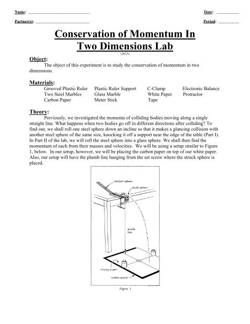
<strong>In</strong> Part II <strong>of</strong> the lab, we will roll the steel sphere into a glass sphere. We shall then find the<br />
momentum <strong>of</strong> each from their masses and velocities. We will be using a setup similar to Figure<br />
1, below. <strong>In</strong> our setup, however, we will be placing the carbon paper on top <strong>of</strong> our white paper.<br />
Also, our setup will have the plumb line hanging from the set screw where the struck sphere is<br />
placed.
Theory: (cont.)<br />
To find the velocities <strong>of</strong> the spheres, we shall use what we learned about projectile<br />
motion. We know that objects projected with different horizontal velocities from the edge <strong>of</strong> a<br />
table take the same time to fall to the floor. If we neglect air resistance, the horizontal<br />
component <strong>of</strong> their velocity remains unchanged and therefore the distance they go horizontally is<br />
proportional to their horizontal velocity. We can use this fact to measure the velocities <strong>of</strong> the<br />
spheres after they have collided.<br />
<strong>In</strong> Part I <strong>of</strong> the lab, the masses <strong>of</strong> the spheres are equal. Their distances traveled are<br />
indicative <strong>of</strong> both the velocity and momentum vectors. You will add the two momentum vectors<br />
graphically on your paper, placing the tail <strong>of</strong> the momentum vector <strong>of</strong> the target ball at the head<br />
<strong>of</strong> the momentum vector <strong>of</strong> the incident sphere.<br />
<strong>In</strong> Part II <strong>of</strong> the lab, the masses <strong>of</strong> the spheres are unequal. As a result, the distances<br />
traveled are still indicative <strong>of</strong> velocity vectors, but not <strong>of</strong> momentum vectors. The easiest way to<br />
make the distance vectors represent momentum vectors is to find the relative masses <strong>of</strong> the<br />
spheres. For example, if the mass <strong>of</strong> the marble is one-third that <strong>of</strong> the incident steel sphere, you<br />
can convert the distance vectors to momentum vectors by making the distance vector <strong>of</strong> the<br />
marble one-third as long and leaving the initial and final distance vectors <strong>of</strong> the steel sphere<br />
unchanged. Since momentum equals mass times velocity, these vectors now represent<br />
momentum vectors.<br />
Procedure:<br />
1. Mass the steel sphere and marble.<br />
2. Obtain four pieces <strong>of</strong> plain white paper. Tape the pages together as shown below to<br />
form a "quad-sheet".<br />
3. Secure the plastic ruler support to the lab table using the C-clamp.<br />
4. Unwrap the plumb line, which is a line (as <strong>of</strong> cord) that has at one end a weight (as a<br />
plumb bob) and is used especially to determine verticality, from the ruler support and<br />
check to see that the plumb bob is not resting on the ground. The bob should hang<br />
just above the floor. (Figure 1)<br />
5. Place the quad-sheet on the floor so that the short edge is about two centimeters<br />
behind the plumb line. Tape the paper to the floor.
Procedure: (cont.)<br />
6. The ruler support contains a set screw. This functions as a holder for the target<br />
sphere. The angle <strong>of</strong> the set screw can be varied relative to the groove on the ruler.<br />
Check to see that the set screw on your ruler support is at an angle (not straight in<br />
line) with the ruler groove. If it is not at an angle to the ruler groove, then move the<br />
set screw to some angle. Just take care not to create an angle so large that the<br />
incident sphere will not come into contact with the target sphere.<br />
7. The plumb line is attached to the set screw. Mark the location <strong>of</strong> the bob on your<br />
quad-sheet with a pencil. <strong>Lab</strong>el this mark, B. This mark will represent the location <strong>of</strong><br />
the target ball upon collision.<br />
8. The position <strong>of</strong> the incident sphere can be found by using the diameter <strong>of</strong> the steel<br />
marble. Place one <strong>of</strong> the steel marbles on the quad-sheet where you made the mark<br />
labeled B. Position one end <strong>of</strong> the marble at B and make a mark at a diagonal in the<br />
direction <strong>of</strong> the groove <strong>of</strong> the ruler. This second mark will be labeled A.<br />
A<br />
One Ball<br />
Diameter<br />
B<br />
9. Place the carbon paper face-down over the white paper. Do not tape the carbon<br />
paper down.<br />
10. For the first set <strong>of</strong> five runs, you will only use one metal ball. Using a ruler, release<br />
the steel ball from the top <strong>of</strong> the ramp. Repeat 5X. (Make sure that the ball does not<br />
hit the C-clamp or the set screw.)
Procedure: (cont.)<br />
A<br />
B<br />
11. For each <strong>of</strong> next five runs, place the second ball on the dimpled screw prior to<br />
releasing the first ball. Once again, use a ruler to release the first ball from the top <strong>of</strong><br />
the ramp. Be sure that both balls are marking the quad-sheet. This will complete Part<br />
I <strong>of</strong> the lab.<br />
A<br />
B<br />
12. <strong>In</strong> Part II <strong>of</strong> the lab, you will repeat all the steps in Part I with the exception that you<br />
will roll the steel sphere into the glass marble instead <strong>of</strong> a second steel sphere. You<br />
will need to use a new quad-sheet. Be sure to make your A and B marks.<br />
Data:<br />
1. Mass <strong>of</strong> either steel sphere __________________________ kg.<br />
2. Mass <strong>of</strong> the marble _______________________________ kg.<br />
3. The rest <strong>of</strong> the data will be collected on your two quad sheets.<br />
Analysis and Questions: (Answer in the space provided. Be sure to show your<br />
calculations.)<br />
1. Because your quad-sheets contain your data, make sure one member <strong>of</strong> your group<br />
turns in the quad-sheets with their lab.<br />
2. Take out the quad-sheet you used in Part I <strong>of</strong> the lab. This is the one in which you ran<br />
a steel sphere into another steel sphere.
Analysis and Questions: (cont.)<br />
3. Draw circles around the three sets <strong>of</strong> five data points.<br />
A<br />
B<br />
4. Mark a small X in the center in each <strong>of</strong> the circles you just drew.<br />
5. Draw a vector representing the incident sphere's velocity before collision. <strong>Lab</strong>el the<br />
vector (v A1 ), and measure its length in centimeters. Write both the label and the<br />
measurement next to the vector on the quad-sheet.<br />
x<br />
A<br />
B<br />
v A1<br />
x<br />
x<br />
6. Draw a vector representing the incident sphere's velocity after collision. <strong>Lab</strong>el the<br />
vector (v A2 ), and measure its length in centimeters. Write both the label and the<br />
measurement next to the vector on the quad-sheet.<br />
x<br />
v A2<br />
A<br />
B<br />
v A1<br />
x<br />
x
Analysis and Questions: (cont.)<br />
7. Draw a vector representing the target sphere's velocity after collision. <strong>Lab</strong>el the vector<br />
(v B2 ), and measure its length in centimeters. Write both the label and the<br />
measurement next to the vector on the quad-sheet.<br />
x<br />
v A2<br />
A<br />
B<br />
v A1<br />
x<br />
v B2<br />
x<br />
8. Using your Part I quad-sheet, intersect vectors (v A2 ) and (v B2 ). You will need to<br />
trace lines backwards from these two vectors until they intersect.<br />
x<br />
v A2<br />
A<br />
B<br />
v A1<br />
x<br />
v B2<br />
x<br />
9. Using a protractor, measure the angle formed between the vectors (v A2 ) and (v B2 ).<br />
Write this angle on your Part I quad-sheet.<br />
x<br />
v A2<br />
A<br />
B<br />
v A1<br />
x<br />
v B2<br />
x
Analysis and Questions: (cont.)<br />
10. Take the angle you just measured, along with the length <strong>of</strong> vector (v B2 ) you<br />
measured earlier and add (v B2 ) to (v A2 ). You will need to use your protractor and<br />
meter stick for this step.<br />
x<br />
v A2<br />
v B2<br />
A<br />
B<br />
v A1<br />
x<br />
v B2<br />
x<br />
11. Theoretically, the two velocity vectors after collision (v A2 ) and (v B2 ), which added<br />
together represent the final momentum <strong>of</strong> the system, should add up to the incident<br />
velocity vector (v A1 ), which represents the initial momentum <strong>of</strong> the system. If the<br />
vectors (v A2 ) and (v B2 ) did not add up perfectly, then you will calculate the percent<br />
error. To accomplish this, draw a dashed line from the tip <strong>of</strong> the (v B2 ) vector you<br />
just drew to the end <strong>of</strong> (v A1 ). Measure the length <strong>of</strong> this dashed line and write it on<br />
the quad-sheet.<br />
x<br />
v A2<br />
v B2<br />
A<br />
x<br />
B<br />
v A1<br />
v B2<br />
x<br />
% Difference =<br />
12. Take the distance <strong>of</strong> the dashed line, divide it by the length <strong>of</strong> vector (v A1 ) and<br />
multiply by 100. This will be your percent difference. Write these calculations on<br />
your Part I quad-sheet.
Analysis and Questions: (cont.)<br />
13. We will follow a very similar process with your quad-sheet from Part II <strong>of</strong> the lab.<br />
We will need to change a few things, however, because this section <strong>of</strong> the lab deals<br />
with spheres <strong>of</strong> unequal mass.<br />
14. Take your quad-sheet from Part II and follow Analysis and Questions steps three<br />
through nine.<br />
15. <strong>In</strong>stead <strong>of</strong> directly adding vector (v B2 ) to (v A2 ), as in Part I <strong>of</strong> the lab, we will need<br />
to take into account the smaller mass <strong>of</strong> the glass marble. To do this, you multiply<br />
the length <strong>of</strong> (v B2 ) by the ratio <strong>of</strong> the mass <strong>of</strong> the glass marble to the mass <strong>of</strong> the<br />
steel marble. The equation is written below.<br />
Length <strong>of</strong> v<br />
B2<br />
<br />
Mass<br />
Mass<br />
Glass Marble<br />
Steel Sphere<br />
Draw the converted (v B2 ) vector on top <strong>of</strong> the old one. It will be shorter than the<br />
original. Be sure to write the conversion calculations on your Part II quad-sheet.<br />
x<br />
v A2<br />
A<br />
B<br />
v A1<br />
x<br />
v B2<br />
x<br />
16. Follow Analysis and Questions steps ten through twelve in adding the converted<br />
(v B2 ) vector to (v A2 ) and calculating the % Difference. Be sure to include all<br />
necessary calculations, vectors, etc... on your Part II quad-sheet.<br />
17. Using the information in the table above, do you think we had a closed system in our<br />
experiment Justify your answer.<br />
______________________________________________________________________________<br />
______________________________________________________________________________<br />
______________________________________________________________________________<br />
______________________________________________________________________________<br />
______________________________________________________________________________