EFI SYSTEM
EFI SYSTEM
EFI SYSTEM
- No tags were found...

Create successful ePaper yourself
Turn your PDF publications into a flip-book with our unique Google optimized e-Paper software.
TO INDEX<br />
EF<br />
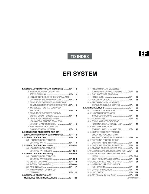
<strong>EFI</strong> <strong>SYSTEM</strong><br />
1. GENERAL PRECAUTIONARY MEASURES ......... EF–-1 2<br />
1.1 INSTRUCTIONS ON USE OF THIS<br />
SERVICE MANUAL ........................................ EF–-1 2<br />
1.2 HANDLING INSTRUCTIONS ON CATALYTIC<br />
CONVERTER-EQUIPPED VEHICLES ............ EF–-1 3<br />
1.3 ITEMS TO BE OBSERVED WHEN MOBILE<br />
COMMUNICATION <strong>SYSTEM</strong> IS MOUNTED .. EF–-1 3<br />
1.4 IMMOBILIZER <strong>SYSTEM</strong>-EQUIPPED<br />
VEHICLES ..................................................... EF–-1 4<br />
1.5 ITEMS TO BE OBSERVED DURING<br />
<strong>SYSTEM</strong> CIRCUIT CHECK ............................ EF–-1 4<br />
1.6 ITEMS TO BE OBSERVED WHEN<br />
USING OBD II GENERIC SCAN TOOL<br />
OR DS-21 DIAGNOSIS TESTER .................... EF–-1 6<br />
1.7 HANDLING INSTRUCTIONS ON<br />
ENGINE CONTROL <strong>SYSTEM</strong> ........................ EF–-1 6<br />
2. CONNECTING PROCEDURE FOR SST<br />
(<strong>EFI</strong> COMPUTER CHECK SUB-HARNESS) .......... EF–-1 8<br />
3. <strong>SYSTEM</strong> DESCRIPTION ........................................ EF–-1 9<br />
3.1 LOCATION OF ELECTRONIC<br />
CONTROL PARTS ......................................... EF–-1 9<br />
3. <strong>SYSTEM</strong> DESCRIPTION (S221) ............................ EF–13-1<br />
3.1 LOCATION OF ELECTRONIC<br />
CONTROL PARTS (S221) ............................. EF–13-1<br />
3. <strong>SYSTEM</strong> DESCRIPTION (M201) ............................ EF–13-4<br />
3.1 LOCATION OF ELECTRONIC<br />
CONTROL PARTS (M201) ............................. EF–13-4<br />
3.2 <strong>SYSTEM</strong> DIAGRAM ....................................... EF–-114<br />
3.2 <strong>SYSTEM</strong> DIAGRAM (S221) ........................... EF–16-1<br />
3.3 WIRING DIAGRAM ........................................ EF–-117<br />
3.4 ARRANGEMENT OF <strong>EFI</strong> ECU<br />
TERMINAL ..................................................... EF–-120<br />
4. GENERAL PRECAUTIONARY<br />
MEASURES IN ENGINE DIAGNOSIS ................... EF–-123<br />
4. 1 PRECAUTIONARY MEASURES<br />
FOR REPAIRS OF FUEL <strong>SYSTEM</strong>S ........... EF–-1 23<br />
4. 2 FUEL PRESSURE RELIEVING<br />
PROCEDURE ............................................ EF–-1 25<br />
4. 3 FUEL LEAK CHECK .................................. EF–-1 25<br />
4. 4 PRECAUTIONARY MEASURES<br />
DURING TROUBLE-SHOOTING ............... EF–-1 25<br />
5. ENGINE DIAGNOSIS ........................................... EF–-1 26<br />
5. 1 GENERAL INFORMATION ........................ EF–-1 26<br />
5. 2 HOW TO PROCEED WITH<br />
TROUBLE-SHOOTING .............................. EF–-1 32<br />
5. 3 INQUIRY SHEET ........................................ EF–-1 40<br />
5. 4 DTC CHART SPECIFICATIONS<br />
FOR M101, M201, J102 AND S221 ........... EF–-1 41<br />
5. 5 FAIL-SAFE FUNCTION<br />
FOR M101, M201, J102 AND S221 ........... EF–-1 45<br />
5. 6 MATRIX TABLE FOR TROUBLE-<br />
SHOOTING ACCORDING TO<br />
MALFUNCTIONING PHENOMENA ........... EF–-1 47<br />
5. 7 CHECKING PROCEDURE FOR<br />
COMMON ITEMS IN CHART ..................... EF–-1 48<br />
5. 8 CHECKING PROCEDURE FOR DTC ........ EF–-1 52<br />
5. 9 ERASING PROCEDURE FOR DTC ........... EF–-1 57<br />
5.10 BASIC ENGINE CHECK FLOW CHART .... EF–-1 59<br />
5.10 BASIC ENGINE CHECK FLOW CHART<br />
(S221) ........................................................ EF– 59-1<br />
5.11 SCAN TOOL DATA (ECU DATA) .............. EF–-1 62<br />
5.12 CHECK OF ECU AND ITS CIRCUIT .......... EF–-1 64<br />
5.13 INSPECTION PROCEDURE FOR<br />
FUEL <strong>SYSTEM</strong> ........................................... EF–-1 67<br />
5.14 CIRCUIT INSPECTION .............................. EF–-1 71<br />
5.15 UNIT CHECK ............................................. EF–-1184<br />
5.16 SST (Special Service Tools) ...................... EF–-1189<br />
JEF00001-00000
EF–2<br />
1. GENERAL PRECAUTIONARY MEASURES<br />
1.1 INSTRUCTIONS ON USE OF THIS SERVICE MANUAL<br />
This service manual has been compiled in such a way that the manual may be used both in regions where<br />
the type certification is implemented based on the EC exhaust emission approval, and other regions.<br />
Hence, with regard to the assignment, reading, erasing of trouble codes and those steps of checks, repairs<br />
and confirmation, the service manual contains the procedures for both cases; One is a procedure that uses<br />
the DS-21 diagnosis tester or the OBD II generic scan tool, and the other is a procedure that does not use<br />
this tester or tool.<br />
Therefore, the following instructions given below must be observed.<br />
1. About Use of DS-21 Diagnosis Tester or OBD II Generic Scan Tool<br />
• Regions where type certification is implemented based on EC exhaust emission approval<br />
Make sure to use the DS-21 diagnosis tester or the OBD II generic scan tool.<br />
• Other regions<br />
You may use or not use the DS-21 diagnosis tester or the OBD II generic scan tool.<br />
You may perform the operation, employing whichever method that will be easier to you.<br />
2. Instructions To Be Followed Concerning Trouble Codes<br />
Trouble codes, such as P0105/31 (4-digit code/2-digit code) are posted additionally.<br />
• Regions where type certification is implemented based on EC exhaust emission approval<br />
Make sure to use only 4-digit trouble codes (e.g. P0105) which have been assigned according<br />
to the ISO regulations.<br />
• Other regions<br />
You may perform the operation using the 4-digit code, employing the DS-21 diagnosis tester or<br />
the OBD II generic scan tool. Or you may perform the operation using the 2-digit codes<br />
(e.g. 31), without the use of the tester or tool.<br />
You may perform the operation, employing whichever method that will be easier to you.<br />
NOTE:<br />
• The OBD II generic scan tool means a scan tool complying with the ISO 14230 (KWP2000) format.<br />
• In cases where the OBD II generic scan tool is employed, not all malfunction codes (4-digit codes)<br />
can be read out. It should be noted that only those trouble codes in which “zero” follows after “P”, for<br />
example, P0XXX, can be read out.<br />
• The accuracy of the 2-digit codes in diagnosing malfunctioning components is slightly inferior to that<br />
of the 4-digit codes.<br />
• Hereinafter, those regions where the type certification is implemented based on the EC exhaust<br />
emission approval, is referred to as the “EU specifications.”<br />
JEF00337-00000
EF–3<br />
1.2 HANDLING INSTRUCTIONS ON CATALYTIC CONVERTER-EQUIPPED VEHICLES<br />
WARNING:<br />
• When a great amount of unburnt gas is admitted into the catalytic converter, overheating is prone to<br />
occur, resulting in a fire hazard.<br />
To avoid such trouble in advance, be certain to observe the following precautions. Also, be sure to<br />
explain such precautions to your customers.<br />
1. Use only unleaded gasoline to catalytic converter-equipped vehicles.<br />
2. Avoid idling the engine for a prolonged length of time.<br />
Do not run the engine continuously at idle speed for more than 20 minutes.<br />
WARNING:<br />
• Immediately check and repair the vehicle if the fast idle speed or idle speed is unstable or the system<br />
exhibits malfunction. Failure to observe this warning may result in a fire hazard.<br />
3. Be sure to observe the following points when performing the spark jump tests.<br />
(1) The spark jump test must be limited to cases where such test is absolutely necessary. Also, be sure<br />
to finish the test in the shortest possible time.<br />
(2) Never race the engine during the test.<br />
(3) Be sure to shut off the fuel supply when performing the spark jump test in advance.<br />
4. Do not run the engine when the fuel tank becomes nearly empty.<br />
Failure to observe this caution will cause misfiring. Also, it will apply excessive load to the catalytic converter,<br />
even leading to catalyst damage.<br />
5. Be sure to avoid coasting with the ignition switch turned OFF. Moreover, be certain to avoid applying the<br />
brake for a prolonged period of time.<br />
6. Do not dispose of the waste catalyst along with parts contaminated with gasoline or oil.<br />
JEF00002-00000<br />
1.3 ITEMS TO BE OBSERVED WHEN MOBILE COMMUNICATION <strong>SYSTEM</strong> IS<br />
MOUNTED<br />
For those motor vehicles equipped with a mobile communication system, such as a bidirectional wireless<br />
telephone and cellular phone, be sure to observe the following precautionary measures.<br />
1. Install the antenna as far away as possible from the ECU and sensors of the electronically-controlled<br />
system of the vehicle.<br />
2. The wire of the antenna should be routed at least 30 cm away from the ECU and sensors of the electronically-controlled<br />
system of the vehicle. For details concerning the arrangement of the ECU and sensors,<br />
refer to the arrangement diagram of the components in the relevant section.<br />
3. Do not wind the antenna feeder line together with other wires. Avoid routing the antenna feeder in parallel<br />
with other harnesses whenever possible.<br />
4. The antenna and feeder line should be properly adjusted.<br />
5. Never install a strong mobile communication system.<br />
JEF00003-00000
EF–4<br />
1.4 IMMOBILIZER <strong>SYSTEM</strong>-EQUIPPED VEHICLES<br />
1. The immobilizer system is formed by communication between the Immobilizer ECU and the <strong>EFI</strong> ECU by<br />
means of the rolling code. The rolling code will be automatically retained both in the immobilizer ECU<br />
and in the <strong>EFI</strong> ECU when the engine is started once with the key of the immobilizer system. The engine<br />
will not start if the rolling code in the immobilizer ECU and <strong>EFI</strong> ECU are not identical. Therefore, the engine<br />
will not start when using the <strong>EFI</strong> ECU which was mounted before on another vehicle with the immobilizer<br />
system without resetting the rolling code.<br />
2. When the <strong>EFI</strong> ECU of a vehicle equipped with the immobilizer system was replaced, based on the results<br />
of the trouble shooting, and related troubles have been remedied, it is impossible, due to its construction,<br />
to confirm that the malfunction was caused by the former <strong>EFI</strong> ECU by installing the <strong>EFI</strong> ECU<br />
again. Incidentally, this confirmation is possible in the case of vehicles without the immobilizer system.<br />
Therefore, it is not necessary to install the former <strong>EFI</strong> ECU again to carry out the reconfirmation.<br />
In the case of vehicles without the immobilizer system, be sure to carry out this re-installation and reconfirmation.<br />
3. In the case of vehicles equipped with the immobilizer system, once the engine is started for the confirmation<br />
test, etc. after the malfunction has been remedied, that <strong>EFI</strong> ECU can not be used for other vehicles<br />
with the immobilizer system, unless a measure is taken.<br />
NOTE:<br />
• When you would like to use each ECU of the vehicle concerned on vehicles equipped with other immobilizer<br />
system, initialize the ECU, using the diagnosis tester (DS-21), before removing the ECU<br />
from the vehicle. Then, remove the ECU and install it on another vehicle. If you perform the key registration,<br />
using the master key of this vehicle, each ECU can be used separately or as a set.<br />
• When the <strong>EFI</strong> ECU is to be replaced with a new one, it is possible to start the engine by using the<br />
master key with the terminal T for immobilizer ECU (ECU-T) of the data link connector grounded with<br />
a jump wire.<br />
• Please refer to Section BE of the service manual.<br />
JEF00004-00000<br />
1.5 ITEMS TO BE OBSERVED DURING <strong>SYSTEM</strong><br />
CIRCUIT CHECK<br />
1. Before connecting and disconnecting the connectors and<br />
terminals, be sure to turn OFF the ignition switch or disconnect<br />
the negative (–) terminal from the battery.<br />
Otherwise, the harness is judged to have an open wire,<br />
and the fail-safe function will be applied.<br />
On the other hand, when the negative (–) terminal of the<br />
battery is disconnected, the diagnosis code will be<br />
erased. Therefore, if it is necessary to confirm the diagnosis<br />
code, be sure to perform the confirmation in advance.<br />
2. When disconnecting the connector, never pull the harness.<br />
Rather, hold the connector properly with the connector<br />
unlocked and pull it.<br />
When connecting the connector, be sure to positively insert<br />
the connector, until you hear a clicking sound when<br />
the lock is engaged.<br />
IG “OFF”<br />
JEF00005-00001<br />
JEF00006-00002
EF–5<br />
3. Do not directly touch the terminals of parts which incorporate<br />
a microcomputer.<br />
4. When a test probe is applied to the terminal to which a<br />
voltage is applied, care must be exercised so that two test<br />
probes may not come in contact with each other, so that<br />
short circuit may not take place.<br />
5. When the connector is connected to the ECU, never connect<br />
an ohmmeter between the ECU connector and the<br />
sensor or actuator. Failure to observe this caution may<br />
damage the ECU or sensor or actuator.<br />
Ω<br />
JEF00007-00003<br />
6. When a test probe is applied to the connector, be sure to<br />
bring it from the rear side (harness side) of the connector.<br />
In the case of connectors where it is impossible to apply a<br />
test probe from the rear side, such as water-proof connectors,<br />
apply the test probe from the connector side. At this<br />
time, be very careful not to bend the male terminal of the<br />
connector or open the female terminal.<br />
JEF00008-00004<br />
7. Be sure to use a voltmeter/ohmmeter whose internal impedance<br />
is at least 10 kΩ/V.<br />
When a voltmeter/ohmmeter whose internal impedance is<br />
less than 10 kΩ/V is used, it may cause the ECU to malfunction<br />
or give a wrong evaluation.<br />
8. When checking the terminal for the connecting condition,<br />
be sure to check the male terminal for a bend and the female<br />
terminal for an excessive opening. Furthermore,<br />
check both terminals for locking (looseness), rust formation,<br />
dust adhesion, etc.<br />
9. Prior to the measurement of the voltage of each terminal,<br />
make sure that the battery voltage is 11 V or more. If the<br />
terminal voltage is checked with a low battery voltage, it<br />
may lead to a wrong diagnosis.<br />
Ω<br />
OC V A<br />
500<br />
200<br />
0<br />
00<br />
AC V<br />
BTEST<br />
100<br />
70<br />
50<br />
10<br />
2<br />
50 40<br />
100<br />
20<br />
4<br />
30<br />
20<br />
150<br />
30<br />
5<br />
15<br />
200<br />
40<br />
8<br />
10<br />
5<br />
250<br />
50<br />
10<br />
AC V<br />
BTEST<br />
20 KΩ/V DC 10 KΩ/V AC<br />
JEF00009-00005<br />
0<br />
Ω<br />
OC V A<br />
JEF00010-00006<br />
V<br />
JEF00011-00007
EF–6<br />
1.6 ITEMS TO BE OBSERVED WHEN USING OBD II GENERIC SCAN TOOL OR DS-21<br />
DIAGNOSIS TESTER<br />
CAUTION:<br />
For enhanced safety, be sure to observe the following points:<br />
• Before using the OBD II generic scan tool or the DS-21 diagnosis tester, be sure to thoroughly<br />
read the instruction manual of the OBD II generic scan tool or the instruction manual of the DS-21<br />
diagnosis tester.<br />
• When driving the vehicle with the OBD II generic scan tool or the DS-21 diagnosis tester connected<br />
to the vehicle, route the cables in such a way that they may not interfere with the driving.<br />
(That is to say, the cables should be routed away from the feet, pedals, steering wheel and shift<br />
lever.)<br />
• When performing the test driving, using the OBD II generic scan tool or the DS-21 diagnosis<br />
tester, two persons are needed. One person drives the vehicle, while the other person operates<br />
the OBD II generic scan tool or the DS-21 diagnosis tester.<br />
JEF00012-00000<br />
1.7 HANDLING INSTRUCTIONS ON ENGINE CONTROL <strong>SYSTEM</strong><br />
1. The ECU, sensors, etc. are precision parts. Be very careful not to give strong impacts to those parts<br />
during the installation and removal. Never use those parts to which impacts have been given (for example,<br />
in cases where the parts were dropped on the floor).<br />
2. When the test is carried out on a rainy day or the vehicle is washed, care must be exercised so that no<br />
water may be admitted and the ECU, connectors, sensors, actuators, etc. may not get wet.<br />
3. Never disconnect the connector from the battery terminal while the engine is running. At the moment<br />
when the connector is disconnected from the battery terminal, a great counter electromotive force (approx.<br />
100 V) may be generated, thus damaging the ECU.<br />
4. Never connect the connectors to the wrong terminals of the battery. Failure to observe this caution may<br />
break the inside of the battery instantly.<br />
JEF00013-00000<br />
5. Never remove the cover from the ECU proper or the<br />
bracket on the ECU proper side. Furthermore, do not<br />
touch the attaching screws.<br />
JEF00014-00009
EF–7<br />
6. In cases where the ECU was judged to be malfunctioning<br />
and the vehicle has been remedied by replacing it, install<br />
the removed ECU (which has been judged to be malfunctioning)<br />
again to confirm that the original malfunction is reproduced.<br />
Then, the ECU can be finally judged to have<br />
been malfunctioning.<br />
JEF00015-00000<br />
7. Tachometer connection<br />
Connect the tachometer probe to the measuring terminal<br />
of the SST connecter.<br />
CAUTION:<br />
• This does not apply if your tachometer is a pick-up<br />
type.<br />
• Never allow the tachometer probe to touch the ground,<br />
for it could result in damage to the ignitor and/or ignition<br />
coil.<br />
• Some kinds of tachometers may not be suited for the<br />
ignition system of the vehicle. Therefore, ensure that<br />
your tachometer is compatible with the ignition system<br />
of the vehicle.<br />
SST: 09991-87404-000<br />
SST<br />
connector<br />
Tacho-meter<br />
terminal<br />
Earth<br />
SST<br />
JEF00016-00010
EF–8 Revision 2<br />
2. CONNECTING PROCEDURE FOR SST<br />
(<strong>EFI</strong> COMPUTER CHECK SUB-<br />
HARNESS)<br />
When the ECU terminal voltage is measured with the ECU<br />
connector connected to the engine ECU, connect the SST, following<br />
the procedure given below.<br />
NOTE:<br />
• The terminal number of the SST connector is the same<br />
as the ECU connector (page EF–20).<br />
1. Turn OFF the ignition switch. Or, disconnect the battery<br />
ground cable from the negative (–) terminal of the battery<br />
with the ignition switch turned OFF.<br />
Disconnect the battery ground cable from the negative (–)<br />
terminal of the battery.<br />
CAUTION:<br />
• Be sure to memorize the malfunction code before disconnecting<br />
the battery cable. Otherwise the malfunction<br />
code(s) will be erased by disconnecting the battery<br />
cable.<br />
Push<br />
Pull<br />
[M101, M201 & J102]<br />
Pull ( Except for M201 )<br />
IG “OFF”<br />
YEF00002-00001<br />
Push<br />
2. Remove the glove compartment sub assembly. [M101,<br />
M201 & J102]<br />
Remove the <strong>EFI</strong>-ECU cover [S221]<br />
[S221]<br />
YEF00003-00002<br />
3. Disconnect the wire harness connectors from the <strong>EFI</strong> ECU<br />
connectors at the cowl side of the passenger seat.<br />
4. Connect the following SST between the wire harness connectors<br />
and the <strong>EFI</strong> ECU connectors.<br />
SST: 09842-97203-000<br />
<strong>EFI</strong> ECU<br />
Wire<br />
harness<br />
YEF00004-00003<br />
Top<br />
5. Reconnect the battery ground cable to the negative (–)<br />
terminal of the battery.<br />
CAUTION:<br />
• When disconnecting or reconnecting the <strong>EFI</strong> ECU connectors,<br />
be sure to disconnect the battery ground cable<br />
from the negative (–) terminal of the battery with the ignition<br />
switch and all accessory switches in the off state.<br />
• When installing a new battery, care must be exercised<br />
not to mistake the battery polarity. Failure to observe<br />
this caution could cause ECU malfunction.<br />
• Before using the SST, be sure to check to see if short<br />
or open wire exists between the terminals of the SST.<br />
qwe<br />
!2!3!4<br />
@3@4@5<br />
#4#5#6<br />
$5$6$7<br />
%6%7%8<br />
^7^8^9<br />
&8&9*0<br />
o!0!1<br />
@0@1@2<br />
#1#2#3<br />
$2$3$4<br />
%3%4%5<br />
^4^5^6<br />
&5&6&7<br />
*6*7*8<br />
SST<br />
SST<br />
connector<br />
Arrow A<br />
*9(0(1<br />
<br />
YEF00005-00004
EF–9<br />
3. <strong>SYSTEM</strong> DESCRIPTION<br />
3.1 LOCATION OF ELECTRONIC CONTROL PARTS<br />
3.1.1 FOR EU SPECIFICATIONS OF M101<br />
Valve for ISC<br />
Data link connector<br />
Manifold absolute pressure sensor<br />
Linear throttle sensor<br />
Ignition coil<br />
Front O2 sensor<br />
(Bank 1 sensor 1)<br />
Fuel pump<br />
Crank angle sensor<br />
Relay block<br />
Engine control<br />
unit (ECU)<br />
Injector<br />
Intake air temperature sensor<br />
Engine coolant<br />
temperature sensor<br />
Rear O2 sensor<br />
(Bank 1 sensor 2)<br />
Neutral start switch<br />
(Only for A/T)<br />
Ignitor unit<br />
Cam angle sensor<br />
VSV for EVAP<br />
JEF00021-00014
EF–10<br />
3.1.2 FOR EU SPECIFICATIONS OF J102<br />
Intake air temperature sensor<br />
VSV for EVAP<br />
Manifold absolute<br />
pressure sensor<br />
Vehicle speed sensor<br />
(Low-grade vehicles except A/T vehicle)<br />
Ignitor unit<br />
Cam angle sensor<br />
Valve for ISC<br />
Relay block<br />
Linear throttle<br />
sensor<br />
Fuel pump<br />
Oil control valve<br />
Engine control<br />
unit (ECU)<br />
Injector<br />
Ignition coil<br />
Crank angle sensor<br />
Front O2 sensor<br />
(Bank 1 sensor 1)<br />
Neutral start switch<br />
(Only for A/T)<br />
Engine coolant<br />
temperature sensor<br />
Rear O2 sensor<br />
(Bank 1 sensor 2)<br />
Data link connector<br />
(DLC)<br />
JEF00022-00015
EF–11<br />
3.1.3 FOR AUS AND GENERAL SPECIFICATIONS OF M101<br />
Valve for ISC<br />
Data link connector<br />
Manifold absolute pressure sensor<br />
Linear throttle sensor<br />
Ignition coil<br />
O2 sensor<br />
Fuel pump<br />
Crank angle sensor<br />
Relay block<br />
Engine control<br />
unit (ECU)<br />
Injector<br />
Intake air temperature sensor<br />
Engine coolant<br />
temperature sensor<br />
Neutral start switch<br />
(Only for A/T)<br />
Knock sensor<br />
Cam angle sensor<br />
VSV for EVAP<br />
JEF00023-00016
EF–12<br />
3.1.4 FOR AUS AND GENERAL SPECIFICATIONS OF J102<br />
Intake air temperature sensor<br />
VSV for EVAP<br />
Manifold absolute<br />
pressure sensor<br />
Vehicle speed sensor<br />
(Low-grade vehicles except A/T vehicle)<br />
Cam angle sensor<br />
Valve for ISC<br />
Relay block<br />
Linear throttle<br />
sensor<br />
Fuel pump<br />
Oil control valve<br />
Engine control<br />
unit (ECU)<br />
Injector<br />
Ignition coil<br />
O2 sensor<br />
Crank angle sensor<br />
Knock sensor<br />
Neutral start switch<br />
(Only for A/T)<br />
Engine coolant<br />
temperature sensor<br />
Data link connector<br />
(DLC)<br />
JEF00024-00017
EF–13<br />
3.1.5 FOR LEADED SPECIFICATIONS OF J102<br />
Intake air temperature sensor<br />
VSV for EVAP<br />
Manifold absolute<br />
pressure sensor<br />
Vehicle speed sensor<br />
(Low-grade vehicles except A/T vehicle)<br />
Valve for ISC<br />
Engine control<br />
unit (ECU)<br />
Linear throttle<br />
sensor<br />
Oil control valve<br />
Injector<br />
Ignition coil<br />
Crank angle sensor<br />
Knock sensor<br />
Cam angle<br />
sensor<br />
Engine coolant<br />
temperature sensor<br />
Neutral start switch<br />
(Only for A/T)<br />
A/F adjuster<br />
Data link connector<br />
(DLC)<br />
Fuel pump<br />
Relay block<br />
JEF00025-00018
EF–13-1 Revision 1<br />
3. <strong>SYSTEM</strong> DESCRIPTION (S221)<br />
3.1 LOCATION OF ELECTRONIC CONTROL PARTS (S221)<br />
3.1.6 FOR EU SPECIFICATIONS OF S221<br />
Vehicle speed<br />
sensor<br />
Data link<br />
connector<br />
(DLC)<br />
Engine control unit<br />
(ECU)<br />
Linear throttle sensor<br />
Manifold absolute<br />
pressure sensor<br />
Intake air temp.<br />
sensor<br />
Oil control<br />
valve<br />
Crank angle sensor<br />
Engine coolant<br />
temperature<br />
sensor<br />
VSV for EVAP<br />
Cam angle<br />
sensor<br />
Injector<br />
Neutral start<br />
switch (Only for A/T)<br />
Fuel pump<br />
Rear O2 sensor<br />
(Bank 1 sensor 2)<br />
Ignitor unit<br />
Front O2 sensor<br />
(Bank 1 sensor 1)<br />
Relay block<br />
Ignition coil<br />
sEF00006-00005
Revision 1<br />
EF–13-2<br />
3.1.7 FOR AUS AND GENERAL SPECIFICATIONS OF S221<br />
Vehicle speed<br />
sensor<br />
Data link<br />
connector<br />
(DLC)<br />
Engine control unit<br />
(ECU)<br />
Knock sensor<br />
Linear throttle sensor<br />
Manifold absolute<br />
pressure sensor<br />
Engine coolant<br />
temperature<br />
sensor<br />
Intake air temp.<br />
sensor<br />
VSV for EVAP<br />
Cam angle<br />
sensor<br />
Injector<br />
Neutral start<br />
switch (Only for A/T)<br />
Fuel pump<br />
Oil control<br />
valve<br />
Crank angle sensor<br />
O2 sensor<br />
Relay block<br />
Ignition coil<br />
sEF00007-00006
EF–13-3 Revision 1<br />
3.1.8 FOR LEADED SPECIFICATIONS OF S221<br />
Vehicle speed<br />
sensor<br />
A/F adjuster<br />
Data link<br />
connector<br />
(DLC)<br />
Engine control unit<br />
(ECU)<br />
Knock sensor<br />
Manifold absolute<br />
pressure sensor<br />
Linear throttle sensor<br />
Intake air temp.<br />
sensor<br />
VSV for EVAP<br />
Injector<br />
Oil control<br />
valve<br />
Crank angle sensor<br />
Relay block<br />
Ignition coil<br />
Engine coolant<br />
temperature<br />
sensor<br />
Cam angle<br />
sensor<br />
Neutral start<br />
switch (Only for A/T)<br />
Fuel pump<br />
sEF00008-00007
Revision 2<br />
EF–13-4<br />
3. <strong>SYSTEM</strong> DESCRIPTION (M201)<br />
3.1 LOCATION OF ELECTRONIC CONTROL PARTS (M201)<br />
3.1.9 FOR EU SPECIFICATIONS OF M201<br />
Manifold absolute<br />
pressure sensor<br />
Engine control<br />
unit (ECU)<br />
Valve for ISC<br />
Data link connector<br />
Linear throttle sensor<br />
Ignition coil<br />
Front oxygen<br />
sensor<br />
(Bank 1 sensor 1)<br />
Crank angle<br />
sensor<br />
Injector<br />
Engine coolant<br />
temperature sensor<br />
Rear oxygen sensor<br />
(Bank 1 sensor 2)<br />
Neutral start switch<br />
(Only for A/T)<br />
Relay block<br />
Intake air temperature sensor<br />
VSV for purge<br />
Ignitor unit<br />
Cam angle sensor<br />
Fuel pump<br />
YEF00006-00005
EF–13-5 Revision 2<br />
3.1.10 FOR AUS AND GENERAL SPECIFICATIONS OF M201<br />
Manifold absolute<br />
pressure sensor<br />
Linear throttle<br />
sensor<br />
Ignition coil<br />
Engine control<br />
Valve for ISC<br />
unit (ECU)<br />
Data link connector<br />
oxygen sensor<br />
Crank angle<br />
sensor<br />
Injector<br />
Fuel pump<br />
Relay block<br />
Intake air temperature sensor<br />
VSV for purge<br />
Engine coolant<br />
temperature sensor<br />
Neutral start switch<br />
(Only for A/T)<br />
Knock sensor<br />
Cam angle sensor<br />
YEF00007-00006
EF–14 Revision 2<br />
3.2 <strong>SYSTEM</strong> DIAGRAM<br />
3.2.1 FOR EU SPECIFICATIONS OF M101, M201 and J102<br />
Intake air temp. sensor<br />
Air cleaner<br />
Linear throttle sensor<br />
Throttle body<br />
Valve for ISC<br />
Ignition coil<br />
Manifold absolute<br />
pressure sensor<br />
VSV for purge<br />
Ignitor unit<br />
(With ion<br />
current<br />
detection)<br />
PCV valve<br />
Surge<br />
tank<br />
IMB ECU<br />
Data link connector<br />
Vehicle speed sensor<br />
<strong>EFI</strong> ECU<br />
(Atmospheric pressure sensor built-in)<br />
A/T ECU<br />
+B<br />
Malfunction<br />
indicator<br />
lamp<br />
Neutral start switch<br />
(Only for A/T)<br />
Front O2 sensor heater<br />
Front O2 sensor<br />
(Bank 1 sensor 1)<br />
Crank angle sensor<br />
Injector<br />
Charcoal canister<br />
Oil control valve<br />
Cam angle sensor<br />
DVVT controller<br />
(Dynamic variable valve<br />
timing controller)<br />
Engine coolant<br />
temperature sensor<br />
Rear O2 sensor heater<br />
Rear O2 sensor<br />
(Bank 1 sensor 2)<br />
Three-way catalyst<br />
YEF00009-00037
Revision 2<br />
EF–15<br />
3.2.2 FOR AUS AND GENERAL SPECIFICATIONS OF M101, M201 and J102<br />
Intake air temp. sensor<br />
Air cleaner<br />
Linear throttle sensor<br />
Throttle body<br />
Valve for ISC<br />
Ignition coil<br />
Manifold absolute<br />
pressure sensor<br />
VSV for purge<br />
(In case of M101<br />
& M201)<br />
PCV valve<br />
Surge<br />
tank<br />
(In case of J102)<br />
Charcoal canister<br />
IMB ECU<br />
Data link connector<br />
Vehicle speed sensor<br />
<strong>EFI</strong> ECU<br />
A/T ECU<br />
+B<br />
Malfunction<br />
indicator<br />
lamp<br />
Oil control valve<br />
Cam angle sensor<br />
Injector<br />
Neutral start switch<br />
(Only for A/T)<br />
O2 sensor<br />
Knock<br />
sensor<br />
Crank angle sensor<br />
DVVT controller<br />
(Dynamic variable valve<br />
timing controller)<br />
Engine coolant<br />
temperature sensor<br />
Three-way catalyst<br />
YEF00010-00039
EF–16<br />
3.2.3 FOR LEADED SPECIFICATIONS OF J102<br />
Intake air temp. sensor<br />
Air cleaner<br />
Linear throttle sensor<br />
Throttle body<br />
Valve for ISC<br />
Ignition coil<br />
Manifold absolute<br />
pressure sensor<br />
VSV for purge<br />
PCV valve<br />
Surge<br />
tank<br />
Charcoal canister<br />
IMB ECU<br />
Data link connector<br />
Vehicle speed sensor<br />
<strong>EFI</strong> ECU<br />
A/T ECU<br />
A/F adjuster<br />
+B<br />
Oil control valve<br />
Cam angle sensor<br />
Malfunction<br />
indicator<br />
lamp<br />
Injector<br />
Neutral start switch<br />
(Only for A/T)<br />
Knock<br />
sensor<br />
Crank angle sensor<br />
DVVT controller<br />
(Dynamic variable valve<br />
timing controller)<br />
Engine coolant<br />
temperature sensor<br />
JEF00031-00022
Revision 1<br />
EF–16-1<br />
3.2 <strong>SYSTEM</strong> DIAGRAM (S221)<br />
3.2.4 FOR EU SPECIFICATIONS OF S221<br />
Ignition coil<br />
+B<br />
<strong>EFI</strong> ECU<br />
(Atmospheric pressure sensor built-in)<br />
Ignitor unit<br />
(With ion<br />
current<br />
detection)<br />
IMB ECU<br />
Data link connector<br />
Vehicle speed sensor<br />
Linear throttle sensor<br />
Intake air temp.<br />
sensor<br />
Throttle body<br />
Engine coolant<br />
temperature sensor<br />
Manifold absolute<br />
pressure sensor<br />
Surge tank<br />
Injector<br />
Oil control<br />
valve<br />
Air cleaner<br />
Cam angle sensor<br />
PCV valve<br />
Valve for ISC<br />
VSV for purge<br />
A/T ECU<br />
Crank angle<br />
sensor<br />
Three-way<br />
catalyst<br />
Charcoal<br />
canister<br />
Malfunction<br />
indicator<br />
lamp<br />
Neutral start switch<br />
(Only for A/T)<br />
DVVT controller<br />
(Dynamic variable valve<br />
timing controller)<br />
Front O2 sensor heater<br />
Front O2 sensor<br />
(Bank 1 sensor 1) Rear O2 sensor heater<br />
Rear O2 sensor<br />
(Bank 1 sensor 2)<br />
sEF00009-00008
EF–16-2 Revision 1<br />
3.2.5 FOR AUS AND GENERAL SPECIFICATIONS OF S221<br />
Ignition coil<br />
Injector<br />
Air cleaner<br />
<strong>EFI</strong> ECU<br />
IMB ECU<br />
Data link connector<br />
Vehicle speed sensor<br />
Oil control<br />
valve<br />
Cam angle sensor<br />
PCV valve<br />
Three-way<br />
catalyst<br />
Throttle body<br />
Linear throttle sensor<br />
Engine coolant<br />
temperature sensor<br />
Intake air temp.<br />
sensor<br />
Manifold absolute<br />
pressure sensor<br />
Surge tank<br />
Valve for ISC<br />
O2 sensor<br />
Knock<br />
sensor<br />
A/T ECU<br />
Malfunction<br />
indicator<br />
lamp<br />
+B<br />
VSV for purge<br />
Neutral start switch<br />
(Only for A/T)<br />
Crank angle<br />
sensor<br />
DVVT controller<br />
(Dynamic variable valve<br />
timing controller)<br />
Charcoal<br />
canister<br />
sEF00010-00009
Revision 1<br />
EF–16-3<br />
3.2.6 FOR LEADED SPECIFICATIONS OF S221<br />
Ignition coil<br />
Injector<br />
Air cleaner<br />
<strong>EFI</strong> ECU<br />
IMB ECU<br />
Data link connector<br />
Vehicle speed sensor<br />
Oil control<br />
valve<br />
Cam angle sensor<br />
PCV valve<br />
Throttle body<br />
Linear throttle sensor<br />
Engine coolant<br />
temperature sensor<br />
Intake air temp.<br />
sensor<br />
Manifold absolute<br />
pressure sensor<br />
Surge tank<br />
Knock<br />
sensor<br />
Valve for ISC<br />
A/F<br />
adjuster<br />
A/T ECU<br />
VSV for purge<br />
Malfunction<br />
indicator<br />
lamp<br />
+B<br />
Neutral start switch<br />
(Only for A/T)<br />
Crank angle<br />
sensor<br />
DVVT controller<br />
(Dynamic variable valve<br />
timing controller)<br />
Charcoal<br />
canister<br />
sEF00011-00010
M<br />
M<br />
Revision 2<br />
EF–17<br />
3.3 WIRING DIAGRAM<br />
3.3.1 FOR EU SPECIFICATIONS OF M101, M201, J102 AND S221<br />
21 20 19 18 17 16 15 14 13 12 11 10 9 8 7 6 5 4 3 2 1<br />
22<br />
36 35 34 33 32 31 30 29<br />
68 67 66 65 64 63 62<br />
42 41 40 39 38 37<br />
73 72 71 70 69<br />
45 44 43<br />
76 75 74<br />
48 47 46<br />
77<br />
50 49<br />
78<br />
26 25 24 23<br />
60 59 58 57 56 55 54<br />
81 80 79<br />
27<br />
53 52 51<br />
28<br />
61<br />
82<br />
IG switch<br />
IG1 IG1 IG1<br />
IG1<br />
IG2<br />
ST<br />
ACC<br />
IG1<br />
IG2<br />
ST<br />
BATT BATT BATT BATT<br />
Tail<br />
40 A<br />
Defogger<br />
15 A<br />
Heater<br />
20 A<br />
Gauge back<br />
10 A<br />
AC 20 A or<br />
A/C 10 A<br />
Radiator fan<br />
30 A<br />
IG<br />
ECU<br />
10 A<br />
<strong>EFI</strong><br />
15 A<br />
Engine<br />
10 A<br />
(M/T only)<br />
Starter relay<br />
(A/T only)<br />
D<br />
E<br />
GSW2<br />
Magnet clutch relay<br />
M<br />
F<br />
F<br />
F<br />
F<br />
12<br />
13<br />
Radiator<br />
fan relay Water temperature switch<br />
B<br />
#4<br />
#3<br />
#2<br />
Malfunction indicator lamp<br />
Oil control valve<br />
VSV for purge<br />
#1<br />
Injector<br />
(Not equipped with immobilizer)<br />
F/P relay<br />
Rotary ISC<br />
Main relay<br />
To spark plugs<br />
C1<br />
C2<br />
I/C<br />
B2<br />
C3<br />
C4<br />
F<br />
A<br />
3<br />
61<br />
28<br />
54<br />
79<br />
25 24<br />
26<br />
27<br />
30<br />
2<br />
36<br />
7<br />
1<br />
43<br />
14<br />
57<br />
58<br />
59<br />
60<br />
11<br />
P, N range switch (A/T only)<br />
(A/T only) (J102 only)<br />
STA 10 A<br />
Starter<br />
68<br />
<strong>EFI</strong> ECU<br />
70 82 23 22 52 21 51 75 20 74 50 16 44 45 76 17 46 15 47 72 41 29 78 37 31 9 34 8 71 40 5 10 38 39<br />
Gas pressure switch<br />
Vehicle speed sensor<br />
A/C switch<br />
SIO2<br />
Immobilizer ECU<br />
Data link connector<br />
E<br />
Tachometer<br />
P/S hydraulic pressure switch<br />
A/C evaporator temperature sensor<br />
Pressure sensor<br />
Intake air temperature sensor<br />
Heater<br />
blower motor<br />
D<br />
Stop<br />
10 A<br />
Door<br />
control<br />
ECU<br />
Speedometer<br />
Resistance<br />
for switching<br />
constant value<br />
Heater resistor<br />
Tail lamp switch<br />
Engine coolant temp. sensor (high-precision type)<br />
A A<br />
Defogger switch<br />
Stop lamp<br />
switch<br />
Tail<br />
10 A<br />
Defogger<br />
High-mount stop lamp<br />
Stop lamp R<br />
Stop lamp L<br />
Meter illumination lamp<br />
L R<br />
Clearance lamp<br />
L R<br />
Tail lamp<br />
Heater blower<br />
switch<br />
Body<br />
earth<br />
Ignitor unit<br />
Compressor<br />
magnet clutch<br />
Radiator fan motor<br />
(Equipped with<br />
immobilizer)<br />
F/P motor<br />
B1<br />
S1<br />
S2<br />
S3<br />
S4<br />
I/O<br />
G2<br />
G1<br />
Engine<br />
earth<br />
Ignition coils<br />
AM<br />
60 A<br />
A/B ECU<br />
E1<br />
COM0<br />
COM1<br />
RENG<br />
A/T ECU<br />
BATT<br />
35<br />
33 4 32<br />
Rear O2 sensor heater<br />
Cam angle sensor (G sensor)<br />
(M/T only)<br />
Map constant switch signal<br />
– +<br />
Rear O2 sensor<br />
Front O2 sensor heater<br />
Front O2 sensor<br />
Linear throttle sensor<br />
Crank angle sensor<br />
F<br />
B<br />
YEF00012-00011
M<br />
M<br />
EF–18 Revision 2<br />
3.3.2 FOR AUS AND GENERAL SPECIFICATIONS OF M101, M201, J102 AND S221<br />
21 20 19 18 17 16 15 14 13 12 11 10 9 8 7 6 5 4 3 2 1<br />
22<br />
36 35 34 33 32 31 30 29<br />
68 67 66 65 64 63 62<br />
42 41 40 39 38 37<br />
73 72 71 70 69<br />
45 44 43<br />
76 75 74<br />
48 47 46<br />
77<br />
50 49<br />
78<br />
26 25 24 23<br />
60 59 58 57 56 55 54<br />
81 80 79<br />
27<br />
53 52 51<br />
28<br />
61<br />
82<br />
IG switch<br />
ACC<br />
IG1 IG1 IG1<br />
IG1<br />
IG1<br />
IG2<br />
IG2<br />
ST ST<br />
BATT BATT BATT BATT<br />
AM 60 A<br />
Tail<br />
40 A<br />
Defogger<br />
15 A<br />
Heater<br />
20 A<br />
Gauge, back<br />
10 A<br />
A/C 10 A<br />
Radiator fan<br />
30 A<br />
IG<br />
ECU<br />
10 A<br />
<strong>EFI</strong><br />
15 A<br />
Engine<br />
10 A<br />
(M/T only)<br />
B<br />
F/P relay<br />
Main relay<br />
B<br />
E D<br />
Ignition coil 4<br />
Ignition coil 3<br />
Ignition coil 2<br />
Ignition coil 1<br />
E1<br />
COM0<br />
COM1<br />
RENG<br />
A/T ECU<br />
GSW2<br />
A/B ECU<br />
Compressor magnet clutch<br />
Magnet clutch relay<br />
Radiator<br />
fan relay<br />
VSV for purge<br />
#4<br />
#3<br />
#2<br />
#1<br />
Rotary ISC<br />
Radiator fan motor<br />
Malfunction indication lamp<br />
Oil control valve<br />
M<br />
F/P motor<br />
To ignition plugs<br />
Engine<br />
earth<br />
Body<br />
earth<br />
32<br />
4<br />
33<br />
35<br />
12<br />
13<br />
3<br />
61<br />
28<br />
54<br />
79<br />
24<br />
25<br />
26<br />
27<br />
30<br />
2<br />
36<br />
7<br />
1<br />
57<br />
58<br />
59<br />
60<br />
Starter relay<br />
(A/T only)<br />
P, N range switch (A/T only)<br />
(A/T only) (J102 only)<br />
STA 10 A<br />
Starter<br />
BATT<br />
(Not equipped<br />
Injector with immobilizer)<br />
(Equipped with<br />
immobilizer)<br />
11<br />
68<br />
<strong>EFI</strong> ECU<br />
70 82 23 22 52 21 51 53 75 16 44 45 76 17 46 15 47 72 41 29 78 37 31 9 34 8 71 40 5 10 38 39<br />
Gas pressure<br />
switch<br />
(M/T only)<br />
D<br />
Crank angle sensor<br />
A/C switch<br />
E<br />
SIO2<br />
Immobilizer ECU<br />
Data link<br />
connector<br />
Stop<br />
10 A<br />
Tail lamp switch<br />
Tachometer Speedometer<br />
Vehicle speed sensor<br />
P/S hydraulic pressure switch<br />
A/C evaporator temperature sensor<br />
– +<br />
Pressure sensor<br />
Intake air temperature sensor<br />
Engine coolant temp. sensor<br />
Linear throttle sensor<br />
Front O2 sensor<br />
Resistance for<br />
switching<br />
constant value<br />
Knock sensor (resonance)<br />
Defogger switch<br />
Cam angle sensor (G sensor)<br />
Heater blower<br />
motor<br />
Heater resistor<br />
Stop lamp<br />
switch<br />
Door control<br />
ECU<br />
Tail<br />
10 A<br />
B<br />
Defogger<br />
Stop lamp R<br />
Stop lamp L<br />
L R<br />
Clearance lamp<br />
L R<br />
Tail lamp<br />
Heater blower<br />
switch<br />
High-mount stop lamp<br />
Meter illumination<br />
YEF00013-00012
M<br />
M<br />
Revision 1<br />
EF–19<br />
3.3.3 FOR LEADED SPECIFICATIONS OF J102 AND S221<br />
21 20 19 18 17 16 15 14 13 12 11 10 9 8 7 6 5 4 3 2 1<br />
22<br />
36 35 34 33 32 31 30 29<br />
68 67 66 65 64 63 62<br />
42 41 40 39 38 37<br />
73 72 71 70 69<br />
45 44 43<br />
76 75 74<br />
48 47 46<br />
77<br />
50 49<br />
78<br />
26 25 24 23<br />
60 59 58 57 56 55 54<br />
81 80 79<br />
27<br />
53 52 51<br />
28<br />
61<br />
82<br />
IG switch<br />
IG1 BATT IG1<br />
IG1<br />
IG2<br />
ST<br />
ACC<br />
IG1<br />
IG2<br />
ST<br />
BATT<br />
BATT BATT BATT<br />
Tail<br />
40 A<br />
Defogger<br />
15 A<br />
Heater<br />
20 A<br />
Gauge back<br />
10 A<br />
A/C 10 A<br />
Radiator fan<br />
30 A<br />
IG<br />
ECU<br />
10 A<br />
<strong>EFI</strong><br />
15 A<br />
Engine<br />
10 A<br />
(M/T only)<br />
B<br />
Starter relay<br />
(A/T only)<br />
D<br />
E<br />
GSW2<br />
A/B ECU<br />
E1<br />
COM0<br />
COM1<br />
RENG<br />
A/T ECU<br />
Magnet clutch relay<br />
Radiator<br />
fan relay<br />
Malfunction indicator lamp<br />
#4<br />
#3<br />
#2<br />
Ignition coil 4<br />
Ignition coil 3<br />
Ignition coil 2<br />
Ignition coil 1<br />
B<br />
Oil control valve<br />
VSV for purge<br />
#1<br />
Injector<br />
(Not equipped with immobilizer)<br />
F/P relay<br />
M<br />
P, N range switch (A/T only)<br />
(A/T only) (J102 only)<br />
STA 10 A<br />
Starter<br />
35 33 4 32<br />
12<br />
13<br />
3<br />
61<br />
28<br />
54<br />
79<br />
24<br />
25<br />
26<br />
30<br />
2<br />
36<br />
7<br />
1<br />
58 57<br />
59<br />
60<br />
11<br />
68<br />
<strong>EFI</strong> ECU<br />
70 82 23 22 52 21 51 53 16 44 45 76 17 46 15 47<br />
62 73 72 41 29 78 37 31 9 34 8 71 40 5 10 38 39<br />
Gas pressure switch<br />
Vehicle speed sensor<br />
A/C switch<br />
SIO2<br />
Immobilizer ECU<br />
Data link connector<br />
P/S hydraulic pressure switch<br />
A/F adjuster<br />
E<br />
Tachometer<br />
Heater<br />
blower motor<br />
D<br />
Stop<br />
10 A<br />
Door<br />
control<br />
ECU<br />
Resistance<br />
for switching<br />
constant value<br />
Heater resistor<br />
Defogger switch<br />
Tail lamp switch<br />
Speedometer<br />
Stop lamp<br />
switch<br />
Tail<br />
10 A<br />
Defogger<br />
High-mount stop lamp<br />
Stop lamp R<br />
Stop lamp L<br />
Meter illumination lamp<br />
L R<br />
Clearance lamp<br />
L R<br />
Tail lamp<br />
Heater blower<br />
switch<br />
Body<br />
earth<br />
Main relay<br />
Radiator fan<br />
Rotary ISC<br />
Compressor<br />
magnet clutch<br />
(Equipped<br />
with immobilizer)<br />
F/P motor<br />
Engine<br />
earth<br />
AM<br />
60 A<br />
27<br />
BATT<br />
A/C evaporator temperature sensor<br />
(M/T only)<br />
Map constant switch signal<br />
– +<br />
Pressure sensor<br />
Intake air temperature sensor<br />
Engine coolant temp. sensor (high-precision type)<br />
Linear throttle sensor<br />
Knock sensor (resonance)<br />
Crank angle sensor<br />
Cam angle sensor<br />
F<br />
B<br />
sEF00014-00013
EF–20 Revision 2<br />
3.4 ARRANGEMENT OF <strong>EFI</strong> ECU TERMINAL<br />
3.4.1 FOR EU SPECIFICATIONS OF M101, M201, J102 AND S221<br />
28<br />
61<br />
82<br />
27 26 25 24 23 22 21 20 19 18 17 16 15 14 13 12 11 10 9 8 7 6 5 4 3 2 1<br />
60 59 58 57 56 55 54 53 52 51 50 49 48 47 46 45 44 43 42 41 40 39 38 37 36 35 34 33 32 31 30 29<br />
81 80 79<br />
78 77 76 75 74 73 72 71 70 69 68 67 66 65 64 63 62<br />
Connector A (31 - pole) Connector B (24 - pole) Connector C (17 - pole) Connector D (22 - pole)<br />
CONNECTOR A<br />
No.<br />
21<br />
22<br />
23<br />
24<br />
25<br />
26<br />
27<br />
28<br />
51<br />
52<br />
53<br />
54<br />
N1+<br />
N2+<br />
E1<br />
#40<br />
#30<br />
#20<br />
#10<br />
OCV+<br />
N1–<br />
N2–<br />
KNK<br />
ISC<br />
CONNECTOR B<br />
No.<br />
14<br />
15<br />
16<br />
17<br />
18<br />
19<br />
20<br />
43<br />
44<br />
45<br />
ICMB<br />
PIM<br />
VC<br />
E2<br />
FCCP<br />
VFP<br />
OXH1<br />
IE<br />
VTH<br />
THW<br />
CONNECTOR C<br />
No.<br />
8<br />
9<br />
10<br />
11<br />
12<br />
13<br />
37<br />
38<br />
39<br />
CONNECTOR D<br />
No.<br />
1<br />
2<br />
3<br />
4<br />
5<br />
6<br />
7<br />
29<br />
30<br />
31<br />
32<br />
SIO1<br />
T<br />
DEF<br />
A/T<br />
MGC<br />
FAN1<br />
SPD<br />
ACSW<br />
BLW<br />
BAT<br />
FC1<br />
W<br />
ATTX<br />
SIO2<br />
TRRQ<br />
+B1<br />
E21<br />
FC2<br />
REV<br />
ATRX<br />
Contents of connection<br />
Crank angle sensor (+)<br />
Cam angle sensor (+)<br />
Sensor system ground<br />
Injector (#4 cylinder)<br />
Injector (#3 cylinder)<br />
Injector (#2 cylinder)<br />
Injector (#1 cylinder)<br />
Oil control valve (+)<br />
Crank angle sensor (–)<br />
Cam angle sensor (–)<br />
—<br />
Rotary ISC<br />
Contents of connection<br />
Ignitor unit (With ion current detection)<br />
Pressure sensor signal<br />
Linear throttle sensor power supply<br />
Sensor ground<br />
—<br />
—<br />
Front oxygen sensor heater<br />
Ion current sensor ground<br />
Linear throttle sensor<br />
Engine coolant temperature sensor<br />
Contents of connection<br />
Diagnosis tester<br />
Test terminal<br />
Defogger switch<br />
Neutral start switch (Only for A/T)<br />
A/C Magnet clutch relay<br />
Radiator fan relay (Without 2-step control)<br />
Vehicle speed sensor<br />
A/C Switch<br />
Heater blower switch<br />
Contents of connection<br />
Memory back-up supply<br />
Fuel pump relay (With IMB)<br />
Malfunction indicator lamp<br />
Serial data transmission to A/T ECU<br />
Serial port for IMB<br />
—<br />
Power supply<br />
A/C Evaporator temp. sensor ground<br />
Fuel pump relay (Without IMB)<br />
Engine speed signal<br />
Serial data reception from A/T ECU<br />
No.<br />
55<br />
56<br />
57<br />
58<br />
59<br />
60<br />
61<br />
79<br />
80<br />
81<br />
82<br />
No.<br />
46<br />
47<br />
48<br />
49<br />
50<br />
74<br />
75<br />
76<br />
77<br />
78<br />
No.<br />
40<br />
41<br />
42<br />
69<br />
70<br />
71<br />
72<br />
73<br />
No.<br />
33<br />
34<br />
35<br />
36<br />
62<br />
63<br />
64<br />
65<br />
66<br />
67<br />
68<br />
ALTC<br />
VSV2<br />
IG4<br />
IG3<br />
IG2<br />
IG1<br />
OCV–<br />
PRG<br />
VSV1<br />
ALT<br />
E01<br />
VCPM<br />
E2PM<br />
ACLK<br />
ACEN<br />
OXH2<br />
OX2<br />
OX1<br />
THA<br />
ACVR<br />
PST<br />
STP<br />
AUX<br />
FAN2<br />
SEL2<br />
SEL1<br />
H/L<br />
ACEV<br />
OX3<br />
ATNE<br />
VF<br />
FPOF<br />
+B2<br />
VCO<br />
VTHO<br />
IDLO<br />
FCO<br />
TRPR<br />
ACT<br />
STA<br />
Contents of connection<br />
—<br />
—<br />
Ignition signal (#4 cylinder)<br />
Ignition signal (#3 cylinder)<br />
Ignition signal (#2 cylinder)<br />
Ignition signal (#1 cylinder)<br />
Oil control valve (–)<br />
Purge control VSV<br />
—<br />
—<br />
Power supply system ground<br />
Contents of connection<br />
Pressure sensor power supply<br />
Pressure sensor ground<br />
—<br />
—<br />
Rear oxygen sensor heater<br />
Rear oxygen sensor<br />
Front oxygen sensor<br />
Intake air temperature sensor<br />
—<br />
P/S Pressure switch<br />
Contents of connection<br />
Stop lamp switch<br />
—<br />
—<br />
—<br />
Map constant switch signal (Only for M/T)<br />
Tail lamp switch<br />
A/C Evaporator temp. sensor<br />
—<br />
Contents of connection<br />
Engine speed signal to A/T ECU<br />
VF monitor terminal<br />
Fuel pump relay OFF<br />
Power supply<br />
—<br />
—<br />
—<br />
—<br />
—<br />
—<br />
Starter signal<br />
YEF00037-00028<br />
YEF00038-00000<br />
YEF00039-00000<br />
YEF00040-00000<br />
YEF00041-00000
Revision 2<br />
EF–21<br />
3.4.2 FOR AUS AND GENERAL SPECIFICATIONS OF M101, M201, J102 AND S221<br />
28<br />
61<br />
82<br />
27 26 25 24 23 22 21 20 19 18 17 16 15 14 13 12 11 10 9 8 7 6 5 4 3 2 1<br />
60 59 58 57 56 55 54 53 52 51 50 49 48 47 46 45 44 43 42 41 40 39 38 37 36 35 34 33 32 31 30 29<br />
81 80 79<br />
78 77 76 75 74 73 72 71 70 69 68 67 66 65 64 63 62<br />
Connector A (31 - pole) Connector B (24 - pole) Connector C (17 - pole) Connector D (22 - pole)<br />
CONNECTOR A<br />
No.<br />
21<br />
22<br />
23<br />
24<br />
25<br />
26<br />
27<br />
28<br />
51<br />
52<br />
53<br />
54<br />
N1+<br />
N2+<br />
E1<br />
#40<br />
#30<br />
#20<br />
#10<br />
OCV+<br />
N1–<br />
N2–<br />
KNK<br />
ISC<br />
CONNECTOR B<br />
No.<br />
14<br />
15<br />
16<br />
17<br />
18<br />
19<br />
20<br />
43<br />
44<br />
45<br />
ICMB<br />
PIM<br />
VC<br />
E2<br />
FCCP<br />
VFP<br />
OXH1<br />
IE<br />
VTH<br />
THW<br />
CONNECTOR C<br />
No.<br />
8<br />
9<br />
10<br />
11<br />
12<br />
13<br />
37<br />
38<br />
39<br />
CONNECTOR D<br />
No.<br />
1<br />
2<br />
3<br />
4<br />
5<br />
6<br />
7<br />
29<br />
30<br />
31<br />
32<br />
SIO1<br />
T<br />
DEF<br />
A/T<br />
MGC<br />
FAN1<br />
SPD<br />
ACSW<br />
BLW<br />
BAT<br />
FC1<br />
W<br />
ATTX<br />
SIO2<br />
TRRQ<br />
+B1<br />
E21<br />
FC2<br />
REV<br />
ATRX<br />
Contents of connection<br />
Crank angle sensor (+)<br />
Cam angle sensor (+)<br />
Sensor system ground<br />
Injector (#4 cylinder)<br />
Injector (#3 cylinder)<br />
Injector (#2 cylinder)<br />
Injector (#1 cylinder)<br />
Oil control valve (+)<br />
Crank angle sensor (–)<br />
Cam angle sensor (–)<br />
Knock sensor<br />
Rotary ISC<br />
Contents of connection<br />
—<br />
Pressure sensor signal<br />
Linear throttle sensor power supply<br />
Sensor ground<br />
—<br />
—<br />
—<br />
—<br />
Linear throttle sensor<br />
Engine coolant temperature sensor<br />
Contents of connection<br />
Diagnosis tester<br />
Test terminal<br />
Defogger switch<br />
Neutral start switch (Only for A/T)<br />
A/C Magnet clutch relay<br />
Radiator fan relay (Without 2-step control)<br />
Vehicle speed sensor<br />
A/C Switch<br />
Heater blower switch<br />
Contents of connection<br />
Memory back-up supply<br />
Fuel pump relay (With IMB)<br />
Malfunction indicator lamp<br />
Serial data transmission to A/T ECU<br />
Serial port for IMB<br />
—<br />
Power supply<br />
A/C Evaporator temp. sensor ground<br />
Fuel pump relay (Without IMB)<br />
Engine speed signal<br />
Serial data reception from A/T ECU<br />
No.<br />
55<br />
56<br />
57<br />
58<br />
59<br />
60<br />
61<br />
79<br />
80<br />
81<br />
82<br />
No.<br />
46<br />
47<br />
48<br />
49<br />
50<br />
74<br />
75<br />
76<br />
77<br />
78<br />
No.<br />
40<br />
41<br />
42<br />
69<br />
70<br />
71<br />
72<br />
73<br />
No.<br />
33<br />
34<br />
35<br />
36<br />
62<br />
63<br />
64<br />
65<br />
66<br />
67<br />
68<br />
ALTC<br />
VSV2<br />
IG4<br />
IG3<br />
IG2<br />
IG1<br />
OCV–<br />
PRG<br />
VSV1<br />
ALT<br />
E01<br />
VCPM<br />
E2PM<br />
ACLK<br />
ACEN<br />
OXH2<br />
OX2<br />
OX1<br />
THA<br />
ACVR<br />
PST<br />
STP<br />
AUX<br />
FAN2<br />
SEL2<br />
SEL1<br />
H/L<br />
ACEV<br />
OX3<br />
ATNE<br />
VF<br />
FPOF<br />
+B2<br />
VCO<br />
VTHO<br />
IDLO<br />
FCO<br />
TRPR<br />
ACT<br />
STA<br />
Contents of connection<br />
—<br />
—<br />
Ignition signal (#4 cylinder)<br />
Ignition signal (#3 cylinder)<br />
Ignition signal (#2 cylinder)<br />
Ignition signal (#1 cylinder)<br />
Oil control valve (–)<br />
Purge control VSV<br />
—<br />
—<br />
Power supply system ground<br />
Contents of connection<br />
Pressure sensor power supply<br />
Pressure sensor ground<br />
—<br />
—<br />
—<br />
—<br />
Oxygen sensor<br />
Intake air temperature sensor<br />
—<br />
P/S Pressure switch<br />
Contents of connection<br />
Stop lamp switch<br />
—<br />
—<br />
—<br />
Map constant switch signal (Only for M/T)<br />
Tail lamp switch<br />
A/C Evaporator temp. sensor<br />
—<br />
Contents of connection<br />
Engine speed signal to A/T ECU<br />
VF monitor terminal<br />
Fuel pump relay OFF<br />
Power supply<br />
—<br />
—<br />
—<br />
—<br />
—<br />
—<br />
Starter signal<br />
YEF00042-00029<br />
YEF00043-00000<br />
YEF00044-00000<br />
YEF00045-00000<br />
YEF00046-00000
EF–22<br />
3.4.3 FOR LEADED SPECIFICATIONS OF J102<br />
28<br />
61<br />
82<br />
27 26 25 24 23 22 21 20 19 18 17 16 15 14 13 12 11 10 9 8 7 6 5 4 3 2 1<br />
60 59 58 57 56 55 54 53 52 51 50 49 48 47 46 45 44 43 42 41 40 39 38 37 36 35 34 33 32 31 30 29<br />
81 80 79<br />
78 77 76 75 74 73 72 71 70 69 68 67 66 65 64 63 62<br />
CONNECTOR A<br />
No.<br />
21<br />
22<br />
23<br />
24<br />
25<br />
26<br />
27<br />
28<br />
51<br />
52<br />
53<br />
54<br />
N1+<br />
N2+<br />
E1<br />
#40<br />
#30<br />
#20<br />
#10<br />
OCV+<br />
N1–<br />
N2–<br />
KNK<br />
ISC<br />
CONNECTOR B<br />
No.<br />
14<br />
15<br />
16<br />
17<br />
18<br />
19<br />
20<br />
43<br />
44<br />
45<br />
CONNECTOR C<br />
No.<br />
8<br />
9<br />
10<br />
11<br />
12<br />
13<br />
37<br />
38<br />
39<br />
SIO1<br />
T<br />
DEF<br />
A/T<br />
MGC<br />
FAN1<br />
SPD<br />
ACSW<br />
BLW<br />
CONNECTOR D<br />
No.<br />
1<br />
2<br />
3<br />
4<br />
5<br />
6<br />
7<br />
29<br />
30<br />
31<br />
32<br />
ICMB<br />
PIM<br />
VC<br />
E2<br />
FCCP<br />
VFP<br />
OXH1<br />
IE<br />
VTH<br />
THW<br />
BAT<br />
FC1<br />
W<br />
ATTX<br />
SIO2<br />
TRRQ<br />
+B1<br />
E21<br />
FC2<br />
REV<br />
ATRX<br />
Connector A (31 - pole) Connector B (24 - pole) Connector C (17 - pole) Connector D (22 - pole)<br />
Contents of connection<br />
Crank angle sensor (+)<br />
Cam angle sensor (+)<br />
Sensor system ground<br />
Injector (#4 cylinder)<br />
Injector (#3 cylinder)<br />
Injector (#2 cylinder)<br />
Injector (#1 cylinder)<br />
Oil control valve (+)<br />
Crank angle sensor (–)<br />
Cam angle sensor (–)<br />
Knock sensor<br />
Rotary ISC<br />
Contents of connection<br />
—<br />
Pressure sensor signal<br />
Linear throttle sensor power supply<br />
Sensor ground<br />
—<br />
—<br />
—<br />
—<br />
Linear throttle sensor<br />
Engine coolant temperature sensor<br />
Contents of connection<br />
Diagnosis tester<br />
Test terminal<br />
Defogger switch<br />
Neutral start switch (Only for A/T)<br />
A/C Magnet clutch relay<br />
Radiator fan relay (Without 2-step control)<br />
Vehicle speed sensor<br />
A/C Switch<br />
Heater blower switch<br />
Contents of connection<br />
Memory back-up supply<br />
Fuel pump relay (With IMB)<br />
Malfunction indicator lamp<br />
Serial data transmission to A/T ECU<br />
Serial port for IMB<br />
—<br />
Power supply<br />
A/C Evaporator temp. sensor ground<br />
Fuel pump relay (Without IMB)<br />
Engine speed signal<br />
Serial data reception from A/T ECU<br />
No.<br />
55<br />
56<br />
57<br />
58<br />
59<br />
60<br />
61<br />
79<br />
80<br />
81<br />
82<br />
No.<br />
46<br />
47<br />
48<br />
49<br />
50<br />
74<br />
75<br />
76<br />
77<br />
78<br />
No.<br />
40<br />
41<br />
42<br />
69<br />
70<br />
71<br />
72<br />
73<br />
No.<br />
33<br />
34<br />
35<br />
36<br />
62<br />
63<br />
64<br />
65<br />
66<br />
67<br />
68<br />
ALTC<br />
VSV2<br />
IG4<br />
IG3<br />
IG2<br />
IG1<br />
OCV–<br />
PRG<br />
VSV1<br />
ALT<br />
E01<br />
VCPM<br />
E2PM<br />
ACLK<br />
ACEN<br />
OXH2<br />
OX2<br />
OX1<br />
THA<br />
ACVR<br />
PST<br />
STP<br />
AUX<br />
FAN2<br />
SEL2<br />
SEL1<br />
H/L<br />
ACEV<br />
OX3<br />
ATNE<br />
VF<br />
FPOF<br />
+B2<br />
VCO<br />
VTHO<br />
IDLO<br />
FCO<br />
TRPR<br />
ACT<br />
STA<br />
Contents of connection<br />
—<br />
—<br />
Ignition signal (#4 cylinder)<br />
Ignition signal (#3 cylinder)<br />
Ignition signal (#2 cylinder)<br />
Ignition signal (#1 cylinder)<br />
Oil control valve (–)<br />
Purge control VSV<br />
—<br />
—<br />
Power supply system ground<br />
Contents of connection<br />
Pressure sensor power supply<br />
Pressure sensor ground<br />
—<br />
—<br />
—<br />
—<br />
—<br />
Intake air temperature sensor<br />
—<br />
P/S Pressure switch<br />
Contents of connection<br />
Stop lamp switch<br />
—<br />
—<br />
—<br />
Map constant switch signal (Only for M/T)<br />
Tail lamp switch<br />
A/C Evaporator temp. sensor<br />
A/F adjuster<br />
Contents of connection<br />
Engine speed signal to A/T ECU<br />
VF monitor terminal<br />
Fuel pump relay OFF<br />
Power supply<br />
A/F adjuster power supply<br />
—<br />
—<br />
—<br />
—<br />
—<br />
Starter signal<br />
JEF00047-00030<br />
JEF00048-00000<br />
JEF00049-00000<br />
JEF00050-00000<br />
JEF00051-00000
EF–23<br />
4. GENERAL PRECAUTIONARY MEASURES IN ENGINE DIAGNOSIS<br />
4.1 PRECAUTIONARY MEASURES FOR REPAIRS OF FUEL <strong>SYSTEM</strong>S<br />
1. Prior to performing operations of the fuel system, remove the cable of the negative (–) terminal from the<br />
battery.<br />
NOTE:<br />
• When the cable of the negative terminal is removed, the memories concerning the diagnosis codes<br />
and radio will be simultaneously erased. Therefore, before removing the cable of the negative terminal<br />
from the battery, the diagnosis codes should be outputted and checked. Also, the channels memorized<br />
in the radio should be recorded, if necessary.<br />
2. Be sure not to smoke when performing operations of the fuel system. Also never carry out any operations<br />
near naked flame.<br />
3. The fuel supply line (between the fuel pump and fuel delivery pipe) is still pressurized even if the engine<br />
has been turned off. Therefore, before loosening or removing the fuel supply line, be sure to relieve the<br />
fuel pressure, following the “Fuel pressure relieving procedure.”<br />
Even if the fuel pressure has been relieved, a small amount of fuel will spill when the fuel supply line is<br />
disconnected. Hence, before removing, cover the portion to be removed with a cloth to prevent the fuel<br />
from splashing.<br />
JEF00059-00032<br />
4. The connection method of fuel hoses or evaporative emission<br />
hoses differs, depending upon the type of the pipe.<br />
When connecting the fuel hoses or evaporative emission<br />
hoses again, be sure to correctly connect and clamp them<br />
by referring to the figure on the right.<br />
Ensure that no twist nor fault is present after connecting.<br />
(1) Fuel hose<br />
q Hose insertion length<br />
Insert the hose in such a way that L1 becomes 0 -<br />
2 mm.<br />
w Clip position<br />
Clamp the hose in such a way that L2 becomes 2 -<br />
5 mm. (The clip shall not be placed at the bulge or<br />
spool of the pipe. Also the clip shall not go beyond<br />
the hose end.)<br />
L1<br />
L2<br />
In case of bulge spool<br />
(Double spool)<br />
L2<br />
L1<br />
In case where stopper is provided<br />
(Stopper differs, depending upon location)<br />
JEF00060-00033
EF–24<br />
(2) Vacuum hose<br />
q Hose insertion length<br />
Insert the hose in such a way as the figure on the<br />
right shows.<br />
w Clip position<br />
The clip end position is about 2 mm away from the<br />
hose end.<br />
3 mm or less<br />
In case where stopper is provided<br />
(Stopper differs, depending upon location)<br />
Radius ends<br />
3 mm or less<br />
In case of round shape<br />
(3) Purge hose<br />
q Hose insertion length<br />
Insert the hose in such a way that L1 becomes 0 -<br />
3 mm.<br />
w Clip position<br />
Clamp the hose in such a way that L2 becomes 2 -<br />
7 mm.<br />
L1<br />
L2<br />
JEF00061-00034<br />
In case where stopper is provided<br />
(Stopper differs, depending upon location)<br />
L1<br />
L2<br />
Radius ends<br />
In case of round shape<br />
5. When installing the fuel filter union bolt to the fuel filter, use<br />
a new gasket and tighten to the specified torque.<br />
6. When installing the injector, fuel supply pipe, fuel pressure<br />
regulator or pulsation damper, use a new “O” ring or gasket.<br />
Apply gasoline or silicone oil to the “O” ring before assembling.<br />
JEF00062-00035<br />
JEF00063-00000
EF–25<br />
4.2 FUEL PRESSURE RELIEVING PROCEDURE<br />
CAUTION:<br />
• Never perform this operation while the engine is still hot. Failure to observe this caution may damage<br />
the catalyst.<br />
After confirming that the engine is cold, relieve the fuel pressure, following the procedure given below.<br />
1. Place the shift lever of the transmission in the “N” position.<br />
In the case of automatic transmission vehicles, place the shift lever in the “P” position. Apply the parking<br />
brake and place chocks at the wheels.<br />
2. Remove the relay block cover.<br />
3. Remove the fuel pump relay from the relay block.<br />
4. Start the engine. Leave the engine running, until it stops<br />
due to running-out of the fuel.<br />
5. Install the fuel pump relay. Install the relay block cover.<br />
Fuel pump relay<br />
JEF00064-00000<br />
JEF00065-00036<br />
4.3 FUEL LEAK CHECK<br />
After the fuel system has been repaired, perform the following check in order to ensure that no fuel leakage<br />
is present.<br />
1. Turn ON the ignition switch for three seconds. Then turn it OFF. Repeat this operation three or four times<br />
so as to apply fuel pressure to the fuel system.<br />
2. Under this state, ensure that the fuel system exhibits no fuel leakage at any point.<br />
JEF00066-00000<br />
4.4 PRECAUTIONARY MEASURES DURING TROUBLE-SHOOTING<br />
1. Before the diagnosis information memorized in the ECU memory is confirmed, never disconnect the<br />
connector from the ECU, the battery cable from the battery, the ECU earth wire from the engine, or the<br />
main fuse.<br />
2. The diagnosis information memorized in the ECU memory can be erased by using the DS-21 diagnosis<br />
tester or the OBD-II generic scan tool in the same way as the check. Therefore, before using the tester,<br />
read its instruction manual so as to understand the functions furnished and how to use it.<br />
3. Priority in trouble-shooting<br />
If the priority in trouble-shooting for a number of diagnosis codes is given in the concerned DTC flow<br />
chart, make sure to follow the priority.<br />
If not given, follow the priority given below and perform the trouble-shooting for each diagnosis trouble<br />
code (DTC).<br />
(1) DTC’s other than DTC P0171/25, DTC P0172/26 (too lean/too rich in fuel system), and DTC 0300/17,<br />
DTC P0301-P0304/17, DTC P0314/-(misfire found)<br />
(2) DTC P0171/25, DTC P0172/26 (too lean/too rich in fuel system)<br />
(3) DTC 0300/17, DTC P0301-P0304/17, DTC P0314/-(misfire found)<br />
4. Before conducting checks, be sure to read the “Precautionary measures in checking system circuit.”<br />
Carry out the diagnosis, while paying utmost attention to those points requiring such attention.<br />
JEF00067-00000
EF–26<br />
5. ENGINE DIAGNOSIS<br />
5.1 GENERAL INFORMATION<br />
The engine and engine control system of this vehicle are controlled by the ECU. Furthermore, the vehicle is<br />
provided with the on-board diagnosis system. Therefore, when any abnormality takes place in the input/output<br />
systems (sensors, actuators, harnesses, connectors, etc.) of the engine control system, the ECU memorizes<br />
the system concerned and informs the driver by making the malfunction indicator lamp (MIL, warning<br />
lamp) illuminate or flash. Also the malfunction is informed to the operator by means of the data link connector<br />
(DLC, diagnosis connector).<br />
When trouble-shooting the engine, it is imperative for you to get the general idea of the onboard diagnostic<br />
system, and fully understand the precautionary measures in trouble-shooting, the items to be observed and<br />
how to use testers. Then, conduct the trouble-shooting, following the flow chart that indicates the correct<br />
procedure for the engine trouble-shooting.<br />
JEF00068-00000<br />
5.1.1 ON-BOARD DIAGNOSTIC <strong>SYSTEM</strong> OF VEHICLES<br />
FOR EUROPE<br />
The vehicles for Europe have the following functions that comply<br />
with the 1999/102/EC (generally called EURO-OBD) standards.<br />
1. When the ignition switch is turned ON, the malfunction indicator<br />
lamp (MIL) goes on. When no malfunction has<br />
been detected, the lamp will go out after the engine has<br />
started. (Check for a blown bulb)<br />
H<br />
C<br />
F<br />
E<br />
50<br />
60<br />
40<br />
80 100<br />
30 60<br />
40<br />
20<br />
20<br />
10 0<br />
0<br />
km/h<br />
2 3 4<br />
D<br />
2. While the engine is running, if the ECU detects any malfunction<br />
in the emission control system/components that<br />
will affect the emissions from the vehicle, or in the power<br />
train control components, or if any malfunction is detected<br />
in the ECU itself, the ECU illuminates or flashes the MIL<br />
(only when misfire is detected which will damage the catalyst).<br />
Then, the ECU memorizes the malfunction area (DTC<br />
by ISO15031-6/SAEJ2012).<br />
If that malfunction will not occur in three successive runnings,<br />
the MIL is automatically turned off. However, the<br />
DTC will be recorded in the ECU memory.<br />
NOTE:<br />
• The MIL is illuminated only by the malfunction that affects<br />
the emissions from the vehicle. (Only items bearing<br />
a circle (“O” mark) in the MIL column on page<br />
EF–41)<br />
DTC No.<br />
P0105/31<br />
P0110/43<br />
P0115/42<br />
P0116/42<br />
P0120/41<br />
De<br />
Manifold<br />
pressure<br />
pressure<br />
Intake air<br />
malfunction<br />
Engine co<br />
malfunction<br />
Engine coo<br />
circuit<br />
mance<br />
Throttle/P<br />
switch “A”<br />
Malfunction<br />
evaluation method<br />
1 trip<br />
1 trip<br />
1 trip<br />
2 trip<br />
1 trip<br />
JEF00069-00037<br />
MIL<br />
!<br />
!<br />
!<br />
!<br />
!<br />
JEF00070-00038
EF–27<br />
3. It is possible to read out various data from the engine ECU<br />
by connecting the OBD II generic scan tool which complies<br />
with the ISO 14230 format or DS-21 diagnosis tester<br />
to the DLC of the vehicle. You can perform trouble-shooting<br />
efficiently by checking these data (DTC, freeze-frame<br />
data, current data, O2 sensor monitor data, etc.).<br />
DLC<br />
4. The DTC is composed of the ISO standard code (specified<br />
by ISO 15031-6) and the manufacturer’s designation<br />
code. The ISO standard code should be set pursuant to<br />
the ISO. On the other hand, the manufacturer’s designation<br />
code can be freely set forth by the manufacturer within<br />
a specified limit.<br />
5. Many DTC’s have a 2 trip detection logic which assures<br />
avoidance of wrong detection and functions only when a<br />
malfunction is surely occurring. However, another diagnosis<br />
mode is provided, in which only a one-time final confirmation<br />
test is necessary for a service mechanic to confirm<br />
that the malfunction has been completely remedied after<br />
the repair.<br />
The mode can be switched on with the OBD II generic<br />
scan tool or the DS-21 diagnosis tester. (In the case of the<br />
DS-21 diagnosis tester, the “Continuous monitoring results”<br />
of “Vehicle communication in CARB mode” must be<br />
selected.<br />
6. When a malfunction is detected, the engine and running<br />
conditions at that moment are memorized as a freezeframe<br />
data in the ECU memory.<br />
7. 2 trip detection logic<br />
When a malfunction is detected for the first time, that malfunction<br />
is temporarily memorized in the engine ECU<br />
memory. (First running). If the same malfunction is detected<br />
again during the second running, the MIL is illuminated<br />
and the DTC is determined. (Second running).<br />
(However, the ignition switch should be turned off between<br />
the first running and the second running.)<br />
B: Body<br />
C: Chassis<br />
P: Power train<br />
U: Net work<br />
0: Regulation<br />
1: Maker<br />
DTC No.<br />
P0141/24<br />
P0171/25<br />
P0172/26<br />
Diagnostic trouble code<br />
P0116(Power train)<br />
De<br />
Oxygen sensor<br />
malfunction<br />
Fuel trim<br />
(Air-fuel<br />
malfunction<br />
Fuel trim<br />
(Air-fuel<br />
malfunction<br />
Designation trouble<br />
code<br />
Vehicle’s system<br />
1 & 2: Fuel and air metering<br />
3 : Ignition system or misfire<br />
.<br />
7 & 8: Transmission<br />
Vehicle communication<br />
Malfunction<br />
evaluation method<br />
2 trip<br />
2 trip<br />
2 trip<br />
JEF00071-00039<br />
JEF00072-00040<br />
MIL<br />
Indication of malfunction code<br />
Erasing of malfunction code<br />
Data display for freeze frame data<br />
Indication of current data<br />
Front O2 sensor test results<br />
Rear O2 sensor test results<br />
Continuous monitoring results<br />
Mode 01 select function<br />
!<br />
!<br />
!<br />
JEF00073-00041<br />
JEF00000-00042<br />
JEF00075-00043
EF–28<br />
8. Freeze-frame data<br />
When a malfunction is detected for the first time, the engine<br />
and running conditions at that moment are memorized<br />
in the memory.<br />
The engine and running conditions are recorded at the<br />
moment when the malfunction was found (fuel system, calculated<br />
load, engine coolant temperature, fuel trim, engine<br />
revolution speed, vehicle speed, etc.). Therefore, the<br />
freeze-frame data is useful during the trouble-shooting to<br />
determine whether the vehicle was running or stopped,<br />
the engine was hot or not, the air-to-fuel ratio was lean or<br />
rich when the malfunction occurred.<br />
(a) CARB mode<br />
Data display<br />
FSYS 02 LOAD 0.0 %<br />
0.0 %<br />
ECT<br />
LONG<br />
RPM<br />
23°C<br />
0.0 %<br />
0 rpm<br />
(b) DAIHATSU mode<br />
Data display<br />
SHRT<br />
MAP<br />
VS<br />
Malfunction code: P0105<br />
Press “F1” key.<br />
146 kPa<br />
0 Km/h<br />
ECT<br />
RPM<br />
ITA<br />
–30°C<br />
0.0 rpm<br />
–1.0°<br />
MAP<br />
VS<br />
TAU<br />
146 kPa<br />
0 Km/h<br />
0.00 mS<br />
Malfunction code: P0105<br />
Press “F1” key.<br />
9. Updating freeze-frame data<br />
Since the ECU is able to memorize the freeze-frame data<br />
for a single malfunction, the freeze-frame data shown in<br />
Item “1” below has priority when data is memorized.<br />
If the freeze-frame data shown in Item “1” below is detected<br />
when the freeze-frame data shown in Item “2” below<br />
has already been memorized, the freeze-frame data “2” is<br />
replaced by the freeze-frame data “1”.<br />
JEF00076-00104<br />
PRIORITY<br />
1<br />
2<br />
FREEZE FRAME DATA<br />
Freeze frame data at initial detection of malfunction among<br />
misfire detected (P0300-P0304 and P0314), fuel system<br />
too lean (P0171) and fuel system too rich (P0172)<br />
Freeze frame data when a malfunction other than those in<br />
“1” above is detected<br />
NOTE:<br />
• If the malfunction which occurs later has a lower priority<br />
or the same priority as the former one, the data is<br />
not updated.<br />
JEF00077-00000<br />
10. Erasing of MIL-related malfunction code (DTC)<br />
In the case of electronically-controlled automatic transmission-equipped<br />
vehicles of EU spec. only, selecting<br />
“Erasing of DTC (Only EU spec. AT)” will erase all the<br />
DTC’s on the <strong>EFI</strong> ECU side, MIL-related DTC’s on the A/T<br />
ECU side (items with a circle in the MIL column on page<br />
EF–41) and freeze-frame data.<br />
Vehicle communication<br />
Indication of malfunction code<br />
Erasing of DTC (Only EU spec. AT)<br />
Erasing of DTC (Others)<br />
Indication of freeze frame data<br />
Indication of current data<br />
Indication of parts ECU No.<br />
Actuator driving<br />
Trace record for malfunction<br />
Security access<br />
select function<br />
JEF00078-00044
EF–29<br />
11. Erasing of freeze-frame data<br />
The freeze-frame data is erased simultaneously when the<br />
DTC is erased.<br />
In the case of except for electrically-controlled automatic<br />
transmission-equipped vehicles, the freeze-frame data<br />
can be erased simultaneously by erasing the DTC through<br />
selection of the “Erasing of DTC (Others)”<br />
5.1.2 ON-BOARD DIAGNOSTIC <strong>SYSTEM</strong> OF VEHICLES<br />
OTHER THAN THOSE FOR EUROPE<br />
1. When the ignition switch is turned ON, the MIL goes on.<br />
When no malfunction has been detected, the lamp will go<br />
out after the engine has started. (Check for a blown bulb)<br />
Vehicle communication<br />
Indication of malfunction code<br />
Erasing of DTC (Only EU spec. AT)<br />
Erasing of DTC (Others)<br />
Indication of freeze frame data<br />
Indication of current data<br />
Indication of parts ECU No.<br />
Actuator driving<br />
Trace record for malfunction<br />
Security access<br />
select function<br />
H<br />
C<br />
F<br />
E<br />
50<br />
60<br />
40<br />
80 100<br />
30 60<br />
40<br />
20<br />
20<br />
10 0<br />
0<br />
km/h<br />
JEF00079-00045<br />
2 3 4<br />
D<br />
2. While the engine is running, if the ECU detects any malfunction<br />
in the engine control system/components, or if<br />
any malfunction is detected in the ECU itself, the ECU illuminates<br />
the MIL.<br />
In addition to the illumination of the MIL, the corresponding<br />
diagnostic trouble code (DTC) is memorized in the engine<br />
ECU memory. When the malfunction has been remedied<br />
or the system returns to its normal state, the MIL automatically<br />
goes out. However, the DTC remains memorized<br />
in the engine ECU memory.<br />
3. It is possible to read out various data from the engine ECU<br />
by connecting the DS-21 diagnosis tester to the DLC of<br />
the vehicle. You can perform trouble-shooting accurately<br />
and efficiently by checking these data (DTC, freeze-frame<br />
data, current data, O2 sensor monitor data, etc.).<br />
(Only when DS-21 diagnosis tester is used)<br />
Abnormal<br />
Normal<br />
Memorized<br />
Extinguished<br />
Illuminated<br />
JEF00080-00046<br />
Extinguished<br />
5 sec.<br />
JEF00081-00047<br />
DLC<br />
4. The DTC (diagnostic trouble code) is set to a four-digit<br />
code in accordance with ISO standard. Furthermore, the<br />
conventional two-digit code is also provided. The four-digit<br />
code can be read out by the DS-21 diagnosis tester. The<br />
two-digit code has been set forth by the DMC itself. This<br />
code can be read by observing the flashing pattern of the<br />
MIL. (For details, see page EF–53.)<br />
DTC No.<br />
4-digit code<br />
P0105/31<br />
2-digit code<br />
Detection item<br />
JEF00082-00048<br />
Manifold absolute<br />
pressure/barometric<br />
pressure circuit malfunction<br />
P0110/43<br />
Intake air temp. circuit malfunc.<br />
JEF00083-00049
EF–30<br />
5. Some DTC’s have a 2 trip detection logic which assures<br />
avoidance of wrong detection and functions only when a<br />
malfunction is surely taking place.<br />
6. When a malfunction is detected, the engine and running<br />
conditions at that moment are memorized as a freezeframe<br />
data in the ECU memory.<br />
DTC No.<br />
P0141/24<br />
P0171/25<br />
De<br />
Oxygen sensor<br />
malfunction<br />
Fuel trim<br />
(Air-fuel<br />
malfunction<br />
Malfunction<br />
evaluation method<br />
2 trip<br />
2 trip<br />
MIL<br />
!<br />
!<br />
P0172/26<br />
Fuel trim<br />
(Air-fuel<br />
malfunction<br />
2 trip<br />
!<br />
7. 2 trip detection logic<br />
When a malfunction is initially detected, that malfunction is<br />
temporarily memorized in the engine ECU memory. (First<br />
running) If the same malfunction is detected again during<br />
the second running, the MIL is illuminated and the DTC is<br />
determined. (Second running)<br />
(However, the ignition switch should be turned off between<br />
the first running and the second running.)<br />
JEF00084-00050<br />
JEF00085-00000<br />
8. Freeze-frame data<br />
The ECU memorizes the engine and running conditions in<br />
its memory at the moment when the ECU detects a malfunction<br />
for the first time. (The figure on the right shows an<br />
example.)<br />
Therefore, it is possible to know the engine and running<br />
conditions when the malfunction was detected (such as<br />
whether the engine was hot or not, the vehicle was running<br />
or stopped, the air-to-fuel ratio was lean or rich) by<br />
checking the freeze-frame data. By utilizing the freezeframe<br />
data, it is possible to proceed with the troubleshooting<br />
efficiently.<br />
The freeze-frame data can be read out only by using the<br />
DS-21 diagnosis tester.<br />
DAIHATSU mode<br />
Data display<br />
ECT<br />
RPM<br />
ITA<br />
–30°C<br />
0.0 rpm<br />
–1.0°<br />
MAP<br />
VS<br />
TAU<br />
Malfunction code: P0105<br />
Press “F1” key.<br />
146 kPa<br />
0 Km/h<br />
0.00 mS<br />
JEF00086-00105
EF–31<br />
9. Updating freeze-frame data<br />
Since the ECU is able to memorize the freeze-frame data<br />
for a single malfunction, the freeze-frame data shown in<br />
Item “1” below has priority when the data is memorized.<br />
If the freeze-frame data shown in Item “1” below is detected<br />
when the freeze-frame data shown in Item “2” below<br />
has already been memorized, the freeze-frame data “2” is<br />
replaced by the freeze-frame data “1”.<br />
PRIORITY<br />
1<br />
2<br />
FREEZE FRAME DATA<br />
Freeze frame data at initial detection of malfunction<br />
among fuel system too lean (P0171) and fuel system<br />
too rich (P0172)<br />
Freeze frame data when a malfunction other than those in<br />
“1” above is detected<br />
NOTE:<br />
• If the malfunction which occurs later has lower priority<br />
or the same priority as the former one, the data is not<br />
updated.<br />
JEF00087-00000<br />
10. Erasing of freeze-frame data<br />
The freeze-frame data is erased simultaneously when the<br />
DTC is erased.<br />
(1) When the DS-21 diagnosis tester is used:<br />
Select “Erasing of DTC (Others)” of the “Vehicle communication.”<br />
Press the execution key (F1 key).<br />
(2) When the DS-21 diagnosis tester is not used:<br />
See page EF–58.<br />
5.1.3 DATA LINK CONNECTOR (DLC, COMMON DESTINA-<br />
TIONS)<br />
The vehicle engine ECU uses the ISO14230 (Euro-OBD) protocol.<br />
As regards the position, connector shape and pin arrangement,<br />
the DLC is in accordance with the ISO 15031-3<br />
(SAEJ1962) and has complied with the ISO14230 format.<br />
The OBD II serial data line (K line of ISO14230) is used for the<br />
OBD II generic scan tool or the DS-21 diagnosis tester in<br />
order to communicate with the ECU.<br />
Vehicle communication<br />
Indication of malfunction code<br />
Erasing of DTC (Only EU spec. AT)<br />
Erasing of DTC (Others)<br />
Indication of freeze frame data<br />
Indication of current data<br />
Indication of parts ECU No.<br />
Actuator driving<br />
Trace record for malfunction<br />
select function<br />
+B ECU-T <strong>EFI</strong>-T REV<br />
16 15 14 13 12 11 10 9<br />
8 7 6 5 4 3 2 1<br />
JEF00088-00051<br />
DLC<br />
Body ground<br />
ECU ground<br />
OBD II serial data line<br />
(K line of ISO 14230)<br />
Terminal No.<br />
7<br />
Connection/voltage or resistance<br />
Bus + line/pulse generation<br />
4 Chassis ground/↔ Body ground 10 Ω or less<br />
16 Battery positive/↔ Body ground 9 - 14 V<br />
Condition<br />
During transmission<br />
Always<br />
Always<br />
DLC<br />
JEF00089-00052
EF–32<br />
NOTE:<br />
• With the cable of the DS-21 diagnosis tester connected<br />
to the DLC through the SST, turn ON the ignition<br />
switch. If the power indicator of the tester will not go<br />
on, conduct the following checks and repair any malfunctioning<br />
parts.<br />
SST: 09991-87404-000<br />
Power indicator (switch section)<br />
Connect the DS-21 diagnosis tester to another vehicle. Turn<br />
ON the ignition switch.<br />
JEF00090-00053<br />
When Power indicator of<br />
DS-21 diagnosis tester<br />
goes on:<br />
When Power indicator of<br />
DS-21 diagnosis tester<br />
will not go on:<br />
Malfunction on vehicle side<br />
Check DLC, +B and earth<br />
• Voltage check of BAT terminal<br />
• Continuity check between terminal E and body<br />
Malfunction of DS-21 diagnosis tester proper<br />
JEF00091-00000<br />
5.2 HOW TO PROCEED WITH TROUBLE-SHOOTING<br />
The engine control system is equipped with diagnosis functions which are capable of diagnosing malfunctioning<br />
sections. These functions give important clues in trouble-shooting. The flow chart on the next page<br />
shows how to proceed with trouble-shooting by using these diagnosis functions.<br />
The flow chart shows how the diagnostic trouble code check can be used effectively. Moreover, when its results<br />
are fully reviewed, you can determine whether you are going to do the trouble-shooting according to<br />
diagnosis trouble codes or the trouble-shooting according to malfunctioning phenomena.<br />
The diagnosis of this system is equipped with a battery back-up function (a function which supplies power<br />
for diagnosis memory even if the ignition switch is turned OFF.)<br />
NOTE:<br />
• When no DS-21 diagnosis tester or OBD-II generic scan tool is used, the DTC or freeze-frame data<br />
in the flow chart can not be read out.<br />
JEF00092-00000
EF–33<br />
5.2.1 ENGINE DIAGNOSIS FLOW CHART<br />
NOTE:<br />
• For details of each step, refer to the next page.<br />
Bring in malfunctioning vehicle<br />
Inquiry with customer<br />
Obtain full information about conditions<br />
and environment where malfunction<br />
occurred.<br />
Check and making record of DTC/freeze-frame data<br />
∗<br />
Erasing of DTC/freeze-frame data<br />
Confirmation of reproduction of<br />
malfunctioning phenomenon<br />
Confirm phenomenon and grasp malfunctioning<br />
situation. (If phenomenon<br />
can not be reproduced, use information<br />
obtained through inquiry and malfunction<br />
reproducing method.)<br />
Malfunctioning<br />
phenomenon exists.<br />
No malfunctioning<br />
phenomenon exists.<br />
Confirmation by malfunction reproducing simulation method<br />
DTC indicated.<br />
Malfunctioning<br />
phenomenon exists.<br />
Recheck and record of DTC/freeze-frame data<br />
No DTC indicated.<br />
Malfunctioning<br />
phenomenon exists.<br />
Basic check<br />
No DTC indicated.<br />
No malfunctioning<br />
⎫<br />
⎪<br />
⎪<br />
⎪<br />
phenomenon exists. ⎬<br />
⎪<br />
⎪<br />
⎪<br />
⎪<br />
Visual check ⎭<br />
Narrow down<br />
malfunctioning<br />
systems.<br />
Check and repair by means of<br />
chart according to DTC<br />
Trouble-shooting according to<br />
malfunctioning phenomena<br />
Check and repair for malfunction<br />
which occurs intermittently.<br />
∗<br />
NO<br />
Final confirmation (DTC confirmation) test<br />
Is vehicle restored to its normal state<br />
Confirm that the malfunctioning<br />
phenomenon that customer<br />
spoke about has been remedied<br />
completely.<br />
YES<br />
Finish<br />
System is normal.<br />
There is a strong likelihood<br />
that a malfunction<br />
occurred in the past in<br />
the wire harness or connector<br />
of the system<br />
which was indicated at<br />
time of initial DTC check.<br />
Hence, check the wire<br />
harness or connector<br />
concerned.<br />
JEF00093-00000
EF–34<br />
5.2.2 INQUIRY WITH CUSTOMER<br />
In your attempt to remove the causes for a malfunction of the vehicle, you will not able to remove the causes<br />
unless you actually confirm the malfunctioning phenomenon. No matter how long you continue operations,<br />
the vehicle may not resume the normal state unless you confirm the malfunctioning phenomenon. The<br />
inquiry with the customer is a vital information collecting activity which is to be conducted previous to the<br />
confirmation of malfunctioning phenomenon. This inquiry will provide you with an important clue in an effort<br />
to reproduce the malfunctioning phenomenon.<br />
Furthermore, the information obtained by the inquiry can be referred to during the trouble-shooting. Hence,<br />
instead of making general questions, it is necessary to focus your questions on the items related to the malfunction.<br />
The following five main points of the inquiry given below are the most important points in analyzing the malfunction.<br />
In some cases, the information about malfunctions which took place in the past and about the history<br />
of previous repairs, which seem to have nothing to do with the current malfunction, may prove to be<br />
helpful in solving the malfunction. Hence, it is important to obtain as much information as possible and<br />
keep them accurately in mind as reference information when trouble-shooting the malfunctioning phenomenon.<br />
Main points in analysis of malfunction told by customer<br />
• What ............................... Vehicle model, name of system<br />
• When .............................. Date, time, frequency of occurrence<br />
• Where ............................. Condition of road<br />
• Under what conditions ... Running conditions, driving conditions, weather conditions<br />
• What happened ............. How customer felt about malfunctioning phenomenon<br />
JEF00094-00000<br />
5.2.3 CHECK, RECORD AND ERASING OF DTC/FREEZE-FRAME DATA<br />
When the DTC of the diagnosis is indicated, it is necessary to confirm whether that a system malfunction<br />
took place in the past or is still taking place, and confirm how the malfunction is related with the reproduced<br />
malfunction. To confirm this, you have to indicate the DTC/freeze-frame data twice. That is to say,<br />
you indicate the DTC/freeze-frame data, erase the data, and confirm the malfunctioning phenomenon.<br />
Then, you indicate the DTC/freeze-frame data again.<br />
Please check the DTC’s (including unidentified DTC’s) by referring to the “DTC checking procedure” section.<br />
When any DTC’s are indicated, print or write down the DTC and freeze-frame data. Then, erase them<br />
by referring to the “DTC erasing procedure.” If you fail to erase the DTC at this time, you may make a wrong<br />
diagnosis, conclude that the normal circuit is malfunctioning, or face difficulty in trouble-shooting.<br />
JEF00095-00000
EF–35<br />
5.2.4 CONFIRMATION OF REPRODUCTION OF MALFUNCTIONING PHENOMENA<br />
In the course of trouble-shooting, the operator can not pinpoint the cause for the malfunction unless he<br />
confirms the phenomenon. For this purpose, it is indispensable to reproduce the malfunctioning phenomenon<br />
by creating conditions and environments that are similar to those where the malfunction occurred,<br />
based on the information obtained through the inquiry with the customer.<br />
As for phenomena which can not be reproduced easily, it is necessary to produce running conditions that<br />
are similar to those when the malfunction occurred (road surface condition, weather condition, driving condition).<br />
For this end, it is of great importance to try to reproduce the malfunction persistently by applying external<br />
factors, such as vibration (moving wire harnesses and relays by hand), heat (applying hot air) and<br />
water (applying moisture).<br />
Vibration, heat or moisture can constitute causes for malfunction that are difficult to reproduce. Therefore,<br />
with the vehicle in a stationary state, you can perform the following malfunction reproduction simulation<br />
tests given below.<br />
Moreover, if you presume a section (part) which can cause a malfunction and connect a tester, etc. to that<br />
section so as to confirm the malfunctioning phenomenon, you can also achieve a function evaluation of that<br />
section (part).<br />
JEF00096-00000<br />
MALFUNCTION REPRODUCTION SIMULATION TEST<br />
METHODS<br />
1. Vibration method:<br />
When vibration is thought to be the main cause<br />
(1) Connector<br />
Lightly shake the connector vertically and laterally.<br />
(2) Wire harness<br />
Lightly shake the wire harness vertically and laterally.<br />
The points to be checked are connector joints, the<br />
vibrating point and the section where the wire harness<br />
is passing through the body.<br />
JEF00097-00054<br />
Shake lightly<br />
(3) Parts, sensors<br />
With your finger, apply light vibrations to a part of<br />
the sensor which is presumed to be the cause for<br />
the malfunction. Check to see if the malfunction is<br />
reproduced.<br />
NOTE:<br />
• Be careful not to apply too strong vibration to a relay,<br />
for it can cause an open wire in the relay.<br />
JEF00098-00055<br />
JEF00099-00056
EF–36<br />
2. Cool/hot method:<br />
When a suspected section is likely causing the malfunction<br />
when it is cold or hot<br />
Heat a component which is presumed to be causing<br />
the malfunction by using a dryer or the like.<br />
Check to see if the malfunction occurs.<br />
CAUTION:<br />
• Do not heat the section beyond 60°C. (Temperature<br />
limit to assure that no damage be made to the component.)<br />
• Do not directly heat the parts inside the ECU.<br />
Dryer<br />
Malfunction<br />
Cooling agent<br />
JEF00100-00057<br />
3. Water applying method:<br />
When the malfunction is believed to occur on rainy<br />
days or under humid conditions<br />
Apply water to the vehicle. Check to see if the malfunction<br />
occurs.<br />
NOTE:<br />
• Never apply water directly to the engine compartment.<br />
By applying water to the front of the radiator, you can<br />
indirectly change the temperature and humidity.<br />
• Never apply water directly to the electronic parts.<br />
• If rain leaks into the vehicle compartment, rain may get<br />
into the inside of the ECU through the wire harnesses.<br />
If the vehicle has experienced any rain leakage before,<br />
utmost attention must be paid in respect to this point.<br />
JEF00101-00058<br />
4. Others:<br />
When the malfunction is believed to occur when a<br />
heavy electric load is applied<br />
Turn ON all electric loads, including the heater<br />
blower, headlights, rear window defogger, etc.<br />
Check to see if the malfunction occurs.<br />
ON<br />
JEF00102-00059
EF–37<br />
5.2.5 RECHECK AND MAKING RECORD OF DTC/FREEZE-FRAME DATA<br />
By checking the DTC/freeze-frame data after confirming the reproduction of the malfunctioning phenomenon,<br />
it is possible to judge whether the system related to the DTC that was indicated before confirmation of<br />
the reproduction is now functioning properly or not. Then, you are to proceed to one of the following three<br />
steps.<br />
1. When a DTC was indicated at the time of checking the DTC and the same DTC is indicated after the<br />
confirmation of reproduction of the malfunction, it indicates that the malfunction is still persisting in the<br />
diagnosis circuit. Proceed to the trouble-shooting according codes.<br />
2. When no abnormal code is indicated, although the occurrence of malfunction was observed during the<br />
confirmation of reproduction of malfunction, a malfunction other than those related to the diagnosis system<br />
is likely taking place. Proceed to the trouble-shooting according to malfunctioning phenomena.<br />
3. When no malfunction is observed during the confirmation of reproduction of malfunction, and the normal<br />
code is indicated at the check of the DTC, it is presumed that an abnormality, such as poor contacts<br />
at the harnesses and connectors, occurred in the past, but now they are functioning properly.<br />
Check the harnesses and connectors of those systems related to the DTC that was indicated before the<br />
confirmation of reproduction of the malfunctioning phenomenon.<br />
JEF00103-00000<br />
5.2.6 BASIC CHECK<br />
It is possible to narrow down the malfunctioning sections by performing the basic engine check, following<br />
the “basic engine check flow chart.”<br />
JEF00104-00000<br />
5.2.7 VISUAL INSPECTION<br />
Check the wire harnesses and connectors of the systems that were indicated at the initial DTC check, following<br />
the procedure of the “visual and contact pressure checks.”<br />
JEF00105-00000
EF–38<br />
5.2.8 CHECK AND REPAIR BY CHART ACCORDING TO DTC’S<br />
The following table shows the checking procedure. You can perform efficient and accurate trouble-shooting<br />
by utilizing the DTC indicated at the time of rechecking the DTC. Perform the trouble-shooting by following<br />
the checking procedure shown in the flow corresponding to each DTC.<br />
The following shows an example of the engine DTC chart.<br />
• DTC No.<br />
This shows the diagnosis trouble code<br />
“4-digit code/2-digit code.” The 4-digit<br />
code is in accordance with the ISO/SAE<br />
Regulations. The 2-digit code is set forth<br />
by the DMC itself.<br />
• Detection item<br />
This item indicates a malfunctioning<br />
system or contents of malfunction.<br />
• Trouble area<br />
This shows areas where malfunctions<br />
are likely occurring.<br />
• MIL (malfunction indicator lamp)<br />
! : MIL is illuminated.<br />
— : MIL will not go on.<br />
• Malfunction evaluation method<br />
This indicates whether the 1 trip<br />
detection logic or 2 trip detection<br />
logic is employed to evaluate a<br />
malfunction.<br />
DTC (specified by ISO/SAE regulations) chart<br />
NOTE:<br />
• Vehicles for some destinations do not have certain DTC numbers that are listed in the chart.<br />
DTC No. Detection item Trouble area<br />
Malfunction<br />
evaluation method<br />
MIL<br />
P0105/31<br />
Manifold absolute pressure/<br />
barometric pressure circuit<br />
malfunction<br />
• Open wire or short in absolute pressure sensor<br />
circuit<br />
• Manifold absolute pressure sensor<br />
• Engine ECU<br />
• Open wire or short in intake air temperature<br />
sensor circuit<br />
• Intake air temperature sensor<br />
• Engine ECU<br />
• Open wire or short in water temperature sensor<br />
circuit<br />
• Engine coolant temperature sensor<br />
• Engine ECU<br />
1 trip !<br />
P0110/43<br />
Intake air temperature circuit<br />
malfunction<br />
1 trip !<br />
P0115/42<br />
Engine coolant temperature<br />
circuit malfunction<br />
1 trip !<br />
P0116/42<br />
Engine coolant temperature<br />
circuit range/performance<br />
problem<br />
• Engine coolant temperature sensor<br />
• Cooling system<br />
2 trip !<br />
• Open wire or short in throttle position sensor circuit<br />
• Throttle position sensor<br />
JEF00106-00061
EF–39<br />
5.2.9 CHECK AND REPAIR BY MATRIX TABLE FOR TROUBLESHOOTING ACCORDING TO MAL-<br />
FUNCTIONING PHENOMENA<br />
This table can be used when trouble-shooting a malfunction which persists although the normal code is indicated<br />
at time of the DTC recheck. However, before performing trouble-shooting, carry out the basic<br />
check to narrow down possible causes for the malfunction. For example, if the spark check of the basic<br />
check proves that there is no problem, it can be presumed that the ignition system is normal. Also, you can<br />
narrow down further possible causes based on the information obtained through inquiry to the customer.<br />
NOTE:<br />
• If any malfunction can not be detected by the diagnosis system although the malfunctioning phenomenon<br />
exists, that malfunction is not covered by the detection range of the diagnosis system or the<br />
malfunction exists in a system other than the diagnosis-related systems.<br />
JEF00107-00000<br />
5.2.10 CHECK OF MALFUNCTIONS WHICH OCCUR INTERMITTENTLY<br />
Check parts where malfunctions occur intermittently, such as wire harnesses and connectors, by following<br />
the section “Check of malfunctions which occur intermittently and poor contacts.” At that time, focus<br />
checks on the circuits related to the systems of the DTC’s that were indicated at the time of initial DTC<br />
check.<br />
JEF00108-00000<br />
5.2.11 FINAL CONFIRMATION TEST<br />
Confirm that the malfunctioning phenomenon pinpointed by<br />
the customer has been completely eliminated. If the remedied<br />
parts are related to the DTC, erase the DTC once and carry<br />
out the DTC confirmation test. Ensure that no DTC is indicated.<br />
At this time, for improved efficiency of operations, use the<br />
“continuous monitoring results” function. (In the case of the<br />
DS-21 diagnosis tester, select the “Continuous monitoring results”<br />
of the vehicle communication in CARB mode.)<br />
Vehicle communication<br />
Indication of malfunction code<br />
Erasing of malfunction code<br />
Data display for freeze frame data<br />
Indication of current data<br />
Front O2 sensor test results<br />
Rear O2 sensor test results<br />
Continuous monitoring results<br />
Mode 01 select function<br />
JEF00109-00062
EF–40<br />
5.3 INQUIRY SHEET<br />
If you make an inquiry sheet in advance, as shown in the example below, you can completely make all necessary<br />
inquiries.<br />
The following shows a standard form. This should be altered according to the characteristic of conditions of<br />
each market.<br />
[INQUIRY SHEET]<br />
Inquiry sheet<br />
Name of customer Vehicle model Engine - N/A, T/C,<br />
S/C, carburetor,<br />
<strong>EFI</strong>, LPG<br />
Details<br />
of<br />
vehicle<br />
Symptom<br />
Transmission - 4M/T, 5M/T,<br />
2WD, 4WD 2A/T, 3A/T,<br />
4A/T<br />
Frame No. Registration date . . Date of malfunction . . Running distance km<br />
Equipment:<br />
[Sex] of customer (driver)<br />
Male<br />
Poor starting<br />
Faulty idling<br />
Poor drive-ability<br />
Engine stall<br />
Female<br />
From when malfunction has started<br />
Frequency of occurrence<br />
Meteorological<br />
conditions<br />
Engine condition<br />
Road<br />
Driving conditions<br />
Other situations<br />
Weather<br />
Temperature<br />
[Age] [Occupation]<br />
Approx.<br />
• No initial explosion takes place.<br />
• Hard starting (cold engine, hot engine, always)<br />
• Other ( )<br />
[Places where vehicle is mainly used] [Parking place]<br />
Urban district/suburb/seacoast/mountain/others Outdoor/indoor<br />
• Explosion is incomplete although initial explosion takes place.<br />
• No cranking takes place.<br />
• Idling speed too low<br />
• Idling unstable (cold engine, hot engine, always)<br />
• Fast idling ineffective<br />
• Idling speed too high<br />
• Other ( )<br />
• Hesitation (during start, during acceleration, during deceleration, during a certain period)<br />
• Knocking<br />
• Backfire • Lack of power • Poor acceleration • Poor blow<br />
• Other ( )<br />
• During idling (during warming up, after warming up) • At time of starting • During running ( )<br />
• Immediately after vehicle stops (Re-start possible, Re-start impossible) • Under loaded state (Air conditioner, electric load, power steering)<br />
• Other ( )<br />
• Since vehicle was purchased as a new car • Recently ( since what year/ month )<br />
• At all times • Under a certain condition ( ) • Sometimes<br />
• At all times<br />
• Fine • Cloudy • Rain • Snow • Other ( )<br />
• Temperature (about °C) (Spring, summer, autumn, winter)<br />
• When cold • After warming-up • During warming-up (Water temperature about °C)<br />
• Urban district • Suburb • Highway • Mountainous road (Uphill, downhill)<br />
• No relation • During racing under no load<br />
• During running (Vehicle speed: km/h, Engine speed: rpm, MT Which gear)<br />
• During turn (right curve, left curve)<br />
State of malfunction indicator lamp (MIL) • Illuminated or flashing at all times • Illuminated or flashing sometimes • Will not go on.<br />
Indication of DTC<br />
• Reading out by using OBD II generic<br />
scan tool or DS-21 diagnosis tester<br />
• Reading-out of MIL flashing pattern by<br />
shorting terminal T<br />
During checking<br />
2nd time<br />
• Normal • Malfunction code ( )<br />
• Normal • Malfunction code ( )<br />
JEF00110-00063
Revision 2<br />
EF–41<br />
5.4 DTC CHART SPECIFICATIONS FOR M101, M201, J102 AND S221<br />
The parameters indicated in the table may vary, depending upon the system types and specifications. This<br />
applies to vehicles for all destinations.<br />
For details of the checking of each code, refer to the DTC chart for each code.<br />
YEF00015-00000<br />
5.4.1 DTC CHART SPECIFICATIONS<br />
1. Codes specified by ISO/SAE<br />
DTC No. Detection item Trouble area<br />
P0105/31<br />
P0110/43<br />
P0115/42<br />
P0116/42* 1<br />
P0120/41<br />
P0130/21<br />
P0133/21* 1<br />
P0135/23* 1<br />
P0136/22* 1<br />
P0141/24* 1<br />
P0171/25<br />
P0172/26<br />
Manifold absolute pressure/<br />
barometric pressure circuit<br />
malfunction<br />
Intake air temp. circuit<br />
malfunction<br />
Engine coolant temp. circuit<br />
malfunction<br />
Engine coolant temp. circuit<br />
range/performance problem<br />
Throttle/pedal position<br />
sensor/switch “A” circuit<br />
malfunction<br />
Oxygen sensor circuit<br />
malfunction (Bank 1 sensor 1)<br />
Oxygen sensor circuit<br />
slow response<br />
(Bank 1 sensor 1)<br />
Oxygen sensor heater<br />
circuit malfunction<br />
(Bank 1 sensor 1)<br />
Oxygen sensor circuit<br />
malfunction (Bank 1 sensor 2)<br />
Oxygen sensor heater circuit<br />
malfunction (Bank 1 sensor 2)<br />
Fuel trim system too lean<br />
(Air-fuel ratio lean<br />
malfunction, bank 1)<br />
Fuel trim system too rich<br />
(Air-fuel ratio rich<br />
malfunction, bank 1)<br />
· Open wire or short in manifold absolute pressure sensor circuit<br />
· Manifold absolute pressure sensor<br />
· Engine ECU<br />
· Open wire or short in intake air temp. sensor circuit<br />
· Intake air temp. sensor<br />
· Engine ECU<br />
· Open wire or short in water temp. sensor circuit<br />
· Engine coolant temperature sensor<br />
· Engine ECU<br />
· Engine coolant temp. sensor<br />
· Cooling system<br />
· Open wire or short in throttle position sensor circuit<br />
· Throttle position sensor<br />
· Engine ECU<br />
· Air induction system<br />
· Fuel pressure<br />
· Injector injection<br />
· Open wire or short in heated oxygen sensor circuit<br />
· Heated oxygen sensor<br />
· Air induction system<br />
· Fuel pressure<br />
· Injector injection<br />
· Open wire or short in heated oxygen sensor circuit<br />
· Heated oxygen sensor<br />
· Engine ECU<br />
· Open wire or short in heater circuit of oxygen sensor<br />
· Oxygen sensor heater<br />
· Engine ECU<br />
· Open wire or short in heater circuit of oxygen sensor<br />
· Oxygen sensor<br />
· Engine ECU<br />
· Same as DTC No. P0135/23<br />
· Air intake (hose loose)<br />
· Fuel line pressure<br />
· Injector blockage or leakage<br />
· Open wire or short in oxygen sensor circuit<br />
· Oxygen sensor<br />
· Manifold absolute pressure sensor<br />
· Engine coolant temperature sensor<br />
· Gas leakage on exhaust system<br />
· Purge VSV for EVAP<br />
· Engine ECU<br />
Malfunction<br />
evaluation method<br />
1 trip<br />
1 trip<br />
1 trip<br />
2 trip<br />
1 trip<br />
2 trip<br />
2 trip<br />
2 trip<br />
2 trip<br />
2 trip<br />
2 trip<br />
MIL<br />
!<br />
!<br />
!<br />
!<br />
!<br />
!<br />
!<br />
!<br />
!<br />
!<br />
!<br />
2 trip !<br />
YEF00016-00000
EF–42<br />
DTC No. Detection item Trouble area<br />
Malfunction<br />
evaluation method<br />
P0300/17* 1 Random/multiple cylinder • Ignition system<br />
MIL<br />
misfire detected<br />
• Injector<br />
flashing<br />
• Fuel pressure<br />
during<br />
Misfire detected<br />
P0301/17* • Compression pressure<br />
misfire<br />
-Cylinder 1<br />
P0302/17* • Valve clearance<br />
detection<br />
-Cylinder 2<br />
P0303/17* • Valve timing<br />
-Cylinder 3<br />
P0304/17* • Ion current sensor<br />
2 trip<br />
-Cylinder 4<br />
• Engine coolant temperature sensor<br />
• Open wire or short in engine wire<br />
Single cylinder misfire<br />
P0314/—* 1<br />
• Connector connection<br />
!<br />
(Cylinder not specified)<br />
• Manifold absolute pressure sensor<br />
(EU regulation)<br />
• Engine ECU<br />
• Open wire or short in knock sensor 1 circuit<br />
P0325/18* 4 Knock sensor 1 circuit<br />
• Knock sensor 1 (looseness)<br />
1 trip !<br />
malfunction<br />
• Engine ECU<br />
• Open wire or short in crank angle sensor circuit<br />
Crankshaft position sensor • Crank angle sensor<br />
P0335/13<br />
1 trip<br />
• Signal rotor<br />
!<br />
“A” circuit malfunction<br />
• Engine ECU<br />
• Open wire or short in cam angle sensor circuit<br />
Camshaft position sensor<br />
P0340/14<br />
• Cam angle sensor<br />
1 trip !<br />
circuit malfunction<br />
• Engine ECU<br />
• Three-way catalytic converter<br />
P0420/27* 1 Catalyst system efficiency<br />
• Open wire or short in (heated) oxygen sensor circuit 2 trip !<br />
below threshold<br />
• (Heated) oxyger sensor<br />
short in VSV circuit for EVAP<br />
!<br />
• Open wire or short in vehicle speed sensor circuit<br />
• Combination meter<br />
P0500/52* 6 Vehicle speed sensor<br />
2 trip<br />
malfunction<br />
• Vehicle speed sensor<br />
!<br />
• Engine ECU<br />
• Combination meter<br />
• Open wire or short in signal line from A/T ECU or<br />
Vehicle speed sensor<br />
P0500/52<br />
ABS ECU or vehicle speed sensor<br />
2 trip !<br />
malfunction<br />
• Engine ECU or A/T ECU or ABS ECU<br />
• Vehicle speed sensor<br />
P0505/71<br />
1 trip !<br />
Transmission fluid<br />
P0710/38* 3 temperature sensor circuit<br />
1 trip !<br />
malfunction<br />
Transmission fluid<br />
P0711/38* 3 temperature sensor circuit<br />
2 trip !<br />
range/performance<br />
Turbiue speed sensor circuit<br />
P0715/37* 3<br />
malfunction<br />
1 trip !<br />
Output speed sensor circuit<br />
P0720/42* 3<br />
malfunction<br />
2 trip !<br />
Refer to the AT section<br />
P0725/86* 3 Engine speed input circuit<br />
2 trip !<br />
malfunction<br />
P0753/61* 3 Solenoid No. 1 1 trip !<br />
P0758/62* 3 Solenoid No. 2 1 trip !<br />
P0763/63* 3 Solenoid No. 3 1 trip !<br />
P0768/64* 3 Duty solenoid 1 trip !<br />
P0773/65* 3 Lock up solenoid circuit<br />
1 trip !<br />
malfunction<br />
JEF00114-00000<br />
Idle control system<br />
Evaporative emission<br />
• Open wire or short in ISC valve circuit<br />
• Open wire or<br />
P0443/76<br />
malfunction<br />
control system purge control<br />
• Engine ECU<br />
• VSV for EVAP<br />
2 trip<br />
valve circuit malfunction • Engine ECU<br />
MIL
Revision 1<br />
EF–43<br />
2. Codes specified by DMC<br />
DTC No. Detection item Trouble area<br />
P1105/32* 1<br />
P1130/29* 5<br />
Barometric pressure sensor<br />
circuit malfunction<br />
A/F adjuster circuit<br />
malfunction<br />
• Engine ECU<br />
• Open wire or short in A/F adjuster circuit malfunction<br />
• A/F adjuster<br />
• Engine ECU<br />
Malfunction<br />
evaluation method<br />
MIL<br />
1 trip !<br />
1 trip —<br />
P1300/36* 1 Ion system malfunction<br />
• Open wire or short in Ion system circuit<br />
• Ignitor unit<br />
• Ignition coil (All cylinders)<br />
• Spark plug (All cylinders)<br />
• Engine ECU<br />
2 trip !<br />
P1346/75<br />
P1349/73<br />
P1510/54<br />
P1520/51<br />
P1530/44<br />
P1560/61<br />
P1600/83* 2<br />
P1601/81* 2<br />
P1602/82* 3<br />
VVT sensor circuit range/<br />
performance problem<br />
VVT system malfunction<br />
Starter signal circuit<br />
malfunction<br />
Switch signal circuit<br />
malfunction<br />
A/C evaporator temp. sensor<br />
circuit malfunction<br />
ECU back up power source<br />
circuit malfunction<br />
Immobilizer signal<br />
malfunction<br />
Immobilizer signal circuit<br />
malfunction<br />
Serial communication<br />
problem between <strong>EFI</strong> ECU<br />
and A/T ECU<br />
• Mechanical system (Skipping teeth of timing chain,<br />
wrong installation of timing chain and chain tensioner)<br />
• Engine ECU<br />
• Valve timing<br />
• OCV<br />
• VVT controller assembly<br />
• Engine ECU<br />
• Open wire in starter signal circuit<br />
• Engine ECU<br />
• Open wire or short in A/C switch circuit<br />
• A/C switch<br />
• Open wire or short in linear throttle sensor circuit<br />
• Linear throttle sensor<br />
• Open wire or short in neutral start switch circuit<br />
• Neutral start switch<br />
• Open wire or short in A/C evaporator temp. sensor circuit<br />
• A/C evaporator temp. sensor<br />
• Engine ECU<br />
• Open wire in back up power source circuit<br />
• Engine ECU<br />
• Engine ECU<br />
• Open wire or short in immobiliger signal circuit<br />
• Immobilizer ECU<br />
• Engine ECU<br />
• Open wire or short in serial communication circuit<br />
• A/T ECU<br />
• Engine ECU<br />
• Open wire or short in OCV circuit<br />
• OCV<br />
• Engine ECU<br />
2 trip !<br />
2 trip !<br />
2 trip !<br />
1 trip —<br />
1 trip —<br />
1 trip !<br />
1 trip —<br />
1 trip —<br />
1 trip !<br />
P1656/74 OCV circuit malfunction 1 trip !<br />
P1703/72* 3 Lock-up clutch status<br />
2 trip !<br />
malfunction<br />
Refer to AT section<br />
P1780/66* 3 Switch solenoid 1 trip !<br />
sEF00053-00000
EF–44 Revision 2<br />
NOTE:<br />
• MIL ..... Malfunction indicator lamp.<br />
However, in the case of A/T vehicles of M101 and M201, the 2-digit codes of DTC No. can<br />
be read out through the flashing pattern of the D range lamp.<br />
In the other hand, in case of A/T vehicles of J102 and S221, the 2-digit codes of DTC No.<br />
can be read out through the flashing pattern of the O/D OFF lamp.<br />
• When the “O” mark is shown in the MIL column, the lamp will go on for that DTC No., but when the<br />
“—” mark is shown, the lamp will not go on for that DTC No. However, the data other than the switch<br />
signal system (P1520/51) are memorized in the backup memory. Therefore, it is possible to read out<br />
the DTC No. by using the diagnosis tester DS-21.<br />
• DTC No. with *1 mark ..... Only for European specifications<br />
But, only in the case of DTC No. P0314, it is possible to read out this DTC<br />
No. by means of the “continuos monitoring results” function of the CARB<br />
mode.<br />
• DTC No. with *2 mark ..... Only for vehicles with immobilizer<br />
• DTC No. with *3 mark ..... Only for vehicles with electronically-controlled A/T<br />
• DTC No. with *4 mark ..... Not provided only for European specifications<br />
• DTC No. with *5 mark ..... Only for leaded specifications of J102 and S221<br />
• DTC No. with *6 mark ..... Low-grade vehicles of J102 except for A/T vehicle and S221<br />
YEF00017-00000
Revision 2<br />
EF–45<br />
5.5 FAIL-SAFE FUNCTION FOR M101, M201, J102 AND S221<br />
When any of the following DTC’s has been detected, the ECU enters the fail-safe mode in order to make it<br />
possible for the vehicle to drive for evacuation and to ensure safety. When the malfunction is remedied to a<br />
normal condition, the fail-safe control will be released.<br />
However, the diagnosis results will remain memorized. Hence, it is necessary to determine whether the malfunction<br />
still persists or not.<br />
YEF00018-00000<br />
5.5.1 FAIL-SAFE SPECIFICATIONS<br />
DTC No. Detected item Fail-safe operation<br />
P0105/31<br />
P0110/43<br />
P0115/42<br />
P0120/41<br />
P0136/22* 1<br />
P0325/18* 3<br />
P1105/32* 1<br />
P1300/36* 1<br />
P1349/73<br />
P1530/44<br />
P1600/83* 2<br />
P1601/81* 2<br />
When the signal from the intake<br />
manifold pressure sensor exhibits<br />
an open wire or short circuit<br />
When the signal from the intake air<br />
temperature sensor exhibits an open<br />
wire or short circuit<br />
When the signal from the engine<br />
coolant temperature sensor<br />
becomes open or shorted.<br />
When the signal from the throttle<br />
position sensor exhibits an open<br />
wire or short circuit<br />
When an abnormality is encountered<br />
in the signal from the rear O2 sensor<br />
When the signal from the knock<br />
sensor becomes open or shorted.<br />
When the signal from the<br />
atmospheric pressure sensor<br />
exhibits an open wire or short circuit<br />
When the Ion current signal from the<br />
ignitor unit becomes open or<br />
shorted.<br />
When an abnormality is encountered<br />
in the valve timing control<br />
When the signal from the evaporator<br />
temperature sensor exhibits an open<br />
wire or short circuit for more than a<br />
certain length of time<br />
When abnormality occurs in writing<br />
and reading-out of the rolling codes<br />
into/from the E 2 PROM during the<br />
immobilizer communication<br />
When the rolling codes cannot be<br />
exchanged between the <strong>EFI</strong> ECU<br />
and the immobilizer ECU or the<br />
rolling codes are not matched<br />
• The signal from the intake manifold pressure sensor is set to the<br />
value determined from the throttle opening angle, engine<br />
revolution speed and ISC opening angle.<br />
• The ignition timing is changed to the control based on the<br />
pressure determined from the engine revolution speed and the<br />
above value.<br />
• The fuel will be cut when the throttle opening angle and engine<br />
revolution speed exceeds the respective set values.<br />
• The signal from the water temperature sensor is set to a constant<br />
value.<br />
• The signal from the engine coolant temperature sensor becomes<br />
a constant value.<br />
• At this time, the radiator fan is turned on.<br />
(Except for EU spec.)<br />
• The signal from the throttle position sensor is set to a constant<br />
value.<br />
• The feedback of the rear O2 sensor is stopped<br />
• The correction coefficient of the feedback of the rear O2 sensor is<br />
set to the value determined from the engine revolution speed and<br />
pressure.<br />
• The ignition timing is retarded.<br />
• The signal from the atmospheric pressure sensor is set to a<br />
constant value.<br />
• The ignition timing is retarded.<br />
• The learning of the most retard timing is prohibited.<br />
• The control of air-to-fuel ratio learning is prohibited.<br />
• The idle speed control is changed.<br />
• The air conditioner will be cut.<br />
• The injection and ignition are prohibited.<br />
(Only for vehicles with the EU, Israel, AUS and Saudi Arabian<br />
specifications)<br />
YEF00019-00000
EF–46<br />
DTC No. Detected item Fail-safe operation<br />
P1602/82<br />
P1656/74<br />
When the signal from A/T ECU or<br />
from the <strong>EFI</strong> ECU becomes open or<br />
shorted.<br />
When an abnormality is encountered<br />
in the control voltage of the oil<br />
control valve for more than a certain<br />
length of time<br />
• The signal from the A/T ECU or from the <strong>EFI</strong> ECU becomes a<br />
constant value.<br />
• The continuity control of the oil control valve is prohibited.<br />
NOTE:<br />
• DTC No. with *1 mark ..... Only for vehicles with European specifications<br />
• DTC No. with *2 mark ..... Only for vehicles equipped with immobilizer<br />
• DTC No. with *3 mark ..... Except for vehicles with European specifications<br />
JEF00118-00000
EF–47<br />
5.6 MATRIX TABLE FOR TROUBLE-SHOOTING ACCORDING TO MALFUNCTIONING<br />
PHENOMENA<br />
In cases where no malfunction code was detected during the DTC check and no malfunction can be still<br />
confirmed during the basic check, perform the trouble-shooting, referring to the following table.<br />
See page<br />
Suspect area<br />
Malfunction phenomena<br />
Starter and starter relay EF–158<br />
EF–178<br />
ECU power source circuit<br />
EF–181<br />
Fuel pump control circuit<br />
–<br />
Injector circuit<br />
–<br />
Fuel filter/Fuel line<br />
EF–145<br />
Ignition coil (W/Ignitor) circuit<br />
EF–185<br />
Spark plug<br />
–<br />
Hose, etc., disconnected<br />
Refer to<br />
EC section<br />
PCV valve<br />
Refer to<br />
AT section<br />
A/T faulty<br />
EF–134<br />
ISC valve circuit<br />
Engine does not crank (Does not start)<br />
Poor starting<br />
Engine cranks normally (Difficult to start)<br />
No initial combustion takes place<br />
Although initial combustion takes place,<br />
combustion is not complete<br />
Hard starting (during cold period)<br />
Hard starting (during hot period)<br />
Fast idle is not effective<br />
Poor idling<br />
Idle revolution speed is too low<br />
Idle revolution speed is too high<br />
Unstable/Rough idling<br />
Hunting during idling<br />
Engine stalls when accelerator pedal is depressed<br />
Engine stalling<br />
Engine stalls when accelerator pedal is released<br />
Engine stalls during idling<br />
Engine stalls when A/C switch is turned on<br />
Engine stalls when shifting from N to D<br />
Hesitation during acceleration period<br />
Poor running<br />
Hunting during running<br />
Lack of output<br />
Knocking<br />
Back fire/After fire<br />
JEF00119-00000
EF–48<br />
5.7 CHECKING PROCEDURE FOR COMMON ITEMS IN CHART<br />
1. For proper trouble-shooting, the detailed checking procedure for each circuit in the chart according to<br />
the DTC chart or the chart according to malfunctioning phenomena is provided later on.<br />
2. If the trouble-shooting for all components, wire harnesses and connectors, except for the ECU, reveals<br />
that no malfunction is occurring, most likely the ECU is malfunctioning. Therefore, if the diagnosis has<br />
been carried out without any malfunction, then the ECU will be checked and eventually replaced even<br />
though no malfunction has been found in the ECU. Hence, make sure that any malfunctioning phenomenon<br />
is occurring. Or, in cases where no malfunction is occurring, be sure to proceed with the checks,<br />
using the malfunction reproduction simulation test method.<br />
3. Each of the procedures “Check of Wire Harnesses and Connectors,” “Check of Malfunction which<br />
Occurs Intermittently” and “Check and Replacement of ECU” appearing in the checking procedure is<br />
an element operation common in each system check (checking procedure) and can apply to various<br />
systems. Hence, the checks should be conducted, following these procedures as summarized below.<br />
JEF00120-00000<br />
5.7.1 CHECK OF WIRE HARNESSES AND CONNECTORS<br />
Malfunctions of the wire harness and connectors are caused<br />
by an open wire or short circuit.<br />
Open Wire: This is caused by detached wire harness,<br />
poor contact inside the connector, detached<br />
connector terminal, and so forth.<br />
Loosen<br />
NOTE:<br />
• The wires are rarely cut at the center. In most cases,<br />
an open wire occurs at the connectors. Particularly, the<br />
connectors of the sensor and actuator should be<br />
checked very carefully.<br />
• Poor contact is caused by rust formation at the connector<br />
terminal, foreign substances adhered to the terminal,<br />
or drop in the contact pressure between the male<br />
and female terminals of the connector.<br />
Simply disconnect the connector once, and then, reconnect<br />
it. It may change the contacting condition, thus<br />
returning to the normal operation.<br />
Hence, if no abnormality was found when the wire harness<br />
and connector were checked during the troubleshooting,<br />
and if the malfunction ceases to exist after<br />
completion of the checks, then the wire harness or connector<br />
was most likely causing the malfunction.<br />
Tension<br />
JEF00121-00064<br />
JEF00122-00065
EF–49<br />
Short Circuit:<br />
This is caused by a short circuit between<br />
the wire harness and the body<br />
ground or by an internal short circuit of<br />
the switches, etc.<br />
NOTE:<br />
• If a short circuit is present between the wire harness<br />
and the body ground, thoroughly check to see if the<br />
wire harness is caught in the body, if the wire is rubbed<br />
and the insulator section is ruptured, thus contacting<br />
other parts, and if the wire is clamped properly.<br />
Continuity check (check for open wire)<br />
1. Disconnect the connector on both sides of the ECU and<br />
sensor.<br />
Sensor side<br />
ECU side<br />
JEF00123-00066<br />
2. Measure the resistance between the relevant terminals of<br />
the connector.<br />
Resistance: 10 Ω or less<br />
JEF00124-00067<br />
NOTE:<br />
• Lightly shake the wire harness in a longitudinal direction<br />
as well as in a horizontal direction when the resistance<br />
is measured.<br />
• In the case of non-waterproof connectors, the test<br />
probe should be inserted into the connector from each<br />
wire harness side.<br />
Tester probes<br />
JEF00125-00068<br />
• In cases where the waterproof connector is checked<br />
without removing the waterproof rubber, be very careful<br />
not to deform the connector terminal when applying the<br />
test probes.<br />
Sensor side<br />
Ω<br />
ECU side<br />
JEF00126-00069<br />
JEF00128-00071
EF–50<br />
Check of resistance (check for short circuit)<br />
1. Disconnect the connector on both sides.<br />
2. Measure the resistance between the relevant terminal of<br />
the connector and the body ground. Moreover, be sure to<br />
check for the connectors on both sides.<br />
Resistance: 1 MΩ or more<br />
Sensor side<br />
Ω<br />
ECU side<br />
NOTE:<br />
• Lightly shake the wire harness in a longitudinal direction<br />
as well as in a horizontal direction when the resistance<br />
is measured.<br />
JEF00129-00072<br />
5.7.2 VISUAL INSPECTION AND CONTACT PRESSURE<br />
CHECK<br />
1. Disconnect the connectors on both sides of the relevant<br />
harness.<br />
2. Visually check that no rust formation is present at the connector<br />
terminal section. Also, check that no foreign substance<br />
is admitted.<br />
3. Check the staked section for looseness and damage.<br />
Moreover, check that the terminal will not be detached by<br />
lightly pulling the wire harness from the connector.<br />
4. Prepare the same male terminal as that of the connector<br />
terminal. Insert it into the female terminal and check the<br />
pulling force.<br />
The terminal having a smaller pulling force, compared with<br />
other terminals, may cause poor contact.<br />
NOTE:<br />
• In cases where rust formation is present at the terminal<br />
section, foreign substances have been admitted, or the<br />
contact pressure has dropped between the male terminal<br />
and the female terminal, the contact condition may<br />
change by disconnecting and reconnecting the connector<br />
once, thus resulting in “No malfunction.”<br />
Therefore, if the check results of the wire harness and<br />
connector reveal that there is no malfunction, confirm<br />
the malfunctioning phenomenon. At this time, if no malfunctioning<br />
phenomena is reproduced, most likely the<br />
poor contact between the male terminal and the female<br />
terminal was causing the malfunction.<br />
Pull lightly<br />
Looseness of staked section<br />
Male terminal for check<br />
JEF00130-00073<br />
JEF00131-00074<br />
JEF00132-00075
EF–51<br />
5.7.3 CHECK FOR MALFUNCTION WHICH OCCURS IN-<br />
TERMITTENTLY AND POOR CONTACT<br />
Occasionally the relay or solenoid becomes seized. However,<br />
most malfunctions which occur intermittently are temporary<br />
open wires caused by a poor connection or wrong wiring inside<br />
the circuit.<br />
Therefore, perform the check, observing the following points.<br />
1. Check the connector and terminal.<br />
Perform the check for the items related to open wire under<br />
“Check of Wire Harness and Connector” on page EF–48.<br />
2. Visual Inspection and Contact Pressure Check<br />
Perform the check, following the items under “Visual<br />
Inspection and Contact Pressure Check” on page EF–50.<br />
JEF00133-00000<br />
5.7.4 CHECK AND REPLACEMENT OF ECU<br />
First, check the ground circuit of the ECU. If any malfunction<br />
is found, repair the ground circuit. If no malfunction is found,<br />
replace the ECU.<br />
1. Disconnect the ECU connector. Check the ground terminals<br />
E1 and E2 on the ECU side and wire harness side for<br />
bending. Also, check the contact pressure.<br />
Wire harness<br />
side<br />
ECU side<br />
Ground<br />
2. Measure the resistance between each of the ECU ground<br />
terminals E1 and E2 (harness side) and the body ground.<br />
Moreover, measure the voltage across the power supply<br />
terminal (harness side) and the body ground.<br />
Resistance: 10 Ω or less<br />
Voltage: Battery voltage<br />
NOTE:<br />
• When the ECU ground circuit is checked, there are<br />
cases where the contact condition of the terminal may<br />
change by disconnecting and reconnecting the connector,<br />
thus resulting in “No malfunction.” Therefore, if the<br />
check results of the ECU ground circuit reveal that<br />
there is “no malfunction,” again connect the ECU connector<br />
to confirm that the malfunction occurs. Then,<br />
you can judge that the ECU unit is faulty.<br />
Wire harness side<br />
Ω<br />
JEF00134-00076<br />
Ground<br />
JEF00135-00077
EF–52<br />
5.8 CHECKING PROCEDURE FOR DTC<br />
Prior to the check, check the malfunction indicator lamp (MIL),<br />
following the procedure given below.<br />
5.8.1 CHECK OF MALFUNCTION INDICATOR LAMP<br />
1. Ensure that the malfunction indicator lamp goes on when<br />
the ignition switch is turned ON, but with the engine not<br />
running.<br />
NOTE:<br />
• If the malfunction indicator lamp (MIL) fails to go on,<br />
perform the trouble-shooting for the combination meter.<br />
H<br />
C<br />
F<br />
E<br />
50<br />
60<br />
40<br />
80 100<br />
30 60<br />
40<br />
20<br />
20<br />
10 0<br />
0<br />
km/h<br />
2 3 4<br />
D<br />
JEF00136-00078<br />
2 Ensure that the malfunction indicator lamp goes out when<br />
the engine starts.<br />
If the lamp remains illuminated or is flashing, the diagnosis<br />
system is detecting a malfunction. Therefore, a DTC is<br />
memorized in the ECU.<br />
If no DTC is memorized in the ECU, perform the troubleshooting<br />
for the malfunction indicator lamp circuit.<br />
400 rpm<br />
Extinguished<br />
Illuminated<br />
200 rpm<br />
Hysteresis<br />
5.8.2 CHECK OF DTC, USING DS-21 DIAGNOSIS TESTER<br />
OR OBD II GENERIC SCAN TOOL<br />
1. Prepare the DS-21 diagnosis tester or OBD II generic<br />
scan tool.<br />
2. With the ignition switch turned OFF, connect the DS-21 diagnosis<br />
tester or the OBD II generic tester to the data link<br />
connector (DLC) located at the lower section of the instrument<br />
panel on the driver’s seat side. At this time, the DS-<br />
21 tester should be connected to the DLC with the following<br />
SST interposed, and the OBD II generic tester should<br />
be connected directly.<br />
SST: 09991-87404-000<br />
JEF00137-00079<br />
DLC<br />
JEF00138-00080<br />
3. Turn ON the ignition switch and turn ON the main switch of<br />
the tester.<br />
4. Check the DTC and freeze-frame data. Print them out or<br />
write them down.<br />
(For the operating procedure, refer to the instruction manual<br />
of the tester.)<br />
In cases where the OBD II generic scan tool is used, it is<br />
possible to take a reading of only the DTC’s provided for in<br />
the ISO/SAE. It is, however, impossible to take a reading of<br />
the DTC’s specified by the DMC.<br />
Vehicle communication<br />
Indication of malfunction code<br />
Erasing of malfunction code<br />
Erasing of DTC (Only EU spec. AT)<br />
Erasing of DTC (Other)<br />
Indication of freeze frame data<br />
Indication of current data<br />
Indication of parts ECU No.<br />
Actuator driving<br />
Trace record for malfunction<br />
select function<br />
JEF00139-00081
EF–53<br />
(1) Furthermore, as regards the check of unidentified twotrip<br />
DTC (DTC that has been detected only once), select<br />
the “Continuous monitoring results” of the “vehicle<br />
communication” in CARB mode and press “F1” key. If<br />
any DTC has been detected, it will be indicated.<br />
(2) In this case, too, the OBD II generic scan tool will indicate<br />
only the DTC’s provided for in the ISO/SAE. It is<br />
impossible to take a reading of DTC’s specified by the<br />
DMC.<br />
Vehicle communication<br />
Indication of malfunction code<br />
Erasing of malfunction code<br />
Data display for freeze frame<br />
Indication of current data<br />
Front O2 sensor test results<br />
Rear O2 sensor test results<br />
Continuous monitoring results<br />
Mode 01 select function<br />
DTC indication sample<br />
Indication of code<br />
P0105<br />
Pressure sensor<br />
P0110<br />
Intake air temperature sensor<br />
P0115<br />
JEF00140-00082<br />
Press “F1” key.<br />
Freeze frame data indication sample<br />
Data display<br />
ECT<br />
RPM<br />
ITA<br />
–30°C<br />
0.0 rpm<br />
–1.0°<br />
MAP<br />
VS<br />
TAU<br />
146 kPa<br />
0 Km/h<br />
0.00 mS<br />
Malfunction code: P0105<br />
Press “F1” key.<br />
5. After completion of the check, turn OFF the main switch of<br />
the tester and ignition switch. Disconnect the SST from the<br />
data link connector. Then, disconnect the tester from the<br />
SST.<br />
JEF00141-00083<br />
JEF00142-00000<br />
5.8.3 CHECK OF DTC WITHOUT USING DS-21 DIAGNOSIS<br />
TESTER OR OBD II GENERIC SCAN TOOL<br />
1. With the ignition switch turned OFF, connect the following<br />
SST to the data link connector (DLC) located at the lower<br />
section of the instrument panel on the driver’s seat side.<br />
SST: 09991-87404-000<br />
Data link connector (DLC)<br />
SST connector<br />
SST<br />
JEF00143-00084
EF–54<br />
2. Connect the terminal between the <strong>EFI</strong> test terminal and<br />
the earth terminal of the SST connector with a jump wire<br />
as indicated in the illustration.<br />
SST: 09991-87403-000<br />
3. Turn the ignition switch to the “ON” position. At this time,<br />
Be careful not to start the engine.<br />
<strong>EFI</strong> test terminal<br />
SST<br />
connector<br />
Earth<br />
terminal<br />
4. Read out the diagnostic trouble code (DTC) by observing<br />
the flashing number of the malfunction indicator lamp.<br />
SST<br />
JEF00144-00085<br />
5. The illustration shows an example of the flashing pattern<br />
of the normal code.<br />
The engine check lamp glows for 0.25 second, right after<br />
the ignition switch has been turned ON. After a lapse of<br />
0.25 second, the check engine lamp again glows for<br />
0.25 second.<br />
Then, this pattern will be repeated.<br />
Glowing<br />
0.25 Sec.<br />
JEF00145-00086<br />
Extinguished<br />
0.25 Sec.<br />
6. The illustration shows an example of the flashing pattern<br />
of the code No. 21.<br />
The diagnosis code is composed of two digits. These two<br />
numbers are indicated by blinking of the check engine<br />
lamp. Four seconds after the ignition switch has been<br />
turned ON, the check lamp indicates first the number of<br />
the tens digit of the diagnosis code by glowing the same<br />
times as the number. The lamp glows for 0.5 second each<br />
time and then it is extinguished for 0.5 second. After a<br />
pause of 1.5 seconds, the check lamp indicates the number<br />
of the units digit of the diagnosis code by glowing the<br />
same times as the number. The lamp glows for 0.5 second<br />
each time and then it is extinguished for 0.5 second. Then,<br />
this pattern will be repeated after a pause of 4 seconds.<br />
JEF00146-00087<br />
In case of malfunction code number 21<br />
0.5 Sec.<br />
0.5 Sec.<br />
0.5 Sec.<br />
Glowing<br />
Extinguished 4 Sec.<br />
1.5 Sec.<br />
JEF00147-00088
EF–55<br />
7. The illustration shows an example of the flashing pattern<br />
of the codes No. 21 and 31.<br />
In cases where plural malfunction codes have been detected,<br />
the two-digit diagnosis codes are indicated in the<br />
sequence of the code number, starting from a smaller<br />
number. Each diagnosis code is indicated in the above<br />
described pattern. A pause of 2.5 seconds occurs between<br />
the outputs of respective diagnosis codes, thus<br />
separating one from the others. After all of the plural diagnosis<br />
codes that have been detected are indicated, the<br />
check engine lamp is extinguished for four seconds. Then,<br />
the detected plural diagnosis codes will be indicated<br />
again.<br />
In case of malfunction code number 21 and 31<br />
Glowing<br />
Extinguished<br />
2.5 Sec.<br />
4 Sec.<br />
JEF00148-00089<br />
8. For the details of malfunctions, refer to the DTC chart.<br />
9. After completion of the check, disconnect the jump wire<br />
and turn OFF the ignition switch.<br />
Then, disconnect the SST from the DLC.<br />
NOTE:<br />
• In cases where plural malfunction codes have been detected,<br />
the indication will be made progressively, starting<br />
from the smaller number to the larger number.<br />
• In cases where the DS-21 diagnosis tester or the<br />
OBD II generic scan tool is not used, it is impossible to<br />
take a reading of unidentified two-trip DTC from the<br />
SST connector.<br />
JEF00149-00000
EF–56<br />
NOTE:<br />
• When malfunctioning phenomena are to be reproduced<br />
without using the DS-21 diagnosis tester or OBD II<br />
generic scan tool, follow the procedure given below to<br />
detect the DTC.<br />
(1) It is assumed that 2 trip detection logic is used for<br />
the DTC detection.<br />
(2) Therefore, after a malfunctioning phenomenon is<br />
first reproduced, turn OFF the ignition switch.<br />
(3) Then, repeat the same reproduction procedure<br />
once again.<br />
(4) When the malfunction is reproduced again, the<br />
malfunction indicator lamp goes on and the DTC is<br />
memorized in the engine ECU. For reading out of<br />
the DTC, refer to page EF–53.<br />
JEF00150-00000<br />
NOTE:<br />
• When malfunctioning phenomena are to be reproduced<br />
with the DS-21 diagnosis tester or OBD II generic scan<br />
tool connected to the DLC, the “Continuous monitoring<br />
results” function can be used. (In the case of the DS-21<br />
diagnosis tester, select the “Continuous monitoring results”<br />
of the “Vehicle communication” in CARB mode.)<br />
This function makes it possible to indicate the DTC<br />
when the malfunctioning phenomenon is first reproduced.<br />
(Request of onboard monitoring test results of ISO<br />
15031-5 Continuous monitoring system)<br />
Vehicle communication<br />
Indication of malfunction code<br />
Erasing of malfunction code<br />
Data display for freeze frame<br />
Indication of current data<br />
Front O2 sensor test results<br />
Rear O2 sensor test results<br />
Continuous monitoring results<br />
Mode 01 select function<br />
JEF00151-00090
EF–57<br />
5.9 ERASING PROCEDURE FOR DTC<br />
The DTC and freeze-frame data can be erased through the<br />
following methods.<br />
1. The DS-21 diagnosis tester or OBD II generic scan tool is<br />
used to erase the DTC.<br />
(For the operating procedure, refer to the instruction manual.)<br />
2. The power supply to the ECU is shut off to erase the DTC<br />
without using the DS-21 diagnosis tester or OBD II generic<br />
scan tool.<br />
(Disconnect the negative (–) terminal from the battery or<br />
detach the <strong>EFI</strong> fuse.)<br />
JEF00152-00000<br />
5.9.1 WHEN DS-21 DIAGNOSIS TESTER OR OBD II<br />
GENERIC SCAN TOOL IS USED:<br />
1. In the same way as the check of DTC, connect the DS-21<br />
diagnosis tester to the data link connector (DLC) with the<br />
following SST interposed. Or, connect the OBD II generic<br />
scan tool directly.<br />
SST: 09991-87404-000<br />
DLC<br />
2. Turn ON the ignition switch. Then, turn ON the main switch<br />
of the tester.<br />
3. In the case of the DS-21 diagnosis tester, erase the DTC<br />
by using the “Erasing of DTC (Only EU spec. AT)<br />
(Electronically-controlled A/T vehicles for EU spec. only)<br />
or Erasing of DTC (Others) (Except for electronically-controlled<br />
A/T vehicles for EU spec.) of the “Vehicle communication”<br />
in DAIHATSU mode.”<br />
4. After completion of the erasing, turn OFF the main switch<br />
of the tester and ignition switch. Disconnect the SST from<br />
the data link connector and disconnect the DS-21 diagnosis<br />
tester from the SST. Or, disconnect the OBD II generic<br />
scan tool.<br />
Vehicle communication<br />
Indication of malfunction code<br />
Erasing of DTC (Only EU spec. AT)<br />
Erasing of DTC (Others)<br />
Indication of freeze frame data<br />
Indication of current data<br />
Indication of parts ECU No.<br />
Actuator driving<br />
Trace record for malfunction<br />
select function<br />
JEF00153-00091<br />
JEF00154-00092
EF–58<br />
5.9.2 WHEN DS-21 DIAGNOSIS TESTER OR OBD II<br />
GENERIC SCAN TOOL IS NOT USED:<br />
Erasure by disconnecting <strong>EFI</strong> fuse<br />
To erase the diagnostic trouble codes (DTCs) memorized in<br />
the ECU after malfunctions have been repaired, disconnect<br />
the <strong>EFI</strong> fuse from the relay block for at least 30 seconds with<br />
the ignition switch turned OFF.<br />
[When ambient temperature is about 20°C.]<br />
NOTE:<br />
• It is possible to complete this erasing for approximately<br />
30 seconds. In some cases, however, it may take<br />
longer.<br />
Furthermore, the erasing can be made by disconnecting<br />
the circuit, such as the battery power supply and<br />
fusible link. In cases where the battery terminal is to be<br />
disconnected, record the radio channels in advance.<br />
After completion of the operation, set the radio channels<br />
the same as before.<br />
• In cases where the same malfunction (DTC) cannot be<br />
detected again during the 40 cycles of the engine<br />
warming-up, the DTC and freeze-frame data will be automatically<br />
erased from the ECU memory. (Only in the<br />
case of vehicles with EU specifications)<br />
• Warming-up cycle<br />
The warming-up cycle refers to a driving cycle that sufficiently<br />
allows the water temperature to rise by at least<br />
22°C above the temperature at the time of engine starting<br />
and to reach at least 70°C.<br />
• Driving cycle<br />
The driving cycle consists of the engine starting and<br />
engine stopping.<br />
FUEL<br />
PUMP<br />
<strong>EFI</strong><br />
(ST)<br />
10 A<br />
HEAD<br />
NOTICE<br />
•<br />
•USE THE DESIGNATED FUSES ONLY.<br />
15 A<br />
<strong>EFI</strong><br />
AM<br />
60 A<br />
10 A<br />
BACK UP<br />
15 A<br />
HORN•HAZ<br />
(ABS)<br />
50 A<br />
20 A<br />
(A/C)<br />
TAIL<br />
40 A<br />
HEAD<br />
30 A<br />
RAD<br />
(MGC)<br />
RAD<br />
30 A<br />
JEF00155-00093
Revision 2<br />
EF–59<br />
5.10 BASIC ENGINE CHECK FLOW CHART<br />
When the ECU is detecting no DTC during the reproduction test of malfunctioning phenomena and when<br />
no abnormality is found by the visual inspection, it is necessary to progressively perform the trouble-shooting<br />
for circuits which are most likely causing the malfunctions.<br />
In many cases, sections causing malfunctions can be narrowed down quickly and effectively by performing<br />
the basic engine check indicated in the following flow chart. Therefore, it is very important to perform this<br />
check for the engine trouble-shooting.<br />
5.10.1 BASIC ENGINE CHECK (page 1 of 3) FOR M101, M201 and J102<br />
YEF00020-00000<br />
1<br />
Is the battery voltage 11 V or more with the<br />
engine in a stopped state<br />
NO<br />
Charge the battery or replace it.<br />
2<br />
3<br />
Does the engine crank<br />
Does the engine start<br />
YES<br />
YES<br />
NO<br />
NO<br />
Go to “Matrix Table for Trouble-Shooting According<br />
to Malfunctioning Phenomena” on page EF–47.<br />
Go to Step 6.<br />
4<br />
YES<br />
Check the engine idle speed<br />
• When DS-21 diagnosis tester or OBD 2<br />
generic scan tool is not used:<br />
1. Warm up the engine, until the engine coolant<br />
temperature reaches 90°C or more.<br />
2. Turn OFF all electric load switches (including<br />
A/C switch).<br />
3. In the case of M/T vehicles, set the transmission<br />
to neutral. (In the case of A/T vehicles,<br />
set the shift lever to the “P” position.)<br />
4. Connect the DS-21 tester to the DLC with<br />
the SST interposed, or connect the OBD<br />
2 generic scan tool to the DLC directly.<br />
Then, check the idle speed.<br />
SST: 09991-87404-000<br />
NO<br />
Tachometer (REV)<br />
terminal<br />
Earth<br />
Go to “Matrix Table for Trouble-Shooting According<br />
to Malfunctioning Phenomena” on page EF–47.<br />
SST<br />
5. When the DS-21 tester or OBD 2 generic<br />
scan tool is not used, connect a tachometer<br />
to the REV terminal.<br />
Spec.: 650 - 750 rpm<br />
(M/T & A/T vehicles)<br />
• When DS-21 diagnosis tester is<br />
not used:<br />
5 Check the ignition timing<br />
YES<br />
1. When the DS-21 diagnosis tester is not used,<br />
connect the terminal T of the SST connector<br />
to the earth terminal, using a jump wire.<br />
SST: 09991-87403-000<br />
When the DS-21 diagnosis tester is used,<br />
select the “T terminal ON” of the actuator<br />
driving so as to short the terminal T.<br />
2. Attach the clip of the timing light to the wire<br />
harness for timing light connection.<br />
3. Is the timing mark of the crankshaft within a<br />
range of the indicator for ignition timing<br />
check provided on the timing chain cover<br />
Spec.: 6 ± 2° (BTDC)<br />
NOTE:<br />
• After checking, release the shorting of the<br />
terminal T by using the “Actuator driving”<br />
function.<br />
YES<br />
Go to “Matrix Table for Trouble-Shooting<br />
According to Malfunctioning Phenomena” on<br />
page EF–47.<br />
Timing<br />
mark<br />
NO<br />
6 ± 2°<br />
Test<br />
Earth<br />
Check the timing chain for wrong assembling.<br />
Also, check the plunger protruding<br />
amount of the tensioner.<br />
SST<br />
SST<br />
• When DS-21 diagnosis tester is<br />
used:<br />
Actuator driving<br />
T terminal ON<br />
T terminal OFF<br />
T terminal released<br />
select function<br />
YEF00021-00014
EF–59-1 Revision 1<br />
5.10 BASIC ENGINE CHECK FLOW CHART (S221)<br />
When the ECU is detecting no DTC during the reproduction test of malfunctioning phenomena and when<br />
no abnormality is found by the visual inspection, it is necessary to progressively perform the trouble-shooting<br />
for circuits which are most likely causing the malfunctions.<br />
In many cases, sections causing malfunctions can be narrowed down quickly and effectively by performing<br />
the basic engine check indicated in the following flow chart. Therefore, it is very important to perform this<br />
check for the engine trouble-shooting.<br />
5.10.1 BASIC ENGINE CHECK (page 1 of 3) FOR S221<br />
1<br />
2<br />
3<br />
4<br />
Is the battery voltage 11 V or more with the<br />
engine in a stopped state<br />
Does the engine crank<br />
Does the engine start<br />
YES<br />
YES<br />
YES<br />
Check the engine idle speed<br />
1. Warm up the engine, until the engine coolant<br />
temperature reaches 90°C or more.<br />
2. Turn OFF all electric load switches (including<br />
A/C switch).<br />
3. In the case of M/T vehicles, set the transmission<br />
to neutral. (In the case of A/T vehicles,<br />
set the shift lever to the “P” position.)<br />
4. Connect the DS-21 tester to the DLC with<br />
the SST interposed, or connect the OBD II<br />
generic scan tool to the DLC directly.<br />
Then, check the idle speed.<br />
SST: 09991-87404-000<br />
NO<br />
NO<br />
NO<br />
NO<br />
Charge the battery or replace it.<br />
Go to “Matrix Table for Trouble-Shooting According<br />
to Malfunctioning Phenomena” on page EF–47.<br />
Go to Step 6.<br />
• When DS-21 diagnosis tester or OBD II<br />
generic scan tool is not used:<br />
SST<br />
connector<br />
Tachometer<br />
terminal<br />
Earth<br />
SST<br />
Go to “Matrix Table for Trouble-Shooting According<br />
to Malfunctioning Phenomena” on page EF–47.<br />
sEF00022-00000<br />
5. When the DS-21 tester or OBD II generic<br />
scan tool is not used, connect a tachometer<br />
to the REV terminal.<br />
Spec.: 600 - 700 rpm (M/T)<br />
650 - 750 rpm (A/T)<br />
5 Check the ignition timing<br />
YES<br />
1. When the DS-21 diagnosis tester is not used,<br />
connect the terminal T of the SST connector<br />
to the earth terminal, using a jump wire.<br />
SST: 09991-87403-000<br />
When the DS-21 diagnosis tester is used,<br />
select the “T terminal ON” of the actuator<br />
driving so as to short the terminal T.<br />
2. Attach the clip of the timing light to the wire<br />
harness for timing light connection.<br />
3. Is the timing mark of the crankshaft within a<br />
range of the indicator for ignition timing<br />
check provided on the timing chain cover<br />
Spec.: 6 ± 2° (BTDC)<br />
NOTE:<br />
• After checking, release the shorting of the<br />
terminal T by using the “Actuator driving”<br />
function.<br />
YES<br />
Go to “Matrix Table for Trouble-Shooting<br />
According to Malfunctioning Phenomena” on<br />
page EF–47.<br />
NO<br />
6 ± 2°<br />
Timing mark<br />
Check the timing chain for wrong assembling.<br />
Also, check the plunger protruding<br />
amount of the tensioner.<br />
• When DS-21 diagnosis tester is<br />
not used:<br />
Test<br />
Earth<br />
SST<br />
SST<br />
• When DS-21 diagnosis tester is<br />
used:<br />
Actuator driving<br />
T terminal ON<br />
T terminal OFF<br />
T terminal released<br />
select function<br />
sEF00023-00015
EF–60 Revision 2<br />
BASIC ENGINE CHECK (page 2 of 3) FOR M101, M201 and J102<br />
6 Fuel pressure check (simple check)<br />
1. Ensure that the fuel tank is filled with<br />
sufficient fuel.<br />
2. When DS-21 diagnosis tester is not<br />
used:<br />
(1) Remove the fuel pump relay and<br />
connect a jump wire, as indicated in<br />
the illustration.<br />
SST: 09991-87403-000<br />
(2) Check that the pulsation damper<br />
screw rises when the ignition switch<br />
is turned ON.<br />
3. When DS-21 diagnosis tester is used:<br />
(1) Connect the DS-21 diagnosis tester<br />
to the DLC with the SST interposed.<br />
SST: 09991-87404-000<br />
(2) Turn ON the ignition switch.<br />
Then, select the “Fuel pump driving”<br />
of the actuator driving among the<br />
individual functions so as to drive the<br />
fuel pump. Does the pulsation damper<br />
screw rise<br />
Jump<br />
wire<br />
<strong>EFI</strong><br />
FUEL<br />
PUMP<br />
<strong>EFI</strong><br />
• When DS-21 diagnosis tester is not used:<br />
(DGEF)<br />
15 A<br />
(POWER)<br />
30 A<br />
<strong>EFI</strong><br />
15 A<br />
BACK UP<br />
10 A<br />
[ST]<br />
NOTICE<br />
USE THE DESIGNATED FUSES ONLY.<br />
A2 82661-97218<br />
Relay block<br />
AM<br />
60 A<br />
STOP<br />
15 A<br />
(MGO)<br />
10 A<br />
HORN-HAZ<br />
15 A<br />
[HEAD]<br />
[DEFG]<br />
RAD<br />
[MGC]<br />
(ABS) (EPS) TAIL HEAD RAD<br />
50 A 30 A 40 A 30 A 30 A<br />
• When DS-21 diagnosis tester is used:<br />
Actuator driving<br />
Fuel pump driving<br />
Fuel pump stopped<br />
Fuel pump released<br />
select function<br />
7 Spark check<br />
YES<br />
NO<br />
Go to “Check of Fuel Pump and F/P Regulator”.<br />
1. Remove the fuel pump relay from the<br />
relay block.<br />
2. Remove the IG coils and spark plugs<br />
(all cylinders #1, 2, 3 and 4).<br />
3. Install the spark plug to the IG coil. Connect<br />
the IG coil connector to the IG coil.<br />
4. Ground the spark plug.<br />
5. Crank the engine. At this time, check to<br />
see if each spark plug sparks.<br />
Is it in a good condition<br />
NO<br />
<strong>EFI</strong><br />
FUEL<br />
PUMP<br />
<strong>EFI</strong><br />
(DGEF)<br />
15 A<br />
(POWER)<br />
30 A<br />
<strong>EFI</strong><br />
15 A<br />
BACK UP<br />
10 A<br />
[ST]<br />
NOTICE<br />
USE THE DESIGNATED FUSES ONLY.<br />
A2 82661-97218<br />
Relay block<br />
AM<br />
60 A<br />
STOP<br />
15 A<br />
(MGO)<br />
10 A<br />
HORN-HAZ<br />
15 A<br />
[HEAD]<br />
[DEFG]<br />
RAD<br />
[MGC]<br />
(ABS) (EPS) TAIL HEAD RAD<br />
50 A 30 A 40 A 30 A 30 A<br />
Go to “Check of Ignition System.”<br />
YES<br />
8 Confirmation of operation of fuel injector<br />
1. Install the spark plugs, IG coils and fuel<br />
pump relay. Connect the connector of<br />
the IG coil.<br />
2. Using a sound scope, check each injector<br />
for operation sound while the engine<br />
is being cranked or idling.<br />
Can you hear operation sound of all<br />
injectors<br />
YES<br />
NO<br />
Go to “Check of Fuel Injector Circuit”.<br />
Go to Step 9.<br />
YEF00024-00016
Revision 1<br />
EF–60-1<br />
BASIC ENGINE CHECK (page 2 of 3) FOR S221<br />
6 Fuel pressure check (simple check)<br />
1. Ensure that the fuel tank is filled with<br />
sufficient fuel.<br />
2. When DS-21 diagnosis tester is not<br />
used:<br />
(1) Remove the fuel pump relay and<br />
connect a jump wire, as indicated in<br />
the illustration.<br />
SST: 09991-87403-000<br />
(2) Check that the pulsation damper<br />
screw rises when the ignition switch<br />
is turned ON.<br />
3. When DS-21 diagnosis tester is used:<br />
(1) Connect the DS-21 diagnosis tester<br />
to the DLC with the SST interposed.<br />
SST: 09991-87404-000<br />
(2) Turn ON the ignition switch.<br />
Then, select the “Fuel pump driving”<br />
of the actuator driving among the individual<br />
functions so as to drive the<br />
fuel pump. Does the pulsation damper<br />
screw rise<br />
Jump<br />
wire<br />
<strong>EFI</strong><br />
FUEL<br />
PUMP<br />
<strong>EFI</strong><br />
• When DS-21 diagnosis tester is not used:<br />
(DGEF)<br />
15 A<br />
(POWER)<br />
30 A<br />
<strong>EFI</strong><br />
15 A<br />
BACK UP<br />
10 A<br />
[ST]<br />
NOTICE<br />
USE THE DESIGNATED FUSES ONLY.<br />
A2 82661-97218<br />
Relay block<br />
AM<br />
60 A<br />
STOP<br />
15 A<br />
(MGO)<br />
10 A<br />
HORN-HAZ<br />
15 A<br />
[HEAD]<br />
[DEFG]<br />
RAD<br />
[MGC]<br />
(ABS) (EPS) TAIL HEAD RAD<br />
50 A 30 A 40 A 30 A 30 A<br />
DLC<br />
Pulsation damper<br />
Actuator driving<br />
Fuel pump driving<br />
Fuel pump stopped<br />
Fuel pump released<br />
select function<br />
7 Spark check<br />
YES<br />
NO<br />
Go to “Check of Fuel Pump and F/P Regulator”.<br />
1. Remove the fuel pump relay from the relay<br />
block.<br />
2. Remove the IG coils and spark plugs<br />
(all cylinders #1, 2, 3 and 4).<br />
3. Install the spark plug to the IG coil. Connect<br />
the IG coil connector to the IG coil.<br />
4. Ground the spark plug.<br />
5. Crank the engine. At this time, check to<br />
see if each spark plug sparks.<br />
Is it in a good condition<br />
NO<br />
<strong>EFI</strong><br />
FUEL<br />
PUMP<br />
<strong>EFI</strong><br />
(DGEF)<br />
15 A<br />
(POWER)<br />
30 A<br />
<strong>EFI</strong><br />
15 A<br />
BACK UP<br />
10 A<br />
[ST]<br />
NOTICE<br />
USE THE DESIGNATED FUSES ONLY.<br />
A2 82661-97218<br />
Relay block<br />
AM<br />
60 A<br />
STOP<br />
15 A<br />
(MGO)<br />
10 A<br />
HORN-HAZ<br />
15 A<br />
[HEAD]<br />
[DEFG]<br />
RAD<br />
[MGC]<br />
(ABS) (EPS) TAIL HEAD RAD<br />
50 A 30 A 40 A 30 A 30 A<br />
Go to “Check of Ignition System.”<br />
YES<br />
8 Confirmation of operation of fuel injector<br />
1. Install the spark plugs, IG coils and fuel<br />
pump relay. Connect the connector of<br />
the IG coil.<br />
2. Using a sound scope, check each injector<br />
for operation sound while the engine<br />
is being cranked or idling.<br />
Can you hear operation sound of all injectors<br />
Sound scope<br />
YES<br />
NO<br />
Go to “Check of Fuel Injector Circuit”.<br />
Go to Step 9.<br />
sEF00025-00017
Revision 2<br />
EF–61<br />
BASIC ENGINE CHECK (page 3 of 3) FOR M101, M201 and J102<br />
9 Inspection of compression pressure<br />
1. Warm up the engine.<br />
2. With the IG switch turned OFF, remove<br />
all of the IG coils and spark plugs.<br />
3. Temporarily remove the main relay and<br />
fuel pump relay.<br />
4. Insert a compression gauge into the<br />
spark plug hole.<br />
5. Depress the accelerator pedal fully.<br />
6. While cranking the engine, measure the<br />
compression pressure.<br />
7. Repeat the steps 4, 5 and 6 to perform<br />
the measurement for all cylinders.<br />
K3-VE engine<br />
Specified Value: 1471 kPa<br />
Limited Value: 1079 kPa<br />
(330 rpm. difference between<br />
cylinders is less than 147 kPa)<br />
K3-VE2 engine<br />
Specified Value: 1285 kPa<br />
Limited Value: 892 kPa<br />
(300 rpm. difference between<br />
cylinders is less than 147 kPa)<br />
Main<br />
relay<br />
Fuel pump relay<br />
NOTE:<br />
• Be sure to use a fully-charged battery.<br />
Also the measurement should be performed<br />
in the shortest possible length<br />
of time.<br />
10<br />
YES<br />
Inspection of idle CO and HC<br />
concentrations (only for leaded spec.)<br />
NO<br />
1. Warm up the engine completely.<br />
NOTE:<br />
• Warm up the engine, until the fan<br />
motor starts to operate.<br />
2. Measure CO and HC concentrations at<br />
idle speed.<br />
Specified Value:<br />
CO concentration: 1 ± 0.5 %<br />
HC concentration:<br />
Not to exceed 700 rpm<br />
Perform the checks, referring to the section EM.<br />
Tester<br />
Measurement of CO and HC<br />
YES<br />
NO<br />
Go to “Matrix Table for Trouble-Shooting<br />
According to Malfunctioning Phenomena”<br />
on page EF–47.<br />
Perform the checks, referring to the section EM.<br />
YEF00026-00018
EF–61-1 Revision 1<br />
BASIC ENGINE CHECK (page 3 of 3) FOR S221<br />
9 Inspection of compression pressure<br />
1. Warm up the engine.<br />
2. With the IG switch turned OFF, remove<br />
all of the IG coils and spark plugs.<br />
3. Temporarily remove the main relay and<br />
fuel pump relay.<br />
4. Insert a compression gauge into the<br />
spark plug hole.<br />
5. Depress the accelerator pedal fully.<br />
6. While cranking the engine, measure the<br />
compression pressure.<br />
7. Repeat the steps 4, 5 and 6 to perform<br />
the measurement for all cylinders.<br />
K3-VE engine<br />
Specified Value: 1471 kPa<br />
Limited Value: 1079 kPa<br />
(330 rpm. difference between cylinders<br />
is less than 147 kPa)<br />
Main<br />
relay<br />
Fuel pump relay<br />
NOTE:<br />
• Be sure to use a fully-charged battery.<br />
Also the measurement should be performed<br />
in the shortest possible length<br />
of time.<br />
10<br />
YES<br />
Inspection of idle CO and HC<br />
concentrations (only for leaded spec.)<br />
NO<br />
1. Warm up the engine completely.<br />
NOTE:<br />
• Warm up the engine, until the fan motor<br />
starts to operate.<br />
2. Measure CO and HC concentrations at<br />
idle speed.<br />
Specified Value:<br />
CO concentration: 1 ± 0.5 %<br />
HC concentration:<br />
Not to exceed 700 rpm<br />
Perform the checks, referring to the section EM.<br />
Tester<br />
Measurement of CO and HC<br />
YES<br />
NO<br />
Go to “Matrix Table for Trouble-Shooting<br />
According to Malfunctioning Phenomena”<br />
on page EF–47.<br />
Perform the checks, referring to the section EM.<br />
sEF00027-00019
EF–62 Revision 2<br />
5.11 SCAN TOOL DATA (ECU DATA)<br />
The following data values given below are representative values obtained under the “normal condition,”<br />
using the scan tool. Please refer to these values.<br />
However, there are cases where the system is functioning normally even if the measured value is different<br />
from the values listed here. Therefore, no judgment as to whether any malfunction is occurring or not should<br />
be made only on the basis of these data under the “normal condition.”<br />
NOTE:<br />
• The data monitor value may vary significantly, depending on slight difference in the measurement,<br />
difference in the measurement environment, deterioration due to passage of time in the vehicle, and<br />
so forth. Therefore, it is difficult to indicate the definite reference values. Hence, there are cases<br />
where malfunctions are occurring even when the measured value is within the reference value.<br />
• With regard to minor phenomenon, such as hesitation and rough idling, it is necessary to make total<br />
evaluation, based on all the data monitor items, by sampling the data of the vehicle of the same type<br />
under the same conditions and comparing them.<br />
• In the case of the OBD ΙΙ generic scan tool, it is possible to take a reading of the values with an asterisk<br />
mark in the following table.<br />
• When checking the data under a condition where the engine is “idling” or “racing,” the shift lever<br />
should be placed in the “N” or “P” range, the A/C switch should be turned OFF, and all accessory<br />
switches should be turned OFF.<br />
5.11.1 SCAN TOOL DATA FOR K3-VE/K3VE2<br />
1. Items specified by CARB<br />
DS-21 diagnosis tester display Signal name Vehicle condition<br />
FUEL <strong>SYSTEM</strong> (Fuel system status)<br />
CALC LOAD<br />
(Calculated load value)<br />
COOLANT TEMP<br />
(Engine coolant temperature)<br />
SHORT FT (Short term fuel trim)<br />
LONG FT (Long term fuel trim)<br />
ENGINE SPEED<br />
VEHICLE SPEED<br />
IGN ADVANCE (Ignition timing<br />
advance for No. 1 cylinder)<br />
INTAKE AIR TEMP<br />
MANI ABS PRESS<br />
(Intake manifold absolute<br />
pressure)<br />
FSYS<br />
LOAD<br />
ECT<br />
SHRT<br />
LONG<br />
RPM<br />
VS<br />
ITA<br />
IAT<br />
MAP<br />
At idle speed after warming up<br />
When engine is running<br />
O2 (Closed loop)<br />
At idle speed with no load after<br />
warming up<br />
At 2500 r/min. with no load after<br />
warming up<br />
K3-VE2<br />
K3-VE<br />
K3-VE2<br />
K3-VE<br />
1.5 - 2.0 %<br />
1.7 - 2.2 %<br />
5.0 - 6.3 %<br />
5.9 - 7.3 %<br />
Cold start ~ Warming-up running<br />
Value should be rising gradually.<br />
When engine has warmed up completely<br />
80 - 100°C<br />
During fail-safe function (At time of starting)<br />
20°C<br />
During fail-safe function (After starting)<br />
80°C<br />
At idle speed after warming up<br />
–20 - +20 %<br />
At idle speed after warming up<br />
–16 - +16 %<br />
When engine is running at a constant speed<br />
There should be no<br />
remarkable variation, rpm<br />
M101<br />
J102<br />
650 - 750 rpm<br />
At idle speed with no load after M/T<br />
S221<br />
warming-up<br />
M201 600 - 700 rpm<br />
A/T All<br />
650 - 750 rpm<br />
During running (Compared with speedometer)<br />
There should be no<br />
remarkable difference, Km/h<br />
At idle speed with no load after warming up<br />
–2 - 8°<br />
When idle switch is OFF<br />
Changes should be made<br />
according to running conditions, °<br />
When ignition switch is ON<br />
(Vacuum hose is released to atmosphere)<br />
When idling (After warming-up,<br />
with no load)<br />
K3-VE2<br />
K3-VE<br />
Reference values under<br />
normal condition<br />
Changes should be made according<br />
to running conditions. °C<br />
Around 100 kPa<br />
63 - 72 kPa<br />
65 - 73 kPa<br />
YEF00028-00000
Revision 2<br />
EF–63<br />
DS-21 diagnosis tester display Signal name Vehicle condition<br />
MANI ABS PRESS<br />
(Intake manifold absolute<br />
pressure)<br />
THROTTLE POS<br />
(Absolute throttle position)<br />
OXYGEN SENSOR S1<br />
(Heated oxygen sensor 1)<br />
OXYGEN SENSOR S2*<br />
(Heated oxygen sensor 2)<br />
MIL ON RUN DIST<br />
(Distance since actwiation of MIL)<br />
2. Items specified by DMC<br />
MAP<br />
TP<br />
O2FP<br />
O2FV<br />
O2RP<br />
O2RV<br />
During fail-safe function<br />
When accelerator pedal is operated<br />
At idle speed after warming up<br />
When engine is running at<br />
2000 r/min., for 3 min. or<br />
longer after warming up.<br />
Reference values under<br />
normal condition<br />
34 - 72 kPa<br />
35 - 73 kPa<br />
32 - 70 kPa<br />
33 - 71 kPa<br />
Changes should be made<br />
according to pedal operation. %<br />
–5 - 5 %<br />
0.05 - 0.95 V<br />
20 - 77 %<br />
25 - 87.5 %<br />
0.05 - 0.95 V<br />
DWM When there is no DTC 0 Km<br />
M/T<br />
A/T<br />
K3-VE2<br />
K3-VE<br />
K3-VE2<br />
K3-VE<br />
M101, J102, M201<br />
S221<br />
YEF00029-00000<br />
DS-21 diagnosis tester display Signal name Vehicle condition<br />
BATTERY VOLTAGE<br />
ELECTRIC LOAD<br />
AIR CONDITIONING<br />
(If equipped)<br />
CTP SWITCH<br />
(Closed throttle position switch)<br />
INJ PULSE WIDTH<br />
(Fuel injection pulse width)<br />
ISC DUTY RATIO<br />
ACTUAL DISP ANGLE OF IN CAM<br />
(Actual displacement angle of<br />
intake cam)<br />
TARGET DISP ANGLE OF IN CAM<br />
(Target displacement angle of<br />
intake cam)<br />
BAT<br />
DSW<br />
AC<br />
IDL<br />
TAU<br />
ISC<br />
VT<br />
VTT<br />
When engine is running at 5000 rpm (25°C)<br />
When light, heater blower, defogger or<br />
radiator fan switch is ON<br />
When air conditioner switch is set to “ECON”<br />
or “A/C”<br />
When throttle valve is switched from fully<br />
closed state to opened stale<br />
Cold start ~ Warming-up running<br />
When idling (After warming-up, with no load)<br />
When ignition switch is ON<br />
Cold start ~ Warming-up running<br />
When idling (After warming-up, with no load)<br />
When air conditioner switch is set to “ON”<br />
When automatic transmission in shifted from<br />
Q range to O range<br />
When light, heater or defogger switch is ON<br />
When idling (After warming-up, with no load)<br />
During vehicle running<br />
When idling (After warming-up, with no load)<br />
During vehicle running<br />
Reference values under<br />
normal condition<br />
Approx. 14 V<br />
“OFF”→“ON”<br />
“OFF”→“ON”<br />
“ON”→“OFF”<br />
Value should be decreasing<br />
gradually.<br />
1 - 3 ms<br />
0 %<br />
Value should be decreasing<br />
gradually<br />
5 - 15 %<br />
18 - 45 %<br />
9 - 22 %<br />
7 - 19 %<br />
0 - 2 °CA<br />
The value changes, depending<br />
on the driving conditions. °CA<br />
0 °CA<br />
The value changes, depending<br />
on the driving conditions. °CA<br />
NOTE:<br />
• The items with an asterisk (*) mark is provided only for the EU specifications. Therefore, in the case<br />
of the non-EU specification vehicles, no indication will be made.<br />
YEF00030-00000
EF–64<br />
5.12 CHECK OF ECU AND ITS CIRCUIT<br />
The ECU and its circuit can be checked by measuring the<br />
voltage and resistance at the ECU connector. In order to narrow<br />
down the cause further after the cause has been decided<br />
to a certain system, it is imperative to measure the voltage<br />
and resistance of the external route of the ECU. The measurement<br />
of the voltage and resistance is conducted during the<br />
system check, following the procedure given below.<br />
JEF00168-00000<br />
CAUTION:<br />
• The ECU cannot be checked by itself. Never connect a<br />
voltmeter or an ohmmeter to the ECU with the connector<br />
disconnected from the ECU.<br />
• When conducting the continuity test or measuring the<br />
resistance, turn OFF the ignition switch once. Then,<br />
disconnect the connector at the ECU.<br />
<strong>EFI</strong> ECU<br />
Wire<br />
harness<br />
Disconnect<br />
the ECU<br />
connector<br />
5.12.1 VOLTAGE CHECK<br />
1. Installation of SST<br />
First, install the SST between the engine ECU and the vehicle<br />
harness.<br />
For the installation procedure, refer to the section under<br />
“Connecting Procedure for SST” on page EF–8.<br />
2. Measure the voltages between the respective terminals of<br />
the SST connectors.<br />
3. Check to see if the measured values conform to the specification<br />
in accordance with the following table<br />
“Characteristics of ECU Output.”<br />
NOTE:<br />
• Make sure that the battery voltage is 11 V or more with<br />
the ignition switch turned ON, for each terminal voltage<br />
is affected by the battery voltage.<br />
Wire<br />
harness<br />
<strong>EFI</strong> ECU<br />
V<br />
SST<br />
JEF00169-00100<br />
SST connector<br />
JEF00170-00101
Revision 2 Correction EF–65<br />
STANDARD VOLTAGES FOR M101, M201, J102 AND S221<br />
System to be checked Terminals Measurement conditions Reference values<br />
Power supply system<br />
Pressure sensor system<br />
Throttle sensor system<br />
Engine coolant temperature<br />
sensor system<br />
Intake air temperature<br />
sensor system<br />
u (+B1) - @3 (E1)<br />
#6 (+B2) - @3 (E1)<br />
q (BAT) - @3 (E1)<br />
$6 (VCPM) - $7 (E2PM)<br />
!5 (PIM) - $7 (E2PM)<br />
!6 (VC) - !7 (E2)<br />
$4 (VTH) - !7 (E2)<br />
$5 (THW) - !7 (E2)<br />
When IG is “ON”<br />
When IG is “ON”<br />
At all times<br />
When IG is “ON”<br />
Sensor released to atmosphere<br />
After engine starting<br />
When IG is “ON”<br />
Throttle valve fully closed<br />
Throttle valve fully opened<br />
When warming up engine<br />
(Water temperature: 60 - 120°C)<br />
Battery voltage<br />
4.5 - 5.5 V<br />
3.3 - 4.0 V<br />
Value changes, according to<br />
accelerator opening angle<br />
4.5 - 5.5 V<br />
0.4 - 0.8 V<br />
3.2 - 5.0 V<br />
0.2 - 1.0 V<br />
&6 (THA) - !7 (E2) When warming up engine 0.1 - 4.8 V<br />
Vehicle speed sensor system #7 (SPD) - @3 (E1) Driving wheels are turned slowly 0 = 5 V<br />
Knock sensor system %3 (KNK) - @3 (E1) When idling, racing Generation of wave form<br />
Cam angle sensor system @2 (N2+) - %2 (N2–) When idling Generation of wave form<br />
Crank angle sensor system @1 (N1+) - %1 (N1–) When idling Generation of wave form<br />
O2 sensor system<br />
Ignitor unit system<br />
(Ion current sensor)<br />
Injector system<br />
Ignition system<br />
Front<br />
Rear<br />
ISC driving signal system<br />
Oil pressure switch for<br />
power steering system<br />
Fuel pump system<br />
Equipped with immobilizer/<br />
Not equipped with<br />
immobilizer<br />
VF monitor system<br />
R, Q range signal<br />
detecting system<br />
Evaporator temperature<br />
sensor system<br />
Air conditioner input signal<br />
system<br />
Headlamp system<br />
Defogger system<br />
Blower system<br />
Radiator fan control system<br />
Stop lamp system<br />
&5 (OX1) - !7 (E2)<br />
&4 (OX2) - !7 (E2)<br />
!4 (ICMB) - $3 (IE)<br />
@7 (#10) - @3 (E1)<br />
@6 (#20) - @3 (E1)<br />
@5 (#30) - @3 (E1)<br />
@4 (#40) - @3 (E1)<br />
^0 (IG1) - @3 (E1)<br />
%9 (IG2) - @3 (E1)<br />
%8 (IG3) - @3 (E1)<br />
%7 (IG4) - @3 (E1)<br />
%4 (ISC) - @3 (E1)<br />
&8 (PST) - @3 (E1)<br />
w (FC1) - @3 (E1)<br />
#0 (FC2) - @3 (E1)<br />
#4 (VF) - @3 (E1)<br />
!1 (A/T) - @3 (E1)<br />
&2 (ACEV) - @9 (E21)<br />
#8 (ACSW) - @3 (E1)<br />
&1 (H/L) - @3 (E1)<br />
!0 (DEF) - @3 (E1)<br />
#9 (BLW) - @3 (E1)<br />
!3 (RFAN) - @3 (E1)<br />
$0 (STP) - @3 (E1)<br />
After engine speed is held at 3000 rpm for four minutes<br />
After engine speed is held at 3000 rpm for four minutes<br />
When idling<br />
When IG is “ON”<br />
When cranking<br />
When IG is “ON”<br />
When cranking<br />
During idling<br />
Oil pressure switch “ON”<br />
Oil pressure switch “OFF”<br />
With fuel pump in a stopped state<br />
During idling (or when cranking)<br />
After engine speed is held at 3000 rpm for four<br />
minutes (Terminal T shorted)<br />
R, Q range<br />
Other than R, Q range<br />
When air conditioner is “ON”<br />
When air conditioner is operating<br />
When air conditioner is not operating<br />
Tail lamp illuminated<br />
Tail lamp extinguished<br />
When defogger switch is “ON”<br />
When defogger switch is “OFF”<br />
When heater blower switch is “ON”<br />
When heater blower switch is “OFF”<br />
When water temperature switch is “ON”<br />
When water temperature switch is “OFF”<br />
When stop lamp switch is “ON”<br />
When stop lamp switch is “OFF”<br />
0.05 - 0.95 V<br />
0.05 - 0.95 V<br />
Generation of wave form<br />
Battery voltage<br />
Generation of pulse<br />
Battery voltage<br />
Generation of pulse<br />
Generation of pulse<br />
0 - 0.5 V<br />
Battery voltage<br />
Battery voltage<br />
2 V or less<br />
0 = 5 V (Pulse)<br />
0 - 0.5 V<br />
Approx. 10 V<br />
0.15 - 4.8 V<br />
Battery voltage<br />
0 - 0.5 V<br />
Battery voltage<br />
0 - 0.5 V<br />
Battery voltage<br />
0 - 0.5 V<br />
0 - 0.5 V<br />
Battery voltage<br />
1 V or less<br />
Battery voltage<br />
Battery voltage<br />
0 - 0.5 V<br />
YEF00031-00000
EF–66<br />
System to be checked Terminals Measurement conditions Reference values<br />
Variable valve timing @8 (OCV+) - ^1 (OCV–) When idling<br />
4 V or less<br />
Evaporator purge control<br />
When idling<br />
Battery voltage<br />
system<br />
&9 (PRG) - @3 (E1)<br />
When racing (3000 rpm)<br />
Generation of pulse<br />
Magnet clutch control<br />
system<br />
Engine revolution output<br />
system<br />
Communication signal<br />
control system<br />
!2 (MGC) - @3 (E1)<br />
#1 (REV) - @3 (E1)<br />
i (SIO1) - @3 (E1)<br />
When air conditioner is operating (Air conditioner<br />
switch and heater blower switch are ON.)<br />
When air conditioner is not operating<br />
When idling<br />
When idling<br />
1 V or less<br />
Battery voltage<br />
Generation of pulse<br />
Generation of pulse<br />
Fuel pump OFF system<br />
#5 (FPOF) - @3 (E1)<br />
When ignition switch is “ON” during normal<br />
operation<br />
Stopping of driving of fuel pump, when<br />
encountered with emergency<br />
5 V<br />
Generation of pulse<br />
A/F adjuster<br />
^2 (VCO) - @9 (E21)<br />
&3 (OX3) - @9 (E21)<br />
When ignition switch is “ON”<br />
When rotor is rotated in R direction and L<br />
direction with ignition switch turned “ON”<br />
4.5 - 5.5 V<br />
Voltage should change.<br />
JEF00172-00000<br />
5.12.2 RESISTANCE CHECK<br />
1. Installation of SST<br />
First, install the SST between the engine ECU and the vehicle<br />
harness. However, the SST connector at the ECU<br />
side should not be connected.<br />
For the installation procedure, refer to the section under<br />
“Connecting Procedure for SST” on page EF–8.<br />
<strong>EFI</strong> ECU<br />
Wire<br />
harness<br />
The SST<br />
connector<br />
should not be<br />
connected<br />
Ω<br />
2. Measure the resistances between the respective terminals.<br />
3. Check to see if the measured resistances conform to the<br />
specification in accordance with the following table<br />
“Standard Resistances for M101 and J102.”<br />
NOTE:<br />
• Make sure that the ignition switch is turned OFF during<br />
the measurement.<br />
• The following table shows the resistance at the time<br />
when the temperature of parts is 20°C.<br />
JEF00176-00103<br />
JEF00177-00000
Revision 2<br />
EF–67<br />
STANDARD RESISTANCES FOR M101, M201, J102 AND S221<br />
System<br />
Terminals<br />
Circuit<br />
Standard resistance<br />
Front O2 sensor system<br />
@0 (OXH1) - u (+B1)<br />
Front O2 sensor heater and main relay<br />
11.7 - 14.5 Ω<br />
Rear O2 sensor system<br />
%0 (OXH2) - u (+B1)<br />
Rear O2 sensor heater and main relay<br />
11.7 - 14.5 Ω<br />
Cam angle sensor system<br />
@2 (N2+) - %2 (N2–)<br />
Camshaft angle sensor<br />
1850 - 2450 Ω<br />
Crank angle sensor system<br />
@2 (N1+) - %1 (N1–)<br />
Crankshaft angle sensor<br />
1850 - 2450 Ω<br />
@7 (#10) - u (+B1)<br />
Injector system<br />
@6 (#20) - u (+B1)<br />
@5 (#30) - u (+B1)<br />
No. 1 - 4 Fuel injector<br />
13.4 - 14.2 Ω<br />
@4 (#40) - u (+B1)<br />
Variable valve timing system<br />
@3 (OCV+) - ^1 (OCV–)<br />
Oil control valve<br />
6.9 - 7.9 Ω<br />
Purge VSV system<br />
&9 (PRG) - u (+B1)<br />
Purge control VSV<br />
30 - 34 Ω<br />
A/F adjuster<br />
^2 (VCO) - @9 (E21)<br />
A/F adjuster<br />
3500 - 6500 Ω<br />
Ground system<br />
@3 (E1) - Body ground<br />
*2 (E01) - Body ground<br />
Ground<br />
10 Ω or less<br />
YEF00032-00000<br />
5.13 INSPECTION PROCEDURE FOR FUEL <strong>SYSTEM</strong><br />
CAUTION:<br />
• Before you start the check, be sure to conduct the fuel pressure eliminating operation according to<br />
the “fuel pressure relieving procedure” at page EF–25. Furthermore, after completion of the check<br />
operation, ensure that no fuel leakage is present by performing the check according to the “fuel leak<br />
check” at page EF–25.<br />
YEF00033-00000<br />
5.13.1 INSPECTION OF FUEL FLOW<br />
1. Loosen the hose band at the fuel pipe. Then remove the<br />
fuel hose from the fuel pipe.<br />
2. Connect a suitable fuel hose (about 2 meter long) to the<br />
fuel pipe.<br />
3. Insert one end of the fuel hose in a measuring cylinder.<br />
CAUTION:<br />
• Even after the fuel pressure has been released, the<br />
fuel line still has a slight residual pressure.<br />
Hence, be sure to gradually remove the pipe so as to<br />
prevent fuel from splashing.<br />
• Since the fuel will flow out, be certain to place a suitable<br />
container or cloth under the fuel pipe so that no<br />
fuel may get to the resin or rubber parts of the vehicle.<br />
YEF00034-000020<br />
YEF00035-000021
EF–68 Revision 2<br />
4. Temporarily remove the fuel pump relay. Then, connect the<br />
terminal with a jump wire as illustration.<br />
5. Turn the ignition switch to the “ON” position for 10 seconds.<br />
Then, turn off the ignition switch.<br />
6. Measure the amount of fuel collected in the measuring<br />
cylinder.<br />
Specified Amount of Fuel: 190 mRor more<br />
NOTE:<br />
• Check to see if leakage is present at the fuel lines.<br />
Also, check the fuel lines for deformation or choking.<br />
<strong>EFI</strong><br />
Relay block<br />
FUEL<br />
PUMP<br />
(DGEF)<br />
15 A<br />
(POWER)<br />
30 A<br />
<strong>EFI</strong><br />
15 A<br />
BACK UP<br />
10 A<br />
STOP<br />
15 A<br />
(MGO)<br />
10 A<br />
HORN-HAZ<br />
15 A<br />
[DEFG]<br />
RAD<br />
<strong>EFI</strong><br />
[ST]<br />
[HEAD]<br />
[MGC]<br />
NOTICE<br />
USE THE DESIGNATED FUSES ONLY.<br />
A2 82661-97218<br />
AM<br />
60 A<br />
(ABS)<br />
50 A<br />
(EPS) TAIL HEAD RAD<br />
30 A 40 A 30 A 30 A<br />
5.13.2 INSPECTION OF FUEL PRESSURE<br />
1. Install a fuel pressure gauge between the delivery pipe<br />
and the main pipe.<br />
2. Turn the ignition switch to the “ON” position.<br />
3. Check to see if the fuel pressure conforms to the specified<br />
pressure.<br />
Specified Value: 324 ± 5 kPa<br />
NOTE:<br />
• If the fuel pressure is less than the specification, check<br />
the fuel pump.<br />
5.13.3 INSPECTION OF FUEL INJECTORS<br />
1. Using a sound scope, check to see if each injector emits<br />
an operating sound when the engine is being started or<br />
cranked.<br />
NOTE:<br />
• If a sound scope is not available, apply a screwdriver<br />
or the like to the injector. So you can feel an operating<br />
vibration.<br />
• If the injector emits no operating sound, check the<br />
wiring or connectors. Then, perform the following procedure.<br />
[M101, M201, J102]<br />
[S221]<br />
Pressure<br />
gauge<br />
YEF00036-00022<br />
YEF00037-00023<br />
YEF00038-00024<br />
YEF00000-00025
EF–69<br />
2. Disconnect the injector connector of the engine wire.<br />
3. Remove the fuel delivery pipe. Then, remove the injectors.<br />
CAUTION:<br />
• Even after the fuel pressure has been released, the<br />
fuel line still has a slight residual pressure. Therefore,<br />
make sure to put a cloth or the like to prevent fuel from<br />
splashing.<br />
4. Measure the resistance between the terminals of each injector.<br />
Specified Resistance: 13.4 - 14.2 (at 20°C)<br />
Ω<br />
JEF00185-00111<br />
NOTE:<br />
• If the resistance is not within the specification, replace<br />
the injector.<br />
• If the resistance will conform to the specification, perform<br />
the following procedure.<br />
5. Remove the fuel pump relay.<br />
6. Using a test lamp (12 V 6 W), check to see if the lamp will<br />
illuminate as illustration when the engine is being cranked.<br />
If not, check the wiring harness and ECU output.<br />
7. Turn the ignition switch to the “OFF” position.<br />
8. Using a suitable string or wire, connect the injector and<br />
the fuel delivery pipe, as indicated in the figure.<br />
9. Connect a jump wire across the terminals, as indicated in<br />
Step 4 of Paragraph 5.13.1.<br />
10. Insert the injector into the measuring cylinder.<br />
11. Turn the ignition switch to the “ON” position.<br />
12. Connect the SST wire to the battery terminal for 15 seconds.<br />
String<br />
Hose band<br />
SST<br />
(09268-87702)<br />
JEF00186-00112<br />
Injector<br />
WARNING:<br />
• Be sure to use hose bands at the joint section between<br />
hoses and pipes, etc. so that the hose may not be disconnected<br />
unexpectedly.<br />
• Utmost care must be exercised so that no spark may<br />
be emitted when connecting the SST to the battery.<br />
Furthermore, be sure to place the battery on the windward<br />
side and as far away as possible from the measuring<br />
cylinder. Moreover, never conduct this operation<br />
in a tightly-closed room.<br />
SST(09268-87702)<br />
SST(09842-30070)<br />
Battery<br />
JEF00187-00113<br />
JEF00188-00114
EF–70<br />
13. Measure the amount of fuel collected in the measuring<br />
cylinder.<br />
Specified Amount of Fuel<br />
Variation Between Injectors<br />
Approx. 40 - 54 ml<br />
5 ml or less<br />
NOTE:<br />
• Attach a suitable vinyl hose to the tip-end of the injector<br />
so as to prevent fuel from splashing.<br />
• Conduct the measurement two or three times for each<br />
injector.<br />
• Before the injector is pulled out, make certain to turn off<br />
the ignition switch.<br />
• When removing the injector, use a suitable cloth or the<br />
like so as to prevent fuel from splashing.<br />
• Prior to the test, perform air bleeding for the fuel hose.<br />
JEF00189-00115<br />
14. Check to see if any fuel leakage is present from the injector<br />
nozzle, when the SST wire is removed from the battery<br />
terminal.<br />
Specification: Less than one drop of fuel per minute<br />
NOTE:<br />
• If the leakage exceeds the specified value, replace the<br />
injector.<br />
15. Turn OFF the ignition switch.<br />
16. Install the injector grommet and O-ring to the injectors.<br />
NOTE:<br />
• Install a new O-ring to the O-ring seal section.<br />
JEF00190-00116<br />
17. Install the injectors and the fuel delivery pipe.<br />
NOTE:<br />
• After completion of the assembling, ensure that the injector<br />
can be turned smoothly by your hand, although<br />
there is a slight resistance due to friction.<br />
• Make sure that the connector of the injector is located<br />
at the inside of the engine and is directed in a upward<br />
direction.<br />
O-ring<br />
JEF00191-00117<br />
Fuel delivery pipe<br />
Cylinder lead<br />
Insulator<br />
JEF00192-00118
EF–71<br />
5.14 CIRCUIT INSPECTION<br />
DTC P0105/31<br />
WIRING DIAGRAM<br />
Manifold Absolute Pressure/Barometric<br />
Pressure Circuit Malfunction<br />
(PIM) (VCPM)<br />
15 46<br />
<strong>EFI</strong> ECU<br />
(E2PM)<br />
47<br />
X45<br />
X46<br />
X44 X45 X46<br />
Manifold absolute<br />
pressure sensor<br />
Wire harness side<br />
X44<br />
CIRCUIT DESCRIPTION<br />
The manifold absolute pressure sensor detects the intake<br />
manifold pressure as a voltage.<br />
Since the manifold absolute pressure sensor does not use the<br />
atmospheric pressure as a criterion, but senses the absolute<br />
pressure inside the intake manifold (the pressure in proportion<br />
to the present absolute vacuum 0), it is not influenced by fluctuations<br />
in the atmospheric pressure due to high altitude and<br />
other factors. This permits it to control the air-fuel ratio at the<br />
proper level under all conditions.<br />
JEF00193-00119<br />
V PIM VCPM = 5 V<br />
5<br />
4.2<br />
4<br />
3<br />
2<br />
1<br />
13.3 120 kPa<br />
100 900 mmHg<br />
Manifold absolute pressure<br />
JEF00194-00120<br />
DTC No.<br />
P0105/31<br />
DTC Detecting condition<br />
Open or short manifold absolute pressure sensor<br />
circuit<br />
Trouble area<br />
• Open wire or short in manifold absolute pressure<br />
sensor circuit<br />
• Manifold absolute pressure sensor<br />
• Engine ECU<br />
If the ECU detects DTC P0105/31, it operates the fail-safe function, keeping the ignition timing and injection<br />
volume constant and making it possible to drive the vehicle.<br />
NOTE:<br />
• After confirming DTC P0105/31, use the OBD II generic scan tool or DS-21 diagnosis tester to confirm<br />
the manifold absolute pressure from “CURRENT DATA”<br />
Manifold absolute pressure<br />
0 kPa<br />
130 kPa or more<br />
Trouble area<br />
PIM circuit short<br />
VCPM circuit open or short<br />
PIM circuit open<br />
E2PM circuit open
EF–72<br />
INSPECTION PROCEDURE<br />
When using DS-21 diagnosis tester or OBD II generic scan tool:<br />
1 Check of output value of MAP sensor<br />
1. With the IG switch turned OFF, connect<br />
the DS-21 diagnosis tester to DLC through<br />
the SST or connect the OBD II generic<br />
scan tool directly to DLC.<br />
SST: 09991-87404-000<br />
SST<br />
2. After turning ON the IG switch, turn ON<br />
the main switch of the tester. Read the<br />
intake manifold absolute pressure value<br />
of the DS-21 diagnosis tester or OBD II<br />
generic scan tool.<br />
Is the measured value the same as the<br />
atmospheric pressure (approx. 100 kPa)<br />
NO<br />
2 Check of power supply voltage of MAP sensor<br />
1. After turning OFF the main switch of the<br />
tester, turn OFF the IG switch.<br />
2. Connect the SST between the ECU connectors<br />
and the wire harness connectors.<br />
SST: 09842-97203-000<br />
3. Ensure that the voltage between the SST<br />
terminals 46 and 47 is within the specified<br />
valve when the ignition switch is turnef to<br />
the ON position.<br />
Specified Value: 4.5 - 5.5 V<br />
YES<br />
Check malfunction that occurs intermittently or<br />
poor contact. (Refer to page EF–51.)<br />
SST<br />
45 46 47 48 49 50 51 52 53 54 55<br />
56 57 58 59 60 61 62 63 64 65 66<br />
V<br />
Is the voltage within the specified value<br />
NOTE:<br />
• If no voltage appears, check the ECU<br />
power supply circuit.<br />
3 Check of MAP sensor<br />
YES<br />
1. With the IG switch turned OFF, disconnect<br />
the vacuum hose at the surge tank side.<br />
2. After turning ON the IG switch, turn ON<br />
the main switch of the tester.<br />
3. Apply a negative pressure to the vacuum<br />
hose, using a MityVac.<br />
4. Check the manifold absolute pressure value<br />
under following conditions.<br />
NO<br />
Check or replace the ECU. (Refer to page<br />
EF–51.)<br />
Applying Vacuum<br />
0<br />
27 kPa (200 mmHg)<br />
67 kPa (500 mmHg)<br />
Displayed Value on Scan Tool<br />
Approx. 100 kPa (Approx. 760 mmHg)<br />
Approx. 73 kPa (Approx. 560 mmHg)<br />
Approx. 33 kPa (Approx. 260 mmHg)<br />
Is the measured value the same as that<br />
shown above<br />
NO<br />
YES
EF–73<br />
4<br />
Check of harness between MAP sensor and<br />
ECU<br />
1.<br />
2.<br />
3.<br />
After turning OFF the main switch of the<br />
tester, turn OFF the IG switch.<br />
Disconnect the harness from the MAP sensor.<br />
Disconnect the SST connectors at the<br />
ECU side.<br />
Connector X44 at sensor side-Connector<br />
$7 at ECU side (E2PM).<br />
Connector X45 at sensor side-Connector<br />
!5 at ECU side (PIM).<br />
Connector X46 at sensor side-Connector<br />
$6 at ECU side (VCPM).<br />
Are the check results for open wire and<br />
short OK<br />
Check for intermittent trouble caused by<br />
freeze in the vacuum passage, wire harness<br />
or connector. (Refer to EF–48.)<br />
YES<br />
Check and replacement of vacuum hose<br />
and MAP sensor<br />
If the vacuum hose has restriction or rapture,<br />
replace the vacuum hose. If the<br />
vacuum hose does not have it, replace the<br />
MAP sensor.<br />
SST<br />
45 46 47 48 49 50 51 52 53 54 55<br />
56 57 58 59 60 61 62 63 64 65 66<br />
X44 X45 X46<br />
Wire harness side<br />
V<br />
NO<br />
Repair or replace the harness or connector.<br />
JEF00195-00121<br />
When not using DS-21 diagnosis tester or OBD II generic scan tool:<br />
1 Check of ECU input signal PIM<br />
1. Set the SST (sub-harness). (Refer to<br />
page EF–8.)<br />
SST: 09842-97203-000<br />
2. With the IG switch turned ON, measure<br />
the voltage between the SST terminals<br />
!5 and $7 (PIM-E2PM).<br />
Specified Value: 3.3 - 4.0 V<br />
Is the measured value within the specified<br />
value<br />
SST<br />
1 2 3 4 5 6 7 8 9 10 11<br />
12 13 14 15 16 17 18 19 20 21 22<br />
45 46 47 48 49 50 51 52 53 54 55<br />
56 57 58 59 60 61 62 63 64 65 66<br />
V<br />
NO<br />
YES<br />
Check malfunction that occurs intermittently or<br />
poor contact. (Refer to page EF–51.)<br />
2 Check of power supply voltage of MAP sensor<br />
1. Next, ensure that the voltage between<br />
the SST terminals $6 and $7 is within the<br />
specified value.<br />
Specified Value: 4.5 - 5.5 V<br />
Is the measured value within the specified<br />
value<br />
NOTE:<br />
• If no voltage appears, check the ECU<br />
power supply circuit.<br />
SST<br />
45 46 47 48 49 50 51 52 53 54 55<br />
56 57 58 59 60 61 62 63 64 65 66<br />
V
EF–74<br />
Correction<br />
3 Check of MAP sensor<br />
YES<br />
1. With the harness connected, disconnect<br />
the vacuum hose at the surge tank side.<br />
2. Apply a negative pressure to the vacuum<br />
hose, using a MityVac.<br />
3. Ensure that the voltage between the SST<br />
terminals !5 and $7 is within the following<br />
specified voltage under the following<br />
conditions.<br />
Applying Vacuum<br />
0<br />
27 kPa (200 mmHg)<br />
67 kPa (500 mmHg)<br />
Displayed Value on voltage meter<br />
3.3 - 4.0 V<br />
2.6 - 3.1 V<br />
1.5 - 1.8 V<br />
Is the measured value within the values<br />
in the table above<br />
NO<br />
Check or replace the ECU. (Refer to page<br />
EF–51.)<br />
SST<br />
1 2 3 4 5 6 7 8 9 10 11<br />
12 13 14 15 16 17 18 19 20 21 22<br />
V<br />
45 46 47 48 49 50 51 52 53 54 55<br />
56 57 58 59 60 61 62 63 64 65 66<br />
4<br />
NO<br />
Check of harness between MAP sensor<br />
and ECU<br />
1. Turn OFF the IG switch.<br />
2. Disconnect the harness from the MAP<br />
sensor.<br />
3. Disconnect the SST connectors at the<br />
ECU side.<br />
4. Connector X44 at sensor side-Connector<br />
$7 at ECU side (E2PM).<br />
Connector X45 at sensor side-Connector<br />
!5 at ECU side (PIM).<br />
Connector X46 at sensor side-Connector<br />
$6 at ECU side (VCPM).<br />
Are the check results for open wire and<br />
short OK<br />
YES<br />
Check and replacement of vacuum hose<br />
and MAP sensor<br />
If the vacuum hose has restriction or rapture,<br />
replace the vacuum hose. If the vacuum<br />
hose does not have it, replace the<br />
MAP sensor.<br />
YES<br />
Check for intermittent trouble caused by<br />
freeze in vacuum passage, wire harness or<br />
connector. (Refer to EF–48.)<br />
SST<br />
45 46 47 48 49 50 51 52 53 54 55<br />
56 57 58 59 60 61 62 63 64 65 66<br />
X44 X45 X46<br />
Ω<br />
NO<br />
Repair or replace of harness or connector.<br />
JEF00196-00122
EF–75<br />
DTC P0110/43 Intake Air Temp. Circuit Malfunction<br />
WIRING DIAGRAM<br />
<strong>EFI</strong> ECU<br />
(THA)<br />
76<br />
(E2)<br />
17<br />
X33<br />
X33<br />
X34<br />
Wire harness side<br />
X34<br />
CIRCUIT DESCRIPTION<br />
The intake air temperature sensor, which detects the intake air<br />
temperature, is located at the air cleaner.<br />
A thermistor built in the sensor changes the resistance value<br />
according to the intake air temperature.<br />
The lower the intake air temperature, the greater the thermistor<br />
resistance value, and the higher the intake air temperature,<br />
the lower the thermistor resistance value.<br />
When the resistance value of the intake air temp. sensor<br />
changes in accordance with changes in the intake air temperature,<br />
the potential at terminal THA also changes. Based on<br />
this signal, the engine ECU increases the fuel injection volume<br />
to improve driveability during cold engine operation.<br />
Resistance<br />
Low High<br />
JEF00197-00123<br />
Low<br />
Temperature<br />
High<br />
HINT:<br />
DTC No.<br />
P0110/43<br />
DTC Detecting condition<br />
Open wire or short in intake air temp. sensor circuit<br />
JEF00198-00124<br />
Trouble area<br />
• Open wire or short in intake air temp. sensor circuit<br />
• intake air temp. sensor<br />
• Engine ECU<br />
After confirming DTC P0110/43, use the DS-21 diagnosis tester or OBD II generic scan tool to confirm the<br />
intake air temperature from the CURRENT DATA.<br />
Temperature displayed<br />
–40°C<br />
140°C or more<br />
Malfunction<br />
Open circuit<br />
Short circuit
EF–76<br />
INSPECTION PROCEDURE<br />
NOTE:<br />
• If DTC P0110/43 (Intake Air Temp. Circuit Malfunction), P0115/42 (Engine Coolant Temp. Circuit<br />
Malfunction), are P0120/41 (Throttle/Pedal Position Sensor/Switch “A” Malfunction) are outputted simultaneously,<br />
E2 (Sensor Ground) may be open.<br />
• Read the freeze frame data, using the DS-21 diagnosis tester or OBD II generic scan tool. Because<br />
the freeze frame data records the engine conditions when the malfunction was detected, when troubleshooting<br />
the freeze frame data is useful to determine whether the vehicle was running or stopped,<br />
the engine warmed up or not, the air-fuel ratio lean or rich, etc. at the time of the malfunction.<br />
When using DS-21 diagnosis tester or OBD II generic scan tool:<br />
1 1. With the IG switch turned OFF, connect<br />
the DS-21 diagnosis tester to DLC<br />
through the SST or connect the OBD II<br />
generic scan tool directly to DLC.<br />
SST: 09991-87404-000<br />
SST<br />
2. After turning ON the IG switch, turn ON<br />
the main switch of the tester. Read the<br />
intake air temperature value of the<br />
DS-21 diagnosis tester or OBD II generic<br />
scan tool.<br />
Is the measured value the same as the<br />
actual intake air temperature<br />
YES<br />
Check malfunction that occurs intermittently<br />
or poor contact. (Refer to page EF–51.)<br />
NO<br />
–40°C ……………… Go to Step 2<br />
140°C or more ……. Go to Step 4<br />
2<br />
Check of open wire in harness or inside<br />
engine ECU (1)<br />
1. After turning OFF the main switch of the<br />
tester, turn OFF the IG switch.<br />
2. Disconnect the connector of the intake<br />
air temperature (IAT) sensor.<br />
3. Connect a jump wire between the harness<br />
terminals X33 and X34 of the IAT<br />
sensor.<br />
SST: 09991-87403-000<br />
4. After turning ON the IG switch, turn ON<br />
the main switch of the tester. Read the<br />
intake air temperature value of the<br />
DS-21 diagnosis tester or OBD II generic<br />
scan tool.<br />
Is the measured value 140°C or above<br />
SST<br />
Go to Step 3.<br />
NO<br />
YES<br />
Check the IAT sensor connector or terminal<br />
for connecting condition. If they are satisfactory,<br />
replace the IAT sensor.
EF–77<br />
3<br />
Check of open wire in harness or inside<br />
engine ECU (2)<br />
1. After turning OFF the main switch of the<br />
tester, turn OFF the IG switch.<br />
2. Set the SST (sub-harness). (Refer to<br />
page EF–8.)<br />
SST: 09842-97203-000<br />
3. Disconnect the jump wire from the IAT<br />
sensor connector.<br />
4. Next, connect the jump wire between<br />
the SST connector terminals &6 and !7.<br />
5. After turning ON the IG switch, turn ON<br />
the main switch of the tester. Read the<br />
intake air temperature value of the<br />
DS-21 diagnosis tester or OBD II generic<br />
scan tool.<br />
Is the measured value 140°C or above<br />
SST<br />
1 2 3 4 5 6 7 8 9 10 11<br />
12 13 14 15 16 17 18 19 20 21 22<br />
67 68 69 70 71 72 73 74 75 76 77<br />
78 79 80 81 82 83 84 85 86 87 88<br />
YES<br />
The harness between the IAT sensor and<br />
the ECU is open. Repair or replace the harness.<br />
NO<br />
Check the ECU connector or terminal for connecting<br />
condition. If they are satisfactory,<br />
replace the engine ECU.<br />
4<br />
Check of short in harness or inside engine<br />
ECU (1)<br />
1. After turning OFF the main switch of the<br />
tester, turn OFF the IG switch.<br />
2. Disconnect the connector of the intake<br />
air temperature (IAT) sensor.<br />
3. After turning ON the IG switch, turn ON<br />
the main switch of the tester. Read the<br />
intake air temperature value of the<br />
DS-21 diagnosis tester or OBD II generic<br />
scan tool.<br />
Is the measured value –40°C<br />
NO<br />
5<br />
Check of short in harness or inside engine<br />
ECU (2)<br />
YES<br />
Replace the IAT sensor.<br />
1. After turning OFF the main switch of the<br />
tester, turn OFF the IG switch.<br />
2. Disconnect the connector B of the SST<br />
from the ECU connector.<br />
3. After turning ON the IG switch, turn ON<br />
the main switch of the tester. Read the<br />
intake air temperature value of the<br />
DS-21 diagnosis tester or OBD II generic<br />
scan tool.<br />
Is the measured value –40°C<br />
<strong>EFI</strong> ECU<br />
Wire<br />
harness<br />
Disconnect<br />
the connector<br />
B only.<br />
SST<br />
Connector B<br />
NO<br />
Check or replace the engine ECU. (Refer<br />
to page EF–51.)<br />
YES<br />
Repair or replace the harness or connector.<br />
JEF00199-00125
EF–78<br />
When not using DS-21 diagnosis tester or OBD II generic scan tool:<br />
1 Check of ECU input signal THA<br />
1. Set the SST (sub-harness). (Refer to<br />
page EF–8.)<br />
2. With the IG switch turned ON, measure<br />
the voltage between the SST connectors<br />
&6 and !7 (THA-E2) under the following<br />
condition given below.<br />
Intake air temp. °C<br />
20<br />
60<br />
Specified value<br />
1.8 - 2.9 V<br />
0.6 - 1.2 V<br />
Is the measured value within the specified<br />
value<br />
SST<br />
1 2 3 4 5 6 7 8 9 10 11<br />
12 13 14 15 16 17 18 19 20 21 22<br />
67 68 69 70 71 72 73 74 75 76 77<br />
78 79 80 81 82 83 84 85 86 87 88<br />
V<br />
2<br />
NO<br />
Check of harness between IAT sensor and<br />
ECU<br />
1. Turn OFF the IG switch.<br />
2. Disconnect the harness from the IAT sensor.<br />
3. Disconnect the SST connectors at the<br />
ECU side.<br />
4. Referring to page EF–48, check the harness<br />
and connector for open wire or<br />
short.<br />
Connector X33 at sensor side-Connector<br />
&6 at ECU side (THA).<br />
Connector X34 at sensor side-Connector<br />
!7 at ECU side (E2).<br />
Are the check results for open wire and<br />
short OK<br />
YES<br />
Check malfunction that occurs intermittently or<br />
poor contact. (Refer to page EF–51.)<br />
SST<br />
1 2 3 4 5 6 7 8 9 10 11<br />
12 13 14 15 16 17 18 19 20 21 22<br />
X33 X34<br />
Wire harness side<br />
Ω<br />
3 Check of IAT sensor<br />
YES<br />
Unit check of IAT sensor<br />
(Refer to page EF–184.)<br />
Are the unit check results OK<br />
NO<br />
Repair or replace the harness or connector.<br />
YES<br />
Check or replace the engine ECU.<br />
(Refer to page EF–51.)<br />
Replace the IAT sensor.<br />
NO<br />
JEF00200-00126
EF–79<br />
DTC P0115/42 Engine Coolant Temp. Circuit Malfunction<br />
WIRING DIAGRAM<br />
(THW)<br />
45<br />
<strong>EFI</strong> ECU<br />
(E2)<br />
17<br />
To combination meter<br />
+ –<br />
X30X31<br />
H21<br />
Wire harness side<br />
Engine<br />
coolant<br />
temperature<br />
sensor<br />
X30<br />
X31<br />
H21<br />
BNDR<br />
JEF00201-00127<br />
CIRCUIT DESCRIPTION<br />
A thermistor built into the engine coolant temp. sensor changes the resistance valve according to the engine<br />
coolant temperature.<br />
The structure of the sensor and connection to the engine ECU is the same as in the DTC P0110/43 (Intake<br />
Air Temp. Circuit Malfunction).<br />
DTC No.<br />
P0115/42<br />
DTC Detecting condition<br />
Open wire or short in engine coolant temp. sensor<br />
circuit<br />
Trouble area<br />
• Open wire or short in engine coolant temp. sensor<br />
circuit<br />
• Engine coolant temp. sensor<br />
• Engine ECU<br />
NOTE:<br />
• After confirming DTC P0115/42 use the OBD II generic scan tool or DS-21 diagnosis tester to confirm<br />
the engine coolant temperature from CURRENT DATA.<br />
Temperature displayed<br />
–40°C<br />
140°C or more<br />
Malfunction<br />
Open circuit<br />
Short circuit<br />
JEF00202-00000<br />
INSPECTION PROCEDURE<br />
NOTE:<br />
• If DTC P0110/43 (Intake Air Temp. Circuit Malfunction), P0115/42 (Engine Coolant Temp. Circuit<br />
Malfunction), P0120/41 (Throttle/Pedal Position Sensor/Switch “A” Malfunction) are output simultaneously,<br />
E2 (Sensor Ground) may be open.<br />
• Read freeze frame data using DS-21 diagnosis tester or OBD II generic scan tool.<br />
Because freeze frame records the engine conditions when the malfunction is detected, when troubleshooting<br />
it is useful for determining whether the vehicle was running or stopped, the engine<br />
warmed up or not, the air-fuel ratio lean or rich, etc. at the time of the malfunction.
EF–80<br />
When using DS-21 diagnosis tester or OBD II generic scan tool:<br />
1 1. With the IG switch turned OFF, connect<br />
the DS-21 diagnosis tester to DLC<br />
through the SST or connect the OBD II<br />
generic scan tool directly to DLC.<br />
SST: 09991-87404-000<br />
SST<br />
2. After turning ON the IG switch, turn ON<br />
the main switch of the tester. Read the<br />
engine coolant temperature of the<br />
DS-21 diagnosis tester or OBD II generic<br />
scan tool.<br />
Is the measured value the same as the<br />
actual water temperature<br />
YES<br />
Check malfunction that occurs intermittently<br />
or poor contact. (Refer to page EF–51.)<br />
NO<br />
–40°C ……………… Go to Step 2<br />
140°C or more ……. Go to Step 4<br />
2<br />
Check of open wire in harness or inside<br />
engine ECU (1)<br />
1. After turning OFF the main switch of the<br />
tester, turn OFF the IG switch.<br />
2. Disconnect the connector of the engine<br />
coolant temperature (ECT) sensor.<br />
3. Connect a jump wire between the harness<br />
terminals X30 and X31 of the ECT<br />
sensor.<br />
SST: 09991-87403-000<br />
4. After turning ON the IG switch, turn ON<br />
the main switch of the tester. Read the<br />
engine coolant temperature value of the<br />
DS-21 diagnosis tester or OBD II generic<br />
scan tool.<br />
Is the measured value 140°C or above<br />
SST<br />
Go to Step 3.<br />
NO<br />
YES<br />
Check the ECT sensor connector or terminal<br />
for connecting condition. If they are satisfactory,<br />
replace the ECT sensor.<br />
3<br />
Check of open wire in harness or inside<br />
engine ECU (2)<br />
1. After turning OFF the main switch of the<br />
tester, turn OFF the IG switch.<br />
2. Set the SST (sub-harness). (Refer to<br />
page EF–8.)<br />
SST: 09842-97203-000<br />
3. Disconnect the jump wire from the ECT<br />
sensor connector.<br />
4. Next, connect the jump wire between<br />
the SST connector terminals $6 and u.<br />
5. After turning ON the IG switch, turn ON<br />
the main switch of the tester. Read the<br />
engine coolant temperature value of the<br />
DS-21 diagnosis tester or OBD II generic<br />
scan tool.<br />
Is the measured value 140°C or above<br />
SST<br />
1 2 3 4 5 6 7 8 9 10 11<br />
12 13 14 15 16 17 18 19 20 21 22<br />
45 46 47 48 49 50 51 52 53 54 55<br />
56 57 58 59 60 61 62 63 64 65 66
EF–81<br />
YES<br />
The harness between the ECT sensor and<br />
the ECU is open. Repair or replace the harness.<br />
NO<br />
Check the ECU connector and terminal for<br />
connecting condition. If they are satisfactory,<br />
replace the engine ECU.<br />
4<br />
Check of short in harness or inside engine<br />
ECU (1)<br />
1. After turning OFF the main switch of the<br />
tester, turn OFF the IG switch.<br />
2. Disconnect the connector of the engine<br />
coolant temperature (ECT) sensor.<br />
3. After turning ON the IG switch, turn ON<br />
the main switch of the tester. Read the<br />
coolant temperature value of the DS-21<br />
diagnosis tester or OBD II generic scan<br />
tool.<br />
Is the measured value –40°C<br />
YES<br />
Replace the ECT sensor.<br />
NO<br />
5<br />
Check of short in harness or inside engine<br />
ECU (2)<br />
1. After turning OFF the main switch of the<br />
tester, turn OFF the IG switch.<br />
2. Disconnect the connector B of the SST<br />
from the ECU connector.<br />
3. After turning ON the IG switch, turn ON<br />
the main switch of the tester. Read the<br />
engine coolant temperature value of the<br />
DS-21 diagnosis tester or OBD II generic<br />
scan tool.<br />
Is the measured value –40°C<br />
<strong>EFI</strong> ECU<br />
Wire<br />
harness<br />
Disconnect<br />
the connector<br />
B only.<br />
Connector B<br />
SST<br />
NO<br />
Check or replace the engine ECU.<br />
(Refer to page EF–51.)<br />
YES<br />
Repair or replace the harness or connector.<br />
JEF00203-00128
EF–82<br />
When not using DS-21 diagnosis tester or OBD II generic scan tool:<br />
1 Check of ECU input signal THW<br />
1. Set the SST (sub-harness). (Refer to<br />
page EF–8.)<br />
2. With the IG switch turned ON, measure<br />
the voltage between the SST terminals<br />
$5 and !7 (THW-E2) under the following<br />
condition given below.<br />
Intake air temp. °C<br />
20<br />
60<br />
Specified value<br />
1.8 - 2.9 V<br />
0.5 - 1.2 V<br />
Is the measured value within the specified<br />
value<br />
SST<br />
1 2 3 4 5 6 7 8 9 10 11<br />
12 13 14 15 16 17 18 19 20 21 22<br />
45 46 47 48 49 50 51 52 53 54 55<br />
56 57 58 59 60 61 62 63 64 65 66<br />
V<br />
2<br />
NO<br />
Check of harness between ECT sensor and<br />
ECU<br />
1. Turn OFF the IG switch.<br />
2. Disconnect the harness from the IAT sensor.<br />
3. Disconnect the SST connectors at the<br />
ECU side.<br />
4. Referring to page EF–48, check the harness<br />
and connector for open wire or<br />
short.<br />
Connector X30 at sensor side-Connector<br />
$5 at ECU side (THW).<br />
Connector X31 at sensor side-Connector<br />
!7 at ECU side (E2).<br />
Are the check results for open wire and<br />
short OK<br />
YES<br />
Check malfunction that occurs intermittently or<br />
poor contact. (Refer to page EF–51.)<br />
SST<br />
1 2 3 4 5 6 7 8 9 10 11<br />
12 13 14 15 16 17 18 19 20 21 22<br />
X30X31<br />
H21<br />
Wire harness side<br />
Ω<br />
3<br />
YES<br />
Unit check of ECT sensor<br />
(Refer to page EF–184.)<br />
Are the unit check results OK<br />
NO<br />
Repair or replace the harness or connector.<br />
4<br />
YES<br />
Check or replace the engine ECU.<br />
(Refer to page EF–51.)<br />
Replace the ECT sensor.<br />
NO<br />
JEF00204-00129
DTC P0116/42<br />
WIRING DIAGRAM<br />
Refer to Section DTC P0115/42.<br />
Engine Coolant Temp. Circuit Range/<br />
Performance Problem<br />
EF–83<br />
JEF00205-00000<br />
CIRCUIT DESCRIPTION<br />
Refer to Engine Coolant Temp. Circuit Malfunction.<br />
DTC No.<br />
P0116/42<br />
DTC Detecting condition<br />
When the engine starts, the engine coolant temp. is<br />
between –7.5°C or more and less than 40°C. And<br />
5 min. or more after the engine starts, engine coolant<br />
temp. sensor value is 40°C or less.<br />
(2 trip detection logic)<br />
Trouble area<br />
• Engine coolant temp. sensor<br />
• Cooling system<br />
JEF00206-00000<br />
INSPECTION PROCEDURE<br />
NOTE:<br />
• If DTC “P0115/42” (Engine Coolant Temp. Circuit Malfunction) and “P0116/42” (Engine Coolant<br />
Temp. Circuit Range/Performance Problem) are output simultaneously, engine coolant temp. sensor<br />
circuit may be open. Perform troubleshooting of DTC P0115/42 first.<br />
• Read the freeze frame data, using the DS-21 diagnosis tester or OBD II generic scan tool. Because<br />
the freeze frame data records the engine conditions when the malfunction was detected, when troubleshooting<br />
the freeze frame data is useful to determine whether the vehicle was running or stopped,<br />
the engine warmed up or not, the air-fuel ratio lean or rich, etc. at the time of the malfunction.<br />
• In the troubleshooting for the water temperature sensor system, only the use of DS-21 diagnosis<br />
tester or OBD II generic scan tool will be able to determine whether open wire, short (P0115) or functional<br />
malfunction (P0116).<br />
1<br />
Are codes other than DTC P0116/42 outputted<br />
2 Check of thermostat<br />
NO<br />
(Conduct the check of thermostat in Section<br />
CO.)<br />
Are the check results OK<br />
YES<br />
Go to applicable DTC flow chart.<br />
YES<br />
Replace the engine coolant temperature<br />
(ECT) sensor.<br />
Replace the thermostat.<br />
NO<br />
JEF00207-00000
EF–84<br />
DTC P0120/41<br />
WIRING DIAGRAM<br />
Throttle/Pedal Position Sensor/Switch “A”<br />
Circuit Malfunction<br />
<strong>EFI</strong> ECU<br />
(VC) (VTH)<br />
16 44<br />
(E2)<br />
17<br />
X99 XT1 XT0<br />
Wire harness side<br />
X99 XT0XT1<br />
Full<br />
opened<br />
Full<br />
closed<br />
Linear throttle sensor<br />
BNDR<br />
CIRCUIT DESCRIPTION<br />
The linear throttle sensor is mounted in the throttle body and<br />
detects the throttle valve opening angle.<br />
When the throttle valve is fully closed, a voltage of approximately<br />
0.4 - 0.8 V is applied to terminal VTH of the engine<br />
ECU. The voltage applied to the terminals VTH of the engine<br />
ECU increases in proportion to the opening angle of the throttle<br />
valve and becomes approximately 3.5 - 5.0 V when the<br />
throttle valve is fully opened. The engine ECU judges the vehicle<br />
driving conditions from these signals input from terminal<br />
VTH, uses them as one of the conditions for deciding the airfuel<br />
ratio correction, power increase correction and fuel-cut<br />
control etc.<br />
Linear throttle sensor<br />
JEF00208-00130<br />
Engine ECU<br />
VC<br />
5 V<br />
VTH<br />
E2<br />
JEF00209-00131<br />
DTC No.<br />
P0120/41<br />
DTC Detecting condition<br />
Condition (1) or (2) continues with more than 0.6 sec:<br />
1. VTH < 0.2 V<br />
2. VTH > 4.8 V<br />
Trouble area<br />
• Open wire or short in linear throttle sensor circuit<br />
• Linear throttle sensor<br />
• Engine ECU<br />
NOTE:<br />
• After confirming “DTC P0120/41”, use the DS-21 diagnosis tester or OBD II generic scan tool to confirm<br />
the throttle valve opening percentage and closed throttle position switch condition.<br />
Throttle valve opening position expressed as percentage<br />
Throttle valve fully closed<br />
Throttle valve fully open<br />
0 %<br />
0 %<br />
Approx. 100 %<br />
Approx. 100 %<br />
Trouble area<br />
VC line open<br />
VTH line open wire or short<br />
E2 line open
EF–85<br />
INSPECTION PROCEDURE<br />
NOTE:<br />
• If DTC P0110/43 (Intake Air Temp. Circuit Malfunction), P0115/42 (Engine Coolant Temp. Circuit<br />
Malfunction, P0120/41 (Throttle/Pedal Position Sensor/Switch “A” Malfunction) are output simultaneously,<br />
E2 (Sensor Ground) may be open.<br />
• Read the freeze frame data, using the DS-21 diagnosis tester or OBD II generic scan tool. Because<br />
the freeze frame data records the engine conditions when the malfunction was detected, when troubleshooting<br />
the freeze frame data is useful to determine whether the vehicle was running or stopped,<br />
the engine warmed up or not, the air-fuel ratio lean or rich, etc. at the time of the malfunction.<br />
When using DS-21 diagnosis tester or OBD II generic scan tool:<br />
1 Check of output value of liner throttle sensor<br />
1. With the IG switch turned OFF, connect<br />
the DS-21 diagnosis tester to DLC<br />
through the SST or connect the OBD II<br />
generic scan tool directly to DLC.<br />
SST: 09991-87404-000<br />
SST<br />
2. After turning ON the IG switch, turn ON the<br />
main switch of the tester. Read the throttle<br />
valve opening value of the DS-21 diagnosis<br />
tester or OBD II generic scan tool.<br />
Throttle valve<br />
Fully closed<br />
Fully open<br />
Are the check results OK<br />
Throttle valve opening %<br />
0.0<br />
100.0<br />
2<br />
NO<br />
Check of power supply voltage at linear<br />
throttle sensor harness side<br />
1. After turning OFF the main switch of the<br />
tester, turn OFF the IG switch.<br />
2. Disconnect the connector of the linear<br />
throttle sensor.<br />
3. Measure the voltage between the terminals<br />
X99 of wire harness connector and<br />
body ground when the ignition switch is<br />
turned to the ON position.<br />
Specified Value: 4.5 - 5.5 V<br />
Is the voltage within the specified value<br />
YES<br />
Check malfunction that occurs intermittently or<br />
poor contact. (Refer to page EF–51.)<br />
Wire harness side<br />
X99 XT1 XT0<br />
V<br />
YES<br />
Go to Step 5.<br />
NO
EF–86<br />
3 Check of linear throttle sensor<br />
1. Turn OFF the IG switch.<br />
2. Measure the resistance between the<br />
respective terminals.<br />
Terminal<br />
X99 - XT1<br />
XT1 - XT0<br />
Condition<br />
Throttle valve fully closed<br />
Standard value kΩ<br />
2.5 - 6.0<br />
0.1 - 1.3<br />
XT1 - XT0 Throttle valve fully opened 1.7 - 4.2<br />
Are the check results OK<br />
A<br />
XT0XT1 X99<br />
As viewed from<br />
arrow A<br />
Linear throttle<br />
sensor<br />
YES<br />
4 Check of ECU input signal VTH<br />
1. Set the SST (sub-harness). (Refer to<br />
page EF–8.)<br />
2. With the IG switch turned ON, measure<br />
the voltage between the SST connector<br />
$4 and !7 (VTH-E2) under the following<br />
condition given below.<br />
Fhrottle value<br />
Fully closed<br />
Fully open<br />
Specified value<br />
0.4 - 0.8 V<br />
3.5 - 5.0 V<br />
Is the measured value within the specified<br />
value<br />
NO<br />
Replace the linear throttle sensor.<br />
SST<br />
1 2 3 4 5 6 7 8 9 10 11<br />
12 13 14 15 16 17 18 19 20 21 22<br />
23 24 25 26 27 28 29 30 31 32 33<br />
34 35 36 37 38 39 40 41 42 43 44<br />
V<br />
YES<br />
Check or replace the engine ECU.<br />
(Refer to page EF–51.)<br />
NO<br />
Check the harness and connector between<br />
the engine ECU and the linear throttle sensor<br />
(VTH line) for open wire or short.<br />
(Refer to page EF–48.)<br />
5<br />
Check of power supply voltage at linear<br />
throttle sensor ECU side<br />
1. Turn OFF the IG switch.<br />
2. Set the SST (sub-harness). (Refer to<br />
page EF–8.)<br />
3. With the IG switch turned ON, measure<br />
the voltage between the SST connectors<br />
!6 and !7 (VTH-E2).<br />
Specified Value: 4.5 - 5.5 V<br />
Is the measured value within the specified<br />
value<br />
NOTE:<br />
• If no voltage appears, check the ECU<br />
power supply circuit.<br />
SST<br />
1 2 3 4 5 6 7 8 9 10 11<br />
12 13 14 15 16 17 18 19 20 21 22<br />
V<br />
YES<br />
Check the harness and connector between<br />
the engine ECU and the linear throttle<br />
sensor (VC line) for open wire or short.<br />
(Refer to page EF–48.)<br />
NO<br />
Check or replace the engine ECU.<br />
(Refer to page EF–51.)<br />
JEF00210-00132
EF–87<br />
When not using DS-21 diagnosis tester or OBD II generic scan tool:<br />
1 Check of ECU input signal VTH<br />
1. Set the SST (sub-harness). (Refer to<br />
page EF–8.)<br />
2. With the IG switch turned ON, measure<br />
the voltage between the SST connectors<br />
$4 and !7 (VTH-E2) under the following<br />
condition given below.<br />
Throttle valve<br />
Fully closed<br />
Fully open<br />
Specified value<br />
0.4 - 0.8 V<br />
3.5 - 5.0 V<br />
Is the measured value within the specified<br />
value<br />
1 2 3 4 5 6 7 8 9 10 11<br />
12 13 14 15 16 17 18 19 20 21 22<br />
23 24 25 26 27 28 29 30 31 32 33<br />
34 35 36 37 38 39 40 41 42 43 44<br />
V<br />
NO<br />
2 Check of linear throttle sensor<br />
1. Turn OFF the IG switch.<br />
2. Disconnect the linear throttle sensor.<br />
Terminal Condition Standard value kΩ<br />
X99 - XT1<br />
2.5 - 6.0<br />
XT1 - XT0 Throttle valve fully closed 0.1 - 1.3<br />
XT1 - XT0 Throttle valve fully opened 1.7 - 4.2<br />
Are the check results OK<br />
YES<br />
Check malfunction that occurs intermittently or<br />
poor contact. (Refer to page EF–51.)<br />
A<br />
XT0XT1 X99<br />
As viewed<br />
from arrow A<br />
Linear throttle<br />
sensor<br />
3<br />
YES<br />
Check the harness and connector between<br />
the engine ECU and the linear throttle<br />
sensor (VC, VTH, E2 line) for open wire<br />
or short. (Refer to page EF–48.)<br />
NO<br />
Replace the linear throttle sensor.<br />
YES<br />
NO<br />
Check or replace the engine ECU.<br />
(Refer to page EF–51.)<br />
Repair or replace the harness or connector.<br />
JEF00211-00133
EF–88<br />
DTC P0130/21<br />
WIRING DIAGRAM<br />
Oxygen Sensor Circuit Malfunction (Bank 1<br />
Sensor 1)<br />
IG SW<br />
ACC<br />
IG No. 1<br />
IG No. 2<br />
ST<br />
ACC<br />
IG1<br />
IG2<br />
ST<br />
F/L 60 A<br />
1<br />
3<br />
R/B<br />
15 A<br />
<strong>EFI</strong><br />
Main<br />
relay<br />
Fuel<br />
pump<br />
relay<br />
5<br />
13<br />
10 A<br />
ECU<br />
IG<br />
4<br />
6<br />
Front<br />
X28<br />
O2 sensor<br />
#UL<br />
#UJ #UK<br />
Front O2 sensor heater<br />
Rear O2 sensor XJ5<br />
ZK0<br />
#JZ #JY<br />
Rear O2 sensor heater<br />
<strong>EFI</strong> ECU<br />
23 (E1)<br />
75 (OX1)<br />
20 (OXH1)<br />
74 (OX2)<br />
50 (OXH2)<br />
17 (E2)<br />
2 (FC1, W/IMB)<br />
30 (FC2, L/IMB)<br />
J/C<br />
7 (+B1)<br />
36 (+B2)<br />
Fuel<br />
pump<br />
#UK #UJ<br />
X28 #UL<br />
#JY #JZ<br />
XJ5 ZK0<br />
Front<br />
Rear<br />
Wire harness side<br />
CIRCUIT DESCRIPTION<br />
The front oxygen sensor (bank 1, sensor 1) detects the concentration<br />
of oxygen contained in the exhaust gas according<br />
to the magnitude of the electromotive force that is being generated<br />
in itself. When the air-to-fuel ratio becomes richer than<br />
the stoichometric ratio, a greater electromotive force (approx.<br />
1 volt) is applied to the ECU. Conversely, when the ratio becomes<br />
leaner than the stoichometric ratio, a smaller electromotive<br />
force (approx. 0 volt) is applied to the ECU. In this way,<br />
the ECU determines whether the air-to-fuel ratio is rich or lean.<br />
Based on this evaluation, the injection time is controlled.<br />
Output voltage<br />
Stoichometric ratio<br />
Richer-air fuel ratio-leaner<br />
JEF00212-00134<br />
JEF00213-00135<br />
DTC No.<br />
P0130/21<br />
DTC Detecting condition<br />
When the following conditions (a) and (b) continue<br />
for more than a certain length of time:<br />
(a) After engine warming-up, the signal from the oxygen<br />
sensor continuously remains in the non-rich<br />
state, not becoming rich even once.<br />
(b) Voltage output of oxygen sensor remains at 0.3 V<br />
or more, or 0.6 V or less, during idling after<br />
engine is warmed up. (2 trip detection logic)<br />
Trouble area<br />
• Air induction system<br />
• Fuel pressure<br />
• Injector injection<br />
• Open or short in heated oxygen sensor circuit<br />
• Heated oxygen sensor<br />
• Engine ECU
EF–89<br />
NOTE:<br />
• “Sensor 1” means a sensor which is located near the engine block.<br />
• Using the DS-21 diagnosis tester or OBD II generic scan tool, confirm the output voltage of the oxygen<br />
sensor (bank 1, sensor 1) from the current data.<br />
If the output voltage of the oxygen sensor (bank 1, sensor 1) is 0.1 V or less, most likely the circuit of<br />
the oxygen sensor (bank 1, sensor 1) is open or shorted.<br />
CONFIRMATION ENGINE RACING PATTERN<br />
Engine speed<br />
2,500 - 3,000 rpm<br />
e<br />
Idling<br />
IG SW OFF<br />
q<br />
w<br />
Warmed up<br />
3 min. or so<br />
r<br />
Time<br />
q With the IG switch turned OFF, connect the DS-21 diagnosis tester to DLC through the SST. Turn<br />
ON the IG switch and the main switch of the tester. Set the tester to the “Continuos monitoring results”<br />
of the CARB mode.<br />
w Start the engine. Keep on warming the engine for more than five minutes until the engine cooling<br />
water temperature reaches 90°C or above.<br />
e Race the engine for about three minutes at 2500 to 3000 rpm.<br />
r After one minute of idling, press the F1 key of the tester. Check to see if the DTC P0130 is outputted.<br />
JEF00214-00136<br />
CAUTION:<br />
• If the condition in this test is not strictly followed, detection of the malfunction will not be possible.<br />
• If you do not have the DS-21 diagnosis tester, turn the ignition switch OFF after performing steps<br />
w to r, then perform steps w to r again.
EF–90<br />
INSPECTION PROCEDURE<br />
NOTE:<br />
• Read the freeze frame data, using the DS-21 diagnosis tester or OBD II generic scan tool. Because<br />
the freeze frame data records the engine conditions when the malfunction was detected, when troubleshooting<br />
the freeze frame data is useful to determine whether the vehicle was running or stopped,<br />
the engine warmed up or not, the air-fuel ratio lean or rich, etc. at the time of the malfunction.<br />
1<br />
Are other codes (those other than DTC<br />
P0130/21) outputted<br />
2<br />
NO<br />
Check of harness between oxygen sensor<br />
and ECU<br />
1. With the IG switch turned OFF, set the<br />
SST (sub-harness). (Refer to page EF–8.)<br />
However, the SST connectors at the ECU<br />
side should remain disconnected.<br />
2. Disconnect the oxygen sensor connector.<br />
3. Referring to page EF–48, check the harness<br />
and connector for open wire or<br />
short.<br />
Are the check results for open wire and<br />
short between the connector X28 of the<br />
oxygen sensor at the harness side and<br />
the SST terminal &5 OK<br />
YES<br />
Go to the relative DTC chart.<br />
SST<br />
67 68 69 70 71 72 73 74 75 76 77<br />
78 79 80 81 82 83 84 85 86 87 88<br />
Wire harness side<br />
#UK #UJ<br />
X28 #UL<br />
Ω<br />
3<br />
YES<br />
Check of output voltage of oxygen sensor during<br />
idling<br />
1. Connect the oxygen sensor and SST<br />
connectors, respectively.<br />
2. Connect the DS-21 diagnosis tester to<br />
DLC through the SST.<br />
SST: 09991-87404-000<br />
3. Warm up the engine at 2500 rpm for<br />
about 90 seconds.<br />
4. Turn ON the main switch of the tester to<br />
read the output voltage of oxygen sensor<br />
during idling.<br />
Specified Value:<br />
The voltage varies repeatedly between<br />
a range from a voltage<br />
below 0.3 V and to a voltage<br />
above 0.6 V. (See the diagram<br />
below.)<br />
NO<br />
Repair or replace the harness or connector.<br />
OK NG NG NG<br />
1<br />
0.6<br />
0.3<br />
0<br />
V<br />
V<br />
V<br />
V
EF–91<br />
4 Check of misfire<br />
NO<br />
Check to see if any misfire is occurring<br />
by monitoring the DTC and data list.<br />
Are the check results OK<br />
Go to Step 10.<br />
YES<br />
YES<br />
5 Check of air induction system<br />
Check the following items given below:<br />
• Check of the engine oil level gauge, oil filler<br />
cap and PCV hose for disconnection.<br />
• Check of parts of the air induction system<br />
between the cylinder head and the throttle<br />
body for disconnection, looseness, or<br />
cracks.<br />
NO<br />
Perform troubleshooting for misfire.<br />
(Go to troubleshooting of DTC P0300/17,<br />
P0301-304/17.)<br />
6<br />
Check of fuel pressure<br />
YES<br />
(Refer to page EF–68.)<br />
Are the check results OK<br />
NO<br />
Repair or replace the induction system.<br />
7<br />
YES<br />
Check of injector injection<br />
(Refer to page EF–68.)<br />
Are the check results OK<br />
NO<br />
Check and repair fuel pump, fuel pipe line<br />
and filter.<br />
YES<br />
NO<br />
8<br />
Check of gas leakage of exhaust system<br />
Replace the injector.<br />
Are the check results OK<br />
YES<br />
NO<br />
9<br />
Check of output voltage of oxygen sensor<br />
unit<br />
Repair or replace.<br />
1. Warm up engine completely<br />
2. Disconnect the connector of the oxygen<br />
sensor with IG switch OFF<br />
3. Connect a voltmeter to the connector terminal<br />
of oxygen sensor<br />
4. Hold the engine racing speed for<br />
3 minutes at 2000 rpm.<br />
at this time, ensure that the reading of<br />
the volt meter is within the specified value.<br />
Specified Value:<br />
Does the voltmeter exhibit an<br />
output voltage of 0.2 V or more at<br />
least one time<br />
Oxygen<br />
sensor<br />
+B HT<br />
E1 OX<br />
V<br />
Are the check results OK
EF–92<br />
NO<br />
Replace the oxygen sensor<br />
(Bank 1, sensor 1)<br />
YES<br />
Check or replace the engine ECU.<br />
(Refer to page EF–51.)<br />
10 Perform confirmation engine racing pattern.<br />
11 Is there DTC P0130/21 being output again<br />
NO<br />
12 Did the vehicle run out of fuel in the past Check or replace the engine ECU.<br />
(Refer to page EF–51.)<br />
YES<br />
YES<br />
DTC P0130/21 is caused by running out of<br />
fuel.<br />
NO<br />
Check malfunction that occurs intermittently or<br />
poor contact. (Refer to page EF–51.)<br />
JEF00215-00137
EF–93<br />
DTC P0133/21<br />
Oxygen Sensor Circuit Slow Response<br />
(Bank 1 Sensor 1)<br />
WIRING DIAGRAM<br />
Refer to DTC P0130/21 (Oxygen sensor circuit malfunction (Bank 1 sensor 1))<br />
JEF00216-00000<br />
CIRCUIT DESCRIPTION<br />
Refer to DTC P0130/21 (Oxygen sensor circuit malfunction (Bank 1 sensor 1))<br />
DTC No.<br />
P0133/21<br />
NOTE:<br />
• Sensor 1 refers to the sensor closer to the engine block.<br />
INSPECTION PROCEDURE<br />
DTC Detecting condition<br />
Response time for heated oxygen sensor voltage<br />
output to change from rich to lean, or form lean to<br />
rich, is more than a certain length of time during<br />
idling after engine is warmed up.<br />
(2 trip detection logic)<br />
Trouble area<br />
• Air induction system<br />
• Fuel pressure<br />
• Injector injection<br />
• Open or short in heated oxygen sensor circuit<br />
• Heated oxygen sensor<br />
• Engine ECU<br />
JEF00217-00000<br />
NOTE:<br />
• Read the freeze frame data, using the DS-21 diagnosis tester or OBD II generic scan tool. Because<br />
the freeze frame data records the engine conditions when the malfunction was detected, when troubleshooting<br />
the freeze frame data is useful to determine whether the vehicle was running or stopped,<br />
the engine warmed up or not, the air-fuel ratio lean or rich, etc. at the time of the malfunction.<br />
1<br />
Are other codes (those other than DTC<br />
P0130/21) outputted<br />
2<br />
NO<br />
Check of harness between oxygen sensor<br />
and ECU<br />
1. With the IG switch turned OFF, set the<br />
SST (sub-harness). (Refer to page EF–8.)<br />
However, the SST connectors at the ECU<br />
side disconnected.<br />
2. Disconnect the oxygen sensor connector.<br />
3. Referring to page EF–48, check the harness<br />
and connector for open wire or<br />
short.<br />
• Are the check results for open wire and<br />
short between the connector X28 of the<br />
oxygen sensor at the harness side and<br />
the SST terminal &5 OK<br />
YES<br />
Go to the relative DTC chart.<br />
SST<br />
67 68 69 70 71 72 73 74 75 76 77<br />
78 79 80 81 82 83 84 85 86 87 88<br />
Wire harness side<br />
#UK #UJ<br />
X28 #UL<br />
Ω
EF–94<br />
3<br />
YES<br />
Check of output voltage of oxygen sensor<br />
during idling<br />
1. Connect the oxygen sensor and SST connectors,<br />
respectively.<br />
2. Connect the DS-21 diagnosis tester to<br />
DLC through the SST.<br />
SST: 09991-87404-000<br />
3. Turn OFF all accessory switches. Warm<br />
up the engine at 2500 rpm, until the<br />
radiator fan makes one turn.<br />
4. Turn ON the main switch of the tester.<br />
Read the output voltage of the oxygen<br />
sensor when the engine is idling and the<br />
radiator fan is not operating.<br />
Specified Value:<br />
The voltage varies repeatedly between<br />
a range from a voltage below<br />
0.32 V and to a voltage above<br />
0.58 V. (See the diagram below.)<br />
NO<br />
Repair or replace the harness or connector.<br />
NG<br />
OK NG NG NG<br />
1<br />
V<br />
0.58 V<br />
0.32 V<br />
0<br />
V<br />
3 sec. or more<br />
NO<br />
4 Check of air induction system<br />
Check the following items given below:<br />
• Check of the engine oil level gauge, oil filler<br />
cap and PCV hose for disconnection.<br />
• Check of parts of the air induction system<br />
between the cylinder head and the throttle<br />
body for disconnection, looseness, or<br />
cracks.<br />
Go to Step 8.<br />
YES<br />
5 Check of fuel pressure<br />
YES<br />
(Refer to page EF–68.)<br />
Are the check results OK<br />
NO<br />
Repair or replace induction system.<br />
YES<br />
6 Check of injector injection<br />
(Refer to page EF–68.)<br />
Are the check results OK<br />
NO<br />
Check and repair fuel pump, fuel pipe line<br />
and filter.
EF–95<br />
YES<br />
NO<br />
7<br />
Check of output voltage of oxygen sensor<br />
unit<br />
Replace the injector.<br />
1. Warm up engine completely<br />
2. Disconnect the connector of the oxygen<br />
sensor with IG switch OFF<br />
3. Connect a voltmeter to the connector terminal<br />
of oxygen sensor<br />
4. Hold the engine racing speed for<br />
3 minutes at 2000 rpm.<br />
at this time, ensure that the reading of<br />
the volt meter is within the specified value.<br />
Specified Value:<br />
Does the voltmeter exhibit an output<br />
voltage of 0.2 V or more at<br />
least one time<br />
Oxygen<br />
sensor<br />
+B HT<br />
E1 OX<br />
V<br />
Are the check results OK<br />
NO<br />
Replace the oxygen sensor. (Bank 1, sensor<br />
1)<br />
YES<br />
Check or replace the engine ECU.<br />
(Refer to page EF–51.)<br />
8 Perform confirmation engine racing pattern.<br />
(Refer to DTC P0130/21 chart)<br />
9 Is there DTC P0133/21 being output again<br />
YES<br />
Check or replace ECU. (Refer to page<br />
EF–51.)<br />
NO<br />
Check malfunction that occurs intermittently or<br />
poor contact. (Refer to page EF–51.)<br />
JEF00218-00138
EF–96<br />
DTC P0135/23<br />
DTC P0141/24<br />
WIRING DIAGRAM<br />
Oxygen Sensor Heater Circuit Malfunction<br />
(Bank 1 Sensor 1)<br />
Oxygen Sensor Heater Circuit Malfunction<br />
(Bank 1 Sensor 2)<br />
IG SW<br />
ACC<br />
IG No. 1<br />
IG No. 2<br />
ST<br />
ACC<br />
IG1<br />
IG2<br />
ST<br />
F/L 60 A<br />
1<br />
R/B<br />
Main<br />
relay<br />
15 A<br />
<strong>EFI</strong><br />
Fuel<br />
pump<br />
relay<br />
3 5<br />
13<br />
10 A<br />
ECU<br />
IG<br />
4<br />
6<br />
X28<br />
Front O2 sensor<br />
#UL<br />
#UJ<br />
#UK<br />
Front O2 sensor heater<br />
Rear O2 sensor XJ5<br />
ZK0<br />
#JZ<br />
#JY<br />
Rear O2 sensor heater<br />
23 (E1)<br />
<strong>EFI</strong> ECU<br />
75 (OX1)<br />
20 (OXH1)<br />
74 (OX2)<br />
50 (OXH2)<br />
17 (E2)<br />
2 (FC1, W/IMB)<br />
30 (FC2, L/IMB)<br />
J/C<br />
7 (+B1)<br />
36 (+B2)<br />
Fuel<br />
pump<br />
#UK #UJ<br />
#JY #JZ<br />
X28 #UL<br />
XJ5 ZK0<br />
Front<br />
Wire harness side<br />
Rear<br />
CIRCUIT DESCRIPTION<br />
Refer to DTC P0130/21 (Oxygen sensor circuit malfunction (Bank 1 sensor 1))<br />
JEF00219-00139<br />
DTC No.<br />
P0135/23<br />
P0141/24<br />
DTC Detecting condition<br />
When the battery voltage is above 7.5 V and the<br />
heater terminal voltage of the ECU is above 1.0 V<br />
when the heater is operating or below 7.5 V when<br />
the heater is not operating:<br />
(2 trip detection logic)<br />
Trouble area<br />
• Open wire or short in heater circuit of oxygen sensor<br />
• Oxygen sensor heater<br />
• Engine ECU<br />
JEF00220-00000
EF–97<br />
INSPECTION PROCEDURE<br />
NOTE:<br />
• Read the freeze frame data, using the DS-21 diagnosis tester or OBD II generic scan tool. Because<br />
the freeze frame data records the engine conditions when the malfunction was detected, when troubleshooting<br />
the freeze frame data is useful to determine whether the vehicle was running or stopped,<br />
the engine warmed up or not, the air-fuel ratio lean or rich, etc. at the time of the malfunction.<br />
1 Check of output voltage of ECU<br />
1. Set the SST (sub-harness). (Refer to<br />
page EF–8.)<br />
2. Measure the voltage between the SST<br />
connectors @0 (OXH1), %0 (OXH2) and<br />
the body ground under the following<br />
conditions given below.<br />
Measurement conditions<br />
IG switch ON After engine started<br />
Front oxygen sensor Battery voltage Below 1.0 V/Immediately after<br />
Rear oxygen sensor Battery voltage Below 1.0 V/After more than 3 minutes<br />
Are the check results OK<br />
SST<br />
1 2 3 4 5 6 7 8 9 10 11<br />
12 13 14 15 16 17 18 19 20 21 22<br />
45 46 47 48 49 50 51 52 53 54 55<br />
56 57 58 59 60 61 62 63 64 65 66<br />
V<br />
NO<br />
2 Unit check of oxygen sensor<br />
Check the resistance of the front and rear<br />
oxygen sensor heaters.<br />
(Refer to page EF–188.)<br />
Are the unit check results OK<br />
YES<br />
Check or replace the engine ECU.<br />
(Refer to page EF–51.)<br />
YES<br />
Check and repair the harness or connector<br />
between the main relay and oxygen sensor<br />
and the engine ECU.<br />
(Refer to page EF–48.)<br />
NO<br />
Replace the oxygen sensor.<br />
JEF00221-00140
EF–98<br />
DTC P0136/22<br />
WIRING DIAGRAM<br />
Oxygen Sensor Circuit Malfunction (Bank 1<br />
Sensor 2)<br />
IG SW<br />
ACC<br />
IG No. 1<br />
IG No. 2<br />
ST<br />
ACC<br />
IG1<br />
IG2<br />
ST<br />
F/L 60 A<br />
1<br />
R/B<br />
Main<br />
relay<br />
15 A<br />
<strong>EFI</strong><br />
Fuel<br />
pump<br />
relay<br />
3 5<br />
13<br />
10 A<br />
ECU<br />
IG<br />
4<br />
6<br />
X28<br />
Front O2 sensor<br />
#UL<br />
#UJ<br />
#UK<br />
Front O2 sensor heater<br />
Rear O2 sensor XJ5<br />
ZK0<br />
#JZ<br />
#JY<br />
Rear O2 sensor heater<br />
23 (E1)<br />
<strong>EFI</strong> ECU<br />
75 (OX1)<br />
20 (OXH1)<br />
74 (OX2)<br />
50 (OXH2)<br />
17 (E2)<br />
2 (FC1, W/IMB)<br />
30 (FC2, L/IMB)<br />
J/C<br />
7 (+B1)<br />
36 (+B2)<br />
Fuel<br />
pump<br />
#UK #UJ<br />
X28 #UL<br />
#JY #JZ<br />
XJ5 ZK0<br />
Front<br />
Rear<br />
Wire harness side<br />
CIRCUIT DESCRIPTION<br />
Refer to DTC P0130/21 (Oxygen sensor circuit malfunction (Bank 1 sensor 1))<br />
JEF00222-00141<br />
DTC No.<br />
P0136/22<br />
DTC Detecting condition<br />
Voltage output of heated oxygen sensor remains at<br />
0.4 V or more or 0.5 V or less when vehicle is driven<br />
at 100 km/h or more after engine is warmed up<br />
(2 trip detection logic)<br />
Trouble area<br />
• Open wire or short in heated oxygen sensor circuit<br />
• Oxygen sensor<br />
• Engine ECU<br />
HINT:<br />
Sensor 2 refers to the sensor farther away from the engine block.<br />
JEF00223-00000
EF–99<br />
CONFIRMATION DRIVING PATTERN<br />
Vehicle speed<br />
50 km/h<br />
40 sec. or more<br />
e<br />
Idling<br />
IG SW OFF<br />
w<br />
q<br />
Warmed up<br />
r<br />
t<br />
q With the IG switch turned OFF, connect the DS-21 diagnosis tester to DLC through the SST. Turn<br />
ON the IG switch and the main switch of the tester. Set the tester to the “Continuos monitoring results”<br />
of the CARB mode.<br />
w Start the engine. With all switch turned OFF, keep on warming the engine until the engine coolant<br />
temperature reaches 90°C or above.<br />
e Accelerate the vehicle until the vehicle speed reaches 50 km/h or more in the range in the<br />
case of automatic transmission vehicles; in the 1st → 2nd gear in the case of manual transmission<br />
vehicles. Keep on running the vehicle at that speed for at least 40 seconds.<br />
r Under this condition, release the foot off from the accelerator pedal so as to decelerate the vehicle.<br />
Maintain the idling state.<br />
t After one minute of idling, press the F1 key of the tester. Check to see if the DTC P0130 is outputted.<br />
CAUTION:<br />
• If the conditions in this test are not strictly followed, detection of the malfunction will not be possible.<br />
• If you do not have DS-21 diagnosis tester, turn the ignition switch OFF after performing steps w to<br />
t, then perform steps w to t again.<br />
WARNING:<br />
• Be sure to conduct the confirmation test, while observing the instructions at page EF–6.<br />
JEF00224-00142<br />
INSPECTION PROCEDURE<br />
NOTE:<br />
• Read the freeze frame data, using the DS-21 diagnosis tester or OBD II generic scan tool. Because<br />
the freeze frame data records the engine conditions when the malfunction was detected, when troubleshooting<br />
the freeze frame data is useful to determine whether the vehicle was running or stopped,<br />
the engine warmed up or not, the air-fuel ratio lean or rich, etc. at the time of the malfunction.
EF–100<br />
1<br />
Are other codes (those other than DTC<br />
P0136/22) outputted<br />
2<br />
NO<br />
Check of harness between oxygen sensor<br />
and ECU<br />
1. With the IG switch turned OFF, set the<br />
SST (sub-harness). (Refer to page<br />
EF–8.)<br />
However, the SST connectors at the<br />
ECU side should remain disconnected.<br />
2. Disconnect the oxygen sensor connector.<br />
3. Referring to page EF–48, check the harness<br />
and connector for open wire or<br />
short.<br />
Are the check results for open wire and<br />
short between the connector XJ5 of the<br />
oxygen sensor at the harness side and<br />
the SST terminal &4 OK<br />
YES<br />
Go to the relative DTC chart.<br />
SST<br />
67 68 69 70 71 72 73 74 75 76 77<br />
78 79 80 81 82 83 84 85 86 87 88<br />
#JY<br />
XJ5 ZKO<br />
Wire harness side<br />
Ω<br />
3<br />
YES<br />
Check of output voltage of oxygen sensor<br />
during idling<br />
1. Connect the oxygen sensor and SST<br />
connectors, respectively.<br />
2. Connect the DS-21 diagnosis tester to<br />
DLC through the SST.<br />
SST: 09991-87404-000<br />
3. Warm up the engine.<br />
4. Turn ON the main switch of the tester.<br />
Race the engine at 4000 rpm for three<br />
minutes by depressing the accelerator<br />
pedal.<br />
5. Under the condition of Step 4, release<br />
the foot off from the accelerator pedal<br />
so as to allow the engine to idle.<br />
6. Read the output voltage of the oxygen<br />
sensor between Steps 4 to 5.<br />
Specified Value:<br />
The voltage should become 0.4 V<br />
or below and 0.55 V or more,<br />
respectively, at least one time.<br />
Are the check results OK<br />
NO<br />
Repair or replace the harness or connector.
EF–101<br />
4<br />
NO<br />
Check of output voltage of oxygen sensor<br />
unit<br />
1. Warm up engine completely<br />
2. Disconnect the connector of the oxygen<br />
sensor with IG switch OFF<br />
3. Connect a voltmeter to the connector terminal<br />
of oxygen sensor<br />
4. Hold the engine racing speed for<br />
3 minutes at 2000 rpm.<br />
at this time, ensure that the reading of<br />
the volt meter is within the specified value.<br />
Specified Value:<br />
Does the voltmeter exhibit an output<br />
voltage of 0.2 V or more at<br />
least one time<br />
Are the check results OK<br />
YES<br />
Check malfunction that occurs intermittently<br />
ently or poor contact. (Refer to page EF–51)<br />
Oxygen<br />
sensor<br />
+B HT<br />
E1 OX<br />
V<br />
NO<br />
Replace the oxygen sensor. (Bank 1, sensor<br />
2)<br />
YES<br />
Check or replace the engine ECU.<br />
(Refer to page EF–51.)<br />
JEF00225-00143
EF–102<br />
DTC P0171/25 System too Lean (Fuel Trim)<br />
DTC P0172/26 System too Rich (Fuel Trim)<br />
WIRING DIAGRAM<br />
IG SW<br />
ACC<br />
IG No. 1<br />
IG No. 2<br />
ST<br />
ACC<br />
IG1<br />
IG2<br />
ST<br />
Injector #1<br />
1<br />
R/B<br />
13<br />
10 A<br />
ECU<br />
IG<br />
#2<br />
#3<br />
<strong>EFI</strong> ECU<br />
F/L 60 A<br />
3<br />
15 A<br />
<strong>EFI</strong><br />
Main<br />
relay<br />
Fuel<br />
pump<br />
relay<br />
5<br />
Fuel<br />
pump<br />
4<br />
6<br />
#UK #UJ<br />
X28 #UL<br />
J/C<br />
#4<br />
X28<br />
Front O2 sensor<br />
#UK<br />
Front O2 sensor heater<br />
23 (E1)<br />
17 (E2)<br />
75 (OX1)<br />
20 (OXH2)<br />
2 (FC1, W/IMB)<br />
30 (FC2, L/IMB)<br />
7 (+B1)<br />
36 (+B2)<br />
82<br />
(E01)<br />
Wire harness side<br />
JEF00226-00144<br />
CIRCUIT DESCRIPTION<br />
The fuel trim means the feedback compensation value that will compensate the basic injection time. The<br />
fuel trim comes in two kinds: the short-term fuel trim and the long-term fuel trim.<br />
The short-term fuel trim is a short-term fuel compensation to be carried out to maintain the air-to-fuel ratio at<br />
the stoichometric air-to-fuel ratio. The signal from the oxygen sensor indicates whether the current air-to-fuel<br />
ratio is rich or lean than the stoichometric air-to-fuel ratio. Hence, if the air-to-fuel ratio is rich, the fuel injection<br />
amount will be reduced. Conversely, if the air-to-fuel ratio is lean, the fuel injection amount will be increased.<br />
The long-term fuel trim is overall fuel compensation over a long period of time in order to compensate a<br />
continuos deviation of the short-term fuel trim from the central value, which will be caused by the engine’s<br />
inherent characteristics, the wear due to operation over a long period of time and the change in operational<br />
environment.<br />
If the sum of the short-term fuel trim and long-term fuel trim exceeds a certain value and proves to be lean<br />
or rich, the system will detect it as a malfunction, thereby illuminating the MIL lamp.
EF–103<br />
DTC No.<br />
P0171/25<br />
P0172/26<br />
DTC Detecting condition<br />
When the following conditions given below occur<br />
while the air-to-fuel feedback after the engine<br />
warming-up is being executed:<br />
• The air-to-fuel is too lean:<br />
(The total fuel trim (the sum of the short-term fuel<br />
trim and long-term fuel trim) exceeds the set<br />
value.)<br />
• The air-to-fuel is too rich:<br />
(The total fuel trim is less than the set value.)<br />
(2 trip detection logic)<br />
Trouble area<br />
• Air intake (hose loose)<br />
• Fuel line pressure<br />
• Injector blockage or leakage<br />
• Open wire or short in oxygen sensor circuit<br />
• Oxygen sensor malfunction<br />
• Manifold absolute pressure sensor<br />
• Engine coolant temp. sensor<br />
• Gas leakage on exhaust system<br />
• Purge VSV for EVAP<br />
• Engine ECU<br />
NOTE:<br />
• If the vehicle has experienced any run out of fuel, the air-to-fuel ratio becomes lean, thus recording<br />
the DTC P0171/25.<br />
JEF00227-00000<br />
CONFIRMATION ENGINE DRIVING PATTERN<br />
70 Km/h<br />
e<br />
Idling<br />
IG SW OFF<br />
q<br />
w<br />
Warmed up<br />
5 min. or so<br />
r<br />
Time<br />
q With the IG switch turned OFF, connect the DS-21 diagnosis tester to DLC through the SST. Turn<br />
ON the IG switch and the main switch of the tester. Set the tester to the “Continuos monitoring results”<br />
of the CARB mode.<br />
w Start the engine. Keep on warming the engine for more than five minutes until the engine cooling<br />
water temperature reaches 90°C or above.<br />
e Run the vehicle for more than five minutes at a speed of 70 km/h with the gear selected to the 5th<br />
gear or the D range.<br />
r After one minute of idling, press the F1 key of the tester. Check to see if the DTC P0171/0172 is<br />
detected.<br />
CAUTION<br />
• If the conditions in this test are not strictly followed, detection of the malfunction will not be possible.<br />
• If you do not have DS-21 diagnosis tester, turn the ignition switch OFF after performing steps w to<br />
r, then perform steps w to r again.<br />
WARNING:<br />
• Be sure to conduct the confirmation test, while observing the instructions at page EF–6.<br />
JEF00228-00145
EF–104<br />
INSPECTION PROCEDURE<br />
NOTE:<br />
• Read the freeze frame data, using the DS-21 diagnosis tester or OBD II generic scan tool. Because<br />
the freeze frame data records the engine conditions when the malfunction was detected, when troubleshooting<br />
the freeze frame data is useful to determine whether the vehicle was running or stopped,<br />
the engine warmed up or not, the air-fuel ratio lean or rich, etc. at the time of the malfunction.<br />
When using DS-21 diagnosis tester or OBD II generic scan tool:<br />
1<br />
Are other codes (those other than DTC<br />
P0171/25 or P0172/26) outputted<br />
NO<br />
2 Check of air induction system<br />
Check the following items given below:<br />
• Check of the engine oil level gauge,<br />
oil filler cap and PCV hose for disconnection.<br />
• Check of parts of the air induction system<br />
between the cylinder head and<br />
the throttle body for disconnection,<br />
looseness, or cracks.<br />
YES<br />
Go to the relative DTC chart.<br />
3<br />
YES<br />
Check of injector injection<br />
(Refer to page EF–68.)<br />
Are the check results OK<br />
NO<br />
Repair or replace the induction system.<br />
4<br />
YES<br />
Check of purge VSV for EVAP<br />
(Go to trouble-shooting of DTC P0443/76.)<br />
Are the check results OK<br />
Replace the injector.<br />
NO<br />
5<br />
YES<br />
Performance check of engine water temperature<br />
sensor<br />
(Go to trouble-shooting of DTC P0116/42.)<br />
Are the check results OK<br />
NO<br />
Replace the purge VSV for EVAP<br />
6 Check of MAP sensor<br />
YES<br />
(Go to trouble-shooting of DTC P0105/31.)<br />
Are the check results OK<br />
NO<br />
Replace the engine coolant temp. sensor.<br />
7 Check of fuel pressure<br />
YES<br />
(Refer to page EF–68.)<br />
Are the check results OK<br />
Replace the MAP sensor.<br />
NO
EF–105<br />
YES<br />
8 Check of gas leakage of exhaust system<br />
Are the check results OK<br />
NO<br />
Check and repair fuel pump, fuel pipe line<br />
and filter.<br />
9<br />
YES<br />
Check of harness between oxygen sensor<br />
and ECU<br />
1. With the IG switch turned OFF, set the<br />
SST (sub-harness). (Refer to page<br />
EF–8.)<br />
However, the SST connectors at the<br />
ECU side should remain disconnected.<br />
2. Disconnect the oxygen sensor connector.<br />
3. Referring to page EF–48, check the harness<br />
and connector for open wire or<br />
short.<br />
Are the check results for open wire and<br />
short between the connector X28 of the<br />
oxygen sensor at the harness side and<br />
the SST terminal &5 OK<br />
NO<br />
Repair or replate.<br />
SST<br />
67 68 69 70 71 72 73 74 75 76 77<br />
78 79 80 81 82 83 84 85 86 87 88<br />
Wire harness side<br />
#UK #UJ<br />
X28 #UL<br />
Ω<br />
10<br />
YES<br />
Check of output voltage of oxygen sensor<br />
during idling<br />
1. Connect the oxygen sensor and SST<br />
connectors, respectively.<br />
2. Connect the DS-21 diagnosis tester to<br />
DLC through the SST.<br />
SST: 09991-87404-000<br />
3. Warm up the engine at 2500 rpm for<br />
about 90 seconds.<br />
4. Turn ON the main switch of the tester to<br />
read the output voltage of oxygen sensor<br />
during idling.<br />
Specified Value:<br />
The voltage varies repeatedly between<br />
a range from a voltage below<br />
0.3 V and to a voltage above 0.6 V.<br />
(See the diagram below.)<br />
NO<br />
Repair or replace the harness or connector.<br />
OK NG NG NG<br />
1<br />
0.6<br />
0.3<br />
0<br />
V<br />
V<br />
V<br />
V
EF–106<br />
NO<br />
YES<br />
11<br />
Check of output voltage of oxygen sensor<br />
unit<br />
Go to Step 12.<br />
1. Warm up engine completely<br />
2. Disconnect the connector of the oxygen<br />
sensor with IG switch OFF<br />
3. Connect a voltmeter to the connector terminal<br />
of oxygen sensor<br />
4. Hold the engine racing speed for<br />
3 minutes at 2000 rpm.<br />
at this time, ensure that the reading of<br />
the volt meter is within the specified value.<br />
Specified Value:<br />
Does the voltmeter exhibit an output<br />
voltage of 0.2 V or more at<br />
least one time<br />
Oxygen<br />
sensor<br />
+B HT<br />
E1 OX<br />
V<br />
Are the check results OK<br />
NO<br />
Replace the oxygen sensor. (Bank 1, sensor<br />
1)<br />
YES<br />
Check or replace the engine ECU.<br />
(Refer to page EF–51.)<br />
12 Perform confirmation driving pattern.<br />
13<br />
Is there DTC P0171/25 or P0172/26 being<br />
output again<br />
NO<br />
14 Did vehicle run out of fuel in the past<br />
YES<br />
Check or replace the engine ECU<br />
(Refer to page EF–51.)<br />
YES<br />
DTC P0171/25 is caused by running out of<br />
fuel.<br />
NO<br />
Check malfunction that occurs intermittently or<br />
poor contact. (Refer to page EF–51.)<br />
JEF00229-00146
EF–107<br />
When not using DS-21 diagnosis tester or OBD II generic scan tool:<br />
1<br />
Are other codes (those other than DTC<br />
P0171/25 or P0172/26) outputted<br />
NO<br />
2 Check of air induction system<br />
Check the following items given below:<br />
• Check of the engine oil level gauge, oil<br />
filler cap and PCV hose for disconnection.<br />
• Check of parts of the air induction sys -<br />
tem between the cylinder head and the<br />
throttle body for disconnection, looseness<br />
or cracks.<br />
YES<br />
Go to the relative DTC chart.<br />
3 Check of fuel pressure<br />
YES<br />
(Refer to page EF–68.)<br />
Are the check results OK<br />
Repair or replace.<br />
NO<br />
YES<br />
4 Check of injector injection<br />
(Refer to page EF–68.)<br />
Are the check results OK<br />
NO<br />
Check and repair the fuel pump, fuel pipe line<br />
and filter.<br />
5<br />
YES<br />
Performance check of engine water temperature<br />
sensor<br />
(Go to trouble-shooting of DTC P0116/42.)<br />
Are the check results OK<br />
Replace the injector.<br />
NO<br />
6 Check of MAP sensor<br />
YES<br />
(Go to trouble-shooting of DTC P0105/31.)<br />
Are the check results OK<br />
NO<br />
Replace the engine coolant temp. sensor<br />
7<br />
YES<br />
After installing a satisfactory oxygen sensor<br />
(bank 1, sensor 1), perform the confirmation<br />
driving pattern.<br />
Is the code (DTC P0171/25 or P0172/26)<br />
outputted<br />
Replace the MAP sensor.<br />
NO<br />
YES<br />
Check or replace the engine ECU<br />
(Refer to page EF–51.)<br />
NO<br />
Replace the oxygen sensor (bank 1, sensor 1)<br />
that was mounted originally on the vehicle.<br />
JEF00230-00000
EF–108<br />
DTC P0314/—<br />
Single Cylinder Misfire (Cylinder not<br />
Specified)<br />
DTC P0300/17 Random/Multiple Cylinder Misfire Detected<br />
DTC P0301/17 Cylinder 1 Misfire Detected<br />
DTC P0302/17 Cylinder 2 Misfire Detected<br />
DTC P0303/17 Cylinder 3 Misfire Detected<br />
DTC P0304/17 Cylinder 4 Misfire Detected<br />
WIRING DIAGRAM<br />
IG SW<br />
ACC<br />
IG No. 1<br />
IG No. 2<br />
ST<br />
ACC<br />
IG1<br />
IG2<br />
ST<br />
F/L 60 A<br />
1<br />
R/B<br />
15 A<br />
<strong>EFI</strong><br />
Main<br />
relay<br />
Fuel<br />
pump<br />
relay<br />
3 5<br />
13<br />
10 A<br />
ECU<br />
IG<br />
4<br />
6<br />
Injector<br />
#1<br />
#2<br />
#3<br />
#4<br />
27 (#10)<br />
<strong>EFI</strong> ECU<br />
26 (#20)<br />
(IG1) 60<br />
25 (#30) (IG2) 59<br />
24 (#40) (ICMB) 14<br />
(IG3) 58<br />
(IG4) 57<br />
(E01) 82<br />
(E1) 23<br />
10 A<br />
Engine<br />
Ignitor unit<br />
B1 B2<br />
C1<br />
G1<br />
S1<br />
C2<br />
S2<br />
I/O<br />
C3<br />
S3<br />
S4<br />
C4<br />
G2<br />
I/C<br />
IG coil<br />
#1<br />
#2<br />
#3<br />
#4<br />
Spark<br />
plug<br />
J/C<br />
7 (+B1)<br />
36 (+B2)<br />
(IE) 43<br />
Engine earth<br />
Fuel<br />
pump<br />
+ – + – + – + –<br />
X50X51 X52 X53 X54 X55 X97 X98<br />
#1 #2 #3 #4<br />
Fuel injector wire harness side<br />
JEF00231-00147
EF–109<br />
CIRCUIT DESCRIPTION<br />
MISFIRE:<br />
• The ignitor unit detects the ion current that flows in proportion to the combustion pressure. This ion<br />
current is converted into a voltage, which will be inputted to the ECU. If the voltage value is below a<br />
certain value, the ECU evaluate it as a misfire and counts its occurrence numbers.<br />
When the misfire rate becomes or exceeds a number that indicates deteriorated engine conditions,<br />
this state will cause the malfunction indicator lamp (MIL) to be illuminated.<br />
If such a misfire is occurring whose misfire rate is high enough that the driving condition will most<br />
likely cause the catalyst to be overheated, the malfunction indicator lamp (MIL) will flash.<br />
DTC No.<br />
P0314/—<br />
P0300/17<br />
P0301/17<br />
P0302/17<br />
P0303/17<br />
P0304/17<br />
DTC Detecting condition<br />
Misfiring of random/multiple cylinders is detected<br />
during any particular 400 or 2,000 ignitions.<br />
For any particular 400 ignitions for engine, misfiring<br />
is detected which can cause catalyst overheating<br />
(This causes MIL to blink) (2 trip detection logic)<br />
For any particular 2,000 ignitions for engine,<br />
misfiring is detected which causes a deterioration in<br />
emissions (2 trip detection logic)<br />
Trouble area<br />
• Ignition system (Igniter unit etc.)<br />
• Iion system (Igniter unit etc.)<br />
• Injector<br />
• Fuel pressure<br />
• Valve clearance<br />
• Valve timing<br />
• In Mani abs. pressure sensor<br />
• Engine coolant temp. sensor<br />
• Open wire or short in engine wire<br />
• Connector connection<br />
• Compression pressure<br />
• Engine ECU<br />
NOTE:<br />
• When the 2 or more codes for a misfiring cylinder are recorded repeatedly but no random/multiply<br />
cylinder misfire code is recorded, it indicates that the misfire were detected and recorded at different<br />
times.<br />
• When any one or any two or more of P0301 through P0304/17 codes are outputted, the code P0314<br />
is memorized without fail. However, only when the function “Continuos monitoring results” of the<br />
CARB mode is used, it is possible to read this code P0314.<br />
JEF00232-00000<br />
CONFIRMATION DRIVING PATTERN<br />
1. Connect the DS-21 diagnosis tester or OBD II generic scan tool with IG switch OFF.<br />
2. Record DTC and the freeze frame data with IG switch ON.<br />
3. Erase the DTC.<br />
4. Use the DS-21 diagnosis tester or OBD II generic scan tool to set to “Continuous monitoring results” in<br />
CARB mode.<br />
5. Drive the vehicle several times with the engine speed, load and its surrounding range shown with EN-<br />
GINE RPM. CALC LOAD in the freeze frame data or MISFIRE RPM, MISFIRE LOAD in the data list.<br />
If any malfunction is detected, the code P0314 will be outputted. (When F1 key is pressed:)<br />
If you have no DS-21 diagnosis tester, turn the ignition switch OFF after the symptom is simulated the first<br />
time.<br />
Then repeat the simulation process again.<br />
NOTE:<br />
• In order to memorize DTC of misfire, it is necessary to drive around MISFIRE RPM, MISFIRE LOAD<br />
in the data list for the following period of time.<br />
Engine speed<br />
Idling<br />
1000 rpm<br />
2000 rpm<br />
3000 rpm<br />
Time<br />
3 minutes 30 seconds or more<br />
3 minutes or more<br />
1 minutes 30 seconds or more<br />
1 minutes or more
EF–110<br />
6. Check whether there is misfire or not by monitoring DTC and the freeze frame data. After that, record<br />
them.<br />
7. Turn ignition switch OFF after least 5 seconds.<br />
WARNING:<br />
• Be sure to conduct the confirmation test, while observing the instructions at page EF–6.<br />
JEF00233-00000<br />
INSPECTION PROCEDURE<br />
NOTE:<br />
• If it is the case that any DTC besides misfire is memorized simultaneously, first perform the troubleshooting<br />
for them.<br />
• Read the freeze frame data, using the DS-21 diagnosis tester or OBD II generic scan tool. Because<br />
the freeze frame data records the engine conditions when the malfunction was detected, when troubleshooting<br />
the freeze frame data is useful to determine whether the vehicle was running or stopped,<br />
the engine warmed up or not, the air-fuel ratio lean or rich, etc. at the time of the malfunction.<br />
• When the vehicle is brought to the workshop and the misfire is not occurred, misfire can be confirmed<br />
by reproducing the condition of freeze frame data. Also, after finishing the repair, confirm that<br />
there is no misfire. (See the confirmation driving pattern)<br />
• When either of SHORT FT, LONG FT in the freeze frame data is besides the range of ±20 %, there is<br />
a possibility that the air-fuel ratio is inclining either to RICH (–20 % or less) or LEAN (+20 % or more).<br />
• When COOLANT TEMP in the freeze frame data is less than 80°C (176°F), there is a possibility of<br />
misfire only during warning up.<br />
• In the case that misfire cannot be reproduced, the reason may be because of the driving with lack of<br />
fuel, the use of improper fuel, a stain of spark plug, and etc.<br />
• If an open wire exists in the ion signal input line between the ignitor unit and the <strong>EFI</strong> ECU, it may be<br />
detected as misfire.<br />
1<br />
Visual check of inside of engine compartment<br />
• Check the connecting conditions of the<br />
wire harnesses and connectors.<br />
• Check the vacuum hoses, purge hoses,<br />
fuel hoses and pipes for disconnection<br />
and breakage.<br />
Are the check results OK<br />
2<br />
YES<br />
Check of spark plug and spark of misfiring<br />
cylinder<br />
1. Remove the fuel pump relay from the<br />
relay block.<br />
2. Remove the IG coils and spark plugs<br />
(misfire cylinders)<br />
3. Install the spark plug to the IG coil.<br />
Connect the IG coil connector to the IG<br />
coil.<br />
4. Ground the spark<br />
5. Crank the engine at this time, check to<br />
see if the spark plug sparks.<br />
6. If no spark occurs, conduct the check<br />
according to the check procedure for<br />
spark plug (at page EF–185).<br />
<strong>EFI</strong><br />
FUEL<br />
PUMP<br />
<strong>EFI</strong><br />
(DGEF)<br />
15 A<br />
(POWER)<br />
30 A<br />
<strong>EFI</strong><br />
15 A<br />
BACK UP<br />
10 A<br />
[ST]<br />
NOTICE<br />
USE THE DESIGNATED FUSES ONLY.<br />
A2 82661-97218<br />
AM<br />
60 A<br />
NO<br />
Repair or replace, then confirm that there<br />
is no misfire. (See confirmation driving pattern)<br />
Relay block<br />
STOP<br />
15 A<br />
(MGO)<br />
10 A<br />
HORN-HAZ<br />
15 A<br />
[HEAD]<br />
[DEFG]<br />
RAD<br />
[MGC]<br />
(ABS) (EPS) TAIL HEAD RAD<br />
50 A 30 A 40 A 30 A 30 A
EF–111<br />
3<br />
YES<br />
Check of ECU output signal of injector of<br />
misfiring cylinder<br />
1. With the IG switch twrned OFF, perform<br />
2. restoration.<br />
Set the SST (sub-harness). (Refer to<br />
page EF–8.)<br />
3. With the IG switch turned ON, measure<br />
the voltage between the SST connector<br />
terminal of an injector in which misfire is<br />
taking place among the SST connectors<br />
@7 through @4 and the body ground.<br />
Specified Value: Battery voltage<br />
4.<br />
Observation of injector waveform with<br />
oscilloscope (reference)<br />
Check voltage waveform between the<br />
SST connectors @7 through @4 and *2<br />
(E01) while engine is idling.<br />
Are the check results OK<br />
NO<br />
Replace the spark plug or check the ignition<br />
system and ion system.<br />
(Go to trouble-shooting of DTC P1300/36.)<br />
CAUTION:<br />
• Do not use any spark plugs other than<br />
those designated.<br />
[Reference]<br />
When an oscilloscope is used, the injector<br />
control signal produces such waveforms, as<br />
shown in the diagram below. (The frequency<br />
or injection time can not be specified.)<br />
NO<br />
4 Unit check of injector of misfiring cylinder<br />
1. Turn OFF the IG switch.<br />
2. Disconnect the injector connector of the<br />
misfiring cylinder.<br />
3. Measure the resistance between the<br />
injector terminals.<br />
Specified Value:<br />
13.4 to 14.2 Ω at 20°C<br />
Are the unit check results OK<br />
Go to Step 6.<br />
YES<br />
Ω<br />
Ohmmeter<br />
YES<br />
5 Check of harness between injector and ECU<br />
1. Disconnect the SST connectors from the<br />
<strong>EFI</strong> ECU (with the IG switch turned OFF).<br />
2. Referring to page EF–48, check the harness<br />
and connector for open wire or<br />
short.<br />
• Connector X51 of #1 injector at harness<br />
side - SST connector @7<br />
• Connector X53 of #2 injector at harness<br />
side - SST connector @6<br />
• Connector X55 of #3 injector at harness<br />
side - SST connector @5<br />
• Connector X98 of #4 injector at harness<br />
side - SST connector @4<br />
Are the check results for open wire and<br />
short OK<br />
Replace the injector.<br />
SST<br />
X50X51<br />
NO<br />
23 24 25 26 27 28 29 30 31 32 33<br />
34 35 36 37 38 39 40 41 42 43 44<br />
#1 Fuel injector<br />
Wire harness side<br />
Ω
EF–112<br />
YES<br />
Check malfunction that occurs intermittently<br />
or poor contact. (Refer to page EF–51.)<br />
NO<br />
Repair or replace the harness or connector.<br />
6<br />
Check of ion system<br />
(Go to troubleshooting of DTC P1300/36.)<br />
Are the check results OK<br />
7<br />
Check of fuel pressure<br />
YES<br />
Repair or replace.<br />
NO<br />
(Refer to page EF–68.)<br />
Are the check results OK<br />
YES<br />
8 Check of injector injection<br />
(Refer to page EF–68.)<br />
Are the check results OK<br />
NO<br />
Check and repair the fuel pump, pressure<br />
regulator, fuel pipe line and filter.<br />
YES<br />
9 Check of manifold absolute pressure sensor<br />
(Go to trouble-shooting of DTC P0105/31.)<br />
Are the check results OK<br />
Replace injector<br />
NO<br />
10<br />
YES<br />
Performance check of engine water<br />
temperature sensor<br />
(Go to trouble-shooting of DTC P0116/42.)<br />
Are the check results OK<br />
NO<br />
Replace the manifold absolute pressure sensor<br />
YES<br />
Check compression pressure, valve<br />
clearance and valve timing<br />
NO<br />
Replace the engine coolant temp. sensor<br />
JEF00234-00148
EF–113<br />
DTC P0325/18 Knock Sensor 1 Circuit Malfunction<br />
WIRING DIAGRAM<br />
<strong>EFI</strong> ECU<br />
(E1)<br />
23<br />
(KNK)<br />
53<br />
#1b<br />
J/C<br />
XN5<br />
Knock sensor<br />
XN5<br />
Wire harness<br />
side<br />
JEF00235-00149<br />
CIRCUIT DESCRIPTION<br />
Knock sensor are fitted to the cylinder block to detect engine knocking. This sensor contains a piezoelectric<br />
element which generates a voltage when it becomes deformed, which occurs when the cylinder block<br />
vibrates due to knocking. If engine knocking occurs, ignition timing is retarded to suppress it.<br />
DTC No.<br />
P0325/18<br />
INSPECTION PROCEDURE<br />
DTC Detecting condition<br />
When the signal from the knock sensor exceeds the<br />
voltage preset according to the engine revolution<br />
speed continuous by for more than a certain length<br />
of time while accelerating at a certain engine revolution<br />
speed of 2000 rpm or more.<br />
Trouble area<br />
• Open wire or short in knock sensor circuit<br />
• Knock sensor (Looseness)<br />
• Engine ECU<br />
JEF00236-00000<br />
NOTE:<br />
• Read the freeze frame data, using the DS-21 diagnosis tester or OBD II generic scan tool. Because<br />
the freeze frame data records the engine conditions when the malfunction was detected, when troubleshooting<br />
the freeze frame data is useful to determine whether the vehicle was running or stopped,<br />
the engine warmed up or not, the air-fuel ratio lean or rich, etc. at the time of the malfunction.
EF–114<br />
1 Check of continuity of knock sensor circuit<br />
1.<br />
2.<br />
Set the SST (sub-harness). (Refer to<br />
page EF–8.) However, the SST connector<br />
“A” should remain disconnected<br />
from the ECU connector.<br />
With the IG switch turned OFF, measure<br />
the resistance between the SST connector<br />
%3 and the body ground.<br />
Specified Value: 1 MΩ or higher<br />
<strong>EFI</strong> ECU<br />
Wire<br />
harness<br />
Disconnect<br />
the connector<br />
A only.<br />
SST<br />
Are the unit check results OK<br />
Connector A<br />
[Reference]<br />
Check by oscilloscope<br />
1. Connect the SST connector “A” to<br />
the ECU.<br />
2. Start the engine and keep it idling.<br />
3. Connect the positive : and negative<br />
; probes of an oscilloscope to<br />
the SST connector terminals ^4<br />
and @3, respectively.<br />
4. When the waveforms as shown in<br />
the right figure are observed, the<br />
knock sensor circuit is functioning<br />
properly.<br />
(The measurement can be conducted<br />
using the oscilloscope function<br />
of the DS-21 diagnosis tester.)<br />
NOTE:<br />
• The waveform at the time of racing<br />
becomes greater than that at<br />
the time of idling.<br />
SST<br />
45 46 47 48 49 50 51 52 53 54 55<br />
56 57 58 59 60 61 62 63 64 65 66<br />
23 24 25 26 27 28 29 30 31 32 33<br />
34 35 36 37 38 39 40 41 42 43 44<br />
+<br />
–<br />
When an oscilloscope is used, the signal of the knock<br />
sensor will become as indicated in the figure above.<br />
(The waveform cannot be specified.)<br />
2 Check of knock sensor<br />
1.<br />
2.<br />
3.<br />
NO<br />
Disconnect the connector of the knock<br />
sensor with ignition switch OFF<br />
Remove the knock sensor from the<br />
cylinder block.<br />
Using an ohmmeter, check the resistance<br />
between the terminal and body.<br />
Specified Value: 1 MΩ or higher<br />
Are the check results OK<br />
Go to Step 3.<br />
YES<br />
Lead wire
EF–115<br />
YES<br />
3 Check the harness and connector between<br />
the engine ECU and the knock sensor for<br />
open wire or short. (Refer to page EF–48.)<br />
NO<br />
Replace the knock sensor.<br />
YES<br />
4 Check the knock sensor for installing<br />
condition (e.g. looseness).<br />
Are the check results OK<br />
NO<br />
Repair or replace the harness or connector.<br />
YES<br />
Check or replace the engine ECU.<br />
(Refer to page EF–51.)<br />
NO<br />
Tighten the knock sensor.<br />
JEF00237-00150
EF–116<br />
DTC P0335/13<br />
WIRING DIAGRAM<br />
Crankshaft Position Sensor “A” Circuit<br />
Malfunction<br />
AM<br />
60 A<br />
IG switch<br />
BATT<br />
(M/T only)<br />
ACC<br />
IG1<br />
IG2<br />
ST<br />
ST<br />
Starter relay<br />
(A/T only)<br />
(A/T) (STA)<br />
11 68<br />
(E1)<br />
23<br />
<strong>EFI</strong> ECU<br />
(N1+)<br />
21<br />
(N1–)<br />
51<br />
(N2+)<br />
22<br />
(N2–)<br />
52<br />
Body<br />
earth<br />
Engine<br />
earth<br />
Starter<br />
(A/T only)<br />
P.N range<br />
switch<br />
J/C<br />
XAQ<br />
XAR<br />
N66<br />
N74<br />
N1+<br />
N1–<br />
XAQ XAR<br />
Wire harness side<br />
Crank angle sensor<br />
Cam angle sensor<br />
JEF00241-00153<br />
CIRCUIT DESCRIPTION<br />
The crankshaft angle sensor (NE signal) consists of a signal rotor and a pickup coil.<br />
The NE signal rotor has 34 teeth and is mounted on the crankshaft. The NE sensor generates 34 signals of<br />
every engine revolution. The engine ECU detects the standard crankshaft angle based on the N2 + signals,<br />
the actual crankshaft angle and the engine speed by the NE signals.<br />
DTC No.<br />
P0335/13<br />
INSPECTION PROCEDURE<br />
DTC Detecting condition<br />
No crankshaft angle sensor signal to engine ECU<br />
during cranking<br />
Trouble area<br />
• Open wire or short in crankshaft angle sensor circuit<br />
• Crankshaft angle sensor<br />
• Signal rotor<br />
• Starter<br />
• Engine ECU<br />
JEF00242-00000<br />
NOTE:<br />
• Read the freeze frame data, using the DS-21 diagnosis tester or OBD II generic scan tool. Because<br />
the freeze frame data records the engine conditions when the malfunction was detected, when troubleshooting<br />
the freeze frame data is useful to determine whether the vehicle was running or stopped,<br />
the engine warmed up or not, the air-fuel ratio lean or rich, etc. at the time of the malfunction.
EF–117<br />
1<br />
Check of resistance of crank angle sensor<br />
circuit<br />
1.<br />
2.<br />
Set the SST (sub-harness). (Refer to<br />
page EF–8.)<br />
However, the SST connector “A” should<br />
remain disconnected from the ECU connector.<br />
With the IG switch turned OFF, measure<br />
resistance between the SST terminals<br />
@1 - %1 (N1 + - N1 – ).<br />
Specified Value:<br />
1850 to 2450 Ω at 20°C<br />
<strong>EFI</strong> ECU<br />
Wire<br />
harness<br />
Disconnect<br />
the connector<br />
A only.<br />
Connector A<br />
SST<br />
Are the check results OK<br />
[Reference]<br />
Check by oscilloscope<br />
1. Connect the SST connector “A” to<br />
the ECU.<br />
2. Start the engine and keep it idling.<br />
3. Connect the positive : and negative<br />
; probes of an oscilloscope to<br />
the SST connector terminals between<br />
@1 and @3 and between @2<br />
and @3, respectively.<br />
4. When the waveforms as shown in<br />
the right figure are observed, the<br />
crank angle sensor circuit is functioning<br />
properly.<br />
NOTE:<br />
• The waveform at the time of racing<br />
becomes greater than that at<br />
the time of idling.<br />
SST<br />
Cam angle<br />
sensor<br />
1 2 3 4 5 6 7 8 9 10 11<br />
12 13 14 15 16 17 18 19 20 21 22<br />
23 24 25 26 27 28 29 30 31 32 33<br />
34 35 36 37 38 39 40 41 42 43 44<br />
+<br />
–<br />
+<br />
–<br />
Crank angle<br />
sensor<br />
When an oscilloscope is used, the signal of the<br />
cam/crank angle sensor will become as indicated in the<br />
figure above. (The waveform cannot be specified.)<br />
NO<br />
2 Unit check of crank angle sensor<br />
Go to Step 4.<br />
YES<br />
1. Remove the engine under cover RH.<br />
2. While sliding the connector lock,<br />
remove the connector.<br />
3. Using an ohmmeter, measure the resistance<br />
between the terminals<br />
Specified Value:<br />
1850 - 2450 Ω at 20°C<br />
Ω<br />
Are the check results OK
EF–118<br />
YES<br />
3 Check the harness and connector between<br />
the engine ECU and the crank angle<br />
sensor for open wire or short. (Refer to<br />
page EF–48.)<br />
Are the check results OK<br />
NO<br />
Replace the crank angle sensor.<br />
YES<br />
Check malfunction that occurs intermittently<br />
or poor contact. (Refer to page EF–51.)<br />
NO<br />
Repair or replace the harness or connector.<br />
4 Check the sensor for installing condition<br />
and the signal rotor for tooth condition.<br />
(Check for the air gap, sensor for looseness,<br />
tooth distortion, adhesion of rust, foreign<br />
matter, etc. Refer to Section IG.)<br />
Are the check results OK<br />
YES<br />
5 Check of starter signal<br />
1.<br />
2.<br />
Connect the SST connector “A” to the<br />
ECU.<br />
Measure the voltage between the SST<br />
connector terminals ^8 and @3 (STA -<br />
E1) while the engine is being cranked.<br />
Specified Value: Battery voltage<br />
NO<br />
Tighten the sensor. Replace the signal rotor.<br />
SST<br />
23 24 25 26 27 28 29 30 31 32 33<br />
34 35 36 37 38 39 40 41 42 43 44<br />
V<br />
Are the check results OK<br />
67 68 69 70 71 72 73 74 75 76 77<br />
78 79 80 81 82 83 84 85 86 87 88<br />
YES<br />
Check or replace the ECU.<br />
(Refer to page EF–51.)<br />
NO<br />
Repair or replace the harness or connector<br />
(M/T: between engine ECU - IG switch, A/T: between<br />
engine ECU - starter).<br />
JEF00243-00154
EF–119<br />
DTC P0340/14<br />
WIRING DIAGRAM<br />
Camshaft Position Sensor Circuit<br />
Malfunction<br />
AM<br />
60 A<br />
IG switch<br />
BATT<br />
(M/T only)<br />
ACC<br />
IG1<br />
IG2<br />
ST<br />
ST<br />
Starter relay<br />
(A/T only)<br />
(A/T) (STA)<br />
11 68<br />
(E1)<br />
23<br />
<strong>EFI</strong> ECU<br />
(N1+)<br />
21<br />
(N1–)<br />
51<br />
(N2+)<br />
22<br />
(N2–)<br />
52<br />
Body<br />
earth<br />
Engine<br />
earth<br />
Starter<br />
(A/T only)<br />
P.N range<br />
switch<br />
J/C<br />
XAQ<br />
XAR<br />
N66<br />
N74<br />
N2+<br />
N2–<br />
N66 N74<br />
Cam angle sensor<br />
wire harness side<br />
Crank angle sensor<br />
Cam angle sensor<br />
JEF00247-00157<br />
CIRCUIT DESCRIPTION<br />
The camshaft angle sensor (N2 + signal) consists of a signal rotor and a pickup coil.<br />
The N2 + signal rotor has three timing pins on its outer disk surface and is integrated with the intake<br />
camshaft. The detection of the actual camshaft position and the discrimination of cylinders are carried out<br />
by these three timing pins (360-180-180° CA).<br />
DTC No.<br />
P0340/14<br />
INSPECTION PROCEDURE<br />
DTC Detecting condition<br />
No camshaft angle sensor signal to engine ECU<br />
during cranking<br />
Open in N2 circuit<br />
Trouble area<br />
• Open wire or short in camshaft angle sensor circuit<br />
• Camshaft angle sensor<br />
• Starter<br />
• Engine ECU<br />
JEF00248-00000<br />
NOTE:<br />
• Read the freeze frame data, using the DS-21 diagnosis tester or OBD II generic scan tool. Because<br />
the freeze frame data records the engine conditions when the malfunction was detected, when troubleshooting<br />
the freeze frame data is useful to determine whether the vehicle was running or stopped,<br />
the engine warmed up or not, the air-fuel ratio lean or rich, etc. at the time of the malfunction.
EF–120<br />
1<br />
Check of resistance of cam angle sensor circuit<br />
1.<br />
2.<br />
Set the SST (sub-harness). (Refer to<br />
page EF–8.)<br />
However, the SST connector “A” should<br />
remain disconnected from the ECU connector.<br />
With the IG switch turned OFF, measure<br />
resistance between the SST terminals<br />
@2 - %2 (N2 + - N2 – ).<br />
Specified Value: 1850 to 2450 Ω<br />
Are the check results OK<br />
<strong>EFI</strong> ECU<br />
Wire<br />
harness<br />
Disconnect<br />
the connector<br />
A only.<br />
Connector A<br />
SST<br />
[Reference]<br />
Check by oscilloscope<br />
1. Connect the SST connector “A” to<br />
the ECU.<br />
2. Start the engine and keep it idling.<br />
3. Connect the positive : and negative<br />
; probes of an oscilloscope to<br />
the SST connector terminals between<br />
@2 and @3 and between @1<br />
and @3, respectively.<br />
4. When the waveforms as shown in<br />
the right figure are observed, the<br />
cam angle sensor circuit is functioning<br />
properly.<br />
NOTE:<br />
• The waveform at the time of racing<br />
becomes greater than that at<br />
the time of idling.<br />
Cam angle<br />
sensor<br />
1 2 3 4 5 6 7 8 9 10 11<br />
12 13 14 15 16 17 18 19 20 21 22<br />
23 24 25 26 27 28 29 30 31 32 33<br />
34 35 36 37 38 39 40 41 42 43 44<br />
+<br />
–<br />
+<br />
–<br />
Crank angle<br />
sensor<br />
When an oscilloscope is used, the signal of the<br />
cam/crank angle sensor will become as indicated in the<br />
figure above. (The waveform cannot be specified.)<br />
NO<br />
2 Unit check of cam angle sensor<br />
Go to Step 4.<br />
YES<br />
1. Remove the air intake chamber.<br />
2. Dis connect the camshaft angle sensor<br />
connector.<br />
3. Using an ohmmeter, measure the<br />
resistance between the terminals<br />
Specified Value:<br />
1850 - 2450 Ω at 20°C<br />
Ω<br />
Are the check results OK
EF–121<br />
YES<br />
3 Check the harness and connector between<br />
the engine ECU and the cam angle sensor<br />
for open wire or short. (Refer to page<br />
EF–48.)<br />
Are the check results OK<br />
NO<br />
Replace the cam angle sensor.<br />
SST<br />
Ω<br />
45 46 47 48 49 50 51 52 53 54 55<br />
56 57 58 59 60 61 62 63 64 65 66<br />
N66 N74<br />
Wire harness side<br />
YES<br />
Check malfunction that occurs intermittently<br />
or poor contact. (Refer to page EF–51.)<br />
4 Check the sensor for installing condition<br />
and the timing rotor pins for condition.<br />
(Check for the air gap, sensor for looseness,<br />
pin distortion, adhesion of rust, foreign<br />
matter, etc. Refer to Section EM.)<br />
Are the check results OK<br />
NO<br />
Repair or replace the harness or connector.<br />
YES<br />
5 Check of starter signal<br />
1.<br />
2.<br />
Connect the SST connector “A” to the<br />
ECU connector.<br />
Measure the voltage between the SST<br />
connector terminals ^8 and @3 (STA -<br />
E1) while the engine is being cranked.<br />
Specified Value: Battery voltage<br />
NO<br />
Tighten the sensor. Repair the timing rotor pins.<br />
SST<br />
23 24 25 26 27 28 29 30 31 32 33<br />
34 35 36 37 38 39 40 41 42 43 44<br />
V<br />
Are the check results OK<br />
67 68 69 70 71 72 73 74 75 76 77<br />
78 79 80 81 82 83 84 85 86 87 88<br />
YES<br />
Check or replace the ECU.<br />
(Refer to page EF–51.)<br />
NO<br />
Repair or replace the harness or connector<br />
(M/T: between engine ECU - IG switch, A/T: between<br />
engine ECU - starter).<br />
JEF00249-00158
EF–122<br />
DTC P0420/27 Catalyst System Efficiency Below Threshold<br />
WIRING DIAGRAM<br />
IG SW<br />
ACC<br />
IG No. 1<br />
IG No. 2<br />
ST<br />
ACC<br />
IG1<br />
IG2<br />
ST<br />
F/L 60 A<br />
1<br />
3<br />
R/B<br />
15 A<br />
<strong>EFI</strong><br />
Main<br />
relay<br />
Fuel<br />
pump<br />
relay<br />
5<br />
13<br />
10 A<br />
ECU<br />
IG<br />
4<br />
6<br />
Front<br />
X28<br />
O2 sensor<br />
#UL<br />
#UJ<br />
#UK<br />
Front O2 sensor heater<br />
Rear O2 sensor XJ5<br />
ZK0<br />
#JZ<br />
#JY<br />
Rear O2 sensor heater<br />
<strong>EFI</strong> ECU<br />
23 (E1)<br />
75 (OX1)<br />
20 (OXH1)<br />
74 (OX2)<br />
50 (OXH2)<br />
17 (E2)<br />
2 (FC1, W/IMB)<br />
30 (FC2, L/IMB)<br />
Fuel<br />
pump<br />
J/C<br />
7 (+B1)<br />
36 (+B2)<br />
#UK #UJ<br />
#JY #JZ<br />
X28 #UL<br />
XJ5 ZK0<br />
Front Rear<br />
Wire harness side<br />
JEF00250-00159<br />
CIRCUIT DESCRIPTION<br />
The ECU monitors the concentration of oxygen in the exhaust gas that is flowing through the three-way catalytic<br />
converter, using the rear oxygen sensor. When the catalyst is functioning properly, the varying cycle<br />
of the output voltage of the rear oxygen sensor is slower than that of the output voltage of the front oxygen<br />
sensor. However, if both the output waveforms of the front and rear sensors are varying at the same rate, it<br />
indicates that the catalyst performance has deteriorated.<br />
DTC No.<br />
P0420/27<br />
DTC Detecting condition<br />
When both the waveforms of the front and rear<br />
oxygen sensors indicate the same frequency when<br />
the vehicle is running at a predetermined speed<br />
with the engine revolutional speed within a<br />
predetermined range:<br />
(2 trip detection logic)<br />
Trouble area<br />
• Three-way catalyst<br />
• Open wire or short in oxygen sensor circuit<br />
• Oxygen sensor<br />
JEF00251-00000
EF–123<br />
CONFIRMATION DRIVING PATTERN<br />
Vehicle speed<br />
50 km/h<br />
e<br />
Idling<br />
IG SW OFF<br />
q<br />
w<br />
Warmed up<br />
5 min. or so<br />
r<br />
Time<br />
q With the IG switch turned OFF, connect the DS-21 diagnosis tester to DLC through the SST. Turn<br />
on the IG switch and the main switch of the tester. Set the tester to the “continuous monitoring results”<br />
of the CARB mode.<br />
w Start the engine. With all switch turned OFF, keep on warming the engine until the engine coolant<br />
temperature reaches 90°C or above.<br />
e Run at a constant speed of 50 km/h for about five minutes (in the 4th gear in the case of manual<br />
transmission vehicles; in Î range in the case of automatic transmission vehicles).<br />
r After one minute of idling, press the F1 key of the tester. Check to see if the DTC P0420 in out<br />
putted.<br />
JEF00252-00160<br />
CAUTION<br />
• If the conditions in this test are not strictly followed, detection of the malfunction will not be possible.<br />
• If you do not have DS-21 diagnosis tester, turn the ignition switch OFF after performing steps w to<br />
r, then perform steps w to r again.<br />
WARNING:<br />
• Be sure to conduct the confirmation test, while observing the instructions at page EF–6.<br />
JEF00253-00161<br />
INSPECTION PROCEDURE<br />
NOTE:<br />
• Read the freeze frame data, using the DS-21 diagnosis tester or OBD II generic scan tool. Because<br />
the freeze frame data records the engine conditions when the malfunction was detected, when troubleshooting<br />
the freeze frame data is useful to determine whether the vehicle was running or stopped,<br />
the engine warmed up or not, the air-fuel ratio lean or rich, etc. at the time of the malfunction.
EF–124<br />
1<br />
Are other codes (those other than DTC<br />
P0420/27) outputted<br />
2<br />
NO<br />
Check of front oxygen sensor (bank 1, sensor<br />
1)<br />
(Go to trouble-shooting of DTC P0130/21.)<br />
Are the unit check results OK<br />
YES<br />
Go to the relative DTC chart.<br />
3<br />
YES<br />
Check of rear oxygen sensor (bank 1, sensor<br />
2)<br />
(Go to trouble-shooting of DTC P0136/22.)<br />
Are the unit check results OK<br />
Repair or replace.<br />
NO<br />
YES<br />
4 Perform the confirmation driving pattern.<br />
Repair or replace.<br />
NO<br />
5 Is DTC P0420/27 being outputted again<br />
YES<br />
Replace the three-way catalytic converter.<br />
NO<br />
Check malfunction that occurs intermittently or<br />
poor contact.<br />
(Refer to page EF–51.)<br />
JEF00254-00000
EF–125<br />
DTC P0443/76<br />
WIRING DIAGRAM<br />
Evaporative Emission Control System Purge<br />
Control Valve Circuit Malfunction<br />
IG SW<br />
ACC<br />
IG No. 1<br />
IG No. 2<br />
ST<br />
ACC<br />
IG1<br />
IG2<br />
ST<br />
1<br />
R/B<br />
13<br />
10 A<br />
ECU<br />
IG<br />
Injector<br />
#1<br />
#2<br />
#3<br />
<strong>EFI</strong> ECU<br />
F/L 60 A<br />
15 A<br />
<strong>EFI</strong><br />
Main<br />
relay<br />
4<br />
#4<br />
#7M #7N<br />
79 (PRG)<br />
(E01) 82<br />
Fuel<br />
pump<br />
relay<br />
3<br />
5<br />
6<br />
2 (FC1, W/IMB)<br />
30 (FC2, L/IMB)<br />
Fuel<br />
pump<br />
J/C<br />
+ –<br />
7 (+B1)<br />
36 (+B2)<br />
#7M #7N<br />
Wire harness side<br />
CIRCUIT DESCRIPTION<br />
When the execution conditions for the evaporative emission<br />
purging are met, the ECU performs the duty control for the<br />
VSV for evaporative emission purging and purges the evaporative<br />
emissions into the combustion chamber.<br />
Throttle body<br />
Combustion<br />
chamber<br />
Charcoal<br />
canister<br />
Atmosphere<br />
ECU<br />
JEF00255-00162<br />
VSV for EVAP<br />
Fuel tank<br />
JEF00256-00163<br />
DTC No.<br />
P0443/76<br />
DTC Detecting condition<br />
When open wire or short takes place in VSV circuit<br />
for EVAP while the execution conditions for the<br />
evaporative emission purging are being met:<br />
(2 trip detection logic)<br />
Trouble area<br />
• Open wire or short in VSV circuit for EVAP<br />
• VSV for EVAP<br />
• Engine ECU
EF–126<br />
INSPECTION PROCEDURE<br />
NOTE:<br />
• Read the freeze frame data, using the DS-21 diagnosis tester or OBD II generic scan tool. Because<br />
the freeze frame data records the engine conditions when the malfunction was detected, when troubleshooting<br />
the freeze frame data is useful to determine whether the vehicle was running or stopped,<br />
the engine warmed up or not, the air-fuel ratio lean or rich, etc. at the time of the malfunction.<br />
When using DS-21 diagnosis tester:<br />
1<br />
Operation check of EVAP purge control<br />
system<br />
1.<br />
2.<br />
3.<br />
4.<br />
With the IG switch turned OFF, connect<br />
the DS-21 diagnosis tester to the DLC<br />
through the SST.<br />
SST: 09991-87404-000<br />
Disconnect the hose going to the VSV<br />
from the charcoal canister.<br />
Turn ON the IG switch, and turn ON the<br />
main switch of the tester. Erase the<br />
DTC. Select the “Purge VSV” of the “Actuator<br />
driving.”<br />
When executing “ON” and “OFF”,<br />
check the operation of the VSV for purging.<br />
VSV “OFF” ... No air continuity should<br />
exist when air is blown<br />
into the hose.<br />
VSV “ON” .... Air continuity should<br />
exist when air is blown<br />
into the hose.<br />
Are the check results OK<br />
SST<br />
Atmospheric port Purging side<br />
Tank side<br />
Blow air<br />
NO<br />
2 Check of purge hose and passage<br />
1.<br />
2.<br />
3.<br />
4.<br />
Execute the VSV “Release” so as to<br />
return the VSV for purging to the original<br />
operating state.<br />
Start the engine and keep the engine<br />
racing.<br />
Disconnect the hose going from the<br />
VSV for purging to the intake manifold.<br />
Apply your finger to the disconnected<br />
hose. Ensure that a negative pressure is<br />
applied.<br />
Specification:<br />
Negative pressure should be<br />
applied.<br />
YES<br />
Check malfunction that occurs intermittently<br />
and poor contact. (Refer to page EF–51.)<br />
Purge hose<br />
Charcoal<br />
canister<br />
VSV for EVAP<br />
Throttle body<br />
Purge hose<br />
5.<br />
Check the hose for connecting state,<br />
leakage, restriction, bending and deterioration.<br />
Are the check results OK
EF–127<br />
3<br />
YES<br />
Check of power supply voltage of VSV for<br />
purging<br />
NO<br />
Clean, repair or replace.<br />
1. Turn OFF the main switch of the tester.<br />
Turn OFF the IG switch.<br />
2. Disconnect the VSV connector.<br />
3. With the IG switch turned ON, measure<br />
the voltage between the harness side<br />
connector #7M of VSV and the body<br />
earth.<br />
Specified Value: Battery voltage<br />
#7M #7N<br />
Wire harness side<br />
V<br />
Are the check results OK<br />
4<br />
YES<br />
Check of harness between ECU and VSV<br />
for purging<br />
1.<br />
2.<br />
With the IG switch turned OFF, connect<br />
the SST (sub-harness). (Refer to page<br />
EF–8.)<br />
Do not connect the SST connector to<br />
the ECU.<br />
Referring to page EF–48, check the harness<br />
and connector for open wire or<br />
short.<br />
Connector #7N at VSV harness side -<br />
connector &9 at ECU side (PRG)<br />
Are the check results for open wire and<br />
short OK<br />
NO<br />
Check the harness and connector between the<br />
VSV for purging and the battery, and the main<br />
relay for open wire or short. Repair or replace,<br />
as required. (Refer to page EF–48.)<br />
SST<br />
67 68 69 70 71 72 73 74 75 76 77<br />
78 79 80 81 82 83 84 85 86 87 88<br />
Ω<br />
#7M #7N<br />
Wire harness side<br />
YES<br />
5 Unit check of VSV for purging<br />
(Refer to page EF–184.)<br />
Are the unit check results OK<br />
NO<br />
Repair or replace the harness or connector.
EF–128<br />
YES<br />
6 Check of ECU output signal<br />
1.<br />
2.<br />
3.<br />
Connect the connector to VSV for purging.<br />
Connect the SST connector to the<br />
<strong>EFI</strong> ECU. Connect the hoses that have<br />
been disconnected to the original<br />
places.<br />
When the engine is cold, with the<br />
engine idling, measure the voltage between<br />
the SST connector &9 and *2<br />
(PRG - E01).<br />
Specified Value: Battery voltage<br />
After warming up the engine (after the<br />
radiator fan has operated at least one<br />
time), measure the voltage between the<br />
SST connectors &9 and *2 (PRG - E01)<br />
for more than two minutes with the accelerator<br />
pedal depressed.<br />
Specified Value:<br />
The voltage should become 0 to<br />
1 V within the two minutes.<br />
Are the check results OK<br />
NO<br />
Replace the VSV for purging.<br />
SST<br />
67 68 69 70 71 72 73 74 75 76 77<br />
78 79 80 81 82 83 84 85 86 87 88<br />
V<br />
YES<br />
Check malfunction that occurs intermittently<br />
and poor contact. (Refer to page EF–51.)<br />
NO<br />
Check or replace the ECU. (Refer to page<br />
EF–51.)<br />
JEF00258-00164<br />
When not using DS-21 diagnosis tester:<br />
1 Check of ECU output signal<br />
1.<br />
2.<br />
3.<br />
Set the SST (sub-harness). (Refer to<br />
page EF–8.)<br />
When the engine is cold, with the<br />
engine idling, measure the voltage between<br />
the SST connectors &9 and *2<br />
(PRG - E01).<br />
Specified Value: Battery voltage<br />
After warming up the engine (after the<br />
radiator fan has operated at least one<br />
time), measure the voltage between the<br />
SST connectors &9 and *2 (PRG - E01)<br />
for more than two minutes with the accelerator<br />
pedal depressed.<br />
Specified Value:<br />
The voltage should become 0 to<br />
1 V within the two minutes.<br />
Are the check results OK<br />
SST<br />
67 68 69 70 71 72 73 74 75 76 77<br />
78 79 80 81 82 83 84 85 86 87 88<br />
V
EF–129<br />
2<br />
YES<br />
Check of power supply voltage of VSV for<br />
purging<br />
1. Turn OFF the IG switch.<br />
2. Disconnect the VSV connector.<br />
3. With the IG switch turned ON, measure<br />
the voltage between the harness side<br />
connector #7M of VSV and the body<br />
earth.<br />
Specified Value: Battery voltage<br />
Are the check results OK<br />
NO<br />
Check or replace the engine ECU. (Refer to<br />
page EF–51.)<br />
#7M #7N<br />
Wire harness side<br />
V<br />
3<br />
YES<br />
Check of harness between ECU and VSV<br />
for purging<br />
1.<br />
2.<br />
With the IG switch turned OFF, connect<br />
the SST (sub-harness). (Refer to page<br />
EF–8.)<br />
Do not connect the SST connector to<br />
the ECU.<br />
Referring to page EF–48, check the harness<br />
and connector for open wire or<br />
short.<br />
Connector #7N at VSV harness side -<br />
connector &9 (PRG) at ECU side<br />
Are the check results for open wire and<br />
short OK<br />
NO<br />
Check the harness and connector between the<br />
VSV for purging and the battery, and the main<br />
relay for open wire and short. Repair or<br />
replace, as required. (Refer to page EF–48.)<br />
SST<br />
67 68 69 70 71 72 73 74 75 76 77<br />
78 79 80 81 82 83 84 85 86 87 88<br />
Ω<br />
#7M #7N<br />
Wire harness side<br />
YES<br />
4 Unit check of VSV for purging<br />
(Refer to page EF–184.)<br />
Are the unit check results OK<br />
NO<br />
Repair or replace the harness or connector.<br />
YES<br />
Check malfunction that occurs intermittently<br />
and poor contact. (Refer to page EF–51.)<br />
NO<br />
Replace the VSV for purging.<br />
JEF00258-00165
EF–130<br />
DTC P0500/52 Vehicle Speed Sensor Malfunction<br />
WIRING DIAGRAM<br />
<strong>EFI</strong> ECU<br />
(E2)<br />
17<br />
(SPD)<br />
37<br />
J/C<br />
X03 (B11)<br />
Combination meter<br />
Speedometer<br />
cable<br />
Vehicle<br />
speed sensor<br />
N<br />
S S<br />
N<br />
Z83 (B10)<br />
J/C<br />
C21 F19 X03 Z83 H20 H22 H61 T37 WB0 H05 X01<br />
Wire harness side<br />
CIRCUIT DESCRIPTION<br />
This sensor is mounted in the combination meter. It contains a<br />
magnet which is rotated by the speedometer cable. The reed<br />
switch is turned ON and OFF four times for every revolution of<br />
the speedometer. It is then transmitted to the ECU. The ECU<br />
determines the vehicle speed based on the frequency of<br />
these pulse signals.<br />
Transaxle<br />
Cable<br />
Combination<br />
meter<br />
4-pulse<br />
JEF00338-00233<br />
ECU<br />
DTC No.<br />
P0500/52<br />
DTC Detecting condition<br />
No signal is inputted from the speed sensor to the<br />
ECU for a certain length of time when the fuel cut<br />
operation is performed during deceleration.<br />
(2 trip detection logic)<br />
JEF00339-00234<br />
Trouble area<br />
• Combination meter<br />
• Open wire or short in vehicle speed sensor circuit<br />
• Vehicle speed sensor<br />
• Engine ECU
EF–131<br />
1 Operation check of speedometer<br />
1. Run the vehicle.<br />
Does the speedometer indicate the vehicle<br />
speed correctly<br />
NOTE:<br />
• If the speedometer indication is normal,<br />
the speedometer system is functioning<br />
normally.<br />
2<br />
YES<br />
Check of input signal of speed sensor to<br />
ECU<br />
1.<br />
2.<br />
Set the SST (sub-harness) (Refer to<br />
page EF–8.)<br />
Check that the voltage between the SST<br />
terminals #7 and !7 is within the following<br />
specified value when the vehicle is<br />
moving with the ignition switch turned<br />
ON.<br />
Specified Value:<br />
0 ↔ 4.5 to 5.5 V for pulse signal<br />
NO<br />
Check the speedometer circuit and combination<br />
meter (including speedometer gear & meter<br />
cable)<br />
SST<br />
1 2 3 4 5 6 7 8 9 10 11<br />
12 13 14 15 16 17 18 19 20 21 22<br />
V<br />
23 24 25 26 27 28 29 30 31 32 33<br />
34 35 36 37 38 39 40 41 42 43 44<br />
NO<br />
3 Check of speed sensor (reed switch)<br />
1. Turn OFF the IG switch.<br />
2. Remove the combination meter.<br />
3. Ensure that continuity occurs four times<br />
at the terminals B10 and B11 of the combination<br />
meter while the speedometer<br />
drive shaft completes a turn.<br />
Specification:<br />
Continuity should occur four times<br />
per turn of speedometer drive<br />
shaft.<br />
YES<br />
Check or replace the engine ECU. (Refer to<br />
page EF–51.)<br />
Speedometer drive shaft<br />
B10<br />
B11<br />
YES<br />
4 Check for open and short in harness and<br />
connector between the engine ECU and<br />
vehicle speed sensor.<br />
(Refer to page EF–48.)<br />
NO<br />
Replace the speed sensor (combination meter).<br />
YES<br />
Check malfunction that occurs intermittently<br />
and poor contact. (Refer to page EF–51.)<br />
NO<br />
Repair or replace the harness or connector.<br />
JEF00340-00235
EF–132<br />
DTC P0500/52 Vehicle Speed Sensor Malfunction<br />
WIRING DIAGRAM<br />
<strong>EFI</strong> ECU<br />
(E2)<br />
17<br />
(SPD)<br />
37<br />
J/C<br />
X03 (SPSR)<br />
Combination meter<br />
A/T ECU<br />
H83<br />
or<br />
ABS ECU<br />
or<br />
Z83 (E)<br />
Vehicle speed<br />
sensor<br />
J/C<br />
H82 C21 G06 O20 H05 H80 X01 Z83<br />
H61 H83 X03 N58 H22 H20 H56<br />
F19<br />
A10<br />
Z08<br />
Wire harness side<br />
CIRCUIT DESCRIPTION<br />
A vehicle speed sensor driven by a microcomputer is used.<br />
Signals driven by the microcomputer in the combination meter<br />
are inputted into the <strong>EFI</strong> ECU, based on the signals from the<br />
A/T ECU in the case of automatic transmission vehicles; from<br />
ABS ECU in the case of ABS-equipped vehicles; from the vehicle<br />
speed sensor mounted on the transaxle in the case of<br />
other vehicles.<br />
The <strong>EFI</strong> ECU determines the vehicle speed based on the frequency<br />
of these pulse signals.<br />
A/T ECU<br />
or<br />
ABS ECU<br />
or<br />
Transaxle<br />
Combination<br />
meter<br />
4-pulse<br />
Vehicle speed sensor<br />
JEF00259-00166<br />
ECU<br />
JEF00260-00167<br />
DTC No.<br />
P0500/52<br />
DTC Detecting condition<br />
No signal from the speed sensor is inputted into the<br />
ECU for a certain length of time during the fuel cut<br />
operation at time of deceleration.<br />
(2 trip detection logic)<br />
Trouble area<br />
• Combination meter<br />
• Open wire or short in signal line from A/T ECU or<br />
ABS ECU<br />
• Vehicle speed sensor<br />
• Engine ECU or A/T ECU or ABS ECU
EF–133<br />
1 Operation check of speedometer<br />
1. Run the vehicle.<br />
Does the speedometer indicate the vehicle<br />
speed properly<br />
NOTE:<br />
• If the speedometer indication is normal,<br />
the speedometer system is functioning<br />
properly.<br />
YES<br />
2 Check of input signal to <strong>EFI</strong> ECU<br />
1.<br />
2.<br />
Set the SST (sub-harness) (Refer to<br />
page EF–8.)<br />
Check that the voltage between the SST<br />
terminals #7 and !7 is within the following<br />
specified value when the vehicle<br />
moves and the ignition switch is turned<br />
to the ON position.<br />
Specified Value:<br />
0 ↔ 4.5 to 5.5 V for pulse signal<br />
NO<br />
Check of A/T ECU, ABS ECU or vehicle speed<br />
sensor circuit, and combination meter<br />
(Refer to sections A/T, BE and BR.)<br />
SST<br />
1 2 3 4 5 6 7 8 9 10 11<br />
12 13 14 15 16 17 18 19 20 21 22<br />
V<br />
23 24 25 26 27 28 29 30 31 32 33<br />
34 35 36 37 38 39 40 41 42 43 44<br />
3<br />
NO<br />
Check of harness between <strong>EFI</strong> ECU and<br />
combination meter<br />
1. Turn OFF the IG switch. Disconnect the<br />
SST connector at the ECU side.<br />
2. Remove the combination meter.<br />
3. Disconnect the harness from the combination<br />
meter.<br />
4. Referring to page EF–48, check the harness<br />
and connector for open wire or<br />
short.<br />
• SST connector #7 - Harness side connector<br />
X03 of combination meter<br />
• Harness side connector Z83 of combination<br />
meter - Body ground<br />
Are the check results for open wire and<br />
short OK<br />
YES<br />
Check or replace the engine ECU.<br />
(Refer to page EF–51.)<br />
SST<br />
23 24 25 26 27 28 29 30 31 32 33<br />
34 35 36 37 38 39 40 41 42 43 44<br />
H82 C21 G06 O20 H05 H80 X01 Z83<br />
H61 H83 X03 N58 H22 H20 H56 F19 A10 Z08<br />
Ω<br />
YES<br />
Replace the combination meter.<br />
NO<br />
Repair or replace the harness or connector.<br />
JEF00261-00168
EF–134<br />
DTC P0505/71 Idle Control System Malfunction<br />
WIRING DIAGRAM<br />
IG SW<br />
ACC<br />
IG No. 1<br />
IG No. 2<br />
ST<br />
ACC<br />
IG1<br />
IG2<br />
ST<br />
F/L 60 A<br />
1<br />
3<br />
R/B<br />
15 A<br />
<strong>EFI</strong><br />
Main<br />
relay<br />
Fuel<br />
pump<br />
relay<br />
Fuel<br />
pump<br />
5<br />
13<br />
10 A<br />
ECU<br />
IG<br />
4<br />
6<br />
P<br />
N<br />
D<br />
2<br />
L<br />
Starter<br />
relay<br />
coil<br />
Neutral<br />
start<br />
SW<br />
J/C<br />
J/C<br />
Meter<br />
10 A<br />
GAUGE<br />
BACK<br />
<strong>EFI</strong> ECU<br />
11 (A/T)<br />
(E01) 82<br />
(RFAN) 13<br />
(PST) 78<br />
(ACSW) 38<br />
(BLW) 39<br />
2 (DEF)<br />
(W/IMB.) 10<br />
(H/L) 71<br />
30<br />
(L/IMB.)<br />
(ISC) 54<br />
7<br />
36 (E1) 23<br />
XU1 XU3 XU2<br />
Wire harness side<br />
To radiator fun relay<br />
To P/S oil pressure SW<br />
To A/C SW<br />
To heater blower SW<br />
To defogger SW<br />
To tail lamp SW<br />
J/C<br />
XU1<br />
XU2<br />
ISC<br />
Valve<br />
XU3<br />
CIRCUIT DESCRIPTION<br />
The rotary solenoid type ISC valve is located in front of the intake<br />
manifold and the intake air bypassing the throttle valve is<br />
directed to the ISC valve through a passage.<br />
In this way the intake air volume bypassing the throttle valve is<br />
regulated, controlling the engine speed.<br />
The engine ECU operates only the ISC valve to perform idleup<br />
and provide feedback for the target idling speed.<br />
From<br />
air cleaner<br />
Magnet<br />
Auxiliary air port<br />
Coil<br />
Valve<br />
JEF00262-00169<br />
To<br />
intakemanifold<br />
JEF00263-00170<br />
DTC No.<br />
P0505/71<br />
DTC Detecting condition<br />
Open wire or short in ISC valve circuit<br />
Trouble area<br />
• Open wire or short in ISC valve circuit<br />
• ISC valve<br />
• Engine ECU
EF–135<br />
INSPECTION PROCEDURE<br />
NOTE:<br />
• Read the freeze frame data, using the DS-21 diagnosis tester. Because the freeze frame data<br />
records the engine conditions when the malfunction was detected, when troubleshooting the freeze<br />
frame data is useful to determine whether the vehicle was running or stopped, the engine warmed up<br />
or not, the air-fuel ratio lean or rich, etc. at the time of the malfunction.<br />
When using DS-21 diagnosis tester:<br />
1 Operation check of ISC valve<br />
1.<br />
With the IG switch turned OFF, connect<br />
the DS-21 diagnosis tester to the DLC<br />
through the SST.<br />
SST: 09991-87404-000<br />
SST<br />
2. Warm up the engine fully.<br />
3. Turn ON the main switch of the DS-21<br />
diagnosis tester.<br />
4. With the engine idling, select the “ISC” in<br />
the “Actuator driving.” Execute the “5 %<br />
open” and “50 % open”, respectively.<br />
Does the engine speed increase or<br />
decrease in accordance with the change<br />
in the ISC duty ratio (5 %, 50 %)<br />
NO<br />
2 Check of power supply voltage of ISC valve<br />
1.<br />
2.<br />
3.<br />
Turn OFF the main switch of the tester.<br />
Turn OFF the IG switch.<br />
Disconnect the connector of the ISC<br />
valve.<br />
Measure the voltage between the terminals<br />
XU3 of the wire harness connector<br />
and the body ground when the ignition<br />
switch is turned to the ON position.<br />
Specified Value: Battery voltage<br />
YES<br />
Check malfunction that occurs intermittently<br />
and poor contact. (Refer to page EF–51.)<br />
Wire harness side<br />
XU1 XU3 XU2<br />
V<br />
Is the measured value the specified value
EF–136<br />
YES<br />
3 Check of input signal of ISC valve<br />
1.<br />
2.<br />
After warming up the engine fully, turn<br />
ON the main switch of the DS-21 diagnosis<br />
tester.<br />
With the engine idling, select the “ISC” in<br />
the “Actuator driving.” Execute the “5 %<br />
open” and “50 % open”, respectively.<br />
Measure the voltage between XU1 and<br />
XU2.<br />
Does the voltage increase or decrease<br />
in accordance with the change in the<br />
ISC duty ratio (5 %, 50 %)<br />
NO<br />
Check the harness and connector between the<br />
ISC valve and the battery, and main relay for<br />
open wire and short. (Refer to page EF–48.)<br />
XU1 XU3 XU2<br />
V<br />
Wire harness side<br />
[Reference]<br />
Check by oscilloscope<br />
Duty ratio: 5 %<br />
Duty ratio: 50 %<br />
When an oscilloscope is used, the ISC control<br />
signal becomes the waveform as indicated in<br />
the figure above.<br />
NO<br />
4 Check of output signal of ISC valve of ECU<br />
1.<br />
2.<br />
3.<br />
Turn OFF the main switch of the tester.<br />
Turn OFF the IG switch.<br />
Connect the SST between the ECU connectors<br />
and the wire harness connectors.<br />
SST: 09842-97203-000<br />
Warm up the engine. With the engine<br />
idling, select the “ISC” in the “Actuator<br />
driving.” Execute the “5 % open” and<br />
“50 % open”, respectively. Measure the<br />
voltage between the SST terminals %4<br />
and @3 (ISC - E1).<br />
Does the voltage increase or decrease<br />
in accordance with the change in the<br />
ISC duty ratio (5 %, 50 %)<br />
YES<br />
Replace the ISC valve.<br />
SST<br />
23 24 25 26 27 28 29 30 31 32 33<br />
34 35 36 37 38 39 40 41 42 43 44<br />
45 46 47 48 49 50 51 52 53 54 55<br />
56 57 58 59 60 61 62 63 64 65 66<br />
V
EF–137<br />
5<br />
YES<br />
Check of harness between ISC valve and<br />
ECU<br />
1.<br />
2.<br />
3.<br />
Turn OFF the main switch of the tester.<br />
Turn OFF the IG switch.<br />
Disconnect the SST connector at the<br />
ECU side.<br />
Referring to page EF–48, check the harness<br />
and connector for open wire or<br />
short.<br />
• ISC valve connector XU1 - SST terminal<br />
%4 (ISC)<br />
• ISC valve connector XU2 - SST terminal<br />
@3 (E1)<br />
Are the check results for open wire and<br />
short OK<br />
NO<br />
Check or replace the engine ECU. (Refer to<br />
page EF–51.)<br />
SST<br />
23 24 25 26 27 28 29 30 31 32 33<br />
34 35 36 37 38 39 40 41 42 43 44<br />
XU1 XU3 XU2<br />
Wire harness side<br />
Ω<br />
YES<br />
Check malfunction that occurs intermittently<br />
and poor contact. (Refer to page EF–51.)<br />
NO<br />
Repair or replace the harness or connector.<br />
JEF00264-00171<br />
When not using DS-21 diagnosis tester:<br />
1 Operation check of ISC valve<br />
Ensure that the engine revolution speed is<br />
high during the cold period. Also, ensure<br />
that the engine revolution speed drops as<br />
the engine warms up and that the idle<br />
speed is maintained.<br />
Are the check results OK<br />
Tachometer<br />
terminal<br />
Earth
EF–138<br />
NO<br />
2 Check of power supply voltage of ISC valve<br />
1. Turn OFF the IG switch.<br />
2. Disconnect the connector of the ISC<br />
valve.<br />
3. Measure the voltage between the terminals<br />
XU3 of the wire harness connector<br />
and the body ground when the ignition<br />
switch is turned to the ON position.<br />
Specified Value: Battery voltage<br />
YES<br />
Check malfunction that occurs intermittently<br />
and poor contact. (Refer to page EF–51.)<br />
Wire harness side<br />
XU1 XU3 XU2<br />
V<br />
Is the measured value the specified value<br />
YES<br />
3 Check of input signal of ISC valve<br />
1. Warming up the engine fully.<br />
2. With the engine idling (with the ISC<br />
valve connector disconnected), measure<br />
the voltage between XU1 and XU2<br />
at the harness connector side.<br />
Specification:<br />
The voltage should be stable at a<br />
constant value. (The value of the<br />
voltage can not be specified.)<br />
NO<br />
Check the harness and connector between the<br />
ISC valve and the battery, and main relay for<br />
open wire and short. (Refer to page EF–48.)<br />
V<br />
XU1 XU3 XU2<br />
Wire harness side<br />
[Reference]<br />
Check by oscilloscope<br />
Idling condition<br />
(Electrical load “OFF”)<br />
(Electrical load “ON”)<br />
When an oscilloscope is used, the ISC control<br />
signal becomes the waveform as indicated in<br />
the figure above. (The duty ratio cannot be<br />
specified.)
EF–139<br />
NO<br />
4 Check of output signal of ISC valve of ECU<br />
1. Turn OFF the IG switch.<br />
2. Connect the SST between the ECU connectors<br />
and the wire harness connectors.<br />
SST: 09842-97203-000<br />
3.<br />
Warm up the engine. With the engine<br />
idling (with the ISC valve connector disconnected),<br />
measure the voltage between<br />
the SST terminals %4 and @3 (ISC -<br />
E1).<br />
Specification:<br />
The voltage should be stable at a<br />
constant value. (The value of the<br />
voltage can not be specified.)<br />
Are the check results OK<br />
YES<br />
Replace the ISC valve.<br />
SST<br />
23 24 25 26 27 28 29 30 31 32 33<br />
34 35 36 37 38 39 40 41 42 43 44<br />
45 46 47 48 49 50 51 52 53 54 55<br />
56 57 58 59 60 61 62 63 64 65 66<br />
V<br />
5<br />
YES<br />
Check of harness between ISC valve and<br />
ECU<br />
1. Turn OFF the IG switch.<br />
2. Disconnect the SST connector at the<br />
ECU side.<br />
3. Referring to page EF–63, check the harness<br />
and connector for open wire or<br />
short.<br />
• ISC valve connector XU1 - SST terminal<br />
%4 (ISC)<br />
• ISC valve connector XU2 - SST terminal<br />
@3 (E1)<br />
Are the check results for open wire and<br />
short OK<br />
NO<br />
Check or replace the engine ECU. (Refer to<br />
page EF–51.)<br />
SST<br />
XU1 XU3 XU2<br />
Wire harness side<br />
23 24 25 26 27 28 29 30 31 32 33<br />
34 35 36 37 38 39 40 41 42 43 44<br />
Ω<br />
YES<br />
Check malfunction that occurs intermittently<br />
and poor contact. (Refer to page EF–51.)<br />
NO<br />
Repair or replace the harness or connector.<br />
JEF00265-00172
EF–140<br />
DTC P1105/32<br />
Barometric Pressure Sensor Circuit<br />
Malfunction<br />
WIRING DIAGRAM/CIRCUIT DESCRIPTION<br />
An atmospheric sensor of the same construction as that of the MAP sensor is mounted in the ECU.<br />
Therefore, the wiring diagram for the atmospheric sensor is omitted here.<br />
DTC No.<br />
P1105/32<br />
DTC Detecting condition<br />
When the following conditions 1 and 2 are met for a<br />
certain length of time:<br />
1. The AD conversion value of atmospheric sensor<br />
is less than 1.6 V.<br />
2. The AD conversion value of atmospheric sensor<br />
is 4.7 V or more.<br />
• Engine ECU<br />
Trouble area<br />
JEF00266-00000<br />
INSPECTION PROCEDURE<br />
NOTE:<br />
• Read the freeze frame data, using the DS-21 diagnosis tester or OBD II generic scan tool. Because<br />
the freeze frame data records the engine conditions when the malfunction was detected, when troubleshooting<br />
the freeze frame data is useful to determine whether the vehicle was running or stopped,<br />
the engine warmed up or not, the air-fuel ratio lean or rich, etc. at the time of the malfunction.<br />
When using DS-21 diagnosis tester:<br />
1 Re-confirmation of DTC<br />
1.<br />
With the IG switch turned OFF, connect<br />
the DS-21 diagnosis tester to the DLC<br />
through the SST.<br />
SST: 09991-87404-000<br />
SST<br />
2.<br />
3.<br />
4.<br />
5.<br />
Turn ON the IG switch, and turn ON the<br />
main switch of the tester. Erase the<br />
DTC.<br />
(As for the operation, follow the instruction<br />
manual of the DS-21 diagnosis<br />
tester.)<br />
Turn OFF the main switch of the tester.<br />
Turn OFF the IG switch.<br />
Turn ON the IG switch. Turn ON the<br />
main switch of the tester.<br />
Check the DTC.<br />
Is P1105 indicated<br />
Replace the ECU.<br />
YES<br />
NO<br />
Check or replace the ECU. (Refer to page<br />
EF–51.)<br />
JEF00267-00173
EF–141<br />
When not using DS-21 diagnosis tester:<br />
1 Re-confirmation of DTC<br />
1.<br />
With the IG switch turned OFF, connect<br />
the DS-21 diagnosis tester to the DLC<br />
through the SST.<br />
SST: 09991-87404-000<br />
2.<br />
Connect the terminal T and the earth terminal<br />
of the SST connector with a jump<br />
wire.<br />
SST: 09991-87403-000<br />
SST (2)<br />
Test<br />
SST (1)<br />
3. Remove the <strong>EFI</strong> fuse. Erase the DTC.<br />
(As for the erasing method, refer to<br />
page EF–58.)<br />
4. Set the <strong>EFI</strong> fuse to the original position.<br />
5. Turn ON the IG switch.<br />
6. Check the DTC. (Read out the flashing<br />
pattern of the MIL.)<br />
Is “32” indicated<br />
Earth<br />
Replace the ECU.<br />
YES<br />
NO<br />
Check or replace the ECU. (Refer to page<br />
EF–51.)<br />
JEF00268-00174
EF–142 Revision 1<br />
DTC P1130/29 A/F Adjuster Circuit Malfunction<br />
WIRING DIAGRAM<br />
<strong>EFI</strong> ECU<br />
(VCO) (OX3) (E21)<br />
62 73 29<br />
(ACEV)<br />
72<br />
#YS #YT #YU<br />
E2<br />
VCC<br />
R<br />
L<br />
#YU #YS<br />
#YT<br />
VAF<br />
Wire harness side<br />
CIRCUIT DESCRIPTION<br />
The variable resistor is mounted at the left side of the engine<br />
compartment at the body side.<br />
This is a variable resister to adjust the air-to-fuel ratio while the<br />
engine is idling (after the engine has warmed up). The idle<br />
CO value is adjusted to the specified value by rotating the<br />
rotor.<br />
The letters “R” and “L” are embossed at the root of the connector.<br />
Higher<br />
Output<br />
voltage<br />
Lower<br />
sEF00039-00026<br />
Rotor rotating range<br />
(Lean side) L R (Rich side)<br />
sEF00040-00027<br />
DTC No.<br />
P1130/29<br />
DTC Detecting condition<br />
Condition (1) or (2) continues with more than a certain length of time<br />
1. OX3 < 0.2 V<br />
2. OX3 > 4.8 V<br />
Trouble area<br />
• Open wire or short in A/F adjuster circuit<br />
• A/F adjuster<br />
• Engine ECU
Revision 1<br />
EF–143<br />
INSPECTION PROCEDURE<br />
NOTE:<br />
• If DTC P1530/44 (A/C Evaporator Temp. Sensor Malfunction), P1130/29 (A/F Adjuster Circuit<br />
Malfunction) are output simultaneously, E21 (Sensor Ground) may be open.<br />
• Read freeze frame data using DS-21 diagnosis tester or OBD ΙΙ generic scan tool. Because freeze<br />
frame data records the engine condition when the malfunction is detected, when troubleshooting it is<br />
useful for determining whether the vehicle was running or stopped, the engine warmed up or not, the<br />
air-fuel ratio lean or rich, etc. at the time of the malfunction.<br />
1<br />
Check of input voltage of A/F adjuster to<br />
ECU<br />
1) Set the SST (sub-harness).<br />
(Refer to page EF–8.)<br />
2) Turn ON the IG switch.<br />
3) Turn the rotor clockwise and counterclockwise.<br />
Check to see if the voltage<br />
measured between the SST connectors<br />
&3 and @9 (OX3 - E21) varies.<br />
Specified Value: 0.2 V or more, but<br />
less than 4.8 V<br />
SST @9<br />
23 24 25 26 27 28 29 30 31 32 33<br />
34 35 36 37 38 39 40 41 42 43 44<br />
67 68 69 70 71 72 73 74 75 76 77<br />
78 79 80 81 82 83 84 85 86 87 88<br />
&3<br />
V<br />
Are the check results OK<br />
2<br />
NO<br />
Check of power supply voltage of A/F<br />
adjuster<br />
1)<br />
Ensure that the voltage between the<br />
SST terminals ^2 (VCO) and @9 (E21) is<br />
within the specified value when the ignition<br />
switch is turned to the ON position.<br />
Specified value: 4.5 - 5.5 V<br />
Are the check results OK<br />
YES<br />
Check malfunction that occurs intermittently or<br />
poor contact. (Refer to page EF–51.)<br />
SST<br />
@9<br />
23 24 25 26 27 28 29 30 31 32 33<br />
34 35 36 37 38 39 40 41 42 43 44<br />
^2<br />
V<br />
45 46 47 48 49 50 51 52 53 54 55<br />
56 57 58 59 60 61 62 63 64 65 66
EF–144 Revision 1<br />
YES<br />
3 Unit check of A/F adjuster<br />
1) Turn off the ignition switch.<br />
2) Disconnect the connector of the A/F<br />
adjuster.<br />
3) Check the resistance between the terminals<br />
below.<br />
Specified Value:<br />
Terminal<br />
#YS - #YU<br />
#YT - #YU<br />
Resistance kΩ<br />
5 ± 1.5 (25°C)<br />
The resistance should increase in<br />
proportion to the turning of the rotor<br />
in a direction from L to R.<br />
NO<br />
Check and replacement of ECU<br />
page EF–51.)<br />
Ω #YS<br />
#YT<br />
(Refer to<br />
#YU<br />
4<br />
YES<br />
Check of harness between A/F adjuster and<br />
ECU<br />
1) Turn OFF the IG switch.<br />
2) Disconnect the SST terminals from the<br />
<strong>EFI</strong> ECU.<br />
3) Referring to page EF-48, check the harness<br />
and connector for open wire or<br />
short, as follows:<br />
• Connector of A/F adjuster #YS at harness<br />
side - SST connector ^2<br />
• Connector of A/F adjuster #YT at harness<br />
side - SST connector &3<br />
• Connector of A/F adjuster #YU at harness<br />
side - SST connector @9<br />
Are the check results for open wire and<br />
short OK<br />
NO<br />
Replace the A/F adjuster.<br />
SST<br />
^2<br />
45 46 47 48 49 50 51 52 53 54 55<br />
56 57 58 59 60 61 62 63 64 65 66<br />
#YU #YS<br />
#YT Wire harness side<br />
Ω<br />
YES<br />
Check malfunction that occurs intermittently<br />
or poor contact. (Refer to page EF–51.)<br />
NO<br />
Repair or replace the harness or connector.<br />
sEF00041-00028
Revision 2<br />
EF–145<br />
DTC P1300/36 Ion System Malfunction<br />
WIRING DIAGRAM FOR M101, M201 AND J102<br />
IG SW<br />
ACC<br />
IG No. 1<br />
IG No. 2<br />
ST<br />
ACC<br />
IG1<br />
IG2<br />
ST<br />
F/L 60 A<br />
1<br />
R/B<br />
15 A<br />
<strong>EFI</strong><br />
Main<br />
relay<br />
Fuel<br />
pump<br />
relay<br />
3 5<br />
13<br />
10 A<br />
ECU<br />
IG<br />
4<br />
6<br />
J/C<br />
<strong>EFI</strong> ECU<br />
(IG1) 60<br />
(IG2) 59<br />
(ICMB) 14<br />
(IG3) 58<br />
(IG4) 57<br />
(E01) 82<br />
(E1) 23<br />
7 (+B1) 43<br />
(IE)<br />
36 (+B2)<br />
10 A<br />
ENGINE<br />
B1<br />
G1<br />
S1<br />
S2<br />
I/O<br />
S3<br />
S4<br />
G2<br />
B2<br />
C1<br />
C2<br />
C3<br />
C4<br />
I/C<br />
IG COIL<br />
N80<br />
N07<br />
N05<br />
N81<br />
N54<br />
N53<br />
N82<br />
N65<br />
N64<br />
N85<br />
N84<br />
N83<br />
#1<br />
#2<br />
#3<br />
#4<br />
Spark<br />
plug<br />
#4 #3 #2 #1<br />
Fuel<br />
pump<br />
To injector<br />
N85<br />
N84<br />
N83<br />
N82<br />
N65<br />
N64<br />
N81<br />
N54<br />
N53<br />
N80<br />
N07<br />
N05<br />
IG COIL wire harness side<br />
B1 G1 S1 S2 I/O S3 S4 G2<br />
I/C C4 C3 C2 C1<br />
IG2<br />
IG1<br />
ACC<br />
Igniter unit wire harness side<br />
(ECU side)<br />
Igniter unit wire harness side<br />
(IG coil side)<br />
N30 N01 R01<br />
O12 M01<br />
AM ST<br />
IG switch wire harness side<br />
YEF00042-00029<br />
CIRCUIT DESCRIPTION<br />
This system detects any misfire of the engine by using an ion current which has the same waveforms as<br />
those of the combustion pressure. When any misfire takes place, no ion current is produced. Therefore, if<br />
the input voltage at the ECU side is below a certain value, it is judged that a misfire took place. Since the<br />
detected ion current is very weak, it is amplified in the ignitor unit. In addition, a vibration waveform appears<br />
in the ion current waveform when knocking takes place. Hence, knocking control is also performed<br />
by detecting vibration waveforms. This applies only to vehicles mounted with Type K3 engine with EU specifications.<br />
YEF00043-00000
EF–146<br />
DTC No.<br />
P1300/36<br />
DTC Detecting condition<br />
No ion current signal is inputted to the engine ECU<br />
during engine cranking or engine running.<br />
Trouble area<br />
• Open wire or short in Ion system circuit<br />
• Ignitor unit<br />
• Ignition coil (All cylinders)<br />
• Spark plug (All cylinders)<br />
• Engine ECU<br />
JEF00270-00000<br />
INSPECTION PROCEDURE<br />
NOTE:<br />
• Read the freeze frame data, using the DS-21 diagnosis tester. Because the freeze frame data<br />
records the engine conditions when the malfunction was detected, when troubleshooting the freeze<br />
frame data is useful to determine whether the vehicle was running or stopped, the engine warmed up<br />
or not, the air-fuel ratio lean or rich, etc. at the time of the malfunction.<br />
• This diagnostic chart is based on the premise that the engine is being cranked under normal conditions.<br />
If the engine does no crank, proceed to the matrix table for troubleshooting according to malfunctioning<br />
phenomena on page EF–47.<br />
• When P1300/36 (ion system malfunction) is outputted, both P0300/17 (random/multiple cylinder misfire<br />
detected) and P0301/17 - P0304/17 (cylinders 1 to 4 misfire detected) may be outputted simultaneously.<br />
1 Spark check<br />
1. Remove the fuel pump relay from the<br />
relay block<br />
2. Remove the IG coils and spark plugs<br />
(all cylinders #1, 2, 3 and 4)<br />
3. Install the spark plug to the IG coil. connect<br />
the IG coil connector to the IG coil.<br />
4. Ground the spark plug.<br />
5. Crank the engine. at this time, check to<br />
see if each spark plug sparks.<br />
WARNING:<br />
• Sparks will take place. Care must be<br />
exercised to the surrounding combustible<br />
objects.<br />
<strong>EFI</strong><br />
FUEL<br />
PUMP<br />
<strong>EFI</strong><br />
Relay block<br />
(DGEF)<br />
15 A<br />
(POWER)<br />
30 A<br />
<strong>EFI</strong><br />
15 A<br />
BACK UP<br />
10 A<br />
STOP<br />
15 A<br />
(MGO)<br />
10 A<br />
HORN-HAZ<br />
15 A<br />
[ST] [HEAD]<br />
[DEFG] RAD<br />
[MGC]<br />
NOTICE<br />
AM (ABS) (EPS) TAIL HEAD RAD<br />
USE THE DESIGNATED FUSES ONLY. 50 A 30 A 40 A 30 A 30 A<br />
60 A<br />
A2 82661-97218<br />
No spark takes place in all<br />
cylinders.<br />
No spark takes place in some<br />
cylinders.<br />
Sparks take place in all<br />
cylinders.<br />
2 Unit check of spark plug<br />
(Refer to page EF–185.)<br />
Are the unit check results OK<br />
Perform the unit check of the<br />
spark plug for the cylinders<br />
where no spark takes place.<br />
(Refer to page EF–185.)<br />
Are the unit check results OK<br />
Go to Step 5.
Revision 1<br />
EF–147<br />
NO<br />
Replace the spark plug. Perform the spark<br />
check again.<br />
No spark takes place. ... Go to Step 3.<br />
Sparks take place. ........ Go to Step 5.<br />
CAUTION:<br />
• Never use spark plugs other than those designated.<br />
YES<br />
3 Check of power supply voltage of IG coil<br />
1. With the IG switch turned OFF, disconnect<br />
the connector of the IG coil of each<br />
cylinder.<br />
2. With the IG switch turned ON, measure<br />
the voltage between the body earth and<br />
each of the harness-side connectors<br />
N05, N53, N64 and N83 of each IG coil.<br />
Specified Value: Battery voltage<br />
Are the check results OK<br />
N05<br />
IG coil<br />
wire harness side<br />
V<br />
4 Check of power supply voltage of IG coil<br />
Check the harness, connector and fuse for<br />
open wire and short by referring to page<br />
EF–48.<br />
1.<br />
2.<br />
NO<br />
Turn OFF the IG switch.<br />
Disconnect the connectors at the ECU<br />
side of the IG switch and ignitor unit.<br />
• Between IG switch and ignitor unit terminal<br />
B1<br />
• Between IG switch and each of N05,<br />
N53, N64 and N83 of each IG coil.<br />
Are the check results for open wire and<br />
short OK<br />
Go to Step 5.<br />
IG2<br />
IG1<br />
N30 N01 R01<br />
O12 M01<br />
IG switch wire<br />
harness side<br />
N05<br />
YES<br />
Ω<br />
IG coil<br />
wire harness side<br />
Replace the IG switch.<br />
YES<br />
NO<br />
Repair or replace the harness or connector. Or<br />
replace the fuse.<br />
sEF00044-00030
EF–148<br />
5 Check of ignition signal and ion signal<br />
Check that the ignition signal and ion signal<br />
are outputted from the ECU and inputted<br />
by using an oscilloscope.<br />
1. With the IG switch turned OFF, perform<br />
the restoration.<br />
2. Set the SST (sub-harness). (Refer to<br />
page EF–8.)<br />
SST: 09842-97203-000<br />
3.<br />
4.<br />
Warm up the engine. (only when the<br />
engine can start)<br />
With the engine idling or cranking, connect<br />
the probe ; of the oscilloscope to<br />
the SST terminal *2; the probe : to<br />
each of the SST terminals ^0, %9, %8 and<br />
%7, respectively. Check the ignition signal<br />
for all cylinders.<br />
Specification:<br />
Pulse waveforms should be confirmed.<br />
1 2 3 4 5 6 7 8 9 10 11<br />
12 13 14 15 16 17 18 19 20 21 22<br />
23 24 25 26 27 28 29 30 31 32 33<br />
34 35 36 37 38 39 40 41 42 43 44<br />
45 46 47 48 49 50 51 52 53 54 55<br />
56 57 58 59 60 61 62 63 64 65 66<br />
67 68 69 70 71 72 73 74 75 76 77<br />
78 79 80 81 82 83 84 85 86 87 88<br />
(4) Ignition signal<br />
wave form<br />
Oscilloscope<br />
+<br />
–<br />
(5) Ion signal wave form<br />
5.<br />
As has been done in Step 4), connect<br />
the probes : and ; of the oscilloscope<br />
to the SST terminals !4 (ICMB) and $3<br />
(IE), respectively, and check the ion<br />
signal.<br />
Specification:<br />
Waveforms as shown in the right<br />
figure should be observed without<br />
any waveform missing.<br />
Indication for one cylinder<br />
Indication for all cylinders<br />
The circuit is normal when signal<br />
waveforms shown above are observed.<br />
Are the ignition signal and ion signal<br />
observed<br />
When sparks take place and<br />
the ignition signal waveform is<br />
observed, is the ion signal waveform<br />
observed<br />
When no spark takes place and<br />
the ignition signal waveform is<br />
observed, and no ion signal<br />
waveform is observed:<br />
When no spark takes place and<br />
no ignition signal waveform is<br />
observed, and no ion signal<br />
waveform is observed:<br />
Go to Step 10.<br />
NO<br />
6<br />
Check of harness between ECU<br />
and ignitor unit<br />
1. Turn OFF IG switch.<br />
2. Disconnect the SST connector<br />
of the <strong>EFI</strong> ECU.<br />
3. Disconnect the ECU side connector<br />
of the ignitor unit.<br />
4. Referring to page EF–63,<br />
check the harness and connector<br />
for open wire or short.<br />
• SST terminal !4 - Harness<br />
side I/O terminal of ignitor<br />
unit<br />
Are the check results for open<br />
wire and short OK<br />
YES<br />
Check malfunction that occurs<br />
intermittently and poor contact.<br />
(Refer to page EF–51.)<br />
Check or replace the ECU. (Refer<br />
to page EF–51.)
EF–149<br />
7<br />
YES<br />
Check of harness between ignitor unit and<br />
IG coil<br />
Referring to page EF–48, check the harness<br />
and connector for open wire or short.<br />
1. Disconnect the IG coil side connector of<br />
the ignitor unit.<br />
2. Disconnect the connector of each IG<br />
coil.<br />
• Between harness side terminal I/C of<br />
ignitor unit - Harness side terminals<br />
N80, N81, N82 and N85 of each IG<br />
coil<br />
Are the check results for open wire and<br />
short OK<br />
NO<br />
Repair or replace the harness or connector.<br />
I/C C4 C3 C2 C1<br />
Ignitor unit<br />
wire harness side<br />
N80<br />
Ω<br />
IG coil<br />
wire harness side<br />
8 Unit check of ignitor unit<br />
YES<br />
(Refer to page EF–188.)<br />
Are the check results OK<br />
NO<br />
Repair or replace the harness or connector.<br />
YES<br />
9 Check of earth circuit of ignitor unit<br />
1.<br />
Measure the continuity between the<br />
engine earth and each of harness side<br />
terminals G1 and G2 of the ignitor unit.<br />
Specified Value: Continuity exists.<br />
Replace the ignitor unit.<br />
NO<br />
Ω<br />
Are the check results OK<br />
B1 G1 S1 S2 I/0S3 S4 G2<br />
Ignitor unit<br />
wire harness side<br />
Engine earth<br />
YES<br />
Replace the IG coil. (All cylinders)<br />
NO<br />
Repair or replace the harness or connector.
EF–150<br />
10<br />
Check of harness between ignitor unit and<br />
IG coil<br />
Referring to page EF–48, check the harness<br />
and connector for open wire or short.<br />
1. Turn OFF the IG switch.<br />
2. Disconnect each IG coil and the IG coil<br />
side connector of the ignitor unit.<br />
• Between harness side terminals N07,<br />
N54, N65 and N84 of each IG coil and<br />
harness side terminals C1, C2, C3 and<br />
C4 of ignitor unit<br />
Are the check results for open wire and<br />
short OK<br />
I/C C4 C3 C2 C1<br />
Ignitor unit<br />
wire harness side<br />
N07<br />
Ω<br />
IG coil<br />
wire harness side<br />
11<br />
YES<br />
Check of harness between <strong>EFI</strong> ECU and<br />
ignitor unit<br />
Referring to page EF–48, check the harness<br />
and connector for open wire or short.<br />
1. Disconnect the SST connector from the<br />
<strong>EFI</strong> ECU.<br />
2. Disconnect the ECU side connector of<br />
the ignitor unit.<br />
Harness side terminals S1, S2, S3, S4<br />
and I/O of ignitor unit - SST connector<br />
terminals ^0, %9, %8, %7 and !4<br />
Are the check results for open wire and<br />
short OK<br />
NO<br />
Repair or replace the harness or connector.<br />
SST<br />
45 46 47 48 49 50 51 52 53 54 55<br />
56 57 58 59 60 61 62 63 64 65 66<br />
Ignitor unit<br />
wire harness side<br />
B1 G1 S1 S2 I/0S3 S4 G2<br />
Ω<br />
Go to Step 7.<br />
YES<br />
NO<br />
Repair or replace the harness or connector.<br />
JEF00271-00176
Revision 1<br />
EF–150-1<br />
DTC P1300/36 Ion System Malfunction<br />
WIRING DIAGRAM FOR S221<br />
IG SW<br />
ACC<br />
IG No. 1<br />
IG No. 2<br />
ST<br />
ACC<br />
IG1<br />
IG2<br />
ST<br />
F/L 60 A<br />
1<br />
R/B<br />
15 A<br />
<strong>EFI</strong><br />
Main<br />
relay<br />
Fuel<br />
pump<br />
relay<br />
3 5<br />
13<br />
10 A<br />
ECU<br />
IG<br />
4<br />
6<br />
J/C<br />
<strong>EFI</strong> ECU<br />
(IG1) 60<br />
(IG2) 59<br />
(ICMB) 14<br />
(IG3) 58<br />
(IG4) 57<br />
(E01) 82<br />
(E1) 23<br />
7 (+B1) 43<br />
(IE)<br />
36 (+B2)<br />
10 A<br />
ENGINE<br />
B1<br />
G1<br />
S1<br />
S2<br />
I/O<br />
S3<br />
S4<br />
G2<br />
B2<br />
C1<br />
C2<br />
C3<br />
C4<br />
I/C<br />
IG COIL<br />
N80<br />
N07<br />
N05<br />
N81<br />
N54<br />
N53<br />
N82<br />
N65<br />
N64<br />
N85<br />
N84<br />
N83<br />
#1<br />
#2<br />
#3<br />
#4<br />
Spark<br />
plug<br />
#4 #3 #2 #1<br />
Fuel<br />
pump<br />
To injector<br />
N85<br />
N84<br />
N83<br />
N82<br />
N65<br />
N64<br />
N81<br />
N54<br />
N53<br />
N80<br />
N07<br />
N05<br />
IG COIL wire harness side<br />
B1 G1 S1 S2 I/O S3 S4 G2<br />
I/C C4 C3 C2 C1 B2<br />
IG2<br />
IG1<br />
ACC<br />
Igniter unit wire harness side<br />
(ECU side)<br />
Igniter unit wire harness side<br />
(IG coil side)<br />
N30 N01 R01<br />
O12 M01<br />
AM ST<br />
IG switch wire harness side<br />
sEF00045-00031<br />
CIRCUIT DESCRIPTION<br />
This system detects any misfire of the engine by using an ion current which has the same waveforms as<br />
those of the combustion pressure. When any misfire takes place, no ion current is produced. Therefore, if<br />
the input voltage at the ECU side is below a certain value, it is judged that a misfire took place. Since the<br />
detected ion current is very weak, it is amplified in the ignitor unit. In addition, a vibration waveform appears<br />
in the ion current waveform when knocking takes place. Hence, knocking control is also performed<br />
by detecting vibration waveforms. This applies only to vehicles mounted with Type K3 engine with EU specifications.<br />
sEF00046-00000
EF–150-2 Revision 1<br />
DTC No.<br />
P1300/36<br />
DTC Detecting condition<br />
No ion current signal is inputted to the engine ECU<br />
during engine cranking or engine running.<br />
Trouble area<br />
• Open wire or short in Ion system circuit<br />
• Ignitor unit<br />
• Ignition coil (All cylinders)<br />
• Spark plug (All cylinders)<br />
• Engine ECU<br />
sEF00047-00000<br />
INSPECTION PROCEDURE<br />
NOTE:<br />
• Read the freeze frame data, using the DS-21 diagnosis tester. Because the freeze frame data<br />
records the engine conditions when the malfunction was detected, when troubleshooting the freeze<br />
frame data is useful to determine whether the vehicle was running or stopped, the engine warmed up<br />
or not, the air-fuel ratio lean or rich, etc. at the time of the malfunction.<br />
• This diagnostic chart is based on the premise that the engine is being cranked under normal conditions.<br />
If the engine does no crank, proceed to the matrix table for troubleshooting according to malfunctioning<br />
phenomena on page EF–47.<br />
• When P1300/36 (ion system malfunction) is outputted, both P0300/17 (random/multiple cylinder misfire<br />
detected) and P0301/17 - P0304/17 (cylinders 1 to 4 misfire detected) may be outputted simultaneously.<br />
1 Spark check<br />
1. Remove the fuel pump relay from the<br />
relay block<br />
2. Remove the IG coils and spark plugs<br />
(all cylinders #1, 2, 3 and 4)<br />
3. Install the spark plug to the IG coil. connect<br />
the IG coil connector to the IG coil.<br />
4. Ground the spark plug.<br />
5. Crank the engine. at this time, check to<br />
see if each spark plug sparks.<br />
WARNING:<br />
• Sparks will take place. Care must be<br />
exercised to the surrounding combustible<br />
objects.<br />
<strong>EFI</strong><br />
FUEL<br />
PUMP<br />
<strong>EFI</strong><br />
Relay block<br />
(DGEF)<br />
15 A<br />
(POWER)<br />
30 A<br />
<strong>EFI</strong><br />
15 A<br />
BACK UP<br />
10 A<br />
STOP<br />
15 A<br />
(MGO)<br />
10 A<br />
HORN-HAZ<br />
15 A<br />
[ST] [HEAD]<br />
[DEFG] RAD<br />
[MGC]<br />
NOTICE<br />
AM (ABS) (EPS) TAIL HEAD RAD<br />
USE THE DESIGNATED FUSES ONLY. 50 A 30 A 40 A 30 A 30 A<br />
60 A<br />
A2 82661-97218<br />
No spark takes place in all<br />
cylinders.<br />
No spark takes place in some<br />
cylinders.<br />
Sparks take place in all<br />
cylinders.<br />
2 Unit check of spark plug<br />
(Refer to page EF–185.)<br />
Are the unit check results OK<br />
Perform the unit check of the<br />
spark plug for the cylinders<br />
where no spark takes place.<br />
(Refer to page EF–185.)<br />
Are the unit check results OK<br />
Go to Step 5.
Revision 1<br />
EF–150-3<br />
NO<br />
Replace the spark plug. Perform the spark<br />
check again.<br />
No spark takes place. ... Go to Step 3.<br />
Sparks take place. ........ Go to Step 5.<br />
CAUTION:<br />
• Never use spark plugs other than those designated.<br />
YES<br />
3 Check of power supply voltage of IG coil<br />
1. With the IG switch turned OFF, disconnect<br />
the connector of the IG coil of each<br />
cylinder.<br />
2. With the IG switch turned ON, measure<br />
the voltage between the body earth and<br />
each of the harness-side connectors<br />
N05, N53, N64 and N83 of each IG coil.<br />
Specified Value: Battery voltage<br />
Are the check results OK<br />
N05<br />
IG coil<br />
wire harness side<br />
V<br />
4 Check of power supply voltage of IG coil<br />
Check the harness, connector and fuse for<br />
open wire and short by referring to page<br />
EF–48.<br />
1.<br />
2.<br />
NO<br />
Turn OFF the IG switch.<br />
Disconnect the connectors at the ECU<br />
side of the IG switch and ignitor unit.<br />
• Between IG switch and ignitor unit terminal<br />
B1<br />
• Between ignitor unit terminal B2 and<br />
each of N05, N53, N64 and N83 of<br />
each IG coil.<br />
Are the check results for open wire and<br />
short OK<br />
Go to Step 5.<br />
IG2<br />
IG1<br />
N30 N01 R01<br />
O12 M01<br />
IG switch wire<br />
harness side<br />
YES<br />
Ignitor unit wire<br />
harness side<br />
B1 G1 S1 S2 I/O S3 S4 G2<br />
Ω<br />
Replace the IG switch.<br />
YES<br />
NO<br />
Repair or replace the harness or connector. Or<br />
replace the fuse.<br />
sEF00048-00032
EF–150-4 Revision 1<br />
5 Check of ignition signal and ion signal<br />
Check that the ignition signal and ion signal<br />
are outputted from the ECU and inputted<br />
by using an oscilloscope.<br />
1. With the IG switch turned OFF, perform<br />
the restoration.<br />
2. Set the SST (sub-harness). (Refer to<br />
page EF–8.)<br />
SST: 09842-97203-000<br />
3.<br />
4.<br />
Warm up the engine. (only when the<br />
engine can start)<br />
With the engine idling or cranking, connect<br />
the probe ; of the oscilloscope to<br />
the SST terminal *2; the probe : to<br />
each of the SST terminals ^0, %9, %8 and<br />
%7, respectively. Check the ignition signal<br />
for all cylinders.<br />
Specification:<br />
Pulse waveforms should be confirmed.<br />
1 2 3 4 5 6 7 8 9 10 11<br />
12 13 14 15 16 17 18 19 20 21 22<br />
23 24 25 26 27 28 29 30 31 32 33<br />
34 35 36 37 38 39 40 41 42 43 44<br />
45 46 47 48 49 50 51 52 53 54 55<br />
56 57 58 59 60 61 62 63 64 65 66<br />
67 68 69 70 71 72 73 74 75 76 77<br />
78 79 80 81 82 83 84 85 86 87 88<br />
(4) Ignition signal<br />
wave form<br />
Oscilloscope<br />
+<br />
–<br />
(5) Ion signal wave form<br />
5.<br />
As has been done in Step 4), connect<br />
the probes : and ; of the oscilloscope<br />
to the SST terminals !4 (ICMB) and $3<br />
(IE), respectively, and check the ion<br />
signal.<br />
Specification:<br />
Waveforms as shown in the right<br />
figure should be observed without<br />
any waveform missing.<br />
Indication for one cylinder<br />
Indication for all cylinders<br />
The circuit is normal when signal<br />
waveforms shown above are observed.<br />
Are the ignition signal and ion signal<br />
observed<br />
When sparks take place and<br />
the ignition signal waveform is<br />
observed, is the ion signal waveform<br />
observed<br />
When no spark takes place and<br />
the ignition signal waveform is<br />
observed, and no ion signal<br />
waveform is observed:<br />
When no spark takes place and<br />
no ignition signal waveform is<br />
observed, and no ion signal<br />
waveform is observed:<br />
Go to Step 10.<br />
NO<br />
6<br />
Check of harness between ECU<br />
and ignitor unit<br />
1. Turn OFF IG switch.<br />
2. Disconnect the SST connector<br />
of the <strong>EFI</strong> ECU.<br />
3. Disconnect the ECU side connector<br />
of the ignitor unit.<br />
4. Referring to page EF–63,<br />
check the harness and connector<br />
for open wire or short.<br />
• SST terminal !4 - Harness<br />
side I/O terminal of ignitor<br />
unit<br />
Are the check results for open<br />
wire and short OK<br />
YES<br />
Check malfunction that occurs<br />
intermittently and poor contact.<br />
(Refer to page EF–51.)<br />
Check or replace the ECU. (Refer<br />
to page EF–51.)
Revision 1<br />
EF–150-5<br />
7<br />
YES<br />
Check of harness between ignitor unit and<br />
IG coil<br />
Referring to page EF–48, check the harness<br />
and connector for open wire or short.<br />
1. Disconnect the IG coil side connector of<br />
the ignitor unit.<br />
2. Disconnect the connector of each IG<br />
coil.<br />
• Between harness side terminal I/C of<br />
ignitor unit - Harness side terminals<br />
N80, N81, N82 and N85 of each IG<br />
coil<br />
Are the check results for open wire and<br />
short OK<br />
NO<br />
Repair or replace the harness or connector.<br />
I/C C4 C3 C2 C1 B2<br />
Ignitor unit<br />
wire harness side<br />
N80<br />
Ω<br />
IG coil<br />
wire harness side<br />
8 Unit check of ignitor unit<br />
YES<br />
(Refer to page EF–188.)<br />
Are the check results OK<br />
NO<br />
Repair or replace the harness or connector.<br />
YES<br />
9 Check of earth circuit of ignitor unit<br />
1.<br />
Measure the continuity between the<br />
engine earth and each of harness side<br />
terminals G1 and G2 of the ignitor unit.<br />
Specified Value: Continuity exists.<br />
Replace the ignitor unit.<br />
NO<br />
Ω<br />
Are the check results OK<br />
B1 G1 S1 S2 I/0S3 S4 G2<br />
Ignitor unit<br />
wire harness side<br />
Engine earth<br />
YES<br />
Replace the IG coil. (All cylinders)<br />
NO<br />
Repair or replace the harness or connector.<br />
sEF00049-00033
EF–150-6 Revision 1<br />
10<br />
Check of harness between ignitor unit and<br />
IG coil<br />
Referring to page EF–48, check the harness<br />
and connector for open wire or short.<br />
1. Turn OFF the IG switch.<br />
2. Disconnect each IG coil and the IG coil<br />
side connector of the ignitor unit.<br />
• Between harness side terminals N07,<br />
N54, N65 and N84 of each IG coil and<br />
harness side terminals C1, C2, C3 and<br />
C4 of ignitor unit<br />
Are the check results for open wire and<br />
short OK<br />
I/C C4 C3 C2 C1 B2<br />
Ignitor unit<br />
wire harness side<br />
N07<br />
Ω<br />
IG coil<br />
wire harness side<br />
11<br />
YES<br />
Check of harness between <strong>EFI</strong> ECU and<br />
ignitor unit<br />
Referring to page EF–48, check the harness<br />
and connector for open wire or short.<br />
1. Disconnect the SST connector from the<br />
<strong>EFI</strong> ECU.<br />
2. Disconnect the ECU side connector of<br />
the ignitor unit.<br />
Harness side terminals S1, S2, S3, S4<br />
and I/O of ignitor unit - SST connector<br />
terminals ^0, %9, %8, %7 and !4<br />
Are the check results for open wire and<br />
short OK<br />
NO<br />
Repair or replace the harness or connector.<br />
SST<br />
45 46 47 48 49 50 51 52 53 54 55<br />
56 57 58 59 60 61 62 63 64 65 66<br />
Ignitor unit<br />
wire harness side<br />
B1 G1 S1 S2 I/0S3 S4 G2<br />
Ω<br />
Go to Step 7.<br />
YES<br />
NO<br />
Repair or replace the harness or connector.<br />
sEF00050-00034
EF–151<br />
DTC P1346/75<br />
WIRING DIAGRAM<br />
VVT Sensor (Camshaft Position Sensor)<br />
Circuit Range/Performance Problem<br />
AM<br />
60 A<br />
Body<br />
earth<br />
IG SW<br />
BATT<br />
(M/T only)<br />
Engine<br />
earth<br />
Starter<br />
ACC<br />
IG1<br />
IG2<br />
ST<br />
(A/T only)<br />
ST<br />
Starter relay<br />
(A/T only)<br />
(A/T)<br />
11<br />
P.N range<br />
switch<br />
(STA)<br />
68<br />
J/C<br />
(E1)<br />
23<br />
<strong>EFI</strong> ECU<br />
(N1+)<br />
21<br />
(N1–)<br />
51<br />
(N2+)<br />
22<br />
(N2–)<br />
52<br />
XAQ<br />
XAR<br />
N66<br />
N74<br />
N2+<br />
N2–<br />
N66 N74<br />
Cam angle sensor<br />
wire harness side<br />
Crank angle sensor<br />
Cam angle sensor<br />
JEF00272-00177<br />
CIRCUIT DESCRIPTION<br />
The camshaft angle sensor (N2 + signal) consists of a signal rotor and a pickup coil.<br />
The N2 + signal rotor has three timing pins on its outer disk surface and is integrated with the intake<br />
camshaft. The detection of the actual camshaft position and the discrimination of cylinders are carried out<br />
by these three timing pins (360-180-180° CA).<br />
DTC No.<br />
P1346/75<br />
DTC Detecting condition<br />
Deviation in crankshaft angle sensor signal and<br />
cam angle sensor signal (2 trip detection logic)<br />
Trouble area<br />
• Mechanical system malfunction (Skipping teeth of<br />
timing chain, chain stretched)<br />
• Engine ECU<br />
JEF00273-00000<br />
INSPECTION PROCEDURE<br />
NOTE:<br />
• Read the freeze frame data, using the DS-21 diagnosis tester or OBD II generic scan tool. Because<br />
the freeze frame data records the engine conditions when the malfunction was detected, when troubleshooting<br />
the freeze frame data is useful to determine whether the vehicle was running or stopped,<br />
the engine warmed up or not, the air-fuel ratio lean or rich, etc. at the time of the malfunction.
EF–152<br />
1 Check of valve timing<br />
Check the timing belt for looseness and<br />
missing teeth. (For details, refer to EM section.)<br />
1. Set the No. 1 cylinder to the top dead<br />
center under compression stroke by<br />
turning the crankshaft in the normal<br />
direction.<br />
(Align the punch mark of the camshaft<br />
timing pulley with the mating mark of the<br />
camshaft bearing cap.)<br />
2. Check that the punch mark of the crankshaft<br />
timing pulley is aligned with the<br />
mating mark of the oil pump as shown in<br />
the right illustration. (b)<br />
3. Ensure that the applying load at the time<br />
when the timing belt is pushed 5 mm is<br />
within the specified value. (c)<br />
Specified Value:<br />
19.6 - 29.4 N (2.0 - 3.0 kgf)<br />
Are the check results OK<br />
NOTE:<br />
• If the crankshaft was turned in the<br />
reverse direction, redo the check.<br />
(a)<br />
Timing mark<br />
(b)<br />
Point marks<br />
(c)<br />
19.5 mm or less<br />
YES<br />
Check or replace the engine ECU.<br />
(Refer to page EF–51.)<br />
NO<br />
Adjustment of valve timing<br />
(Adjustment or replacement of timing belt or<br />
tensioner)<br />
For details, refer to EM section.<br />
JEF00274-00178
EF–153<br />
DTC P1349/73 VVT System Malfunction<br />
WIRING DIAGRAM<br />
<strong>EFI</strong> ECU<br />
(E1)<br />
23<br />
(OCV+)<br />
28<br />
(OCV–)<br />
61<br />
+ –<br />
XAN XAP<br />
Wire harness side<br />
XAN<br />
XAP<br />
Oil control valve<br />
JEF00275-00179<br />
CIRCUIT DESCRIPTION<br />
The DVVT system controls the intake valve timing to a proper timing in response to the driving conditions.<br />
The engine ECU controls the OCV (Oil Control Valve) to make the intake valve timing proper. The oil pressure<br />
controlled by the OCV is supplied to the DVVT controller, and then, the DVVT controller changes the<br />
relative position between the camshaft and the crankshaft.<br />
DTC No.<br />
P1349/73<br />
DTC Detecting condition<br />
Condition (a) or (b) continues after the engine has<br />
warmed up and when the engine speed is 400 to<br />
4000 rpm.<br />
(a) Valve timing does not change from the current<br />
valve timing.<br />
(b) Current valve timing is fixed.<br />
(2 trip detection logic)<br />
Trouble area<br />
• Valve timing<br />
• Oil control valve<br />
• DVVT controller assembly<br />
• Engine ECU<br />
JEF00276-00000<br />
INSPECTION PROCEDURE<br />
NOTE:<br />
• Read the freeze frame data, using the DS-21 diagnosis tester or OBD II generic scan tool. Because<br />
the freeze frame data records the engine conditions when the malfunction was detected, when troubleshooting<br />
the freeze frame data is useful to determine whether the vehicle was running or stopped,<br />
the engine warmed up or not, the air-fuel ratio lean or rich, etc. at the time of the malfunction.
EF–154<br />
1 Check of valve timing<br />
Check the timing chain for looseness and<br />
missing teeth. (For details, refer to EM section.)<br />
1. Set the No. 1 cylinder to the top dead<br />
center under compression stroke by<br />
turning the crankshaft in the normal<br />
direction. (a)<br />
(Align the groove of the crankshaft pulley<br />
with the timing mark of the timing<br />
chain cover as shown in the illustration.)<br />
2. Check that the point marks of the camshaft<br />
timing sprockets are in straight<br />
line on the timing chain cover surface<br />
as shown in the illustration. (b)<br />
3. Check of protruding amount of chain<br />
tensioner (c)<br />
Specified Value:<br />
Not to exceed 19.5 mm<br />
4.<br />
Check of chain tensioner arm and chain<br />
guide for wear<br />
Specified Value:<br />
The thickness of arm and guide<br />
should be 0.5 mm or more.<br />
Are the check results OK<br />
(a)<br />
Timing mark<br />
(b)<br />
Point marks<br />
(c)<br />
19.5 mm or less<br />
YES<br />
2 Operation check of oil control valve (OCV)<br />
1. Set the SST (sub-harness). (Refer to<br />
page EF–8.)<br />
2. Start the engine. Warm it up fully.<br />
3. Disconnect the OCV connector.<br />
4. Apply the battery voltage between the<br />
terminals of the OCV connector.<br />
5. Check the engine idling condition.<br />
Specification:<br />
Rough idling or engine stall<br />
should take place.<br />
NO<br />
Repair and adjustment of valve timing<br />
(Repair or replace the timing chain or tensioner,<br />
arm, guide, etc.)<br />
For details, refer to EM section.<br />
; side : side<br />
Are the check results OK<br />
NOTE:<br />
• Be careful not to mistake the polarity.<br />
• Pay attention not to make short during<br />
operation.<br />
• The energizing time should be limited<br />
to within one minute.<br />
OCV<br />
connector<br />
B
EF–155<br />
YES<br />
3 Check of output voltage of ECU<br />
1.<br />
With the IG switch turned ON (the<br />
engine stopped), measure the voltage<br />
between the SST connector terminals @8<br />
(OCV+) and ^1 (OCV–).<br />
Specified Value: 4.0 V or less<br />
Is the measured value the specified value<br />
NO<br />
Go to Step 5.<br />
SST<br />
23 24 25 26 27 28 29 30 31 32 33<br />
34 35 36 37 38 39 40 41 42 43 44<br />
V<br />
45 46 47 48 49 50 51 52 53 54 55<br />
56 57 58 59 60 61 62 63 64 65 66<br />
[Reference]<br />
Check by oscilloscope<br />
1. Warm up the engine completely.<br />
Keep the engine idling.<br />
2. Connect the : and ; probes of<br />
the oscilloscope to the SST connector<br />
terminals @8 and ^1, respectively.<br />
SST<br />
23 24 25 26 27 28 29 30 31 32 33<br />
34 35 36 37 38 39 40 41 42 43 44<br />
45 46 47 48 49 50 51 52 53 54 55<br />
56 57 58 59 60 61 62 63 64 65 66<br />
+<br />
–<br />
3. If the waveform shown in the right<br />
figure is observed, the OCV circuit<br />
is functioning normally.<br />
OCV Signal waveform<br />
GND
EF–156<br />
YES<br />
4 Check of harness between OCV and ECU<br />
1. Turn OFF the IG switch.<br />
2. Disconnect the SST connector from the<br />
ECU.<br />
3. Referring to page EF–48, check the harness<br />
and connector for open wire or<br />
short.<br />
• Harness side connector XAN of valve -<br />
SST connector @8 (OCV+)<br />
• Harness side connector XAP of valve -<br />
SST connector ^1 (OCV–)<br />
Are the check results for open wire and<br />
short OK<br />
NO<br />
Check or replace the engine ECU.<br />
(Refer to page EF–51)<br />
SST<br />
45 46 47 48 49 50 51 52 53 54 55<br />
56 57 58 59 60 61 62 63 64 65 66<br />
Ω<br />
XAN XAP<br />
Wire harness side<br />
YES<br />
Check malfunction that occurs intermittently<br />
and poor contact. (Refer to page EF–51.)<br />
NO<br />
Repair or replace the harness or connector.<br />
5 Unit check of OCV<br />
(Refer to page EF–185.)<br />
YES<br />
6 Unit check of DVVT controller<br />
(Refer to Section EM.)<br />
Are the unit check results OK<br />
NO<br />
Replace the OCV and go to Step 6.<br />
YES<br />
7 Check of oil passage (including OCV)<br />
(Refer to section EM.)<br />
Specification:<br />
There should be no restricted passage<br />
nor oil leakage.<br />
NO<br />
Replace the intake camshaft.<br />
Are the check results OK
EF–157<br />
8<br />
YES<br />
Checking whether DTC 1349/73 is<br />
memorized or not<br />
1. Restore to the original state.<br />
2. With the IG switch turned OFF, connect<br />
the SST.<br />
SST: 09991-87404-000<br />
3. Erase the DTC. (Refer to page EF–58.)<br />
4. Perform the simulation test.<br />
5. Check to see if DTC 1349/73 is displayed.*<br />
1<br />
Is DTC 1349/73 displayed<br />
Repair the faulty parts of the oil passage.<br />
SST<br />
NO<br />
NO<br />
The VVT system is functioning properly.* 2<br />
Check or replace the ECU.<br />
(Refer to page EF–51.)<br />
YES<br />
* 1 : In the case of vehicles with EU specifications, confirmation can be made by one-trip by using the<br />
“Continuous monitoring results” function of the CARB mode.<br />
On vehicles other than those with EU specifications, conduct the simulation test twice. At this time, turn<br />
OFF the IG switch after the first test. (2 trip)<br />
* 2 : DTCs P1349/73 are also outputted after foreign objects in the engine oil have been caught in some parts<br />
of the system, and the system returns to the normal state in a short time. As the engine ECU controls so<br />
that the foreign objects are ejected, there is no problem about the VVT. There is also no problem since<br />
the oil filter will get the foreign objects in the engine oil.<br />
JEF00277-00180
EF–158<br />
DTC P1510/54 Starter Signal Circuit Malfunction<br />
WIRING DIAGRAM<br />
F/L 60 A<br />
1<br />
IG SW<br />
R/B<br />
A/T<br />
Starter<br />
relay<br />
ACC<br />
IG No. 1<br />
IG No. 2<br />
ST<br />
21<br />
23<br />
M14<br />
10 A<br />
ECU<br />
IG<br />
22<br />
BNDR1 (A/T)<br />
M01<br />
M/T only<br />
P<br />
N<br />
D<br />
2<br />
L<br />
J/C<br />
Neutral<br />
start SW<br />
J/C<br />
Meter<br />
10 A<br />
gauge<br />
back<br />
11 (A/T)<br />
82<br />
(E01)<br />
<strong>EFI</strong> ECU<br />
68 (STA)<br />
ACC<br />
IG1<br />
IG2<br />
ST<br />
IG2 IG1 ACC<br />
N30 NO1 R01<br />
O12 M01<br />
AM<br />
ST<br />
IG switch<br />
wire harness side<br />
BNDR1 (M/T)<br />
Starter<br />
KE2 L34<br />
M15 M07 M14<br />
A/T ECU<br />
Relay block<br />
wire harness side<br />
JEF00281-00183<br />
CIRCUIT DESCRIPTION<br />
When the engine is being cranked, the intake air flow is slow, so fuel vaporization is poor. A rich mixture is<br />
therefore necessary in order to achieve good startability. While the engine is being cranked, the battery<br />
positive voltage is applied to the terminal STA of the engine ECU. The starter signal is mainly used to increase<br />
the fuel injection volume for the starting injection control and after-start injection control.<br />
DTC No.<br />
P1510/54<br />
DTC Detecting condition<br />
Open wire or short in starter signal circuit<br />
(2 trip detection logic)<br />
Trouble area<br />
• Open wire or short in starter signal circuit<br />
• Engine ECU<br />
JEF00282-00000<br />
INSPECTION PROCEDURE<br />
NOTE:<br />
• This diagnostic chart is based on the premise that the engine is being cranked under normal conditions.<br />
If the engine does not crank, proceed to the matrix table for troubleshooting according to malfunctioning<br />
phenomena on page EF–47.
EF–159<br />
1 Check of ECU input signal STA<br />
1. Set the SST (sub-harness). (Refer to<br />
page EF–8.)<br />
2. Measure the voltage between the SST<br />
connectors ^8 and *2 (STA - E01) under<br />
the following conditions.<br />
Condition Specified value<br />
Engine being cranked 6 - 10 V<br />
After engine has started 0 V<br />
Is the measured value the specified value<br />
SST<br />
67 68 69 70 71 72 73 74 75 76 77<br />
78 79 80 81 82 83 84 85 86 87 88<br />
V<br />
2<br />
NO<br />
Check of harnesses between IG switch and<br />
ECU (M/T vehicles) and between relay<br />
block and ECU (A/T vehicles)<br />
1. Turn OFF the IG switch.<br />
2. Disconnect the connector of the IG<br />
switch.<br />
3. Disconnect the SST connector at ECU<br />
side.<br />
4. M/T vehicles:<br />
Connector M01 at IG switch side - Connector<br />
^8 (STA) at ECU side<br />
A/T vehicles:<br />
Connector M14 at relay block side -<br />
Connector ^8 (STA) at ECU side<br />
Are the check results for open wire and<br />
short (according to page EF–48) OK<br />
YES<br />
Check malfunction that occurs intermittently<br />
and poor contact. (Refer to page EF–51.)<br />
SST<br />
67 68 69 70 71 72 73 74 75 76 77<br />
78 79 80 81 82 83 84 85 86 87 88<br />
M/T<br />
M01<br />
A/T<br />
M14<br />
Ω<br />
YES<br />
Check or replace the engine ECU. (Refer<br />
to page EF–51.)<br />
NO<br />
Repair or replace the harness or connector.<br />
JEF00283-00184
EF–160<br />
DTC P1520/51 Switch Signal Circuit Malfunction<br />
WIRING DIAGRAM<br />
IG SW<br />
ACC<br />
IG No. 1<br />
IG No. 2<br />
ST<br />
Main<br />
ACC<br />
IG1<br />
IG2<br />
ST<br />
MAIN<br />
1<br />
F/L 60 A<br />
R/B<br />
G03 H63 H64 H66<br />
H65 Z53 G02 H62<br />
Neutral start SW<br />
wire harness side<br />
Neutral<br />
start<br />
switch<br />
(A/T)<br />
P<br />
N<br />
Z53<br />
To starter<br />
relay coil<br />
H66<br />
H65<br />
X99 XT1 XT0<br />
Linear throttle sensor<br />
wire harness side<br />
<strong>EFI</strong> ECU<br />
11 (A/T)<br />
23<br />
(E1)<br />
9<br />
(T)<br />
A/C SW<br />
K99<br />
10 A<br />
Gauge back<br />
KC6<br />
KV2<br />
20 A<br />
Heater<br />
Blower motor<br />
Resister<br />
KC6 KV2 K99<br />
A/C SW<br />
wire harness<br />
side<br />
Linear<br />
throttle<br />
sensor<br />
X99<br />
XT0<br />
XT1<br />
(BLW) 39<br />
16 (VC)<br />
44 (VTH)<br />
(ACSW) 38<br />
17 (E2)<br />
Dual<br />
pressure<br />
SW<br />
H M L<br />
Blower<br />
switch<br />
J/C<br />
JEF00284-00185<br />
CIRCUIT DESCRIPTION<br />
This is used as the normal state judging code for the switch system. While the terminal T is “ON”, if the idle<br />
switch becomes “OFF” or the air conditioner becomes “ON”, or the shift lever is placed in Î, , Ò, or Â<br />
range, the DTC is outputted. However, the DTC is diagnosed only when the terminal T is “ON”. No memorization<br />
is made.<br />
DTC No.<br />
P1520/51<br />
DTC Detecting condition<br />
When conditions 1 and 2 below are met:<br />
1. Terminal T is “ON”.<br />
2. Idle switch “OFF”, air conditioner “ON” or neutral<br />
start switch “ON”<br />
Trouble area<br />
• Open wire or short in A/C switch circuit<br />
• A/C switch<br />
• Open wire or short in linear throttle sensor circuit<br />
• Linear throttle sensor<br />
• Open wire or short in neutral start switch circuit<br />
• Neutral start switch<br />
• Engine ECU<br />
NOTE:<br />
• When the idle switch becomes “OFF” with the terminal T being “ON”, you can check to see if the IDL<br />
system of the linear throttle sensor is functioning properly by examining the DTC output.<br />
• With the engine idling, and the terminal T being “ON”, when the A/C and heater blower switch are<br />
switched on (air conditioner “ON”), you can check to see if the air conditioner switch system is functioning<br />
properly by examining the DTC output.<br />
• With the terminal T being “ON”, when the shift lever is placed in Î, , Ò, or  range, you can<br />
check to see if the neutral start switch system is functioning properly by examining the DTC output.<br />
JEF00285-00000
EF–161<br />
INSPECTION PROCEDURE<br />
NOTE:<br />
• If DTC P0110/43 (Intake Air Temp. Circuit Malfunction), P0115/42 (Engine Coolant Temp. Circuit<br />
Malfunction), P0120/41 (Throttle/Pedal Position Sensor/Switch “A” Malfunction) are outputted simultaneously,<br />
E2 (Sensor Ground) may be open.<br />
When using DS-21 diagnosis tester:<br />
1<br />
Check of input signal by A/C switch and idle<br />
switch to ECU<br />
1.<br />
2.<br />
Turn OFF the IG switch. Connect the<br />
DS-21 diagnosis tester to the DLC<br />
through the SST.<br />
SST: 09991-87404-000<br />
Turn ON the IG switch. Turn ON the<br />
main switch of the tester. Check the<br />
signals of the A/C switch and idle<br />
switch.<br />
(As for the operation, refer to the instruction<br />
manual of the DS-21 diagnosis<br />
tester.)<br />
SST<br />
A/C switch<br />
OFF<br />
ON<br />
Throttle valve<br />
Fully closed<br />
Fully opened<br />
Are the check results OK<br />
A/C signal<br />
indication<br />
OFF<br />
ON<br />
IDL signal<br />
indication<br />
ON<br />
OFF<br />
2<br />
NO<br />
Check of harnesses between A/C switch<br />
and ECU and between linear throttle sensor<br />
and ECU<br />
1.<br />
2.<br />
3.<br />
Turn OFF the main switch of the tester.<br />
Turn OFF the IG switch.<br />
Set the SST (sub-harness). (Refer to<br />
page EF–8.)<br />
Do not connect the SST connector to<br />
the ECU.<br />
Referring to page EF–48, check the harness<br />
and connector for open wire or<br />
short.<br />
• A/C switch<br />
Switch side connector K99 - ECU side<br />
connector #8 (ACSW)<br />
• Linear throttle sensor<br />
Sensor side connector XT1 - ECU<br />
side connector !7 (E2)<br />
Sensor side connector XT0 - ECU<br />
side connector $4 (VTH)<br />
Sensor side connector X99 - ECU<br />
side connector !6 (VC)<br />
Are the check results for open wire and<br />
short OK<br />
YES<br />
Check malfunction that occurs intermittently<br />
and poor contact. (Refer to page EF–51.)<br />
SST<br />
Linear throttle<br />
sensor wire<br />
harness side<br />
23 24 25 26 27 28 29 30 31 32 33<br />
34 35 36 37 38 39 40 41 42 43 44<br />
X99 XT1 XT0<br />
KC6 KV2 K99<br />
A/C SW wire harness side<br />
Ω
EF–162<br />
3<br />
YES<br />
Unit check of A/C switch and liner throttle<br />
sensor<br />
(Refer to page EF–186.)<br />
Are the unit check results OK<br />
NO<br />
Repair or replace the harness or connector.<br />
YES<br />
Check or replace the engine ECU.<br />
(Refer to page EF–51.)<br />
NO<br />
Replace the A/C switch or liner throttle sensor.<br />
JEF00286-00186<br />
When not using DS-21 diagnosis tester:<br />
1 Check of ECU input signal<br />
1. Set the SST (sub-harness). (Refer to<br />
page EF–8.)<br />
2. With the IG switch turned ON, measure<br />
the voltage between SST !6 and !7 (VC<br />
and E2), between $4 and !7 (VTH and<br />
E2), between #8 and @3 (ACSW and E1),<br />
and between !1 and @3 (A/T and E1).<br />
Specified Value:<br />
• !6 and !7 (VC and E2):<br />
4.5 - 5.5 V<br />
• $4 and !7 (VTH and E2):<br />
When throttle lever is changed<br />
from full close state to full open<br />
state, voltage should increase<br />
proportionally from 0 to 4.8 V.<br />
• #8 and @3 (ACSW and E1):<br />
Battery voltage (when A/C<br />
switch is ON)<br />
0 - 0.5 V (When A/C switch is<br />
OFF)<br />
• !1 and @3 (A/T and E1):<br />
0 - 0.5 V (P or N range)<br />
Around 10 V (other than ranges<br />
above)<br />
SST<br />
1 2 3 4 5 6 7 8 9 10 11<br />
12 13 14 15 16 17 18 19 20 21 22<br />
23 24 25 26 27 28 29 30 31 32 33<br />
34 35 36 37 38 39 40 41 42 43 44<br />
V
EF–163<br />
2<br />
NO<br />
Check of harness between neutral start<br />
switch and ECU<br />
(As for the A/C switch and linear throttle<br />
sensor system, go to Step on previous<br />
page.)<br />
1. Turn OFF the IG switch. Disconnect the<br />
SST connector from the ECU.<br />
2. Referring to page EF–48, check the harness<br />
and connector for open wire or<br />
short.<br />
• Switch side connector H66 (P range) -<br />
ECU !1 (A/T)<br />
• Switch side connector H65 (N range) -<br />
ECU !1 (A/T)<br />
Are the check results for open wire and<br />
short OK<br />
YES<br />
Check malfunction that occurs intermittently<br />
and poor contact. (Refer to page EF–51.)<br />
SST<br />
1 2 3 4 5 6 7 8 9 10 11<br />
12 13 14 15 16 17 18 19 20 21 22<br />
G03 H63 H64 H66<br />
H65 Z53 G02 H62<br />
Neutral start SW<br />
wire harness side<br />
Ω<br />
YES<br />
3 Unit check of neutral start switch<br />
(Refer to page EF–186.)<br />
Are the unit check results OK<br />
NO<br />
Repair or replace the harness or connector.<br />
YES<br />
Check or replace the engine ECU.<br />
(Refer to page EF–51.)<br />
NO<br />
Replace the neutral start switch.<br />
JEF00287-00187
EF–164<br />
DTC P1530/44 A/C Evaporator Temp. Sensor Malfunction<br />
WIRING DIAGRAM<br />
IG SW<br />
ACC<br />
IG No. 1<br />
IG No. 2<br />
ST<br />
MAIN<br />
ACC<br />
IG1<br />
IG2<br />
ST<br />
MAIN<br />
1 13<br />
F/L 60 A<br />
R/B<br />
15 A<br />
<strong>EFI</strong><br />
Main<br />
relay<br />
10 A<br />
ECU IG<br />
<strong>EFI</strong> ECU<br />
10 A<br />
Gauge back<br />
20 A<br />
Heater<br />
KP5<br />
KK4<br />
Wire harness side<br />
4<br />
3<br />
7 (+B1)<br />
Radiator fan<br />
30 A<br />
RAD<br />
fan<br />
relay<br />
18<br />
J/C<br />
36 (+B2)<br />
13 (FAN1)<br />
17<br />
A/C 20 A<br />
MGC<br />
relay<br />
12<br />
CDS<br />
fan<br />
relay<br />
20<br />
RAD<br />
THERMO<br />
SW<br />
11<br />
(ACEV) 72<br />
12 (MGC)<br />
(E21) 29<br />
Evaporator<br />
temperature<br />
sensor<br />
J/C<br />
KP5<br />
KK4<br />
A/C SW<br />
Blower motor<br />
Resister<br />
Radiator fan motor<br />
J/C<br />
A/T ECU<br />
Magnet<br />
clutch<br />
Condenser fan motor<br />
(BLW) 39<br />
(ACSW) 38<br />
Dual<br />
pressure<br />
SW<br />
Blower<br />
switch<br />
J/C<br />
CIRCUIT DESCRIPTION<br />
This circuit, located at the rear of the evaporator of the air<br />
conditioner unit, detects the temperature of the air passing<br />
through the evaporator. A thermistor is incorporated in the<br />
sensor. This thermistor has such characteristics that its resistance<br />
decreases as the temperature rises, while the resistance<br />
increases as the temperature drops. When the temperature<br />
becomes about 0°C, the thermistor disengages the magnet<br />
clutch through the MGC relay, thus preventing frosting.<br />
Resistance [kΩ]<br />
4<br />
2<br />
JEF00288-00188<br />
0<br />
–1001020<br />
A/C evaporator temperature [°C]<br />
JEF00289-00189
EF–165<br />
DTC No.<br />
P1530/44<br />
DTC Detecting condition<br />
Open wire or short in evaporator temperature circuit<br />
Trouble area<br />
• Open wire or short in evaporator temp. circuit<br />
• Evaporator temperature sensor<br />
• Engine ECU<br />
INSPECTION PROCEDURE<br />
NOTE:<br />
• Read the freeze frame data, using the DS-21 diagnosis tester or OBD II generic scan tool. Because<br />
the freeze frame data records the engine conditions when the malfunction was detected, when troubleshooting<br />
the freeze frame data is useful to determine whether the vehicle was running or stopped,<br />
the engine warmed up or not, the air-fuel ratio lean or rich, etc. at the time of the malfunction.<br />
1 Check of ECU output voltage<br />
1.<br />
2.<br />
Set the SST (sub-harness). (Refer to<br />
page EF–8.)<br />
With the IG switch turned “ON”, measure<br />
the voltage between the SST connector<br />
&2 (ACEV) and @9 (E21).<br />
Specified Value:<br />
0.1 - 4.8 V (Varies, depending<br />
upon the temperature.)<br />
(Reference: 1.8 - 2.9 V at 20°C)<br />
Are the check results OK<br />
SST<br />
23 24 25 26 27 28 29 30 31 32 33<br />
34 35 36 37 38 39 40 41 42 43 44<br />
67 68 69 70 71 72 73 74 75 76 77<br />
78 79 80 81 82 83 84 85 86 87 88<br />
V<br />
2<br />
NO<br />
Check of harness between evaporator temperature<br />
sensor and ECU<br />
1.<br />
2.<br />
With the IG switch turned OFF, disconnect<br />
the SST connector from the ECU.<br />
Referring to page EF–48, check the harness<br />
and connector for open wire or<br />
short.<br />
• Harness side connector KP5 of sensor<br />
- ECU &2 (ACEV)<br />
• Harness side connector KK4 of sensor<br />
- ECU @9 (E21)<br />
Are the check results for open wire and<br />
short OK<br />
YES<br />
Check malfunction that occurs intermittently<br />
and poor contact. (Refer to page EF–61.)<br />
SST<br />
67 68 69 70 71 72 73 74 75 76 77<br />
78 79 80 81 82 83 84 85 86 87 88<br />
KP5<br />
KK4<br />
Wire harness side<br />
Ω<br />
3<br />
YES<br />
Unit check of evaporator temperature sensor<br />
(Refer to page EF–186.)<br />
Are the unit check results OK<br />
NO<br />
Repair or replace the harness or connector.
EF–166<br />
YES<br />
Check or replace the engine ECU. (Refer<br />
to page EF–51.)<br />
NO<br />
Replace the evaporator temperature sensor<br />
JEF00290-00190
EF–167<br />
DTC P1560/61<br />
WIRING DIAGRAM<br />
ECU Back-up Power Source Circuit<br />
Malfunction<br />
IG SW<br />
ACC<br />
IG No. 1<br />
IG No. 2<br />
ST<br />
ACC<br />
IG1<br />
IG2<br />
ST<br />
1<br />
O31<br />
R/B<br />
13<br />
10 A<br />
ECU<br />
IG<br />
<strong>EFI</strong> ECU<br />
L35 XM6 KN6 C90<br />
F/L 60 A<br />
15 A<br />
<strong>EFI</strong><br />
Main<br />
relay<br />
Fuel<br />
pump<br />
relay<br />
24<br />
4<br />
XM6<br />
ZS7<br />
1 (BAT)<br />
30 (W/O IMB)<br />
(FC2)<br />
2 (W/IMB)<br />
(FC1)<br />
PD7 E45 OC9 ZS7<br />
R/B wire harness side<br />
3<br />
PD7<br />
5<br />
6<br />
J/C<br />
7 (+B1)<br />
36 (+B2)<br />
Fuel<br />
pump<br />
To Injector<br />
JEF00291-00191<br />
CIRCUIT DESCRIPTION<br />
The battery positive voltage is supplied to the terminal BAT of the engine ECU even when the ignition<br />
switch is OFF for use by the DTC memory and air-fuel ratio adaptive control value memory, etc.<br />
DTC No.<br />
P1560/61<br />
DTC Detecting condition<br />
Open wire in back-up power source circuit<br />
Trouble area<br />
• Open wire in back-up power source circuit<br />
• Engine ECU<br />
HINT:<br />
If DTC P1560/61 appears, the engine ECU does not store another DTC.<br />
JEF00292-00000<br />
INSPECTION PROCEDURE<br />
NOTE:<br />
• Read the freeze frame data, using the DS-21 diagnosis tester or OBD II generic scan tool. Because<br />
the freeze frame data records the engine conditions when the malfunction was detected, when troubleshooting<br />
the freeze frame data is useful to determine whether the vehicle was running or stopped,<br />
the engine warmed up or not, the air-fuel ratio lean or rich, etc. at the time of the malfunction.
EF–168<br />
1 Check of ECU backup power supply voltage<br />
1.<br />
2.<br />
Set the SST (sub-harness). (Refer to<br />
page EF–8.)<br />
With the IG switch turned OFF, measure<br />
the voltage between the SST connector<br />
q (BAT) and the body ground.<br />
Specified Value: Battery voltage<br />
Are the check results OK<br />
SST<br />
1 2 3 4 5 6 7 8 9 10 11<br />
12 13 14 15 16 17 18 19 20 21 22<br />
V<br />
2<br />
NO<br />
Check of harness between relay block and<br />
ECU<br />
1.<br />
2.<br />
With the IG switch turned OFF, disconnect<br />
the SST connector from the ECU.<br />
Remove the harness from the terminal<br />
: of the battery.<br />
Referring to page EF–48, check the harness<br />
and connector for open wire or<br />
short.<br />
• Harness side connector XM6 of R/B -<br />
ECU q (BAT)<br />
• Stud bolt of R/B - Battery terminal :<br />
Are the check results for open wire and<br />
short OK<br />
YES<br />
Check malfunction that occurs intermittently<br />
and poor contact. (Refer to page EF–51.)<br />
SST<br />
1 2 3 4 5 6 7 8 9 10 11<br />
12 13 14 15 16 17 18 19 20 21 22<br />
L35 XM6 KN6 C90<br />
PD7 E45 OC9 ZS7<br />
Wire harness side<br />
Ω<br />
YES<br />
3 Unit check of <strong>EFI</strong> fuse<br />
1. Remove the <strong>EFI</strong> fuse from the R/B.<br />
2. Check continuity of the <strong>EFI</strong> fuse.<br />
Specification:<br />
Continuity should exist.<br />
NO<br />
Repair or replace the harness or connector.<br />
<strong>EFI</strong> Fuse<br />
Are the check results OK<br />
YES<br />
Check or replace the engine ECU. (Refer<br />
to page EF–51.)<br />
Replace the <strong>EFI</strong> fuse.<br />
NO<br />
JEF00293-00192
EF–169<br />
DTC P1600/83 Immobilizer Signal Malfunction<br />
WIRING DIAGRAM<br />
+B<br />
<strong>EFI</strong> ECU<br />
J/C<br />
(E1)<br />
23<br />
(SIO2)<br />
5<br />
(T)<br />
9<br />
(SIO1)<br />
8<br />
KEY SW<br />
J/C<br />
#FZ<br />
QA2 #J3<br />
+B SIO2<br />
T<br />
KEY IMMOBILIZER ECU<br />
GND COIL(+) COIL(–) SIO1<br />
QA6 QA4 QA5 QA3<br />
QA8<br />
J/C<br />
ECU-T<br />
<strong>EFI</strong>-T<br />
DLC<br />
A/T ECU etc<br />
SIO1<br />
SG<br />
CG<br />
A/T ECU etc<br />
Antenna<br />
(IG key)<br />
J/C<br />
+B KEY<br />
QA2 #FZ<br />
IG T<br />
QA0 QA8<br />
SIO2<br />
#J3<br />
SIO1<br />
QA3<br />
COL+<br />
QA4<br />
COL–<br />
QA5<br />
GND<br />
QA6<br />
IND<br />
QA7<br />
IMMOBI ECU wire harness side<br />
JEF00294-00193<br />
CIRCUIT DESCRIPTION<br />
This circuit performs collation and updating of the rolling code in the communication between the immobilizer<br />
ECU and the <strong>EFI</strong> ECU. The engine can start only when the collation and updating of the rolling code<br />
can be done. The rolling code is collated and updated by reading out or writing to non volatile memory<br />
(E2PROM) of both ECUs.<br />
DTC No.<br />
DTC Detecting condition<br />
Trouble area<br />
P1600/83<br />
In immobilizer communication,<br />
• When writing of rolling code to E2PROM is<br />
abnormal:<br />
or<br />
• When reading out rolling code from E2PROM is<br />
abnormal:<br />
• Engine ECU<br />
JEF00295-00000
EF–170<br />
INSPECTION PROCEDURE<br />
When using DS-21 diagnosis tester:<br />
1 Re-confirmation of DTC<br />
1.<br />
With the IG switch turned OFF, connect<br />
the DS-21 diagnosis tester to the DLC<br />
through the SST.<br />
SST: 09991-87404-000<br />
SST<br />
2.<br />
3.<br />
4.<br />
5.<br />
Turn ON the IG switch, and turn ON the<br />
main switch of the tester. Erase the<br />
DTC.<br />
(As for the operation, follow the instruction<br />
manual of the DS-21 diagnosis<br />
tester.)<br />
Turn OFF the main switch of the tester.<br />
Turn OFF the IG switch.<br />
Turn ON the IG switch. Turn ON the<br />
main switch of the tester.<br />
Check the DTC.<br />
Is P1600 indicated<br />
Replace the ECU.<br />
YES<br />
NO<br />
Check or replace the ECU. (Refer to page<br />
EF–51.)<br />
JEF00296-00194<br />
When not using DS-21 diagnosis tester:<br />
1 Re-confirmation of DTC<br />
1.<br />
With the IG switch turned OFF, connect<br />
the DS-21 diagnosis tester to the DLC<br />
through the SST.<br />
SST: 09991-87404-000<br />
2.<br />
Connect the terminal T and the earth terminal<br />
of the SST connector with a jump<br />
wire.<br />
SST (2): 09991-87403-000<br />
SST (2)<br />
Test<br />
SST (1)<br />
3. Remove the <strong>EFI</strong> fuse. Erase the DTC.<br />
(As for the erasing method, refer to<br />
page EF–58.)<br />
4. Set the <strong>EFI</strong> fuse to the original position.<br />
5. Turn ON the IG switch.<br />
6. Check the DTC. (Read out the flashing<br />
pattern of the MIL.)<br />
Is “83” indicated<br />
Earth<br />
Replace the ECU.<br />
YES<br />
NO<br />
Check or replace the ECU. (Refer to page<br />
EF–51.)<br />
JEF00297-00195
EF–171<br />
DTC P1601/81 Immobilizer Signal Circuit Malfunction<br />
WIRING DIAGRAM<br />
+B<br />
<strong>EFI</strong> ECU<br />
J/C<br />
(E1)<br />
23<br />
(SIO2)<br />
5<br />
(T)<br />
9<br />
(SIO1)<br />
8<br />
KEY SW<br />
J/C<br />
#FZ<br />
QA2 #J3<br />
+B SIO2<br />
T<br />
KEY IMMOBILIZER ECU<br />
GND COIL(+) COIL(–) SIO1<br />
QA6 QA4 QA5 QA3<br />
QA8<br />
J/C<br />
ECU-T<br />
<strong>EFI</strong>-T<br />
DLC<br />
A/T ECU etc<br />
SIO1<br />
SG<br />
CG<br />
A/T ECU etc<br />
Antenna<br />
(IG key)<br />
J/C<br />
+B KEY<br />
QA2 #FZ<br />
IG T<br />
QA0 QA8<br />
SIO2<br />
#J3<br />
SIO1<br />
QA3<br />
COL+<br />
QA4<br />
COL–<br />
QA5<br />
GND<br />
QA6<br />
IND<br />
QA7<br />
IMMOBI ECU wire harness side<br />
JEF00298-00196<br />
CIRCUIT DESCRIPTION<br />
When the IG switch is turned ON, communication starts between the immobilizer ECU and the <strong>EFI</strong> ECU.<br />
The engine can start only when the communication between the two ECUs is possible and the rolling codes<br />
are matched. In other cases, fuel injection and ignition are prohibited, thus making engine starting impossible.<br />
DTC No.<br />
P1601/81<br />
DTC Detecting condition<br />
When any of the following items takes place in the<br />
communication between the immobilizer ECU and<br />
<strong>EFI</strong> ECU, with the IG switch turned ON:<br />
• Communication error with immobilizer ECU<br />
occurs.<br />
• The rolling codes are not matched.<br />
Trouble area<br />
• Open wire or short in immobiliger signal circuit<br />
• Immobiliger ECU<br />
• Engine ECU<br />
JEF00299-00000
EF–172<br />
INSPECTION PROCEDURE<br />
1<br />
Check of harness between immobilizer<br />
ECU and <strong>EFI</strong> ECU<br />
SST<br />
Ω<br />
1.<br />
2.<br />
3.<br />
Set the SST (sub-harness). (Refer to<br />
page EF–8.)<br />
Do not connect the SST connector to<br />
the <strong>EFI</strong> ECU.<br />
Disconnect the immobilizer ECU connector.<br />
Referring to page EF–48, check the harness<br />
and connector for open wire or<br />
short, with the IG switch turned OFF.<br />
• Connector QA3 at immobilizer ECU<br />
harness side- SST terminal i (SIO1)<br />
• Connector #J3 at immobilizer ECU harness<br />
side - SST terminal t (SIO2)<br />
Are the check results for open wire and<br />
short OK<br />
1 2 3 4 5 6 7 8 9 10 11<br />
12 13 14 15 16 17 18 19 20 21 22<br />
Immobilizer connector<br />
(Wire harness side)<br />
#J3 QA3<br />
YES<br />
2 Check of immobilizer system (1)<br />
1.<br />
2.<br />
3.<br />
Connect the connector of the immobilizer<br />
ECU.<br />
Replace the <strong>EFI</strong> ECU with a new one.<br />
Connect the SST connector to the <strong>EFI</strong><br />
ECU.<br />
Start the engine with the master key.<br />
Does the engine start<br />
NO<br />
Repair or replace the harness or connector.<br />
Master key<br />
(black)<br />
NO<br />
3 Check of immobilizer system (2)<br />
1.<br />
2.<br />
3.<br />
4.<br />
Replace the immobilizer ECU with a<br />
new one, with the IG switch turned OFF.<br />
Connect the SST to the DLC.<br />
SST: 09991-87404-000<br />
Connect the ECU-T and the earth terminal<br />
of the SST connector with a jump<br />
wire.<br />
SST: 09991-87403-000<br />
Start the engine with the master key.<br />
Does the engine start<br />
YES<br />
Check or replace the engine ECU. (Refer to<br />
page EF–51.)<br />
ECU-T<br />
Earth<br />
NO<br />
Check the IG key, antenna coil, etc.<br />
(Refer to section BE.)<br />
YES<br />
Check or replace the immobilizer ECU. (Refer<br />
to section BE.)<br />
JEF00300-00197
EF–173<br />
DTC P1602/82<br />
WIRING DIAGRAM<br />
Serial Communication Problem Between <strong>EFI</strong><br />
and A/T ECU<br />
A<br />
+B<br />
Main relay<br />
7 (+B1)<br />
36 (+B2)<br />
<strong>EFI</strong> ECU<br />
(SIO2) 5<br />
IG2<br />
82 (E01)<br />
(VF)<br />
34<br />
(T)<br />
9<br />
(SIO1)<br />
8<br />
(ATTX)<br />
4<br />
(ATRX)(ATNE)<br />
32 33<br />
J/C<br />
IG<br />
ECU-T<br />
<strong>EFI</strong>-T<br />
VF<br />
Serial data<br />
line<br />
SIO1<br />
SG<br />
CG<br />
Data Link Connector<br />
(DLC)<br />
J/C<br />
T COM1COM0 T SIO2<br />
SIO1<br />
J/C<br />
IG2<br />
T<br />
+B2 +B1<br />
A<br />
J/C<br />
A/T ECU<br />
+B1 RENG<br />
+B2<br />
IMMOBILIZER<br />
ECU<br />
SIO1<br />
COM0 COM1 SIO1<br />
A/T ECU connector wire harness side<br />
JEF00301-00198<br />
CIRCUIT DESCRIPTION<br />
The two serial data lines are pulled up to about 12 V by means of the <strong>EFI</strong> ECU and A/T ECU. Those <strong>EFI</strong><br />
ECU and A/T ECU send data (to A/T ECU and <strong>EFI</strong> ECU, respectively) by controlling their grounds.<br />
As long as the IG switch is ON, the A/T ECU keeps sending to the <strong>EFI</strong> ECU the data concerning whether or<br />
not all detectable DTCs have been checked and whether or not any abnormality has been found by the<br />
check.<br />
DTC No.<br />
P1602/82<br />
DTC Detecting condition<br />
With IG switch turned ON when any of the followings<br />
takes place:<br />
• Serial communication is abnormal at receiving side<br />
(A/T → <strong>EFI</strong>)<br />
• Serial communication is abnormal at sending side<br />
(<strong>EFI</strong> → A/T)<br />
Trouble area<br />
• Open wire or short in serial communication link<br />
circuit<br />
• Open wire in power or ground circuit of A/T ECU<br />
• A/T ECU<br />
• <strong>EFI</strong> ECU<br />
JEF00302-00000
EF–174<br />
INSPECTION PROCEDURE<br />
NOTE:<br />
• Read the freeze frame data, using the DS-21 diagnosis tester or OBD II generic scan tool. Because<br />
the freeze frame data records the engine conditions when the malfunction was detected, when troubleshooting<br />
the freeze frame data is useful to determine whether the vehicle was running or stopped,<br />
the engine warmed up or not, the air-fuel ratio lean or rich, etc. at the time of the malfunction.<br />
1 Check of signal voltage (1)<br />
1.<br />
2.<br />
Set the SST (sub-harness). (Refer to<br />
page EF–8.)<br />
With the IG switch turned ON, measure<br />
the voltage between the SST connector<br />
#2 (ATRX) and the body ground.<br />
Specification:<br />
The voltage should be stable at a<br />
constant value. (The value of the<br />
voltage can not be specified.)<br />
Is the voltage stable at a certain value<br />
(other than 0 v or 12 V)<br />
SST<br />
23 24 25 26 27 28 29 30 31 32 33<br />
34 35 36 37 38 39 40 41 42 43 44<br />
V<br />
NO<br />
YES<br />
Check malfunction that occurs intermittently<br />
and poor contact. (Refer to page EF–51.)<br />
About 0 V<br />
Change between about 0 - 12 V<br />
About 12 V<br />
2 Check of signal circuit<br />
1.<br />
2.<br />
Turn OFF the IG switch. Disconnect<br />
the connector of the<br />
A/T ECU.<br />
Turn ON the IG switch. Measure<br />
the voltage between the<br />
A/T ECU connector terminal<br />
COM0 and the body ground.<br />
Is the measured voltage about<br />
12 V (battery voltage)<br />
Check of malfunction that occurs<br />
intermittently or check of A/T<br />
ECU or <strong>EFI</strong> ECU<br />
Referring to page EF–51, check<br />
the malfunction that occurs intermittently<br />
and poor contact.<br />
Are the check results OK<br />
1. Turn OFF the IG switch. Disconnect<br />
the connector of the<br />
A/T ECU.<br />
2. Turn ON the IG switch. Measure<br />
the voltage between the<br />
A/T ECU connector terminal<br />
COM0 and the body ground.<br />
Is the measured voltage about<br />
0 V<br />
YES<br />
NO<br />
YES<br />
NO<br />
YES<br />
NO<br />
Check the A/T<br />
ECU power<br />
supply and<br />
check the<br />
earth circuit<br />
for short.<br />
Check the harness<br />
between<br />
the <strong>EFI</strong> and<br />
the A/T ECU<br />
for short to<br />
ground or<br />
check the <strong>EFI</strong><br />
ECU for faulty<br />
connectors.<br />
Check or<br />
repair the A/T<br />
ECU or <strong>EFI</strong><br />
ECU. (Refer to<br />
page EF–51.)<br />
Repair or<br />
replace the<br />
harness or<br />
connector.<br />
Check the harness<br />
between<br />
the <strong>EFI</strong> and<br />
the A/T ECU<br />
for open wire<br />
or check the<br />
A/T ECU for<br />
faulty connectors.<br />
Check or<br />
replace A/T<br />
ECU.<br />
Repair or<br />
replace the<br />
harness or<br />
connector.<br />
Repair or<br />
replace the<br />
harness or<br />
connector.
EF–175<br />
3 Check of signal voltage (2)<br />
1.<br />
2.<br />
Set the SST (sub-harness). (Refer to<br />
page EF–8.)<br />
With the IG switch turned ON, measure<br />
the voltage between the A/T ECU connector<br />
(COM1) and the body ground.<br />
Specification:<br />
The voltage should be stable at a<br />
constant value. (The value of the<br />
voltage can not be specified.)<br />
Is the voltage stable at a certain value<br />
(other than 0 V or 12 V)<br />
NOTE:<br />
• When applying a probe to the terminal<br />
(COM1), apply it from the harness side<br />
with the connector connected to the<br />
A/T ECU.<br />
S101 COM1 COM0<br />
V<br />
NO<br />
YES<br />
Check malfunction that occurs intermittently<br />
and poor contact. (Refer to page EF–51.)<br />
About 0 V<br />
Change between about 0 - 12 V<br />
About 12 V<br />
4 Check of signal circuit<br />
1.<br />
2.<br />
Turn OFF the IG switch. Disconnect<br />
the SST connector<br />
from the <strong>EFI</strong> ECU.<br />
Turn ON the IG switch. Measure<br />
the voltage between the<br />
SST connector terminal r<br />
(ATTX) and the body ground.<br />
Is the measured voltage about<br />
12 V (battery voltage)<br />
Check of malfunction that occurs<br />
intermittently or check of A/T<br />
ECU or <strong>EFI</strong> ECU<br />
Referring to page EF–51, check<br />
the malfunction that occurs intermittently<br />
and poor contact.<br />
Are the check results OK<br />
1. Turn OFF the IG switch. Disconnect<br />
the SST connector<br />
from the <strong>EFI</strong> ECU.<br />
2. Turn ON the IG switch. Measure<br />
the voltage between the<br />
SST connector terminal r<br />
(ATTX) and the body ground.<br />
Is the measured voltage about<br />
0 V<br />
YES<br />
NO<br />
YES<br />
NO<br />
YES<br />
NO<br />
Check the <strong>EFI</strong><br />
ECU power<br />
supply and<br />
check the<br />
earth circuit<br />
for short.<br />
Check the harness<br />
between<br />
the <strong>EFI</strong> and<br />
the A/T ECU<br />
for short to<br />
ground or<br />
check the A/T<br />
ECU for faulty<br />
connectors.<br />
Check or<br />
repair the <strong>EFI</strong><br />
ECU or A/T<br />
ECU. (Refer to<br />
page EF–51.)<br />
Repair or<br />
replace the<br />
harness or<br />
connector.<br />
Check the harness<br />
between<br />
the <strong>EFI</strong> and<br />
the A/T ECU<br />
for open wire<br />
or check the<br />
<strong>EFI</strong> ECU for<br />
faulty connectors.<br />
Check or<br />
replace <strong>EFI</strong><br />
ECU.<br />
Repair or<br />
replace the<br />
harness or<br />
connector.<br />
Repair or<br />
replace the<br />
harness or<br />
connector.<br />
JEF00303-00199
EF–176<br />
DTC P1656/74 OCV Circuit Malfunction<br />
WIRING DIAGRAM<br />
(E1)<br />
23<br />
<strong>EFI</strong> ECU<br />
(OCV+)<br />
28<br />
(OCV–)<br />
61<br />
+ –<br />
XAN XAP<br />
Wire harness side<br />
XAN<br />
XAP<br />
Oil control valve<br />
CIRCUIT DESCRIPTION<br />
This circuit operates the spool valve by means of the duty signal<br />
from the engine control computer so as to switch the oil<br />
passages at the advanced side and retarded side to the<br />
DVVT controller. In this way, the valve timing is always controlled<br />
at the optimum one.<br />
When the engine is stopped, the camshaft timing oil control<br />
valve is set to the most retarded state.<br />
Sleeve<br />
Drain<br />
Spring<br />
(Advanced<br />
side)<br />
Oil<br />
Pressure<br />
Drain<br />
(Retard side)<br />
Spool valve<br />
Coil<br />
JEF00304-00200<br />
Plunger<br />
DTC No.<br />
P1656/74<br />
DTC Detecting condition<br />
Open wire or short in oil control valve circuit<br />
Trouble area<br />
• Open wire or short in oil control valve circuit<br />
• Oil control valve<br />
• Engine ECU<br />
JEF00305-00201<br />
INSPECTION PROCEDURE<br />
NOTE:<br />
• Read the freeze frame data, using the DS-21 diagnosis tester or OBD II generic scan tool. Because<br />
the freeze frame data records the engine conditions when the malfunction was detected, when troubleshooting<br />
the freeze frame data is useful to determine whether the vehicle was running or stopped,<br />
the engine warmed up or not, the air-fuel ratio lean or rich, etc. at the time of the malfunction.
EF–177<br />
1 Operation check of oil control valve<br />
1. Set the SST (sub-harness). (Refer to<br />
page EF–8.)<br />
2. Start the engine and fully warm it up.<br />
3. Disconnect the connector of the oil control<br />
valve (OCV).<br />
4. Apply the battery voltage to between<br />
the terminals of the OCV connector.<br />
5. Check the engine running condition.<br />
Does rough idling or engine stall take<br />
place<br />
B<br />
YES<br />
2 Check of ECU output voltage<br />
1.<br />
With the engine idling, measure the voltage<br />
between the SST connector terminals<br />
@8 (OCV+) and ^1 (OCV–).<br />
Specified Value: 4.0 V or less<br />
Is the measured value the specified value<br />
NO<br />
Replace the OCV.<br />
SST<br />
23 24 25 26 27 28 29 30 31 32 33<br />
34 35 36 37 38 39 40 41 42 43 44<br />
V<br />
45 46 47 48 49 50 51 52 53 54 55<br />
56 57 58 59 60 61 62 63 64 65 66<br />
YES<br />
3 Check of harness between OCV and ECU<br />
1. Turn OFF the IG switch.<br />
2. Disconnect the SST connector from the<br />
ECU.<br />
3. Referring to page EF–48, check the harness<br />
and connector for open wire or<br />
short.<br />
• Valve harness side connector XAN -<br />
SST connector @8 (OCV+)<br />
• Valve harness side connector XAP -<br />
SST connector ^1 (OCV–)<br />
Are the check results for open wire and<br />
short OK<br />
NO<br />
Check or replace the ECU. (Refer to page<br />
EF–51.)<br />
SST<br />
45 46 47 48 49 50 51 52 53 54 55<br />
56 57 58 59 60 61 62 63 64 65 66<br />
Ω<br />
XAN XAP<br />
Wire harness side<br />
YES<br />
Check malfunction that occurs intermittently<br />
and poor contact. (Refer to page EF–51.)<br />
NO<br />
Repair or replace the harness or connector.<br />
JEF00306-00202
EF–178<br />
ECU Power Source Circuit<br />
WIRING DIAGRAM<br />
IG SW<br />
ACC<br />
IG No. 1<br />
IG No. 2<br />
ST<br />
ACC<br />
IG1<br />
IG2<br />
ST<br />
1<br />
O31<br />
R/B<br />
10 A<br />
ECU<br />
IG<br />
OC8<br />
13<br />
<strong>EFI</strong> ECU<br />
L35 XM6 KN6 C90<br />
F/L 60 A<br />
15 A<br />
<strong>EFI</strong><br />
Main<br />
relay<br />
XM6<br />
24<br />
ZS7<br />
4<br />
1 (BAT)<br />
30 (W/O IMB)<br />
(FC2)<br />
PD7 E45 OC9 ZS7<br />
R/B 2 wire harness side<br />
KN8 PD6<br />
F69 OC8<br />
3<br />
OC9<br />
Fuel<br />
pump<br />
relay<br />
5<br />
PD6<br />
Fuel<br />
pump<br />
PD7<br />
6<br />
J/C<br />
To Injector<br />
2 (W/IMB)<br />
(FC1) 23 (E1)<br />
82 (E01)<br />
7 (+B1)<br />
36 (+B2)<br />
R/B 6 wire harness side<br />
IG2<br />
IG1<br />
ACC<br />
N30 N01 R01<br />
AM<br />
O12 M01<br />
ST<br />
IG switch wire harness side<br />
JEF00307-00203<br />
CIRCUIT DESCRIPTION<br />
When the ignition switch is turned ON, battery positive voltage is applied to the coil, closing the contacts of<br />
the <strong>EFI</strong> main relay and supplying power to the terminals +B1 and +B2 of the engine ECU.<br />
JEF00308-00000
EF–179<br />
INSPECTION PROCEDURE<br />
1 Check of power supply voltage of ECU<br />
1.<br />
2.<br />
Set the SST (sub-harness). (Refer to<br />
page EF–8.)<br />
With the IG switch turned ON, measure<br />
the voltage between the SST connectors<br />
u, #6 through *2 (E01).<br />
Specified Value: Battery voltage<br />
Are the check results OK<br />
SST<br />
1 2 3 4 5 6 7 8 9 10 11<br />
12 13 14 15 16 17 18 19 20 21 22<br />
67 68 69 70 71 72 73 74 75 76 77<br />
78 79 80 81 82 83 84 85 86 87 88<br />
V<br />
2<br />
NO<br />
Check of harness between relay block and<br />
ECU<br />
1.<br />
2.<br />
3.<br />
With the IG switch turned OFF, disconnect<br />
the SST connector from the ECU.<br />
Disconnect the harness from the positive<br />
: terminal of the battery.<br />
Referring to page EF–48, check the harness<br />
and connector for open wire or<br />
short.<br />
• Connector PD7 of the relay block at<br />
the harness side and the SST terminal<br />
u and #6<br />
• Stand bolt of the relay block and the<br />
positive : terminal of the battery<br />
Are the check results for open wire and<br />
short OK<br />
YES<br />
Check malfunction that occurs intermittently or<br />
poor contact. (Refer to page EF–51.)<br />
1 2 3 4 5 6 7 8 9 10 11<br />
12 13 14 15 16 17 18 19 20 21 22<br />
L35 XM6 KN6 C90<br />
PD7 E45 OC9 ZS7<br />
23 24 25 26 27 28 29 30 31 32 33<br />
34 35 36 37 38 39 40 41 42 43 44<br />
SST<br />
Wire harness side<br />
Ω<br />
YES<br />
3 Unit check of <strong>EFI</strong> main relay<br />
1.<br />
2.<br />
Disconnect the <strong>EFI</strong> main relay from the<br />
relay block.<br />
Referring to page EF–187, perform the<br />
check.<br />
Are the check results OK<br />
NO<br />
Repair or replace the harness or connector.
EF–180<br />
YES<br />
4 Unit check of IG switch<br />
NO<br />
Replace the <strong>EFI</strong> main replay.<br />
1.<br />
2.<br />
Disconnect the connector from the IG<br />
switch.<br />
With the IG switch disconnected, check<br />
continuity between the terminals given<br />
below:<br />
Switch position Terminal No. to continuity<br />
LOCK<br />
ACC<br />
—<br />
3 - 4<br />
LOCK<br />
ACC<br />
LOCK<br />
ACC<br />
ON<br />
START<br />
ACC<br />
ON<br />
START<br />
3<br />
5<br />
IG1<br />
2 1<br />
4<br />
IG2<br />
ON<br />
START<br />
1 - 2 - 3 - 4<br />
1 - 2 - 4 - 5<br />
ST<br />
AM<br />
Are the check results OK<br />
YES<br />
5 Check the harness and connector between<br />
the IG switch, relay block and the<br />
body ground for open wire or short. (Refer<br />
to page EF–48.)<br />
NO<br />
Replace the ignition switch<br />
IG2<br />
Ω<br />
N30N01<br />
R01<br />
O12<br />
M01<br />
IG switch<br />
wire harness side<br />
OC8<br />
R/B 6 wire harness side<br />
6 Unit check of <strong>EFI</strong> fuse<br />
1.<br />
2.<br />
YES<br />
Disconnect the <strong>EFI</strong> fuse from the relay<br />
block.<br />
Check the <strong>EFI</strong> fuse for continuity.<br />
Specified Value: Continuity exists.<br />
NO<br />
Repair or replace the harness or connector.<br />
<strong>EFI</strong> Fuse<br />
Are the unit check results OK<br />
YES<br />
Check or replace the ECU. (Refer to page<br />
EF–51.)<br />
Replace the <strong>EFI</strong> fuse.<br />
NO<br />
JEF00309-00204
Revision 2<br />
EF–181<br />
Fuel Pump Control Circuit<br />
WIRING DIAGRAM<br />
IG SW<br />
ACC<br />
IG No. 1<br />
IG No. 2<br />
ST<br />
ACC<br />
IG1<br />
IG2<br />
ST<br />
1<br />
O31<br />
R/B<br />
10 A<br />
ECU<br />
IG<br />
OC8<br />
13<br />
<strong>EFI</strong> ECU<br />
10 A<br />
AIR BAG<br />
F/L 60 A<br />
3<br />
OC9<br />
15 A<br />
<strong>EFI</strong><br />
Main<br />
relay<br />
Fuel<br />
pump<br />
relay<br />
5<br />
PD6<br />
Fuel<br />
pump<br />
ZS7<br />
4<br />
PD7<br />
6<br />
J/C<br />
30 (W/O IMB)<br />
(FC2)<br />
2 (W/IMB)<br />
(FC1) 23 (E1)<br />
7 (+B1)<br />
36 (+B2)<br />
9 (T)<br />
8 (SIO1)<br />
82 (E01)<br />
J/C<br />
Data link<br />
connector<br />
(DLC)<br />
L35 XM6 KN6 C90<br />
PD7 E45 OC9 ZS7<br />
R/B 2 wire harness side<br />
KN8 PD6<br />
F69 OC8<br />
To Injector<br />
R/B 6 wire harness side<br />
INSPECTION PROCEDURE<br />
1 Operation check of fuel pump<br />
1.<br />
2.<br />
3.<br />
4.<br />
With the IG switch turned OFF, connect<br />
the DS-21 diagnosis tester to DLC<br />
through the SST.<br />
After turning ON the IG switch, turn ON<br />
the main switch of the tester. Select the<br />
actuator driving.<br />
Select the fuel pump ON so as to<br />
actuate the fuel pump.<br />
If the DS-21 diagnosis tester is not available,<br />
connect a jump wire between the<br />
terminal T of the DLC and the earth terminal.<br />
Ensure that the screw of the pulsation<br />
damper rises in Step 3.<br />
Are the check results OK<br />
[M101, M201, J102]<br />
Pulsation damper<br />
[S221]<br />
YEF00051-00035<br />
Pulsation damper
EF–182 Revision 1<br />
2<br />
YES<br />
Check of power supply circuit of engine<br />
ECU<br />
Perform the check according to the<br />
trouble-shooting of the ECU power source<br />
circuit. (Refer to page EF–178.)<br />
Are the check results OK<br />
NO<br />
Check malfunction that occurs intermittently or<br />
poor contact. (Refer to page EF–51.)<br />
YES<br />
3 Unit check of fuel pump relay<br />
Repair or replace.<br />
NO<br />
1.<br />
2.<br />
With the IG switch turned OFF, disconnect<br />
the fuel pump relay from the relay<br />
block.<br />
Referring to page EF–187, perform the<br />
check.<br />
Are the check results OK<br />
Relay block<br />
FUEL<br />
PUMP<br />
(DGEF)<br />
15 A<br />
(POWER)<br />
30 A<br />
<strong>EFI</strong><br />
15 A<br />
BACK UP<br />
10 A<br />
STOP<br />
15 A<br />
(MGO)<br />
10 A<br />
HORN-HAZ<br />
15 A<br />
[DEFG]<br />
RAD<br />
<strong>EFI</strong><br />
<strong>EFI</strong><br />
[ST]<br />
[HEAD]<br />
[MGC]<br />
NOTICE<br />
AM (ABS)<br />
USE THE DESIGNATED FUSES ONLY. 50 A<br />
60 A<br />
A2 82661-97218<br />
(EPS)<br />
30 A<br />
TAIL<br />
40 A<br />
HEAD<br />
30 A<br />
RAD<br />
30 A<br />
4<br />
YES<br />
Check of voltage at the terminal FC1 or<br />
FC2 of engine ECU<br />
NO<br />
Replace the fuel pump relay.<br />
1. Set the SST (sub-harness). (Refer to<br />
page EF–8.)<br />
2. Turn ON the IG switch.<br />
3. Measure the voltage between the SST<br />
connector w (W/IMB) or #0 (W/O IMB)<br />
and the body ground.<br />
Specified Value: Battery voltage<br />
1 2 3 4 5 6 7 8 9 10 11<br />
12 13 14 15 16 17 18 19 20 21 22<br />
23 24 25 26 27 28 29 30 31 32 33<br />
34 35 36 37 38 39 40 41 42 43 44<br />
SST<br />
V<br />
Are the check results OK<br />
YES<br />
5 Unit check of fuel pump<br />
(Refer to page EF–187.)<br />
Are the check results OK<br />
NO<br />
Check the harness and connector between the<br />
relay block and the engine ECU for open wire<br />
or short.<br />
sEF00052-00036
EF–183<br />
6<br />
YES<br />
Check of harness between relay block and<br />
fuel pump<br />
Referring to page EF–48, check the harness<br />
and connector for open wire or short.<br />
• Relay block - Fuel pump<br />
• Fuel pump - Body earth<br />
Are the check results for open wire and<br />
short OK<br />
NO<br />
Repair or replace the fuel pump.<br />
YES<br />
Check or replace the ECU. (Refer to page<br />
EF–51.)<br />
NO<br />
Repair or replace the harness or connector.<br />
JEF00311-00206
EF–184<br />
5.15 UNIT CHECK<br />
5.15.1 INTAKE AIR TEMPERATURE SENSOR<br />
1. Measure the resistance between the terminals.<br />
Temperature (°C)<br />
Resistance (kΩ)<br />
The figures in ( ) denote reference values.<br />
–30<br />
(28.6)<br />
–20<br />
(16.2)<br />
20<br />
2.45<br />
80<br />
0.33<br />
120<br />
0.18<br />
5.15.2 ENGINE COOLANT TEMPERATURE SENSOR<br />
1. Measure the resistance between the terminals.<br />
Temperature (°C)<br />
Resistance (kΩ)<br />
The figures in ( ) denote reference values.<br />
–20<br />
15.06<br />
20<br />
2.44<br />
80<br />
0.32<br />
110<br />
0.14<br />
JEF00324-00219<br />
B<br />
A<br />
C<br />
A C B<br />
Thermistor for <strong>EFI</strong><br />
Thermistor for water<br />
temperature meter<br />
5.15.3 VSV FOR EVAPORATIVE EMISSION PURGING<br />
1. Perform continuity check between ports.<br />
Specification: No continuity should exist.<br />
2. With a voltage applied to the VSV connector terminals,<br />
perform continuity check between ports.<br />
Specification: Continuity should exist.<br />
3. Measure the resistance value between the terminals.<br />
Specified Value: 30 to 34 Ω at 20°C<br />
[M101]<br />
[J100]<br />
JEF00325-00220<br />
JEF00326-00232<br />
VSV for<br />
purge<br />
JEF00000-00221
EF–185<br />
5.15.4 SPARK PLUG<br />
WARNING:<br />
• The spark plug may be still very hot. Special care must<br />
be exercised to avoid getting a burn.<br />
1. Check the spark plug for fouling or being too burning.<br />
2. Check the spark plug for plug gap, using a spark plug<br />
gauge.<br />
Specified Value:<br />
Denso (mm)<br />
NGK (mm)<br />
EU spec.<br />
0.9 - 1.0<br />
0.9 - 1.0<br />
Others<br />
0.7 - 0.8<br />
1.0 - 1.1<br />
JEF00327-00222<br />
3. Check the internal resistance value of the spark plug.<br />
Specified Value: 3.0 - 7.5 kΩ<br />
5.15.5 OIL CONTROL VALVE (Only for EU specifications)<br />
1. With the battery voltage applied to the oil control valve terminals,<br />
visually check the operation of the valve.<br />
Specification:<br />
When the battery voltage is applied, the valve<br />
should operate.<br />
Negative ; side<br />
Positive : side<br />
NOTE:<br />
• The right figure indicates the correct polarity (+ or –)<br />
when applying the voltage.<br />
• Never apply the battery voltage in excess of one<br />
minute.<br />
<br />
2. Measure the resistance between the terminals.<br />
Specified Value: 6.9 to 7.5 Ω at 20°C<br />
A<br />
Valve operating direction<br />
JEF00328-00223
EF–186<br />
5.15.6 LINEAR THROTTLE SENSOR<br />
1. Measure the resistance between the VC and the E2.<br />
Specified Value: 2.5 to 5.0 kΩ<br />
A<br />
VTH E2<br />
VC<br />
2. Measure the change in resistance between the VTH and<br />
the E2.<br />
Specification:<br />
The resistance value should increase in proportion<br />
to the opening degree of the throttle lever.<br />
As viewed<br />
from arrow A<br />
Linear throttle<br />
sensor<br />
REFERENCE:<br />
• When the throttle lever is fully closed, the resistance<br />
value should be about 0.4 kΩ.<br />
• When the throttle lever is fully opened, the resistance<br />
value should be about 3.4 kΩ.<br />
JEF00329-00224<br />
5.15.7 NEUTRAL START SWITCH<br />
1. Check continuity between terminals given below.<br />
Position<br />
P<br />
N<br />
Terminal<br />
P<br />
N<br />
D<br />
: Continuity exists.<br />
2<br />
L<br />
E<br />
P<br />
L<br />
D 2<br />
E<br />
N<br />
D<br />
2<br />
L<br />
5.15.8 EVAPORATOR TEMPERATURE SENSOR<br />
1. Measure the resistance between the connector terminals.<br />
2. Connect the connectors. Turn ON the air conditioner and<br />
keep on the operation for five minutes.<br />
3. With the air conditioner turned OFF, measure the resistance<br />
between the connector terminals.<br />
Specification:<br />
The resistance value should vary between times,<br />
before and after the operation.<br />
1<br />
2<br />
JEF00330-00225<br />
REFERENCE:<br />
• As the temperature drops, the resistance value will<br />
rise.<br />
JEF00331-00226
EF–187<br />
5.15.9 MAIN RELAY & FUEL PUMP RELAY<br />
1. Turn ON the IG switch. Check to see if the relay is functioning<br />
through sound and vibration.<br />
NOTE:<br />
• The relay may be very hot through its operation. Do not<br />
touch it with your hand.<br />
2. Measure the resistance between the terminals q and w.<br />
Specified Value: 86 to 148 Ω<br />
Fuel pump relay<br />
Main relay<br />
NOTE:<br />
• The measurement should be conducted after the relay<br />
unit has been soaked at least one hour in an ambient<br />
temperature of 40°C.<br />
w<br />
t<br />
NO<br />
e 3<br />
1 2<br />
5<br />
3. Ensure that no continuity exists except between terminals<br />
q and w.<br />
4. Apply the battery voltage to between the terminals q and<br />
w. Ensure that continuity exists between terminals e and<br />
t.<br />
q<br />
5.15.10 FUEL PUMP<br />
WARNING:<br />
• Fire is prohibited strictly during the operation.<br />
1. Turn ON the IG switch.<br />
2. Using the SST, short between terminals T and E of the<br />
DLC. Check to see if the relay emits an operating sound.<br />
SST: 09991-87404-000<br />
09991-87403-000<br />
3. Turn OFF the IG switch.<br />
4. Pull out the connector located at the top of fuel tank.<br />
Measure the resistance between the terminals of the fuel<br />
pump.<br />
Specified Value: 0.2 to 3.0 Ω<br />
Pump<br />
positive :<br />
terminal<br />
Gauge<br />
positive :<br />
terminal<br />
JEF00332-00227<br />
Pump<br />
negative ;<br />
terminal<br />
Gauge<br />
negative ;<br />
terminal<br />
JEF00333-00228
EF–188<br />
5.15.11 IGNITOR UNIT (Only for EU specifications)<br />
1. Measure the resistance between the connector terminals<br />
given below.<br />
Specified Value: Refer to the table below.<br />
Between terminals Resistance value<br />
B1<br />
B2<br />
G1<br />
G1<br />
∞<br />
∞<br />
Between terminals Resistance value<br />
B1<br />
B2<br />
G2<br />
G2<br />
∞<br />
∞<br />
B2<br />
C1<br />
C2<br />
C3<br />
C4<br />
I/C<br />
B2 C1 C2 C3 C4 I/C<br />
IGNITOR UNIT<br />
B1 G1 S1 S2 I/O S3 S4 G2<br />
B1<br />
G1<br />
S1<br />
S2<br />
I/O<br />
S3<br />
S4<br />
G2<br />
C1<br />
G1<br />
∞<br />
C1<br />
G2<br />
∞<br />
C2<br />
C3<br />
G1<br />
G1<br />
∞<br />
∞<br />
C2<br />
C3<br />
G2<br />
G2<br />
∞<br />
∞<br />
JEF00334-00229<br />
C4<br />
G1<br />
∞<br />
C4<br />
G2<br />
∞<br />
I/C<br />
G1<br />
∞<br />
I/C<br />
G2<br />
∞<br />
S1<br />
G1<br />
∞<br />
S1<br />
G2<br />
3.7 - 4.1 kΩ<br />
S2<br />
G1<br />
∞<br />
S2<br />
G2<br />
3.7 - 4.1 kΩ<br />
I/O<br />
G1<br />
1.9 - 2.1 kΩ<br />
I/O<br />
G2<br />
∞<br />
S3<br />
G1<br />
∞<br />
S3<br />
G2<br />
3.7 - 4.1 kΩ<br />
S4<br />
G1<br />
∞<br />
S4<br />
G2<br />
3.7 - 4.1 kΩ<br />
G2<br />
G1<br />
∞<br />
G1<br />
G2<br />
∞<br />
5.15.12 FRONT AND REAR OXYGEN SENSORS WITH<br />
HEATER (Only for EU specifications)<br />
1. Measure the resistance between the connector terminals<br />
+B and HT.<br />
Specified Value: 11.7 to 14.5 Ω at 20°C<br />
A<br />
+B HT<br />
E1 0X<br />
<br />
JEF00335-00230
DS-21<br />
EF–189<br />
5.16. SST (Special Service Tools)<br />
Shape Parts number & Name Purpose<br />
09268-87701-000<br />
<strong>EFI</strong> fuel pressure gauge<br />
Inspection of fuel<br />
pressure<br />
09842-30070-000<br />
<strong>EFI</strong> inspection wire<br />
Inspection of fuel<br />
injector<br />
09268-87702-000<br />
Inspection measuring tool set<br />
Inspection of fuel<br />
pressure<br />
Inspection of fuel<br />
injector<br />
09842-97203-000<br />
<strong>EFI</strong> computer check subharness<br />
Inspection of computer<br />
input/output voltage<br />
09991-87404-000<br />
Engine control system<br />
inspection wire<br />
Diagnosis code check<br />
09991-87402-000<br />
Tacho-pluse pick-up wire<br />
Measurement of engine<br />
revolution speed<br />
09991-87403-000<br />
Diagnosis check wire<br />
Shorting terminal T<br />
09243-87201-000<br />
Idle adjusting wrench<br />
Adjustment and check<br />
of variable resister<br />
DAIHATSU<br />
09991-87301-000<br />
Diagnosis tester set<br />
Reading of diagnosis codes<br />
Erasing of diagnosis codes<br />
09965-87201-000<br />
95170-10020<br />
NIPPONDENSO JAPAN<br />
DAIHATSU<br />
09965-97215-000 (English)<br />
09965-97216-000 (German)<br />
09965-97217-000 (Dutch )<br />
09965-97218-000 (French)<br />
Trouble-shooting program card<br />
Reading of diagnosis codes<br />
Erasing of diagnosis codes<br />
JEF00336-00231<br />
TO INDEX<br />
TO NEXT SECTION