
Create successful ePaper yourself
Turn your PDF publications into a flip-book with our unique Google optimized e-Paper software.
<strong>Global</strong> <strong>Mapper</strong> <strong>User's</strong> <strong>Manual</strong><br />
Download Offline Copy<br />
If you would like to have access to the <strong>Global</strong> <strong>Mapper</strong> manual while working offline, click here to download<br />
the manual web pages to your local hard drive. To use the manual offline, unzip the downloaded file, then<br />
double-click on the Help_Main.html file from Windows Explorer to start using the manual. If you would like<br />
context-sensitive help from <strong>Global</strong> <strong>Mapper</strong> to use the help files that you have downloaded rather than the<br />
online user's manual, create a Help subdirectory under the directory in which you installed <strong>Global</strong> <strong>Mapper</strong> (by<br />
default this will be C:\Program Files\<strong>Global</strong><strong>Mapper</strong>10) and unzip the contents of the zip file to that directory.<br />
Open Printable/Searchable Copy (PDF Format)<br />
Table of Contents<br />
<strong>Global</strong> <strong>Mapper</strong> - <strong>User's</strong> <strong>Manual</strong><br />
1. ABOUT THIS MANUAL<br />
a. System Requirements<br />
b. Download and Installation<br />
c. Registration<br />
2. TUTORIALS AND REFERENCE GUIDES<br />
♦ Tutorial - Getting Started with <strong>Global</strong> <strong>Mapper</strong> and cGPS<strong>Mapper</strong> - Guide to Creating<br />
Garmin-format Maps<br />
♦ Video Tutorials - Supplied by http://globalmapperforum.com<br />
◊ Video Tutorial - Changing the Coordinate System and Exporting Data<br />
◊ Video Tutorial - Creating a Custom 3D Map<br />
◊ Video Tutorial - Downloading Free Maps/Imagery from Online Sources<br />
◊ Video Tutorial - Exporting Current "Zoom Level" Using the Screenshot Function<br />
◊ Video Tutorial - Exporting Elevation Data to a XYZ File<br />
◊ Video Tutorial - Creating Maps and Overlays for Google Earth<br />
◊ Video Tutorial - Georectifying Imagery/PDF Files 101<br />
◊ Video Tutorial - Importing ASCII files into <strong>Global</strong> <strong>Mapper</strong><br />
◊ Video Tutorial - Exporting to Google Maps<br />
◊ Video Tutorial - Creating Range Rings, Importing Title Blocks, and Address<br />
Searching<br />
♦ Reference Guide - Generic ASCII Format<br />
♦ Reference Guide - Generic ASCII Format Field Descriptions<br />
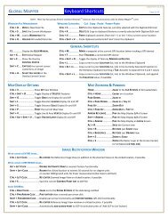
♦ Reference Guide - Shortcut Key Reference<br />
♦ Reference Guide - Supported Datum and Ellipsoid List<br />
♦ Reference Guide - Built-In Area, Line, and Point Types and Styles<br />
3. MENUBAR AND TOOLBAR<br />
a. File Menu<br />
• Open Data File(s) Command<br />
• Open Generic ASCII Text File(s) Command<br />
• Open All Files in a Directory Tree<br />
• Open ECW File from the Web Command<br />
• Open Data File at Fixed Screen Location<br />
• Unload All Command<br />
• Create New Map Catalog Command<br />
• Find Data Online Command<br />
• Download Online Imagery/Topo/Terrain Maps<br />
Open Printable/Searchable Copy (PDF Format) 1
<strong>Global</strong> <strong>Mapper</strong> - <strong>User's</strong> <strong>Manual</strong><br />
• Load Workspace Command<br />
• Save Workspace Command<br />
• Save Workspace As Command<br />
• Run Script Command<br />
• Capture Screen Contents to Image Command<br />
• Export <strong>Global</strong> <strong>Mapper</strong> Package File<br />
• Export Raster and Elevation Data<br />
• Export Vector Data<br />
• Export Web Formats (Google Maps, VE, WW, etc.)<br />
• Batch Convert/Reproject<br />
• Combine Terrain Layers<br />
• Generate Contours Command<br />
• Rectify (Georeference) Imagery Command<br />
• Print Command<br />
• Print Preview Command<br />
• Print Setup Command<br />
• Exit Command<br />
b. Edit Menu<br />
◊ Copy Selected Features to Clipboard<br />
◊ Cut Selected Features to Clipboard<br />
◊ Paste Features from Clipboard<br />
◊ Paste Features from Clipboard (Keep Copy)<br />
◊ Select All Features with Digitizer Tool<br />
c. View Menu<br />
◊ Toolbars<br />
◊ Status Bar<br />
◊ 3D View<br />
◊ Background Color<br />
◊ Center on Location<br />
◊ Properties<br />
◊ Full View<br />
◊ Zoom In<br />
◊ Zoom In Micro<br />
◊ Zoom Out<br />
◊ Zoom Out Micro<br />
◊ Zoom To Scale<br />
◊ Save Current View<br />
◊ Restore Last Saved View<br />
d. Tools Menu<br />
◊ Zoom<br />
◊ Pan (Grab-and-Drag)<br />
◊ Measure<br />
◊ Feature Info<br />
◊ Path Profile/LOS (Line of Sight)<br />
◊ View Shed Analysis<br />
◊ Digitizer/Edit<br />
⋅ Creating New Features<br />
⋅ Editing Existing Features<br />
⋅ Copying Features (Cut/Copy/Paste)<br />
⋅ Snapping to Existing Features When Drawing<br />
⋅ Snapping Vertically/Horizontally When Drawing<br />
Table of Contents 2
<strong>Global</strong> <strong>Mapper</strong> - <strong>User's</strong> <strong>Manual</strong><br />
⋅ Un-doing Digitization Operations<br />
⋅ Additional Feature Operations<br />
◊ Coordinate Convertor<br />
◊ Control Center<br />
◊ Configure<br />
e. Search Menu<br />
f. GPS Menu<br />
◊ Start Tracking GPS<br />
◊ Stop Tracking GPS<br />
◊ Keep the Vessel On-Screen<br />
◊ Mark Waypoint<br />
◊ Vessel Color<br />
◊ Vessel Size<br />
◊ Setup...<br />
◊ Information...<br />
◊ Manage GPS Vessels...<br />
◊ View NMEA Data Log...<br />
◊ Clear Tracklog<br />
◊ Record Tracklog<br />
◊ Save Tracklog<br />
g. Help Menu<br />
◊ Online Help<br />
◊ <strong>User's</strong> Group<br />
◊ Register <strong>Global</strong> <strong>Mapper</strong><br />
◊ Check for Updates<br />
◊ Automatically Check for Updates at Startup<br />
◊ About <strong>Global</strong> <strong>Mapper</strong><br />
4. OVERLAY CONTROL CENTER<br />
a. Currently Opened Overlays<br />
b. Metadata<br />
c. Options<br />
◊ Shapefile Data Options<br />
◊ Vector Data Options<br />
◊ Raster Data Options<br />
◊ Elevation Data Options<br />
d. Show/Hide Overlay(s)<br />
e. Close Overlay(s)<br />
5. LOADING FILES<br />
a. Loading Multiple Files<br />
b. Projections and Datums<br />
6. CHANGE DISPLAY CHARACTERISTICS<br />
a. General Options<br />
b. Vector Display Options<br />
c. Area Styles<br />
d. Line Styles<br />
e. Point Styles<br />
f. Vertical Options<br />
g. Shader Options<br />
h. Projection Options<br />
Table of Contents 3
ABOUT THIS MANUAL<br />
This manual is for <strong>Global</strong> <strong>Mapper</strong> v10.02. Earlier versions of the software may not contain all the features<br />
documented here. Later versions may contain additional features, or behave differently. To see the version of<br />
your software, select [Help/About <strong>Global</strong> <strong>Mapper</strong>] from the Menu Bar. The demo version contains some but<br />
not all of the features available through a registered version of <strong>Global</strong> <strong>Mapper</strong>.<br />
The <strong>Global</strong> <strong>Mapper</strong> Web Site found at: http://www.globalmapper.com maintains a list of changes and<br />
supported formats, features, links to sample data as well as current information about the <strong>Global</strong> <strong>Mapper</strong><br />
software. Please refer to this site to obtain the latest copy of the software.<br />
Earlier versions of the software should be uninstalled [Start/Settings/Control Panel/Add, Remove Programs]<br />
before installing later versions.<br />
System Requirements<br />
<strong>Global</strong> <strong>Mapper</strong> software is compatible with Windows 98, Windows NT, Windows 2000, Windows ME,<br />
Windows XP (32 and 64-bit versions), and Windows Vista (32 and 64-bit versions). You may also be able to<br />
run <strong>Global</strong> <strong>Mapper</strong> on a Macintosh computer using an emulator like VirtualPC, Parallels, or Boot Camp, or<br />
on a Linux OS under WINE. The minimum system requirements are 64 MB of RAM and 40 MB of hard drive<br />
space for the installation. Space requirements for the data are typically higher depending upon the size of the<br />
dataset.<br />
Download<br />
Step 1: Download the <strong>Global</strong> <strong>Mapper</strong> software (latest version) from the <strong>Global</strong> <strong>Mapper</strong> website:<br />
http://www.globalmapper.com by following the Download link on the left side of the main page.<br />
Step 2: Go to the directory in which you saved the viewer in Step 1 and select the global_mapper8_setup.exe<br />
icon<br />
Step 3: Double click the icon. Select "YES" to install the program. Allow the installation to progress normally<br />
and select any defaults it asked for.<br />
Registration<br />
<strong>Global</strong> <strong>Mapper</strong> - <strong>User's</strong> <strong>Manual</strong><br />
You can freely download the latest version of <strong>Global</strong> <strong>Mapper</strong> by following the instructions above. However,<br />
without a valid username and registration key, several significant functions will be unavailable. In particular,<br />
if you do not obtain a valid registration key for your copy of <strong>Global</strong> <strong>Mapper</strong> you will be subject to the<br />
following limitations:<br />
• You will be unable to export data to any format.<br />
• You will be limited to loading a maximum of 4 data files at a time. With the full version, you can load<br />
any number of data files simultaneously.<br />
• You will be unable to view loaded elevation data in 3D.<br />
• You will be unable to load workspaces.<br />
• You will be unable to do line of sight calculations using loaded elevation data.<br />
• You will be unable to perform view shed analysis using loaded elevation data.<br />
• You will be unable to perform cut-and-fill volume calculations using loaded elevation data.<br />
• You will be unable to work with map catalogs.<br />
• You will be unable to download data from WMS map servers.<br />
Table of Contents 4
<strong>Global</strong> <strong>Mapper</strong> - <strong>User's</strong> <strong>Manual</strong><br />
• You will be unable to save rectified imagery to fully rectified files.<br />
• You will not be able to print to a specific scale (i.e. 1:1000).<br />
• You will have to endure a nagging registration dialog everytime that you run the program.<br />
• You will not be eligible for free email support.<br />
CLICK HERE TO REGISTER your copy of <strong>Global</strong> <strong>Mapper</strong> and obtain access to all of its powerful features,<br />
Table of Contents 5
2 MENUBAR AND TOOLBAR<br />
This section briefly reviews the menus and commands in order to understand the basic purpose of each. Figure<br />
1 shows the program Toolbar as it appears at startup.<br />
Toolbar<br />
Figure 1 - Menu Bar and Toolbar<br />
The toolbar is displayed across the top of the application window, below the menu bar. The toolbar provides<br />
quick mouse access to many tools used in <strong>Global</strong> <strong>Mapper</strong>. To hide or display the Toolbar, choose Toolbar<br />
from the View menu.<br />
Menu Headings<br />
File Menu<br />
• File Menu<br />
• Edit Menu<br />
• View Menu<br />
• Tools Menu<br />
• Search Menu<br />
• GPS Menu<br />
• Help Menu<br />
The File menu offers the following commands:<br />
<strong>Global</strong> <strong>Mapper</strong> - <strong>User's</strong> <strong>Manual</strong><br />
• Open Data File(s) Command<br />
• Open Generic ASCII Text File(s) Command<br />
• Open All Files in a Directory Tree Command<br />
• Open ECW File from the Web Command<br />
• Open Data File at Fixed Screen Location<br />
• Unload All Command<br />
• Create New Map Catalog Command<br />
• Find Data Online Command<br />
• Download Online Imagery/Topo/Terrain Maps<br />
• Load Workspace Command<br />
• Save Workspace Command<br />
Table of Contents 6
<strong>Global</strong> <strong>Mapper</strong> - <strong>User's</strong> <strong>Manual</strong><br />
• Save Workspace As Command<br />
• Run Script Command<br />
• Capture Screen Contents to Image Command<br />
• Export <strong>Global</strong> <strong>Mapper</strong> Package File Command<br />
• Export Raster and Elevation Data<br />
♦ Export Arc ASCII Grid Command<br />
♦ Export BIL/BIP/BSQ Command<br />
♦ Export BT (Binary Terrain) Command<br />
♦ Export DEM Command<br />
♦ Export DTED Command<br />
♦ Export DXF 3D Face File Command<br />
♦ Export DXF Mesh Command<br />
♦ Export DXF Point File Command<br />
♦ Export ECW Command<br />
♦ Export Erdas Imagine Command<br />
♦ Export Float/Grid Command<br />
♦ Export Geosoft Grid Command<br />
♦ Export GeoTIFF Command<br />
♦ Export <strong>Global</strong> <strong>Mapper</strong> Grid Command<br />
♦ Export Gravsoft Grid Command<br />
♦ Export HF2/HFZ Command<br />
♦ Export Idrisi Command<br />
♦ Export JPG Command<br />
♦ Export JPG2000 Command<br />
♦ Export KML/KMZ Command<br />
♦ Export Lidar LAS Command<br />
♦ Export Leveller Heightfield Command<br />
♦ Export NITF Command<br />
♦ Export Optimi Terrain Command<br />
♦ Export PGM Grayscale Grid Command<br />
♦ Export PLS-CADD XYZ File Command<br />
♦ Export PNG Command<br />
♦ Export RockWorks Grid Command<br />
♦ Export STL Command<br />
♦ Export Surfer Grid (ASCII Format) Command<br />
♦ Export Surfer Grid (Binary v6 Format) Command<br />
♦ Export Surfer Grid (Binary v7 Format) Command<br />
♦ Export Terragen Terrain File Command<br />
♦ Export Vulcan3D Triangulation File Command<br />
♦ Export XYZ Grid Command<br />
♦ Export ZMap Plus Grid File Command<br />
• Export Vector Data<br />
♦ Export Arc Ungenerate Command<br />
♦ Export CDF Command<br />
♦ Export CSV Command<br />
♦ Export Delft 3D (LDB) Command<br />
♦ Export DeLorme Text File Command<br />
♦ Export DGN Command<br />
♦ Export DLG-O Command<br />
♦ Export DXF Command<br />
♦ Export Garmin TRK (PCX5) File Command<br />
Table of Contents 7
♦ Export Garmin WPT (PCX5) File Command<br />
♦ Export GOG (Generalized Overlay Graphics) Command<br />
♦ Export GPX Command<br />
♦ Export InRoads ASCII Command<br />
♦ Export KML/KMZ Command<br />
♦ Export Landmark Graphics Command<br />
♦ Export Lidar LAS Command<br />
♦ Export Lowrance USR Command<br />
♦ Export MapGen Command<br />
♦ Export MapInfo MIF/MID Command<br />
♦ Export MapInfo TAB/MAP Command<br />
♦ Export MatLab Command<br />
♦ Export Moss Command<br />
♦ Export NIMA ASC Command<br />
♦ Export Platte River File Command<br />
♦ Export PLS-CADD XYZ File Command<br />
♦ Export Polish MP (cGPS<strong>Mapper</strong>) File Command<br />
♦ Export SEGP1 Command<br />
♦ Export Shapefile Command<br />
♦ Export Simple ASCII Text File Command<br />
♦ Export Surfer BLN Command<br />
♦ Export SVG Command<br />
♦ Export Tom Tom OV2 File Command<br />
♦ Export Tsunami OVR Command<br />
♦ Export WAsP MAP File Command<br />
♦ Export ZMap+ XYSegId File Command<br />
• Export Web Formats (Google Maps, VE, WW, etc.)<br />
♦ Export Google Maps Tiles Command<br />
♦ Export KML/KMZ Command<br />
♦ Export SVG Command<br />
♦ Export VRML Command<br />
♦ Export Virtual Earth Tiles Command<br />
♦ Export World Wind Tiles Command<br />
• Batch Convert/Reproject<br />
• Combine Terrain Layers<br />
• Generate Contours Command<br />
• Print Command<br />
• Print Preview Command<br />
• Print Setup Command<br />
• Exit Command<br />
Open Data File(s) Command<br />
<strong>Global</strong> <strong>Mapper</strong> - <strong>User's</strong> <strong>Manual</strong><br />
The Open Data File(s) command allows the user to open additional data files into the main <strong>Global</strong> <strong>Mapper</strong><br />
view. If no other data is already loaded and the user has not explicitly set a projection, the view will adopt the<br />
projection and datum of the first data file selected for loading. If other data is already loaded, the selected data<br />
files will be displayed in the current projection/datum.<br />
Note: <strong>Global</strong> <strong>Mapper</strong> automatically opens files with tar.gz extensions without the use of a decompression tool<br />
such as Winzip. This is particularly useful for SDTS transfers, which are typically distributed in a .tar.gz<br />
Table of Contents 8
format.<br />
Open Generic ASCII Text File(s) Command<br />
<strong>Global</strong> <strong>Mapper</strong> - <strong>User's</strong> <strong>Manual</strong><br />
The Open Generic ASCII Text File(s) command allows the user to import data from a wide variety of generic<br />
ASCII text formats.<br />
Selecting the Open Generic ASCII Text File command prompts the user to select the file(s) to load and then<br />
displays the Generic ASCII Text Import Options dialog (pictured below). This dialog allows the user to<br />
specify how the text file(s) are formatted so that they can be imported.<br />
<strong>Global</strong> <strong>Mapper</strong> supports coordinates in decimal format as well as degree/minute and degree/minute/second<br />
coordinates.<br />
The Import Type section allows the user to specify how they want the data in the file to be treated. The<br />
different import types are defined as follows:<br />
• Point Only - All lines from the file which are determined to contain coordinate data will result in a<br />
single point feature to be generated.<br />
• Point, Line, and Area Features - Any string of two or more consecutive lines with coordinate data<br />
will result in a line or area feature. All isolated coordinate lines will result in a point feature.<br />
• Elevation Grid - All lines from the file which are determined to contain 3D coordinate data will be<br />
use generated a triangulated terrain which is then gridded to create a elevation grid. This grid has all<br />
the capabilities of an imported DEM, including contour generation, line of sight and view shed<br />
analysis, and raster draping. When selecting this option, the Create Elevation Grid dialog will appear<br />
after setting up the ASCII file import options to allow setting up the gridding process.<br />
The Coordinate Column Order section allows the user to specify in what order the coordinates are found on<br />
Table of Contents 9
<strong>Global</strong> <strong>Mapper</strong> - <strong>User's</strong> <strong>Manual</strong><br />
coordinate lines in the file. Coordinates can either be x followed by y (i.e. longitude then latitude) or the<br />
reverse. Elevation values, if any, are always assumed to come after the x and y values. The Columns to Skip at<br />
Start of Line setting controls what column the coordinates start in. For example, if the x and y coordinates are<br />
in the 3rd and 4th columns, set this value to 2 so that the coordinates will be grabbed from the appropriate<br />
place.<br />
The Coordinate Delimeter section allows the user to specify what character the coordinates are separated by<br />
on coordinate lines. If the Auto-Detect option is selected, <strong>Global</strong> <strong>Mapper</strong> will attempt to automatically<br />
determine the coordinate delimeter. This option will usually work and should probably be used unless you<br />
have trouble.<br />
The Coordinate Line Prefix section allows the user to specify whether coordinates start at the beginning of the<br />
line or if coordinate lines start with some other sequence of characters. For example, some formats may start<br />
coordinate lines with the sequence "XY,".<br />
The Feature Classification section allows the user to specify what feature type to assign to area, line, and<br />
point features imported from the file.<br />
If the Include attributes from lines with coordinate data option is selected, any text found AFTER the<br />
coordinate data on a line from the file will be including as attribute for the feature that coordinate is in. If not<br />
selected, only lines from the file that are not determined to contain coordinate data will be used as attributes.<br />
If you are doing a Point Only import and the Column Headers in First Row of File option is checked, values<br />
in the first line from the file will be used at the names of attributes for attributes found in coordinate data lines.<br />
This is useful for things like CSV files.<br />
If the Treat 3rd coordinate value as elevation option is selected and a numeric value is found immediately<br />
following the x and y (or lat and lon) coordinate values, that value will be treated as an elevation. Otherwise,<br />
the value will be included as an attribute if the Include attributes from lines with coordinate data option is<br />
selected. Typically you want to leave this option checked unless you are importing point data in which the 3rd<br />
column is an attribute that occasionally contains all numeric values, such as well names.<br />
If you have line and/or area data that do not have non-coordinate lines separating them but rather are delimited<br />
by a change in a particular field/column of data, you can use the Break Line/Area Features on Change in<br />
Field option to specify which field (use a 1-based index) to check for breaking the data into separate line/area<br />
features.<br />
Pressing the Select Coordinate Offset/Scale button displays a dialog that allows the user to select an offset and<br />
scale factor to apply to each coordinate. The offset entered will first be added to each coordinate, and then<br />
each coordinate will be multiplied by the scale factor.<br />
When generic ASCII text files are imported, <strong>Global</strong> <strong>Mapper</strong> will scan the attributes associated with each<br />
feature and look for any attribute names that are known to it. The following is an abbreviated list of attribute<br />
names that are currently recognized by <strong>Global</strong> <strong>Mapper</strong> when generic ASCII text files are read (see the links<br />
below the list for more complete lists):<br />
• NAME or LABEL - the value associated with an attribute of either of these names will be used as the<br />
feature name.<br />
• DESC, DESCRIPTION, LAYER, or TYPE - the value associated with an attribute of any of these<br />
names will be used as the feature description.<br />
Table of Contents 10
<strong>Global</strong> <strong>Mapper</strong> - <strong>User's</strong> <strong>Manual</strong><br />
• GM_TYPE - the value associated with an attribute with this name or any of the description names<br />
listed above will be used to attempt to assign a classification other than the default for each feature.<br />
The value must match one of the classification names in <strong>Global</strong> <strong>Mapper</strong> to work. It will also work for<br />
user-created custom types.<br />
• ELEVATION, HEIGHT, or DEPTH - the value associated with an attribute of any of these names<br />
will be used as the feature's elevation.<br />
• SYMBOL, POINT SYMBOL, or POINT_SYMBOL - the values associated with an attribute of any<br />
of these names will be compared against the names of the symbols available in <strong>Global</strong> <strong>Mapper</strong><br />
(including any custom symbols). If a match is found, that symbol will be used for the point feature.<br />
These attribute names are ignored for line features. You can also specify custom dot and square<br />
symbol colors and sizes without having to add your own custom bitmaps for those symbols. Use<br />
names of the form DOT_CUSTOM_[SIZE]_[RED]_[GREEN]_[BLUE] and<br />
SQUARE_CUSTOM_[SIZE]_[RED]_[GREEN]_[BLUE] where the [SIZE] value is the radius in<br />
pixels of the dot or square, and the [RED], [GREEN], and [BLUE] values represent the color to use.<br />
For example, to specify a dot symbol of radius 10 pixels with a color or green, you would use a<br />
symbol name of DOT_CUSTOM_10_0_255_0.<br />
• COLOR - the COLOR attribute should be formatted as RGB(red,green,blue). In the absence of a<br />
specific fill or line color, it will be used.<br />
• LINE COLOR, LINE_COLOR, BORDER COLOR, BORDER_COLOR, PEN COLOR, or<br />
PEN_COLOR - the values associated with an attribute of any of these names will be used as the color<br />
for the pen used to draw line features. The values must be formatted according to the guidelines layed<br />
out for the COLOR attribute in order to be recognized.<br />
• LINE WIDTH, LINE_WIDTH, BORDER WIDTH, BORDER_WIDTH, PEN WIDTH, or<br />
PEN_WIDTH - the values associated with an attribute of any of these names will be used as the width<br />
for the pen used to draw line features.<br />
• LINE STYLE, LINE_STYLE, BORDER STYLE, BORDER_STYLE, PEN STYLE, or PEN_STYLE<br />
- the values associated with an attribute of any of these names will be used as the style for the pen<br />
used to draw line features. Valid values are Solid, Dash, Dot, Dash - Dot, Dash - Dot - Dot, and Null.<br />
Only the Solid value is valid for lines with a width greater than 1<br />
• LABEL_ON_LINE - if this is set to "YES" or "TRUE", the label (if any) for this line feature should<br />
be rendered centered on the line<br />
• CLOSED - if this is set to "YES" or "TRUE", the feature will be treated as a closed area feature if it<br />
has at least three vertices.<br />
• ISLAND - if this is set to "YES" or "TRUE", the feature will be treated as an island of the previous<br />
closed parent area feature if it has at least three vertices. If there are no previous parent areas, this<br />
attribute will be ignored.<br />
• FONT_NAME - specifies the name (e.g. Arial, Times New Roman, etc.) of the font to use when<br />
displaying the display label, if any, for this feature.<br />
• FONT_COLOR - specifies the color of the font to use when displaying the display label, if any, for<br />
this feature. The values must be formatted according to the guidelines layed out for the COLOR<br />
attribute in order to be recognized.<br />
• FONT_ANGLE - specifies the angle in degrees of the font to use when displaying the display label, if<br />
any, for this point feature.<br />
• FONT_SIZE - specifies the point size of the font to use when displaying the display label, if any, for<br />
this feature.<br />
• FONT_HEIGHT_METERS - specifies the height in meters of the font to use when displaying the<br />
display label, if any, for this feature. Using this causes the actual point size of the font to vary as you<br />
zoom in and out.<br />
• FONT_CHARSET - specifies the numeric character set of the font to use when displaying the display<br />
label, if any, for this feature. These correspond to the Windows character set enumeration.<br />
Table of Contents 11
Click here for more instructions on creating generic ASCII data files with features of various types and click<br />
here for more documentation on the supported fields.<br />
Download Online Imagery/Topo/Terrain Maps<br />
<strong>Global</strong> <strong>Mapper</strong> - <strong>User's</strong> <strong>Manual</strong><br />
The Download Online Imagery/Topo/Terrain Maps command allows the user to download mapping data from<br />
numerous built-in and user-supplied sources. This includes premium access to high resolution color imagery<br />
for the entire world from Digital Globe, GlobeXplorer, and AirPhotoUSA, as well as seamless USGS<br />
topographic maps and satellite imagery for the entire United States, as well as high resolution color aerial<br />
imagery for select metropolitan areas from TerraServer-USA. In addition, access is provided to several<br />
built-in WMS (OpenGC Web Map Server) databases to provide easy access to digitial terrain data and color<br />
satellite imagery for the entire world. You can also add your own WMS data sources for access to any data<br />
published on a WMS server.<br />
This is an extremely powerful feature as it puts many terabytes of usually very expensive data right at your<br />
fingertips in <strong>Global</strong> <strong>Mapper</strong> for no additional cost (with the exception of access to the un-watermarked Digital<br />
Globe imagery, which is not free). Note that this feature requires Internet access to work.<br />
When you select the menu command, the Select Online Data Source to Download dialog (pictured below) is<br />
displayed. This dialog allows you to select the type, or theme, of data to download, as well as the extents of<br />
the data to download. You can either select to download the current screen bounds, an area to download<br />
around an address, specify a lat/lon bounds explicitly, or select to download the entire data source.<br />
Table of Contents 12
Once the data to download is defined, <strong>Global</strong> <strong>Mapper</strong> will automatically download the most appropriate layer<br />
for display as you zoom in and out. This way, you can see an overview of the data when zoomed out, with<br />
more detail becoming available when you zoom in. You can also export this data in full resolution to any of<br />
the supported raster export formats, such as GeoTIFF, JPG, or ECW. The most appropriate detail level for the<br />
export sample spacing will be used to obtain the source data for the export.<br />
Each data source load will appear as a separate layer in the Overlay Control Center. Each entry can have it's<br />
display options modified just like any other raster layer to drape it over elevation data, blend it with other<br />
layers, etc.<br />
You can use the Add WMS Data Source button to display the Select WMS Data Source to Load dialog<br />
(pictured below). This dialog allows you to specify the URL of a WMS data source and select what layer(s) to<br />
add as an available data source on the Select Online Data Source to Download dialog. The URL that you<br />
should specify is the GetCapabilities URL, such as http://wms.jpl.nasa.gov/wms.cgi for the JPL WMS data<br />
server (a great source of data, like Blue Marble imagery). Once you've entered the URL, press the Get List of<br />
Available Data Layers button to query the server and populate the data control with the available data layers<br />
on that server. Then simply select the data layer and style that you want and press OK to have it added to the<br />
available data source list. Once a source is added, you can use the Remove Source button to remove it from<br />
the list of available data sources at a later time. If you need to specify additional options for the WMS server,<br />
such as forcing a particular image format to be used, add those parameters after the Service Name parameter.<br />
For example, to force the use of the JPG format, you might specify a Service Name parameter of<br />
'WMS&format=image/jpeg'.<br />
Open All Files in a Directory Tree Command<br />
<strong>Global</strong> <strong>Mapper</strong> - <strong>User's</strong> <strong>Manual</strong><br />
The Open All Files in a Directory Tree command allows the user to open all of the files matching a<br />
user-specified filename mask under a user-selected directory. You will first be prompted to select a folder<br />
from which to load the files. After selecting the folder, you will be prompted to enter a filename mask for all<br />
Table of Contents 13
of the files that you would like to attempt to load. After selecting a filename mask, all files under the selected<br />
folder which match the filename mask and are recognized by <strong>Global</strong> <strong>Mapper</strong> as a known data type will be<br />
loaded.<br />
The filename mask supports the * and ? wildcard characters. The default mask of * will check all files under<br />
the selected folder. You can also cause data to only be loaded from selected folders as well. For example, if<br />
you had a large collection of folders with data split up into 1x1 degree blocks with the folder names depecting<br />
the 1x1 degree block they held, you could use a directory name mask to load only those blocks that you<br />
wanted. For example, you might use a mask of N4?W10?\*.tif to load all TIFF files between N40 and N50<br />
and W110 and W100.<br />
You can also specify multiple masks if you need more than one to describe the set of files that you would like<br />
to load. Simply separate the masks with a space.<br />
Open ECW File from the Web Command<br />
<strong>Global</strong> <strong>Mapper</strong> - <strong>User's</strong> <strong>Manual</strong><br />
The Open ECW File from the Web command allows the user to open an ER <strong>Mapper</strong> Compressed Wavelet<br />
(ECW) image file directly from an Image Web Server URL. While these files may be terabytes in actual size,<br />
only the portion needed for the current display window is downloaded, allowing for the browsing of<br />
extremely large data sets.<br />
Selecting the Open ECW File from the Web command displays the Load Image From Web dialog (pictured<br />
below). This dialog allows the user to either select a predefined web link for loading or to enter the URL of<br />
any available ECW file served by Image Web Server.<br />
The tree on the left of the dialog allows the user to select which data file they wish to load. <strong>Global</strong> <strong>Mapper</strong><br />
comes with several dozen useful links already entered into the tree.<br />
To access your own ECW image from the web, press the Add Link... button. This button causes the Add New<br />
Web Link dialog (pictured below) to be displayed.<br />
Table of Contents 14
The Group Name drop list allows the user to select which group, if any, to place the new link in. Any of the<br />
predefined groups can be selected, or a new group name can be entered. Leaving the group name blank will<br />
cause the new link to appear at the root level of the tree.<br />
The Description field is where you enter the human-readable description of the link. This is what will be<br />
displayed for the link on the main dialog. Leaving this blank will cause the URL to be displayed instead.<br />
The URL field is the most important piece of this dialog. This is where you specify the address of the ECW<br />
file to load. The URL should begin with the prefix ecwp:// with the remainder being a valid path to an ECW<br />
file served using ER <strong>Mapper</strong>'s Image Web Server software.<br />
When you've completed entering information about the new web link, press the OK button to complete your<br />
entry and have it added to the web link tree in the Load Image From Web dialog.<br />
Pressing the Edit Link... button allows the user to edit the currently selected web link. Note that the built-in<br />
web links cannot be edited.<br />
Pressing the Delete Link... button will delete the currently selected web link or group from the web link tree.<br />
If you get an error message indicating that your settings have been updated to support the ECWP protocol<br />
whenever you try to load an ECW layer from the web you need to download and install the latest ECW<br />
ActiveX plugin from http://demo.ermapper.com/ecwplugins/DownloadIEPlugin.htm.<br />
Open Data File at Fixed Screen Location<br />
<strong>Global</strong> <strong>Mapper</strong> - <strong>User's</strong> <strong>Manual</strong><br />
The Open Data File at Fixed Screen Location command allows the user to open any supported data file format<br />
for display at a fixed location on the screen rather than at a fixed location on the earth. This is particularly<br />
useful for loading things like bitmaps for legends and logos. The loaded data will be used for screen display,<br />
export, and printing operations.<br />
Selecting the Open Data File at Fixed Screen Location command first prompts you to select a file to load, then<br />
displays the Fixed Screen Location Setup dialog (pictured below). This dialog allows the user to specify the<br />
size and position of the data relative to the screen/export/printout.<br />
Table of Contents 15
Unload All Command<br />
The Unload All command unloads all overlays and clears the screen.<br />
Create New Map Catalog Command<br />
<strong>Global</strong> <strong>Mapper</strong> - <strong>User's</strong> <strong>Manual</strong><br />
The Create New Map Catalog command allows you to create a "map catalog". A "map catalog" is a collection<br />
of map files which are grouped together to allow for easy loading, viewing, and export. Layers in a map<br />
catalog will be loaded and unloaded as needed for display and export, potentially greatly reducing the load<br />
time and memory requirements for working with very large collections of data.<br />
Upon selecting this command and selecting the file to save the map catalog to, the Modify Map Catalog dialog<br />
(shown below) will be displayed, allowing you to add files to the catalog and control at what zoom level data<br />
layers are loaded for display.<br />
Table of Contents 16
You can obtain metadata and projection information about layers in the map catalog by right-clicking on them<br />
in the Map List and selecting the appropriate option.<br />
You can modify map catalogs again after loading them by opening the Overlay Control Center, selecting the<br />
map catalog layer, then pressing the Options button.<br />
Note: Only registered users of <strong>Global</strong> <strong>Mapper</strong> are able to create map catalogs.<br />
Load Workspace Command<br />
The Load Workspace command allows the user to load a <strong>Global</strong> <strong>Mapper</strong> workspace file (.gsw) previously<br />
saved with the Save Workspace command.<br />
Note: Only registered users of <strong>Global</strong> <strong>Mapper</strong> are able to load <strong>Global</strong> <strong>Mapper</strong> workspace files.<br />
Save Workspace Command<br />
<strong>Global</strong> <strong>Mapper</strong> - <strong>User's</strong> <strong>Manual</strong><br />
The Save Workspace command allows the user to save their current set of loaded overlays to a <strong>Global</strong> <strong>Mapper</strong><br />
workspace file for later loading with the Load Workspace command.<br />
The <strong>Global</strong> <strong>Mapper</strong> workspace maintains the list of all currently loaded overlays as well as some state<br />
information about each of those overlays. When the workspace file is loaded, all of the overlays that were<br />
loaded at the time the workspace file was saved will be loaded into <strong>Global</strong> <strong>Mapper</strong>. This provides a handy<br />
way to easily load a group of overlays which you work with often.<br />
The <strong>Global</strong> <strong>Mapper</strong> workspace will also contain any changes that you have made to loaded vector features as<br />
well as any new vector features that you have created. The user projection and last view on the data will also<br />
be maintained.<br />
Table of Contents 17
Find Data Online Command<br />
Selecting the Find Data Online command will open a web browser pointing to places on the internet where<br />
data compatible with <strong>Global</strong> <strong>Mapper</strong> is available for download.<br />
Run Script Command<br />
The Run Script command allows users to run a <strong>Global</strong> <strong>Mapper</strong> script file that they have created. This is a<br />
powerful option that allows the user to automate a wide variety of tasks. Click here for a guide to the scripting<br />
language.<br />
Selecting the Run Script command from the menu displays the Script Processing dialog, shown here.<br />
The Script File pane displays the currently loaded script file. To load a new script file for processing, press the<br />
Load Script... button at the bottom left corner of the dialog.<br />
If you would like the script file to make use of data already loaded in the main view and to also affect what is<br />
displayed in the main view, check the Run Script in the Context of the Main View option prior to running the<br />
script.<br />
To run the loaded script file, press the Run Script button. Any warning, error, or status messages generated<br />
while running the script will be output to the Script Results pane.<br />
When you are done processing scripts, press the Cancel button to close the dialog.<br />
Note: Only registered users of <strong>Global</strong> <strong>Mapper</strong> are able to run <strong>Global</strong> <strong>Mapper</strong> script files.<br />
Capture Screen Contents to Image Command<br />
<strong>Global</strong> <strong>Mapper</strong> - <strong>User's</strong> <strong>Manual</strong><br />
Table of Contents 18
<strong>Global</strong> <strong>Mapper</strong> - <strong>User's</strong> <strong>Manual</strong><br />
The Capture Screen Contents to Image command allows user to save the current contents of the <strong>Global</strong><br />
<strong>Mapper</strong> window to a JPEG, PNG, (Geo)TIFF, or Windows Bitmap (BMP) file. In addition, the generated<br />
image can be generated in a higher resolution than the screen to provide greater fidelity. Also, a world file for<br />
georeferencing in other software packages as well as a projection (PRJ) file describing the native ground<br />
reference system of the image can be optionally generated as well.<br />
Unlike the raster export commands described later, the Capture Screen Contents to Image command also<br />
saves any vector overlays drawn to the screen.<br />
Selecting the Capture Screen Contents to Image command from the menu displays the Screen Capture<br />
Options dialog, shown here.<br />
The Image Format section allows the user to select the format of the image to generate. Different formats<br />
have their own unique strenghts and weaknesses which make choosing the best format vary depending on the<br />
desired end results. The supported formats are:<br />
• JPEG - JPEG is a lossy format that achieves excellent compression on images with a lot of color<br />
variation, such as pictures of real world objects and shaded elevation data.<br />
• PNG (Portable Network Graphic) - PNG is a lossless format that achieves excellent compression on<br />
images without a lot of color variation, such as line (vector) drawings and paper map scans such as<br />
DRGs. The generated PNG file will be of the 24-bit variety.<br />
• (Geo)TIFF - TIFF is a lossless format that is supported by many GIS packages. Saving the screen to a<br />
TIFF with this command generated a 24-bit uncompressed TIFF. In addition, all georeferencing data<br />
is stored in a GeoTIFF header attached to the TIFF, making the image completely self-describing.<br />
• Windows Bitmap (BMP) - BMP is a widely support format on Windows platforms. Saving the screen<br />
to a BMP results in a 24-bit uncompressed image.<br />
The width and height of the generated image in pixels are specified in the Image Size panel. By default, the<br />
size of the <strong>Global</strong> <strong>Mapper</strong> view pane are used. Using these values will generate an image that exactly matches<br />
Table of Contents 19
what you see. You can change these values to generate a more or less resolute image with the obvious tradeoff<br />
of size vs. quality.<br />
Checking the Generate World File option results in a world file being generated in addition to the image. The<br />
world file will be generated in the same directory as the image and will have the same primary name as the<br />
image. The filename extension will depend on the selected image type (JPEG=.jpgw, PNG=.pngw,<br />
TIFF=.tfw,BMP=.bmpw).<br />
Checking the Generate Projection (PRJ) File option results in a projection file being generated describing the<br />
ground reference system of the created image. The projection file will be generated in the same directory as<br />
the image and will have the same primary name as the image with an extension of .prj.<br />
Checking the Generate Text Metadata File option results in a text file being generated listing the metadata for<br />
the captured image.<br />
Pressing the OK button prompts the user to select the name and location of the image to generate and then<br />
proceeds to generate the image.<br />
Note: Only registered users of <strong>Global</strong> <strong>Mapper</strong> are able capture the screen to an image file.<br />
Export <strong>Global</strong> <strong>Mapper</strong> Package File Command<br />
<strong>Global</strong> <strong>Mapper</strong> - <strong>User's</strong> <strong>Manual</strong><br />
The Export <strong>Global</strong> <strong>Mapper</strong> Package File command allows the user to export any or all of the loaded data to a<br />
<strong>Global</strong> <strong>Mapper</strong> package file. These files are similar to workspace files except that the actual data is stored in<br />
the files. Package files provide an easy way to pass around lots of data between <strong>Global</strong> <strong>Mapper</strong> users on<br />
different computers with a single self-contained file.<br />
When selected, the command displays the <strong>Global</strong> <strong>Mapper</strong> Package Export Options dialog which allows the<br />
user to setup the package export. The dialog consists of a Package Options panel, a Simplification panel, a<br />
Gridding panel, and an Export Bounds panel.<br />
Table of Contents 20
<strong>Global</strong> <strong>Mapper</strong> - <strong>User's</strong> <strong>Manual</strong><br />
The Package Options panel consists of options allowing the user to select the projection to save the data in,<br />
how to handle dynamically streamed TerraServer data, and other options. These include the Always Maintain<br />
Feature Styles option, which specifies that any vector features stored in the package file should explicitly save<br />
the styling of that feature, even if they are using the default style for the feature classification. This can make<br />
it easier to maintain exact styling when transferring packages between <strong>Global</strong> <strong>Mapper</strong> installations.<br />
In the Projection section of the panel, the user can choose to save all loaded data in the currently selected<br />
view projection (this is the projection selected on the Projection tab of the Configuration dialog), in<br />
latitude/longitude coordinates (the "Geographic" projection) with the WGS84 datum, or to keep each layer in<br />
its original native projection.<br />
In the TerraServer Export Options section of the panel, the user can select how displayed layers from the<br />
Download TerraServer menu option are exported. The Automatic selection for imagery themes (i.e. DOQs,<br />
Urban Area imagery) will save data slightly more detailed than what is displayed on the screen. For the DRG<br />
(topographic map) theme, the most detailed zoom range for the current scale of DRG map being displayed<br />
(i.e. 24K, 100K, 250K) will be determined and data from that scale will be saved. The other alternatives either<br />
save the most detailed scale available, creating potentially very large files, or the scale the most closely<br />
Table of Contents 21
matches the current display scale on the screen.<br />
The Simplification panel allows the user to set up the threshold at which points that don't contribute much to<br />
the shape of the vector line and area features being exported are removed in order to generate features with<br />
less vertices. By default, all vertices will be kept, but the user can move the slider to the right to get rid of<br />
relatively insignificant vertices and realize significant space spacings at the cost of some fidelity.<br />
The Gridding panel allows the user to split up the data into regularly spaced tiles on export if desired rather<br />
than just exporting a single file.<br />
The Export Bounds panel allows the user to select what portion of the loaded data they wish to export.<br />
Note: Only registered users of <strong>Global</strong> <strong>Mapper</strong> are able capture the screen to an image file.<br />
Export Raster and Elevation Data<br />
The commands on the Export Raster and Elevation Data submenu allow the user to export loaded raster and<br />
elevation data to various formats.<br />
Export Arc ASCII Grid Command<br />
The Export Arc ASCII Grid command allows the user to export any loaded elevation grid data sets to an Arc<br />
ASCII Grid format file.<br />
When selected, the command displays the Arc ASCII Grid Export Options dialog which allows the user to<br />
setup the export. The dialog consists of a General options panel which allows the user to set up the grid<br />
spacing and vertical units, a Gridding panel and an Export Bounds panel which allows the user to set up the<br />
portion of the loaded data they wish to export.<br />
Note: Only registered users of <strong>Global</strong> <strong>Mapper</strong> are able to export data to any format.<br />
Export BIL/BIP/BSQ Command<br />
<strong>Global</strong> <strong>Mapper</strong> - <strong>User's</strong> <strong>Manual</strong><br />
The Export BIL/BIP/BSQ command allows the user to export any loaded raster, vector, and/or elevation grid<br />
data to a BIL, BIP, or BSQ format file.<br />
When selected, the command displays the BIL/BIP/BSQ Export Options dialog which allows the user to setup<br />
the export. The dialog consists of an Options panel (pictured below), which allows the user to set up type of<br />
export to perform, the sample spacing, vertical units, and other applicable options, a Gridding Panel, and an<br />
Export Bounds panel which allows the user to set up the portion of the loaded data they wish to export.<br />
Table of Contents 22
Note: Only registered users of <strong>Global</strong> <strong>Mapper</strong> are able to export data to any format.<br />
Export BT (Binary Terrain) Command<br />
The Export BT (Binary Terrain) command allows the user to export any loaded elevation grid data sets to a<br />
BT (Binary Terrain) format file.<br />
When selected, the command displays the BT (Binary Terrain) Export Options dialog which allows the user to<br />
setup the export. The dialog consists of a General options panel which allows the user to set up the grid<br />
spacing to use, a Gridding panel, and an Export Bounds panel which allows the user to set up the portion of<br />
the loaded data they wish to export.<br />
Note: Only registered users of <strong>Global</strong> <strong>Mapper</strong> are able to export data to any format.<br />
Export DEM Command<br />
<strong>Global</strong> <strong>Mapper</strong> - <strong>User's</strong> <strong>Manual</strong><br />
The Export DEM command allows the user to export any loaded elevation grid data sets to a native format<br />
USGS DEM file.<br />
Table of Contents 23
When selected, the command displays the DEM Export Options dialog which allows the user to setup the<br />
export. The dialog consists of a General options panel which allows the user to set up the quadrangle name,<br />
grid spacing and vertical units, a Gridding panel, and an Export Bounds panel which allows the user to set up<br />
the portion of the loaded data they wish to export.<br />
Note: Only registered users of <strong>Global</strong> <strong>Mapper</strong> are able to export data to any format.<br />
Export DTED Command<br />
The Export DTED command allows the user to export any loaded elevation grid data sets to native format<br />
DTED files. DTED files support a set of fixed resolutions (i.e. DTED levels) which are defined as aligning on<br />
particular boundaries. When you select the DTED level to export to and the export bounds, this defines which<br />
DTED tiles need to be generated to conform to the DTED standards for that level. The filename that you<br />
select for the export is used as a base, with the lat/lon coordinates of the southwest corner of each tile<br />
appended to each filename as it is exported.<br />
When selected, the command displays the DTED Export Options dialog which allows the user to setup the<br />
export. The dialog consists of a DTED Options panel which allows the user to set up the DTED level and<br />
other options, a Gridding panel, and an Export Bounds panel which allows the user to set up the portion of the<br />
loaded data they wish to export.<br />
Note: Only registered users of <strong>Global</strong> <strong>Mapper</strong> are able to export data to any format.<br />
Export DXF 3D Face File Command<br />
The Export DXF 3D Face File command allows the user to export any loaded gridded elevation data sets to a<br />
DXF 3D Face file.<br />
When selected, the command displays the DXF 3D Face Export Options dialog which allows the user to setup<br />
the export. The dialog consists of a General options panel which allows the user to set up the grid spacing and<br />
vertical units, a Gridding panel, and an Export Bounds panel which allows the user to set up the portion of the<br />
loaded data they wish to export.<br />
Note: Only registered users of <strong>Global</strong> <strong>Mapper</strong> are able to export data to any format.<br />
Export DXF Mesh Command<br />
The Export DXF Mesh command allows the user to export any loaded elevation grid data sets to a 3D DXF<br />
Mesh file.<br />
When selected, the command displays the DXF Mesh Export Options dialog which allows the user to setup<br />
the export. The dialog consists of a General options panel which allows the user to set up the grid spacing and<br />
vertical units, a Gridding panel, and an Export Bounds panel which allows the user to set up the portion of the<br />
loaded data they wish to export.<br />
Note: Only registered users of <strong>Global</strong> <strong>Mapper</strong> are able to export data to any format.<br />
Export DXF Point Command<br />
<strong>Global</strong> <strong>Mapper</strong> - <strong>User's</strong> <strong>Manual</strong><br />
The Export DXF Point command allows the user to export any loaded elevation grid data sets to a 3D DXF<br />
Point file. The DXF file will consist of a 3D DXF point for each point in the elevation grid defined by the<br />
Table of Contents 24
spacing and extents that the user specifies. This option may be useful when used with other software packages<br />
that do not specify the DXF mesh format.<br />
When selected, the command displays the 3D DXF Point Export Options dialog which allows the user to<br />
setup the export. The dialog consists of a General options panel which allows the user to set up the grid<br />
spacing and vertical units, a Gridding panel, and an Export Bounds panel which allows the user to set up the<br />
portion of the loaded data they wish to export.<br />
Note: Only registered users of <strong>Global</strong> <strong>Mapper</strong> are able to export data to any format.<br />
Export ECW Command<br />
The Export ECW command allows the user to export any loaded raster, vector, and elevation grid data sets to<br />
an ECW file. ECW files are highly compressed and great for storing things like satellite imagery. There is no<br />
size restriction on exported ECW files, so you can store many terabytes worth of imagery within a single<br />
highly compressed ECW file.<br />
When selected, the command displays the ECW Export Options dialog which allows the user to setup the<br />
export. The dialog consists of a General options panel which allows the user to set up the pixel spacing and<br />
target compression ration, a Gridding panel, and an Export Bounds panel which allows the user to set up the<br />
portion of the loaded data they wish to export. If you would like to generate a lossless JPG2000 format file,<br />
simply slide the Target Compression Ratio slider all the way to the right (1:1 target compression ration).<br />
Note: Only registered users of <strong>Global</strong> <strong>Mapper</strong> are able to export data to any format.<br />
Export Erdas Imagine Command<br />
The Export Erdas Imagine command allows the user to export any loaded raster, vector,and elevation grid<br />
data sets to an Erdas Imagine file.<br />
When selected, the command displays the Erdas Imagine Export Options dialog which allows the user to<br />
setup the export. The dialog consists of a General options panel which allows the user to set up the pixel<br />
spacing and format, a Gridding panel, and an Export Bounds panel which allows the user to set up the portion<br />
of the loaded data they wish to export.<br />
Note: Only registered users of <strong>Global</strong> <strong>Mapper</strong> are able to export data to any format.<br />
Export Float/Grid Command<br />
<strong>Global</strong> <strong>Mapper</strong> - <strong>User's</strong> <strong>Manual</strong><br />
The Export Float/Grid command allows the user to export any loaded elevation grid data sets to a Float/Grid<br />
format file. The Float/Grid file will consist of a 4-byte IEEE floating point number for each elevation sample<br />
in the file, starting at the top-left corner and proceeding across, then down. In addition to the elevation data<br />
file, an ESRI-format .hdr file and .prj file will also be generated. There is also an option to allow exporting<br />
slope values (in degrees) or slope directions (in bearings where 0 is north, 90 is east, etc.) rather than elevation<br />
values at each sample location.<br />
When selected, the command displays the Float/Grid Point Export Options dialog which allows the user to<br />
setup the export. The dialog consists of a General options panel which allows the user to set up the grid<br />
spacing and vertical units, a Gridding panel, and an Export Bounds panel which allows the user to set up the<br />
portion of the loaded data they wish to export.<br />
Table of Contents 25
Note: Only registered users of <strong>Global</strong> <strong>Mapper</strong> are able to export data to any format.<br />
Export Geosoft Grid Command<br />
The Export Geosoft Grid command allows the user to export any loaded elevation grid data sets to a Geosoft<br />
Binary Grid format file.<br />
When selected, the command displays the Geosoft Grid Export Options dialog which allows the user to setup<br />
the export. The dialog consists of a General options panel which allows the user to set up the grid spacing to<br />
use, a Gridding panel, and an Export Bounds panel which allows the user to set up the portion of the loaded<br />
data they wish to export.<br />
Note: Only registered users of <strong>Global</strong> <strong>Mapper</strong> are able to export data to any format.<br />
Export GeoTIFF Command<br />
<strong>Global</strong> <strong>Mapper</strong> - <strong>User's</strong> <strong>Manual</strong><br />
The Export GeoTIFF command allows the user to export any loaded raster, vector, and elevation data sets to a<br />
GeoTIFF format file.<br />
When selected, the command displays the GeoTIFF Export Options dialog (pictured below) which allows the<br />
user to set up the export. The dialog consists of a GeoTIFF Options panel, a Gridding panel, and an Export<br />
Bounds panel which allows the user to set up the portion of the loaded vector data they wish to export.<br />
Table of Contents 26
<strong>Global</strong> <strong>Mapper</strong> - <strong>User's</strong> <strong>Manual</strong><br />
The File Type section allows you to choose what type of GeoTIFF file to generate. The various file types are<br />
described below:<br />
• 8-bit Palette Image - This option generates a 256-color raster GeoTIFF file with 8-bits per pixel. The<br />
Palette options described below will apply in this case. This option will generate a relatively small<br />
output file, at the expense of some color fidelity depending on the palette that you choose. The image<br />
data will be compressed using the PackBits compression algorithm.<br />
• 24-bit RGB - This option generates a raster GeoTIFF file with 24-bits per pixel. GeoTIFF images<br />
generated with this option will be at least 3 times the size of those generated with the 8-bit Palette<br />
option, but the colors in the image will exactly match what you see on the screen.<br />
• JPEG-in-TIFF - This option generates a raster GeoTIFF file with 24-bits per pixel but with the raster<br />
data compressed using the JPG compression algorithm. GeoTIFF images generated with this option<br />
will maintain good color fidelity and often be highly compressed, although they will lose some<br />
information as compared to the uncompressed 24-bit RGB option. Something else to keep in mind if<br />
selecting this option is that many software packages do not yet support GeoTIFF files that use the<br />
JPEG-in-TIFF compression option. By default the JPG compression used in the GeoTIFF file uses a<br />
Table of Contents 27
<strong>Global</strong> <strong>Mapper</strong> - <strong>User's</strong> <strong>Manual</strong><br />
quality setting of 75, but you can modify this by creating a new DWORD registry key with the<br />
desired value at "HKEY_CURRENT_USER\Software\<strong>Global</strong> <strong>Mapper</strong>\JpegInTiffQuality".<br />
• Black and White- This option generates a two color GeoTIFF file with 1 bit per pixel. This will<br />
generate by far the smallest image, but if you source image had more than two colors the resulting<br />
image will be very poor. By default, white will be a value of 0 and black will be a value of 1, but you<br />
can reverse this by selecint the Grayscale - Min Is Black palette option.<br />
• Elevation (16-bit integer samples) - This option generates an elevation GeoTIFF using the currently<br />
loaded elevation grid data sets. Elevation samples will be stored as signed 16-bit integers. There are<br />
only a handful of software packages that can recognize a vertical GeoTIFF properly, so only use this<br />
if you know it works.<br />
• Elevation (32-bit floating pointr samples) - This option generates an elevation GeoTIFF using the<br />
currently loaded elevation grid data sets. Elevation samples will be stored as 32-bit floating point<br />
values. There are only a handful of software packages that can recognize a vertical GeoTIFF properly,<br />
so only use this if you know it works.<br />
When generating a 256 color (8-bits per pixel) GeoTIFF, it is necessary to select a palette indicates what 256<br />
colors will be used to describe the image being exported. The following choices of palette are available:<br />
• Image Optimized Palette - The palette generated will be an optimal mix of up to 256 colors that will<br />
closely represent the full blend of colors in the source images. This option will generate the best<br />
results, but can more than double the export time required if any high color images are present in the<br />
export set. If all of the input data is palette-based and the combined palette of those files has 256<br />
colors or less, then the combined files of the input file will just be used with no additional export time<br />
being required.<br />
• Grayscale Palette - This palette consists of 256 scales of gray ranging from black to white.<br />
• DRG Optimized Palette - This palette is optimized for the exporting USGS DRG data. The palette<br />
consists of only the standard DRG colors.<br />
• DRG/DOQ Optimized Palette - As the name suggests, this palette is optimized for exporting a mixture<br />
of USGS DRG data and grayscale satellite photos (i.e. USGS DOQs). The palette consists of the 14<br />
standard DRG colors with the remaining 242 colors being a range of gray values ranging from black<br />
to white.<br />
• Halftone Palette - The palette consists of a blend of 256 colors evenly covering the color spectrum.<br />
This palette is the best choice when exporting anything but DRGs and grayscale satellite photos.<br />
• Custom Palette from File - This option allows the user to choose a .pal file describing the palette to<br />
use for the export. A .pal file should be a text file with one line per color, with the red, green, and blue<br />
color components for each color in the palette separated by a comma. You can save a .pal file for an<br />
existing palette-based file by opening the Overlay Control Center, selecting the palette-based layer,<br />
press Options, then the Transparent Color button, then selecting the option to save a color palette file.<br />
• Grayscale - Min is Black Palette - This palette creates an 8-bit per pixel grayscale image with no<br />
color map stored in the image. Black will be stored as zero with varying shades of gray up to white<br />
with a value of 255.<br />
• Grayscale - Min is White Palette - This palette creates an 8-bit per pixel grayscale image with no<br />
color map stored in the image. White will be stored as zero with varying shades of gray up to black<br />
with a value of 255.<br />
The Vertical Units field allows the user to select the vertical units to use when exporting elevation data (i.e.<br />
meters or feet). Any input data not in the selected vertical units will be automatically converted on export.<br />
The Resolution section allows the user to selected the grid spacing to use when generating the GeoTIFF. The<br />
default value is the average of the grid spacings of all the currently loaded raster and elevation overlays. If the<br />
Always Generate Square Pixels option is checked, the smaller of the specified x and y resolutions will be used<br />
Table of Contents 28
for both the x and y resolution. Forcing square pixels ensures that the resultant GeoTIFF file will look good<br />
even in software that is not able to deal with pixels that aren't square. If you'd like to specify the spacing in<br />
units other than those of the currently selected view/export projection, press the Click Here to Calculate<br />
Spacing in Other Units button.<br />
The DPI Value to Save in Image option allows you to specify a DPI (dots per inch) value to save in the TIFF<br />
header. Some software, in particular graphics editing software, makes use of this value when sizing TIFF files<br />
for printout. Specifying the default value of 0 will result in the DPI tag not being saved to the TIFF file at all.<br />
If the Save Scale/Elevation Legend/Grid if Displayed option is checked, the distance scale, elevation legend,<br />
and coordinate grid will be saved to the GeoTIFF file (except vertical GeoTIFFs) if they are configured to<br />
show up in the main display.<br />
If the Save Vector Data if Displayed option is checked, any loaded vector data that is configured to show up in<br />
the main display will be saved to the GeoTIFF file (except vertical GeoTIFFs).<br />
If the Generate TFW File option is checked a TIFF world file will be generated with the same name as the<br />
GeoTIFF file with a .tfw extension. The TFW file is used by software that is not capable of reading the<br />
placement of the GeoTIFF file directly from the GeoTIFF header.<br />
If the Interpolate to Fill Small Gaps in Data option is checked, any small areas with missing data will be<br />
filled in by interpolating the surrounding valid data. This is useful for filling small gaps between adjacent tiles<br />
or small holes in elevation data.<br />
If the Use LZW Compression option is checked, the image data will be compressed using the LZW<br />
compression algorithm. This generally results in the best compression for TIFF files, but is not yet supported<br />
by all software applications. If the application(s) that you are going to be using the TIFF file with supports<br />
LZW, using this compression method is definitely suggested.<br />
If the Generate PRJ File option is checked a describing the projection of the coordinates in the file will<br />
automatically be created<br />
If the Make Background (Void) Pixels Transparent option is checked for 24-bit RGB or JPEG-in-TIFF files,<br />
an alpha channel will be added to the created GeoTIFF file to indicate which pixels should be treated as<br />
transparent. Note that this will create a larger file and not all applications will support TIFF files with alpha<br />
channels.<br />
Export <strong>Global</strong> <strong>Mapper</strong> Grid Command<br />
<strong>Global</strong> <strong>Mapper</strong> - <strong>User's</strong> <strong>Manual</strong><br />
The Export <strong>Global</strong> <strong>Mapper</strong> Grid command allows the user to export any loaded elevation grid data sets to a<br />
<strong>Global</strong> <strong>Mapper</strong> Grid format file. The <strong>Global</strong> <strong>Mapper</strong> Grid format is a highly compressed elevation grid format<br />
that loads and draws very quickly and requires very little memory. If you have a choice for what format to<br />
store your gridded elevation data in, we suggest using the <strong>Global</strong> <strong>Mapper</strong> Grid format.<br />
When selected, the command displays the <strong>Global</strong> <strong>Mapper</strong> Grid Export Options dialog which allows the user<br />
to setup the export. The dialog consists of a General options panel which allows the user to set up the grid<br />
spacing and vertical units, a Gridding panel, and an Export Bounds panel which allows the user to set up the<br />
portion of the loaded data they wish to export.<br />
Note: Only registered users of <strong>Global</strong> <strong>Mapper</strong> are able to export data to any format.<br />
Table of Contents 29
Export Google Maps Tiles Command<br />
<strong>Global</strong> <strong>Mapper</strong> - <strong>User's</strong> <strong>Manual</strong><br />
The Export Google Maps Tiles command allows the user to export any loaded datato JPG or PNG files tiled<br />
in the configuration required for display in using the Google Maps interface. This command will create both<br />
the image tiles and a sample HTML file for displaying the data with the Google Maps interface. You can just<br />
load the HTML file into your web browser to view the data once the export is over. You can also customize<br />
the HTML file however you need to.<br />
When you select the command, the Google Maps Export Options dialog (pictured below) appears allowing<br />
you to setup the export. This dialog allows you to specify the display name of the map set in your web<br />
browser, the zoom level setup, the Google Maps API key to use, the format of the imagery, and some<br />
additional options. There is also an Export Bounds panel which allows the user to set up the portion of the<br />
loaded data they wish to export.<br />
Note: Users without a permanent registration key that export Google Maps tiles will get a large diagonal<br />
Table of Contents 30
DEMO symbol across the image. Registered users will not see that symbol on their output.<br />
Export Gravsoft Grid Command<br />
The Export Gravsoft Grid command allows the user to export any loaded elevation grid data sets to a Gravsoft<br />
Grid format file.<br />
When selected, the command displays the Gravsoft Grid Export Options dialog which allows the user to setup<br />
the export. The dialog consists of a General options panel which allows the user to set up the grid spacing and<br />
vertical units, a Gridding panel, and an Export Bounds panel which allows the user to set up the portion of the<br />
loaded data they wish to export.<br />
Note: Only registered users of <strong>Global</strong> <strong>Mapper</strong> are able to export data to any format.<br />
Export HF2/HFZ Command<br />
The Export HF2/HFZ command allows the user to export any loaded raster, vector,and elevation grid data sets<br />
to an HF2/HFZ format file.<br />
When selected, the command displays the HF2/HFZ Export Options dialog which allows the user to setup the<br />
export. The dialog consists of a General options panel which allows the user to set up the pixel spacing and<br />
format, a Gridding panel, and an Export Bounds panel which allows the user to set up the portion of the<br />
loaded data they wish to export.<br />
Note: Only registered users of <strong>Global</strong> <strong>Mapper</strong> are able to export data to any format.<br />
Export Idrisi Command<br />
The Export Idrisi command allows the user to export any loaded raster, vector,and elevation grid data sets to<br />
an Idrisi file.<br />
When selected, the command displays the Idrisi Export Options dialog which allows the user to setup the<br />
export. The dialog consists of a General options panel which allows the user to set up the pixel spacing and<br />
format, a Gridding panel, and an Export Bounds panel which allows the user to set up the portion of the<br />
loaded data they wish to export.<br />
Note: Only registered users of <strong>Global</strong> <strong>Mapper</strong> are able to export data to any format.<br />
Export JPG Command<br />
The Export JPG command allows the user to export any loaded raster, vector, and elevation grid data sets to a<br />
JPG file.<br />
When selected, the command displays the JPG Export Options dialog which allows the user to setup the<br />
export. The dialog consists of a General options panel which allows the user to set up the pixel spacing, a<br />
Gridding panel, and an Export Bounds panel which allows the user to set up the portion of the loaded data<br />
they wish to export.<br />
Note: Only registered users of <strong>Global</strong> <strong>Mapper</strong> are able to export data to any format.<br />
Export JPG2000 Command<br />
<strong>Global</strong> <strong>Mapper</strong> - <strong>User's</strong> <strong>Manual</strong><br />
Table of Contents 31
The Export JPG2000 command allows the user to export any loaded raster, vector, and elevation grid data sets<br />
to a JPG2000 format file. JPG2000 files are highly compressed and great for storing things like satellite<br />
imagery. There is no size restriction on exported JPG2000 files, so you can store many terabytes worth of<br />
imagery within a single highly compressed JPG2000 file.<br />
When selected, the command displays the JPG2000 Export Options dialog which allows the user to setup the<br />
export. The dialog consists of a General options panel which allows the user to set up the pixel spacing and<br />
target compression ration, a Gridding panel, and an Export Bounds panel which allows the user to set up the<br />
portion of the loaded data they wish to export. If you would like to generate a lossless JPG2000 format file,<br />
simply slide the Target Compression Ratio slider all the way to the right (1:1 target compression ration).<br />
Note: Only registered users of <strong>Global</strong> <strong>Mapper</strong> are able to export data to any format.<br />
Export KML/KMZ Command<br />
<strong>Global</strong> <strong>Mapper</strong> - <strong>User's</strong> <strong>Manual</strong><br />
The Export KML/KMZ command allows the user to export any loaded raster, vector, and elevation grid data<br />
sets to a KML/KMZ format file for display in Google Earth. If you are wanting to export a vector KML/KMZ<br />
file from loaded vector data, use the File->Export Vector Data->Export KML/KMZ menu command instead.<br />
When selected, the command displays the KML/KMZ Export Options dialog (pictured below) which allows<br />
the user to setup the export. The dialog consists of a KML/KMZ Options panel, a Gridding panel, and an<br />
Export Bounds panel which allows the user to set up the portion of the loaded data they wish to export.<br />
The KML/KMZ Options panel allows the user to set up the target image format for storage and the sample<br />
spacing, as well as other options such as whether to store all of the resulting files in a KMZ file<br />
(recommended) and whether or not to render and save loaded vector data. There is also an option to<br />
automatically grid the data on export (this creates what is known as a SuperOverlay). Enabling this option<br />
allows very large quantities of data to be efficiently viewed using Google Earth. When using this option you<br />
can also control the tile size to use when creating the super overlays. For very large exports the larger sizes<br />
(1024x1024 or 2048x2048) are recommended.<br />
Table of Contents 32
Note: Only registered users of <strong>Global</strong> <strong>Mapper</strong> are able to export data to any format.<br />
Export Leveller Heightfield Command<br />
The Export Leveller Heightfield command allows the user to export any loaded elevation grid data sets to a<br />
Leveller Heightfield file for use with the Daylon Leveller application.<br />
When selected, the command displays the Leveller Heightfield Export Options dialog which allows the user to<br />
setup the export. The dialog consists of a General options panel which allows the user to set up the grid<br />
spacing and vertical units, a Gridding panel, and an Export Bounds panel which allows the user to set up the<br />
portion of the loaded data they wish to export.<br />
Note: Only registered users of <strong>Global</strong> <strong>Mapper</strong> are able to export data to any format.<br />
Export Lidar LAS Command<br />
<strong>Global</strong> <strong>Mapper</strong> - <strong>User's</strong> <strong>Manual</strong><br />
Table of Contents 33
The Export Lidar LAS command allows the user to export any loaded elevation grid data sets to Lidar LAS<br />
format files.<br />
When selected, the command displays the Lidar LAS Export Options dialog which allows the user to setup the<br />
export. The dialog consists of a General options panel which allows the user to set up the grid spacing and<br />
vertical units, a Gridding panel, and an Export Bounds panel which allows the user to set up the portion of the<br />
loaded data they wish to export.<br />
Note: Only registered users of <strong>Global</strong> <strong>Mapper</strong> are able to export data to any format.<br />
Export NITF Command<br />
The Export NITF command allows the user to export any loaded raster, vector, and elevation grid data sets to<br />
a NITF (National Imagery Transmission Format) file.<br />
When selected, the command displays the NITF Export Options dialog which allows the user to setup the<br />
export. The dialog consists of a General options panel which allows the user to set up the pixel spacing, a<br />
Gridding panel, and an Export Bounds panel which allows the user to set up the portion of the loaded data<br />
they wish to export.<br />
Note: Only registered users of <strong>Global</strong> <strong>Mapper</strong> are able to export data to any format.<br />
Export Optimi Terrain File Command<br />
The Export Optimi Terrain File command allows the user to export any loaded elevation grid data sets to an<br />
Optimi Terrain format grid file. These terrain files can be used with applications from Optimi.<br />
When selected, the command displays the Optimi Terrain Export Options dialog which allows the user to<br />
setup the export. The dialog consists of a General options panel which allows the user to set up the grid<br />
spacing and vertical units, a Gridding panel, and an Export Bounds panel which allows the user to set up the<br />
portion of the loaded data they wish to export.<br />
Note: Only registered users of <strong>Global</strong> <strong>Mapper</strong> are able to export data to any format.<br />
Export PGM File Command<br />
The Export PGM File command allows the user to export any loaded elevation grid data sets to a PGM<br />
grayscale grid file. These grid files can be used with any software application that supports PGM files.<br />
When selected, the command displays the PGM Export Options dialog which allows the user to setup the<br />
export. The dialog consists of a General options panel which allows the user to set up the grid spacing and<br />
vertical units, a Gridding panel, and an Export Bounds panel which allows the user to set up the portion of the<br />
loaded data they wish to export.<br />
Note: Only registered users of <strong>Global</strong> <strong>Mapper</strong> are able to export data to any format.<br />
Export PLS-CADD XYZ File Command<br />
<strong>Global</strong> <strong>Mapper</strong> - <strong>User's</strong> <strong>Manual</strong><br />
The Export PLS-CADD XYZ File command allows the user to export any loaded elevation grid data sets to a<br />
PLS-CADD XYZ format grid file. These grid files can be used with the PLS-CADD software application.<br />
Table of Contents 34
When selected, the command displays the PLS-CADD XYZ Export Options dialog which allows the user to<br />
setup the export. The dialog consists of a General options panel which allows the user to set up the grid<br />
spacing and vertical units, a Gridding panel, and an Export Bounds panel which allows the user to set up the<br />
portion of the loaded data they wish to export.<br />
Note: Only registered users of <strong>Global</strong> <strong>Mapper</strong> are able to export data to any format.<br />
Export PNG Command<br />
The Export PNG command allows the user to export any loaded data sets to a PNG file.<br />
When selected, the command displays the PNG Export Options dialog which allows the user to setup the<br />
export. The dialog consists of an Options panel (pictured below), which allows the user to select whether to<br />
export an 8-bit palette-based PNG or a 24-bit RGB PNG file, as well as other applicable options, a Gridding<br />
panel, and an Export Bounds panel which allows the user to set up the portion of the loaded data they wish to<br />
export.<br />
Note: Only registered users of <strong>Global</strong> <strong>Mapper</strong> are able to export data to any format.<br />
Export RockWorks Grid Command<br />
<strong>Global</strong> <strong>Mapper</strong> - <strong>User's</strong> <strong>Manual</strong><br />
Table of Contents 35
The Export RockWorks Grid command allows the user to export any loaded elevation grid data sets to a<br />
RockWorks Grid format file.<br />
When selected, the command displays the RockWorks Grid Export Options dialog which allows the user to<br />
setup the export. The dialog consists of a General options panel which allows the user to set up the grid<br />
spacing and vertical units, a Gridding panel, and an Export Bounds panel which allows the user to set up the<br />
portion of the loaded data they wish to export.<br />
Note: Only registered users of <strong>Global</strong> <strong>Mapper</strong> are able to export data to any format.<br />
Export STL Command<br />
The Export STL command allows the user to export any loaded elevation grid data sets to a STL format file<br />
for use with some CAD systems.<br />
When selected, the command displays the STL Export Options dialog which allows the user to setup the<br />
export. The dialog consists of a General options panel which allows the user to set up the grid spacing and<br />
vertical units, a Gridding panel, and an Export Bounds panel which allows the user to set up the portion of the<br />
loaded data they wish to export.<br />
Note: Only registered users of <strong>Global</strong> <strong>Mapper</strong> are able to export data to any format.<br />
Export Surfer Grid (ASCII Format) Command<br />
The Export Surfer Grid (ASCII Format) command allows the user to export any loaded elevation grid data<br />
sets to an ASCII format Surfer Grid file.<br />
When selected, the command displays the Surfer Grid Export Options dialog which allows the user to setup<br />
the export. The dialog consists of a General options panel which allows the user to set up the grid spacing and<br />
vertical units, a Gridding panel, and an Export Bounds panel which allows the user to set up the portion of the<br />
loaded data they wish to export.<br />
Note: Only registered users of <strong>Global</strong> <strong>Mapper</strong> are able to export data to any format.<br />
Export Surfer Grid (Binary v6 Format) Command<br />
The Export Surfer Grid (Binary v6 Format) command allows the user to export any loaded elevation grid data<br />
sets to a binary format Surfer Grid file compatible with Surfer v6 and above. Binary format Surfer Grids will<br />
be smaller than their ASCII-format cousins, so if you can use the binary format I would suggest it.<br />
When selected, the command displays the Surfer Grid Export Options dialog which allows the user to setup<br />
the export. The dialog consists of a General options panel which allows the user to set up the grid spacing and<br />
vertical units, a Gridding panel, and an Export Bounds panel which allows the user to set up the portion of the<br />
loaded data they wish to export.<br />
Note: Only registered users of <strong>Global</strong> <strong>Mapper</strong> are able to export data to any format.<br />
Export Surfer Grid (Binary v7 Format) Command<br />
<strong>Global</strong> <strong>Mapper</strong> - <strong>User's</strong> <strong>Manual</strong><br />
The Export Surfer Grid (Binary v7 Format) command allows the user to export any loaded elevation grid data<br />
sets to a binary format Surfer Grid file compatible with Surfer v7 and above. Binary format Surfer Grids will<br />
Table of Contents 36
e smaller than their ASCII-format cousins, so if you can use the binary format I would suggest it.<br />
When selected, the command displays the Surfer Grid Export Options dialog which allows the user to setup<br />
the export. The dialog consists of a General options panel which allows the user to set up the grid spacing and<br />
vertical units, a Gridding panel, and an Export Bounds panel which allows the user to set up the portion of the<br />
loaded data they wish to export.<br />
Note: Only registered users of <strong>Global</strong> <strong>Mapper</strong> are able to export data to any format.<br />
Export Terragen Terrain File Command<br />
The Export Terragen Terrain File command allows the user to export any loaded elevation grid data sets to a<br />
Terragen terrain file.<br />
When selected, the command displays the Terragen Export Options dialog which allows the user to setup the<br />
export. The dialog consists of a General options panel which allows the user to set up the grid spacing and an<br />
Export Bounds panel which allows the user to set up the portion of the loaded data they wish to export.<br />
Note: Only registered users of <strong>Global</strong> <strong>Mapper</strong> are able to export data to any format.<br />
Export Vulcan3D Triangulation File Command<br />
The Export Vulcan3D Triangulation File command allows the user to export any loaded elevation grid data<br />
sets to a Vulcan3D triangulation file.<br />
When selected, the command displays the Vulcan3D Export Options dialog which allows the user to setup the<br />
export. The dialog consists of a General options panel which allows the user to set up the grid spacing and<br />
vertical units, a Gridding panel, and an Export Bounds panel which allows the user to set up the portion of the<br />
loaded data they wish to export.<br />
Note: Only registered users of <strong>Global</strong> <strong>Mapper</strong> are able to export data to any format.<br />
Export VRML Command<br />
The Export VRML command allows the user to export any loaded elevation grid data and raster data sets to a<br />
VRML file for display in a VRML viewer, such as the Cortona VRML Client.<br />
When selected, the command displays the VRML World File Export Options dialog which allows the user to<br />
setup the export. The dialog consists of a General options panel which allows the user to set up the grid<br />
spacing, vertical exaggeration, and compression options, and an Export Bounds panel which allows the user to<br />
set up the portion of the loaded data they wish to export.<br />
Note: Only registered users of <strong>Global</strong> <strong>Mapper</strong> are able to export data to any format.<br />
Export Virtual Earth Tiles Command<br />
<strong>Global</strong> <strong>Mapper</strong> - <strong>User's</strong> <strong>Manual</strong><br />
The Export Virtual Earth Tiles command allows the user to export any loaded data to JPG or PNG files tiled<br />
in the configuration required for display in using the Microsoft Virtual Earth interface. This command will<br />
create both the image tiles and a sample HTML file for displaying the data with the Virtual Earth interface.<br />
You can just load the HTML file into your web browser to view the data once the export is over. You can also<br />
customize the HTML file however you need to.<br />
Table of Contents 37
When you select the command, the Virtual Earth Export Options dialog (pictured below) appears allowing<br />
you to setup the export. This dialog allows you to specify the display name of the map set in your web<br />
browser, the zoom level setup, the format of the imagery, and some additional options. There is also an Export<br />
Bounds panel which allows the user to set up the portion of the loaded data they wish to export.<br />
Note: Users without a permanent registration key that export Virtual Earth tiles will get a large diagonal<br />
DEMO symbol across the image. Registered users will not see that symbol on their output.<br />
Export World Wind Tiles Command<br />
<strong>Global</strong> <strong>Mapper</strong> - <strong>User's</strong> <strong>Manual</strong><br />
The Export World Wind Tiles command allows the user to export any loaded data to JPG or PNG files tiled in<br />
the configuration required by NASA's World Wind application. This command will create both the image tiles<br />
and the XML file required for World Wind to use the data. You should place the generated .xml file in the<br />
Config\Earth folder under your World Wind installation folder in order for it to be picked up by World Wind.<br />
When you select the command, the World Wind Export Options dialog (pictured below) appears allowing you<br />
to setup the export. This dialog allows you to specify the display name of the map set in World Wind, the base<br />
directory to which the directory tree of map tiles will be exported, the zoom level setup, the format of the<br />
imagery, and some additional options. There is also an Export Bounds panel which allows the user to set up<br />
the portion of the loaded data they wish to export.<br />
Table of Contents 38
Note: Users without a permanent registration key that export World Wind tiles will get a large diagonal<br />
DEMO symbol across the image. Registered users will not see that symbol on their output.<br />
Export XYZ Grid Command<br />
The Export XYZ Grid command allows the user to export any loaded elevation grid data sets to a<br />
comma-delimited ASCII XYZ file. Each grid point will be represented as follows (actual coordinate delimiter<br />
is configurable):<br />
x-coordinate,y-coordinate,z-coordinate<br />
When selected, the command displays the XYZ Grid Export Options dialog which allows the user to setup the<br />
export. The dialog consists of a General options panel which allows the user to set up the grid spacing and<br />
vertical units, a Gridding panel, and an Export Bounds panel which allows the user to set up the portion of the<br />
loaded data they wish to export.<br />
Note: Only registered users of <strong>Global</strong> <strong>Mapper</strong> are able to export data to any format.<br />
Export Zmap Plus Grid File Command<br />
<strong>Global</strong> <strong>Mapper</strong> - <strong>User's</strong> <strong>Manual</strong><br />
The Export Zmap Plus Grid File command allows the user to export any loaded elevation grid data sets to a<br />
Table of Contents 39
Zmap Plus Grid format file.<br />
When selected, the command displays the Zmap Plus Grid Export Options dialog which allows the user to<br />
setup the export. The dialog consists of a General options panel which allows the user to set up the grid<br />
spacing and vertical units and an Export Bounds panel which allows the user to set up the portion of the<br />
loaded data they wish to export.<br />
Note: Only registered users of <strong>Global</strong> <strong>Mapper</strong> are able to export data to any format.<br />
Export Vector Data<br />
The commands on the Export Vector Data submenu allow the user to export loaded vector data to various<br />
formats.<br />
Export Arc Ungenerate Command<br />
The Export Arc Ungenerate commands allows the user to export any loaded vector data sets to an Arc<br />
Ungenerate format file.<br />
When selected, the command displays the Arc Ungenerate Export Options dialog which consists of an Export<br />
Bounds panel that allows the user to set up the portion of the loaded vector data they wish to export.<br />
Note: Only registered users of <strong>Global</strong> <strong>Mapper</strong> are able to export data to any format.<br />
Export CDF Command<br />
<strong>Global</strong> <strong>Mapper</strong> - <strong>User's</strong> <strong>Manual</strong><br />
The Export CDF command allows the user to export any loaded vector data sets to a CDF (Common Data<br />
Format) file.<br />
When selected, the command displays the CDF Export Options dialog (pictured below) which allows the user<br />
to set up the export. The dialog consists of a CDF Options panel which allows the user to set up the attribute<br />
code to assign to features and the text size in the export file, and an Export Bounds panel which allows the<br />
user to set up the portion of the loaded vector data they wish to export.<br />
If the Use Default Attribute for All Features option is checked, the attribute selected in the Default Attribute<br />
Code panel will be used for all features. Otherwise, the selected attribute will only be used for those features<br />
whose <strong>Global</strong> <strong>Mapper</strong> classification could not be automatically mapped to one of the CDF attributes.<br />
Table of Contents 40
Note: Only registered users of <strong>Global</strong> <strong>Mapper</strong> are able to export data to any format.<br />
Export CSV Command<br />
The Export CSV command allows the user to export any loaded point data sets to a CSV (Comma Separated<br />
File) file.<br />
When selected, the command displays the CSV Export Options dialog which allows the user to set up the<br />
export. The dialog consists of an Options panel which allows the user to set up whether or not to include an<br />
elevation attribute for each point as well as whether to include the name of each column in the file as the first<br />
row in the file. There is also an Export Bounds panel which allows the user to set up the portion of the loaded<br />
point data they wish to export.<br />
Note: Only registered users of <strong>Global</strong> <strong>Mapper</strong> are able to export data to any format.<br />
Export Delft3D (LDB) Command<br />
<strong>Global</strong> <strong>Mapper</strong> - <strong>User's</strong> <strong>Manual</strong><br />
The Export Delft3D (LDB) command allows the user to export any loaded vector line data sets to a Delft3D<br />
(LDB) format file.<br />
When selected, the command displays the Delft3D Export Options dialog which consists of an Export Bounds<br />
Table of Contents 41
panel that allows the user to set up the portion of the loaded vector data they wish to export.<br />
Note: Only registered users of <strong>Global</strong> <strong>Mapper</strong> are able to export data to any format.<br />
Export DeLorme Text File Command<br />
The Export DeLorme Text File command allows the user to export any loaded vector features to one of 3 text<br />
formats that can be loaded into select DeLorme mapping products.<br />
When selected, the command displays the DeLorme Text Polygon Export Options dialog which consists of an<br />
Export Bounds panel that allows the user to set up the portion of the loaded vector data they wish to export.<br />
Note: Only registered users of <strong>Global</strong> <strong>Mapper</strong> are able to export data to any format.<br />
Export DGN Command<br />
<strong>Global</strong> <strong>Mapper</strong> - <strong>User's</strong> <strong>Manual</strong><br />
The Export DGN command allows the user to export any loaded vector data to a MicroStation DGN v8<br />
format file.<br />
When selected, the command displays the DGN Export Options dialog (pictured below) which allows the user<br />
to set up the export. The dialog consists of a DGN Options panel, a Gridding panel, and an Export Bounds<br />
panel which allows the user to set up the portion of the loaded vector data they wish to export.<br />
Table of Contents 42
The Text Size section allows the user to control how large display label text will be in the created file. The<br />
Unit Resolution value is used to specify the resolution unit saved in the DGN file. If the Generate PRJ File<br />
option is checked, a .prj projection file describing the projection of the coordinates in the file will<br />
automatically be created. If the Generate 3D DGN File if 3D Features Present option is checked, the entire<br />
DGN file will be marked as 3D and any features that have a elevation data associated with them will be stored<br />
as 3D features. If the Generate Tags for Feature Attributes option is checked, any attributes associated with<br />
exported features will be saved as tags in the resulting file. Note that this can significantly slow down your<br />
export in some cases. If the Set <strong>Global</strong> Origin to the Lower Left of Design Plane Rather than the Center of the<br />
Design Plane option is set, the global origin is set to the minimum valid negative values rather than at (0,0) as<br />
is standard. If the Replace Dark Line Colors with White option is set, any lines that are near black in color will<br />
be replaced with a white line automatically. This is useful for getting dark colored lines to show up when the<br />
exported DGN file is viewed in an application that uses a black background.<br />
Note: Only registered users of <strong>Global</strong> <strong>Mapper</strong> are able to export data to any format.<br />
Export DLG-O Command<br />
<strong>Global</strong> <strong>Mapper</strong> - <strong>User's</strong> <strong>Manual</strong><br />
The Export DLG-O command allows the user to export any loaded vector data sets to a native format USGS<br />
DLG-O (Digital Line Graph Optional format) file.<br />
Table of Contents 43
When selected, the command displays the DLG-O Export Options dialog (pictured below) which allows the<br />
user to set up the export. The dialog consists of a DLG-O Options panel which allows the user to set up the<br />
banner name, DCU (digital cartographic unit or quad name), and category name, a Gridding panel, and an<br />
Export Bounds panel which allows the user to set up the portion of the loaded vector data they wish to export.<br />
If possible, the fields on the DLG-O Options panel are automatically filled in with the best guesses available<br />
based on the currently loaded data. The user is free to change the values to fit their needs.<br />
Note: Only registered users of <strong>Global</strong> <strong>Mapper</strong> are able to export data to any format.<br />
Export DXF Command<br />
<strong>Global</strong> <strong>Mapper</strong> - <strong>User's</strong> <strong>Manual</strong><br />
The Export DXF command allows the user to export any loaded vector data sets to an AutoCAD DXF format<br />
file.<br />
When selected, the command displays the DXF Export Options dialog (pictured below) which allows the user<br />
to set up the export. The dialog consists of a DXF Options panel, a Gridding panel, and an Export Bounds<br />
panel which allows the user to set up the portion of the loaded vector data they wish to export.<br />
Table of Contents 44
<strong>Global</strong> <strong>Mapper</strong> - <strong>User's</strong> <strong>Manual</strong><br />
The Display Labels section allows you to control if you want feature display labels included in the DXF files<br />
and, if so, whether you want them represented as TEXT entities in their own layer (called<br />
FEATURE_LABEL) or as DXF attributes. The default is to have them included as attributes associated with<br />
each feature. As some software packages cannot handle attributes in DXF files, you may have to switch to a<br />
different option (with the associated loss of information) to get your exported DXF files to work with some<br />
software packages. If you would like line features to have rotated labels running along the line associated with<br />
them, you have to use the option to Include Display Labels as Separate Text Layer.<br />
The Layer Names section allows you to control how the layer names used in the exported DXF file are<br />
generated. You can choose to use the feature description, feature display label, or feature source filename as<br />
the layer name in the exported file. If you choose to use the display label as the layer name, any features that<br />
do not have a display label will use the feature description as the layer name in the exported file.<br />
If selected, the Generate Projection (PRJ) File option causes a projection file describing the ground reference<br />
system of the DXF file to be generated in addition to the DXF file itself. The PRJ file will have the same<br />
name as the DXF file with the .prj extension.<br />
If selected, the Create 3D Features Using Loaded Elevation Data option will cause any underlying elevation<br />
data (like DEMs) to be used to retrieve elevation values for 2D features being exported and generate new 3D<br />
Table of Contents 45
features in the exported DXF file. The units used by the elevation values are determined by the Elevation<br />
Display/Export Units setting on the Vertical Options tab of the Configuration dialog.<br />
If selected, the Generate ECEF Coordinates option will cause the exported DXF file to use Earth-Centered<br />
Earth-Fixed (ECEF) XYZ coordinate values rather than XY values in the current export projection.<br />
If selected, the Generate Zero-Width Lines option causes and line features created in the DXF file to be<br />
marked as having zero width. Use this option if you intend to use the resulting DXF file with a product such<br />
as MicroStation which has problems with lines of non-zero thickness.<br />
Note: Only registered users of <strong>Global</strong> <strong>Mapper</strong> are able to export data to any format.<br />
Export Garmin TRK (PCX5) File Command<br />
The Export Garmin TRK (PCX5) File command allows the user to export any loaded vector line data to a<br />
Garmin TRK (PCX5) format file. This file can be imported by a wide variety of GPS software, such as<br />
Garmin's MapSource®, to facilitate transferring track logs to a GPS unit.<br />
When selected, the command displays the Garmin TRK Format Export Options dialog which allows the user<br />
to set up the export. The dialog consists of an Export Bounds panel which allows the user to set up the portion<br />
of the loaded vector data they wish to export.<br />
Note: Only registered users of <strong>Global</strong> <strong>Mapper</strong> are able to export data to any format.<br />
Export Garmin WPT (PCX5) File Command<br />
The Export Garmin WPT (PCX5) File command allows the user to export any loaded named point data to a<br />
Garmin WPT (PCX5) format file. This file can be imported by a wide variety of GPS software, such as<br />
Garmin's MapSource®, to facilitate transferring waypoints to a GPS unit.<br />
When selected, the command displays the Garmin WPT Format Export Options dialog which allows the user<br />
to set up the export. The dialog consists of an Export Bounds panel which allows the user to set up the portion<br />
of the loaded vector data they wish to export.<br />
Note: Only registered users of <strong>Global</strong> <strong>Mapper</strong> are able to export data to any format.<br />
Export GOG (Generalized Overlay Graphics) Command<br />
The Export GOG (Generalized Overlay Graphics) command allows the user to export any loaded vector data<br />
sets to a GOG format file.<br />
When selected, the command displays the GOG Export Options dialog which allows the user to set up the<br />
export. The dialog consists of an Export Bounds panel which allows the user to set up the portion of the<br />
loaded vector data they wish to export.<br />
Note: Only registered users of <strong>Global</strong> <strong>Mapper</strong> are able to export data to any format.<br />
Export GPX (GPS eXchange Format) Command<br />
<strong>Global</strong> <strong>Mapper</strong> - <strong>User's</strong> <strong>Manual</strong><br />
The Export GPX (GPS eXchange Format) commands allows the user to export any loaded point and line data<br />
to a GPX (GPS eXchange Format) file.<br />
Table of Contents 46
When selected, the command displays the GPX Export Options dialog which consists of an Export Bounds<br />
panel that allows the user to set up the portion of the loaded vector data they wish to export. If you want to fill<br />
in the <cmt> field of a feature during a GPX export, simply add a COMMENT attribute to the feature<br />
with the desired comment.<br />
Note: Only registered users of <strong>Global</strong> <strong>Mapper</strong> are able to export data to any format.<br />
Export InRoads ASCII Command<br />
The Export InRoads ASCII command allows the user to export any loaded vector data sets to an InRoads<br />
ASCII format file.<br />
When selected, the command displays the InRoads ASCII Export Options dialog which allows the user to set<br />
up the export. The dialog consists of an Export Bounds panel which allows the user to set up the portion of the<br />
loaded vector data they wish to export.<br />
Note: Only registered users of <strong>Global</strong> <strong>Mapper</strong> are able to export data to any format.<br />
Export KML/KMZ Command<br />
<strong>Global</strong> <strong>Mapper</strong> - <strong>User's</strong> <strong>Manual</strong><br />
The Export KML/KMZ command allows the user to export any loaded vector data sets to a KML/KMZ<br />
format file for use with Google Earth.<br />
When selected, the command displays the KML/KMZ Export Options dialog (pictured below) which allows<br />
the user to set up the export. The dialog consists of a KML/KMZ Options panel, a Gridding panel, and an<br />
Export Bounds panel which allows the user to set up the portion of the loaded vector data they wish to export.<br />
Table of Contents 47
<strong>Global</strong> <strong>Mapper</strong> - <strong>User's</strong> <strong>Manual</strong><br />
The 3D Line Export and 3D Area Export sections allow the user to control whether or not area and line<br />
features with elevation values associated with them are drawn at the terrain surface or at the elevation values<br />
associated with the feature. You can specify whether the elevation values are relative to ground level or sea<br />
level if drawing the features above the terrain. If area features are drawn above the terrain, the Extrude Areas<br />
option allows you to control whether or not they will also be extruded, which means they will extend back to<br />
the terrain surface, making them look like solid 3D features. If this option is not checked, the areas will just be<br />
drawn in space as a surface and not a 3D closed object. If the Fake 2D Area Heights to Maintain Area Draw<br />
Order option is checked, exported 2D area features will be assigned fake elevation values in order to attempt<br />
to get them to layer properly when displayed in Google Earth. This is only necessary if you have overlapping<br />
areas that do not display in the correct order without this option checked.<br />
The Filled Area Translucency section allows the user to control the degree to which filled polygons are<br />
see-through in the created file. If the Create Compressed KMZ File option is checked, a compressed KMZ file<br />
will automatically be created. This will result in much smaller files and is highly recommended unless you<br />
plan on manually editing the export result yourself in a text editor. If the Include Attribute Values in Feature<br />
Description option is checked, any feature attributes will be included in the description for a feature. If the<br />
Hide Point Features by Default When Loading File option is checked, all of the point features exported to the<br />
file will be hidden by default in Google Earth so as not to clutter up the display with a bunch of point icons. If<br />
the Display Area and Line Labels option is checked, each exported line or area feature with a display label<br />
Table of Contents 48
will also be marked with a clickable placemark displaying the label for that area or line feature. This is the<br />
only way to get line or area features to display labels in Google Earth.<br />
Note: Only registered users of <strong>Global</strong> <strong>Mapper</strong> are able to export data to any format.<br />
Export Landmark Graphics Command<br />
The Export Landmark Graphics command allows the user to export any loaded vector data sets to a Landmark<br />
Graphics format file.<br />
When selected, the command displays the Landmark Graphics Export Options dialog which allows the user to<br />
set up the export. The dialog consists of an Export Bounds panel which allows the user to set up the portion of<br />
the loaded vector data they wish to export.<br />
Note: Only registered users of <strong>Global</strong> <strong>Mapper</strong> are able to export data to any format.<br />
Export Lidar LAS Command<br />
The Export Lidar LAS command allows the user to export any loaded 3D vector data sets (like 3D point<br />
clouds loaded from other LAS files) to new Lidar LAS format files.<br />
When selected, the command displays the Lidar LAS Export Options dialog which allows the user to setup the<br />
export. The dialog consists of a Gridding panel, and an Export Bounds panel which allows the user to set up<br />
the portion of the loaded data they wish to export.<br />
Note: Only registered users of <strong>Global</strong> <strong>Mapper</strong> are able to export data to any format.<br />
Export Lowrance USR Command<br />
The Export Lowrance USR command allows the user to export any loaded vector data sets to a Lowrance<br />
USR format file for use in Lowrance brand GPS devices.<br />
When selected, the command displays the Lowrance USR Export Options dialog which allows the user to set<br />
up the export. The dialog consists of a Gridding panel and an Export Bounds panel which allows the user to<br />
set up the portion of the loaded vector data they wish to export.<br />
Note: Only registered users of <strong>Global</strong> <strong>Mapper</strong> are able to export data to any format.<br />
Export MapGen Command<br />
The Export MapGen command allows the user to export any loaded vector data sets to a MapGen format file.<br />
When selected, the command displays the MapGen Export Options dialog which allows the user to set up the<br />
export. The dialog consists of an Export Bounds panel which allows the user to set up the portion of the<br />
loaded vector data they wish to export.<br />
Note: Only registered users of <strong>Global</strong> <strong>Mapper</strong> are able to export data to any format.<br />
Export MapInfo MIF/MID Command<br />
<strong>Global</strong> <strong>Mapper</strong> - <strong>User's</strong> <strong>Manual</strong><br />
Table of Contents 49
The Export MapInfo MIF/MID command allows the user to export any loaded vector data sets to a MapInfo<br />
MIF/MID format file.<br />
When selected, the command displays the MapInfo Export Options dialog which allows the user to set up the<br />
export. The dialog consists of a Gridding panel and an Export Bounds panel which allows the user to set up<br />
the portion of the loaded vector data they wish to export.<br />
Note: Only registered users of <strong>Global</strong> <strong>Mapper</strong> are able to export data to any format.<br />
Export MapInfo TAB/MAP Command<br />
The Export MapInfo TAB/MAP command allows the user to export any loaded vector data sets to a MapInfo<br />
TAB/MAP format file.<br />
When selected, the command displays the MapInfo Export Options dialog which allows the user to set up the<br />
export. The dialog consists of a Gridding panel and an Export Bounds panel which allows the user to set up<br />
the portion of the loaded vector data they wish to export.<br />
Note: Only registered users of <strong>Global</strong> <strong>Mapper</strong> are able to export data to any format.<br />
Export MatLab Command<br />
The Export MatLab command allows the user to export any loaded vector data sets to a MatLab format file.<br />
When selected, the command displays the MatLab Export Options dialog which allows the user to set up the<br />
export. The dialog consists of an Export Bounds panel which allows the user to set up the portion of the<br />
loaded vector data they wish to export.<br />
Note: Only registered users of <strong>Global</strong> <strong>Mapper</strong> are able to export data to any format.<br />
Export Moss Command<br />
The Export Moss command allows the user to export any loaded area and line vector features to a Moss<br />
format file.<br />
When selected, the command displays the Moss Export Options dialog which allows the user to set up the<br />
export. The dialog consists of an Export Bounds panel which allows the user to set up the portion of the<br />
loaded vector data they wish to export.<br />
Note: Only registered users of <strong>Global</strong> <strong>Mapper</strong> are able to export data to any format.<br />
Export NIMA ASC Command<br />
<strong>Global</strong> <strong>Mapper</strong> - <strong>User's</strong> <strong>Manual</strong><br />
The Export NIMA ASC command allows the user to export any loaded vector data sets to a NIMA ASC<br />
format file that can be used on many shipboard radar displays.<br />
When selected, the command displays the NIMA ASC Export Options dialog which allows the user to set up<br />
the export. The dialog consists of an Export Bounds panel which allows the user to set up the portion of the<br />
loaded vector data they wish to export.<br />
Note: Only registered users of <strong>Global</strong> <strong>Mapper</strong> are able to export data to any format.<br />
Table of Contents 50
Export Platte River File Command<br />
The Export Platte River File command allows the user to export any loaded area features to a Platte River<br />
Digitizer ASCII format file. These files can be used with several applications.<br />
When selected, the command displays the Platte River Export Options dialog which allows the user to setup<br />
the export. The dialog consists of an Export Bounds panel which allows the user to set up the portion of the<br />
loaded data they wish to export.<br />
The township, range, section, and meridian values saved for each area feature exported are derived either from<br />
the attribute values for the area feature or the display label for "Survey Section" area types. The following<br />
attribute values names are recognized for each field:<br />
• Township Attributes - TOWNSHIP or TWP<br />
• Township Direction Attributes - TDIR (must have value of N or S)<br />
• Range Attributes - RANGE or RNG<br />
• Range Direction Attributes - RDIR (must have value of E or W)<br />
• Section Attributes - SECTION, SECT, or SEC<br />
• Meridian Attributes - MERIDIAN or MER<br />
Note: Only registered users of <strong>Global</strong> <strong>Mapper</strong> are able to export data to any format.<br />
Export PLS-CADD XYZ File Command<br />
The Export PLS-CADD XYZ File command allows the user to export any loaded vector data sets to a<br />
PLS-CADD XYZ format file. These files can be used with the PLS-CADD software application.<br />
When selected, the command displays the PLS-CADD XYZ Export Options dialog which allows the user to<br />
setup the export. The dialog consists of an Export Bounds panel which allows the user to set up the portion of<br />
the loaded data they wish to export.<br />
Note: Only registered users of <strong>Global</strong> <strong>Mapper</strong> are able to export data to any format.<br />
Export Polish MP (cGPS<strong>Mapper</strong>) Command<br />
TUTORIAL ALERT!<br />
<strong>Global</strong> <strong>Mapper</strong> - <strong>User's</strong> <strong>Manual</strong><br />
Getting Started with <strong>Global</strong> <strong>Mapper</strong> and cGPS<strong>Mapper</strong> - Fantastic Guide to Creating Garmin-format Maps<br />
using <strong>Global</strong> <strong>Mapper</strong>, cGPS<strong>Mapper</strong>, and the other supporting applications required to get your data into a<br />
Garmin unit as a new map.<br />
The Export Polish MP command allows the user to export any loaded vector data sets to Polish MP format<br />
files. The Polish MP format is the input format used by the cGPS<strong>Mapper</strong> application which creates custom<br />
maps for Garmin GPS units.<br />
When selected, the command displays the Polish MP Export Options dialog (pictured below) which allows<br />
the user to set up the export. The dialog consists of a Map Options panel, a Gridding panel, and an Export<br />
Bounds panel which allows the user to set up the portion of the loaded vector data they wish to export.<br />
Table of Contents 51
<strong>Global</strong> <strong>Mapper</strong> - <strong>User's</strong> <strong>Manual</strong><br />
The Map Name and Copyright fields allow to specify the name to use for the final map when created as well<br />
as the copyright text to associate with the map.<br />
The Map Detail section allows you to control at what zoom levels the final map will be viewable at. More<br />
detail results in a map that better represents the shape of the source data but that requires zooming further in to<br />
see the map, while less detail will result in a rougher map that shows up sooner. You should tailer this to the<br />
approximate scale of your source data, will the lowest detail setting approximating source vector data of<br />
around 1:250K scale and the highest detail setting representing 1:24K or better scale data.<br />
Most built-in types already have a default zoom scale at which they will show up in built MP maps (this will<br />
translate to a Levels= value for the feature in the exported MP file based on the levels in the MP file header).<br />
For custom types and for types that you want to change the default zoom scale for, you can add a<br />
MP_BIT_LEVEL attribute to the feature itself or to the default attribute list for a feature type. The value of<br />
this attribute should specify the minimum MP zoom bit level that a feature should appear at. For example, if<br />
you use the maximum Map Detail setting with no template file, you will get a map with populated zoom<br />
levels at 24, 22, and 20 bits. If you wanted a feature to show up in just the lower 2 zoom levels of that map<br />
(the 24 and 22 bit resolution layers), you could add a MP_BIT_LEVEL attribute with a value of 22 to your<br />
feature or the default attribute list for that type, then that feature would get a Levels=2 value written to the<br />
exported MP file. If your map had less detail (say zoom levels of 21, 19, and 17 bits), the same feature would<br />
Table of Contents 52
only show up in the most detailed 21 bit layer as features are always present in at least one layer of the map. If<br />
you want a feature to always show up at all zoom levels in your map regardless of what zoom levels are<br />
present, just add a MP_BIT_LEVEL attribute with a value of 1.<br />
The Template File sections allows you to select a file to use as a template for the new MP file. The new file<br />
with use all of the settings from the selected template file except for the map ID (unless you check the Keep<br />
Image ID from Template MP File option) and, if you provide a map name, the map name. This includes the<br />
Dictionary setting and all levels settings. This provides a way for advanced users to set up one MP file exactly<br />
how they want and then export new maps with the same settings. You can also check the Copy Entire<br />
Contents of Template File option to have everything from the template file copied to the new file verbatim,<br />
including any feature data in the template file.<br />
If selected, the Create as Marine Map option specifies that the created MP file will be marked as a marine<br />
map and marine features will be used if appropriate. Note that the Marine version of cGPS<strong>Mapper</strong> is required<br />
to create marine maps.<br />
The Make All Point Features Searchable controls whether or not all point features in the final map created<br />
from the MP file should be searchable on the GPS device. If the Create Transparent Map option is selected<br />
the map will be marked as transparent and any data under the map will show through.<br />
When <strong>Global</strong> <strong>Mapper</strong> exports loaded vector data to a MP file, it will automatically attempt to determine the<br />
best type to save in the MP file based on the classification of the feature in <strong>Global</strong> <strong>Mapper</strong>. If no type mapping<br />
is known, the name of the assigned <strong>Global</strong> <strong>Mapper</strong> classification will be used for the 'Type' value in the MP<br />
file. If you updated your RgnTypes.txt file in your cGPS<strong>Mapper</strong> folder with the type names and the<br />
appropriate type number, you can make this work as well. You can also manually specify the type number to<br />
use for a feature by adding an attribute named MP_TYPE with the type value to use as the attribute value. If<br />
the value that you provide is for a marine type you should also provide an attribute with a name of MARINE<br />
and a value of Y. You can also override the default type mapping for built-in types by adding a default<br />
attribute list for the type on the * Styles tab of the Configuration dialog. Just add a MP_TYPE attribute to the<br />
default attribute list for a type to manually specify what type to use in exported MP files for a given <strong>Global</strong><br />
<strong>Mapper</strong> type.<br />
<strong>Global</strong> <strong>Mapper</strong> will automatically convert exported data to the appropriate projection and datum for export so<br />
that the Polish MP file will be correctly positioned. By default this will be lat/lon degrees with the WGS84<br />
datum, although if you use a template file that specified a different recognized datum, <strong>Global</strong> <strong>Mapper</strong> will<br />
instead convert to that datum automatically. In any case, <strong>Global</strong> <strong>Mapper</strong> will always automatically do the right<br />
thing.<br />
Note: Only registered users of <strong>Global</strong> <strong>Mapper</strong> are able to export data to any format.<br />
Export SEGP1 Command<br />
<strong>Global</strong> <strong>Mapper</strong> - <strong>User's</strong> <strong>Manual</strong><br />
The Export SEGP1 command allows the user to export any loaded 3D line and point vector data sets to a<br />
SEGP1 format file.<br />
When selected, the command displays the SEGP1 Export Options dialog which allows the user to set up the<br />
export. The dialog consists of a Gridding panel and an Export Bounds panel which allows the user to set up<br />
the portion of the loaded vector data they wish to export.<br />
Note: Only registered users of <strong>Global</strong> <strong>Mapper</strong> are able to export data to any format.<br />
Table of Contents 53
Export Shapefile Command<br />
<strong>Global</strong> <strong>Mapper</strong> - <strong>User's</strong> <strong>Manual</strong><br />
The Export Shapefile command allows the user to export any loaded vector data sets to ESRI Shapefile format<br />
files.<br />
When selected, the command displays the Shapefile Export Options dialog (pictured below) which allows the<br />
user to set up the export. The dialog consists of a File Selection panel, a Gridding panel, and an Export<br />
Bounds panel which allows the user to set up the portion of the loaded vector data they wish to export.<br />
The Export Areas, Export Lines, and Export Points options enable area, line, and point export respectively.<br />
Pressing the Select... button next to each of those options allows you to select the name of the SHP file to<br />
generate. In addition to the SHP file containing the actual geometry of the features, an shape index file (SHX)<br />
and attribute database file (DBF) will be created as well with the same name as the SHP file.<br />
If selected, the Generate Projection (PRJ) File option causes a projection file describing the ground reference<br />
system of the shapefile to be generated for each shapefile created. The PRJ files will have the same name as<br />
the SHP file with the .prj extension.<br />
Table of Contents 54
If selected, the Generate 3D Features Using Loaded Elevation Data option specifies that 3D objects should<br />
be created in the shapefile. The elevation stored for each vertex/point will be the first of the following which<br />
is available:<br />
• The elevation associated with the vertex/point in question.<br />
• The elevation associated with the entire feature being exported. For example, the elevation of a<br />
contour line.<br />
• The first elevation obtained by searching the loaded elevation grid layers at the position of the<br />
vertex/point.<br />
• A value of 0.0 will be used if no elevation could be obtained via any of the prior methods.<br />
If selected, the Add Feature Type (LAYER) Attribute to DBF option specifies that the type description for each<br />
exported feature will be added as a LAYER attribute to the DBF file generated with the SHP file.<br />
If selected, the Split Into Separate Files by Feature Layer/Description option specifies that the export will be<br />
split into separate files based on the description for each feature. The description of the features stored in each<br />
file will be appended on to the end of the selected filenames.<br />
WARNING: The Shapefile format uses a DBF file for attribute storage, which means that any attribute names<br />
are limited to 10 characters. Any attribute names longer than that will be truncated with a number potentially<br />
added on to maintain uniqueness among multiple long attribute names.<br />
Note: Only registered users of <strong>Global</strong> <strong>Mapper</strong> are able to export data to any format.<br />
Export Simple ASCII Text File Command<br />
<strong>Global</strong> <strong>Mapper</strong> - <strong>User's</strong> <strong>Manual</strong><br />
The Export Simple ASCII Text File command allows the user to export any loaded vector data sets (i.e. areas,<br />
lines, and points) to a delimited ASCII text file. Each vertex in an area or line and the position of each point<br />
will be represented.<br />
When selected, the command displays the ASCII Export Options dialog which allows the user to setup the<br />
export. The dialog consists of an Options panel (pictured below) and an Export Bounds panel which allows<br />
the user to set up the portion of the loaded data they wish to export.<br />
Table of Contents 55
The Options panel allows the user to specify what character to user to separate the x, y, and z coordinates of<br />
each vertex. In addition, the user can specify that they wish to separate each vector feature with a blank line or<br />
some other custom separator text. The Coordinate Order section allows the user to control the order in which<br />
the X (easting/longitude) and Y (northing/latitude) coordinates are exported. The export of elevation data is<br />
controlled with the Export Elevations option. The Include Feature Attributes Before Coordinate Data and<br />
Include Drawing Style Attributes Before Coordinate Data options respectively control whether or not feature<br />
attributes or feature drawing style information is saved to the file on the lines preceding the coordinate data<br />
for a feature.<br />
If elevations are being exported, <strong>Global</strong> <strong>Mapper</strong> first looks for an elevation associated with the vertex being<br />
exported. If no elevation is associated with the vertex, <strong>Global</strong> <strong>Mapper</strong> then checks all loaded elevation grid<br />
data in reverse order of display to see if any of them have an elevation at the vertex location. If so, that<br />
elevation is used.<br />
Note: Only registered users of <strong>Global</strong> <strong>Mapper</strong> are able to export data to any format.<br />
Export Surfer BLN Command<br />
<strong>Global</strong> <strong>Mapper</strong> - <strong>User's</strong> <strong>Manual</strong><br />
Table of Contents 56
The Export Surfer BLN command allows the user to export any loaded vector data sets to a Surfer BLN<br />
format file used by Golden Software's Surfer package to specify breaklines.<br />
When selected, the command displays the Surfer BLN Export Options dialog which allows the user to set up<br />
the export. The dialog consists of an Export Bounds panel which allows the user to set up the portion of the<br />
loaded vector data they wish to export.<br />
Note: Only registered users of <strong>Global</strong> <strong>Mapper</strong> are able to export data to any format.<br />
Export SVG Command<br />
The Export SVG command allows the user to export any loaded vector data sets to a SVG (Scalable Vector<br />
Graphic) format file suitable for display on the web.<br />
When selected, the command displays the SVG Export Options dialog which allows the user to set up the<br />
export. The dialog consists of an Export Bounds panel which allows the user to set up the portion of the<br />
loaded vector data they wish to export.<br />
Note: Only registered users of <strong>Global</strong> <strong>Mapper</strong> are able to export data to any format.<br />
Export Tom Tom OV2 Command<br />
The Export Tom Tom OV2 command allows the user to export any loaded point data sets to a Tom Tom OV2<br />
format file for use in creating POI databases for Tom Tom GPS devices.<br />
When selected, the command displays the Tom Tom OV2 Export Options dialog which allows the user to set<br />
up the export. The dialog consists of an Export Bounds panel which allows the user to set up the portion of the<br />
loaded vector data they wish to export.<br />
Note: Only registered users of <strong>Global</strong> <strong>Mapper</strong> are able to export data to any format.<br />
Export Tsunami OVR Command<br />
The Export Tsunami OVR command allows the user to export any loaded vector data sets to a Tsunami OVR<br />
format file for use in the Tsunami software package.<br />
When selected, the command displays the Tsunami OVR Export Options dialog which allows the user to set<br />
up the export. The dialog consists of an Export Bounds panel which allows the user to set up the portion of the<br />
loaded vector data they wish to export.<br />
Note: Only registered users of <strong>Global</strong> <strong>Mapper</strong> are able to export data to any format.<br />
Export WAsP MAP File Command<br />
<strong>Global</strong> <strong>Mapper</strong> - <strong>User's</strong> <strong>Manual</strong><br />
The Export WAsP MAP File command allows the user to export loaded line and area features to a WAsP<br />
MAP format file for use with the WAsP (Wind Analysis and Application Program) application<br />
(http://www.wasp.dk/.<br />
Only those line features with an elevation and/or valid roughness attributes will be exported. Only those area<br />
features with valid roughness attributes will be exported. Valid roughness attributes consist of a ROUGH_L<br />
and a ROUGH_R attribute containing numeric values for the left and right roughness for the feature. If neither<br />
Table of Contents 57
of those attributes exist but a RV attribute is available, that value will be used for both the left and right<br />
roughness for that feature.<br />
When selected, the command displays the WAsP MAP Export Options dialog which allows the user to setup<br />
the export. The dialog consists of an Export Bounds panel which allows the user to set up the portion of the<br />
loaded data they wish to export.<br />
Note: Only registered users of <strong>Global</strong> <strong>Mapper</strong> are able to export data to any format.<br />
Export ZMap+ XYSegId File Command<br />
The Export ZMap+ XYSegId File command allows the user to export loaded line and area features to a<br />
ZMap+ text format file for use with applications like Landmark Graphics..<br />
When selected, the command displays the ZMap+ XYSegId Export Options dialog which allows the user to<br />
setup the export. The dialog consists of an Export Bounds panel which allows the user to set up the portion of<br />
the loaded data they wish to export.<br />
This format costs of one line per each input coordinate, with the X coordinate followed by the Y coordinate,<br />
followed by the feature index in the file. The following is short sample of an output file with a couple of<br />
features:<br />
924800.1 10593255.0 1.<br />
919970.1 10590840.0 1.<br />
915623.0 10586976.0 1.<br />
914174.0 10579248.0 1.<br />
919487.0 10573451.0 1.<br />
927215.1 10569587.0 1.<br />
933977.3 10568138.0 1.<br />
938324.3 10575867.0 1.<br />
937358.3 10586493.0 1.<br />
934460.2 10593255.0 1.<br />
927698.3 10594221.0 1.<br />
924800.1 10593255.0 1.<br />
884645.6 10557271.0 2.<br />
887543.7 10549543.0 2.<br />
893822.8 10540849.0 2.<br />
900584.8 10539400.0 2.<br />
906380.8 10543264.0 2.<br />
907829.9 10554373.0 2.<br />
900584.8 10565965.0 2.<br />
895271.8 10567414.0 2.<br />
886094.7 10565965.0 2.<br />
884645.6 10557271.0 2.<br />
876917.6 10524427.0 3.<br />
870155.4 10518630.0 3.<br />
865808.5 10512834.0 3.<br />
861944.4 10503657.0 3.<br />
865325.6 10494963.0 3.<br />
871121.6 10493997.0 3.<br />
880781.6 10496895.0 3.<br />
889475.8 10499793.0 3.<br />
890924.8 10509936.0 3.<br />
889475.8 10518147.0 3.<br />
884645.6 10524910.0 3.<br />
876917.6 10524427.0 3.<br />
<strong>Global</strong> <strong>Mapper</strong> - <strong>User's</strong> <strong>Manual</strong><br />
Table of Contents 58
Note: Only registered users of <strong>Global</strong> <strong>Mapper</strong> are able to export data to any format.<br />
Batch Convert/Reproject<br />
<strong>Global</strong> <strong>Mapper</strong> - <strong>User's</strong> <strong>Manual</strong><br />
The Batch Convert/Reproject command allows the user to easily convert multiple files in one format to<br />
another format.<br />
When the command is selected, the user is first prompted to select the file type to convert from using the<br />
dialog pictured below. Once an input file type is selected, another dialog with a list of all compatible export<br />
file types is displayed, allowing the user to select what type of file to convert the input files to. Finally, after<br />
the input and output file types are selected, the Batch Convert dialog (pictured below) is displayed, allowing<br />
the user to set up the batch conversion.<br />
Table of Contents 59
<strong>Global</strong> <strong>Mapper</strong> - <strong>User's</strong> <strong>Manual</strong><br />
The Source Files section displays the list of source files currently selected to be converted. Pressing the Add<br />
Files... button allows the user to select additional files for conversion. Pressing the Add Directory... allows the<br />
user to easily add an entire directory's worth of source files to the to-be-converted list. All directories under<br />
the added one can be recursively searched if so desired by answering Yes to the dialog that pops up<br />
immediately after selecting the directory. Pressing the Add Loaded Files button causes all files loaded into the<br />
main <strong>Global</strong> <strong>Mapper</strong> view that match that batch convert input type to be added to the list of files to be<br />
converted. Pressing the Add Onscreen Files button causes all files loaded into the main <strong>Global</strong> <strong>Mapper</strong> view<br />
that are currently at least partially onscreen and that match the batch convert input type to be added to the list<br />
of files to be converted.<br />
The Directory section allows the user to choose where they would like the newly created output files to be<br />
created. The Use same directory as file being converted option causes the output file created off of each<br />
source file to be created in the same directory as the source file. The Specify output directory option allows the<br />
user to choose a specific directory to output all of the newly created output files to.<br />
The File Names section allows the user to choose whether the newly created output files should have the same<br />
file name as the source file they were created from (Use Source File Name option) or whether the more<br />
readable quadrangle name (if available) should be used as the file name for the newly created output file (Use<br />
Quad Name option). If the Use Source File Name option is selected, you can also specify an additional text<br />
string to append to each new filename to identify it.<br />
The Projection section allows the user to choose whether or not each newly created output file should either<br />
use the same projection as the file that it was created from (Use Source File Projection option) or if each file<br />
Table of Contents 60
<strong>Global</strong> <strong>Mapper</strong> - <strong>User's</strong> <strong>Manual</strong><br />
should use a projection specified by pressing the Projection button. If the user selects to specify an output<br />
projection and they select a zoned projection like UTM or Gauss Krueger, they will have the option on the<br />
projection selection dialog to have the best zone for the center of the output map automatically used if they<br />
select the Automatically Select Best Zone option in the Zone box on the projection selection dialog.<br />
The Setup Gridding (i.e. Tiling) button displays a dialog allowing the user to specify if and how to break up<br />
each file being converted into multiple new files. This option is only available when converting to a raster or<br />
gridded elevation format.<br />
The Setup Sample Spacing button displays a dialog allowing the user to choose to either keep the sample<br />
spacing of source raster and elevation files when converting the selected or to specify a new sample spacing to<br />
resample all of the selected input files at when performing the conversion. This option is only available when<br />
converting to a raster or gridded elevation format.<br />
The Horz Datum selection allows the user to choose the horizontal datum that each newly created output file<br />
should use. By default, each output file will use the same horizontal datum as the source file that it was<br />
created off of. Alternately, the user can specify to have all output files created in NAD27, NAD83, WGS72,<br />
or WGS84 with the appropriate offset being applied automatically.<br />
The Vertical Units selection is present only for some conversions and controls the output elevation units.<br />
The Palette selection is present only for some conversions and controls the palette, if any, used in the output<br />
files. The palette values are defined as follows:<br />
• Image Optimized Palette - The palette generated will be an optimal mix of up to 256 colors that will<br />
closely represent the full blend of colors in the source images. This option will generate the best<br />
results, but can more than double the export time required if any high color images are present in the<br />
export set. If all of the input data is palette-based and the combined palette of those files has 256<br />
colors or less, then the combined files of the input file will just be used with no additional export time<br />
being required.<br />
• Grayscale Palette - This palette consists of 256 scales of gray ranging from black to white.<br />
• DRG Optimized Palette - This palette is optimized for the exporting USGS DRG data. The palette<br />
consists of only the standard DRG colors.<br />
• DRG/DOQ Optimized Palette - As the name suggests, this palette is optimized for exporting a mixture<br />
of USGS DRG data and grayscale satellite photos (i.e. USGS DOQs). The palette consists of the 14<br />
standard DRG colors with the remaining 242 colors being a range of gray values ranging from black<br />
to white.<br />
• Halftone Palette - The palette consists of a blend of 256 colors evenly covering the color spectrum.<br />
This palette is the best choice when exporting anything but DRGs and grayscale satellite photos.<br />
• Custom Palette from File - This option allows the user to choose a .pal file describing the palette to<br />
use for the export. A .pal file should be a text file with one line per color, with the red, green, and blue<br />
color components for each color in the palette separated by a comma. You can save a .pal file for an<br />
existing palette-based file by opening the Overlay Control Center, selecting the palette-based layer,<br />
press Options, then the Transparent Color button, then selecting the option to save a color palette file.<br />
• 24-bit RGB - Create a full 24-bit color image with no palette. This will create the best resulting image<br />
but will also take the most space.<br />
• Keep Same as Source File - The new file will use the same color encoding as the source file, either<br />
palette-based, 24-bit RGB, or grayscale.<br />
The additional list of options varies depending on the particular conversion being performed. The meaning of<br />
those options is defined below:<br />
Table of Contents 61
<strong>Global</strong> <strong>Mapper</strong> - <strong>User's</strong> <strong>Manual</strong><br />
• Add Watermark Image - when this option is checked, you will be prompted to select an image to use<br />
as a watermark for your raster format export. You will also be allows to select display options for<br />
your watermark image, such as transparency, to provide the desired effect. The selected watermark<br />
image will be stretched to cover the entire output image for each converted file.<br />
• Adjust Image Contrast - causes the contrast of any input file to be automatically adjusted prior to<br />
being exported. This is useful for improving the display of some types of imagery.<br />
• Clamp Export to Lat/Lon Boundary - causes the export bounds of each image being converted to be<br />
clamped to the nearest 3.75' lat/lon boundary. This can be useful in limited cases, such as when<br />
reprojecting to geographic/arc degrees and the source images had a tiny collar to make the image<br />
square in the native projection.<br />
• Convert to Grayscale - causes the exported imagery to be generated in only shades of gray.<br />
• Crop to Selected Areas - this option specifies that each exported file will be cropped to any area<br />
features selected with the Feature Info or Digitizer Tools. If this option is selected, no output file will<br />
be generated for any input file that does not intersect any of the selected crop areas.<br />
• Export Areas, Export Lines, and Export Points - these options respectively control whether area, line,<br />
and/or point shapefiles are generated from the source vector data files. At least one of these options<br />
must be selected.<br />
• Fill Small Gaps in Data - this option specifies whether or not small gaps in the elevation or raster file<br />
being exported will be filled by interpolating between nearby known values.<br />
• Force Square Pixels in Output - causes the newly created files to have square pixels in whatever<br />
projection they are created in. This allows the files to be used with the widest variety of other<br />
software packages, many of which do not correctly handle non-square pixels.<br />
• Generate Projection (PRJ) File - causes a projection file describing the ground reference system of<br />
the output file to be generated for each output file in addition to the output file itself. The PRJ file will<br />
have the same name as the output file with the .prj extension.<br />
• Generate World File - causes a world file describing the location of the output file to be generated for<br />
each output file. The world file will have the same name as the output file with the appropriate world<br />
file extension for the output type (i.e. TFW for GeoTIFF, JGW for JPEG, etc.).<br />
• Include Display Labels as Attributes - causes DXF attributes containing the name of the vector object<br />
to be associated with DXF POLYLINE entities. As some software packages cannot handle attributes<br />
in DXF files, you may have to turn this option off (with the associated loss of information) to get your<br />
exported DXF files to work with some packages.<br />
• Include Feature Attributes in DBF - causes the attributes other than layer and elevation of each<br />
feature (if any) to be stored in the DBF file associated with the generated Shapefile. In addition,<br />
selecting this option will cause the DLG-3 attribute codes matching each feature to be stored in the<br />
DBF file.<br />
• Include Feature Names in DBF - causes the name of each feature (if any) to be stored as a NAME<br />
attribute in the DBF file associated with the generated Shapefile.<br />
• Make Single Color Transparent - allows the user to select a single color to treat as transparent in the<br />
source data files.<br />
• Minimize Window During Conversion - this option causes the main map window to immediately be<br />
minimized when the batch conversion operation begins and stay that way until the operation<br />
completes.<br />
• Never Anti-Alias Pixels (Interpolate) - this option disables anti-aliasing (interpolation) even for those<br />
layers to which it would normally be applied by default (like gridded elevation layers) or imagery<br />
being reprojected or resampled.<br />
• Never Automatically Adjust Contrast - this option disables automatic contrast adjustment even for<br />
those layers to which it would normally be applied by default (like 16-bit per color channel images).<br />
• Only Generate Metadata Files - causes only metadata files like world files, PRJ files, and TAB files<br />
to be generated. This is a very handy way to create metadata files for a large collection of files like<br />
GeoTIFF files in order to use the data in software that doesn't recognize embedded positioning<br />
Table of Contents 62
information.<br />
• Remove Collar From Image - causes the collar of DRG-style images to be automatically removed<br />
from each image that is converted if collar bounds can be automatically determined. Note that some<br />
collar may remain in order to make the end result rectangular if the destination projection in not<br />
geographic lat/lon. If you check this option and the file being converted is also loaded in the main<br />
map view and has some custom collar cropping applied, those collar cropping options will be used<br />
rather than the automatic DRG-style collar setting.<br />
• Skip Existing Output Files - this option causes any conversion operations for which the default output<br />
filename already exists to be skipped. This is useful when resuming batch conversion operations that<br />
failed or were cancelled.<br />
• Use Big Endian For Elevations - causes stored elevations to use the big-endian (Motorola) byte order<br />
rather than the default little-endian (Intel) byte order.<br />
• Use Lossless Compression - this option causes the lossless compression method to be used when<br />
generating <strong>Global</strong> <strong>Mapper</strong> Grid files. If it is not checked, some minor loss of data in areas of high<br />
terrain relief will be allowed in order to achieve a higher compression ratio.<br />
• Use Other Source Files As Filler - causes all selected source files to be loaded and made available<br />
during export to fill holes in the main file being converted. This is useful when you have a collection<br />
of files that are being reprojected and you do not want to have a sliver around the edge of each new<br />
file filled with the background color when the source data does not make a perfect rectangle. You can<br />
even mark some files to only be used as filler by right clicking on them in the Files list and selecting<br />
the appropriate option in the popup menu.<br />
You can also right click on the list of files to convert and choose to save that list of files to a text file. This can<br />
be a convenient way to start a <strong>Global</strong> <strong>Mapper</strong> script to do other processing on the files. Other right-click<br />
options include the ability to remove all archive files, like .zip and .tar.gz from the list and to fill the source<br />
files list with files listed in a text file.<br />
Note: Only registered users of <strong>Global</strong> <strong>Mapper</strong> are able to perform batch conversions.<br />
Combine Terrain Layers Command<br />
<strong>Global</strong> <strong>Mapper</strong> - <strong>User's</strong> <strong>Manual</strong><br />
The Combine Terrain Layers command allows the user to generate a new gridded elevation (or other gridded<br />
value) layer by combining and/or comparing the elevation values from two other loaded terrain layers.<br />
When selected, the command displays the Combine Terrain Options dialog which allows the user to set up<br />
generation of the new terrain layer. Once completed the new terrain layer is added to the Overlay Control<br />
Center and displayed.<br />
Table of Contents 63
<strong>Global</strong> <strong>Mapper</strong> - <strong>User's</strong> <strong>Manual</strong><br />
The Combine Terrain Layers Options panel (displayed above) allows the user to select the name to assign to<br />
the newly generated layer, select the layers to combine to make the new layer, select the operation to perform<br />
when combining the new layer, and select the vertical units and sample spacing of the new layer. The<br />
available operations are described below:<br />
• Addition - values from each layer are added to each other<br />
• Subtraction (Difference) - Signed - value in new layer is assigned to the difference between the<br />
value in the first layer and the value in the second layer<br />
• Subtraction (Difference) - Unsigned - value in new layer is assigned to the magnitude (absolute<br />
value) of the difference between the value in the first layer and the value in the second layer<br />
• Average Elevation - value in new layer is assigned to the average of the value in the first layer and<br />
the value in the second layer<br />
• Minimum Elevation - value in new layer is assigned to the smaller of the value in the first layer and<br />
the value in the second layer<br />
• Maximum Elevation - value in new layer is assigned to the larger of the value in the first layer and<br />
the value in the second layer<br />
• Filter (Keep First Value if Second Valid) - value in the new layer is assigned to the value in the first<br />
layer only if the value in the second layer is vaild. Otherwise the value in the new layer is marked as<br />
invalid (void). This is useful for applying a mask to a terrain layer.<br />
Note: Only registered users of <strong>Global</strong> <strong>Mapper</strong> are able to combine terrain layers.<br />
Table of Contents 64
Generate Contours Command<br />
<strong>Global</strong> <strong>Mapper</strong> - <strong>User's</strong> <strong>Manual</strong><br />
The Generate Contours command allows the user to generate equally spaced contour lines from any loaded<br />
elevation grid data.<br />
When selected, the command displays the Contour Generation Options dialog (pictured below) which allows<br />
the user to set up the contour generation process.<br />
The Contour Options panel (displayed above) allows the user to set the contour interval and units as well as<br />
the grid spacing to use when generating the contours. In addition, options are available to generate isoheight<br />
area features in addition to contour lines as well as spot elevations at the highest and lowest points in the area<br />
over which the contours are generated. The smoothing option controls whether or not extra vertices are added<br />
along generated line and area features to improve their appearance. If you need to generate a huge amount of<br />
contour lines over a large area, the option to export the contours directly to a package file can be used in<br />
addition to the Gridding tab options to export those contours directly to package files to get around memory<br />
limitations.<br />
The Simplification panel (displayed below) allows the user to set up the threshold at which points that don't<br />
contribute much to the shape of the generated contour are removed in order to generate lines with less<br />
Table of Contents 65
vertices. The Gridding panel allows you to break up your contour generation into smaller pieces which can<br />
sometimes help reduce memory requirements when generating a very large amount of contour lines. The<br />
Export Bounds panel allows the user to set up the portion of the loaded elevation grid data they wish to<br />
consider when generating the contours.<br />
Print Command<br />
<strong>Global</strong> <strong>Mapper</strong> - <strong>User's</strong> <strong>Manual</strong><br />
The Print command allows the user to print the contents of the current view window. When selected the Print<br />
dialog (picture below) is displayed, which allows the user to set up the print process.<br />
Table of Contents 66
<strong>Global</strong> <strong>Mapper</strong> - <strong>User's</strong> <strong>Manual</strong><br />
The Header field allows the user to specify text to be displayed above the printed map image. This text will be<br />
printed centered above the map image on the printout.<br />
The Footer field allows the user to specify text to be displayed below the printed map image. This text will be<br />
printed centered below the map image on the printout. The footer text will default to the text displayed on the<br />
status bar for the active tool, such as the measurement information for the current measurement in the<br />
Measure Tool.<br />
Selecting the Print in Black and White option causes the printout to be generated in black and white, rather<br />
than full color even when printing to a color printer. The generated image will be a 256-level grayscale image.<br />
Selecting the Use White Background Color option causes any background areas being printed to be filled with<br />
white so as not to use any printer ink. Uncheck this option is you want the currently configured background<br />
color to be maintained on the printout.<br />
The Extra Margin Around Printout setting allows you to specify an extra margin to draw around the output.<br />
This is useful when printing to things like a PDF file that do not have any natural margins like a printer does.<br />
The Print To Scale option allows you to specify that you want the printed result to match a certain scale, like<br />
1:1000. This means that one inch on the printed paper will correspond to 1000 inches in the real world. If you<br />
choose to print to a certain scale, the printout will be centered on the center of your current screen view, but<br />
Table of Contents 67
the appropriate amount of information will be rendered to achieve the requested scale.<br />
The Print To File section allows you to specify that the printout be directed to an image file rather than to the<br />
printer. This can be handy if you either want to save the results of the printout to email to someone or post on<br />
a web site, or you are having trouble printing and would like to print out the data generated by <strong>Global</strong> <strong>Mapper</strong><br />
using another application.<br />
The Print Bounds panel allows the user to select exactly what area to print (the default is the current screen<br />
contents). This panel behaves just like the Export Bounds panel found on most export dialogs.<br />
Print Preview Command<br />
The Print Preview command allows the user to preview what a printout of the contents of the current view<br />
window would look like.<br />
Print Setup Command<br />
The Print Setup command allows the user to setup their printer for printing the current view window.<br />
Exit Command<br />
The Exit command closes the <strong>Global</strong> <strong>Mapper</strong> application.<br />
View Menu<br />
The View menu offers the following commands:<br />
Toolbars<br />
<strong>Global</strong> <strong>Mapper</strong> - <strong>User's</strong> <strong>Manual</strong><br />
• Toolbars - Shows or hides the toolbar(s)<br />
• Status Bar - Shows or hides the status bar<br />
• Background - Allows user to change the background color<br />
• Center on Location - Allows user to recenter the view on a location<br />
• Properties - Displays Dialog with Properties of Current Map View<br />
• Full View - Zooms such that all loaded data is visible<br />
• Zoom In - Zooms in on loaded data by a factor of 2<br />
• Zoom In Micro - Zooms in on loaded data by a small amount<br />
• Zoom Out - Zooms out on loaded data by a factor of 2<br />
• Zoom Out Micro - Zooms out on loaded data by a small amount<br />
• Zoom To Scale - Zooms the current view to a given scale<br />
• Zoom To Spacing (Pixel Size) - Zooms the current view to a given pixel size<br />
• Save Current View - Saves the current view for later restoration<br />
• Restore Last Saved View - Restores the last saved view<br />
• Restore Last Drawn View - Restores the last drawn view<br />
• Name and Save Current View - Names and saves the current view<br />
• Restore Named View - Restores a previously saved named view<br />
Use this command to display and hide the Toolbars, which includes buttons for some of the most common<br />
commands in <strong>Global</strong> <strong>Mapper</strong>. A check mark appears next to the menu item when the Toolbar is displayed<br />
Table of Contents 68
Status Bar<br />
The status bar is displayed at the bottom of the <strong>Global</strong> <strong>Mapper</strong> window. To display or hide the status bar, use<br />
the Status Bar command in the View menu.<br />
The left area of the status bar describes actions of menu items and toolbar icons. The left area of the status bar<br />
will also show color or elevation of the current pixel if it's over a raster image, or the description of the closest<br />
vector overlay component. If the nearest line feature to the cursor contains recognized addressing information,<br />
the address nearest the cursor will be displayed.<br />
The right areas of the status bar indicate the current view scale and the current mouse position in both the<br />
global ground reference system and in the Position Display Format currently selected from the Configuration<br />
dialog.<br />
Background<br />
The Background command brings up a color dialog box from which the user can select a color to be the new<br />
background color of your <strong>Global</strong> <strong>Mapper</strong> window. The background color selected will also be used to fill in<br />
areas of no data in exported raster imagery (i.e. GeoTIFF and JPG files).<br />
Center on Location<br />
The Center on Location command allows the user to manually enter a location to recenter the view on,<br />
providing a quick and easy way to center yourself on a particular location.<br />
Properties Properties<br />
The Properties command displays a dialog listing properties about the current view window.<br />
Full View<br />
The Full View command zooms such that all of the currently loaded overlays fit in the view window. This<br />
command also places the overlays in the center of the view window.<br />
Zoom In<br />
The Zoom In command zooms the current view in by a factor of 2.<br />
Zoom In Micro<br />
<strong>Global</strong> <strong>Mapper</strong> - <strong>User's</strong> <strong>Manual</strong><br />
Table of Contents 69
The Zoom In Micro command zooms the current view in by a small amount.<br />
Zoom Out<br />
The Zoom Out command zooms the current view out by a factor of 2.<br />
Zoom Out Micro<br />
The Zoom Out Micro command zooms the current view out by a small amount.<br />
Zoom To Scale<br />
The Zoom To Scale command zoom the current view to a user-specified scale. For example, to make one inch<br />
on the screen be equivalent to 1 mile of ground truth, you would enter a scale of 63360 (this is the number of<br />
inches in a mile).<br />
Zoom To Spacing (Pixel Size)<br />
The Zoom To Spacing command zoom the current view so that each pixel on the screen represents a<br />
user-specified number of ground units.<br />
Save Current View<br />
The Save Current View command saves the current map view bounds. The saved view can later be restored<br />
by using the Restore Last Saved View command. This feature allows you to save a view at one spot, then pan<br />
and zoom around and load additional data, then restore your view to the saved spot in one simple operation.<br />
Restore Last Saved View<br />
The Restore Last Saved View command restore the map view to the location last saved using the Save Current<br />
View command.<br />
Restore Last Drawn View<br />
The Restore Last Drawn View command restore the map view to the view that was last drawn on the main<br />
map. You can use this to back up threw recently drawn view locations and zoom levels.<br />
Name and Save Current View<br />
The Name and Save Current View command associates the current map view bounds with a user-specified<br />
name. The saved view can later be restored from a list of named views using the Restore Named View<br />
command. This feature allows you to save multiple views with descriptive names, then easily restore those<br />
views at a later time.<br />
Restore Named View<br />
The Restore Named View command allows you to restore a previously saved map view. You can save map<br />
views for later restoration using the Name and Save Current View command.<br />
Search Menu<br />
<strong>Global</strong> <strong>Mapper</strong> - <strong>User's</strong> <strong>Manual</strong><br />
Table of Contents 70
The Search menu currently provides the following commands:<br />
• Search By Name<br />
• Search By Attributes, Name, and Description<br />
• Find Address<br />
Search By Name<br />
The Search By Name command allows for searching for features in all loaded vector data by name. When<br />
selected, the Find By Name dialog is displayed.<br />
The Find By Name dialog displays a list of all of the vector features (areas,lines, and/or points) whose label<br />
starts with the search string specified in the Search String field. This field can contain the ? and * wildcard<br />
characters. In addition, one can control which vector object types (area,line, and/or point) to include in the<br />
search. Double-clicking on an item in the list will recenter the view on that object and show a bullseye on it<br />
(hold down the ALT key when double-clicking to not show the bullseye).<br />
The Edit Selected button displays a dialog allowing the user to modify the name, feature type, and drawing<br />
style of any features selected.<br />
The Delete Selected button will mark all selected features as deleted.<br />
This dialog is particulary handy with the GNIS (Geographic Names) database which is freely available for<br />
download.<br />
Search By Attributes, Name, and Description<br />
<strong>Global</strong> <strong>Mapper</strong> - <strong>User's</strong> <strong>Manual</strong><br />
The Search By Attributes, Name, and Description command allows for searching for features in all loaded<br />
vector data by attribute value, name, and description/type. When selected, the Search Vector Data dialog is<br />
displayed.<br />
Table of Contents 71
<strong>Global</strong> <strong>Mapper</strong> - <strong>User's</strong> <strong>Manual</strong><br />
The Search Vector Data dialog displays a list of all of the vector features (areas, lines, and/or points) which<br />
match the specified Search Criteria. The Search Criteria can be applied to any attribute value of the loaded<br />
features, the display label field, or the description/type field. Comparisons to the Compare Value can be done<br />
either textually or numerically. For text equal and not-equal searches, the Compare Value field can contain the<br />
? and * wildcard characters.<br />
In addition, one can control which vector object types (area, line, and/or point) to include in the search.<br />
Once you have your Search Criteria set how you want for the search, press the New Search button to actually<br />
perform the search and display the matching results in the results list. The results will be sorted in ascending<br />
order by the names of the features. You can also press the Search in Existing Results button to apply the new<br />
search criteria to the existing results. Using this you can create complicated searches based on multiple<br />
criteria.<br />
Double-clicking on an item in the list will recenter the view on that object.<br />
The Edit Selected button displays a dialog allowing the user to modify the name, feature type, and drawing<br />
style of any features selected.<br />
The Delete Selected button will mark all selected features as deleted.<br />
If you right click on the results list, additonal options will appear, such as the option to select all of the results<br />
in the list. If multiple line features are selected in the results list, when you right click there will be an option<br />
to combine those line features into new line features if the selected lines connect at their endpoints. Options<br />
for copying the selected features to the clipboard and selecting the selected search results with the Digitizer<br />
Tool for further editing will also appear if any results are selected.<br />
Table of Contents 72
ADVANCED USERS: You can change the default search string from '*' to whatever you want by creating a<br />
new registry string value with the desired default search string at<br />
"HKEY_CURRENT_USER\Software\<strong>Global</strong> <strong>Mapper</strong>\DefaultVectorSearchStr".<br />
Find Address<br />
<strong>Global</strong> <strong>Mapper</strong> - <strong>User's</strong> <strong>Manual</strong><br />
The Find Address command displays the Search for an Address in the US dialog (pictured below) which<br />
allows searching for an address, city, or zip code in the United States.<br />
If an address is found that matches the requested location, a results dialog (see sample below) is displayed<br />
with the matching location information, as well as button to allow creating a new point feature at the address<br />
location, re-centering the map view on the address, and copying the address information to the Windows<br />
clipboard for easy pasting into another application.<br />
The dialog also includes a Geocode Addresses from File button that allows you to geocode a bunch of<br />
addresses at once. The text file that you select to convert can either contain a list of files with addresses in the<br />
single line form accepted when searching on a single address, or it can be a comma or tab-delimited file with<br />
named columns, like Address, City, State, and Zip (see the example file contents below). Note that you are<br />
limited to about 5,000 address searches within a single 24 hour period.<br />
Sequence,Name,Address,City,State,ZIP,Phone<br />
1,McPeak Betty,,North Pole,AK,99705,907-488-4879<br />
2,McPeak P,,Anchorage,AK,99501,907-770-2957<br />
3,McPeak Roger,,North Pole,AK,99705,907-488-8823<br />
4,McPeak Allan,1011 McCay Ave,Mobile,AL,36609,251-633-0931<br />
Table of Contents 73
5,McPeak Bill,395 Dupree Dr,Huntsville,AL,35806,256-837-2657<br />
6,McPeak Carol,5923 Lumsden Battery Cir,Mobile,AL,36619,251-661-0989<br />
7,McPeak Dwight,5548 Heath Row Dr,Birmingham,AL,35242,205-991-8862<br />
8,McPeak Faye,146 Larkin St,New Market,AL,35761,256-379-5416<br />
9,McPeak Faye,395 Dupree Dr,Huntsville,AL,35806,256-837-2657<br />
When batch geo-coding, you can choose to either geocode US addresses against an online database, or to<br />
geocode to loaded road data instead. If you choose to geocode against loaded road data, you must already<br />
have road data loaded with a known address format, like Tiger/Line data in the US, or data with supported<br />
attribute names for addressing information, like R_FROM_ADR, L_TO_ADR, R_FROM_CITY,<br />
L_TO_CITY, etc., so that the data can be geocoded.<br />
Once you complete a batch geocode operation, the results are displayed in a list in a dialog (see sample<br />
below). The Batch Geocode Results dialog contains buttons allowing you to create new point features from<br />
the matched address results or to export the results to a new file.<br />
Help Menu<br />
The Help menu offers the following commands:<br />
• Online Help Command<br />
• FAQ Command<br />
• <strong>User's</strong> Group Command<br />
• Register <strong>Global</strong> <strong>Mapper</strong> Command<br />
• Check for Updates Command<br />
• About <strong>Global</strong> <strong>Mapper</strong> Command<br />
Online Help Command<br />
The Online Help... command open the table of contents for the <strong>Global</strong> <strong>Mapper</strong> <strong>User's</strong> <strong>Manual</strong> in your browser<br />
window. You must be connected to the Internet in order to access the online manual.<br />
FAQ Command<br />
<strong>Global</strong> <strong>Mapper</strong> - <strong>User's</strong> <strong>Manual</strong><br />
Table of Contents 74
The FAQ... command opens the Frequently Asked Questions (FAQ) for <strong>Global</strong> <strong>Mapper</strong> in your browser<br />
window. You must be connected to the Internet in order to access the FAQ.<br />
<strong>User's</strong> Group Command<br />
The <strong>User's</strong> Group command open the <strong>Global</strong> <strong>Mapper</strong> Yahoo <strong>User's</strong> Group in your browser window. You must<br />
be connected to the Internet in order to access the user's group.<br />
Register <strong>Global</strong> <strong>Mapper</strong> Command<br />
The Register <strong>Global</strong> <strong>Mapper</strong>... command displays the Registration dialog which allows the user to enter their<br />
registration name and code they obtained after purchasing a license for <strong>Global</strong> <strong>Mapper</strong>.<br />
Check for Updates Command<br />
The Check for Updates... command checks to see if a newer version of <strong>Global</strong> <strong>Mapper</strong> than the current<br />
version is being used. If so, a dialog describing the new version is displayed.<br />
Automatically Check for Updates at Startup Command<br />
The Automatically Check for Updates at Startup... command controls whether or not <strong>Global</strong> <strong>Mapper</strong> ever<br />
automatically checks for a new version automatically when you start it.<br />
About <strong>Global</strong> <strong>Mapper</strong> Command<br />
<strong>Global</strong> <strong>Mapper</strong> - <strong>User's</strong> <strong>Manual</strong><br />
The About <strong>Global</strong> <strong>Mapper</strong>... command displays the About <strong>Global</strong> <strong>Mapper</strong> dialog which contains version and<br />
contact information for <strong>Global</strong> <strong>Mapper</strong>.<br />
Table of Contents 75
Export Bounds Panel<br />
The Export Bounds panel provides several different method for specifying the subset of the currently loaded<br />
data that the user wishes to export. Each of these methods is described below. Note that regardless of the<br />
method used to specify the bounds, the exported data will be generated in the currently selection global<br />
projection.<br />
All Loaded Data<br />
All currently loaded data that is compatible with the current export type will be exported. This is the default<br />
selection.<br />
All Data Visible On Screen<br />
All data that is currently visible in the <strong>Global</strong> <strong>Mapper</strong> view window will be exported.<br />
Lat/Lon (Degrees)<br />
Allows the user to specify the subset to export as a bounding box in latitude/longitude coordinates. The<br />
default values automatically filled in are the lat/lon bounds of all currently loaded compatible data.<br />
<strong>Global</strong> Projection<br />
<strong>Global</strong> <strong>Mapper</strong> - <strong>User's</strong> <strong>Manual</strong><br />
Allows the user to specify the subset to export as a bounding box using coordinates in the currently selected<br />
global projection system. The default values automatically filled in are the bounds of all loaded compatible<br />
Table of Contents 76
data.<br />
Corner w/ Size - <strong>Global</strong> Projection<br />
Allows the user to specify the subset to export by entering the northwest corner of the bounding box to export<br />
followed by the width and height of the desired area to export. The coordinates entered must be in the<br />
currently selected global projection system. The default values automatically filled in result in a bounding box<br />
containing all loaded compatible data.<br />
MGRS (Military Grid Reference System) Bounds<br />
Allows the user to specify the subset to export by entering the northwest and southeast corners of the<br />
bounding box to export in MGRS coordinates. The default values automatically filled in result in a bounding<br />
box containing all loaded compatible data.<br />
Crop to Selected Area Feature<br />
If enabled, allows the user to crop the export to the currently selected area feature(s). To use this for supported<br />
exports, select the area(s) that you wish to crop the export to using either the Feature Info Tool or the Digitizer<br />
Tool.<br />
Draw Box<br />
<strong>Global</strong> <strong>Mapper</strong> - <strong>User's</strong> <strong>Manual</strong><br />
Pressing the Draw Box... button brings up the Drag a Box to Select Export Bounds dialog. In this dialog,<br />
simply hold down the left mouse button and drag a rectangle around the area of the image that you wish to<br />
export. If you make a mistake, just drag another rectangle.<br />
When you press the OK button, the bounds of the rectangle that you drew will automatically be inserted into<br />
the appropriate controls in the Export Bounds panel.<br />
Table of Contents 77
Gridding Panel<br />
<strong>Global</strong> <strong>Mapper</strong> - <strong>User's</strong> <strong>Manual</strong><br />
The Gridding panel provides the user with the means to easily split up data on export into a regularly spaced<br />
grid if desired, using one of the following options:<br />
• No Grid - This option means that no gridding will be done, only a single file with be exported with<br />
the full specified export bounds. This is the default option.<br />
• Specify Number of Rows and Columns - Specifies that the data should be broken up into the given<br />
number of rows and columns of tiles. Every tile will have the same width and height unless you check<br />
the Crop Right and Bottom Cells to Export Bounds option, in which case the exported tiles along the<br />
right and bottom may be slightly smaller than the other so that no data from outside the specified<br />
export bounds is used.<br />
• Specify Individual Grid Cell Width and Height - Allows the user to specify the desired width and<br />
height in ground units that they wish each grid cell tile to be. Every tile will have that width and<br />
height, which means that the right-most column and bottom-most row of tiles could go beyond the<br />
specified export bounds. If you specify negative cell width and/or height values, the grid cells will be<br />
snapped to the right and/or bottom edge(s) of the export bounds rather than the top left.<br />
• Specify Individual Grid Cell Pixel Size - Allows the user to specify the desired width and height in<br />
pixels that they wish each grid cell tile to be. Every tile will have that width and height in pixels,<br />
which means that the right-most column and bottom-most row of tiles could go beyond the specified<br />
export bounds. This option is not available for vector-based exports since it does not make sense for<br />
Table of Contents 78
<strong>Global</strong> <strong>Mapper</strong> - <strong>User's</strong> <strong>Manual</strong><br />
those export types.<br />
• Use Selected Area Feature(s) for Grid Cells - This option will export a file for each area feature<br />
selected with the Feature Info or Digitizer Tools. When you select this feature, you will be prompted<br />
to select how to name the files based on each area. You can choose from using the display label of the<br />
area, the filename of the file that the area was loaded from, an attribute value of the area, or just a<br />
simple sequential numbering scheme. You will also be prompted to choose whether each export<br />
should actually be cropped to the polygonal boundary of the area or should just use the rectangular<br />
bounds of the area's boundary. Note that when you select a filename to save to after this, the filename<br />
portion of the selected name will be pre-pended to whatever is used as the grid cell name. So if you<br />
want just your selected item (i.e. attribute, name, etc.) and nothing prepended, only specify a period<br />
and then the extension when selecting the base output filename, like '.jpg' for JPG output.<br />
If the user chooses to breakup the data into a grid, then the options in the Grid Naming section will apply and<br />
allow the user to control how the individual grid tile files are named. The following naming options are<br />
available:<br />
• Sequential Numbering (Row-Major Order) - With this option, a number starting at 1 for the top-left<br />
tile will be appended to the selected export filename. The number will increase across each row.<br />
• Separate Row/Column Letters or Numbers - With this option, separate indicators will be appended to<br />
the selected export filename for the row and column. If letters are selected, the letters A-Z will be<br />
used. If more than 27 letters are needed, multiple letters will be used (e.g. AA, AB, etc.). If numbers<br />
are used, the number values will be pre-pended with zeroes in order to make the numeric values have<br />
the same number of characters for every output tile. If the Reverse checkbox is marked, the order or<br />
the numbers or letters used will be reversed (e.g. if there are 4 rows and numeric naming is selected,<br />
the rows will be named 4, 3, 2, 1 instead of 1, 2, 3, 4). The user also has the option of specifying the<br />
letter/number to start naming at as well as the option to specify a prefix for each column and row<br />
number for each tile and the option to specify by what value numeric names should change by (step)<br />
for each successive row or column. If the Reverse Naming option is checked, the column name will<br />
come before the row name in the export filename, otherwise the row name will be before the column<br />
name. If the Prepend 0 to Numbers to Make Same Length option is checked, the longest number will<br />
be found for both the column and row names and all other column/row names will have 0's prepended<br />
to make them all the same length. If the Create Folders for Each Row (or Col if Reversed) option is<br />
checked, a separate output sub-folder will be created for each row (or column) that is exported,<br />
preventing too many files from being placed in a single folder. The Separate Rows and Columns with<br />
Underscore option causes an underscore to be used to separate row and column values in the output<br />
filenames. If not checked then no separator character will be used.<br />
The Grid Cell Overlap section allows the user to specify that the generated grid cells should overlap each<br />
other by a certain percentage of the cell size. This option is useful for loading the slightly overlapping result<br />
files into something like Photoshop for color matching between cells.<br />
If the Skip Existing Files option is checked, any grid cell file that already exists at the destination location will<br />
be skipped. This makes it easy to resume a cancelled export as the already exported files would not be<br />
re-exported.<br />
Table of Contents 79
Elevation Export - General Options Panel<br />
<strong>Global</strong> <strong>Mapper</strong> - <strong>User's</strong> <strong>Manual</strong><br />
The General panel allows the user to specify the quadrangle name (DEMs only), vertical units, and grid<br />
spacing of an elevation grid being exported.<br />
The Quadrangle Name field allows the user to enter the quad name to place in the header of a native format<br />
USGS DEM being exported.<br />
The Vertical Units field allows the user to select the vertical units to use when exporting the data (i.e. meters<br />
or feet). Any input data not in the selected vertical units will be automatically converted on export.<br />
The Resolution section allows the user to selected the grid spacing to use when generating the elevation data<br />
set. The default value is the average of the grid spacings of all the currently loaded elevation overlays.<br />
When selected, the Interpolate to Fill Small Gaps option specifies that small gaps in between and within the<br />
data sets being exported will be filled in by interpolating the surrounding data to come up with an elevation<br />
for the point in question. This is useful when data sets do not line up exactly and so have small gaps in<br />
between them.<br />
Table of Contents 80
Image Rectification (Georeferencing)<br />
The Image Rectification feature in <strong>Global</strong> <strong>Mapper</strong> allows you to load and work with any JPG, PNG, or TIFF<br />
imagery, regardless of whether or not spatial positioning information is provided with it.<br />
For example, you could scan in an image of a map to a JPG file, use the File->Rectify Imagery menu<br />
command to enter the coordinates of several points on that image, and then load it into <strong>Global</strong> <strong>Mapper</strong>,<br />
properly overlaid with any other loaded data.<br />
Click Here for a Video Tutorial provided by www.globalmapperforum.com<br />
Once you have rectified an image in <strong>Global</strong> <strong>Mapper</strong>, you can then export it to any of the supported export<br />
formats to obtain a fully rectified image that can then be immediately loaded into numerous other imaging and<br />
GIS packages.<br />
If you find that after rectifying a file that you want to modify the rectification, you can simply select the layer<br />
in the Overlay Control Center, then right-click and select the Modify Layer Position/Projection option to bring<br />
up the rectification dialog for that layer.<br />
As-Needed Rectification<br />
There are two ways to rectify imagery in <strong>Global</strong> <strong>Mapper</strong>. The first is to simply load the imagery file needing<br />
to be rectified just like any other file. <strong>Global</strong> <strong>Mapper</strong> will automatically prompt you to rectify an image if it<br />
cannot automatically determine where on the earth the image should be placed.<br />
If you indicate that you would like to rectify an image when prompted, the Image Rectifier dialog will appear,<br />
allowing you to enter ground control points for the image in order to rectify it. This process is described in<br />
detail later.<br />
Batch Rectification<br />
<strong>Global</strong> <strong>Mapper</strong> - <strong>User's</strong> <strong>Manual</strong><br />
By using the Rectify (Georeference) Imagery command under the File menu, you can select multiple images<br />
to rectify at a time. You will be allowed to rectify all images that you select, regardless of whether they<br />
already contain valid positioning information. In this way, you can correct poorly positioned imagery.<br />
Using the Batch Image Rectification Options dialog (pictured below), you can setup whether you would like<br />
to view the images after rectification, export them to one of several formats, or both.<br />
Table of Contents 81
Regardless of which options you select, you will then be allowed to rectify each image in turn using the Image<br />
Rectifier dialog, while is described in detail later. As you rectify each image, it will get added to the Reference<br />
Images view in the Image Rectifier dialog, allowing you to select ground coordinates from it for subsequent<br />
images. This allows you to ensure a good fit between adjacent data files.<br />
If you selected to save the image(s) to JPG or GeoTIFF image(s), the new files will be written after you have<br />
rectified ALL of the selected files. This is extremely useful as you can setup the rectification parameters for<br />
numerous images, then let the sometimes lengthy rectification and saving process happen while you do<br />
something else. All newly rectified files will be created in the same directory as the original images, with<br />
_rectified appended just before the file extension. The original imagery will remain intact and unchanged.<br />
Image Rectifier Dialog<br />
<strong>Global</strong> <strong>Mapper</strong> - <strong>User's</strong> <strong>Manual</strong><br />
Table of Contents 82
The Image Rectifier dialog is the heart of the image rectification process. This dialog contains everything that<br />
you need to rectify an image, from graphical views of the image, to lists of ground control points, to an<br />
Options menu for selecting the rectification and resampling methods to use. Each part of this dialog is covered<br />
in detail below.<br />
File Menu<br />
The File menu provides options allowing you to save the current ground control point list to a file and to add<br />
additional ground control points from a file. The file specifying the ground control points should be a<br />
comma-delimited file in the following format:<br />
<x-pixel location>,<y-pixel location>,<x-ground location>,<y-ground location>,<point<br />
name (optional)>,<point error in pixels (optional)><br />
There are also options on the File menu for loading control points and projection information from an<br />
OziExplorer .map, CompeGPS .imp, and Touratech TTQV .cal files as well as saving your control point<br />
information to world (TFW, JGW, etc.) files.<br />
Options Menu<br />
<strong>Global</strong> <strong>Mapper</strong> - <strong>User's</strong> <strong>Manual</strong><br />
The Options menu allows you to setup various options related to the rectification process, as described below:<br />
Table of Contents 83
<strong>Global</strong> <strong>Mapper</strong> - <strong>User's</strong> <strong>Manual</strong><br />
• Rectification Method - the Rectification Method submenu allows you to select which rectification<br />
method (hence the name) to apply to the entered control points. Different methods are available based<br />
on how many control points have been entered. The various methods are as follows:<br />
♦ Automatic - the Automatic select automatically selects the "best" rectification method that is<br />
available based on the number of control points that have been entered. This is the default<br />
method and should rarely need to be changed.<br />
♦ Linear - the Linear rectification method is used when only two control points are entered.<br />
This is the simplest of the rectification methods and is equivalent to supplying a world file for<br />
the image. This method does not allow for any distortion or rotation in the image, but often<br />
works well if the correct projection is selected for the image.<br />
♦ Affine - the Affine rectification method requires at least three controls points to be entered.<br />
This rectification method calculates a best fit to a simple equation of the control points<br />
entered. This method can account for some degree of rotation and distortion, but not with a<br />
high degree of accuracy. Because a best fit approximation is used, some of your ground<br />
points may move a little in order to minimize the error among all control points.<br />
♦ Polynomial - the Polynomial rectification method requires at least four control points to be<br />
entered. This rectification method calculates a best fit to a more complex polynomial equation<br />
described the transformation from pixel space to ground coordinate space. Because a best fit<br />
approximation is used, some of your ground points may move a little in order to minimize the<br />
error among all control points.<br />
♦ Triangulation - the Triangulation rectification method requires at least five control points to<br />
be entered. This rectification method performs a Delaunay triangulation for the control points<br />
and will exactly preserve the location of each entered control point. Occasionally the<br />
Triangulation method generates some odd results around the edges of the rectified image. If<br />
this happens, try to enter more control points around the edge of the image, or change your<br />
rectification method to Polynomial.<br />
• Resampling Method - the Resampling Method submenu allows you to select how the source image<br />
pixels will be resampled to create the rectified imagery. These setting simply control whether or not<br />
the Anti-Alias Pixels setting is turned on or off for rectified images. This can be changed later in the<br />
Overlay Control Center.<br />
♦ Nearest Neighbor - simply pick the closest pixel from the source image for each pixel in the<br />
rectified image. This can result in some blockiness. This is equivalent to having the<br />
Anti-Alias Pixels setting OFF.<br />
♦ Bilinear Interpolation - performs a weighted average of the four closest pixels in the source<br />
image to determine the color for a pixel in the rectified image. This is equivalent to having the<br />
Anti-Alias Pixels setting ON.<br />
• Auto-Name GCPs - this setting controls whether or not you will be prompted to enter a name for each<br />
ground control point (GCP) entered. Disabling this allows you to specify a name for each GCP, but<br />
can interrupt workflow. Unless you have a specific need to name your GCPs, we would recommend<br />
turning this option on.<br />
• Display GCP Labels - this setting controls whether or not the names of each ground control point<br />
(GCP) will be displayed in the Zoomed and Reference Image views.<br />
• Remember Last Projection - this setting controls whether or not to initialize the projection to the last<br />
used rectification projection when rectifying new data. If this is not enabled, the projection will<br />
always default to Geographic/Arc Degrees/WGS84.<br />
• Add Control Points at Corner Points - this option allows you to easily create a control point at each<br />
corner of the layer being rectified. If enough other control points have already been entered to do a<br />
rectification, the new corner control points will automatically be initialized with the best guess at the<br />
ground/projected location, otherwise they will be initialized with dummy values.<br />
• Display Transformation Equations - this option displays the actual transformation equations used for<br />
transforming this image based on the selected rectification method and the entered control points.<br />
Table of Contents 84
Note that this is only available if enough control points have been entered for a transformation to be<br />
calculated and if the transformation method is based on a simple set of equations.<br />
Entire Image View<br />
The Entire Image View portion of the Image Rectifier dialog displays, as you might expect, a view of the<br />
entire image being rectified. Any ground control points (GCPs) will also be depicted on this view with a "big<br />
red X". The current portion of the image being displayed in the Zoomed View section will be highlighted as<br />
well.<br />
You can use the mouse in the Entire Image View to control what portion of the image is visible in the Zoomed<br />
View. Clicking the left mouse button anywhere in the Entire Image View will cause the Zoomed View to be<br />
recented on the click position. Dragging a rectangle with the left mouse button will cause the Zoomed View to<br />
recenter and zoom to the box. If you also hold down the CTRL key when clicking the left mouse button, the<br />
Reference Image view will also be recentered on the associated point if there have been enough control points<br />
entered to convert the coordinates.<br />
Zoomed View<br />
The Zoomed View portion of the Image Rectifier dialog allows the user to pan and zoom around the image as<br />
well as select pixel coordinates for control point entry. Any ground control points (GCPs) will be depicted in<br />
this view as well with a "big red X".<br />
You can drag a box with the left mouse button to zoom in on a particular area in this view. Right clicking will<br />
zoom out. If you hold down the CTRL key when right-clicking will zoom out to the full extents. For those of<br />
you with wheel-mice, rolling the wheel forward zooms in and rolling it back zooms out. Moving the mouse<br />
near the edge of the Zoomed View displays a pan arrow. Clicking when this is visible will cause the view to<br />
pan in the direction of the arrow (hold down CTRL to increase the size of the pan). Pressing down the Shift<br />
button while moving the mouse will disable this functionality and allow you to click all the way to the edge of<br />
the Zoomed View.<br />
To select a location for control point entry, position the crosshair over the pixel of interest, then press and<br />
release the left mouse button. This will cause the pixel coordinates of the point to be entered in the Ground<br />
Control Point (GCP) Entry portion of the dialog (described below). In addition, a small red dot will be placed<br />
at the click location to make it easy to see. If you also hold down the CTRL key when clicking the left mouse<br />
button, the Reference Image view will be recentered on the associated point if there have been enough control<br />
points entered to convert the coordinates. If you hold down the SHIFT key when left-clicking, the current<br />
control point will automatically be added to the GCP list, just as if you had pressed the Add GCP to List<br />
button.<br />
Reference Images<br />
<strong>Global</strong> <strong>Mapper</strong> - <strong>User's</strong> <strong>Manual</strong><br />
The Reference Images portion of the Image Rectifier dialog allows the user to view what is currently loaded<br />
in the main <strong>Global</strong> <strong>Mapper</strong> view and to enter ground coordinates by left-clicking on an appropriate place on<br />
the view. This can be very useful for doing things such as rectifying a satellite photo by clicking on the<br />
Zoomed View at a road intersection to select the pixel coordinates, then clicking on the intersection of those<br />
roads on a vector file loaded into the main view. By default when you click near a vector feature in the<br />
Zoomed View, the location will snap to that vector feature. You can disable this behavior by holding down the<br />
ALT key when clicking. If you hold down the SHIFT key when clicking, the clicked coordinates will be<br />
rounded to the nearest 30 seconds for arc degree units and the nearest 1000 ground units for other coordinate<br />
units. Holding down the CTRL key when clicking the left mouse button will cause the Zoomed Image view<br />
Table of Contents 85
will be recentered on the associated point if there have been enough control points entered to convert the<br />
coordinates.<br />
You can also zoom and pan the Reference Images view in a manner identical to the Zoomed Images view.<br />
Ground Control Point (GCP) Entry<br />
This portion of the dialog is where you actually enter the ground control points (GCPs) that define where the<br />
image is on the earth. Typically, you will click a position in the zoomed view to fill in the pixel coordinates,<br />
then manually enter the ground coordinates into the X/Easting/Lon and Y/Northing/Lat data fields or else<br />
select a point from the Reference Image view for the ground coordinates.<br />
IMPORTANT: If you manually enter the ground coordinates, you must enter them in the coordinate system<br />
indicated by the Ground Control Point Projection portion of the dialog, otherwise you will get incorrect<br />
results. The one exception is that if you enter a value that looks like a lat/lon coordinates but a projected<br />
system is selected, you will be prompted to select whether or not the entered coordinates are lat/lon<br />
coordinates or coordinates in the selected projection system.<br />
Once the coordinates are entered, press the Add GCP to List button to add the GCP to the list of GCPs to be<br />
used when rectifying the image. The Update Selected GCP button allows you to update the coordinates<br />
associated with a previously entered GCP. You can also use Alt+R to simulate pressing the Update Selected<br />
GCP button.<br />
Ground Control Point (GCP) Projection<br />
This portion of the dialog allows you to select the projection that ground coordinates are entered in as well as<br />
what projection the image will be natively treated as when rectified (it can be reprojected later using the<br />
normal <strong>Global</strong> <strong>Mapper</strong> reprojection mechanisms). See the IMPORTANT note above for more details.<br />
When rectifying new imagery, you can control the default projection used by creating a<br />
default_rectification.prj file in your <strong>Global</strong> <strong>Mapper</strong> installation folder. If present, the default rectification<br />
projection selected when you open the rectification dialog will be whatever projection is specified in that PRJ<br />
file.<br />
Ground Control Points List<br />
<strong>Global</strong> <strong>Mapper</strong> - <strong>User's</strong> <strong>Manual</strong><br />
This section of the dialog contains a list of all of the entered GCPs, including their name, pixel coordinates,<br />
ground coordinates, and the estimated error (in pixels) at each GCP based on the current rectification method.<br />
Double-clicking an item in this list will cause the Zoomed View to recenter on the GCP and will fill in the<br />
Ground Control Point Entry section with the pixel and ground coordinates of the selected GCP, allowing for<br />
easy updating of GCP locations.<br />
You can move the selection in the GCP list up and down using the Alt+Q and Alt+Z hot keys. These can help<br />
facilitate quickly entering lots of GCPs without having to use the mouse.<br />
If you simply want to shift an image, all that you need to do is press the Shift All button and specify the<br />
adjustment to apply to each entered GCP.<br />
Table of Contents 86
Completing the Rectification Process<br />
<strong>Global</strong> <strong>Mapper</strong> - <strong>User's</strong> <strong>Manual</strong><br />
Once you have entered all of your ground control points (GCPs), press the OK button to complete the image<br />
rectification. Depending on how you entered the dialog, the rectified image will now be in the view, will be<br />
saved to a new rectified file, or you will start the rectification of the next selected image.<br />
If you are repositioning a loaded file, you can press the Apply button to re-rectify the file with the updated<br />
GCPs and see the results of your modifications.<br />
Table of Contents 87
4 LOADING FILES<br />
Choose [Open as New] icon from the Toolbar. An open window will appear. This window can be set to<br />
display only files of selected types with the "Files of Type:" subwindow.<br />
There is support for opening USGS DLG-O, DEM, and several other file types directly from gzipped<br />
archives. In addition, SDTS DLG, SDTS DEM, and most other file types can be opened directly from .tar.gz,<br />
.tgz, and .zip archive files. This means that you no longer need to extract all of those SDTS files to their own<br />
directory before opening them. <strong>Global</strong> <strong>Mapper</strong> will do that automatically.<br />
Loading Multiple Files<br />
<strong>Global</strong> <strong>Mapper</strong> will display multiple data sets in correct geospatial positions; that is, adjacent data sets can be<br />
mosaicked, and vector data can be displayed on top of raster and elevation data.<br />
Choose [Open Data Files] icon from the Toolbar and select files. The registered version <strong>Global</strong> <strong>Mapper</strong> has no<br />
limit on the number of overlays that can be viewed simultaneously. A maximum of four files of any type may<br />
be viewed simultaneously in the unregistered version of <strong>Global</strong> <strong>Mapper</strong>.<br />
You can also load all of the files under a directory and all subdirectories under that directory that match a<br />
specified filename mask. You can do this using the [Open All Files in a Directory Tree] File menu command.<br />
Projections and Datums<br />
<strong>Global</strong> <strong>Mapper</strong> - <strong>User's</strong> <strong>Manual</strong><br />
The <strong>Global</strong> <strong>Mapper</strong> display space adopts the coordinate system of the first data set opened. Subsequent data<br />
sets will be transformed to the coordinate system of the first data set loaded or the display projection<br />
subsequently selected from the configuration dialog.<br />
This is a very powerful feature; it makes differences in projections and datums transparent to the user. This<br />
also means that the order in which data sets are loaded can have a significant impact on the appearance of the<br />
display. This is the most obvious when working with data sets of widely varying scales.<br />
Table of Contents 88
5 CHANGE DISPLAY CHARACTERISTICS<br />
Selecting the [Tools/Configuration] menu item or toolbar button displays the Configuration dialog. This<br />
dialog provides for general setup of <strong>Global</strong> <strong>Mapper</strong> display options.<br />
The Configuration dialog provides the following panels allowing the modification of display options:<br />
• General - Scale, Units, and Position Display Setup<br />
• Vector Display - Vector Display Setup<br />
• Area Styles - Area Type Color/Fill/Border Settings<br />
• Line Styles - Line Type Color/Width/Style Settings<br />
• Point Styles - Point Type Symbol Settings / Custom Symbols<br />
• Vertical - Elevation Display Setup<br />
• Shader - Shader-Specific Setup<br />
• Projection - Select Display Projection/Datum<br />
General Options<br />
<strong>Global</strong> <strong>Mapper</strong> - <strong>User's</strong> <strong>Manual</strong><br />
The General panel (pictured below) controls options for the display of vector data (areas, lines, and points) as<br />
well as position format on the status bar.<br />
Table of Contents 89
<strong>Global</strong> <strong>Mapper</strong> - <strong>User's</strong> <strong>Manual</strong><br />
The Grid Display options allow for the control of whether or not grid lines are displayed, and if so, what<br />
projection they will be in. The No Grid option is the default and causes no grid lines to be displayed or<br />
exported. The Lat/Lon Grid options causes a grid to be displayed along even latitude and longitude lines. The<br />
<strong>Global</strong> Projection Grid option causes a grid to be displayed in the currently selected global (i.e. display)<br />
projection, which can be modified on the Projection tab.<br />
The Grid Spacing section allows you to specify whether to allow <strong>Global</strong> <strong>Mapper</strong> to automatically determine a<br />
good grid spacing to use or to specify a custom grid spacing.<br />
If the Show All Grid Lines Regardless of Zoom Scale option is checked, all grid lines will always be shown<br />
rather than the default behavior of only major grid lines being displayed when zoomed way out and the more<br />
minor grid lines only showing up as you zoom in.<br />
If the Extend Grid Lines Beyond Loaded Data Bounds option is checked, the generated grid lines will extend a<br />
little bit beyond the bounds of the loaded data. Otherwise, the grid lines will stop at the edge of the smallest<br />
bounding box encompassing all loaded data files.<br />
If grid lines are being displayed, the grid lines can also be exported to any of the supported vector export<br />
formats. The color and style of the grid lines can be modified on the Line Styles tab by modifying the styles<br />
for the "Grid Line", "Grid Line - Minor", and "Grid Line - Major" line types. You can also selectively turn off<br />
the display of any or all of the grid line types using the Filter options described above.<br />
The Distance Scale Display options allow for the control of whether or not a distance scale is displayed on the<br />
main map when data is loaded. The Distance Measure Units selection below it then controls the units that are<br />
displayed on the scale bar.<br />
The Elevation Legend Display Units options allow for the control of whether or not an elevation legend is<br />
displayed on the main map when elevation grid data is loaded and what units the elevation legend will be in if<br />
it is displayed. The No Legend option causes no elevation legend to be displayed. The Metric (meters) option<br />
causes an elevation legend to be displayed with various elevation values labeled in meters. The Statute (feet)<br />
option causes an elevation legend to be displayed with various elevation values labeled in feet. If the elevation<br />
legend is displayed in the main map view, you can right click on it to control various options and also save it<br />
to a BMP file.<br />
The Position Display Format setting controls the format of the cursor latitude/longitude position display in the<br />
status bar.<br />
The Area Measure Units setting controls what units that area measurements will be displayed in the Measure<br />
Tool and when creating new features with the Digitizer Tool.<br />
The Distance Measure Units setting controls what units that distance measurements will be displayed in the<br />
Measure Tool and when creating new features with the Digitizer Tool as well on on the Distance Scale bar.<br />
The Miscellaneous Advanced Options section contains options for advanced users. The following options are<br />
available:<br />
• Prefer World File (TFW) Coordinate for GeoTIFF Files - if checked, this option specifies that for<br />
GeoTIFF files that also have accompanying TFW files, the coordinates from the TFW file will be<br />
used rather than the coordinates embedded in the GeoTIFF file.<br />
• Maintain Export Bounds Instead of Sample Spacing - if checked, this option specifies that when<br />
exporting a raster/elevation format and the bounding box for the export is not an exact multiple of the<br />
Table of Contents 90
<strong>Global</strong> <strong>Mapper</strong> - <strong>User's</strong> <strong>Manual</strong><br />
specified sample spacing for the export, the sample spacing will be adjusted to be slightly smaller<br />
rather than the default of adjusting the export bounds up to the next sample spacing boundary.<br />
• Export Old Format PRJ Files - if checked, this option specifies that the old, mostly unsupported,<br />
ESRI PRJ format be used when PRJ files are saved rather than the default new WKT projection<br />
format that is used by default.<br />
• BIL Format: Ask if 16-bit Files are Imagery - if checked, this option will cause the user to be<br />
prompted to choose whether 16-bit BIL files that are encountered are elevation or imagery files. If not<br />
checked, any 16-bit BIL files will be assumed to be elevation files.<br />
• DGN: Import Cells as Point Features - if checked, this option causes cell features in DGN v8 and<br />
later files that have an associated point location to just be loaded as a single point feature rather than<br />
the collection of features specified by the cell.<br />
• DGN: Add DGN Color Number to Feature Description - if checked, this option causes the DGN<br />
color number for each feature to be appended to the feature description/level number.<br />
• DXF/DWG: Import INSERT entities as point features - if checked, this option specifies that the<br />
content of INSERT entities (i.e. blocks) in DXF and DWG files should be loaded as a single point<br />
feature at the location of the INSERT.<br />
• DXF/DWG: Create New Types from Layers - if checked, this option will cause new <strong>Global</strong><br />
<strong>Mapper</strong> types to automatically be created for every DXF/DWG layer name encountered for which a<br />
<strong>Global</strong> <strong>Mapper</strong> type does not already exist.<br />
• Show Pixel Location in Status Bar - if checked, this option causes the native pixel location of the<br />
topmost raster or gridded elevation file to be displayed in the status bar as you move the cursor around<br />
in addition to the color and/or elevation data.<br />
• Use DOS Character Set for Default Label Fonts - if checked, this option specifies that default<br />
display label fonts should use the OEM character set (code page 437) rather than the ANSI character<br />
set (code page 1252). This option can be helpful if you are having problem with accented characters<br />
not displaying correctly from some data sets (those data sets encoded in code page 437 rather than<br />
1252).<br />
• Use Path to First Loaded File as Default Export Path - if checked, this option specifies that when<br />
exporting a new file, the default export path will be the path of the first loaded file during this session<br />
rather than the path to the last exported file in any session.<br />
• Use CR/LF in World Files (TFW) Instead of LF - if checked, this specifies that lines in generated<br />
world files will be terminated using a carriage return (CR) and linefeed (LF) character as is customary<br />
on Windows systems rather than just a LF character. Use this if your world files are not being<br />
recognized by your Windows-based applications.<br />
• Automatically Create Backup Copies of Workspace Files - if checked, this option will cause your<br />
current workspace file to automatically be backed up every so often (i.e. after so many vector edits,<br />
etc.). These backup copies will be created in the same folder as the workspace file and have the suffix<br />
"auto_backupX", where X is a number from 0 to 9.<br />
• Lock Active Workspace File to Prevent Sharing - if checked, this option prevents other users from<br />
opening and using the same workspace file that you are using while you have it open. This is useful in<br />
network environments where you don't want one person's work to accidentally overwrite anothers. If<br />
you try to open a locked workspace, it will automatically be opened in read-only mode, which will<br />
prevent you from overwriting the original workspace file when saving.<br />
• Center on Cursor when Zooming with Mouse Wheel - when this option is checked (or when<br />
holding down Ctrl) and you rotate the mouse wheel over the map, the map will zoom in and out and<br />
maintain the location under your cursor at the same location rather than just zooming in and out on the<br />
current screen center.<br />
• Export: Keep Pixel if any Part is Inside Crop Area - when this option is checked and you are<br />
cropping a raster/elevation export to a selected area feature, an exported pixel/cell will be kept if any<br />
corner of that cell is within the crop area rather than the default requirement of the center of the cell<br />
being in the crop area.<br />
Table of Contents 91
The Restore Default Settings button will restore all <strong>Global</strong> <strong>Mapper</strong> settings from the Configuration dialog to<br />
their default values.<br />
Vector Display Options<br />
<strong>Global</strong> <strong>Mapper</strong> - <strong>User's</strong> <strong>Manual</strong><br />
The Vector Display panel (pictured below) controls options for the display of vector data (areas, lines, and<br />
points).<br />
The Render section contains the settings for which types of vector features (areas, lines, or points) are to be<br />
displayed when loaded. You can use these settings to turn off an entire class of features all at once. For a finer<br />
degree of control, see the Filter section described below.<br />
The Select From section contains the settings which determine which vector object types (i.e. areas, lines,<br />
points) the Pick Tool will consider when selecting objects.<br />
The Filter section allows you to select which specific area, line, and point feature types you wish to display.<br />
By default, all feature types are displayed.<br />
The Vector Map Detail setting controls how much decluttering of displayed vector data is done. This is useful<br />
when you have a large of amount of vector data loaded. For example, if you had all of the roads for an entire<br />
state loaded at once, you could slide the detail slider to the left to make minor roads been hidden until you<br />
zoomed in sufficiently far on the data. The rightmost (default) setting causes all vector data to be displayed<br />
Table of Contents 92
<strong>Global</strong> <strong>Mapper</strong> - <strong>User's</strong> <strong>Manual</strong><br />
regardless of zoom scale. This setting does not affect the display of raster or elevation data sets.<br />
The Vector Layer Ordering During Draw settings control the order in which data from vector layers is<br />
displayed. The default setting (order by type before layer order) is that all vector data is drawn after any other<br />
loaded raster or elevation data, regardless of how the vector layers are ordered in the Overlay Control Center.<br />
All area features from all layers will be drawn first, followed by all line features from all layers, and finally all<br />
point features from all layers. Within each grouping (e.g. areas, lines, or points), the drawing order will be<br />
determined first by type, and then by layer ordering.<br />
The second draw order option (order first by layer, then by type within a layer) specifies that the order of the<br />
vector layers in the Overlay Control Center should take precedence over all else when drawing. This means<br />
that if a vector layer is before a raster layer in the Overlay Control Center's draw order, that vector layer will<br />
draw underneath that raster layer if they overlap.<br />
The Render Area and Line Vertices option specifies whether each vertex along area and line features should<br />
be displayed with a large dot.<br />
The Always Render Vertices for Selected Features option specifies whether each vertex along area and line<br />
features selected with the Digitizer/Edit Tool should be displayed with a large dot. Use this option rather than<br />
the Render Area and Line Vertices option above to only display vertices for features that you are actively<br />
editing in order to prevent excessive clutter on the map.<br />
The Render Dots at Line Endpoints option specifies whether or not the start and end vertices of line features<br />
will be displayed with a large dot. You can use this instead of the Render Area and Line Vertices option if you<br />
just want to see line endpoints rather than all shape points.<br />
The Render Deleted Features option specifies whether or not features that have been deleted by the user<br />
should be displayed.<br />
The Draw Feature Labels option specifies turns labeling of features on or off globally. For more fine-grained<br />
control over which types are labeled, check the Area Styles, Line Styles, or Point Styles tab.<br />
The Always Display All Labels option specifies whether or not feature labels should be allowed to overlap<br />
when drawing them on the screen. When this option is not checked (this is the default), labels that collide with<br />
other labels on the screen will be discarded until you zoom far enough in on the feature so that they can be<br />
displayed without overlapping any other labels.<br />
The Render Line Direction Arrow option specifies whether or not a small arrow should be drawn on each line<br />
feature indicating in which direction the line vertices go. The arrow will point along the line towards the last<br />
vertex in the line.<br />
The Hide Extra Label Text Displayed Under Road Icons option allows you to control whether or not any extra<br />
text displayed below road icons, like alternate names for the road, are displayed.<br />
The Only Highlight Border of Selected Area Features option allows you to change the rendering style for area<br />
features selected with the Feature Info or Digitizer Tools so that only the border of the area is highlighted and<br />
the center is left unfilled.<br />
The Mark Sides of Road with Addressing Information option allows you to have the sides of roads with<br />
recognized address numbering information to be marked with a series of parallel lines extending from the road<br />
on the side(s) with known address information. This provides a visual way to see where addressing<br />
Table of Contents 93
information is available.<br />
The Hide Display Labels that are Partially Offscreen option allows you to hide any feature labels that don't<br />
entirely fit on the screen. This can be useful when exporting vector data to a raster format and also gridding<br />
the export into multiple pieces. This option should allow a seamless result in that case.<br />
The Add MODIFIED_DATE to Modified Vector Features option controls whether or not a<br />
MODIFIED_DATE attribute is automatically added to vector features when they are changed in some way.<br />
The Iconize Road Names on Import (Some Formats) option controls whether or not the specified name for<br />
road line types is checked on import to see if it should result in an iconized road name display (such as for<br />
interstates and major highways). This is only done for formats which do not already have their own built-in<br />
iconization (such as Tiger/Line and USGS DLG files). For example, this will work for formats like Shapefiles<br />
and MapInfo MIF/MID files (among others).<br />
The Fix Line Label Position on Longest Segment option controls whether or not the label displayed for line<br />
features should move around to always be centered on the longest on-screen segment (the default unchecked<br />
behavior) or should remain fixed on the center of the longest segment of the line, regardless of whether it is<br />
on-screen or not. Checking this can prevent your line labels from jumping around as you zoom in and out, but<br />
can result in a lot of unlabeled lines if you zoom in too far.<br />
The Only Snap to Area and Line Vertices by Default option controls whether or not the snapping behavior of<br />
the Digitizer Tool will snap to anywhere on existing area and line vertices (the default unchecked behavior) or<br />
will only snap to vertices on area and line features. Holding down the 'V' key when drawing will toggle this<br />
behavior.<br />
The Only Display Area Labels when Completely Inside Area option allows you to easily disable the display of<br />
any area label when that label is not completely contained within the area feature that it is labeling. This is<br />
useful to keep area labels from displaying until you are zoomed in far enough on the area for a label to be<br />
appropriate.<br />
Area Styles<br />
REFERENCE GUIDE ALERT!<br />
<strong>Global</strong> <strong>Mapper</strong> - <strong>User's</strong> <strong>Manual</strong><br />
Built-In Area Types and Styles - A graphical reference guide to the area types and border/fill styles built-in to<br />
<strong>Global</strong> <strong>Mapper</strong>.<br />
The Area Styles panel (pictured below) allows the user to configure how areas of a given type will be<br />
displayed in <strong>Global</strong> <strong>Mapper</strong>. The area fill and border style and color can be modified on a type-by-type basis.<br />
You can also use the Add Custom Fill Pattern option to provide your own image to use as a fill pattern. For<br />
transparent or translucent patterns, use a transparent PNG format image file when creating the custom fill<br />
pattern.<br />
With the Transparency slider users can make solid filled areas partially see-through (translucent) in order to<br />
see data underneath the area. In addition, the Show Labels for Areas of This Type When Present option allows<br />
users to turn area labels off on a type-by-type basis.<br />
The New Type button allows the user to create a new area feature type and specify how it should be displayed.<br />
The Edit Type button allows the user to edit area types that were previously created with the New Type button,<br />
and the Delete Type button allows the user to remove area types that were previously created with the New<br />
Table of Contents 94
Type button. With the Attributes button you can specify a set of default attributes and values to use for new<br />
features of this type created using the Digitizer Tool.<br />
If you right click on the list of types, a menu will appear allowing you to save and restore your style settings<br />
using a style file. This provides an easy way to setup a set of styles to use, then restore them at a later date for<br />
use with a particular set of data.<br />
Line Styles<br />
REFERENCE GUIDE ALERT!<br />
<strong>Global</strong> <strong>Mapper</strong> - <strong>User's</strong> <strong>Manual</strong><br />
Built-In Line Types and Styles - A graphical reference guide to the line types and drawing styles built-in to<br />
<strong>Global</strong> <strong>Mapper</strong>.<br />
The Line Styles panel (pictured below) allows the user to configure how lines of a given type will be displayed<br />
in <strong>Global</strong> <strong>Mapper</strong>. The line style, width, color, and label font can be modified on a type-by-type basis. When<br />
selecting a line width, you can choose a fixed width in screen pixels, which means that the line will draw the<br />
same width regardless of your zoom level, or you can choose the option to specify the line width as a New<br />
Table of Contents 95
<strong>Global</strong> <strong>Mapper</strong> - <strong>User's</strong> <strong>Manual</strong><br />
Fixed Width in Meters. When you do that your line will be drawn at a given number of meters in width, which<br />
means it will get thicker as you zoom in and smaller as you zoom out to maintain the same width in ground<br />
units.<br />
In addition, the Show Labels for Lines of This Type When Present option allows users to turn line labels off on<br />
a type-by-type basis. The Display Roads As Fat Lines When Zoomed In option allows users to turn on/off the<br />
"fattening" of road lines when zoom in tight on them.<br />
The New Type button allows the user to create a new line feature type and specify how it should be displayed.<br />
The Edit Type button allows the user to edit line types that were previously created with the New Type button,<br />
and the Delete Type button allows the user to remove line types that were previously created with the New<br />
Type button. With the Attributes button you can specify a set of default attributes and values to use for new<br />
features of this type created using the Digitizer Tool.<br />
If you right click on the list of types, a menu will appear allowing you to save and restore your style settings<br />
using a style file. This provides an easy way to setup a set of styles to use, then restore them at a later date for<br />
use with a particular set of data.<br />
Table of Contents 96
Point Styles<br />
REFERENCE GUIDE ALERT!<br />
<strong>Global</strong> <strong>Mapper</strong> - <strong>User's</strong> <strong>Manual</strong><br />
Built-In Point Types and Symbols - A graphical reference guide to the point types and symbols built-in to<br />
<strong>Global</strong> <strong>Mapper</strong>.<br />
The Point Styles panel (pictured below) allows the user to configure what symbol will be used to display<br />
points of a given type and at what angle, if any, to rotate the symbol when displaying it on the map. Symbols<br />
can be rotated relative to either the map display (where 0 degrees is always straight up) or relative to true<br />
north, where 0 degrees always points directly to the North Pole. Rotated symbols are good for use in geology<br />
maps and for adding things like north arrows to your maps.<br />
In addition, the Show Labels for Points of This Type When Present option allows user to turn point labels off<br />
on a type-by-type basis. The Custom Symbols section allows users to create new symbols from their own<br />
bitmap and icon files which they can then use as the symbol to display for a given type.<br />
The New Type button allows the user to create a new point feature type and specify how it should be<br />
displayed. The Edit Type button allows the user to edit point types that were previously created with the New<br />
Type button, and the Delete Type button allows the user to remove point types that were previously created<br />
with the New Type button. With the Attributes button you can specify a set of default attributes and values to<br />
use for new features of this type created using the Digitizer Tool.<br />
If you right click on the list of types, a menu will appear allowing you to save and restore your style settings<br />
using a style file. This provides an easy way to setup a set of styles to use, then restore them at a later date for<br />
use with a particular set of data.<br />
Table of Contents 97
<strong>Global</strong> <strong>Mapper</strong> - <strong>User's</strong> <strong>Manual</strong><br />
If you press the Select Label Font... button, the font selection dialog (pictured below) for the selected point<br />
type will appear. This dialog allows you to select the font to use for the point, as well as set up other label<br />
display options for the point, including where to position the label relative to the point, what angle (if any) to<br />
rotate point labels at, how to fill the background for the labels, and whether or not to display the labels at a<br />
fixed height in ground units rather than a fixed font size in pixels.<br />
Table of Contents 98
Vertical Options<br />
<strong>Global</strong> <strong>Mapper</strong> - <strong>User's</strong> <strong>Manual</strong><br />
The Vertical Options panel (pictured below) controls options for the display of elevation data.<br />
Table of Contents 99
<strong>Global</strong> <strong>Mapper</strong> - <strong>User's</strong> <strong>Manual</strong><br />
The Shader selection box allows for the selection of the algorithm used to color and shade any loaded<br />
elevation data. The following shading algorithms are available:<br />
• The Atlas Shader is the default shader. It generally provides good results for any loaded elevation<br />
data.<br />
• The Color Ramp Shader displays ramps color from blue for low elevations to red for the highest<br />
elevations by default.<br />
• The Daylight Shader colors all elevations the same and is only useful when hill shading is turned on.<br />
• The <strong>Global</strong> Shader is designed for shading elevation data sets covering large areas of the earth such<br />
as Terrain Base and GTOPO30. The results are quite stunning for data sets such as these.<br />
• The Gradient Shader moderates the color with elevation between the low elevation and the high<br />
elevation. The actual colors ramped between can be selected on the Shader Options panel.<br />
• The HSV Shader maps the elevations onto the HSV (hue saturation value) color space. The mapping<br />
can be configured on the Shader Options panel.<br />
• The Slope Shader colors loaded terrain data by the slope of the terrain rather than the absolute<br />
elevation. This shader allows you to identify the portions of the terrain that are relatively flat vs those<br />
that are relatively steep. The definitions of "flat" and "steep" are user configurable on the Shader<br />
Options panel.<br />
• The Slope Direction Shader colors loaded terrain data by direction in which the terrain faces rather<br />
Table of Contents 100
than the absolute elevation. This shader allows you to easily identify things like the portions of the<br />
terrain that face south, or any other direction. The colors to use for each direction are user<br />
configurable on the Shader Options panel.<br />
• If any custom shaders have been created, they will be available as well.<br />
Use the Enable Hill Shading option to view elevation data as shaded relief. With this option off, the map<br />
appears flat, with elevations distinguished by color only. With it on, shadows are generated using the loaded<br />
elevation data along with the remaining settings on this panel.<br />
The Elevation Display Units option allows you to modify the units that elevations will be displayed in on the<br />
status bar as you move the cursor over loaded elevation data.<br />
The Lighting Direction options set the position of the light source (the "sun") for performing hill shading.<br />
Note that cartographic azimuth and altitude are used. This means that 0 azimuth means the sun is to the north,<br />
90 azimuth means the sun is to the east, and so on. An altitude of 90 means that the sun is directly overhead,<br />
while an altitude of 0 means the sun is on the horizon.<br />
Use the Ambient Lighting to brighten up dark looking data sets or dim bright looking data sets.<br />
The Vertical Exaggeration setting is used to control the exaggeration of relief features.<br />
The Hill Shading Shadow Darkness setting is used to control how dark that hill shading is allowed to make<br />
shaded areas. By default, the value of 0 allows shaded areas to go all the way to black. By moving this slider<br />
to the right you can cause shadowing to be capped in high relief areas, thus allowing the use of other controls<br />
to better bring out detail in low-relief areas.<br />
To enable the display of water on elevation data sets, check the Show Water On Elevation Data option.<br />
The Water Transparency controls the clarity of displayed water if configured to display water. Clearer water<br />
shows more underlying relief to show through, while opaque water allows none.<br />
The Water Level setting controls the level at which water is displayed. The default is set at an elevation of 0<br />
meters above sea level. Use this to simulate different flood and sea level change scenarios.<br />
The Water Color options allows you to set the color of the water. The default is blue.<br />
Shader Options<br />
<strong>Global</strong> <strong>Mapper</strong> - <strong>User's</strong> <strong>Manual</strong><br />
The Shader Options panel (pictured below) controls options for the display of elevation data using the<br />
daylight, gradient, slope, and HSV shaders (described above).<br />
Table of Contents 101
Daylight Shader<br />
• Surface Color: Sets the calculated surface intensity color.<br />
Gradient Shader<br />
• Low Color: Sets the lowest elevation value color.<br />
• High Color: Sets lowest elevation range color.<br />
Slope Shader<br />
<strong>Global</strong> <strong>Mapper</strong> - <strong>User's</strong> <strong>Manual</strong><br />
• Minimum Slope -> Slope Value: Allows the user to set the slope at or below which the Minimum<br />
Slope Color is used.<br />
• Minimum Slope -> Color: Specifies the color which all parts of the terrain with a slope at or below the<br />
Minimum Slope Value will be colored with.<br />
• Maximum Slope -> Slope Value: Allows the user to set the slope at or above which the Maximum<br />
Slope Color is used.<br />
• Maximum Slope -> Color: Specifies the color which all parts of the terrain with a slope at or above<br />
the Maximum Slope Value will be colored with.<br />
Table of Contents 102
• Smooth Gradient: Specifies that all portions of the terrain with a slope between the Minimum Slope<br />
Value and the Maximum Slope Value will be colored with a smooth gradient of colors that vary with<br />
the slope from the Minimum Slope Color to the Maximum Slope Color.<br />
• Custom Color: Specifies that all portions of the terrain with a slope between the Minimum Slope<br />
Value and the Maximum Slope Value will be colored with a single color that can be modified with the<br />
Select... button.<br />
Slope Direction Shader<br />
• East Color: Allows the user to set the color to use for slopes facing directly East.<br />
• North Color: Allows the user to set the color to use for slopes facing directly North.<br />
• South Color: Allows the user to set the color to use for slopes facing directly South.<br />
• West Color: Allows the user to set the color to use for slopes facing directly West.<br />
HSV Shader<br />
• Low Color Start (Advanced): Sets where in the HSV color range the lowest elevation will be.<br />
• Value (Advanced): Modifies the HSV value parameter.<br />
• Saturation (Advanced): Modifies the HSV saturation parameter.<br />
• Range: Modifies how much of the full HSV range is to be used. Increasing this value leads to color<br />
wraparound.<br />
Custom Shaders<br />
<strong>Global</strong> <strong>Mapper</strong> - <strong>User's</strong> <strong>Manual</strong><br />
The Custom Shaders section allows the user to manage any custom shaders that they may have. Custom<br />
shaders allow the user to control exactly how elevation data is rendered so that the desired result can be<br />
obtained.<br />
Pressing the New... button displays the Custom Shader dialog (pictured below) which allows the user to create<br />
a new custom shader. Pressing the Edit button display the same dialog, allowing the user to edit the currently<br />
selected custom shader. The Delete button removes the currently selected custom shader.<br />
Table of Contents 103
<strong>Global</strong> <strong>Mapper</strong> - <strong>User's</strong> <strong>Manual</strong><br />
The Custom Shader dialog allows the user to specify how they want elevation data to be rendered. The Name<br />
field provides a place to enter the name to associate with the shader to allow the user to select it. The<br />
Elevation Colors section display the elevations and their color values associated with the custom shader.<br />
Pressing the Change Color and Change Elevation buttons allow the user to change the values associated with<br />
the current elevation selected in the Elevation Colors list. The Delete Elevation button allows the user to<br />
delete the currently selected elevation. New elevations can be added by entering the elevation (in the currently<br />
selected units) and pressing the Add button.<br />
The Evenly Space Elevations Starting at Arbitrary Base Elevation button will allow you to quickly populate<br />
the list of elevation values with a series of evenly spaced values starting at some specified elevation. You can<br />
then assign the colors as desired after that. For example, you could use this to quickly populate the list with all<br />
elevations from 0 meters to 5000 meters with an elevation every 500 meters, then modify those as desired.<br />
The Initialize from Other Shader button will allow you to initialize the list of color/elevation pairs to those<br />
used by either the <strong>Global</strong> Shader built into <strong>Global</strong> <strong>Mapper</strong> or another user-created custom shader. This allows<br />
users to easily create a slightly modified version of an existing shader if they'd like.<br />
The Initialize from Palette File button allows you to initialize the list of color/elevation pairs from a color<br />
palette file in any recognized format (like a comma-delimited file of R,G,B components on each line). Since<br />
palette files don't contain elevation values, the elevations will be incremented by one for each color and set to<br />
automatically scale the colors between loaded elevation values.<br />
The Initialize from Surfer CLR File button allows you to initialize the list of color/elevation pairs with a a<br />
CLR file created by the Surfer application by Golden Software. You can use the Save to Surfer CLR File<br />
button to save your custom shader to a CLR file. This is useful for making copies of a custom shader and<br />
providing them to other users.<br />
Table of Contents 104
Elevations shaded with a custom shader will use the color specified for each elevation value. Any elevation<br />
values between two elevation/color values will be a blend of the two bounding colors if the Blend Colors<br />
Between Elevation Values option is checked. For example, if an elevation of 500 meters was set to black and<br />
an elevation of 1000 meters was set to white, an elevation of 750 meters would be colored a medium shade of<br />
gray. Any elevations below the minimum specified elevation will use the same color as the minimum<br />
elevation. The reverse is true for any elevations over the maximum elevation. If the blend colors option is not<br />
checked, any elevation between two elevation values will be set to the color associated with the lower of the<br />
elevation values.<br />
If you would like the elevation values selected to scale to the elevation range of the currently loaded data<br />
rather than stay at fixed elevation values, check the Scale Shader to Loaded Elevation Values. This will make<br />
your shader behave similar to most of the built-in shaders, like the Atlas or Color Ramp shaders. For example,<br />
if you check this option and specify that an elevation of 0 meters is blue and 1 meter is red, and the actual<br />
loaded data has a range of 100 meters to 500 meters, then 100 meters will be blue and 500 meters will be red,<br />
with the values gradually shaded in between (if you have the blend colors option checked).<br />
Projection<br />
<strong>Global</strong> <strong>Mapper</strong> - <strong>User's</strong> <strong>Manual</strong><br />
The Projection panel (pictured below) is used to modify the projection and datum that the currently loaded<br />
data is displayed in.<br />
Table of Contents 105
<strong>Global</strong> <strong>Mapper</strong> - <strong>User's</strong> <strong>Manual</strong><br />
Use the Projection pull-down menu to select the projection you wish to view the currently loaded data in. The<br />
Geographic projection is really the absence of a projection. It is just a linear mapping of latitude/longitude to<br />
a grid. For a good description of most of the other supported projection systems and a discussion of the<br />
tradeoffs in using various projections, we suggest visiting<br />
http://www.progonos.com/furuti/MapProj/Normal/TOC/cartTOC.html.<br />
The Datum pull-down is used to select the datum to use in association with the projection. The most<br />
commonly used datums are WGS84, NAD27, and NAD83. If you find that the datum that you need is not<br />
available, you can use the Add Datum button to add your datum. When that button is pressed, the Create New<br />
Datum dialog (pictured below) is shown, allowing you to enter the parameters for either a 3-parameter<br />
Molodensky datum transformation or a 7-parameter Bursa-Wolfe datum transformation. The Abbreviation<br />
field is what will be displayed for the datum name in the status bar. The datum information will be stored in<br />
the custom_datums.txt file in the same folder as the <strong>Global</strong> <strong>Mapper</strong> installation, so to share your datums just<br />
copy that file to another user's computer. If a needed ellipsoid is not built in to <strong>Global</strong> <strong>Mapper</strong>, use the Add<br />
Ellipsoid button to add a new one or Edit Ellipsoid to edit an existing custom ellipsoid definition.<br />
The Planar Units pull-down select the ground units to use with the projection.<br />
The Zone selection allows you to select the zone for use with the UTM, State Plane, Gauss Krueger, and<br />
other zoned projections.<br />
For those projections that require additional parameters to fully define them, the Attributes table allows you to<br />
enter the values for each applicable parameter.<br />
You can save the currently selected projection to a PRJ file using the Save to File button. Previously saved<br />
PRJ files can be loaded using the Load from File button. By default, the PRJ file will be saved in the newer<br />
Table of Contents 106
<strong>Global</strong> <strong>Mapper</strong> - <strong>User's</strong> <strong>Manual</strong><br />
WKT (well-known-text) format used by most products. There is an Advanced Option on the General tab of<br />
the Configuration dialog allowing the older ESRI PRJ format to be exported instead if you would like. If for<br />
some reason a WKT-representation of the projection cannot be generated, the old ESRI PRJ format will be<br />
written out instead.<br />
The Init From EPSG button allows you to initialize a projection definition based on a numeric EPSG<br />
projected coordinate system definition. There are numerous built-in EPSG code definitions, but by no means<br />
is there an exhaustive set. You can add your own EPSG code definitions (or modify built-in ones) by<br />
modifying the epsg_codes.txt file installed in your <strong>Global</strong> <strong>Mapper</strong> installation folder. The format is described<br />
in the file header. You must re-start <strong>Global</strong> <strong>Mapper</strong> after changing this file for the changes to have any effect.<br />
Table of Contents 107
OVERLAY CONTROL CENTER<br />
This section describes the Overlay Control Center dialog (pictured below). This dialog serves as the central<br />
control center handling all currently loaded data sets (overlays).<br />
Currently Opened Overlays<br />
<strong>Global</strong> <strong>Mapper</strong> - <strong>User's</strong> <strong>Manual</strong><br />
This is a list of the all currently opened overlays. You can select an overlay by clicking on its name. Multiple<br />
overlays can be selected using the shift and control keys while clicking on overlays in the list. If the overlay is<br />
currently hidden, it is indicated to the left of the overlay description. Double-clicking on a layer automatically<br />
brings up its Options dialog. If you hold down the 'M' key while double-clicking the Metadata dialog for the<br />
layer will be displayed instead.<br />
You can right click on the list of currently opened overlays to display a list of options available to perform on<br />
the selected overlays. Examples of available options include the following:<br />
• Create Elevation Grid from 3D Vector Data - This allows you to create an elevation grid from part or<br />
all of any vector features in the selected overlays that contain elevation data.<br />
• Modify Image Position - This allows you to reposition imagery and vector data that was not correctly<br />
positioned when loaded, including imagery that was manually rectified. See the option below if you<br />
just want to shift an entire layer by some distance.<br />
• Shift Selected Layer(s) a Fixed Distance - This option provides a quick way to shift any layer some<br />
fixed distance in any direction. When selected a dialog is presented allowing you to specify the<br />
distance to shift the selected layers in the X and Y direction or some distance along a particular<br />
bearing.<br />
• Create Workspace File from Selected Layer(s) - This option allows you to generate a workspace just<br />
containing the selected layer(s) and their display options. This workspace can later be loaded with the<br />
File->Load Workspace menu command.<br />
• Zoom to Selected Layer(s) - This causes the view to be zoomed such that the full extents of the<br />
selected overlays are visible.<br />
• Zoom to Full Detail For Layer - This causes the view to be zoomed such that a single sample/pixel in<br />
the selected overlay will take up approximately one pixel on the screen.<br />
• Create Area Features From Selected Layer Bounds - This causes new rectangular area features with<br />
the name of the overlay as the display label to be created for each selected layer in the User-Created<br />
Features Layer. This is useful for creating an image index as the filename of the layer will also be<br />
saved as an attribute of the area feature created from it.<br />
Table of Contents 108
• Allow Feature Selection from Selected Layer(s) - This option controls whether or not vector features<br />
from this layer can be selected using either the Feature Info or Digitizer Tools.<br />
• Close All Hidden Layers - This option causes all layers that are currently marked as hidden (i.e. have<br />
their display checkbox unchecked) to be closed.<br />
• Hide All Offscreen Layers - This option causes all layers that are currently completely off of the main<br />
map view to be marked as hidden (i.e. have their display checkbox unchecked).<br />
• Move Selected Overlay(s) Up/Down - These options allow you to modify the order in which overlays<br />
are displayed in the main view. The large arrow buttons on the right-hand side of the dialog also<br />
perform these functions.<br />
Create Elevation Grid from 3D Vector Data<br />
<strong>Global</strong> <strong>Mapper</strong> - <strong>User's</strong> <strong>Manual</strong><br />
Selecting the Create Elevation Grid from 3D Vector Data option on the popup menu that appears when<br />
right-clicking on vector layers in the Overlay Control Center displays the Elevation Grid Creation Options<br />
dialog, pictured below. Using this dialog, you can configure how you want the elevation grid to be created<br />
using the selected vector data as well as what portion of the selected overlays to use when creating the<br />
elevation grid. You can also use the Gridding tab to specify that your data should be gridded in sections. This<br />
makes it possible to grid data sets that are too large to grid all at once.<br />
Table of Contents 109
<strong>Global</strong> <strong>Mapper</strong> - <strong>User's</strong> <strong>Manual</strong><br />
The following options are also available when generating the grid:<br />
• Use 3D Line Features as Constraints (i.e. Breaklines) - If this option is checked, any line and area<br />
features that have elevation values associated with them will be treated as constraints/breaklines. This<br />
will ensure that elevation values along the line/area boundary will be consistent with the elevation that<br />
should be along the line.<br />
• Flatten 3D Areas - If you have any area/polygon features with elevation in the selected layers that you<br />
are gridding, they will be treated as flattened areas rather than just additional 3D data<br />
points/constraints. This allows you to create flattened areas like lakes and also nice terrain surfaces<br />
from things like building models. If only 3D area features are present, any grid locations outside of<br />
the areas will be marked as invalid, otherwise the grid locations within areas will just be flattened to<br />
the area heights and the remainder of the grid will be generated as usual.<br />
• Ignore Zero Elevations - If checked, this option will cause any features with an elevation value of zero<br />
to be ignored. This is useful if you have a data set where features with no known elevation are marked<br />
with an elevation of zero.<br />
• Save Triangulated Network (TIN) as a Vector Layer - If checked, this option will cause a separate<br />
vector layer with area features for each 3D triangle created as part of the triangulation and gridding<br />
Table of Contents 110
Metadata<br />
process. This is known as the TIN surface.<br />
• Heights Relative to Ground - If you check this option, all elevation values from the selected vector<br />
layers will be treated as relative to the height of any loaded underlying terrain surface (like a DEM).<br />
This is very handy for doing things like creating building models where you just know the building<br />
height above ground and not above sea level.<br />
• Fill Entire Bounding Box Instead of Just Inside Convex Hull - If you check this option, the generated<br />
elevation grid will contain valid values filling the entire bounding box specified for the gridding<br />
operation. Otherwise, the valid values will only fill out to the convex hull polygon of the data being<br />
gridded.<br />
• Export Grids Directly to <strong>Global</strong> <strong>Mapper</strong> Grid Files - If checked, this option will cause the generated<br />
elevation grid file(s) to be directly exported to <strong>Global</strong> <strong>Mapper</strong> Grid (GMG) files. This is useful when<br />
you are triangulating and gridding a very large collection of data and also using the Gridding tab to<br />
split the operation into smaller pieces. By directly exporting the results to GMG files you can create<br />
elevation grids that normally would not all fit into memory.<br />
Pressing the Metadata... button displays metadata for the selected overlay. The actual metadata dialog<br />
displayed depends on the type of the selected overlay. The metadata dialog for a SDTS DLG is shown below.<br />
Options<br />
<strong>Global</strong> <strong>Mapper</strong> - <strong>User's</strong> <strong>Manual</strong><br />
Pressing the Options... button displays a dialog containing the available display options for the selected<br />
overlay(s). Options can be set on multiple raster or elevation overlays at the same time. The available display<br />
options depend on the type of the selected overlays. The following display options are used:<br />
Table of Contents 111
• Vector Data Options<br />
• Raster Data Options<br />
♦ Display Tab<br />
♦ Color/Contrast Adjustment Tab<br />
♦ Cropping Tab<br />
♦ Band Setup Tab<br />
♦ Palette Tab<br />
♦ Feathering Tab<br />
♦ Color Grade Tab<br />
• Elevation Data Options<br />
♦ Display Tab<br />
♦ Alter Elevation Values Tab<br />
♦ Feathering Tab<br />
Vector Data Options<br />
<strong>Global</strong> <strong>Mapper</strong> - <strong>User's</strong> <strong>Manual</strong><br />
Selecting the Options... button while a vector (i.e. SHP, DXF, E00, etc) overlay is selected displays the Vector<br />
Options dialog (pictured below).<br />
The Feature Types tab provides the ability to specify which attribute field(s) (if any) to display as the name of<br />
features loaded from the vector file. You can also select which attribute field (if any) to use for the "elevation"<br />
value for the layer. By default, several attribute field names (like "ELEVATION", "ELEV", "ALTITUDE",<br />
"Z", etc.) are checked when an elevation value for the feature is needed. This option allows you to override<br />
this behavior and manually select the attribute to use. Finally, there are also options available to select the<br />
classification to apply to unclassified area, line, and/or point features in the layer.<br />
Table of Contents 112
The Projection tab is used to reinterpret the raw vector data to a new projection. This is useful if the wrong<br />
projection was selected for the dataset when it was loaded, or if the data set itself indicated some incorrect<br />
data. This option is rarely used. You can however also use the Elevation Units control to specify what<br />
elevation units that values in the vector data that do not explicitly specify their units should use. This is useful<br />
to indicate if the values associated with 3D vector features or with the ELEVATION attribute for features are<br />
in feet or meters.<br />
For many vector formats, you will also see a Feature Types tab (pictured below), which will allow you to<br />
select what <strong>Global</strong> <strong>Mapper</strong> classification to assign to the unclassified area, line, and point features in the layer.<br />
Raster Data Options<br />
Selecting the Options... button while only raster overlays are selected displays the Raster Options dialog. The<br />
Raster Options dialog consists of several tabs, each allowing you to control various aspects of how the<br />
selected raster layers are displayed.<br />
Display Tab<br />
<strong>Global</strong> <strong>Mapper</strong> - <strong>User's</strong> <strong>Manual</strong><br />
The Display tab (pictured below) contains controls allowing you to control the color intensity<br />
(brightness/darkness), color transparency, blending, anti-aliasing, and texture mapping of the selected layers.<br />
The Color Intensity setting controls whether displayed pixels are lightened or darkened before being<br />
displayed. It may be useful to lighten or darken raster overlays in order to see overlaying vector data clearly.<br />
The Translucency setting controls to what degree you can see through the overlay to overlays underneath the<br />
overlay. The default setting of Opaque means that you cannot see through the overlay at all. Settings closer to<br />
Table of Contents 113
Transparent make the overlay increasingly more see-through, allowing you to blend overlapping data.<br />
The Blend Mode setting controls how an overlay is blended with underlying overlays, in addition to the<br />
Translucency setting. These settings allow Photoshop-style filters to be applied to overlays, resulting in often<br />
stunning results. What you get from a particular set of overlays from a particular blend mode setting can often<br />
be hard to predict, so rather than try to understand what is technically happening for each blend mode it's best<br />
to just experiment with different ones until you find one that you like. The Hard Light setting seems to work<br />
well with satellite imagery overlaid on DEMs, but the others can be quite useful as well. For example, the<br />
Apply Color setting is useful for applying color to a grayscale overlay, such as using a low-resolution color<br />
LANDSAT image to colorize a high-resolution grayscale satellite image. The SPOT Natural Color blend<br />
mode combines the color channels in the topmost layer using the common algorithm for generating natural<br />
color imagery from images from the SPOT HRV multi-spectral sensor [Red = B2; Green = ( 3 * B1 + B3 ) / 4;<br />
Blue = ( 3 * B1 - B3 ) / 4]. The Pseudo Natural Color blend mode combines the color channels within a<br />
single image using a common algorithm for generating natural color imagery from CIR imagery.<br />
The Transparent option allows a particular color (or colors) to be displayed transparently, making it possible<br />
to see through a layer to the layers underneath. For example, when viewing a DRG on top of a DOQ, making<br />
the white in the DRG transparent makes it possible to see much of the DOQ underneath. Pressing the Set<br />
Transparent Color... button allows the user to select the color (or multiple colors for palette-based files) to<br />
treat as transparent in the selected overlay(s) as well as save the palette for palette-based files to a color palette<br />
(.pal) file. If you also check the Make Very Similar Colors Transparent as Well option, any colors that are a<br />
very similar color to the selected transparent color will also be displayed transparently. This is useful for<br />
getting rid of colors in lossy formats like JPG and ECW where the colors are not exact.<br />
The Anti-Alias Pixels (Interpolate) option removes jagged edges by making a subtle transition between pixels.<br />
Turning off this option helps maintain the hard edges of the pixels as they are rasterized.<br />
The Texture Map option allows a 2D raster overlay to be draped over loaded 3D elevation overlays. Selecting<br />
the check box causes the overlay to use any available data from underlying elevation layers to determine how<br />
to color the DRG or DOQ. The result is a shaded relief map.<br />
Color/Contrast Adjustment Tab<br />
<strong>Global</strong> <strong>Mapper</strong> - <strong>User's</strong> <strong>Manual</strong><br />
The Color/Contrast Adjustment tab (pictured below) allows you to control the color balance and contrast of<br />
the selected overlay(s).<br />
Table of Contents 114
The Color Balance sliders allow you modify the relative amounts of red, green, and blue in the image, thus<br />
allowing precise control over the color balance in the image.<br />
The Contrast Adjustment options are used to adjust the contrast of imagery. The Linear (Percentage Stretch)<br />
contrast adjustment method applies a standard deviation contrast adjust to each color channel in the image.<br />
You can specify how many standard deviations from the mean that the range is stretch to for rendering,<br />
although you'll generally want to stick with the default of 2. This is particularly useful for improving the<br />
display of dark or satellite imagery, such as IKONOS images, and is required for the display of imagery with<br />
more than 8 bits per color channe. The Linear (Min/Max Stretch) method finds the minimum and maximum<br />
values in each color channel and stretches that range to a range of 0 to 255. For most imagery with 8 bits or<br />
less per color channel this will have no effect, but can produce a good result for high-color imagery.<br />
The Share Contrast Adjustment with Other Layers checkbox allows you to specify that the calculated contrast<br />
adjustment used should be based on all loaded raster layers that have contrast adjustment enabled rather than<br />
just the color histogram for this single layer. This is enabled by default and provides consistent results when<br />
adjusting the contrast for multiple mosaiced images.<br />
Cropping Tab<br />
<strong>Global</strong> <strong>Mapper</strong> - <strong>User's</strong> <strong>Manual</strong><br />
The Cropping tab (pictured below) allows you to crop the selected overlay(s) to a particular boundary,<br />
including support for automatically removing the collars from USGS DRG topographic maps.<br />
Table of Contents 115
<strong>Global</strong> <strong>Mapper</strong> - <strong>User's</strong> <strong>Manual</strong><br />
The Automatically Crop Collar (DRG/BSB/etc.) option is used to automatically remove the collar from loaded<br />
raster data if the collar is in a recognized format. Most frequently it is used to removes the white border<br />
around a DRG, the small black collar around a 3.75 minute DOQQ, or the map collar around a BSB marine<br />
chart. This allows you to seamlessly view a collection of adjacent BSB, DRG, or DOQQ files.<br />
The Crop to <strong>Manual</strong>ly Specified Lat/Lon Boundary option allows you to specify a lat/lon boundary (in the<br />
native datum of the selected overlay) to crop the overlay to. When selected, this option will display the<br />
Customize Collar Bounds dialog (pictured below) to allow specifying the bounds to crop to.<br />
Table of Contents 116
The Crop to <strong>Manual</strong>ly Specified Boundary in Native Layer Projection/Units option allows you to specify a<br />
crop boundary in the native units of the selected overlay. When selected, this option will display the<br />
Customize Collar Bounds dialog (pictured above) to allow specifying the bounds to crop to.<br />
The Crop a Specified Number of Pixels Around the Edges of the Layer option allows you to specify a number<br />
of pixels to crop of each edge of the selected overlay(s).<br />
The Crop to Previously Selected Polygon(s) option specifies that you want to crop to the crop polygon(s)<br />
(area) previously applied to the selected layer(s) using the Crop to Currently Selected Polygon option.<br />
The Crop to Currently Selected Polygon(s) option specifies that you want to crop the selected layer(s) to any<br />
area feature(s) currently selected with either the Feature Info or Digitizer Tools.<br />
Band Setup Tab<br />
The Band Setup tab (pictured below) is available for some types of imagery with 3 or more bands of data.<br />
This tab allows you to control which bands of data are used for the red, green, and blue color bands. This is a<br />
very useful tool when trying to extract different types of information out of multi-spectral imagery.<br />
Palette Tab<br />
<strong>Global</strong> <strong>Mapper</strong> - <strong>User's</strong> <strong>Manual</strong><br />
The Palette tab (pictured below) is available for raster image files that use a fixed color palette for display.<br />
This tab allows you to see what colors are in the palette as well as edit the color and/or description of each<br />
color in the palette. This allows you to easily replace one color with another. You can also save the palette to a<br />
new file or load an entirely new palette to use for the layer from an existing .PAL or .CLR file.<br />
Table of Contents 117
Feathering Tab<br />
<strong>Global</strong> <strong>Mapper</strong> - <strong>User's</strong> <strong>Manual</strong><br />
The Feathering tab (pictured below) allows you specify that you would like to feather-blend the selected<br />
overlay(s) with the underlying overlay(s) on the specified edges. This can be extremely powerful tool for<br />
blending imagery/maps from different sources and/or at different resolution to make the edge between the<br />
map sets invisible. You can choose to either feather-blend around the edges of selected files or along the<br />
boundary of one or more selected polygons. Feather blending can be used on both raster (imagery) layers as<br />
well as gridded elevation layers. In the case of elevation layers, the feather blending works by calculating<br />
modified elevation values based on elevation value in the blended layer and the topmost elevation layer<br />
underneath the blended layer in the draw order.<br />
Table of Contents 118
<strong>Global</strong> <strong>Mapper</strong> - <strong>User's</strong> <strong>Manual</strong><br />
The screenshot below displays the results of feather-blending a very high resolution data set (0.15 meters per<br />
pixel) with a lower resolution (3.5 meters per pixel) dataset to remove the edge. Note that the higher<br />
resolution image has been purposely tinted violet to make the effect more obvious.<br />
Table of Contents 119
Color Grade Tab<br />
<strong>Global</strong> <strong>Mapper</strong> - <strong>User's</strong> <strong>Manual</strong><br />
The Color Grade tab (pictured below) allows you to apply complex color correction to a loaded raster file.<br />
You can setup the input range for each color channel and what output range to map it to, as well as specify a<br />
saturation value.<br />
Table of Contents 120
Elevation Data Options<br />
<strong>Global</strong> <strong>Mapper</strong> - <strong>User's</strong> <strong>Manual</strong><br />
Selecting the Options... button while only gridded elevation overlays are selected displays the Elevation<br />
Options dialog. The Elevation Options dialog consists of two tabs, one for controlling the display of the<br />
overlay(s) and the other for modifying the elevation values within the overlay(s).<br />
The Display tab (pictured below) contains controls allowing you to control the color intensity<br />
(brightness/darkness), color transparency, blending, anti-aliasing, and color shading of the selected layers.<br />
Table of Contents 121
<strong>Global</strong> <strong>Mapper</strong> - <strong>User's</strong> <strong>Manual</strong><br />
The Color Intensity setting controls whether displayed pixels are lightened or darkened before being<br />
displayed. It may be useful to lighten or darken raster overlays in order to see overlaying vector data clearly.<br />
The Translucency setting controls to what degree you can see through the overlay to overlays underneat the<br />
overlay. The default setting of Opaque means that you cannot see through the overlay at all. Settings closer to<br />
Transparent make the overlay increasingly more see-through, allowing you to blend overlapping data.<br />
The Blend Mode setting controls how an overlay is blended with underlying overlays, in addition to the<br />
Translucency setting. These settings allow Photoshop-style filters to be applied to overlays, resulting in often<br />
stunning results. What you get from a particular set of overlays from a particular blend mode setting can often<br />
be hard to predict, so rather than try to understand what is technically happening for each blend mode it's best<br />
to just experiment with different ones until you find one that you like. The Hard Light setting seems to work<br />
well with satellite imagery overlaid on DEMs, but the others can be quite useful as well.<br />
The Transparent option allows a particular color to be displayed transparently, making it possible to see<br />
through a layer to the layers underneath. For example, when viewing a DRG on top of a DOQ, making the<br />
white in the DRG transparent makes it possible to see much of the DOQ underneath. Pressing the Set<br />
Transparent Color... button allows the user to select the color to treat as transparent in the selected overlay.<br />
The Anti-Alias Pixels (Interpolate) option removes jagged edges by making a subtle transition between pixels.<br />
Turning off this option helps maintain the hard edges of the pixels as they are rasterized.<br />
Table of Contents 122
The Shader option allows you to choose which elevation shader is to be used for coloring the cell values<br />
within this layer. By default, all gridded layers will share the elevation shader selected on the toolbar, but<br />
there may be certain situations where you want to color one layer differently than the others and exclude it<br />
from the loaded elevation range. One common example is a gridded layer that actually has non-elevation data.<br />
The Alter Elevation Values tab (pictured below) allows you to modify how elevation values from the selected<br />
layer(s) are interpreted, providing you a means to offset all of the elevations in the layer(s) by a given value<br />
and to restrict the range of elevation values that are treated as valid.<br />
Show/Hide Overlay(s)<br />
Toggles whether the currently selected overlays are visible. You can also use the checkboxes next to each<br />
layer to control the visible state of the overlays.<br />
Close Overlay(s)<br />
Closes all the currently selected overlays.<br />
<strong>Global</strong> <strong>Mapper</strong> - <strong>User's</strong> <strong>Manual</strong><br />
Table of Contents 123
3D View Menu Command<br />
<strong>Global</strong> <strong>Mapper</strong> - <strong>User's</strong> <strong>Manual</strong><br />
The 3D View command in <strong>Global</strong> <strong>Mapper</strong> allows registered users to view gridded elevation data and any<br />
overlying raster or vector data in a true perspective 3D manner. When selected, the 3D View command<br />
displays a window containing a 3D view of the data in the current <strong>Global</strong> <strong>Mapper</strong> view. Any imagery or<br />
vector data being drawn on top of the elevation grid(s) in the main <strong>Global</strong> <strong>Mapper</strong> view will automatically be<br />
draped on top of the elevation data in the 3D View window.<br />
The image below depicts a sample of the 3D View window displayed using 250K USGS DEM data for Salt<br />
Lake City, UT overlaid with DOQ satellite imagery from the TerraServer import command under the File<br />
menu.<br />
The 3D View window contains a toolbar with command buttons allowing you to modify the default view.<br />
You can use the mouse to rotate the view around as well as zoom in. The arrow keys on the toolbar allow you<br />
to pan the data visible in the 3D view in any direction. The zoom in and out buttons allow you to zoom in or<br />
out on the center of the 3D view. Additional buttons are also available for modifying the vertical<br />
exaggeration, displaying water, and saving the 3D view contents to a Windows BMP, TIFF, PNG, or JPG file.<br />
Table of Contents 124
<strong>Global</strong> <strong>Mapper</strong> - <strong>User's</strong> <strong>Manual</strong><br />
The contents of the 3D View window will always reflect what is visible in the main <strong>Global</strong> <strong>Mapper</strong> view.<br />
This means that as you pan and zoom around the main <strong>Global</strong> <strong>Mapper</strong> view, the contents of the 3D View<br />
window will pan and zoom around as well. The reverse is also true in that the pan and zoom buttons on the 3D<br />
View window will cause the main <strong>Global</strong> <strong>Mapper</strong> view to pan and zoom as well.<br />
Another example of the 3D view is displayed below. This time, it is several 24K USGS DLGs for Blue<br />
Springs, MO overlaid on several 24K USGS DEMs for the same area.<br />
Table of Contents 125
Tools Menu<br />
The Tools Menu offers the following commands:<br />
Zoom Tool<br />
• Zoom - Allows the user to zoom in on a specific point in the display.<br />
• Pan (Grab-and-Drag) - Drag the view to a new location.<br />
• Measure - Measures length as well as an enclosed area.<br />
• Feature Info - Chooses an object to display its attributes.<br />
• Path Profile/LOS - Generate 3D path profile and perform line of sight (LOS) calculations<br />
• View Shed Analysis - Perform view shed analysis using loaded elevation grid data<br />
• Digitizer - Modify existing vector features and create new ones.<br />
• Coordinate Convertor - Easy reprojection/conversion of coordinates<br />
• Control Center - Central control for all loaded overlays.<br />
• Configure - General <strong>Global</strong> <strong>Mapper</strong> setup.<br />
The Zoom command selects the zoom tool as the current tool.<br />
To zoom in on a specific point, choose the [Zoom tool] from the toolbar or, [Tool/Zoom] from menu bar. A<br />
magnifying glass icon should appear on the screen. To zoom in, left click without dragging the mouse. The<br />
view is centered on where the mouse was clicked and will zoom in by a factor of two. To zoom out, right click<br />
without dragging the mouse. The view will zoom out by a factor of two, centered on where the mouse was<br />
clicked. You can also hold down the Ctrl key while right clicking to restore the view to the last zoomed view.<br />
Alternately, one can zoom in to a user-defined rectangle by left clicking and then draging a box while holding<br />
down the left mouse button.<br />
If your mouse has a middle button, you can hold it down and drag the map similar to the behavior of the Pan<br />
(Grab-and-Drag) tool.<br />
Pan (Grab-and-Drag) Tool<br />
The Pan (Grab-and-Drag) command selects the Pan tool as the current tool.<br />
To change the center point of the image without changing the magnification, depress the left mouse button,<br />
drag the view to the desired location, then release the left mouse button to redraw the view at the new<br />
location.<br />
If you just want to recenter on a new location without dragging, just click the left mouse button at the new<br />
desired location and the view will be recentered on that location (this provides the functionality of the old<br />
Recenter Tool).<br />
Measure Tool<br />
<strong>Global</strong> <strong>Mapper</strong> - <strong>User's</strong> <strong>Manual</strong><br />
The Measure command selects the measure tool as the current tool.<br />
Table of Contents 126
<strong>Global</strong> <strong>Mapper</strong> - <strong>User's</strong> <strong>Manual</strong><br />
To find the distance between along a path on the display or the enclosed area of a set of points, choose the<br />
[Measure Tool] icon from the toolbar or select [Tools/Measure] from the menu bar.<br />
1. Left click on the point to begin the measurement. Move the mouse, which will draw a line, to the<br />
point where the measurement should stop.<br />
2. Repeat step 1 until you have defined the entire path or area that you wish to measure.<br />
3. Right click the right mouse button and select "Stop Measuring" from the list using a left click. Notice<br />
that "Stop Measuring" and "Close polygon" choices are now grayed out. The measurement(s) will be<br />
displayed on the left side of the status bar below.<br />
4. In order to change measurements right click and choose a new unit using a left click. You may<br />
continue to change the measurement display by selecting different units. The distance will be<br />
displayed in kilometers, meters, miles or feet for a line, and in square feet, square meters, square<br />
miles, acres, or hectares for areas.<br />
Note that if you place a point along your measurement that you do not want you can press Ctrl+Z to remove<br />
the last placed point in the measurement.<br />
You can also save a measurement to a separate feature by right clicking and selecting "Save Measurement"<br />
from the list that pops up. You can then export these measurements to new vector files, such as Shapefiles or<br />
DXF, or modify them with the Digitizer Tool. There is also an option to copy the measurement text to the<br />
clipboard when you right-click.<br />
If you have gridded elevation data loaded under the measurement, you can also calculate the Cut-and-Fill<br />
volume either within the measurement area or within some distance of the measurement line. To do this,<br />
simply right click then select the "Measure Volume (Cut-and-Fill)" option that appears. Selecting this option<br />
will display the Setup Volume Calculation Parameters dialog (pictured below), which allows you to set up the<br />
volume measurement.<br />
Table of Contents 127
On the Setup Volume Calculate Parameters you can select whether to measure cut-and-fill volumes within<br />
some specified distance of the selected line or within the specified area. If you are measuring along a line, you<br />
can specify the cut heights to use at each vertex individually or use the same cut (base) height for each vertex<br />
relative either to the ground at each vertex or relative to sea level. Whichever option you choose, the heights<br />
will be interpolated between line vertices to get a smoothly varying cut height.<br />
Once you have your volume calculation setup and you press ok to calculate it, the volume of earth that would<br />
be needed to fill any space below the cut surface (fill volume) is reported along with the volume of earth that<br />
is above the cut surface (cut volume). After viewing the reported volumes, you have the option to save a new<br />
feature with the measurement values.<br />
Feature Info Tool<br />
<strong>Global</strong> <strong>Mapper</strong> - <strong>User's</strong> <strong>Manual</strong><br />
The Feature Info command selects the Feature Information tool as the current tool. This tool allows you to<br />
select vector features (areas, lines, and points) by clicking on or near them. Once selected, a dialog displaying<br />
information about the selected item appears.<br />
To pick objects, select the [Feature Info] icon from the Toolbar or select [Tools/Feature Info] from the menu<br />
bar. Press and release the left mouse button near the objects(s) to be picked. Holding down the 'P' key when<br />
left clicking causes only area features at the clicked location to be considered. When an object is picked, it<br />
will be highlighted and a feature info dialog (picture below) will be displayed. Right clicking the mouse<br />
button cycles through each of the elements located near the selection point, displaying the information in the<br />
dialog box.<br />
Table of Contents 128
<strong>Global</strong> <strong>Mapper</strong> - <strong>User's</strong> <strong>Manual</strong><br />
As you can see, you can view a lot of information about a selected object in the Feature Info dialog. The<br />
object's name, description, geometry information including length and enclosed area (when applicable),<br />
attribute value list, and map name, are all displayed. Buttons are also available allowing you to edit the<br />
selected feature's information and drawing style, marking the selected feature as deleted, as well as to copy all<br />
of the feature information (as text) and the feature itself to the Windows clipboard for pasting elsewhere, such<br />
as in a text editor or as a new feature in a running session of <strong>Global</strong> <strong>Mapper</strong>.<br />
In addition, you can right click on any attribute value to see additional options specific to the selected<br />
attribute/value pair. You can copy the selected pair to the Windows clipboard, treat the value as a web URL<br />
and open that location in a web browser, or treat the value as a filename (either absolute or relative to the path<br />
of the source file from which the feature was read) and load that file either into <strong>Global</strong> <strong>Mapper</strong> or with the<br />
program associated with that file type in Windows. You can also choose to zoom the main map view to the<br />
extents of the selected feature.<br />
Clicking the Vertices button for line or area features displays the Feature Vertex List dialog (pictured below),<br />
which allows you to view, edit, and remove the individual vertex coordinates, including Z and timestamp<br />
values (if present) for the selected feature. The X and Y coordinates are listed in the native projection of the<br />
layer, and the Z coordinates will have the elevation units defined for the layer on the Projection tab of the<br />
Options dialog for the layer. You can also easily add per-vertex elevation values to features that do not<br />
already have them by pressing the Add Elevs button on the Feature Vertex List dialog. If timestamp values are<br />
present (like for a GPS tracklog), speed and bearing columns will also be displayed for each leg of the feature.<br />
Table of Contents 129
Path Profile/LOS Tool<br />
<strong>Global</strong> <strong>Mapper</strong> - <strong>User's</strong> <strong>Manual</strong><br />
The PathProfile/LOS command selects the 3D path profile/LOS (line of sight) tool as the current tool. This<br />
tool allows you to get a vertical profile along a user-specified path using loaded elevation datasets. In<br />
addition, registered users can perform line of sight calculations along the defined path.<br />
To define the path along which to generate the 3D path profile, first select the path profile tool as your current<br />
tool. Press and release the left mouse button at the position where you wish to start the path. Move the mouse<br />
to the next position that you want to include in the path profile, then press the left mouse button again. Right<br />
click on the last location in the path profile to complete selecting points and display the Path Profile/Line of<br />
Sight dialog (pictured below). The Path Profile/Line of Sight dialog will appear displaying the 3D path profile<br />
of the selected path. Any points along the path that did not have elevation data underneath will be treated as<br />
an elevation of zero.<br />
You can also generate 3D path profiles for existing line features by selecting the line feature in the Digitizer<br />
Tool, right clicking, then selecting the Generate Path Profile From Line option on the menu that is displayed.<br />
Table of Contents 130
<strong>Global</strong> <strong>Mapper</strong> - <strong>User's</strong> <strong>Manual</strong><br />
The Path Profile/Line of Sight dialog displays the 3D path profile and provides several options related to the<br />
profile. A vertical scale is displayed on the left hand side of the profile window. The start and end coordinates<br />
of the path are displayed at the top of the profile window. If more than two points are in the path, the<br />
intermediate points will be marked in the profile window with a yellow dot. These intermediate points can be<br />
toggled on and off using an option available by right clicking on the path profile window. Also note that this<br />
dialog is resizable.<br />
Right clicking on the profile window brings up an options menu allowing the user to change the start and end<br />
positions, select the units (meters or feet) to display the elevations in, configure display of the path profile,<br />
and display a dialog containing details about the path. These options are also available under the Options<br />
menu on the dialog.<br />
The File menu contains options allowing you to save the path profile/line of sight data to a file. The individual<br />
options are described below.<br />
The Save To Bitmap... option allows registered users to save the contents of the path profile window to a<br />
Windows bitmap (BMP) file for use in other applications.<br />
Table of Contents 131
The Save to BMP and Display on Main Map View option allows registered users to save the contents of the<br />
path profile window to a Window bitmap (BMP) file and then display that BMP at a fixed location on the<br />
main map view. This is the equivalent of using the Save to Bitmap menu command, then closing the dialog<br />
and using the File->Open Data File at Fixed Screen Location menu command in the main map view.<br />
The Save CSV File (with XYZ and Distance Values... option allows registered users to save all of the<br />
coordinates and distances to that location along the path profile to a CSV text file. Each line in the text file<br />
will be formatted as follow:<br />
x-coordinate,y-coordinate,elevation,distance-from-start<br />
The Save Distance/Elevation... option allows registered users to save all of the distances and elevations along<br />
the path profile to a text file. Each line in the text file will be formatted as follow:<br />
distance-from-start,elevation<br />
The Save To XYZ... option allows registered users to save all of the positions and elevations along the path<br />
profile to a text file. Each line in the text file will be formatted as follow:<br />
x-coordinate,y-coordinate,elevation<br />
<strong>Global</strong> <strong>Mapper</strong> - <strong>User's</strong> <strong>Manual</strong><br />
The Save LOS to KML... option allows registered users to save a 3D line of sight and, if selected, the Fresnel<br />
zone boundary lines, to a KML file for display in Google Earth.<br />
Pressing the Line of Sight... button brings up the Setup Line of Sight/Earth Curvature dialog (pictured below),<br />
which allows the user to configure a line of sight calculation along the selected path. You can only perform a<br />
line of sight analysis if exactly two points are in the path profile (e.g. line of sight analysis cannot be<br />
performed on multi-segment paths).<br />
Table of Contents 132
<strong>Global</strong> <strong>Mapper</strong> - <strong>User's</strong> <strong>Manual</strong><br />
The From Sight Elevation section allows the user to select the height at the start position (left side of graph) to<br />
use in the line of sight calculations. This height can be specified in either feet or meters above the ground or<br />
above sea level. The To Sight Elevation section provides the same functionality for the end position (right side<br />
of graph).<br />
The Fresnel Zone Specification section allows you to have the line of sight analysis also check that a certain<br />
portion (the Percent Clear value) of the first Fresnel zone for a transmission of a particular frequency is clear.<br />
The typical standard is that good visibility requires that at least 60% (the default) of the first Fresnel zone for<br />
the specified frequency be clear of obstructions. If Fresnel zone clearance is being selected the specified<br />
percentage of the first Fresnel zone will be drawn on the line of sight analysis dialog as a dotted line<br />
underneath the straight sight line.<br />
The Earth Curvature section allows the user to specify whether they want to take the curvature of the earth<br />
into account while performing the line of sight calculation. In addition, when earth curvature is being used,<br />
they can specify an atmospheric correction value to be used. The atmospheric correction value is useful when<br />
determining the line of sight for transmitting waves whose path is affected by the atmosphere. For example,<br />
when modeling microwave transmissions a value of 1.333 is typically used to emulate how microwaves are<br />
refracted by the atmosphere.<br />
Selecting the Exclude Endpoints when Finding Minimum Clearance options causes the first and last 5% of the<br />
elevations along the profile to be ignored when finding the minimum clearance point.<br />
After setting up the line of sight calculation in the dialog and pressing the OK button, the line of sight will be<br />
displayed in the path profile window (pictured below). Along with the line depicted the actual line of sight,<br />
the position and vertical separation of the minimum clearance of the line of sight will be displayed with a<br />
Table of Contents 133
dashed red line in the path profile window.<br />
<strong>Global</strong> <strong>Mapper</strong> - <strong>User's</strong> <strong>Manual</strong><br />
Pressing the Cut-and-Fill Volumes... button brings up the Setup Volume Calculation Parameters dialog,<br />
allowing the user to perform a cut-and-fill volume analysis along the path using loaded terrain data. See the<br />
Measure Tool for more information on cut-and-fill volume setup.<br />
Once you have performed a cut-and-fill analsyis, the cut line will be displayed on the path profile allowing<br />
easy visualization of the cut and fill areas along the path, as evidenced by the picture below.<br />
Table of Contents 134
View Shed Tool<br />
<strong>Global</strong> <strong>Mapper</strong> - <strong>User's</strong> <strong>Manual</strong><br />
The View Shed command selects the view shed analysis tool as the current tool. This tool allows registered<br />
users to perform a view shed analysis using loaded elevation grid data with a user-specified transmitter<br />
location, height, and radius. All areas within the selected radius that have a clear line of sight to the transmitter<br />
are colored with a user-specified color.<br />
To perform a view shed analysis, first select the view shed tool as your current tool. Press and release the left<br />
mouse button at the position where you wish to place the transmitter. At this point, the View Shed Setup dialog<br />
(pictured below) will appear, allowing you to setup the view shed calculation.<br />
Table of Contents 135
<strong>Global</strong> <strong>Mapper</strong> - <strong>User's</strong> <strong>Manual</strong><br />
The View Shed Setup dialog provides options that allow the user to precisely setup the view shed analysis that<br />
they wish to perform.<br />
The Description provides the user with a place to enter a name to identify this view shed analysis. This name<br />
will be displayed in the Overlay Control Center and will also be the name of the transmitter point created by<br />
the analysis for display on the map.<br />
The Transmitter Elevation section allows the user to specify the height of the transmitter that the view shed<br />
analysis will be simulating.<br />
The Receiver Elevation section allows the user to specify the minimum height above the ground or sea level<br />
from which the transmitter must be visible for the point to be considered visible. Most of the time you'll want<br />
to specify an elevation above ground, but specifying an elevation above sea level can be useful for aviation<br />
purposes.<br />
Optionally, you can also specify that the receiver elevation should be calculated based on an elevation angle<br />
relative to the horizon from the transmitter. This is useful if you have something like a radar dish that points<br />
up at some angle and you want to see where the signal can be seen.<br />
Table of Contents 136
<strong>Global</strong> <strong>Mapper</strong> - <strong>User's</strong> <strong>Manual</strong><br />
Optionally, you can also specify that the receiver elevation should be calculated based on an elevation angle<br />
relative to the horizon from the transmitter. This is useful if you have something like a radar dish that points<br />
up at some angle and you want to see where the signal can be seen.<br />
Finally, you can also specify a transmission angle range for a beam transmitted from the transmitter. Then the<br />
view shed will depict where that beam would hit the terrain surface (or some user-specified distance above the<br />
surface).<br />
The View Radius section allows the user to specify how far in each direction from the transmitter to check for<br />
visibility. Typically you'd want to set this to the effective range of your transmitter. If you want to ignore<br />
areas close to the transmitter, you can also specify a minimum view radius value. Use the default of 0 to<br />
include everything from the transmitter out ot the selected view radius.<br />
The View Angle section allows the user to limit the view shed to a particular subsection of the complete radial<br />
area. The Start Angle specifies the cartographic angle at which the radial subregion begins. This angle is a<br />
cartographic angle, meaning that 0 degrees is north and angles increase clockwise. The Swept Angle specifies<br />
the number of degrees clockwise to include in the view shed. For example, if the transmitter being analyzed<br />
sweeps an arc from due south to due west, a start angle of 180 with a swept angle of 90 would be used. To<br />
perform a view shed analysis over the entire area, keep the defaults of starting at 0 degrees and sweeping<br />
through 360 degrees.<br />
The Earth Curvature section allows the user to specify whether they want to take the curvature of the earth<br />
into account while performing the view shed analysis. In addition, when earth curvature is being used, they<br />
can specify an atmospheric correction value to be used. The atmospheric correction value is useful when<br />
determining the view shed for transmitting waves whose path is affected by the atmosphere. For example,<br />
when modeling microwave transmissions a value of 1.333 is typically used to emulate how microwaves are<br />
refracted by the atmosphere.<br />
The Sample Spacing section allows the user to specify the spacing of elevation samples when calculating the<br />
view shed. The sample spacing controls the interval at which elevation samples are examined to determine<br />
visibility. Smaller values result in more accurate, but more slowly generated, view sheds.<br />
The Fresnel Zone Specification section allows you to have the view shed analysis also check that a certain<br />
portion (the Percent Clear value) of the first Fresnel zone for a transmission of a particular frequency is clear.<br />
The typical standard is that good visibility requires that at least 60% (the default) of the first Fresnel zone for<br />
the specified frequency be clear of obstructions.<br />
The Obstructions from Vector Data section allows the user to specify whether or not loaded vector data with<br />
elevation values should be considered when performing the view shed analysis. This allows the user to use<br />
things like buildings, fence lines, towers, etc. to block portions of the view, creating a more realistic view<br />
shed. If the user elects to use vector data, they can also specify whether the elevation values stored with vector<br />
features are relative to the ground or relative to mean sea level. Typically heights for vector features are<br />
specified relative to the ground. If any area features are included and their heights are relative to the ground,<br />
the obstruction heights within those areas will be increased by the specified amount, but any receiver heights<br />
will still be based on the terrain. This makes things like wooded areas very easy to model.<br />
If checked, the Generate Area Features in Covered Areas option specifies that view shed coverage area<br />
(polygon) featuers should be generated for those areas that are visible. These generated area features then<br />
behave just like any other vector feature and can be exported to vector formats, like Shapefiles, for use in<br />
other software.<br />
Table of Contents 137
<strong>Global</strong> <strong>Mapper</strong> - <strong>User's</strong> <strong>Manual</strong><br />
Pressing the Select Transmitter Location... button displays a dialog that allows the user to adjust the exact<br />
transmitter coordinates from the coordinates where they clicked.<br />
Pressing the Select Display Color... button displays a dialog that allows the user to select the color in which to<br />
display the visible areas on the map.<br />
After setting up the view shed calculation in the dialog and pressing the OK button, the view shed analysis<br />
will be performed and when complete, the results will be displayed on the main map display as a new overlay.<br />
All visible areas within the specified radius will be displayed using the selected color. The overlay will default<br />
to being 50% translucent, allowing you to see areas underneath the view shed. You can modify the<br />
translucency of the overlay in the Overlay Control Center.<br />
In addition, a small radio tower point will be created at the selected transmitter location. When selected using<br />
the pick tool, this point displays information about the view shed analysis as shown below.<br />
If you would like to modify the settings used to calculate the view shed and recalculate it using currently<br />
loaded data, you can right click on the View Shed layer in the Overlay Control Center and select the option to<br />
modify the view shed.<br />
Table of Contents 138
Coordinate Convertor Command<br />
Selecting the Coordinate Convertor... menu item displays the Coordinate Convertor dialog (picture below).<br />
This dialog allows you to easily convert a coordinate in one projection/datum/unit system to another. When a<br />
conversion is made the results are automatically copied to the clipboard for easy pasting in another location<br />
using Ctrl+V. There are also buttons to allow you to easily recenter the map on the coordinates or to create a<br />
new point feature at the coordinates.<br />
Control Center Command<br />
Selecting the Control Center... menu item or toolbar button displays the Overlay Control Center dialog. This<br />
dialog is the central control center for obtaining information and setting options for all loaded overlays. See<br />
the Overlay Control Center section for complete details.<br />
Configure Command<br />
<strong>Global</strong> <strong>Mapper</strong> - <strong>User's</strong> <strong>Manual</strong><br />
Selected the Configure... menu item or toolbar button displays the Configuration dialog. This dialog provides<br />
for general setup of <strong>Global</strong> <strong>Mapper</strong> display options. See the Configuration section for complete details.<br />
Table of Contents 139
Digitizer Tool<br />
The Digitizer Tool allows you to modify existing vector features as well as to create new ones. This tool<br />
encompasses a lot of functionality, from modifying the shape and position of area, line, and point features, to<br />
editing the attribution and drawing styles of individual vector features. The major activities available with the<br />
Digitizer Tool are described below.<br />
• Creating New Features<br />
♦ Creating New Area Features<br />
♦ Creating New Line Features<br />
♦ Create New Line Features with Distance/Bearing/COGO Input<br />
♦ Creating New Point Features<br />
♦ Creating New Range Ring Features<br />
♦ Creating Shape (e.g. Circle, Rectangle, etc.) Features<br />
♦ Create Strike-and-Dip (Geology-Related) Features<br />
• Editing Existing Features<br />
♦ Selecting Features<br />
♦ Selecting Vertices<br />
♦ Editing Feature Attributes and Drawing Styles<br />
♦ Deleting/Undeleting Features<br />
♦ Moving Features<br />
♦ Changing the Shape of Area and Line Features<br />
♦ Combining Line Features<br />
♦ Adding Islands to Area Features<br />
♦ Splitting Areas into Two New Area Features<br />
• Copying Features (Cut/Copy/Paste)<br />
• Snapping to Existing Features When Drawing<br />
• Snapping Vertically/Horizontally When Drawing<br />
• Un-doing Digitization Operations<br />
• Additional Feature Operations<br />
♦ Adding Elevation Values from Terrain to Point Features<br />
♦ Generating a 3D Path Profile from a Line Feature<br />
♦ Calculating Elevation Statistics within Selected Area Features<br />
♦ Calculating Cut-and-Fill Volumes for Area and Line Features<br />
♦ Working with Feature Measurements (i.e. Length, Enclosed Area)<br />
♦ Automatically Inserting Vertices at Line Intersections<br />
♦ Finding Non-Connected Line Endpoints (i.e. Connectivity Checks)<br />
♦ Finding Nearby Points<br />
♦ Flattening Terrain Using Area Features<br />
♦ Adding Address Information to Points from Nearby Road Features<br />
♦ Adding Coordinate Attributes to Point Features<br />
♦ Adding Attributes to Areas from Included Point Features<br />
Creating New Features<br />
<strong>Global</strong> <strong>Mapper</strong> - <strong>User's</strong> <strong>Manual</strong><br />
At any time that the Digitizer Tool is active, you have the option to create new area, line, and point features<br />
simple by right clicking and selecting either the Create New Area Feature, Create New Line Feature, or<br />
Create New Point Feature options on the popup menu (pictured below). Any new features created can be<br />
exported to new vector files in any of the supported vector export format (DXF, Shapefile, etc.).<br />
Table of Contents 140
Creating New Area Features<br />
After selecting the Create New Area Feature popup menu option, you can proceed to draw a new area feature<br />
with the mouse. To draw the feature, simple left click at each place that you'd like to drop a vertex. To finish<br />
the area feature, right click at the desired location of the last vertex to complete the area. You can cancel<br />
creation of the new area at any time by pressing the Escape key. Note that while drawing the area you can use<br />
the Snapping feature to help align the area with existing features.<br />
Once you've completed drawing the area, the Modify Feature Info dialog will appear allowing you to setup the<br />
label, classification, drawing style, and attribution for the area. The perimeter and enclosed area of the area<br />
feature will be added as default attributes. The units for these measurements can be modified on the General<br />
tab of the Configuration dialog. See Editing Feature Attributes and Drawing Styles for more details.<br />
Once you have completed have completed creating the area, the Digitizer Tool will remain in the area creation<br />
mode, so you can simply start left-clicking to draw another area, or right-click to choose a different mode.<br />
You can also create new area features from selected line features by selecting a collection of lines, then<br />
right-clicking and selecting the Advanced Feature Creation Options->Create New Area Feature(s) from<br />
Selected Line Feature(s) menu command. This will attempt to connect the selected line features to build area<br />
features. All line features will be connected as far as possible, then closed to create a new area feature.<br />
Creating New Line Features<br />
<strong>Global</strong> <strong>Mapper</strong> - <strong>User's</strong> <strong>Manual</strong><br />
Table of Contents 141
<strong>Global</strong> <strong>Mapper</strong> - <strong>User's</strong> <strong>Manual</strong><br />
After selecting the Create New Line Feature popup menu option, you can proceed to draw a new line feature<br />
with the mouse. To draw the feature, simple left click at each place that you'd like to drop a vertex. To finish<br />
the line feature, right click at the desired location of the last vertex. You can cancel creation of the new line at<br />
any time by pressing the Escape key. Note that while drawing the line you can use the Snapping feature to<br />
help align the line with existing features.<br />
Once you've completed drawing the line, the Modify Feature Info dialog will appear allowing you to setup the<br />
label, classification, drawing style, and attribution for the line. The length of the line feature will be added as a<br />
default attribute. The units for the length measurement can be modified on the General tab of the<br />
Configuration dialog. See Editing Feature Attributes and Drawing Styles for more details.<br />
Once you have completed have completed creating the line, the Digitizer Tool will remain in the line creation<br />
mode, so you can simply start left-clicking to draw another line, or right-click to choose a different mode.<br />
You can also create new line features from selected area features by selecting one or more areas, then<br />
right-clicking and selecting the Advanced Feature Creation Options->Create New Line Feature(s) from<br />
Selected Area Feature(s) menu command. This will create a single closed line feature from each selected area<br />
feature.<br />
Creating New Line Features with Distance/Bearing/COGO Input<br />
After selecting the Create New Line with Dist/Bearing/COGO popup menu option, you can proceed to select<br />
the starting location of the new line feature by left clicking at the desired start location. Note that while<br />
selecting the start point for the line you can use the Snapping feature to help align the line with existing<br />
features.<br />
After selecting the starting location, the Distance/Bearing/COGO Input dialog (pictured below) will display,<br />
allowing you to enter distance/bearing information for additional points either as separate distance/bearing<br />
values, as a COGO (Coordinate Geometry) coordinates (see below for explanation), or as a<br />
quadrant/bearing/distance value. Once you have entered all of your points, press Done to complete the process<br />
and create the new line feature.<br />
You can also check the option to Close Path Using Compass Rule when Completing Feature. If this option is<br />
checked, all of the points will be adjusted using the compass rule to ensure that the shape is closed. The<br />
compass rule evenly distributes the shift required to close the shape to all vertices and is commonly used by<br />
surveyors.<br />
Table of Contents 142
One Handed Entry of Values<br />
You can achieve very fast entry of large collections of distance/bearing of quadrant/distance/bearing values by<br />
simply using the number pad and pressing Enter after each value. This will take you to the next field and<br />
finally add the point when you press Enter on the last field. This will also take you back to the first field to<br />
allow continuously adding points with only one hand, keeping your other hand free to mark your place on the<br />
list of values.<br />
Notes on Bearings<br />
<strong>Global</strong> <strong>Mapper</strong> - <strong>User's</strong> <strong>Manual</strong><br />
When entering data using the Specify Separate Distance and Bearing Values option, the bearing values are<br />
degrees clockwise from true north, so 0 degrees is north, 90 degrees is east, etc. For the Specify Using<br />
Quadrant/Bearing/Distance option, you specify a quadrant value of 1 to 4, with 1 being the NE quadrant, 2<br />
being the SE quadrant, 3 being the SW quadrant, and 4 being the NW quadrant. The bearing values are then<br />
east of the NS line for quadrants 1 and 2 and west of the NS line for quadrants 3 and 4.<br />
It is also important to remember that any bearing are specified relative to true north, so if your projection isn't<br />
oriented so that straight up is true north (most projected systems, like UTM, are not unless you are right at the<br />
projection center) a line of bearing 0 won't be straight up, but will be slightly skewed so that it points at the<br />
North Pole. A line of bearing 0 will be straight up in projections like Geographic or Mercator where true north<br />
is always straight up.<br />
Table of Contents 143
If you check the DMS (degree/minute/second) Values Specified in Decimal Degrees option, you can enter<br />
your DM (degree/minute) or DMS (degree/minute/second) values as decimal degrees. For example with this<br />
option checked, a value of 40.3020 is interpreted as 40 degrees, 30 minutes, and 20 seconds. The basic format<br />
of degree fields when this option is checked is DD.MMSS.<br />
Example COGO Input<br />
N 23:14:12 W 340<br />
S 04:18:56 E 230<br />
The first character of a COGO input string must be either the character 'N' or 'S' to indicate whether the<br />
bearing is relative to the north or south directions. After another space, the angle begins. The angle can be in<br />
any angle specification that <strong>Global</strong> <strong>Mapper</strong> supports, including degrees, degrees/minutes, or<br />
degrees/minutes/seconds. A space follows the angle, and is then followed by either the 'E' or 'W' characters. A<br />
space separates the bearing from the distance (which should be in appropriate linear units).<br />
For those unfamiliar with the notation for bearings: Picture yourself in the center of a circle. The first<br />
hemispere notation tells you whether you should face north or south. Then you read the angle and either turn<br />
that many degrees to the east or west, depending on the second hemisphere notation. Finally, you move<br />
distance units in that direction to get to the next station.<br />
Creating New Point Features<br />
After selecting the Create New Point Feature popup menu option, you can proceed place the point feature by<br />
left clicking at the desired location of the point. You can cancel creation of the new point at any time by<br />
pressing the Escape key.<br />
You can also use the Create New Point Feature at Specified Position option to create a new point feature at a<br />
manually specified location. When you select this option, a dialog appears allowing you to enter the location<br />
for the new point feature in either latitude/longitude coordinates or coordinates in the current view projection.<br />
Once you've placed the point, the Modify Feature Info dialog will appear allowing you to setup the label,<br />
classification, drawing style, and attribution for the new point feature. See Editing Feature Attributes and<br />
Drawing Styles for more details.<br />
Once you have completed have completed creating the point feature, the Digitizer Tool will remain in the<br />
point creation mode, so you can simply left-click to place another point, or right-click to choose a different<br />
mode.<br />
You can also create new point features from the centroids of selected area features or from the vertices of<br />
selected line and area features by selecting one or more areas or lines, then right-clicking and selecting the<br />
appropriate option under the Advanced Feature Creation Options menu.<br />
Creating New Range Ring Features<br />
<strong>Global</strong> <strong>Mapper</strong> - <strong>User's</strong> <strong>Manual</strong><br />
After selecting the Create Range Ring(s) popup menu option, you can proceed to place the center location of<br />
your range rings by left clicking at the desired location. If you had point features selected when you selected<br />
this option you can also choose to create the rings centered on the selected point feature(s) rather than<br />
manually specifying a center location. You can cancel creation of the range ring(s) at any time by pressing the<br />
Escape key or right clicking.<br />
Table of Contents 144
<strong>Global</strong> <strong>Mapper</strong> - <strong>User's</strong> <strong>Manual</strong><br />
After selecting the center of your range ring(s), the Select Range Ring Parameters dialog (pictured below)<br />
appears and allows you to setup how many range rings you would like to create and how far apart you would<br />
like to create them. You can also choose to create a "multi-ring". Checking this box will delay the actual range<br />
ring creation until you have added additional range rings and unchecked the box. Then all rings in the<br />
"multi-ring" will be combined if possible to build nice looking combined range rings.<br />
Once you have completed have completed creating the range ring(s), the Digitizer Tool will remain in the<br />
range ring creation mode, so you can simply left-click to create additional range rings centered on another<br />
location, or right-click to choose a different mode.<br />
The range ring feature has numerous applications, including search-and-rescue and aviation.<br />
Creating New Shape (e.g. Circle, Rectangle, etc.) Features<br />
Under the Create Area Shapes and Create Line Shapes right-click popup menus you will find options to<br />
create Arc, Circular, Elliptical, Rectangular, and Square area and line features. For all of these shape types<br />
(except the rectangular/square option where you manually enter the coordinates), you click and hold the left<br />
mouse button at the center of the feature, then drag it until it is of the desired shape. For Circular/Elliptical<br />
features and Arcs, the default shape follows a circle and holding down the SHIFT key will dragging will result<br />
in an ellipse. For Rectangular/Square features, the default shape is a rectangle and holding down the SHIFT<br />
key will force the dragged shape to be square. If you hold down the 'T' key when left clicking to start the<br />
shape, the start point will be treated as the top left corner of the feature rather than the center of the shape<br />
feature.<br />
Once the shape is to your liking, release the left mouse button and the Modify Feature Info dialog will appear<br />
allowing you to setup the label, classification, drawing style, and attribution for the new feature. See Editing<br />
Feature Attributes and Drawing Styles for more details.<br />
Once you have completed have completed creating the shape, the Digitizer Tool will remain in the selected<br />
shape creation mode, so you can simply start drawing a new shape, or right-click to choose a different mode.<br />
Table of Contents 145
Create Strike-and-Dip (Geology-Related) Features<br />
After selecting the Create Strike-and-Dip Point popup menu option, you can proceed to select the location of<br />
your new point by left clicking at the desired location. You can cancel creation of the point(s) at any time by<br />
pressing the Escape key or right clicking.<br />
After selecting the locationof your strike-and-dip point, the Enter Strike-and-Dip Parameters dialog (pictured<br />
below) appears and allows you to setup your point. This includes selected the azimuth angle for your strike,<br />
either relative to True North (the default) or to the top of the map screen, the dip value for your point (which<br />
will be used as the display label on the map), the symbol to use, an optional description, and which layer in<br />
the Control Center to place the new point feature. There is also a Modify Location button which allows you to<br />
fine-tune the location of the point by manually entering coordinates.<br />
Once you have completed have completed creating the strike-and-dip point, the Digitizer Tool will remain in<br />
the strike-and-dip creation mode, so you can simply left-click to create additional points centered on another<br />
location, or right-click to choose a different mode. If you hold down the Ctrl key when left-clicking to create<br />
additional points the new strike-and-dip point will automatically be created at the clicked location using the<br />
same parameters as the last strike-and-dip point that was created, allowing you to quickly place a lot of points<br />
without going through the dialog each time.<br />
Editing Existing Features<br />
In addition to creating new vector features, the Digitizer Tool is also very useful for editing existing vector<br />
features. This tool provides the ability to move, delete, and reshape vector features, as well as modify the<br />
label, classification, drawing style, and attribution of any vector feature loading from any file format<br />
supported by <strong>Global</strong> <strong>Mapper</strong>. Note than any edits made are NOT automatically saved back to the origin file,<br />
but they will be saved in <strong>Global</strong> <strong>Mapper</strong> workspaces and into any exported vector files.<br />
Selecting Features<br />
<strong>Global</strong> <strong>Mapper</strong> - <strong>User's</strong> <strong>Manual</strong><br />
Table of Contents 146
Before you can edit an existing feature or features, you first must select them. Once a feature is selected, you<br />
can tell that it is selected because it will be drawn with a different style. The different methods for actually<br />
selecting features are described below.<br />
One way to select features is by simply by clicking the left mouse button near the feature, or in the case of<br />
area features, within the feature. Using this method, the closest point or line feature will be selected, or if no<br />
point or line features are nearby and you clicked within an area feature, the area feature will be selected.<br />
To select multiple features at a time, you can drag a selection box by holding down the left mouse button to<br />
draw a box. Any features entirely within the box drawn or features which are cut by the box will be selected.<br />
If you hold down the 'I' key while dragging the box, only features and vertices that are completely within the<br />
box will be selected. This is useful for things like selecting a point feature that is on top of a line/area border.<br />
You can add to an existing selection by holding down the CTRL key while performing a selection with any of<br />
the above described methods. You can deselect features by holding down the SHIFT key while performing a<br />
selection. You can toggle the selection state of features by holding down both the SHIFT and CTRL keys<br />
while performing a selection. As a final option, holding the 'P' key when clicking to select the feature may be<br />
used to select the topmost area feature at a location. This is useful for selecting area features that may be<br />
overlaid by a line or point feature. It's functionally equivalent to using the Vector Display tab of the<br />
Configuration dialog to enable only the "Select From Areas" option - a temporary selection filter.<br />
If you are planning on moving lots of features, you can speed up the process by holding down the ALT key<br />
when selected features and/or vertices. Doing this will cause you to automatically put into move mode when<br />
selecting new features and/or vertices.<br />
You can also select area, line, and point features within selected area features by first selecting one or more<br />
area features using the previously described methods, then right clicking and selecting the appropriate option<br />
under the Advanced Selection Options submenu. This makes it easy to find and edit all of the point, line,<br />
and/or area features within some other area feature(s).<br />
When working with island and parent areas, there are also some options available under the Advanced<br />
Selection Options submenu that make it easy to select all of the island areas associated with selected parent<br />
areas and to also deselect the parent area for a selected island area.<br />
Selecting Vertices<br />
<strong>Global</strong> <strong>Mapper</strong> - <strong>User's</strong> <strong>Manual</strong><br />
If the Show Area and Line Vertices option is enabled (Shift+V is a keyboard shortcut to toggle this setting),<br />
you can also select individual vertices on area and line features. You must select vertices before options<br />
allowing you to work with individual vertices in area and line features appear in the right-click options menu.<br />
Selected vertices will be shown on the display with a circle around them.<br />
To select vertices, simple left click near a vertex to select the closest one if any are nearby, or drag a box to<br />
select all vertices within the box. The same behavior modifications occur as described above if the CTRL<br />
and/or SHIFT keys are pressed when selecting.<br />
Pictured below is a screen capture showing a line feature and several of its vertices selected, with a right-click<br />
popup menu opened to show the available options.<br />
Table of Contents 147
Editing Feature Attributes and Drawing Styles<br />
<strong>Global</strong> <strong>Mapper</strong> - <strong>User's</strong> <strong>Manual</strong><br />
When a single area, line, or point feature is selected, there is an option on the right-click popup menu allowing<br />
you to edit that feature (i.e. Edit Area Feature, Edit Line Feature, or Edit Point Feature). Selecting that option<br />
displays the Modify Feature Info dialog which allows you to modify the Name, Feature Type, Drawing Style,<br />
and Attributes for the selected feature. You can also access this dialog by double-clicking on a feature. A<br />
sample of this dialog for an area feature is below.<br />
Table of Contents 148
<strong>Global</strong> <strong>Mapper</strong> - <strong>User's</strong> <strong>Manual</strong><br />
The Name field allows you to modify the display name of the feature. If you are editing or creating a road<br />
feature, you can set the name to a commonly supported iconized road name (like I-35 or US40) and when you<br />
press OK you will be prompted whether or not to display an icon for the road name. This allows you to<br />
generate a nice iconized display for most highway types. If you would like to split point and area labels up<br />
onto multiple display lines, you can add the newline escape sequence (\n) to your display label. You will then<br />
be prompted to split your label onto multiple lines when you save the changes.<br />
The Feature Type selection allows you to choose which <strong>Global</strong> <strong>Mapper</strong> classification to assign to the feature.<br />
You can also choose to create a new <strong>Global</strong> <strong>Mapper</strong> type with the Create New Type button.<br />
The Feature Layer selection allows you to choose which layer that the feature should be assigned to. You can<br />
choose an existing layer, the User Created and Modified Features layer, or you can create an entirely new<br />
layer to add the feature to. A layer corresponds to a single entry in the Control Center.<br />
The Feature Style section allows you to modify the drawing style of the selected feature. Selecting the Use<br />
Default Style for Selected Feature Type option will cause the currently configured style for the Feature Type<br />
from the Area, Line, or Point Styles tab of the Configuration dialog to be used when rendering the feature.<br />
Alternatively, you can choose the Specify Style to Use When Rendering Feature option and select how you<br />
want this feature drawn, independent of the selected Feature Type.<br />
The Feature Attributes selection allows you to edit the attributes that are associated with this feature. The Add<br />
File Link(s)... button in this section allows you to easily add attributes that point to files somewhere on disk<br />
without having to manually type in the file name. These file links can later be followed from the Feature<br />
Information dialog displayed with the Feature Info tool.<br />
Table of Contents 149
When more than one area, line, and/or point feature is selected, there is an option on the right-click popup<br />
menu allowing you to edit the selected features. Selecting that option displays a dialog dialog which allows<br />
you to modify the Name, Feature Type, Feature Layer, and Drawing Style, and Attributes for the selected<br />
features.<br />
Deleting/Undeleting Features<br />
Removing an unwanted feature is quite simple. All that you need to do is select the feature(s) that you wish to<br />
delete, then either select the Delete option from the right-click popup menu or press the DELETE key. Once<br />
you've done that, the feature is marked for deleted and will no longer appear on the display unless the Render<br />
Deleted Features option is enabled on the Vector Options tab of the Configuration dialog.<br />
If you decide that you didn't want to delete a feature, simple enable the Render Deleted Features option (see<br />
above) to show the deleted features, then select the deleted features and select the Undelete Feature(s) option<br />
from the right-click popup menu.<br />
Moving Features<br />
You can move area, line, and point features simply by selecting the feature(s) that you wish to move, then<br />
selecting the Move XXX Feature(s) option from the right-click popup menu. Once you've done that, simply<br />
hold down the left mouse button and drag the features to the desired new location.<br />
If you'd only like to move the selected feature(s) either horizontally or vertically, you can hold down either the<br />
'X' or 'Y' keys on the keyboard to restrict the movement to that axis. Holding down both keys will move the<br />
feature(s) diagonally.<br />
If after moving a feature you decide that you want to undo the move, simply select the feature(s) that you<br />
want moved back and select the Restore Original Shape from the right-click popup menu.<br />
If you need to shift/offset selected features a particular distance, you can also simply right click when the<br />
feature(s) to move are selected and select the Shift/Offset Selected Feature(s) option. This will bring up a<br />
dialog allowing you to specify a distance to shift the selected features by in both the X and Y direction or<br />
some distance along a specified bearing.<br />
Changing the Shape of Area and Line Features<br />
<strong>Global</strong> <strong>Mapper</strong> - <strong>User's</strong> <strong>Manual</strong><br />
You can change the shape of area and line features in several different ways. You'll first have to enable the<br />
Show Area and Line Vertices option (Shift+V is a keyboard shortcut to toggle this setting) before having<br />
access to the features described below. You'll also need to select the vertices to work with before performing<br />
any of the described operations except inserting new vertices.<br />
The following options are available for reshaping area and line features:<br />
• Move Selected Vertices - This option allows you to move selected vertices to a new location. To do<br />
this, simply hold down the left mouse button and move the vertices to the desired location, then<br />
release the left mouse button. You can continually to refine the location by repeating. Right clicking<br />
or pressing the ESC key will complete the operation. Note that while moving a single vertex, you can<br />
use the Snapping feature to help align the vertex with existing features. If you'd only like to move the<br />
selected vertices either horizontally or vertically, you can hold down either the 'X' or 'Y' keys on the<br />
keyboard to restrict the movement to that axis. Holding down both keys will move the vertices<br />
Table of Contents 150
diagonally.<br />
• Join Selected Vertices - This option allows you to set multiple vertices to the same location, which is<br />
handy for ensuring that there are no gaps along the seams of features. Once you've selected this<br />
option, hold down the left mouse button and move the vertices to the new desired location, then<br />
release the left mouse button. Right click or press the ESC key to complete the operation once you're<br />
done. Note that while joining vertices, you can use the Snapping feature to help align the vertices with<br />
existing features.<br />
• Deleted Selected Vertices - This option allows you to delete the selected vertices. To quickly do this<br />
without using the right-click menu, the CTRL+Delete hot key will also delete selected vertices.<br />
• Set Position of Selected Vertices - This option displays a dialog allowing you to manually position the<br />
selected vertices by entering their new position in either latitude/longitude coordinates or coordinates<br />
in the currently configured view projection/datum. If the selected vertices are from a 3D line or area<br />
feature, you will also be able to set the elevation value to use for the vertex.<br />
• Insert Vertex - This option allows you to insert a new vertex into the selected area or line feature. To<br />
insert the vertex, select the menu option, then left click at the location where you want the new vertex<br />
inserted. The vertex will be inserted on the area or line feature at the clicked location along the nearest<br />
segment of the feature. Alternately, if you hold down the SHIFT key while left-clicking the new<br />
vertex will be placed on the selected feature(s) at the nearest location to the click location. You can<br />
also use this feature to extend features. The newly created vertices will be automatically selected. If<br />
you need to add multiple vertices to the selected feature(s), simply hold down the 'I' key when<br />
left-clicking to place the vertex and you will remain in the insert vertex mode.<br />
If after modifying the shape of an area or line feature you decide that you want to undo the changes and<br />
restore the feature to its original shape, simply select the feature(s) that you want restored and select the<br />
Restore Original Shape from the right-click popup menu.<br />
Combining Line Features<br />
You can combine multiple line features into a single line feature by first selecting the line features to combine,<br />
then selecting the Combine Selected Line Features right-click menu option. This option will connect any lines<br />
that you have selected that join at an endpoint. Any lines that are succesfully joined into a new one will be<br />
marked as deleted.<br />
Adding Islands to Area Features<br />
You can make one area feature become an island, or hole, within another area by first selecting the area that<br />
you want to make into an island, then right click and select the Make Selected Area an Island in Another Area<br />
menu option. You will then need to left-click in the area feature that you would like to make the selected area<br />
an island of. The parent area must completely enclose the selected area in order for it be successfully added as<br />
an island.<br />
Splitting Areas into Two New Area Features<br />
<strong>Global</strong> <strong>Mapper</strong> - <strong>User's</strong> <strong>Manual</strong><br />
You can split an existing area feature into two new area features by selecting the two vertices across which<br />
you would like to split the area, then right clicking and selecting the Split Selected Area at Selected Vertices<br />
menu option. This will generate two new area features by splitting the selected area feature across the segment<br />
between the two selected vertices. Note in some situations you will get invalid areas or no result at all, so be<br />
careful to select vertices for which the connected segment does not cross outside of the area or intersect any<br />
island areas.<br />
Table of Contents 151
Copying Features (Cut/Copy/Paste)<br />
Occasionally you may wish to make copies of existing features or perhaps move features from one instance of<br />
<strong>Global</strong> <strong>Mapper</strong> to another. You can easily do this by first selecting the features, then either making a copy of<br />
those features (use Edit->Copy Selected Features to Clipboard menu command or Ctrl+C shortcut) or cutting<br />
those features to the clipboard (use Edit->Cut Selected Features to Clipboard menu command or Ctrl+X<br />
shortcut). Then, simply paste those features into any running instance of <strong>Global</strong> <strong>Mapper</strong> using either the<br />
Edit->Paste Features from Clipboard [Ctrl+V shortcut] or Edit->Paste Features from Clipboard (Keep Copy)<br />
[Ctrl+Shift+V shortcut], the latter of which keeps the features on the clipboard for additional pasting rather<br />
than wiping the clipboard clearn.<br />
Snapping to Existing Features When Drawing<br />
During some operations (i.e. drawing new area or line features or graphically placing a new point feature), the<br />
cursor can automatically snap to existing features when you move it near them to facilitate lining up features.<br />
This happens by default unless the ALT or V keys are depressed. Pressing the ALT key causes no automatic<br />
snapping to occur, while pressing the V key causes only vertices on existing features to be snapped to.<br />
Holding down the P key causes only nearby point features to be snapped to.<br />
Snapping Vertically/Horizontally When Drawing<br />
When drawing new area or line features or moving existing features, you can use the CTRL and SHIFT keys<br />
to cause the next vertex to be snapped vertically or horizontally relative to the last vertex or moved vertically<br />
or horiztonally compared to the features current location. Hold down the CTRL key to snap vertically, the<br />
SHIFT key to snap horizontally, or both the CTRL and SHIFT keys to snap diagonally.<br />
Un-doing Digitization Operations<br />
During some operations, like drawing new features, you can undo your last placed point by pressing Ctrl+Z.<br />
Displaying Additional Feature Information<br />
Depending on what types of feature are selected and what data is available, additional options may appear on<br />
the option menu that appears when right clicking. These additional options are described below.<br />
Adding Elevation Values from Terrain to Point Features<br />
If gridded elevation data (i.e. DEMs) is loaded and one or more point features is selected, the Apply<br />
Elevations from Terrain Layers to Selected Point Features option will appear on the right-click option menu.<br />
Selecting this option will add an ELEVATION attribute to each selected point feature containing the elevation<br />
value at each point location from the top-most terrain layer at that location.<br />
Generating a 3D Path Profile from a Line Feature<br />
<strong>Global</strong> <strong>Mapper</strong> - <strong>User's</strong> <strong>Manual</strong><br />
If gridded elevation data (i.e. DEMs) is loaded, the Generate Path Profile From Line option will appear when<br />
a single line feature is selected. Selecting this option will display the Path Profile/Line of Sight dialog with a<br />
3D path profile of the elevations under the path that the selected line feature follows.<br />
Calculating Elevation Statistics within Selected Area Features<br />
Table of Contents 152
If gridded elevation data (i.e. DEMs) is loaded and at least one area feature is selected, the Calculate<br />
Elevation Stats for Selected Area(s) option will appear when right clicking. Selecting this option will examine<br />
the loaded terrain within the selected area feature(s) and, if terrain is found within a selected area, add<br />
MIN_ELEV, MAX_ELEV, and AVG_ELEV attributes to the area containing the minimum, maximum, and<br />
average elevation encountered within the area feature.<br />
Calculating Cut-and-Fill Volumes for Area and Line Features<br />
If you have a single area or line feature selected, the Measure Volume option will appear when bringing up the<br />
right-click menu. Selecting this option will allow you to calculate cut-and-fill volumes either within the<br />
selected area or along the selected line feature. For more information about this operation, see the cut-and-fill<br />
section of the Measure Tool help.<br />
Working with Feature Measurements (i.e. Length, Enclosed Area)<br />
If one or more area and/or line features are selected, the Add/Update the Measure Attributes of Selected<br />
Feature(s) option will appear when right clicking. Selecting this option will add measurement attributes to the<br />
selected features that do not already have them, or update the measurement attributes of features that do. The<br />
measure attributes include LENGTH for lines and PERIMETER and ENCLOSED_AREA for areas.<br />
In addition to adding/updating the measure attributes for the selected feature(s), the combined length and/or<br />
enclosed area of the selected line and area features will also be reported by this command.<br />
You can also select the Display Feature Measurements option to display a dialog (pictured below) listed the<br />
measurements and attributes of each selected line and area feature as well as the total combined enclosed area<br />
and perimeter/length of the features. This dialog also allows you to easily export the results to a CSV file.<br />
Automatically Inserting Vertices at Line Intersections<br />
<strong>Global</strong> <strong>Mapper</strong> - <strong>User's</strong> <strong>Manual</strong><br />
If two of more line features are selected, the Insert Vertices at Intersections of Selected Features option will<br />
appear when right-clicking. Selecting this option will find all intersections between selected line features and<br />
insert new vertices in the selected lines at the intersection locations if there are not already vertices at the<br />
intersection. Once the operation is complete you will also be prompted as to whether or not you want to split<br />
the selected lines at the locations where intersections were found.<br />
Table of Contents 153
This is a very powerful command allowing you to make a line network have node-to-node connectivity and<br />
even make sure that lines terminate at intersections if required for your application. This is commonly used for<br />
making routable street maps.<br />
Finding Non-Connected Line Endpoints (i.e. Connectivity Checks)<br />
If two of more line features are selected, the Find Non-Connected Line Endpoints option will appear when<br />
right-clicking. Selecting this will display a dialog allowing you to either mark all line endpoints that do not<br />
connect to an endpoint (not an interior vertex) of another selected line or those line endpoints that don't<br />
connect and are within some distance of another selected line endpoint. This is a very useful feature for<br />
allowing easy identification and fixing of connectivity issues within loaded vector data.<br />
Any line endpoints that do not connect based on the selected criteria will be displayed with a blue circle over<br />
that endpoint. Once you think you have fixed the connectivity issues at a location, simply re-run the command<br />
to find the non-connected line endpoints to update the display of the blue circles (they are not automatically<br />
updated as you join line endpoints).<br />
Finding Nearby Points<br />
If two of more point features are selected, the Find Selected Points Within ??? Meters of Other Selected<br />
Points option will appear when right-clicking. Selecting this will display a dialog allowing you to specify a<br />
search distance. Any selected point features that are within the specified search distance of another selected<br />
point feature will be displayed with a blue circle over that point. If you delete or move some points to remove<br />
duplicates (the primary use of this tool), simply re-run the command to find the to update the display of the<br />
blue circles (they are not automatically updated as you edit the data).<br />
Flattening Terrain Using Area Features<br />
<strong>Global</strong> <strong>Mapper</strong> - <strong>User's</strong> <strong>Manual</strong><br />
If one or more area features are selected, the Advanced Feature Creation Options->Create/Flatten Terrain<br />
from Selected Area Feature(s) option will appear when right-clicking. Selecting this option will allow you to<br />
create a new elevation grid covering the selected area features that has all points within the selected area<br />
feature(s) set to the elevation of those area features. Any portions of the new elevation grid outside of the area<br />
features will be set to invalid, allowing any underlying terrain to show through. If you also select the option<br />
that elevations are relative to the height of any underlying terrain, the new terrain surface will have heights<br />
equal to the original height of the terrain at each sample location within the area offset by the elevation value<br />
of the area feature. This functionality is useful for adjusting all elevation values within an area by some<br />
amount (the area elevation).<br />
This feature provides a very easy way to do things like flatten an area, like a lake, in underlying terrain layers.<br />
Just assign an ELEVATION attribute to your area feature, then select it and choose this option to flatten<br />
everything inside that area to the elevation attribute value. This is also a nice way to create an elevation grid<br />
representing a city-scape from building outlines with ELEVATION attributes.<br />
Adding Address Information to Points from Nearby Road Features<br />
If one or more point features are selected, the Add Address Information from Roads to Selected Point(s) option<br />
will appear when right-clicking. Selecting this option will cause each point to be examined to find the nearest<br />
line feature, and, if it contains addressing information, for the address of the nearest point on the line to the<br />
point feature to be stored as address attributes with the point feature. A dialog will appear to prompt you for<br />
how far from each point that you want to search for a line feature with addressing information.<br />
Table of Contents 154
The following attribute names for line features are recognized as containing address information:<br />
• FR_ADDR_R, R_FROM_ADR - starting address number on the right side of the road<br />
• FR_ADDR_L, L_FROM_ADR - starting address number on the left side of the road<br />
• TO_ADDR_R, R_TO_ADR - ending address number on the right side of the road<br />
• TO_ADDR_L, L_TO_ADR - ending address number on the left side of the road<br />
• PLACE_R, R_CITY - city or town on the right side of the road<br />
• PLACE_L, L_CITY - city or town on the left side of the road<br />
• STATE_R, R_STATE - state or province on the right side of the road<br />
• STATE_L, L_STATE - state or province on the left side of the road<br />
• ZIP_R, R_ZIP, R_PCODE - postal code on right side of road<br />
• ZIP_L, L_ZIP, L_PCODE - postal code on left side of road<br />
• COUNTRY_R, R_COUNTRY - country on right side of the road<br />
• COUNTRY_L, L_COUNTRY - country on left side of the road<br />
• PARITY_R, R_PARITY - numeric parity value on right side of road. A value of 1 means odd parity<br />
(addresses are all odd), a value of 2 means even parity (address are all even), and a value of 3 means<br />
there is not parity (addresses can be even and odd). For any other value the parity will be<br />
automatically determined.<br />
• PARITY_L, L_PARITY - numeric parity value on left side of road. A value of 1 means odd parity<br />
(addresses are all odd), a value of 2 means even parity (address are all even), and a value of 3 means<br />
there is not parity (addresses can be even and odd). For any other value the parity will be<br />
automatically determined.<br />
Only the start and end address number are absolutely required for the side of a road to have addressing, in<br />
addition to the road having a name.<br />
Adding Coordinate Attributes to Point Features<br />
<strong>Global</strong> <strong>Mapper</strong> - <strong>User's</strong> <strong>Manual</strong><br />
If one or more point features are selected, the Add Coordinate Attributes to Selected Point(s) option will<br />
appear when right-clicking. Selecting this option will cause X and Y attributes to be added (or updated if they<br />
already exist) to the selected points with the value being the coordinates of the points in the current projection<br />
system.<br />
Adding Attributes to Areas from Included Point Features<br />
If one or more area features are selected, the Add Attributes to Selected Areas from Points option will appear<br />
when right-clicking. Selecting this option will cause <strong>Global</strong> <strong>Mapper</strong> to search for any point features within<br />
each area and, if found, add the attributes from the included point feature to the area's attribute list. If multiple<br />
points are found within the area the user is prompted whether or not to use the attribute data.<br />
Table of Contents 155
GPS Menu<br />
The GPS Menu offers the following commands:<br />
• Start Tracking GPS<br />
• Stop Tracking GPS<br />
• Keep the Vessel On-Screen<br />
• Mark Waypoint<br />
• Vessel Color<br />
• Vessel Size<br />
• Vessel Shape<br />
• Setup...<br />
• Information...<br />
• Manage GPS Vessels...<br />
• View NMEA Data Log...<br />
• Clear Tracklog<br />
• Record Tracklog<br />
• Save Tracklog<br />
<strong>Global</strong> <strong>Mapper</strong> - <strong>User's</strong> <strong>Manual</strong><br />
<strong>Global</strong> <strong>Mapper</strong> provides the ability to track the position of a serial GPS device connected to your computer's<br />
serial port (or USB via a serial-to-USB convertor) or a Garmin USB GPS device connected to your computer's<br />
USB port in real-time over the top of any loaded mapping data. For serial GPS devices, the GPS device must<br />
communicate in either NMEA-0183 v2.x or Garmin binary format in order to be compatible with <strong>Global</strong><br />
<strong>Mapper</strong>.<br />
When tracking a GPS device, you can mark the current location as a waypoint. You can also choose to record<br />
a bread-crumb trail, or tracklog, of where you have gone.<br />
Below is a sample screen capture of what <strong>Global</strong> <strong>Mapper</strong> looks like when tracking a GPS device over loaded<br />
data. In the sample, 30-m SDTS DEM data is loaded as a backdrop with Tiger 2002 data loaded on top. You<br />
can see the GPS vessel location and the tracklog of where the vessel has been. The GPS Information dialog<br />
displays current GPS status information.<br />
Table of Contents 156
Start Tracking GPS<br />
The Start Tracking GPS option causes <strong>Global</strong> <strong>Mapper</strong> to look for a GPS device attached on the configured<br />
serial port (see the Setup command) and to start displaying the location of the GPS device, if found, in the<br />
<strong>Global</strong> <strong>Mapper</strong> display window.<br />
If a GPS device is found which has a valid GPS fix, you will see a triangular vessel appear in the <strong>Global</strong><br />
<strong>Mapper</strong> view at the location reported by the GPS device. The vessel will point in the current direction of<br />
travel, as reported by the GPS device.<br />
Stop Tracking GPS<br />
The Stop Tracking GPS command tells <strong>Global</strong> <strong>Mapper</strong> to stop tracking any connected GPS devices.<br />
Keep the Vessel On-Screen<br />
If the Keep the Vessel On-Screen option is checked, the main view will automatically pan when the GPS<br />
vessel approaches the edge of the view to keep the vessel in the view.<br />
Mark Waypoint<br />
<strong>Global</strong> <strong>Mapper</strong> - <strong>User's</strong> <strong>Manual</strong><br />
Table of Contents 157
Use the Mark Waypoint command to save a point feature at the current GPS location. When selected, this<br />
command will display a dialog allowing you to specify any additional desired attributes and/or drawing styles<br />
that you would like to associate with the waypoint.<br />
Any created waypoint features will be added to the user features layer, which appears in the Overlay Control<br />
Center. The waypoint features can be exported to any of the supported vector export formats.<br />
Vessel Color<br />
The Vessel Color command allows you to control what color the GPS vessel is displayed in.<br />
Vessel Size<br />
The Vessel Size submenu options allow you to control how large you would like the GPS vessel to be on<br />
screen.<br />
Vessel Shape<br />
The Vessel Shape submenu options allow you to control the shape of the GPS vessel on screen.<br />
Setup...<br />
The Setup command displays the GPS Setup dialog (pictured below). The GPS Setup dialog allows you to tell<br />
<strong>Global</strong> <strong>Mapper</strong> what port your GPS device is connected to your computer on and what format the GPS device<br />
is communicating in. Make sure that you have your GPS device set to NMEA-0183 v2.x or Garmin mode.<br />
There is also an Auto-Detect option which will cause <strong>Global</strong> <strong>Mapper</strong> to try and automatically determine your<br />
GPS device's settings when you start tracking the device. You can also specify that you would like to read<br />
GPS information from a text file containing NMEA-0183 sentences.<br />
Information...<br />
<strong>Global</strong> <strong>Mapper</strong> - <strong>User's</strong> <strong>Manual</strong><br />
Table of Contents 158
If you are currently tracking a GPS device, the Information command will display the GPS Information dialog<br />
(pictured below). This dialog displays status information about the current GPS connection, as well as the<br />
current GPS location (in both lat/lon and the current global coordinate sytem), speed, heading, and accuracy<br />
estimate.<br />
Manage GPS Vessels<br />
<strong>Global</strong> <strong>Mapper</strong> - <strong>User's</strong> <strong>Manual</strong><br />
The Manage GPS Vessels command will display the Manage GPS Devices dialog (pictured below). This<br />
dialog displays a list of all GPS devices that are currently being tracked and provides the ability to modify<br />
several settings related to the GPS devices, such as device icon and track style, allowed boundary, etc. This<br />
dialog can be considered the central command center for fleet management operations when tracking multiple<br />
GPS devices through a compatible receiver.<br />
Table of Contents 159
The dialog buttons perform the following functions:<br />
<strong>Global</strong> <strong>Mapper</strong> - <strong>User's</strong> <strong>Manual</strong><br />
• Set Track Display Style - Allows you to select the drawing style to use when displaying the track log<br />
for the selected device.<br />
• Select Device Icon - Allows you to select the what icon to use for the selected device on the main map<br />
display. You can choose from one of the available point symbols or choose to use the GPS vessel<br />
selection, which allows for direction of travel to be easily visualized.<br />
• Set Device Boundary - Allows you to select a rectangular or polygonal boundary to restrict the<br />
selected GPS device(s) to. If a device travels outside its allowed boundary, a warning message will be<br />
Table of Contents 160
displayed.<br />
• Set Device Display Name - Sets the name to use for the selected GPS device when displaying it on<br />
the map display and in the device list.<br />
• Set Device Display Font - Allows you to select the font to use when displaying the name of the<br />
selected device on the map.<br />
You can also right-click on the device list to get additional options, including the ability to set text to display<br />
when hovering over the device with the mouse cursor on the map, as well as the ability to group the devices<br />
and set styles by group.<br />
View NMEA Data Log<br />
The View NMEA Data Log command will display the NMEA GPS Logging dialog (pictured below). This<br />
dialog displays a list of recently received NMEA sentences when tracking a connected GPS device in NMEA<br />
mode. This is a useful diagnostic tool and also allows you to save received NMEA data to a file for later<br />
playback.<br />
Clear Tracklog<br />
If you are currently recording a tracklog of where your GPS device has been, the Clear Tracklog command<br />
will clear whatever is currently recorded that has not yet been saved using the Save Tracklog command.<br />
Record Tracklog<br />
The Record Tracklog command controls whether or not a bread-crumb trail (i.e. tracklog) will be recorded to<br />
log where the GPS device has traveled. This tracklog can be saved to any of the supported vector export<br />
formats. The drawing style of the tracklog can be configured on the Line Styles tab of the Configuration<br />
dialog.<br />
Save Tracklog<br />
<strong>Global</strong> <strong>Mapper</strong> - <strong>User's</strong> <strong>Manual</strong><br />
The Save Tracklog command will save the currently record tracklog to a permanent line feature. When<br />
selected, this command will display a dialog allowing you to specify any additional desired attributes and/or<br />
drawing styles that you would like to associate with the tracklog. In addition, any extraneous points that do<br />
not contribute to the shape of the tracklog will be automatically removed to save space.<br />
Table of Contents 161
<strong>Global</strong> <strong>Mapper</strong> - <strong>User's</strong> <strong>Manual</strong><br />
Any saved tracklog features will be added to the user features layer, which appears in the Overlay Control<br />
Center. The saved tracklog features can be exported to any of the supported vector export formats.<br />
Table of Contents 162
Scripting Language Reference<br />
Contents<br />
• General Overview<br />
• Batch Mode Operation<br />
• Comments<br />
• Commands<br />
♦ ADD_MEASURE_ATTRS - Adds/Updates Measure Attributes to Features in a Layer<br />
♦ ASSIGN_TYPE - Assigns Feature Types Based on Attribute Values<br />
♦ COMBINE_TERRAIN - Combines Two Loaded Terrain Layers to Generate a New Terrain<br />
Layer<br />
♦ DEFINE_PROJ - Define a Projection for Later Use<br />
♦ DEFINE_SHAPE - Define a Shape (i.e. Polygon) for Later Use<br />
♦ DIR_LOOP_END - Ends a Loop of Commands Over Files in a Directory<br />
♦ DIR_LOOP_START - Start a Loop of Commands Over Files in a Directory<br />
♦ EMBED_SCRIPT - Runs Another Script File Within This Script<br />
♦ EXPORT_ELEVATION - Export Elevation Data to a File<br />
♦ EXPORT_METADATA - Export Metadata for a Layer to a File<br />
♦ EXPORT_RASTER - Export Raster and Elevation Data to a File<br />
♦ EXPORT_VECTOR - Export Vector Data to a File<br />
♦ GENERATE_CONTOURS - Generate Contours from Elevation Data<br />
♦ GENERATE_ELEV_GRID - Generates an Elevation Grid from Loaded 3D Vector Data<br />
♦ GENERATE_PATH_PROFILE - Generate a 3D Path Profile and Save it to a XYZ File<br />
♦ GLOBAL_MAPPER_SCRIPT - Script Header Line<br />
♦ IMPORT - Import Data From a File<br />
♦ IMPORT_ARCHIVE - Import Data From an Archive File (.zip, .tar.gz, etc.)<br />
♦ IMPORT_ASCII - Import Generic ASCII Data from a File<br />
♦ IMPORT_DIR_TREE - Import All Data Files in a Directory Tree<br />
♦ IMPORT_TERRASERVER - Import TerraServer Imagery or Topo Maps<br />
♦ LOAD_PROJECTION - Loads a New <strong>Global</strong> Projection From a PRJ File<br />
♦ RESTORE_LAST_SAVED_VIEW - Restores Last Saved View<br />
♦ SAVE_CURRENT_VIEW - Saves Current View<br />
♦ SAVE_PROJECTION - Saves the Current <strong>Global</strong> Projection to a PRJ File<br />
♦ SET_BG_COLOR - Sets the Background Color<br />
♦ SET_LOG_FILE - Sets the Name of the Log File<br />
♦ SET_VERT_DISP_OPTS - Sets the Vertical Display Options<br />
♦ SHOW_3D_VIEW - Displays the 3D View Window<br />
♦ UNLOAD_ALL - Unloads All Currently Loaded Data<br />
♦ UNLOAD_LAYER - Unloads a Single Layer<br />
• Samples<br />
♦ Crop, Merge, and Reproject 4 USGS DRGs into new GeoTIFF and JPEG files<br />
♦ Generate Contours from all USGS DEMs in a Folder and Export them to DXF and Shape<br />
files<br />
♦ Reclassify Features Based on an Attribute and Display Label<br />
General Overview<br />
<strong>Global</strong> <strong>Mapper</strong> - <strong>User's</strong> <strong>Manual</strong><br />
Table of Contents 163
<strong>Global</strong> <strong>Mapper</strong> script files allow the user to create custom batch processes that make use of the functionality<br />
built in to <strong>Global</strong> <strong>Mapper</strong>. From a script, one can import data in any of the numerous formats supported by<br />
the software, reproject that data if desired, and export it to a new file.<br />
<strong>Global</strong> <strong>Mapper</strong> script files consist of a series of command lines. Each command line begins with a command.<br />
A series of parameter/value pairs should follow the command. These pairs should be written as<br />
parameter=value. No spaces should exist before or after the equal sign. Individual parameter/value pairs<br />
should be separated by spaces. If a pair requires spaces internal to the value, quotes may be used around the<br />
entire value. For example, for a filename with spaces, the pair could look like FILENAME="c:\\my<br />
documents\\test.tif".<br />
Command lines typically consist of one line each. To extend a command to another line, use the backslash<br />
character (\) at the end of the line. There are a few exceptions to this, including the DEFINE_PROJ and<br />
DEFINE_SHAPE commands and the looping functionality provided by the DIR_LOOP_START and<br />
DIR_LOOP_END commands.<br />
Batch Mode Operation<br />
You can run a <strong>Global</strong> <strong>Mapper</strong> script file automatically be passing it on the command line to the <strong>Global</strong><br />
<strong>Mapper</strong> .exe file. The script file will be run with no user interface displayed and <strong>Global</strong> <strong>Mapper</strong> will<br />
immediately exit when the script file completes processing. This allows you to easily run <strong>Global</strong> <strong>Mapper</strong><br />
scripts from another application or from a DOS batch file.<br />
Comments<br />
Any lines that being with the forward slash character (/) are considered comments and are ignored by the<br />
script processing engine. This means that you can use C or C++ style comments like // or /* at the start of your<br />
line.<br />
ADD_MEASURE_ATTRS<br />
The ADD_MEASURE_ATTRS command allows you to add/update feature measure attributes to all of the<br />
line and area features in a loaded vector layer.<br />
The following parameters are supported by the command:<br />
• FILENAME - filename of the layer to update. If an empty value is passed in, all layers that were<br />
created by the script, such as those from a GENERATE_CONTOURS command, will be updated.<br />
You can also pass in the value 'USER CREATED FEATURES' when running a script in the context<br />
of the main map view or loading a workspace to have the 'User Created Features' layer updated.<br />
ASSIGN_TYPE<br />
<strong>Global</strong> <strong>Mapper</strong> - <strong>User's</strong> <strong>Manual</strong><br />
The ASSIGN_TYPE command allows you to assign feature types (classifications) based on one or more<br />
attribute or label values. You can choose to update area, line, and or point features with a single operation.<br />
Table of Contents 164
You can also supply multiple COMPARE_STR parameters to apply multiple criteria, all of which must be<br />
true, in order to assign a type.<br />
The following parameters are supported by the command:<br />
• FILENAME - filename of the layer to assign types to. If an empty value is passed in, all layers that<br />
were created by the script, such as those from a GENERATE_CONTOURS command, will be<br />
updated. You can also pass in the value 'USER CREATED FEATURES' when running a script in the<br />
context of the main map view or loading a workspace to have the 'User Created Features' layer<br />
updated.<br />
• AREA_TYPE - specifies the name of the <strong>Global</strong> <strong>Mapper</strong> area type to assign to matching area<br />
features.<br />
• LINE_TYPE - specifies the name of the <strong>Global</strong> <strong>Mapper</strong> line type to assign to matching line features.<br />
• POINT_TYPE - specifies the name of the <strong>Global</strong> <strong>Mapper</strong> point type to assign to matching point<br />
features.<br />
• COMPARE_STR - specifies a comparison operation to perform to see if a feature is one that needs to<br />
be reclassified. The format is attr_name=attr_value. For example if you have an attribute named<br />
CFCC and you want to match when the value of that attribute starts with an 'A', you can use<br />
COMPARE_STR="CFCC=A*" as your parameter. You can add multiple COMPARE_STR<br />
parameters to a single command to combine multiple criteria for your search. If you would like to<br />
compare against a feature label rather than an attribute, use <Feature Name> for your attribute<br />
name. To compare against a feature type name rather than an attribute, use <Feature Type> for<br />
your attribute name. To compare against the feature description, use <Feature Desc> for your<br />
attribute name.<br />
• CASE_SENSITIVE - specifies whether or not text comparisons are case sensitive or not. Use<br />
CASE_SENSITIVE=YES to enable, by default comparisons are not case sensitive.<br />
For an example of how to use the ASSIGN_TYPE command, see the sample at the bottom of this document.<br />
COMBINE_TERRAIN<br />
<strong>Global</strong> <strong>Mapper</strong> - <strong>User's</strong> <strong>Manual</strong><br />
The COMBINE_TERRAIN command generates a new terrain (gridded elevation) layer by combining two<br />
loaded terrain layers through some operation, like addition, subtraction (difference), average, min/max, etc.<br />
The new terrain layer can then be operated on just like any other terrain layer.<br />
The following parameters are used by the COMBINE_TERRAIN command:<br />
• LAYER1_FILENAME - full path and filename of the first loaded terrain layer to use. You can also<br />
pass in the full description of the loaded layer to use in case you want to use a layer not loaded from a<br />
file.<br />
• LAYER2_FILENAME - full path and filename of the second loaded terrain layer to use. You can also<br />
pass in the full description of the loaded layer to use in case you want to use a layer not loaded from a<br />
file.<br />
• COMBINE_OP - defines the operation to perform when combining the layers. The following<br />
operations are supported:<br />
♦ ADD - adds the values from the first layer to the second<br />
♦ SUBTRACT_SIGNED - subtracts the values of the second layer from the first and saves the<br />
signed result.<br />
Table of Contents 165
<strong>Global</strong> <strong>Mapper</strong> - <strong>User's</strong> <strong>Manual</strong><br />
♦ SUBTRACT_UNSIGNED - subtracts the values of the second layer from the first and saves<br />
the magnitude of the result.<br />
♦ AVERAGE - saves the average of the values from the first and second layers.<br />
♦ MINIMUM - saves the smaller of the values from the first and second layers.<br />
♦ MAXIMUM - saves the larger of the values from the first and second layers.<br />
• LAYER_DESC - specifies the name to assign to the newly generated terrain layer. If no layer<br />
description is provided, the default name of "Combined Elevation Grid" will be used.<br />
• ELEV_UNITS - specify elevation units to use in new terrain layer<br />
♦ FEET - export in US feet<br />
♦ DECIFEET - export in 10ths of US feet<br />
♦ METERS - export in meters<br />
♦ DECIMETERS - export in 10ths of meters<br />
♦ CENTIMETERS - export in centimeters<br />
• SPATIAL_RES - specifies spatial resolution. Defaults to the minimum spatial resolution of the two<br />
layers if not specified. Should be formatted as x_resolution,y_resolution. The units are the units of the<br />
current global projection. For example, if UTM was the current global projection and you wanted to<br />
export at 30 meter spacing, the parameter/value pair would look like SPATIAL_RES=30.0,30.0.<br />
• GLOBAL_BOUNDS - specifies the combine bounds in units of the current global projection. There<br />
should be 4 values in a comma-delimited list following the parameter name. The values should be in<br />
order of minimum x, minimum y, maximum x, maximum y.<br />
• GLOBAL_BOUNDS_SIZE - specifies the combine bounds in units of the current global projection.<br />
There should be 4 values in a comma-delimited list following the parameter name. The values should<br />
be in order of minimum x, minimum y, width in x, width in y.<br />
• LAT_LON_BOUNDS - specifies the combine bounds in latitude/longitude degrees. There should be<br />
4 values in a comma-delimited list following the parameter name. The values should be in order of<br />
westmost longitude, southernmost latitude, easternmost longitude, northernmost latitude.<br />
• LAYER_BOUNDS - specifies that the operation should use the bounds of the loaded layer(s) with the<br />
given filename. For example, to export to the bounds of the file "c:\test.tif", you would use<br />
LAYER_BOUNDS="c:\test.tif". Keep in mind that the file must be currently loaded.<br />
• LAYER_BOUNDS_EXPAND - specifies that the operation should expand the used<br />
LAYER_BOUNDS bounding box by some amount. The amount to expand the bounding rectangle by<br />
should be specified in the current global projection. For example, if you have a UTM/meters<br />
projection active and want to expand the bounds retrieved from the LAYER_BOUNDS parameter by<br />
100 meters on the left and right, and 50 meters on the top and bottom, you could use<br />
LAYER_BOUNDS_EXPAND="100.0,50.0". You can also specify a single value to apply to all 4<br />
sides, or supply 4 separate values in the order left,top,right,bottom.<br />
• FILL_GAPS - specifies that small gaps in between and within the data sets being combined will be<br />
filled in by interpolating the surrounding data to come up with an elevation for the point in question.<br />
This option is off by default, specify FILL_GAPS=NO to turn off.<br />
• POLYGON_CROP_FILE - specifies the full path and filename of a vector file containing a polygon<br />
feature to which the operation should be cropped. If multiple polygons are found in the specified file<br />
the polygon which has the largest intersection with the data to be combined will be used as the crop<br />
polygon (see POLYGON_CROP_USE_ALL for exception).<br />
• POLYGON_CROP_NAME - specifies the name of a polygon shape previously defined using the<br />
DEFINE_SHAPE command to which the export should be cropped. The coordinates in the shape<br />
need to have been provided in whatever projection the new terrain layer will be in (i.e. the current<br />
projection).<br />
• POLYGON_CROP_USE_ALL - specifies that if a POLYGON_CROP_FILE is specified that<br />
contains multiple polygons, the operation will be cropped to all polygons in that file rather than just<br />
the best-fit polygon.<br />
Table of Contents 166
DEFINE_PROJ<br />
The DEFINE_PROJ command allows a projection (including datum) to be associated with a name. The<br />
projection name can then be used in later IMPORT, IMPORT_ARCHIVE, IMPORT_ASCII, and<br />
LOAD_PROJECTION commands to specify a projection as needed.<br />
The DEFINE_PROJ command consists of a single command line followed by a series of lines describing the<br />
projection in the format of an ESRI PRJ file. The easiest way to determine the text for a projection is to setup<br />
a projection on the Projection tab of the Tools->Configuration and then use the Save to File button to create a<br />
new .prj file. Then just open the .prj file up in Notepad and copy the contents to the lines following the<br />
DEFINE_PROJ command line.<br />
The DEFINE_PROJ command is terminated with a single line containing only the text END_DEFINE_PROJ.<br />
For a sample of the DEFINE_PROJ command in use, load some data and then save a <strong>Global</strong> <strong>Mapper</strong><br />
workspace file from the File->Save Workspace menu command. Open the resulting .gmw file in an editor and<br />
you can see how the DEFINE_PROJ command is used to define a view projection and the set it.<br />
The following parameters are required by the DEFINE_PROJ command.<br />
• PROJ_NAME - specifies the name to associate with the projection<br />
DEFINE_SHAPE<br />
The DEFINE_SHAPE command allows a multi-point shape (like a polygon) to be associated with a name.<br />
The projection name can then be used in later commands for things like cropping and feathering to polygonal<br />
boundaries.<br />
The DEFINE_SHAPE command consists of a single command line followed by a series of lines describing<br />
the series of XY coordinate pairs that define the shape. Each line should have a single coordinate value with<br />
the X and Y coordinates separated by a comma.<br />
The DEFINE_SHAPE command is terminated with a single line containing only the text<br />
END_DEFINE_SHAPE.<br />
The following parameters are required by the DEFINE_SHAPE command.<br />
• SHAPE_NAME - specifies the name to associate with the shape<br />
Here is an example of a DEFINE_SHAPE command used to define a feather polygon with a name of<br />
'FEATHER_POLY'<br />
DEFINE_SHAPE SHAPE_NAME="FEATHER_POLY"<br />
377493.234,4323974.016<br />
375343.359,4318676.109<br />
381101.953,4314414.750<br />
387014.109,4317178.875<br />
386975.719,4322400.000<br />
381869.766,4324588.266<br />
<strong>Global</strong> <strong>Mapper</strong> - <strong>User's</strong> <strong>Manual</strong><br />
Table of Contents 167
377493.234,4323974.016<br />
END_DEFINE_SHAPE<br />
DIR_LOOP_END<br />
The DIR_LOOP_END command ends a loop of commands over all of the folders within a directory. See the<br />
DIR_LOOP_START command for details.<br />
DIR_LOOP_START<br />
The DIR_LOOP_START command begins a loop of commands over all of the folders within a directory (and<br />
optionally its subdirectories) that match one or more filename masks. This is a powerful feature allowing you<br />
to do things like easily batch convert a collection of files or perform any other supported operation over a<br />
collection of files. You end a loop over the files in a folder using the DIR_LOOP_END command. Note that it<br />
is also possible to nest loops.<br />
For any commands found within a DIR_LOOP_START...DIR_LOOP end pair defining a loop, the following<br />
special character sequences can be used anywhere (examples of what the values will be based on a current<br />
filename of 'C:\data\my_file.dem' are listed):<br />
• %DIR% - full path to current file (value is 'C:\data\')<br />
• %FNAME_W_DIR% - full path and filename of current file (value is 'C:\data\my_file.dem')<br />
• %FNAME% - filename of current file (value is 'my_file.dem')<br />
• %FNAME_WO_EXT% - filename of current file without extension (value is 'my_file')<br />
For a sample of the DIR_LOOP_START command in use, see the example at the bottom of this reference.<br />
The following parameters are used by the DIR_LOOP_START command.<br />
• DIRECTORY - specifies the directory to search for files in. If you leave this blank, the operation will<br />
be based in the current folder.<br />
• FILENAME_MASKS - space-separated list of filename masks to import. If no value is provided then<br />
all files will be used.<br />
• RECURSE_DIR - specifies whether the loop operation will search subdirectories of the specified<br />
directory as well as the current one. Use RECURSE_DIR=YES to enable. The default value is to<br />
NOT search subdirectories.<br />
EMBED_SCRIPT<br />
<strong>Global</strong> <strong>Mapper</strong> - <strong>User's</strong> <strong>Manual</strong><br />
The EMBED_SCRIPT command allows you to call another script from within a script. This can be useful in<br />
many situations. For example, if you have a common set of data files that you want to load for each script<br />
operation, you could simply create a script that loaded those files, then embed that script within your other<br />
scripts.<br />
The following parameters are supported by the command:<br />
Table of Contents 168
• FILENAME - full path to script file to run<br />
EXPORT_ELEVATION<br />
<strong>Global</strong> <strong>Mapper</strong> - <strong>User's</strong> <strong>Manual</strong><br />
The EXPORT_ELEVATION command exports all currently loaded elevation data to a file. The following<br />
parameters are supported by the command.<br />
• FILENAME - full path to file to save the data to<br />
• TYPE - type of elevation file we're exporting to<br />
♦ ARCASCIIGRID - export an Arc ASCII Grid format file.<br />
♦ BIL - export to a BIL format file (simple binary format with header).<br />
♦ BT - export to a BT (Binary Terrain) format grid file.<br />
♦ DXF_3DFACE - export a DXF 3D face format file.<br />
♦ DXF_MESH - export a 3D DXF mesh format file.<br />
♦ DXF_POINT - export a 3D DXF point format file.<br />
♦ ERDAS - export to an Erdas Imagine IMG format file.<br />
♦ FLOATGRID - export a Float/Grid format file.<br />
♦ GEOSOFT_GRID - export to a Geosoft grid format file.<br />
♦ GEOTIFF - export to a GeoTIFF format file.<br />
♦ GLOBAL_MAPPER_GRID - export to a <strong>Global</strong> <strong>Mapper</strong> Grid format file.<br />
♦ GRAVSOFT_GRID - export to a Gravsoft Grid format file.<br />
♦ HF2 - export to a HF2/HFZ format file.<br />
♦ IDRISI_RASTER - export to an Idrisi elevation format file.<br />
♦ LEVELLER_HF - export to a Leveller heightfield file.<br />
♦ LIDAR_LAS - export to a Lidar LAS file.<br />
♦ MAPMAKERTERRAIN - export to a MapMaker Terrain format file.<br />
♦ ROCKWORKS_GRID - export to a RockWorks Grid format file.<br />
♦ STL - export to a STL format file<br />
♦ SURFERGRID - export to a Surfer Grid format file. The FORMAT parameter specifies<br />
whether it is an ASCII or binary format Surfer Grid file.<br />
♦ TERRAGEN - export to a Terragen terrain file.<br />
♦ USGS_DEM - export to a native format USGS DEM file.<br />
♦ VRML - export to a VRML file.<br />
♦ VULCAN_3D - export to a Vulcan3D triangulation file.<br />
♦ XYZ_GRID - export to a XYZ Grid file.<br />
• ELEV_UNITS - specify elevation units to use in export<br />
♦ FEET - export in US feet<br />
♦ DECIFEET - export in 10ths of US feet<br />
♦ METERS - export in meters<br />
♦ DECIMETERS - export in 10ths of meters<br />
♦ CENTIMETERS - export in centimeters<br />
• SPATIAL_RES - specifies spatial resolution. Defaults to the minimum spatial resolution of all loaded<br />
data if not specified. Should be formatted as x_resolution,y_resolution. The units are the units of the<br />
current global projection. For example, if UTM was the current global projection and you wanted to<br />
export at 30 meter spacing, the parameter/value pair would look like SPATIAL_RES=30.0,30.0.<br />
• FORCE_SQUARE_PIXELS - if this value is set to YES, the spatial resolution of the resultant<br />
elevation file will be set so that the x and y pixel size are the same, with the minimum default size<br />
being used for both.<br />
Table of Contents 169
<strong>Global</strong> <strong>Mapper</strong> - <strong>User's</strong> <strong>Manual</strong><br />
• GLOBAL_BOUNDS - specifies the export bounds in units of the current global projection. There<br />
should be 4 values in a comma-delimited list following the parameter name. The values should be in<br />
order of minimum x, minimum y, maximum x, maximum y.<br />
• GLOBAL_BOUNDS_SIZE - specifies the export bounds in units of the current global projection.<br />
There should be 4 values in a comma-delimited list following the parameter name. The values should<br />
be in order of minimum x, minimum y, width in x, width in y.<br />
• LAT_LON_BOUNDS - specifies the export bounds in latitude/longitude degrees. There should be 4<br />
values in a comma-delimited list following the parameter name. The values should be in order of<br />
westmost longitude, southernmost latitude, easternmost longitude, northernmost latitude.<br />
• LAYER_BOUNDS - specifies that the export should use the bounds of the loaded layer(s) with the<br />
given filename. For example, to export to the bounds of the file "c:\test.tif", you would use<br />
LAYER_BOUNDS="c:\test.tif". Keep in mind that the file must be currently loaded.<br />
• LAYER_BOUNDS_EXPAND - specifies that the operation should expand the used<br />
LAYER_BOUNDS bounding box by some amount. The amount to expand the bounding rectangle by<br />
should be specified in the current global projection. For example, if you have a UTM/meters<br />
projection active and want to expand the bounds retrieved from the LAYER_BOUNDS parameter by<br />
100 meters on the left and right, and 50 meters on the top and bottom, you could use<br />
LAYER_BOUNDS_EXPAND="100.0,50.0". You can also specify a single value to apply to all 4<br />
sides, or supply 4 separate values in the order left,top,right,bottom.<br />
• FORMAT (SURFERGRID only) - determines if Surfer Grid export format is ASCII, BINARY_V6, or<br />
BINARY_V7. The default is ASCII if no format is specified.<br />
• GEN_WORLD_FILE (GEOTIFF only) - specifies that a TIFF world file (TFW) should be generated<br />
in addition to the TIFF file. Use GEN_WORLD_FILE=YES to turn on.<br />
• GEN_TAB_FILE (GEOTIFF only) - specifies that a MapInfo TAB file should be generated in<br />
addition to the GeoTIFF file. Use GEN_TAB_FILE=YES to turn on.<br />
• GRID_TYPE_CELL_SIZE - specifies that the export should be gridded into multiple tiles with each<br />
tile having the given size in the export projection. The value should be specified as cell width,cell<br />
height. For example, if you are exporting in a metric projection and want to tile the export into cells<br />
that are 10,000 meters wide by 5,000 meters tall, you would use<br />
GRID_TYPE_CELL_SIZE="10000.0,5000.0".<br />
• GRID_TYPE_PIXEL_SIZE - specifies that the export should be gridded into multiple tiles with each<br />
tile having the given size in pixels/samples. The value should be specified as cell pixel width,cell pixel<br />
height. For example, if you want to tile the export into cells that are 800 pixels wide by 600 meters<br />
tall, you would use GRID_TYPE_PIXEL_SIZE="800,600".<br />
• GRID_TYPE_ROWS_COLS - specifies that the export should be gridded into multiple tiles with a<br />
given number of rows and columns of tiles. The value should be specified as number of rows,number<br />
of columns. For example, if you want to tile the export into a grid of 8 rows each 4 tiles across, you<br />
would use GRID_TYPE_ROWS_COLS="8,4".<br />
• GRID_OVERLAP - specifies how much to overlap tiles when gridding an export into multiple tiles.<br />
This is a percentage value from 0 to 100 and only applies when on of the GRID_TYPE_* parameters<br />
is used. For example, to make your grid tiles overlap by 5% of the grid tile size, use<br />
GRID_OVERLAP="5.0". The default value is 0.0, meaning that the tiles do not overlap.<br />
• GRID_KEEP_CELL_SIZE - specifies that the size of the grid cells should be maintained over sample<br />
spacing. This means that if you specify a grid of 4 rows and 5 columns, each grid cell will be exactly<br />
25% of the total export height and 20% of the total export width. The sample spacing may be slightly<br />
smaller than what is specified in order to achieve this. By default, the sample spacing is exactly<br />
maintained and each grid cell may be slightly larger than specified to maintain an integer number of<br />
exported cells. Use GRID_KEEP_CELL_SIZE=YES to enable.<br />
• GRID_NAMING - specifies how to name tiles when gridding an export into multiple tiles. The value<br />
should be SEQUENTIAL for sequential numeric naming starting at 1, SEPARATE for separate prefix<br />
appending by row and column, or SEPARATE_COLS_FIRST for separate prefix appending by<br />
Table of Contents 170
<strong>Global</strong> <strong>Mapper</strong> - <strong>User's</strong> <strong>Manual</strong><br />
columns and rows. For the SEPARATE options, use the GRID_NAMING_COLS and<br />
GRID_NAMING_ROWS parameters to specify the details of how to name the rows and columns. If<br />
no GRID_NAMING parameter is supplied, the last selected grid naming options selected in the user<br />
interface will be used.<br />
• GRID_NAMING_COLS - specifies how to name the column portion of grid cell names when using<br />
the GRID_NAMING=SEPARATE or GRID_NAMING=SEPARATE_COLS_FIRST parameter. The<br />
value of this field is a comma-delimited list with the following field values:<br />
♦ Naming type. Can have the following values:<br />
◊ NUM - name using numbers in ascending order<br />
◊ NUM_REVERSE - name using numbers in descending order<br />
◊ ALPHA - name using letters in ascending order<br />
◊ ALPHA_REVERSE - name using letters in descending order<br />
♦ Starting value for numbering or lettering (i.e. '1', or 'A').<br />
♦ Prefix string to use before the numeric or alphabetic value.<br />
♦ Step value for numeric naming (default is '1')<br />
You can leave values blank if they don't apply or you want to use the default. As an example, to do<br />
numeric naming starting at the number 100, increasing by 10 each time with a prefix of DEM, you<br />
would use GRID_NAMING_COLS="NUM,100,DEM,10".<br />
• GRID_NAMING_ROWS - specifies how to name the row portion of grid cell names when using the<br />
GRID_NAMING=SEPARATE parameter. See the documentation for the GRID_NAMING_COLS<br />
parameter above for details on the format.<br />
• GRID_NAMING_PREPEND_ZEROES - specifies whether or not to prepend zeroes to the start of<br />
grid column/row names. Use GRID_NAMING_PREPEND_ZEROES=NO to disable the prepending<br />
of zeroes.<br />
• GRID_NAMING_SEPARATOR - specifies the separator string to use between pieces of a grid name.<br />
The default is an underscore.<br />
• GRID_CREATE_FOLDERS - specifies that a separate folder should be generated for each row (or<br />
column if GRID_NAMING=SEPARATE_COLS_FIRST is specified) of the export rather than<br />
placing every output file in the same folder.<br />
• QUAD_NAME (USGS_DEM only) - specifies the quad name to place in the header of the USGS<br />
DEM file.<br />
• FILL_GAPS - specifies that small gaps in between and within the data sets being exported will be<br />
filled in by interpolating the surrounding data to come up with an elevation for the point in question.<br />
This option is on by default, specify FILL_GAPS=NO to turn off.<br />
• VERT_EXAG (VRML only) - specifies the vertical exaggeration to use when creating the VRML file.<br />
Larger values result in a rougher terrain being generated while smaller values result in a smoother<br />
terrain. A value of 1.0 results in no vertical exaggeration at all (i.e. a nearly true to life<br />
representation). If you don't specify a value the currently selected vertical exaggeration value on the<br />
Vertical Options tab of the Configuation dialog will be used.<br />
• COORD_DELIM (XYZ_GRID only) - specifies the delimeter between coordinates<br />
♦ COMMA - coordinates are separated by commas<br />
♦ FIXED_WIDTH - coordinates are stored in fixed width columns<br />
♦ SEMICOLON - coordinates are separated by semicolons<br />
♦ SPACE - coordinates are separated by space characters<br />
♦ TAB - coordinates are separated by tab characters<br />
• BYTES_PER_SAMPLE (BIL, ERDAS, and GEOTIFF only) - specifies how many bytes to use per<br />
elevation sample in the BIL, IMG, or vertical GeoTIFF file. Valid values are 2 bytes (16-bits) and 4<br />
bytes (32-bits). If this value isn't specified, 2 bytes are used.<br />
• USE_BIG_ENDIAN (BIL only) - specifies that elevation values written to BIL files should use big<br />
endian (Motorola byte order) rather than the default little endian (Intel byte order).<br />
Table of Contents 171
• POLYGON_CROP_FILE - specifies the full path and filename of a vector file containing a polygon<br />
feature to which the export should be cropped. If multiple polygons are found in the specified file the<br />
polygon which has the largest intersection with the data to be exported will be used as the crop<br />
polygon (see POLYGON_CROP_USE_ALL for exception).<br />
• POLYGON_CROP_NAME - specifies the name of a polygon shape previously defined using the<br />
DEFINE_SHAPE command to which the export should be cropped. The coordinates in the shape<br />
need to have been provided in whatever projection the export is being done in.<br />
• POLYGON_CROP_USE_ALL - specifies that if a POLYGON_CROP_FILE is specified that<br />
contains multiple polygons, the export will be cropped to all polygons in that file rather than just the<br />
best-fit polygon.<br />
• ALLOW_LOSSY (GLOBAL_MAPPER_GRID only) - specifies whether or not a slight loss in<br />
precision is allowable in order to achieve better compression ratios. The default is YES, so turn only<br />
use lossless compression you need to specify a value of ALLOW_LOSSY=NO.<br />
• EXPORT_COLORS (XYZ_GRID only) - specifies that RGB color values should be exported for each<br />
coordinate that is saved.<br />
• OVERWRITE_EXISTING - specifies that existing files should be overwritten. The default is<br />
OVERWRITE_EXISTING=YES, so use OVERWRITE_EXISTING=NO to skip exporting files that<br />
already exist.<br />
• ADD_OVERVIEW_LAYERS (ERDAS only) - specifies that overview (pyramid) layers should be<br />
generated for the export. Use ADD_OVERVIEW_LAYERS=YES to enable.<br />
• BLOCK_SIZE (ERDAS only) - specifies the block size to use for the export. The default is<br />
BLOCK_SIZE=64.<br />
• COMPRESS_OUTPUT (ERDAS only) - specifies whether or not the exported file should be<br />
compress. The default is COMPRESS_OUTPUT=YES.<br />
EXPORT_METADATA<br />
The EXPORT_METADATA command exports the metadata for a specified load layer. The following<br />
parameters are supported by the command.<br />
• FILENAME - full path of file (must already be loaded) that you want to save the metadata for.<br />
• METADATA_FILENAME - full path of new text file to create on disk containing the metadata for<br />
the specified layer.<br />
EXPORT_RASTER<br />
<strong>Global</strong> <strong>Mapper</strong> - <strong>User's</strong> <strong>Manual</strong><br />
The EXPORT_RASTER command exports all currently loaded raster, vector, and elevation data to a file. The<br />
following parameters are supported by the command.<br />
• FILENAME - full path to file to save the data to<br />
• TYPE - type of raster file we're exporting to<br />
♦ BIL - export to a band interleave (BIL) format file.<br />
♦ BIP - export to a band interleaved pixel (BIP) format file.<br />
♦ BSQ - export to a band sequential (BSQ) format file.<br />
♦ ECW - export to an ECW format file.<br />
♦ ERDAS - export to an Erdas Imagine IMG format file.<br />
♦ GEOTIFF - export to a GeoTIFF format file.<br />
♦ IDRISI_RASTER - export to an Idrisi raster format file.<br />
Table of Contents 172
<strong>Global</strong> <strong>Mapper</strong> - <strong>User's</strong> <strong>Manual</strong><br />
♦ JPEG - export to a JPG format file.<br />
♦ JPEG2000 - export to a JPEG2000 format file.<br />
♦ KML - export to a raster KML/KMZ format file for display in Google Earth.<br />
♦ PNG - export to a PNG format file.<br />
• SPATIAL_RES - specifies spatial resolution. Defaults to the minimum spatial resolution of all loaded<br />
data if not specified. Should be formatted as x_resolution,y_resolution. The units are the units of the<br />
current global projection. For example, if UTM was the current global projection and you wanted to<br />
export at 30 meter spacing, the parameter/value pair would look like SPATIAL_RES=30.0,30.0.<br />
• PIXEL_SIZE - specifies the desired size in pixels of your export. Use this instead of SPATIAL_RES<br />
if you know exactly how many pixels in size your export should be. The format is<br />
PIXEL_SIZE="widthxheight". For example, to make your export have dimensions of 1024 pixels<br />
wide by 768 pixels tall, use PIXEL_SIZE="1024x768".<br />
• FORCE_SQUARE_PIXELS - if this value is set to YES, the spatial resolution of the resultant raster<br />
file will be set so that the x and y pixel size are the same, with the minimum default size being used<br />
for both.<br />
• GLOBAL_BOUNDS - specifies the export bounds in units of the current global projection. There<br />
should be 4 values in a comma-delimited list following the parameter name. The values should be in<br />
order of minimum x, minimum y, maximum x, maximum y.<br />
• GLOBAL_BOUNDS_SIZE - specifies the export bounds in units of the current global projection.<br />
There should be 4 values in a comma-delimited list following the parameter name. The values should<br />
be in order of minimum x, minimum y, width in x, width in y.<br />
• LAT_LON_BOUNDS - specifies the export bounds in latitude/longitude degrees. There should be 4<br />
values in a comma-delimited list following the parameter name. The values should be in order of<br />
westmost longitude, southernmost latitude, easternmost longitude, northernmost latitude.<br />
• LAYER_BOUNDS - specifies that the export should use the bounds of the loaded layer(s) with the<br />
given filename. For example, to export to the bounds of the file "c:\test.tif", you would use<br />
LAYER_BOUNDS="c:\test.tif". Keep in mind that the file must be currently loaded.<br />
• LAYER_BOUNDS_EXPAND - specifies that the operation should expand the used<br />
LAYER_BOUNDS bounding box by some amount. The amount to expand the bounding rectangle by<br />
should be specified in the current global projection. For example, if you have a UTM/meters<br />
projection active and want to expand the bounds retrieved from the LAYER_BOUNDS parameter by<br />
100 meters on the left and right, and 50 meters on the top and bottom, you could use<br />
LAYER_BOUNDS_EXPAND="100.0,50.0". You can also specify a single value to apply to all 4<br />
sides, or supply 4 separate values in the order left,top,right,bottom.<br />
• GEN_WORLD_FILE - specifies that a world file should be generated in addition to the image file.<br />
Use GEN_WORLD_FILE=YES to turn on.<br />
• GEN_TAB_FILE (GEOTIFF and PNGonly) - specifies that a MapInfo TAB file should be generated<br />
in addition to the image file. Use GEN_TAB_FILE=YES to turn on.<br />
• GEN_PRJ_FILE - specifies that a projection (PRJ) file should be generated in addition to the data<br />
file. Use GEN_PRJ_FILE=YES to turn on.<br />
• PALETTE - specifies the palette to use. If not specified, a 24-bit RGB image will be generated.<br />
♦ OPTIMIZED (ERDAS, GEOTIFF, and PNG only) - The palette generated will be an optimal<br />
mix of up to 256 colors that will closely represent the full blend of colors in the source<br />
images. This option will generate the best results, but can more than double the export time<br />
required if any high color images are present in the export set.<br />
♦ HALFTONE (ERDAS, GEOTIFF, and PNG only) - use a 256-color halftone palette spread<br />
over the color spectrum<br />
♦ DOQ_DRG (ERDAS, GEOTIFF, and PNG only) - use a 256-color palette optimized for<br />
combined grayscale DOQs and USGS DRGs<br />
♦ DRG (ERDAS, GEOTIFF, and PNG only) - use a 256-color palette optimized for the colors<br />
found in USGS DRGs<br />
Table of Contents 173
<strong>Global</strong> <strong>Mapper</strong> - <strong>User's</strong> <strong>Manual</strong><br />
♦ GRAYSCALE - use a 256-color grayscale palette<br />
♦ BW (GEOTIFF only) - creates a black and white, 1-bit per pixel image<br />
♦ BLACKISMIN (GEOTIFF only) - creates an 8-bit per pixel grayscale image with no color<br />
map stored in the image. Black will be stored as zero with varying shades of gray up to white<br />
with a value of 255.<br />
♦ WHITEISMIN (GEOTIFF only) - creates an 8-bit per pixel grayscale image with no color<br />
map stored in the image. White will be stored as zero with varying shades of gray up to black<br />
with a value of 255.<br />
♦ JPG (GEOTIFF only) - creates a 24-bit RGB JPG-in-TIFF image. Note that while this creates<br />
a highly compressed GeoTIFF file, many software packages do not recognize JPG-in-TIFF<br />
format files.<br />
♦ Custom palette filename - you can also pass in the full path to a .pal file containing a custom<br />
palette to use for the export.<br />
• GRID_TYPE_CELL_SIZE - specifies that the export should be gridded into multiple tiles with each<br />
tile having the given size in the export projection. The value should be specified as cell width,cell<br />
height. For example, if you are exporting in a metric projection and want to tile the export into cells<br />
that are 10,000 meters wide by 5,000 meters tall, you would use<br />
GRID_TYPE_CELL_SIZE="10000.0,5000.0".<br />
• GRID_TYPE_PIXEL_SIZE - specifies that the export should be gridded into multiple tiles with each<br />
tile having the given size in pixels/samples. The value should be specified as cell pixel width,cell pixel<br />
height. For example, if you want to tile the export into cells that are 800 pixels wide by 600 meters<br />
tall, you would use GRID_TYPE_PIXEL_SIZE="800,600".<br />
• GRID_TYPE_ROWS_COLS - specifies that the export should be gridded into multiple tiles with a<br />
given number of rows and columns of tiles. The value should be specified as number of rows,number<br />
of columns. For example, if you want to tile the export into a grid of 8 rows each 4 tiles across, you<br />
would use GRID_TYPE_ROWS_COLS="8,4".<br />
• GRID_OVERLAP - specifies how much to overlap tiles when gridding an export into multiple tiles.<br />
This is a percentage value from 0 to 100 and only applies when on of the GRID_TYPE_* parameters<br />
is used. For example, to make your grid tiles overlap by 5% of the grid tile size, use<br />
GRID_OVERLAP="5.0". The default value is 0.0, meaning that the tiles do not overlap.<br />
• GRID_KEEP_CELL_SIZE - specifies that the size of the grid cells should be maintained over sample<br />
spacing. This means that if you specify a grid of 4 rows and 5 columns, each grid cell will be exactly<br />
25% of the total export height and 20% of the total export width. The sample spacing may be slightly<br />
smaller than what is specified in order to achieve this. By default, the sample spacing is exactly<br />
maintained and each grid cell may be slightly larger than specified to maintain an integer number of<br />
exported cells. Use GRID_KEEP_CELL_SIZE=YES to enable.<br />
• GRID_NAMING - specifies how to name tiles when gridding an export into multiple tiles. The value<br />
should be SEQUENTIAL for sequential numeric naming starting at 1, SEPARATE for separate prefix<br />
appending by row and column, or SEPARATE_COLS_FIRST for separate prefix appending by<br />
columns and rows. For the SEPARATE options, use the GRID_NAMING_COLS and<br />
GRID_NAMING_ROWS parameters to specify the details of how to name the rows and columns. If<br />
no GRID_NAMING parameter is supplied, the last selected grid naming options selected in the user<br />
interface will be used.<br />
• GRID_NAMING_COLS - specifies how to name the column portion of grid cell names when using<br />
the GRID_NAMING=SEPARATE or GRID_NAMING=SEPARATE_COLS_FIRST parameter. The<br />
value of this field is a comma-delimited list with the following field values:<br />
♦ Naming type. Can have the following values:<br />
◊ NUM - name using numbers in ascending order<br />
◊ NUM_REVERSE - name using numbers in descending order<br />
◊ ALPHA - name using letters in ascending order<br />
◊ ALPHA_REVERSE - name using letters in descending order<br />
Table of Contents 174
<strong>Global</strong> <strong>Mapper</strong> - <strong>User's</strong> <strong>Manual</strong><br />
♦ Starting value for numbering or lettering (i.e. '1', or 'A').<br />
♦ Prefix string to use before the numeric or alphabetic value.<br />
♦ Step value for numeric naming (default is '1')<br />
You can leave values blank if they don't apply or you want to use the default. As an example, to do<br />
numeric naming starting at the number 100, increasing by 10 each time with a prefix of DEM, you<br />
would use GRID_NAMING_COLS="NUM,100,DEM,10".<br />
• GRID_NAMING_ROWS - specifies how to name the row portion of grid cell names when using the<br />
GRID_NAMING=SEPARATE parameter. See the documentation for the GRID_NAMING_COLS<br />
parameter above for details on the format.<br />
• GRID_NAMING_PREPEND_ZEROES - specifies whether or not to prepend zeroes to the start of<br />
grid column/row names. Use GRID_NAMING_PREPEND_ZEROES=NO to disable the prepending<br />
of zeroes.<br />
• GRID_NAMING_SEPARATOR - specifies the separator string to use between pieces of a grid name.<br />
The default is an underscore.<br />
• GRID_CREATE_FOLDERS - specifies that a separate folder should be generated for each row (or<br />
column if GRID_NAMING=SEPARATE_COLS_FIRST is specified) of the export rather than<br />
placing every output file in the same folder.<br />
• QUALITY (JPEG only) - specifies the quality setting to use when generating the image. Valid values<br />
range from 1 to 100, with 1 generating the lowest quality image and 100 generating the highest<br />
quality image. If no QUALITY setting is present, a default value of 75 is used which generates a very<br />
high quality image that is still highly compressed.<br />
• TARGET_COMPRESSION (ECW and JPEG2000 only) - specifies the target compression ratio to<br />
use when creating the ECW image. The default value is 10 which strikes a good balance between<br />
image quality and compression. The higher the value, the smaller the resulting image will be at the<br />
expense of image quality.<br />
• INC_VECTOR_DATA - specifies whether or not loaded vector data should be rendered and exported<br />
to the generated image. Use a value of YES to indicate that vector data should be used. Any other<br />
value will result in vector data NOT being saved to the file.<br />
• FILL_GAPS - specifies that small gaps in between and within the data sets being exported will be<br />
filled in by interpolating the surrounding data to come up with a color for the point in question. This<br />
option is off by default, specify FILL_GAPS=YES to turn it on.<br />
• POLYGON_CROP_FILE - specifies the full path and filename of a vector file containing a polygon<br />
feature to which the export should be cropped. If multiple polygons are found in the specified file the<br />
polygon which has the largest intersection with the data to be exported will be used as the crop<br />
polygon (see POLYGON_CROP_USE_ALL for exception).<br />
• POLYGON_CROP_NAME - specifies the name of a polygon shape previously defined using the<br />
DEFINE_SHAPE command to which the export should be cropped. The coordinates in the shape<br />
need to have been provided in whatever projection the export is being done in.<br />
• POLYGON_CROP_USE_ALL - specifies that if a POLYGON_CROP_FILE is specified that<br />
contains multiple polygons, the export will be cropped to all polygons in that file rather than just the<br />
best-fit polygon.<br />
• ONLY_GENERATE_METADATA (GEOTIFF, JPEG, and PNG only) - specifies that only metadata<br />
files like world files, TAB files, and PRJ files should be created for this file. This is useful for things<br />
like generating world and TAB files from GeoTIFF files without doing a whole new export. Just<br />
make the output filename the same as the loaded file to create the metadata for.<br />
• USE_LZW (GEOTIFF only) - specifies that LZW compression should be used for this RGB or<br />
palette-based GeoTIFF file. LZW compression typically results in much smaller files than the default<br />
compression, but there may be some software packages that do not yet support LZW-encoded<br />
GeoTIFF files. Specify USE_LZW=YES to enable LZW compression.<br />
• SAVE_SCALE_AND_LEGEND - specifies that the distance scale and elevation legend, if applicable<br />
and enabled for display on the Configuration dialog, should be exported to the generated raster file.<br />
Table of Contents 175
Specify SAVE_SCALE_AND_LEGEND=YES to enable this option.<br />
• BG_TRANSPARENT (RGB GEOTIFF and PNG only) - specifies that any areas of no<br />
data/background should be marked as transparent.<br />
• OVERWRITE_EXISTING - specifies that existing files should be overwritten. The default is<br />
OVERWRITE_EXISTING=YES, so use OVERWRITE_EXISTING=NO to skip exporting files that<br />
already exist.<br />
• DPI (GEOTIFF and JPG only) - specifies the DPI (dots per inch) value to save in the generated<br />
file(s). For example, use DPI=300 to specify that the DPI for this file is 300. By default no DPI value<br />
will be written out.<br />
• KML_MIN_LOD_PIXELS (KML only) - specifies how large layer has to be in pixels before it will<br />
show up in Google Earth.<br />
• KML_RASTER_FORMAT (KML only) - specified which raster image format to use when creating<br />
tiles for KML/KMZ files. The valid options are JPG, PNG, and TIFF. For example, add<br />
KML_RASTER_FORMAT=JPG to use JPG format files.<br />
• KML_SUPER_OVERLAY (KML only) - specifies that the data should be automatically gridded into<br />
"super overlays" to allow displaying large quantities of data in Google Earth. Use<br />
KML_SUPER_OVERLAY=YES to enable this behavior.<br />
• KML_TILE_SIZE (KML only) - if data is being automatically gridded into "super overlays", this<br />
specifies the size of tiles to use for gridding. The default tile size is 1024. To change this for example<br />
to 512x512, use KML_TILE_SIZE=512.<br />
• KML_ZOOM_SCALE_FACTOR (KML only) - if data is being automatically gridded into "super<br />
overlays", this specifies the multiplier to use when creating zoomed out pyramid layers. The default<br />
value of 2 makes each successive zoom level 1/2 the resolution of the previous one until everything<br />
fits in a single tile. To change this to making each layer 1/3rd the resolution of the previous one, use<br />
KML_ZOOM_SCALE_FACTOR=3.<br />
• ADD_OVERVIEW_LAYERS (ERDAS only) - specifies that overview (pyramid) layers should be<br />
generated for the export. Use ADD_OVERVIEW_LAYERS=YES to enable.<br />
• BLOCK_SIZE (ERDAS only) - specifies the block size to use for the export. The default is<br />
BLOCK_SIZE=64.<br />
• COMPRESS_OUTPUT (ERDAS only) - specifies whether or not the exported file should be<br />
compress. The default is COMPRESS_OUTPUT=YES.<br />
EXPORT_VECTOR<br />
<strong>Global</strong> <strong>Mapper</strong> - <strong>User's</strong> <strong>Manual</strong><br />
The EXPORT_VECTOR command exports all currently loaded vector data to a file. The following<br />
parameters are supported by the command.<br />
• FILENAME - full path to file to save the data to<br />
• TYPE - type of vector file we're exporting to<br />
♦ ARC_UNGENERATE - export line and area features to an Arc Ungenerate format file.<br />
♦ ARC_UNGENERATE_POINTS - export point features to an Arc Ungenerate format file.<br />
♦ CDF - export to a Geographix CDF format file.<br />
♦ CSV - export point features to a CSV format file.<br />
♦ DELORME_DRAWING - export features to a DeLorme drawing text file<br />
♦ DELORME_TRACK - export line features to a DeLorme track text file<br />
♦ DELORME_WAYPOINT - export point features to a DeLorme waypoint text file<br />
♦ DGN - export to a DGN v8 file.<br />
♦ DLGO - export to a native format USGS DLG-O file.<br />
♦ DXF - export to an AutoCAD DXF format file.<br />
Table of Contents 176
<strong>Global</strong> <strong>Mapper</strong> - <strong>User's</strong> <strong>Manual</strong><br />
♦ GARMIN_TRK - exports lines to a Garmin TRK (PCX5) format file.<br />
♦ GARMIN_WPT - exports names points to a Garmin WPT (PCX5) format file.<br />
♦ GPX - exports line and point features to a GPX (GPS eXchange Format) file.<br />
♦ KML - export to a KML or KMZ format file.<br />
♦ LANDMARK_GRAPHICS - export to a Landmark Graphics format file.<br />
♦ LIDAR_LAS - export to a Lidar LAS file.<br />
♦ LOWRANCE_USR - export to a Lowrance USR format file.<br />
♦ MAPGEN - export to a MapGen format file.<br />
♦ MAPINFO - export to a MapInfo MIF/MID format file.<br />
♦ MATLAB - export to a MatLab format file.<br />
♦ MOSS - export line and area features to a MOSS format file.<br />
♦ NIMA_ASC - export to a NIMA ASC format file.<br />
♦ PLATTE_RIVER - export to a Platte River ASCII Digitizer format file.<br />
♦ POLISH_MP - export to a Polish MP format file.<br />
♦ SEGP1 - export to a SEGP1 format file.<br />
♦ SHAPEFILE - export to an ESRI Shapefile format file.<br />
♦ SIMPLE_ASCII - export to a simple ASCII text file.<br />
♦ SURFER_BLN - export to a Surfer BLN format file.<br />
♦ SVG - export to a Scalable Vector Graphic (SVG) format file.<br />
♦ TSUNAMI_OVR - export to a Tsunami OVR format file.<br />
♦ WASP_MAP - export to a WAsP .map format file (line features only).<br />
♦ ZMAP_XYSEGID - export to a ZMap+ XYSegId format file (area and line features only).<br />
• GLOBAL_BOUNDS - specifies the export bounds in units of the current global projection. There<br />
should be 4 values in a comma-delimited list following the parameter name. The values should be in<br />
order of minimum x, minimum y, maximum x, maximum y.<br />
• GLOBAL_BOUNDS_SIZE - specifies the export bounds in units of the current global projection.<br />
There should be 4 values in a comma-delimited list following the parameter name. The values should<br />
be in order of minimum x, minimum y, width in x, width in y.<br />
• LAT_LON_BOUNDS - specifies the export bounds in latitude/longitude degrees. There should be 4<br />
values in a comma-delimited list following the parameter name. The values should be in order of<br />
westmost longitude, southernmost latitude, easternmost longitude, northernmost latitude.<br />
• LAYER_BOUNDS - specifies that the export should use the bounds of the loaded layer(s) with the<br />
given filename. For example, to export to the bounds of the file "c:\test.tif", you would use<br />
LAYER_BOUNDS="c:\test.tif". Keep in mind that the file must be currently loaded.<br />
• LAYER_BOUNDS_EXPAND - specifies that the operation should expand the used<br />
LAYER_BOUNDS bounding box by some amount. The amount to expand the bounding rectangle by<br />
should be specified in the current global projection. For example, if you have a UTM/meters<br />
projection active and want to expand the bounds retrieved from the LAYER_BOUNDS parameter by<br />
100 meters on the left and right, and 50 meters on the top and bottom, you could use<br />
LAYER_BOUNDS_EXPAND="100.0,50.0". You can also specify a single value to apply to all 4<br />
sides, or supply 4 separate values in the order left,top,right,bottom.<br />
• QUAD_NAME (DLGO only) - specifies the quadrangle name to store in the header of the DLG-O<br />
file. If not quadrangle name is specified, <strong>Global</strong> <strong>Mapper</strong> will attempt to automatically determine one<br />
based on the loaded data.<br />
• EXPORT_DXF_LABELS (DXF only) - specifies that object labels will be exported as attributes in<br />
the DXF file. Typically you want to set this to YES, unless you are working with a software package<br />
that cannot handle DXF files with attributes. Leaving out this parameter or setting it to anything but<br />
YES will cause feature labels to be discarded on export.<br />
• SHAPE_TYPE (SHAPEFILE only) - specifies the vector object type (area, line, or point) to export to<br />
the shapefile. The following values are valid:<br />
♦ AREAS - export area features to the Shapefile<br />
Table of Contents 177
<strong>Global</strong> <strong>Mapper</strong> - <strong>User's</strong> <strong>Manual</strong><br />
♦ LINES - export line features to the Shapefile<br />
♦ POINTS - export point features to the Shapefile<br />
• GEN_PRJ_FILE - specifies that a projection (PRJ) file should be generated in addition to the output<br />
file. Set this to YES to cause the projection file to be generated. Leaving out this parameter or setting<br />
it to anything but YES will cause no PRJ file to be generated.<br />
• GRID_TYPE_CELL_SIZE - specifies that the export should be gridded into multiple tiles with each<br />
tile having the given size in the export projection. The value should be specified as cell width,cell<br />
height. For example, if you are exporting in a metric projection and want to tile the export into cells<br />
that are 10,000 meters wide by 5,000 meters tall, you would use<br />
GRID_TYPE_CELL_SIZE="10000.0,5000.0".<br />
• GRID_TYPE_ROWS_COLS - specifies that the export should be gridded into multiple tiles with a<br />
given number of rows and columns of tiles. The value should be specified as number of rows,number<br />
of columns. For example, if you want to tile the export into a grid of 8 rows each 4 tiles across, you<br />
would use GRID_TYPE_ROWS_COLS="8,4".<br />
• GRID_OVERLAP - specifies how much to overlap tiles when gridding an export into multiple tiles.<br />
This is a percentage value from 0 to 100 and only applies when on of the GRID_TYPE_* parameters<br />
is used. For example, to make your grid tiles overlap by 5% of the grid tile size, use<br />
GRID_OVERLAP="5.0". The default value is 0.0, meaning that the tiles do not overlap.<br />
• GRID_NAMING - specifies how to name tiles when gridding an export into multiple tiles. The value<br />
should be SEQUENTIAL for sequential numeric naming starting at 1, SEPARATE for separate prefix<br />
appending by row and column, or SEPARATE_COLS_FIRST for separate prefix appending by<br />
columns and rows. For the SEPARATE options, use the GRID_NAMING_COLS and<br />
GRID_NAMING_ROWS parameters to specify the details of how to name the rows and columns. If<br />
no GRID_NAMING parameter is supplied, the last selected grid naming options selected in the user<br />
interface will be used.<br />
• GRID_NAMING_COLS - specifies how to name the column portion of grid cell names when using<br />
the GRID_NAMING=SEPARATE or GRID_NAMING=SEPARATE_COLS_FIRST parameter. The<br />
value of this field is a comma-delimited list with the following field values:<br />
♦ Naming type. Can have the following values:<br />
◊ NUM - name using numbers in ascending order<br />
◊ NUM_REVERSE - name using numbers in descending order<br />
◊ ALPHA - name using letters in ascending order<br />
◊ ALPHA_REVERSE - name using letters in descending order<br />
♦ Starting value for numbering or lettering (i.e. '1', or 'A').<br />
♦ Prefix string to use before the numeric or alphabetic value.<br />
♦ Step value for numeric naming (default is '1')<br />
You can leave values blank if they don't apply or you want to use the default. As an example, to do<br />
numeric naming starting at the number 100, increasing by 10 each time with a prefix of DEM, you<br />
would use GRID_NAMING_COLS="NUM,100,DEM,10".<br />
• GRID_NAMING_ROWS - specifies how to name the row portion of grid cell names when using the<br />
GRID_NAMING=SEPARATE parameter. See the documentation for the GRID_NAMING_COLS<br />
parameter above for details on the format.<br />
• GRID_NAMING_PREPEND_ZEROES - specifies whether or not to prepend zeroes to the start of<br />
grid column/row names. Use GRID_NAMING_PREPEND_ZEROES=NO to disable the prepending<br />
of zeroes.<br />
• GRID_NAMING_SEPARATOR - specifies the separator string to use between pieces of a grid name.<br />
The default is an underscore.<br />
• GRID_CREATE_FOLDERS - specifies that a separate folder should be generated for each row (or<br />
column if GRID_NAMING=SEPARATE_COLS_FIRST is specified) of the export rather than<br />
placing every output file in the same folder.<br />
Table of Contents 178
<strong>Global</strong> <strong>Mapper</strong> - <strong>User's</strong> <strong>Manual</strong><br />
• GEN_3D_FEATURES (DGN and SHAPEFILE only) - specifies that 3D line and point objects should<br />
be created in the exported file. Set this to YES to cause the the 3D features to be generated. Leaving<br />
out this parameter or setting it to anything but YES results in the normal 2D objects. The elevation<br />
stored for each vertex/point will be the first of the following that is available:<br />
♦ The elevation associated with the vertex/point in question.<br />
♦ The elevation associated with the entire area/line/point being exported. For example, the<br />
elevation of a contour line or spot elevation.<br />
♦ The first elevation obtained by searching the loaded elevation layers at the position of the<br />
vertex/point.<br />
A value of 0.0 will be used if no elevation could be obtained via any of the prior methods.<br />
• COORD_DELIM (SIMPLE_ASCII only) - specifies the delimeter between coordinates in coordinate<br />
lines<br />
♦ COMMA - coordinates are separated by commas<br />
♦ SEMICOLON - coordinates are separated by semicolons<br />
♦ SPACE - coordinates are separated by space characters<br />
♦ TAB - coordinates are separated by tab characters<br />
• FEATURE_SEP (SIMPLE_ASCII only) - specifies whether or not to separate vector features with a<br />
blank line<br />
♦ NONE - do not separate vector features<br />
♦ BLANK_LINE - separate vector features with a blank line<br />
♦ Any other text. Use the escape sequence \n to specify that you want to insert a line break. For<br />
example, to separate features with a blank line, then a line with the text "NEW FEATURE",<br />
then another blank line, use FEATURE_SEP="\nNEW FEATURE\n".<br />
• EXPORT_ELEV (SIMPLE_ASCII, CSV, and DXF only) - specifies whether or not a elevation value<br />
should be generated for each vertex. A value of EXPORT_ELEV=YES will cause elevations to be<br />
generated. If the option is not specified, elevation values will be generated.<br />
• EXPORT_ATTRS (DGN and SIMPLE_ASCII only) - specifies whether or not feature attributes<br />
should be written to the text file just before the coordinates. Use EXPORT_ATTRS=YES to enable<br />
export of the feature attributes. If the option is not specified, attributes will be exported. If you don't<br />
want to export style attribute with the feature, use EXPORT_ATTRS=NO_STYLE to get just the<br />
associated attributes and name of the feature in the attribute list.<br />
• COORD_OFFSET (SIMPLE_ASCII only) - specifies the offset to apply to any coordinates written to<br />
the file. This offset will be added to each coordinate written to the file. The offset should be specified<br />
as a comma-delimited list of the X, Y, and Z offsets, such as<br />
COORD_OFFSET=100000.0,200000.0,0.0<br />
• COORD_SCALE (SIMPLE_ASCII only) - specifies the scale factors to apply to any coordinates<br />
written to the file. Each coordinate will be multiplied by these scale factor before being written to the<br />
file. The scale factors should be specified as a comma-delimited list of the X, Y, and Z scale factors,<br />
such as COORD_SCALE=0.1,0.1,1.0<br />
• CDF_MAJOR_CODE (CDF only) - specifies the default major attribute code to use for features when<br />
exporting to a CDF format file (default is 32).<br />
• CDF_MINOR_CODE (CDF only) - specifies the default minor attribute code to use for features when<br />
exporting to a CDF format file (default is 45).<br />
• CDF_USE_DEFAULT_CODE (CDF only) - specifies that the default attribute code pair should be<br />
used for all features written to the CDF file and not just those for which no attribute code pair could<br />
be automatically determined based on the feature classification.<br />
• INC_LAYER_ATTR (SHAPEFILE or KML only) - specifies whether or not the layer (description) of<br />
a feature should be added as an attribute to the DBF files exported with the Shapefile or for KML files<br />
whether or not displays labels should be exported for line and area features. Use<br />
INC_LAYER_ATTR=YES to enable or INC_LAYER_ATTR=FALSE to disable. This is enabled by<br />
default for Shapefile and disabled by KML.<br />
Table of Contents 179
<strong>Global</strong> <strong>Mapper</strong> - <strong>User's</strong> <strong>Manual</strong><br />
• POLYGON_CROP_FILE - specifies the full path and filename of a vector file containing a polygon<br />
feature to which the export should be cropped. If multiple polygons are found in the specified file the<br />
polygon which has the largest intersection with the data to be exported will be used as the crop<br />
polygon. Note that line and area features will only be cropped to the bounds of the specified polygon.<br />
Point features from some formats will actually be cropped to the specified polygon boundary.<br />
• POLYGON_CROP_NAME - specifies the name of a polygon shape previously defined using the<br />
DEFINE_SHAPE command to which the export should be cropped. The coordinates in the shape<br />
need to have been provided in whatever projection the export is being done in.<br />
• POLYGON_CROP_USE_ALL - specifies that if a POLYGON_CROP_FILE is specified that<br />
contains multiple polygons, the export will be cropped to all polygons in that file rather than just the<br />
best-fit polygon.<br />
• MAP_NAME (POLISH_MP only) - specifies the map name for the MP file.<br />
• TEMPLATE_FILENAME (POLISH_MP only) - specifies the full path and filename for another MP<br />
file to use for the settings for the new MP file being exported.<br />
• MP_EXPORT_TEMPLATE_FILES (POLISH_MP only) - if a TEMPLATE_FILENAME value is<br />
provided, this controls whether or not the [FILES] section(s) from the template file will be copied to<br />
the new file.<br />
• MP_COPY_ENTIRE_TEMPLATE (POLISH_MP only) - specifies that the entire contents of a<br />
specified template file should be copied to the new file rather than just the header portion of the<br />
template file.<br />
• MP_IMAGE_ID (POLISH_MP only) - specifies the image ID value that should be stored in the<br />
resultant .mp file. If you don't specify this value or you specify a value of 0 a new value that has not<br />
been used before will automatically be generated.<br />
• DGN_UNIT_RESOLUTION (DGN only) - specifies the unit resolution to use in an exported DGN<br />
file. The default is 10000.0.<br />
• DGN_GLOBAL_ORIGIN_LL (DGN only) - specifies whether the global origin of the exported DGN<br />
file should be set to the lower left of the design plane rather than at the center of the design plane. Use<br />
DGN_GLOBAL_ORIGIN_LL=YES to move the global origin to the lower left.<br />
• DGN_REPLACE_DARK_COLORS (DGN only) - specifies whether the color of dark lines should<br />
automatically be replaced with white on export to make them more visible on a dark background. Use<br />
DGN_REPLACE_DARK_COLORS=YES to enable this option.<br />
• OVERWRITE_EXISTING - specifies that existing files should be overwritten. The default is<br />
OVERWRITE_EXISTING=YES, so use OVERWRITE_EXISTING=NO to skip exporting files that<br />
already exist.<br />
• SPLIT_BY_LAYER (SHAPEFILE only) - specifies that the export should generate a separate<br />
Shapefile for each layer/type in the input data<br />
• KML_AREA_DISPLAY_ABOVE_TERRAIN (KML only) - specifies that area features with<br />
associated elevation value should be displayed at height above the terrain surface in Google Earth.<br />
Use KML_AREA_DISPLAY_ABOVE_TERRAIN=YES to enable.<br />
• KML_AREA_ELEVS_RELATIVE (KML only) - specifies that the elevation values associated with<br />
3D area features are relative to the terrain surface rather than relative to sea level. Use<br />
KML_AREA_ELEVS_RELATIVE=YES to enable.<br />
• KML_AREA_EXTRUDE (KML only) - specifies that 3D area features displayed in Google Earth<br />
should be extruded from the surface to create volumetric objects like buildings. Use<br />
KML_AREA_EXTRUDE=YES to enable.<br />
• KML_AREA_FAKE_HEIGHTS (KML only) - specifies that fake elevation values should be assigned<br />
to area features exported to ensure that the draw order remains correct in Google Earth. This may be<br />
necessary to keep overlapping area features drawing correctly. Use<br />
KML_AREA_FAKE_HEIGHTS=YES to enable.<br />
• KML_AREA_TRANSLUCENCY (KML only) - specifies how see-through filled area features will be<br />
in the generated KML file. The values should range from 1 to 100 and represent a opacity percentage,<br />
Table of Contents 180
with 100 being completely opaque and 1 being almost completely transparent. The default value is<br />
KML_AREA_TRANSLUCENCY=75.<br />
• KML_LINE_DISPLAY_ABOVE_TERRAIN (KML only) - specifies that LINE features with<br />
associated elevation value should be displayed at height above the terrain surface in Google Earth.<br />
Use KML_LINE_DISPLAY_ABOVE_TERRAIN=YES to enable.<br />
• KML_LINE_ELEVS_RELATIVE (KML only) - specifies that the elevation values associated with<br />
3D line features are relative to the terrain surface rather than relative to sea level. Use<br />
KML_LINE_ELEVS_RELATIVE=YES to enable.<br />
GENERATE_CONTOURS<br />
<strong>Global</strong> <strong>Mapper</strong> - <strong>User's</strong> <strong>Manual</strong><br />
The GENERATE_CONTOURS command allows for the generation of contour lines (isolines of equal<br />
elevation) from any or all currently loaded elevation data. The following parameters are supported by the<br />
command.<br />
• ELEV_UNITS - specify elevation units to use in export<br />
♦ FEET - export in US feet<br />
♦ METERS - export in meters<br />
• INTERVAL - specifies the contour interval to use. This must be a whole number greater than 0. The<br />
units are specified with the ELEV_UNITS parameter described above. If you wanted to generate a<br />
contour file with an interval of 20 feet, you would use INTERVAL=20 ELEV_UNITS=FEET in the<br />
parameter list. If no interval is provided, a default one is guessed based on the elevation range of the<br />
loaded elevation data.<br />
• SPATIAL_RES - specifies spacing of grid points used to determine contour position. A smaller grid<br />
spacing results in higher fidelity, but larger, contours. Typically you'll want to use the default value<br />
which is the minimum spatial resolution of all loaded data. Should be formatted as<br />
x_resolution,y_resolution. The units are the units of the current global projection. For example, if<br />
UTM was the current global projection and you wanted to use a grid with a 30 meter spacing, the<br />
parameter/value pair would look like SPATIAL_RES=30.0,30.0.<br />
• GLOBAL_BOUNDS - specifies the contour bounds in units of the current global projection. There<br />
should be 4 values in a comma-delimited list following the parameter name. The values should be in<br />
order of minimum x, minimum y, maximum x, maximum y.<br />
• GLOBAL_BOUNDS_SIZE - specifies the contour bounds in units of the current global projection.<br />
There should be 4 values in a comma-delimited list following the parameter name. The values should<br />
be in order of minimum x, minimum y, width in x, width in y.<br />
• LAT_LON_BOUNDS - specifies the contour bounds in latitude/longitude degrees. There should be 4<br />
values in a comma-delimited list following the parameter name. The values should be in order of<br />
westmost longitude, southernmost latitude, easternmost longitude, northernmost latitude.<br />
• LAYER_BOUNDS - specifies that the contour generation should use the bounds of the loaded<br />
layer(s) with the given filename. For example, to generate contours to the bounds of the file<br />
"c:\test.tif", you would use LAYER_BOUNDS="c:\test.tif". Keep in mind that the file must be<br />
currently loaded.<br />
• LAYER_BOUNDS_EXPAND - specifies that the operation should expand the used<br />
LAYER_BOUNDS bounding box by some amount. The amount to expand the bounding rectangle by<br />
should be specified in the current global projection. For example, if you have a UTM/meters<br />
projection active and want to expand the bounds retrieved from the LAYER_BOUNDS parameter by<br />
100 meters on the left and right, and 50 meters on the top and bottom, you could use<br />
LAYER_BOUNDS_EXPAND="100.0,50.0". You can also specify a single value to apply to all 4<br />
sides, or supply 4 separate values in the order left,top,right,bottom.<br />
Table of Contents 181
• SIMPLIFICATION - specifies the simplification threshold to use when generating the contours. This<br />
specifies how far off a straight line (in the units of the current projection) that a point has to be before<br />
it is kept. Generally you should not specify a simplification value as the default value of half of the<br />
sample spacing works quite well. This is an option for advanced users only.<br />
• GEN_HEIGHT_AREAS - generate area features colored based on the current elevation shader in<br />
addition to generating contour lines. Use a value of YES to enable the generate of the height areas.<br />
• GEN_SPOT_ELEVATIONS - generate spot elevations at min/max elevations. Use a value of YES to<br />
enable the generate of min/max spot elevation points.<br />
• SINGLE_LEVEL_ONLY - specifies that the INTERVAL value is actually a value indicating the only<br />
height that a contour should be generated at. Use a value of YES to turn this functionality on.<br />
• FILL_GAPS - specifies that small gaps in between and within the data sets being used to generate the<br />
contours will be filled in by interpolating the surrounding data to come up with an elevation for the<br />
point in question. This option is on by default, specify FILL_GAPS=NO to turn off.<br />
• LAYER_DESC - specifies the name to assign to this layer. If no layer description is provided, the<br />
default name of "GENERATED CONTOURS" will be used.<br />
• INC_UNIT_SUFFIX - specifies whether or not a unit suffix (either "m" or "ft") should be appended<br />
to the numeric label of generated features. By default this is enabled, so specify<br />
INC_UNIT_SUFFIX=NO to turn unit suffixes off. This is useful if the data the contours are being<br />
generated over doesn't actually represent elevation.<br />
• SMOOTH_CONTOURS - specifies whether or not generated contour line and area features should<br />
have smoothing applied to improve appearance. This option is enabled by dfault. Use<br />
SMOOTH_CONTOURS=NO to disable smoothing.<br />
GENERATE_ELEV_GRID<br />
<strong>Global</strong> <strong>Mapper</strong> - <strong>User's</strong> <strong>Manual</strong><br />
The GENERATE_ELEV_GRID command allows for the generation of a gridded elevation layer using loaded<br />
3D vector data. The following parameters are supported by the command.<br />
• ELEV_UNITS - specify elevation units to use for new grid<br />
♦ FEET - US feet<br />
♦ DECIFEET - 10ths of US feet<br />
♦ METERS - meters<br />
♦ DECIMETERS - 10ths of meters<br />
♦ CENTIMETERS - centimeters<br />
• SPATIAL_RES - specifies spacing of grid points to use in generated grid. A smaller grid spacing<br />
results in higher fidelity, but larger, elevation grids. Should be formatted as x_resolution,y_resolution.<br />
The units are the units of the current global projection. For example, if UTM was the current global<br />
projection and you wanted to use a grid with a 30 meter spacing, the parameter/value pair would look<br />
like SPATIAL_RES=30.0,30.0. If you do not provide a SPATIAL_RES value, a good default for the<br />
input data will be chosen, so in most cases it is best just to leave this off.<br />
• GLOBAL_BOUNDS - specifies the grid bounds in units of the current global projection. There<br />
should be 4 values in a comma-delimited list following the parameter name. The values should be in<br />
order of minimum x, minimum y, maximum x, maximum y.<br />
• GLOBAL_BOUNDS_SIZE - specifies the grid bounds in units of the current global projection. There<br />
should be 4 values in a comma-delimited list following the parameter name. The values should be in<br />
order of minimum x, minimum y, width in x, width in y.<br />
• LAT_LON_BOUNDS - specifies the grid bounds in latitude/longitude degrees. There should be 4<br />
values in a comma-delimited list following the parameter name. The values should be in order of<br />
westmost longitude, southernmost latitude, easternmost longitude, northernmost latitude.<br />
Table of Contents 182
• LAYER_BOUNDS - specifies that the grid generation should use the bounds of the loaded layer(s)<br />
with the given filename. For example, to generate contours to the bounds of the file "c:\test.tif", you<br />
would use LAYER_BOUNDS="c:\test.tif". Keep in mind that the file must be currently loaded.<br />
• LAYER_BOUNDS_EXPAND - specifies that the operation should expand the used<br />
LAYER_BOUNDS bounding box by some amount. The amount to expand the bounding rectangle by<br />
should be specified in the current global projection. For example, if you have a UTM/meters<br />
projection active and want to expand the bounds retrieved from the LAYER_BOUNDS parameter by<br />
100 meters on the left and right, and 50 meters on the top and bottom, you could use<br />
LAYER_BOUNDS_EXPAND="100.0,50.0". You can also specify a single value to apply to all 4<br />
sides, or supply 4 separate values in the order left,top,right,bottom.<br />
• LAYER_DESC - specifies the name to assign to this layer. If no layer description is provided, a<br />
default name will be assigned.<br />
• NO_DATA_DIST_MULT - specifies how far from an actual data point a grid cell has to be before it<br />
is treated as a no data value. This number is given as a multiple of the diagonal size of a single grid<br />
cell as nominally determined by the gridding algorithm or specified with the SPATIAL_RES<br />
parameter. A value of 0 (the default) means that all points should be considered as valid.<br />
• GRID_FILL_TO_BOUNDS - specifies that the grid values should be filled out to the entire bounds of<br />
the gridded data rather than just to the convex hull of the data being gridded. Use<br />
GRID_FILL_TO_BOUNDS=YES to enable this.<br />
• GRID_FLATTEN_AREAS - specifies that area features with elevation values should be flattened to<br />
the elevation of the area features. Use GRID_FLATTEN_AREAS=NO to disable this.<br />
• GRID_HEIGHTS_RELATIVE - specifies that the elevation values for the input vector features<br />
should be treated as relative to any loaded terrain data rather than as absolute elevation values. This<br />
useful for things like trees or buildings where you have a height above the ground rather than an<br />
absolute height. Use GRID_HEIGHTS_RELATIVE=YES to enable this.<br />
• GRID_SAVE_TIN - specifies that the triangulated irregular network (TIN) for the grid operation<br />
should be saved as a new separate vector layer consisting of triangular 3D area features. Use<br />
GRID_SAVE_TIN=YES to enable this.<br />
• GRID_USE_CONSTRAINTS - specifies that 3D line and area features should be treated as<br />
constraints (breaklines) during the gridding process. Use GRID_USE_CONSTRAINTS to enable this.<br />
• GRID_IGNORE_ZERO - specifies that features with an elevation of 0.0 will not be used during the<br />
gridding process.<br />
GENERATE_PATH_PROFILE<br />
<strong>Global</strong> <strong>Mapper</strong> - <strong>User's</strong> <strong>Manual</strong><br />
The GENERATE_PATH_PROFILE command allows for the saving of a 3D path profile to an ASCII XYZ<br />
file. This command uses loaded elevation data to generate a list of the 3D coordinates between two given<br />
points in the given elevation units. The following parameters are supported by the command.<br />
• FILENAME - full path to XYZ ASCII file to save the data to<br />
• ELEV_UNITS - specify elevation units to use in export<br />
♦ FEET - export in US feet<br />
♦ METERS - export in meters<br />
• POINT_COUNT - specifies the number of points to generate in the path. This must be at least two.<br />
For example, to create 1000 points, use POINT_COUNT=1000. You can use the POINT_SPACING<br />
parameter rather than this to specify how far apart sample points should be.<br />
• POINT_SPACING - specifies the point spacing in meters to use between sample points along the<br />
path. For example, to create points spaced 10 meters apart, use POINT_SPACING=10.0.<br />
Table of Contents 183
• START_POS - specifies the start position for the path profile. The coordinates must be given in the<br />
current global coordinate system. For example, if UTM if the current projection, you might specify<br />
and easting/northing as follows: START_POS=480000,4310000.<br />
• END_POS - specifies the end position for the path profile. The coordinates must be given in the<br />
current global coordinate system. For example, if UTM if the current projection, you might specify<br />
and easting/northing as follows: START_POS=480000,4310000.<br />
• ADD_LAND_USE_CODES - specifies whether to query loaded LULC data sets for the land use code<br />
at each point and to include that land use code after the elevation. Use<br />
ADD_LAND_USE_CODES=YES to turn on adding land use codes for each point.<br />
• APPEND_TO_FILE - specifies that the elevations between the start and end locations should be<br />
appended to the file specified if it already exists rather than a new file being created<br />
• SAVE_DIST_Z_FILE - specifies that the output file should contain distance and elevation values<br />
rather than XYZ coordinate values. Use SAVE_DIST_Z_FILE=YES to enable this option.<br />
GLOBAL_MAPPER_SCRIPT<br />
The GLOBAL_MAPPER_SCRIPT must be the first command in the file. The only parameter supported is the<br />
VERSION parameter. Typically, the entire command line will look like:<br />
GLOBAL_MAPPER_SCRIPT VERSION=1.00<br />
You can use the following parameters with this command:<br />
IMPORT<br />
<strong>Global</strong> <strong>Mapper</strong> - <strong>User's</strong> <strong>Manual</strong><br />
• VERSION - specifies the version of the scripting language used. This parameter is required. You<br />
should always use VERSION=1.00.<br />
• ENABLE_PROGRESS - specifies whether or not any progress dialogs should be displayed while this<br />
script is processing. This is enabled by default. Use ENABLE_PROGRESS=NO to disable the<br />
display of any progress dialogs during the processing of this script.<br />
• REQUIRE_WORKSPACE - name of workspace file that is required to be loaded for this script to<br />
run. If a name is provided for this parameter and that workspace is not currently loaded into <strong>Global</strong><br />
<strong>Mapper</strong>, the script will immediately abort. This can be used if you have different scripts that you only<br />
want to use if other workspaces are active and want to prevent accidentally selecting the wrong script.<br />
The IMPORT command imports a data file for later use. The following parameters are supported by the<br />
command.<br />
• FILENAME - full path to file to load the data from. This can also be the URL for a file on a web site<br />
that you want <strong>Global</strong> <strong>Mapper</strong> to download and load.<br />
• TYPE - type of data file we're loading<br />
♦ AUTO - automatically determine the type (default).<br />
♦ ACE - Altimetry Corrected Elevation (ACE) format file.<br />
♦ ARCASCIIGRID - Arc ASCII Grid format file.<br />
♦ ARCBINARYGRID - Arc Binary Grid format file.<br />
♦ AVC - Arc Vector Coverage format file.<br />
♦ BIL - BIL format file.<br />
♦ BSB - BSB format file (usually has .KAP extension).<br />
Table of Contents 184
<strong>Global</strong> <strong>Mapper</strong> - <strong>User's</strong> <strong>Manual</strong><br />
♦ BT - a BT (Binary Terrain) format grid file.<br />
♦ CANADA3D - Canada 3D format file.<br />
♦ COMPEGPS - a CompeGPS RTE, TRK, or WPT file.<br />
♦ CTM_DEM - a CTM DEM format file.<br />
♦ DBF - DBase file with point features.<br />
♦ DHM25 - a Swiss DHM terrain format file.<br />
♦ DLGO - USGS DLG-O<br />
♦ DGN - MicroStation DGN files earlier than v8.<br />
♦ DIVAGIS_GRID - a DIVA GIS grid format file.<br />
♦ DMDF - a Digital Map Data Format (DMDF) format file.<br />
♦ DOQQ - USGS DOQ in JPEG format.<br />
♦ DTED - Digital Terrain Elevation Data (DTED) format.<br />
♦ DXF - DXF format.<br />
♦ ECW - ER <strong>Mapper</strong> Compressed Wavelet (ECW) format file.<br />
♦ EMF - a Windows Enhanced Metafile (EMF) format file.<br />
♦ ENVI DEM - ENVI DEM format file.<br />
♦ ERDAS - Erdas Imagine format file.<br />
♦ ERDAS_GIS - Erdas GIS format file.<br />
♦ ERM_GRID - ERM grid format file.<br />
♦ ESRI_PGEO - ESRI personal geodatabase format file.<br />
♦ ETOPO2 - ETOPO2 format file.<br />
♦ FAST_L7A - a Landsat FAST L7A format file.<br />
♦ FLOATGRID - FLOAT/GRID format file.<br />
♦ GEOSOFT_GRID - a Geosoft Binary Grid format file.<br />
♦ GEOTIFF - GeoTIFF format file.<br />
♦ GIF - a GIF format file with associated world file.<br />
♦ GLOBAL_MAPPER_CATALOG - a <strong>Global</strong> <strong>Mapper</strong> Map Catalog file.<br />
♦ GLOBAL_MAPPER_GRID - a <strong>Global</strong> <strong>Mapper</strong> Grid format file.<br />
♦ GML - a GML format file.<br />
♦ GNIS - Geographics Names Information Service (GNIS) file<br />
♦ GPS_TRACKMAKER - a GPS TrackMaker format file.<br />
♦ GXF - Geosoft Grid ASCII (GXF) file<br />
♦ GPX - GPS eXchange Format file<br />
♦ HDF - an HDF format raster or grid file, like ASTER DEM or ASTER VNIR imagery.<br />
♦ HELAVA_DEM - a Helava DEM file<br />
♦ HYPACK_MATRIX - a Hypack Matrix format file.<br />
♦ IBCAO - Arctic bathymetry in NetCDF format.<br />
♦ IDRISI_RASTER - Idrisi raster/elevation format file.<br />
♦ INTERGRAPH_COT - Intergraph COT format file.<br />
♦ JDEM - a Japanese DEM .mem file.<br />
♦ JPEG - a JPEG file with an associated world file.<br />
♦ JPEG2000 - a JPEG 2000 file<br />
♦ LIDAR_LAS - a LAS file with LIDAR data.<br />
♦ LOWRANCE_USR - a Lowrance USR format file.<br />
♦ LULC - USGS Land Use and Land Cover vector data file.<br />
♦ MAPINFO - a MapInfo MIF/MID of TAB/MAP vector data collection.<br />
♦ MAPMAKERTERRAIN - a MapMaker terrain file<br />
♦ MARPLOT_MIE - a MarPlot MIE format file.<br />
♦ MAPTECH - a MapTech BSB, Topo, or Aerial format file.<br />
♦ MICRODEM_DEM - a MicroDEM-created DEM file<br />
♦ MICROPATH_DEM - a Micropath DEM file<br />
Table of Contents 185
<strong>Global</strong> <strong>Mapper</strong> - <strong>User's</strong> <strong>Manual</strong><br />
♦ MRSID - a LizardTech MrSID image file.<br />
♦ NetCDF - a NetCDF format file.<br />
♦ NIMA_GNS - a NIMA GNS format file.<br />
♦ NITF - NITF format imagery<br />
♦ NOS_GEO - a NOS/GEO format chart file.<br />
♦ NTF_GRID - a NTF grid format file.<br />
♦ OPTIMI_GRID - an Optimi terrain or clutter grid format file.<br />
♦ OZI - an OziExplorer format waypoint (WPT) or track (PLT) file.<br />
♦ PCX - a PC Paintbrush PCX format file.<br />
♦ PCX5 - a Garmin PCX5 format waypoint (WPT) or track (TRK) file.<br />
♦ ROCKWORKS_GRID - a RockWorks Grid format file.<br />
♦ RPF - Raster Product Format database, like CADRG.<br />
♦ RPF_FRAME - single frame from a Raster Product Format database, like CADRG.<br />
♦ S57 - a S-57 chart file<br />
♦ SDTS - a SDTS transfer<br />
♦ SEGP1 - a SEGP1 seismic shotpoint file.<br />
♦ SHAPEFILE - an ESRI Shapefile.<br />
♦ SURFERGRID - a Surfer grid format file.<br />
♦ SWEDISHDEMGRID - a Swedish DEM grid format file.<br />
♦ TERRASCAN - a TerraScan LIDAR format file.<br />
♦ TIGER_LINE - a Tiger/Line format file.<br />
♦ USGS_DEM - a native format USGS DEM file.<br />
♦ VPF - a Vector Product Format file such as VMAP or DNC data<br />
♦ VULCAN_3D - a Vulcan3D triangulation file<br />
♦ ZMAP_PLUS - a Geographix Zmap Plus+ format file.<br />
• PROMPT_IF_TYPE_UNKNOWN - set to NO if you don't want the user to be prompted to select a<br />
file type if the type cannot automatically be determined (useful when looping).<br />
• HIDDEN - set to YES to cause this overlay to be hidden from view after it is loaded. The default is to<br />
show the overlay.<br />
• ANTI_ALIAS (elevation and raster only) - specifies whether to remove jagged edges by making a<br />
subtle transition between pixels. Turning off this option helps maintain the hard edges of the pixels as<br />
they are rasterized. Use ANTI_ALIAS=YES to turn on. Anything else turns it off.<br />
• CONTRAST_MODE (raster only) - specifies the type of contrast adjustment to apply to the data.<br />
♦ NONE - no contrast adjustment applied (this is the default)<br />
♦ PERCENTAGE - apply a percentage contrast adjustment. The<br />
CONTRAST_STRETCH_SIZE parameter can be used to override the number of standard<br />
deviations from the mean to stretch to.<br />
♦ MIN_MAX - apply a min/max contrast stretch, stretching the available range of values in<br />
each color band to the full range of 0-255. For imagery which contains both black and white,<br />
this will have no affect.<br />
• CONTRAST_SHARED (raster only) - specified whether or not the contrast adjustment for this layer<br />
will share the adjustment with other contrast-adjusted layers in order to ensure a consistent<br />
modification across layers. Use CONTRAST_SHARED=YES to enable contrast sharing.<br />
• CONTRAST_STRETCH_SIZE (raster only) - specifies the number of standard deviations from the<br />
mean to use in a PERCENTAGE contrast adjustment. The default is 2.0.<br />
• AUTO_CONTRAST (raster only) - DEPRECATED, use CONTRAST_MODE instead - specifies<br />
whether to automatically calculate and apply a 2 standard deviation contrast adjustment to the image.<br />
Use AUTO_CONTRAST=YES to turn on. Anything else turns it off.<br />
• CLIP_COLLAR (raster only) - specifies whether to clip the collar off of the image. The following<br />
values are supported for cropping:<br />
♦ NONE - no collar cropping is performed.<br />
Table of Contents 186
<strong>Global</strong> <strong>Mapper</strong> - <strong>User's</strong> <strong>Manual</strong><br />
♦ AUTO - automatically remove a USGS DRG-style collar or a 3.75 DOQQ collar<br />
♦ LAT_LON - crop the collar to a a specified set of bounds specified in arc degrees in the<br />
native datum of the layer. The bounds should be specified using the<br />
CLIP_COLLAR_BOUNDS parameter.<br />
♦ NATIVE - crop the collar to a specified set of bounds specified in the native projection<br />
system and datum of the layer. The bounds should be specified using the<br />
CLIP_COLLAR_BOUNDS parameter.<br />
♦ PIXELS - crop a given number of pixels off of each side of the layer. The number of pixels to<br />
remove from each side should be specified using the CLIP_COLLAR_BOUNDS parameter.<br />
♦ SNAP_DEGREES - crop the collar by snapping each edge to a specified degree boundary<br />
specified in arc degrees in the native datum of the layer. The bounds should be specified<br />
using the CLIP_COLLAR_BOUNDS parameter. For example to crop the west and east edges<br />
to a half degree boundary and the north and south edges to a one degree boundary, use the<br />
following: CLIP_COLLAR_BOUNDS=0.5,0.25,0.5,0.25.<br />
♦ POLY - crop to a polygon provided with the CLIP_COLLAR_POLY parameter.<br />
• CLIP_COLLAR_BOUNDS (raster only) - specifies the bounds of the collar to be clipped off when<br />
the CLIP_COLLAR parameter is enabled. The coordinates should be specified in arc degrees, native<br />
layer coordinates, or pixel counts as a comma-delimited list going west,south,east,north. For example,<br />
CLIP_COLLAR_BOUNDS=34.25,-109.0,34.375,-108.875.<br />
• CLIP_COLLAR_POLY (raster only) - specifies the name of the previously defined shape (with the<br />
DEFINE_SHAPE command) to crop the layer to when the CLIP_COLLAR=POLY parameter is<br />
used. The coordinates in the shape must have been defined in the native projection system of the layer<br />
being loaded.<br />
• COLOR_INTENSITY (elevation and raster only) - specifies the color intensity to use when adjusting<br />
the brightness of pixels in the overlay. Valid values range from 0 to 20, with 0 being completely<br />
black, 10 being no alteration, and 20 being completely white. For example, to make an image slightly<br />
darker, you could use COLOR_INTENSITY=7. (NOTE: This parameter has been deprecated in favor<br />
of the COLOR_INTENSITY_FULL parameter).<br />
• COLOR_INTENSITY_FULL (elevation and raster only) - specifies the color intensity to use when<br />
adjusting the brightness of pixels in the overlay. Valid values range from 0 to 512, with 0 being<br />
completely white, 256 being no alteration, and 512 being completely black. For example, to make an<br />
image slightly darker, you could use COLOR_INTENSITY=300. (NOTE: This parameter replaces<br />
the COLOR_INTENSITY parameter).<br />
• TEXTURE_MAP (raster only) - specifies that this image should be draped over any elevation data<br />
loaded before it. Use TEXTURE_MAP=YES to turn on. Anything else turns it off.<br />
• TRANSPARENT_COLOR (elevation and raster only) - specifies the color to make transparent when<br />
rendering this overlay. The color should be specified as RGB(,,). For example,<br />
to make white the transparent color, use TRANSPARENT_COLOR=RGB(255,255,255). If you do<br />
not wish any color to be transparent, do not use this parameter. Optionally, if the image that you are<br />
making transparent uses a palette for the colors, you can specify a palette index in the following<br />
format: INDEX(). For example, to make the second color in the palette<br />
transparent, use TRANSPARENT_COLOR=INDEX(1).<br />
• PROJ_NAME - specifies the name of the projection to use for this file (this will override any<br />
projection information stored in the file). This name must have been defined with a prior<br />
DEFINE_PROJ command.<br />
• PROJ_FILENAME - specifies the name of the projection (.prj) file to use for this file (this will<br />
override any projection information stored in the file).<br />
• PROJ_EPSG_CODE - specifies the numeric EPSG projection code that defines the projection for this<br />
file (this will override any projection information stored in the file). For example, use<br />
PROJ_EPSG_CODE=26715 to define a UTM zone 15 projection with NAD27 as the datum and<br />
meters as the units.<br />
Table of Contents 187
<strong>Global</strong> <strong>Mapper</strong> - <strong>User's</strong> <strong>Manual</strong><br />
• PROMPT_IF_PROJ_UNKNOWN - set to NO if you don't want the user to be prompted to select a<br />
projection if the projection of the file cannot be automatically determined.<br />
• ELEV_UNITS (elevation only) - specify elevation units to use for this file if it contains gridded<br />
elevation data<br />
♦ FEET - export in US feet<br />
♦ DECIFEET - export in 10ths of US feet<br />
♦ METERS - export in meters<br />
♦ DECIMETERS - export in 10ths of meters<br />
♦ CENTIMETERS - export in centimeters<br />
• ELEV_OFFSET (elevation only) - specifies the offset in meters to apply to each elevation value in the<br />
layer. This allows you to vertically shift a layer to match other layers.<br />
• ELEV_SCALE (elevation only) - specifies the scale value to apply to each elevation value in the<br />
layer. This allows you to vertically scale a layer to match other layers. Default to 1.0 (no scaling).<br />
• MIN_ELEV (elevation only) - specifies the minimum elevation (meters) to treat as valid when<br />
rendering this layer. Any elevations below this value will be treated as invalid and not be drawn or<br />
exported.<br />
• MAX_ELEV (elevation only) - specifies the maximum elevation (meters) to treat as valid when<br />
rendering this layer. Any elevations above this value will be treated as invalid and not be drawn or<br />
exported.<br />
• CLAMP_ELEVS (elevation only) - if a MIN_ELEV and/or MAX_ELEV value is specified, setting<br />
this to YES will make any valid elevation values outside of the specified range be clamped to the new<br />
range value rather than treated as invalid.<br />
• VOID_ELEV (elevation only) - specifies the elevation (meters) to replace any void areas in the layer<br />
with. If not specified, the void areas will be transparent.<br />
• SHADER_NAME (elevation only) - this sets the name of the shader to use when rendering the<br />
gridded elevation data for this layer. Use this to override use of the shared default shader just for this<br />
layer. This must be one of the names displayed in the shader drop down in <strong>Global</strong> <strong>Mapper</strong>, such as<br />
"Atlas Shader" or "<strong>Global</strong> Shader" or the name of a custom shader.<br />
• TRANSLUCENCY (elevation and raster only) - specifies the level of translucency (i.e. how<br />
"see-through" the layer is). Value values range from 0 to 512, with 0 meaning the layer is completely<br />
transparent (i.e. invisible) and 512 meaning the layer is completely opaque (this is the default).<br />
• BLEND_MODE (elevation and raster only)- specify blend mode to use for combining this overlay<br />
and any previously loaded overlays<br />
♦ NO_BLEND - no blending is done, this is the default<br />
♦ MULTIPLE<br />
♦ SCREEN<br />
♦ OVERLAY<br />
♦ HARD_LIGHT<br />
♦ COLOR_BURN<br />
♦ COLOR_DODGE<br />
♦ DARKEN<br />
♦ LIGHTEN<br />
♦ DIFFERENCE<br />
♦ EXCLUSION<br />
♦ APPLY_COLOR<br />
♦ APPLY_COLOR_REVERSE<br />
♦ KEEP_RED<br />
♦ KEEP_GREEN<br />
♦ KEEP_BLUE<br />
• FEATHER_BLEND_EDGES (raster only) - specifies that the layer should be feature-blended around<br />
one or more ledges. This is a numeric bitfield value. Add the following values to enable blending on<br />
Table of Contents 188
<strong>Global</strong> <strong>Mapper</strong> - <strong>User's</strong> <strong>Manual</strong><br />
that edge:<br />
♦ 1 - blend top edge<br />
♦ 2 - blend bottom edge<br />
♦ 4 - blend left edge<br />
♦ 8 - blend right edge<br />
For example, to blend all edges, use FEATHER_BLEND_EDGES=15. The<br />
FEATHER_BLEND_SIZE parameter is used to specify how many pixels to blend on each blended<br />
edge.<br />
• FEATHER_BLEND_SIZE (raster only) - specifies the size in pixels to use for a blend boundary.<br />
• FEATHER_BLEND_POLY_FILE (raster only) - specifies that the polygon boundary to feather blend<br />
this layer against should come from the specified file.<br />
• BAND_SETUP (raster only) - specifies what bands of data from the raster file being loaded should be<br />
used to populate the red, green, and blue color channels when displaying the image. This is useful for<br />
multi-spectral imagery which may have more than 3 color bands. The default band setup will be to<br />
use the first three bands as follows: BAND_SETUP="0,1,2". Note that not all raster formats support<br />
specifying a non-default band setup.<br />
• LABEL_FIELD - specifies the name of the attribute field to use as the label attribute for the features<br />
in the file.<br />
• AREA_TYPE - specifies the name of the <strong>Global</strong> <strong>Mapper</strong> type to use for area features imported from<br />
the file.<br />
• LINE_TYPE - specifies the name of the <strong>Global</strong> <strong>Mapper</strong> type to use for line features imported from<br />
the file.<br />
• POINT_TYPE - specifies the name of the <strong>Global</strong> <strong>Mapper</strong> type to use for point features imported from<br />
the file.<br />
• LAYER_DESC - specifies a description to use for the layer when displaying it in the Overlay Control<br />
Center. This overrides the default description based on the filename or other information within the<br />
file.<br />
• GCP - specifies a single ground control point for use in rectifying a file. The GCP record consists of 5<br />
comma-delimited fields, the control point name, the pixel X and Y coordinates, and the corresponding<br />
ground X and Y coordinates. A separate GCP parameter and value should be used for each control<br />
point used in the rectification. As an alternative, the GCP_FILENAME parameter (see below) can be<br />
used instead.<br />
• GCP_FILENAME - specifies the name of a control point file used to rectify the file being imported.<br />
• GCP_PROJ_NAME - specifies the name of the projection that the ground control points are provided<br />
in. This name must have been defined with a prior DEFINE_PROJ command. Use this if you want to<br />
specify control points in a projection other than what you want to define as the native projection for<br />
the file. Note that you must also explicitly specify the name projection of the file using either the<br />
PROJ_NAME, PROJ_EPSG_CODE or PROJ_FILENAME parameters.<br />
• GCP_PROJ_FILENAME - specifies the name of the projection (.prj) file that contains the projection<br />
definition for the projection that the ground control points are provided in. Use this if you want to<br />
specify control points in a projection other than what you want to define as the native projection for<br />
the file. Note that you must also explicitly specify the name projection of the file using either the<br />
PROJ_NAME, PROJ_EPSG_CODE or PROJ_FILENAME parameters.<br />
• GCP_PROJ_EPSG_CODE - specifies the EPSG code of the projection that the ground control points<br />
are provided in. Use this if you want to specify control points in a projection other than what you want<br />
to define as the native projection for the file. Note that you must also explicitly specify the name<br />
projection of the file using either the PROJ_NAME, PROJ_EPSG_CODE or PROJ_FILENAME<br />
parameters.<br />
• RECTIFY - specifies the rectification method to use for rectifying this file. Valid value are LINEAR,<br />
AFFINE, POLYNOMIAL, and TRIANGULATION. If you do not specify a rectification type but do<br />
provide at least two ground control points, best rectification method will automatically be chosen<br />
Table of Contents 189
•<br />
based on the number of control points specified.<br />
ALLOW_SELECTION - set to NO to disable selection of features from this layer using either the Feature<br />
Info or Digitizer Tools.<br />
IMPORT_ARCHIVE<br />
The IMPORT_ARCHIVE command imports a data file from a .tar.gz archive for later use. The only time<br />
you should ever need to use the IMPORT_ARCHIVE command is when you only want to load some of the<br />
data inside a .tar.gz archive. For the typical case of just loading everything in an archive, use the IMPORT<br />
command with AUTO as the value for the TYPE parameter. The following parameters are supported by the<br />
command.<br />
• ARCHIVE_FILENAME - full path to the archive file to load the data from<br />
• FILENAME - filename to load from the archive<br />
• NOTE: All other parameters that are supported by the IMPORT command are also supported by<br />
this command.<br />
IMPORT_ASCII<br />
<strong>Global</strong> <strong>Mapper</strong> - <strong>User's</strong> <strong>Manual</strong><br />
The IMPORT_ASCII command imports data from a generic ASCII text file for later use. The following<br />
parameters are supported by the command.<br />
• FILENAME - full path to file to load the data from<br />
• TYPE - type of import that we're doing<br />
♦ POINT_ONLY - all lines with coordinate data will result in a new point object begin<br />
created<br />
♦ POINT_AND_LINE - both point and line features will be created from coordinate data in<br />
the file. Line features will be created when coordinate data lines are back to back in the<br />
file. All individual coordinate lines will result in a point object being created<br />
♦ ELEVATION - all lines in the file with 3 coordinate values (x,y, and elevation) will be<br />
used to create an elevation grid. The data will be triangulated and gridded automatically,<br />
resulting in a fully usable elevation grid that can be exported to any of the supported<br />
elevation data formats.<br />
• COORD_DELIM - specifies the delimeter between coordinates in coordinate lines<br />
♦ AUTO - automatically detect the delimeter type (default)<br />
♦ WHITESPACE - coordinates are separated with one or more space and/or tab characters<br />
♦ COMMA - coordinates are separated by commas<br />
♦ SEMICOLON - coordinates are separated by semicolons<br />
♦ TAB - coordinates are separated by tabs<br />
• COORD_ORDER specifies the order of the coordinates in coordinate lines<br />
♦ X_FIRST - x coordinates (i.e. easting or longitude) come first, followed by y coordinates<br />
(i.e. northing or latitude) (default)<br />
♦ Y_FIRST - y coordinates (i.e. northing or latitude) come first, followed by x coordinates<br />
(i.e. easting or longitude)<br />
• COORD_PREFIX - if present, this line is used to specify what special character sequence<br />
coordinate lines start with. For example, if the coordinate lines in the file started with the character<br />
sequence "XY,", you should use COORD_PREF="XY,". By default no coordinate prefix is<br />
Table of Contents 190
<strong>Global</strong> <strong>Mapper</strong> - <strong>User's</strong> <strong>Manual</strong><br />
assumed.<br />
• INC_COORD_LINE_ATTRS - set the value of this parameter to YES if you wish to use any<br />
leftover text at the end of coordinate lines as attributes for the feature the coordinates are in. This<br />
could be useful if elevation data is present at the end of the lines. By default, the value of this<br />
attribute is NO.<br />
• INC_ELEV_COORDS - this parameter controls whether or not the value right after the 2nd<br />
coordinate column (if there is one) will be treated as an elevation value. Use<br />
INC_ELEV_COORDS=YES or INC_ELEV_COORDS=NO to enable (the default) or disable this<br />
behavior.<br />
• COL_HEADERS - controls whether or not the first line of the file should be used as column<br />
headers for coordinate line attributes later in the file. Setting this to yes is useful for things like<br />
CSV files with column headers in the first row, otherwise set it to NO (the default).<br />
• PROJ_NAME - specifies the name of the projection to use for this file (this will override any<br />
projection information stored in the file). This name must have been defined with a prior<br />
DEFINE_PROJ command.<br />
• PROJ_FILENAME - specifies the name of the projection (.prj) file to use for this file (this will<br />
override any projection information stored in the file).<br />
• PROJ_EPSG_CODE - specifies the numeric EPSG projection code that defines the projection for<br />
this file (this will override any projection information stored in the file). For example, use<br />
PROJ_EPSG_CODE=26715 to define a UTM zone 15 projection with NAD27 as the datum and<br />
meters as the units.<br />
• PROMPT_IF_PROJ_UNKNOWN - set to NO if you don't want the user to be prompted to select a<br />
projection if the projection of the file cannot be automatically determined.<br />
• ELEV_UNITS - specify elevation units to use for this file if it contains gridded elevation data<br />
♦ FEET - export in US feet<br />
♦ DECIFEET - export in 10ths of US feet<br />
♦ METERS - export in meters<br />
♦ DECIMETERS - export in 10ths of meters<br />
♦ CENTIMETERS - export in centimeters<br />
• SKIP_COLUMNS - specifies the number of columns to skip at the start of a coordinate line before<br />
trying to read the coordinates. For example, if the X and Y coordinates of a line were in the 3rd and<br />
4th columns of the coordinate line, you'd use a value of SKIP_COLUMNS=2. The default value is<br />
0, meaning that coordinates must be in the first two columns.<br />
• COORD_OFFSET - specifies the offset to apply to any coordinates read in from the file. This<br />
offset will be added to each coordinate read in from the file. The offset should be specified as a<br />
comma-delimited list of the X, Y, and Z offsets, such as<br />
COORD_OFFSET=100000.0,200000.0,0.0<br />
• COORD_SCALE - specifies the scale factor to apply to any coordinates read in from the file. Each<br />
coordinate will be multiplied by these scale factor after being read in from the file. The scale<br />
factors should be specified as a comma-delimited list of the X, Y, and Z scale factors, such as<br />
COORD_SCALE=0.1,0.1,1.0<br />
• NO_DATA_DIST_MULT - specifies how far from an actual data point a grid cell has to be before<br />
it is treated as a no data value. This number is given as a multiple of the diagonal size of a single<br />
grid cell as nominally determined by the gridding algorithm or specified with the SPATIAL_RES<br />
parameter. A value of 0 means that all points should be considered as valid.<br />
• SPATIAL_RES - specifies spatial resolution to use when generating an elevation grid from the<br />
data. Defaults to a good value for maintaining the full spatial resolution of the provided point data<br />
if not specified. Should be formatted as x_resolution,y_resolution. The units are the units of the<br />
projection specified for the file. For example, if UTM with meter units was the file projection and<br />
you wanted to export at 30 meter spacing, the parameter/value pair would look like<br />
SPATIAL_RES=30.0,30.0.<br />
Table of Contents 191
SAMPLE:<br />
• LABEL_FIELD - specifies the name of the attribute field to use as the label attribute for the<br />
features in the file.<br />
• AREA_TYPE - specifies the name of the <strong>Global</strong> <strong>Mapper</strong> type to use for area features imported<br />
from the file.<br />
• LINE_TYPE - specifies the name of the <strong>Global</strong> <strong>Mapper</strong> type to use for line features imported from<br />
the file.<br />
• POINT_TYPE - specifies the name of the <strong>Global</strong> <strong>Mapper</strong> type to use for point features imported<br />
from the file.<br />
• HIDDEN - set to YES to cause this overlay to be hidden from view after it is loaded. The default is<br />
to show the overlay.<br />
IMPORT_ASCII FILENAME="C:\data\ASCII Files\usvi_landmark.asc" TYPE=POINT_AND_LINE COORD_DELIM<br />
IMPORT_DIR_TREE<br />
The IMPORT_DIR_TREE command imports all of the data files in a given directory tree that match a list<br />
of filename masks. The following parameters are supported by the command. In addition, all of the display<br />
option parameters for the IMPORT command are also supported for this command.<br />
SAMPLE:<br />
• DIRECTORY - full path to root of directory tree to import files from.<br />
• FILENAME_MASKS - space-separated list of filename masks to import. If no value is provided<br />
then all files which are of recognized types will be imported.<br />
IMPORT_DIR_TREE DIRECTORY="C:\TEMP\EXPORT TEST" FILENAME_MASKS="*.OPT *.GMP"<br />
IMPORT_TERRASERVER<br />
<strong>Global</strong> <strong>Mapper</strong> - <strong>User's</strong> <strong>Manual</strong><br />
The IMPORT_TERRASERVER command imports a chunk of TerraServer data, such as satellite imagery<br />
or topographic maps. The following parameters are supported by the command:<br />
• THEME_NAME - name of the TerraServer theme to import, such as DOQ or DRG<br />
• LAT_LON_BOUNDS - specifies the bounds to import in latitude/longitude degrees. There should<br />
be 4 values in a comma-delimited list following the parameter name. The values should be in order<br />
of westmost longitude, southernmost latitude, easternmost longitude, northernmost latitude.<br />
• LAYER_BOUNDS - specifies that the import should use the bounds of the loaded layer(s) with the<br />
given filename. For example, to import to the bounds of the file "c:\test.tif", you would use<br />
LAYER_BOUNDS="c:\test.tif". Keep in mind that the file must be currently loaded.<br />
• LAYER_BOUNDS_EXPAND - specifies that the operation should expand the used<br />
LAYER_BOUNDS bounding box by some amount. The amount to expand the bounding rectangle<br />
by should be specified in the current global projection. For example, if you have a UTM/meters<br />
projection active and want to expand the bounds retrieved from the LAYER_BOUNDS parameter<br />
by 100 meters on the left and right, and 50 meters on the top and bottom, you could use<br />
LAYER_BOUNDS_EXPAND="100.0,50.0". You can also specify a single value to apply to all 4<br />
sides, or supply 4 separate values in the order left,top,right,bottom.<br />
Table of Contents 192
<strong>Global</strong> <strong>Mapper</strong> - <strong>User's</strong> <strong>Manual</strong><br />
• ANTI_ALIAS - specifies whether to remove jagged edges by making a subtle transition between<br />
pixels. Turning off this option helps maintain the hard edges of the pixels as they are rasterized.<br />
Use ANTI_ALIAS=YES to turn on. Anything else turns it off.<br />
• CONTRAST_MODE (raster only) - specifies the type of contrast adjustment to apply to the data.<br />
♦ NONE - no contrast adjustment applied (this is the default)<br />
♦ PERCENTAGE - apply a percentage contrast adjustment. The<br />
CONTRAST_STRETCH_SIZE parameter can be used to override the number of standard<br />
deviations from the mean to stretch to.<br />
♦ MIN_MAX - apply a min/max contrast stretch, stretching the available range of values in<br />
each color band to the full range of 0-255. For imagery which contains both black and<br />
white, this will have no affect.<br />
• CONTRAST_SHARED (raster only) - specified whether or not the contrast adjustment for this<br />
layer will share the adjustment with other contrast-adjusted layers in order to ensure a consistent<br />
modification across layers. Use CONTRAST_SHARED=YES to enable contrast sharing.<br />
• CONTRAST_STRETCH_SIZE (raster only) - specifies the number of standard deviations from the<br />
mean to use in a PERCENTAGE contrast adjustment. The default is 2.0.<br />
• AUTO_CONTRAST (raster only) - DEPRECATED, use CONTRAST_MODE instead - specifies<br />
whether to automatically calculate and apply a 2 standard deviation contrast adjustment to the<br />
image. Use AUTO_CONTRAST=YES to turn on. Anything else turns it off.<br />
• COLOR_INTENSITY (elevation and raster only) - specifies the color intensity to use when<br />
adjusting the brightness of pixels in the overlay. Valid values range from 0 to 20, with 0 being<br />
completely black, 10 being no alteration, and 20 being completely white. For example, to make an<br />
image slightly darker, you could use COLOR_INTENSITY=7. (NOTE: This parameter has been<br />
deprecated in favor of the COLOR_INTENSITY_FULL parameter).<br />
• COLOR_INTENSITY_FULL (elevation and raster only) - specifies the color intensity to use when<br />
adjusting the brightness of pixels in the overlay. Valid values range from 0 to 512, with 0 being<br />
completely white, 256 being no alteration, and 512 being completely black. For example, to make<br />
an image slightly darker, you could use COLOR_INTENSITY=300. (NOTE: This parameter<br />
replaces the COLOR_INTENSITY parameter).<br />
• TEXTURE_MAP - specifies that this image should be draped over any elevation data loaded<br />
before it. Use TEXTURE_MAP=YES to turn on. Anything else turns it off.<br />
• TRANSPARENT_COLOR - specifies the color to make transparent when rendering this overlay.<br />
The color should be specified as RGB(,,). For example, to make white the<br />
transparent color, use TRANSPARENT_COLOR=RGB(255,255,255). If you do not wish any<br />
color to be transparent, do not use this parameter.<br />
• TRANSLUCENCY - specifies the level of translucency (i.e. how "see-through" the layer is). Value<br />
values range from 0 to 512, with 0 meaning the layer is completely transparent (i.e. invisible) and<br />
512 meaning the layer is completely opaque (this is the default).<br />
• BLEND_MODE - specifies the blend mode to use for combining this overlay and any previously<br />
loaded overlays<br />
♦ NO_BLEND - no blending is done, this is the default<br />
♦ MULTIPLE<br />
♦ SCREEN<br />
♦ OVERLAY<br />
♦ HARD_LIGHT<br />
♦ COLOR_BURN<br />
♦ COLOR_DODGE<br />
♦ DARKEN<br />
♦ LIGHTEN<br />
♦ DIFFERENCE<br />
♦ EXCLUSION<br />
Table of Contents 193
LOAD_PROJECTION<br />
♦ APPLY_COLOR<br />
♦ APPLY_COLOR_REVERSE<br />
♦ KEEP_RED<br />
♦ KEEP_GREEN<br />
♦ KEEP_BLUE<br />
The LOAD_PROJECTION command imports a projection from a PRJ file and makes it the current global<br />
projection. This projection will be used for all exports after this command until another<br />
LOAD_PROJECTION command is encountered to change the global projection. The following parameters<br />
are supported by the command:<br />
• FILENAME - full path to PRJ file to load the projection from<br />
• PROJ_NAME - specifies the name of the projection to use. This name must have been defined with<br />
a prior DEFINE_PROJ command.<br />
• PROJ_EPSG_CODE - specifies the numeric EPSG projection code that defines the projection. For<br />
example, use PROJ_EPSG_CODE=26715 to define a UTM zone 15 projection with NAD27 as the<br />
datum and meters as the units.<br />
RESTORE_LAST_SAVED_VIEW<br />
The RESTORE_LAST_SAVED_VIEW command restores the last view saved with the<br />
SAVE_CURRENT_VIEW command (or the last view saved with the View->Save Current View menu<br />
command in the <strong>Global</strong> <strong>Mapper</strong> user interface). This command does not take any parameters.<br />
SAVE_CURRENT_VIEW<br />
The SAVE_CURRENT_VIEW command saves the current view window for later restoration using the<br />
RESTORE_LAST_SAVED_VIEW command. This command does not take any parameters.<br />
SAVE_PROJECTION<br />
The SAVE_PROJECTION command saves the current global projection to a PRJ file. The following<br />
parameters are supported by the command.<br />
• FILENAME - full path to PRJ file to save the projection to<br />
SET_BG_COLOR<br />
<strong>Global</strong> <strong>Mapper</strong> - <strong>User's</strong> <strong>Manual</strong><br />
The SET_BG_COLOR command sets the color to use for any background pixels when rendering layers.<br />
The following parameters are supported by the command.<br />
Table of Contents 194
• COLOR - specifies the background color to use. The color should be specified as<br />
RGB(,,). For example, to make white the background color, use<br />
COLOR=RGB(255,255,255).<br />
SET_LOG_FILE<br />
The SET_LOG_FILE command sets the name of the file to log status, warning, and error messages to. If<br />
the log file specified already exists, the messages will be appended to the end of it. The following<br />
parameters are supported by the command.<br />
• FILENAME - full path to log file to write messages to<br />
SET_VERT_DISP_OPTS<br />
<strong>Global</strong> <strong>Mapper</strong> - <strong>User's</strong> <strong>Manual</strong><br />
The SET_VERT_DISP_OPTS command allows you to modify the options used when rendering elevation<br />
layers, such as the shader to use, if any, as well as the lighting and water setup. The following parameters<br />
are supported by this command:<br />
• ENABLE_HILL_SHADING - this setting controls whether or not hill shading (i.e. lighting,<br />
shadowing) will be done. Use YES to enable hill shading, and NO to disable hill shading.<br />
• SHADER_NAME - this sets the name of the shader to use when rendering elevation data. This<br />
must be one of the names displayed in the shader drop down in <strong>Global</strong> <strong>Mapper</strong>, such as "Atlas<br />
Shader" or "<strong>Global</strong> Shader" or the name of a custom shader.<br />
• AMBIENT_LIGHT_LEVEL - this sets the ambient lighting level. The valid range of values is [0.0,<br />
1.0], with smaller numbers meaning completely black (i.e. no light) and 1.0 being full lighting.<br />
• VERT_EXAG - this sets the vertical exaggeration to use when rendering elevation overlays. This<br />
effects the hill shading. The valid range of values is (0.0, 100.0].<br />
• LIGHT_ALTITUDE - this sets the altitude angle of the light source that creates shadows on<br />
elevation data. The valid range of values is [0.0, 90.0], with 0.0 meaning a light source at the<br />
horizon and 90.0 meaning a light source directly overhead.<br />
• LIGHT_AZIMUTH - this sets the direction angle of the light source that creates shadows on<br />
elevation data. The valid range of values is [0.0, 360.0), with 0.0 meaning a light source from the<br />
top of the screen (i.e. north), 90.0 meaning from the right (i.e. east), etc.<br />
• ENABLE_WATER - this setting controls whether or not water will be displayed on top of<br />
elevation values at or below the currently configured water level. Use YES to enable water display,<br />
and NO to disable water display.<br />
• WATER_COLOR - this setting controls the color that water drawn on top of elevation data is<br />
rendered in. The format of this value is RGB(,,). For example, to use a water<br />
color of blue, use WATER_COLOR=RGB(0,0,255).<br />
• WATER_LEVEL - this setting specifies the height (in meters) below which water should be<br />
displayed if enabled.<br />
• WATER_ALPHA - this setting controls how "see through" the water is when displayed. The valid<br />
range of values is [0,255], with 0 meaning the water is completely "see through", i.e. invisible, and<br />
255 meaning that the water color is completely opaque such that you can't see any of the shaded<br />
relief below it.<br />
Table of Contents 195
SHOW_3D_VIEW<br />
The SHOW_3D_VIEW command displays the 3D view window with the loaded data.<br />
The following parameters are supported by the command:<br />
• MAXIMIZE - specifies whether or not the 3D view window should be maximized or not. Use<br />
MAXIMIZE=YES to force the window to be maximized when displayed.<br />
UNLOAD_ALL<br />
The UNLOAD_ALL command unloads all currently loaded data. This command takes no parameters.<br />
The following parameters are supported by the command:<br />
• VECTOR_ONLY - specifies that only layers containing vector data shall be unloaded. All raster<br />
and gridded elevation layers will remain loaded. Use VECTOR_ONLY=YES to enable unloading<br />
just the vector layers.<br />
UNLOAD_LAYER<br />
The UNLOAD_LAYER command allows you to unload all previous loaded layers with a given filename.<br />
This is useful if you don't want to unload all previously loaded layers just to get rid of a few of them.<br />
The following parameters are supported by the command:<br />
• FILENAME - filename of the layer to unload. If an empty value is passed in, all layers that were<br />
created by the script, such as those from a GENERATE_CONTOURS command, will be unloaded.<br />
You can also pass in the value 'USER CREATED FEATURES' when running a script in the<br />
context of the main map view or loading a workspace to have the 'User Created Features' layer<br />
unloaded. You can also pass in the full description of the loaded layer to use in case you want to<br />
unload a layer not loaded from a file.<br />
Crop, Merge, and Reproject 4 USGS DRGs into new GeoTIFF and JPEG files<br />
GLOBAL_MAPPER_SCRIPT VERSION=1.00<br />
UNLOAD_ALL<br />
<strong>Global</strong> <strong>Mapper</strong> - <strong>User's</strong> <strong>Manual</strong><br />
// Import the four 24K DRGs that we want to merge. We use the CLIP_COLLAR option<br />
// to indicate that we want the collar to be automatically removed from the<br />
// DRGs when they are imported.<br />
IMPORT FILENAME="C:\DATA\DRG\KANSAS CITY\O39094B2.TIF" \<br />
TYPE=AUTO ANTI_ALIAS=NO AUTO_CONTRAST=NO CLIP_COLLAR=AUTO TEXTURE_MAP=NO<br />
IMPORT FILENAME="C:\DATA\DRG\KANSAS CITY\O39094A1.TIF" \<br />
TYPE=AUTO ANTI_ALIAS=NO AUTO_CONTRAST=NO CLIP_COLLAR=AUTO TEXTURE_MAP=NO<br />
IMPORT FILENAME="C:\DATA\DRG\KANSAS CITY\O39094A2.TIF" \<br />
TYPE=AUTO ANTI_ALIAS=NO AUTO_CONTRAST=NO CLIP_COLLAR=AUTO TEXTURE_MAP=NO<br />
IMPORT FILENAME="C:\DATA\DRG\KANSAS CITY\O39094B1.TIF" \<br />
TYPE=AUTO ANTI_ALIAS=NO AUTO_CONTRAST=NO CLIP_COLLAR=AUTO TEXTURE_MAP=NO<br />
Table of Contents 196
Load a projection file to set the global projection to geographic (lat/lon)<br />
// arc degrees with a datum of NAD83.<br />
LOAD_PROJECTION FILENAME="C:\DATA\PRJ Files\geo_degrees_nad83.prj"<br />
// Use the EXPORT_RASTER command to generate a new 8-bit per pixel GeoTIFF file<br />
EXPORT_RASTER FILENAME="C:\DATA\EXPORTED DATA\merged_drg_8bpp.tif" \<br />
TYPE=GEOTIFF PALETTE=OPTIMIZED<br />
// Now, use the EXPORT_RASTER command to generate a grayscale GeoTIFF file. Lets<br />
// also create a world file for this one<br />
EXPORT_RASTER FILENAME="C:\DATA\EXPORTED DATA\merged_drg_gray.tif" \<br />
TYPE=GEOTIFF PALETTE=GRAYSCALE GEN_WORLD_FILE=YES<br />
// Create a JPEG file using the EXPORT_RASTER command. Also create a world file<br />
// and a projection file to make it easier to load in other places.<br />
EXPORT_RASTER FILENAME="C:\DATA\EXPORTED DATA\merged_drg.jpg" \<br />
TYPE=JPEG GEN_WORLD_FILE=YES GEN_PRJ_FILE=YES<br />
Generate Contours from all USGS DEMs in a Folder and Export them to DXF and Shape files<br />
GLOBAL_MAPPER_SCRIPT VERSION=1.00<br />
UNLOAD_ALL<br />
// Loop over all DEM files in a folder and convert them<br />
DIR_LOOP_START DIRECTORY="C:\DATA\SDTS_DEM\24K\" FILENAME_MASKS="*.DEM.STDS.TAR.GZ" RECURSE_D<br />
// End the loop<br />
DIR_LOOP_END<br />
// Import an archived SDTS DEM file. <strong>Global</strong> <strong>Mapper</strong> will automatically<br />
// determine that this is an archived SDTS DEM file and load it<br />
// correctly.<br />
IMPORT FILENAME="%FNAME_W_DIR%" ANTI_ALIAS=YES<br />
// Generate 50 ft contours from the loaded DEM data.<br />
GENERATE_CONTOURS INTERVAL=50 ELEV_UNITS=FEET<br />
// Export the contours to a new DXF file. The created file will have<br />
// 3D polyline features for the contours.<br />
EXPORT_VECTOR FILENAME="%DIR%%FNAME_WO_EXT%_CONTOURS.DXF" TYPE=DXF GEN_PRJ_FILE=YES<br />
// Export the contours to a 3D shape file.<br />
EXPORT_VECTOR FILENAME="%DIR%%FNAME_WO_EXT%_CONTOURS.SHP" TYPE=SHAPEFILE \<br />
SHAPE_TYPE=LINES GEN_3D_LINES=YES GEN_PRJ_FILE=YES<br />
Reclassify Features Based on an Attribute and Display Label<br />
GLOBAL_MAPPER_SCRIPT VERSION=1.00<br />
<strong>Global</strong> <strong>Mapper</strong> - <strong>User's</strong> <strong>Manual</strong><br />
// Import the file to modify<br />
IMPORT FILENAME="C:\Temp\export test\tiger_wyandotte_sample.gmp"<br />
// Assign the type "railroad" to all features with a CFCC attribute with a value of A41<br />
// and a display label with '74' in it somewhere.<br />
ASSIGN_TYPE LINE_TYPE="RAILROAD" COMPARE_STR="CFCC=A41" COMPARE_STR="<Feature Name>=*74*"<br />
Table of Contents 197
BUILT-IN AREA TYPES, FILL PATTERNS AND BORDER STYLES<br />
This section reviews the area, line and point styles built into <strong>Global</strong> <strong>Mapper</strong>.<br />
Area Styles<br />
• Area Styles<br />
♦ Area Types<br />
♦ Area Fill Patterns<br />
♦ Area Border Styles<br />
Using the Area Styles panel users can configure how areas of a given type will be displayed in <strong>Global</strong><br />
<strong>Mapper</strong>. Area fill, border style and color can be modified on a type-by-type basis. The Show Labels for Areas<br />
of This Type option allows users to turn area labels off on a type-by-type basis.<br />
Area Types are shown in the <strong>Global</strong> <strong>Mapper</strong> Area Types table. Tables showing the <strong>Global</strong> <strong>Mapper</strong> Fill<br />
Patterns and Border Styles follow the Area Types table.<br />
<strong>Global</strong> <strong>Mapper</strong> recognizes five field attributes as containing information for the display appearence of an Area<br />
Type. They are:<br />
GM_TYPE=<br />
BORDER_COLOR=<br />
BORDER_WIDTH=<br />
BORDER_STYLE=<br />
FILL_COLOR=<br />
FILL_STYLE=<br />
The "FILL_ALPHA=" field attribute is recognized by <strong>Global</strong> <strong>Mapper</strong> to set an Area Type's transparency.<br />
Values for "FILL_ALPHA=" range from 0 (Transparent) to 255 (Opaque). To determine the transparency<br />
value setting simply multiply the percentage by 255 and round off to the nearest integer (e.g. 75%<br />
transparency 0.75 x 255 = 191.25, use 191).<br />
As an example, the default field attributes for the Anchorage Area Type are:<br />
GM_TYPE=Anchorage Area<br />
BORDER_COLOR=RGB(255,0,255)<br />
BORDER_WIDTH=1<br />
BORDER_STYLE=Comb (Right Only)<br />
FILL_COLOR=RGB(255,0,255)<br />
FILL_STYLE=No Fill<br />
To change the type's transparency to 35% the FILL_ALPHA field attribute value should be set equal to 89<br />
(0.35 x 255 = 89.25).<br />
GM_TYPE=Anchorage Area<br />
BORDER_COLOR=RGB(255,0,255)<br />
BORDER_WIDTH=1<br />
BORDER_STYLE=Comb (Right Only)<br />
FILL_COLOR=RGB(255,0,255)<br />
FILL_STYLE=No Fill<br />
FILL_ALPHA=89<br />
Area Types<br />
<strong>Global</strong> <strong>Mapper</strong> - <strong>User's</strong> <strong>Manual</strong><br />
Table of Contents 198
<strong>Global</strong> <strong>Mapper</strong>'s View --> Background Color... color designation influences which areas can be seen. Any<br />
area whose color is the same as the <strong>Global</strong> <strong>Mapper</strong> Backgrond Color will not be seen. Example, for a white<br />
Background Color (RGB 255,255,255), the Snow or Glacier Area will not be visible.<br />
<strong>Global</strong> <strong>Mapper</strong> Built-In Area Types<br />
Area Type Example Fill Pattern Fill Color Border<br />
Width<br />
Anchorage<br />
Area<br />
No Fill 0,0,0 1<br />
Border<br />
Style<br />
Comb<br />
(Right<br />
Only)<br />
Border<br />
Color<br />
City Park Solid Fill 0,235,0 1 Null 0,0,0<br />
Country No Fill 0,0,0 1 Solid 0,0,0<br />
County No Fill 0,0,0 2 Solid 0,0,0<br />
County<br />
Subdivision<br />
0,0,0<br />
No Fill 0,0,0 2 Solid 128,128,128<br />
Coverage/Quad No Fill 0,0,0 1 Solid 0,0,0<br />
Cropland Solid Fill 183,183,0 1 Null 0,0,0<br />
Dry Lakebed<br />
Intermittent<br />
Lake<br />
<strong>Global</strong> <strong>Mapper</strong> - <strong>User's</strong> <strong>Manual</strong><br />
Intermittent<br />
Water<br />
Pattern<br />
Intermittent<br />
Water<br />
Pattern<br />
132,130,255 1 Null 0,0,0<br />
132,130,255 1 Null 0,0,0<br />
Table of Contents 199
Intermittent<br />
Stream/River<br />
Intermittent<br />
Water<br />
Pattern<br />
132,130,255 1 Null 0,0,0<br />
Intertidal Area Solid Fill 192,240,188 1 Null 0,0,0<br />
Island No Fill 0,0,0 1 Solid 0,0,0<br />
Isobath Area Solid Fill 132,130,255 1 Null 0,0,0<br />
Iso-height Area No Fill 0,0,0 1 Solid 128,64,0<br />
Lake, < 0.5 sq.<br />
mi.<br />
Lake, > 500 sq.<br />
mi.<br />
Lake, 0.5 - 1<br />
sq. mi.<br />
Lake, 1 - 5 sq.<br />
mi.<br />
Lake, 10 - 30<br />
sq. mi.<br />
<strong>Global</strong> <strong>Mapper</strong> - <strong>User's</strong> <strong>Manual</strong><br />
Solid Fill 0,0,211 1 Null 0,0,0<br />
Solid Fill 0,0,211 1 Null 0,0,0<br />
Solid Fill 0,0,211 1 Null 0,0,0<br />
Solid Fill 0,0,211 1 Null 0,0,0<br />
Solid Fill 0,0,211 1 Null 0,0,0<br />
Table of Contents 200
Lake, 100 - 250<br />
sq. mi.<br />
Lake, 250 - 500<br />
sq. mi.<br />
Lake, 30 - 100<br />
sq. mi.<br />
Lake, 5 - 10 sq.<br />
mi.<br />
Lake,<br />
Unknown Area<br />
Solid Fill 0,0,211 1 Null 0,0,0<br />
Solid Fill 0,0,211 1 Null 0,0,0<br />
Solid Fill 0,0,211 1 Null 0,0,0<br />
Solid Fill 0,0,211 1 Null 0,0,0<br />
Solid Fill 0,0,211 1 Null 0,0,0<br />
Land Area Solid Fill 220,212,148 1 Null 0,0,0<br />
Land Grant No Fill 0,0,0 2 Null 0,0,0<br />
Large Metro<br />
Area<br />
Major National<br />
Park<br />
<strong>Global</strong> <strong>Mapper</strong> - <strong>User's</strong> <strong>Manual</strong><br />
Solid Fill 255,247,181 1 Null 0,0,0<br />
Solid Fill 0,235,0 1 Null 0,0,0<br />
Major River Solid Fill 0,0,211 1 Null 0,0,0<br />
Table of Contents 201
Major State<br />
Park<br />
Map Catalog<br />
Layer Bounds<br />
Marine Info<br />
Area<br />
Marine Traffic<br />
Area<br />
Measurement<br />
Solid Fill 0,235,0 1 Null 0,0,0<br />
Diagonal<br />
Cros-Hatch<br />
255,64,64 1 Solid 0,0,255<br />
No Fill 255,0,255 1<br />
Backwards<br />
Diagonal<br />
Cross-Hatch<br />
Horizontal<br />
Hatch<br />
Comb<br />
(Right<br />
Only)<br />
255,0,0<br />
255,0,255 1 Solid 0,0,0<br />
255,0,0 5 Striped 255,255,0<br />
Metro Area Solid Fill 255,247,181 1 Null 0,0,0<br />
Minor River Solid Fill 0,0,211 1 Null 0,0,0<br />
Misc.<br />
Manmade<br />
Structure<br />
<strong>Global</strong> <strong>Mapper</strong> - <strong>User's</strong> <strong>Manual</strong><br />
Solid Fill 255,64,64 1 Null 0,0,0<br />
National Park Solid Fill 0,235,0 1 Null 0,0,0<br />
Ocean Solid Fill 0,0,211 1 Null 0,0,0<br />
Table of Contents 202
Orchard or<br />
Plantation<br />
Solid Fill 255,128,0 1 Null 0,0,0<br />
Range Ring No Fill 0,0,0 3 Solid 0,0,0<br />
Reef Coral Pattern 255,0,0 1 Null 0,0,0<br />
Regional River Solid Fill 0,0,211 1 Null 0,0,0<br />
Reservation Solid Fill 255,0,0 1 Null 0,0,0<br />
Rock Solid Fill 104,133,138 1 Null 0,0,0<br />
Salt Salt Pattern 192,102,192 1 Null 0,0,0<br />
Sand Sand Pattern 255,255,0 1 Null 0,0,0<br />
Scattered Trees Solid Fill 0,255,0 1 Null 0,0,0<br />
Scrub Area<br />
<strong>Global</strong> <strong>Mapper</strong> - <strong>User's</strong> <strong>Manual</strong><br />
Diagonal<br />
Cross-Hatch<br />
0,128,128 1 Null 0,0,0<br />
Table of Contents 203
Small Metro<br />
Area<br />
Snow or<br />
Glacier<br />
Solid Fill 255,247,181 1 Null 0,0,0<br />
Solid Fill 255,255,255 1 Null 0,0,0<br />
State No Fill 0,0,0 3 Solid 0,0,0<br />
State Park Solid Fill 0,235,0 1 Null 0,0,0<br />
Survey Section No Fill 0,0,0 2 Solid 0,0,0<br />
TIN Face Area No Fill 0,0,0 1 Solid 0,0,0<br />
Tundra Solid Fill 145,177,196 1 Null 0,0,0<br />
Unclassified<br />
Area Feature<br />
Unknown Area<br />
Type<br />
View Shed<br />
Coverage Area<br />
<strong>Global</strong> <strong>Mapper</strong> - <strong>User's</strong> <strong>Manual</strong><br />
No Fill 0,0,0 1 Solid 0,0,0<br />
No Fill 0,0,0 1 Solid 0,0,0<br />
No Fill 0,0,0 1 Solid 0,0,0<br />
Table of Contents 204
Wetland Solid Fill 125,191,167 1 Null 0,0,0<br />
Wooded Area<br />
Area Fill Patterns<br />
<strong>Global</strong> <strong>Mapper</strong> - <strong>User's</strong> <strong>Manual</strong><br />
Backwards<br />
Diagonal<br />
Cross-Hatch<br />
<strong>Global</strong> <strong>Mapper</strong> Fill Patterns<br />
Fill Pattern Example<br />
No Fill<br />
Solid Fill<br />
Backwards Diagonal Cross-Hatch<br />
Cross-Hatch<br />
Diagonal Cross-Hatch<br />
165,145,97 1 Null 0,0,0<br />
Table of Contents 205
<strong>Global</strong> <strong>Mapper</strong> - <strong>User's</strong> <strong>Manual</strong><br />
Forward Diagonal Cross-Hatch<br />
Horizontal Hatch<br />
Vertical Hatch<br />
Sand_Pattern<br />
Intermittent_Water_Pattern<br />
Salt_Pattern<br />
Coral_Pattern<br />
Black_Cross_Pattern<br />
Table of Contents 206
Area Border Styles<br />
Black_Dot_Pattern<br />
<strong>Global</strong> <strong>Mapper</strong> Border Styles<br />
Border Style Example<br />
Solid<br />
Dash<br />
Dot<br />
Dash - Dot<br />
Dash - Dot - Dot<br />
Null<br />
<strong>Global</strong> <strong>Mapper</strong> - <strong>User's</strong> <strong>Manual</strong><br />
Table of Contents 207
Railroad<br />
Striped<br />
Comb (Left Only)<br />
Comb (Right Only)<br />
Comb (Long Teeth, Left Only)<br />
Comb (Long_Teeth, Right Only)<br />
Comb (Widely Spaced, Left Only)<br />
Comb (Widely Spaced, Right Only)<br />
<strong>Global</strong> <strong>Mapper</strong> - <strong>User's</strong> <strong>Manual</strong><br />
Comb (Long & Short Teeth, Left Only)<br />
Table of Contents 208
Comb (Long & Short Teeth, Right Only)<br />
Comb (Double Teeth, Left Only)<br />
Comb (Double Teeth, Right Only)<br />
Comb (Triplet, Left Only)<br />
Comb (Triplet, Right Only)<br />
Rake (Narrow Spaced, Left Only)<br />
Rake (Narrow Spaced, Right Only)<br />
Rake (Widely Spaced, Left Only)<br />
Rake (Widely Spaced, Right Only)<br />
<strong>Global</strong> <strong>Mapper</strong> - <strong>User's</strong> <strong>Manual</strong><br />
Table of Contents 209
Solid with Minus Signs on Left<br />
Solid with Minus Signs on Right<br />
Solid with Plus Signs on Left<br />
Solid with Plus Signs on Right<br />
Solid with Dots on Left<br />
Solid with Dots on Right<br />
Solid with Ts on Left<br />
Solid with Ts on Right<br />
Solid with Rectangles on Left<br />
<strong>Global</strong> <strong>Mapper</strong> - <strong>User's</strong> <strong>Manual</strong><br />
Table of Contents 210
Solid with Rectangles on Right<br />
Solid with Squares on Left<br />
Solid with Squares on Right<br />
Half Circles (Tightly Spaced, Left Only)<br />
Half Circles (Tightly Spaced, Right Only)<br />
Half Circles (Widely Spaced, Left Only)<br />
Half Circles (Widely Spaced, Right Only)<br />
Solid with Diamonds on Left<br />
Solid with Diamonds on Right<br />
<strong>Global</strong> <strong>Mapper</strong> - <strong>User's</strong> <strong>Manual</strong><br />
Table of Contents 211
V Track (Opens Towards End of Null Line)<br />
V Track (Opens Towards Start of Null Line)<br />
C Track (Opens Towards End of Line)<br />
C Track (Opens Towards Start of Line)<br />
Arrow Track (Points Towards Start of Line)<br />
Arrow Track (Points Towards End of Line)<br />
V Track (Opens Towards End of Solid Line)<br />
V Track (Opens Towards Start of Solid Line)<br />
Solid with Xs Through Line<br />
<strong>Global</strong> <strong>Mapper</strong> - <strong>User's</strong> <strong>Manual</strong><br />
Table of Contents 212
Solid with Diamonds along Line<br />
Solid with Empty Diamonds along Line<br />
Solid with Circles along Line<br />
Solid with Empty Circles along Line<br />
Solid with Arrow Pointing to Start<br />
Solid with Arrow Pointing to End<br />
Solid with Empty Circle at Start<br />
Solid with Empty Circle at End<br />
Solid with Black Edges<br />
<strong>Global</strong> <strong>Mapper</strong> - <strong>User's</strong> <strong>Manual</strong><br />
Table of Contents 213
<strong>Global</strong> <strong>Mapper</strong> - <strong>User's</strong> <strong>Manual</strong><br />
Table of Contents 214
BUILT-IN LINE TYPES AND DRAWING STYLES<br />
This section reviews the area, line and point styles built into <strong>Global</strong> <strong>Mapper</strong>.<br />
Line Styles<br />
• Line Styles<br />
♦ Line Type Features<br />
♦ Drawing Styles<br />
Upper line shows line types normal appearance. Lower line shows how line type appears when "Display<br />
Roads As Fat Lines When Zoomed In" option is checked and display is zoomed in.<br />
<strong>Global</strong> <strong>Mapper</strong>'s View --> Background Color... color designation influences which lines can be seen. Any line<br />
whose color is the same as the <strong>Global</strong> <strong>Mapper</strong> Backgrond Color will not be seen. Example, for a white<br />
Background Color (RGB 255,255,255), the Processing/Closure Line will not be visible.<br />
Line Type Example<br />
<strong>Global</strong> <strong>Mapper</strong> Built-In Line Types<br />
Drawing<br />
Style<br />
Line<br />
Width<br />
Line Color<br />
Airport Runway Solid 1 0,0,0<br />
Alley or Driveway Solid 1 128,128,128<br />
Arterial Road Solid 2 0,128,0<br />
Bathymetric Contour,<br />
Intermediate<br />
Solid 2 132,130,255<br />
Bathymetric Contour, Major Solid 3 132,130,255<br />
Bathymetric Contour, Minor Solid 1 132,130,255<br />
Bathymetric Contour,<br />
Supplementary<br />
<strong>Global</strong> <strong>Mapper</strong> - <strong>User's</strong> <strong>Manual</strong><br />
Solid 1 132,130,255<br />
Table of Contents 215
City Boundary Solid 1 0,0,0<br />
Collector Road Solid 1 255,128,0<br />
Contour Line, Intermediate Solid 2 128,64,0<br />
Contour Line, Major Solid 3 128,64,0<br />
Contour Line, Minor Solid 1 128,64,0<br />
Contour Line,<br />
Supplementary<br />
<strong>Global</strong> <strong>Mapper</strong> - <strong>User's</strong> <strong>Manual</strong><br />
Solid 1 128,64,0<br />
County Route Solid 2 255,0,255<br />
Deleted Line Dash 1 192,192,192<br />
Digitizer Tool Line Striped 5 255,255,0<br />
Dry Stream or River Dot 1 0,0,211<br />
Ferry Route Solid 1 255,128,0<br />
Grid Line Solid 1 128,128,128<br />
Table of Contents 216
Grid Line - Major Solid 2 128,128,128<br />
Grid Line - Minor Solid 1 128,128,128<br />
Intermittent Stream or River Dash 1 0,0,211<br />
International Political<br />
Boundary<br />
Solid 6 0,0,0<br />
Interstate Solid 3 132,130,255<br />
Invisible Boundary Dot 1 192,192,192<br />
Major Political Boundary<br />
(State)<br />
Solid 5 128,128,128<br />
Major/US Highway Solid 2 255,64,64<br />
Marine Route Solid 1 0,0,0<br />
Measurement Striped 5 255,255,0<br />
Minor Political Boundary<br />
(County)<br />
<strong>Global</strong> <strong>Mapper</strong> - <strong>User's</strong> <strong>Manual</strong><br />
Solid 4 0,0,0<br />
Park Boundary Solid 1 0,255,0<br />
Table of Contents 217
<strong>Global</strong> <strong>Mapper</strong> - <strong>User's</strong> <strong>Manual</strong><br />
Pipeline Dash 1 128,128,128<br />
Powerline Dash - Dot 1 128,128,128<br />
Processing/Closure Line Solid 2 255,255,255<br />
Railroad Railroad 1 0,0,0<br />
Railroad, Class 1A Railroad 1 0,0,0<br />
Railroad, Class 1B Railroad 1 0,0,0<br />
Ramp Solid 1 0,255,255<br />
Residential Road Solid 1 128,128,128<br />
River, < 20 km Solid 1 0,0,211<br />
River, > 250 km Solid 3 0,0,211<br />
River, 100 - 250 km Solid 3 0,0,211<br />
River, 20 - 50 km Solid 2 0,0,211<br />
Table of Contents 218
River, 50 - 100 km Solid 2 0,0,211<br />
River, Unknown Length Solid 1 0,0,211<br />
Selected Line Dash 1 2550,0,0<br />
Shoreline Solid 1 0,0,0<br />
State Highway Solid 2 255,0,255<br />
Stream Solid 1 0,0,211<br />
Tracklog Dash 1 0,0,0<br />
Trail Solid 1 128,128,128<br />
Unclassified Line Feature Solid 1 128,128,128<br />
Unknown Line Type Solid 1 0,0,0<br />
Unpaved Road Solid 1 128,128,128<br />
Drawing Styles<br />
<strong>Global</strong> <strong>Mapper</strong> - <strong>User's</strong> <strong>Manual</strong><br />
<strong>Global</strong> <strong>Mapper</strong> Drawing Styles<br />
Drawing Style Example<br />
Table of Contents 219
Solid<br />
Dash<br />
Dot<br />
Dash - Dot<br />
Dash - Dot - Dot<br />
Null<br />
Railroad<br />
Striped<br />
Comb (Left Only)<br />
Comb (Right Only)<br />
Comb (Long Teeth, Left Only)<br />
Comb (Long Teeth, Right Only)<br />
Comb (Widely Spaced, Left Only)<br />
Comb (Widely Spaced, Right Only)<br />
Comb (Long & Short Teeth, Left Only)<br />
Comb (Long & Short Teeth, Right Only)<br />
Comb (Double Teeth, Left Only)<br />
Comb (Double Teeth, Right Only)<br />
Comb (Triplet, Left Only)<br />
Comb (Triplet, Right Only)<br />
Rake (Narrow Spaced, Left Only)<br />
Rake (Narrow Spaced, Right Only)<br />
Rake (Widely Spaced, Left Only)<br />
Rake (Widely Spaced, Right Only)<br />
Solid with Minus Signs on Left<br />
Solid with Minus Signs on Right<br />
Solid with Plus Signs on Left<br />
<strong>Global</strong> <strong>Mapper</strong> - <strong>User's</strong> <strong>Manual</strong><br />
Table of Contents 220
Solid with Plus Signs on Right<br />
Solid with Dots on Left<br />
Solid with Dots on Right<br />
Solid with Ts on Left<br />
Solid with Ts on Right<br />
Solid with Rectangles on Left<br />
Solid with Rectangles on Right<br />
Solid with Squares on Left<br />
Solid with Squares on Right<br />
Half Circles (Tightly Spaced, Left Only)<br />
Half Circles (Tightly Spaced, Right Only)<br />
Half Circles (Widely Spaced, Left Only)<br />
Half Circles (Widely Spaced, Right Only)<br />
Solid with Diamonds on Left<br />
Solid with Diamonds on Right<br />
V Track (Opens Towards End of Null Line)<br />
V Track (Opens Towards Start of Null Line)<br />
C Track (Opens Towards End of Line)<br />
C Track (Opens Towards Start of Line)<br />
Arrow Track (Points Towards Start of Line)<br />
Arrow Track (Points Towards End of Line)<br />
V Track (Opens Towards End of Solid Line)<br />
V Track (Opens Towards Start of Solid Line)<br />
Solid with Xs through Line<br />
Solid with Diamonds along Line<br />
Solid with Empty Diamonds along Line<br />
Solid with Circles along Line<br />
<strong>Global</strong> <strong>Mapper</strong> - <strong>User's</strong> <strong>Manual</strong><br />
Table of Contents 221
Solid with Empty Circles along Line<br />
Solid with Arrow Pointing to Start<br />
Solid with Arrow Pointing to End<br />
Solid with Empty Circle at Start<br />
Solid with Empty Circle at End<br />
Solid with Black Edges<br />
<strong>Global</strong> <strong>Mapper</strong> - <strong>User's</strong> <strong>Manual</strong><br />
Table of Contents 222
BUILT-IN POINT TYPES AND SYMBOLS<br />
This section reviews the area, line and point styles built into <strong>Global</strong> <strong>Mapper</strong>.<br />
• Point Styles<br />
♦ Point Type Features<br />
♦ Symbols - Basic<br />
♦ Symbols - Geology<br />
Point Styles<br />
Using the Point Styles panel users can configure what symbol will be used to display points of a given type. In<br />
addition, the Show Labels for Points of This Type option allows a user to turn point labels off on a<br />
type-by-type basis. The Custom Symbols section allows users to create new symbols from their own bitmap<br />
and icon files which they can then use as the symbol to display for a given type.<br />
<strong>Global</strong> <strong>Mapper</strong>'s Point Type Features are listed in the <strong>Global</strong> <strong>Mapper</strong> Point Type Features table. Symbols are<br />
listed in the <strong>Global</strong> <strong>Mapper</strong> Symbols table.<br />
<strong>Global</strong> <strong>Mapper</strong> recognizes two field attributes as containing information for the display appearence of a Point<br />
Type. They are:<br />
GM_TYPE=Address Label<br />
POINT_SYMBOL=Dot - Red<br />
Point Type Features<br />
<strong>Global</strong> <strong>Mapper</strong> - <strong>User's</strong> <strong>Manual</strong><br />
<strong>Global</strong> <strong>Mapper</strong> Built-In Point Type Features<br />
Point Type Example Symbol<br />
Address Label Dot - Red<br />
Airport Airport<br />
Amusement Center Amusement Center<br />
Anchorage Marina<br />
Arch Arch<br />
Bank Bank<br />
Beacon Dot<br />
Boat Ramp Boat Ramp<br />
Bottom Conditions Dot<br />
Table of Contents 223
<strong>Global</strong> <strong>Mapper</strong> - <strong>User's</strong> <strong>Manual</strong><br />
Bridge Bridge<br />
Building School<br />
Buoy Dot<br />
Campground Campground<br />
Cemetery Cemetery<br />
Church Church<br />
City, < 10K Dot<br />
City, > 10M Dot<br />
City, 100K - 500K Dot<br />
City, 10K - 50K Dot<br />
City, 1M - 10M Dot<br />
City, 500K - 1M Dot<br />
City, 50K - 100K Dot<br />
City, Population Unknown Dot<br />
Cliff Cliff<br />
Country Dot<br />
County Dot<br />
Dam Dam<br />
Danger Dot<br />
First Aid Hospital<br />
Geyser Geyser<br />
Table of Contents 224
<strong>Global</strong> <strong>Mapper</strong> - <strong>User's</strong> <strong>Manual</strong><br />
Golf Course Golf<br />
Hospital Hospital<br />
Island Dot<br />
Land Grant Dot<br />
Landmark Dot<br />
Library Library<br />
LIDAR, Building Elevation Shaded<br />
LIDAR, Ground Shot Elevation Shaded<br />
LIDAR, Power Lines Elevation Shaded<br />
LIDAR, Towers or Poles Elevation Shaded<br />
LIDAR, Unuclassified Elevation Shaded<br />
LIDAR, Vegetation (High) Elevation Shaded<br />
LIDAR, Vegetation (Low) Elevation Shaded<br />
LIDAR, Vegetation (Medium) Elevation Shaded<br />
LIDAR, Water Elevation Shaded<br />
Lighthouse Lighthouse<br />
Lodging Lodging<br />
Marina Marina<br />
Military Installation Dot<br />
Mine Mine<br />
Park Park<br />
Table of Contents 225
<strong>Global</strong> <strong>Mapper</strong> - <strong>User's</strong> <strong>Manual</strong><br />
Picnic Area Picnic Area<br />
Picture Scenic View<br />
Post Office Post Office<br />
Resturant Resturant<br />
Restrooms Restrooms<br />
Rock Rock<br />
School School<br />
Shopping Shopping<br />
Spot Elevation Spot Elevation<br />
Spot Sounding No Symbol<br />
Stadium Stadium<br />
State Dot<br />
Stream Origin Stream Origin<br />
Summit Summit<br />
Swimming Area Swimming Area<br />
Tower Tower<br />
Unclassified Point Feature Dot<br />
Unknown Point Feature Dot<br />
Waterfall Waterfall<br />
Waypoint Dot<br />
Weigh Station Weigh Station<br />
Table of Contents 226
Symbols<br />
<strong>Global</strong> <strong>Mapper</strong> - <strong>User's</strong> <strong>Manual</strong><br />
Well Well<br />
Wreck Wreck<br />
<strong>Global</strong> <strong>Mapper</strong> Built-In Symbols<br />
Name Symbol 2x Sym Details<br />
Airport<br />
Amusement Center<br />
Arch<br />
Auto Rental<br />
Bank<br />
Beacon<br />
Big Red X<br />
Big Yellow X<br />
Boat Ramp<br />
Bridge<br />
Bullseye<br />
Campground<br />
Cemetry<br />
Church<br />
Cliff<br />
Dam<br />
Danger Area<br />
Table of Contents 227
<strong>Global</strong> <strong>Mapper</strong> - <strong>User's</strong> <strong>Manual</strong><br />
Deer<br />
Diag Crosshair - Red<br />
Diag Crosshair - Yellow<br />
Dot<br />
Dot - Blue<br />
Dot - Green<br />
Dot - Red<br />
Dot - White<br />
Dot - Yellow<br />
Elevation Shaded<br />
Fish<br />
Fuel<br />
Geyser<br />
Golf<br />
Hospital<br />
Library<br />
Lighthouse<br />
Little Blue X<br />
Lodging<br />
Marina<br />
Mine<br />
Table of Contents 228
<strong>Global</strong> <strong>Mapper</strong> - <strong>User's</strong> <strong>Manual</strong><br />
No Symbol<br />
Park<br />
Phone<br />
Picnic Area<br />
Post Office<br />
Resturant<br />
Restroom<br />
Rock<br />
Scenic View<br />
School<br />
Shopping<br />
Skiing<br />
Spot Elevation<br />
Stadium<br />
Stream Origin<br />
Summit<br />
Swimming Area<br />
Tower<br />
Waterfall<br />
Weigh Station<br />
Well<br />
Table of Contents 229
Symbols - Geology<br />
Well - Active<br />
Well - Active at TD<br />
Well - Dryhole<br />
Well - Gas<br />
Well - Injection<br />
Well - Location<br />
Well - Oil<br />
Well - Oil and Gas<br />
Well - Suspended<br />
Wreck<br />
<strong>Global</strong> <strong>Mapper</strong> Built-In Symbols<br />
Name Symbol 2X Sym Details<br />
Geology - Arrow (Medium, Aqua)<br />
Geology - Arrow (Medium, Black)<br />
Geology - Arrow (Medium, Green)<br />
Geology - Arrow (Medium, Red)<br />
<strong>Global</strong> <strong>Mapper</strong> - <strong>User's</strong> <strong>Manual</strong><br />
Table of Contents 230
Geology - Arrow (Small, Aqua)<br />
Geology - Arrow (Small, Black)<br />
Geology - Arrow (Small, Green)<br />
Geology - Arrow (Small, Red)<br />
Geology - Cleavage (Medium, Aqua)<br />
Geology - Cleavage (Medium, Black)<br />
Geology - Cleavage (Medium, Green)<br />
Geology - Cleavage (Medium, Red)<br />
Geology - Cleavage (Small, Aqua)<br />
Geology - Cleavage (Small, Black)<br />
<strong>Global</strong> <strong>Mapper</strong> - <strong>User's</strong> <strong>Manual</strong><br />
Geology - Cleavage (Small, Green)<br />
Table of Contents 231
Geology - Cleavage (Small, Red)<br />
<strong>Global</strong> <strong>Mapper</strong> - <strong>User's</strong> <strong>Manual</strong><br />
Geology - Dip, Bedding (Medium, Aqua)<br />
Geology - Dip, Bedding (Medium, Black)<br />
Geology - Dip, Bedding (Medium, Green)<br />
Geology - Dip, Bedding (Medium, Red)<br />
Geology - Dip, Bedding (Small, Aqua)<br />
Geology - Dip, Bedding (Small, Black)<br />
Geology - Dip, Bedding (Small, Green)<br />
Geology - Dip, Bedding (Small, Red)<br />
Geology - Dip, Overturned (Medium, Aqua)<br />
Geology - Dip, Overturned (Medium, Black)<br />
Table of Contents 232
<strong>Global</strong> <strong>Mapper</strong> - <strong>User's</strong> <strong>Manual</strong><br />
Geology - Dip, Overturned (Medium, Green)<br />
Geology - Dip, Overturned (Medium, Red)<br />
Geology - Dip, Overturned (Small, Aqua)<br />
Geology - Dip, Overturned (Small, Black)<br />
Geology - Dip, Overturned (Small, Green)<br />
Geology - Dip, Overturned (Small, Red)<br />
Geology - Foliation, Closed (Medium, Aqua)<br />
Geology - Foliation, Closed (Medium, Black)<br />
Geology - Foliation, Closed (Medium, Green)<br />
Geology - Foliation, Closed (Medium, Red)<br />
Geology - Foliation, Closed (Small, Aqua)<br />
Table of Contents 233
<strong>Global</strong> <strong>Mapper</strong> - <strong>User's</strong> <strong>Manual</strong><br />
Geology - Foliation, Closed (Small, Black)<br />
Geology - Foliation, Closed (Small, Green)<br />
Geology - Foliation, Closed (Small, Red)<br />
Geology - Foliation, Open (Medium, Aqua)<br />
Geology - Foliation, Open (Medium, Black)<br />
Geology - Foliation, Open (Medium, Green)<br />
Geology - Foliation, Open (Medium, Red)<br />
Geology - Foliation, Open (Small, Aqua)<br />
Geology - Foliation, Open (Small, Black)<br />
Geology - Foliation, Open (Small, Green)<br />
Geology - Foliation, Open (Small, Red)<br />
Table of Contents 234
<strong>Global</strong> <strong>Mapper</strong> - <strong>User's</strong> <strong>Manual</strong><br />
Geology - Horizontal Bedding (Medium, Aqua)<br />
Geology - Horizontal Bedding (Medium, Black)<br />
Geology - Horizontal Bedding (Medium, Green)<br />
Geology - Horizontal Bedding (Medium, Red)<br />
Geology - Horizontal Bedding (Small, Aqua)<br />
Geology - Horizontal Bedding (Small, Black)<br />
Geology - Horizontal Bedding (Small, Green)<br />
Geology - Horizontal Bedding (Small, Red)<br />
Geology - Joint, Closed (Medium, Aqua)<br />
Geology - Joint, Closed (Medium, Black)<br />
Geology - Joint, Closed (Medium, Green)<br />
Table of Contents 235
<strong>Global</strong> <strong>Mapper</strong> - <strong>User's</strong> <strong>Manual</strong><br />
Geology - Joint, Closed (Medium, Red)<br />
Geology - Joint, Closed (Small, Aqua)<br />
Geology - Joint, Closed (Small, Black)<br />
Geology - Joint, Closed (Small, Green)<br />
Geology - Joint, Closed (Small, Red)<br />
Geology - Joint, Open (Medium, Aqua)<br />
Geology - Joint, Open (Medium, Black)<br />
Geology - Joint, Open (Medium, Green)<br />
Geology - Joint, Open (Medium, Red)<br />
Geology - Joint, Open (Small, Aqua)<br />
Geology - Joint, Open (Small, Black)<br />
Table of Contents 236
<strong>Global</strong> <strong>Mapper</strong> - <strong>User's</strong> <strong>Manual</strong><br />
Geology - Joint, Open (Small, Green)<br />
Geology - Joint, Open (Small, Red)<br />
Geology - Vertical Bedding (Medium, Aqua)<br />
Geology - Vertical Bedding (Medium, Black)<br />
Geology - Vertical Bedding (Medium, Green)<br />
Geology - Vertical Bedding (Medium, Red)<br />
Geology - Vertical Bedding (Small, Aqua)<br />
Geology - Vertical Bedding (Small, Black)<br />
Geology - Vertical Bedding (Small, Green)<br />
Geology - Vertical Bedding (Small, Red)<br />
Table of Contents 237
BUILT-IN AREA, LINE AND POINT TYPES<br />
This section reviews the area, line and point styles built into <strong>Global</strong> <strong>Mapper</strong>.<br />
Area Styles<br />
• Area Styles<br />
♦ Area Types<br />
♦ Area Fill Patterns<br />
♦ Area Border Styles<br />
• Line Styles<br />
♦ Line Type Features<br />
♦ Drawing Styles<br />
• Point Styles<br />
♦ Point Type Features<br />
♦ Symbols - Basic<br />
♦ Symbols - Geology<br />
Using the Area Styles panel users can configure how areas of a given type will be displayed in <strong>Global</strong><br />
<strong>Mapper</strong>. Area fill, border style and color can be modified on a type-by-type basis. The Show Labels for Areas<br />
of This Type option allows users to turn area labels off on a type-by-type basis.<br />
Area Types are shown in the <strong>Global</strong> <strong>Mapper</strong> Area Types table. Tables showing the <strong>Global</strong> <strong>Mapper</strong> Fill<br />
Patterns and Border Styles follow the Area Types table.<br />
<strong>Global</strong> <strong>Mapper</strong> recognizes five field attributes as containing information for the display appearence of an Area<br />
Type. They are:<br />
GM_TYPE=<br />
BORDER_COLOR=<br />
BORDER_WIDTH=<br />
BORDER_STYLE=<br />
FILL_COLOR=<br />
FILL_STYLE=<br />
The "FILL_ALPHA=" field attribute is recognized by <strong>Global</strong> <strong>Mapper</strong> to set an Area Type's transparency.<br />
Values for "FILL_ALPHA=" range from 0 (Transparent) to 255 (Opaque). To determine the transparency<br />
value setting simply multiply the percentage by 255 and round off to the nearest integer (e.g. 75%<br />
transparency 0.75 x 255 = 191.25, use 191).<br />
As an example, the default field attributes for the Anchorage Area Type are:<br />
GM_TYPE=Anchorage Area<br />
BORDER_COLOR=RGB(255,0,255)<br />
BORDER_WIDTH=1<br />
BORDER_STYLE=Comb (Right Only)<br />
FILL_COLOR=RGB(255,0,255)<br />
FILL_STYLE=No Fill<br />
To change the type's transparency to 35% the FILL_ALPHA field attribute value should be set equal to 89<br />
(0.35 x 255 = 89.25).<br />
GM_TYPE=Anchorage Area<br />
<strong>Global</strong> <strong>Mapper</strong> - <strong>User's</strong> <strong>Manual</strong><br />
Table of Contents 238
BORDER_COLOR=RGB(255,0,255)<br />
BORDER_WIDTH=1<br />
BORDER_STYLE=Comb (Right Only)<br />
FILL_COLOR=RGB(255,0,255)<br />
FILL_STYLE=No Fill<br />
FILL_ALPHA=89<br />
Area Types<br />
<strong>Global</strong> <strong>Mapper</strong>'s View --> Background Color... color designation influences which areas can be seen. Any<br />
area whose color is the same as the <strong>Global</strong> <strong>Mapper</strong> Backgrond Color will not be seen. Example, for a white<br />
Background Color (RGB 255,255,255), the Snow or Glacier Area will not be visible.<br />
<strong>Global</strong> <strong>Mapper</strong> Built-In Area Types<br />
Area Type Example Fill Pattern Fill Color Border<br />
Width<br />
Anchorage<br />
Area<br />
No Fill 0,0,0 1<br />
Border<br />
Style<br />
Comb<br />
(Right<br />
Only)<br />
Border<br />
Color<br />
City Park Solid Fill 0,235,0 1 Null 0,0,0<br />
Country No Fill 0,0,0 1 Solid 0,0,0<br />
County No Fill 0,0,0 2 Solid 0,0,0<br />
County<br />
Subdivision<br />
<strong>Global</strong> <strong>Mapper</strong> - <strong>User's</strong> <strong>Manual</strong><br />
0,0,0<br />
No Fill 0,0,0 2 Solid 128,128,128<br />
Coverage/Quad No Fill 0,0,0 1 Solid 0,0,0<br />
Cropland Solid Fill 183,183,0 1 Null 0,0,0<br />
Table of Contents 239
Dry Lakebed<br />
Intermittent<br />
Lake<br />
Intermittent<br />
Stream/River<br />
Intermittent<br />
Water<br />
Pattern<br />
Intermittent<br />
Water<br />
Pattern<br />
Intermittent<br />
Water<br />
Pattern<br />
132,130,255 1 Null 0,0,0<br />
132,130,255 1 Null 0,0,0<br />
132,130,255 1 Null 0,0,0<br />
Intertidal Area Solid Fill 192,240,188 1 Null 0,0,0<br />
Island No Fill 0,0,0 1 Solid 0,0,0<br />
Isobath Area Solid Fill 132,130,255 1 Null 0,0,0<br />
Iso-height Area No Fill 0,0,0 1 Solid 128,64,0<br />
Lake, < 0.5 sq.<br />
mi.<br />
Lake, > 500 sq.<br />
mi.<br />
Lake, 0.5 - 1<br />
sq. mi.<br />
<strong>Global</strong> <strong>Mapper</strong> - <strong>User's</strong> <strong>Manual</strong><br />
Solid Fill 0,0,211 1 Null 0,0,0<br />
Solid Fill 0,0,211 1 Null 0,0,0<br />
Solid Fill 0,0,211 1 Null 0,0,0<br />
Table of Contents 240
Lake, 1 - 5 sq.<br />
mi.<br />
Lake, 10 - 30<br />
sq. mi.<br />
Lake, 100 - 250<br />
sq. mi.<br />
Lake, 250 - 500<br />
sq. mi.<br />
Lake, 30 - 100<br />
sq. mi.<br />
Lake, 5 - 10 sq.<br />
mi.<br />
Lake,<br />
Unknown Area<br />
Solid Fill 0,0,211 1 Null 0,0,0<br />
Solid Fill 0,0,211 1 Null 0,0,0<br />
Solid Fill 0,0,211 1 Null 0,0,0<br />
Solid Fill 0,0,211 1 Null 0,0,0<br />
Solid Fill 0,0,211 1 Null 0,0,0<br />
Solid Fill 0,0,211 1 Null 0,0,0<br />
Solid Fill 0,0,211 1 Null 0,0,0<br />
Land Area Solid Fill 220,212,148 1 Null 0,0,0<br />
Land Grant No Fill 0,0,0 2 Null 0,0,0<br />
Large Metro<br />
Area<br />
<strong>Global</strong> <strong>Mapper</strong> - <strong>User's</strong> <strong>Manual</strong><br />
Solid Fill 255,247,181 1 Null 0,0,0<br />
Table of Contents 241
Major National<br />
Park<br />
Solid Fill 0,235,0 1 Null 0,0,0<br />
Major River Solid Fill 0,0,211 1 Null 0,0,0<br />
Major State<br />
Park<br />
Map Catalog<br />
Layer Bounds<br />
Marine Info<br />
Area<br />
Marine Traffic<br />
Area<br />
Measurement<br />
Solid Fill 0,235,0 1 Null 0,0,0<br />
Diagonal<br />
Cros-Hatch<br />
255,64,64 1 Solid 0,0,255<br />
No Fill 255,0,255 1<br />
Backwards<br />
Diagonal<br />
Cross-Hatch<br />
Horizontal<br />
Hatch<br />
Comb<br />
(Right<br />
Only)<br />
255,0,0<br />
255,0,255 1 Solid 0,0,0<br />
255,0,0 5 Striped 255,255,0<br />
Metro Area Solid Fill 255,247,181 1 Null 0,0,0<br />
Minor River Solid Fill 0,0,211 1 Null 0,0,0<br />
Misc.<br />
Manmade<br />
Structure<br />
<strong>Global</strong> <strong>Mapper</strong> - <strong>User's</strong> <strong>Manual</strong><br />
Solid Fill 255,64,64 1 Null 0,0,0<br />
Table of Contents 242
National Park Solid Fill 0,235,0 1 Null 0,0,0<br />
Ocean Solid Fill 0,0,211 1 Null 0,0,0<br />
Orchard or<br />
Plantation<br />
<strong>Global</strong> <strong>Mapper</strong> - <strong>User's</strong> <strong>Manual</strong><br />
Solid Fill 255,128,0 1 Null 0,0,0<br />
Range Ring No Fill 0,0,0 3 Solid 0,0,0<br />
Reef Coral Pattern 255,0,0 1 Null 0,0,0<br />
Regional River Solid Fill 0,0,211 1 Null 0,0,0<br />
Reservation Solid Fill 255,0,0 1 Null 0,0,0<br />
Rock Solid Fill 104,133,138 1 Null 0,0,0<br />
Salt Salt Pattern 192,102,192 1 Null 0,0,0<br />
Sand Sand Pattern 255,255,0 1 Null 0,0,0<br />
Table of Contents 243
Scattered Trees Solid Fill 0,255,0 1 Null 0,0,0<br />
Scrub Area<br />
Small Metro<br />
Area<br />
Snow or<br />
Glacier<br />
Diagonal<br />
Cross-Hatch<br />
0,128,128 1 Null 0,0,0<br />
Solid Fill 255,247,181 1 Null 0,0,0<br />
Solid Fill 255,255,255 1 Null 0,0,0<br />
State No Fill 0,0,0 3 Solid 0,0,0<br />
State Park Solid Fill 0,235,0 1 Null 0,0,0<br />
Survey Section No Fill 0,0,0 2 Solid 0,0,0<br />
TIN Face Area No Fill 0,0,0 1 Solid 0,0,0<br />
Tundra Solid Fill 145,177,196 1 Null 0,0,0<br />
Unclassified<br />
Area Feature<br />
<strong>Global</strong> <strong>Mapper</strong> - <strong>User's</strong> <strong>Manual</strong><br />
No Fill 0,0,0 1 Solid 0,0,0<br />
Table of Contents 244
Unknown Area<br />
Type<br />
View Shed<br />
Coverage Area<br />
No Fill 0,0,0 1 Solid 0,0,0<br />
No Fill 0,0,0 1 Solid 0,0,0<br />
Wetland Solid Fill 125,191,167 1 Null 0,0,0<br />
Wooded Area<br />
Area Fill Patterns<br />
<strong>Global</strong> <strong>Mapper</strong> - <strong>User's</strong> <strong>Manual</strong><br />
Backwards<br />
Diagonal<br />
Cross-Hatch<br />
<strong>Global</strong> <strong>Mapper</strong> Fill Patterns<br />
Fill Pattern Example<br />
No Fill<br />
Solid Fill<br />
Backwards Diagonal Cross-Hatch<br />
Cross-Hatch<br />
165,145,97 1 Null 0,0,0<br />
Table of Contents 245
<strong>Global</strong> <strong>Mapper</strong> - <strong>User's</strong> <strong>Manual</strong><br />
Diagonal Cross-Hatch<br />
Forward Diagonal Cross-Hatch<br />
Horizontal Hatch<br />
Vertical Hatch<br />
Sand_Pattern<br />
Intermittent_Water_Pattern<br />
Salt_Pattern<br />
Coral_Pattern<br />
Table of Contents 246
Area Border Styles<br />
Black_Cross_Pattern<br />
Black_Dot_Pattern<br />
<strong>Global</strong> <strong>Mapper</strong> Border Styles<br />
Border Style Example<br />
Solid<br />
Dash<br />
Dot<br />
Dash - Dot<br />
Dash - Dot - Dot<br />
<strong>Global</strong> <strong>Mapper</strong> - <strong>User's</strong> <strong>Manual</strong><br />
Table of Contents 247
Null<br />
Railroad<br />
Striped<br />
Comb (Left Only)<br />
Comb (Right Only)<br />
Comb (Long Teeth, Left Only)<br />
Comb (Long_Teeth, Right Only)<br />
Comb (Widely Spaced, Left Only)<br />
Comb (Widely Spaced, Right Only)<br />
<strong>Global</strong> <strong>Mapper</strong> - <strong>User's</strong> <strong>Manual</strong><br />
Table of Contents 248
Comb (Long & Short Teeth, Left Only)<br />
Comb (Long & Short Teeth, Right Only)<br />
Comb (Double Teeth, Left Only)<br />
Comb (Double Teeth, Right Only)<br />
Comb (Triplet, Left Only)<br />
Comb (Triplet, Right Only)<br />
Rake (Narrow Spaced, Left Only)<br />
Rake (Narrow Spaced, Right Only)<br />
Rake (Widely Spaced, Left Only)<br />
<strong>Global</strong> <strong>Mapper</strong> - <strong>User's</strong> <strong>Manual</strong><br />
Table of Contents 249
Rake (Widely Spaced, Right Only)<br />
Solid with Minus Signs on Left<br />
Solid with Minus Signs on Right<br />
Solid with Plus Signs on Left<br />
Solid with Plus Signs on Right<br />
Solid with Dots on Left<br />
Solid with Dots on Right<br />
Solid with Ts on Left<br />
Solid with Ts on Right<br />
<strong>Global</strong> <strong>Mapper</strong> - <strong>User's</strong> <strong>Manual</strong><br />
Table of Contents 250
Solid with Rectangles on Left<br />
Solid with Rectangles on Right<br />
Solid with Squares on Left<br />
Solid with Squares on Right<br />
Half Circles (Tightly Spaced, Left Only)<br />
Half Circles (Tightly Spaced, Right Only)<br />
Half Circles (Widely Spaced, Left Only)<br />
Half Circles (Widely Spaced, Right Only)<br />
Solid with Diamonds on Left<br />
<strong>Global</strong> <strong>Mapper</strong> - <strong>User's</strong> <strong>Manual</strong><br />
Table of Contents 251
Solid with Diamonds on Right<br />
<strong>Global</strong> <strong>Mapper</strong> - <strong>User's</strong> <strong>Manual</strong><br />
V Track (Opens Towards End of Null Line)<br />
V Track (Opens Towards Start of Null Line)<br />
C Track (Opens Towards End of Line)<br />
C Track (Opens Towards Start of Line)<br />
Arrow Track (Points Towards Start of Line)<br />
Arrow Track (Points Towards End of Line)<br />
V Track (Opens Towards End of Solid Line)<br />
V Track (Opens Towards Start of Solid Line)<br />
Table of Contents 252
Solid with Xs Through Line<br />
Solid with Diamonds along Line<br />
Solid with Empty Diamonds along Line<br />
Solid with Circles along Line<br />
Solid with Empty Circles along Line<br />
Solid with Arrow Pointing to Start<br />
Solid with Arrow Pointing to End<br />
Solid with Empty Circle at Start<br />
Solid with Empty Circle at End<br />
<strong>Global</strong> <strong>Mapper</strong> - <strong>User's</strong> <strong>Manual</strong><br />
Table of Contents 253
Line Styles<br />
Solid with Black Edges<br />
Using the Line Styles panel users can configure how lines of a given type will be displayed in <strong>Global</strong> <strong>Mapper</strong>.<br />
The line style, width, color, and label font can be modified on a type-by-type basis. In addition, the Show<br />
Labels for Lines of This Type option allows users to turn line labels off on a type-by-type basis.<br />
The Display Roads As Fat Lines When Zoomed In option allows users to turn on/off the "fattening" of road<br />
lines when zoom in tight on them.<br />
<strong>Global</strong> <strong>Mapper</strong>'s Line Types are listed in the <strong>Global</strong> <strong>Mapper</strong> Line Types table. Drawing Styles are listed in the<br />
<strong>Global</strong> <strong>Mapper</strong> Drawing Styles table.<br />
<strong>Global</strong> <strong>Mapper</strong> recognizes four field attributes as containing information for the display appearence of a Line<br />
Type. They are:<br />
GM_TYPE=Airport Runway<br />
LINE_WIDTH=1<br />
LINE_COLOR=RGB(0,0,0)<br />
LINE_STYLE=Solid<br />
The "LINE_STYLE=" field attribute can be set to any one of the 60 Drawing Styles shown in the <strong>Global</strong><br />
<strong>Mapper</strong> Drawing Styles table.<br />
Line Types<br />
Upper line shows line types normal appearance. Lower line shows how line type appears when "Display<br />
Roads As Fat Lines When Zoomed In" option is checked and display is zoomed in.<br />
<strong>Global</strong> <strong>Mapper</strong>'s View --> Background Color... color designation influences which lines can be seen. Any line<br />
whose color is the same as the <strong>Global</strong> <strong>Mapper</strong> Backgrond Color will not be seen. Example, for a white<br />
Background Color (RGB 255,255,255), the Processing/Closure Line will not be visible.<br />
Line Type Example<br />
<strong>Global</strong> <strong>Mapper</strong> - <strong>User's</strong> <strong>Manual</strong><br />
<strong>Global</strong> <strong>Mapper</strong> Built-In Line Types<br />
Drawing<br />
Style<br />
Line<br />
Width<br />
Line Color<br />
Airport Runway Solid 1 0,0,0<br />
Alley or Driveway Solid 1 128,128,128<br />
Table of Contents 254
Arterial Road Solid 2 0,128,0<br />
Bathymetric Contour,<br />
Intermediate<br />
Solid 2 132,130,255<br />
Bathymetric Contour, Major Solid 3 132,130,255<br />
Bathymetric Contour, Minor Solid 1 132,130,255<br />
Bathymetric Contour,<br />
Supplementary<br />
Solid 1 132,130,255<br />
City Boundary Solid 1 0,0,0<br />
Collector Road Solid 1 255,128,0<br />
Contour Line, Intermediate Solid 2 128,64,0<br />
Contour Line, Major Solid 3 128,64,0<br />
Contour Line, Minor Solid 1 128,64,0<br />
Contour Line,<br />
Supplementary<br />
<strong>Global</strong> <strong>Mapper</strong> - <strong>User's</strong> <strong>Manual</strong><br />
Solid 1 128,64,0<br />
County Route Solid 2 255,0,255<br />
Table of Contents 255
Deleted Line Dash 1 192,192,192<br />
Digitizer Tool Line Striped 5 255,255,0<br />
Dry Stream or River Dot 1 0,0,211<br />
Ferry Route Solid 1 255,128,0<br />
Grid Line Solid 1 128,128,128<br />
Grid Line - Major Solid 2 128,128,128<br />
Grid Line - Minor Solid 1 128,128,128<br />
Intermittent Stream or River Dash 1 0,0,211<br />
International Political<br />
Boundary<br />
Solid 6 0,0,0<br />
Interstate Solid 3 132,130,255<br />
Invisible Boundary Dot 1 192,192,192<br />
Major Political Boundary<br />
(State)<br />
<strong>Global</strong> <strong>Mapper</strong> - <strong>User's</strong> <strong>Manual</strong><br />
Solid 5 128,128,128<br />
Table of Contents 256
Major/US Highway Solid 2 255,64,64<br />
Marine Route Solid 1 0,0,0<br />
Measurement Striped 5 255,255,0<br />
Minor Political Boundary<br />
(County)<br />
<strong>Global</strong> <strong>Mapper</strong> - <strong>User's</strong> <strong>Manual</strong><br />
Solid 4 0,0,0<br />
Park Boundary Solid 1 0,255,0<br />
Pipeline Dash 1 128,128,128<br />
Powerline Dash - Dot 1 128,128,128<br />
Processing/Closure Line Solid 2 255,255,255<br />
Railroad Railroad 1 0,0,0<br />
Railroad, Class 1A Railroad 1 0,0,0<br />
Railroad, Class 1B Railroad 1 0,0,0<br />
Ramp Solid 1 0,255,255<br />
Table of Contents 257
<strong>Global</strong> <strong>Mapper</strong> - <strong>User's</strong> <strong>Manual</strong><br />
Residential Road Solid 1 128,128,128<br />
River, < 20 km Solid 1 0,0,211<br />
River, > 250 km Solid 3 0,0,211<br />
River, 100 - 250 km Solid 3 0,0,211<br />
River, 20 - 50 km Solid 2 0,0,211<br />
River, 50 - 100 km Solid 2 0,0,211<br />
River, Unknown Length Solid 1 0,0,211<br />
Selected Line Dash 1 2550,0,0<br />
Shoreline Solid 1 0,0,0<br />
State Highway Solid 2 255,0,255<br />
Stream Solid 1 0,0,211<br />
Tracklog Dash 1 0,0,0<br />
Table of Contents 258
Trail Solid 1 128,128,128<br />
Unclassified Line Feature Solid 1 128,128,128<br />
Unknown Line Type Solid 1 0,0,0<br />
Unpaved Road Solid 1 128,128,128<br />
Drawing Styles<br />
<strong>Global</strong> <strong>Mapper</strong> Drawing Styles<br />
Drawing Style Example<br />
Solid<br />
Dash<br />
Dot<br />
Dash - Dot<br />
Dash - Dot - Dot<br />
Null<br />
Railroad<br />
Striped<br />
Comb (Left Only)<br />
Comb (Right Only)<br />
Comb (Long Teeth, Left Only)<br />
Comb (Long Teeth, Right Only)<br />
Comb (Widely Spaced, Left Only)<br />
Comb (Widely Spaced, Right Only)<br />
Comb (Long & Short Teeth, Left Only)<br />
Comb (Long & Short Teeth, Right Only)<br />
<strong>Global</strong> <strong>Mapper</strong> - <strong>User's</strong> <strong>Manual</strong><br />
Table of Contents 259
Comb (Double Teeth, Left Only)<br />
Comb (Double Teeth, Right Only)<br />
Comb (Triplet, Left Only)<br />
Comb (Triplet, Right Only)<br />
Rake (Narrow Spaced, Left Only)<br />
Rake (Narrow Spaced, Right Only)<br />
Rake (Widely Spaced, Left Only)<br />
Rake (Widely Spaced, Right Only)<br />
Solid with Minus Signs on Left<br />
Solid with Minus Signs on Right<br />
Solid with Plus Signs on Left<br />
Solid with Plus Signs on Right<br />
Solid with Dots on Left<br />
Solid with Dots on Right<br />
Solid with Ts on Left<br />
Solid with Ts on Right<br />
Solid with Rectangles on Left<br />
Solid with Rectangles on Right<br />
Solid with Squares on Left<br />
Solid with Squares on Right<br />
Half Circles (Tightly Spaced, Left Only)<br />
Half Circles (Tightly Spaced, Right Only)<br />
Half Circles (Widely Spaced, Left Only)<br />
Half Circles (Widely Spaced, Right Only)<br />
Solid with Diamonds on Left<br />
Solid with Diamonds on Right<br />
V Track (Opens Towards End of Null Line)<br />
<strong>Global</strong> <strong>Mapper</strong> - <strong>User's</strong> <strong>Manual</strong><br />
Table of Contents 260
Point Styles<br />
V Track (Opens Towards Start of Null Line)<br />
C Track (Opens Towards End of Line)<br />
C Track (Opens Towards Start of Line)<br />
Arrow Track (Points Towards Start of Line)<br />
Arrow Track (Points Towards End of Line)<br />
V Track (Opens Towards End of Solid Line)<br />
V Track (Opens Towards Start of Solid Line)<br />
Solid with Xs through Line<br />
Solid with Diamonds along Line<br />
Solid with Empty Diamonds along Line<br />
Solid with Circles along Line<br />
Solid with Empty Circles along Line<br />
Solid with Arrow Pointing to Start<br />
Solid with Arrow Pointing to End<br />
Solid with Empty Circle at Start<br />
Solid with Empty Circle at End<br />
Solid with Black Edges<br />
Using the Point Styles panel users can configure what symbol will be used to display points of a given type. In<br />
addition, the Show Labels for Points of This Type option allows a user to turn point labels off on a<br />
type-by-type basis. The Custom Symbols section allows users to create new symbols from their own bitmap<br />
and icon files which they can then use as the symbol to display for a given type.<br />
<strong>Global</strong> <strong>Mapper</strong>'s Point Type Features are listed in the <strong>Global</strong> <strong>Mapper</strong> Point Type Features table. Symbols are<br />
listed in the <strong>Global</strong> <strong>Mapper</strong> Symbols table.<br />
<strong>Global</strong> <strong>Mapper</strong> recognizes two field attributes as containing information for the display appearence of a Point<br />
Type. They are:<br />
GM_TYPE=Address Label<br />
POINT_SYMBOL=Dot - Red<br />
Point Type Features<br />
<strong>Global</strong> <strong>Mapper</strong> - <strong>User's</strong> <strong>Manual</strong><br />
Table of Contents 261
<strong>Global</strong> <strong>Mapper</strong> - <strong>User's</strong> <strong>Manual</strong><br />
<strong>Global</strong> <strong>Mapper</strong> Built-In Point Type Features<br />
Point Type Example Symbol<br />
Address Label Dot - Red<br />
Airport Airport<br />
Amusement Center Amusement Center<br />
Anchorage Marina<br />
Arch Arch<br />
Bank Bank<br />
Beacon Dot<br />
Boat Ramp Boat Ramp<br />
Bottom Conditions Dot<br />
Bridge Bridge<br />
Building School<br />
Buoy Dot<br />
Campground Campground<br />
Cemetery Cemetery<br />
Church Church<br />
City, < 10K Dot<br />
City, > 10M Dot<br />
City, 100K - 500K Dot<br />
City, 10K - 50K Dot<br />
City, 1M - 10M Dot<br />
Table of Contents 262
<strong>Global</strong> <strong>Mapper</strong> - <strong>User's</strong> <strong>Manual</strong><br />
City, 500K - 1M Dot<br />
City, 50K - 100K Dot<br />
City, Population Unknown Dot<br />
Cliff Cliff<br />
Country Dot<br />
County Dot<br />
Dam Dam<br />
Danger Dot<br />
First Aid Hospital<br />
Geyser Geyser<br />
Golf Course Golf<br />
Hospital Hospital<br />
Island Dot<br />
Land Grant Dot<br />
Landmark Dot<br />
Library Library<br />
LIDAR, Building Elevation Shaded<br />
LIDAR, Ground Shot Elevation Shaded<br />
LIDAR, Power Lines Elevation Shaded<br />
LIDAR, Towers or Poles Elevation Shaded<br />
LIDAR, Unuclassified Elevation Shaded<br />
Table of Contents 263
<strong>Global</strong> <strong>Mapper</strong> - <strong>User's</strong> <strong>Manual</strong><br />
LIDAR, Vegetation (High) Elevation Shaded<br />
LIDAR, Vegetation (Low) Elevation Shaded<br />
LIDAR, Vegetation (Medium) Elevation Shaded<br />
LIDAR, Water Elevation Shaded<br />
Lighthouse Lighthouse<br />
Lodging Lodging<br />
Marina Marina<br />
Military Installation Dot<br />
Mine Mine<br />
Park Park<br />
Picnic Area Picnic Area<br />
Picture Scenic View<br />
Post Office Post Office<br />
Resturant Resturant<br />
Restrooms Restrooms<br />
Rock Rock<br />
School School<br />
Shopping Shopping<br />
Spot Elevation Spot Elevation<br />
Spot Sounding No Symbol<br />
Stadium Stadium<br />
Table of Contents 264
Symbols<br />
<strong>Global</strong> <strong>Mapper</strong> - <strong>User's</strong> <strong>Manual</strong><br />
State Dot<br />
Stream Origin Stream Origin<br />
Summit Summit<br />
Swimming Area Swimming Area<br />
Tower Tower<br />
Unclassified Point Feature Dot<br />
Unknown Point Feature Dot<br />
Waterfall Waterfall<br />
Waypoint Dot<br />
Weigh Station Weigh Station<br />
Well Well<br />
Wreck Wreck<br />
<strong>Global</strong> <strong>Mapper</strong> Built-In Symbols<br />
Name Symbol 2x Sym Details<br />
Airport<br />
Amusement Center<br />
Arch<br />
Auto Rental<br />
Bank<br />
Beacon<br />
Big Red X<br />
Table of Contents 265
<strong>Global</strong> <strong>Mapper</strong> - <strong>User's</strong> <strong>Manual</strong><br />
Big Yellow X<br />
Boat Ramp<br />
Bridge<br />
Bullseye<br />
Campground<br />
Cemetry<br />
Church<br />
Cliff<br />
Dam<br />
Danger Area<br />
Deer<br />
Diag Crosshair - Red<br />
Diag Crosshair - Yellow<br />
Dot<br />
Dot - Blue<br />
Dot - Green<br />
Dot - Red<br />
Dot - White<br />
Dot - Yellow<br />
Elevation Shaded<br />
Fish<br />
Table of Contents 266
<strong>Global</strong> <strong>Mapper</strong> - <strong>User's</strong> <strong>Manual</strong><br />
Fuel<br />
Geyser<br />
Golf<br />
Hospital<br />
Library<br />
Lighthouse<br />
Little Blue X<br />
Lodging<br />
Marina<br />
Mine<br />
No Symbol<br />
Park<br />
Phone<br />
Picnic Area<br />
Post Office<br />
Resturant<br />
Restroom<br />
Rock<br />
Scenic View<br />
School<br />
Shopping<br />
Table of Contents 267
Symbols - Geology<br />
<strong>Global</strong> <strong>Mapper</strong> - <strong>User's</strong> <strong>Manual</strong><br />
Skiing<br />
Spot Elevation<br />
Stadium<br />
Stream Origin<br />
Summit<br />
Swimming Area<br />
Tower<br />
Waterfall<br />
Weigh Station<br />
Well<br />
Well - Active<br />
Well - Active at TD<br />
Well - Dryhole<br />
Well - Gas<br />
Well - Injection<br />
Well - Location<br />
Well - Oil<br />
Well - Oil and Gas<br />
Well - Suspended<br />
Wreck<br />
Table of Contents 268
<strong>Global</strong> <strong>Mapper</strong> Built-In Symbols<br />
Name Symbol 2X Sym Details<br />
Geology - Arrow (Medium, Aqua)<br />
Geology - Arrow (Medium, Black)<br />
Geology - Arrow (Medium, Green)<br />
Geology - Arrow (Medium, Red)<br />
Geology - Arrow (Small, Aqua)<br />
Geology - Arrow (Small, Black)<br />
Geology - Arrow (Small, Green)<br />
Geology - Arrow (Small, Red)<br />
<strong>Global</strong> <strong>Mapper</strong> - <strong>User's</strong> <strong>Manual</strong><br />
Geology - Cleavage (Medium, Aqua)<br />
Geology - Cleavage (Medium, Black)<br />
Table of Contents 269
Geology - Cleavage (Medium, Green)<br />
Geology - Cleavage (Medium, Red)<br />
Geology - Cleavage (Small, Aqua)<br />
Geology - Cleavage (Small, Black)<br />
Geology - Cleavage (Small, Green)<br />
Geology - Cleavage (Small, Red)<br />
<strong>Global</strong> <strong>Mapper</strong> - <strong>User's</strong> <strong>Manual</strong><br />
Geology - Dip, Bedding (Medium, Aqua)<br />
Geology - Dip, Bedding (Medium, Black)<br />
Geology - Dip, Bedding (Medium, Green)<br />
Geology - Dip, Bedding (Medium, Red)<br />
Geology - Dip, Bedding (Small, Aqua)<br />
Table of Contents 270
<strong>Global</strong> <strong>Mapper</strong> - <strong>User's</strong> <strong>Manual</strong><br />
Geology - Dip, Bedding (Small, Black)<br />
Geology - Dip, Bedding (Small, Green)<br />
Geology - Dip, Bedding (Small, Red)<br />
Geology - Dip, Overturned (Medium, Aqua)<br />
Geology - Dip, Overturned (Medium, Black)<br />
Geology - Dip, Overturned (Medium, Green)<br />
Geology - Dip, Overturned (Medium, Red)<br />
Geology - Dip, Overturned (Small, Aqua)<br />
Geology - Dip, Overturned (Small, Black)<br />
Geology - Dip, Overturned (Small, Green)<br />
Geology - Dip, Overturned (Small, Red)<br />
Table of Contents 271
<strong>Global</strong> <strong>Mapper</strong> - <strong>User's</strong> <strong>Manual</strong><br />
Geology - Foliation, Closed (Medium, Aqua)<br />
Geology - Foliation, Closed (Medium, Black)<br />
Geology - Foliation, Closed (Medium, Green)<br />
Geology - Foliation, Closed (Medium, Red)<br />
Geology - Foliation, Closed (Small, Aqua)<br />
Geology - Foliation, Closed (Small, Black)<br />
Geology - Foliation, Closed (Small, Green)<br />
Geology - Foliation, Closed (Small, Red)<br />
Geology - Foliation, Open (Medium, Aqua)<br />
Geology - Foliation, Open (Medium, Black)<br />
Geology - Foliation, Open (Medium, Green)<br />
Table of Contents 272
<strong>Global</strong> <strong>Mapper</strong> - <strong>User's</strong> <strong>Manual</strong><br />
Geology - Foliation, Open (Medium, Red)<br />
Geology - Foliation, Open (Small, Aqua)<br />
Geology - Foliation, Open (Small, Black)<br />
Geology - Foliation, Open (Small, Green)<br />
Geology - Foliation, Open (Small, Red)<br />
Geology - Horizontal Bedding (Medium, Aqua)<br />
Geology - Horizontal Bedding (Medium, Black)<br />
Geology - Horizontal Bedding (Medium, Green)<br />
Geology - Horizontal Bedding (Medium, Red)<br />
Geology - Horizontal Bedding (Small, Aqua)<br />
Geology - Horizontal Bedding (Small, Black)<br />
Table of Contents 273
<strong>Global</strong> <strong>Mapper</strong> - <strong>User's</strong> <strong>Manual</strong><br />
Geology - Horizontal Bedding (Small, Green)<br />
Geology - Horizontal Bedding (Small, Red)<br />
Geology - Joint, Closed (Medium, Aqua)<br />
Geology - Joint, Closed (Medium, Black)<br />
Geology - Joint, Closed (Medium, Green)<br />
Geology - Joint, Closed (Medium, Red)<br />
Geology - Joint, Closed (Small, Aqua)<br />
Geology - Joint, Closed (Small, Black)<br />
Geology - Joint, Closed (Small, Green)<br />
Geology - Joint, Closed (Small, Red)<br />
Geology - Joint, Open (Medium, Aqua)<br />
Table of Contents 274
<strong>Global</strong> <strong>Mapper</strong> - <strong>User's</strong> <strong>Manual</strong><br />
Geology - Joint, Open (Medium, Black)<br />
Geology - Joint, Open (Medium, Green)<br />
Geology - Joint, Open (Medium, Red)<br />
Geology - Joint, Open (Small, Aqua)<br />
Geology - Joint, Open (Small, Black)<br />
Geology - Joint, Open (Small, Green)<br />
Geology - Joint, Open (Small, Red)<br />
Geology - Vertical Bedding (Medium, Aqua)<br />
Geology - Vertical Bedding (Medium, Black)<br />
Geology - Vertical Bedding (Medium, Green)<br />
Geology - Vertical Bedding (Medium, Red)<br />
Table of Contents 275
<strong>Global</strong> <strong>Mapper</strong> - <strong>User's</strong> <strong>Manual</strong><br />
Geology - Vertical Bedding (Small, Aqua)<br />
Geology - Vertical Bedding (Small, Black)<br />
Geology - Vertical Bedding (Small, Green)<br />
Geology - Vertical Bedding (Small, Red)<br />
Table of Contents 276
Built-in Datums<br />
<strong>Global</strong> <strong>Mapper</strong> - <strong>User's</strong> <strong>Manual</strong><br />
The following is a list of the datums built in to <strong>Global</strong> <strong>Mapper</strong> and the transformation parameters used to<br />
convert those datums. All parameters are given with respect to transforming from the given datum to<br />
WGS-84.<br />
Datum Name EPSG Code Ellipsoid Name dX<br />
ADINDAN 6201 Clarke 1880 -16<br />
AIN EL ABD (BAHRAIN) 6204 International 1909 (Hayford/Intl 1924) -15<br />
AIN EL ABD (SAUDI ARABIA) 6204 International 1909 (Hayford/Intl 1924) -14<br />
ARATU (BRAZIL) 6208 International 1909 (Hayford/Intl 1924) -15<br />
ARC1950 6209 Clarke 1880 -14<br />
ARC1960 6210 Clarke 1880 -16<br />
ASTRO B4 (SOROL ATOLL) Unknown International 1909 (Hayford/Intl 1924) 11<br />
ASTRO BEACON Unknown International 1909 (Hayford/Intl 1924) 14<br />
ASTRO DOS 71/4 Unknown International 1909 (Hayford/Intl 1924) -32<br />
ASTRONOMIC STATION 1952 Unknown International 1909 (Hayford/Intl 1924) 12<br />
ATS77 (NOVA SCOTIA) 6122 ATS77<br />
AUSTRALIAN GEODETIC 1966 6202 Australian National<br />
AUSTRALIAN GEODETIC 1984 6203 Australian National<br />
BD72 (BELGIUM 1972) 6313 International 1909 (Hayford/Intl 1924) -9<br />
BEIJING 1954 6214 Krassovsky 2<br />
BOGOTA OBSERVATORY 6218 International 1909 (Hayford/Intl 1924) 30<br />
BUKIT RIMPAH 6219 Bessel 1841 -38<br />
CAMACUPA 6220 Clarke 1880 (RGS) -4<br />
CAMP AREA ASTRO 6715 International 1909 (Hayford/Intl 1924) -10<br />
CAMPO INCHAUSPE (ARGENTINA) 6221 International 1909 (Hayford/Intl 1924) -14<br />
CAPE 6222 Clarke 1880 -13<br />
CARTHAGE 6223 Clarke 1880 -26<br />
CHAD (WG1998) Unknown WGS72<br />
CORREGO ALEGRE (BRAZIL) 6225 International 1909 (Hayford/Intl 1924) -20<br />
D-48 SLOVENIA Unknown Bessel 1841 66<br />
DEALUL PISCULUI 1970 6317 Krassovsky 2<br />
DEIR EZ ZOR (SYRIA) 6227 Clarke 1880 (IGN) -8<br />
DUTCH (RD) 6289 Bessel 1841 56<br />
EASTER ISLAND 1967 6719 International 1909 (Hayford/Intl 1924) 21<br />
ED50 6230 International 1909 (Hayford/Intl 1924) -8<br />
ED50 (ENGLAND) 6230 International 1909 (Hayford/Intl 1924) -8<br />
ED50 (FINLAND/NORWAY) 6230 International 1909 (Hayford/Intl 1924) -8<br />
ED50 (GREECE) 6230 International 1909 (Hayford/Intl 1924) -8<br />
ED50 (SICILY) 6230 International 1909 (Hayford/Intl 1924) -9<br />
ED50 (SPAIN/PORTUGAL) 6230 International 1909 (Hayford/Intl 1924)<br />
Built-in Datums 277
<strong>Global</strong> <strong>Mapper</strong> - <strong>User's</strong> <strong>Manual</strong><br />
ED79 6668 International 1967 -8<br />
ED87 6231 International 1909 (Hayford/Intl 1924) -8<br />
EGYPT 1907 6229 Helmert 1906 -13<br />
EGYPT GULF OF SUEZ S-650 TL 6706 Helmert 1906 -14<br />
ESTIONIA 1997 6180 GRS 1980<br />
ETRS89 6258 GRS 1980<br />
FD 1958 (IRAQ) 6132 Clarke 1880 (RGS) -24<br />
FINLAND/HAYFORD 6123 International 1909 (Hayford/Intl 1924) -7<br />
GDA 94 (AUSTRALIAN GEODETIC 1994) 6283 GRS 1980<br />
GGRS87 (GREECE) 6121 GRS 1980 -19<br />
GOOGLE MAPS (SPHERE RADIUS 6378137) Unknown Sphere Radius 6378137 m<br />
GRS80 ELLIPSOID Unknown GRS 1980<br />
GUAM 1963 6675 Clarke 1866 -10<br />
HARTEBEESTHOEK 1994 (S. AFRICA) 6148 GRS 1980<br />
HERAT NORTH (AFGHANISTAN) 6255 International 1909 (Hayford/Intl 1924) -33<br />
HERMANNSKOGEL Unknown Bessel 1841 65<br />
HJORSEY 1955 6658 International 1909 (Hayford/Intl 1924) -7<br />
HONG KONG 1963 6738 International 1909 (Hayford/Intl 1924) -15<br />
HU TZU SHAN 6236 International 1909 (Hayford/Intl 1924) -63<br />
HUNGARIAN DATUM 1972 6237 GRS 1967 (Indonesia 1974) 5<br />
INDIAN (BANGLADESH) Unknown Everest 1830 28<br />
INDIAN (MEAN VALUE) Unknown Everest 1830 17<br />
INDIAN (NEPAL) 6146 Everest 1956 29<br />
INDIAN (THAILAND) Unknown Everest 1830 21<br />
INDIAN 1954 6239 Everest 1830 21<br />
INDIAN 1975 6240 Everest 1830 21<br />
INDONESIA 1974 6238 GRS 1967 (Indonesia 1974) -2<br />
IRELAND 1965 Unknown Modified Airy 50<br />
IRELAND 1965 (1975 ADJUSTMENT) Unknown Modified Airy 48<br />
IRENET95 6173 GRS 1980<br />
ISN93 (ICELAND) 6659 GRS 1980<br />
ISTS 073 ASTRO Unknown International 1909 (Hayford/Intl 1924) 20<br />
JAD2001 (JAMAICA 2001) 6758 WGS84<br />
JAD69 (JAMAICA 1969) 6242 Clarke 1866 6<br />
JORDAN Unknown International 1909 (Hayford/Intl 1924) -8<br />
KERTAU 1948 6245 Everest 1830 -37<br />
KKJ (FINNISH GRID) 6123 International 1909 (Hayford/Intl 1924) -9<br />
KOREAN 1985 6162 Bessel 1841<br />
KOREAN 1995 6166 WGS84<br />
KOREAN GEODETIC DATUM (KGD) 6737 GRS 1980<br />
LEIGON (GHANA) 6250 Clarke 1880 -13<br />
LISBON/LISBOA 1937 (DLx) 6207 International 1909 (Hayford/Intl 1924) -28<br />
Built-in Datums 278
<strong>Global</strong> <strong>Mapper</strong> - <strong>User's</strong> <strong>Manual</strong><br />
LUREF (LUXEMBOURG) Unknown International 1909 (Hayford/Intl 1924)<br />
LUZON (PHILIPPINES) 6253 Clarke 1866 -13<br />
M'PORALOKO (GABON) 6266 Clarke 1880 -8<br />
MALONGO 1987 6259 International 1909 (Hayford/Intl 1924) -25<br />
MERCHICH (MOROCCO) 6261 Clarke 1880 3<br />
MGI AUSTRIA 6312 Bessel 1841 57<br />
MINNA (CAMEROON) 6263 Clarke 1880 -8<br />
MINNA (NIGERIA) 6263 Clarke 1880 -9<br />
MN COUNTY (ANOKA) 6152 MN County - Anoka<br />
MN COUNTY (BECKER) 6152 MN County - Becker<br />
MN COUNTY (BELTRAMI NORTH) 6152 MN County - Beltrami North<br />
MN COUNTY (BELTRAMI SOUTH) 6152 MN County - Beltrami South<br />
MN COUNTY (BENTON) 6152 MN County - Benton<br />
MN COUNTY (BIG STONE) 6152 MN County - Big Stone<br />
MN COUNTY (BLUE EARTH) 6152 MN County - Blue Earth<br />
MN COUNTY (BROWN) 6152 MN County - Brown<br />
MN COUNTY (CARLTON) 6152 MN County - Carlton<br />
MN COUNTY (CARVER) 6152 MN County - Carver<br />
MN COUNTY (CASS NORTH) 6152 MN County - Cass North<br />
MN COUNTY (CASS SOUTH) 6152 MN County - Cass South<br />
MN COUNTY (CHIPPEWA) 6152 MN County - Chippewa<br />
MN COUNTY (CHISAGO) 6152 MN County - Chisago<br />
MN COUNTY (COOK NORTH) 6152 MN County - Cook North<br />
MN COUNTY (COOK SOUTH) 6152 MN County - Cook South<br />
MN COUNTY (COTTONWOOD) 6152 MN County - Cottonwood<br />
MN COUNTY (CROW WING) 6152 MN County - Crow Wing<br />
MN COUNTY (DAKOTA) 6152 MN County - Dakota<br />
MN COUNTY (DODGE) 6152 MN County - Dodge<br />
MN COUNTY (DOUGLAS) 6152 MN County - Douglas<br />
MN COUNTY (FARIBAULT) 6152 MN County - Faribault<br />
MN COUNTY (FILLMORE) 6152 MN County - Fillmore<br />
MN COUNTY (FREEBORN) 6152 MN County - Freeborn<br />
MN COUNTY (GOODHUE) 6152 MN County - Goodhue<br />
MN COUNTY (GRANT) 6152 MN County - Grant<br />
MN COUNTY (HENNEPIN) 6152 MN County - Hennepin<br />
MN COUNTY (HOUSTON) 6152 MN County - Houston<br />
MN COUNTY (ISANTI) 6152 MN County - Isanti<br />
MN COUNTY (ITASCA NORTH) 6152 MN County - Itasca North<br />
MN COUNTY (ITASCA SOUTH) 6152 MN County - Itasca South<br />
MN COUNTY (JACKSON) 6152 MN County - Jackson<br />
MN COUNTY (KANABEC) 6152 MN County - Kanabec<br />
MN COUNTY (KANDIYOHI) 6152 MN County - Kandiyohi<br />
Built-in Datums 279
<strong>Global</strong> <strong>Mapper</strong> - <strong>User's</strong> <strong>Manual</strong><br />
MN COUNTY (KITTSON) 6152 MN County - Kittson<br />
MN COUNTY (KOOCHICHING) 6152 MN County - Koochiching<br />
MN COUNTY (LAC QUI PARLE) 6152 MN County - Lac Qui Parle<br />
MN COUNTY (LAKE OF THE WOODS NORTH) 6152 MN County - Lake of the Woods North<br />
MN COUNTY (LAKE OF THE WOODS SOUTH) 6152 MN County - Lake of the Woods South<br />
MN COUNTY (LE SUEUR) 6152 MN County - Le Sueur<br />
MN COUNTY (LINCOLN) 6152 MN County - Lincoln<br />
MN COUNTY (LYON) 6152 MN County - Lyon<br />
MN COUNTY (MAHNOMEN) 6152 MN County - Mahnomen<br />
MN COUNTY (MARSHALL) 6152 MN County - Marshall<br />
MN COUNTY (MARTIN) 6152 MN County - Martin<br />
MN COUNTY (MCLEOD) 6152 MN County - McLeod<br />
MN COUNTY (MEEKER) 6152 MN County - Meeker<br />
MN COUNTY (MORRISON) 6152 MN County - Morrison<br />
MN COUNTY (MOWER) 6152 MN County - Mower<br />
MN COUNTY (MURRAY) 6152 MN County - Murray<br />
MN COUNTY (NICOLLET) 6152 MN County - Nicollet<br />
MN COUNTY (NOBLES) 6152 MN County - Nobles<br />
MN COUNTY (NORMAN) 6152 MN County - Norman<br />
MN COUNTY (OLMSTED) 6152 MN County - Olmsted<br />
MN COUNTY (OTTERTAIL) 6152 MN County - Ottertail<br />
MN COUNTY (PENNINGTON) 6152 MN County - Pennington<br />
MN COUNTY (PINE) 6152 MN County - Pine<br />
MN COUNTY (PIPESTONE) 6152 MN County - Pipestone<br />
MN COUNTY (POLK) 6152 MN County - Polk<br />
MN COUNTY (POPE) 6152 MN County - Pope<br />
MN COUNTY (RAMSEY) 6152 MN County - Ramsey<br />
MN COUNTY (RED LAKE) 6152 MN County - Red Lake<br />
MN COUNTY (REDWOOD) 6152 MN County - Redwood<br />
MN COUNTY (RENVILLE) 6152 MN County - Renville<br />
MN COUNTY (RICE) 6152 MN County - Rice<br />
MN COUNTY (ROCK) 6152 MN County - Rock<br />
MN COUNTY (ROSEAU) 6152 MN County - Roseau<br />
MN COUNTY (SCOTT) 6152 MN County - Scott<br />
MN COUNTY (SHERBURNE) 6152 MN County - Sherburne<br />
MN COUNTY (SIBLEY) 6152 MN County - Sibley<br />
MN COUNTY (ST LOUIS CENTRAL) 6152 MN County - St Louis Central<br />
MN COUNTY (ST LOUIS NORTH) 6152 MN County - St Louis North<br />
MN COUNTY (ST LOUIS SOUTH) 6152 MN County - St Louis South<br />
MN COUNTY (STEARNS) 6152 MN County - Stearns<br />
MN COUNTY (STEELE) 6152 MN County - Steele<br />
MN COUNTY (STEVENS) 6152 MN County - Stevens<br />
Built-in Datums 280
<strong>Global</strong> <strong>Mapper</strong> - <strong>User's</strong> <strong>Manual</strong><br />
MN COUNTY (SWIFT) 6152 MN County - Swift<br />
MN COUNTY (TODD) 6152 MN County - Todd<br />
MN COUNTY (TRAVERSE) 6152 MN County - Traverse<br />
MN COUNTY (WABASHA) 6152 MN County - Wabasha<br />
MN COUNTY (WADENA) 6152 MN County - Wadena<br />
MN COUNTY (WASECA) 6152 MN County - Waseca<br />
MN COUNTY (WATONWAN) 6152 MN County - Watonwan<br />
MN COUNTY (WINONA) 6152 MN County - Winona<br />
MN COUNTY (WRIGHT) 6152 MN County - Wright<br />
MN COUNTY (YELLOW MEDICINE) 6152 MN County - Yellow Medicine<br />
NAD27 6267 Clarke 1866<br />
NAD27 (ALASKA) 6267 Clarke 1866<br />
NAD27 (ALEUTIAN ISLANDS EAST) 6267 Clarke 1866<br />
NAD27 (ALEUTIAN ISLANDS WEST) 6267 Clarke 1866<br />
NAD27 (BAHAMAS) 6267 Clarke 1866<br />
NAD27 (CANADA) 6267 Clarke 1866<br />
NAD27 (CANAL ZONE) 6267 Clarke 1866<br />
NAD27 (CARIBBEAN) 6267 Clarke 1866<br />
NAD27 (CENTRAL AMERICA) 6267 Clarke 1866<br />
NAD27 (CONUS) 6267 Clarke 1866<br />
NAD27 (CUBA) 6267 Clarke 1866<br />
NAD27 (GREENLAND) 6267 Clarke 1866 1<br />
NAD27 (MEXICO) 6267 Clarke 1866 -1<br />
NAD27 (SAN SALVADOR) 6267 Clarke 1866<br />
NAD27 (YUMA PROVING GROUNDS) 6267 Clarke 1866<br />
NAD83 6269 GRS 1980<br />
NAD83 (ALABAMA HPGN) 6152 GRS 1980<br />
NAD83 (ARIZONA HPGN) 6152 GRS 1980<br />
NAD83 (ARKANSAS HPGN) 6152 GRS 1980<br />
NAD83 (CALIFORNIA NORTH HPGN) 6152 GRS 1980<br />
NAD83 (CALIFORNIA SOUTH HPGN) 6152 GRS 1980<br />
NAD83 (COLORADO HPGN) 6152 GRS 1980<br />
NAD83 (FLORIDA HPGN) 6152 GRS 1980<br />
NAD83 (GEORGIA HPGN) 6152 GRS 1980<br />
NAD83 (HAWAII HPGN) 6152 GRS 1980<br />
NAD83 (ILLINOIS HPGN) 6152 GRS 1980<br />
NAD83 (INDIANA HPGN) 6152 GRS 1980<br />
NAD83 (IOWA HPGN) 6152 GRS 1980<br />
NAD83 (KANSAS HPGN) 6152 GRS 1980<br />
NAD83 (KENTUCKY HPGN) 6152 GRS 1980<br />
NAD83 (LOUISIANA HPGN) 6152 GRS 1980<br />
NAD83 (MAINE HPGN) 6152 GRS 1980<br />
Built-in Datums 281
<strong>Global</strong> <strong>Mapper</strong> - <strong>User's</strong> <strong>Manual</strong><br />
NAD83 (MARYLAND-DELAWARE HPGN) 6152 GRS 1980<br />
NAD83 (MICHIGAN HPGN) 6152 GRS 1980<br />
NAD83 (MINNESOTA HPGN) 6152 GRS 1980<br />
NAD83 (MISSISSIPPI HPGN) 6152 GRS 1980<br />
NAD83 (MISSOURI HPGN) 6152 GRS 1980<br />
NAD83 (MONTANA EAST HPGN) 6152 GRS 1980<br />
NAD83 (MONTANA WEST-IDAHO HPGN) 6152 GRS 1980<br />
NAD83 (NEBRASKA HPGN) 6152 GRS 1980<br />
NAD83 (NEVADA HPGN) 6152 GRS 1980<br />
NAD83 (NEW ENGLAND HPGN) 6152 GRS 1980<br />
NAD83 (NEW JERSEY HPGN) 6152 GRS 1980<br />
NAD83 (NEW MEXICO HPGN) 6152 GRS 1980<br />
NAD83 (NEW YORK HPGN) 6152 GRS 1980<br />
NAD83 (NORTH DAKOTA HPGN) 6152 GRS 1980<br />
NAD83 (OHIO HPGN) 6152 GRS 1980<br />
NAD83 (OKLAHOMA HPGN) 6152 GRS 1980<br />
NAD83 (PENNSYLVANIA HPGN) 6152 GRS 1980<br />
NAD83 (PUERTO RICO/VIRGIN ISLANDS HPGN) 6152 GRS 1980<br />
NAD83 (SOUTH DAKOTA HPGN) 6152 GRS 1980<br />
NAD83 (TENNESSEE HPGN) 6152 GRS 1980<br />
NAD83 (TEXAS EAST HPGN) 6152 GRS 1980<br />
NAD83 (TEXAS WEST HPGN) 6152 GRS 1980<br />
NAD83 (UTAH HPGN) 6152 GRS 1980<br />
NAD83 (VIRGINIA HPGN) 6152 GRS 1980<br />
NAD83 (WASHINGTON-OREGON HPGN) 6152 GRS 1980<br />
NAD83 (WEST VIRGINIA HPGN) 6152 GRS 1980<br />
NAD83 (WISCONSIN HPGN) 6152 GRS 1980<br />
NAD83 (WYOMING HPGN) 6152 GRS 1980<br />
NAHRWAN (UAE) 6270 Clarke 1880 (RGS) -24<br />
NEW ISRAELI DATUM (NID) 6141 GRS 1980 -2<br />
NGO 1948 (GREENWICH MERIDIAN) 6273 Bessel (Modified) 27<br />
NGO 1948 (OSLO MERIDIAN) 6817 Bessel (Modified) 27<br />
NORTH SAHARA 1959 6307 Clarke 1880 -18<br />
NTF FRANCE (GREENWICH MERIDIAN) 6275 Clarke 1880<br />
NTF FRANCE (PARIS MERIDIAN) 6807 Clarke 1880<br />
NZGD2000 6326 GRS 1980<br />
NZGD49 6272 International 1909 (Hayford/Intl 1924)<br />
OBSERVATORIO 1966 Unknown International 1909 (Hayford/Intl 1924) -42<br />
OCOTEPEQUE (COSTA RICA) Unknown Clarke 1866 21<br />
OLD HAWAIIAN MEAN 6267 Clarke 1866<br />
OLD ISRAELI DATUM (OID) 6281 Clarke 1880 (Palestine) -27<br />
OMAN Unknown Clarke 1880 -34<br />
Built-in Datums 282
<strong>Global</strong> <strong>Mapper</strong> - <strong>User's</strong> <strong>Manual</strong><br />
ORDNANCE SURVEY 1936 (OSGB36) 6277 Airy<br />
PICO DE LAS NIEVES 6728 International 1909 (Hayford/Intl 1924) -30<br />
POINTE NOIRE 1948 (CONGO) 6282 Clarke 1880 -14<br />
PORTUGESE 1973 (DATUM 73) 6274 International 1909 (Hayford/Intl 1924) -23<br />
POSGAR94 (ARGENTINA) 6694 GRS 1980<br />
POTSDAM/DHDN (GERMANY) 6314 Bessel 1841 59<br />
PROVISIONAL SOUTH CHILEAN Unknown International 1909 (Hayford/Intl 1924) 1<br />
PRS92 (PHILIPPINES) 6683 Clarke 1866 -12<br />
PSAD56 (PROV. S. AMERICAN 1956) 6248 International 1909 (Hayford/Intl 1924) -28<br />
PUERTO RICO 6139 Clarke 1866<br />
QND95 (QATAR) 6614 International 1909 (Hayford/Intl 1924) -11<br />
QORNOQ 6287 International 1909 (Hayford/Intl 1924) 16<br />
REUNION ISLAND 6626 International 1909 (Hayford/Intl 1924) 9<br />
REYKJAVIK 1900 6659 Danish 1876 -2<br />
RGF-93 6171 GRS 1980<br />
ROME 1940 6265 International 1909 (Hayford/Intl 1924) -22<br />
RT90 6124 Bessel 1841 41<br />
S-42 (PULKOVO 1942) 6284 Krassovsky<br />
S-42 ALBANIA 6284 Krassovsky 2<br />
S-42 AZERBAIJAN/GEORGIA 6284 Krassovsky 68<br />
S-42 CZECHOSLOVAKIA 6284 Krassovsky 2<br />
S-42 ESTONIA 6284 Krassovsky 2<br />
S-42 GERMANY 6284 Krassovsky 2<br />
S-42 HUNGARY 6284 Krassovsky 2<br />
S-42 KAZAKHSTAN 6284 Krassovsky 4<br />
S-42 LATVIA 6284 Krassovsky 2<br />
S-42 LITHUANIA 6284 Krassovsky -4<br />
S-42 POLAND 6284 Krassovsky 3<br />
S-42 ROMANIA 6284 Krassovsky<br />
S-42 RUSSIA 6284 Krassovsky 2<br />
S-JTSK (CZECH REPUBLIC) 6156 Bessel 1841 57<br />
SAO BRAZ Unknown International 1909 (Hayford/Intl 1924) -20<br />
SCHWARZECK (NAMIBIA) 6293 Bessel 1841 61<br />
SOLOMON 1968 (GUX 1 ASTRO) 6718 International 1909 (Hayford/Intl 1924) 25<br />
SOUTH AMERICAN 1969 6291 South America 1969 -5<br />
SOUTHEAST BASE Unknown International 1909 (Hayford/Intl 1924) -49<br />
SOUTHWEST BASE Unknown International 1909 (Hayford/Intl 1924) -10<br />
SWEREF99 (SWEDEN) 6619 GRS 1980<br />
SWISS GRID (CH1903) 6149 Bessel 1841 67<br />
TANANARIVE 1925 (GREENWICH) 6297 International 1909 (Hayford/Intl 1924) -17<br />
TANANARIVE 1925 (PARIS) 6810 International 1909 (Hayford/Intl 1924) -17<br />
TIMBALAI 1948 6298 Everest 1830 (1967 Definition) -52<br />
Built-in Datums 283
TOKYO 6301 Bessel 1841 -12<br />
TRINIDAD 1903 6302 Clarke 1858 -6<br />
WGS72 6322 WGS72<br />
WGS84 6326 WGS84<br />
WI COUNTY (SHEBOYGAN) 6152 WI County - Sheboygan<br />
YACARE (URAGUAY) 6309 International 1909 (Hayford/Intl 1924) -15<br />
ZANDERIJ (SURINAME) 6311 International 1909 (Hayford/Intl 1924) -26<br />
Built-in Ellipsoids<br />
<strong>Global</strong> <strong>Mapper</strong> - <strong>User's</strong> <strong>Manual</strong><br />
Ellipsoid Name Semi-Major Axis (m)<br />
ATS77 6378135.000<br />
Airy 6377563.396<br />
Australian National 6378160.000<br />
Bessel (Modified) 6377492.018<br />
Bessel 1841 6377397.155<br />
Clarke 1858 6378293.645<br />
Clarke 1866 6378206.400<br />
Clarke 1880 6378249.145<br />
Clarke 1880 (Benoit) 6378300.789<br />
Clarke 1880 (IGN) 6378249.200<br />
Clarke 1880 (Palestine) 6378300.789<br />
Clarke 1880 (RGS) 6378249.145<br />
Danish 1876 6377019.270<br />
Everest 1830 6377276.345<br />
Everest 1830 (1967 Definition) 6377298.556<br />
Everest 1956 6377301.243<br />
GRS 1967 (Indonesia 1974) 6378160.000<br />
GRS 1980 6378137.000<br />
Helmert 1906 6378200.000<br />
Hough 6378270.000<br />
International 1909 (Hayford/Intl 1924) 6378388.000<br />
International 1967 6378157.500<br />
Interplanetary, Callisto 2408800.000<br />
Interplanetary, Europa 1561300.000<br />
Interplanetary, Ganymede 2634500.000<br />
Interplanetary, Io 1826100.000<br />
Interplanetary, Jupiter 71398000.000<br />
Interplanetary, Mars 1990 3393400.000<br />
Interplanetary, Mars 2001 3396190.000<br />
Interplanetary, Mercury 2439000.000<br />
Built-in Ellipsoids 284
<strong>Global</strong> <strong>Mapper</strong> - <strong>User's</strong> <strong>Manual</strong><br />
Interplanetary, Moon 1737400.000<br />
Interplanetary, Neptune 24712000.000<br />
Interplanetary, Pluto 1175000.000<br />
Interplanetary, Saturn 60268000.000<br />
Interplanetary, Titan 2575000.000<br />
Interplanetary, Uranus 26200000.000<br />
Interplanetary, Venus 6051800.000<br />
Interplanetary, Venus 1985 6051000.000<br />
Krassovsky 6378245.000<br />
MN County - Anoka 6378418.941<br />
MN County - Becker 6378586.581<br />
MN County - Beltrami North 6378505.809<br />
MN County - Beltrami South 6378544.823<br />
MN County - Benton 6378490.569<br />
MN County - Big Stone 6378470.757<br />
MN County - Blue Earth 6378403.701<br />
MN County - Brown 6378434.181<br />
MN County - Carlton 6378454.907<br />
MN County - Carver 6378400.653<br />
MN County - Cass North 6378567.378<br />
MN County - Cass South 6378546.957<br />
MN County - Chippewa 6378476.853<br />
MN County - Chisago 6378411.321<br />
MN County - Cook North 6378647.541<br />
MN County - Cook South 6378647.541<br />
MN County - Cottonwood 6378514.953<br />
MN County - Crow Wing 6378546.957<br />
MN County - Dakota 6378421.989<br />
MN County - Dodge 6378481.425<br />
MN County - Douglas 6378518.001<br />
MN County - Faribault 6378521.049<br />
MN County - Fillmore 6378464.661<br />
MN County - Freeborn 6378521.049<br />
MN County - Goodhue 6378434.181<br />
MN County - Grant 6378518.001<br />
MN County - Hennepin 6378418.941<br />
MN County - Houston 6378436.619<br />
MN County - Isanti 6378411.321<br />
MN County - Itasca North 6378574.389<br />
MN County - Itasca South 6378574.389<br />
MN County - Jackson 6378521.049<br />
MN County - Kanabec 6378472.281<br />
Built-in Ellipsoids 285
<strong>Global</strong> <strong>Mapper</strong> - <strong>User's</strong> <strong>Manual</strong><br />
MN County - Kandiyohi 6378498.189<br />
MN County - Kittson 6378449.421<br />
MN County - Koochiching 6378525.621<br />
MN County - Lac Qui Parle 6378476.853<br />
MN County - Lake of the Woods North 6378466.185<br />
MN County - Lake of the Woods South 6378496.665<br />
MN County - Le Sueur 6378434.181<br />
MN County - Lincoln 6378643.579<br />
MN County - Lyon 6378559.758<br />
MN County - Mahnomen 6378586.581<br />
MN County - Marshall 6378441.801<br />
MN County - Martin 6378521.049<br />
MN County - McLeod 6378414.369<br />
MN County - Meeker 6378498.189<br />
MN County - Morrison 6378502.761<br />
MN County - Mower 6378521.049<br />
MN County - Murray 6378617.061<br />
MN County - Nicollet 6378403.701<br />
MN County - Nobles 6378624.681<br />
MN County - Norman 6378468.623<br />
MN County - Olmsted 6378481.425<br />
MN County - Ottertail 6378525.621<br />
MN County - Pennington 6378445.763<br />
MN County - Pine 6378472.281<br />
MN County - Pipestone 6378670.401<br />
MN County - Polk 6378445.763<br />
MN County - Pope 6378502.761<br />
MN County - Ramsey 6378418.941<br />
MN County - Red Lake 6378445.763<br />
MN County - Redwood 6378438.753<br />
MN County - Renville 6378414.369<br />
MN County - Rice 6378434.181<br />
MN County - Rock 6378624.681<br />
MN County - Roseau 6378449.421<br />
MN County - Scott 6378421.989<br />
MN County - Sherburne 6378443.325<br />
MN County - Sibley 6378414.369<br />
MN County - St Louis Central 6378605.783<br />
MN County - St Louis North 6378543.909<br />
MN County - St Louis South 6378540.861<br />
MN County - Stearns 6378502.761<br />
MN County - Steele 6378481.425<br />
Built-in Ellipsoids 286
<strong>Global</strong> <strong>Mapper</strong> - <strong>User's</strong> <strong>Manual</strong><br />
MN County - Stevens 6378502.761<br />
MN County - Swift 6378470.757<br />
MN County - Todd 6378548.481<br />
MN County - Traverse 6378463.746<br />
MN County - Wabasha 6378426.561<br />
MN County - Wadena 6378546.957<br />
MN County - Waseca 6378481.425<br />
MN County - Watonwan 6378514.953<br />
MN County - Winona 6378453.688<br />
MN County - Wright 6378443.325<br />
MN County - Yellow Medicine 6378530.193<br />
Mercury 1960 6378166.000<br />
Modified Airy 6377340.189<br />
Modified Everest 1948 6377304.063<br />
Modified Mercury 1968 6378150.000<br />
South America 1969 6378160.000<br />
Southeast Asia 6378155.000<br />
Sphere Radius 6356752 m 6356752.314<br />
Sphere Radius 6370997 m 6370997.000<br />
Sphere Radius 6371000 m 6371000.000<br />
Sphere Radius 6371204 m 6371204.000<br />
Sphere Radius 6378137 m 6378137.000<br />
Sphere Radius 6378388 m 6378388.000<br />
WGS66 6378145.000<br />
WGS72 6378135.000<br />
WGS84 6378137.000<br />
WI County - Sheboygan 6378285.480<br />
War Office (McCaw 1924) 6378300.000<br />
Built-in Ellipsoids 287