Expansion Joint Guide Module 5 - Universal ... - BOA Group
Expansion Joint Guide Module 5 - Universal ... - BOA Group
Expansion Joint Guide Module 5 - Universal ... - BOA Group
- No tags were found...

You also want an ePaper? Increase the reach of your titles
YUMPU automatically turns print PDFs into web optimized ePapers that Google loves.
<strong>BOA</strong><br />
<strong>Expansion</strong> <strong>Joint</strong>s <strong>Guide</strong><br />
1 <strong>Universal</strong> <strong>Expansion</strong> <strong>Joint</strong>s General<br />
<strong>BOA</strong> universal expansion joints are used wherever large movements are to be compensated for in both axial and lateral direction. Their structure<br />
consists of two multi-ply, corrosion resistant bellows, which are connected to an intermediate tube. They are either available with weldedon<br />
flanges or with weld ends.<br />
When installing <strong>BOA</strong> universal expansion joints, three decisive points must be<br />
considered for proper functioning:<br />
Anchor points<br />
The pipe section to be compensated for must be firmly fixed with anchors at<br />
both ends.<br />
To calculate the anchors, the axial forces must be considered (sum of the<br />
expansion joint’s spring rates, reaction force and frictional force of the pipeline),<br />
as well as the lateral forces (displacement force).<br />
The reaction force is the product of the effective area of the bellows and the<br />
pipeline pressure (test pressure).<br />
The displacement force is the product of lateral or axial spring rate and the<br />
associated movement.<br />
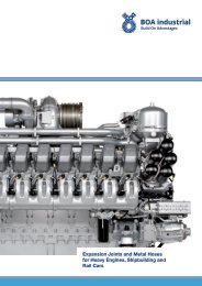
<strong>BOA</strong> universal expansion joints in a truck exhaust system<br />
Pipe guides<br />
No pipe weight shall load the expansion joint.<br />
Pipe guides must be installed where a straight pipe routing is wanted (see installation example).<br />
The pipe guides installed adjacent to the expansion joint must be strong enough to withstand the forces imposed on them by the expansion<br />
joint.<br />
Installation examples:<br />
Prerestraint<br />
The indicated axial and lateral movements must not be exceeded. In case of asymmetrical movements, the axial or lateral displacement capacity<br />
can no longer be fully used. Hence, while installing, the expansion joint should be prerestrained into the position which corresponds to<br />
the installation temperature. As the temperature of the pipe at the moment of the installation seldom corresponds to the lowest operating temperature,<br />
it is advisable to give some prerestraint values in the assembly plans corresponding to various temperature levels.<br />
Torsion<br />
The expansion joints must never be subject to torsion. This should particularly be considered when welding in counter flanges.<br />
Movement splitting axial / lateral<br />
The movements indicated in the tables are maximum values. In order to<br />
achieve the full load cycles required, only one of the movements can be fully<br />
used. If axial and lateral movements occur simultaneously, the permissible<br />
combination has to be determined by the diagram beside.<br />
The maximum movements, taken from the diagram, form the corners of the<br />
triangle motion (or the movement limiting line) within whose boundaries any<br />
movement combination can be established for the corresponding service life.<br />
Calculation example<br />
given: Type UFS 6-20, DN 200, 1000 full load cycles<br />
requested: lateral movement ± 40mm<br />
3