Computational Mechanics Research and Support for Aerodynamics ...
Computational Mechanics Research and Support for Aerodynamics ... Computational Mechanics Research and Support for Aerodynamics ...
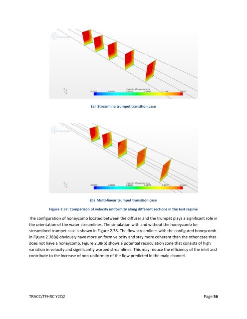
Figure 2.36: Comparison of velocity uniformity along different sections Figure 2.37 shows the cross-sectional velocity contour at the potential testing section in the main channel. Figure 2.37(a) is the result from a smoothly curved trumpet, while Figure 2.37(b) is from a multi-linear trumpet. It illustrates that the “streamlined” version of the trumpet design produces a more uniform velocity distribution than the multi-linear one does along a long stretch of the straight channel downstream. TRACC/TFHRC Y2Q2 Page 55
(a) Streamline trumpet transition case (b) Multi-linear trumpet transition case Figure 2.37: Comparison of velocity uniformity along different sections in the test regime The configuration of honeycomb located between the diffuser and the trumpet plays a significant role in the orientation of the water streamlines. The simulation with and without the honeycomb for streamlined trumpet case is shown in Figure 2.38. The flow streamlines with the configured honeycomb in Figure 2.38(a) obviously have more uniform velocity and stay more coherent than the other case that does not have a honeycomb. Figure 2.38(b) shows a potential recirculation zone that consists of high variation in velocity and significantly warped streamlines. This may reduce the efficiency of the inlet and contribute to the increase of non-uniformity of the flow predicted in the main channel. TRACC/TFHRC Y2Q2 Page 56
- Page 5 and 6: List of Figures Figure 2.1: Bridge
- Page 7 and 8: Figure 2.35: Two different transiti
- Page 9 and 10: 1. Introduction and Objectives The
- Page 11 and 12: 2. Computational Fluid Dynamics for
- Page 13 and 14: flat surface assumption is good exc
- Page 15 and 16: conditions from Example 1 defined i
- Page 17 and 18: scour rate is initially highest nea
- Page 19 and 20: Figure 2.6 Dividing streamline posi
- Page 21 and 22: 2.1.3. Resolving Issues of the Seco
- Page 23 and 24: educe the rate of increase for y wh
- Page 25 and 26: Design Scour Depth 0.400 0.350 0.30
- Page 27 and 28: extend the impact of the findings t
- Page 29 and 30: Table 2.2 Contour plots comparing C
- Page 31 and 32: Figure 2.14 Comparison of CFD and P
- Page 33 and 34: Figure 2.16 Comparison of CFD and P
- Page 35 and 36: Figure 2.18 Comparison of CFD and P
- Page 37 and 38: consistent with the lab test setup,
- Page 39 and 40: Figure 2.22 Comparison of CFD and P
- Page 41 and 42: Figure 2.24 Comparison of CFD and P
- Page 43 and 44: Figure 2.26 Comparison of CFD and P
- Page 45 and 46: Figure 2.28 Comparison of CFD and P
- Page 47 and 48: Figure 2.30 Comparison of CFD and P
- Page 49 and 50: Figure 2.32 Comparison of CFD and P
- Page 51 and 52: RMSD area area ( V1 V2 ) n area 2
- Page 53 and 54: 2. Marian Muste, Hao-Che Ho, Daniel
- Page 55: Honeycomb Streamline Trumpet Unifor
- Page 59 and 60: 2.6. Training and Technology Transf
- Page 61: Figure 2.40: Announcement for CFD t
(a) Streamline trumpet transition case<br />
(b) Multi-linear trumpet transition case<br />
Figure 2.37: Comparison of velocity uni<strong>for</strong>mity along different sections in the test regime<br />
The configuration of honeycomb located between the diffuser <strong>and</strong> the trumpet plays a significant role in<br />
the orientation of the water streamlines. The simulation with <strong>and</strong> without the honeycomb <strong>for</strong><br />
streamlined trumpet case is shown in Figure 2.38. The flow streamlines with the configured honeycomb<br />
in Figure 2.38(a) obviously have more uni<strong>for</strong>m velocity <strong>and</strong> stay more coherent than the other case that<br />
does not have a honeycomb. Figure 2.38(b) shows a potential recirculation zone that consists of high<br />
variation in velocity <strong>and</strong> significantly warped streamlines. This may reduce the efficiency of the inlet <strong>and</strong><br />
contribute to the increase of non-uni<strong>for</strong>mity of the flow predicted in the main channel.<br />
TRACC/TFHRC Y2Q2 Page 56


