Computational Mechanics Research and Support for Aerodynamics ...
Computational Mechanics Research and Support for Aerodynamics ...
Computational Mechanics Research and Support for Aerodynamics ...
- No tags were found...
You also want an ePaper? Increase the reach of your titles
YUMPU automatically turns print PDFs into web optimized ePapers that Google loves.
flat surface assumption is good except in the case with the bridge deck very close to the surface but still<br />
overtopped. The inlet boundary was taken to be a uni<strong>for</strong>m velocity located just at the outlet of the<br />
honeycomb in the TFHRC scour flume. The honeycomb is a flow straightener that also strips off<br />
boundary layers, <strong>and</strong> there<strong>for</strong>e the uni<strong>for</strong>m inlet velocity is a reasonably good assumption applied at<br />
this position.<br />
2.1.1. Testing the Theoretical Model <strong>for</strong> Pressure Flow Scour using CFD analysis, Initial Fit<br />
Testing of the theoretical model was conducted using data from Arneson [2], Umbrell [4], <strong>and</strong> TFHRC [3]<br />
<strong>and</strong> flow visualization using PIV <strong>and</strong> CFD modeling. The bulk of the material presented in this section<br />
pertains to the results of the CFD modeling <strong>and</strong> final tuning of the <strong>for</strong>mula <strong>for</strong> separation zone thickness,<br />
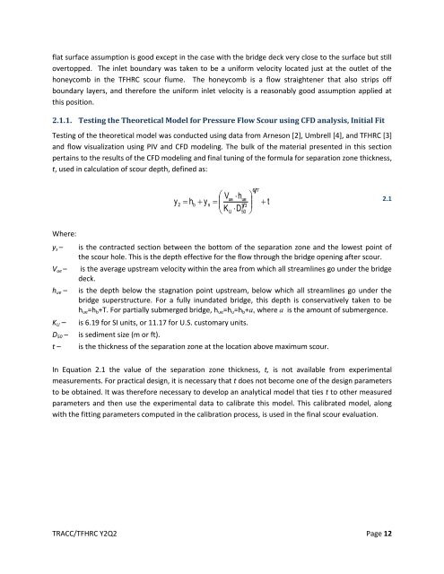
t, used in calculation of scour depth, defined as:<br />
6 7<br />
Vue<br />
h<br />
<br />
ue<br />
y<br />
2<br />
hb<br />
y<br />
s<br />
<br />
t<br />
1 3<br />
KU<br />
D<br />
<br />
<br />
50 <br />
2.1<br />
Where:<br />
y s –<br />
V ue –<br />
h ue –<br />
K U –<br />
D 50 –<br />
t –<br />
is the contracted section between the bottom of the separation zone <strong>and</strong> the lowest point of<br />
the scour hole. This is the depth effective <strong>for</strong> the flow through the bridge opening after scour.<br />
is the average upstream velocity within the area from which all streamlines go under the bridge<br />
deck.<br />
is the depth below the stagnation point upstream, below which all streamlines go under the<br />
bridge superstructure. For a fully inundated bridge, this depth is conservatively taken to be<br />
h ue =h b +T. For partially submerged bridge, h ue =h u =h b +a, where a is the amount of submergence.<br />
is 6.19 <strong>for</strong> SI units, or 11.17 <strong>for</strong> U.S. customary units.<br />
is sediment size (m or ft).<br />
is the thickness of the separation zone at the location above maximum scour.<br />
In Equation 2.1 the value of the separation zone thickness, t, is not available from experimental<br />
measurements. For practical design, it is necessary that t does not become one of the design parameters<br />
to be obtained. It was there<strong>for</strong>e necessary to develop an analytical model that ties t to other measured<br />
parameters <strong>and</strong> then use the experimental data to calibrate this model. This calibrated model, along<br />
with the fitting parameters computed in the calibration process, is used in the final scour evaluation.<br />
TRACC/TFHRC Y2Q2 Page 12


