HiPIMS
HiPIMS
HiPIMS
- No tags were found...

You also want an ePaper? Increase the reach of your titles
YUMPU automatically turns print PDFs into web optimized ePapers that Google loves.
<strong>HiPIMS</strong><br />
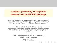
On the Plasma Parameters in the High Power<br />
Impulse Magnetron Sputtering Discharge<br />
(<strong>HiPIMS</strong>)<br />
Jón Tómas Guðmundsson<br />
Science Institute, University of Iceland, Iceland<br />
Department of Electrical and Computer Engineering, University of Iceland, Iceland<br />
tumi@hi.is<br />
Linköpings Universitet, March 9. 2007
<strong>HiPIMS</strong><br />
Introduction<br />
The demand for new materials and layer structures has<br />
lead to development of more advanced sputtering systems<br />
One such sputtering system is the<br />
high power pulsed magnetron sputtering discharge<br />
(HPPMS)<br />
high power impulse magnetron sputtering discharge<br />
(<strong>HiPIMS</strong>)<br />
It gives high electron density and highly ionized flux of the<br />
sputtered material<br />
The energy of the ions can be tailored to obtain impinging<br />
particles with energies comparable to typical surface and<br />
molecular binding energies
<strong>HiPIMS</strong><br />
Planar Magnetron Sputtering Discharge<br />
A typical dc planar magnetron discharge operates at a<br />
pressure of 1 – 10 mTorr with a magnetic field strength of<br />
0.01 – 0.05 T and at cathode potentials 300 – 700 V<br />
Electron density in the substrate vicinity is in the range<br />
10 15 − 10 16 m −3<br />
low fraction of the sputtered material is ionized (∼ 1 %)<br />
the majority of ions are the ions of the inert gas<br />
additional ionization by a secondary discharge (rf or<br />
microwave)
<strong>HiPIMS</strong><br />
High Power Impulse Magnetron Sputtering (<strong>HiPIMS</strong>)<br />
In a conventional dc magnetron discharge<br />
the power density is limited by the<br />
thermal load on the target<br />
Most of the ion bombarding energy is<br />
transformed into heat at the target<br />
In unipolar pulsing the power supply is at<br />
low (or zero) power and then a high<br />
power pulse is supplied for a short period<br />
The high power pulsed magnetron<br />
sputtering discharge uses the same<br />
sputtering apparatus except the power<br />
supply
<strong>HiPIMS</strong><br />
<strong>HiPIMS</strong> - Power supply<br />
The high power pulsed discharge operates with a<br />
Cathode voltage in the range of 500-2000 V<br />
Current densities of 3-4 A/cm 2<br />
Power densities in the range of 1-3 kW/cm 2<br />
Frequency in the range of 50 – 500 Hz<br />
Duty cycle in the range of 0.5 – 5 %
<strong>HiPIMS</strong><br />
<strong>HiPIMS</strong> - Power supply<br />
0.5 mTorr (solid line), 2 mTorr (dashed line) and 20 mTorr (dot dashed line)<br />
The exact pulse shape is determined by the load<br />
the discharge formed<br />
it depends on the gas type and gas pressure<br />
(After Gudmundsson et al. (2002))
<strong>HiPIMS</strong><br />
<strong>HiPIMS</strong> - Electron density<br />
(After Bohlmark et al. (2005b))<br />
Temporal and spatial variation of the electron density<br />
Argon discharge at 20 mTorr with a titanium target<br />
The electron density in the substrate vicinity is of the order<br />
of 10 18 m −3
<strong>HiPIMS</strong><br />
<strong>HiPIMS</strong> - Electron density<br />
(After Gudmundsson et al. (2002)) (From Gylfason et al. (2005))<br />
The electron density versus time from the initiation of the<br />
pulse 9 cm below the target<br />
The pulse is 100 µs long and the average power 300 W<br />
Each peak travels with a fixed velocity through the chamber
<strong>HiPIMS</strong><br />
<strong>HiPIMS</strong> - Ionization fraction<br />
There have been conflicting reports on<br />
the ionized flux fraction<br />
70 % for Cu (Kouznetsov et al., 1999)<br />
40 % for Ti 0.5 Al 0.5 (Macák et al., 2000)<br />
9.5 % for Al (DeKoven et al., 2003)<br />
4.5 % for C (DeKoven et al., 2003)<br />
The degree of ionization<br />
90 % for Ti (Bohlmark et al., 2005a) (From Bohlmark et al. (2005a))
<strong>HiPIMS</strong><br />
<strong>HiPIMS</strong> - Ionization fraction<br />
To explore the ionization mechanism and the temporal<br />
behavior of the plasma parameters a time dependent<br />
global (volume averaged) model was developed<br />
The discharge is assumed to consist of<br />
electrons, e<br />
argon atoms in the ground state, Ar<br />
metastable argon atoms, Ar ∗<br />
argon ions, Ar +<br />
metal atoms, M<br />
metal ions, M +
<strong>HiPIMS</strong><br />
<strong>HiPIMS</strong> - Ionization fraction<br />
Metal ions are generated by electron impact ionization<br />
e + M −→ M + + 2e<br />
by Penning ionization by collision with an electronically<br />
excited argon atom<br />
by charge exchange<br />
Ar ∗ + M −→ M + + Ar + 2e<br />
Ar + + M −→ M + + Ar<br />
The metal ions are assumed to be lost by diffusion to solid<br />
surfaces such as the chamber walls
<strong>HiPIMS</strong><br />
<strong>HiPIMS</strong> - Ionization fraction<br />
Particle balance for metal ions<br />
dn m+<br />
dt<br />
= k miz n e n m<br />
} {{ }<br />
electron impact<br />
+ k P n Ar ∗n<br />
} {{ m + k<br />
} chexc n Ar +n<br />
} {{ m<br />
}<br />
Penning charge exchange<br />
− k wall,m+ n m+<br />
} {{ }<br />
loss to wall<br />
Particle balance for metal atoms<br />
dn m<br />
dt<br />
= γ sputh L u B n Ar +r 2 T<br />
R 2 L<br />
} {{ }<br />
sputtering from target<br />
+ γ selfsputh L u B,m n m+ rT<br />
2<br />
} R{{ 2 L }<br />
selfsputtering from target<br />
− k miz n e n<br />
} {{ m − k<br />
} P n Ar ∗n m − k<br />
} {{ } chexc n Ar +n m − k<br />
} {{ } diff,m n m<br />
} {{ }<br />
ionization Penning charge exchange loss to wall
<strong>HiPIMS</strong><br />
<strong>HiPIMS</strong> - Ionization fraction<br />
Particle balance for argon ions, Ar +<br />
dn Ar +<br />
dt<br />
= k iz n e n Ar + k exc,iz n e n Ar ∗ − k chexc n m n Ar + − k wall,Ar+ n Ar +<br />
Particle balance for metastable argon atoms, Ar ∗<br />
dn Ar ∗<br />
dt<br />
= k exc n e n Ar −(k exc,iz +k deexc )n e n Ar ∗−k loss,Ar ∗n Ar ∗−k P n Ar ∗n m<br />
Quasi-neutrality condition<br />
n e = n Ar + + n m+<br />
Power balance<br />
( )<br />
d 3<br />
dt 2 en eT e = P abs<br />
V − eE ck iz n Ar n e − ek wall,Ar +(E e + E i )n Ar +
<strong>HiPIMS</strong><br />
<strong>HiPIMS</strong> - Ionization fraction<br />
The temporal variation of the<br />
particle density and the electron<br />
temperature was obtained by<br />
solving the differential equations<br />
simultaneously and<br />
self-consistently<br />
We assume a discharge chamber<br />
of radius R = 15 cm and length<br />
L = 15 cm with a target of radius<br />
7.5 cm made of aluminum.<br />
The electron energy distribution is<br />
assumed to be Maxwellian<br />
The power pulse is the measured<br />
pulse at 10 mTorr (dash dot line)
<strong>HiPIMS</strong><br />
<strong>HiPIMS</strong> - Ionization fraction<br />
From Ehiasarian et al. (2002)<br />
The calculated electron and ion density<br />
versus time<br />
The measured<br />
emission from<br />
a discharge<br />
with a Cr target
<strong>HiPIMS</strong><br />
<strong>HiPIMS</strong> - Ionization fraction<br />
For aluminum<br />
The integrated ionized<br />
fraction is 97 %<br />
The integrated ionized<br />
flux fraction is 99 %<br />
For carbon<br />
The integrated ionized<br />
fraction is 89 %<br />
The integrated ionized<br />
flux fraction is 97 %
<strong>HiPIMS</strong><br />
<strong>HiPIMS</strong> - Ionization fraction<br />
The first 100 µs (while the<br />
pulse is “on”) electron<br />
impact ionization is the<br />
most effective process in<br />
creating metal ions<br />
Then charge exchange<br />
becomes the dominant<br />
process in creating metal<br />
ions
<strong>HiPIMS</strong><br />
<strong>HiPIMS</strong> - Ion energy<br />
The time averaged ion<br />
energy distribution for Ar +<br />
and Ti + ions<br />
The gas pressure was 3<br />
mTorr, pulse energy 3 J<br />
and 10 J and the target<br />
made of Ti<br />
The ion energy distribution<br />
is broad to over 100 eV<br />
About 50 % of the Ti +<br />
ions have energy > 20 eV (From Bohlmark et al. (2006))
<strong>HiPIMS</strong><br />
<strong>HiPIMS</strong> - Ionization fraction<br />
The ion flux versus time<br />
measured by a mass<br />
spectrometer (20 µs<br />
windows)<br />
The gas pressure was 3<br />
mTorr, pulse energy 8 J<br />
and the target made of Ti<br />
(From Bohlmark et al. (2006))
<strong>HiPIMS</strong><br />
<strong>HiPIMS</strong> - Deposition rate<br />
Several groups report on a significantly<br />
lower deposition rate for HIPIMS as<br />
compared to dcMS<br />
a factor of 2 lower deposition rate for Cu<br />
and Ti thin films (Bugaev et al., 1996)<br />
a factor of 4 – 7 lower deposition rate for<br />
reactive sputtering of TiO 2 from a Ti<br />
target (Davis et al., 2004)<br />
a factor of 3 - 4 lower deposition rate for<br />
reactive sputtering of AlO x from an Al<br />
target (Sproul et al., 2004)<br />
the reduction in deposition rate<br />
decreases with decreased magnetic<br />
confinement (weaker magnetic field)<br />
(Bugaev et al., 1996)
<strong>HiPIMS</strong><br />
<strong>HiPIMS</strong> - Deposition rate<br />
One explanation is that the sputtered material is ionized<br />
close to the target and many of the metallic ions will be<br />
attracted back to the target surface by the cathode potential<br />
A reduction in the deposition rate would occur mainly for<br />
metals with a low self-sputtering yield<br />
Maybe this can be reduced by optimized magnetic<br />
confinement
<strong>HiPIMS</strong><br />
Summary<br />
We reviewed the physics of the high power impulse<br />
magnetron sputtering discharge (HIPIMS)<br />
Power supply<br />
Essentially the same sputtering apparatus except for the<br />
power supply<br />
Electron density<br />
Roughly 2 orders of magnitude higher in the substrate<br />
vicinity than for a conventional dc magnetron sputtering<br />
discharge<br />
Plasma dynamics<br />
The peak electron density travels away from the target with<br />
fixed velocity
<strong>HiPIMS</strong><br />
Summary<br />
Ionization fraction<br />
Ionization fraction is high, mainly due to the high electron<br />
density<br />
The ions on the inert gas and the ions of the sputtered<br />
vapor are separated in time<br />
Deposition rate<br />
Deposition rate is lower than in a conventional dc<br />
magnetron sputtering discharge, maybe due to self<br />
sputtering
<strong>HiPIMS</strong><br />
References<br />
Bohlmark, J., Alami, J., Christou, C., Ehiasarian, A. P., and Helmersson, U. (2005a). Ionization of sputtered metals in<br />
high power pulsed magnetron sputtering. Journal of Vacuum Science and Technology A, 23(1):18–22.<br />
Bohlmark, J., Gudmundsson, J. T., Alami, J., Latteman, M., and Helmersson, U. (2005b). Spatial electron density<br />
distribution in a high-power pulsed magnetron discharge. IEEE Transactions on Plasma Science,<br />
33(2):346–347.<br />
Bohlmark, J., Latteman, M., Gudmundsson, J. T., Ehiasarian, A. P., Gonzalvo, Y. A., Brenning, N., and Helmersson,<br />
U. (2006). The ion energy distribution and ion flux composition from a high power impulse magnetron sputtering<br />
discharge. Thin Solid Films, 515(5) 1522 - 1526<br />
Bugaev, S. P., Koval, N. N., Sochugov, N. S., and Zakharov, A. N. (1996). Investigation of a high-current pulsed<br />
magnetron discharge initiated in the low-pressure diffuse arc plasma. In XVIIth International Symposium on<br />
Discharges and Electrical Insulation in Vacuum, 1996, pages 1074–1076, Berkeley, CA USA. IEEE.<br />
Davis, J. A., Sproul, W. D., Christie, D. J., and Geisler, M. (2004). High power pulse reactive sputtering of TiO 2 . In<br />
47th Annual Technical Conference Proceedings, pages 215–218, Dallas, TX, USA. Society of Vacuum Coaters.<br />
DeKoven, B. M., Ward, P. R., Weiss, R. E., Christie, D. J., Scholl, R. A., Sproul, W. D., Tomasel, F., and Anders, A.<br />
(2003). Carbon thin film deposition using high power pulsed magnetron sputtering. In 46th Annual Technical<br />
Conference Proceedings, pages 158–165, San Francisco, CA, USA. Society of Vacuum Coaters.<br />
Ehiasarian, A. P., New, R., Münz, W.-D., Hultman, L., Helmersson, U., and Kouznetzov, V. (2002). Influence of high<br />
power densities on the composition of pulsed magnetron plasmas. Vacuum, 65:147–154.<br />
Gudmundsson, J. T., Alami, J., and Helmersson, U. (2002). Spatial and temporal behavior of the plasma parameters<br />
in a pulsed magnetron discharge. Surface and Coatings Technology, 161(2-3):249–256.<br />
Gylfason, K. B., Alami, J., Helmersson, U., and Gudmundsson, J. T. (2005). Ion-acoustic solitary waves in a pulsed<br />
magnetron sputtering discharge. Journal of Physics D: Applied Physics, 38(18):3417–3421.
<strong>HiPIMS</strong><br />
Helmersson, U., Lattemann, M., Alami, J., Bohlmark, J., Ehiasarian, A. P., and Gudmundsson, J. T. (2005a). High<br />
power impulse magnetron sputtering discharges and thin film growth: A brief review. In 48th Annual Technical<br />
Conference Proceedings, pages 458 – 464, Denver, CO, USA. Society of Vacuum Coaters.<br />
Helmersson, U., Lattemann, M., Bohlmark, J., Ehiasarian, A. P., and Gudmundsson, J. T. (2005b). Ionized physical<br />
vapor deposition (IPVD): A review of technology and applications. Thin Solid Films 515(1):1–24.<br />
Kouznetsov, V., Macák, K., Schneider, J. M., Helmersson, U., and Petrov, I. (1999). A novel pulsed magnetron sputter<br />
technique utilizing very high target power densities. Surface and Coatings Technology, 122(2-3):290–293.<br />
Macák, K., Kouznetzov, V., Schneider, J. M., Helmersson, U., and Petrov, I. (2000). Ionized sputter deposition using<br />
an extremely high plasma density pulsed magnetron discharge. Journal of Vacuum Science and Technology A,<br />
18(4):1533–1537.<br />
Sproul, W. D., Christie, D. J., Carter, D. C., Tomasel, F., and Linz, T. (2004). Pulsed plasmas for sputtering<br />
applications. Surface Engineering, 20:174–176.