INSTABUS RADIO GATEWAY - Merten
INSTABUS RADIO GATEWAY - Merten
INSTABUS RADIO GATEWAY - Merten

You also want an ePaper? Increase the reach of your titles
YUMPU automatically turns print PDFs into web optimized ePapers that Google loves.
<strong>INSTABUS</strong> radio gateway<br />
„<strong>INSTABUS</strong> radio gatewayChapter 2:Interfaces/gatewaysArt. no.680999As at 07/022.3Gateways<br />
!<br />
Function<br />
C<br />
B<br />
Function description<br />
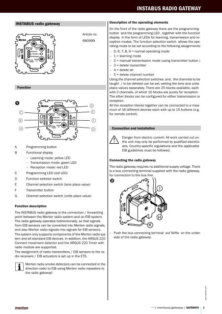
The <strong>INSTABUS</strong> radio gateway is the connection / forwarding<br />
point between the <strong>Merten</strong> radio system and an EIB system.<br />
The radio gateway operates bidirectionally, so that signals<br />
from EIB sensors can be converted into <strong>Merten</strong> radio signals,<br />
and also <strong>Merten</strong> radio signals into signals for EIB sensors.<br />
The system only supports components of the <strong>Merten</strong> radio system<br />
and all standard EIB devices. In addition, the ARGUS 220<br />
Connect movement detector and the ARGUS 220 Timer with<br />
radio module are supported.<br />
The assignment of radio transmitters / EIB sensors to the radio<br />
receivers / EIB actuators is set up in the ETS.<br />
| <strong>Merten</strong> radio smoke detectors can be connected in the<br />
Article no.<br />
680999<br />
A Programming button<br />
B Functional display<br />
– Learning mode: yellow LED<br />
– Transmission mode: green LED<br />
– Reception mode: red LED<br />
C Programming LED (red LED)<br />
D Function selector switch<br />
E Channel selection switch (tens place value)<br />
F Transmitter button<br />
G Channel selection switch (units place value)<br />
D<br />
E<br />
F<br />
A G<br />
direction radio to EIB using <strong>Merten</strong> radio repeaters to<br />
the radio gateway!<br />
<strong>INSTABUS</strong> <strong>RADIO</strong> <strong>GATEWAY</strong><br />
Description of the operating elements<br />
On the front of the radio gateway there are the programming<br />
button and the programming LED , together with the function<br />
display in the form of LEDs for learning, transmission and reception<br />
modes. The function selection switch allows the operating<br />
mode to be set according to the following assignments:<br />
– 0, 6, 7, 8, 9 = normal operating mode<br />
– 1 = learning mode<br />
– 2 = manual transmission mode (using transmitter button )<br />
– 3 = delete transmitter<br />
– 4 = delete all<br />
– 5 = delete channel number<br />
Using the channel selection switches and , the channels to be<br />
taught / to be deleted can be set, setting the tens and units<br />
place values separately. There are 25 blocks available, each<br />
with 2 channels, of which 10 blocks are purely for reception.<br />
The other blocks can be configured for either transmission or<br />
reception.<br />
All the reception blocks together can be connected to a maximum<br />
of 16 different devices each with up to 15 buttons (e.g.<br />
for remote control).<br />
Connection and installation<br />
½<br />
Danger from electric current: All work carried out on<br />
the unit may only be performed by qualified electricians.<br />
Country-specific regulations and the applicable<br />
EIB guidelines must be followed.<br />
Connecting the radio gateway<br />
The radio gateway requires no additional supply voltage. There<br />
is a bus connecting terminal supplied with the radio gateway,<br />
for connection to the bus line.<br />
"<br />
K<br />
– Push the bus connecting terminal auf Stifte on the underside<br />
of the radio gateway.<br />
I<br />
H<br />
©2004 | Interfaces/gateways | <strong>GATEWAY</strong>S<br />
1<br />
www.merten.com
<strong>INSTABUS</strong> <strong>RADIO</strong> <strong>GATEWAY</strong><br />
You can install the radio gateway in any size 60 installation box<br />
(flush-mounted box, cavity wall socket, cable duct socket...).<br />
½<br />
Caution: The radio gateway can be damaged. Be careful<br />
to maintain the distances from 230 V cables in the<br />
installation area, in accordance with the applicable<br />
standards and guidelines. Never install the radio<br />
gateway in a flush-mounted box where there are 230<br />
V cables.<br />
| Note: Metal surfaces in the immediate surroundings of<br />
C<br />
§<br />
§<br />
the radio gateway can affect reception and transmission<br />
properties. Therefore, if possible, do not install the<br />
radio gateway in a metal flush-mounted box.<br />
1 Antenna (grey core) should be laid behind the<br />
casing, so as to avoid interference with the radio signal<br />
by the retaining ring.<br />
2 Secure the retaining ring of the radio gateway to a<br />
flush-mounted box, using the screws supplied.<br />
Introduction to the subject<br />
For a better understanding of the operation of the radio gateway<br />
and its description in this instructions, we offer here an introduction<br />
to the terms employed.<br />
A distinction is made between terms that relate to signals on<br />
the radio side that are converted into signals for the EIB side<br />
(radio – EIB) and those that relate to signals from the EIB side<br />
that are converted into signals for the radio side (EIB – radio).<br />
Signals on the EIB side are always referred to as EIB telegrams,<br />
signals on the radio side are referred to as radio signals. The<br />
function of signals such as "On/dim brighter" or "Toggle" is set<br />
in the radio receiver.<br />
Furthermore, on the EIB side reference is always to actuators<br />
and sensors, on the radio side on the other hand always to<br />
transmitters and receivers.<br />
The radio gateway is divided into 25 blocks which can each be<br />
assigned a different function in the ETS. Each block is divided<br />
into two channels, by which the radio signals are transmitted<br />
or received.<br />
www.merten.com Installing the radio gateway<br />
2 <strong>GATEWAY</strong>S| Interfaces/gateways | ©2004<br />
Radio ➝ EIB<br />
D<br />
E<br />
J<br />
K<br />
A<br />
c<br />
F<br />
G<br />
L<br />
M<br />
P<br />
A Gateway<br />
B <strong>Merten</strong> radio<br />
C Radio gateway<br />
D Object A<br />
E Object B<br />
F Reception block 1<br />
G Toggle<br />
H Reception channel 1<br />
I Reception channel 2<br />
J Switch object<br />
K Dimming object<br />
L Reception block 2<br />
M Dimming<br />
N Reception channel 3<br />
O Reception channel 4<br />
P Max. 25 channels<br />
Q Transmitter button<br />
R Remote control<br />
The radio gateway receives in the direction of radio to EIB radio<br />
signals from the radio components. The blocks and channels<br />
in this direction of data transfer are referred to as reception<br />
blocks / reception channels. The radio transmitters are assigned<br />
to the reception blocks / reception channels.<br />
In this direction of data transfer there are a maximum of 25 reception<br />
blocks available, each with two reception channels. A<br />
maximum of 16 different radio transmitters, each with up to<br />
15 different transmitter buttons, can be taught to the reception<br />
channels.<br />
Each block can be assigned the following functions: Toggle<br />
(two per block), switch, dim, blind, pulse edge and ARGUS<br />
(each one per block).<br />
The odd-numbered reception channels each trigger toggle, off,<br />
dim down, move up telegrams to the EIB side for their respective<br />
functions.<br />
The even-numbered reception channels each trigger toggle,<br />
on, dim up, move down telegrams to the EIB side for their respective<br />
functions.<br />
H<br />
I<br />
N<br />
O<br />
B<br />
Q<br />
Q<br />
Q<br />
R
EIB ➝ radio<br />
D<br />
E<br />
J<br />
K<br />
A<br />
C<br />
F<br />
G<br />
L<br />
M<br />
P<br />
H<br />
I<br />
N<br />
O<br />
A Gateway<br />
B <strong>Merten</strong> radio<br />
C Radio gateway<br />
D Switch object<br />
E Dimming object<br />
F Transmission block 1<br />
G Dimming<br />
H Transmission channel 1<br />
I Transmission channel 2<br />
J Object A<br />
K Object B<br />
L Transmission block 2<br />
M Toggle<br />
N Transmission channel 3<br />
O Transmission channel 4<br />
P max. 15 blocks<br />
Q Receiver<br />
R Switch off (dimming)<br />
S Switch on (dimming)<br />
T Toggle<br />
In the data direction EIB to radio, the radio gateway transmits<br />
radio signals to the radio components. The blocks and channels<br />
in this direction of data transfer are referred to as transmission<br />
blocks / transmission channels. The radio receivers<br />
are assigned to the transmission blocks / transmission channels.<br />
In this direction of data transfer there are a maximum of 15<br />
transmission blocks available, each with two transmission<br />
channels. Each block can be assigned the following functions:<br />
Toggle (two per block), switch, dim and blind (each one per<br />
block).<br />
The odd-numbered transmission channels are pre-set in the<br />
application for the functions "Toggle", "Off", "Off/dim down" or<br />
"Blind down".<br />
The functions are set when linking the transmission channels<br />
to the radio receivers.<br />
The even-numbered transmission channels are pre-set in the<br />
application for the functions "Toggle", "On", "On/dim up" or<br />
"Blind up".<br />
The functions are set when linking the transmission channels<br />
to the radio receivers.<br />
B<br />
Q<br />
R<br />
Q<br />
S<br />
Q<br />
T<br />
Q<br />
T<br />
Commissioning<br />
<strong>INSTABUS</strong> <strong>RADIO</strong> <strong>GATEWAY</strong><br />
To start up the radio gateway you must first link the desired radio<br />
transmitters / radio receivers. Linked radio transmitters<br />
can be deleted again at any time.<br />
Enter all the parameters set in the ETS into a planning aid (see<br />
operating instructions). This planning aid is essential for completing<br />
the settings and assignments and for recreating them<br />
again as necessary.<br />
| All the item numbers to referred to in this section rela-<br />
te to figure !.<br />
Linking radio transmitters to the radio gateway (radio › EIB)<br />
For <strong>Merten</strong> radio signals to be transferred to the EIB in order<br />
for EIB telegrams to be issued (e.g. switch telegrams), the radio<br />
transmitter must be linked to the radio gateway. Once the<br />
radio transmitter is linked, the radio gateway acts on the radio<br />
side as a receiver. Several radio transmitters can be linked to<br />
a single reception channel, so that various radio buttons can<br />
be used to control any blind, for example.<br />
1 Set the two channel selection switches and to the<br />
desired reception channel.<br />
2 Set the function selector switch to "1" (learn).<br />
Learn mode will be activated, and the yellow LED will start to<br />
flash. You now have approx. 3 minutes in which to activate the<br />
desired radio transmitter.<br />
| All radio transmitters for which the transmitter button is<br />
pressed within the next 3 minutes will be linked.<br />
3 Press the transmitter button on the desired radio<br />
transmitter to which you wish this channel to be linked.<br />
When the radio gateway has received the transmitted signal<br />
and identified it, the yellow LED will light up for approx. 1 second.<br />
You now have a further 3 minutes in which to link another<br />
radio transmitter by pressing the transmitter button on<br />
that transmitter to this reception channel. The yellow LED will<br />
start to flash again.<br />
| Only for ARGUS: If you wish to link transmitters that<br />
have the ARGUS radio module (e.g. ARGUS Connect),<br />
then set the coding switch on the radio module to "H"<br />
(transmit radio link signal). The radio module will thereupon<br />
transmit a link-up radio signal every three seconds.<br />
When the link-up is successful, the yellow LED<br />
will light up for approx. 1 second. Then set the coding<br />
switch on the ARGUS radio module back to "A" (normal<br />
mode).<br />
4 Once you have linked all transmitters to the selected<br />
reception channel, return the function selection<br />
switch to "0" (normal operation).<br />
5 Use the ETS to assign an EIB function including parameters<br />
and objects (e.g. switch, blind etc.) to the<br />
reception channel of the radio gateway.<br />
6 Enter all the settings and allocations selected into<br />
the planning aid.<br />
©2004 | Interfaces/gateways | <strong>GATEWAY</strong>S<br />
3<br />
www.merten.com
<strong>INSTABUS</strong> <strong>RADIO</strong> <strong>GATEWAY</strong><br />
If <strong>Merten</strong> radio receivers should be controlled using EIB telegrams<br />
(e.g. blind), you must link the radio gateway to the radio<br />
receiver, which thereafter will act on the radio side as a transmitter.<br />
You can link the radio gateway to several radio receivers on various<br />
transmission channels and then make all the EIB settings<br />
retrospectively using ETS.<br />
1 Set the two channel selection switches and to the<br />
desired transmission channel, from 1 to 30.<br />
2 Set the function selector switch to "2" (manual<br />
transmission).<br />
3 Set the desired radio receiver to the desired function<br />
(see the instructions for the receiver concerned).<br />
You now have a certain length of time (dependent on the radio<br />
receiver) to send a radio signal using the radio gateway.<br />
4 Press the transmitter button .<br />
The radio gateway will transmit a short radio signal, and the<br />
green LED B (transmit mode) will light up. When the receiver<br />
receives the transmission signal and has identified it, it signals<br />
this by briefly switching on the load connected (e.g. blinds<br />
move up and down slightly).<br />
5 Set the function selector switch back to "0" (normal<br />
operation).<br />
6 Put the radio receiver back into operating mode<br />
(see the instructions for the receiver concerned).<br />
7 Use ETS to assign functions to the transmission<br />
blocks including parameters and objects, (e.g. switching,<br />
blinds etc.).<br />
8 Enter all the settings and allocations selected into<br />
the planning aid.<br />
| A description of another link-up method, in which the<br />
EIB buttons are parameterised in advance, can be<br />
found on the Internet under www.merten.de.<br />
Deletion operations<br />
In the data direction from radio to EIB you have four different<br />
options for deleting radio transmitters that are saved in the radio<br />
gateway:<br />
1. Delete a certain transmitter button from a reception channel.<br />
2. Delete all radio transmitters linked to a particular reception<br />
channel<br />
3. Delete all transmitter buttons of a radio transmitter<br />
4. Delete everything<br />
In the data direction from EIB to radio you have one option for<br />
deletion:<br />
1. Delete the radio gateway from a radio receiver<br />
www.merten.com Linking the radio gateway to the radio receiver (EIB ➝ radio)<br />
4 <strong>GATEWAY</strong>S| Interfaces/gateways | ©2004<br />
Delete a certain transmitter button from a reception channel<br />
(radio ➝ EIB)<br />
If you have linked a particular transmitter button on a radio<br />
transmitter to a reception channel and with to delete this<br />
again, proceed as follows:<br />
1 Set the two channel selection switches and to the<br />
reception channel that it is desired to delete.<br />
2 Set the function selector switch to "5" (delete channel<br />
number).<br />
3 Press the transmitter button on the radio transmitter.<br />
This transmitter button on this radio transmitter is deleted. All<br />
other transmitter buttons on this reception channel remain saved.<br />
4 Set the function selector switch back to "0" (normal<br />
operation).<br />
5 Enter all the settings and allocations selected into<br />
the planning aid.<br />
Delete all radio transmitters linked to a particular reception<br />
channel (radio ➝ EIB)<br />
If you wish to delete several radio transmitters that are linked<br />
to a single reception channel on the radio gateway (e.g. several<br />
radio buttons all switching a lamp) and you wish to delete the<br />
entire reception channel, proceed as follows:<br />
1 Set the two channel selection switches and to the<br />
reception channel that it is desired to delete.<br />
2 Set the function selector switch to "5" (delete channel<br />
number).<br />
3 Press the transmitter button on the radio gateway.<br />
The set reception channel will be completely deleted, i.e. all<br />
transmitters that have a transmitter button linking them to this<br />
reception channel on the radio gateway are deleted from the<br />
radio gateway memory.<br />
4 Set the function selector switch back to "0" (normal<br />
operation).<br />
5 Enter all the settings and allocations selected into<br />
the planning aid.<br />
Delete all transmitter buttons of a radio transmitter (radio ➝<br />
EIB)<br />
If you wish to completely delete a radio transmitter from the radio<br />
gateway memory, so that the radio gateway does not respond<br />
to any further radio signals, then proceed as follows:<br />
1 Set the function selector switch to "3" (delete transmitter).<br />
2 Press a transmitter button on the radio transmitter.<br />
The radio transmitter has now been completely deleted from<br />
the radio gateway memory.<br />
3 Set the function selector switch back to "0" (normal<br />
operation).<br />
4 Enter all the settings and allocations selected into<br />
the planning aid.
Delete everything (radio › EIB)<br />
If you wish to delete all the linked radio transmitters on all reception<br />
channels, proceed as follows:<br />
1 Set the function selector switch to "4" (delete everything).<br />
2 Press any transmitter button on any radio transmitter<br />
(does not have to be linked to the radio gateway).<br />
The reception channel memory has now been completely deleted<br />
from the radio gateway.<br />
3 Set the function selector switch back to "0" (normal<br />
operation).<br />
Delete the radio gateway from a radio receiver (EIB ➝ radio)<br />
If you wish to delete the radio gateway from a radio receiver,<br />
proceed as follows:<br />
1 Set the function selector switch to "2" (manual<br />
transmission mode).<br />
2 Set the coding switch of the respective radio receiver<br />
to the "Transmitter delete" position (e.g. Fg for<br />
deleting the transmitter for the universal dimmer).<br />
3 Press the transmitter button , the green transmit<br />
LED will light up.<br />
The radio gateway is now completely deleted from this radio receiver.<br />
4 Set the function selector switch back to "0" (normal<br />
operation).<br />
Technical data<br />
<strong>INSTABUS</strong> <strong>RADIO</strong> <strong>GATEWAY</strong><br />
Radio transmitter<br />
Transmission channels: 30<br />
Frequency: 868 MHz<br />
Transmission capacity: max. 10 mW<br />
Receiver<br />
Reception channels: 50<br />
Display elements: – green LED for transmission<br />
mode<br />
– yellow LED for reception<br />
mode<br />
– red LED as programming indicator<br />
Operating elements: one programming button, two<br />
channel selection switches for<br />
max. 50 radio receivers, one<br />
function selection switch (normal<br />
operation, learning mode,<br />
manual transmission mode,<br />
four different deletion modes)<br />
Transmission range<br />
in free field: up to approx. 100 m<br />
within a building: up to approx. 30 m (depending<br />
on building materials)<br />
Ambient temperature<br />
Operation: -5 C to +45 C<br />
Storage: -25 C to +55 C<br />
Transport: -25 C to +70 C<br />
Max. humidity: 93 %<br />
Casing dimensions: approx. 50x44x33 mm, without<br />
antenna and retaining<br />
ring<br />
Connection to the bus by: 2 pins for bus connecting terminal<br />
External auxiliary voltage<br />
Power supply from the 24 V DC / approx. < 10 mA<br />
bus:<br />
The radio gateway is approved for D, NL, B, LUX, A, CH, P, E, I.<br />
©2004 | Interfaces/gateways | <strong>GATEWAY</strong>S<br />
5<br />
www.merten.com
<strong>INSTABUS</strong> <strong>RADIO</strong> <strong>GATEWAY</strong><br />
Settings in the EIB Tool Software (ETS)<br />
Manufacturer: <strong>Merten</strong><br />
Product family: 1.3 Interfaces/gateways<br />
Product type: 1.3.11 Radio gateway, flush-mounted<br />
Program name: Switching/dimming/blind<br />
7302/1.0<br />
Media type: Twisted Pair<br />
Product name: Flush-mounted <strong>INSTABUS</strong> radio gateway<br />
Order number: 680999<br />
Application overview<br />
The following application is available:<br />
Application Vers. Function<br />
Switching/dimming/ 1.0 of EIB to radio (block 1 to 15):<br />
blind 7302/1.0<br />
Send toggle commands<br />
Send switching commands<br />
Send dimming commands<br />
Send blind control commands<br />
of radio to EIB (block 1 to 25):<br />
Send toggle commands<br />
Send switching commands<br />
Send dimming commands<br />
Send blind control commands<br />
Send edge commands<br />
ARGUS<br />
Dynamic management of group addresses<br />
Maximum group addresses and associations: 118 with max.<br />
50 communication objects.<br />
www.merten.com Selection in the product database<br />
6 <strong>GATEWAY</strong>S| Interfaces/gateways | ©2004
1. Settings in the EIB Tool Software (ETS)<br />
Selection in the product database<br />
Manufacturer: <strong>Merten</strong><br />
Product family: 1.3 Interfaces / gateways<br />
Product type: 1.3.11 Radio gateway UP<br />
Programs in connection with<br />
integrated bus coupler:<br />
Switching/dimming/blind<br />
7302/1.0<br />
Media type: Twisted Pair<br />
Product name: <strong>INSTABUS</strong> radio gateway UP<br />
Order number: 6809 99<br />
2. Application overview<br />
Application Vers. Function Page<br />
Switching/dimming/<br />
blind 7302/1.0<br />
1.0 from EIB to radio<br />
(Block 1 to 15):<br />
Send toggle commands 69<br />
Send switching commands 70<br />
Send dimming commands 70<br />
Send shutter commands<br />
from radio to EIB<br />
(Block 1 to 25):<br />
70<br />
Send toggle commands 71<br />
Send switching commands 71<br />
Send dimming commands 72<br />
Send shutter commands 72<br />
Send pulse edge commands 73<br />
ARGUS 74<br />
Dynamic administration of group addresses<br />
Maximum no. of group addresses and allocations: 118<br />
with max. 50 communication objects.<br />
<strong>INSTABUS</strong> <strong>RADIO</strong> <strong>GATEWAY</strong><br />
3. Switching/dimming/blind 7302/1.0<br />
3.1 from EIB to radio<br />
In the direction from EIB to radio, only transmitter blocks<br />
1 to 15 are available.<br />
●Send toggle commands . . . . . . . . . .EIB → Radio<br />
BUS<br />
Two groups of radio receivers can be addressed per<br />
transmitter block.<br />
Switching and value objects are evaluated. When a<br />
telegram is received at the EIB object, the gateway<br />
sends a radio signal to the assigned radio receiver. The<br />
radio receivers carry out the reverse procedure for every<br />
radio signal. Loads which are switched on will be<br />
switched off – loads which were switched off will be<br />
switched on. This switching behaviour is called<br />
"toggling".<br />
| Requirement: When the radio gateway was<br />
connected, the "Toggle" function was set at the<br />
radio receivers<br />
(see operating instructions for the radio receiver<br />
concerned).<br />
| The "Toggle" function is not suitable for group<br />
functions since the status of the loads after<br />
toggling depends on their status beforehand.<br />
Please note that status reports are not available<br />
with radio, including for individual functions. The<br />
"Toggle" function is therefore only recommended<br />
when the loads can be monitored.<br />
Communication objects<br />
Obj Function Com.objects Type Prio Flags Behaviour<br />
0 -<br />
29<br />
Block 1 -15 Switch object 1 bit low WC Send<br />
0 -<br />
29<br />
EIS1<br />
EIS6<br />
Block 1 -15 Value object<br />
A/B<br />
Parameter<br />
Umschalten<br />
Objekt A<br />
Objekt B<br />
'1', '0'<br />
'F0', '00'<br />
Sende-<br />
Kanal 1<br />
Sende-<br />
Kanal2<br />
1<br />
byte<br />
Emfänger<br />
Umschalten<br />
low WC Send<br />
Parameter Setting<br />
Data direction from EIB to radio (transmitter)<br />
Selection of function Toggle<br />
Number of objects one<br />
two<br />
Object A (transmit channel 1) 1 bit<br />
1 byte (in steps 0% - 100% /<br />
cont. 0 - 255)<br />
Object B (transmit channel 2) 1 bit<br />
(only when number of objects = 1 byte (in steps 0% - 100% /<br />
2)<br />
cont. 0 - 255)<br />
Example:<br />
Block 1 = radio transmitter<br />
(toggle)<br />
when number of objects = 1 Transmit channel 1 (Toggle) /<br />
Transmit channel 2 (none)<br />
Um<br />
Um<br />
Emfänger<br />
Umschalten<br />
©2004 | Interfaces/gateways | <strong>GATEWAY</strong>S<br />
7<br />
www.merten.com
<strong>INSTABUS</strong> <strong>RADIO</strong> <strong>GATEWAY</strong><br />
●Send switching commands. . . . . . . EIB → Radio<br />
www.merten.com<br />
BUS<br />
BUS<br />
Parameter Setting<br />
when number of objects = 2 Transmit channel 1 (Toggle) /<br />
Transmit channel 2 (Toggle)<br />
EIS1<br />
One group of radio receivers can be addressed per<br />
transmitter block.<br />
Depending on the object value sent by the EIB sensor,<br />
the radio receiver switches to either OFF or ON. The odd<br />
channel number is preset in ETS for the radio signal<br />
"Switch OFF"; the even channel number is preset for the<br />
radio signal "Switch ON".<br />
Communication objects<br />
Obj Function Com.objects Type Prio Flags Behaviour<br />
0 -<br />
28<br />
Block 1 -15 Switch object 1 bit low WC Send<br />
Parameter<br />
Schalten<br />
Schaltobjekt<br />
"tot"<br />
Sende-<br />
Kanal 1<br />
Parameter Setting<br />
Data direction from EIB to radio (transmitter)<br />
Selection of function<br />
Example:<br />
Switch<br />
Block 1 = radio transmitter Transmit channel 1 (Off) /<br />
(switching)<br />
Transmit channel 2 (On)<br />
●Send dimming commands . . . . . . . EIB → Radio<br />
EIS2<br />
Dimmen<br />
Schalt-<br />
Objekt<br />
One group of radio receivers can be addressed per<br />
transmitter block.<br />
The EIB sensor must always send a stop signal since<br />
values (i.e. dimming stages) cannot be sent via radio.<br />
The radio receiver evaluates the operating time of the<br />
sensor. If the sensor is operated for a longer period of<br />
time, the radio receiver will dim; if it is operated for a<br />
shorter period, the radio receiver will switch. The odd<br />
channel number is preset in ETS for the radio signal<br />
"Switch OFF / dim down"; the even channel number is<br />
preset for the radio signal "Switch ON / dim up".<br />
| The "Send dimming commands" function is not<br />
suitable for group functions since the status of<br />
the loads after toggling depends on their status<br />
beforehand.<br />
Please note that status reports are not available<br />
with radio, including for individual functions. The<br />
"Send dimming commands" function is therefore<br />
only recommended when the loads can be<br />
monitored.<br />
Communication objects<br />
The following communication objects can be selected:<br />
8 <strong>GATEWAY</strong>S| Interfaces/gateways | ©2004<br />
"0"<br />
"1"<br />
Sende-<br />
Kanal 2<br />
Aus /<br />
dunkler Sende-<br />
Kanal 1<br />
Dimm-<br />
Sende-<br />
EIS2 Ein /<br />
Objekt<br />
Kanal2<br />
heller<br />
Aus<br />
Ein<br />
Aus<br />
Ein<br />
Emfänger<br />
Ausschalten<br />
Einschalten<br />
Emfänger<br />
Runterdimm.<br />
Hochdimmen<br />
Obj Function Com.objects Type Prio Flags Behaviour<br />
0 -<br />
28<br />
Block 1 -15 Switch object 1 bit low WC Send<br />
1 -<br />
29<br />
Block 1 -15 Dimming object 4 bit low WC Send<br />
Parameter<br />
Parameter Setting<br />
Data direction from EIB to radio (transmitter)<br />
Selection of function<br />
Example:<br />
Dimming<br />
Block 1 = radio transmitter Transmit channel 1 (Off) /<br />
(dimming)<br />
Transmit channel 2 (On)<br />
●Send shutter commands . . . . . . . . .EIB → Radio<br />
BUS<br />
One group of radio receivers can be addressed per<br />
transmitter block.<br />
The radio receiver evaluates the operating time of the<br />
sensor. When the sensor is operated for a longer period,<br />
the radio receiver raises or lowers the blind; when it is<br />
operated for a shorter period, it stops the movement of<br />
the blind (only when it is moving) or changes the<br />
position of the louvres. The odd channel number is<br />
preset in ETS for the radio signal "Raise / Adjust louvres<br />
and stop"; the even channel number is preset for the<br />
radio signal "Lower / Adjust louvres and stop".<br />
Communication objects<br />
The following communication objects can be selected:<br />
Obj Function Com.objects Type Prio Flags Behaviour<br />
0 -<br />
28<br />
1 -<br />
29<br />
EIS7<br />
EIS7<br />
Block 1 -15 Stop/step<br />
object<br />
Block 1 -15 Movement<br />
object<br />
Parameter<br />
Jalousie<br />
Stop-<br />
Schritt-<br />
Obj<br />
Beweg-<br />
Objekt<br />
Auf<br />
Ab<br />
Sende-<br />
Kanal 1<br />
Sende-<br />
Kanal2<br />
Emfänger<br />
Aufwärts<br />
Abwärts<br />
1 bit low WC Receive<br />
1 bit low WC Receive<br />
Parameter Setting<br />
Data direction from EIB to radio (transmitter)<br />
Selection of function Shutter<br />
Example:<br />
Block 1 = radio transmitter (blind) Transmit channel 1 (Up) /<br />
Transmit channel 2 (Down)<br />
Auf<br />
Ab
3.2 from radio to EIB<br />
●Send toggle commands . . . . . . . . . Radio → EIB<br />
BUS<br />
Two groups of radio transmitters per receiver block can<br />
be connected for single-button switching.<br />
For every radio signal received, a toggle telegram with<br />
the inverse value will be created. In the case of switch<br />
objects, toggling is between 1 and 0; for value objects,<br />
toggling is between two adjustable values.<br />
| The "Toggle" function is not suitable for group<br />
functions since the status of the loads after<br />
toggling depends on their status beforehand.<br />
Please note that status reports are not available<br />
with radio, including for individual functions. The<br />
"Send toggle commands" function is therefore<br />
only recommended when the loads can be<br />
monitored.<br />
Communication objects<br />
Obj Function Com.objects Type Prio Flags Behaviour<br />
0 -<br />
49<br />
0 -<br />
49<br />
EIS1<br />
EIS6<br />
Block 1 - 25 Switch object<br />
A/B<br />
Block 1 - 25 Value object<br />
A/B<br />
Parameter<br />
Umschalten<br />
Schalt-<br />
Ein/Aus<br />
Objekt<br />
Wert-<br />
Objekt<br />
FF/00<br />
Empfangs<br />
Kanal 1<br />
Empfangs<br />
Kanal 2<br />
1 bit low WC Send<br />
1<br />
byte<br />
low WC Send<br />
Sender<br />
Sender<br />
Parameter Setting<br />
Data direction from radio to EIB<br />
(Receiver)<br />
Selection of function Toggle<br />
Number of objects one<br />
two<br />
Object A (receive channel 1) 1 bit<br />
1 byte (in steps 0% - 100% /<br />
cont. 0 - 255)<br />
Object B (receive channel 2) 1 bit<br />
(only when number of objects =<br />
2)<br />
1 byte (in steps 0% - 100% /<br />
cont. 0 - 255)<br />
Value 1 from object type A/B 100 %<br />
(only visible when object type<br />
A/B = 1 byte in steps)<br />
adjustable in steps of ten as well<br />
as 25 % and 75 %<br />
Value 2 from object type A/B 0 %<br />
(only visible when object type<br />
A/B = 1 byte in steps)<br />
adjustable in steps of ten as well<br />
as 25 % and 75 %<br />
Value 1 from object type A/B 255<br />
(only visible when object type<br />
A/B = 1 byte continuously)<br />
adjustable in steps of one<br />
Value 2 from object type A/B 0<br />
(only visible when object type<br />
A/B = 1 byte continuously)<br />
adjustable in steps of one<br />
<strong>INSTABUS</strong> <strong>RADIO</strong> <strong>GATEWAY</strong><br />
●Send switching commands . . . . . . .Radio → EIB<br />
BUS<br />
Two groups of radio transmitters per receiver block can<br />
be connected for two-button switching.<br />
Depending on the radio signal received, either an ON or<br />
an OFF telegram will be created. The radio transmitter<br />
which is connected to the odd-numbered channel<br />
creates the OFF telegram, and the radio transmitter<br />
connected to the even-numbered channel creates the<br />
ON telegram (switch object=1 bit).<br />
The setting switch object =1 byte in steps or 1 byte<br />
continuously can be used to transfer switching<br />
telegrams with freely selectable values 1 and 2, e. g. to<br />
switch a dimming actuator directly to particular<br />
brightness values. The radio transmitter which is<br />
connected to the odd-numbered channel creates the<br />
telegram with the value 1, and the radio transmitter<br />
connected to the even-numbered channel creates the<br />
telegram with the value 2.<br />
Communication objects<br />
Obj Function Com.objects Type Prio Flags Behaviour<br />
0 -<br />
48<br />
EIS1<br />
Block 1 -<br />
25<br />
Parameter<br />
Schalten<br />
Schalt-<br />
Objekt<br />
"tot"<br />
Aus<br />
Ein<br />
Empfangs<br />
Kanal 1<br />
Empfangs<br />
Kanal 2<br />
Switch object/<br />
Value object<br />
1 bit/<br />
1<br />
byte<br />
Sender<br />
Sender<br />
low CT Send<br />
Parameter Setting<br />
Data direction from radio to EIB<br />
(Receiver)<br />
Selection of function Switch<br />
Switch object 1 bit<br />
1 byte (in steps 0% - 100% /<br />
cont. 0 - 255)<br />
Value 1<br />
100 %<br />
(only visible when switch object<br />
= 1 byte in steps)<br />
adjustable in steps of ten as well<br />
as 25 % and 75 %<br />
Value 2<br />
0 %<br />
(only visible when switch object<br />
= 1 byte in steps)<br />
adjustable in steps of ten as well<br />
as 25 % and 75 %<br />
Value 1<br />
255<br />
(only visible when switch object<br />
= 1 byte continuously)<br />
adjustable in steps of one<br />
Value 2<br />
0<br />
(only visible when switch object<br />
= 1 byte continuously)<br />
adjustable in steps of one<br />
©2004 | Interfaces/gateways | <strong>GATEWAY</strong>S<br />
9<br />
www.merten.com
<strong>INSTABUS</strong> <strong>RADIO</strong> <strong>GATEWAY</strong><br />
●Send dimming commands . . . . . . . Radio → EIB<br />
www.merten.com<br />
BUS<br />
BUS<br />
Single button<br />
EIS2<br />
EIS2<br />
Dimm-<br />
Objekt<br />
Two groups of radio transmitters per receiver block can<br />
be connected for single-button switching.<br />
A received radio signal creates either an ON/OFF<br />
telegram or a dim up / dim down telegram. A short radio<br />
signal triggers the ON/OFF telegram, a long radio signal<br />
triggers a dim up / dim down telegram. After the end of<br />
a long radio signal, a stop command is created to stop<br />
the dimming procedure.<br />
| The "Single-button dimming" function is not<br />
suitable for group functions since the status of<br />
the loads after toggling depends on their status<br />
beforehand.<br />
Please note that status reports are not available<br />
with radio, including for individual functions. The<br />
"Send dimming commands" function is therefore<br />
only recommended when the loads can be<br />
monitored.<br />
Two buttons<br />
EIS2<br />
EIS2<br />
Dimmen<br />
Schalt- Ein/Aus<br />
Objekt<br />
Dimmen<br />
Schalt-<br />
Objekt<br />
Dimm-<br />
Objekt<br />
runter/<br />
hoch<br />
Empfangs<br />
Kanal 1<br />
Empfangs<br />
Kanal 2<br />
Aus / Empfangs<br />
dunkler<br />
Kanal 1<br />
Empfangs<br />
Ein / Kanal 2<br />
heller<br />
With two-button dimming, two groups of radio<br />
transmitters can be connected per receiver block.<br />
Depending on the radio signal received, either an ON/<br />
OFF telegram or a dim up / dim down telegram will be<br />
created.<br />
The radio transmitter which is connected to the oddnumbered<br />
channel creates the OFF or dim down<br />
telegram, and the radio transmitter connected to the<br />
even-numbered channel creates the ON or dim up<br />
telegram.<br />
A short radio signal triggers the ON/OFF telegram, a<br />
long radio signal triggers a dim up / dim down telegram.<br />
The size of the dimming stages can be programmed.<br />
After the end of a long radio signal, a stop command can<br />
be created to stop the dimming procedure, depending<br />
on the programming. When the dimming stages set are<br />
large, this means that the dimmer can stop at<br />
intermediate stages. When "Stop telegram after<br />
release" is disabled, the dimmer can only stop at the<br />
dimming stages set.<br />
Communication objects<br />
The following communication objects can be selected:<br />
Obj Function Com.objects Type Prio Flags Behaviour<br />
0 - Block 1 - 25 Switch object 1 bit low WCT Send/<br />
48<br />
receive<br />
1 - Block 1 - 25 Dimming object 4 bit low WCT Send/<br />
49<br />
receive<br />
10 <strong>GATEWAY</strong>S| Interfaces/gateways | ©2004<br />
Sender<br />
Sender<br />
Sender<br />
Parameter<br />
Parameter Setting<br />
Data direction from radio to EIB<br />
(Receiver)<br />
Selection of function Dimming<br />
Dimming two buttons<br />
single button<br />
Step dimming (brighter) to max. brightness<br />
(only when dimming = 2 buttons) 1/2 brighter<br />
1/4 brighter<br />
1/8 brighter<br />
1/16 brighter<br />
1/32 brighter<br />
1/64 brighter<br />
Step dimming (darker)<br />
to min. brightness<br />
(only when dimming = 2 buttons) 1/2 darker<br />
1/4 darker<br />
1/8 darker<br />
1/16 darker<br />
1/32 darker<br />
1/64 darker<br />
Stop telegram after release enabled<br />
disabled<br />
●Send shutter commands . . . . . . . . .Radio → EIB<br />
Two buttons<br />
BUS<br />
EIS7<br />
EIS7<br />
Jalousie<br />
Stop-<br />
Schritt-<br />
Objekt<br />
Beweg-<br />
Objekt<br />
Auf<br />
Ab<br />
Empfangs<br />
Kanal 1<br />
Empfangs<br />
Kanal 2<br />
Sender<br />
Sender<br />
Two groups of radio transmitters per receiver block can<br />
be connected for the two-button shutter function.<br />
Depending on the radio signal received, when the<br />
direction of movement "up and down" is programmed in<br />
ETS, either a "Shutter UP/DOWN" or an "Adjust louvre"<br />
telegram will be created.<br />
The radio transmitter which is connected to the oddnumbered<br />
channel creates the "Shutter UP" or "Adjust<br />
louvre" telegram, and the radio transmitter connected to<br />
the even-numbered channel creates the "Shutter<br />
DOWN" or "Adjust louvre" telegram.<br />
A short radio signal triggers the "Adjust louvre" telegram,<br />
a long radio signal triggers a "Shutter UP/DOWN"<br />
telegram.<br />
| The "Send shutter command" function with the<br />
programmed direction "up and down" is not<br />
suitable for group functions since the status of<br />
the loads after toggling depends on their status<br />
beforehand.<br />
Please note that status reports are not available<br />
with radio, including for individual functions. The<br />
"Send shutter commands" function is therefore<br />
only recommended when the loads can be<br />
monitored.
Position values<br />
BUS<br />
When the direction of movement is programmed "with<br />
position values" the radio signals received are converted<br />
into shutter position telegrams or louvre position<br />
telegrams with fixed values - odd channel number for<br />
value 1, even channel number for value 2. The value for<br />
the shutter position is then transferred at the start of the<br />
radio signal, and the value for the louvre position at the<br />
end of the radio signal.<br />
Communication objects<br />
The following communication objects can be selected:<br />
Obj Function Com.objects Type Prio Flags Behaviour<br />
0 -<br />
48<br />
1 -<br />
49<br />
0 -<br />
48<br />
1 -<br />
49<br />
EIS7<br />
EIS7<br />
Block 1 -<br />
25<br />
Block 1 -<br />
25<br />
Block 1 -<br />
25<br />
Block 1 -<br />
25<br />
Parameter<br />
Jalousie<br />
Jalousie-<br />
Stellung<br />
Lamellen-<br />
Stellung<br />
Pos1<br />
Pos 2<br />
Stop/step<br />
object<br />
Movement<br />
object<br />
Empfangs<br />
Kanal 1<br />
Empfangs<br />
Kanal 2<br />
Shutter position 1<br />
byte<br />
Louvre position 1<br />
byte<br />
Sender<br />
Sender<br />
1 bit low CT Send<br />
1 bit low CT Send<br />
low CT Send<br />
low CT Send<br />
Parameter Setting<br />
Data direction from radio to EIB<br />
(Receiver)<br />
Selection of function Shutter<br />
Direction of movement up and down<br />
with position values<br />
Shutter moves<br />
left up / right down<br />
(only visible when shutter control left down / right up<br />
= movement and stop/step<br />
object)<br />
Position value 1/2 in steps of 0%-100%<br />
continuous 0-255<br />
Value for shutter position 100 %<br />
(only visible when shutter control adjustable in steps of ten as well<br />
= with position values/in steps) as 25 % and 75 %<br />
Value for louvre position 0 %<br />
(only visible when shutter control adjustable in steps of ten as well<br />
= with position values/in steps) as 25 % and 75 %<br />
Value for shutter position 255<br />
(only visible when shutter control adjustable in steps of one<br />
= with position values/in steps)<br />
Value for louvre position 0<br />
(only visible when shutter control adjustable in steps of one<br />
= with position values/in steps)<br />
●Send pulse edge commands. . . . . . Radio → EIB<br />
BUS<br />
EISX<br />
EISX<br />
Flanken<br />
Objekt<br />
A<br />
Objekt<br />
B<br />
entweder<br />
oder<br />
Empfangs<br />
Kanal 1<br />
Empfangs<br />
Kanal 2<br />
Sender<br />
<strong>INSTABUS</strong> <strong>RADIO</strong> <strong>GATEWAY</strong><br />
Only one group of radio transmitters per receiver block<br />
can be connected to the odd-numbered receiver<br />
channel.<br />
A received radio signal creates either an ON/OFF<br />
telegram or one of two programmable values. This<br />
depends on the programming, which is used to set the<br />
action to be executed at the start of the radio signal (on<br />
activation) and the action to be executed at the end of<br />
the radio signal (on release).<br />
You can also program whether one object is to be<br />
created at a time, or two objects simultaneously.<br />
You can set each object individually to be either a switch<br />
object, a value object or a priority control object.<br />
The maximum radio signal duration is 30 seconds. After<br />
30 seconds of uninterrupted radio signal, the signal is<br />
interpreted as the end of the radio signal (release).<br />
Communication objects<br />
The following communication objects can be selected:<br />
Obj Function Com.objects Type Prio Flags Behaviour<br />
0 -<br />
48<br />
1 -<br />
49<br />
0 -<br />
48<br />
1 -<br />
49<br />
0 -<br />
48<br />
1 -<br />
49<br />
Block 1 -<br />
25<br />
Block 1 -<br />
25<br />
Block 1 -<br />
25<br />
Block 1 -<br />
25<br />
Block 1 -<br />
25<br />
Block 1 -<br />
25<br />
Parameter<br />
Object A 1 bit low WCT Send/<br />
receive<br />
Object B 1 bit low WCT Send/<br />
receive<br />
Object A 2 bit low WCT Send/<br />
receive<br />
Object B 2 bit low WCT Send/<br />
receive<br />
Object A 1<br />
byte<br />
Object B 1<br />
byte<br />
low WCT Send/<br />
receive<br />
low WCT Send/<br />
receive<br />
Parameter Setting<br />
Data direction from radio to EIB<br />
(Receiver)<br />
Selection of function Edges 1 bit, 2 bit (priority),<br />
1 byte values<br />
Number of objects one<br />
two<br />
©2004 | Interfaces/gateways | <strong>GATEWAY</strong>S<br />
www.merten.com<br />
11
www.merten.com<br />
<strong>INSTABUS</strong> <strong>RADIO</strong> <strong>GATEWAY</strong><br />
Parameter Setting<br />
Action on operation / release Obj. A sends value 1 / obj. B<br />
sends value 1<br />
Obj. A sends value 1 / obj. B<br />
sends value 2<br />
Obj. A sends value 1 / obj. B<br />
toggles<br />
Obj. A sends value 1 / obj. B<br />
sends its value<br />
Obj. A sends value 1 / none<br />
Obj. A sends value 2 / obj. B<br />
sends value 1<br />
Obj. A sends value 2 / obj. B<br />
sends value 2<br />
Obj. A sends value 2 / obj. B<br />
toggles<br />
Obj. A sends value 2 / obj. B<br />
sends its value<br />
Obj. A sends value 2 / none<br />
Obj. A toggles / obj. B sends<br />
value 1<br />
Obj. A toggles / obj. B sends<br />
value 2<br />
Obj. A toggles / obj. B toggles<br />
Obj. A toggles / obj. B sends its<br />
value<br />
Obj. A toggles / none<br />
Obj. A sends its value / obj. B<br />
sends value 1<br />
Obj. A sends its value / obj. B<br />
sends value 2<br />
Obj. A sends its value / obj. B<br />
toggles<br />
Obj. A sends its value / obj. B<br />
sends its value<br />
Obj. A sends its value / none<br />
none / obj. B sends value 1<br />
none / obj. B sends value 2<br />
none / obj. B toggles<br />
none / obj. B sends its value<br />
Object A 1 bit<br />
2 bit (priority control)<br />
1 byte in steps 0% - 100%<br />
1 byte continuous 0 - 255<br />
Object B<br />
1 bit<br />
(only visible when number of 2 bit (priority control)<br />
objects = 2)<br />
1 byte in steps 0% - 100%<br />
1 byte continuous 0 - 255<br />
Value 1 from object A/B, (only ON telegram<br />
visible when object type A/B = OFF telegram<br />
1bit)<br />
Value 2 from object A/B, (only ON telegram<br />
visible when object type A/B = OFF telegram<br />
1bit)<br />
Value 1 from object A/B, (only switch on with priority (11)<br />
visible when object type A/B = switch off with priority (10)<br />
2 bits (priority control))<br />
remove priority (00)<br />
Value 2 from object A/B, (only switch on with priority (11)<br />
visible when object type A/B = switch off with priority (10)<br />
2 bits (priority control))<br />
remove priority (00)<br />
Value 1 from object A/B, (only<br />
visible when object type A/B =<br />
1 byte in steps 0% - 100%)<br />
Value 2 from object A/B, (only<br />
visible when object type A/B =<br />
1 byte in steps 0% - 100%)<br />
12 <strong>GATEWAY</strong>S| Interfaces/gateways | ©2004<br />
100 %<br />
adjustable in steps of ten as well<br />
as 25 % and 75 %<br />
0 %<br />
adjustable in steps of ten as well<br />
as 25 % and 75 %<br />
Parameter Setting<br />
Value 1 from object A/B, (only<br />
visible when object type A/B =<br />
1 byte continuous 0 - 255)<br />
Value 2 from object A/B, (only<br />
visible when object type A/B =<br />
1 byte continuous 0 - 255)<br />
●ARGUS. . . . . . . . . . . . . . . . . . . . . . . . radio → EIB<br />
BUS<br />
Only one group of ARGUS radio transmitters per<br />
receiver block can be connected to the odd-numbered<br />
receiver channel for switching.<br />
When ARGUS detects movement, and after the time<br />
programmed in ARGUS has elapsed, ARGUS sends a<br />
radio signal to the gateway.<br />
At the beginning of the movement detected, an ON<br />
telegram is created by the radio signal received. The<br />
radio signal that is received after the time programmed<br />
in ARGUS has elapsed creates an OFF telegram (switch<br />
object=1 bit).<br />
The setting switch object =1 byte in steps or 1 byte<br />
continuously can be used to transfer switching<br />
telegrams with freely selectable values 1 and 2, e. g. to<br />
switch a dimming actuator directly to particular<br />
brightness values.<br />
Communication objects<br />
Parameter<br />
255<br />
adjustable in steps of one<br />
0<br />
adjustable in steps of one<br />
Obj Function Com.objects Type Prio Flags Behaviour<br />
0 -<br />
48<br />
EIS1<br />
Block 1 -<br />
25<br />
ARGUS<br />
Schalt-<br />
Objekt<br />
"tot"<br />
Empfangs<br />
Kanal 1<br />
Empfangs<br />
Kanal 2<br />
Switch object/<br />
Value object<br />
1 bit/<br />
1<br />
byte<br />
ARGUS<br />
low CT Send<br />
Parameter Setting<br />
Data direction from radio to EIB<br />
(Receiver)<br />
Selection of function ARGUS<br />
Switch object 1 bit<br />
1 byte in steps 0% - 100%<br />
1 byte continuous 0 - 255<br />
Value 1<br />
100 %<br />
(only visible when switch object<br />
= 1 byte in steps)<br />
adjustable in steps of ten as well<br />
as 25 % and 75 %<br />
Value 2<br />
0 %<br />
(only visible when switch object<br />
= 1 byte in steps)<br />
adjustable in steps of ten as well<br />
as 25 % and 75 %<br />
Value 1<br />
255<br />
(only visible when switch object<br />
= 1 byte continuously)<br />
adjustable in steps of one<br />
Value 2<br />
0<br />
(only visible when switch object<br />
= 1 byte continuously)<br />
adjustable in steps of one
4. Planning aid<br />
To plan your installation more effectively and in case you<br />
need to recreate the installation at a later date, you<br />
should enter all the settings and allocations selected in<br />
the planning aid.<br />
A MS Excel file of the planning aid can be found on our<br />
homepage under www.merten.de.<br />
| EIB →Radio: Please note that in the direction<br />
from EIB to radio, only transmitter blocks 1 to 15<br />
can be assigned.<br />
You can connect each transmitter channel to any<br />
number of radio receivers.<br />
| Radio →EIB: You can connect a maximum of 16<br />
radio transmitters to the receiver channels, with<br />
up to 15 different transmitter buttons each.<br />
You can connect several radio transmitters to one<br />
receiver channel.<br />
You cannot connect a transmitter button from a<br />
radio transmitter to several receiver channels.<br />
Example, row 1:<br />
At the door in room 284 there is a 1-gang button, whose<br />
upper switching edge is used to switch the light on<br />
while its lower switching edge is used to switch the light<br />
off (1 bit).<br />
The data direction from radio to EIB is set in ETS.<br />
Block 1 is assigned the function "Switching" (1 bit),<br />
which means that the odd-numbered channel 1 is<br />
automatically assigned the "Switch off" function and the<br />
even-numbered channel 2 is assigned the "Switch on"<br />
function.<br />
The EIB group address is 2/1.<br />
<strong>INSTABUS</strong> <strong>RADIO</strong> <strong>GATEWAY</strong><br />
Here, we will use the following example tables to show<br />
you what entries should be made where.<br />
The first example table shows the entries for the<br />
direction radio to EIB, the second table shows the<br />
entries for the direction EIB to radio.<br />
Block<br />
Kanal Kanal<br />
Funk nach EIB<br />
EIB nach Funk<br />
(max. 15<br />
Blöcke/nur Block<br />
Taste Funktion Funktion<br />
EIBx<br />
10 x 1<br />
1 bis 15) Funkkomponente<br />
Funksender Funk-Empfänger EIB<br />
Gruppenadresse(n)<br />
1<br />
0<br />
0<br />
1<br />
2<br />
X<br />
1fach-Taster Tür Raum 284<br />
1fach-Taster Tür Raum 284<br />
unten<br />
oben<br />
Schalten Aus (1 Bit)<br />
Schalten Ein (1 Bit)<br />
2/1<br />
2/1<br />
2<br />
0<br />
0<br />
3<br />
4<br />
X<br />
1fach-Taster Tür Raum 285<br />
1fach-Taster Tür Raum 285<br />
unten<br />
oben<br />
Dimmen Aus (2flächig)<br />
Dimmen Ein (2flächig)<br />
4/1<br />
4/2<br />
3<br />
0<br />
0<br />
5<br />
6<br />
X<br />
1fach-Taster Tür Raum 286<br />
1fach-Taster für Raum 286<br />
unten<br />
oben<br />
Dimmen Um (1flächig)<br />
Dimmen Um (1flächig)<br />
3/1<br />
3/2<br />
4<br />
0<br />
0<br />
7<br />
8<br />
X<br />
Distance 5010 Raum 284<br />
Distance 5010 Raum 284<br />
Scene 1<br />
Scene 2<br />
Schalten Aus (1 Byte)<br />
Schalten Ein (1 Byte)<br />
1/1, 1/2, 1/3<br />
1/1, 1/2, 1/3<br />
5<br />
0<br />
0<br />
9<br />
0<br />
X<br />
2fach-Taster Fenster Raum 284<br />
2fach-Taster Fenster Raum 284<br />
oben links<br />
unten links<br />
Jalousie Auf<br />
Jalousie Ab<br />
5/2<br />
5/3<br />
6<br />
1<br />
1<br />
1<br />
2<br />
X<br />
Universal-Sender UP Raum 286 Taster 1/2 Umschalten 6/1<br />
7<br />
1<br />
1<br />
3<br />
4<br />
X<br />
Distance 5010 Raum 284<br />
Distance 5010 Raum 284<br />
Taste I/1<br />
Taste I/2<br />
ARGUS<br />
Flanken Ein/Aus<br />
Flanken Aus/Ein<br />
7/1<br />
7/2<br />
8 1 5 X<br />
ARGUS Connect Haustür<br />
Funkmodul ARGUS Um 8/1<br />
1 6<br />
Funkempfänger Relais-Schalteinsatz Tür<br />
9<br />
1 7<br />
X<br />
Raum 374<br />
Funkempfänger Relais-Schalteinsatz Tür<br />
Ausschalten Schalten Aus (1 Bit) 2/2<br />
1 8<br />
Raum 375 Einschalten Schalten Ein (1 Bit) 2/2<br />
Funkempfänger Universal-<br />
Ausschalten /<br />
10<br />
1 9<br />
X<br />
Superdimmereinsatz Tür Raum 375<br />
Funkempfänger Universaldunkel<br />
dimmen<br />
Ausschalten /<br />
Dimmen Aus (2flächig) 2/3<br />
1 0<br />
Superdimmereinsatz Tür Raum 375<br />
hell dimmen Dimmen / Ein 2/4<br />
11<br />
2<br />
2<br />
1<br />
2<br />
X<br />
Funk-Jalousietaster Raum 375<br />
Funk-Jalousietaster Raum 375<br />
Zwischenstecker Uni-Dimmer Raum 376,<br />
Jalousie Auf<br />
Jalousie ab<br />
Jalousie Auf<br />
Jalousie Ab<br />
12<br />
2 3<br />
X<br />
Funk-Jalousietaster Raum 376<br />
Zwischenstecker Uni-Dimmer Raum 376,<br />
Szene Schalten 2/5<br />
2 4<br />
Funk-Jalousietaster Raum 376<br />
Funkempfänger Relais-Schalteinsatz Tür<br />
Szene Schalten 2/6<br />
13 2 5<br />
X Raum 376 Umschalten Umschalten 2/7<br />
2 6<br />
14<br />
2<br />
2<br />
7<br />
8<br />
15<br />
2 9<br />
Example, row 10:<br />
At the door in room 375 a radio receiver universal super<br />
dimmer insert is installed. It is used for 2-button<br />
dimming.<br />
The data direction from EIB to radio is set in ETS.<br />
When the appropriate button is activated, transmitter<br />
channel 19 in Block 10 sends radio signals to dim down<br />
or to switch off. When the appropriate button is<br />
activated, transmitter channel 20 in Block 10 sends radio<br />
signals to dim up or to switch on.<br />
The EIB group addresses are 2/3 (switching) and<br />
2/4 (dimming).<br />
©2004 | Interfaces/gateways | <strong>GATEWAY</strong>S<br />
www.merten.com<br />
13