Solutions for Physics 1201 Course Review (Problems 1 through 9)
Solutions for Physics 1201 Course Review (Problems 1 through 9)
Solutions for Physics 1201 Course Review (Problems 1 through 9)
- No tags were found...

You also want an ePaper? Increase the reach of your titles
YUMPU automatically turns print PDFs into web optimized ePapers that Google loves.
<strong>Solutions</strong> <strong>for</strong> <strong>Physics</strong> <strong>1201</strong> <strong>Course</strong> <strong>Review</strong> (<strong>Problems</strong> 1 <strong>through</strong> 9)<br />
1) In an estimation problem, we must often make reasonable guesses about certain<br />
numbers we need in order to carry out calculations. To make an estimate of how much<br />
water a person drinks in their lifetime, we might start out with a guess as to how much<br />
they drink in a single day. A typical contemporary recommendation is that one should<br />
drink eight (8) cups of water each day; this is 8 cups/day · 8 ounces/cup<br />
= 64 ounces/day · 1 pound/16 ounches = 4 pounds/day . This is a weight<br />
corresponding to a mass of 4 pounds · ( 1 kg. / 2.2 pounds mass equivalent* ) ~ 2 kg.<br />
The density of water is 1000 kg./m. 3 = 1000 kg./1000 l. = 1 kg./l. , so the eight cups<br />
of water have a volume of about 2 liters. The actual daily intake of water by drinking<br />
varies considerably among people, so we will only retain one significant figure in our<br />
calculations (this is typical <strong>for</strong> this sort of physical estimation).<br />
* Since the pound is a unit of weight, rather than mass, it is not really correct to say that<br />
“one pound equals 2.2 kilos”.<br />
The lifespan of people <strong>through</strong>out the world and history also varies a good deal,<br />
but a fairly good estimate <strong>for</strong> the average might be about 50 years. This would give us<br />
an estimate <strong>for</strong> the amount of water a typical person drinks in their lifetime as<br />
Since there are<br />
2 liters/day · 365 days/year · 50 years ~ 4 · 10 4 liters .<br />
⎛⎛ 100 cm. ⎞⎞<br />
⎜⎜ ⎟⎟<br />
⎝⎝ 1 m. ⎠⎠<br />
3<br />
1 l.<br />
⋅<br />
1000 cm 3 = 1000 liters in a cubic meter, this amount of<br />
water has a volume of 40 m 3 . This is the volume of a cube 40 ≈ 3.4 meters<br />
( × 3.3 ft./m. ≈ 11 ft. ) on a side. A body of water of comparable size would be a<br />
small pond, a water tower <strong>for</strong> an office building, or a modest public swimming pool. (By<br />
contrast, € an Olympic-size swimming pool hold 2.5 · 10 6 liters!)<br />
€<br />
If we were to consider water also taken in from food consumed, our estimate<br />
might be roughly doubled; our current number, then, will be good enough to get an idea<br />
of the scale of water consumption. By way of comparison, the daily amount of water<br />
that a person in an industrialized nation might use or require <strong>for</strong> bathing, disposal of<br />
wastes, growing of food, production of items <strong>for</strong> daily use, etc., would be larger by easily<br />
a factor of 30 to 100 .<br />
If we may take the figure that the total number of members of historical<br />
Humanity is on the order of 300 billion or 3 · 10 11 , then the total amount of water that<br />
humans have drunk is 3 · 10 11 persons · 4 · 10 4 liters/person ~ 1 · 10 16 liters<br />
= 1 · 10 13 m 3 . All of this water eventually finds its way to the oceans, where it is<br />
mixed with water already there, some of which will be drunk by someone else later.<br />
About 70% of the Earth’s surface is covered by bodies of water; if the water down to a<br />
depth of 100 meters has been kept thoroughly mixed by weather and ocean currents,<br />
then the amount available to human use is around<br />
0.7 · ( 4π R 2 Earth ) · 100 m. ≈ 0.7 · 4π · ( 6400 km. · 1000 m./km. )2 · 100 m<br />
~ 4 · 10 16 m 3 .<br />
3
The fraction of this water that humans have ever drunk is then on the order of<br />
1 ⋅10 13 m 3<br />
4 ⋅10 16 m 3 ~ 3 ⋅10 −4 ; this is rather approximate, in that we are ignoring the real<br />
complexities of the re-use of water and the circulation of water <strong>through</strong> the earthly<br />
environment.<br />
€<br />
If all of this water is thoroughly mixed, then this fraction is also the fraction of<br />
any water you drink now that has been previously drunk by someone else. The<br />
molecular weight of water is 18 amu, so one mole of water has a mass of 18 grams. A<br />
liter bottle of drinking water contains 1000 grams of water (as we have mentioned<br />
above), or ( 1000 gm. ) / ( 18 gm./mole ) ≈ 56 moles. Thus, it contains<br />
56 moles · 6.02 · 10 23 molecules/mole ≈ 3 · 10 25 molecules of water ,<br />
of which ( 3 · 10 −4 ) · ( 3 · 10 25 ) ~ 1 · 10 22 have been drunk by someone else at some<br />
Qtime in the past. (If we were to include water put to use by humans <strong>for</strong> any purpose,<br />
this number could easily be 100 times larger.)<br />
2) In dimensional analysis, we can use the units associated with physical quantities (or<br />
the “dimensions” of length, time, mass, etc. measured by those units) to establish<br />
possible relationships among the quantities. Keep in mind that dimensional analysis<br />
tells us nothing about any physical model connecting those quantities, so any<br />
relationship found by this method isn’t necessarily a real one. Further, because there is<br />
no particular physical model under consideration, dimensional analysis cannot tell us<br />
what “dimensionless” numerical constants belong in the relationship we’ve determined.<br />
A number which would appear due to geometry or a simple numerical relationship, such<br />
as 2 or π , will not turn up in our dimensional result. There<strong>for</strong>e, dimensional analysis<br />
tends to give us proportionality relationships, rather than strict equations.<br />
For the relationship concerning the flow of a fluid <strong>through</strong> a tube, we want to<br />
express the “volume flow rate”, Q = dV/dt , to measured quantities <strong>for</strong> the tube or the<br />
fluid: the radius r and length L of the tube; the difference in pressure between the<br />
ends of the tube, ΔP ; and the viscosity of the fluid, η , which is a measure of the<br />
resistance of the fluid to flowing motion. We need first to set out the units and<br />
dimensions of these five physical quantities:<br />
Q volume/time m 3 /sec [L 3 ]/[T]<br />
r length m [L]<br />
L length m [L]<br />
ΔP pressure Pa = N/m 2<br />
= kg/(m · sec 2 ) [M]/[L · T 2 ]<br />
η viscosity = <strong>for</strong>ce · time / area Pa·sec = (N · sec)/m 2<br />
= kg/(m · sec) [M]/[L · T]
We are seeking an expression <strong>for</strong> Q in terms of the other four quantities; this means<br />
that the units or dimensions on the left-hand side of the proportionality must equal<br />
those on the right-hand side:<br />
Q ∝ r α ⋅ L β ⋅ (ΔP) γ ⋅ η δ<br />
€<br />
€<br />
€<br />
→ m.3<br />
sec.<br />
→<br />
[L]3<br />
[T ]<br />
= m. α ⋅ m. β kg. kg.<br />
⋅ (<br />
m. ⋅ sec. 2 )γ ⋅ (<br />
m. ⋅ sec. )δ or<br />
= [L] α ⋅ [L] β [M ] [M ]<br />
⋅ (<br />
[L] ⋅[T ] 2 )γ ⋅ (<br />
[L] ⋅[T ] )δ .<br />
We can now “gather up” all the factors of various fundamental units or of<br />
dimensions to determine the required equations <strong>for</strong> each dimension:<br />
m. or [L] : 3 = α + β + (−γ) + (−δ)<br />
kg. or [M] :<br />
0 = γ + δ<br />
sec. or [T] : −1 = (−2γ) + (−δ) .<br />
We can find two of these unknown exponents immediately:<br />
0 = γ + δ ⇒ γ = −δ ;<br />
−1 = − 2γ + (−δ) ⇒ −1 = − 2γ + γ = − γ<br />
€<br />
€<br />
⇒ γ = 1 ⇒ δ = −1 .<br />
This leaves us with one dimension equation still to be resolved:<br />
€<br />
3 = α + β + (−1) + (−[−1]) = α + β ,<br />
which un<strong>for</strong>tunately contains two unknowns; the best we can do with this is to obtain a<br />
relation between the unknowns, α = 3 – β . We are given an additional piece of<br />
in<strong>for</strong>mation<br />
€<br />
about the physical phenomenon itself, however: doubling the length of the<br />
tube causes the rate of volume flow to decrease by a factor of one-half. This tells us<br />
that Q ∝ 1/L or L −1 ; there<strong>for</strong>e, β = −1 and α = 4 . We can now conclude that<br />
Q ∝ r 4 ⋅ L −1 ⋅ (ΔP) 1 ⋅ η −1<br />
or<br />
r 4 (ΔP)<br />
η L<br />
.<br />
It requires a more detailed physical theory to arrive at the complete expression of<br />
Poiseuille’s Law, Q = π r 4 (ΔP)<br />
.<br />
8η L<br />
€<br />
€
3) Since all of the activity we are following takes place on a single railroad track, we<br />
may use one-dimensional kinematics. We will call the moment when the engineer in the<br />
speeding train applies its brakes t = 0 , and x = 0 is the position of the front end of the<br />
train then. The initial velocity of the train is v 0 = 135 km. 1000 m. 1 hr.<br />
⋅ ⋅ ≈ 37.5 m.<br />
hr. 1 km. 3600 sec. sec. ,<br />
with the positive x-direction being the direction to the railway station. The rear end of<br />
the stopped train lies 3000 meters ahead. In order to avoid a collision in this situation,<br />
the moving train must reach zero velocity when it reaches that position or sooner. The<br />
€<br />
train’s brakes must then provide a minimum deceleration given by the “velocitysquared”<br />
equation<br />
v f 2 = v 0 2 + 2 a ( x f − x 0 ) → 0 2 = (37.5 m.<br />
sec. )2 + 2 a (3000 m. − 0)<br />
€<br />
⇒ a =<br />
−(37.5<br />
m.<br />
sec. )2<br />
2 ⋅ 3000 m.<br />
≈ − 0.234 m.<br />
sec. 2 <br />
If the moving train is unable to decelerate at least this rapidly, the other train will<br />
have to be moved out of the way in order to avoid a collision. For the actual capability of<br />
its brakes, € the front end of the moving train under maximum deceleration will be at<br />
x = x 0<br />
+ v 0 · t + ½ a 1 · t 2 = 0 + 37.5 t + ½ ( −0.16 ) · t 2 = 37.5 t − 0.08 · t 2 .<br />
The engineer of the parked train is able to start it moving at t = 30 seconds. This delay<br />
must be included in the kinematic equations <strong>for</strong> this train, so the position of its rear end<br />
is given by x’ = x 0<br />
’ + v 0<br />
’ · ( t − 30 ) + ½ a 2 · ( t − 30 ) 2<br />
= 3000 + 0 · ( t − 30 ) + ½ ( 0.12 ) · ( t − 30 ) 2 = 3000 + 0.06 · ( t 2 – 60 t + 900 )<br />
= 3000 + 0.06 t 2 – 3.6 t + 54 = 3054 – 3.6 t + 0.06 t 2 m. , <strong>for</strong> t ≥ 30 seconds.<br />
At the moment this parked train begins to accelerate, the front end of the<br />
approaching train is at x = 37.5 · 30 − 0.08 · 30 2 ≈ 1125 – 72 = 1053 m. A collison<br />
hasn’t occurred yet, so we may continue with our analysis.<br />
The quantity of genuine interest here is the separation between the ends of the<br />
two trains, which is given by<br />
x’ – x = ( 3054 – 3.6 t + 0.06 t 2 ) − ( 37.5 t − 0.08 · t 2 )<br />
= 3054 – 41.1 t + 0.14 t 2 , <strong>for</strong> t ≥ 30 seconds.<br />
A collision occurs if this separation function is ever zero. While we could use the<br />
quadratic <strong>for</strong>mula to solve <strong>for</strong> the zeroes of this polynomial, we might first check to see<br />
whether there are any such solutions to be found. The discriminant <strong>for</strong> this quadratic<br />
polynomial is ( −41.1 ) 2 − 4 · ( 0.14 ) · ( 3054 ) ≈ −21.0 < 0 ; since it is negative, there<br />
are no solutions in real numbers where x’ – x = 0 . This means that a collision between<br />
the trains has been averted.<br />
Since no collision takes place, we are interested in finding out how close a call<br />
this was, what the speed of both trains was at the moment of closest approach, and<br />
where they were then. If we differentiate the separation function with respect to time,<br />
d<br />
we obtain a new function <strong>for</strong> the relative speed of the two trains,<br />
dt ( x' − x ) = v' − v .<br />
€
The moment of closest approach between the trains occurs when the relative speed is<br />
zero (or when v’ = v ), hence<br />
d<br />
dt ( x' − x ) = d dt (3054 − 41.1t + 0.14t 2 ) = − 41.1 + 0.28t = 0<br />
€<br />
⇒ t =<br />
41.1<br />
m.<br />
sec.<br />
0.28 m.<br />
sec. 2<br />
= 147 sec.<br />
€<br />
The two ends of the trains that would have collided made their closest approach 147<br />
seconds after the engineer in the moving train first applied the brakes. (This could also<br />
be worked out € by setting up the velocity equations <strong>for</strong> the individual trains and<br />
proceeding from there.) At that moment, the separation between the trains was<br />
( x' − x ) t = 147 = 3054 − 41.1 ⋅147 + 0.14 ⋅147 2 ≈ 38 m.<br />
At that time, the front end of the incoming train is at<br />
x = 37.5 · 147 − 0.08 · 147 2 ≈ 3784 meters , while the rear end of the <strong>for</strong>merly parked<br />
train is now at x’ = 3054 – 3.6 t + 0.06 t 2 ≈ 3821 meters, confirming the minimum<br />
separation found above (allowing <strong>for</strong> round-off), and indicating that the parked train has<br />
moved <strong>for</strong>ward 820 meters in the interval of acceleration. By setting up the velocity<br />
functions <strong>for</strong> each train (or differentiating the two position functions), we can use either<br />
to find that the velocity of the trains at the time of closest approach is<br />
v = 37.5 − 0.16 · 147 = v’ = – 3.6 + 0.12 · 147 = 14.0 m./sec.<br />
4)<br />
first section –<br />
Because we are following the motion of an elevator car along its shaft, we may<br />
use one-dimensional kinematics. The travel of the car proceeds in three phases, the first<br />
being under uni<strong>for</strong>m linear acceleration, the middle portion being a “cruise” at constant<br />
speed, and the final part being uni<strong>for</strong>m deceleration to a stop.<br />
For a run sufficiently long <strong>for</strong> the elevator car to reach “cruising speed”, the<br />
model <strong>for</strong> the velocity and position functions of the car during the acceleration is<br />
v 1<br />
= v i1<br />
+ a 1 · t = 0 + a 1 · t = a 1 · t ;<br />
y 1<br />
= y i1<br />
+ v i1 · t + ½ a 1 · t 2 = 0 + 0 · t + ½ a 1 · t 2 = ½ a 1 · t 2 , 0 ≤ t ≤ 5 .<br />
At the end of this five-second interval, the elevator will be moving at a speed v f1<br />
= 5a 1<br />
and will have reached a height of y f1<br />
= ½ a 1 · 5 2 = (25/2) a 1<br />
. These will be the starting<br />
conditions <strong>for</strong> the “crusing phase”.<br />
v 2<br />
During the interval of constant velocity, the elevator car’s speed remains at<br />
= 5a 1<br />
. Its vertical position is given by
y 2<br />
= y i2<br />
+ v i2 · t + ½ a 2 · t 2 = y f1<br />
+ v f1 · t + ½ a 2 · t 2<br />
= (25/2) a 1<br />
+ ( 5a 1<br />
) · t + ½ · 0 · t 2 = (25/2) a 1<br />
+ ( 5a 1<br />
) · t , 5 ≤ t ≤ T .<br />
There is one piece of in<strong>for</strong>mation we are given which will be helpful in resolving things<br />
later: when the elevator car travels the full distance along the shaft, it reaches the halfway<br />
point, a height of 39 meters , at a time 0.475 · τ , where τ is the total time <strong>for</strong> the<br />
trip. We may assume that this point is reaches during the “cruising phase”, which<br />
allows us to write<br />
y = 39 = (25/2) a 1<br />
+ ( 5a 1<br />
) · ( 0.475 · τ − 5 ) .<br />
When the elevator is approaching the end of its travel, it begins braking to a<br />
stop; <strong>for</strong> the full motion along the elevator shaft, this requires eight seconds. The<br />
velocity function during this portion is<br />
v 3<br />
= v i3<br />
+ a 3 · t = v f2<br />
+ a 3 · t = 5a 1<br />
+ a 3 · t , T ≤ t ≤ T + 8 .<br />
Since the elevator car has come to a stop, we have<br />
v f3<br />
= 0 = 5a 1<br />
+ a 3 · 8 ⇒ a 3<br />
= −(5/8) · a 1<br />
.<br />
The car starts to decelerate at time t = τ – 8 ; since it began “cruising” at t = 5 , the car<br />
spent ( τ – 8 ) – 5 = τ – 13 seconds at constant velocity. So, when it begins its<br />
deceleration, it is at a height of y f2<br />
= (25/2) a 1<br />
+ ( 5a 1<br />
) · ( τ – 13 ) = y i3<br />
. The vertical<br />
position of the car during this last portion is<br />
y 3<br />
= y i3<br />
+ v i3 · t + ½ a 3 · t 2 = y f2<br />
+ v f2 · t + ½ a 3 · t 2<br />
= [ (25/2) a 1<br />
+ ( 5a 1<br />
) · ( τ – 13 ) ] + ( 5a 1<br />
) · t + ½ · [ −(5/8) · a 1<br />
] · t 2 .<br />
At the end of the eight seconds, the elevator car will have arrived at the top of the shaft,<br />
so<br />
y f3<br />
= 78 = [ (25/2) a 1<br />
+ ( 5a 1<br />
) · ( τ – 13 ) ] + ( 5a 1<br />
) · 8 + ½ · [ −(5/8) · a 1<br />
] · 8 2 .<br />
We now have equations <strong>for</strong> two specific positions along the elevator shaft,<br />
containing two unknowns which we can now solve <strong>for</strong>:<br />
y = 39 = 12.5 a 1<br />
+ 2.375 a 1<br />
τ − 25 a 1<br />
= 2.375 a 1<br />
τ − 12.5 a 1<br />
,<br />
y f3<br />
= 78 = 12.5 a 1<br />
+ 5 a 1<br />
τ − 65 a 1<br />
+ 40 a 1<br />
− 20 a 1<br />
= 5 a 1<br />
τ − 32.5 a 1<br />
.<br />
We can most easily solve these two equations simultaneously by using the fact that 78<br />
is twice 39 , permitting us to write<br />
2 · ( 2.375 a 1<br />
τ − 12.5 a 1<br />
) = 5 a 1<br />
τ − 32.5 a 1<br />
⇒ 4.75 a 1<br />
τ − 25 a 1<br />
= 5 a 1<br />
τ − 32.5 a 1<br />
⇒ 0.25 a 1<br />
τ = 7.5 a 1<br />
.
Since a 1<br />
is certainly not zero, we can divide this last equation <strong>through</strong> by it to find<br />
0.25 τ = 7.5 ⇒ τ = 30 seconds, the time <strong>for</strong> the entire elevator ride. We can put this<br />
result into either of the position equations above to solve <strong>for</strong> a 1<br />
:<br />
78 = 5 a 1<br />
· 30 − 32.5 a 1<br />
= 117.5 a 1<br />
⇒ a 1<br />
≈ 0.664 m./sec. 2 ,<br />
and thus, a 3<br />
= −(5/8) · 0.664 ≈ −0.415 m./sec. 2 . The “cruising” speed of the elevator<br />
is there<strong>for</strong>e v = 5 · 0.664 = 3.32 m./sec.<br />
second section –<br />
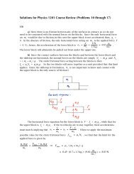
A passenger riding in the elevator car is subjected to two <strong>for</strong>ces, gravity and the<br />
normal <strong>for</strong>ce from the floor of the car. If this person is standing on a weight scale, the<br />
normal <strong>for</strong>ce N is applied to them <strong>through</strong> the body and mechanism of the scale; the<br />
scale displays the magnitude of this <strong>for</strong>ce N , which we read as that person’s “weight”.<br />
We have been referring to the upward direction along the axis of the elevator<br />
shaft as “positive”, so we write the net <strong>for</strong>ce on the passenger as N – Mg = Ma , with a<br />
being the acceleration of the elevator as seen by a stationary (inertial) observer. The<br />
normal <strong>for</strong>ce on the passenger, and thus the reading on the scale, is then<br />
N = M · ( g + a ) .<br />
For the purpose of calculation, we can express the scale reading in terms of the<br />
person’s weight Mg in ordinary Earth gravity as N = Mg (1 + a g<br />
) . For a passenger of<br />
ordinary Earth-gravity weight Mg = 800 N , during the acceleration phase <strong>for</strong> the<br />
elevator car, the scale would read N 1 = Mg (1 + a 1<br />
g<br />
) ≈ 800 N ⋅ (1 + 0.664 ) ≈ 854 N . In<br />
9.81<br />
other words, the passenger would “feel heavier” € than usual; in order to accelerate them<br />
upward, the elevator must apply a <strong>for</strong>ce larger than Mg against the person’s feet.<br />
Once the elevator car € reaches its “cruising phase”, it maintains a constant<br />
velocity v . Thus a = 0 , and the scale reads N 2<br />
= Mg ; the passenger experiences their<br />
usual weight, as if they were standing still on the Earth’s surface. During the car’s<br />
deceleration, the scale would read N 3 = Mg (1 + a 3<br />
g<br />
) ≈ 800 N ⋅ (1 + −0.415<br />
9.81 ) ≈ 766 N .<br />
The passenger “feels lighter” than usual, since the floor of the elevator car can apply a<br />
€
<strong>for</strong>ce less than Mg against the person’s feet, in order to provide an “upward<br />
deceleration”. (In effect, the elevator is actually permitting the passenger to fall under<br />
gravity, but subject to restraint, so that their acceleration is toward the Earth’s surface,<br />
but with a magnitude much less than g .)<br />
5) It will be helpful to establish first a two-dimensional coordinate system <strong>for</strong> the<br />
situation. If we call place the origin at the location of the adult ( x A<br />
= 0 , y A<br />
= 0 ) , the<br />
positive horizontal direction pointing toward the child, and the positive vertical<br />
direction pointing upward, then the child is located at ( x C<br />
= 20 cos 15º ≈ 19.32 m. ,<br />
y C<br />
= 20 sin 15º ≈ 5.18 m. ).<br />
In the first part of the problem, we wish to find how fast each person needs to<br />
throw the ball to reach the other person exactly. (We ignore the difference in the<br />
heights of adult and child, as far as how that affects where they each catch the ball.)<br />
The adult throws at a 30º angle to the 15º upward slope, so their throw starts at an<br />
angle of θ A<br />
= 45º to the horizontal. The child is throwing downhill at the same angle<br />
relative to the slope, so their throw starts at θ C<br />
= 15º to the horizontal. We will<br />
neglect air resistance, so the only <strong>for</strong>ce acting on the ball in flight is vertically<br />
downward-directed gravity.<br />
We will solve in parallel <strong>for</strong> the speeds at which adult and child each must throw<br />
the ball <strong>for</strong> a “perfect catch”:<br />
adult to child<br />
child to adult<br />
€<br />
€<br />
€<br />
x f = x C = x A + (v A cos θ A ) t + 1 2 ⋅ 0 ⋅ t 2<br />
x f = x A = x C − (v C cos θ C ) t + 1 2 ⋅ 0 ⋅ t 2<br />
⇒ 20 cos 15 o = 0 + (v A cos 45 o ) t ⇒ 0 = 20 cos 15 o − (v C cos 15 o ) t<br />
the sign of the velocity is reversed, since<br />
the child is throwing in the opposite x-direction<br />
€<br />
€<br />
20 cos 15o<br />
⇒ t =<br />
€<br />
v A<br />
cos 45 o ; ⇒<br />
20 cos 15o<br />
t =<br />
v C<br />
cos 15 o = 20<br />
v C<br />
;<br />
y f = y C = y A + (v A sin θ A ) t − 1 2 ⋅ g ⋅ t 2 y f = y A = y C + (v C sin θ C ) t − 1 2 ⋅ g ⋅ t 2<br />
€<br />
⇒ 20 sin 15 o = 0 + (v A sin 45 o ) t − 1 2 gt 2 €<br />
⇒ 0 = 20 sin 15 o + (v C sin 15 o ) t − 1 2 gt 2<br />
€<br />
€
We can substitute our result <strong>for</strong> t into these equations to find<br />
⎛⎛<br />
20 sin 15 o = (v A sin 45 o 20 cos 15<br />
)<br />
o ⎞⎞<br />
⎜⎜<br />
⎝⎝ v A<br />
cos 45 o ⎟⎟ − 1 ⎛⎛ 20 cos 15o ⎞⎞<br />
g⎜⎜<br />
⎠⎠ 2<br />
⎝⎝ v A cos 45 o ⎟⎟<br />
⎠⎠<br />
2<br />
0 = 20 sin 15 o + (v C sin 15 o ⎛⎛ 20 ⎞⎞<br />
) ⎜⎜ ⎟⎟ − 1 ⎝⎝ ⎠⎠ 2 g ⎛⎛ 20 ⎞⎞<br />
⎜⎜ ⎟⎟<br />
⎝⎝ ⎠⎠<br />
v C<br />
v C<br />
2<br />
€<br />
⇒ (20 cos 15 o tan 45 o − 20 sin 15 o 2<br />
) v A = 1 ⎛⎛ 20 cos 15o ⎞⎞<br />
g⎜⎜<br />
€<br />
2<br />
⎝⎝ cos 45 o ⎟⎟ ⇒ 2 ⋅ 20 sin 15 o 2<br />
⋅ v C<br />
⎠⎠<br />
multiplying <strong>through</strong> by the velocity squared, since it is not zero<br />
2<br />
= 1 2 ⋅ g ⋅ 202<br />
€<br />
⇒ v A<br />
2<br />
≈<br />
2<br />
9.81 ⋅ 20 2 ⋅ 0.966 2<br />
⎛⎛ 2 ⎞⎞<br />
2 ⋅ ⎜⎜ ⎟⎟ ⋅ 20 ⋅ (0.966 ⋅1 − 0.259)<br />
⎝⎝ 2 ⎠⎠<br />
€<br />
≈ 259.0 m.2<br />
sec. 2 <br />
⇒ v C<br />
2<br />
≈<br />
9.81 ⋅ 20 2<br />
2 ⋅ 2 ⋅ 20 ⋅ 0.259<br />
≈ 189.4<br />
m.2<br />
sec. 2 <br />
€<br />
⇒ v A ≈ 16.1 m.<br />
sec. <br />
€<br />
⇒ v C ≈ 13.8 m.<br />
sec.<br />
€<br />
For the second part of the problem, the physical arrangement <strong>for</strong> the two<br />
throwers is the same, but they will now both throw<br />
€<br />
the ball at v A<br />
= v<br />
C<br />
= 20 m./sec. ; we<br />
want to know where the ball would land in each case. The hillside has a slope of 15º, so<br />
we can idealize it by describing it by a line of slope m = tan 15º . Since the origin of our<br />
coordinate system is on the hillside, the equation <strong>for</strong> this line is y = (tan 15º) x . For<br />
each thrower, we need to work out the trajectory of the ball thrown by them and find<br />
where it intersects the line representing the hillside.<br />
We are not asked <strong>for</strong> the time the ball spends in flight, so we can take an<br />
approach in which we calculate the equation <strong>for</strong> the parabola of the ball’s trajectory <strong>for</strong><br />
each thrower, and then find where the parabola intersects the line of the hillside. The<br />
position equations now yield<br />
adult to child<br />
x = (20 cos 45 o ) t ⇒ t =<br />
x<br />
20 cos 45 o ; €<br />
x = 20 cos 15 o<br />
child to adult<br />
⇒<br />
− (20 cos 15 o ) t<br />
t = 1 −<br />
x<br />
20 cos 15 o ;<br />
€<br />
€<br />
€<br />
y = (20 sin 45 o ⎛⎛ x ⎞⎞<br />
) ⎜⎜<br />
⎝⎝ 20 cos 45 o ⎟⎟ − 1<br />
⎠⎠ 2 g<br />
⎛⎛ x ⎞⎞<br />
⎜⎜<br />
⎝⎝ 20 cos 45 o ⎟⎟<br />
⎠⎠<br />
⇒ y = (tan 45 o ) x −<br />
⎛⎛<br />
g<br />
⎞⎞<br />
⎜⎜<br />
⎝⎝ 2 ⋅ 20 2 cos 2 45 o ⎟⎟ x 2<br />
⎠⎠<br />
€<br />
2<br />
y = 20 sin 15 o + (20 sin 15 o ⎛⎛ x ⎞⎞<br />
) ⎜⎜ 1 −<br />
€<br />
⎝⎝ 20 cos 15 o ⎟⎟<br />
⎠⎠<br />
− 1 2<br />
2 g ⎛⎛<br />
1 − x ⎞⎞<br />
⎜⎜<br />
⎝⎝ 20 cos 15 o ⎟⎟<br />
⎠⎠<br />
€<br />
⇒ y = (2 ⋅ 20 sin 15 o − 1 2 g ) + ⎛⎛ g<br />
20 cos 15 o − tan 15 o ⎞⎞<br />
⎜⎜<br />
⎟⎟ x<br />
⎝⎝<br />
⎠⎠ <br />
€ ⎛⎛<br />
−<br />
g ⎞⎞<br />
⎜⎜<br />
⎝⎝ 2 ⋅ 20 2 cos 2 15 o ⎟⎟ x 2<br />
⎠⎠<br />
We set each of these functions <strong>for</strong> the parabolic trajectories € of each ball equal to the<br />
function <strong>for</strong> the line of the idealized hillside to find
€<br />
€<br />
⎛⎛<br />
(tan 15 o ) x = (tan 45 o ) x −<br />
g ⎞⎞<br />
⎜⎜<br />
⎝⎝ 2 ⋅ 20 2 cos 2 45 o ⎟⎟ x 2<br />
⎠⎠<br />
⇒ (tan 45 o − tan 15 o ) x −<br />
⎡⎡<br />
⇒ x ⋅ ⎢⎢ (tan 45 o − tan 15 o ) −<br />
⎣⎣<br />
⎛⎛ g ⎞⎞<br />
⎜⎜<br />
⎝⎝ 2 ⋅ 20 2 cos 2 45 o ⎟⎟ x 2 = 0<br />
⎠⎠<br />
€<br />
€<br />
€<br />
€<br />
⎛⎛<br />
g<br />
⎞⎞ ⎤⎤<br />
⎜⎜<br />
⎝⎝ 2 ⋅ 20 2 cos 2 45 o ⎟⎟ x⎥⎥ = 0<br />
⎠⎠ ⎦⎦<br />
(tan 15 o ) x = (2 ⋅ 20 sin 15 o − 1 2 g ) + ⎛⎛ g<br />
20 cos 15 o − tan 15 o ⎞⎞<br />
⎜⎜<br />
⎟⎟ x<br />
⎝⎝<br />
⎠⎠ <br />
⎛⎛<br />
−<br />
g ⎞⎞<br />
⎜⎜<br />
⎝⎝ 2 ⋅ 20 2 cos 2 15 o ⎟⎟ x 2<br />
⎠⎠<br />
⇒ (2 ⋅ 20 sin 15 o − 1 2 g ) + ⎛⎛ g<br />
20 cos 15 o − 2 ⋅ tan 15 o ⎞⎞<br />
⎜⎜<br />
⎟⎟ x<br />
⎝⎝<br />
⎠⎠<br />
⎛⎛<br />
−<br />
g<br />
⎞⎞<br />
⎜⎜<br />
⎝⎝ 2 ⋅ 20 2 cos 2 15 o ⎟⎟ x 2 = 0<br />
⎠⎠<br />
⇒ (2 ⋅ 20 ⋅ 0.259 − 1 2 ⋅ 9.81) + ⎛⎛ 9.81<br />
20 ⋅ 0.966 − 2 ⋅ 0.268 ⎞⎞<br />
⎜⎜<br />
⎟⎟ x<br />
€<br />
⎝⎝<br />
⎠⎠ <br />
⎛⎛<br />
−<br />
9.81 ⎞⎞<br />
⎜⎜<br />
⎟⎟ x 2 = 0<br />
⎝⎝ 2 ⋅ 400 ⋅ 0.933⎠⎠<br />
this requires the quadratic <strong>for</strong>mula<br />
in order to solve <strong>for</strong> x<br />
€<br />
⇒ x ≈ −0.02810 ± 0.028102 − 4 ⋅ 0.01314 ⋅ (−5.4478)<br />
2 ⋅ 0.01314<br />
€<br />
⇒ either x = 0 (which is x A<br />
) or ⇒ either x ≈ 19.29 m. (which is x C<br />
)<br />
x = (tan 45o − tan 15 o ) (2 ⋅ 20 2 cos 2 45 o )<br />
g<br />
€<br />
or x ≈ −21.43 m.<br />
€<br />
≈ (1 − 0.268) (2 ⋅ 400 ⋅ 1 2 )<br />
9.81<br />
≈ 29.85 m.<br />
(If we solved this problem by working out the time of flight, t , first, we find that<br />
t ≈ 2.11 seconds in both directions – perhaps a surprising result!)<br />
€<br />
The y-coordinate of the position where the ball will land on the hillside is<br />
y = (tan 15 o ) x ≈ 0.268 x ≈ 8.00 m.<br />
y ≈ 0.268 x ≈ − 5.74 m.<br />
The distance along the hillside from each thrower to the point where the ball lands is<br />
given by the “distance <strong>for</strong>mula”:<br />
€<br />
€<br />
d ≈ (29.85 − 0) 2 + (8.00 − 0) 2 ≈ 30.9 m.<br />
d ≈ (− 21.43 − 19.32) 2 + (− 5.74 − 5.18) 2 ≈ 42.2 m.<br />
€<br />
6) For the purpose of analyzing the <strong>for</strong>ces<br />
€<br />
and torques acting on the ladder, we will<br />
divide it into two halves, with the person standing on its left half. We will call the<br />
distance along the left leg, measuring upward from the floor, at which the person is<br />
located, x . The person’s weight is Mg and the weight of the ladder is mg . The<br />
reaction <strong>for</strong>ce with which the two legs of the ladder push against one another is R , the<br />
tension <strong>for</strong>ce in the support rod halfway up the ladder is T , and the normal <strong>for</strong>ces<br />
from the floor against the feet of the ladder are N L<br />
and N R<br />
.
Since this is intended to be a static configuration, the sum of the horizontal<br />
<strong>for</strong>ces, the sum of the vertical <strong>for</strong>ces, and the sum of the torques on the ladder are all<br />
zero. The net horizontal <strong>for</strong>ce on each leg is T – R = 0 ⇒ T = R . The net vertical<br />
<strong>for</strong>ce on the entire ladder is N L<br />
+ N R<br />
– Mg – mg = 0 ⇒ N L<br />
+ N R<br />
= Mg + mg . To<br />
analyze the torques on each leg, we will chose the reference point to be at the top of the<br />
ladder. For that choice, the reaction <strong>for</strong>ces R produce no torque, since the moment<br />
arm <strong>for</strong> those <strong>for</strong>ces is zero.
left leg --<br />
The sum of the torques on each leg must be zero, so we have:<br />
+(2.8 − x ) ⋅ Mg ⋅ sin θ + 1.4 ⋅ ( 1 2 mg ) ⋅ sin θ + 1.4 ⋅T ⋅ sin (θ + 90o ) − 2.8 ⋅ N L ⋅ sin (180 o − θ )<br />
€<br />
⇒ + (2.8 − x ) Mg sin θ + 0.7 mg sin θ + 1.4 T cos θ − 2.8 N L sin θ = 0<br />
sin( θ + 90º ) = cos θ sin( θ – 180º ) = sin θ<br />
right leg --<br />
€<br />
− 1.4 ⋅ ( 1 2 mg ) ⋅ sin θ − 1.4 ⋅T ⋅ sin (θ + 90o ) + 2.8 ⋅ N R ⋅ sin (180 o − θ )<br />
€<br />
€<br />
⇒ − 0.7 mg sin θ − 1.4 T cos θ + 2.8 N R sin θ = 0<br />
If we now use the measurements from the statement of the problem, along with<br />
the diagram in green, at the start of the solution, showing the right triangle representing<br />
a leg of the ladder, these equations become<br />
left leg --<br />
⎛⎛ 0.45⎞⎞<br />
⎛⎛<br />
(2.8 − 2.3) (900) ⎜⎜ ⎟⎟<br />
0.45⎞⎞<br />
+ 0.7 (12 ⋅ 9.81) ⎜⎜ ⎟⎟<br />
⎛⎛<br />
+ 1.4 T ⎜⎜ 1.326 ⎞⎞<br />
⎟⎟<br />
⎛⎛ 0.45⎞⎞<br />
− 2.8 N<br />
⎝⎝ 1.4 ⎠⎠<br />
⎝⎝ 1.4 ⎠⎠ ⎝⎝ 1.4 ⎠⎠<br />
L<br />
⎜⎜ ⎟⎟ = 0<br />
⎝⎝ 1.4 ⎠⎠<br />
<br />
⇒ 144.6 + 26.5 + 1.33T − 0.9 N L = 0 ⇒ 0.9 N L − 1.33T ≈ 171.1 N<br />
€<br />
right leg --<br />
€<br />
⎛⎛ 0.45⎞⎞<br />
− 0.7 (12 ⋅ 9.81) ⎜⎜ ⎟⎟<br />
⎛⎛<br />
− 1.4 T ⎜⎜ 1.326 ⎞⎞<br />
⎟⎟<br />
⎛⎛ 0.45⎞⎞<br />
+ 2.8 N<br />
⎝⎝ 1.4 ⎠⎠ ⎝⎝ 1.4 ⎠⎠<br />
R<br />
⎜⎜ ⎟⎟ = 0<br />
⎝⎝ 1.4 ⎠⎠<br />
⇒ − 26.5 − 1.33T + 0.9 N R = 0 ⇒ 0.9 N R − 1.33T ≈ 26.5 N<br />
€ At the moment, it appears that we have two equations with three unknowns. However,<br />
we have a way to eliminate two of these unknowns: if we add the equations <strong>for</strong> the left<br />
and right<br />
€<br />
legs together, and use the result from the vertical <strong>for</strong>ces equation, we obtain<br />
0.9 N L + 0.9 N R − 2.65T ≈ 197.6 N ⇒ 0.9 (N L + N R ) − 2.65T ≈ 197.6 N<br />
⇒ 0.9 (Mg + mg ) − 2.65T ≈ 197.6 N ⇒ 0.9 (900 N +117.7 N ) − 2.65T ≈ 197.6 N<br />
€<br />
€<br />
⇒ 2.65T ≈ 718.3 N ⇒ T ≈ 271 N ;<br />
the tension <strong>for</strong>ces at each end of the support rod are directed toward the center of the<br />
rod, so it is said to be “in compression”. We can now use the results from the torque<br />
€ equations to solve <strong>for</strong> the two normal <strong>for</strong>ces on the ladder’s feet:<br />
0.9 N L − 1.33 (271 N ) ≈ 171.1 N ⇒ N L ≈ 589 N ; <br />
0.9 N R − 1.33 (271 N ) ≈ 26.5 N ⇒ N R ≈ 429 N . <br />
€<br />
€
€<br />
For the second part of this problem, the physical situation is the same, but we<br />
will leave the location of the person using the ladder unspecified; hence, we will use the<br />
distance x , rather than the specific value 2.3 meters. The derivation will be as it was<br />
be<strong>for</strong>e, except that the torque equation <strong>for</strong> the left ladder leg is now<br />
(2.8 − x ) ⋅ 289.3 + 26.5 + 1.33T − 0.9 N L = 0<br />
⇒ 0.9 N L − 1.33T ≈ (836.5 − 289.3 x ) N .<br />
When we add this new equation to the equation <strong>for</strong> the right leg, we find<br />
0.9 N€<br />
L + 0.9 N R − 2.65T ≈ (836.5 − 289.3 x ) + 26.5 N = (863.0 − 289.3 x ) N<br />
⇒<br />
2.65T ≈ [ 0.9 (900 +117.7) − (863.0 − 289.3 x ) ] N<br />
€<br />
€<br />
€<br />
⇒<br />
T ≈<br />
(52.9 + 289.3 x ) N<br />
2.65<br />
= (20.0 + 109.2 x ) N .<br />
The sign of T is always positive, meaning that the support rod is always in<br />
compression, and increasingly so as the person climbs the ladder. If the substituted<br />
support rod will undergo a tension of T < 200 N be<strong>for</strong>e it crumples, the climber is<br />
limited to locations above the floor given by<br />
T ≈ (20.0 + 109.2 x ) N < 200 N ⇒ x <<br />
200 − 20.0<br />
109.2<br />
≈ 1.65 m. ,<br />
€<br />
as measured along the ladder leg upward from the foot, or about 59% of the way to the<br />
top of the ladder.<br />
7)<br />
a) This is a problem best analyzed in stages. The general principle that is<br />
followed here is that the center of mass of a stack of blocks must be supported by the<br />
block below it; otherwise the net torque due to gravity will cause the stack to tip over.<br />
Since every block is taken to have uni<strong>for</strong>m density, its center of mass is at the center of<br />
the block.
If we start by looking a single block, it must be placed so that no more than half<br />
its length overhangs the edge of the table; that is, the center of mass of the single block<br />
must be no further out than just at the edge of the table (which would make the block<br />
just marginally stable). The same would be true if this block were placed atop a second<br />
block: its center of mass must lie no further out than the edge of the lower block.<br />
Thus, the overhang distance of the first block is a 1<br />
= ½ L .
With a stack of two blocks, its center of mass is midway between the centers of<br />
mass of the invididual blocks, or one-quarter of the length of the bottom block from the<br />
edge under the first block. This stack can then only be placed as far over on the<br />
tabletop as to have this total center of mass at the table’s edge. So the maximum<br />
overhang of the second block is a 2<br />
= ¼ L .<br />
Once we get to a stack of three blocks, it’s a bit less obvious how to proceed, so<br />
we’ll look explicitly at the torque applied to the stack due to gravity. The amount of<br />
overhang <strong>for</strong> the third block, a 3<br />
, is unknown. This puts the center of mass <strong>for</strong> the<br />
upper two blocks beyond the edge of the table by a distance a<br />
3<br />
. Since the entire stack<br />
will pivot at that edge, the torque about that point due to the weight of the upper two<br />
blocks is τ upper<br />
= −2Mg · a 3<br />
sin 90º . The bottom block overhangs the table edge by a<br />
distance a 3<br />
, so its center of mass is ½L – a 3<br />
from the edge, and thus from the pivot<br />
point. The torque about that point due to the weight of the bottom block is then<br />
τ lower<br />
= +Mg · ( ½L – a 3<br />
) sin 90º . In order <strong>for</strong> the stack to remain static, then, the total<br />
torque on it must be<br />
Mg · ( ½L – a 3<br />
) − 2Mga 3<br />
= 0 ⇒ 3a 3<br />
= ½L ⇒<br />
a 3 = 1 6 L .<br />
Now that we have established a method of analysis, it’s straight<strong>for</strong>ward to extend it<br />
to a stack of four blocks. The torque due to gravity on the upper three blocks is<br />
τ upper<br />
= −3Mg · a 4<br />
sin 90º and that on the bottom block € is τ lower<br />
= +Mg · ( ½L – a 4<br />
) sin 90º ,<br />
so the sum of the torques <strong>for</strong> the stationary stack must be<br />
Mg · ( ½L – a 4<br />
) − 3Mga 4<br />
= 0 ⇒ 4a 4<br />
= ½L ⇒<br />
a 4 = 1 8 L .<br />
The total distance by which the leading edge of the top block in this stack<br />
extends beyond the edge of the table is then<br />
€<br />
d = a 1 + a 2 + a 3 + a 4 = 1 2 L + 1 4 L + 1 6 L + 1 8 L = 25<br />
24 L .<br />
€<br />
€<br />
This tells us that the length of the uppermost block in fact lies completely beyond the<br />
edge of the table!<br />
We could go on to find the result <strong>for</strong> a stack of any number of identical blocks<br />
arranged according to this rule. If we use n blocks, the total torque on the stack would<br />
be Mg · ( ½L – a n<br />
) − ( n – 1 )Mga n<br />
= 0 ⇒ na n<br />
= ½L ⇒ a n = 1<br />
2n L . So the<br />
amount by which the bottommost block extends over the edge of the table diminishes<br />
toward zero as the number of blocks in the stack increases. What about the distance that<br />
the top block extends past that edge The leading edge of the top block reaches past the<br />
€<br />
table’s edge by a distance d = a 1 + a 2 + a 3 + K + a n = ( 1 2 + 1 4 + 1 6 + K + 1<br />
2n) L .<br />
If we let the number of blocks increase without end, this total distance becomes<br />
d = 1 2 + 1 4 + 1 6 + K + 1<br />
2n + K<br />
. If you have learned<br />
( ) L = ( 1 1 + 1 2 + 1 3 + K + 1 n ) L + K<br />
2<br />
€<br />
about infinite series, you’ll recognize this unending sum in parentheses as the harmonic<br />
series, which also grows without limit. This means that we can make the top block of the<br />
stack reach beyond the end of the table by any distance we wish, provided that we use a<br />
large enough number of blocks!
) Because this arrangment of the four blocks is exactly symmetrical, its center<br />
of mass is at the exact geometrical center of the stack. (Note also that in this<br />
configuration, the center of mass is located where there is no actual mass.) This stack<br />
will then be in static balance (but will be only marginally stable) if the center of mass is<br />
just above the edge of the table. So the bottom block overhangs the table’s edge by<br />
exactly half the block’s length, hence b 2<br />
= ½L .<br />
We can just look at one of the blocks in the middle layer, again because of the<br />
stack’s symmetry. The <strong>for</strong>ces acting on this block are its own weight, Mg ; half the<br />
weight of the top block, ½Mg ; and the normal <strong>for</strong>ce upward from the bottom block, N .<br />
The weight <strong>for</strong>ce <strong>for</strong> a block acts effectively as if it were concentrated at its center of<br />
mass. The partial weight <strong>for</strong>ce from the upper block and the normal <strong>for</strong>ce from the<br />
bottom block will act effectively at points midway between the inner edge of the middle<br />
block and the end of the bottom block. The bottom block’s edge will serve as the pivot<br />
point <strong>for</strong> any tipping of the middle block.<br />
We will now look at the torques acting on the middle block. Its own weight <strong>for</strong>ce<br />
acts at a distance b 1<br />
– ½L from the pivot point, so that will produce a torque<br />
τ W<br />
= −Mg · ( b 1<br />
– ½L ) · sin 90º . The partial weight <strong>for</strong>ce from the top block acts at a<br />
distance ½ ( L – b 1<br />
) from the pivot point, which provides a torque of<br />
τ u<br />
= + ( ½ Mg ) · ½ ( L – b 1<br />
) · sin 90º . Since we want to find the arrangement <strong>for</strong> which<br />
these blocks just remain in static balance, we consider the situation where the middle<br />
block is just about to tip. In this case, the middle block is on the verge of breaking<br />
contact with the bottom block, at which point the normal <strong>for</strong>ce is N = 0 , thereby<br />
contributing no torque to the middle block. The net torque on the middle block in<br />
marginal static balance is then<br />
+ ( 1 2 Mg ) ⋅ 1 2 (L − b 1 ) − Mg ⋅ (b 1 − 1 2 L ) = 0 ⇒ 1 4 (L − b 1 ) = b 1 − 1 2 L<br />
⇒ b 1 + 1 4 b 1 = 1 2 L + 1 4 L ⇒ 5 4 b 1 = 3 4 L ⇒ b 1 = 3 5 L .<br />
€<br />
€
distance<br />
€<br />
The outer end of the middle block extends beyond the edge of the table by a<br />
h = b 1 + b 2 = 3 5 L + 1 2 L = 11<br />
10 L . So, as with part (a) of this problem, no<br />
portion of this block is actually over the surface of the table. (The situation <strong>for</strong> the<br />
middle blocks is an example of the concept of the architectural cantilever – albeit a<br />
marginally stable one here.)<br />
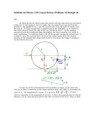
8)<br />
a) When the bicycle wheel comes into contact with the step, there are four <strong>for</strong>ces<br />
acting on it at that moment: its own weight, Mg ; the normal <strong>for</strong>ce upward from the<br />
ground, N ; the applied <strong>for</strong>ce, F ; and the reaction <strong>for</strong>ce from the point of contact with<br />
the step, R . If a large enough <strong>for</strong>ce is applied (and in the right place, as we shall see),<br />
the wheel will pivot about the edge of the step and lift up over it. For the minimal<br />
amount of <strong>for</strong>ce that would just make this happen, the wheel would be very nearly in<br />
static equilibrium. It would just begin to lift off the ground, causing the normal <strong>for</strong>ce N<br />
to drop to zero. The reaction <strong>for</strong>ce R acts at the contact point where the wheel is<br />
pivoting, so the moment arm along which it acts is zero, hence the torque it produces<br />
on the wheel is also zero.<br />
So only two of the a<strong>for</strong>ementioned <strong>for</strong>ces produce a torque on the wheel and<br />
only one of these is unknown, so the torque equation alone will suffice to determine the<br />
r<br />
"<br />
r<br />
" = r # F r<br />
= r F sin $<br />
value of F . The magnitude of a torque is given by ,<br />
which is equivalent to the magnitude of the <strong>for</strong>ce F times the perpendicular (or closest)<br />
distance, r sin θ , from the pivot point to the “line of action” of the <strong>for</strong>ce. Thus we find:<br />
!<br />
!
With the wheel just about to pivot around the step, the net torque is exactly zero, so the<br />
minimum applied <strong>for</strong>ce needed to lift the wheel over the step is given by<br />
%<br />
+ Mg " 2rh # h 2 # F " (r # h ) = 0 $ F = Mg<br />
'<br />
&<br />
2rh # h 2<br />
r # h<br />
(<br />
*<br />
)<br />
.<br />
The <strong>for</strong>m of this result appear reasonable. When there is no step ( h = 0 ) , the<br />
horizontal <strong>for</strong>ce required to lift the wheel becomes F = 0 . Somewhat less trivially, we<br />
! also find that it is impossible to lift the wheel, with a horizontally applied <strong>for</strong>ce, over a<br />
step with a height equal to or greater than the wheel’s radius ( F → ∞ as r → h ) .<br />
Notice that the moment of inertia, I , of the wheel does not enter into the<br />
calculation <strong>for</strong> F . This indicates that the applied <strong>for</strong>ce required would be the same if<br />
the wheel were a uni<strong>for</strong>m solid disk of the same mass and radius.<br />
b) There is more than one way to analyze the motion of an object rolling down<br />
an incline. We will use the most direct approach here.<br />
The <strong>for</strong>ces parallel to the incline are the parallel component of the weight <strong>for</strong>ce<br />
and the rolling friction <strong>for</strong>ce, f r<br />
. If we call the “downhill” direction positive, then we<br />
have Mg sin θ − f r<br />
= Ma ||<br />
. Rather than attempt to evaluate f r<br />
in terms of the normal<br />
<strong>for</strong>ce, N , it will be convenient to solve this equation <strong>for</strong> f r<br />
and apply that result; thus,<br />
f r<br />
= M ( g sin θ − a ||<br />
) . [ A ]
To analyze the torques on the rolling object, we will place the reference point at its<br />
center-of-mass. The weight <strong>for</strong>ce on the object then produces zero torque, since the moment<br />
arm <strong>for</strong> this <strong>for</strong>ce is zero. The normal <strong>for</strong>ce points directly toward the object’s center of<br />
mass along a radius (if the object is uni<strong>for</strong>mly dense, or has a density distribution which is<br />
radially symmetrical), so the torque it produces is τ N<br />
= R · N · sin 180º = 0 .<br />
Since the rolling friction <strong>for</strong>ce acts along the incline, it is perpendicular to the moment<br />
arm, which is on a radius of the object’s cross-section; the torque produced by this<br />
friction is then τ f<br />
= R · f r · sin 90º = f r<br />
R .<br />
For an object that rotates rigidly (all parts rotate at the same angular velocity),<br />
the magnitude of the net torque is τ net<br />
= I α . When the object is rolling, the angular<br />
acceleration is related to the linear acceleration by α = a . For each of the objects<br />
R<br />
we are considering, the moment of inertia about an axis parallel to its length and<br />
<strong>through</strong> its center-of-mass is given by I CM<br />
= C · MR 2 , where C = 1 <strong>for</strong> the tube (the<br />
same value as <strong>for</strong> a thin ring or hoop), C = ½ <strong>for</strong> the solid cylinder (same value as <strong>for</strong> a<br />
uni<strong>for</strong>m disk), and C = 2 <strong>for</strong> the uni<strong>for</strong>m<br />
€<br />
solid sphere. If we now combine the<br />
5<br />
equations related to torque with Equation A , we obtain<br />
€<br />
€<br />
€<br />
τ net = τ W + τ N + τ f = 0 + 0 + f r R = I CM α<br />
€<br />
⇒<br />
M (g sin θ − a || ) ⋅ R = C M R 2 ⎛⎛ a<br />
⋅ ||<br />
⎞⎞<br />
⎜⎜ ⎟⎟ = C M R a ||<br />
⎝⎝ R ⎠⎠<br />
⇒ g sin θ − a || = C a || ⇒ a || = g sin θ<br />
1 + C .<br />
€<br />
Notice that the mass, radius, and length of the rolling object don’t matter at all (at least<br />
in this idealization of rolling); only the distribution of mass about the center-of-mass<br />
affects the acceleration of the object going down the slope.<br />
€<br />
As all three of our objects are rolling downhill <strong>through</strong> the same distance, they<br />
will reach the bottom of the slope in order of decreasing linear acceleration. The<br />
uni<strong>for</strong>m solid sphere arrives there first, since its acceleration along the incline is<br />
g sin 22º<br />
a ||sph =<br />
1 + 2 = 5 m.<br />
g sin 22º ≈ 2.62<br />
7 sec. 2 . The uni<strong>for</strong>m solid cylinder will arrive<br />
5<br />
g sin 22º<br />
next, as its linear acceleration is a ||cyl =<br />
1 + 1 = 2 m.<br />
g sin 22º ≈ 2.45<br />
3 sec. 2 .<br />
2<br />
Coming in third and last is the thin-walled tube, which accelerates down the slope at<br />
g sin 22º<br />
a ||tube = = 1 m.<br />
g sin 22º ≈ 1.84<br />
1 + 1 2 sec.<br />
2 . Note that <strong>for</strong> a sliding block, <strong>for</strong> which<br />
€<br />
g sin 22º<br />
C is effectively zero, we have a ||block = = g sin 22º ≈ 3.67 m.<br />
1 + 0<br />
sec.<br />
2 , as expected.<br />
€
Now that we have worked out the linear accelerations down the ramp, we can use<br />
the kinematic equation <strong>for</strong> position to find the time each object requires to reach the<br />
bottom of the ramp. We will call the starting point at the top of the incline x 0<br />
= 0 ; all<br />
three objects start from rest ( v 0<br />
= 0 ) , so we can write<br />
x f = x 0 + v 0 t + 1 2 a || t 2 → L = 0 + 0 ⋅ t + 1 2 a || t 2<br />
€<br />
⎛⎛<br />
⇒ t = 2L ⎞⎞<br />
⎜⎜ ⎟⎟<br />
⎝⎝ ⎠⎠<br />
a ||<br />
1/ 2<br />
=<br />
⎛⎛ 2L ⎞⎞<br />
⎜⎜<br />
⎟⎟<br />
⎝⎝ g sin θ [1 + C ] ⎠⎠<br />
1/ 2<br />
=<br />
⎛⎛<br />
⎜⎜<br />
⎝⎝<br />
2 [1 + C ]L<br />
g sin θ<br />
⎞⎞<br />
⎟⎟<br />
⎠⎠<br />
1/ 2<br />
.<br />
For this situation in this Problem, this becomes<br />
€<br />
t =<br />
⎛⎛<br />
⎞⎞<br />
⎜⎜ 2 [1 + C ] ⋅ 1.5 m. ⎟⎟<br />
⎜⎜<br />
⎜⎜ ⋅ sin 22º<br />
⎟⎟<br />
⎟⎟<br />
⎝⎝ 2 ⎠⎠<br />
9.81 m.<br />
sec.<br />
1/ 2<br />
≈ 0.904 (1 + C ) 1/ 2 seconds .<br />
The three objects will thus reach the foot of the ramp after<br />
€ solid sphere:<br />
t ≈ 0.904 (1 + 2 5 )1/ 2 ≈ 1.070 seconds ,<br />
solid cylinder:<br />
€<br />
thin-walled tube:<br />
t ≈ 0.904 (1 + 1 2 )1/ 2 ≈ 1.107 seconds , and<br />
t ≈ 0.904 (1 + 1) 1/ 2 ≈ 1.278 seconds .<br />
€<br />
By contrast, the sliding block would reach the bottom in 0.904 seconds.<br />
9)<br />
€<br />
a) In this situation, due to the absence of friction, the two masses are in a<br />
marginally stable static equilibrium.<br />
We will call the downhill motion of m 1<br />
positive, which automatically makes the uphill<br />
motion of m 2<br />
positive in turn. The net <strong>for</strong>ce on m 1<br />
acting parallel to the incline it is on<br />
is m 1<br />
g sin 40º − T = 0 , while the net <strong>for</strong>ce on m 2<br />
acting parallel to its incline is
T − m 2<br />
g sin θ 2<br />
= 0 . When we solve each of these equations <strong>for</strong> the tension T in the<br />
connecting cord and then equate the results, we find m 1<br />
g sin 40º = T = m 2<br />
g sin θ 2<br />
.<br />
Since both of the masses of the blocks are known, we can solve <strong>for</strong> the angle θ 2<br />
that is<br />
required in order <strong>for</strong> this static equilibrium to exist:<br />
#<br />
sin " 2 = m &<br />
1<br />
% ( sin 40 o )<br />
$ '<br />
m 2<br />
# 1.8 kg. &<br />
% ( * 0.643 ) 0.386 + "<br />
$ 3.0 kg.<br />
2 ) 22.7 o .<br />
'<br />
!<br />
b) With the inclusion of friction, the static equilibrium of the two masses on<br />
their inclines becomes far more stable. In this portion of the Problem, the angle <strong>for</strong> the<br />
incline m 2<br />
rests upon is chosen to be θ 2<br />
= 32º . There are now two cases to consider<br />
<strong>for</strong> the limits of static equilibrium: one in which the mass m 1<br />
is just prevented from<br />
sliding downhill, the other in which it is just prevented from being drawn uphill.<br />
The <strong>for</strong>ces on each mass in the case where m 1<br />
resists sliding downhill are<br />
<strong>for</strong>ces perpendicular<br />
to incline<br />
<strong>for</strong>ces parallel to<br />
incline<br />
m 1<br />
m 2<br />
N 1 " m 1 g cos 40 o = m 1 a # = 0<br />
N 2 " m 2 g cos 32 o = m 2 a # = 0<br />
m 1 g sin 40 o " T " f s1max<br />
= m 1 a || = 0 T " m 2 g sin 32 o " f s 2max<br />
= m 2 a || = 0<br />
From the equations <strong>for</strong> the perpendicular (normal) <strong>for</strong>ces on the blocks, we obtain<br />
!<br />
!<br />
N 1<br />
= m 1<br />
g cos ! 40º and N 2<br />
= m 2<br />
g cos 32º . Since ! the limits of static friction on each<br />
block are<br />
, the equations <strong>for</strong> the <strong>for</strong>ces parallel to<br />
f s1max<br />
= µ s N 1 and f s 2max<br />
= µ s N 2<br />
each incline can be solved <strong>for</strong> the tension T in the cord, yielding<br />
m 1<br />
g sin 40º − µ s<br />
m 1<br />
g cos 40º = T = m 2<br />
g sin 32º + µ s<br />
m 2<br />
g cos 32º .<br />
!<br />
If we now solve this last equation <strong>for</strong> m 2<br />
, we have<br />
#<br />
m 2 = sin 40o " µ s cos 40 o & # 0.643 " 0.38 ) 0.766 &<br />
%<br />
sin 32 o + µ s cos 32 o ( ) m 1 * %<br />
( )1.8 kg. * 0.74 kg. ,<br />
$<br />
' $ 0.530 + 0.38 ) 0.848 '<br />
which is the smallest mass m 2<br />
may have in order to keep m 1<br />
from sliding downhill.<br />
!
If the block m 2<br />
is massive enough, it will instead apply enough tension in the<br />
cord to pull block m 1<br />
uphill. The limit of static friction on m 1<br />
in this direction is<br />
found by changing the equations <strong>for</strong> the <strong>for</strong>ces parallel to each incline to<br />
m 1 g sin 40 o " T ' + f s1<br />
= m and ;<br />
# max 1 a || = 0 T ' " m 2 g sin 32 o + f s # 2<br />
= m<br />
max 2 a || = 0<br />
the equations <strong>for</strong> the normal <strong>for</strong>ces are not affected. Repeating the rest of the<br />
calculations as we did be<strong>for</strong>e, we now have<br />
!<br />
#<br />
!<br />
m 2 = sin 40o + µ s cos 40 o &<br />
%<br />
$ sin 32 o " µ s cos 32 o ( ) m 1 *<br />
'<br />
# 0.643 + 0.38 ) 0.766 &<br />
%<br />
( )1.8 kg. * 8.09 kg. ,<br />
$ 0.530 " 0.38 ) 0.848 '<br />
the greatest mass this block may have without overcoming static friction and pulling the<br />
other block along after it.<br />
!<br />
c) We continue to use the Atwood machine described in part (b), but now with a<br />
mass m 2<br />
= 9.2 kg. We have seen that this will be more than sufficient mass to<br />
overcome static friction and set both blocks sliding along their inclines. The normal<br />
<strong>for</strong>ces acting on the blocks will still be as they were in part (b). However, with the<br />
blocks in motion, their accelerations will no longer be zero; with kinetic friction acting<br />
on the blocks, the equations <strong>for</strong> the <strong>for</strong>ces parallel to the inclines become<br />
and T '' " m 2 g sin 32 o + f k 2<br />
= m 2 a || ,<br />
m 1 g sin 40 o " T '' + f k 1<br />
= m 1 a ||<br />
with f k<br />
= µ k<br />
N . We now solve each equation <strong>for</strong> the new cord tension T’’ and equate<br />
the results to find<br />
!<br />
!<br />
m 1 g sin 40 o + µ k m 1 g cos 40 o " m 1 a || = T '' = m 2 g sin 32 o " µ k m 2 g cos 32 o + m 2 a ||<br />
!<br />
!<br />
" (m 1 + m 2 ) # a || = m 1 g sin 40 o + µ k m 1 g cos 40 o $ m 2 g sin 32 o + µ k m 2 g cos 32 o<br />
!<br />
$<br />
" a || = m 1 (sin 40o + µ k cos 40 o ) # m 2 (sin 32 o # µ k cos 32 o )'<br />
&<br />
) * g<br />
%<br />
m 1 + m 2<br />
(<br />
"<br />
% 1.8 kg. # (0.643 + 0.26 # 0.766) $ 9.2 kg. # (0.530 $ 0.26 # 0.848) (<br />
'<br />
* # (9.81 m.<br />
&<br />
1.8 + 9.2 kg.<br />
) sec. 2 )<br />
" # 0.121 g or #1.19 m. .<br />
sec. 2<br />
!<br />
The negative sign <strong>for</strong> this acceleration agrees with our expectation that m 1<br />
is being<br />
pulled uphill and it is m 2<br />
that is sliding downhill.<br />
!<br />
-- G.Ruffa<br />
original notes developed during 2006-08<br />
revised: August-September 2010, February 2011