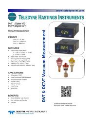
VT/CVT - Teledyne Hastings Instruments
VT/CVT - Teledyne Hastings Instruments
VT/CVT - Teledyne Hastings Instruments

You also want an ePaper? Increase the reach of your titles
YUMPU automatically turns print PDFs into web optimized ePapers that Google loves.
2.2. Cabinet Mount Vacuum Gauge<br />
<strong>Hastings</strong> cabinet models can be obtained with 2 - position or 5 - position tube switching<br />
functions that will allow the user to display pressure from one or more selected tubes. No<br />
special installation is necessary; simply connect the power cord and the gauge tube cables.<br />
Note: All of the gauge tube cables on either a 2-position or a 5-position unit<br />
must be equal in length. Mixing cable lengths on a particular unit will produce<br />
a calibration error due to the different resistances of the cables.<br />
2.3. External Cables and Wiring<br />
<strong>VT</strong> series units<br />
WARNING: To prevent shock hazard to personnel, always install protective<br />
cover before application of AC power or prior to placing instrument inservice.<br />
Connect the AC power cable, gauge tube cable, and analog output (analog output is only<br />
available on units configured from the factory with 0-1 VDC) as detailed in figure 2-4. The<br />
terminal block protective cover must be removed to access screw terminals.<br />
Terminal Function Description<br />
3 Gauge tube cable Heated T.C. (blk wire)<br />
4 AC power cable 115 VAC (blk wire)<br />
5 Gauge tube cable Heated T.C. (wht wire)<br />
6 Gauge tube cable Compensated T.C. (green wire)<br />
7 Analog output (1vdc) Negative analog output terminal<br />
8 Analog output (1vdc) Positive analog output terminal<br />
9 AC power cable Lo VAC (wht wire)<br />
10 AC power cable 230 VAC (blk wire)<br />
13 COM chassis ground<br />
14 COM AC power ground (green/yellow wire)<br />
WARNING:<br />
When 115 VAC is connected to the auto<br />
transformer, 230 VAC appears at the 230<br />
VAC terminal. The same occurs when you<br />
attach 230 VAC to the unit, 115 VAC appears<br />
at the 115 VAC terminal.<br />
Fig 2.4<br />
<strong>VT</strong> Series Terminal Block<br />
C<strong>VT</strong> series units<br />
Connect the AC power cable, gauge tube cable, control relay and analog output (analog<br />
output is optional on <strong>VT</strong> and standard on C<strong>VT</strong>) as detailed in figure 2-5. The terminal block<br />
protective cover must be removed to access screw terminals.<br />
146-112011_<strong>VT</strong>-C<strong>VT</strong> Page 7 of 14