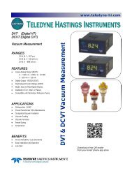
VT/CVT - Teledyne Hastings Instruments
VT/CVT - Teledyne Hastings Instruments
VT/CVT - Teledyne Hastings Instruments

Create successful ePaper yourself
Turn your PDF publications into a flip-book with our unique Google optimized e-Paper software.
3.0 Vacuum Gauge Operation<br />
3.1. Meter Mechanical Zero<br />
With the gauge in its normal operating position (AC power removed), check that the meter<br />
pointer covers the Dot at right-end of the dial face. If the Dot is not covered by the pointer,<br />
adjust screw at the front of the meter until the pointer covers the Dot.<br />
3.2. AC Input Power<br />
Connect the plug end of power cable into a single phase 115 or 230 V, 50/60 Hz power<br />
source (as per unit configuration). When replacing the power cords standard plug with a plug<br />
to match a particular system, care should be taken to connect the new plug in accordance with<br />
the terminal block connections listed in section 2.4 of this manual.<br />
3.3. Pressure Measurement<br />
Connect gauge tube cables octal socket onto the octal base of a gauge tube installed in<br />
vacuum system. The gauge will display the system pressure on the meter dial face. To check<br />
the accuracy of the gauge, perform the required operations as specified in section 3.5 of this<br />
manual.<br />
3.4. Controller Set Points (C<strong>VT</strong> units only)<br />
The C<strong>VT</strong> series vacuum controllers are provided with either single or double set points. On<br />
a single set point controller, the right-front panel knob allows the user to adjust or position the<br />
“RED” pointer on the dial face where a desired control function will occur.<br />
On the double set point controller, the left-front panel knob is added to allow the user to<br />
adjust or position a second “RED” pointer on the dial face where a desired control function<br />
will occur.<br />
On those controllers configured with two front panel knobs; the left knob controls the LO<br />
Set pressure (Relay K1), and the right knob controls the HI Set pressure (Relay K2).<br />
Control logic determines that a relay will (energize) when the indicated pressure is lower<br />
than the set-pressure, and de-energize when the indicated pressure is higher than the setpressure<br />
or if their is a loss of AC power to the unit.<br />
CAUTION:<br />
To avoid relay chatter, keep the lower set point above the ultimate system<br />
pressure<br />
3.5. Operation and Performance Check<br />
All <strong>Hastings</strong> vacuum gauges, controllers, and tubes have been carefully calibrated and<br />
checked at the factory before shipment. When a operational check or calibration is desired,<br />
refer to the procedure outlined in this section.<br />
The simplest and quickest way of checking the operation and performance of a gauge and/or<br />
gauge tube is to maintain a new or known-good gauge tube on hand for use as a Reference. To<br />
check operation, install both the Reference and suspect gauge tubes in a common vacuum<br />
146-112011_<strong>VT</strong>-C<strong>VT</strong> Page 10 of 14