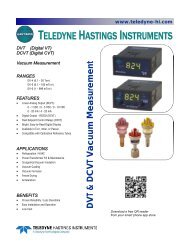
VT/CVT - Teledyne Hastings Instruments
VT/CVT - Teledyne Hastings Instruments
VT/CVT - Teledyne Hastings Instruments

You also want an ePaper? Increase the reach of your titles
YUMPU automatically turns print PDFs into web optimized ePapers that Google loves.
TELEDYNE<br />
HASTINGS<br />
INSTRUMENTS<br />
INSTRUCTION MANUAL<br />
<strong>VT</strong>/C<strong>VT</strong> SERIES<br />
VACUUM GAUGES<br />
and CONTROLLERS<br />
ISO 9001<br />
C E R T I F I E D
Manual Print History<br />
The print history shown below lists the printing dates of all revisions and addenda created for this manual.<br />
The revision level letter increases alphabetically as the manual undergoes subsequent updates. Addenda,<br />
which are released between revisions, contain important change information that the user should incorporate<br />
immediately into the manual. Addenda are numbered sequentially. When a new revision is created, all<br />
addenda associated with the previous revision of the manual are incorporated into the new revision of the<br />
manual. Each new revision includes a revised copy of this print history page.<br />
Revision A (Document Number 146-0497) ....................................................................... April 1997<br />
Revision B (Document Number 146-0999) ............................................................... September 1999<br />
Revision C (Document Number 146-0301) ..................................................................... March 2001<br />
Revision D (Document Number 146-0902) ............................................................... September 2002<br />
Revision E (Document Number 146-0805) .................................................................... August 2005<br />
Revision F (Document Number 146-0710).......................................................................... July 2010<br />
Revision F (Document Number 146-1111)................................................................ November 2011<br />
Visit www.teledyne-hi.com for WEEE disposal guidance.<br />
CAUTION:<br />
The instruments described in this manual are available with multiple pin-outs.<br />
Ensure that all electrical connections are correct.<br />
CAUTION:<br />
The instruments described in this manual are designed for INDOOR use only.<br />
CAUTION:<br />
The instruments described in this manual are designed for Class 2 installations<br />
in accordance with IAW/IPC standards<br />
<strong>Hastings</strong> <strong>Instruments</strong> reserves the right to change or modify the design of its equipment<br />
without any obligation to provide notification of change or intent to change.<br />
146-112011_<strong>VT</strong>-C<strong>VT</strong> Page 2 of 14
Table of Contents<br />
1.1. FEATURES ....................................................................................................................................................... 4<br />
1.2. SPECIFICATIONS ............................................................................................................................................. 4<br />
1.3. SAFETY ........................................................................................................................................................... 4<br />
1.4. ACCESSORIES .................................................................................................................................................. 5<br />
1.5. DV-6S: NEW DV-6 TUBE FOR SEVERE ENVIRONMENTS ............................................................................... 5<br />
1.6. CALIBRATION REFERENCE TUBES .................................................................................................................. 5<br />
2.0 INSTALLATION ............................................................................................................................................... 6<br />
2.1. PANEL MOUNT VACUUM GAUGE AND CONTROLLER ................................................................................... 6<br />
2.2. CABINET MOUNT VACUUM GAUGE ............................................................................................................... 7<br />
2.3. EXTERNAL CABLES AND WIRING ................................................................................................................... 7<br />
2.4. VACUUM GAUGE TUBE .................................................................................................................................. 9<br />
3.0 VACUUM GAUGE OPERATION .................................................................................................................. 10<br />
3.1. METER MECHANICAL ZERO ......................................................................................................................... 10<br />
3.2. AC INPUT POWER ......................................................................................................................................... 10<br />
3.3. PRESSURE MEASUREMENT ........................................................................................................................... 10<br />
3.4. CONTROLLER SET POINTS (C<strong>VT</strong> UNITS ONLY) .......................................................................................... 10<br />
3.5. OPERATION AND PERFORMANCE CHECK ..................................................................................................... 10<br />
3.6. GAUGE TUBE OPERATION ............................................................................................................................ 11<br />
3.7. ANALOG PRESSURE MEASUREMENT ............................................................................................................ 11<br />
3.8. CALIBRATION ............................................................................................................................................... 13<br />
3.8.1. CALIBRATION USING A VACUUM SYSTEM .............................................................................................. 13<br />
3.8.2. CALIBRATION USING A HASTINGS REFERENCE TUBE ............................................................................ 13<br />
4.0 WARRANTY .................................................................................................................................................... 14<br />
4.1. WARRANTY REPAIR POLICY ......................................................................................................................... 14<br />
4.2. NON-WARRANTY REPAIR POLICY ................................................................................................................ 14<br />
146-112011_<strong>VT</strong>-C<strong>VT</strong> Page 3 of 14
1.0 Installation<br />
This manual contains technical and general information relating to the installation,<br />
operation, and calibration of <strong>Hastings</strong> Vacuum Gauges, Controllers, and Gauge Tubes.<br />
For best performance, <strong>Hastings</strong> vacuum gauges should be operated with the appropriate<br />
<strong>Hastings</strong> gauge tube. Attempting to use a <strong>Hastings</strong> vacuum gauge with other manufacturer’s<br />
tubes may result in damage to both the gauge and tube.<br />
1.1. Features<br />
<strong>Hastings</strong> vacuum gauges and controllers are self-contained instruments that offer extreme<br />
versatility for most vacuum applications. The electronic design assures long life and minimal<br />
maintenance. Compact <strong>VT</strong> & C<strong>VT</strong> Models are ready for mounting onto a panel.<br />
<strong>Hastings</strong> vacuum gauges and controllers utilize <strong>Hastings</strong> rugged but sensitive gauge tubes<br />
which are designed specifically for each of the three available pressure ranges (consult <strong>Hastings</strong><br />
Ordering and Dimension guide).<br />
1.2. Specifications<br />
Pressure range:<br />
<strong>VT</strong>-4 series, C<strong>VT</strong>-14/24,................................................................................ 0-20 Torr or 0-20 mbar<br />
<strong>VT</strong>-5, C<strong>VT</strong>-15/25, ................................................................................. 0-100 mTorr or 0-0.1 mbar<br />
<strong>VT</strong>-6series, C<strong>VT</strong>-16/26, ......................................................................... 0-1000 mTorr or 0-1 mbar<br />
Input power ............................................................................................. 115 or 230 VAC, 50/60 Hz<br />
Output signal ....................................................................................... 0-1 VDC (analog, non-linear)<br />
Optional <strong>VT</strong> series<br />
Standard C<strong>VT</strong> series<br />
Control relays ..................................................................................... 5A @ 250 VAC (resistive load)<br />
5A @ 30 VDC (resistive load)<br />
Cables ..................................................................................................................... 6 ft (1.8 m) power<br />
8 ft (2.4 m) gauge tube<br />
Weight:<br />
Panel mount meters ..................................................................................... 1.78 lb (0.81 kg) w/cables<br />
Panels mount controller’s ............................................................................. 2.13 lb (0.97 kg) w/cables<br />
Cabinet models .............................................................................................. 4.25 lb (2.0 kg) w/cables<br />
1.3. Safety<br />
The following symbols and terms may be found on THI products and/or in THI manuals and indicate<br />
important information.<br />
When found on the device, this symbol indicates that the operator should refer to the manual for<br />
important instructions on the proper use of this device. When found in a manual, this symbol<br />
indicates that the reader should understand the implications contained in the text before operating<br />
the device.<br />
The WARNING label indicates important information that should be heeded for safe and proper<br />
performance of the device.<br />
146-112011_<strong>VT</strong>-C<strong>VT</strong> Page 4 of 14
The label, CAUTION, is used to indicate that damage to the power supply or equipment connected to it,<br />
could occur if directions are not followed. Warranty could be invalidated if the instructions in this manual<br />
are not followed.<br />
1.4. Accessories<br />
Extension Cables for <strong>VT</strong> Series<br />
THI offers a complete line of system attachments that<br />
55-3 OM-8-OFV 8 Ft Extension Cable<br />
permit easy maintenance for contaminated operations.<br />
55-22 OM-12-OFV 12 Ft Extension Cable<br />
Gauge tubes are offered with various system fittings to<br />
match almost any system requirement. Additionally, THI’s 65-53 OM-25-OFV 25 Ft Extension Cable<br />
complete line of quick disconnect attachments allows 65-102 OM-50-OFV 50 Ft Extension Cable<br />
customers to install these special fittings and easily replace<br />
55-142 OM-100-OFV 100 Ft Extension Cable<br />
sensors without vacuum sealant or Teflon® tape. For<br />
particularly dirty systems, <strong>Hastings</strong> offers a<br />
particle dropout trap containing a series of Vacuum Gauge Tubes 1000 mTorr Range<br />
nine separate baffles which prevent solid<br />
contaminants from having a direct path to<br />
the sensor’s thermopile.<br />
Stock # Model # Description<br />
1.5. DV-6S: New DV-6 tube For<br />
Severe Environments<br />
<strong>Hastings</strong> <strong>Instruments</strong> has developed a new<br />
gauge tube, the DV-6S, which is specifically<br />
designed for outdoor use on cryogenic tanks<br />
including railcar and tanker truck<br />
applications. In addition to the DAVC, the<br />
gauge tube is compatible with the hand-held<br />
HPM-4/6 and the analog <strong>VT</strong>-6.<br />
The DV-6S is supplied with a protective<br />
cap. The o-ring-sealed cap protects the<br />
gauge tube pins from moisture thus<br />
significantly reducing corrosion. A metal<br />
lanyard prevents cap loss. The tube is<br />
provided with a standard 1/8” NPT fitting;<br />
however special fitting requests can often be<br />
met.<br />
1.6. Calibration Reference Tubes<br />
55-38 DV-6M 1/8” NPT Standard (Yellow base)<br />
55-38R DV-6R 1/8” Ruggedized<br />
55-38RS DV-6 1/8” NPT Rohs Rugged<br />
55-38S DV-6S 1/8” NPT Rugged/Vibration<br />
55-251 DV-6-KF-16 KF-16 TM<br />
55-267 DV-6-KF-25 KF-25 TM<br />
55-283 DV-6-VCR VCR TM<br />
55-38R-CF DV-6R-CF Mini Conflat TM<br />
Vacuum Gauge Tubes 100 mTorr Range<br />
55-19 DV-5M 1/8” NPT (Red Base)<br />
55-230 DV-5M -VCR VCR TM<br />
Vacuum Gauge Tubes 20Torr Range<br />
55-19 DV-4D 1/8” NPT (Purple Base)<br />
55-19R DV-4R 1/8” NPT Ruggedized<br />
55-258 DV-4D-KF-16 KF-16 TM<br />
55-266 DV-4D-KF-25 KF-25 TM<br />
THI Reference Tubes employ the same<br />
metal thermopiles used in all THI Vacuum<br />
55-227 DV-4D-VCR VCR TM<br />
Gauge Tubes. The thermopile is sealed in a<br />
glass capsule that has been evacuated, baked,<br />
Reference Tubes for use with <strong>VT</strong>/C<strong>VT</strong><br />
out-gassed, and then aged to ensure longterm<br />
stability. The sealed capsule is then<br />
housed in a protective metal shell to provide<br />
a rugged, trouble-free assembly.<br />
55-104<br />
55-101<br />
55-103<br />
DB-20<br />
DB-16D<br />
DB-18<br />
Ref Tube (DV-6) for DV-6 Calibration<br />
Ref Tube (DV-4D) for DV-4 Calibration<br />
Ref Tube (DV-5) for DV-5 Calibration<br />
Once assembled, the reference gauge tube is accurately calibrated to precisely simulate a gauge tube at a<br />
given operating pressure. It provides quick and easy instrument re-calibration by merely plugging the<br />
instrument and adjusting the calibration potentiometer until the display reads the exact pressure noted on<br />
the reference tube.<br />
146-112011_<strong>VT</strong>-C<strong>VT</strong> Page 5 of 14
2.0 Installation<br />
2.1. Panel Mount Vacuum Gauge and Controller<br />
Refer to figures 2.1 and 2.2 for outline dimensions of <strong>Hastings</strong> <strong>VT</strong> and C<strong>VT</strong> series units, to<br />
be used when considering mounting locations. Use dimensional drawing (figure 2.3) to cut-out<br />
and drill the gauge/controller mounting panel. Install gauge or controller onto panel using<br />
hardware supplied with your unit.<br />
MODEL<br />
SERIAL<br />
Fig 2.1<br />
<strong>VT</strong> Series<br />
mTorr<br />
Fig 2.2<br />
C<strong>VT</strong> Series<br />
Mounting Dimensions<br />
146-112011_<strong>VT</strong>-C<strong>VT</strong> Page 6 of 14
2.2. Cabinet Mount Vacuum Gauge<br />
<strong>Hastings</strong> cabinet models can be obtained with 2 - position or 5 - position tube switching<br />
functions that will allow the user to display pressure from one or more selected tubes. No<br />
special installation is necessary; simply connect the power cord and the gauge tube cables.<br />
Note: All of the gauge tube cables on either a 2-position or a 5-position unit<br />
must be equal in length. Mixing cable lengths on a particular unit will produce<br />
a calibration error due to the different resistances of the cables.<br />
2.3. External Cables and Wiring<br />
<strong>VT</strong> series units<br />
WARNING: To prevent shock hazard to personnel, always install protective<br />
cover before application of AC power or prior to placing instrument inservice.<br />
Connect the AC power cable, gauge tube cable, and analog output (analog output is only<br />
available on units configured from the factory with 0-1 VDC) as detailed in figure 2-4. The<br />
terminal block protective cover must be removed to access screw terminals.<br />
Terminal Function Description<br />
3 Gauge tube cable Heated T.C. (blk wire)<br />
4 AC power cable 115 VAC (blk wire)<br />
5 Gauge tube cable Heated T.C. (wht wire)<br />
6 Gauge tube cable Compensated T.C. (green wire)<br />
7 Analog output (1vdc) Negative analog output terminal<br />
8 Analog output (1vdc) Positive analog output terminal<br />
9 AC power cable Lo VAC (wht wire)<br />
10 AC power cable 230 VAC (blk wire)<br />
13 COM chassis ground<br />
14 COM AC power ground (green/yellow wire)<br />
WARNING:<br />
When 115 VAC is connected to the auto<br />
transformer, 230 VAC appears at the 230<br />
VAC terminal. The same occurs when you<br />
attach 230 VAC to the unit, 115 VAC appears<br />
at the 115 VAC terminal.<br />
Fig 2.4<br />
<strong>VT</strong> Series Terminal Block<br />
C<strong>VT</strong> series units<br />
Connect the AC power cable, gauge tube cable, control relay and analog output (analog<br />
output is optional on <strong>VT</strong> and standard on C<strong>VT</strong>) as detailed in figure 2-5. The terminal block<br />
protective cover must be removed to access screw terminals.<br />
146-112011_<strong>VT</strong>-C<strong>VT</strong> Page 7 of 14
TERMINAL FUNCTION DESCRIPTION<br />
1 Lo set relay (Normally Closed) relay contact<br />
2 Lo set relay (Normally Open) relay contact<br />
3 Gauge tube cable Heated T.C. (blk wire)<br />
4 AC power cable 115 VAC (blk wire)<br />
5 Gauge tube cable Heated T.C. (wht wire)<br />
6 Gauge tube cable Compensated T.C. (green wire)<br />
7 Analog output (1vdc) negative analog output terminal<br />
8 Analog output (1vdc) positive analog output terminal<br />
9 AC power cable Lo VAC (wht WIRE)<br />
10 AC power cable 230 VAC (blk WIRE)<br />
11 Spare no connection<br />
12 Lo set relay (COM) relay contact<br />
13 COM chassis ground<br />
14 COM AC power ground (green/yellow wire)<br />
15 Hi set relay (Normally Closed) relay contact<br />
16 Hi set relay (Normally Open) relay contact<br />
17 Hi set relay (COM) relay contact<br />
Fig 2.5<br />
C<strong>VT</strong> Series<br />
Terminal Block<br />
WARNING:<br />
When 115 VAC is connected to the auto transformer, 230 VAC appears at the<br />
230 VAC terminal. The same occurs when you attach 230 VAC to the unit, 115<br />
VAC appears at the 115 VAC terminal.<br />
146-112011_<strong>VT</strong>-C<strong>VT</strong> Page 8 of 14
2.4. Vacuum Gauge Tube<br />
All <strong>Hastings</strong> gauge tubes are shipped with a protective cap or cover at the evacuation port to<br />
reduce contamination and prevent physical damage to the internal thermopile elements. Once<br />
the protective cap or cover is removed, a tube can be installed in any convenient position in the<br />
vacuum system without adversely affecting calibration or performance. The recommended<br />
orientation is with the tube vertical and its stem down. This will aide in preventing condensable<br />
materials from remaining in the gauge tube.<br />
<strong>Hastings</strong> instruments also offer a wide variety of installation accessories for use with your<br />
vacuum gauge tube. Please consult the <strong>Hastings</strong> Ordering and Dimension Guide or contact<br />
your factory representative for information on these products.<br />
WARNING: Compression seal fittings “Quick-Connects” are not for use in<br />
systems where the tube can be pressurized above atmosphere.<br />
146-112011_<strong>VT</strong>-C<strong>VT</strong> Page 9 of 14
3.0 Vacuum Gauge Operation<br />
3.1. Meter Mechanical Zero<br />
With the gauge in its normal operating position (AC power removed), check that the meter<br />
pointer covers the Dot at right-end of the dial face. If the Dot is not covered by the pointer,<br />
adjust screw at the front of the meter until the pointer covers the Dot.<br />
3.2. AC Input Power<br />
Connect the plug end of power cable into a single phase 115 or 230 V, 50/60 Hz power<br />
source (as per unit configuration). When replacing the power cords standard plug with a plug<br />
to match a particular system, care should be taken to connect the new plug in accordance with<br />
the terminal block connections listed in section 2.4 of this manual.<br />
3.3. Pressure Measurement<br />
Connect gauge tube cables octal socket onto the octal base of a gauge tube installed in<br />
vacuum system. The gauge will display the system pressure on the meter dial face. To check<br />
the accuracy of the gauge, perform the required operations as specified in section 3.5 of this<br />
manual.<br />
3.4. Controller Set Points (C<strong>VT</strong> units only)<br />
The C<strong>VT</strong> series vacuum controllers are provided with either single or double set points. On<br />
a single set point controller, the right-front panel knob allows the user to adjust or position the<br />
“RED” pointer on the dial face where a desired control function will occur.<br />
On the double set point controller, the left-front panel knob is added to allow the user to<br />
adjust or position a second “RED” pointer on the dial face where a desired control function<br />
will occur.<br />
On those controllers configured with two front panel knobs; the left knob controls the LO<br />
Set pressure (Relay K1), and the right knob controls the HI Set pressure (Relay K2).<br />
Control logic determines that a relay will (energize) when the indicated pressure is lower<br />
than the set-pressure, and de-energize when the indicated pressure is higher than the setpressure<br />
or if their is a loss of AC power to the unit.<br />
CAUTION:<br />
To avoid relay chatter, keep the lower set point above the ultimate system<br />
pressure<br />
3.5. Operation and Performance Check<br />
All <strong>Hastings</strong> vacuum gauges, controllers, and tubes have been carefully calibrated and<br />
checked at the factory before shipment. When a operational check or calibration is desired,<br />
refer to the procedure outlined in this section.<br />
The simplest and quickest way of checking the operation and performance of a gauge and/or<br />
gauge tube is to maintain a new or known-good gauge tube on hand for use as a Reference. To<br />
check operation, install both the Reference and suspect gauge tubes in a common vacuum<br />
146-112011_<strong>VT</strong>-C<strong>VT</strong> Page 10 of 14
system (locate the gauge tubes as close as possible to each other), then evacuate the system<br />
until a stable base pressure is obtained. Alternately connect the vacuum gauge to each gauge<br />
tube and record its pressure readings. If the gauge tube-under-test produces a higher pressure<br />
reading than the Reference gauge tube, this indicates a calibration shift and is usually the result<br />
of contamination (particulate, oil, or other chemical deposits). You can try to restore<br />
calibration of the contaminated gauge tube by cleaning it internally with an appropriate solvent<br />
such as high-purity isopropyl alcohol (flood interior cavity of gauge tube gently with solvent<br />
and allow it to stand and soak for about 15 to 30-minutes). Drain the contaminated solvent<br />
and let gauge tube dry in ambient air until all of the cleaning solvent has evaporated. To<br />
prevent mechanical damage to the thermopile elements, do not use forced air to dry the gauge<br />
tube. Gauge tubes that remain out of<br />
calibration after cleaning should be replaced.<br />
3.6. Gauge Tube Operation<br />
Operation of the <strong>Hastings</strong> gauge tube is<br />
based on a low voltage AC bridge that heats a<br />
noble metal thermopile. A change in pressure<br />
in the gauge tube changes the molecular<br />
collision rate and therefore the thermal<br />
conduction of the gas or gas mixture<br />
surrounding the thermopile. This results in a<br />
temperature shift in the AC heated<br />
thermocouples A and B (Fig. 3.1). The<br />
resultant temperature shift causes a change in<br />
the DC output from couples A and B<br />
inversely with pressure changes. The DC thermocouple C (when installed)<br />
is in series with the circuit load. Thermocouple C provides compensation<br />
for transient changes in ambient temperature.<br />
Fig 3.1<br />
3.7. Analog Pressure Measurement<br />
An analog Signal Output line, pin 8, supplies a 0 to 1 VDC signal corresponding to the<br />
output range of the selected tube. This signal should be measured with respect to the analog<br />
Signal Common line, pin 7. See the INSTALLATION section for a diagram showing the<br />
Analog Signal pin out.<br />
This signal is equal to an amplified tube<br />
millivolt signal. This signal will NOT be<br />
linearly proportional to the indicated<br />
pressure. 1 volt will correspond to a system<br />
pressure that is at least 1 order of magnitude<br />
less than the minimum detectable pressure.<br />
Increasing pressure will be indicated by a<br />
Parameters DV6 DV4 DV5<br />
a -1623.22 -5.10184 -0.25948<br />
b -58.0442 -6.91233 -42.23869<br />
c -11732.2 -4.4943 -2.92598<br />
d -130.397 -6.30995 -256.9951<br />
e 13338.17 9.563177 3.18016<br />
decreasing voltage. The minimum detectable pressure is 0.2 millitorr for DV-5, 1 millitorr for<br />
DV-6 and 20 millitorr for DV-4.<br />
The voltage signal can be mapped to a pressure value by using the following equation.<br />
Where:<br />
a + cV + eV<br />
P =<br />
1+<br />
bV + dV<br />
2<br />
2<br />
V = Voltage<br />
P = pressure in Torr for DV4 & DV5 versions and millitorr for DV6<br />
See Chart below<br />
146-112011_<strong>VT</strong>-C<strong>VT</strong> Page 11 of 14
100<br />
Analog Output vs Pressure<br />
DV6<br />
10<br />
DV4<br />
DV5<br />
1<br />
Pressure (Torr)<br />
0.1<br />
0.01<br />
0.001<br />
0.0001<br />
0 0.2 0.4 0.6 0.8 1 1.2<br />
Voltage<br />
146-112011_<strong>VT</strong>-C<strong>VT</strong> Page 12 of 14
3.8. Calibration<br />
Using a vacuum system to calibrate a gauge or gauge/tube combination will result in a more<br />
accurate pressure measurement. For instances where this is not possible, calibrating the gauge<br />
using a <strong>Hastings</strong> reference tube provides the best alternative.<br />
NOTE: For cabinet models, the top-cover must be removed to access the CAL control.<br />
3.8.1. Calibration Using A Vacuum System<br />
Install the gauge tube in a vacuum system (gauge connected to AC power and stabilized),<br />
then evacuate to a pressure one decade or more below the gauge dial face resolution. Connect<br />
the gauge to tube and wait until the displayed pressure is stable.<br />
NOTE: When using a DV-4 type gauge tube, system pressure must be less than 1.0 x10 -2 Torr.<br />
When using DV-5 or DV-6 type gauge tubes, system pressure must be less than 1.0 x 10 -5 Torr.<br />
Adjust the gauge CAL. adjustment (figure 3.2) until the meter pointer indicates zero-left on<br />
the dial face.<br />
3.8.2. Calibration Using A <strong>Hastings</strong> Reference Tube<br />
Connect a <strong>Hastings</strong> reference tube to a stabilized vacuum gauge. Wait until the displayed pressure is<br />
stable.<br />
NOTE: The following table specifies the <strong>Hastings</strong> reference tube to be used in the calibration of a<br />
gauge based upon the type of gauge tube being used:<br />
Reference tube<br />
DB-16D<br />
DB-18<br />
DB-20<br />
Gauge tube<br />
DV-4<br />
DV-5<br />
DV-6<br />
Adjust the gauge CAL control (figure 3.2) until the meter pointer indicates the pressure<br />
specified on the decal of the reference tube in use.<br />
Fig 3.2<br />
calibration points<br />
146-112011_<strong>VT</strong>-C<strong>VT</strong> Page 13 of 14
4.0 Warranty<br />
4.1. Warranty Repair Policy<br />
<strong>Hastings</strong> <strong>Instruments</strong> warrants this product for a period of one year from the date of<br />
shipment to be free from defects in material and workmanship. This warranty does not apply to<br />
defects or failures resulting from unauthorized modification, misuse or mishandling of the<br />
product. This warranty does not apply to batteries or other expendable parts, nor to damage<br />
caused by leaking batteries or any similar occurrence. This warranty does not apply to any<br />
instrument which has had a tamper seal removed or broken.<br />
This warranty is in lieu of all other warranties, expressed or implied, including any implied<br />
warranty as to fitness for a particular use. <strong>Hastings</strong> <strong>Instruments</strong> shall not be liable for any<br />
indirect or consequential damages.<br />
<strong>Hastings</strong> <strong>Instruments</strong>, will, at its option, repair, replace or refund the selling price of the<br />
product if <strong>Hastings</strong> <strong>Instruments</strong> determines, in good faith, that it is defective in materials or<br />
workmanship during the warranty period. Defective instruments should be returned to<br />
<strong>Hastings</strong> <strong>Instruments</strong>, shipment prepaid, together with a written statement of the problem<br />
and a Return Material Authorization (RMA) number. Please consult the factory for your RMA<br />
number before returning any product for repair. Collect freight will not be accepted.<br />
4.2. Non-Warranty Repair Policy<br />
Any product returned for a non-warranty repair must be accompanied by a purchase order,<br />
RMA form and a written description of the problem with the instrument. If the repair cost is<br />
higher, you will be contacted for authorization before we proceed with any repairs. If you then<br />
choose not to have the product repaired, a minimum will be charged to cover the processing<br />
and inspection. Please consult the factory for your RMA number before returning any product<br />
repair.<br />
TELEDYNE HASTINGS INSTRUMENTS<br />
804 NEWCOMBE AVENUE<br />
HAMPTON, VIRGINIA 23669 U.S.A.<br />
ATTENTION: REPAIR DEPARTMENT<br />
TELEPHONE (757) 723-6531<br />
1-800-950-2468<br />
FAX (757) 723-3925<br />
E MAIL<br />
mailto:hastings_instruments@teledyne.com<br />
INTERNET ADDRESS http://www.teledyne-hi.com<br />
Repair Forms may be obtained from the “Information Request” section of the <strong>Hastings</strong><br />
<strong>Instruments</strong><br />
146-112011_<strong>VT</strong>-C<strong>VT</strong> Page 14 of 14