Military Communications and Information Technology: A Trusted ...
Military Communications and Information Technology: A Trusted ... Military Communications and Information Technology: A Trusted ...
500 Military Communications and Information Technology... j 2 i t i j ft x t Ae Ae i i (1) i i i where: A i – amplitude of i – harmonic, f i – frequency of i – harmonic, φ i – starting phase of i – harmonic. In order to ensure the imperceptibility of the OFDM signal in the background of the audio signal, the amplitude value of each harmonic is determined by the corresponding LT min level. Fig. 3 presents the amplitude and phase spectrum of the OFDM signal. The values of the 0 rad/s angle phase are assigned to spectral levels with indexes of (1,4,7,8,11,14). Amplitudes of lines in fig. 3 are marked in red. Figure 3. Amplitude and phase spectrum of the OFDM signal Of 14 harmonics presented in fig. 3, 6 harmonics (marked in red) are utilized on the receiver side to determine the correction values of the angle phase drift. The necessity to determine the correction of the angle phase drift arises from the differing stability of clocks tacking the sampling circuits in the transmitter and the receiver. The remaining 8 harmonics (marked in blue) are utilized on the receiver side to reproduce the time synchronization. The harmonics used for determining the correction of the angle phase drift are assigned the angle phase value of 0 [rad/s], whereas the lines responsible for time synchronization are assigned the angle phase values of π/2 and –π/2. Furthermore, in order to improve the efficiency of watermark signal extraction, the embedder utilizes the differential coding mechanism [9]. The principle of the mechanism is that the coding of the same bit takes place in two adjacent frames (subframes) of the host signal, but using opposing patterns. The manner of pattern selection is provided in fig. 4. Assuming that the subframes contain 512 samples each,
Chapter 4: Information Assurance & Cyber Defence 501 the coding of a single bit will require 1024 signal samples which, given the sampling frequency of f s = 44 100 Hz, allows for creating a hidden transmission channel with the bitrate of 43 bps. In particular the data bit rate of the proposed algorithm: where: f s – sampling frequency, N – number of samples. f s bit rate [ bps] (2) N B. Watermark extractor – principle of operation The schematic of the watermark extractor is provided in Fig. 5. The extraction mechanism of binary signature belongs to the class of algorithms using the socalled blind decoding method, i.e. the receiver side does not require the host signal. The watermarked signal first encounters the angle phase drift scanner, which corrects the angle phase drift for the pilot samples (cf. red-marked lines in fig. 3). The angle phase drift is caused by differing stability of clocks tacking the sampling circuits in the transmitter and the receiver of the watermark (e.g. in the case of a watermark signal transmission in a VHF circuit). As previously mentioned, the watermark embedder has 6 pilot spectral lines with the assigned angle phase value of 0[rad/s]. The same angle phase value is expected on the receiver side. The angle phase scanner allows for reproducing the drift value of the angle phase by analyzing the values of the virtual line module, which is the sum of pilot line modules. In the proposed algorithm the individual increment of the angle phase Δφ 1 is Δφ 1 = 0.000767 [rad/s]. Figure 4. Pattern selection method for differential coding
- Page 449 and 450: Chapter 4: Information Assurance &
- Page 451 and 452: Chapter 4: Information Assurance &
- Page 453 and 454: Chapter 4: Information Assurance &
- Page 455 and 456: Generation of Nonlinear Feedback Sh
- Page 457 and 458: Chapter 4: Information Assurance &
- Page 459 and 460: Chapter 4: Information Assurance &
- Page 461 and 462: Chapter 4: Information Assurance &
- Page 463: Chapter 4: Information Assurance &
- Page 466 and 467: 466 Military Communications and Inf
- Page 468 and 469: 468 Military Communications and Inf
- Page 470 and 471: 470 Military Communications and Inf
- Page 472 and 473: 472 Military Communications and Inf
- Page 474 and 475: 474 Military Communications and Inf
- Page 476 and 477: 476 Military Communications and Inf
- Page 478 and 479: 478 Military Communications and Inf
- Page 480 and 481: 480 Military Communications and Inf
- Page 482 and 483: 482 Military Communications and Inf
- Page 485 and 486: Modern Usage of “Old” One-Time
- Page 487 and 488: Chapter 4: Information Assurance &
- Page 489 and 490: Chapter 4: Information Assurance &
- Page 491 and 492: Chapter 4: Information Assurance &
- Page 493 and 494: Chapter 4: Information Assurance &
- Page 495: Chapter 4: Information Assurance &
- Page 498 and 499: 498 Military Communications and Inf
- Page 502 and 503: 502 Military Communications and Inf
- Page 504 and 505: 504 Military Communications and Inf
- Page 506 and 507: 506 Military Communications and Inf
- Page 508 and 509: 508 Military Communications and Inf
- Page 511 and 512: A Abut Fatih 161 Akcaoglu Ismail 11
500 <strong>Military</strong> <strong>Communications</strong> <strong>and</strong> <strong>Information</strong> <strong>Technology</strong>...<br />
j 2<br />
<br />
i t i j ft<br />
x t Ae Ae<br />
i <br />
i<br />
(1)<br />
i i i<br />
where:<br />
A i – amplitude of i – harmonic,<br />
f i – frequency of i – harmonic,<br />
φ i – starting phase of i – harmonic.<br />
In order to ensure the imperceptibility of the OFDM signal in the background<br />
of the audio signal, the amplitude value of each harmonic is determined by the corresponding<br />
LT min level.<br />
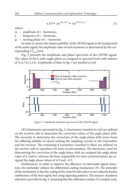
Fig. 3 presents the amplitude <strong>and</strong> phase spectrum of the OFDM signal.<br />
The values of the 0 rad/s angle phase are assigned to spectral levels with indexes<br />
of (1,4,7,8,11,14). Amplitudes of lines in fig. 3 are marked in red.<br />
Figure 3. Amplitude <strong>and</strong> phase spectrum of the OFDM signal<br />
Of 14 harmonics presented in fig. 3, 6 harmonics (marked in red) are utilized<br />
on the receiver side to determine the correction values of the angle phase drift.<br />
The necessity to determine the correction of the angle phase drift arises from<br />
the differing stability of clocks tacking the sampling circuits in the transmitter<br />
<strong>and</strong> the receiver. The remaining 8 harmonics (marked in blue) are utilized on<br />
the receiver side to reproduce the time synchronization. The harmonics used for<br />
determining the correction of the angle phase drift are assigned the angle phase<br />
value of 0 [rad/s], whereas the lines responsible for time synchronization are assigned<br />
the angle phase values of π/2 <strong>and</strong> –π/2.<br />
Furthermore, in order to improve the efficiency of watermark signal extraction,<br />
the embedder utilizes the differential coding mechanism [9]. The principle<br />
of the mechanism is that the coding of the same bit takes place in two adjacent frames<br />
(subframes) of the host signal, but using opposing patterns. The manner of pattern<br />
selection is provided in fig. 4. Assuming that the subframes contain 512 samples each,


